Embed Size (px)
Citation preview
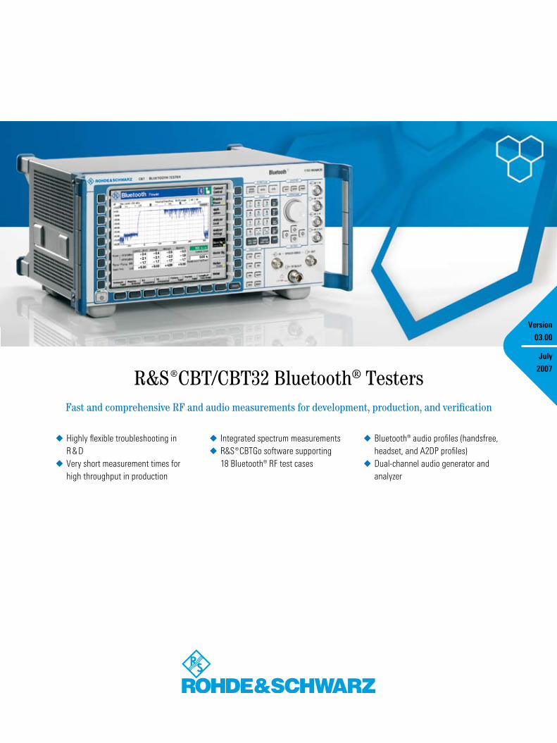
¸CBT/CBT32 Bluetooth® TestersFast and comprehensive RF and audio measurements for development, production, and verification
Version
03.00
July
2007
Highly flexible troubleshooting in R & DVery short measurement times for high throughput in production
◆
◆
Integrated spectrum measurements¸CBTGo software supporting 18 Bluetooth® RF test cases
◆
◆
Bluetooth® audio profiles (handsfree, headset, and A2DP profiles)Dual-channel audio generator and analyzer
◆
◆

2 ¸CBT/CBT32 Bluetooth® Testers
At a glance
The ¸CBT Bluetooth® testers perform Bluetooth® RF tests on all channels in hopping or non-hopping mode. They offer a large number of statistical monitoring and measure-ment functions. It is possible, for instance, to define tolerances for each measured value, or to stop a measure-ment sequence after a certain number of measurements or when a tolerance has been exceeded. In addition to the common traces for power, modulation, and spectrum, averaged minimum or maximum traces can be displayed over a user-defined number of packets.
The V2.0+EDR and V2.1+EDR Bluetooth® standards distinguish between basic rate and enhanced data rate (EDR) packets. Basic rate packets are already known from the V1.1 and V1.2 stan-dards. EDR packets use the same packet header as basic rate packets (GFSK mod-ulation) but transmit the payload using DPSK modulation (π/4-DQPSK or 8DPSK). The Bluetooth® transmitter must there-fore be able to switch over from GFSK to DPSK modulation within 5 µs. The DPSK modulation of the EDR packets yields a data transmission rate up to three times as high as that of basic rate packets. The Bluetooth® technology thus opens up new applications, e.g. the uncompressed transmission of CD audio signals. For all applications that do not require higher data rates, EDR packets lead to smaller
packet lengths. This reduces power con-sumption, which is particularly impor-tant for battery-powered devices (e.g. Bluetooth® headsets). The Bluetooth® RF test specification (V1.2/V2.0/V2.0+EDR/V2.1/V2.1+EDR) includes several test cases for EDR DUTs.
The ¸CBT-K55 EDR option adds a large number of EDR RF tests to the ¸CBT Bluetooth® testers.
¸CBT – the most versatile Bluetooth® tester for trouble-shooting in the lab
Using the ¸CBT, you can carry out a variety of spectrum measurements on an active Bluetooth® connection
¸CBT/CBT32 Bluetooth® Testers �
without requiring any extra spectrum analyzers. The ¸CBT‘s high versatil-ity results from the use of a paramet-ric measurement concept, which al-lows all Bluetooth® signal parameters to be set in virtually any desired combination. The effect of different pa-rameter combinations on results can be seen immediately. For example, most measurements can be performed on single frequencies or in hopping mode using any desired bit patterns and packet types.
Traces are output virtually in realtime on the ¸CBT‘s large graphical display. They can be analyzed in detail with the aid of switchable markers. Measurement parameters, e.g. level and frequency,
and other settings, e.g. marker positions, can conveniently be varied using the rotary knob. Power control is available in all TX measurement menus. It is thus easy to measure modulation or spectral characteristics at different transmit powers.
¸CBT – the record holder in speed for Bluetooth® tests in production
The ¸CBT uses parallel signal processing, and therefore performs Bluetooth® tests in production lines at extremely high speed. While conven-tional Bluetooth® testers sequentially measure power, modulation, frequency
accuracy, and finally frequency drift, the ¸CBT performs all these measure-ments in a single test cycle, thus offer-ing unparalleled speed for Bluetooth® TX measurements. The highly flexible remote-control programming makes it easy to adapt measurement con-figurations to any specific test require-ments, and measurements are then performed at maximum possible speed. For example, if measurements are to be carried out on five channels instead of the three channels used by conven-tional testers, the ¸CBT remote- control program can easily be modified to include two more channels. In the case of other testers, this would require running the entire test sequence a second time, which would considerably slow down the measurement process.
¸CBT and ¸CBT32 – the perfect combination for R & D and production
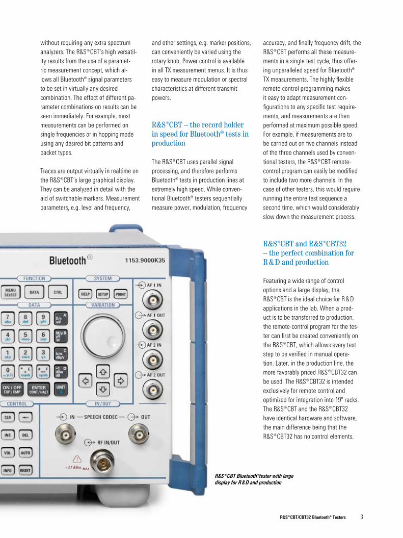
Featuring a wide range of control options and a large display, the ¸CBT is the ideal choice for R & D applications in the lab. When a prod-uct is to be transferred to production, the remote-control program for the tes-ter can first be created conveniently on the ¸CBT, which allows every test step to be verified in manual opera-tion. Later, in the production line, the more favorably priced ¸CBT�2 can be used. The ¸CBT�2 is intended exclusively for remote control and optimized for integration into 19" racks. The ¸CBT and the ¸CBT�2 have identical hardware and software, the main difference being that the ¸CBT�2 has no control elements.
¸CBT Bluetooth®tester with large display for R & D and production
Localactivation/enabling
Test controlcommands
DUT
Test data
¸CBT
Master
Slave
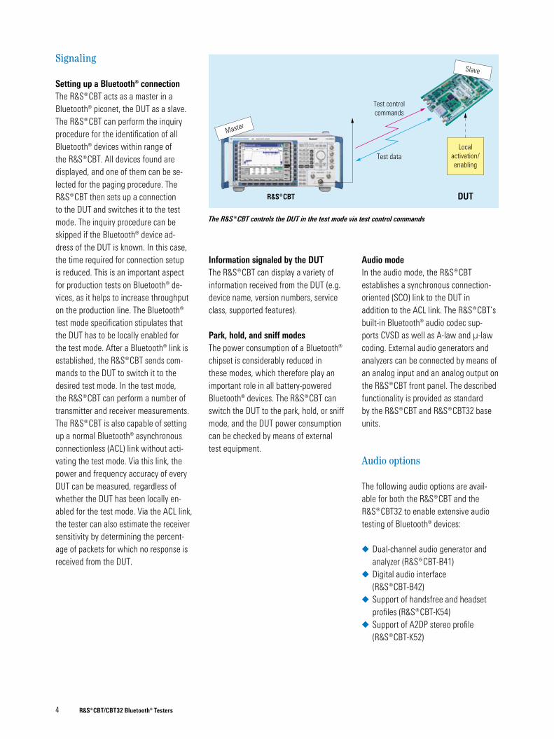
The ¸CBT controls the DUT in the test mode via test control commands
4 ¸CBT/CBT32 Bluetooth® Testers
Signaling
Setting up a Bluetooth® connectionThe ¸CBT acts as a master in a Bluetooth® piconet, the DUT as a slave. The ¸CBT can perform the inquiry procedure for the identification of all Bluetooth® devices within range of the ¸CBT. All devices found are displayed, and one of them can be se-lected for the paging procedure. The ¸CBT then sets up a connection to the DUT and switches it to the test mode. The inquiry procedure can be skipped if the Bluetooth® device ad-dress of the DUT is known. In this case, the time required for connection setup is reduced. This is an important aspect for production tests on Bluetooth® de-vices, as it helps to increase throughput on the production line. The Bluetooth® test mode specification stipulates that the DUT has to be locally enabled for the test mode. After a Bluetooth® link is established, the ¸CBT sends com-mands to the DUT to switch it to the desired test mode. In the test mode, the ¸CBT can perform a number of transmitter and receiver measurements. The ¸CBT is also capable of setting up a normal Bluetooth® asynchronous connectionless (ACL) link without acti-vating the test mode. Via this link, the power and frequency accuracy of every DUT can be measured, regardless of whether the DUT has been locally en-abled for the test mode. Via the ACL link, the tester can also estimate the receiver sensitivity by determining the percent-age of packets for which no response is received from the DUT.
Information signaled by the DUTThe ¸CBT can display a variety of information received from the DUT (e.g. device name, version numbers, service class, supported features).
Park, hold, and sniff modesThe power consumption of a Bluetooth® chipset is considerably reduced in these modes, which therefore play an important role in all battery-powered Bluetooth® devices. The ¸CBT can switch the DUT to the park, hold, or sniff mode, and the DUT power consumption can be checked by means of external test equipment.
Audio modeIn the audio mode, the ¸CBT establishes a synchronous connection-oriented (SCO) link to the DUT in addition to the ACL link. The ¸CBT’s built-in Bluetooth® audio codec sup-ports CVSD as well as A-law and µ-law coding. External audio generators and analyzers can be connected by means of an analog input and an analog output on the ¸CBT front panel. The described functionality is provided as standard by the ¸CBT and ¸CBT�2 base units.
Audio options
The following audio options are avail-able for both the ¸CBT and the ¸CBT�2 to enable extensive audio testing of Bluetooth® devices:
Dual-channel audio generator and analyzer (¸CBT-B41)Digital audio interface (¸CBT-B42)Support of handsfree and headset profiles (¸CBT-K54)Support of A2DP stereo profile (¸CBT-K52)
◆
◆
◆
◆

Measurement menu of the ¸CBT-B41 option in single-tone mode
Fast frequency response measurement of stereo signals with the ¸CBT-B41 option in multitone mode
¸CBT/CBT32 Bluetooth® Testers 5
¸CBT-B41 dual-channel audio generator and analyzer
The ¸CBT-B41 hardware option includes two audio generators and two audio analyzers for measuring the audio characteristics of Bluetooth® DUTs. The option adds four more connectors to the ¸CBT front panel: two output sockets for the audio generators and two input sockets for the audio analyzers. The audio signals are routed via internal audio switches either to the connectors for external equipment or to the internal Bluetooth® speech codec. Various test scenarios can be implemented:
Microphone test The DUT microphone, audio input amplifier, and A/D converter are tested. The ¸CBT generates an audio signal, which is applied to the DUT microphone via a reference loudspeaker. The DUT returns the audio signal to the ¸CBT via the Bluetooth® link, and the ¸CBT audio analyzer measures the signal.
Loudspeaker/ear piece test The DUT D/A converter, output ampli-fier, and loudspeaker/ear piece are tested. The ¸CBT generates an audio signal and sends it to the DUT via
the Bluetooth® link. The DUT outputs the audio signal via its sound converter. The signal is picked up by a reference microphone and taken via a reference amplifier to the ¸CBT, where audio analysis is performed.
Audio measurements
The ¸CBT-B41 option enables high-speed frequency response measure-ments in multitone mode. The user can define up to 20 tones in terms of level and frequency for each of the two audio channels.
In single-tone mode, the following measurements can be performed: audio level (RMS, peak), DC level, frequency, SINAD, THD+N (total harmonic distortion + noise). A THD measurement function is available in addition, which outputs the fundamental plus eight harmonics in the form of a bargraph.
Various filters are available for audio measurements:
19 fixed-frequency bandpass filtersOne variable bandpass filter (20 Hz to 20 kHz, bandwidth selectable from 10 Hz to 1000 Hz)Weighting filters (A, CCITT, C-message)
¸CBT-B42 digital audio interfaceThe ¸CBT-B42 hardware option expands the ¸CBT by a digital audio interface consisting of an input and an output in line with the S/P-DIF specifica-tion. The direct input of digital audio sig-nals avoids any distortion caused by D/A and A/D conversion in signal transmis-sion. For this option, the ¸CBT-B41 audio generator and analyzer option must be installed.
◆
◆
◆

Audio in
DUT
Audio tests (SCO)
Microphone test
¸CBT
AF1 inAF1 outAF2 inAF2 out
Speech codec out
Bluetooth® RF: SCO link
Speech codec inAF1 out
AF1 in
Audio generator 1
¸CBT-B41
Audio analyzer 1
Audio measurement of a DUT microphone with the ¸CBT-B41 option
AF amplifier
DUT
Audio out
Audio tests (ACL)
Audio testing of aBluetooth® stereo headset
¸CBT
AF1 inAF1 outAF2 inAF2 out
Bluetooth® RF: ACL link
(A2DP profile)
AF1 out
AF1 in AF2 in
¸CBT
AF2 out
Audio generator 1/2
¸CBT-B41
Audio analyzer 1/2
Audio measurement of a stereo headset using the A2DP profile
� ¸CBT/CBT32 Bluetooth® Testers
¸CBT-K54 handsfree and headset profilesTo perform audio measurements on any type of Bluetooth® handsfree or headset equipment, the ¸CBT must support the handsfree and headset pro-files. This capability is provided by the ¸CBT-K54 software option, which also allows links to be set up to the corresponding audio gateways (mobile phones, laptops).
¸CBT-K52 A2DP stereo profile and SBC codecThe ¸CBT-K52 software option has been designed for audio tests on Bluetooth® stereo DUTs (e.g. head-sets). The option supports the SBC stereo codec. This codec is mandatory for all Bluetooth® devices using the A2DP profile, and the ¸CBT is thus able to perform stereo audio tests on all DUTs employing this profile. For the ¸CBT-K52 option, the ¸CBT-B41 audio generator and analyzer option must be installed, as it provides a total of four audio connectors for the input and output of the analog stereo signals.

Power and guard time measurement of an EDR packet
¸CBT/CBT32 Bluetooth® Testers �
Power measurements (TX)
The current measurement values for each parameter are displayed on the ¸CBT screen. In addition, average, maximum, and minimum values are displayed as a result of a statistical evaluation of a settable number of Bluetooth® packets (bursts).
Output powerMeasurement parameters:
Nominal power: Average power from bit 0 to the last bit of the burstPeak power: Highest power level within the entire burst including the power rampsLeakage power: Average power across two measure-ment windows before and after the burst; the position and length of each window can be defined
Relative powerTo determine the power of EDR packets, the ¸CBT measures the average power within the GFSK portion as well as within the DPSK portion of an EDR packet and calculates the power difference.
Measurement parameters:
PGFSK (measured from bit 0 to the last bit of the packet header)PDPSK (measured from the first bit of the synchronization sequence to the last bit of the packet, excluding trailer bits)PDPSK – PGFSK (difference should be between –4 dB and +1 dB)
◆
◆
◆
◆
◆
◆
Power controlThe ¸CBT can send "Power up" and "Power down" commands to the DUT. Two keys are available for manual power control. After each keystroke, the ¸CBT displays the difference power level with respect to the previous level. The Bluetooth® specifications stipu-late that all difference values should be in the 2 dB to 8 dB range. When the maximum or minimum power level is reached, the DUT sends a message, which is displayed on the ¸CBT.
An outstanding feature of the ¸CBT is that power control functionality is available also for all frequency, modulation, and spectrum measurements.
Timing measurements (TX)
Measurement parameters:
Packet timing: Time difference between ideal master receiver slot and detected bit 0 of the received burst. This measurement is displayed on the Output Power screenGuard time (EDR): Time interval between the end of the last GFSK symbol of the packet header and the beginning of the ref-erence symbol of the synchronization sequence. This measurement is dis-played on the Relative Power screen
◆
◆

Modulation, frequency, and drift measurement of a basic rate packet
Frequency stability and modulation accuracy measurement of an EDR packet
8 ¸CBT/CBT32 Bluetooth® Testers
Modulation and frequency measurements (TX)
Measurement of basic rate packetsMeasurement parameters:
Frequency accuracy/initial carrier frequency tolerance (ICFT): Difference between the measured transmit frequency and the expected transmit frequency, measured in the preamble at the beginning of each packetCarrier frequency drift: Difference between the frequency at the start of a packet and the frequency in the payloadMaximum drift rate: Maximum drift rate, anywhere within the packet payloadFrequency deviation: Average, maximum, and minimum frequency deviation within the packet payload
In compliance with the Bluetooth® RF test specification, a minimum of 99.9 % of all measured bits must have a frequency deviation of at least 115 kHz. The ¸CBT shows the measured per-centage in a dedicated field (Bits Above Threshold) in the GFSK modulation menu. The 115 kHz threshold value can be varied as required.
EDR carrier stability and modulation accuracyTo perform these measurements, a Bluetooth® packet is first divided into the GFSK portion (packet header) and multiple blocks, each containing 50 symbols of the DPSK portion (payload).
◆
◆
◆
◆
Measurement parameters:
Carrier frequency stability (ωi): The ¸CBT determines the average frequency within the GFSK portion of a packet. The result ωi is the difference between the average frequency and the expected frequencyCarrier frequency stability (ω0 max): The ¸CBT determines the average frequency for each block of the DPSK portion relative to the average frequency within the GFSK portion, i.e. the result ω0 is the difference in each case. The largest measured ω0 value is displayed
◆
◆
RMS DEVM: The ¸CBT measures the differential error vector magnitude (DEVM) for each of the 50 symbols of a block. It then calculates the RMS DEVM value for each block and displays the largest valuePeak DEVM: The ¸CBT determines the peak DEVM value by analyzing all symbols of all blocks99 % DEVM: The ¸CBT displays the percentage of measured symbols whose DEVM value is at or below an adjustable threshold
◆
◆
◆

Constellation diagram of an EDR packet in differential symbol mode
Phase difference characteristic of an EDR packet
¸CBT/CBT32 Bluetooth® Testers 9
EDR differential phase encodingThis measurement checks whether the EDR encoder in the DUT is functioning properly. This is done by means of a BER measurement in the TX test mode. The DUT sends a predefined bit sequence to the ¸CBT, which compares the received bits with the expected bits.
Measurement parameters:BER (percentage of bit errors that have occurred within the current statistical cycle)Percentage of packets with 0 bit errors within the current statistical cycle
EDR I/Q constellation diagram and phase difference characteristicThe I/Q constellation diagram displays EDR packets in the I/Q plane. Bluetooth® EDR packets use differential modulation (DPSK); the I/Q diagram in the absolute symbol mode therefore does not provide any information as to the decodability of the signal. For this reason, the ¸CBT also offers a differential display in the I/Q plane (differential symbol mode), where the preceding symbol is used as a reference in each case. This enables assessment of the signal quality.
The phase difference characteristic shows the phase difference of each symbol relative to the preceding symbol as a function of time. The phase difference characteristic contains the bit information of each symbol and thus allows the individual symbols to be decoded. Using this characteristic, it is also possible to check the DPSK synchronization sequence.
◆
◆

EDR in-band spurious emissions measurement
20 dB bandwidth measurement
10 ¸CBT/CBT32 Bluetooth® Testers
Spectrum measurements (TX)
20 dB bandwidthThe graphic display in the 20 dB band-width measurement menu shows the frequency spectrum of the measured Bluetooth® channel. This spectrum measurement can be performed in hopping mode in addition to fixed frequencies.
Measurement parameters:
fL: Lowest frequency at which the power level drops to 20 dB below the peak power of the measurement channelfH: Highest frequency at which the power level drops to 20 dB below the peak power of the measurement channelfH – fL: Difference between the two values (should be smaller than 1 MHz)
The 20 dB reference value can be varied as required. The ¸CBT shows the results for the Current, Average, and Maximum display modes.
Frequency rangeThe graphic display in the frequency range measurement menu shows the spectral characteristic of the measured Bluetooth® signal at the upper and the lower end of the Bluetooth® frequency band.
Measurement parameters:
fL: Lowest frequency at which the power level drops to –�0 dBmfH: Highest frequency at which the power level drops to –�0 dBm
The –�0 dBm limit on the ¸CBT corresponds to a spectral power density of –80 dBm/Hz EIRP.
◆
◆
◆
◆
◆
Adjacent channel power (ACP)The ACP measurement menu shows the absolute power of a center channel as well as of three upper and three lower channels. All channels are user- selectable. The ¸CBT performs ACP measurements in compliance with the Bluetooth® RF test specification. The tester starts outputting results for all seven channels after less than a second, which considerably reduces test time in the lab as compared with the use of conventional spectrum analyzers.
EDR in-band spurious emissions (gated ACP)The ACP measurement menu includes a gating function that enables switch-over between normal and gated ACP measurements. The high flexibility of the ¸CBT allows you to perform normal as well as gated ACP measurements on both basic rate and EDR packets.
In the gating mode, the ¸CBT ad-ditionally displays the PTX ref and PTX – 2� dB results stipulated by the Bluetooth® RF test specification.

¸CBT/CBT32 Bluetooth® Testers 11
Special features
Channel display in frequency-hopping modeWith the ¸CBT, you can convenient-ly determine all RF channels in which the DUT exceeds specified tolerances. If On Limit Failure is set as a stop con-dition in frequency-hopping measure-ments, the ¸CBT automatically stops when a measured value exceeds a defin-able limit. The ¸CBT also displays the number of the channel in which the out-of-tolerance condition has occurred – a very helpful function for laboratory measurements.
Measurements without link setupMany Bluetooth® DUTs can be locally switched to the TX test mode via the HCI interface. The ¸CBT can then carry out power, frequency, and modulation measurements on the DUT without requiring a Bluetooth® link.
RX measurements
For RX measurements, the tester‘s built-in signal generator delivers a select-able bit sequence, which is sent to the DUT, looped back, and demodulated and processed by the ¸CBT. The TX level of the ¸CBT can be adjusted. When the EDR option is added, the receiver quality measurement menu offers EDR packet types (2-DH1, 2-DH�, and 2-DH5 as well as �-DH1, �-DH�, and �-DH5) in addition to the basic rate packet types (DH1, DH�, DH5).
BER/PER testsMeasurement parameters:
Bit error rate (BER): Percentage of errored bits returned by the DUTBit errors: Number of errored bits returned by the DUTNAK rate: Percentage of packets returned by the DUT with a negative acknowledgment (NAK). The DUT returns a packet with a NAK if it contains at least one bit errorPacket error rate (PER): Percentage of errored packets returned by the DUT. The ¸CBT ignores errored packets in the BER calculation
The PER result is broken down according to the following five criteria:
Missing packets: Percentage of packets not returned by the DUTHEC error: Percentage of returned packets containing non-correctable bit errors in the headerCRC error: Percentage of returned packets containing at least one error in the payload. These errors are bit errors that occur during retransmission of the packetWrong packet type: Percentage of returned packets with incorrect packet type. These are usu-ally null packetsWrong payload length: Percentage of packets returned with incorrect payload length
The ¸CBT offers a BER search function that automatically determines the DUT sensitivity level for a predefined BER level.
◆
◆
◆
◆
◆
◆
◆
◆
◆
Dirty transmitterFor BER tests, the Bluetooth® RF test specification stipulates a dirty transmitter (dirty TX) as a signal source in the tester.
Dirty transmitter for basic rate packetsEvery 20 ms, the dirty TX changes the frequency offset, modulation index, and symbol timing error. A table in the speci-fication lists ten different value combina-tions of these three parameters, which are used one after the other. The dirty TX additionally superimposes a defined fre-quency drift on its output signal; the fre-quency drift phase varies by 180° from packet to packet.
Dirty transmitter for EDR packetsEvery 20 packets, the dirty TX changes the frequency offset and symbol tim-ing error. A table in the specification lists three different value combina-tions of these two parameters, which are used one after the other. The dirty TX additionally superimposes a defined frequency drift on its output signal; the frequency drift phase varies by 180° from packet to packet.
The dirty TX in the ¸CBT and ¸CBT�2 can be operated in the following modes:
Dynamic dirty TX using the value table from the specification; drift superposition switched onDynamic dirty TX using a user-defined value table; drift superposition switched on or offStatic dirty TX; the values for frequency offset, modulation index, and symbol timing error can be set in any combination with one another; drift superposition switched on or off
◆
◆
◆
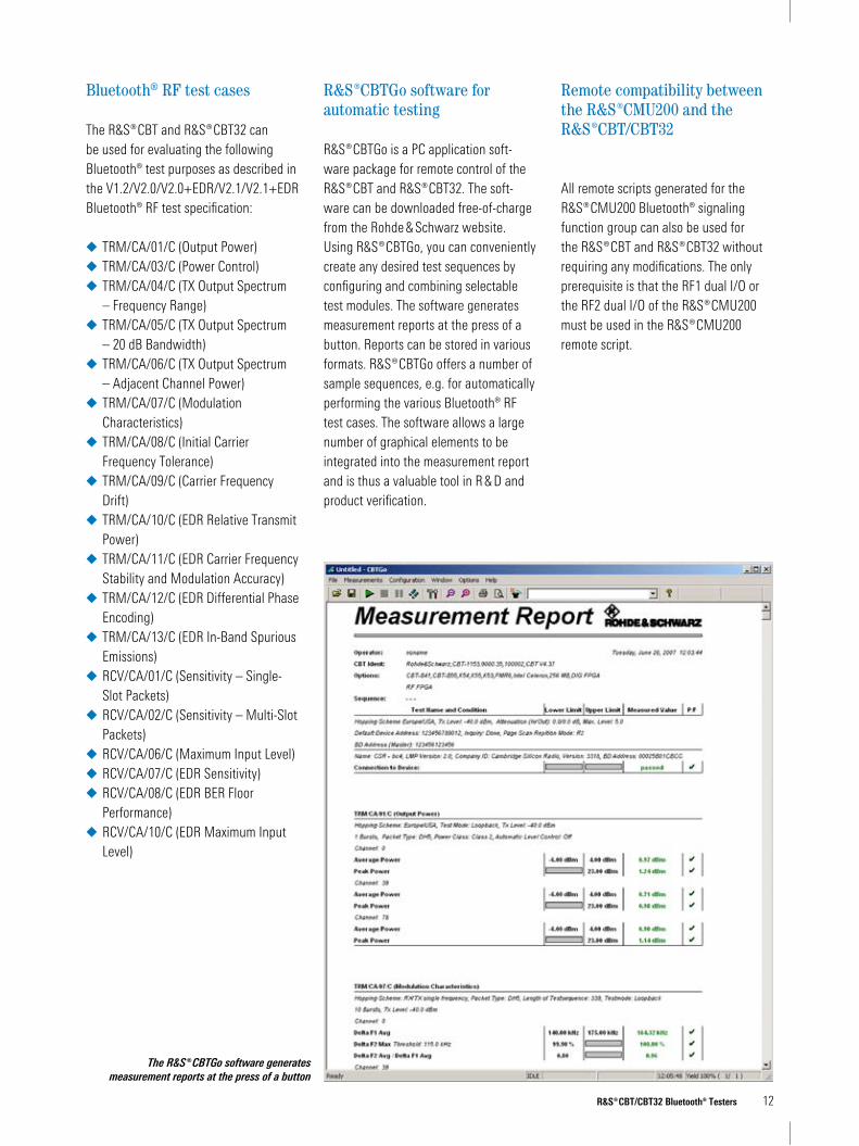
The ¸CBTGo software generates measurement reports at the press of a button
¸CBT/CBT32 Bluetooth® Testers 12
Bluetooth® RF test cases
The ¸CBT and ¸CBT�2 can be used for evaluating the following Bluetooth® test purposes as described in the V1.2/V2.0/V2.0+EDR/V2.1/V2.1+EDR Bluetooth® RF test specification:
TRM/CA/01/C (Output Power)TRM/CA/0�/C (Power Control)TRM/CA/04/C (TX Output Spectrum – Frequency Range)TRM/CA/05/C (TX Output Spectrum – 20 dB Bandwidth)TRM/CA/0�/C (TX Output Spectrum – Adjacent Channel Power)TRM/CA/0�/C (Modulation Characteristics)TRM/CA/08/C (Initial Carrier Frequency Tolerance)TRM/CA/09/C (Carrier Frequency Drift)TRM/CA/10/C (EDR Relative Transmit Power)TRM/CA/11/C (EDR Carrier Frequency Stability and Modulation Accuracy)TRM/CA/12/C (EDR Differential Phase Encoding)TRM/CA/1�/C (EDR In-Band Spurious Emissions)RCV/CA/01/C (Sensitivity – Single-Slot Packets)RCV/CA/02/C (Sensitivity – Multi-Slot Packets)RCV/CA/0�/C (Maximum Input Level)RCV/CA/0�/C (EDR Sensitivity)RCV/CA/08/C (EDR BER Floor Performance)RCV/CA/10/C (EDR Maximum Input Level)
◆
◆
◆
◆
◆
◆
◆
◆
◆
◆
◆
◆
◆
◆
◆
◆
◆
◆
¸CBTGo software for automatic testing
¸CBTGo is a PC application soft-ware package for remote control of the ¸CBT and ¸CBT�2. The soft-ware can be downloaded free-of-charge from the Rohde & Schwarz website. Using ¸CBTGo, you can conveniently create any desired test sequences by configuring and combining selectable test modules. The software generates measurement reports at the press of a button. Reports can be stored in various formats. ¸CBTGo offers a number of sample sequences, e.g. for automatically performing the various Bluetooth® RF test cases. The software allows a large number of graphical elements to be integrated into the measurement report and is thus a valuable tool in R & D and product verification.
Remote compatibility between the ¸CMU200 and the ¸CBT/CBT32
All remote scripts generated for the ¸CMU200 Bluetooth® signaling function group can also be used for the ¸CBT and ¸CBT�2 without requiring any modifications. The only prerequisite is that the RF1 dual I/O or the RF2 dual I/O of the ¸CMU200 must be used in the ¸CMU200 remote script.

The ¸CBT32 (bottom) is a cost-effective rack version of the ¸CBT (top) featuring identical test capabilities and optimized for use in production
¸CBT/CBT32 Bluetooth® Testers 1�
Ordering information
Designation Type Order No.
Bluetooth® Tester with display, 4 HU ¸CBT 115�.9000.�5
Bluetooth® Tester without display, 19", 2 HU, for remote control ¸CBT�2 115�.9000.�2
Hardware option for ¸CBT: Dual-Channel Audio Generator and Analyzer ¸CBT-B41 11�0.�40�.05
Hardware option for ¸CBT�2: Dual-Channel Audio Generator and Analyzer ¸CBT-B41 11�0.�40�.02
Hardware option for ¸CBT/CBT�2: Digital Audio Interface (S/P-DIF; ¸CBT-B41 required) ¸CBT-B42 11�0.��0�.0�
Software option for ¸CBT/CBT�2: A2DP Stereo Profile and SBC Codec (¸CBT-B41 required) ¸CBT-K52 11�0.4002.02
Software option for ¸CBT/CBT�2: Handsfree and Headset Profiles ¸CBT-K54 11�0.�80�.02
Software option for ¸CBT/CBT�2: Enhanced Data Rate (EDR) ¸CBT-K55 11�0.�20�.02
19" Adapter, 2 HU, for ¸CBT�2 ¸ZZA-211 109�.�2�0.00
19" Adapter, 4 HU, for ¸CBT ¸ZZA-S0� 1105.��5�.00
Documentation of Calibration Values ¸DCV-1 0240.218�.08
Antenna Coupler for Mobile Phones ¸CMU-Z10 1150.0801.10
RF Shielded Cover, extension for ¸CMU-Z10 ¸CMU-Z11 1150.1008.02
Bluetooth® Antenna, extension for ¸CMU-Z10 ¸CMU-Z12 1150.104�.02
The Bluetooth® word mark and logos are owned by the Bluetooth SIG, Inc. and any use of such marks by Rohde & Schwarz is under license.

Certified Quality System
ISO 9001DQS REG. NO 1954 QM
Certified Environmental System
ISO 14001DQS REG. NO 1954 UM
For data sheet, see PD 0�58.128�.22 and www.rohde-schwarz.com
(search term: CBT, CBT�2)
¸ is
a re
gist
ered
trad
emar
k of
Roh
de &
Sch
war
z Gm
bH &
Co.
KG
· Tra
de n
ames
are
trad
emar
ks o
f the
ow
ners
· Pr
inte
d in
Ger
man
y (c
h)PD
0�5
8.12
8�.1
2 · V
ersi
on 0
�.00
· Ju
ly 2
00�
· ¸CB
T/CB
T�2
· Dat
a w
ithou
t tol
eran
ce li
mits
is n
ot b
indi
ng ·
Subj
ect t
o ch
ange
www.rohde-schwarz.comEurope: +49 1805 12 4242, [email protected]
USA and Canada: +1-888-8��-8��2, [email protected]: +�5 �5 1�0 488, [email protected]

专注于微波、射频、天线设计人才的培养 易迪拓培训 网址:http://www.edatop.com
射 频 和 天 线 设 计 培 训 课 程 推 荐
易迪拓培训(www.edatop.com)由数名来自于研发第一线的资深工程师发起成立,致力并专注于微
波、射频、天线设计研发人才的培养;我们于 2006 年整合合并微波 EDA 网(www.mweda.com),现
已发展成为国内最大的微波射频和天线设计人才培养基地,成功推出多套微波射频以及天线设计经典
培训课程和 ADS、HFSS 等专业软件使用培训课程,广受客户好评;并先后与人民邮电出版社、电子
工业出版社合作出版了多本专业图书,帮助数万名工程师提升了专业技术能力。客户遍布中兴通讯、
研通高频、埃威航电、国人通信等多家国内知名公司,以及台湾工业技术研究院、永业科技、全一电
子等多家台湾地区企业。
易迪拓培训课程列表:http://www.edatop.com/peixun/rfe/129.html
射频工程师养成培训课程套装
该套装精选了射频专业基础培训课程、射频仿真设计培训课程和射频电
路测量培训课程三个类别共 30 门视频培训课程和 3 本图书教材;旨在
引领学员全面学习一个射频工程师需要熟悉、理解和掌握的专业知识和
研发设计能力。通过套装的学习,能够让学员完全达到和胜任一个合格
的射频工程师的要求…
课程网址:http://www.edatop.com/peixun/rfe/110.html
ADS 学习培训课程套装
该套装是迄今国内最全面、最权威的 ADS 培训教程,共包含 10 门 ADS
学习培训课程。课程是由具有多年 ADS 使用经验的微波射频与通信系
统设计领域资深专家讲解,并多结合设计实例,由浅入深、详细而又
全面地讲解了 ADS 在微波射频电路设计、通信系统设计和电磁仿真设
计方面的内容。能让您在最短的时间内学会使用 ADS,迅速提升个人技
术能力,把 ADS 真正应用到实际研发工作中去,成为 ADS 设计专家...
课程网址: http://www.edatop.com/peixun/ads/13.html
HFSS 学习培训课程套装
该套课程套装包含了本站全部 HFSS 培训课程,是迄今国内最全面、最
专业的HFSS培训教程套装,可以帮助您从零开始,全面深入学习HFSS
的各项功能和在多个方面的工程应用。购买套装,更可超值赠送 3 个月
免费学习答疑,随时解答您学习过程中遇到的棘手问题,让您的 HFSS
学习更加轻松顺畅…
课程网址:http://www.edatop.com/peixun/hfss/11.html
`

专注于微波、射频、天线设计人才的培养 易迪拓培训 网址:http://www.edatop.com
CST 学习培训课程套装
该培训套装由易迪拓培训联合微波 EDA 网共同推出,是最全面、系统、
专业的 CST 微波工作室培训课程套装,所有课程都由经验丰富的专家授
课,视频教学,可以帮助您从零开始,全面系统地学习 CST 微波工作的
各项功能及其在微波射频、天线设计等领域的设计应用。且购买该套装,
还可超值赠送 3 个月免费学习答疑…
课程网址:http://www.edatop.com/peixun/cst/24.html
HFSS 天线设计培训课程套装
套装包含 6 门视频课程和 1 本图书,课程从基础讲起,内容由浅入深,
理论介绍和实际操作讲解相结合,全面系统的讲解了 HFSS 天线设计的
全过程。是国内最全面、最专业的 HFSS 天线设计课程,可以帮助您快
速学习掌握如何使用 HFSS 设计天线,让天线设计不再难…
课程网址:http://www.edatop.com/peixun/hfss/122.html
13.56MHz NFC/RFID 线圈天线设计培训课程套装
套装包含 4 门视频培训课程,培训将 13.56MHz 线圈天线设计原理和仿
真设计实践相结合,全面系统地讲解了 13.56MHz线圈天线的工作原理、
设计方法、设计考量以及使用 HFSS 和 CST 仿真分析线圈天线的具体
操作,同时还介绍了 13.56MHz 线圈天线匹配电路的设计和调试。通过
该套课程的学习,可以帮助您快速学习掌握 13.56MHz 线圈天线及其匹
配电路的原理、设计和调试…
详情浏览:http://www.edatop.com/peixun/antenna/116.html
我们的课程优势:
※ 成立于 2004 年,10 多年丰富的行业经验,
※ 一直致力并专注于微波射频和天线设计工程师的培养,更了解该行业对人才的要求
※ 经验丰富的一线资深工程师讲授,结合实际工程案例,直观、实用、易学
联系我们:
※ 易迪拓培训官网:http://www.edatop.com
※ 微波 EDA 网:http://www.mweda.com
※ 官方淘宝店:http://shop36920890.taobao.com
专注于微波、射频、天线设计人才的培养
官方网址:http://www.edatop.com 易迪拓培训 淘宝网店:http://shop36920890.taobao.com