Embed Size (px)
Citation preview
73-0118-2505/09
Caution—ElECtriC toynot rECommEndEd for ChildrEn undEr fourtEEn yEars of agE. as with all ElECtriC produCts, prECautions should bE obsErvEd during handling and usE to prEvEnt ElECtriC shoCk. Transformer raTings—input: 120 vaC; 60 hz only. aC output: 18 v; 80 va
a Christmas storyready-to-run Train set
owner’s manual
a Christmas storyready-to-run Train set
owner’s manual

a Christmas story Train set inventory
• 0-8-0Locomotive• Tender• Boxcar• Gondolawithboxload• Reefercar• Portholewindowcaboose• CW-80Transformer• ThreestraightFasTracktracksections• EightcurvedFasTracktracksections• OnestraightFasTrackterminaltracksection• Smokefluid• Replacementtractiontire• Owner’sManual
Congratulations!
2
Congratulations on your purchase of the Lionel A Christmas Story Ready-To-Run Train Set! This set features everything you need to get started—a CW-80 Transformer, a huge loop of easy-to-
assemble FasTrack track, a string of detailed cars, and a powerful Lionel locomotive. Have fun growing with this complete train set! Start with the set components, then follow your
imagination into your own miniature world. Expand your railroad empire with additional FasTrack track sections, enhance your layout with accessories, lengthen your consist with extra cars, or operate a new locomotive at the head end of your train! Explore the possibilities at your authorized Lionel dealer.
Use this Owner’s Manual to learn how to set up, operate, and maintain your train set for years of reliable operation.
a Christmas story Train set features
• Brightheadlight• Puffingsmoke• Electronicwhistle• Forward-Neutral-Reverseoperation• Openingboxcardoors• Operatingcouplers
3
Thetransformerincludedwiththissetshouldbeperiodicallyexaminedforconditionsthatmayresultintheriskoffire,electricshock,orinjurytopersons(suchasdamagetotheoutputcord,blades,housing,orotherparts).Intheeventthatsuchconditionsexist,thetransformershouldnotbeuseduntilproperlyrepaired.
Parents!
A CHRISTMAS STORY and all related characters and elementsare trademarks of and © Turner Entertainment Co.WB SHIELD: TM & © Warner Bros. Entertainment Inc.(s09)
fCC statement
Warning: Changes or modifications to this unit not expressly approved by the party responsible for compliance could void the user's authority to operate the equipment.
Notes: This equipment has been tested and found to comply with the limits for a Class B digital device, pursuant to Part 15 of the FCC Rules. These limits are designed to provide reasonable protec-tion against harmful interference in a residential installation. This equipment generates, uses, and can radiate radio frequency energy and, if not installed and used in accordance with the instructions, may cause harmful interference to radio communications.
However, there is no guarantee that interference will not occur in a particular installation. If this equipment does cause harmful interference to radio or television reception, which can be determined by turning the equipement off and on, the user is encouraged to try to correct the interference by one or more of the following measures:
• Reorient or relocate the receiving antenna.
• Increase the separation between the equipment and receiver.
• Connect the equipment into an outlet on a circuit different from that to which the receiver is connected.
• Consult the dealer or an experienced radio/TV technician for help.
The following Lionel marks may be used throughout this instruction manual and are protected under law. All rights reserved.
Lionel®, TrainMaster®, Odyssey®, RailSounds®, CrewTalk™, TowerCom™, DynaChuff™, StationSounds™, Pullmor®, ElectroCoupler™, Magne-Traction®, CAB-1® Remote Controller, PowerMaster®, Lionel ZW®, ZW®, PowerHouse®, TMCC®, Lionelville™, Lockon®, Wireless Tether™, LionMaster®, FatBoy™, American Flyer®, TrainSounds™, PowerMax™, LEGACY™, PowerMax™ Plus, Odyssey II™, LEGACY RailSounds™
The name FasTrack® is used with permission from Pitsco, Inc.

4
Table of contents
Creating your layoutOperating your CW-80 Transformer safely 5Building your Lionel layout 6Joining the FasTrack track sections 7Wiring your CW-80 Transformer 7-8
Running your trainRunning your train set 9Adding smoke fluid to your locomotive’s smoke generator 10Coupling 11Operating your train with the CW-80 Transformer 11Experiencing the features of the CW-80 Transformer 12-13Reverse unit procedure 14
CW-80 Transformer operationPowering your layout with the CW-80 Transformer 15
Maintaining and servicing your setLubricating your locomotive 16Replacing your locomotive’s traction tire 17Replacing your locomotive’s headlamp 17Replacing your porthole caboose lamp 18Troubleshooting 19Lionel Limited Warranty Policy & Service 20
operating your CW-80 Transformer safely
5
Your Lionel CW-80 Transformer is listed by Underwriter’s Laboratory Inc. and has been carefully designed to ensure peak performance. When using electrical products, basic safety precautions
should be maintained.
Be sure to observe the following guidelines:
• Read the manual thoroughly before using this device.
• This device is not recommended for children under fourteen years of age.
• Parents should periodically inspect this product for potential hazards and, if necessary, have them repaired by an authorized Lionel Service Center. In the event that such a condition exists, the transformer should not be used until it has been properly repaired.
• The CW-80 Transformer is intended to be used indoors. Do not use this device if water is present. Serious or fatal injuries may result.
• Use the CW-80 Transformer only for its intended purpose.
• The CW-80 Transformer was meant to operate on 120-volt, 60-Hertz power. Do not connect this product to any other power supply.
• Do not operate the CW-80 Transformer with a damaged cord, plug, or case.
• To avoid the risk of electrical shock, do not disassemble the unit. There are no user serviceable parts inside. If damaged, take this product to an authorized Lionel Service Center. A list of autho-rized Service Centers is packed with this unit.
• Do not operate the CW-80 Transformer on your layout unattended. Obstructed accessories or stalled trains may overheat, resulting in damage to your layout.
• Always unplug the CW-80 Transformer from the power source when not in use.
• Never insert objects into the ventilation slots on this product. Damage to sensitive electronic components can result.
Creating your layout
6
Building your Lionel layout
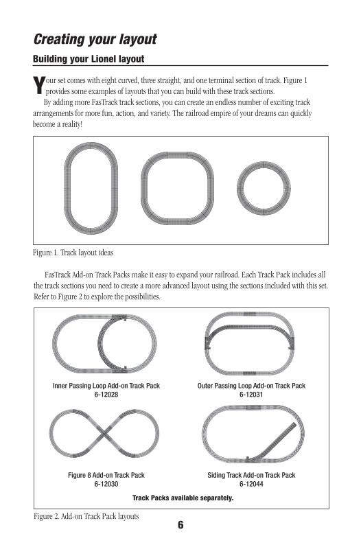
Your set comes with eight curved, three straight, and one terminal section of track. Figure 1 provides some examples of layouts that you can build with these track sections.
By adding more FasTrack track sections, you can create an endless number of exciting track arrangements for more fun, action, and variety. The railroad empire of your dreams can quickly become a reality!
Creating your layout
Figure 1. Track layout ideas
FasTrack Add-on Track Packs make it easy to expand your railroad. Each Track Pack includes all the track sections you need to create a more advanced layout using the sections included with this set. Refer to Figure 2 to explore the possibilities.
Figure 2. Add-on Track Pack layouts
inner passing loop add-on track pack6-12028
figure 8 add-on track pack6-12030
outer passing loop add-on track pack6-12031
siding track add-on track pack6-12044
Track Packs available separately.
Joining the fasTrack track sections
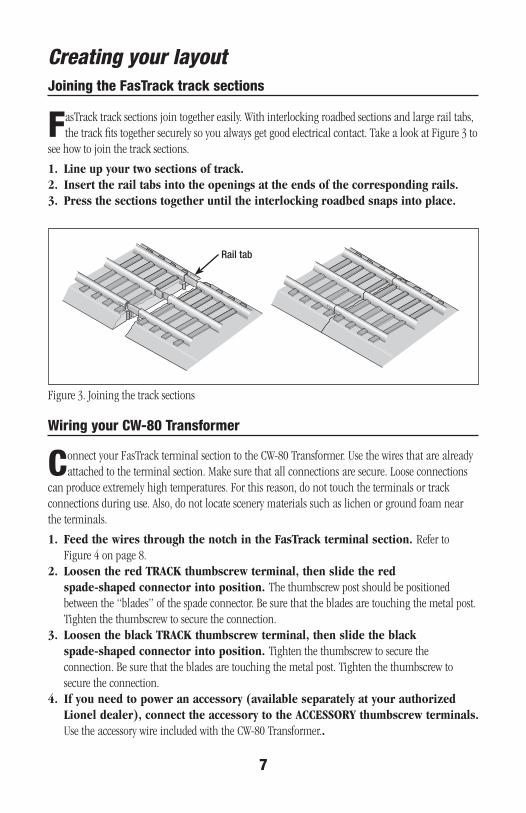
fasTrack track sections join together easily. With interlocking roadbed sections and large rail tabs, the track fits together securely so you always get good electrical contact. Take a look at Figure 3 to
see how to join the track sections.
1.Lineupyourtwosectionsoftrack.2.Inserttherailtabsintotheopeningsattheendsofthecorrespondingrails.3.Pressthesectionstogetheruntiltheinterlockingroadbedsnapsintoplace.
Figure 3. Joining the track sections
Creating your layout
7
rail tab
Wiring your CW-80 Transformer
Connect your FasTrack terminal section to the CW-80 Transformer. Use the wires that are already attached to the terminal section. Make sure that all connections are secure. Loose connections
can produce extremely high temperatures. For this reason, do not touch the terminals or track connections during use. Also, do not locate scenery materials such as lichen or ground foam near the terminals.
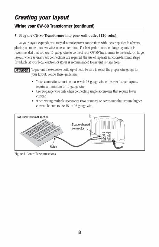
1.FeedthewiresthroughthenotchintheFasTrackterminalsection.Refer to Figure 4 on page 8.
2.LoosentheredTRACKthumbscrewterminal,thenslidetheredspade-shapedconnectorintoposition.The thumbscrew post should be positioned between the “blades” of the spade connector. Be sure that the blades are touching the metal post. Tighten the thumbscrew to secure the connection.
3.LoosentheblackTRACKthumbscrewterminal,thenslidetheblackspade-shapedconnectorintoposition.Tighten the thumbscrew to secure the connection. Be sure that the blades are touching the metal post. Tighten the thumbscrew to secure the connection.
4.Ifyouneedtopoweranaccessory(availableseparatelyatyourauthorizedLioneldealer),connecttheaccessorytotheACCESSORYthumbscrewterminals.Use the accessory wire included with the CW-80 Transformer..
Wiring your CW-80 Transformer (continued)
8
Creating your layout
5.PlugtheCW-80Transformerintoyourwalloutlet(120volts).
As your layout expands, you may also make power connections with the stripped ends of wires, placing no more than two wires on each terminal. For best performance on large layouts, it is recommended that you use 16-gauge wire to connect your CW-80 Transformer to the track. On larger layouts where several track connections are required, the use of separate junctions/terminal strips (available at your local electronics store) is recommended to prevent voltage drops.
To prevent the excessive build up of heat, be sure to select the proper wire gauge for your layout. Follow these guidelines:
• Track connections must be made with 18-gauge wire or heavier. Larger layouts require a minimum of 16-gauge wire.
• Use 24-gauge wire only when connecting single accessories that require lower current.
• When wiring multiple accessories (two or more) or accessories that require higher current, be sure to use 18- to 16-gauge wire.
Caution!
U120/60z
0~18VAC
A B
U
0~18VAC
TRACK ACCESSORY
Figure 4. Controller connections
fastrack terminal section
notch
spade-shaped connector
9
Running your trainrunning your train set
With track power off, place your train set on the track. Refer to page 11 for information on coupling the cars.
33
2
4
Power up your locomotive with your transformer.Yourlocomotiveisdesignedtooperateon7-15voltsalternatingcurrent. Virtually all Lionel and Lionel-compatible alternating-current transformers are suitable.
Do not power your locomotive with direct-current (DC) transformers. The locomotive was designed for use with alternating-current (AC) transformers only.
Move ‘em out!
Getyourlocomotivemoving. Your locomotive goes through a repeating pattern of operations: forward, neutral, reverse, neutral, and so on. To sequence the reverse unit, press the DIRECTION button on your transformer, or briefly bring the throttle all the way back to the OFF position and then forward. Each press of the DIRECTION button or interruption in track power causes the locomotive to advance to the next operational state.
Adjusttrackvoltage until your locomotive moves at your desired speed.
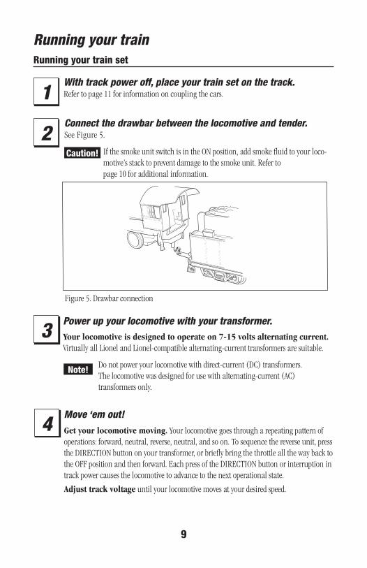
1Connect the drawbar between the locomotive and tender. See Figure 5.
If the smoke unit switch is in the ON position, add smoke fluid to your loco-motive’s stack to prevent damage to the smoke unit. Refer to page 10 for additional information.
Caution!
note!
Figure 5. Drawbar connection

Running your train
10
adding smoke fluid to your locomotive’s smoke generator
Y our locomotive is equipped with a smoke generator that produces safe, clean white smoke during operation if the smoke unit switch is in the ON position. Refer to Figure 8 on
page 14 for the location of the switch.The smoke generator requires the periodic addition of Lionel smoke fluid in order to function.
A small bottle of smoke fluid is included with this set. Press down and unscrew the cap. Pierce the tip on the nozzle. Add about four drops of fluid directly into the locomotive’s stack. Smoke pro-duction commences momentarily. It will start faster if you run your locomotive at higher speeds. When smoke production decreases, add more fluid (about four drops). An idle locomotive will not smoke.
Smoke production is greater at higher voltages and when the locomotive is pulling a heavy load or a long consist.
Caution! When the smoke unit switch is in the ON position, always keep a small amount of smoke fluid in the locomotive’s smoke generator; the generator’s element can become damaged if operated without smoke fluid. This is particularly true if your locomotive sits in neutral for an extended period of time without smoke fluid in the generator.
If you prefer to operate the locomotive without smoke or you do not want to add smoke fluid, slide the smoke unit switch to the OFF position.
note!

11
operating your trains with the CW-80 Transformer
You’re clear for departure! Move the throttle control handle forward to increase power to the track. The farther forward you push the handle, the faster your train will go.
Quickly shutting off or throwing the throttle all the way forward will not result in an instant change in track voltage.
When operating in the conventional (non-Command) environment, remember that the greater the load on the engine (adding more cars for the engine to pull, for example), the farther forward the handle must be pushed before it will operate the locomotive.
note!
Running your trainCoupling
When coupling your cars, at least one of the mating couplers must be open as shown at the left in Figure 6. Press down on the lock release to open the coupler, then push the cars toward
each other until they lock together.
Keep in mind that it’s easier to couple cars on a straight stretch of track.
lock release
Figure 6. Coupler operation
note!
12
Refer to Figure 7 on page 13 for the location of the Transformer features listed in this section.
THROTTLEPush the throttle forward to increase track power. The markings on the throttle approximate the
percentage of full power. For more realism, push the throttle slowly to gradually increase or decrease the speed of the locomotive. Slowing or stopping the locomotive with the throttle instead of the DIRECTION button will allow you to continue in the same direction when you increase the throttle again. To achieve this effect, reduce the throttle to the point that the locomotive stops moving, but don’t completely turn off the throttle. That way, your train won’t sequence into neutral.
DIRECTIONThe DIRECTION control button interrupts track power to activate the reverse unit in your
locomotive. Your locomotive will not respond to this button when the reverse unit switch is in the OFF position.
WHISTLEThe WHISTLE button will activate your locomotive’s whistle or horn. The sound will continue
until the button is released. No external sound activation buttons are needed.
Your locomotive features an electronic whistle in the tender.
BELLThe BELL button will activate the bell sounds on locomotives equipped with this feature. Press
and hold the BELL button for two to three seconds to begin the sounds; press and hold the button again to turn off the ringing.
Your locomotive is not equipped with bell sounds.
Do not activate horns, whistles, or bells on RailSounds-equipped locomotives until track power has been turned on for a few moments, or a continuous horn/whistle or bell sound may occur. To correct this problem, simply turn off the CW-80 Transformer, then turn it back on.
POWER-ON INDICATORThe green light will remain on during normal operation. The green light will begin to flash if
you exceed the power limit of the Transformer. The unit will allow you to momentarily exceed the power limit, but power will be gradually reduced until the problem is corrected. The benefit is that the Transformer will not instantly turn off.
Running your trainexperiencing the features of the CW-80 Transformer
note!
note!
note!
13
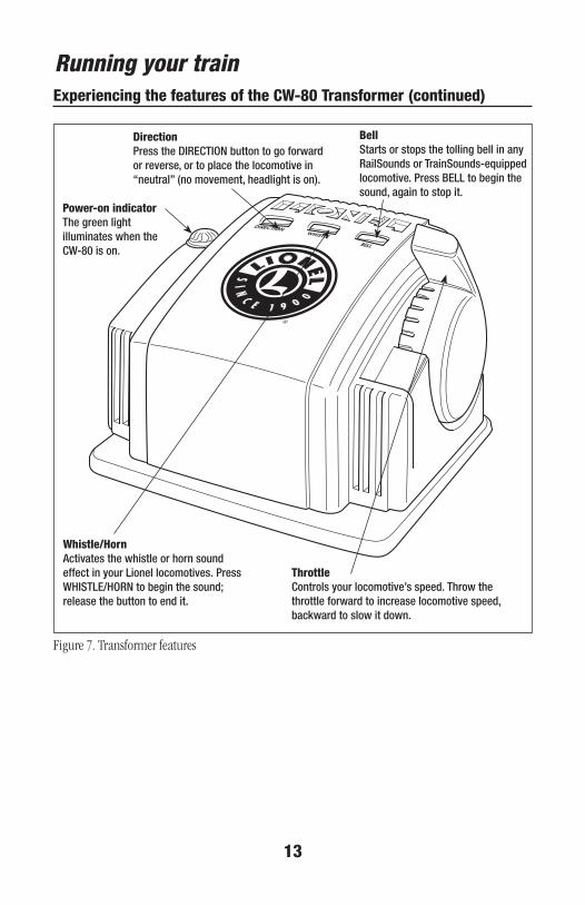
Whistle/Hornactivates the whistle or horn sound effect in your lionel locomotives. press whistlE/horn to begin the sound; release the button to end it.
Bellstarts or stops the tolling bell in any railsounds or trainsounds-equipped locomotive. press bEll to begin the sound, again to stop it.
Directionpress the dirECtion button to go forward or reverse, or to place the locomotive in “neutral” (no movement, headlight is on).
ThrottleControls your locomotive’s speed. throw the throttle forward to increase locomotive speed, backward to slow it down.
Power-on indicatorthe green light illuminates when the Cw-80 is on.
Figure 7. Transformer features
Running your trainexperiencing the features of the CW-80 Transformer (continued)
Running your trainreverse unit procedure
The electronic reverse unit inside your Lionel locomotive acts like the transmission in a car. When you apply power to the track, the locomotive moves in the direction specified by the reverse
unit—or it sits in neutral, awaiting another power interruption. Power interruptions are the signal that tells the reverse unit to sequence to the next operational state.
To interrupt power and sequence the locomotive’s reverse unit, press the direction control button or briefly bring the throttle lever all the way back to the OFF position. Refer to Figure 9 for the loca-tion of these controls. The reverse unit alternates between three states: forward, neutral, and reverse.
Also, the locomotive can be “locked” into a certain mode of operation by throwing the reverse unit switch located on the underside of the frame (see Figure 8). When the switch is thrown to the OFF (PROG) position (towards the rear of the locomotive), the locomotive will be locked in the next mode of operation in the sequence. To lock your locomotive into a specific operational state, sequence the locomotive into the desired state and reduce track power without completely powering down the locomotive, then throw the switch to the OFF position. The DIRECTION button will then have no affect on the direction of the locomotive. If you would like to resume forward-neutral-reverse operation, simply throw the reverse unit switch back to the ON (RUN) position.
Additionally, this reverse unit has a “power-up reset” feature. If the locomotive sits without power for a short period of time, the reverse unit will automatically reset and start in the forward direction when the transformer is turned on or “powered up,” regardless of the reverse unit switch position. If the switch is in the OFF position, the locomotive will start in the forward direction and be “locked” there.
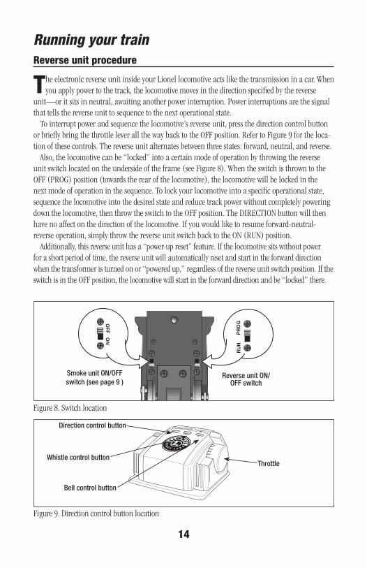
Figure 8. Switch location
Figure 9. Direction control button location
direction control button
whistle control button
bell control button
throttle
14
ON
OF
F
RU
NP
RO
G
reverse unit on/off switch
smoke unit on/off switch (see page 9 )
15
CW-80 Transformer operationPowering your layout with the CW-80 Transformer
Your CW-80 Transformer provides a total output of five amps. The track outputs will deliver all of this power to the track when no accessories are connected to the Transformer. Keep in mind that
connected accessories borrow some of this power. For example, if the accessories require two amps of the total five-amp capacity of the Transformer, you have three amps available for track power. This built-in flexibility will provide power for virtually any small- to medium-sized railroad. Also, available voltage depends on how much load is on the two outputs. Generally, track voltage and accessory volt-age are 0-18 volts (AC) each.
This Transformer is capable of operating trains up to and including dual-motored AC locomotives. To operate at this level of track power, it may be necessary to disconnect any accessories. You may also attempt to lower the accessory voltage settings.
You may momentarily approach or exceed the five-amp limit of the CW-80 Transformer when pulling illuminated cars, fighting over grades with heavy loads, or operating accessories. When you reach five amps, the green light on the Transformer will begin to flash. This indicates that the Transformer is in “fold-back mode.” In fold-back mode, the Transformer is automatically reducing, or folding back, power. This gradual reduction in power provides interruption-free operation while you bring the amperage back down to a safe level.
16
Maintaining and servicing your set
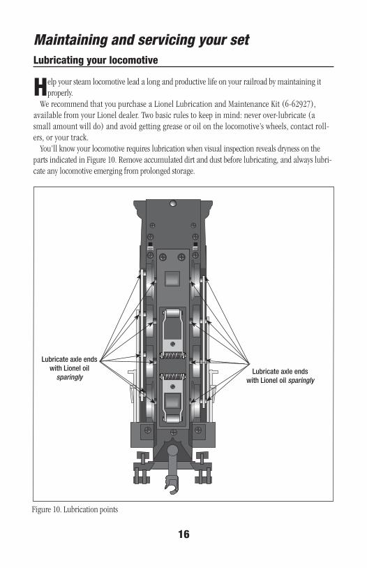
Figure 10. Lubrication points
Lubricating your locomotive
H elp your steam locomotive lead a long and productive life on your railroad by maintaining it properly.
We recommend that you purchase a Lionel Lubrication and Maintenance Kit (6-62927), available from your Lionel dealer. Two basic rules to keep in mind: never over-lubricate (a small amount will do) and avoid getting grease or oil on the locomotive’s wheels, contact roll-ers, or your track.
You’ll know your locomotive requires lubrication when visual inspection reveals dryness on the parts indicated in Figure 10. Remove accumulated dirt and dust before lubricating, and always lubri-cate any locomotive emerging from prolonged storage.
lubricate axle endswith lionel oil
sparinglylubricate axle ends
with lionel oil sparingly
Maintaining and servicing your set
17
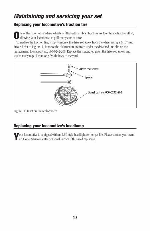
replacing your locomotive’s traction tire
one of the locomotive’s drive wheels is fitted with a rubber traction tire to enhance tractive effort, allowing your locomotive to pull many cars at once.
To replace the traction tire, simply unscrew the drive rod screw from the wheel using a 3/16” nut driver. Refer to Figure 11. Remove the old traction tire from under the drive rod and slip on the replacement, Lionel part no. 600-0242-206. Replace the spacer, retighten the drive rod screw, and you’r e ready to pull that long freight back to the yard.
replacing your locomotive’s headlamp
Your locomotive is equipped with an LED style headlight for longer life. Please contact your near-est Lionel Service Center or Lionel Service if this need replacing.
Figure 11. Traction tire replacement
lionel part no. 600-0242-206
spacer
drive rod screw
18
Maintaining and servicing your set
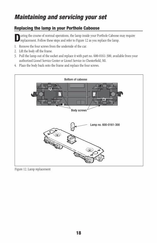
Figure 12. Lamp replacement
lamp no. 600-0161-300
replacing the lamp in your Porthole Caboose
During the course of normal operations, the lamp inside your Porthole Caboose may require replacement. Follow these steps and refer to Figure 12 as you replace the lamp.
1. Remove the four screws from the underside of the car. 2. Lift the body off the frame.3. Pull the lamp out of the socket and replace it with part no. 600-0161-300, available from your
authorized Lionel Service Center or Lionel Service in Chesterfield, MI.4. Place the body back onto the frame and replace the four screws.
body screws
bottom of caboose
19
Maintaining and servicing your setTroubleshooting
No lights or operationBe sure that the CW-80 Transformer is plugged in and the wires are connected.
Train runs, but WHISTLE, BELL, and DIRECTION buttons do not workCheck track connections. The track must be connected to the “A” and “U” terminals on the Transformer.
No change when DIRECTION button is pressedBe sure that your locomotive’s reverse unit switch is ON.
Accessory operation is intermittent or absentCheck for loose, shorted, or improper connections. Also, the accessory voltage may have been set too low for the accessory; refer to page 18 and reset the voltage to a higher level.
Locomotive runs slowly or lights dim at the far end of the trackOn larger layouts, additional track resistance may cause reduced track voltage as the trains move away from the power terminal section. Install additional FasTrack terminal sections around your layout and connect them to your Transformer to distribute power.
Green light begins to flashThe power limit of the Transformer has been exceeded. The unit will gradually reduce power until the problem is corrected.
Bell button blows whistleSwitch the wire connections at the Transformer terminals. The U terminal should be connected to the outside (common) rail.
Lionel Limited Warranty Policy & service
T his Lionel product, including all mechanical and electrical components, moving parts, motors and structural compo-nents, with the exception of LIGHT BULBS & LED’s are warranted to the original owner-purchaser for a period of one
yearfromtheoriginaldateofpurchase against original defects in materials or workmanship when purchased through a LionelAuthorizedRetailer*.
This warranty does NOT cover the following: Normal wear and tear, Light bulbs or LED’s, Defects appearing in the course of commercial use, or Damage resulting from abuse/misuse of the product.
Transfer of this product by the original owner-purchaser to another person voids this warranty in its entirety. Modification of this product in any way; visually mechanically or electronically, voids the warranty in its entirety.
Any warranted product which is defective in original materials or workmanship and is delivered by the original owner-purchaser (this warranty is non-transferrable) to Lionel LLC or any Lionel Authorized Service Station MUST be accompanied by the original receipt for purchase (or copy) from an LionelAuthorizedRetailer*, will at the discretion of Lionel LLC, be repaired or replaced, without charge for parts or labor. In the event the defective product cannot be repaired, and a suitable replacement is not available, Lionel will offer to replace the product with a comparable model (determinedbyLionelLLC), if available. In the event a comparable model is not available the customer will be refunded the original purchase price (requires proof of purchase from the LionelAuthorizedRetailer* it was originally purchased). Any products on which warranty service is sought must be sent freight or postage prepaid (Lionel will refuse any package when postage is due). Transportationandshippingchargesarenotcoveredaspartofthiswarranty.
NOTE:ProductsthatrequireservicethatdonothaveareceiptfromanLIONELAUTHORIZEDRETAILER*willberequiredtopay for all parts required to repair the product (labor will not incur a charge)providingtheproductisnotolderthan5yearsfromdateofmanufactureandiswithin1yearfromdateofpurchase.Acopyoftheoriginalsalesreceiptisrequired.
In no event shall Lionel LLC be held liable for incidental or consequential damages. Some states do not allow the exclusion or limitation of incidental or consequential damages, so the above exclusion may not
apply to you.This warranty gives you specific legal rights and you may have other rights which vary from state to state.
instructions for obtaining serviceIf service for this Lionel LLC product is required; bring the item, along with your DATED sales receipt and completed warranty
information (at the bottom of this page) to the nearest Lionel Authorized Service Station. Your nearest Lionel Service Station can be found by calling 1-800-4-LIONEL or by accessing the website at www.lionel.com.
If you prefer to send your Lionel product directly to Lionel, for repair you must FIRST call 586-949-4100 extension 9105 or FAX Lionel at 586-949-5429 or write to Customer Service, 50625 Richard W. Blvd, Chesterfield, MI 48051-2493. Please have the 6-digit Lionel product number, the date of original purchase, the dealer where the item was purchased and what seems to be the problem. You will receive a Verbal return authorization (RA) number to ensure your merchandise will be properly tracked and handled upon receipt at Lionel LLC.
Once you have your Return Authorization (RA) number, make sure the item is packed in its original Styrofoam inner con-tainer which is placed inside the original outer display box (this will help prevent damage during shipping and handling). This shipment MUST be prepaid and we recommend that it be insured with the carrier of your choice.
Please make sure you have followed all of the above instructions carefully before returning any merchandise for service. You may choose to have your product repaired by one of Lionel LLC’s Authorized Service Stations after its warranty has expired. A reasonable service fee should be expected once the product warranty has expired.
Warranty informationPlease complete the information below and keep it, along with your DATEDORIGINALSALESRECEIPT. You MUST
present this form AND your DATEDSALESRECEIPT when requesting warranty service.*A complete listing of Lionel Authorized retailers can be found by calling 1-800-4-LIONEL or by visiting our website at
www.lionel.com. Products that are more than 5 years old, from date of manufacture, are not applicable for warranty coverage, even
if they have never been sold prior to this date. (Under no circumstance shall any components or labor be provided free of charge.)
Name �����������������������������������������������������������������������������
Address ����������������������������������������������������������������������������
Place of Purchase ���������������������������������������������������������������������
Date of Purchase ����������������������������������������������������������������������
Product Number ����������������������������������������������������������������������
Product Description ��������������������������������������������������������������������
©2009 LIONEL L.L.C., CHESTERFIELD, MI 48051-2493UNITED STATES OF AMERICAPRINTED IN CHINA


![“What use could this company make of an electric toy? [the telephone]”](https://img.dokumen.tips/doc/110x75/56814710550346895db44995/what-use-could-this-company-make-of-an-electric-toy-the-telephone-5696e8b8464cc.jpg)

