Embed Size (px)
Citation preview
Caution: This document contains mixed page sizes (8.5 x 11 or 11 x 17), which may affect printing. Please adjust your printer settings
according to the size of each page you wish to print.

Service Manual
10.0 kW HDKAG Generator Sets
Printed in U.S.A. 981-051610-97

Page 1 of 1
�������������������
���������
����������
� ������� ���������������
�����������������������������
This Supplement transmits changes to Figure 4-5 to illustrate the location of the voltage adjustment pot onnewer voltage regulator boards. Replace Sheet 4-5/4-6 with the attached sheet.
4-5
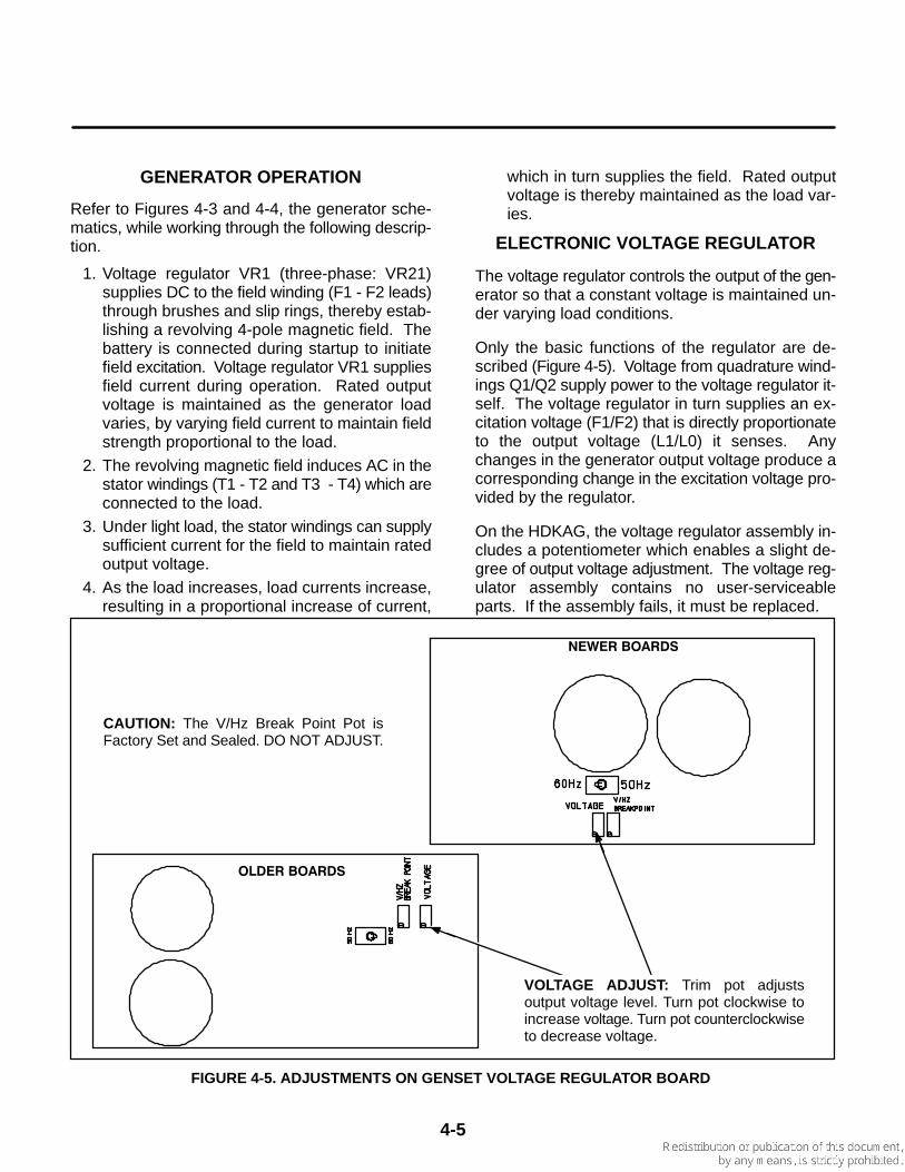
GENERATOR OPERATION
Refer to Figures 4-3 and 4-4, the generator sche-matics, while working through the following descrip-tion.
1. Voltage regulator VR1 (three-phase: VR21)supplies DC to the field winding (F1 - F2 leads)through brushes and slip rings, thereby estab-lishing a revolving 4-pole magnetic field. Thebattery is connected during startup to initiatefield excitation. Voltage regulator VR1 suppliesfield current during operation. Rated outputvoltage is maintained as the generator loadvaries, by varying field current to maintain fieldstrength proportional to the load.
2. The revolving magnetic field induces AC in thestator windings (T1 - T2 and T3 - T4) which areconnected to the load.
3. Under light load, the stator windings can supplysufficient current for the field to maintain ratedoutput voltage.
4. As the load increases, load currents increase,resulting in a proportional increase of current,
which in turn supplies the field. Rated outputvoltage is thereby maintained as the load var-ies.
ELECTRONIC VOLTAGE REGULATOR
The voltage regulator controls the output of the gen-erator so that a constant voltage is maintained un-der varying load conditions.
Only the basic functions of the regulator are de-scribed (Figure 4-5). Voltage from quadrature wind-ings Q1/Q2 supply power to the voltage regulator it-self. The voltage regulator in turn supplies an ex-citation voltage (F1/F2) that is directly proportionateto the output voltage (L1/L0) it senses. Anychanges in the generator output voltage produce acorresponding change in the excitation voltage pro-vided by the regulator.
On the HDKAG, the voltage regulator assembly in-cludes a potentiometer which enables a slight de-gree of output voltage adjustment. The voltage reg-ulator assembly contains no user-serviceableparts. If the assembly fails, it must be replaced.
FIGURE 4-5. ADJUSTMENTS ON GENSET VOLTAGE REGULATOR BOARD
�����������
����������
VOLTAGE ADJUST: Trim pot adjustsoutput voltage level. Turn pot clockwise toincrease voltage. Turn pot counterclockwiseto decrease voltage.
CAUTION: The V/Hz Break Point Pot isFactory Set and Sealed. DO NOT ADJUST.

4-6
GENERATOR SERVICE
Always disconnect the battery cables (negative [-]first) from the battery to prevent accidental startingof the set while servicing the generator.
������� Accidental starting of the set whileworking on it can cause severe injury. To pre-vent accidental starting, disconnect the batterycables (negative [-] first) from the battery.
The negative (-) cable is always disconnectedfirst, and connected last, to prevent arcing if atool accidentally touches the frame or othergrounded metal parts of the set while discon-necting or connecting the positive (+) cable.Arcing can ignite the explosive hydrogen gasgiven off by the battery, and cause severe inju-ry.
Brush Inspection/Replacement
The generator should be inspected for brush wearand cleaning every six months.
������� Accidental starting of the generatorset can cause severe personal injury or death.Stop the generator set and disable by discon-necting the starting battery cables (negative [-]cable first) before inspecting the generator.
1. Remove the access cover for the brush assem-bly.
2. Check the brushes for wear with a piece of wiremarked off 1 inch (25 mm) from one end (Fig-ure 4-6). Replace the brush and the spring ifthe wire goes into the brush holder 1 inch ormore.
3. To replace brushes, remove the brush holderby disconnecting the two leads to the holderand removing the two mounting screws.
4. Install the new brushes and springs in the hold-er and keep them in place during assembly byinserting a piece of wire through the holder, asshown in Figure 4-7.
5. Install the brush holder. After tightening themounting screws, pull out the brush retainingwire.
6. Connect the F1 lead to the inner brush terminal(nearest the rotor windings). Connect the F2lead to the outer brush terminal (nearest theend bell).
Slip Ring Inspection/Replacement
Inspect the slip rings for grooves, pits or other dam-age. If dust has accumulated on any generatorcomponents, they can be cleaned with filtered low-pressure air.
1. Examine the slip rings while servicing thebrushes.
2. If the rings need cleaning or service, removethe rotor from the generator and dress the ringson a lathe.
������� Dressing the slip rings on a latheimproperly may damage the generator rotor.Make certain that only an experienced techni-cian performs this job.
Generator Bearing
Inspect the bearing for evidence of outer case rota-tion every 1000 hours of use. The bearing shouldbe replaced every five years, because the bearinggrease gradually deteriorates due to oxidation.
Replace the O-ring if it shows evidence of wear ordeterioration. Renew grease if necessary (molyonly).

California
Proposition 65 WarningDiesel engine exhaust and some of its constituents are knownto the State of California to cause cancer, birth defects, andother reproductive harm.
i
Table of Contents
SAFETY PRECAUTIONS iii. . . . . . . . . . . . . . . . . . . . . . . . . . . . . . . . . . . . . . . . . . .
1 INTRODUCTION 1-1. . . . . . . . . . . . . . . . . . . . . . . . . . . . . . . . . . . . . . . . . . . . . . . . . . About This Manual 1-1. . . . . . . . . . . . . . . . . . . . . . . . . . . . . . . . . . . . . . . . . . . . . . . Assistance 1-1. . . . . . . . . . . . . . . . . . . . . . . . . . . . . . . . . . . . . . . . . . . . . . . . . . . . . . Test Equipment 1-1. . . . . . . . . . . . . . . . . . . . . . . . . . . . . . . . . . . . . . . . . . . . . . . . . . Safety Considerations 1-1. . . . . . . . . . . . . . . . . . . . . . . . . . . . . . . . . . . . . . . . . . . . Set Removal 1-3. . . . . . . . . . . . . . . . . . . . . . . . . . . . . . . . . . . . . . . . . . . . . . . . . . . .
2 ENGINE CONTROLS 2-1. . . . . . . . . . . . . . . . . . . . . . . . . . . . . . . . . . . . . . . . . . . . . . General 2-1. . . . . . . . . . . . . . . . . . . . . . . . . . . . . . . . . . . . . . . . . . . . . . . . . . . . . . . . Start Control at Set 2-1. . . . . . . . . . . . . . . . . . . . . . . . . . . . . . . . . . . . . . . . . . . . . . Control Troubleshooting 2-6. . . . . . . . . . . . . . . . . . . . . . . . . . . . . . . . . . . . . . . . . .
3 ENGINE CONTROL SERVICE 3-1. . . . . . . . . . . . . . . . . . . . . . . . . . . . . . . . . . . . . . General 3-1. . . . . . . . . . . . . . . . . . . . . . . . . . . . . . . . . . . . . . . . . . . . . . . . . . . . . . . . [A] Battery Check (BT1) 3-1. . . . . . . . . . . . . . . . . . . . . . . . . . . . . . . . . . . . . . . . . . [B] Battery Cable Check 3-1. . . . . . . . . . . . . . . . . . . . . . . . . . . . . . . . . . . . . . . . . . [C] Battery Charging Check 3-1. . . . . . . . . . . . . . . . . . . . . . . . . . . . . . . . . . . . . . . [D] Start Solenoid Check (K11) 3-1. . . . . . . . . . . . . . . . . . . . . . . . . . . . . . . . . . . . [E] Heater (Glow Plug) Relay Check (K13) 3-2. . . . . . . . . . . . . . . . . . . . . . . . . . [F] Fuel Solenoid Check (K14) 3-2. . . . . . . . . . . . . . . . . . . . . . . . . . . . . . . . . . . . [G] Start/Stop Switch Check (S11) 3-2. . . . . . . . . . . . . . . . . . . . . . . . . . . . . . . . . [H] Power Relay Check (A11-K12) 3-2. . . . . . . . . . . . . . . . . . . . . . . . . . . . . . . . .
4 GENERATOR/VOLTAGE REGULATOR 4-1. . . . . . . . . . . . . . . . . . . . . . . . . . . . . . General Description 4-1. . . . . . . . . . . . . . . . . . . . . . . . . . . . . . . . . . . . . . . . . . . . . . Generator Operation 4-5. . . . . . . . . . . . . . . . . . . . . . . . . . . . . . . . . . . . . . . . . . . . . Electronic Voltage Regulator 4-5. . . . . . . . . . . . . . . . . . . . . . . . . . . . . . . . . . . . . . Generator Service 4-6. . . . . . . . . . . . . . . . . . . . . . . . . . . . . . . . . . . . . . . . . . . . . . . Generator Disassembly/Assembly 4-8. . . . . . . . . . . . . . . . . . . . . . . . . . . . . . . . .
5 GENERATOR/REGULATOR TROUBLESHOOTING 5-1. . . . . . . . . . . . . . . . . . . General 5-1. . . . . . . . . . . . . . . . . . . . . . . . . . . . . . . . . . . . . . . . . . . . . . . . . . . . . . . . Troubleshooting Procedures 5-1. . . . . . . . . . . . . . . . . . . . . . . . . . . . . . . . . . . . . .
6 GENERATOR/REGULATOR TESTS 6-1. . . . . . . . . . . . . . . . . . . . . . . . . . . . . . . . . General 6-1. . . . . . . . . . . . . . . . . . . . . . . . . . . . . . . . . . . . . . . . . . . . . . . . . . . . . . . . [A] Testing Field Voltage 6-1. . . . . . . . . . . . . . . . . . . . . . . . . . . . . . . . . . . . . . . . . . [B] Testing Generator Rotor 6-1. . . . . . . . . . . . . . . . . . . . . . . . . . . . . . . . . . . . . . . [C] Testing Generator Stator 6-2. . . . . . . . . . . . . . . . . . . . . . . . . . . . . . . . . . . . . . [D] Dynamic Rotor/Stator Test 6-3. . . . . . . . . . . . . . . . . . . . . . . . . . . . . . . . . . . . . [E] Voltage Regulator Replacement 6-5. . . . . . . . . . . . . . . . . . . . . . . . . . . . . . . . [F] Wiring Harness Check 6-5. . . . . . . . . . . . . . . . . . . . . . . . . . . . . . . . . . . . . . . . [G] Voltage Adjustment 6-5. . . . . . . . . . . . . . . . . . . . . . . . . . . . . . . . . . . . . . . . . . . [H] Reconnection 6-5. . . . . . . . . . . . . . . . . . . . . . . . . . . . . . . . . . . . . . . . . . . . . . . .
ii
7 ROUTINE MAINTENANCE 7-1. . . . . . . . . . . . . . . . . . . . . . . . . . . . . . . . . . . . . . . . . Introduction 7-1. . . . . . . . . . . . . . . . . . . . . . . . . . . . . . . . . . . . . . . . . . . . . . . . . . . . . Maintenance Schedule 7-1. . . . . . . . . . . . . . . . . . . . . . . . . . . . . . . . . . . . . . . . . . . Generator Set Inspection 7-2. . . . . . . . . . . . . . . . . . . . . . . . . . . . . . . . . . . . . . . . . Oil and Filter Change 7-3. . . . . . . . . . . . . . . . . . . . . . . . . . . . . . . . . . . . . . . . . . . . Cooling System 7-4. . . . . . . . . . . . . . . . . . . . . . . . . . . . . . . . . . . . . . . . . . . . . . . . . Fan Belt 7-6. . . . . . . . . . . . . . . . . . . . . . . . . . . . . . . . . . . . . . . . . . . . . . . . . . . . . . . . Fuel System 7-7. . . . . . . . . . . . . . . . . . . . . . . . . . . . . . . . . . . . . . . . . . . . . . . . . . . . Air Cleaner 7-9. . . . . . . . . . . . . . . . . . . . . . . . . . . . . . . . . . . . . . . . . . . . . . . . . . . . . Battery Care 7-9. . . . . . . . . . . . . . . . . . . . . . . . . . . . . . . . . . . . . . . . . . . . . . . . . . . . AC Generator 7-10. . . . . . . . . . . . . . . . . . . . . . . . . . . . . . . . . . . . . . . . . . . . . . . . . . Crankcase Breather 7-10. . . . . . . . . . . . . . . . . . . . . . . . . . . . . . . . . . . . . . . . . . . . . Muffler/Spark Arrester 7-11. . . . . . . . . . . . . . . . . . . . . . . . . . . . . . . . . . . . . . . . . . . Cleaning the Generator Set 7-11. . . . . . . . . . . . . . . . . . . . . . . . . . . . . . . . . . . . . . Initial Starting and Checks 7-11. . . . . . . . . . . . . . . . . . . . . . . . . . . . . . . . . . . . . . .
8 WIRING DIAGRAMS 8-1. . . . . . . . . . . . . . . . . . . . . . . . . . . . . . . . . . . . . . . . . . . . . .
iii
Safety Precautions
Thoroughly read the OPERATOR’S MANUALbefore operating the genset. Safe operation andtop performance can be obtained only withproper operation and maintenance.
The following symbols in this Manual alert you topotential hazards to the operator, service personand equipment.
Alerts you to an immediate hazardwhich will result in severe personal injury ordeath.
Alerts you to a hazard or unsafepractice which can result in severe personal in-jury or death.
Alerts you to a hazard or unsafepractice which can result in personal injury orequipment damage.
Electricity, fuel, exhaust, moving parts and batteriespresent hazards which can result in severe person-al injury or death.
GENERAL PRECAUTIONS
• Keep ABC fire extinguishers handy.
• Make sure all fasteners are secure and torquedproperly.
• Keep the genset and its compartment clean.Excess oil and oily rags can catch fire. Dirt andgear stowed in the compartment can restrictcooling air.
• Let the engine cool down before removing thecoolant pressure cap or opening the coolantdrain. Hot coolant under pressure can sprayout and cause severe burns.
• Before working on the genset, disconnect thenegative (- ) battery cable at the battery to pre-vent starting.
• Use caution when making adjustments whilethe genset is running—hot, moving or electri-cally live parts can cause severe personal inju-ry or death.
• Used engine oil has been identified by somestate and federal agencies as causing canceror reproductive toxicity. Do not ingest, inhale,or contact used oil or its vapors.
• Benzene and lead in some gasolines havebeen identified by some state and federalagencies as causing cancer or reproductivetoxicity. Do not to ingest, inhale or contact gas-oline or its vapors.
• Do not work on the genset when mentally orphysically fatigued or after consuming alcoholor drugs.
• Carefully follow all applicable local, state andfederal codes.
GENERATOR VOLTAGE IS DEADLY!
• Generator output connections must be madeby a qualified electrician in accordance with ap-plicable codes.
• The genset must not be connected to the publicutility or any other source of electrical power.Connection could lead to electrocution of utilityworkers, damage to equipment and fire. An ap-proved switching device must be used to pre-vent interconnections.
• Use caution when working on live electricalequipment. Remove jewelry, make sure cloth-ing and shoes are dry and stand on a dry wood-en platform on the ground or floor.
FUEL IS FLAMMABLE AND EXPLOSIVE
• Keep flames, cigarettes, sparks, pilot lights,electrical arc-producing equipment andswitches and all other sources of ignition wellaway from areas where fuel fumes are presentand areas sharing ventilation.
• Fuel lines must be secured, free of leaks andseparated or shielded from electrical wiring.
• Use approved non-conductive flexible fuelhose for fuel connections at the genset.
iv
ENGINE EXHAUST IS DEADLY!
• Learn the symptoms of carbon monoxide poi-soning in this Manual.
• Never sleep in the vehicle while the genset isrunning unless the vehicle has a working car-bon monoxide detector.
• The exhaust system must be installed in accor-dance with the genset Installation Manual.
• Do not use engine cooling air to heat the ve-hicle interior.
• Make sure there is ample fresh air when oper-ating the genset in a confined area.
MOVING PARTS CAN CAUSE SEVEREPERSONAL INJURY OR DEATH
• Do not wear loose clothing or jewelry near mov-ing parts such as PTO shafts, fans, belts andpulleys.
• Keep hands away from moving parts.
• Keep guards in place over fans, belts, pulleys,etc.
BATTERY GAS IS EXPLOSIVE
• Wear safety glasses and do not smoke whileservicing batteries.
• When disconnecting or reconnecting batterycables, always disconnect the negative (- ) bat-tery cable first and reconnect it last to reducearcing.
DO NOT OPERATE IN FLAMMABLE ANDEXPLOSIVE ENVIRONMENTS
Flammable vapor can cause a diesel engine tooverspeed and become difficult to stop, resulting inpossible fire, explosion, severe personal injury anddeath. Do not operate a diesel-powered gensetwhere a flammable vapor environment can becreated by fuel spill, leak, etc., unless the gen-set is equipped with an automatic safety deviceto block the air intake and stop the engine. Theowners and operators of the genset are solely re-sponsible for operating the genset safely. Contactyour authorized Onan/Cummins dealer or distribu-tor for more information.
Mobile-3
1. Introduction
1-1
ABOUT THIS MANUAL
This manual contains troubleshooting and repairdata for these components of the HDKAG genera-tor set:
• Control• Generator
See the Engine Service Manual for engine informa-tion.
Study this manual carefully. Heed all warnings andcautions. Proper use and maintenance can result inlonger set life, better performance and safer opera-tion.
This manual contains basic wiring diagrams andschematics for troubleshooting. Techniciansshould use the wiring diagram and schematicshipped with each unit. Update these diagrams andschematics when the set is modified.
PC board information is limited; in the field, it ismore efficient to replace the boards than to attemptrepair.
ASSISTANCE
When contacting an Onan distributor, supply thecomplete model number and serial number shownon the Onan nameplate on the side of the generatorcontrol box.
TEST EQUIPMENT
• Multimeter/digital VOM• AC voltmeter• DC voltmeter• Frequency meter• Jumper leads• Load test panel• Megger or insulation resistance meter• Wheatstone bridge or digital ohmmeter
WARNING Incorrect service or replacement ofparts can result in severe personal injury,death, and /or equipment damage. Service per-sonnel must be qualified to perform electricaland mechanical service.
SAFETY CONSIDERATIONS
Generator sets present safety hazards that thetechnician must know about. Read the precautionson the inside cover of this manual. Familiarize your-self with the hazards shown in Table 1-1. When thehazards are known, approach the job with a safety-conscious attitude. Being safety-conscious is thebest way to avoid injury. Reduce the chance of anaccident with the following safeguards.
Safeguards To Avoid Hazards
• Use Protective Clothing. Protect your bodyby wearing protective clothing such as:
• Safety shoes• Gloves• Safety glasses• Hard hats
Leave rings and jewelry off. Do not wear looseclothing that might get caught on equipment.
• Reduce Workshop Hazards.
• Keep guards and shields in place onmachinery
• Maintain equipment in good working order• Store flammable liquids in approved
containers away from open flame, spark, pilot light, cigarette, or other ignition source
• Keep the workshop clean and well-lighted• Provide adequate ventilation• Keep a fire extinguisher and safety
equipment nearby• Be prepared to respond to an emergency
• Develop Safe Work Habits.
Unsafe actions are the source of most acci-dents with tools and machines. Be familiar withthe equipment and know how to use it safely.Use the right tool for the job, and check its con-dition before starting. Observe the warningsand cautions in this manual and take specialprecautions when working around electricalequipment. Do not work alone if possible anddo not take unnecessary risks.

1-2
• Be prepared if an accident occurs.
Agencies such as the Red Cross and local policeand fire departments offer courses in first aid, CPR,and fire control. Take advantage of this information
to be ready to respond to an accident. Learn to besafety conscious and make safe practices a part ofyour work routine. Do not work when tired or afterconsuming any alcohol or drug that makes the op-eration of equipment unsafe.
• Fire and explosions• Leaking fuel• Hydrogen gas from charging battery• Oily rags improperly stored• Flammable liquids improperly stored• Any fire, flame, spark, pilot light, arc-
producing equipment or other ignitionsources
• Burns • Hot exhaust pipes• Hot engine and generator surfaces• Hot engine oil• Electrical short in DC wiring system• Hot engine coolant
• Poisonous gases• Carbon monoxide from faulty exhaust
pipes, joints or hangers• Operating generator set where
exhaust gases can accumulate
• Electrical shock (AC)• Improper genset load connections• Faulty RV wiring• Faulty electrical appliance• Faulty genset wiring• Working in damp conditions• Jewelry touching electrical components
• Rotating Machinery • Flywheel fan guard not in place• Jewelry or loose clothing catching in
moving parts
• Slippery Surfaces• Leaking or spilled oil
• Heavy Objects• Removing generator set from RV• Removing heavy components
TABLE 1-1HAZARDS AND THEIR SOURCES
1-3
SET REMOVAL
Some service procedures require removing thegenerator set from the vehicle. Because of the widevariety of installations, it is not possible to specifyexact removal procedures for each genset. If a sat-isfactory method for removing a particular set can-not be determined, contact the vehicle manufactur-er or the set installer for their recommendations.
WARNING Generator sets are heavy and theycan cause severe personal injury or death ifdropped during removal. Use adequate liftingdevices to provide sufficient support for the set.Keep hands and feet clear while lifting the gen-erator set. Before starting set removal, placethe transmission in park, set the emergencybrake, and remove the negative (-) cable fromthe vehicle ignition system battery to avoid in-advertent movement of the vehicle.
Disconnecting Generator Set Systems
Some installations require partial removal of the setto gain access to the battery cable, fuel line, andother connections. Read this entire section beforestarting set removal. The following steps are a gen-eral guideline.
WARNING Leakage of fuel in or around thegenerator set compartment presents the hazardof fire or explosion that can cause severe per-sonal injury or death. Do not disconnect or con-nect battery cables if fuel vapors are present.Ventilate the compartment thoroughly: park ve-hicles outdoors in a well ventilated area.
1. Disconnect the generator set negative (-) bat-tery cable at the battery terminal.
2. Disconnect the generator set positive (+) bat-tery cable from the wire harness.
3. Disconnect the remote control plug wire fromthe generator set (if applicable).
4. Disconnect the generator load wires. Tag foridentification when reconnecting.
5. Disconnect the exhaust system and supportbrackets or hangers, to allow set removal.
6. Disconnect the fuel line at the genset housing.Securely plug the end of the fuel line to preventfuel leakage.
7. Verify that the set is adequately supported be-fore loosening any mounting bolts or supportmembers.
WARNING Leakage of fuel presents the hazardof fire or explosion that can cause severe per-sonal injury or death. Make certain all fuel lineopenings are plugged. Before disconnectingthe fuel line, be certain there are no ignitionsources such as flame, spark, pilot light, ciga-rette, etc., near the generator set. Keep an ABCtype fire extinguisher nearby.
When reinstalling the set, be sure all mountinghardware, and electrical, exhaust, and fuel systemcomponents are connected exactly as they werebefore removal. See the appropriate installationmanual during reinstallation for important safetyprecautions.
Check for oil and fuel leaks. Check the exhaust sys-tem audibly and visually with the generator set run-ning. Repair leaks immediately. Replace worn,damaged, or corroded exhaust and fuel line compo-nents before leaks occur.

1-4
Blank Page
2. Engine Controls
2-1
GENERAL
This section describes the generator set preheat/start/run control system. The set may be started ei-ther at the onboard DC control box or by using a re-motely mounted start control.
START CONTROL AT SET
The set is started with a Start/Stop/Preheat switchon the front panel of the DC control box. Componentreferences are found on wiring/schematic diagramsin the Wiring Diagrams section of this manual.
The DC control box does not contain meters and isdesigned for remote mounting within limits of thewire harness (approximately 32 inches [813 mm]).An optional remote control panel with meters isavailable in a kit from Onan.
Switches
Start-Stop/Preheat Switch S11: Starts and stopsthe unit locally. Preheat function occurs when theswitch is held in the Stop position. The unit may alsobe operated from a remote switch wired to recep-tacle J3 on the rear panel.
Circuit Breakers
DC Control Breaker CB11: A 15 ampere DCbreaker providing protection to the control box wir-ing and remote wiring from short circuits or over-load. Also serves as an emergency stop switch.
Fault Breaker CB12: A manual reset breaker thatshuts down the engine for low oil pressure and highcoolant temperatures.
Control Components
The following describes the basic engine controlcomponents and how they function.
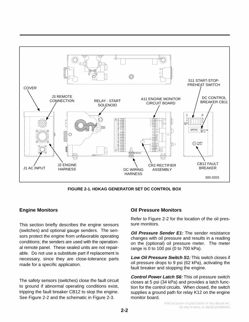
A11 Engine Monitor Circuit Board: A circuit boardthat monitors the engine control system functions.This includes starting, stopping, and fault systemoperation. Terminals are included for making re-mote connections. See Figure 2-1.
Two relays soldered into the engine monitor boardare not serviceable. They function as follows:
• Power relay K12 connects battery B+ to thecontrol meters and fuel solenoid during opera-tion.
• Starter protection relay K15 is AC operated.When the Start switch is pressed, B+ is con-nected to K11 start solenoid through the K15NC contacts until the generator output reachesabout 90 volts AC. At this voltage K15 acti-vates and disconnects the starter circuit.
K11 Start Solenoid: Located over the engine moni-tor circuit board (above K13 glow plug heater sole-noid). It connects battery B+ to the start solenoid,K13 heater solenoid, fuel solenoid and meters dur-ing cranking.
K13 Glow Plug Heater Solenoid: Located directlyabove the monitor circuit board. Connects B+ to theengine glow plugs during cranking. It is energizedby K11 start solenoid.
K14 Fuel Solenoid: It opens the fuel control valvewhen the start/stop switch is placed in the Startposition.
2-2
FIGURE 2-1. HDKAG GENERATOR SET DC CONTROL BOX
300-3203
A11 ENGINE MONITORCIRCUIT BOARD
RELAY - STARTSOLENOID
CB12 FAULTBREAKER
DC CONTROLBREAKER CB11
S11 START-STOP-PREHEAT SWITCH
COVER
DC WIRINGHARNESS
CR2 RECTIFIERASSEMBLY
J3 REMOTECONNECTION
J1 AC INPUTJ2 ENGINEHARNESS
Engine Monitors
This section briefly describes the engine sensors(switches) and optional gauge senders. The sen-sors protect the engine from unfavorable operatingconditions; the senders are used with the operation-al remote panel. These sealed units are not repair-able. Do not use a substitute part if replacement isnecessary, since they are close-tolerance partsmade for a specific application.
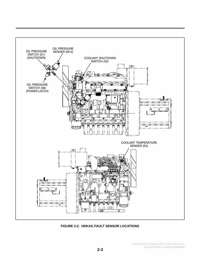
The safety sensors (switches) close the fault circuitto ground if abnormal operating conditions exist,tripping the fault breaker CB12 to stop the engine.See Figure 2-2 and the schematic in Figure 2-3.
Oil Pressure Monitors
Refer to Figure 2-2 for the location of the oil pres-sure monitors.
Oil Pressure Sender E1: The sender resistancechanges with oil pressure and results in a readingon the (optional) oil pressure meter. The meterrange is 0 to 100 psi (0 to 700 kPa).
Low Oil Pressure Switch S1: This switch closes ifoil pressure drops to 9 psi (62 kPa), activating thefault breaker and stopping the engine.
Control Power Latch S6: This oil pressure switchcloses at 5 psi (34 kPa) and provides a latch func-tion for the control circuits. When closed, the switchsupplies a ground path for relay K12 on the enginemonitor board.
2-3
FIGURE 2-2. HDKAG FAULT SENSOR LOCATIONS
OIL PRESSURESWITCH (S1)(SHUTDOWN)
OIL PRESSURESENDER (M12)
COOLANT SHUTDOWNSWITCH (S2)
OIL PRESSURESWITCH (S6)
(POWER LATCH)
COOLANT TEMPERATURESENDER (E2)

2-4
Engine Temperature Monitors
Refer to Figure 2-2 for the location of the enginetemperature sensors.
Coolant Temperature Sender E2: The resistanceof the sender unit changes with the engine coolanttemperature and causes a reading on the coolanttemperature meter (optional). The meter range is100° to 250° F (40° to 121° C).
High Coolant Temperature Switch S2: Thisswitch closes if the coolant temperature rises to250° F (121° C), activating the fault breaker CB12and stopping the engine.
Control Operation
To understand control operation, refer to the follow-ing text and the schematic diagram (Figure 2-3).
Starting Sequence: When start/stop switch S11 isheld in the Stop (preheat) position, battery B+ isconnected to the coil of heater relay K13. The relaycontacts close and connect B+ to heaters HR1 -HR4.
After the preheat time interval, the operator holdsS11 in the Start position. This connects B+ to K14fuel solenoid relay and through A11-K15 NC (nor-mally closed) contacts to K11 start solenoid relay.These relays actuate K1 fuel solenoid, B1 solenoid/starter motor and heaters HR1 - HR4 (via K13 NCcontacts).
A11-K12 power relay is actuated after a short delay,when the control power latch switch S6 closes. S6is closed when oil pressure rises to 5 psi (34 kPa),assuring engine lubrication before the set reachesfull operating speed. Normally open (NO) contactson A11-K12 close, supplying B+ to the other compo-nents on the engine monitor board.
Start-Disconnect Sequence: As the generatorgains speed and output voltage, A11-K15 starterprotection relay energizes at about 90 VAC.A11-K15 NC contact opens and de-energizes startsolenoid relay K11. K11 then disconnects B+ fromthe starter solenoid (to stop the cranking motor) andfrom the glow plug heaters. If the generator fails todevelop voltage, the engine will attempt to start butwill stop as soon as the Start switch is released.
The two K15 NO (normally open) contacts closeand function as follows:
• Closes circuit for S1 and S2 (low oil pressureand high coolant temperature switches respec-tively)
• Provides another ground path for K12 coil(through K11 coil) similar to S6.
Battery Charge Circuit: Alternator G1, poweredby a belt from the engine, supplies B+ voltage to re-charge the generator set starting battery throughcircuit breaker CB13.
Stopping Sequence: Placing S11 in the Stop posi-tion puts B+ (through diode CR2) on the ground sideof the A11-K12 power relay. This causes K12 to de-energize and disconnect B+ from CB12 and K1 fuelsolenoid. De-energizing K1 shuts off the fuel flow tostop the engine.
Fault Shutdown: Fault breaker CB12 opens tostop the engine any time a fault sensor closes thecircuit to ground. The fault sensors as shown in Fig-ure 2-2 are:
• S1 low oil pressure
• S2 high coolant temperature
2-5
ENGINE PARTS
B1 Starter and solenoidBT1 Battery (12V)E1 Sender (oil pressure)E2 Sender (coolant temperature)HR1-4 Heater - glow plugE5 Fuel pump - electricK1 Fuel solenoidS1 Switch - low oil pressureS2 Switch - high coolant
temperatureS6 Switch - control power latchG1 Alternator
CONTROL BOX PARTS
A11 PCB assy - engine monitorCB11, 13 Circuit breaker (control)CB12 Circuit breaker (fault)K11 Relay - start solenoid
(starter) (12 V)A11-K12 Relay - powerK13 Relay - heaterK14 Relay - fuel solenoidA11 - K15 Relay - starter protectionK15 RelayA11 - R1 Resistor (K12)A11 - R2 Resistor (LOP timing)S11 Switch - start/stop/preheatJ3 - J4 Connector - remote
FIGURE 2-3. DC CONTROL SCHEMATIC DIAGRAM

2-6
Remote Control Operation (Optional): The gen-erator set may be operated from a remote switchconnected to the control receptacle J3. Installationinstructions are furnished with the kit available fromOnan. See Figure 2-4.
FIGURE 2-4. REMOTE CONTROLWIRING DIAGRAM
J4 J3
START-STOP/PREHEAT
RUN LIGHT
OILPRESSURE
WATERTEMPERATURE
RUNNING TIMEMETER
CONTROL TROUBLESHOOTING
The information in this section is divided into threeflow charts. Determine the problem and then referto the appropriate flow chart (A, B, or C) for the trou-bleshooting procedures.
A. Engine does not crank.B. Engine cranks but does not start.C. Engine starts but stops after running
several seconds.
Before starting a troubleshooting procedure, makea few simple checks that may expose the problemand cut down on troubleshooting time.
• Check all modifications, repairs, and re-placements performed since last satisfac-tory operation of set. A loose wire connec-tion overlooked when installing a replace-ment part could cause problems. An in-correct connection, an opened switch orcircuit breaker, or a loose plug-in are all po-tential problems that can be eliminated bya visual check.
• Unless absolutely sure that panel instru-ments are accurate, use portable test me-ters for troubleshooting.
To troubleshoot a problem, start at the upper-leftcorner of chart and answer all questions either YESor NO. Follow the chart until the problem is found,performing referenced adjustments or test proce-dures. Refer to Figures 2-1 through 2-4 for locatingcontrol components, leads, terminals and othercheck points.

2-7
FLOW CHART A. ENGINE DOES NOT CRANK
Many troubleshooting procedures present hazards that can result in severe personal in-jury or death. Only qualified service personnel with knowledge of fuels, electricity, and machineryhazards should perform service procedures. Review Safety Precautions.
Is battery dead?
Check CB11 circuit breaker. If okay, jumperbattery cable B+ connection to B1 starter so-lenoid terminal. Does engine crank?
With S11 in Start position, is battery voltagepresent between K11 terminal S and ground?
If K11 does not energize, test per Checkout[D] and replace if bad. Is battery voltage pres-ent at B1 solenoid terminal with S11 in Startposition?
Check battery per Checkout [A] and rechargeor replace. Check battery charger operationper Checkout [C].
Check battery cables for clean tight connec-tions (ref. Checkout [B]). Check B1 starter so-lenoid and motor: if bad, repair or replace.
Check B+ wiring to S11, and between S11 andK11. Check NC contacts of A11-K15. Re-place if bad.
no
yes
no
no
yes
yes
START
Check B+ wiring between K11 and B1 sole-noid terminal. Replace if bad. Check K1plunger travel for freedom to bottom in sole-noid (necessary to open pull coil circuit).
no
WARNING
2-8
Many troubleshooting procedures present hazards that can result in severe personal in-jury or death. Only qualified service personnel with knowledge of fuels, electricity, and machineryhazards should perform service procedures. Review Safety Precautions.
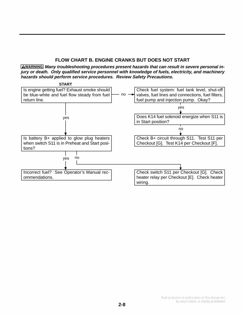
FLOW CHART B. ENGINE CRANKS BUT DOES NOT START
Is engine getting fuel? Exhaust smoke shouldbe blue-white and fuel flow steady from fuelreturn line.
Is battery B+ applied to glow plug heaterswhen switch S11 is in Preheat and Start posi-tions?
Incorrect fuel? See Operator’s Manual rec-ommendations.
Check fuel system: fuel tank level, shut-offvalves, fuel lines and connections, fuel filters,fuel pump and injection pump. Okay?
Does K14 fuel solenoid energize when S11 isin Start position?
Check B+ circuit through S11. Test S11 perCheckout [G]. Test K14 per Checkout [F].
Check switch S11 per Checkout [G]. Checkheater relay per Checkout [E]. Check heaterwiring.
no
no
yes
yes
yes
START
no
WARNING
2-9
Many troubleshooting procedures present hazards that can result in severe personal in-jury or death. Only qualified service personnel with knowledge of fuels, electricity, and machineryhazards should perform service procedures. Review Safety Precautions.
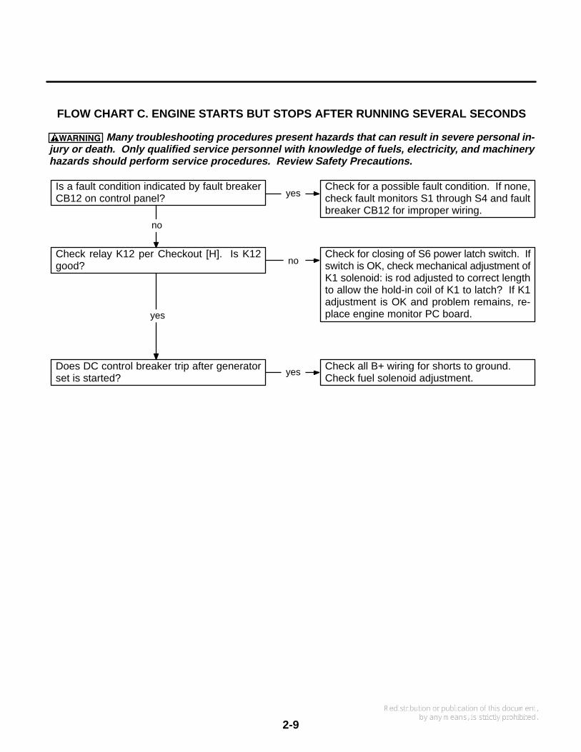
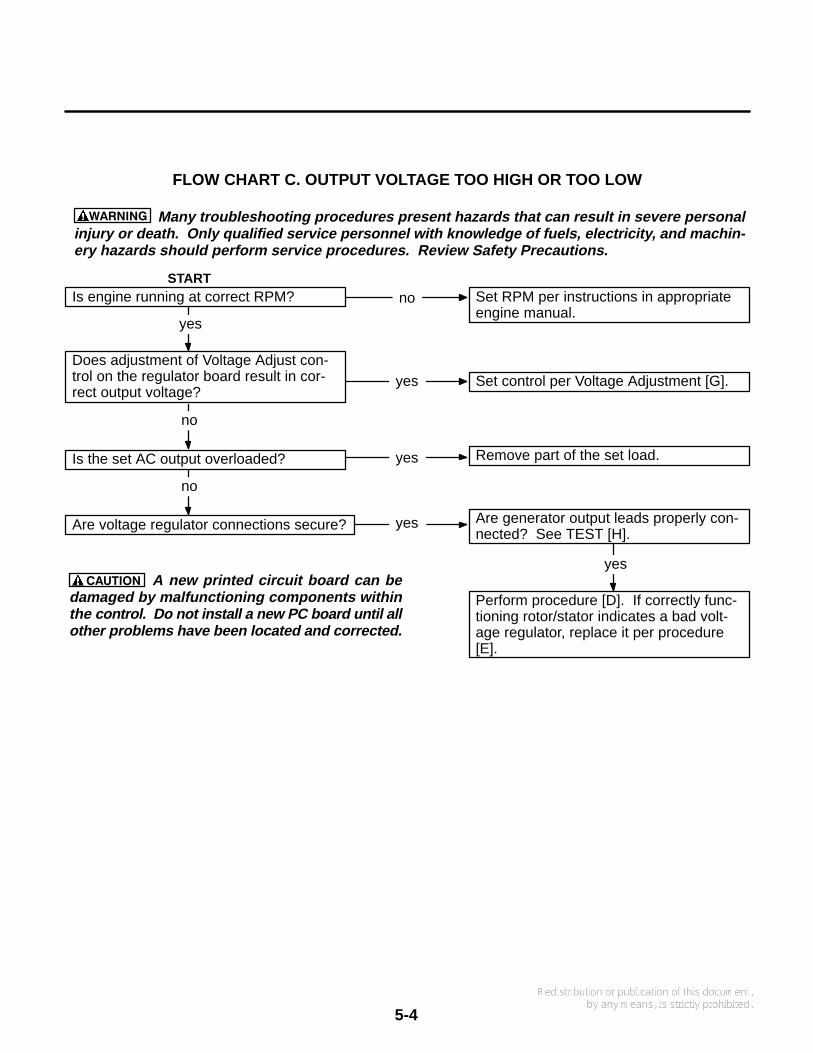
FLOW CHART C. ENGINE STARTS BUT STOPS AFTER RUNNING SEVERAL SECONDS
Is a fault condition indicated by fault breakerCB12 on control panel?
Check for a possible fault condition. If none,check fault monitors S1 through S4 and faultbreaker CB12 for improper wiring.
Check relay K12 per Checkout [H]. Is K12good?
Does DC control breaker trip after generatorset is started?
Check for closing of S6 power latch switch. Ifswitch is OK, check mechanical adjustment ofK1 solenoid: is rod adjusted to correct lengthto allow the hold-in coil of K1 to latch? If K1adjustment is OK and problem remains, re-place engine monitor PC board.
Check all B+ wiring for shorts to ground.Check fuel solenoid adjustment.
yes
yes
no
yes
no
WARNING

2-10
Blank Page
3. Engine Control Service
3-1
GENERAL
The following checks are referred to in the ControlTroubleshooting flow charts. They isolate circuitproblems caused by faulty engine control compo-nents. Disconnect leads before testing compo-nents.
WARNING Many troubleshooting procedurespresent hazards that can result in severe per-sonal injury or death. Only qualified servicepersonnel with knowledge of fuels, electricity,and machinery hazards should perform serviceprocedures. Review Safety Precautions.
[A]
BATTERY CHECK (BT1)
Check the battery charge condition with a hydrome-ter. Electrolyte specific gravity should be about1.260 for a fully charged battery at 80°F (27°C). Ifnot, add distilled water to keep electrolyte at properlevel, then recharge the battery. If the battery willnot recharge, replace it.
If the battery loses excess water, the charge ratemay be too high. If the battery charge is not main-tained, the charge rate may be too low. See proce-dure [C].
WARNING Ignition of explosive battery gasescan cause severe personal injury. Do not permitany flame, spark, cigarette, or other ignitionsource near the battery.
[B]
BATTERY CABLE CHECK
With the starter motor running, check these voltagedrops:
1. From the battery negative post (not the cableclamp) to the cylinder block
2. From the battery positive post to the battery ter-minal stud on the solenoid
Normally these should be less than 0.3 volts. If ex-tra-long battery cables are used, slightly higher volt-age drops may result. Thoroughly clean all connec-tions in any part of the circuit showing excessivevoltage drop.
[C]
BATTERY CHARGING CHECK
With the engine running, check the DC voltmeter(control option). The 12-volt system should read13.5 to 15 volts.
The power source is a belt-driven alternator. Thecharge rate/voltage is determined by a voltage reg-ulator located inside the control box.
Improper output may be caused by a loose drivebelt, poor terminal connections, broken wires, badregulator or alternator. Checkout procedures forthe regulator and alternator are found in the engineservice manual. The charge circuit is protected bycircuit breaker CB13.
If the output voltage is high (over 15 volts), check forloose or corroded voltage regulator leads. If thisdoes not correct the problem, the regulator is prob-ably shorted and should be replaced.
[D]
START SOLENOID CHECK (K11)
1. Apply battery positive (B+) to the terminalmarked S.
2. Connect a ground wire to the solenoid terminalmarked I. The solenoid should activate.
3. If the contacts are good, battery voltage shouldbe read between terminal 1 and ground. Thevoltage drop measured across the contactsshould never exceed one volt in circuit applica-tion.
3-2
[E]
HEATER (GLOW PLUG) RELAY CHECK(K13)
1. Connect the relay coil voltage across the relaycoil terminals. The relay should activate if coilis okay.
2. Connect a voltage source to one side of relaycontacts.
3. Connect a voltmeter to other side of relay con-tact and voltage source. If voltage appearswhen relay energizes, the contact is good. Thevoltage reading appears in reverse order whenchecking normally closed (NC) contacts.
[F]
FUEL SOLENOID CHECK (K14)
If there is fuel to the injection pump, but no fuel at theinjection nozzle, the fuel solenoid may be defective.
To check solenoid operation, watch for solenoid ac-tuation when B+ is applied (start switch in start orrun position). If there is no actuation when B+ is ap-plied, the fuel solenoid must be replaced. When B+is removed, the solenoid must de-activate.
[G]
START/STOP SWITCH CHECK (S11)
1. Remove battery B+ cable.
2. Place ohmmeter leads across switch.
3. Open and close switch while observing theohmmeter. A normally open (NO) switchshould indicate infinite resistance when openand continuity when closed. A normally closed(NC) switch should indicate continuity whenclosed and infinite resistance when open.
4. Replace switch if defective.
[H]
POWER RELAY CHECK (A11-K12)
Make certain that the genset starting battery is goodbefore beginning this check.
1. Unplug CB12-2A from the circuit breaker. Notethe markings on the wire to select the correctone.
2. Locate S6 (oil pressure switch) on the genset(see Figure 2-2). Find the grounded side of S6,using a continuity tester.
3. Use a jumper to ground the non-grounded sideof S6.
4. Use a second jumper from the B+ terminal onthe control board to apply B+ to the SW B+(switched B+) terminal. Fuel pump E5 shouldstart and run.
5. Remove the B+ jumper. If the fuel pump contin-ues to run, K12 is good. If the fuel pump stops,K12 has failed and the A11 control boardshould be replaced.
6. Push the genset STOP button.
7. Remove the jumpers and reconnect CB12-2A.
4. Generator/Voltage Regulator
4-1
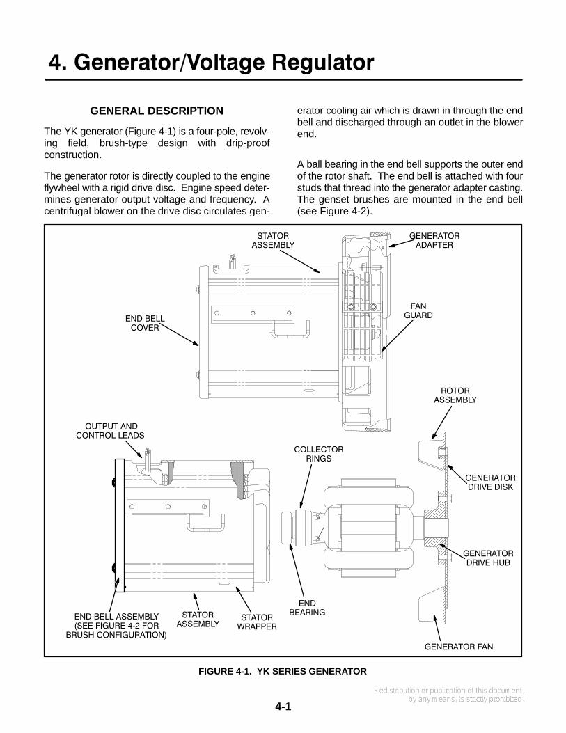
GENERAL DESCRIPTION
The YK generator (Figure 4-1) is a four-pole, revolv-ing field, brush-type design with drip-proofconstruction.
The generator rotor is directly coupled to the engineflywheel with a rigid drive disc. Engine speed deter-mines generator output voltage and frequency. Acentrifugal blower on the drive disc circulates gen-
erator cooling air which is drawn in through the endbell and discharged through an outlet in the blowerend.
A ball bearing in the end bell supports the outer endof the rotor shaft. The end bell is attached with fourstuds that thread into the generator adapter casting.The genset brushes are mounted in the end bell(see Figure 4-2).
FIGURE 4-1. YK SERIES GENERATOR
STATORASSEMBLY
GENERATORADAPTER
FANGUARDEND BELL
COVER
OUTPUT ANDCONTROL LEADS
COLLECTORRINGS
GENERATORDRIVE DISK
GENERATORDRIVE HUB
GENERATOR FAN
ROTORASSEMBLY
ENDBEARING
STATORWRAPPER
STATORASSEMBLY
END BELL ASSEMBLY(SEE FIGURE 4−2 FOR
BRUSH CONFIGURATION)

4-2
FIGURE 4-2. GENSET END BELL WITH BRUSHES
BRUSH BLOCKASSEMBLY
LEAD (F2 TOVR1−2)
LEAD (F1 TOVR1−1)
O−RING

4-3
FIGURE 4-3. SINGLE-PHASE GENERATOR SCHEMATIC
4-4
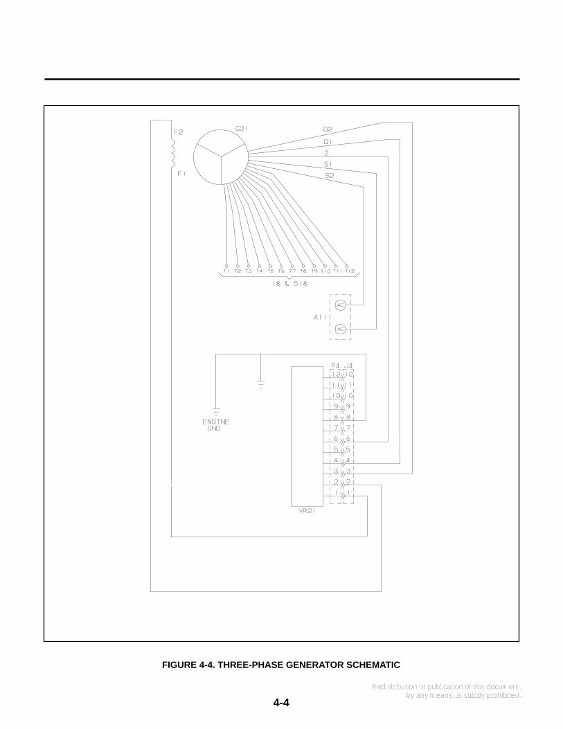
FIGURE 4-4. THREE-PHASE GENERATOR SCHEMATIC

4-5
GENERATOR OPERATION
Refer to Figures 4-3 and 4-4, the generator sche-matics, while working through the following descrip-tion.
1. Voltage regulator VR1 (three-phase: VR21)supplies DC to the field winding (F1 - F2 leads)through brushes and slip rings, thereby estab-lishing a revolving 4-pole magnetic field. Thebattery is connected during startup to initiatefield excitation. Voltage regulator VR1 suppliesfield current during operation. Rated outputvoltage is maintained as the generator loadvaries, by varying field current to maintain fieldstrength proportional to the load.
2. The revolving magnetic field induces AC in thestator windings (T1 - T2 and T3 - T4) which areconnected to the load.
3. Under light load, the stator windings can supplysufficient current for the field to maintain ratedoutput voltage.
4. As the load increases, load currents increase,resulting in a proportional increase of current,
which in turn supplies the field. Rated outputvoltage is thereby maintained as the load var-ies.
ELECTRONIC VOLTAGE REGULATOR
The voltage regulator controls the output of the gen-erator so that a constant voltage is maintained un-der varying load conditions.
Only the basic functions of the regulator are de-scribed (Figure 4-5). Voltage from quadrature wind-ings Q1/Q2 supply power to the voltage regulator it-self. The voltage regulator in turn supplies an ex-citation voltage (F1/F2) that is directly proportionateto the output voltage (L1/L0) it senses. Anychanges in the generator output voltage produce acorresponding change in the excitation voltage pro-vided by the regulator.
On the HDKAG, the voltage regulator assembly in-cludes a potentiometer which enables a slight de-gree of output voltage adjustment. The voltage reg-ulator assembly contains no user-serviceableparts. If the assembly fails, it must be replaced.
FIGURE 4-5. ADJUSTMENTS ON GENSET VOLTAGE REGULATOR BOARD
VOLTAGE ADJUST: Trim pot adjusts outputvoltage level. Turn pot clockwise to increasevoltage. Turn pot counterclockwise todecrease voltage.
BOARD SHOWNWITHOUT COVER

4-6
GENERATOR SERVICE
Always disconnect the battery cables (negative [-]first) from the battery to prevent accidental startingof the set while servicing the generator.
WARNING Accidental starting of the set whileworking on it can cause severe injury. To pre-vent accidental starting, disconnect the batterycables (negative [-] first) from the battery.
The negative (-) cable is always disconnectedfirst, and connected last, to prevent arcing if atool accidentally touches the frame or othergrounded metal parts of the set while discon-necting or connecting the positive (+) cable.Arcing can ignite the explosive hydrogen gasgiven off by the battery, and cause severe inju-ry.
Brush Inspection/Replacement
The generator should be inspected for brush wearand cleaning every six months.
WARNING Accidental starting of the generatorset can cause severe personal injury or death.Stop the generator set and disable by discon-necting the starting battery cables (negative [-]cable first) before inspecting the generator.
1. Remove the access cover for the brush assem-bly.
2. Check the brushes for wear with a piece of wiremarked off 1 inch (25 mm) from one end (Fig-ure 4-6). Replace the brush and the spring ifthe wire goes into the brush holder 1 inch ormore.
3. To replace brushes, remove the brush holderby disconnecting the two leads to the holderand removing the two mounting screws.
4. Install the new brushes and springs in the hold-er and keep them in place during assembly byinserting a piece of wire through the holder, asshown in Figure 4-7.
5. Install the brush holder. After tightening themounting screws, pull out the brush retainingwire.
6. Connect the F1 lead to the inner brush terminal(nearest the rotor windings). Connect the F2lead to the outer brush terminal (nearest theend bell).
Slip Ring Inspection/Replacement
Inspect the slip rings for grooves, pits or other dam-age. If dust has accumulated on any generatorcomponents, they can be cleaned with filtered low-pressure air.
1. Examine the slip rings while servicing thebrushes.
2. If the rings need cleaning or service, removethe rotor from the generator and dress the ringson a lathe.
CAUTION Dressing the slip rings on a latheimproperly may damage the generator rotor.Make certain that only an experienced techni-cian performs this job.
Generator Bearing
Inspect the bearing for evidence of outer case rota-tion every 1000 hours of use. The bearing shouldbe replaced every five years, because the bearinggrease gradually deteriorates due to oxidation.
Replace the O-ring if it shows evidence of wear ordeterioration. Renew grease if necessary (molyonly).

4-7
ES1676
BRUSH BLOCKASSEMBLY
MEASURINGWIRE
GENERATORBEARING
1 INCH
FIGURE 4-6. CHECKING GENERATOR BEARINGAND BRUSH BLOCK
WIRE
HOLDER
SPRING BRUSH
FIGURE 4-7. BRUSH REPLACEMENT
4-8
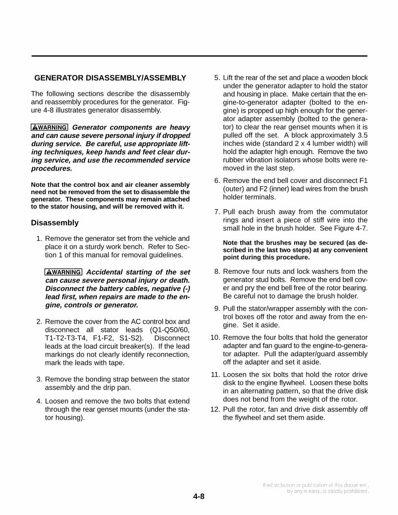
GENERATOR DISASSEMBLY/ASSEMBLY
The following sections describe the disassemblyand reassembly procedures for the generator. Fig-ure 4-8 illustrates generator disassembly.
WARNING Generator components are heavyand can cause severe personal injury if droppedduring service. Be careful, use appropriate lift-ing techniques, keep hands and feet clear dur-ing service, and use the recommended serviceprocedures.
Note that the control box and air cleaner assemblyneed not be removed from the set to disassemble thegenerator. These components may remain attachedto the stator housing, and will be removed with it.
Disassembly
1. Remove the generator set from the vehicle andplace it on a sturdy work bench. Refer to Sec-tion 1 of this manual for removal guidelines.
WARNING Accidental starting of the setcan cause severe personal injury or death.Disconnect the battery cables, negative (-)lead first, when repairs are made to the en-gine, controls or generator.
2. Remove the cover from the AC control box anddisconnect all stator leads (Q1-Q50/60,T1-T2-T3-T4, F1-F2, S1-S2). Disconnectleads at the load circuit breaker(s). If the leadmarkings do not clearly identify reconnection,mark the leads with tape.
3. Remove the bonding strap between the statorassembly and the drip pan.
4. Loosen and remove the two bolts that extendthrough the rear genset mounts (under the sta-tor housing).
5. Lift the rear of the set and place a wooden blockunder the generator adapter to hold the statorand housing in place. Make certain that the en-gine-to-generator adapter (bolted to the en-gine) is propped up high enough for the gener-ator adapter assembly (bolted to the genera-tor) to clear the rear genset mounts when it ispulled off the set. A block approximately 3.5inches wide (standard 2 x 4 lumber width) willhold the adapter high enough. Remove the tworubber vibration isolators whose bolts were re-moved in the last step.
6. Remove the end bell cover and disconnect F1(outer) and F2 (inner) lead wires from the brushholder terminals.
7. Pull each brush away from the commutatorrings and insert a piece of stiff wire into thesmall hole in the brush holder. See Figure 4-7.
Note that the brushes may be secured (as de-scribed in the last two steps) at any convenientpoint during this procedure.
8. Remove four nuts and lock washers from thegenerator stud bolts. Remove the end bell cov-er and pry the end bell free of the rotor bearing.Be careful not to damage the brush holder.
9. Pull the stator/wrapper assembly with the con-trol boxes off the rotor and away from the en-gine. Set it aside.
10. Remove the four bolts that hold the generatoradapter and fan guard to the engine-to-genera-tor adapter. Pull the adapter/guard assemblyoff the adapter and set it aside.
11. Loosen the six bolts that hold the rotor drivedisk to the engine flywheel. Loosen these boltsin an alternating pattern, so that the drive diskdoes not bend from the weight of the rotor.
12. Pull the rotor, fan and drive disk assembly offthe flywheel and set them aside.

4-9
FIGURE 4-8. GENERATOR DISASSEMBLY/REASSEMBLY
STUD BOLT(1 OF 4)
BRUSHBLOCK
ENGINE−GENERATORADAPTER
ROTORASSEMBLY
STATORASSEMBLY
END BELLCOVER
SPRING
BRUSH
O−RING
xES2095s
END BELLASSEMBLY
ENDBEARING
FAN
MOUNTINGFOOT

4-10
Rotor Disassembly
1. Place the rotor assembly on a wood block in thehorizontal position. The drive disc and fanshould not be resting on anything, or dis-tortion may occur.
2. Remove the six bolts that hold the drive diskand fan to the rotor hub. Remove the drive diskand fan.
3. Use a gear puller to remove the end bearingfrom the rotor shaft.
CAUTION The end bearing will be dam-aged if pulled on the outer race. If the bear-ing must be removed, replace it; this bear-ing should not be reused.
Rotor Bearing Replacement
1. Clean the bearing and shaft mating surfaces.
2. Apply Loctite #680 adhesive to the shaft matingsurface.
3. Apply Loctite #747 activator to the bearing mat-ing surface.
4. Install the bearing and allow ten minutes curingtime before handling the assembly.
Rotor Reassembly
After necessary service checks and repairs aremade, the rotor and generator are reassembled us-ing the reverse procedure of disassembly except forthe rotor as noted below. Regrease the O-ring us-ing moly grease only. Apply required torque valueshown in Figure 4-9.
CAUTION The drive disk will be damaged if thebolts are tightened and it is not properly cen-tered. Center the disk accurately before begin-ning to tighten the drive disk.

4-11
REMOVE SIX BOLTS ANDWASHERS TO REMOVE DRIVEDISK FROM HUB: TORQUE TO25−29 N−M WHEN REPLACING
FIGURE 4-9. ROTOR ASSEMBLY COMPONENTS
COLLECTORRINGS
GENERATORDRIVE DISK
GENERATORDRIVE HUB
GENERATORFAN
ROTORASSEMBLY
ENDBEARING
ROTORWINDINGS

4-12
Blank Page
5-1
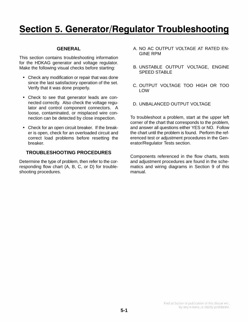
GENERAL
This section contains troubleshooting informationfor the HDKAG generator and voltage regulator.Make the following visual checks before starting:
• Check any modification or repair that was donesince the last satisfactory operation of the set.Verify that it was done properly.
• Check to see that generator leads are con-nected correctly. Also check the voltage regu-lator and control component connectors. Aloose, contaminated, or misplaced wire con-nection can be detected by close inspection.
• Check for an open circuit breaker. If the break-er is open, check for an overloaded circuit andcorrect load problems before resetting thebreaker.
TROUBLESHOOTING PROCEDURES
Determine the type of problem, then refer to the cor-responding flow chart (A, B, C, or D) for trouble-shooting procedures.
A. NO AC OUTPUT VOLTAGE AT RATED EN-GINE RPM
B. UNSTABLE OUTPUT VOLTAGE, ENGINESPEED STABLE
C. OUTPUT VOLTAGE TOO HIGH OR TOOLOW
D. UNBALANCED OUTPUT VOLTAGE
To troubleshoot a problem, start at the upper leftcorner of the chart that corresponds to the problem,and answer all questions either YES or NO. Followthe chart until the problem is found. Perform the ref-erenced test or adjustment procedures in the Gen-erator/Regulator Tests section.
Components referenced in the flow charts, testsand adjustment procedures are found in the sche-matics and wiring diagrams in Section 9 of thismanual.
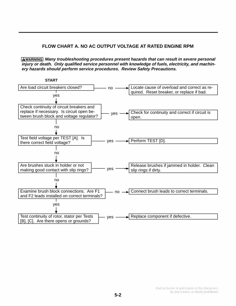
5-2
Many troubleshooting procedures present hazards that can result in severe personalinjury or death. Only qualified service personnel with knowledge of fuels, electricity, and machin-ery hazards should perform service procedures. Review Safety Precautions.
FLOW CHART A. NO AC OUTPUT VOLTAGE AT RATED ENGINE RPM
Are load circuit breakers closed? Locate cause of overload and correct as re-quired. Reset breaker, or replace if bad.
no
yes
START
Check continuity of circuit breakers andreplace if necessary. Is circuit open be-tween brush block and voltage regulator?
no
yes Check for continuity and correct if circuit isopen.
Are brushes stuck in holder or notmaking good contact with slip rings? yes
Release brushes if jammed in holder. Cleanslip rings if dirty.
no
Test continuity of rotor, stator per Tests[B], [C]. Are there opens or grounds?
yes Replace component if defective.
Test field voltage per TEST [A]. Isthere correct field voltage?
no
yes
Examine brush block connections. Are F1and F2 leads installed on correct terminals?
Perform TEST [D].
no Connect brush leads to correct terminals.
yes
WARNING
5-3
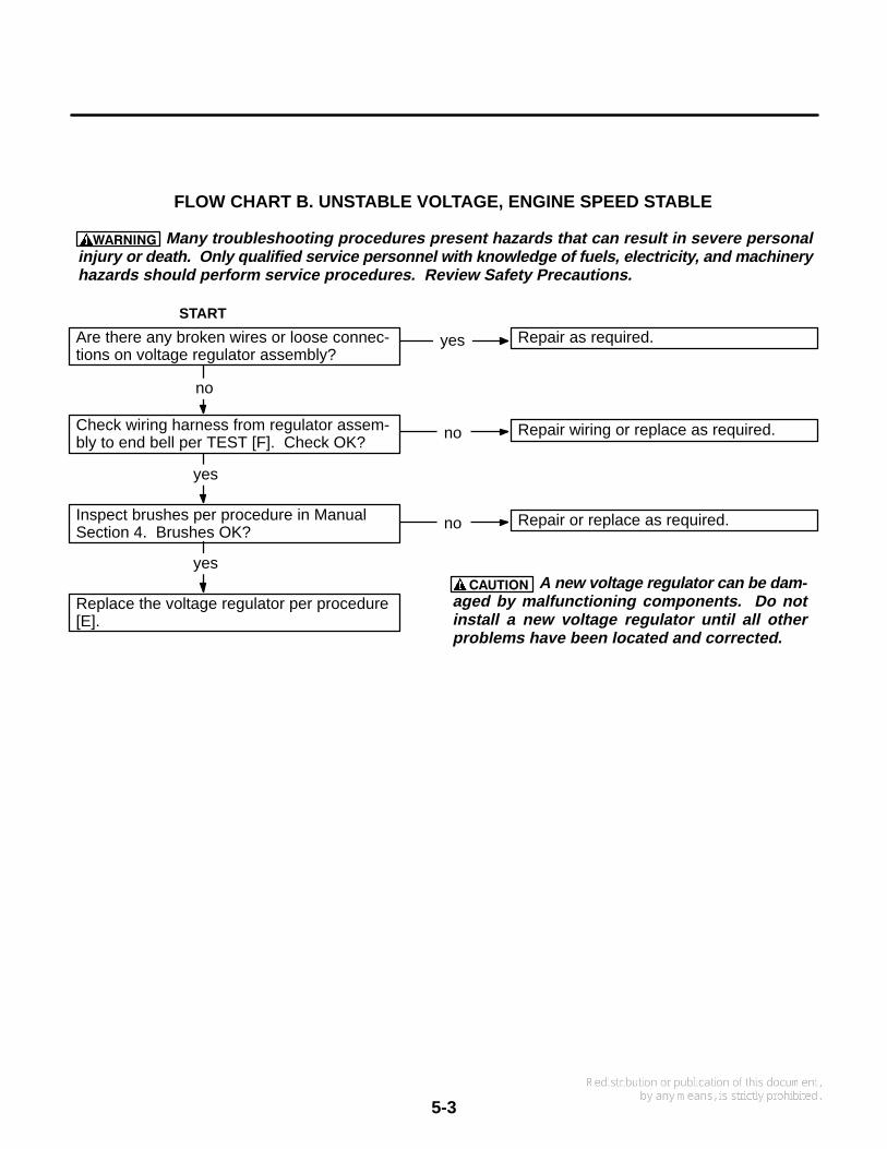
A new voltage regulator can be dam-aged by malfunctioning components. Do notinstall a new voltage regulator until all otherproblems have been located and corrected.
Many troubleshooting procedures present hazards that can result in severe personalinjury or death. Only qualified service personnel with knowledge of fuels, electricity, and machineryhazards should perform service procedures. Review Safety Precautions.
FLOW CHART B. UNSTABLE VOLTAGE, ENGINE SPEED STABLE
Are there any broken wires or loose connec-tions on voltage regulator assembly?
yes
Check wiring harness from regulator assem-bly to end bell per TEST [F]. Check OK?
Repair as required.
Inspect brushes per procedure in ManualSection 4. Brushes OK?
Repair wiring or replace as required.
no
yes
no
START
Replace the voltage regulator per procedure[E].
yes
Repair or replace as required.no
WARNING
CAUTION
5-4
Is engine running at correct RPM?
Does adjustment of Voltage Adjust con-trol on the regulator board result in cor-rect output voltage?
Are voltage regulator connections secure?
Set RPM per instructions in appropriateengine manual.
Set control per Voltage Adjustment [G].
Are generator output leads properly con-nected? See TEST [H].
Perform procedure [D]. If correctly func-tioning rotor/stator indicates a bad volt-age regulator, replace it per procedure[E].
Many troubleshooting procedures present hazards that can result in severe personalinjury or death. Only qualified service personnel with knowledge of fuels, electricity, and machin-ery hazards should perform service procedures. Review Safety Precautions.
FLOW CHART C. OUTPUT VOLTAGE TOO HIGH OR TOO LOW
A new printed circuit board can bedamaged by malfunctioning components withinthe control. Do not install a new PC board until allother problems have been located and corrected.
yes
yes
yes
yes
no
noSTART
Is the set AC output overloaded? Remove part of the set load.yes
no
CAUTION
WARNING

5-5
FLOW CHART D. UNBALANCED GENERATOR OUTPUT VOLTAGE
Many troubleshooting procedures present hazards that can result in severe personalinjury or death. Only qualified service personnel with knowledge of fuels, electricity, and machineryhazards should perform service procedures. Review Safety Precautions.
Remove load at generator terminals. Isoutput still unbalanced?
Are generator leads connected andgrounded properly? See Test [C].
Is generator stator winding continuousper TEST [C]?
Check load for ground faults and correctas necessary.
Check for correct grounding of generatorand load.
Correct as necessary.
Replace stator assembly.
START
yes
yes
yes
no
no
no
WARNING

5-6
Blank Page

Section 6. Generator/Regulator Tests
6-1
GENERAL
The following tests and adjustments can be per-formed without disassembly of the generator.These procedures should be used for testing thegenerator components and the regulator in con-junction with the Troubleshooting Flow Charts in theGenerator/Regulator Troubleshooting section.
WARNING Many troubleshooting procedurespresent hazards that can result in severe per-sonal injury or death. Only qualified servicepersonnel with knowledge of fuels, electricity,and machinery hazards should perform serviceprocedures. Review safety precautions on in-side cover page.
[A] TESTING FIELD VOLTAGE
Field voltage can be tested at the brush holder ter-minals with a DC voltmeter. Field voltage should fallbetween 18 and 60 volts. Test at no load and at fullload. See Figure 6-1.
FIGURE 6-1. FIELD VOLTAGE TEST POINTS
BRUSHBLOCK
ASSEMBLY
LEAD (F2TO VR1−2)
LEAD (F1TO VR1−1)
TEST POINTS
[B] TESTING GENERATOR ROTOR
The generator circuits can be tested without havingto disassemble the generator. It is recommendedthat an ohmmeter be used to check for open circuitsand an insulation resistance meter for grounded cir-cuits. An ohmmeter can be used to check forgrounded circuits, but it may not be able to detectmarginal insulation breakdown.
FIGURE 6-2. TESTING ROTOR FOR GROUNDS
MEGGER ORINSULATIONRESISTANCE
METER
ES2068s
CONNECT LEADSBETWEEN EACH RING
AND ROTOR SHAFT
Testing for Grounds
Check for grounds between each slip ring and therotor shaft, Figure 6-2. Use a Megger or insulationresistance meter which applies 500 VDC or more atthe test leads. Perform test as follows:
1. Isolate the rotor windings by disconnecting thetwo leads to the brush holder.
2. Connect test leads between each ring and therotor shaft in turn. Meter should register100,000 ohms or greater.
3. If less than 100,000 ohms, rotor is question-able. Thoroughly dry the rotor and retest.
4. Replace a grounded rotor with a new identicalpart.

6-2
Testing for Open or Shorted Windings
Perform this test with an accurate meter such as adigital ohmmeter.
1. Isolate the rotor windings by disconnecting thetwo leads to the brush holder.
2. Using ohmmeter, check resistance betweenF1 and F2 by connecting leads between the F1and F2 slip rings, Figure 6-3.
Rotor resistances (measured at 25° C) are:
Standard single-phase: 17.2 ohmsStandard three-phase: 19.4 ohmsExtended-stack three-phase: 22.5 ohmsExtended-stack three-phase “husky”:
25.5 ohms
If there is a large difference, replace the defec-tive rotor with a new, identical part.
FIGURE 6-3. TESTING ROTOR FOR ANOPEN CIRCUIT
CONNECT LEADS BETWEENF1, F2 SLIP RINGS
DIGITALOHMMETER
ES2069s
[C] TESTING GENERATOR STATOR
Isolate the stator windings by disconnecting all sixstator leads. Test for open circuits between T1-T2,T3-T4 and Q1-Q2, and for grounded circuits be-tween T1, T3 and B1 and the stator laminations orother unpainted grounding point.
Using proper test equipment, check the stator forgrounds, opens, and shorts in the windings.
Testing for Grounds
Some generators have ground connections to theframe. Check wiring diagram. All stator leads mustbe isolated for testing.
Use a megger or insulation resistance meter whichapplies not more than 500 VDC to the test leads(Figure 6-4). Test each stator winding for short tolaminations. A reading less than 100,000 ohms in-dicates a questionable stator. Thoroughly dry thestator and retest.
FIGURE 6-4. TESTING STATOR WINDINGFOR GROUNDS
ES2070s
CONNECT LEADS BETWEENEACH WINDING AND GROUND
6-3
Testing for Open or Shorted Windings
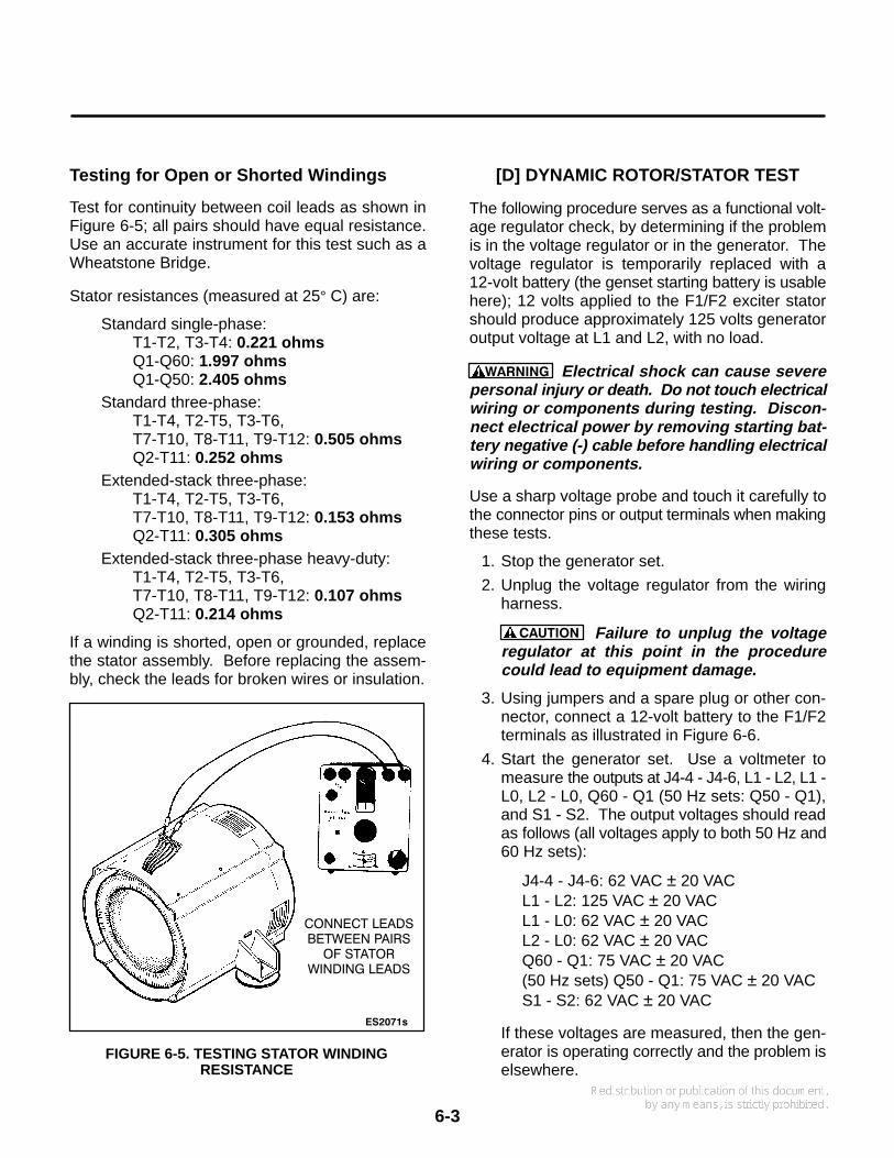
Test for continuity between coil leads as shown inFigure 6-5; all pairs should have equal resistance.Use an accurate instrument for this test such as aWheatstone Bridge.
Stator resistances (measured at 25° C) are:
Standard single-phase: T1-T2, T3-T4: 0.221 ohmsQ1-Q60: 1.997 ohmsQ1-Q50: 2.405 ohms
Standard three-phase: T1-T4, T2-T5, T3-T6,T7-T10, T8-T11, T9-T12: 0.505 ohmsQ2-T11: 0.252 ohms
Extended-stack three-phase:T1-T4, T2-T5, T3-T6,T7-T10, T8-T11, T9-T12: 0.153 ohmsQ2-T11: 0.305 ohms
Extended-stack three-phase heavy-duty:T1-T4, T2-T5, T3-T6,T7-T10, T8-T11, T9-T12: 0.107 ohmsQ2-T11: 0.214 ohms
If a winding is shorted, open or grounded, replacethe stator assembly. Before replacing the assem-bly, check the leads for broken wires or insulation.
ES2071s
FIGURE 6-5. TESTING STATOR WINDINGRESISTANCE
CONNECT LEADSBETWEEN PAIRS
OF STATORWINDING LEADS
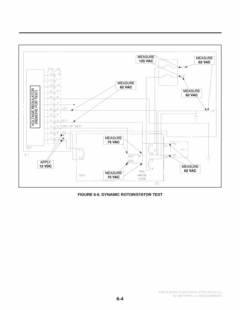
[D] DYNAMIC ROTOR/STATOR TEST
The following procedure serves as a functional volt-age regulator check, by determining if the problemis in the voltage regulator or in the generator. Thevoltage regulator is temporarily replaced with a12-volt battery (the genset starting battery is usablehere); 12 volts applied to the F1/F2 exciter statorshould produce approximately 125 volts generatoroutput voltage at L1 and L2, with no load.
WARNING Electrical shock can cause severepersonal injury or death. Do not touch electricalwiring or components during testing. Discon-nect electrical power by removing starting bat-tery negative (-) cable before handling electricalwiring or components.
Use a sharp voltage probe and touch it carefully tothe connector pins or output terminals when makingthese tests.
1. Stop the generator set.
2. Unplug the voltage regulator from the wiringharness.
CAUTION Failure to unplug the voltageregulator at this point in the procedurecould lead to equipment damage.
3. Using jumpers and a spare plug or other con-nector, connect a 12-volt battery to the F1/F2terminals as illustrated in Figure 6-6.
4. Start the generator set. Use a voltmeter tomeasure the outputs at J4-4 - J4-6, L1 - L2, L1 -L0, L2 - L0, Q60 - Q1 (50 Hz sets: Q50 - Q1),and S1 - S2. The output voltages should readas follows (all voltages apply to both 50 Hz and60 Hz sets):
J4-4 - J4-6: 62 VAC ± 20 VACL1 - L2: 125 VAC ± 20 VACL1 - L0: 62 VAC ± 20 VACL2 - L0: 62 VAC ± 20 VACQ60 - Q1: 75 VAC ± 20 VAC(50 Hz sets) Q50 - Q1: 75 VAC ± 20 VACS1 - S2: 62 VAC ± 20 VAC
If these voltages are measured, then the gen-erator is operating correctly and the problem iselsewhere.
6-4
+−
APPLY12 VDC
MEASURE75 VAC
MEASURE62 VAC
MEASURE75 VAC
MEASURE62 VAC
MEASURE125 VAC
MEASURE62 VAC
MEASURE62 VAC
FIGURE 6-6. DYNAMIC ROTOR/STATOR TEST

6-5
[E] VOLTAGE REGULATORREPLACEMENT
Use the following procedure for replacing the ACvoltage regulator assembly.
1. Stop the generator set and disconnect thestarting battery leads, negative (-) lead first.
2. Unscrew the voltage regulator from the controlbox.
3. Disconnect the regulator from the wiring har-ness.
4. Remove the mounting screws from the old volt-age regulator, then install the new regulator.
5. Reconnect the plug connection to the wiringharness.
6. Set voltage as outlined in [G] Voltage Adjust-ment.
[F]
WIRING HARNESS CHECK
Carefully check the wiring harness as follows:
1. Inspect all wires for breaks, loose connections,and reversed connections. Refer to applicablewiring diagram.
2. Remove wires from terminals at each end andwith an ohmmeter, check each wire end to endfor continuity or opens.
3. Using an ohmmeter, check each wire to otherwires and to ground for possible shorts or in-sulation breaks under areas covered by wrap-ping material.
4. Reconnect or replace wires/harness accordingto applicable wiring diagram.
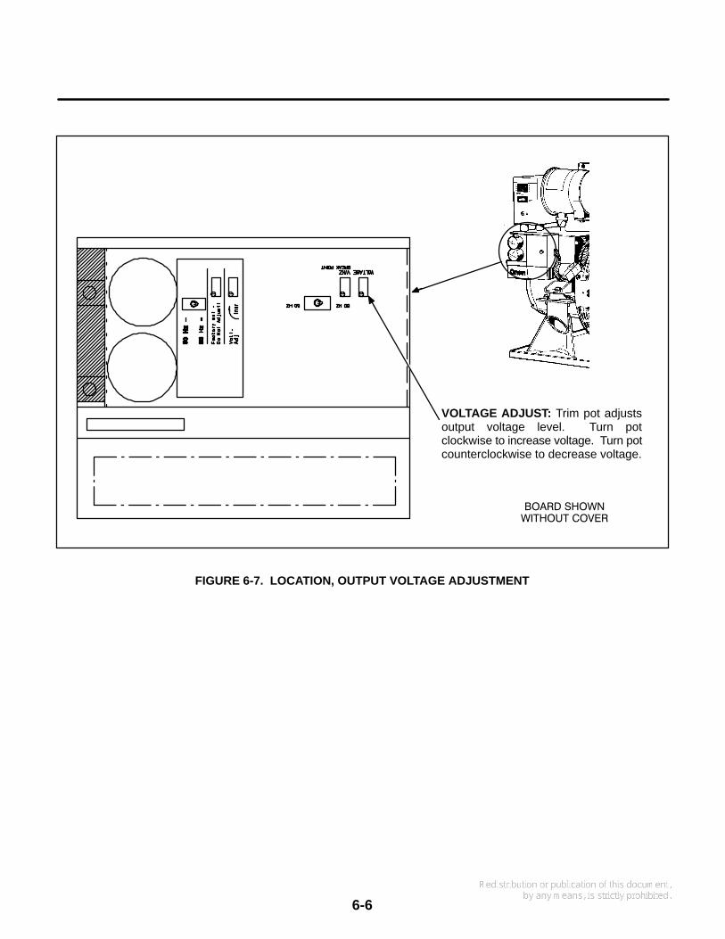
[G]
VOLTAGE ADJUSTMENT
This section describes adjustment of the gensetoutput voltage. When checking output voltage, be
sure the generator set has stabilized and is runningat the correct speed (frequency). The regulator isadjusted with the set running.
WARNING Accidental starting of the set cancause severe personal injury or death. Discon-nect both battery cables, negative (-) cable first,when repairs are made to the engine, controls,or generator.
WARNING Contact with high voltage can causesevere personal injury or death. Do not touchany exposed wiring or components with anypart of the body, clothing, tool or jewelry. Do notuse non-insulated tools inside the control.Stand on an insulating mat or dry wood platformwhen the control doors are open.
Output voltage adjustments are found on the volt-age regulator board under the DC control box. A re-movable cover protects the board. See Figure 6-7.
1. Attach a voltmeter securely to the L1 and L2leads.
2. Start the generator set and place a typical loadon its output.
3. Use a flat-blade screwdriver to set the voltageadjust potentiometer for correct voltage.
For most 60 Hz applications, the ideal setting is 117VAC at 60-61 hz, measured at the power input of theapplication. Retighten the locking nut when com-plete.
Note that the voltage adjustment pot on the voltageregulator board is a 10-turn potentiometer: it maytake several turns to change the voltage noticeably.
[H]
RECONNECTION
Generator reconnection is dependent upon thenameplate code. See Section 8 for reconnectiondiagrams.
6-6
FIGURE 6-7. LOCATION, OUTPUT VOLTAGE ADJUSTMENT
VOLTAGE ADJUST: Trim pot adjustsoutput voltage level. Turn potclockwise to increase voltage. Turn potcounterclockwise to decrease voltage.
BOARD SHOWNWITHOUT COVER
Section 7. Routine Maintenance
7-1
INTRODUCTION
This section describes routine maintenance proce-dures to be performed on the generator set. Most ofthis information is duplicated in the Operator’sManual, publication #981-0137.
Many of the items in this section refer to the gensetengine: for more information, refer to the EngineWorkshop Manual.
MAINTENANCE SCHEDULE
Perform each maintenance procedure at the timeperiod indicated or after the number of operating
hours indicated, whichever comes first. Refer to theMaintenance Procedures section for instructions. Ifthe generator set will be subjected to extremely hotor dusty conditions, a more frequent maintenanceschedule may be necessary.
WARNING Accidental starting of the generatorset during maintenance can cause severe per-sonal injury or death. Disconnect both genera-tor set starting battery cables, before perform-ing maintenance. Remove the negative (-) cablefirst to reduce the risk of arcing.
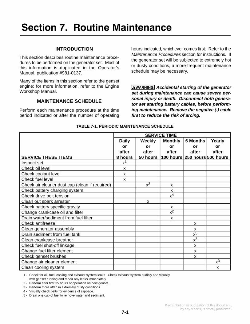
SERVICE TIMEDaily Weekly Monthly 6 Months Yearly
or or or or orafter after after after after
SERVICE THESE ITEMS 8 hours 50 hours 100 hours 250 hours 500 hoursInspect set x1
Check oil level xCheck coolant level xCheck fuel level xCheck air cleaner dust cap (clean if required) x3 xCheck battery charging system xCheck drive belt tension x4
Clean out spark arrester xCheck battery specific gravity xChange crankcase oil and filter x2
Drain water/sediment from fuel filter xCheck antifreeze xClean generator assembly xDrain sediment from fuel tank x5
Clean crankcase breather x3
Check fuel shut-off linkage xChange fuel filter element xCheck genset brushes xChange air cleaner element x3
Clean cooling system x
1 - Check for oil, fuel, cooling and exhaust system leaks. Check exhaust system audibly and visuallywith genset running and repair any leaks immediately.
2 - Perform after first 35 hours of operation on new genset.3 - Perform more often in extremely dusty conditions.4 - Visually check belts for evidence of slippage.5 - Drain one cup of fuel to remove water and sediment.
TABLE 7-1. PERIODIC MAINTENANCE SCHEDULE
7-2
GENERATOR SET INSPECTION
Inspect the generator set daily or after every eighthours of operation, whichever comes first. Checkthe exhaust, fuel, and DC electrical systems as de-scribed below. Also check the mechanical condi-tion of the set.
Engine Gauges (Remote Installation)
Check these gauges while the set is running.
Oil Pressure Gauge: Oil pressure should be 40 to60 psi (276 to 414 kPa) when the engine is at oper-ating temperature.
Coolant Temperature Gauge: Coolant tempera-ture should be 165° to 195° F (74° to 91° C), de-pending on load and ambient temperature.
DC Voltmeter: Battery voltage during operationshould be 14 to 15 volts.
Exhaust System
With the set running, inspect the entire exhaust sys-tem including the exhaust manifold, exhaust elbow,muffler and exhaust pipe. Visually and audiblycheck for leaks at all connections, welds, gaskets,and joints. If any leaks are detected, shut downthe genset and do not operate until corrected.Replace corroded exhaust components beforeleaks occur.
WARNING Inhalation of exhaust gases can re-sult in severe personal injury or death. Inspectexhaust system audibly and visually for leaksdaily. Repair all leaks immediately.
Fuel System
With the set running, inspect the fuel supply lines,return lines, filters, and fittings for leaks. Check flex-ible sections for cuts, cracks and abrasions. Seethat the fuel lines do not rub against anything thatcould break them. Replace worn fuel line compo-nents before leaks occur.
WARNING Fuel leakage will create a fire hazardwhich can result in severe personal injury ordeath if ignited. While checking for leaks, donot smoke or allow any spark, flame, pilot lightor other ignition source in the area. If any leaksare detected, have them corrected immediately.
DC Electrical System
With the genset off, check the battery terminals forclean and tight connections. Loose or corrodedconnections create resistance which can impedestarting. Clean and reconnect loose battery cables.Always disconnect the negative battery cable firstand connect it last, to reduce the possibility of arc-ing.
WARNING Ignition of explosive battery gasescan cause severe personal injury. Do notsmoke. W ear goggles, protective rubber glovesand apron when servicing batteries.
Mechanical
Check for any signs of mechanical damage. Startthe set and listen for any unusual noises that mayindicate mechanical problems.
Check the mounting fasteners to make sure the setis secure in its compartment. If an under-floor hous-ing is used, make sure that the set is secured to thehousing. Check the condition of the housing com-ponents and make sure they are secure to the ve-hicle.
Make sure that the generator set air inlet and outletareas are not blocked with debris.
Clean the generator set whenever dust and dirt be-gin to accumulate. Dust and dirt can usually be re-moved with a damp cloth. Steam cleaning may beneeded to remove road contaminants. Do not cleanthe genset while the engine is running. Protect thegenerator, air cleaner, control panel, and electricalconnections from cleaning solvents. Cleaning sol-vents can damage electrical connectors.

7-3
OIL AND FILTER CHANGE
Change the oil and filter at the intervals listed inTable 7-2. Use oil that meets the API classificationand SAE viscosity grade indicated in the previoussection.
Engine Oil Change
Run the engine until thoroughly warm. Stop the en-gine, open the drain valve (Figure 7-1) and drain theoil into a container. When completely drained, closethe valve and refill the crankcase with new oil.
WARNING Hot crankcase oil can cause burns ifit is spilled or splashed on skin. Keep fingersand hands clear when removing the oil drainplug and wear protective clothing.
WARNING State or federal agencies have de-termined that prolonged contact with used en-
gine oil can cause cancer or reproductive toxic-ity. When adding, changing or working withused oil, take care not to breathe, ingest orcome into excessive contact with these sub-stances. Wash hands after use. Wear protec-tive clothing and equipment. Provide adequateventilation.
Oil Filter Change
Spin off the oil filter and discard it. Thoroughly cleanthe filter mounting surface. Apply a thin film of oil tothe filter gasket, and spin the filter on until the gasketjust touches the mounting pad. Then turn an addi-tional 3/4 turn. Do not over-tighten the filter.
With oil in the crankcase, start the set and check forleakage around the filter gasket. Tighten the filteronly enough to eliminate leaks.
FIGURE 7-1. ENGINE OIL
OIL FILL
DRAINVALVE
OIL FILTEROIL
DIPSTICK
ALTERNATE OIL FILL ATTOP OF CYLINDER
HEAD COVER (HIDDEN)

7-4
COOLING SYSTEM
The cooling system must be filled with coolantbefore the genset can be operated. Cooling sys-tem capacity is listed in the Specifications section.
Coolant Requirements
Engine coolant must inhibit corrosion and protectagainst freezing. A 50/50 mixture of ethylene glycolanti-freeze and water is recommended for normaloperation and storage. Use only a reliable brand ofantifreeze that contains a rust and corrosion inhibi-tor. The antifreeze must not contain a stop-leakadditive.
Do not exceed a 50/50 mixture of ethylene glycoland water. A higher proportion of ethylene glycolwill alter the heat transfer properties of the coolant.A 50/50 mixture will provide freeze protection to-34° F (-37° C).
Water used for engine coolant should be clean, lowin minerals, and free of corrosive chemicals. Usedistilled or soft water if available. Avoid the use ofwell water, which may contain minerals that canclog the heat exchanger core and reduce cooling ef-ficiency.
Filling the Cooling System
Verify that all drain cocks are closed and all hoseclamps are secure. Remove the cooling systempressure cap and slowly fill the cooling system withthe coolant mixture.
CAUTION Exceeding the recommended fillrate can cause incomplete filling of the engineblock, leading to engine damage during warm-up. Always follow the recommended fill proce-dure.
Add coolant to the recovery tank (or separate ex-pansion tank if equipped) to the full-cold level.
Start the engine, then remove the pressure cap andmonitor the coolant level. As trapped air is expelledfrom the system, the coolant level will drop. Addcoolant to replace it. Replace the pressure capwhen the coolant level is stable.
Coolant Level
Check the coolant level at the intervals specified inthe Periodic Maintenance Schedule. Check by ob-serving the coolant level in the recovery tank (orseparate expansion tank if equipped) when the sys-tem is cold. See Figure 7-2 for a typical cooling sys-tem. Engine coolant is at the proper level when therecovery tank level is between FULL and LOWmarks.
WARNING Coolant in a warm engine is underpressure and can flash to steam causing severeburns if the radiator cap or drain cock areopened. Let the engine cool down before open-ing the radiator cap or drain cock.
CAUTION The high engine temperature cutoffwill shut down the engine in an overheat condi-tion only if the coolant level is sufficiently highto physically contact the shutdown switch.Loss of coolant will allow engine to overheatwithout protection of shutdown device, therebycausing severe damage to the engine. It istherefore imperative that adequate engine cool-ant levels be maintained for operational integri-ty of the cooling system and engine coolantoverheat shutdown protection.

7-5
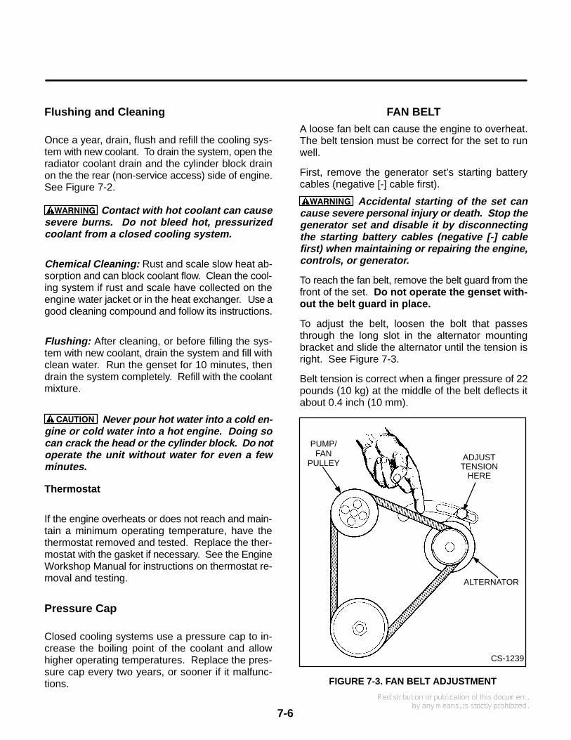
FIGURE 7-2. COOLING SYSTEM COMPONENTS
HOSE IS CONNECTED ATRADIATOR CAP
RECOVERYTANK
BRACKET
OVERFLOWHOSE
RADIATOR COOLANT DRAIN(ON LOWER REAR CORNER OF
RADIATOR)
CYLINDER BLOCK COOLANT DRAIN
(REAR OF GENSET ENGINE BLOCKSHOWN WITHOUT SHEET METAL, EX-
HAUST PARTS)
G1250s
7-6
Flushing and Cleaning
Once a year, drain, flush and refill the cooling sys-tem with new coolant. To drain the system, open theradiator coolant drain and the cylinder block drainon the the rear (non-service access) side of engine.See Figure 7-2.
WARNING Contact with hot coolant can causesevere burns. Do not bleed hot, pressurizedcoolant from a closed cooling system.
Chemical Cleaning: Rust and scale slow heat ab-sorption and can block coolant flow. Clean the cool-ing system if rust and scale have collected on theengine water jacket or in the heat exchanger. Use agood cleaning compound and follow its instructions.
Flushing: After cleaning, or before filling the sys-tem with new coolant, drain the system and fill withclean water. Run the genset for 10 minutes, thendrain the system completely. Refill with the coolantmixture.
CAUTION Never pour hot water into a cold en-gine or cold water into a hot engine. Doing socan crack the head or the cylinder block. Do notoperate the unit without water for even a fewminutes.
Thermostat
If the engine overheats or does not reach and main-tain a minimum operating temperature, have thethermostat removed and tested. Replace the ther-mostat with the gasket if necessary. See the EngineWorkshop Manual for instructions on thermostat re-moval and testing.
Pressure Cap
Closed cooling systems use a pressure cap to in-crease the boiling point of the coolant and allowhigher operating temperatures. Replace the pres-sure cap every two years, or sooner if it malfunc-tions.
FAN BELTA loose fan belt can cause the engine to overheat.The belt tension must be correct for the set to runwell.
First, remove the generator set’s starting batterycables (negative [-] cable first).
WARNING Accidental starting of the set cancause severe personal injury or death. Stop thegenerator set and disable it by disconnectingthe starting battery cables (negative [-] cablefirst) when maintaining or repairing the engine,controls, or generator.
To reach the fan belt, remove the belt guard from thefront of the set. Do not operate the genset with-out the belt guard in place.
To adjust the belt, loosen the bolt that passesthrough the long slot in the alternator mountingbracket and slide the alternator until the tension isright. See Figure 7-3.
Belt tension is correct when a finger pressure of 22pounds (10 kg) at the middle of the belt deflects itabout 0.4 inch (10 mm).
CS-1239
ADJUSTTENSION
HERE
ALTERNATOR
PUMP/FAN
PULLEY
FIGURE 7-3. FAN BELT ADJUSTMENT
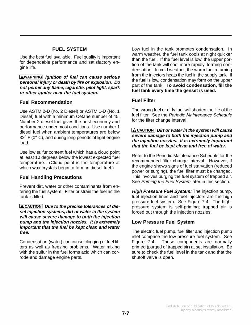
7-7
FUEL SYSTEM
Use the best fuel available. Fuel quality is importantfor dependable performance and satisfactory en-gine life.
WARNING Ignition of fuel can cause seriouspersonal injury or death by fire or explosion. Donot permit any flame, cigarette, pilot light, sparkor other igniter near the fuel system.
Fuel Recommendation
Use ASTM 2-D (no. 2 Diesel) or ASTM 1-D (No. 1Diesel) fuel with a minimum Cetane number of 45.Number 2 diesel fuel gives the best economy andperformance under most conditions. Use number 1diesel fuel when ambient temperatures are below32° F (0° C), and during long periods of light engineload.
Use low sulfur content fuel which has a cloud pointat least 10 degrees below the lowest expected fueltemperature. (Cloud point is the temperature atwhich wax crystals begin to form in diesel fuel.)
Fuel Handling Precautions
Prevent dirt, water or other contaminants from en-tering the fuel system. Filter or strain the fuel as thetank is filled.
CAUTION Due to the precise tolerances of die-sel injection systems, dirt or water in the systemwill cause severe damage to both the injectionpump and the injection nozzles. It is extremelyimportant that the fuel be kept clean and waterfree.
Condensation (water) can cause clogging of fuel fil-ters as well as freezing problems. Water mixingwith the sulfur in the fuel forms acid which can cor-rode and damage engine parts.
Low fuel in the tank promotes condensation. Inwarm weather, the fuel tank cools at night quickerthan the fuel. If the fuel level is low, the upper por-tion of the tank will cool more rapidly, forming con-densation. In cold weather, the warm fuel returningfrom the injectors heats the fuel in the supply tank. Ifthe fuel is low, condensation may form on the upperpart of the tank. To avoid condensation, fill thefuel tank every time the genset is used.
Fuel Filter
The wrong fuel or dirty fuel will shorten the life of thefuel filter. See the Periodic Maintenance Schedulefor the filter change interval.
CAUTION Dirt or water in the system will causesevere damage to both the injection pump andthe injection nozzles. It is extremely importantthat the fuel be kept clean and free of water.
Refer to the Periodic Maintenance Schedule for therecommended filter change interval. However, ifthe engine shows signs of fuel starvation (reducedpower or surging), the fuel filter must be changed.This involves purging the fuel system of trapped air.See Priming the Fuel System later in this section.
High Pressure Fuel System: The injection pump,fuel injection lines and fuel injectors are the highpressure fuel system. See Figure 7-4. The high-pressure system is self-priming; trapped air isforced out through the injection nozzles.
Low Pressure Fuel System
The electric fuel pump, fuel filter and injection pumpinlet comprise the low pressure fuel system. SeeFigure 7-4. These components are normallyprimed (purged of trapped air) at set installation. Besure to check the fuel level in the tank and that theshutoff valve is open.
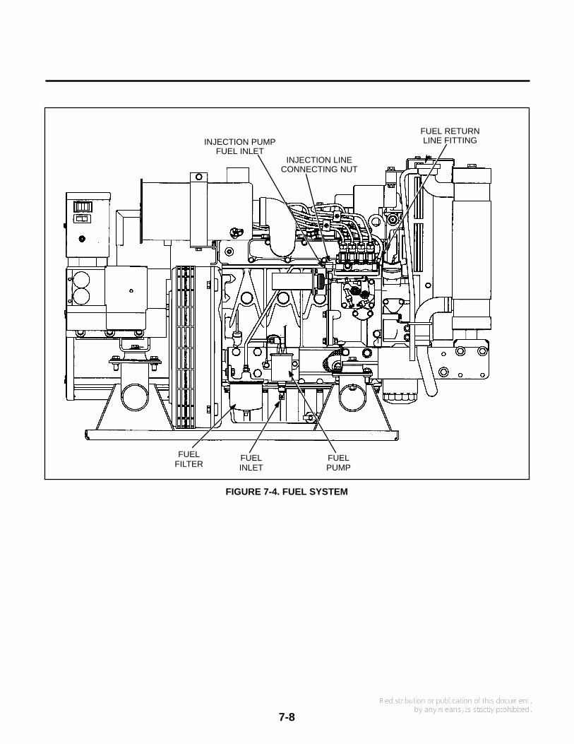
7-8
FUELINLET
FUELFILTER
FIGURE 7-4. FUEL SYSTEM
FUELPUMP
FUEL RETURNLINE FITTING
INJECTION LINECONNECTING NUT
INJECTION PUMPFUEL INLET
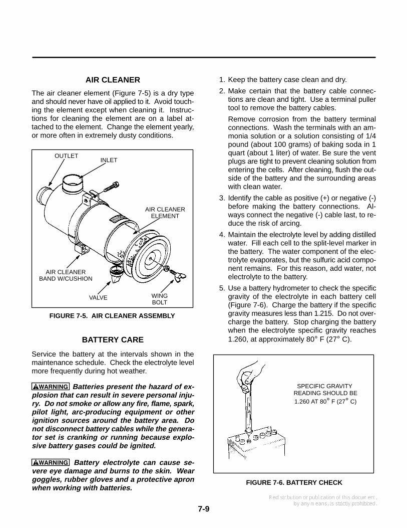
7-9
AIR CLEANER
The air cleaner element (Figure 7-5) is a dry typeand should never have oil applied to it. Avoid touch-ing the element except when cleaning it. Instruc-tions for cleaning the element are on a label at-tached to the element. Change the element yearly,or more often in extremely dusty conditions.
FIGURE 7-5. AIR CLEANER ASSEMBLY
AIR CLEANERBAND W/CUSHION
AIR CLEANERELEMENT
VALVE WINGBOLT
INLETOUTLET
BATTERY CARE
Service the battery at the intervals shown in themaintenance schedule. Check the electrolyte levelmore frequently during hot weather.
WARNING Batteries present the hazard of ex-plosion that can result in severe personal inju-ry. Do not smoke or allow any fire, flame, spark,pilot light, arc-producing equipment or otherignition sources around the battery area. Donot disconnect battery cables while the genera-tor set is cranking or running because explo-sive battery gases could be ignited.
WARNING Battery electrolyte can cause se-vere eye damage and burns to the skin. Weargoggles, rubber gloves and a protective apronwhen working with batteries.
1. Keep the battery case clean and dry.
2. Make certain that the battery cable connec-tions are clean and tight. Use a terminal pullertool to remove the battery cables.
Remove corrosion from the battery terminalconnections. Wash the terminals with an am-monia solution or a solution consisting of 1/4pound (about 100 grams) of baking soda in 1quart (about 1 liter) of water. Be sure the ventplugs are tight to prevent cleaning solution fromentering the cells. After cleaning, flush the out-side of the battery and the surrounding areaswith clean water.
3. Identify the cable as positive (+) or negative (-)before making the battery connections. Al-ways connect the negative (-) cable last, to re-duce the risk of arcing.
4. Maintain the electrolyte level by adding distilledwater. Fill each cell to the split-level marker inthe battery. The water component of the elec-trolyte evaporates, but the sulfuric acid compo-nent remains. For this reason, add water, notelectrolyte to the battery.
5. Use a battery hydrometer to check the specificgravity of the electrolyte in each battery cell(Figure 7-6). Charge the battery if the specificgravity measures less than 1.215. Do not over-charge the battery. Stop charging the batterywhen the electrolyte specific gravity reaches1.260, at approximately 80° F (27° C).
FIGURE 7-6. BATTERY CHECK
SPECIFIC GRAVITY READING SHOULD BE1.260 AT 80° F (27° C)

7-10
AC GENERATOR
Generator Brushes
The generator should be inspected for brush wearand cleaning as required per the Periodic Mainte-nance Schedule. Perform this procedure accordingto the steps in Section 4 of this manual.
WARNING Accidental starting of the generatorset can cause severe personal injury or death.Stop the generator set and disable by discon-necting the starting battery cables (negative [-]cable first before inspecting the generator.
Generator Bearing
Inspect the bearing for evidence of outer case rota-tion every 1000 hours of use. The bearing shouldbe replaced every five years, because the bearinggrease gradually deteriorates due to oxidation. SeeSection 4 of this manual for information on the gen-erator bearing.
CRANKCASE BREATHER
Clean the crankcase breather element at thescheduled intervals, using the following procedure(see Figure 7-7).
1. Remove the cap nuts and gaskets from the topof the cylinder head cover. Carefully removethe cover. Avoid damaging the gasket.
2. From inside the cover, remove two machinescrews securing the breather element, platesand shield.
3. Clean the element in a suitable solvent. Dry theelement, then saturate with engine oil before re-placing.
WARNING Many cleaning solvents presenta hazard of severe personal injury or death.Follow the manufacturer’s instructions andproceed with care.
4. If necessary, clean other breather componentsin solvent before reassembling.
CAP NUT ANDGASKET
FIGURE 7-7. CRANKCASE BREATHER
FILLER CAPAND GASKET
ELEMENTPLATE 1
BREATHERELEMENT
OILSHIELD
CYLINDERHEAD COVER
GASKET
BREATHERPIPE JOINT
BREATHERPIPEELEMENT
PLATE 2
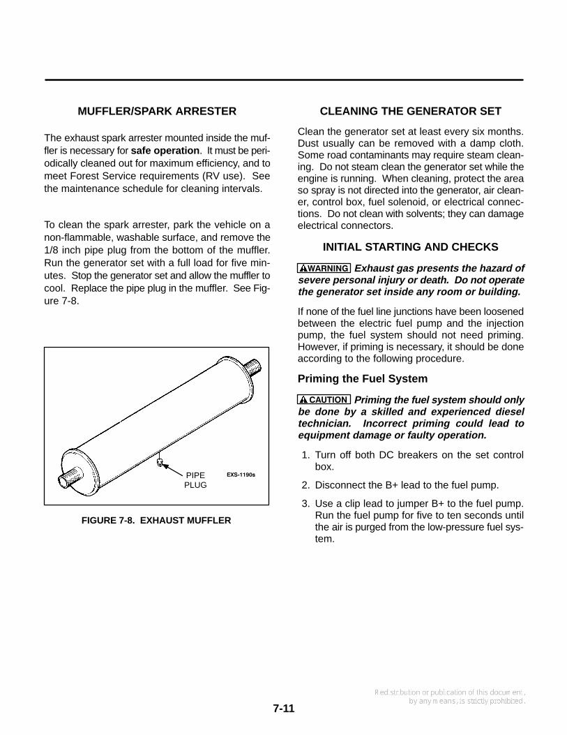
7-11
MUFFLER/SPARK ARRESTER
The exhaust spark arrester mounted inside the muf-fler is necessary for safe operation . It must be peri-odically cleaned out for maximum efficiency, and tomeet Forest Service requirements (RV use). Seethe maintenance schedule for cleaning intervals.
To clean the spark arrester, park the vehicle on anon-flammable, washable surface, and remove the1/8 inch pipe plug from the bottom of the muffler.Run the generator set with a full load for five min-utes. Stop the generator set and allow the muffler tocool. Replace the pipe plug in the muffler. See Fig-ure 7-8.
FIGURE 7-8. EXHAUST MUFFLER
EXS−1190sPIPEPLUG
CLEANING THE GENERATOR SET
Clean the generator set at least every six months.Dust usually can be removed with a damp cloth.Some road contaminants may require steam clean-ing. Do not steam clean the generator set while theengine is running. When cleaning, protect the areaso spray is not directed into the generator, air clean-er, control box, fuel solenoid, or electrical connec-tions. Do not clean with solvents; they can damageelectrical connectors.
INITIAL STARTING AND CHECKS
WARNING Exhaust gas presents the hazard ofsevere personal injury or death. Do not operatethe generator set inside any room or building.
If none of the fuel line junctions have been loosenedbetween the electric fuel pump and the injectionpump, the fuel system should not need priming.However, if priming is necessary, it should be doneaccording to the following procedure.
Priming the Fuel System
CAUTION Priming the fuel system should onlybe done by a skilled and experienced dieseltechnician. Incorrect priming could lead toequipment damage or faulty operation.
1. Turn off both DC breakers on the set controlbox.
2. Disconnect the B+ lead to the fuel pump.
3. Use a clip lead to jumper B+ to the fuel pump.Run the fuel pump for five to ten seconds untilthe air is purged from the low-pressure fuel sys-tem.

7-12
Blank Page
8. Wiring Diagrams
8-1
The electrical schematics and wiring diagrams that apply to the generator set covered in this manual are listedbelow.
WIRING DIAGRAM DRAWING NO. PAGE
DC Control Assembly 612-6635 8-2. . . . . . . . . . . . . . . . . . . . . . . . . . . . . . . . . . . . . . . . . . . . . . . .
AC Control Assembly (single-phase) 612-6637 8-3. . . . . . . . . . . . . . . . . . . . . . . . . . . . . . . . . . .
AC Control Assembly (three-phase) 612-6732 8-4. . . . . . . . . . . . . . . . . . . . . . . . . . . . . . . . . . .

8-2
612-6635

8-3
SEE NOTE 1
SEE NOTE 3
SEE NOTE 2
SEE NOTE 2
L1
L2
12
11
10
9
8
7
6
5
4
3
2
1
11
10
8
2
1
P4 J4
VR1
G1
3
4 ( Q1)
( Q50 OR Q60)
MAINARMATURESTATOR
A1
L1
L2
G1
P4/J4
A1
F2
S2
GND
1
VR1
F1
F2
T1
T2
T4
T3
Q60 Q1
F1
S1
T3
T4
T1
T2Q60Q1L0
L0
115/ 230
T4T3T2T1
L2L1 L0( N)
110/ 220230
T4T3T2T1
L0L1
220115
T4T2T3T1
L0L1
110
CBA HZ CODE
60
50 P
J
VO
LT
AG
ES
CH
EM
AT
IC
DI
AG
RA
M110 / 220V, 115/ 230V & 120/ 240V AS SHOWN
SEE RECONNECTI ON CHART FOR OTHER VOLTAGES
110/ 220V, 115/ 230V & 120/ 240V AS SHOWNSEE RECONNECTI ON CHART FOR OTHER VOLTAGES
L2
12
5
2
9
GND
S1
S2AC
AC
A11
6
2
3
4
5
6
12
11
10
9
8
7
Q50
2
7
( 2)
T4
T3
L0
L1
Q50 Q60T2
T1
S2
2
S1
Q1
T4
T3
L2
L1
Q50 Q60T2
T1
S2
2
S1
Q1
L0(N)
L1
Q50 Q60T2
T1
S2
2
S1
Q1
T4
T3
L0
Q50
120/ 240100/ 200
240200
120100
FIELD
GENERATOR
RECONNECTION CHART
WIRING DIAGRAM
SCHEMATIC
NOTE:
1. FROM J2-15 FOR FIELD FLASHING.
VOLTAGE REG- CAP AVR
LEAD ( F1)- -
PARTN0
REFDES
DWGSIZE QTY DESCRIPTION
VR1
21
3G1
---------------
- -- -- -- -
11
11
1GENERATORLEAD ( F2)
WI RE HARNESS
2. QUADRATURE POWER CONNECTION Q60-60 HZ, Q50-50 HZ UNITS.
3. AVR REFERENCE VOLTAGE.
612-6637
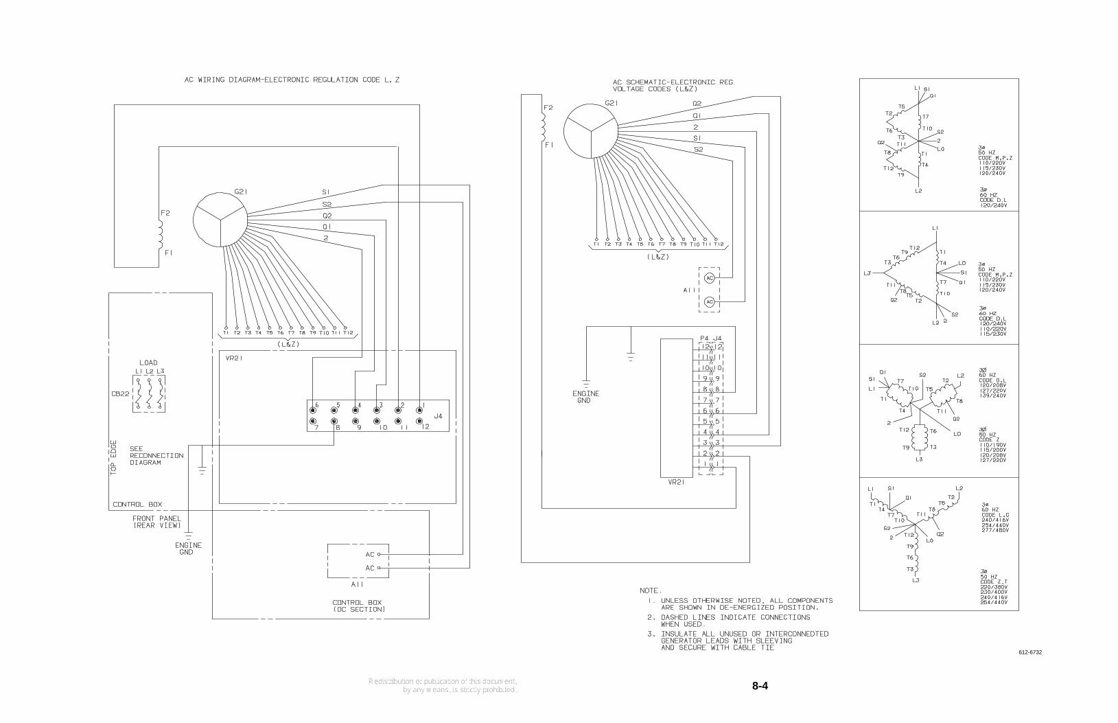
8-4
612-6732

Cummins Power Generation1400 73rd Avenue N.E.Minneapolis, MN 55432763-574-5000Fax: 763-528-7229
Cummins and Onan are registered trademarks of Cummins Inc.