Embed Size (px)
Citation preview
SM6-24
Medium Voltage Distribution
Modular units
Catalogue2010

A new path for achieving your electrical installations
A comprehensive offer
The SM6 range is part of a comprehensive offer of products that are perfectly coordinated to meet all medium and low voltage electrical distribution requirements. All of these products have been designed to work together: electrical, mechanical and communication compatibility.The electrical installation is thus both optimised and has improved performance:@ better service continuity,@ increased personnel and equipment safety,@ guaranteed upgradeability,@ effi cient monitoring and control.You therefore have all the advantages at hand in terms of know-how and creativity for achieving optimised, safe, upgradeable and compliant installations.
Tools for facilitating the design and installation
With Schneider Electric, you have a complete range of tools to help you get to know and install the products whilst complying with current standards and good working practices. These tools, technical sheets and guides, design software, training courses, etc are regularly updated.
For a real partnership with you
A universal solution doesn’t exist because each electrical installation is specifi c. The variety of combinations on offer allows you to truly customise the technical solutions.You are able to express your creativity and put your know-how to best advantage when designing, manufacturing and exploiting an electrical installation.
Schneider Electric is associating itself with your know-how and your creativity to produce optimised, safe, upgradeable and compliant installations

1AMTED398078EN.indd
SM6-24 General contents
Presentation 3
Generalities 11
Characteristics of the functional units 41
Connections 75
Installation 81
AppendicesOrder form 87

2 AMTED398078EN.indd
3AMTED398078EN.indd
SM6-24 Contents
PresentationThe experience of a world leader 4The range’s advantages 5Protecting the environment 6A full range of services 7The references of a leader 8Quality assurance 9

4 AMTED398078EN.indd
Presentation The experience of a world leaderM
T201
40 The Schneider Electric experience’s extends over forty years in factory-built cubicles and over thirty years in SF6 breaking technology for Medium Voltage switchgear. This experience means that today Schneider Electric can propose a complementary range: vacuum type circuit breaker cubicles up to 24 kV and internal arc cubicles to reinforced the safety of people according to the IEC standard.This gives you the advantage of unique experience, that of a world leader, with over 2,000 000 SF6 Medium Voltage units installed throughout the world.
Putting this experience at your service and remaining attentive to your requirements is the spirit of active partnership that we want to develop in offering you the SM6-24.
MT2
0141 The modular SM6-24 is a range of harmonised cubicles equipped
with SF6 or vacuum breaking technology switchgear with 30 years life span. These cubicles allow you to produce all your Medium Voltage substation requirements up to 24 kV by superposing their various functions.The result of in-depth analysis of your requirements, both now and in the future, SM6-24 cubicles mean that you can take advantage of all the features of both a modern and proven technology.
1975: innovation Sulphur hexafluoride (SF6) is first used in an MV switch for an MV/LV transformer substation, with the VM6.
1989: experience Over 300,000 VM6 cubicles equipped networks throughout the world.
1991: innovation and experience Cumulated with the second generation of SM6 modular SF6 cubicles.
2010: a leading position b with over 1,000,000 SM6-24 cubicles installed around the world, Schneider Electric consolidates its position as uncontested leader in the Medium Voltage field.
5AMTED398078EN.indd
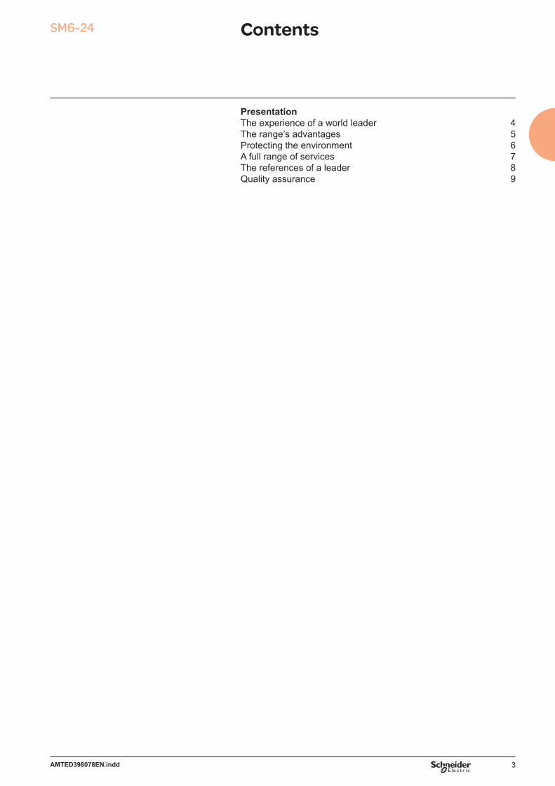
Presentation The range’s advantagesM
T201
42 UpgradabilitySM6-24, a comprehensive range
a comprehensive offer covering your present and future requirementsa design adapted to the extension of your installationsa catalogue of functions for all your applicationsa product designed to be in compliance with standards constraintsoptions to anticipate the telecontrol of your installations.
bbbbb
MT2
0143 Compactness
SM6-24, an optimised rangecompact units, with low increment cubiclesrationalised space requirement for switchboard installationreduction of civil works costseasy integration in factory-built outdoor substations for which the SM6-24
is particularly well designed.
bbbb
MT2
0144 Maintenance
SM6-24, a range with reduced maintenancethe active parts (breaking and earthing) are integrated in an SF6-filled, “sealed for
life” unitthe control mechanisms, are intented to function with reduced maintenance under
normal operating conditionsenhanced electrical endurance when breaking.
b
b
b
MT2
0145 Ease of installation
SM6-24, a simple range to incorporatereduced dimensions and weightsonly one civil works layouta solution adapted to cable connectionsimplified switchboard busbar design.
bbbb
MT2
0146 Ease and safe to operate
SM6-24, a proven rangea three position switch to block incorrect switchingthe earthing disconnector has full closing capacitypositive breaking of position indicatorsinternal arc withstand in the cable and switchgear compartmentsclear and animated display diagramsswitching lever with an “anti-reflex” functioncompartmented cubicles.
bbbbbbb
MT2
0147 SM6-24: a range designed with telecontrol in mind
SM6-24 switchgear is perfectly adapted to telecontrol applications. Motorised, either when installed or at a later date on-site without any interruption in service, SM6-24 combines with the Easergy T200 remote control interface. You therefore benefit from a ready-to connect unit that is easy to incorporate providing guaranteed switchgear operation.
MT2
0148 SM6-24: a range with adapted protection devices
With the SM6-24, Schneider Electric proposes solutions for network management; the Sepam and VIP or relay ranges protect installations, providing continuity of electrical supply and reducing downtime.

6 AMTED398078EN.indd
Presentation Protecting the environment
Schneider Electric’s recycling service for SF6 products is part of a rigorous management process.
6105
1N61
016N
MT5
5145
Schneider Electric is committed to a long term environmental approach. As part of this, the SM6-24 has been designed to be environmentally friendly, notably in terms of the product’s recycleability.The materials used, both conductors and insulators, are identified in product environmental profile analysis and easily separable. It was performed in conformity with ISO 14040 “Environmental management: life cycle assessment - principle and framework”.At the end of its life, SM6-24 can be processed, recycled and its materials recovered in conformity with the draft European regulations on the end-of-life of electronic and electrical products, and in particular withoutany gas being released to the atmosphere nor any polluting fluids being discharged.
The environmental management system adopted by Schneider Electric production sites that produce the SM6-24 have been assessed and judged to be in conformity with requirements in the ISO 14001 standard.
ISO 14001
Product environmental profile & recycling service
Switch unit
Circuit breaker unit
Ferrous metal 84% 65%
Non-ferrous metal 4% 10.6%
Thermohardening 9.5% 22%
Thermoplastics 2.35% 2.3%Fluid 0.15% 0.1%
7AMTED398078EN.indd
PE
5715
1
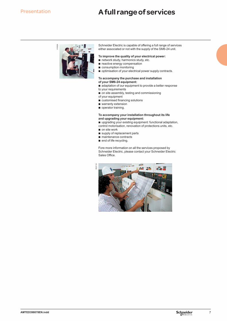
Presentation A full range of services
6105
2N Schneider Electric is capable of offering a full range of services either associated or not with the supply of the SM6-24 unit.
To improve the quality of your electrical power:network study, harmonics study, etc.reactive energy compensationconsumption monitoringoptimisation of your electrical power supply contracts.
To accompany the purchase and installation of your SM6-24 equipment:
adaptation of our equipment to provide a better responseto your requirements
on site assembly, testing and commissioning of your equipment
customised financing solutionswarranty extensionoperator training.
To accompany your installation throughout its life and upgrading your equipment:
upgrading your existing equipment: functional adaptation, control motorisation, renovation of protections units, etc.
on site worksupply of replacement partsmaintenance contracts end of life recycling.
Fore more information on all the services proposed bySchneider Electric, please contact your Schneider ElectricSales Office.
bbbb
b
b
bbb
b
bbbb

8 AMTED398078EN.indd
6100
1NAsia/Middle EastCanal Electrical Distribution Company, EgyptGeneral Motors Holden, AustraliaPasteur Institute, CambodiaTian he City, ChinaSanya Airport, ChinaBank of China, Beijing, Jv Yanta, ChinaPlaza Hotel, Jakarta, IndonesiaBali Airport, IndonesiaWakasa Control Center, JapanOtaru Shopping center, JapanNew City of Muang, Thong Than, Kanjanapas,
ThailandDanang and Quinhon Airport, Vanad, VietnamBritish Embassy, OmanKBF Palace Riyadh, Saudi ArabiaRaka Stadium, Saudi ArabiaBilkent University, TurkeyTADCO, BABOIL development, United Arab EmiratesMelbourne Tunnel City Link, AustraliaCampus KSU Qassim Riyad, Saudi Arabia
AfricaONAFEX, Hilton Hotel, AlgeriaYaounde University, CameroonKaroua Airport, CameroonLibreville Airport, GabonIvarto Hospital, CORIF, MadagascarCentral Bank of Abuja, ADEFEMI, NigeriaOCI Dakar, Oger international, CGE, SenegalBamburi cement Ltd, KenyaIvory Electricity Company, Ivory CoastExxon, New Headquarters, Angola
South America/PacificLamentin Airport, CCIM, MartiniqueSpace Centre, Kourou, GuyanaMexico City Underground System, MexicoSantiago Underground System, ChileCohiba Hotel, Havana, CubaIberostar Hotel, Bavaro, Dominican RepublicAluminio Argentino Saic SA, ArgentinaMichelin Campo Grande, Rio de Janeiro, BrazilTIM Data Center, São Paulo, BrazilLight Rio de Janeiro, BrazilHospital Oswaldo Cruz, São Paulo, Brazil
EuropeStade de France, Paris, FranceEDF, FranceEurotunnel, FranceNestlé company headquarters, FranceTLM Terminal , Folkestone, Great BritainZaventem Airport, BelgiumKrediebank Computer Centre, BelgiumBucarest Pumping station, RomaniaPrague Airport, Czech RepublicPhilipp Morris St Petersburg, RussiaKremlin Moscow, RussiaMadrid airport, SpainDacia Renault, RomaniaLafarge cement Cirkovic, Czech Republic Caterpillar St Petersburg, RussiaIkea Kazan, RussiaBarajas airport, SpainCoca-cola Zurich, Switzerland
bbbbbbbbbbb
bbbbbbbb
bbbbbbbbbb
bbbbbbbbbbb
bbbbbbbbbbbbbbbbbb
Presentation The references of a leaderSM6, a world-wide product

9AMTED398078EN.indd
6100
2N61
003N
A major advantageSchneider Electric has integrated a functional organisation into each of its units. The main mission of this organisation is to check the quality and the compliance with standards.This procedure is:
uniform throughout all departmentsrecognised by many customers and approved organisations.
But it is above all its strict application that has enabled recognition to be obtained by an independent organisation: The French Quality Assurance Association (FQAA).
The quality system for the design and manufacture of SM6-24 units has been certified in conformity with the requirements of the ISO 9001: 2000 quality assurance model.
MT5
5054
ISO 900 1
MT5
5055
ISO 9002
Meticulous and systematic controlsDuring manufacture, each SM6-24 is subject to systematic routine testing which aims to check the quality and conformity:
sealing testingfilling pressure testingopening and closing rate testingswitching torque measurementdielectric testingconformity with drawings and plans.
The results obtained are written and reported on the test certificate for each device by the quality control department.
Mean Operating Time To Failure (MTTF)As result of Schneider Electric quality assurance system, SM6-24 has negligible “Mean Down Time (MDT)” in comparison to the “Mean Up Time (MUT)”, thus “Mean Operating Time Between Failures (MTBF)” is as similar as to the MTTF.MTTF (cumulative) = 3555 years.
b
b
b
b
b
b
b
b
Presentation Quality assuranceQuality certifi ed to ISO 9001

10 AMTED398078EN.indd
11AMTED398078EN.indd
SM6-24 Contents
GeneralitiesField of application 12Units for all functions 14Operating conditions 20Main characteristics 21Factory-built cubicles description 22Compartments description 24Safety of people 26MV electrical network management 30Fault indicators 32Ammeter 33Description of the control/monitoring & protection functions 34LPCT protection chain 39Web Remote Monitoring 40
12 AMTED398078EN.indd
MV consumer substation(MV metering)IM
Incoming line of the main distribution switchboard
Outgoing line towardother ring substations
IM CM DM2 QM PM IM
Other standardsMV consumer substations(MV metering)IM
Outgoing line toward other ring substations
Incoming line of the main distribution switchboard
IM DM1-D GBC-A QM DM1-S
Combined public distribution/Consumer substationPM IM IM GIM QM
MV consumer substation(LV metering)
Substation
IM IM GAM QMQM DM1-S
UTE standard (EDF)HV/MV substation
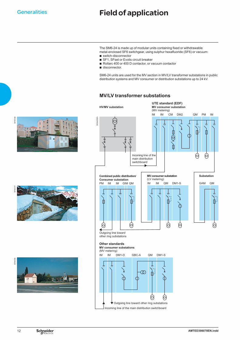
The SM6-24 is made up of modular units containing fixed or withdrawable metal-enclosed SF6 switchgear, using sulphur hexafluoride (SF6) or vacuum:
switch-disconnectorSF1, SFset or Evolis circuit breakerRollarc 400 or 400 D contactor, or vacuum contactordisconnector.
SM6-24 units are used for the MV section in MV/LV transformer substations in public distribution systems and MV consumer or distribution substations up to 24 kV.
bbbb
MV/LV transformer substationsD
E58
400E
N
MT5
5146
MT5
5147
MT5
5148
Generalities Field of application
13AMTED398078EN.indd
QM QM
NSM-busbarsGBM SM TMQM NSM-cablesQM CRM CRM DM1-W
Distribution switchboard
DM1-A DM1-S
DM1-S DM1-SGBC-B
GBC-B
GBC-B
GBC-BQM QMQM IM
IM IMIMB
IM IMB GBM
GBM
DM1-A
Incoming line
ATS
ATS
MV/LV transformer substations
Distribution switchboard
HV/MV substation
Standby generator source
Standby source
Incoming line
Incoming line
Incoming line
Industrial distribution substations
6100
4N
DE
5920
0EN
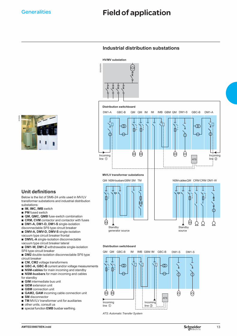
Unit definitionsBelow is the list of SM6-24 units used in MV/LV transformer substations and industrial distribution substations:
IM, IMC, IMB switchPM fused switchQM, QMC, QMB fuse-switch combinationCRM, CVM contactor and contactor with fusesDM1-A, DM1-D, DM1-S single-isolation
disconnectable SF6 type circuit breakerDMV-A, DMV-D, DMV-S single-isolation
vacuum type circuit breaker frontalDMVL-A single-isolation disconnectable
vacuum type circuit breaker lateralDM1-W, DM1-Z withdrawable single-isolation
SF6 type circuit breakerDM2 double-isolation disconnectable SF6 type
circuit breakerCM, CM2 voltage transformersGBC-A, GBC-B current and/or voltage measurementsNSM-cables for main incoming and standbyNSM-busbars for main incoming and cables
for standbyGIM intermediate bus unitGEM extension unitGBM connection unitGAM2, GAM incoming cable connection unitSM disconnectorTM MV/LV transformer unit for auxiliariesother units, consult usspecial function EMB busbar earthing.
bbbbb
b
b
b
b
bbbb
bbbbbbbb
Generalities Field of application
ATS: Automatic Transfer System
14 AMTED398078EN.indd
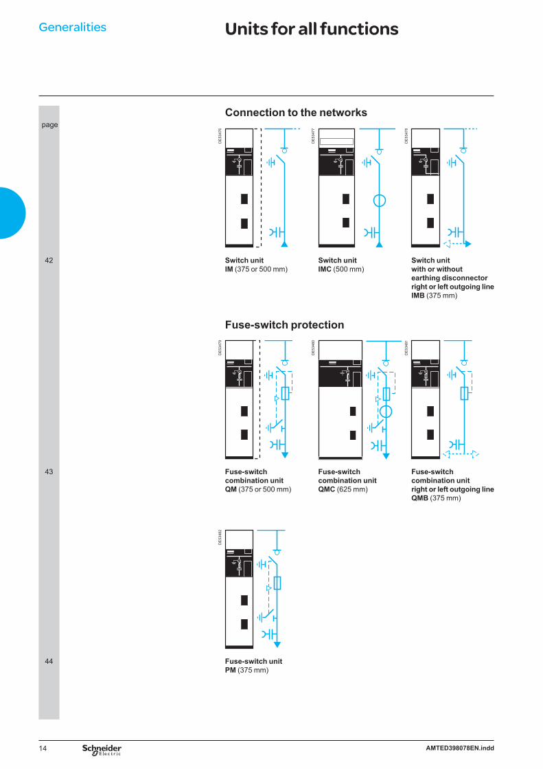
Generalities Units for all functions
Connection to the networks page
DE
5347
6
DE
5347
7
DE
5347
8
42 Switch unit IM (375 or 500 mm)
Switch unit IMC (500 mm)
Switch unit with or withoutearthing disconnectorright or left outgoing lineIMB (375 mm)
Fuse-switch protection
DE
5347
9
DE
5348
0
DE
5348
1
43 Fuse-switch combination unitQM (375 or 500 mm)
Fuse-switch combination unitQMC (625 mm)
Fuse-switch combination unitright or left outgoing line QMB (375 mm)
DE
5348
2
44 Fuse-switch unitPM (375 mm)
15AMTED398078EN.indd
Generalities Units for all functions
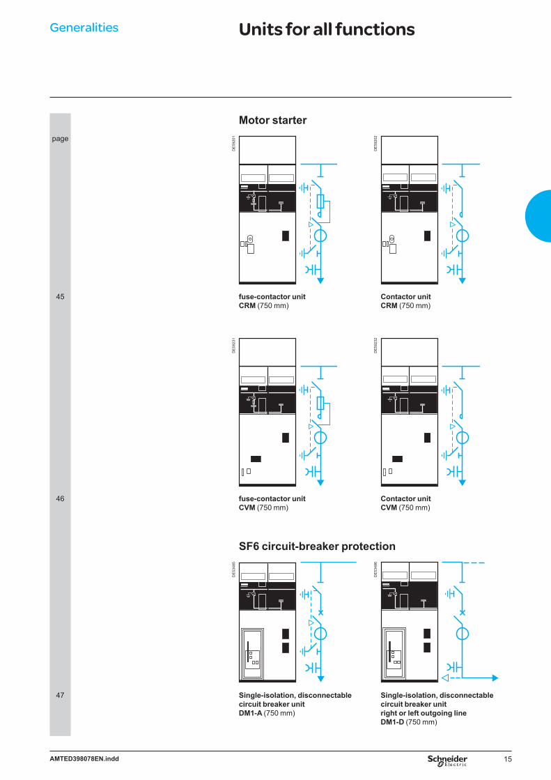
Motor starterpage
DE
5920
1
DE
5920
2
45 fuse-contactor unitCRM (750 mm)
Contactor unitCRM (750 mm)
DE
5923
1
DE
5923
2
46 fuse-contactor unitCVM (750 mm)
Contactor unitCVM (750 mm)
SF6 circuit-breaker protection
DE
5348
5
DE
5348
6
47 Single-isolation, disconnectablecircuit breaker unitDM1-A (750 mm)
Single-isolation, disconnectablecircuit breaker unitright or left outgoing line DM1-D (750 mm)

16 AMTED398078EN.indd
Generalities Units for all functions
SF6 circuit-breaker protectionpage
DE
5348
7
DE
5348
8
48 Single-isolation, disconnectablecircuit breaker unit withautonomous protectionDM1-S (750 mm)
Double-isolation, disconnectablecircuit breaker unitright or left outgoing line DM2 (750 mm)
DE
5348
9
DE
5349
0
49 Withdrawable single-isolationcircuit breaker unitDM1-W (750 mm)
Withdrawable single-isolation circuit breaker unitright outgoing line DM1-Z (750 mm)
Vacuum circuit-breaker protection
DE
5349
1
DE
5349
2
50 Single-isolation circuit breaker unitDMV-A (625 mm)
Single-isolation circuit breaker unitright outgoing line DMV-D (625 mm)

17AMTED398078EN.indd
Generalities Units for all functions
Vacuum circuit-breaker protectionpage
DE
5349
3
DE
5348
5
50 Single-isolation circuit breaker unit withautonomous protectionDMV-S (625 mm)
Single-isolation, disconnectablecircuit breaker unitDMVL-A (750 mm)
MV metering
DE
5349
4
DE
5349
5
51 Voltage transformers for mainswith earthed neutral systemCM (375 mm)
Voltage transformers for mainswith insulated neutral systemCM2 (500 mm)
DE
5349
6
DE
5349
7
52 Current and/or voltagemeasurement unitright or left outgoing line GBC-A (750 mm)
Current and/or voltagemeasurement unitGBC-B (750 mm)

18 AMTED398078EN.indd
Generalities Units for all functions
Casingspage
DE
5349
8
DE
5349
8
DE
5349
9
53 Intermediate bus unit GIM (125 mm)
Extension unit VM6/SM6GEM (125 mm)
Connection unit right or left outgoing lineGBM (375 mm)
DE
5350
0
DE
5350
1
54 Incomingcable-connection unit GAM2 (375 mm)
Incomingcable-connection unitwith earthingGAM (500 mm)

19AMTED398078EN.indd
Generalities Units for all functions
Other functionspage
DE
5350
2
DE
5350
3
DE
5350
4
55 Disconnector unit SM (375 or 500 mm)
MV/LV transformer unitfor auxiliariesTM (375 mm)
Busbar earthing compartment EMB (375 mm)
DE
5350
5
DE
5350
6
56 Cables power supplyfor main incoming lineand standby line NSM-cables (750 mm)
Busbars power supplyfor main incoming line on right or left and cablesfor standby lineNSM-busbars (750 mm)
20 AMTED398078EN.indd
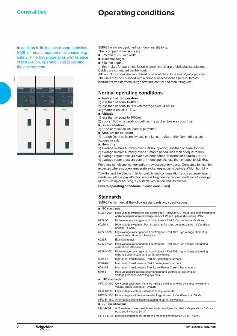
In addition to its technical characteristics, SM6-24 meets requirements concerning safety of life and property as well as ease of installation, operation and protecting the environment.
PE
5715
2
SM6-24 units are designed for indoor installations. Their compact dimensions are:
375 mm to 750 mm width1600 mm height840 mm depth…
… this makes for easy installation in small rooms or prefabricated substations.Cables are connected via the front.All control functions are centralised on a front plate, thus simplifying operation. The units may be equipped with a number of accessories (relays, toroids, instrument transformers, surge arrester, control and monitoring, etc.).
Normal operating conditionsAmbient air temperature:
1) less than or equal to 40°C2) less than or equal to 35°C on average over 24 hours3) greater or equal to –5°C.
Altitude1) less than or equal to 1000 m2) above 1000 m, a derating coefficient is applied (please consult us).
Solar radiation1) no solar radiation influence is permitted.
Ambient air pollution1) no significant pollution by dust, smoke, corrosive and/or flammable gases, vapours or salt.
Humidity1) average relative humidity over a 24 hour period, less than or equal to 95%2) average relative humidity over a 1 month period, less than or equal to 90%3) average vapor pressure over a 24 hour period, less than or equal to 2.2 kPa4) average vapor pressure over a 1 month period, less than or equal to 1.8 kPa.For these conditions, condensation may occasionally occur. Condensation can be expected where sudden temperature changes occur in periods of high humidity.To withstand the effects of high humidity and condensation, such as breakdown of insulation, please pay attention on Civil Engineering recommendations for design of the building or housing, by suitable ventilation and installation.Severe operating conditions (please consult us).
StandardsSM6-24 units meet all the following standards and specifications:
IEC standardsb
62271-200 High-voltage switchgear and controlgear - Part 200: A.C. metal-enclosed switchgear and controlgear for rated voltage above 1 kV and up to and including 52 kV.
62271-1 High-voltage switchgear and controlgear - Part 1: Common specifications.60265-1 High voltage switches - Part 1: switches for rated voltages above 1 kV and less
or equal to 52 kV.62271-105 High-voltage switchgear and controlgear - Part 105: High voltage alternating
current switch-fuse combinations.60255 Electrical relays.62271-100 High-voltage switchgear and controlgear - Part 100: High-voltage alternating
current circuit breakers.62271-102 High-voltage switchgear and controlgear - Part 102: High-voltage alternating
current disconnectors and earthing switches.60044-1 Instrument transformers - Part 1: Current transformers.60044-2 Instrument transformers - Part 2: Voltage transformers.60044-8 Instrument transformers - Part 8: Low Power Current Transducers.61958 High-voltage prefabricated switchgear and controlgear assemblies -
Voltage presence indicating systems. UTE standards b
NFC 13.100 Consumer substation installed inside a building and fed by a second category voltage public distribution system.
NFC 13.200 High voltage electrical installations requirements.NFC 64.130 High voltage switches for rated voltage above 1 kV and less than 52 kV.NFC 64.160. Alternating current disconnectors and earthing switches
EDF specifications b
HN 64-S-41 A.C. metal-enclosed swichgear and controlgear for rated voltages above 1 kV and up to and including 24 kV.
HN 64-S-43 Electrical independent-operating mechanism for switch 24 kV - 400 A.
bbb
b
b
b
b
b
Generalities Operating conditions

21AMTED398078EN.indd
The hereunder values are for working temperatures from -5°C up to +40°C and for a setting up at an altitude below 1000 m.
Internal arc withstand: standard: 12.5 kA 1 s, IAC: A-FLenhanced: 16 kA 1 s, IAC: A-FLR & IAC: A-FL
in accordance with IEC 62271-200.
Protection index: classes: PI (insulating partition)loss of service continuity classes: LSC2Aunits in switchboard: IP3X between compartments: IP2XCubicle: IK08
Electro-magnetic compatibility:relays: 4 kV withstand capacity,
as per recommendation IEC 60801.4compartments:electrical field: 40 dB attenuation at 100 MHz20 dB attenuation at 200 MHzmagnetic field: 20 dB attenuation below 30 MHz.
Temperatures:The cubicles must be stored and installed in a dry area free from dust and with limited temperature variations.
for stocking: from – 40°C to +70°C,for working: from – 5°C to +40°C,other temperatures, consult us.
bb
bbbbb
b
bv--v
bbb
Generalities Main characteristicsP
E57
150
Electrical characteristicsRated voltage Ur kV 7.2 12 17.5 24Insulation level
Insulation Ud 50/60 Hz, 1 min (kV rms) 20 28 38 50Isolation Ud 50/60 Hz, 1 min (kV rms) 23 32 45 60Insulation Up 1.2/50 µs (kV peak) 60 75 (1) 95 125Isolation Up 1.2/50 µs (kV peak) 70 85 110 145Breaking capacity
Transformer off load A 16Cables off load A 31.5Rated current Ir A 400 - 630 -1250Short-time withstandcurrent
Ik/tk (4) kA /1 s 25 630 - 125020 630 - 125016 630 - 125012.5 400 - 630 - 1250
Making capacity Ima kA 62.5 630 NA50 630 40 630 31.25 400 - 630
Maximum breaking capacity (Isc)Units IM, IMC, IMB, NSM-cables, NSM-busbars
A 630 - 800 (2)
QM, QMC, QMB kA 25 20PM kA 25CRM kA 10 8 NACRM with fuses kA 25 NACVM kA 6.3 NACVM with fuses kA 25 NASF6 circuit breaker range
DM1-A, DM1-D, DM1-W,DM1-Z, DM1-S, DM2
kA 25
Vacuum circuit breaker rangeDMV-A, DMV-D, DMV-S kA 25 NADMVL-A kA 20
EnduranceUnits Mechanical endurance Electrical endurance
Units IM, IMC, IMB, PM,QM (3), QMC (3), QMB (3),NSM-cables, NSM-busbars
IEC 602651 000 operationsclass M1
IEC 60265-1100 breaks at Ir, p.f. = 0.7, class E3
CRM Disconnector IEC 62271-1021 000 operations
Rollarc 400 IEC 60470300 000 operations
IEC 60470100 000 breaks at 320 A300 000 breaks at 250 A
Rollarc 400D 100 000 operations 100 000 breaks at 200 ACVM Disconnector IEC 62271-102
1 000 operationsVacuum contactor IEC 60470
2 500 000 operations250 000 with mechanical latching
IEC 60470 250 000 breaks at Ir
SF6 circuit breaker rangeDM1-A, DM1-D, DM1-W,DM1-Z, DM1-S, DM2
Disconnector IEC 62271-1021 000 operations
SF circuit breaker IEC 62271-10010 000 operationsclass M2
IEC 62271-10040 breaks at 12.5 kA25 breaks at 25 kA10 000 breaks at Ir, p.f. = 0.7, class E2
Vacuum circuit breaker rangeDMV-A,DMV-D,DMV-S
Switch IEC 602651 000 operationsclass M1
IEC 60265100 breaks at Ir, p.f. = 0.7, class E3
Evolis circuit breaker
IEC 62271-10010 000 operationsclass M2
IEC 62271-10010 000 breaks at Ir, p.f. = 0.7, class E2
DMVL-A Disconnector IEC 62271-1021 000 operations
Evolis circuit breaker
IEC 62271-10010 000 operationsclass M2
IEC 62271-10010 000 breaks at Ir, p.f. = 0.7, class E2
NA: Non Available (1) 60 kV peak for the CRM unit (2) In 800 A, consult us(3) As per recommendation IEC 62271-105, three breakings at p.f. = 0.2(4) 3 phases
b 1730 A under 12 kV b 1400 A under 24 kV
22 AMTED398078EN.indd
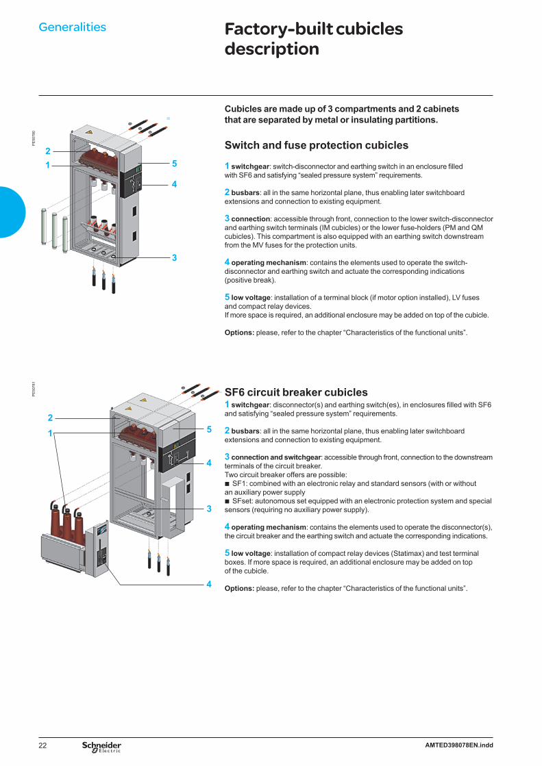
Cubicles are made up of 3 compartments and 2 cabinets that are separated by metal or insulating partitions.
Switch and fuse protection cubicles
1 switchgear: switch-disconnector and earthing switch in an enclosure filled with SF6 and satisfying “sealed pressure system” requirements.
2 busbars: all in the same horizontal plane, thus enabling later switchboard extensions and connection to existing equipment.
3 connection: accessible through front, connection to the lower switch-disconnector and earthing switch terminals (IM cubicles) or the lower fuse-holders (PM and QM cubicles). This compartment is also equipped with an earthing switch downstream from the MV fuses for the protection units.
4 operating mechanism: contains the elements used to operate the switch-disconnector and earthing switch and actuate the corresponding indications (positive break).
5 low voltage: installation of a terminal block (if motor option installed), LV fuses and compact relay devices.If more space is required, an additional enclosure may be added on top of the cubicle.
Options: please, refer to the chapter “Characteristics of the functional units”.
SF6 circuit breaker cubicles1 switchgear: disconnector(s) and earthing switch(es), in enclosures filled with SF6 and satisfying “sealed pressure system” requirements.
2 busbars: all in the same horizontal plane, thus enabling later switchboard extensions and connection to existing equipment.
3 connection and switchgear: accessible through front, connection to the downstream terminals of the circuit breaker.Two circuit breaker offers are possible:
SF1: combined with an electronic relay and standard sensors (with or without an auxiliary power supply
SFset: autonomous set equipped with an electronic protection system and special sensors (requiring no auxiliary power supply).
4 operating mechanism: contains the elements used to operate the disconnector(s), the circuit breaker and the earthing switch and actuate the corresponding indications.
5 low voltage: installation of compact relay devices (Statimax) and test terminal boxes. If more space is required, an additional enclosure may be added on top of the cubicle.
Options: please, refer to the chapter “Characteristics of the functional units”.
b
b
PE
5078
0
21 5
4
3
PE
5078
1
21 5
4
3
4
Generalities Factory-built cubicles description
23AMTED398078EN.indd
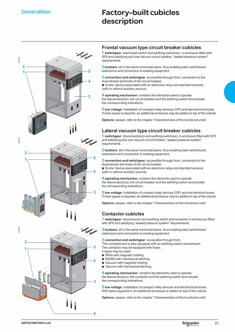
Frontal vacuum type circuit breaker cubicles1 switchgear: load break switch and earthing switch(es), in enclosure filled with SF6 and satisfying and one vacuum circuit breaker, “sealed pressure system” requirements.
2 busbars: all in the same horizontal plane, thus enabling later switchboard extensions and connection to existing equipment.
3 connection and switchgear: accessible through front, connection to the downstream terminals of the circuit breaker.
Evolis: device associated with an electronic relay and standard sensors (with or without auxiliary source).
4 operating mechanism: contains the elements used to operate the disconnector(s), the circuit breaker and the earthing switch and actuate the corresponding indications.
5 low voltage: installation of compact relay devices (VIP) and test terminal boxes. If more space is required, an additional enclosure may be added on top of the cubicle.
Options: please, refer to the chapter “Characteristics of the functional units”.
Lateral vacuum type circuit breaker cubicles1 switchgear: disconnector(s) and earthing switch(es), in enclosure filled with SF6 and satisfying and one vacuum circuit breaker, “sealed pressure system” requirements.
2 busbars: all in the same horizontal plane, thus enabling later switchboard extensions and connection to existing equipment.
3 connection and switchgear: accessible through front, connection to the downstream terminals of the circuit breaker.
Evolis: device associated with an electronic relay and standard sensors (with or without auxiliary source).
4 operating mechanism: contains the elements used to operate the disconnector(s), the circuit breaker and the earthing switch and actuate the corresponding indications.
5 low voltage: installation of compact relay devices (VIP) and test terminal boxes. If more space is required, an additional enclosure may be added on top of the cubicle.
Options: please, refer to the chapter “Characteristics of the functional units”.
Contactor cubicles1 switchgear: disconnector and earthing switch and contactor in enclosures filled with SF6 and satisfying “sealed pressure system” requirements.
2 busbars: all in the same horizontal plane, thus enabling later switchboard extensions and connection to existing equipment.
3 connection and switchgear: accessible through front.This compartment is also equipped with an earthing switch downstream.The contactor may be equipped with fuses.4 types may be used:
R400 with magnetic holdingR400D with mechanical latchingVacuum with magnetic holdingVacuum with mechanical latching.
4 operating mechanism: contains the elements used to operate the disconnector(s), the contactor and the earthing switch and actuate the corresponding indications.
5 low voltage: installation of compact relay devices and test terminal boxes.With basic equipment, an additional enclosure is added on top of the cubicle.
Options: please, refer to the chapter “Characteristics of the functional units”.
b
b
bbbb
PE
5078
2
21 5
4
3
PE
5078
4P
E50
783
21 5
4
3
21 5
4
3
4
Generalities Factory-built cubicles description

24 AMTED398078EN.indd
Generalities Compartments descriptionD
E53
507
6100
7N Busbar compartmentThe three insulated busbars are parallel-mounted. Connection is made to the upper pads of the enclosure using a field distributor with integrated captive screws.Ratings 400 - 630 - 1250 A.
DE
5350
8
6100
6N Switch compartmentThis compartment is separated from the busbar compartment and the connection compartment by the enclosure surrounding the switch, the disconnector and the earthing switch.
DE
5350
9 Connection and switch compartmentThe network cables are connected:
to the terminals of the switch to the lower fuse holders or to the connection pads of the circuit breaker.
Cables may have either:cold fitted cable end for dry-type
With basic equipment, the maximum allowable cross-section for cable is: 630 mm2 or 2 x 400 mm2 for 1250 A incoming or outgoing units 240 mm2 or 2 x 240 mm2 for incoming or outgoing units 400 - 630 A95 mm2 for transformer protection cubicles incorporating fuses.
See in fonctional units characteristics chapter for each unit allowable section.The earthing switch must be closed before the cubicle may be accessed.The reduced depth of the cubicle makes for easy connection of all phases.A stud incorporated in the field distributor makes it possible to position and secure the cable-end lug with a single hand.
bbb
b
bbb
SF6 and vacuum lateral type circuit breaker
DE
5351
0
Frontal vacuum type circuit breaker
25AMTED398078EN.indd
Generalities Compartments descriptionD
E53
511
6100
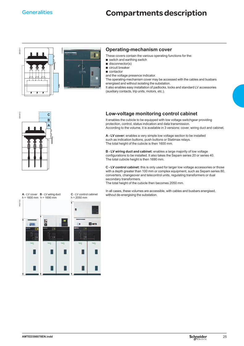
8N Operating-mechanism coverThese covers contain the various operating functions for the:
switch and earthing switchdisconnector(s)circuit breakercontactor
and the voltage presence indicator.The operating-mechanism cover may be accessed with the cables and busbars energised and without isolating the substation.It also enables easy installation of padlocks, locks and standard LV accessories (auxiliary contacts, trip units, motors, etc.).
bbbb
DE
5351
2
C
B
A
Low-voltage monitoring control cabinetIt enables the cubicle to be equipped with low voltage switchgear providing protection, control, status indication and data transmission. According to the volume, it is available in 3 versions: cover, wiring duct and cabinet.
A - LV cover: enables a very simple low voltage section to be installed such as indication buttons, push buttons or Statimax relays.The total height of the cubicle is then 1600 mm.
B - LV wiring duct and cabinet: enables a large majority of low voltage configurations to be installed. It also takes the Sepam series 20 or series 40. The total cubicle height is then 1690 mm.
C - LV control cabinet: this is only used for larger low voltage accessories or those with a depth greater than 100 mm or complex equipment, such as Sepam series 80, converters, changeover and telecontrol units, regulating transformers or dual secondary transformers. The total height of the cubicle then becomes 2050 mm.
In all cases, these volumes are accessible, with cables and busbars energised, without de-energising the substation. A - LV cover B - LV wiring duct
h = 1600 mm h = 1690 mmC - LV control cabineth = 2050 mm
PE
5715
3
26 AMTED398078EN.indd
Generalities Safety of peopleBy switchgear
6101
0N61
011N
Switch-disconnector
Rollarc contactor
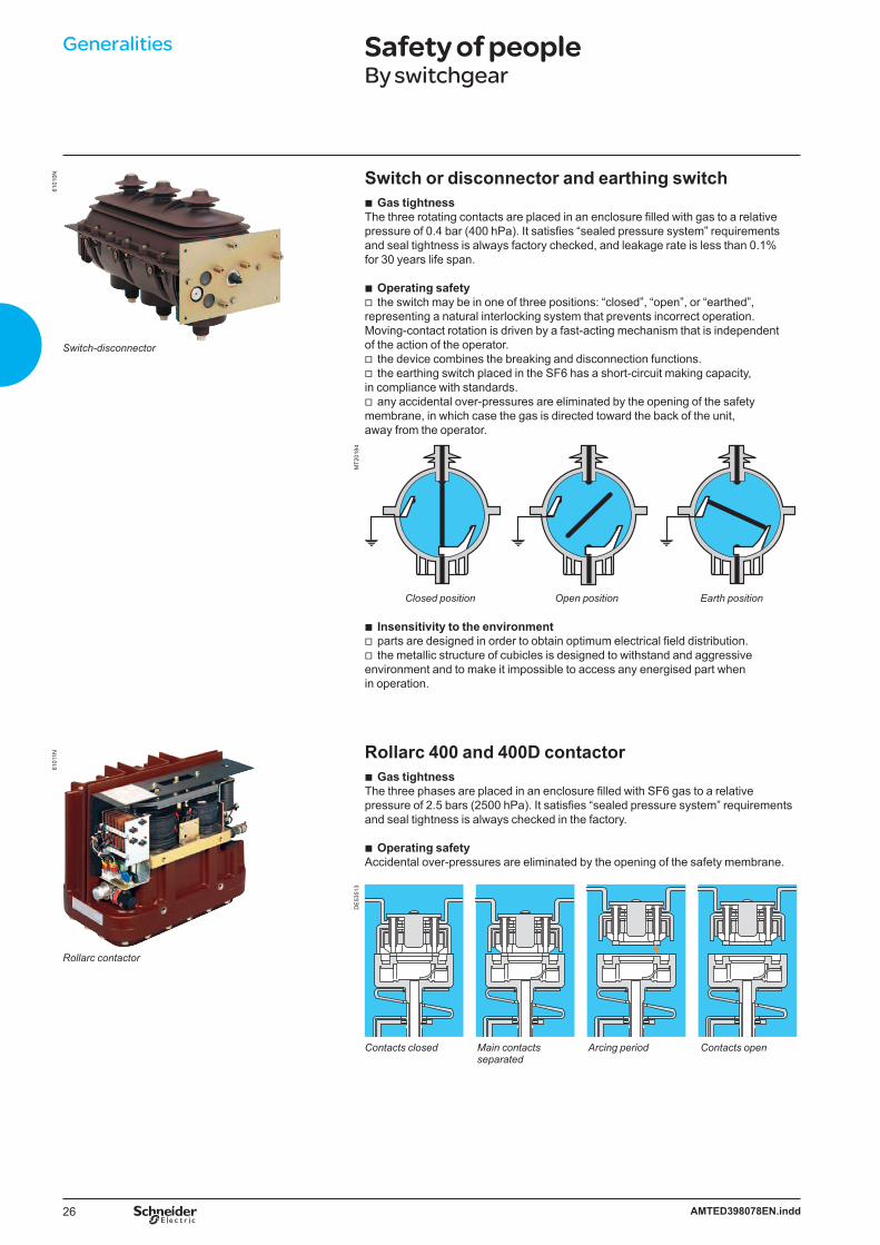
Switch or disconnector and earthing switchGas tightness
The three rotating contacts are placed in an enclosure filled with gas to a relative pressure of 0.4 bar (400 hPa). It satisfies “sealed pressure system” requirements and seal tightness is always factory checked, and leakage rate is less than 0.1% for 30 years life span.
Operating safetythe switch may be in one of three positions: “closed”, “open”, or “earthed”,
representing a natural interlocking system that prevents incorrect operation.Moving-contact rotation is driven by a fast-acting mechanism that is independent of the action of the operator.
the device combines the breaking and disconnection functions.the earthing switch placed in the SF6 has a short-circuit making capacity,
in compliance with standards.any accidental over-pressures are eliminated by the opening of the safety
membrane, in which case the gas is directed toward the back of the unit, away from the operator.
b
bv
vv
v
MT2
0184
Closed position Open position Earth position
Insensitivity to the environmentparts are designed in order to obtain optimum electrical field distribution.the metallic structure of cubicles is designed to withstand and aggressive
environment and to make it impossible to access any energised part when in operation.
Rollarc 400 and 400D contactorGas tightness
The three phases are placed in an enclosure filled with SF6 gas to a relative pressure of 2.5 bars (2500 hPa). It satisfies “sealed pressure system” requirements and seal tightness is always checked in the factory.
Operating safetyAccidental over-pressures are eliminated by the opening of the safety membrane.
bvv
b
b
DE
5351
3
Contacts closed Main contacts Arcing period Contacts open separated
27AMTED398078EN.indd
6101
2N
SF1 circuit breaker
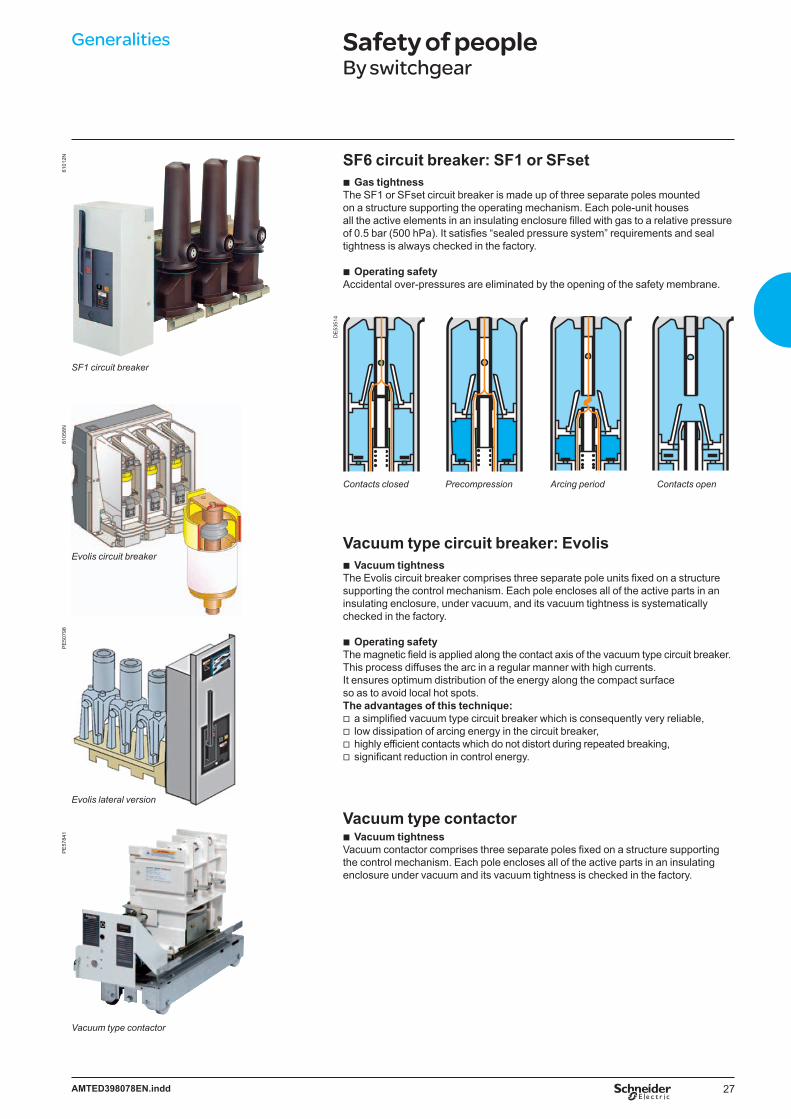
SF6 circuit breaker: SF1 or SFsetGas tightness
The SF1 or SFset circuit breaker is made up of three separate poles mounted on a structure supporting the operating mechanism. Each pole-unit houses all the active elements in an insulating enclosure filled with gas to a relative pressure of 0.5 bar (500 hPa). It satisfies “sealed pressure system” requirements and seal tightness is always checked in the factory.
Operating safetyAccidental over-pressures are eliminated by the opening of the safety membrane.
b
b
DE
5351
4
Vacuum type circuit breaker: EvolisVacuum tightness
The Evolis circuit breaker comprises three separate pole units fixed on a structure supporting the control mechanism. Each pole encloses all of the active parts in an insulating enclosure, under vacuum, and its vacuum tightness is systematically checked in the factory.
Operating safetyThe magnetic field is applied along the contact axis of the vacuum type circuit breaker.This process diffuses the arc in a regular manner with high currents. It ensures optimum distribution of the energy along the compact surface so as to avoid local hot spots.The advantages of this technique:
a simplified vacuum type circuit breaker which is consequently very reliable,low dissipation of arcing energy in the circuit breaker,highly efficient contacts which do not distort during repeated breaking,significant reduction in control energy.
Vacuum type contactorVacuum tightness
Vacuum contactor comprises three separate poles fixed on a structure supporting the control mechanism. Each pole encloses all of the active parts in an insulating enclosure under vacuum and its vacuum tightness is checked in the factory.
b
b
vvvv
b
Contacts closed Precompression Arcing period Contacts open
6105
8N
Evolis circuit breaker
PE
5079
8
Generalities Safety of peopleBy switchgear
Evolis lateral version
PE
5784
1
Vacuum type contactor
28 AMTED398078EN.indd
Generalities Safety of peopleBy operating mechanism safety
Reliable operating mechanismSwitchgear status indicator:
Fitted directly to the drive shaft, these give a definite indication of the contact’s position. (appendix A of standard IEC 62271-102).
Operating lever: This is designed with an anti-reflex device that stops any attempt to re-open the device immediately after closing the switch or the earthing disconnector.
Locking device: Between one and three padlocks enable the following to be locked:v access to the switching shaft of the switch or the circuit breaker,v access to the switching shaft of the earthing disconnector,v operating of the opening release push-button.
Simple and effortless switchingMechanical and electrical controls are side by side on the front fascia, on a panel including the schematic diagram indicating the device’s status (closed, open, earthed):
Closed: the drive shaft is operated via a quick acting mechanism, independent of the operator. No energy is stored in the switch, apart from when switching operations are taking place.For combined switch fuses, the opening mechanism is armed at the same time as the contacts are closed.
Opening: the switch is opened using the same quick acting mechanism, operated in the opposite direction.For circuit breakers and the combined switch fuses, opening is controlled by:
a push-button,a fault.Earthing: a specific control shaft enables the opening or closing of the earthing
contacts. Access to this shaft is blocked by a cover that can be slid back if the switch is open but which remains locked in place if it is closed.
Visibility of main contacts (option)The position of main contacts is clearly visible from the front of the cubicle through the window.
Gas pressure indicator (option) Despite SM6 switch is sealed pressure system and has open and close capacity on rated current at 0 bar relative pressure SF6, to insure you about the internal pressure, we propose on request before sale or on site by after-sales either a pressure switch or an analog manometer on the switch. These devices are both fitted without any alteration on the switch, they are temperature compensated and compatible with visibility of main contacts if requested.
Voltage presence indicatorThis device has integrated VPIS (Voltage Presence Indicating System) type lights, in conformity with IEC standard 61958, enabling the presence (or absence) of voltage to be checked on the cables.
b
b
b
b
b
vvb
6101
3NP
E50
796
PE
5682
3P
E57
166
Visibility of main contacts (option)
29AMTED398078EN.indd
Generalities Safety of peopleBy internal arc protection
Standard IEC 62271-200 appendix A indicates a method for testing switchgear in metal enclosures under internal arc conditions. The aim of this test is to show that an operator situated in front of a switchboard would be protected against the effects of an internal fault.
DE
5555
3
To enhance the safety of people, it is desirable to provide as high a degree of protection as possible by evacuating the effects of internal arc using:
evacuation systems which direct gases towards the top or the bottom of the switchboard enabling over pressure to be limited in the case of an internal fault in the compartments
channelling and evacuating hot gases towards an external area, which is not hazardous for the operator
materials which are non-inflammable in the cubiclesreinforced panels.
Consequently: The SM6-24 is designed to offer a good level of safety
Control of the architecture:compartment type enclosure.Technological control:electrotechnical: modelling of electrical fields,mechanical: parts produced using CAD systems.Use of reliable components: choice of materials, earthing switch with closing capacity.Devices for total operating safety:voltage presence indicator on the front face,natural reliable interlocking,locking using keys or padlocks.
Internal arc withstand of the cubicles2 versions are available:basic version: 12.5 kA 1 s, IAC: A-FLenhanced internal arc withstand: 16 kA 1 s, IAC: A-FL or IAC: A-FLR.
SM6-24 internal arc (in conformity with IEC 62271-200 appendix A)In its internal arc version, the SM6-24 has successfully passed all of the type testing relative to standard IEC 62271-200 (5 acceptance criteria).The materials used meet the constraints for which the SM6-24 is designed. The thermal and mechanical forces that an internal arc can produce are perfectly absorbed by the enclosure.An operator situated in the front of the SM6-24 switchboard during an internal fault will not be exposed to the effects of arcing.
SM6-24 proposes several options to install an internal arc enhanced switchboard
3-sides internal arc protection IAC: A-FL, 12,5 kA 1 s, 16 kA 1 sSM6-24 switchboard positioned against the wall, access to the rear of the cubicles is impossible, internal arc protection on three sides is sufficient.
4-sides internal arc protection IAC: A-FLR, 16 kA 1 sFor SM6-24 switchboards installed in the middle of a room, 4-sides internal arc protection is necessary in order to protect an operator moving around the switchboard.
Choice of exhaustThe choice depends on the civil engineering:
Upwards exhaust: A ceiling height greater or equal than 2 800 mm is necessary.
Downwards exhaust:Civil engineering with an adequate volume is necessary.
b
b
bb
bvbvvbvvbvvv
bvv
b
b
b
b
Installation of an SM6-24 switchboard installed against the wall downwards exhaust 12.5 kA 1 s and 16 kA 1 s: 3-sides internal arc protection
Installation of an SM6-24 switchboard installed in the middle of a room upwards exhaust 16 kA 1 s: 4-sides internal arc protection
DE
5351
5
Installation of an SM6-24 switchboard installed in the middle of a room downwards exhaust 16 kA 1 s: 4-sides internal arc protection
DE
5351
6
30 AMTED398078EN.indd
Generalities MV electrical network management
PE
1507
4
Easergy T200 S: remote control interface in LV control cabinet
Easergy T200 S is a simplified MV substation control unit for secondary distribution networks enabling remote control of one or two MV substation switches.T200 S, a version of the T200 I unit, is integrated in the SM6-24 cubicle LV control cabinet. It is limited to control 2 switches. It is intended for remote control applications for source transfer switching and back up generator set switching in NSM cubicle.
Easergy T200 S a multifunctional “plug and play” interface which integrates all functions required for remote monitoring and control of MV substations:
acquisition of various data types: switch position, fault detectors, current values, etc.transmission of opening and closing orders to the switchesexchange with the control center.
Particularly used during network incidents, Easergy T200 S has proven its reliability and availability to be able to operate the switchgear at all times. It is easy to implement and operate.
Functional unit dedicated to Medium Voltage applicationsEasergy T200 S is installed in the low voltage control cabinet of IM and NSM cubicles for remote control of one or two switches.Easergy notably enables source transfer switching between two switches.It has a simple panel for local operation to manage electrical controls (local/remote switch) and to display switchgear status information.It integrates a fault current detector (overcurrent and zero sequence current) with detection thresholds configurable channel by channel (threshold and fault duration).
“Plug and play” and secureIntegrated in the low voltage control cabinet of an MV-equipped cubicle, it is ready to connect to the data transmission system.Easergy T200 S has been subject to severe tests on its resistance to MV electrical constraints. A back-up power supply guarantees several hours continuity of service for the electronic devices, motorization and MV switchgear.Current transformers are of split core type for easier installation.
Compatible with all SCADA remote control systemsEasergy T200 S supplies the following standard protocols:Modbus, DPN3.0 level 2 and IEC 870-5-101.Data transmission system standards are: RS232, RS485, PSTN, FSK.Other systems are available on request, the radio frequency emitter/receiver is not supplied.
bbb
6101
7N
6101
9N
6102
0N
PE
1500
78
PE
1500
79
Control command Local information Power unit Split core CTs Back up power supply

31AMTED398078EN.indd
PE
5631
1 Easergy T200 I: an interface designedfor telecontrol of MV networksEasergy T200 I is a “plug and play” or multifunction interface that integrates all the functional units necessary for remote supervision and control of the SM6-24:
acquisition of the different types of information: switch position, fault detectors, current values...
transmission of switch open/close ordersexchanges with the control center.
Required particularly during outages in the network, Easergy T200 I is of proven reliability and availability, being able to ensure switchgear operation at any moment.It is simple to set up and to operate.
Functional unit designed for the Medium Voltage networkEasergy T200 I is designed to be connected directly to the MV switchgear,
without requiring a special converter.It has a simple front plate for local operation, which allows management of
electrical rating mechanisms (local/remote switch) and display of information concerning switchgear status.
It has an integrated MV network fault current detection system (overcurrent and zero sequence) with detection set points that can be configured channel by channel (current value and fault current duration).
Medium Voltage switchgear operating guaranteeEasergy T200 I has undergone severe MV electrical stress withstand tests.It is a backed up power supply which guarantees continuity of service for several
hours in case of loss of the auxiliary source, and supplies power to the Easergy T200 I and the MV switchgear motor mechanisms.
Ready to plugEasergy T200 I is delivered with a kit that makes it easy to connect the motor
mechanisms and collect measurements.the telecontrol cabinet connectors are polarized to avoid any errors during
installation or maintenance interventions.current measurement acquisition sensors are of the split type, to facilitate
their installation.works with 24 Vdc and 48 Vdc motor units.
b
bb
b
b
b
bb
bv
v
v
v
Local information and control Monitoring and control
Back up power supply Polarized connectors
PE
5642
1
PE
5642
2
PE
5642
3
Generalities MV electrical network management
PE
5682
4

32 AMTED398078EN.indd
Generalities Fault indicators
Easergy Flair is a comprehensive range of underground network fault current indicators
Easergy MV underground network fault current passage indicators are a range of products adapted to all neutral earthing systems: insulated, impedant and direct earthing.
Easergy Flair 21D-22DV-23DV, are self-powered with a liquid crystal display, with DIN dimensions for MV cubicle installation.
Easergy Flair 279 and 219, have a wall-mounted case for the MV cubicles substation or LV compartment and anexternal power supply which can be backed up.
Easergy Flair 200C (communicative), has the same case as Flair 279 and 219, but has advanced measurement functions and long distance communication features (radio, GSM, RTC, etc.).
PE
5715
4
PE
5792
2
PE
5792
1
Easergy Flair 21D - 22DV - 23DV 279 - 219 200CUsage Underground MV networks, open loop, insulated,
impedant and direct neutral earthing systems.Installation Flush fitted Casing CasingPower supply Self-powered
or dual power230 Vacor battery
230 Vac
Fault detection Phase-phase and phase-earth for all 3 rangesIndication LCD display Indicator light Indicator light (option)
Measurement Current,frequency
Current, voltage, power
Communication SCADA interfaceby dry contact
SCADA interfaceby dry contact
Long distance (radio, PSTN, GSM, etc.)
Easergy Flair 21D - 22DV - 23DVSM6-24 integrates Flair 21D, Flair 22DV and Flair 23DV on every incoming cubicles.b High performance indicators
indication of phase-phase and phase-earth faults,faulty phase indication,compatible with HV/MV substation protection devices.
b Clear and comprehensive displaydisplaying the faulty phase for earth fault,displaying settings,displaying the load current including peak demand and frequency meter.
b Maintenance free.
Flair 21D Flair 22DV Flair 23DVPower supplySelf-powered b b bDual power supply b (battery) b (external)Display of settingsShort-circuit fault thresholds b b bEarth fault thresholds b b bValidation (no current) b b bReset upon return of current b b bReset timer b bFaulty phase and measurementsFaulty phase L1-L2-L3 L1-L2-L3 L1-L2-L3 Load current b b bMV network frequency 50/60 Hz 50/60 HzPeak demand current b bResidual current b
b
b
b
vvv
vvv
PE
5715
5
33AMTED398078EN.indd
b At the leading edge of technology, Amp 21D is suitable for Medium Voltage network load management.b Self-powered, it ensures a permanent display of currents.b Compact and in DIN format, it fits naturally into MV cubicles.b Cost efficient, it uses the CT optimised for Fault Passage Indicator.b Performant, it displays phase current and maximum of current.
PE
5716
9
Easergy Amp 21D is an ammeter dedicated to display the load current on a Medium Voltage network. It is particularly suited for network load management application.
Functions Display of 3 phase current: I1 , I2 , I3. Range: 3 A to 800 A Display of 3 phase current maximeter: I1 , I2 , I3. Range: 3 to 800 A.
Display principleLoad curents are permanently displayedcontinuous scrolling of L1, then L2, then L3.Maximeteraccess to maximeter display by pressing a dedicated push buttoncontinuous scrolling of M1, then M2, then M3reset of all maximeter by pressing a combination of two push buttons.
AssemblySmall size enclosure
DIN format : 93 x 45 mmSecured, extraction-proof mountingTerminal connections.
Technical dataApplication
Frequency 50 Hz and 60 HzLoad current Minimum current > 3 AMeasurement
Range Phase current 3 to 800 A Accuracy (I < 630 A) ± 5%, ± 2 A
Reset of maximeter Manual from device YesPower supply
Self power From the current sensors I load > 3 ABattery NoAuxiliary supply NoDisplay
Display 4 digits LCDCurrent per phase Yes (resolution 1 A)Maximeter per phase Yes
SensorsPhase CTs 3 split core CT
MiscellaneousTest Yes
CharacteristicsDielectric IEC 60255-5Electromagnetic IEC 61000-4-4 (level 4)
IEC 61000-4-12Insulation 10 kVShock wave 20 kV
Climatic Operating temperature Storage temperatureSalt fog
– 25°C to + 70°C– 40°C to + 85°C200 h
Mechanical IEC 60068-2-6IEC 60068-2-29
Vibrations 10 to 500 Hz: 2 gProtection IP23
bb
bvbvvv
bbb
The SM6-24 integrates ammeter Amp 21D on all incoming cubicles and the fuse-switch cubicles
PE
5682
2D
E58
404
Amp 21D
L1
L2
L3
Generalities Ammeter
34 AMTED398078EN.indd
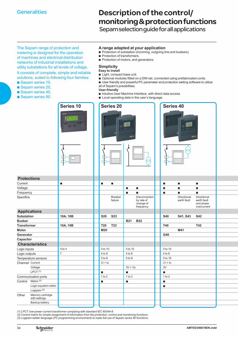
Generalities Description of the control/monitoring & protection functions Sepam selection guide for all applications
The Sepam range of protection and metering is designed for the operation of machines and electrical distribution networks of industrial installations and utility substations for all levels of voltage. It consists of complete, simple and reliable solutions, suited to following four families:b Sepam series 10, b Sepam series 20, b Sepam series 40,b Sepam series 80.
A range adapted at your applicationProtection of substation (incoming, outgoing line and busbars).Protection of transformers. Protection of motors, and generators.
SimplicityEasy to install
Light, compact base unit.Optional modules fitted on a DIN rail, connected using prefabricated cords.User friendly and powerful PC parameter and protection setting software to utilize
all of Sepam’s possibilities.User-friendly
Intuitive User Machine Interface, with direct data access.Local operating data in the user’s language.
bbb
bbb
bb
Series 10 Series 20 Series 40
ProtectionsCurrent b b b b b b
Voltage b b b b b
Frequency b b b b b
Specifics Breaker failure
Disconnection by rate of change of frequency
Directional earth fault
Directional earth fault and phase overcurrent
ApplicationsSubstation 10A, 10B S20 S23 S40 S41, S43 S42Busbar B21 B22Transformer 10A, 10B T20 T23 T40 T42Motor M20 M41Generator G40Capacitor CharacteristicsLogic inputs 0 to 4 0 to 10 0 to 10 0 to 10
Logic outputs 7 4 to 8 4 to 8 4 to 8
Temperature sensors 0 to 8 0 to 8 0 to 16
Channel Current 3 I + Io 3 I + IoVoltage 3V + Vo 3VLPCT (1) b b b
Communication ports 1 to 2 1 to 2 1 to 2
Control Matrix (2) b b bLogic equation editor bLogipam (3)
Other Memory cartridge with settingsBackup battery
(1) LPCT: low-power current transformer complying with standard IEC 60044-8.(2) Control matrix for simple assignment of information from the protection, control and monitoring functions.(3) Logipam ladder language (PC programming environment) to make full use of Sepam series 80 functions.

35AMTED398078EN.indd
Generalities Description of the control/monitoring & protection functions Sepam selection guide for all applications
Series 80
M
b b b b b b b b
b b b b b b b b
b b b b b b b bDirectional earth fault
Directional earth fault and phase overcurrent
Disconnection by rate of change of frequency
Transformer & transformer-machine unit differential
Machine differential
Voltage and frequency protection for 2 sets of busbars
Capacitor-bank unbalance
S80 S81 S82 S84B80 B83
T81 T82 T87M81 M88 M87
G82 G88 G87C86
0 to 42 0 to 42 0 to 42 0 to 425 to 23 5 to 23 5 to 23 5 to 230 to 16 0 to 16 0 to 16 0 to 163 I + 2 x Io 2 x 3 I + 2 x Io 3 I + Io 2 x 3 I + 2 x Io3V + Vo 3V + Vo 2 x 3V + 2 x Vo 3V + Vo
b b b b2 to 4 2 to 4 2 to 4 2 to 4
b b b b
b b b b
b b b b
b b b b
b b b b
Accurate measurement and detailed diagnosisMeasuring all necessary electrical values.Monitoring switchgear status: sensors and trip circuit, mechanical switchgear status.Disturbance recording.Sepam self-diagnosis and watchdog.
Flexibility and evolutivityEnhanced by optional modules to evolve in step with your installation.Possible to add optional modules at any time.Simple to connect and commission via a parameter setting procedure.
bbbb
bbb
36 AMTED398078EN.indd
Generalities Description of the control/monitoring & protection functions
PE
5715
9
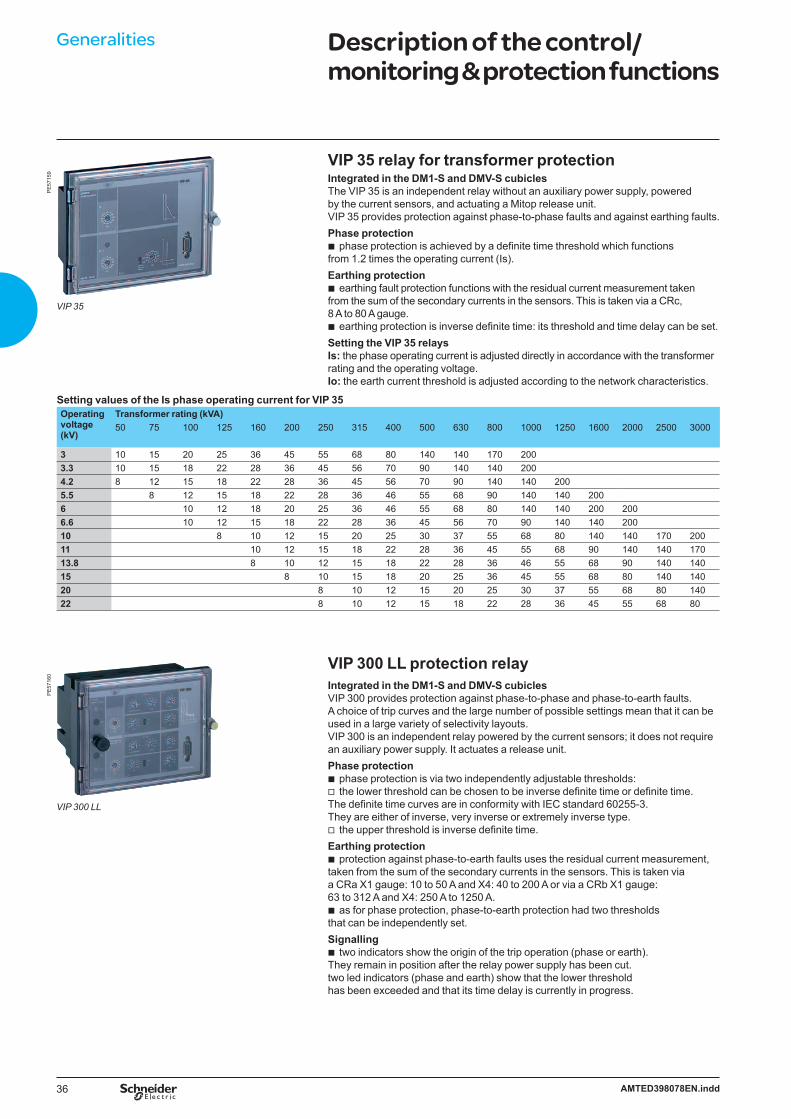
VIP 35
VIP 35 relay for transformer protectionIntegrated in the DM1-S and DMV-S cubiclesThe VIP 35 is an independent relay without an auxiliary power supply, powered by the current sensors, and actuating a Mitop release unit. VIP 35 provides protection against phase-to-phase faults and against earthing faults.Phase protection
phase protection is achieved by a definite time threshold which functions from 1.2 times the operating current (Is). Earthing protection
earthing fault protection functions with the residual current measurement takenfrom the sum of the secondary currents in the sensors. This is taken via a CRc, 8 A to 80 A gauge.
earthing protection is inverse definite time: its threshold and time delay can be set.Setting the VIP 35 relaysIs: the phase operating current is adjusted directly in accordance with the transformer rating and the operating voltage.Io: the earth current threshold is adjusted according to the network characteristics.
Setting values of the Is phase operating current for VIP 35Operating voltage (kV)
Transformer rating (kVA)50 75 100 125 160 200 250 315 400 500 630 800 1000 1250 1600 2000 2500 3000
3 10 15 20 25 36 45 55 68 80 140 140 170 2003.3 10 15 18 22 28 36 45 56 70 90 140 140 2004.2 8 12 15 18 22 28 36 45 56 70 90 140 140 2005.5 8 12 15 18 22 28 36 46 55 68 90 140 140 2006 10 12 18 20 25 36 46 55 68 80 140 140 200 2006.6 10 12 15 18 22 28 36 45 56 70 90 140 140 20010 8 10 12 15 20 25 30 37 55 68 80 140 140 170 20011 10 12 15 18 22 28 36 45 55 68 90 140 140 17013.8 8 10 12 15 18 22 28 36 46 55 68 90 140 14015 8 10 15 18 20 25 36 45 55 68 80 140 14020 8 10 12 15 20 25 30 37 55 68 80 14022 8 10 12 15 18 22 28 36 45 55 68 80
VIP 300 LL protection relayIntegrated in the DM1-S and DMV-S cubiclesVIP 300 provides protection against phase-to-phase and phase-to-earth faults. A choice of trip curves and the large number of possible settings mean that it can be used in a large variety of selectivity layouts.VIP 300 is an independent relay powered by the current sensors; it does not require an auxiliary power supply. It actuates a release unit.Phase protection
phase protection is via two independently adjustable thresholds:the lower threshold can be chosen to be inverse definite time or definite time.
The definite time curves are in conformity with IEC standard 60255-3. They are either of inverse, very inverse or extremely inverse type.
the upper threshold is inverse definite time.Earthing protection
protection against phase-to-earth faults uses the residual current measurement, taken from the sum of the secondary currents in the sensors. This is taken via a CRa X1 gauge: 10 to 50 A and X4: 40 to 200 A or via a CRb X1 gauge: 63 to 312 A and X4: 250 A to 1250 A.
as for phase protection, phase-to-earth protection had two thresholds that can be independently set. Signalling
two indicators show the origin of the trip operation (phase or earth). They remain in position after the relay power supply has been cut.two led indicators (phase and earth) show that the lower threshold has been exceeded and that its time delay is currently in progress.
b
b
b
bv
v
b
b
b
PE
5716
0
VIP 300 LL
37AMTED398078EN.indd
Generalities Description of the control/monitoring & protection functions
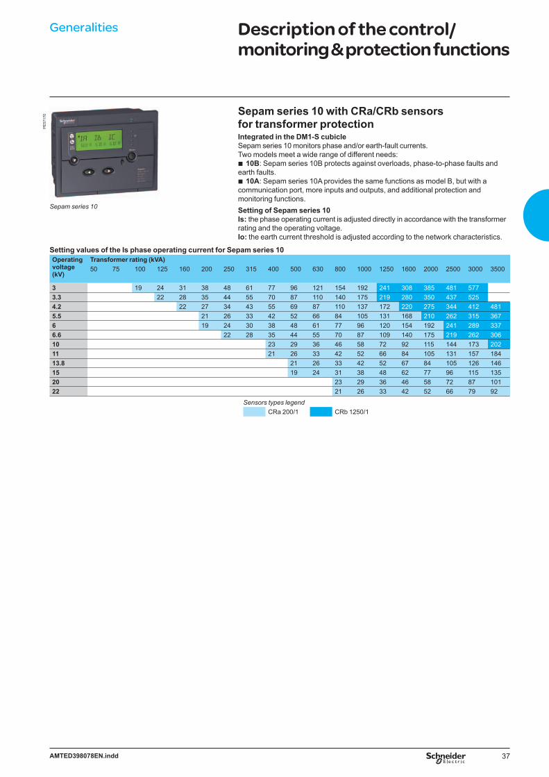
Sepam series 10 with CRa/CRb sensors for transformer protectionIntegrated in the DM1-S cubicleSepam series 10 monitors phase and/or earth-fault currents. Two models meet a wide range of different needs:
10B: Sepam series 10B protects against overloads, phase-to-phase faults and earth faults.
10A: Sepam series 10A provides the same functions as model B, but with a communication port, more inputs and outputs, and additional protection and monitoring functions.Setting of Sepam series 10Is: the phase operating current is adjusted directly in accordance with the transformer rating and the operating voltage.Io: the earth current threshold is adjusted according to the network characteristics.
Setting values of the Is phase operating current for Sepam series 10Operating voltage (kV)
Transformer rating (kVA)50 75 100 125 160 200 250 315 400 500 630 800 1000 1250 1600 2000 2500 3000 3500
3 19 24 31 38 48 61 77 96 121 154 192 241 308 385 481 5773.3 22 28 35 44 55 70 87 110 140 175 219 280 350 437 5254.2 22 27 34 43 55 69 87 110 137 172 220 275 344 412 4815.5 21 26 33 42 52 66 84 105 131 168 210 262 315 3676 19 24 30 38 48 61 77 96 120 154 192 241 289 3376.6 22 28 35 44 55 70 87 109 140 175 219 262 30610 23 29 36 46 58 72 92 115 144 173 20211 21 26 33 42 52 66 84 105 131 157 18413.8 21 26 33 42 52 67 84 105 126 14615 19 24 31 38 48 62 77 96 115 13520 23 29 36 46 58 72 87 10122 21 26 33 42 52 66 79 92
Sensors types legendCRa 200/1 CRb 1250/1
b
b
PE
5717
0
Sepam series 10

38 AMTED398078EN.indd
Generalities Description of the control/monitoring & protection functions
Protection type Code Protection unitsSepam VIPseries 10 series 20 series 40 series 80 35 300
Three-phase overcurrent 50 - 51 b b b b b (2) b (1)
Zero-sequence overcurrent 50N - 51N b b b b b (3) b (1)
Directional zero-sequence current 67N b bUndervoltage 27 b bOvervoltage 59 b bThermal image 49 b b b bZero-sequence overvoltage 59N b bNegative sequence overcurrent 46 b b bLong start-up and rotor blocking 51LR b b bMaximum number of start-ups 66 b b bSingle-phase undercurrent 37 b b bCommunication b b b b
(1) DT, EI, SI, VI and RI trip curves. (2) Inverse curve suited to transformer protection.(3) DT trip curve.
CRa, CRb, CRc current sensor
General common selection of protection units
Current sensor for VIP 35 and VIP 300LL and Sepam series 10
Type Dimensions (mm) Weight (kg)
Ratio of transformation
Class of precision VIP 35 VIP 300LL Sepam 10External Ø
Internal Ø
Thickness(without fastening)
CRa 143.5 81 37.5 2.18 1/200 ± 2% from 10 A to 100 A± 1% from 100 A to 1600 A
On load 5.7 Ω (cal. x 1) b b
± 1% from 10 A to 10 kA On load 0.67 Ω (cal. x 4)CRb 143.5 81 37.5 1.26 1/1250 ± 1% from 10 A to 11 kA On load 5.7 Ω (cal. x 1) b b
± 1 % from 10 A to 25 kA On load 0.67 Ω (cal. x 4)CRc 143.5 81 37.5 2 S1-S2: 1/200
S1-S3: 1/500
S1-S2:± 5% from 10 A to 80 A± 2.5 % from 80 A to 600 AS1-S3:± 2% from 20 A to 2200 A
On load 0.6 Ω b
DE
5840
2

39AMTED398078EN.indd
MT1
1325
Generalities LPCT protection chainTLP130, CLP2 sensors and Sepam series 20, series 40, series 80 protection units
LPCT sensors are voltage-output current sensors (Low Power Current Transformer) compliant with the IEC 60044-8 standard.These sensors are designed to measure rated current between 5 A and 630 A, with a ratio of 100 A / 22.5 mV.Sepam series 20, series 40, series 80 protection units are at the heart of the LPCT protection chain.Sepam series 20, series 40, series 80 performs the following functions:
acquisition of phase currents measured by the LPCT sensorsutilization of measurements by the protection functionstripping of the breaking device in case of fault detection.
AdvantagesConsistent protection chain with the same sensor measures phase currents
from 5 A to 630 A Simple to install and implement:installation of LPCT sensorsTLP130 is installed around MV cableCLP2 is installed on the MV circuitLPCT connected directly to Sepam series 20, series 40, series 80accessories available to test the LPCT protection chain by secondary current
injection.LPCTs range of use
LPCT measuring and protection function guaranteeing the accuracy up to the short-time current. Following the range of use of LPCT:
from 5 A up to 1250 A respecting the error limits imposed by the accuracy class 0,5 from 1250 A up to 50 kA respecting the error limits imposed by the accuracy class 5P.
DE
5840
5EN Ratio error
A
5.004.754.504.254.003.753.503.253.002.752.502.252.001.751.50
Protective class 5P
Measuring class 0.5
1.251.000.750.500.25
5 20 100 1000 1250 2000 3000 31500 40000 50000
Optimized integration of functions:measurement of phase rated currents as of 25 A that is set by micro-switchmonitoring of LPCT sensor by Sepam series 20, series 40, series 80 (detection of
phase loss).
Connections1 LPCT sensor, equipped with a shielded cable fitted with an RJ45 connector to be connected directly to the card 32 Sepam series 20, series 40, series 80 protection unit3 Card interface that adapts the voltage delivered by the LPCT sensors, with microswitch setting of rated current.
CCA671 card for series 80CCA670 card for series 20 and 40.
Testing and injection4 CCA613 remote test plug, flush-mounted in front panel of cubicle, equipped with a 3-m cord to be connected to the CCA670 connector test socket (9-pin Sub D)5 ACE917 injection interface, used to test the LPCT protection chain with a standard injection box6 Standard 1A injection box.
bbb
b
bv--vv
b
vv
bvv
vv
PE
5717
2P
E88
012
Standardapplications
Sepam series 20
Customapplications
Sepam series 80
Demandingapplications
Sepam series 40
PE
8801
1P
E88
010

40 AMTED398078EN.indd
Generalities Web Remote Monitoring
DescriptionThe EGX300 Web server device is industrialised for SM6-24 Web Remote Monitoring offer:
The EGX300 is an Ethernet-based device providing a simple transparent interface between Ethernet-based networks and field devices as protective relays (Sepam).
The EGX300 has the ability to be used as a simple web based monitoring solution providing real-time data views, on-board data logging/trending, and simple control for field devices.
The DM range of circuit breakers cubicles with Sepam ranges and one EGX300 per switchboard for remote monitoring via the Intranet
An RJ45 Ethernet connector on the front of the switchboard, directly accessiblefrom the front panel (option).For other SM6-24 configurations (with other devices or other Sepam product ranges), it is possible to integrate Web Remote Monitoring capability, consult your local Schneider Electric correspondent.
Range selectionThis chart presents the different SM6-24 cubicles proposed with an industrialisedWeb Remote Monitoring system.Description Type of units
Single-isolation circuit breaker unit DM1-ASingle-isolation circuit breaker unit, right or left outgoing line DM1-DWithdrawable single-isolation circuit breaker unit DM1-WWithdrawable single-isolation circuit breaker unit, right outgoing line DM1-ZDouble-isolation circuit breaker unit, right or left outgoing line DM2
Typical designYou need to have a Web server in only one CB unit to monitor the whole switchboard.
DE
5921
5EN Intranet, Ethernet TCP/IP
EGX300
EGX300
PSU 24 Vdc Modbus serial link (1)
Sepam
SepamSepamSepam
(1) Same cable CCR301 for RS 485 and PSU 24 V DC
b
b
b
bSM6 Web Remote Monitoring with front face Intranet connector
DE
5840
7
Functionalities provided
Instantaneous readingsDisplays automatically updated meter values
Circuit summary Displays the RMS current 3-phase average (A), the real power (kW), the power factor, the circuit breaker status (if applicable), etc.
Load current summaryDisplays the current RMS value for each phase (A), for all circuits
Demand current summaryDisplays the average demand current value for each phase (A), for all circuits
Power summaryDisplays the present demand (kW), the peak demand (kW) and the times and dates of the records
Energy summary Displays the energy (kWh) the reactive energy (kvarh), and the times and dates of the records
Instantaneous readings, all devices Basic historical data logging, energy and trendingDisplays automatically updated meter values for all the communicating devices in the equipment
Log displaysDisplays data as time curves, or tables
Export of data tablesAllows data tables to be exported in a standard Windows format

41AMTED398078EN.indd
SM6-24 Contents
Characteristics of the functional unitsFunctional units selection 42Automatic Transfer System 57Network remote control and monitoring 59Operating mechanisms 60Auxiliaries 63Current transformers 65Voltage transformers 67Protection of transformers 69Motors protection units 71Interlocks 73
42 AMTED398078EN.indd
Characteristics of the functional units
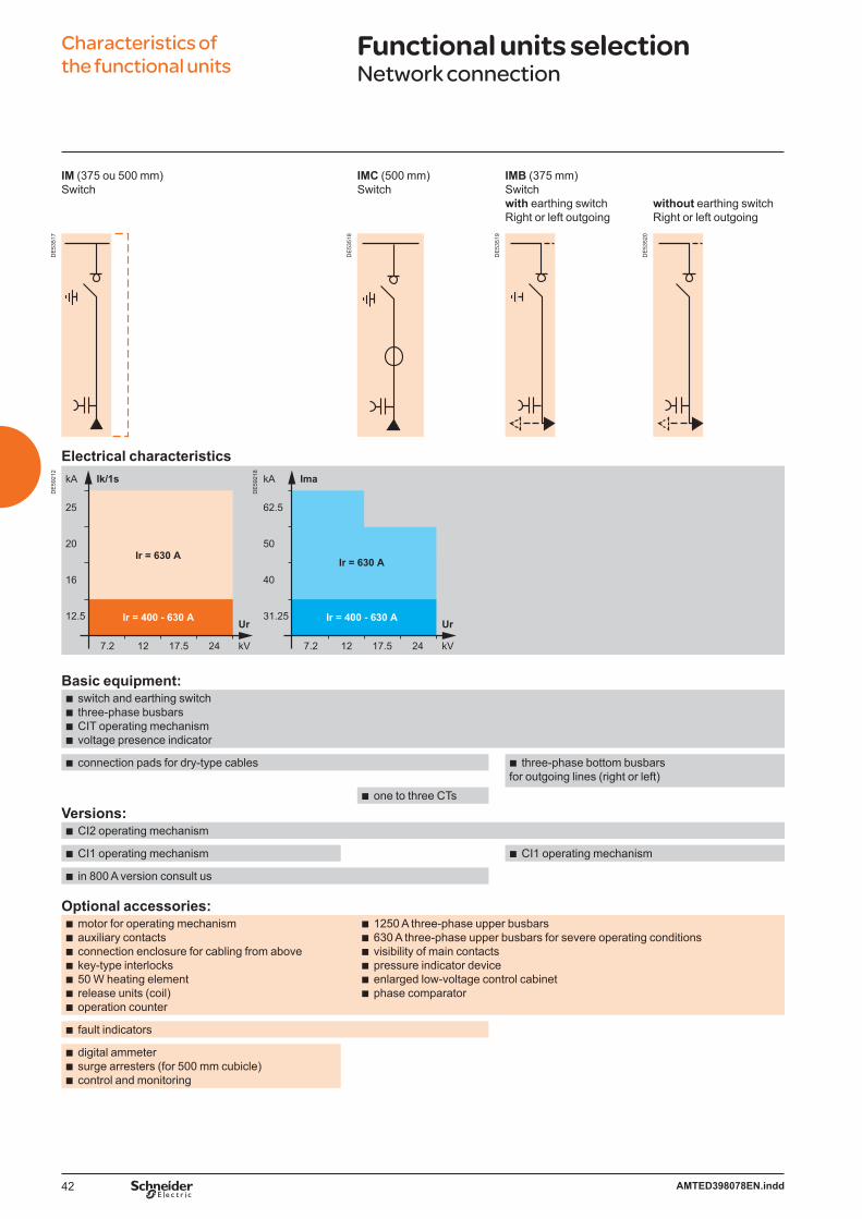
Functional units selection Network connection
IM (375 ou 500 mm)Switch
IMC (500 mm)Switch
IMB (375 mm)Switch with earthing switch Right or left outgoing
without earthing switch Right or left outgoing
DE
5351
7
DE
5351
8
DE
5351
9
DE
5352
0
Electrical characteristics
DE
5921
2
Ir = 400 - 630 A
25
20
16
12.5
7.2 12 17.5 24
Ir = 630 A
kA Ik/1s
kV
Ur Ir = 400 - 630 A
62.5
50
40
31.25
7.2 12 17.5 24
Ir = 630 A
kA Ima
kV
Ur
DE
5921
8
Basic equipment:switch and earthing switchthree-phase busbarsCIT operating mechanismvoltage presence indicator
bbbb
connection pads for dry-type cablesb three-phase bottom busbars for outgoing lines (right or left)b
one to three CTsb
Versions:CI2 operating mechanism b
CI1 operating mechanism b CI1 operating mechanism b
in 800 A version consult usb
Optional accessories:motor for operating mechanismauxiliary contactsconnection enclosure for cabling from abovekey-type interlocks50 W heating elementrelease units (coil)operation counter
bbbbbbb
1250 A three-phase upper busbars630 A three-phase upper busbars for severe operating conditionsvisibility of main contactspressure indicator deviceenlarged low-voltage control cabinetphase comparator
bbbbbb
fault indicatorsb
digital ammetersurge arresters (for 500 mm cubicle)control and monitoring
bbb

43AMTED398078EN.indd
Characteristics of the functional units
Functional units selectionFuse-switch protection
QM (375 or 500 mm)Fuse-switch combination unit
QMC (625 mm)Fuse-switch combination unit
QMB (375 mm)Fuse-switch combination unitOutgoing line right or left
DE
5352
2
DE
5352
3
DE
5352
4
Electrical characteristics
DE
5835
2
25
20
16
12.5
7.2 12 17.5 24
Ir = 200 A
kA Ik/1s
kV
Ur
25
20
16
12.5
7.2 12 17.5 24
Ir = 200 A
kA Isc
kV
Ur
DE
5921
9
Basic equipment:switch and earthing switchthree-phase busbarsCI1 operating mechanismvoltage presence indicatorequipment for three UTE or DIN striker fusesmechanical indication system for blown fuses
bbbbbb
connection pads for dry-type cablesdownstream earthing switch 2 kA rms making capacity
bb
three-phase bottom busbars for outgoing lines (right or left)
b
one to three CTsb
Version:CI2 operating mechanism b
Optional accessories:motor for operating mechanism auxiliary contactsconnection enclosure for cabling from abovekey-type interlocks50 W heating elementauxiliary contact for blown fusesUTE or DIN striker fusesrelease units (coil)digital ammetervisibility of main contactspressure indicator device1250 A three-phase upper busbars630 A three-phase upper busbars for severe operating conditions enlarged low-voltage control cabinet
bbbbbbbbbbbbbb

44 AMTED398078EN.indd
Characteristics of the functional units
Functional units selectionFuse-switch protection
PM (375 mm)Fused-switch unit
DE
5352
6
Electrical characteristics
DE
5921
7
25
20
16
12.5
7.2 12 17.5 24
Ir = 200 A
kA Ik/1s & Isc
kV
Ur
Basic equipment:switch and earthing switchthree-phase busbarsCIT operating mechanismvoltage presence indicatorconnection pads for dry-type cablesdownstream earthing switch 2 kA rms making capacityequipment for three UTE or DIN fuses
bbbbbbb
Optional accessories:motor for operating mechanismauxiliary contactsconnection enclosure for cabling from above key-type interlocks50 W heating elementmechanical indication system for blown fusesUTE or DIN fusesdigital ammetervisibility of main contactspressure indicator device1250 A three-phase upper busbars630 A three-phase upper busbars for severe operating conditionsenlarged low-voltage control cabinet
bbbbbbbbbbbbb

45AMTED398078EN.indd
Characteristics of the functional units
Functional units selectionContactor protection
CRM (750 mm)Contactor
CRM (750 mm)Contactor with fuses
DE
5352
7
DE
5352
8
Electrical characteristics
DE
5922
3
10
8
7.2 12
Ir = 400 A
kA Ik/1s & Isc
kV
Ur
DE
5922
4
25
20
16
12.5
7.2 12
Ir = 250 A
kA Isc
kV
Ur
Basic equipment:SF6 contactordisconnector and earthing switchthree-phase busbarscontactor operating mechanism with magnetic holding or contactor with mechanical latchingdisconnector operating mechanism CSone to three current transformers auxiliary contacts on contactorconnection pads for dry-type cablesvoltage presence indicatordownstream earthing switch 2 kA rms making capacityoperation counter on contactorenlarged low-voltage control cabinet
bbbbbbbbbbbb
equipment for three DIN fusesb
Optional accessories:cubicle:auxiliary contacts on the disconnectorprotection using Sepam programmable electronic unitone to three voltage transformerskey-type interlocks50 W heating element1250 A three-phase upper busbarscontactor:mechanical interlocking
bvvvvvv
bv
DIN fusesb
46 AMTED398078EN.indd
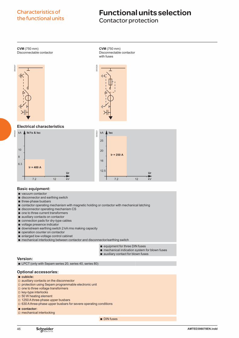
Characteristics of the functional units
Functional units selectionContactor protection
CVM (750 mm)Disconnectable contactor
CVM (750 mm)Disconnectable contactor with fuses
DE
5352
7
DE
5352
8
Electrical characteristics
DE
5922
0
10
8
6.3
7.2 12
10
8
6.3
7.2 12
Ir = 400 A
kA Ik/1s & Isc
kV
Ur
DE
5922
1
7.2 12
Ir = 250 A
kA Isc
kV
Ur
25
20
16
12.5
Basic equipment:vacuum contactordisconnector and earthing switchthree-phase busbarscontactor operating mechanism with magnetic holding or contactor with mechanical latchingdisconnector operating mechanism CSone to three current transformers auxiliary contacts on contactorconnection pads for dry-type cablesvoltage presence indicatordownstream earthing switch 2 kA rms making capacityoperation counter on contactorenlarged low-voltage control cabinetmechanical interlocking between contactor and disconnector/earthing switch
bbbbbbbbbbbbb
equipment for three DIN fusesmechanical indication system for blown fusesauxiliary contact for blown fuses
bbb
Version:LPCT (only with Sepam series 20, series 40, series 80)b
Optional accessories:cubicle:auxiliary contacts on the disconnectorprotection using Sepam programmable electronic unitone to three voltage transformerskey-type interlocks50 W heating element1250 A three-phase upper busbars630 A three-phase upper busbars for severe operating conditionscontactor:mechanical interlocking
bvvvvvvv
bv
DIN fusesb

47AMTED398078EN.indd
Characteristics of the functional units
Functional units selectionSF6 type circuit breaker protection
DM1-A (750 mm)Single-isolation disconnectable CB
DM1-D (750 mm)Single-isolation disconnectable CBOutgoing line on right
DM1-D (750 mm)Single-isolation disconnectable CBOutgoing line on left
DE
5353
1
DE
5353
2
DE
5353
3
Electrical characteristics
DE
5922
5-Is
c
Ir = 400 - 630 - 1250 A
25
20
16
12.5
7.2 12 17.5 24
Ir = 630 - 1250 A
kA Ik/1s & Isc
kV
Ur
Basic equipment:SF1 disconnectable circuit breakerdisconnector and earthing switchthree-phase busbarscircuit breaker operating mechanism RIdisconnector operating mechanism CSvoltage presence indicatorthree CTsauxiliary contacts on circuit breakermechanical interlocking between circuit breaker and disconnector
bbbbbbbbb
connection pads for dry-type cablesdownstream earthing switch 2 kA rms making
capacity at 630 A and 25 kA rms making capacity at 1250 A
bb
three-phase bottom busbarsb
Version:LPCT (only with Sepam series 20, series 40, series 80)b
SFset circuit breaker disconnectable (only for the 400-630 A performances)b
Optional accessories:cubicle:auxiliary contacts on the disconnectorconnection enclosure for cabling from aboveprotection using Sepam programmable electronic unitthree voltage transformerskey-type interlocks50 W heating elementsurge arresters (only DM1-A)1250 A three-phase upper busbars at Ir 630 A630 A three-phase upper busbars for severe operating conditionsenlarged low-voltage control cabinet
bvvvvvvvvvv
circuit breaker:motor for operating mechanismrelease units (coil)operation counter on manual operating mechanism
bvvv

48 AMTED398078EN.indd
Characteristics of the functional units
Functional units selectionSF6 type circuit breaker protection
DM1-S (750 mm)Single-isolation disconnectable CB with independent protection
DM2 (750 mm)Double-isolation disconnectable CB Outgoing line on right
DM2 (750 mm)Double-isolation disconnectable CBOutgoing line on left
DE
5836
0
DE
5353
6
DE
5353
7
Electrical characteristics
DE
5921
2-Is
c
Ir = 400 - 630 A
25
20
16
12.5
7.2 12 17.5 24
Ir = 630 A
kA Ik/1s & Isc
kV
Ur
Basic equipment:SF1 disconnectable circuit breakerdisconnector and earthing switch three-phase busbarscircuit breaker operating mechanism RIdisconnector operating mechanism CSauxiliary contacts on circuit breakermechanical interlocking between circuit breaker and disconnector
bbbbbbb
VIP relaythree CR sensors for VIP relay protectionvoltage presence indicatorconnection pads for dry-type cablesdownstream earthing switch 2 kA rms making capacity
bbbbb
three CTsb
Version:Sepam series 10 with auxiliary supply and
three CR sensorsb
Optional accessories:cubicle:three voltage transformerskey-type interlocks
bvv
cubicle:protection using Sepam programmable electronic unitauxiliary contacts on disconnectors2 voltage transformers phase-to-phase or 3 voltage transformers phase-to-earth
bvvv
1250 A three-phase upper busbars at Ir 630 A630 A three-phase upper busbars for severe operating conditionsenlarged low-voltage control cabinetconnection enclosure for cabling from above50 W heating element
vvvvv
circuit breaker:motor for operating mechanismrelease units (coil)operation counter on manual operating mechanism
bvvv
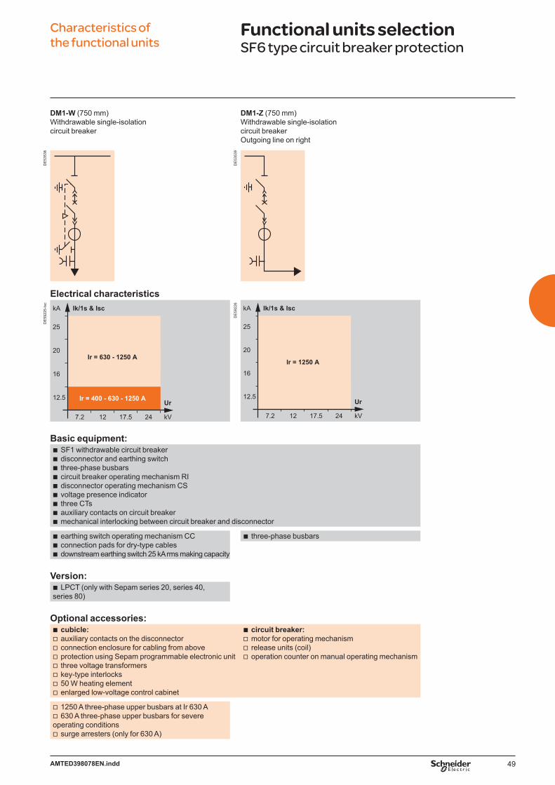
49AMTED398078EN.indd
Characteristics of the functional units
Functional units selectionSF6 type circuit breaker protection
DM1-W (750 mm)Withdrawable single-isolation circuit breaker
DM1-Z (750 mm)Withdrawable single-isolation circuit breaker Outgoing line on right
DE
5353
8
DE
5353
9
Electrical characteristics
DE
5922
5-Is
c
Ir = 400 - 630 - 1250 A
25
20
16
12.5
7.2 12 17.5 24
Ir = 630 - 1250 A
kA Ik/1s & Isc
kV
Ur
DE
5922
6
25
20
16
12.5
7.2 12 17.5 24
Ir = 1250 A
kA Ik/1s & Isc
kV
Ur
Basic equipment:SF1 withdrawable circuit breakerdisconnector and earthing switch three-phase busbarscircuit breaker operating mechanism RIdisconnector operating mechanism CSvoltage presence indicatorthree CTsauxiliary contacts on circuit breakermechanical interlocking between circuit breaker and disconnector
bbbbbbbbb
earthing switch operating mechanism CCconnection pads for dry-type cablesdownstream earthing switch 25 kA rms making capacity
bbb
three-phase busbarsb
Version:LPCT (only with Sepam series 20, series 40,
series 80)b
Optional accessories:cubicle:auxiliary contacts on the disconnector connection enclosure for cabling from aboveprotection using Sepam programmable electronic unit three voltage transformers key-type interlocks50 W heating elementenlarged low-voltage control cabinet
bvvvvvvv
circuit breaker:motor for operating mechanismrelease units (coil)operation counter on manual operating mechanism
bvvv
1250 A three-phase upper busbars at Ir 630 A630 A three-phase upper busbars for severe
operating conditionssurge arresters (only for 630 A)
vv
v

50 AMTED398078EN.indd
Characteristics of the functional units
Functional units selectionVacuum type circuit breaker protection
DMV-A (625 mm)Single-isolation circuit breaker
DMV-D (625 mm)Single-isolation circuit breakerOutgoing line on right
DMV-S (625 mm)Single-isolation circuit breaker with independent protection
DMVL-A (750 mm)Single-isolation disconnectablecircuit breaker
DE
5354
1
DE
5354
2
DE
5354
3
DE
5353
5
Electrical characteristics
DE
5922
7
Ir = 400 - 630 - 1250 A
25
20
16
12.5
7.2 12 17.5 24
Ir = 630 - 1250 A
kA Ik/1s & Isc
kV
Ur
DE
5922
8
25
20
16
12.5
7.2 12 17.5 24
Ir = 630 A
kA Ik/1s & Isc
kV
Ur
Basic equipment:Evolis circuit breaker frontalswitch and earthing switch for 400 - 630 Adisconnector and earthing switch for 1250 Athree-phase busbarscircuit breaker operating mechanism P2disconnector and switch operating mechanism CITvoltage presence indicatorauxiliary contacts on circuit breaker
bbbbbbbb
mechanical interlocking between circuit breaker and disconnector
Evolis circuit breaker lateral disconnectable
disconnector and earthing switchthree-phase busbarscircuit breaker operating mechanism
RIdisconnector operating mechanism
CSvoltage presence indicatorauxiliary contacts on circuit breaker3 CTs
b
b
bbb
b
bbb
3 CTsSepam series 20 programmable electronic unit
bb
3 CR sensors for VIP relayVIP protection relay
bb
connection pads for dry-type cables
downstream earthing switch 25 kA rms making capacity
b
b
connection pads for dry-type cablesb
downstream earthing switch 25 kA rms making capacityb downstream earthing switch
2 kA rms making capacityb
Optional accessories:cubicle:auxiliary contacts on the disconnectorconnection enclosure for cabling from abovethree voltage transformerskey-type interlocks50 W heating element1250 A three-phase upper busbars at Ir 630 A
bvvvvvv
circuit breaker:motor for operating mechanismrelease units (coil)operation counter on manual operating mechanism
bvvv
630 A three-phase upper busbars for severe operating conditionsenlarged low-voltage control cabinet
vv
cubicle :Sepam relay protection surge arresters
bvv

51AMTED398078EN.indd
Characteristics of the functional units
Functional units selectionMV metering
CM (375 mm)Voltage transformersfor mains with earthedneutral system
CM2 (500 mm)Voltage transformers for mains with insulatedneutral system
DE
5354
6
DE
5354
7
Electrical characteristics
DE
5835
9
25
20
16
12.5
7.2 12 17.5 24
Ir = 50 A
kA Ik/1s
kV
Ur
Basic equipment:disconnector and earthing switchthree-phase busbarsoperating mechanism CSLV circuit isolation switchLV fusesthree 6.3 A UTE or DIN type fuses
bbbbbb
three-voltage transformers (phase-to-earth)b two voltage
transformers (phase-to-phase)
b
Optional accessories:auxiliary contactsconnection enclosure for cabling from above50 W heating elementmechanical signalling and auxiliary contact for blown fuses1250 A three-phase upper busbars630 A three-phase upper busbars for severe operating conditionsenlarged low-voltage control cabinet
bbbbbbb
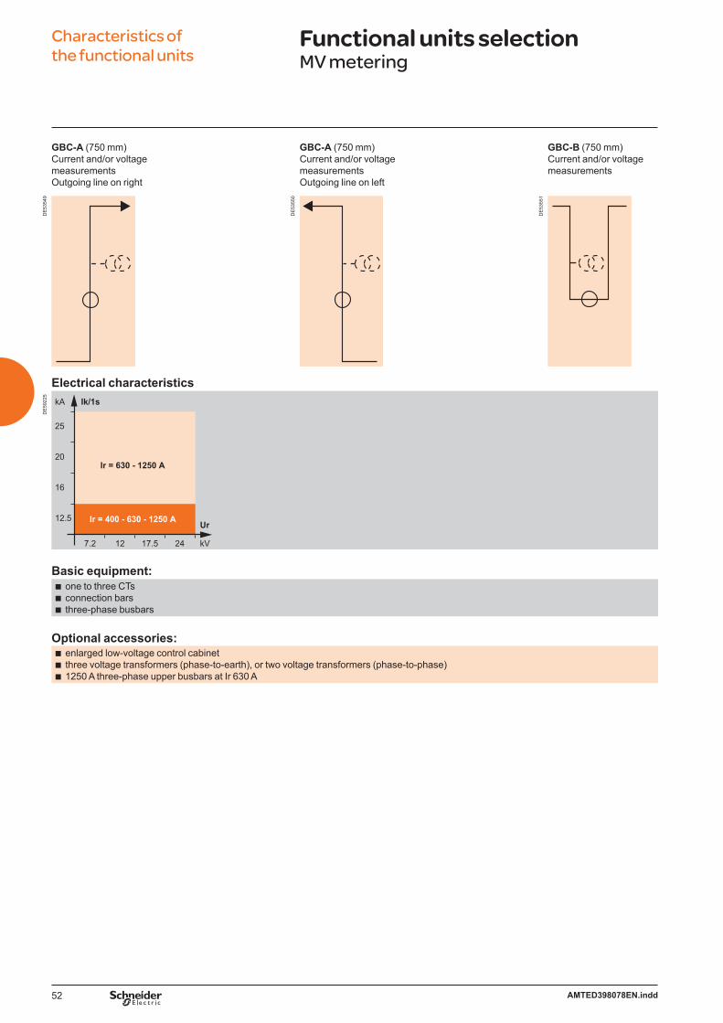
52 AMTED398078EN.indd
Characteristics of the functional units
Functional units selectionMV metering
GBC-A (750 mm)Current and/or voltage measurementsOutgoing line on right
GBC-A (750 mm)Current and/or voltage measurementsOutgoing line on left
GBC-B (750 mm)Current and/or voltage measurements
DE
5354
9
DE
5355
0
DE
5355
1
Electrical characteristics
DE
5922
5
Ir = 400 - 630 - 1250 A
25
20
16
12.5
7.2 12 17.5 24
Ir = 630 - 1250 A
kA Ik/1s
kV
Ur
Basic equipment:one to three CTsconnection barsthree-phase busbars
bbb
Optional accessories:enlarged low-voltage control cabinetthree voltage transformers (phase-to-earth), or two voltage transformers (phase-to-phase)1250 A three-phase upper busbars at Ir 630 A
bbb
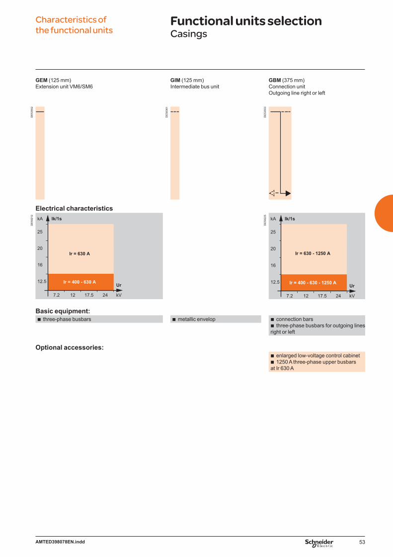
53AMTED398078EN.indd
Characteristics of the functional units
Functional units selectionCasings
GEM (125 mm)Extension unit VM6/SM6
GIM (125 mm)Intermediate bus unit
GBM (375 mm)Connection unitOutgoing line right or left
DE
5355
2
DE
5836
1
DE
5355
3
Electrical characteristics
DE
5921
2
Ir = 400 - 630 A
25
20
16
12.5
7.2 12 17.5 24
Ir = 630 A
kA Ik/1s
kV
Ur
DE
5922
5
Ir = 400 - 630 - 1250 A
25
20
16
12.5
7.2 12 17.5 24
Ir = 630 - 1250 A
kA Ik/1s
kV
Ur
Basic equipment:three-phase busbarsb metallic envelopb connection bars
three-phase busbars for outgoing linesright or left
bb
Optional accessories:enlarged low-voltage control cabinet1250 A three-phase upper busbars
at Ir 630 A
bb

54 AMTED398078EN.indd
Characteristics of the functional units
Functional units selectionCasings
GAM2 (375 mm)Incoming-cable-connection unit
GAM (500 mm)Incoming-cable-connection unit
DE
5355
4
DE
5355
5
Electrical characteristics
DE
5921
2
Ir = 400 - 630 A
25
20
16
12.5
7.2 12 17.5 24
Ir = 630 A
kA Ik/1s
kV
Ur
DE
5922
5
Ir = 400 - 630 - 1250 A
25
20
16
12.5
7.2 12 17.5 24
Ir = 630 - 1250 A
kA Ik/1s
kV
Ur
Basic equipment:three-phase busbarsvoltage presence indicatorconnection pads for dry-type cablesconnection bars
bbbb
operating mechanism CCdownstream earthing switch 25 kA rms making
capacity
bb
Optional accessories:enlarged low-voltage control cabinetconnection enclosure for cabling from above50 W heating elementfault indicatordigital ammeter1250 A three-phase upper busbars at Ir 630 A
bbbbbb
auxiliary contactssurge arresterskey-type interlocks
bbb

55AMTED398078EN.indd
Characteristics of the functional units
Functional units selectionOther functions
SM (375 or 500(1) mm)Disconnector unit
TM (375 mm) MV/LV transformer unitfor auxiliaries
EMB (375 mm)Busbars earthing compartment
DE
5355
6
DE
5355
7
DE
5355
8
Electrical characteristics
DE
5922
5
Ir = 400 - 630 - 1250 A
25
20
16
12.5
7.2 12 17.5 24
Ir = 630 - 1250 A
kA Ik/1s
kV
Ur
DE
5835
9
25
20
16
12.5
7.2 12 17.5 24
Ir = 50 A
kA Ik/1s
kV
Ur
DE
5921
2
Ir = 400 - 630 A
25
20
16
12.5
7.2 12 17.5 24
Ir = 630 A
kA Ik/1s
kV
Ur
Basic equipment:disconnector and earthing switchthree-phase busbarsoperating mechanism CS
bbb
earthing switchconnection barsoperating mechanism CITinstallation on 630 A IM 375 mm or
DM1-A units (except additional enclosure or connection enclosure for cabling from above)
require an key-type interlocks adapted to the switchboard network
bbbb
b
connection pads for dry-type cablesvoltage presence indicator
bb
two 6.3 A fuses, UTE or DIN typeLV circuit isolating switchone voltage transformer
(phase-to-phase)
bbb
Optional accessories:auxiliary contacts enlarged low-voltage control cabinetkey-type interlocks50 W heating element1250 A three-phase upper busbars at Ir 630 A630 A three-phase upper busbars for severe operating conditions
bbbbbb
auxiliary contactsb
connection enclosure for cabling from abovedigital ammeter
bb
mechanical indication system and auxiliary contacts for blown fuses
connection enclosure for cabling from above
b
b
(1) only for 1250 A units.
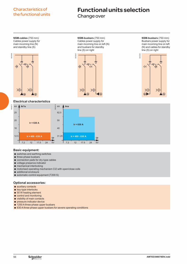
56 AMTED398078EN.indd
Characteristics of the functional units
Functional units selectionChange over
NSM-cables (750 mm)Cables power supply for main incoming line (N)and standby line (S)
NSM-busbars (750 mm) Cables power supply for main incoming line on left (N)and busbars for standby line (S) on right
NSM-busbars (750 mm) Busbars power supply for main incoming line on left (N) and cables for standby line (S) on right
DE
5355
9
DE
5840
1
DE
5356
1
Electrical characteristics
DE
5921
2
Ir = 400 - 630 A
25
20
16
12.5
7.2 12 17.5 24
Ir = 630 A
kA Ik/1s
kV
Ur Ir = 400 - 630 A
62.5
50
40
31.25
7.2 12 17.5 24
Ir = 630 A
kA Ima
kV
Ur
DE
5921
8
Basic equipment:switches and earthing switchesthree-phase busbarsconnection pads for dry-type cablesvoltage presence indicatormechanical interlockingmotorised operating mechanism CI2 with open/close coilsadditional enclosureautomatic-control equipment (T200 S)
bbbbbbbb
Optional accessories:auxiliary contactskey-type interlocks50 W heating elementcontrol and monitoringvisibility of main contactspressure indicator device1250 A three-phase upper busbars630 A three-phase upper busbars for severe operating conditions
bbbbbbbb

57AMTED398078EN.indd
Characteristics of the functional units
Automatic Transfer SystemWith NSM unit
Network back up
DE
5599
1EN
Voltage on SW1Vn
0V
T1 TR
TR
SW1C
O
T2SW2C
O
TR: transfer switch response time (< 180 ms - depending on switchgear).b Setting of time delay before switching: configurable from 0.1 s to 2 s (T1) with step of 100 ms.b Setting of time delay for return to the initial state: configurable from 5 s to 120 s (T2) with step of 5 s.b Transfer switch configurable with SW1VSW2 or SW2VSW1.Note: in bold = default configuration.
DE
5836
2EN
SW1 SW2
Line 1 Line 2
Generator back up
DE
5599
2EN
Voltage on SW1
Command of the generator
Voltage on generatorT2
Vn
0V
1
0
Vg
0V
T1
6s
TR
TR
SW1C
O
T3SW2C
O
TR: transfer switch response time (< 180 ms - depending on switchgear).b Setting of time delay before switching to the generator: configurable from 1 s to 15 s (T1) with step of 1 s.b Start up of the generator (T2), depending on kind of generator, not configurable (time max. to wait: 30 s).b Switching when the generator voltage is present.b Setting of time delay for return to the initial state: configurable from 60 s to 120 s with step of 5 s (T3).b Stopping the generator 6 s after switching.Note: in bold = default configuration.
DE
5836
3EN
SW1 SW2
GLine
Transfer switch (ACO 1/2) ACO: Automatic Change-OverThe transfer switch automatic control system gives automatic control and management of sources in the MV secondary distribution network with voltage presence detectors.Operating modesOperating mode is selected using the Easergy T200 S configuration tool.
Semi-Auto mode, SW1 XV SW2When the voltage disappears on the channel in service, the automatic control switches to the other channel after a time delay T1. The automatic control does not switch back, unless there is a voltage break on the new channel in service.
Mode SW1 V SW2, (SW2 V SW1)The automatic control only switches once from channel 1 or 2 to the back up channel.
Mode Auto-SW1 or Auto-SW2Channel 1 or 2 is priority if its MV voltage is OK. After switching to the back up channel, the mode switches back to the priority channel if the MV voltage on this channel is OK for a period T2.
Transfer time SW1 V SW2 for all modesIt is between 0.34 s to 2.24 s depending on the set values.
Switching sequenceSwitching takes place if the following conditions are fulfilled:automatic control onSW1 open/SW2 closed or SW1 closed/SW2 open“transfer locking” off“earthing switch” on both channels offMV voltage on the channel in service is absentMV voltage on the other channel is presentno fault current.Switching back to the main channel in “AUTO” modes is executed if:the priority channel is openthe MV voltage on the priority channel is OK for a time period of T2.
The closing order on the back up channel is given after confirming the opening of the channel in service.Source transfer lockingA digital input prohibits orders from the local control panel, the automatic control systems and the remote control supervisor.This input is generally connected to the downstream circuit breaker.
b
b
b
b
bvvvvvvvbvv
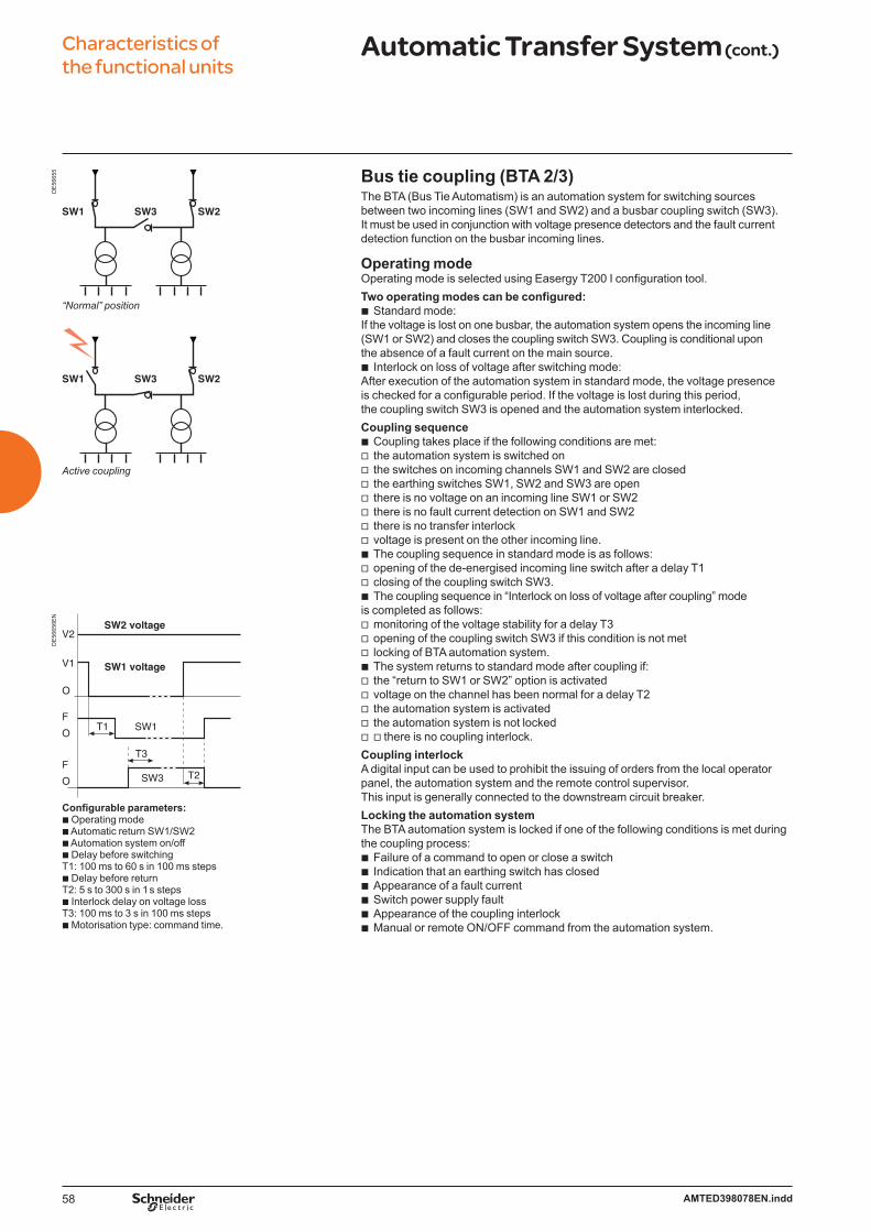
58 AMTED398078EN.indd
Characteristics of the functional units
Automatic Transfer System (cont.)D
E56
655
SW1 SW2SW3
SW1 SW2SW3
“Normal” position
Active coupling
DE
5665
6EN
Configurable parameters:b Operating modeb Automatic return SW1/SW2b Automation system on/offb Delay before switching T1: 100 ms to 60 s in 100 ms stepsb Delay before returnT2: 5 s to 300 s in 1 s stepsb Interlock delay on voltage loss T3: 100 ms to 3 s in 100 ms stepsb Motorisation type: command time.
Bus tie coupling (BTA 2/3) The BTA (Bus Tie Automatism) is an automation system for switching sources between two incoming lines (SW1 and SW2) and a busbar coupling switch (SW3).It must be used in conjunction with voltage presence detectors and the fault current detection function on the busbar incoming lines.
Operating modeOperating mode is selected using Easergy T200 I configuration tool.Two operating modes can be configured:
Standard mode:If the voltage is lost on one busbar, the automation system opens the incoming line (SW1 or SW2) and closes the coupling switch SW3. Coupling is conditional upon the absence of a fault current on the main source.
Interlock on loss of voltage after switching mode:After execution of the automation system in standard mode, the voltage presence is checked for a configurable period. If the voltage is lost during this period, the coupling switch SW3 is opened and the automation system interlocked.Coupling sequence
Coupling takes place if the following conditions are met:the automation system is switched onthe switches on incoming channels SW1 and SW2 are closed the earthing switches SW1, SW2 and SW3 are open there is no voltage on an incoming line SW1 or SW2 there is no fault current detection on SW1 and SW2there is no transfer interlock voltage is present on the other incoming line. The coupling sequence in standard mode is as follows:opening of the de-energised incoming line switch after a delay T1closing of the coupling switch SW3.The coupling sequence in “Interlock on loss of voltage after coupling” mode
is completed as follows:monitoring of the voltage stability for a delay T3opening of the coupling switch SW3 if this condition is not metlocking of BTA automation system.The system returns to standard mode after coupling if:the “return to SW1 or SW2” option is activated voltage on the channel has been normal for a delay T2the automation system is activatedthe automation system is not locked v there is no coupling interlock.
Coupling interlockA digital input can be used to prohibit the issuing of orders from the local operatorpanel, the automation system and the remote control supervisor. This input is generally connected to the downstream circuit breaker.Locking the automation systemThe BTA automation system is locked if one of the following conditions is met during the coupling process:
Failure of a command to open or close a switchIndication that an earthing switch has closed Appearance of a fault current Switch power supply fault Appearance of the coupling interlockManual or remote ON/OFF command from the automation system.
b
b
bvvvvvvvbvvb
vvvbvvvvv
bbbbbb
SW2 voltage
SW1 voltage
SW1
SW3 T2
V1
V2
O
F
O
F
O
T1
T3
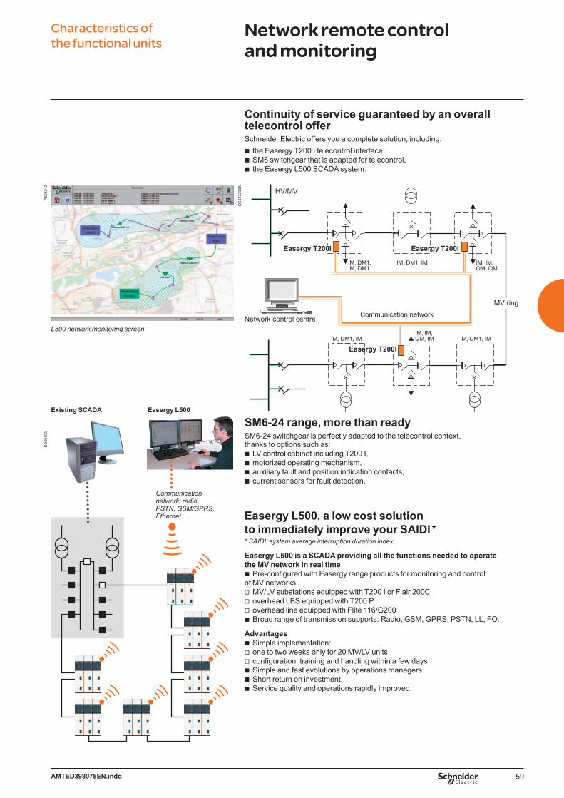
59AMTED398078EN.indd
Characteristics of the functional units
Network remote control and monitoring
Continuity of service guaranteed by an overall telecontrol offerSchneider Electric offers you a complete solution, including:
the Easergy T200 I telecontrol interface,SM6 switchgear that is adapted for telecontrol,the Easergy L500 SCADA system.
SM6-24 range, more than readySM6-24 switchgear is perfectly adapted to the telecontrol context,thanks to options such as:
LV control cabinet including T200 I,motorized operating mechanism,auxiliary fault and position indication contacts,current sensors for fault detection.
Easergy L500, a low cost solution to immediately improve your SAIDI ** SAIDI: system average interruption duration index
Easergy L500 is a SCADA providing all the functions needed to operate the MV network in real time
Pre-configured with Easergy range products for monitoring and control of MV networks:
MV/LV substations equipped with T200 I or Flair 200Coverhead LBS equipped with T200 Poverhead line equipped with Flite 116/G200Broad range of transmission supports: Radio, GSM, GPRS, PSTN, LL, FO.
AdvantagesSimple implementation:one to two weeks only for 20 MV/LV unitsconfiguration, training and handling within a few daysSimple and fast evolutions by operations managersShort return on investment Service quality and operations rapidly improved.
bbb
bbbb
b
vvvb
bvvbbb
Network control centre
HV/MV
Communication network
IM, DM1, IM, DM1
IM, DM1, IM IM, IM, QM, QM
IM, IM, QM, IM IM, DM1, IM
Easergy T200I
Easergy T200I
Easergy T200I
IM, DM1, IM
MV ring
DE
5372
9EN
DE
5840
3
Communication network: radio, PSTN, GSM/GPRS, Ethernet …
Easergy L500Existing SCADA
PE
5631
2
L500 network monitoring screen
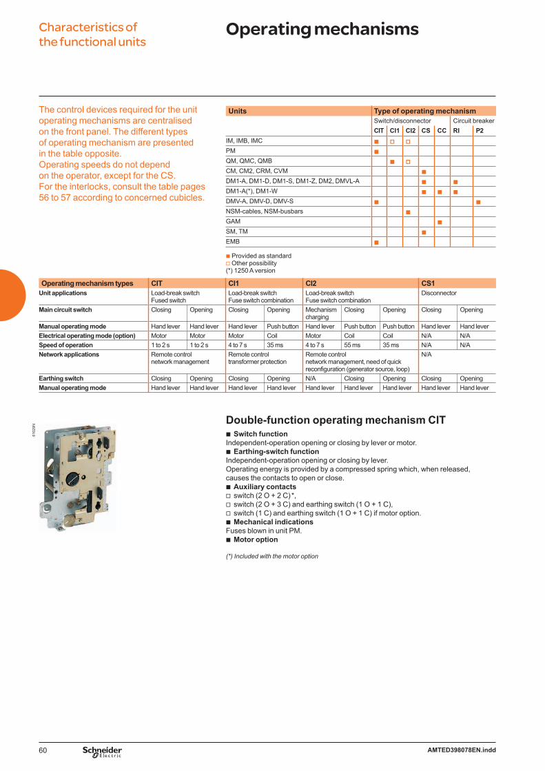
60 AMTED398078EN.indd
Characteristics of the functional units
Operating mechanisms
The control devices required for the unit operating mechanisms are centralised on the front panel. The different types of operating mechanism are presented in the table opposite. Operating speeds do not depend on the operator, except for the CS.For the interlocks, consult the table pages 56 to 57 according to concerned cubicles.
Units Type of operating mechanismSwitch/disconnector Circuit breakerCIT CI1 CI2 CS CC RI P2
IM, IMB, IMC b v vPM bQM, QMC, QMB b vCM, CM2, CRM, CVM bDM1-A, DM1-D, DM1-S, DM1-Z, DM2, DMVL-A b bDM1-A(*), DM1-W b b bDMV-A, DMV-D, DMV-S b bNSM-cables, NSM-busbars bGAM bSM, TM bEMB b
b Provided as standardv Other possibility(*) 1250 A version
Operating mechanism types CIT CI1 CI2 CS1Unit applications Load-break switch
Fused switchLoad-break switch Fuse switch combination
Load-break switch Fuse switch combination
Disconnector
Main circuit switch Closing Opening Closing Opening Mechanism charging
Closing Opening Closing Opening
Manual operating mode Hand lever Hand lever Hand lever Push button Hand lever Push button Push button Hand lever Hand leverElectrical operating mode (option) Motor Motor Motor Coil Motor Coil Coil N/A N/ASpeed of operation 1 to 2 s 1 to 2 s 4 to 7 s 35 ms 4 to 7 s 55 ms 35 ms N/A N/ANetwork applications Remote control
network managementRemote control transformer protection
Remote control network management, need of quick reconfiguration (generator source, loop)
N/A
Earthing switch Closing Opening Closing Opening N/A Closing Opening Closing OpeningManual operating mode Hand lever Hand lever Hand lever Hand lever Hand lever Hand lever Hand lever Hand lever Hand lever
Double-function operating mechanism CITSwitch function
Independent-operation opening or closing by lever or motor.Earthing-switch function
Independent-operation opening or closing by lever.Operating energy is provided by a compressed spring which, when released, causes the contacts to open or close.
Auxiliary contactsswitch (2 O + 2 C) *,switch (2 O + 3 C) and earthing switch (1 O + 1 C),switch (1 C) and earthing switch (1 O + 1 C) if motor option.Mechanical indications
Fuses blown in unit PM.Motor option
(*) Included with the motor option
b
b
bvvvb
b
6102
9N

61AMTED398078EN.indd
Characteristics of the functional units
Operating mechanisms61
032N
6103
1N61
033N
6103
0N Double-function operating mechanism CI1Switch function independent-operation closing by lever or motor.
Operating energy is provided by a compressed spring which, when released, causes the contacts to open to close.
independent-operation opening by push-button (O) or trip units.Earthing-switch function
Independent-operation closing and opening by lever.Operating energy is provided by a compressed spring which, when released, causes the contacts to open or close.
Auxiliary contactsswitch (2 O + 2 C) *, switch (2 O + 3 C) and earthing switch (1 O + 1 C),switch (1 C) and earthing switch (1 O + 1 C) if motor option,fuses blown (1 C).Mechanical indications
Fuses blown in units QM.Opening releasesshunt trip,undervoltage for unit QM.Motor option
(*) Included with the motor option.
Double-function operating mechanism CI2Switch function independent-operation closing in two steps:
1 - operating mechanism recharging by lever or motor,2 - stored energy released by push-button (I) or trip unit.
independent-operation opening by push-button (O) or trip unit.Earthing-switch function
Independent-operation closing and opening by lever.Operating energy is provided by a compressed spring which, when released, causes the contacts to open or close.
Auxiliary contactsswitch (2 O + 2 C) *, switch (2 O + 3 C) and earthing switch (1 O + 1 C),switch (1 C) and earthing switch (1 O + 1 C) if motor option.Opening release shunt tripClosing release shunt tripMotor option
(*) Included with the motor option.
Double-function operating mechanism CSSwitch and earth switch functions
Dependent-operation opening and closing by lever.Auxiliary contactsdisconnector (2 O + 2 C) for units DM1-A, DM1-D, DM1-W, DM2
and CRM without VT,disconnector (2 O + 3 C) and earthing switch (1 O + 1 C) for units
DM1-A, DM1-D, DM1-W, DM2 and CRM without VT,disconnector (1 O + 2 C) for units CM, CM2, TM, DM1-A, DM1-D, DM2
and CRM with VT.Mechanical indications
Fuses blown in units CM, CM2 and TM.
Single-function operating mechanism CCEarthing switch function
Independent-operation opening and closing by lever.Operating energy is provided by a compressed spring which, when released, provokes opening or closing of the contacts.
Auxiliary contactsEarthing switch (1 O + 1 C).
bv
vb
bvvvvb
bvvb
bv
vb
bvvvbbb
b
bv
v
v
b
b
b
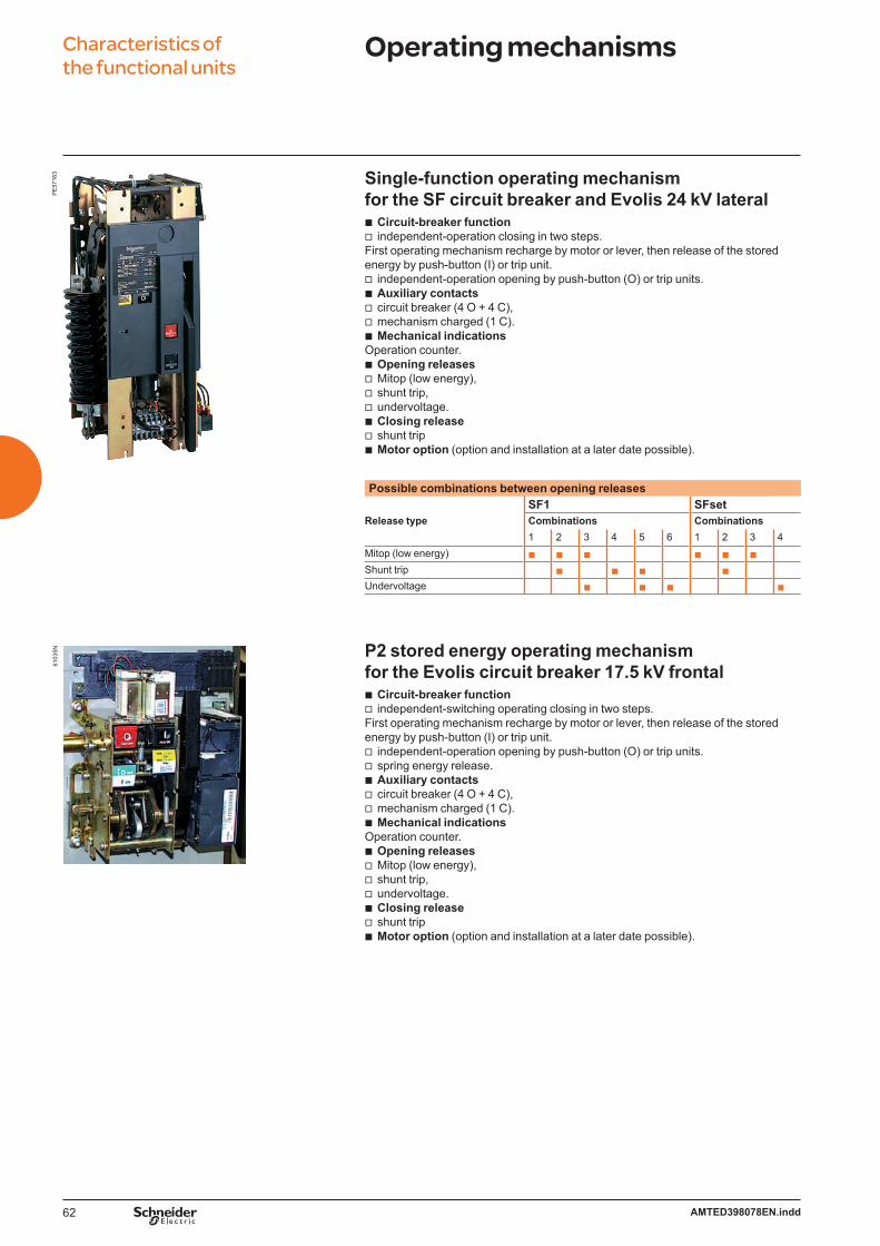
62 AMTED398078EN.indd
Characteristics of the functional units
Operating mechanisms
Single-function operating mechanism for the SF circuit breaker and Evolis 24 kV lateral
Circuit-breaker functionindependent-operation closing in two steps.
First operating mechanism recharge by motor or lever, then release of the stored energy by push-button (I) or trip unit.
independent-operation opening by push-button (O) or trip units.Auxiliary contactscircuit breaker (4 O + 4 C), mechanism charged (1 C).Mechanical indications
Operation counter.Opening releasesMitop (low energy),shunt trip,undervoltage.Closing release shunt tripMotor option (option and installation at a later date possible).
Possible combinations between opening releases
SF1 SFsetRelease type Combinations Combinations
1 2 3 4 5 6 1 2 3 4Mitop (low energy) b b b b b b
Shunt trip b b b b
Undervoltage b b b b
P2 stored energy operating mechanism for the Evolis circuit breaker 17.5 kV frontal
Circuit-breaker functionindependent-switching operating closing in two steps.
First operating mechanism recharge by motor or lever, then release of the stored energy by push-button (I) or trip unit.
independent-operation opening by push-button (O) or trip units.spring energy release.Auxiliary contactscircuit breaker (4 O + 4 C), mechanism charged (1 C).Mechanical indications
Operation counter.Opening releasesMitop (low energy),shunt trip,undervoltage.Closing release shunt tripMotor option (option and installation at a later date possible).
bv
vbvvb
bvvvbvb
bv
vvbvvb
bvvvbvb
6103
5NP
E57
163

63AMTED398078EN.indd
Characteristics of the functional units
Auxiliaries
Motor option and releases for switch-unitsThe operating mechanisms CIT, CI1 and CI2 may be motorised.
Un DC AC (50 Hz)*Power supply (V) 24 48 110 125 220 120 230 Motor option
(W) 200(VA) 200
Operating time for CIT 1 to 2 (s) 1 to 2 (s)Charging time for CI1, CI2 4 to 7 (s) 4 to 7 (s)
Opening releasesShunt trip (W) 200 250 300 300 300
(VA) 400 750Response time (ms) 35 35
UndervoltagePick-up (W) 160
(VA) 280 550Hold (W) 4
(VA) 50 40Response time (ms) 45 45
Closing releaseShunt trip (W) 200 250 300 300 300
(VA) 400 750Response time (ms) 55 55
* Please consult us for other frequencies.
Motor option and releases for SF6 type circuit breakers and Evolis 24 kV lateralOperating mechanism RI may be equipped with the motor option for the recharging function.
Un DC AC (50 Hz)*Power supply (V) 24 48 110 125 220 120 230 Motor option
(W) 300(VA) 380
Charging time (s) 15 15Opening releases
Mitop (low energy) (W) 3Response time (ms) 30 30
Shunt trip (W) 85(VA) 180
Response time (ms) 45 45Undervoltage
Pick-up (W) 160(VA) 280 550
Hold (W) 10(VA) 50 40
Response time (ms) 55 55Closing release
Shunt trip (W) 85(VA) 180
Response time (ms) 65 65
* Please consult us for other frequencies.
6103
6NP
E57
164
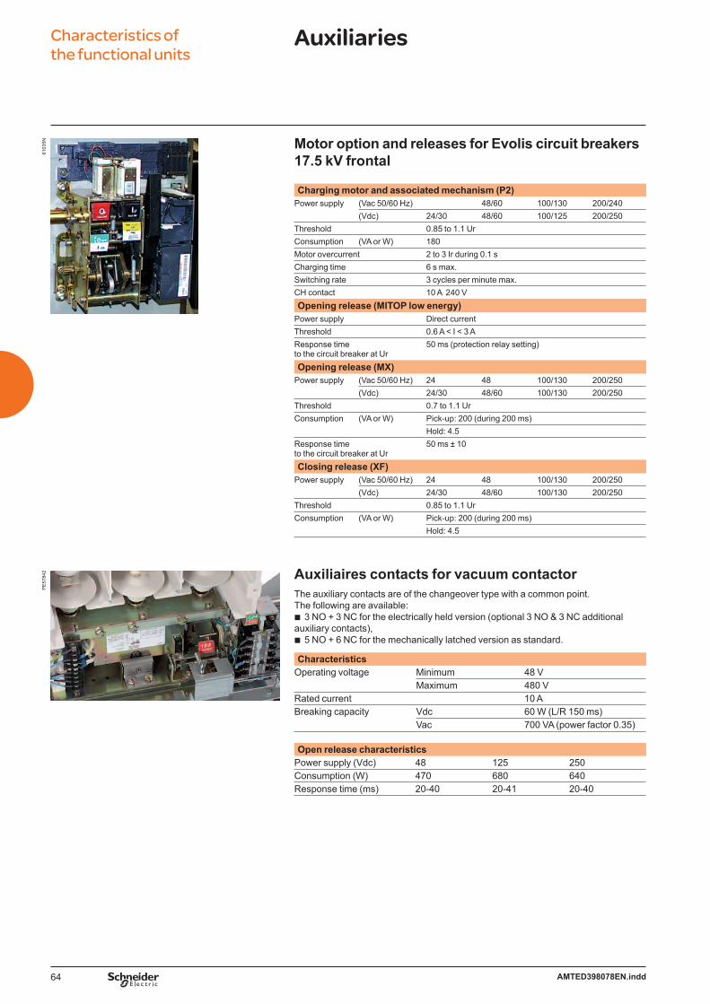
64 AMTED398078EN.indd
Characteristics of the functional units
Auxiliaries61
035N Motor option and releases for Evolis circuit breakers
17.5 kV frontal Charging motor and associated mechanism (P2)
Power supply (Vac 50/60 Hz) 48/60 100/130 200/240(Vdc) 24/30 48/60 100/125 200/250
Threshold 0.85 to 1.1 UrConsumption (VA or W) 180Motor overcurrent 2 to 3 Ir during 0.1 sCharging time 6 s max.Switching rate 3 cycles per minute max.CH contact 10 A 240 VOpening release (MITOP low energy)
Power supply Direct currentThreshold 0.6 A < I < 3 AResponse time to the circuit breaker at Ur
50 ms (protection relay setting)
Opening release (MX)Power supply (Vac 50/60 Hz) 24 48 100/130 200/250
(Vdc) 24/30 48/60 100/130 200/250Threshold 0.7 to 1.1 UrConsumption (VA or W) Pick-up: 200 (during 200 ms)
Hold: 4.5Response time to the circuit breaker at Ur
50 ms ± 10
Closing release (XF)Power supply (Vac 50/60 Hz) 24 48 100/130 200/250
(Vdc) 24/30 48/60 100/130 200/250Threshold 0.85 to 1.1 UrConsumption (VA or W) Pick-up: 200 (during 200 ms)
Hold: 4.5
Auxiliaires contacts for vacuum contactorThe auxiliary contacts are of the changeover type with a common point.The following are available:
3 NO + 3 NC for the electrically held version (optional 3 NO & 3 NC additional auxiliary contacts),
5 NO + 6 NC for the mechanically latched version as standard.
CharacteristicsOperating voltage Minimum 48 V
Maximum 480 VRated current 10 A Breaking capacity Vdc 60 W (L/R 150 ms) Vac 700 VA (power factor 0.35)
Open release characteristicsPower supply (Vdc) 48 125 250Consumption (W) 470 680 640Response time (ms) 20-40 20-41 20-40
b
b
PE
5784
2
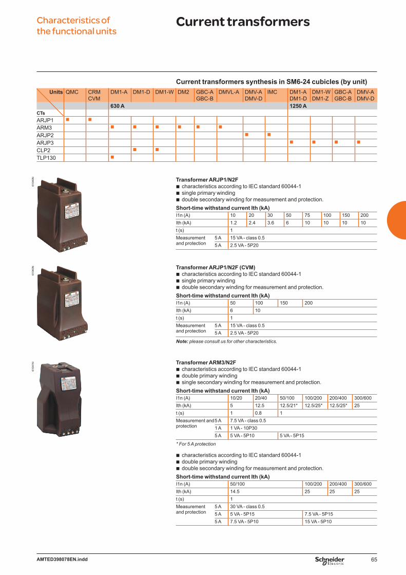
65AMTED398078EN.indd
Characteristics of the functional units
Current transformers61
040N
6104
0N61
041N
Current transformers synthesis in SM6-24 cubicles (by unit)Units QMC CRM
CVMDM1-A DM1-D DM1-W DM2 GBC-A
GBC-BDMVL-A DMV-A
DMV-DIMC DM1-A
DM1-DDM1-WDM1-Z
GBC-AGBC-B
DMV-ADMV-D
630 A 1250 ACTsARJP1 b b
ARM3 b b b b b b
ARJP2 b b
ARJP3 b b b b
CLP2 b b
TLP130 b
Transformer ARJP1/N2Fcharacteristics according to IEC standard 60044-1 single primary windingdouble secondary winding for measurement and protection.
Short-time withstand current Ith (kA)I1n (A) 10 20 30 50 75 100 150 200Ith (kA) 1.2 2.4 3.6 6 10 10 10 10t (s) 1Measurement and protection
5 A 15 VA - class 0.55 A 2.5 VA - 5P20
Transformer ARJP1/N2F (CVM)characteristics according to IEC standard 60044-1 single primary windingdouble secondary winding for measurement and protection.
Short-time withstand current Ith (kA)I1n (A) 50 100 150 200Ith (kA) 6 10t (s) 1Measurement and protection
5 A 15 VA - class 0.55 A 2.5 VA - 5P20
Note: please consult us for other characteristics.
Transformer ARM3/N2Fcharacteristics according to IEC standard 60044-1 double primary windingsingle secondary winding for measurement and protection.
Short-time withstand current Ith (kA)I1n (A) 10/20 20/40 50/100 100/200 200/400 300/600Ith (kA) 5 12.5 12.5/21* 12.5/25* 12.5/25* 25t (s) 1 0.8 1Measurement and protection
5 A 7.5 VA - class 0.51 A 1 VA - 10P305 A 5 VA - 5P10 5 VA - 5P15
* For 5 A protection
characteristics according to IEC standard 60044-1 double primary windingdouble secondary winding for measurement and protection.
Short-time withstand current Ith (kA)I1n (A) 50/100 100/200 200/400 300/600Ith (kA) 14.5 25 25 25t (s) 1Measurement and protection
5 A 30 VA - class 0.55 A 5 VA - 5P15 7.5 VA - 5P155 A 7.5 VA - 5P10 15 VA - 5P10
bbb
bbb
bbb
bbb

66 AMTED398078EN.indd
Characteristics of the functional units
Current transformers
Transformer ARJP2/N2Fcharacteristics according to IEC standard 60044-1 single primary windingdouble secondary winding for measurement and protection.
Short-time withstand current Ith (kA)I1n (A) 50 100 200 400 600Ith (kA) 25t (s) 1Measurement and protection
5 A 10 VA class 0.5
15 VA class 0.5
15 VA class 0.5
15 VA class 0.5
20 VA class 0.5
5 A 2.5 VA 5P20
2.5 VA 5P20
5 VA 5P20
5 VA 5P20
7.5 VA 5P20
Transformer ARJP3/N2Fcharacteristics according to IEC standard 60044-1 single primary windingdouble secondary winding for measurement and protection.
Short-time withstand current Ith (kA)I1n (A) 1000 1250Ith (kA) 25t (s) 1Measurement and protection
1 A 30 VA - class 0.51 A 10 VA - 5P20
Measurement and protection
5 A 30 VA - class 0.55 A 10 VA - 5P20
Low Power Current Transformer (LPCT) CLP2characteristics according to IEC standard 60044-8large primary current rangedirect output voltage for measurement and protectionRJ45-8 pts secondary connectorinsulation level 24 kV.
Minimum rated primary current 5 ARated nominal primary current 100 ARated extended primary current 1250 ARated nominal secondary output 22.5 mVAccuracy class for measurement 0.5Accuracy class for protection 5PAccuracy limit factor 400Rated short time thermal current 40 kA 1 sHighest voltage (Um) 24 kVRated power-frequency withstand 50 kV
Low Power Current Transformer (LPCT) TLP130characteristics according to IEC standard 60044-8large primary current rangedirect output voltage for measurement and protectionRJ45-8 pts secondary connectorinsulation level 0.72 kVinternal diameter 130 mm.
Minimum rated primary current 5 ARated nominal primary current 100 ARated extended primary current 1250 ARated nominal secondary output 22.5 mVAccuracy class for measurement 0.5Accuracy class for protection 5PAccuracy limit factor 250Rated short time thermal current 25 kA 1 sHighest voltage (Um) 0.72 kVRated power-frequency withstand 3 kV
bbb
bbb
bbbbb
bbbbbb
6104
4N61
042N
PE
5566
1P
E57
162
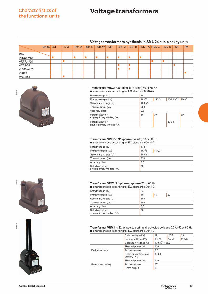
67AMTED398078EN.indd
Characteristics of the functional units
Voltage transformers61
046N
PE
5564
861
045N
Voltage transformers synthesis in SM6-24 cubicles (by unit)Units CM CVM DM1-A DM1-D DM1-W DM2 GBC-A GBC-B DMVL-A DMV-A DMV-D CM2 TM
VTsVRQ2-n/S1 b b b b b b b b
VRFR-n/S1 b b b
VRC2/S1 b b b
VRM3-n/S2 b b
VCT24 b
VRC1/S1 b
Transformer VRQ2-n/S1 (phase-to-earth) 50 or 60 Hzcharacteristics according to IEC standard 60044-2.
Rated voltage (kV) 24Primary voltage (kV) 10/3 15/3 15-20/3 20/3Secondary voltage (V) 100/3Thermal power (VA) 250Accuracy class 0.5Rated output forsingle primary winding (VA)
30 30 30
Rated output fordouble primary winding (VA)
30-50
Transformer VRFR-n/S1 (phase-to-earth) 50 or 60 Hzcharacteristics according to IEC standard 60044-2.
Rated voltage (kV) 17.5Primary voltage (kV) 10/3 15/3Secondary voltage (V) 100/3Thermal power (VA) 250Accuracy class 0.5Rated output forsingle primary winding (VA)
30
Transformer VRC2/S1 (phase-to-phase) 50 or 60 Hzcharacteristics according to IEC standard 60044-2.
Rated voltage (kV) 24Primary voltage (kV) 10 15 20Secondary voltage (V) 100Thermal power (VA) 500Accuracy class 0.5Rated output forsingle primary winding (VA)
50
Transformer VRM3-n/S2 (phase-to-earth and protected by fuses 0.3 A) 50 or 60 Hzcharacteristics according to IEC standard 60044-2.
Rated voltage (kV) 12 17.5 24Primary voltage (kV) 10/3 15/3 20/3Secondary voltage (V) 100/3 - 100/3Thermal power (VA) 200
First secondary Accuracy class 0.5Rated output for single primary (VA)
30-50
Thermal power (VA) 100Second secondary Accuracy class 3P
Rated output 50
b
b
b
b
68 AMTED398078EN.indd
Characteristics of the functional units
Voltage transformers
Transformer VRC1/S1 (phase-to-phase) 50 or 60 Hzcharacteristics according to IEC standard 60044-2.
Rated voltage (kV) 7.2Primary voltage (kV) 3.3 5 5.5 6 6.6Secondary voltage (V) 110 100 110 100 110Thermal power (VA) 300Accuracy class 0.5Rated output forsingle primary winding (VA)
100
Transformer VCT24 (phase-to-phase) 50 or 60 HzRated voltage (kV) 24Primary voltage (kV) 10 15 20Secondary voltage (V) 220Output (VA) 2500 2500 2500
4000 4000
Note: the above mentioned voltage transformers are grounded neutral. For other characteristics, please consult us.
Surge arrester
For units IM500, DM1-A, DM1-W, GAM, DMV-A*, DMVL-A
In (A) (unit) 400/630Un (kV) (unit) 7.2 10 12 17.5 24
Note: the rated voltage of the surge arrester is according to unit’s rated voltage.(*) limited up to 17.5 kV for DMV-A circuit breaker cubicles.
b
DE
5356
2D
E58
408
DE
5240
2
69AMTED398078EN.indd
Characteristics of the functional units
Protection of transformers
Fuse ratings for SM6-24 protection units such as PM, QM, QMB and QMC depend, among other things, on the following criteria:
service voltagetransformer ratingfuse technology (manufacturer)
Different types of fuses with medium loaded striker may be installed:Solefuse fuses as per standard UTE NCF 64.210Fusarc CF fuses as per IEC recommendation 60.282.1 and DIN dimensions 43.625.
For fuse-switch combination unit type QM, QMB, QMC, refer only to the selection table and reference list of fuses. For all other type of fuses, consult us.
Example: for the protection of a 400 kVA transformer at 10 kV, select either Solefuse fuses rated 43 A or Fusarc CF fuses rated 50 A.
Fuse selection tableThe color code is linked to the rated voltage of the fuse.Rating in A - no overload at –5°C < t < 40°C. Please consult us for overloads and operation over 40°C for France Transfo oil immersed type transformers.
bbb
vv
Type of fuse
Service voltage (kV)
Transformer rating (kVA) Rated voltage (kV)
25 50 100 125 160 200 250 315 400 500 630 800 1000 1250 1600 2000 2500
Solefuse (UTE NFC standards 13.100. 64.210)5.5 6.3 16 31.5 31.5 63 63 63 63 63 7.210 6.3 6.3 16 16 31.5 31.5 31.5 63 63 63 6315 6.3 6.3 16 16 16 16 16 43 43 43 43 43 6320 6.3 6.3 6.3 6.3 16 16 16 16 43 43 43 43 43 63 24
Solefuse (general case, UTE NFC standard 13.200)3.3 16 16 31.5 31.5 31.5 63 63 100 100 7.25.5 6.3 16 16 31.5 31.5 63 63 63 80 80 100 1256.6 6.3 16 16 16 31.5 31.5 43 43 63 80 100 125 12510 6.3 6.3 16 16 16 31.5 31.5 31.5 43 43 63 80 80 100 1213.8 6.3 6.3 6.3 16 16 16 16 31.5 31.5 31.5 43 63 63 80 17.515 6.3 6.3 16 16 16 16 16 31.5 31.5 31.5 43 43 63 8020 6.3 6.3 6.3 6.3 16 16 16 16 31.5 31.5 31.5 43 43 63 2422 6.3 6.3 6.3 6.3 16 16 16 16 16 31.5 31.5 31.5 43 63 63
Fusarc CF and SIBA(1) (general case for QM, QMB and QMC cubicle according to IEC 62271-105)3.3 16 25 40 50 50 80 80 100 125 125 160(1) 200(1) 7.25 10 16 31.5 40 40 50 63 80 80 125 125 160(1)
5.5 10 16 31.5 31.5 40 50 50 63 80 100 125 125 160(1) 160(1)
6 10 16 25 31.5 40 50 50 63 80 80 125 125 160(1) 160(1)
6.6 10 16 25 31.5 40 50 50 63 80 80 100 125 125 160(1)
10 6.3 10 16 20 25 31.5 40 50 50 63 80 80 100 100 125(1) 200(1) 1211 6.3 10 16 20 25 25 31.5 40 50 50 63 80 100 100 125(1) 160(1)
13.8 6.3 10 16 16 20 25 31.5 31.5 40 50 50 63 80 80 100(1) 125(1) 125(1) 17.515 6.3 10 10 16 16 20 25 31.5 40 50 50 63 80 80 100(1) 125(1) 125(1)
20 6.3 6.3 10 10 16 16 25 25 31.5 40 40 50 50 63 80 100(1) 125(1) 2422 6.3 6.3 10 10 10 16 20 25 25 31.5 40 40 50 50 80 80 100(1)
(1) = SIBA fuses
PE
5716
1
70 AMTED398078EN.indd
Characteristics of the functional units
Protection of transformers
Fuses dimensionsSolefuse (UTE standards)
DE
5356
3
ø 55
450 23
ø 6
35 35
Ur (kV)
Ir(A)
L(mm)
Ø(mm)
Weight(kg)
7.2 6.3 to 125 450 55 212 100 450 55 217.5 80 450 55 224 6.3 to 63 450 55 2
Fusarc CF
DE
5356
4
ø 6ø 45 Ø
33L 23
33
Ur (kV)
Ir(A)
L(mm)
Ø(mm)
Weight(kg)
7.2 125 292 86 3.312 6.3 292 50.5 1.2
10 292 50.5 1.216 292 50.5 1.220 292 50.5 1.225 292 57 1.531.5 292 57 1.540 292 57 1.550 292 78.5 2.863 292 78.5 2.880 292 78.5 2.8100 292 78.5 2.8
24 6.3 442 50.5 1.610 442 50.5 1.616 442 50.5 1.620 442 50.5 1.625 442 57 2.231.5 442 57 2.240 442 57 2.250 442 78.5 4.163 442 78.5 4.180 442 86 5.3
SIBA
DE
5356
4
ø 6ø 45 Ø
33L 23
33
Ur (kV)
Ir(A)
L(mm)
Ø(mm)
Weight(kg)
7.2 160 292 85 3.8200 292 85 5.4
12 125 292 67 2160 292 85 3.8200 292 85 3.8
17.5 125 442 85 5.424 100 442 85 5.4
125 442 85 5.4

71AMTED398078EN.indd
Characteristics of the functional units
Motors protection units
The current rating of fuses installed in units depends on:
motor current rating Instarting current Idfrequency of starts.
The fuses rating is calculated such that a current equal to twice the starting current does not blow the fuse within period equal to the starting time.The adjacent table indicated the ratings which should be used, based on the following assumptions:
direct on-line startupId/In y 6pf = 0.8 (P y 500 kW) or 0.9 (P > 500 kW)η = 0.9 (P y 500 kW) or 0.94 (P > 500 kW).
The indicated values are for Fusarc fuses(to DIN standard 43-625).
Example:Consider a 950 kW motor at 5 kV.
⋅ ⋅ ⋅In P
3 U η pf--------------------------------- 130 A= =
Id = 6 x In = 780 AThen select the next higher value, i.e. 790 A.For six 5-second starts per hour, select fusesrated 200 A.
Note: the same motor could not be protected for 12 starts per hour since the maximum service voltage for the required 250 A rated fuses is 3.3 kV.
bbb
bbbb
Selection of fuses for CRM unitsThe color code is linked to the rated voltage of the fuse. Starting current (A)Id/In = 6
Starting time (s) Maximum service voltage (kV)5 10 20
Number of starts per hour6 12 6 12 6 12
1410 2501290 250 250 2501140 250 250 250 250 2501030 250 250 250 250 250 250 3.3890 250 250 250 250 250 250790 200 250 250 250 250 250710 200 200 200 250 250 250640 200 200 200 200 200 250610 200 200 200 200 200 200 6.6540 160 200 200 200 200 200480 160 160 160 200 200 200440 160 160 160 160 160 200310 160 160 160 160 160 160280 125 160 160 160 160 160250 125 125 125 160 160 160240 125 125 125 125 125 160230 125 125 125 125 125 125210 100 125 125 125 125 125180 100 100 100 100 100 125170 100 100 100 100 100 100 11
Selection of fuses for CVM unitsServicevoltage (kV)
Starting current (A)
Rated operational current (continous duty) (A)
Starting time (s)5 10 30Number of starts per hour
Id = 6 x Ie Ie 3 6 3 6 3 63.3 1100 183 250 250 250
942 157 250 250 250 250 250 250785 131 200 200 200 200 200 250
6.6 628 105 160 160 160 200 200 200565 94 160 160 160 160 160 160502 84 125 160 160 160 160 160439 73 125 125 125 160 160 160377 63 100 125 100 125 125 160314 52 100 100 100 100 100 125251 42 100 100 100 100 100 100188 31 80 100 100 100 100 100126 21 50 50 63 80 80 80
Fuse selection method:if Id ≥ 6 x Ie, use Id to select the fusesif Id < 6 x Ie, use Ie to select the fuses.
Note:Fuses are 292 mm long (Fusarc fuses). Fuses are only for short circuit protection.For 250 A fuses, it is necessary to delay the opening of the contactor.
bb
72 AMTED398078EN.indd
Characteristics of the functional units
Interlocks
Switch unitsthe switch can be closed only if the earthing switch
is open and the access panel is in position.the earthing switch can be closed only if the switch
is open.the access panel for connections can be opened
only if the earthing switch is closed.the switch is locked in the open position when
the access panel is removed. The earthing switch may be operated for tests.
Circuit-breaker unitsthe disconnector(s) can be closed only if
the circuit breaker is open and the front panel is locked (interlock type 50).
the earth switch(es) can be closed only ifthe disconnector(s) is/are open.
the access panel for connections can be opened only if:
the circuit breaker is locked open,the disconnector(s) is/are open,the earth switch(es) is/are closed.
Note: it is possible to lock the disconnector(s) in the open position for no-load operations with the circuit breaker.
b
b
b
b
b
b
b
vvv
Functional interlocksThese comply with IEC recommendation 62271-200 and EDF specification HN 64-S-41.In addition to the functional interlocks, each disconnector and switch include:
built-in padlocking capacities (padlocks not supplied)four knock-outs that may be used for keylocks (supplied on request)
for mechanism locking functions.
Unit interlock
Units InterlockA1 C1 C4 A3 A4 A5 50 52 P1 P2 P3 P5
IM, IMB, IMC b b b
PM, QM, QMB, QMC, DM1-A, DM1-D, DM1-W, DM1-Z, DM1-S, DMV-A, DMV-D, DMV-S, DMVL-A
b b b b
CRM, CVM b b
NSM b b
GAM b b b
SM b b
DM2 b
bb
DE
5356
5 A1 type
O
OKey-type interlocksOutgoing unitsAim:
to prevent the closing of the earthing switch on a transformer protection unit unless the LV circuit breaker is locked in “open” or “disconnected” position.b
DE
5356
6 C1 type
S
S
to prevent the access to the transformer if the earthing switch for transformer protection has not first been closed.b
DE
5356
7 C4 type
S
SO
O
to prevent the closing of the earthing switch on a transformer protection unit unless the LV circuit breaker is locked in “open” or “disconnected” position.
to prevent the access to the transformer if the earthing switch for transformerprotection has not first been closed.
b
b
MT2
0240
EN Legend for key-type interlocks:
no key free key captive key panel or door

73AMTED398078EN.indd
Characteristics of the functional units
InterlocksD
E53
568 A3 type
O
O
Ring unitsAim:
to prevent the closing of the earthing switch of a load-side cubicle unless the line-side switch is locked “open”.b
DE
5356
9 A4 typeO O
to prevent the simultaneous closing of two switches.b
DE
5357
0 A5 typeO
OS
S
to prevent the closing of the earthing switch of the casing unit unless the downstream and the upstream switches are locked in the “open” position.b
DE
5357
1 50 typeOO
O
Prevents on-load switching of the disconnectors.
Allows off-load operation of the circuit breaker with the disconnectors open (double isolation).off-load operation of the circuit breaker with the disconnector open (single isolation).
b
bb
DE
5920
3 Type 52OO
O
Prevents on-load switching of the disconnectors.
Allows off-load operation of the contactor with the disconnectors open (double isolation).off-load operation of the contactor with the disconnector open (single isolation).
b
bb
MT2
0240
EN Legend for key-type interlocks:
no key free key captive key panel or door

74 AMTED398078EN.indd
Characteristics of the functional units
InterlocksD
E53
572 P1 type
X
O
O
X
to prevent the closing of an earthing switch if the switch of the other unit has not been locked in the “open” position.b
DE
5357
3 P2 typeX
X
OO
to prevent on-load operation of the disconnector unless the switch is locked “open”to prevent the closing of the earthing switches unless the disconnector and
the switch are locked “open”.
bb
DE
5357
4 P3 type
O X
OA X
to prevent on-load operation of the disconnector unless the switch is locked “open”to prevent the closing of the earthing switches with the unit energised, unless
the disconnector and the switch are locked “open”to allow off-load operation of the switch.
bb
b
DE
5357
5 P5 type
P
P
to prevent the closing of the earthing switch of the incoming unit unlessthe disconnector and the switch is locked “open”.b
MT2
0240
EN Legend for key-type interlocks:
no key free key captive key panel or door
75AMTED398078EN.indd
SM6-24 Contents
ConnectionsConnections selection table 76Cable-connection from below 77
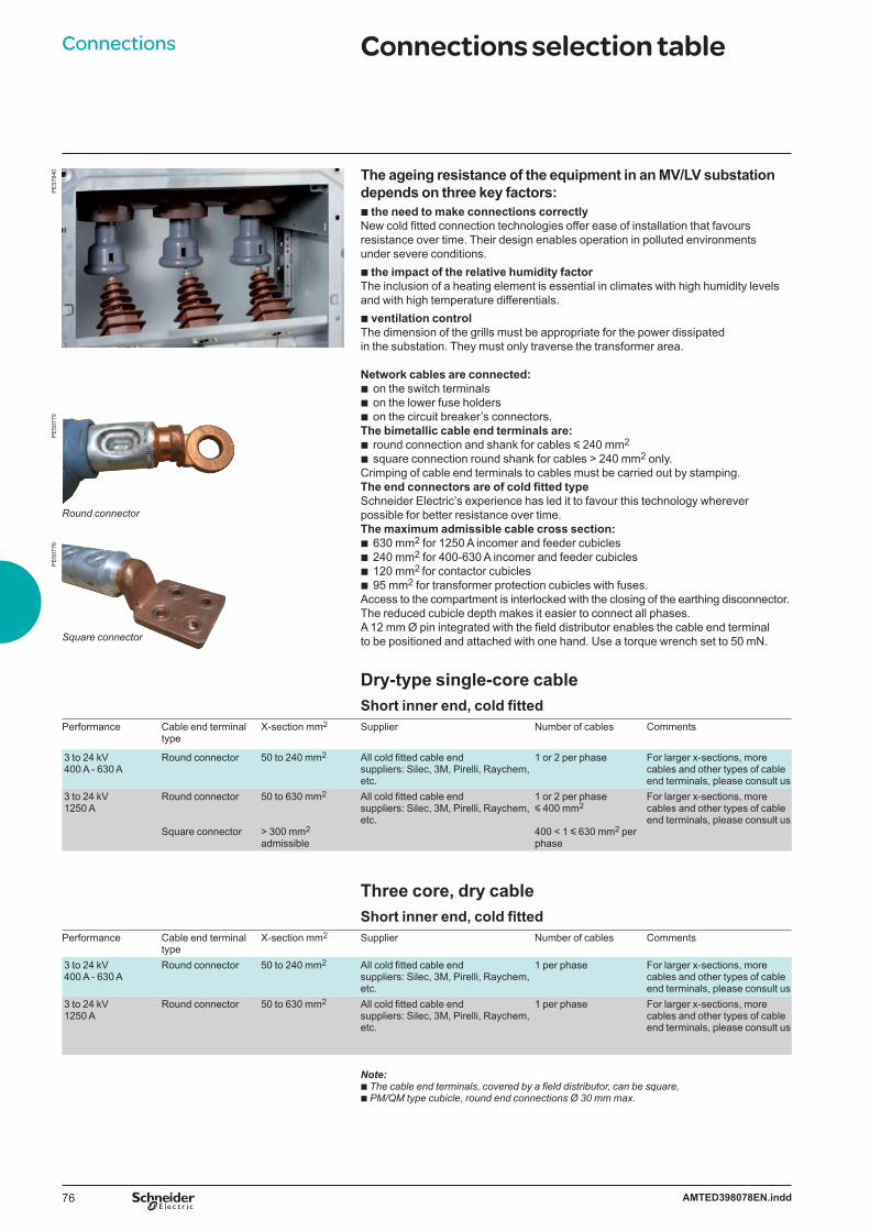
76 AMTED398078EN.indd
Connections Connections selection table
Dry-type single-core cableShort inner end, cold fitted
Performance Cable end terminal type
X-section mm2 Supplier Number of cables Comments
3 to 24 kV400 A - 630 A
Round connector 50 to 240 mm2 All cold fitted cable end suppliers: Silec, 3M, Pirelli, Raychem, etc.
1 or 2 per phase For larger x-sections, more cables and other types of cable end terminals, please consult us
3 to 24 kV 1250 A
Round connector
Square connector
50 to 630 mm2
> 300 mm2 admissible
All cold fitted cable end suppliers: Silec, 3M, Pirelli, Raychem, etc.
1 or 2 per phase y 400 mm2
400 < 1 y 630 mm2 per phase
For larger x-sections, more cables and other types of cable end terminals, please consult us
Three core, dry cableShort inner end, cold fitted
Performance Cable end terminal type
X-section mm2 Supplier Number of cables Comments
3 to 24 kV400 A - 630 A
Round connector 50 to 240 mm2 All cold fitted cable end suppliers: Silec, 3M, Pirelli, Raychem, etc.
1 per phase For larger x-sections, more cables and other types of cable end terminals, please consult us
3 to 24 kV 1250 A
Round connector 50 to 630 mm2 All cold fitted cable end suppliers: Silec, 3M, Pirelli, Raychem, etc.
1 per phase For larger x-sections, more cables and other types of cable end terminals, please consult us
Note:b The cable end terminals, covered by a field distributor, can be square,b PM/QM type cubicle, round end connections Ø 30 mm max.
PE
5077
5P
E50
776
Round connector
Square connector
The ageing resistance of the equipment in an MV/LV substation depends on three key factors:b the need to make connections correctlyNew cold fitted connection technologies offer ease of installation that favours resistance over time. Their design enables operation in polluted environments under severe conditions.b the impact of the relative humidity factor The inclusion of a heating element is essential in climates with high humidity levelsand with high temperature differentials.b ventilation control The dimension of the grills must be appropriate for the power dissipatedin the substation. They must only traverse the transformer area.
Network cables are connected:on the switch terminals on the lower fuse holders on the circuit breaker’s connectors.
The bimetallic cable end terminals are:round connection and shank for cables y 240 mm2 square connection round shank for cables > 240 mm2 only.
Crimping of cable end terminals to cables must be carried out by stamping.The end connectors are of cold fitted typeSchneider Electric’s experience has led it to favour this technology wherever possible for better resistance over time.The maximum admissible cable cross section:
630 mm2 for 1250 A incomer and feeder cubicles 240 mm2 for 400-630 A incomer and feeder cubicles120 mm2 for contactor cubicles95 mm2 for transformer protection cubicles with fuses.
Access to the compartment is interlocked with the closing of the earthing disconnector.The reduced cubicle depth makes it easier to connect all phases.A 12 mm Ø pin integrated with the field distributor enables the cable end terminal to be positioned and attached with one hand. Use a torque wrench set to 50 mN.
bbb
bb
bbbb
PE
5784
0
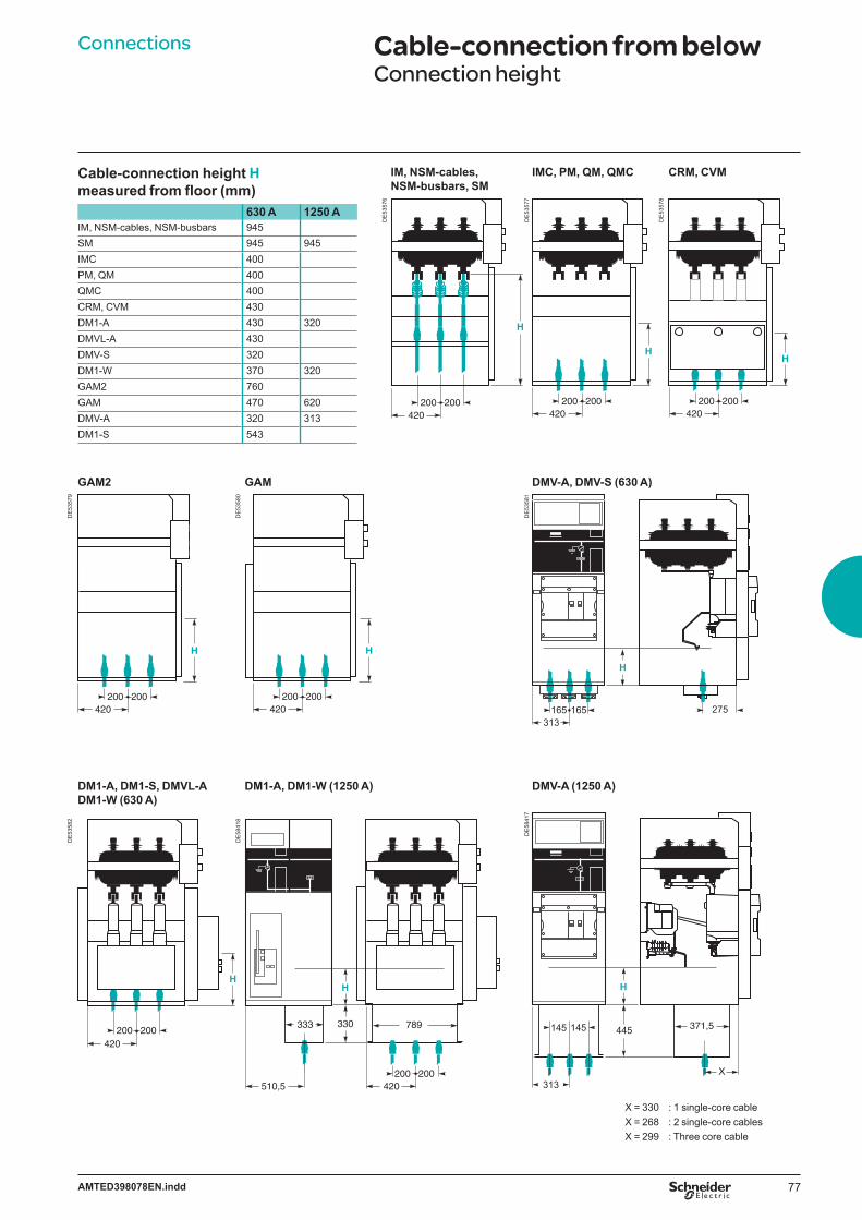
77AMTED398078EN.indd
Connections Cable-connection from belowConnection height
Cable-connection height H measured from floor (mm)
630 A 1250 AIM, NSM-cables, NSM-busbars 945SM 945 945IMC 400PM, QM 400QMC 400CRM, CVM 430DM1-A 430 320DMVL-A 430DMV-S 320DM1-W 370 320GAM2 760GAM 470 620DMV-A 320 313DM1-S 543
IM, NSM-cables, NSM-busbars, SM
IMC, PM, QM, QMC CRM, CVM
DE
5357
6
H
200420
200
DE
5357
7
H
200420
200
DE
5357
8
H
200420
200
GAM2 GAM DMV-A, DMV-S (630 A)
DE
5357
9
H
200420
200
DE
5358
0
H
200420
200
DE
5358
1
H
165313
165 275
DM1-A, DM1-S, DMVL-A DM1-W (630 A)
DM1-A, DM1-W (1250 A) DMV-A (1250 A)
DE
5358
2
200420
200
H
DE
5841
8
789330
200420
333
510,5200
H
DE
5841
7
445 371,5
H
X
145
313
145
X = 330 : 1 single-core cableX = 268 : 2 single-core cablesX = 299 : Three core cable
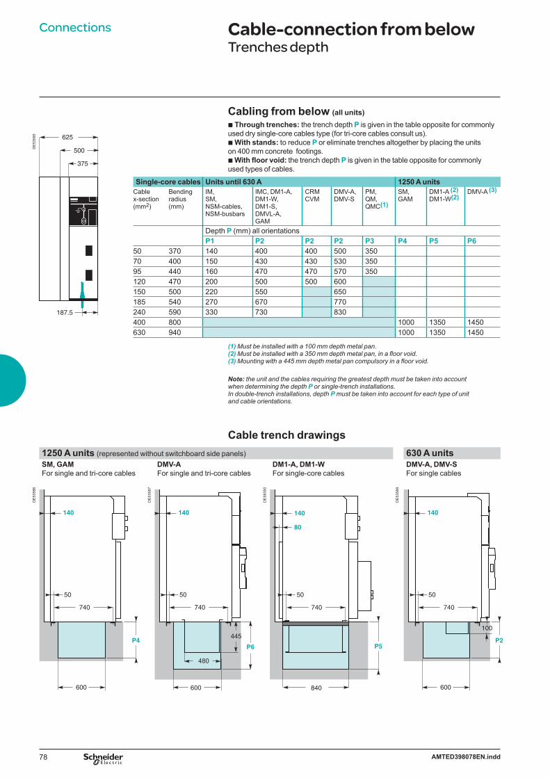
78 AMTED398078EN.indd
Connections Cable-connection from belowTrenches depth
625
500
375
187.5
DE
5358
5
Cabling from below (all units)b Through trenches: the trench depth P is given in the table opposite for commonly used dry single-core cables type (for tri-core cables consult us).b With stands: to reduce P or eliminate trenches altogether by placing the units on 400 mm concrete footings. b With floor void: the trench depth P is given in the table opposite for commonly used types of cables.
Single-core cables Units until 630 A 1250 A unitsCable x-section (mm2)
Bending radius(mm)
IM, SM, NSM-cables, NSM-busbars
IMC, DM1-A, DM1-W, DM1-S, DMVL-A, GAM
CRMCVM
DMV-A, DMV-S
PM, QM, QMC(1)
SM, GAM
DM1-A (2) DM1-W(2)
DMV-A (3)
Depth P (mm) all orientationsP1 P2 P2 P2 P3 P4 P5 P6
50 370 140 400 400 500 35070 400 150 430 430 530 35095 440 160 470 470 570 350120 470 200 500 500 600150 500 220 550 650185 540 270 670 770240 590 330 730 830400 800 1000 1350 1450630 940 1000 1350 1450
(1) Must be installed with a 100 mm depth metal pan.(2) Must be installed with a 350 mm depth metal pan, in a floor void.(3) Mounting with a 445 mm depth metal pan compulsory in a floor void.
Note: the unit and the cables requiring the greatest depth must be taken into account when determining the depth P or single-trench installations. In double-trench installations, depth P must be taken into account for each type of unit and cable orientations.
Cable trench drawings1250 A units (represented without switchboard side panels) 630 A unitsSM, GAM For single and tri-core cables
DMV-AFor single and tri-core cables
DM1-A, DM1-W For single-core cables
DMV-A, DMV-SFor single cables
DE
5358
6
600
140
P4
740
50
DE
5358
7
P6
480
600
140
740
50
445
DE
5835
0
840
740
P5
50
140
80
DE
5358
9
600
140
P2
740
50
100
79AMTED398078EN.indd
Connections Cable-connection from belowTrench diagrams example
Units represented without switchboard side panels
630 A unitsCable entry or exit through right or left side
630 A unitsRear entry or exit with conduits
630 A unitsFront entry or exit with conduits
DE
5840
9
70
600
P2
IM
IM
DM1
80
140
22
DE
5841
0
80
P1P2
140
22
DE
5841
1
140
P1P3
22
Required dimensions (mm) Note 1: for connection with conduits, the bevel (C) must correspond to the following trench dimensions: P1 = 75 mm or P2/P3 = 150 mm.Note 2: please refer to chapter “Layout examples” for a site application.
Cabling from aboveOn each 630 A unit of the range, except those including a low-voltage control cabinet and EMB compartment, the connection is made with dry-type and single-core cables.
Remark : not available for internal arc IEC 62271-200 in busbar compartment.
PE
5079
7
Height: 450 mm

80 AMTED398078EN.indd
Connections Cable-connection from belowTrench diagrams and fl oor void drawings enhanced example
For enhanced internal arc 16 kA 1 s cubicles
Installation with floor void Downwards exhaust
Installation with trench Upwards exhaust
DE
5841
2
IM
IM
DM1-A
740220
220
1060
22
DE
5841
3Ø 200
P1
100
Ø 200
Ø 200
IM
IM
DM1-A
600
1060
22
Note: to evacuate gases through the bottom, the floor void volume must be over or equal to 2 m3.
81AMTED398078EN.indd
SM6-24 Contents
InstallationDimensions and weights 82Units dimensions 83Layout examples 85
82 AMTED398078EN.indd
Installation Dimensions and weights
Type of unit Height (mm)
Width (mm)
Depth(mm)
Weight(kg)
IM,IMB 1600 (1) 375/500 940 120/130IMC 1600 (1) 500 940 200PM, QM, QMB 1600 (1) 375/500 940 130/150QMC 1600 (1) 625 940 180CRM, CVM 2050 750 940 390DM1-A, DM1-D, DM1-W, DM2, DMVL-A 1600 (1) 750 1220 400DM1-S 1600 (1) 750 1220 340DMV-A, DMV-D 1695 (1) 625 940 340DMV-S 1600 (1) 625 940 260CM 1600 (1) 375 940 190CM2 1600 (1) 500 940 210GBC-A, GBC-B 1600 750 1020 290NSM-cables, NSM-busbars 2050 750 940 260GIM 1600 125 840 30GEM (2) 1600 125 920/1060 (2) 30/35 (2)
GBM 1600 375 940 120GAM2 1600 375 940 120GAM 1600 500 1020 160SM 1600 (1) 375/500 (3) 940 120/150 (3)
TM 1600 375 940 200DM1-A, DM1-D, DM1-W, DM1-Z (1250 A) 1600 750 1220 420
Add to height:(1) 450 mm for low-voltage enclosures for control/monitoring and protection functions. To ensure uniform presentation, all units (except GIM and GEM) may be equipped with low-voltage enclosures. (2) depending on the busbar configuration in the VM6 unit, two types of extension units may be used:b to extend a VM6 DM12 or DM23 unit, use an extension unit with a depth of 1060 mmb for all other VM6 units, a depth of 920 mm is required.(3) for the 1250 A unit.
Ground preparationUnits may be installed on ordinary concrete ground, with or without trenches depending on the type and cross-section of cables.
Fixing of unitsWith each otherThe units are simply bolted together to form the MV switchboard (bolts supplied). Busbar connections are made using a torque wrench set to 28 mN.On the ground
for switchboards comprising up to three units, the four corners of the switchboard must be secured to the ground with using:
M8 bolts (not supplied) screwed into nuts set into the ground using a sealing pistol,screw rods grouted into the ground.for switchboards comprising more than three units, each unit may be fixed as
necessary.position of fixing holes b depends on the width a of units:
a (mm) 125 375 500 625 750b (mm) 95 345 470 595 720
b
vvb
b
DE
5359
5
15 15
50
740 840
12.3 x 12.3
a
b
Note: in circuit-breaker or contactor units, fixing devices are installed on the side opposite the switchgear
83AMTED398078EN.indd
Installation Units dimensions
IM, IMB, PM, QM, QMB, SM, IMC, QMC, CM, CM2 NSM-cables, NSM-busbars, CRM, CVM GBM, GAM2
DE
5359
6
450
1600
840 3070
DE
5359
7840 30
70
450
1600
DE
5359
8
840 3070
1600
GAM GIM GEM
DE
5359
9
DE
5360
0
1600
840
DE
5360
11600
920140
GBC-A, GBC-B EMB
DE
5922
9
450
84080 100
1600
DE
5841
4
503
80
1600
840 3070
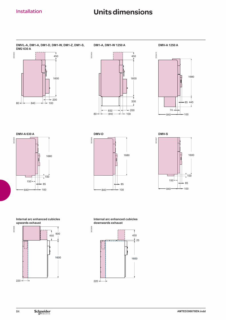
84 AMTED398078EN.indd
Installation Units dimensions
DMVL-A, DM1-A, DM1-D, DM1-W, DM1-Z, DM1-S, DM2 630 A
DM1-A, DM1-W 1250 A DMV-A 1250 A
DE
5360
3
1600
450
84080 100200
DE
5360
4
840832
330
1600
450
80 100200
DE
5841
5
1680
445
840 100
85
74
DMV-A 630 A DMV-D DMV-S
DE
5360
5
1680
840 100
100
15085
DE
5360
6
1680
840 100
85
DE
5360
71600
840 100
100
15085
Internal arc enhanced cubiclesupwards exhaust
Internal arc enhanced cubiclesdownwards exhaust
DE
5360
8
220
600450
1600
DE
5360
9
220
25
450
1600

85AMTED398078EN.indd
Installation Layout examples
Prefabricated substation (Kiosk) Conventional substation (Masonery)Internal arc cubicles 12.5 kA 1 s
PE
5716
8
DE
5841
6EN
1200 (*)
140
940
20022 (minimum)
(*) Advised access dimension
Switchboard extension exampleInternal arc cubicles 16 kA 1 s Installed against a wall for downwards and upwards exhaust
Internal arc cubicles 16 kA 1 sWith rear corridor downwards and upwards exhaust
DE
5361
1
1160
200
1200 (*)
DE
5361
2
For upwards exhaust (ceiling height u 2800 mm)
DE
5361
3
600 (min.)
600
1 600
(*) Advised access dimension

86 AMTED398078EN.indd
87AMTED398078EN.indd
SM6-24 Contents
AppendicesTrip curves for VIP 300 LL or LH relays 88Trip curves for VIP 35 relays 89Fusarc CF fuses 90Solefuse fuses 91
Modular switchboardOrder form 92
SF6 circuit breakerOrder form 99
Vacuum circuit breakerOrder form 101
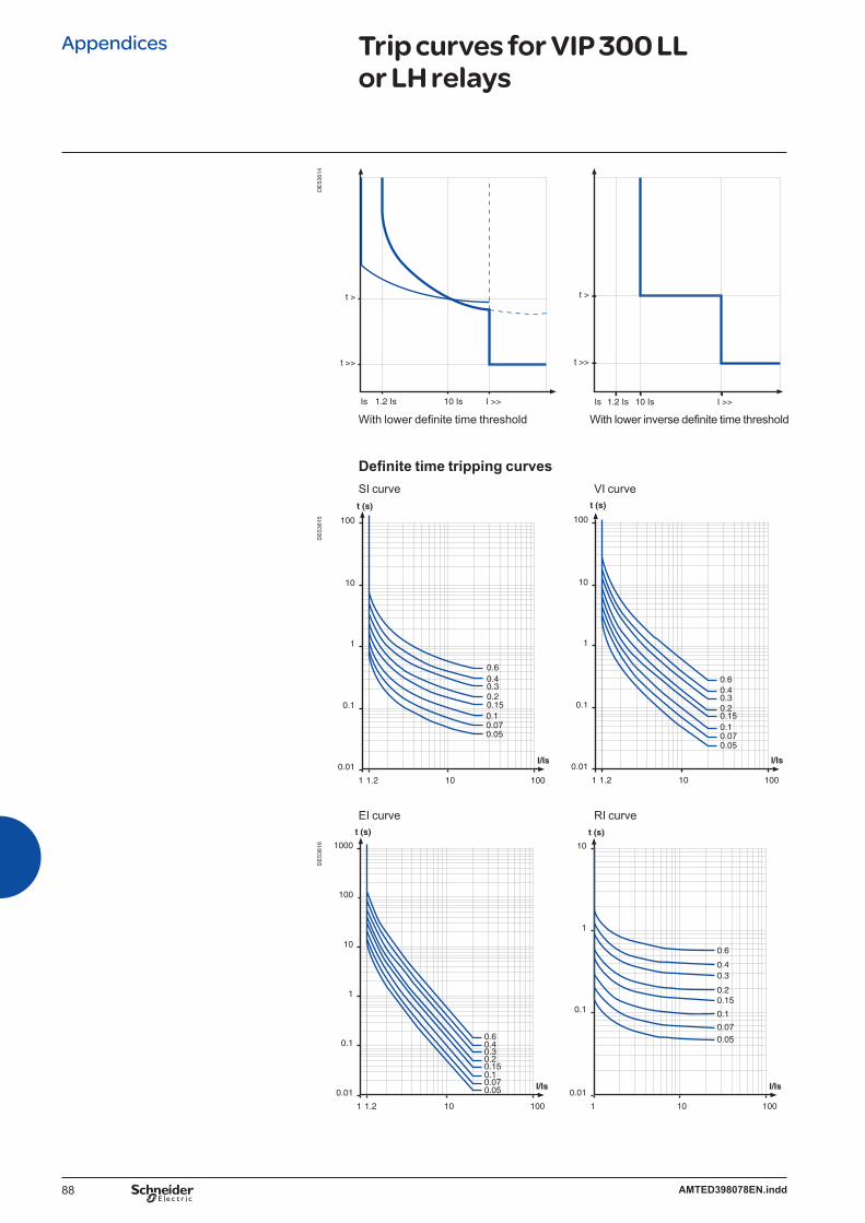
88 AMTED398078EN.indd
Appendices Trip curves for VIP 300 LL or LH relays
Is 1.2 Is 10 Is I >>
t >>
t >
Is 1.2 Is 10 Is I >>
t >>
t >
DE
5361
4
Definite time tripping curves
With lower definite time threshold With lower inverse definite time threshold
100
0.01
0.1
1
10
100
101.2
I/Is
t (s)
1
0.60.40.30.2
0.10.070.05
0.15
100
0.01
0.1
1
10
100
101.2
I/Is
t (s)
1
0.60.40.30.20.150.10.070.05
SI curve VI curve
EI curve RI curve
100
0.01
0.1
1
10
100
1000
101.2
I/Is
t (s)
1
0.60.40.30.20.150.10.070.05
100
0.01
0.1
1
10
10
I/Is
t (s)
1
0.6
0.40.3
0.20.15
0.1
0.070.05
DE
5361
5D
E53
616

89AMTED398078EN.indd
Appendices Trip curves for VIP 35 relays
Phase protection curve
The trip curve shows the time before the relay acts, to which must be added 70 ms to obtain the breaking time.
DE
5361
7EN 100
s
I/Is
10
1
0.1
0.010 1.2 5 1510 20 25 30
Type
Total breaking time
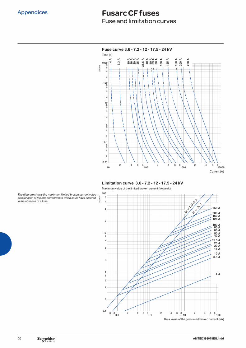
90 AMTED398078EN.indd
Appendices Fusarc CF fusesFuse and limitation curves
Fuse curve 3.6 - 7.2 - 12 - 17.5 - 24 kVTime (s)
102 4 6 8 2 4 6 8 2 4 86
100001000100
0.01
2
4
68
2
4
68
2
4
6
0.1
10
1
8
86
100
4
2
100086
4
2
10 A
6.3
A
16 A
20 A
25 A
31.5
A
50 A
63 A
80 A
100
A
160
A
200
A
250
A
4 A
125
A
40 A
Current (A)
Limitation curve 3.6 - 7.2 - 12 - 17.5 - 24 kVMaximum value of the limited broken current (kA peak)
0.12
100
2
4
1
10
101
0.1
6
8
2
4
6
8
100
2
4
8
6
4 6 86 8 2 4 6 8 2 4 6 8
50 A
250 A
200 A160 A125 A
4 A
100 A
63 A80 A
40 A
16 A20 A
6.3 A
25 A
10 A
31.5 A
Is =
Ik 2
Ia =
1.8 Ik
2
The diagram shows the maximum limited broken current value as a function of the rms current value which could have occured in the absence of a fuse.
DE
5361
8D
E53
619
Rms value of the presumed broken current (kA)

91AMTED398078EN.indd
Appendices Solefuse fuses Fuse and limitation curves
Fuse curve 7.2 - 12 - 17.5 - 24 kVTime (s)
Current (A)
Limitation curve 7.2 - 12 - 17.5 - 24 kVMaximum value of the limited broken current (kA peak)
The diagram shows the maximum limited broken current value as a function of the rms current value which could have occured in the absence of a fuse.
102 4 6 8
1002 4 6 8
10002 4 6 8
10000
1000864
2
100864
2
10864
2
1864
2
0.1864
2
0.01
6.3
A
10 A
20 A
25
A
16 A
31.5
A
43 A
63
A
80 A
100
A
125
A
6 84 62 842 84 620.1
0.1
1 10 100
10
8
6
4
2
8
6
4
2
8
6
4
2
1
100
125 A100 A80 A63 A
43 A31.5 A
10 A16 A20 A25 A
6.3 A
Is =
Ik 2
Ia =
1.8 Ik
2
DE
5362
0D
E53
621
Rms value of the presumed broken current (kA)

92 AMTED398078EN.indd
Modular switchboard Order formSM6-24Connection to the network
Basic cubicle Quantity
Rated voltage Ur (kV)
Service voltage (kV)
Short-circuit current Isc (kA)
Rated current Ir (A) Type of cubicle
SM 375 IM 375 IMB 375 IMB 375 without E/S SM 500 IM 500 IMC 500
Position number in the switchboard (from left to right) Direction of lower busbars for IMB
Left (impossible as first cubicle of switchboard) Right
OptionsReplacement of CIT by CI1 CI2
Electrical driving motorization 24 Vdc 110 Vdc 120/127 Vac (50 Hz) 32 Vdc 120-125 Vdc 220/230 Vac (50 Hz) 48 Vdc 137 Vdc 120/127 Vac (60 Hz) 60 Vdc 220 Vdc 220/230 Vac (60 Hz)
Remote control signalling2 lights 2 lights and 2 PB 2 lights and 2 PB + 1 switch
Voltage of the lights (must be the same than electrical driving mechanism)24 V 48 V 110/125 V 220 V
Signalling contact 1 C on SW and 1 O & 1 C on ES (not applicable on SM cubicle) 2 O & 2 C on SW 2 O & 3 C on SW and 1 O & 1 C on ES
Roof configuration (A, B or C only one choice possible)A - Top incomer (cable maxi 240 mm2 with voltage indicator)
Single core 2 x single core B - Low voltage control cabinet (h = 450 mm) With unpunched door C - Wiring duct
Cable connection by the bottom (not applicable on IMB, cable maxi 240 mm2)Three core Single core 2 x single core
Heating element Interlocking (with key) Ronis Profalux
For all cubicle (except SM) A4 A3 SM6-SM6 P1 SM6-SM6 Localisation of 2nd lock for A3 On switch On earthing switch Localisation of 2nd lock for A4 Cubicle no. SM cubicle only P2 SM6-SM6 P3 SM6-SM6
Surge arresters for IM 500 7.2 kV 10 kV 12 kV 17.5 kV 24 kV
Operation counter CTs for IMC (quantity) 1 2 3 Replacement of 630 A upper busbar by 1250 A Internal arc version 16 kA 1 s (not possible with “top incomer” option) Control and monitoring (48 Vdc electrical motorization compulsory)
Cubicle With relay Without relay Communication protocol
Modbus IEC DNP
Modem type RS232 RS485 Not for DNP PSTN GSM FSK
3 core balance current transformers Flair fault indicator
21D 21DT 22D 23D 23D zero sequence Digital ammeter (not applicable for IMB) Visibility of main contacts Pressure indicator device
Analogic manometer without visibility of main contacts Analogic manometer with visibility of main contacts Pressure switch
Upper field distributor for severe conditions (only for 630 A)
Only one of the boxes (ticked X or filled bythe needed value) have to be considered between each horizontal line. Blue box X corresponds to none priced functions.
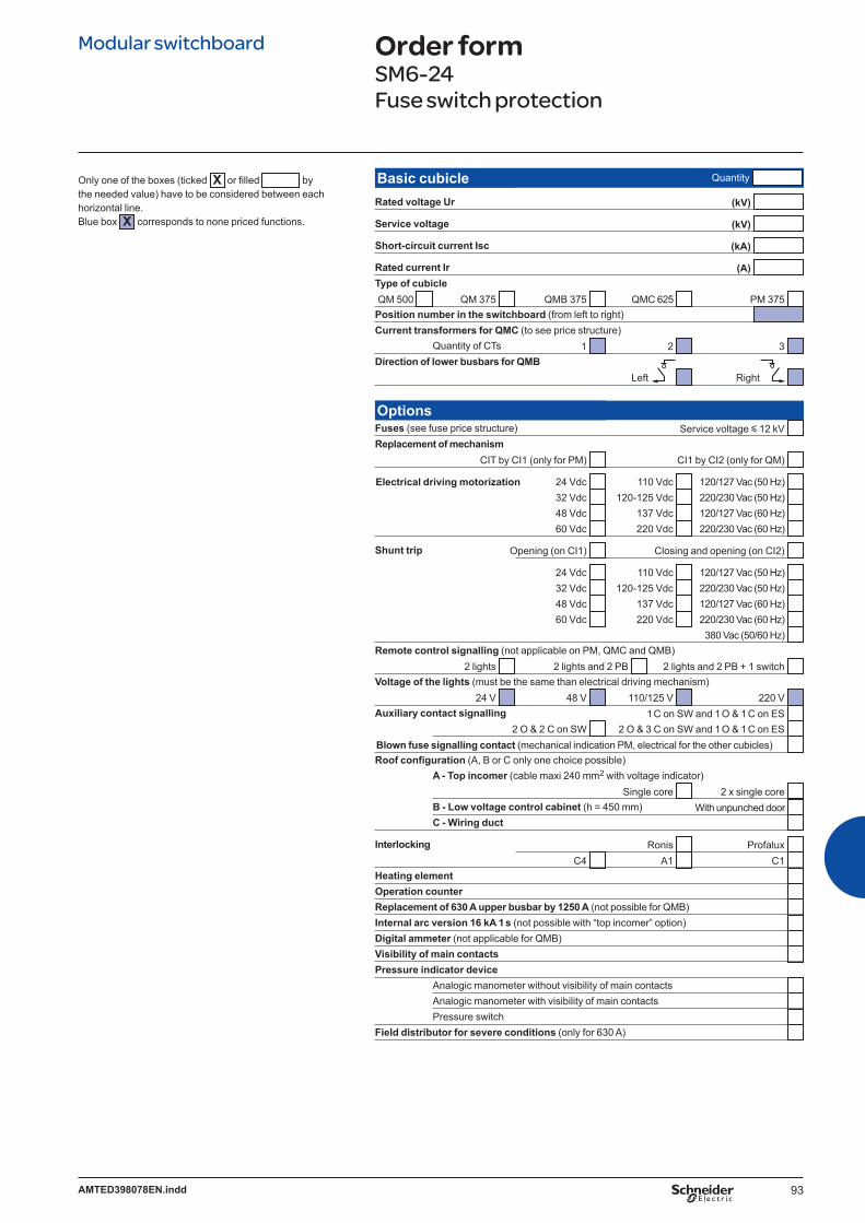
93AMTED398078EN.indd
Modular switchboard Order formSM6-24Fuse switch protection
Basic cubicle Quantity
Rated voltage Ur (kV)
Service voltage (kV)
Short-circuit current Isc (kA)
Rated current Ir (A) Type of cubicleQM 500 QM 375 QMB 375 QMC 625 PM 375
Position number in the switchboard (from left to right) Current transformers for QMC (to see price structure)
Quantity of CTs 1 2 3 Direction of lower busbars for QMB
Left Right
OptionsFuses (see fuse price structure) Service voltage y 12 kV Replacement of mechanism
CIT by CI1 (only for PM) CI1 by CI2 (only for QM)
Electrical driving motorization 24 Vdc 110 Vdc 120/127 Vac (50 Hz) 32 Vdc 120-125 Vdc 220/230 Vac (50 Hz) 48 Vdc 137 Vdc 120/127 Vac (60 Hz) 60 Vdc 220 Vdc 220/230 Vac (60 Hz)
Shunt trip Opening (on CI1) Closing and opening (on CI2)
24 Vdc 110 Vdc 120/127 Vac (50 Hz) 32 Vdc 120-125 Vdc 220/230 Vac (50 Hz) 48 Vdc 137 Vdc 120/127 Vac (60 Hz) 60 Vdc 220 Vdc 220/230 Vac (60 Hz)
380 Vac (50/60 Hz) Remote control signalling (not applicable on PM, QMC and QMB)
2 lights 2 lights and 2 PB 2 lights and 2 PB + 1 switch Voltage of the lights (must be the same than electrical driving mechanism)
24 V 48 V 110/125 V 220 V Auxiliary contact signalling 1 C on SW and 1 O & 1 C on ES
2 O & 2 C on SW 2 O & 3 C on SW and 1 O & 1 C on ES Blown fuse signalling contact (mechanical indication PM, electrical for the other cubicles) Roof configuration (A, B or C only one choice possible)
A - Top incomer (cable maxi 240 mm2 with voltage indicator)Single core 2 x single core
B - Low voltage control cabinet (h = 450 mm) With unpunched door C - Wiring duct
Interlocking Ronis Profalux C4 A1 C1
Heating element Operation counter Replacement of 630 A upper busbar by 1250 A (not possible for QMB) Internal arc version 16 kA 1 s (not possible with “top incomer” option) Digital ammeter (not applicable for QMB) Visibility of main contacts Pressure indicator device
Analogic manometer without visibility of main contacts Analogic manometer with visibility of main contacts Pressure switch
Field distributor for severe conditions (only for 630 A)
Only one of the boxes (ticked X or filled bythe needed value) have to be considered between each horizontal line. Blue box X corresponds to none priced functions.
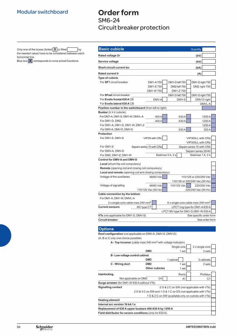
94 AMTED398078EN.indd
Modular switchboard Order formSM6-24Circuit breaker protection
Only one of the boxes (ticked X or filled bythe needed value) have to be considered between each horizontal line. Blue box X corresponds to none priced functions.
Basic cubicle Quantity
Rated voltage Ur (kV)
Service voltage (kV)
Short-circuit current Isc (kA)
Rated current Ir (A) Type of cubicle For SF1 circuit breaker DM1-A 750 DM1-D left 750 DM1-D right 750
DM1-S 750 DM2 left 750 DM2 right 750 DM1-W 750 DM1-Z 750
For SFset circuit breaker DM1-D left 750 DM1-D right 750 For Evolis frontal 630 A CB DMV-A DMV-S DMV-D right For Evolis lateral 630 A CB DMVL-A Position number in the switchboard (from left to right) Busbar (Ir u Ir cubicle) For DM1-A, DM1-S, DM1-W, DMVL-A 400 A 630 A 1250 A For DM1-D, DM2 400 A 630 A 1250 A For DM1-A, DM1-D, DM1-W, DM1-Z 1250 A For DMV-A, DMV-D, DMV-S 630 A 250 A Protection For DM1-S, DMV-S VIP35 with CRc VIP300LL with CRa VIP300LL with CRb For DM1-S Sepam series 10 with CRa Sepam series 10 with CRb For DMV-A, DMV-D Sepam series 20/40 For DM2, DM1-Z, DM1-W Statimax 5 A, 2 s Statimax 1 A, 2 s Control for DMV-A and DMV-D Local (shunt trip coil compulsory) Remote (opening coil and closing coil compulsory) Local and remote (opening coil and closing compulsory) Voltage of the auxiliaries 48/60 Vdc 110/125 or 220/250 Vdc
110/130 or 220/240 Vac (50 Hz) Voltage of signalling 48/60 Vdc 110/125 Vdc 220/250 Vdc
110/130 Vac (50 Hz) 220/240 Vac (50 Hz) Cable connection by the bottom For DM1-A, DM1-W, DMVL-A
3 x single core cable maxi 240 mm2 6 x single core cable maxi 240 mm2 Current sensors MV type CT LPCT ring type for DM1-A 630 A
LPCT MV type for DM1-D,DM1-W 630 A VTs (not applicable for DM1-S, DMV-S) See specific order formCircuit breaker See order form
OptionsRoof configuration (not applicable on DMV-A, DMV-S, DMV-D) (A, B or C only one choice possible)
A - Top incomer (cable maxi 240 mm2 with voltage indicator)Single core 2 x single core
DM2 1 set 2 sets B - Low voltage control cabinet
DM2 1 cabinet 2 cabinets C - Wiring duct DM2 1 set 2 sets
Other cubicles 1 set
Interlocking Ronis Profalux Not applicable on DM2 C4 A1 C1
Surge arrester (for DM1-W 630 A without VTs) Signalling contact 2 O & 2 C on SW (not applicable with VTs)
2 O & 3 C on SW and 1 O & 1 C on ES (not applicable with VTs) 1 O & 2 C on SW (available only on cubicle with VTs)
Heating element Internal arc version 16 kA 1 s Replacement of 630 A upper busbars 400-630 A by 1250 A Field distributor for severe conditions (only for 630 A)
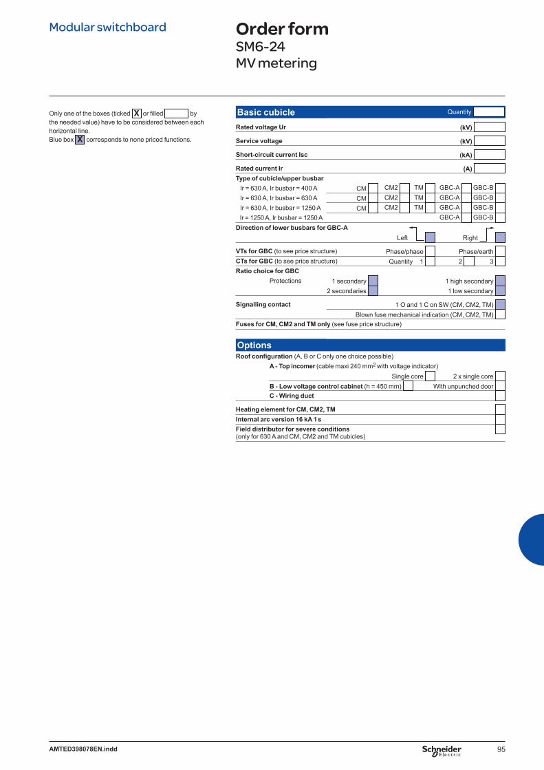
95AMTED398078EN.indd
Modular switchboard Order formSM6-24MV metering
Only one of the boxes (ticked X or filled bythe needed value) have to be considered between each horizontal line. Blue box X corresponds to none priced functions.
Basic cubicle Quantity
Rated voltage Ur (kV)
Service voltage (kV)
Short-circuit current Isc (kA)
Rated current Ir (A) Type of cubicle/upper busbar Ir = 630 A, Ir busbar = 400 A CM CM2 TM GBC-A GBC-B Ir = 630 A, Ir busbar = 630 A CM CM2 TM GBC-A GBC-B Ir = 630 A, Ir busbar = 1250 A CM CM2 TM GBC-A GBC-B Ir = 1250 A, Ir busbar = 1250 A GBC-A GBC-B Direction of lower busbars for GBC-A
Left Right
VTs for GBC (to see price structure) Phase/phase Phase/earth CTs for GBC (to see price structure) Quantity 1 2 3 Ratio choice for GBC
Protections 1 secondary 1 high secondary 2 secondaries 1 low secondary
Signalling contact 1 O and 1 C on SW (CM, CM2, TM) Blown fuse mechanical indication (CM, CM2, TM)
Fuses for CM, CM2 and TM only (see fuse price structure)
OptionsRoof configuration (A, B or C only one choice possible)
A - Top incomer (cable maxi 240 mm2 with voltage indicator)Single core 2 x single core
B - Low voltage control cabinet (h = 450 mm) With unpunched door C - Wiring duct
Heating element for CM, CM2, TM Internal arc version 16 kA 1 s Field distributor for severe conditions (only for 630 A and CM, CM2 and TM cubicles)

96 AMTED398078EN.indd
Modular switchboard Order formSM6-24Casing
Only one of the boxes (ticked X or filled bythe needed value) have to be considered between each horizontal line. Blue box X corresponds to none priced functions.
Basic cubicle Quantity
Rated voltage Ur (kV)
Service voltage (kV)
Short-circuit current Isc (kA)
Rated current Ir (A) Type of cubicle/upper busbar Ir = 630 A, Ir busbar = 400 A GAM 500 GAM2 375 GBM 375 Ir = 630 A, Ir busbar = 630 A GAM 500 GAM2 375 GBM 375 Ir = 1250 A, Ir busbar = 1250 A GAM 500 GBM 375
Position number in the switchboard (from left to right) Direction of lower busbars for GBM
Left (impossible on the first cubicle of the switchboard) Right
OptionsRoof configuration (A, B or C only one choice possible)
A - Top incomer (cable maxi 240 mm2 with voltage indicator) Single core 2 x single core
B - Low voltage control cabinet (h = 450 mm) With unpunched door C - Wiring duct
Wiring duct for GBM
ES auxiliary contact (only on GAM 500) 1 O and 1 C Surge arresters for GAM 500, 630 A
7.2 kV 10 kV 12 kV 17.5 kV 24 kV
Interlocking on GAM 500 Ronis Profalux A3 SM6-SM6 P5 SM6-SM6
Localisation of 2nd lock for P5 Cubicle no.
Heating element (on GAM 500 630 A and on GAM2) Internal arc version 16 kA 1 s Flair fault indicator
21D 22DV 23DV 23DV zero sequence Digital ammeter (not applicable for GBM)

97AMTED398078EN.indd
Modular switchboard Order formSM6-24Change Over
Only one of the boxes (ticked X or filled bythe needed value) have to be considered between each horizontal line. Blue box X corresponds to none priced functions.
Basic cubicle Quantity
Rated voltage Ur (kV)
Service voltage (kV)
Short-circuit current Isc (kA)
Rated current Ir (A) Type of cubicle/upper busbar Ir = 630 A, Ir busbar = 400 A NSM busbar NSM cable Ir = 630 A, Ir busbar = 630 A NSM busbar NSM cable Ir = 630 A, Ir busbar = 1250 A NSM cable
Position in the switchboard (from left to right) Incoming bottom busbar for NSM busbar
Left Right Cable connection by the bottom (cable maxi 240 mm2) for NSM cable
Three core on both Single core on both 2 x single core on both 3 x single core on one cubicle and 2 x three core on the other one
Stand by source Generator Utility With paralleling Without paralleling
OptionsSignalling contact 1 C on SW and 1 O & 1C on ES
Operation counter
Interlocking SM6-SM6 Ronis Profalux 1 x P1 Right cubicle Left cubicle 2 x P1 Right and left cubicle 1 x A3 Right cubicle Left cubicle
On switch On earthing switch 2 x A3 Right cubicle On switch On earthing switch
Left cubicle On switch On earthing switch
2 heating elements (set)
Telecontrol (only with utility stand by source) Communication protocol
Modbus IEC DNP
Modem type RS232 RS485 Not for DNP PSTN GSM FSK
Field distributor for severe conditions (only for 630 A busbar)
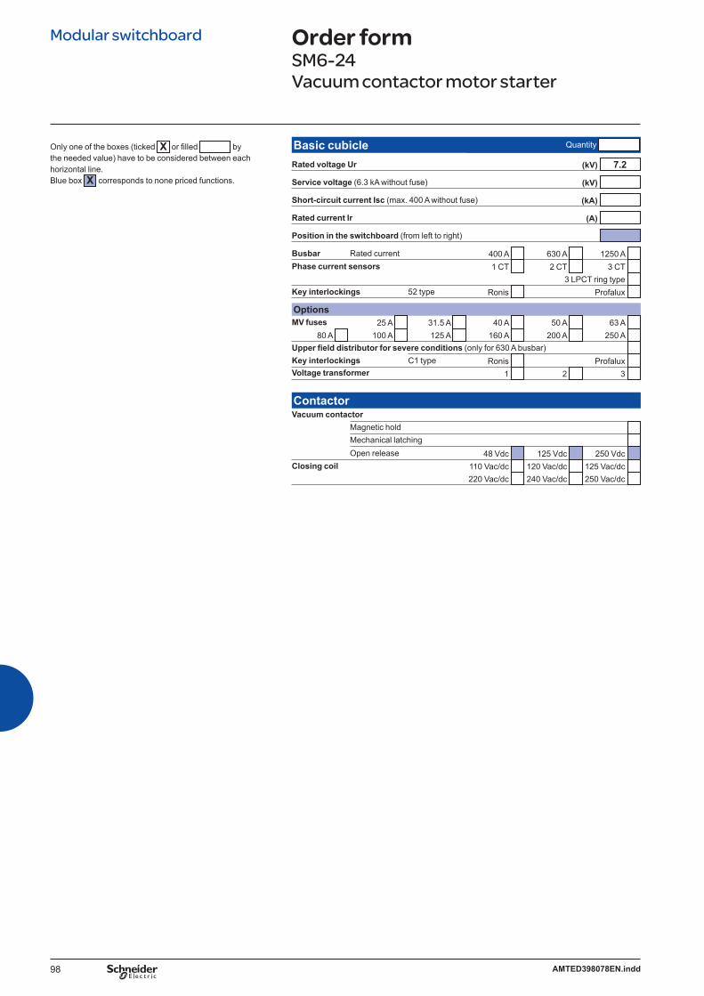
98 AMTED398078EN.indd
Modular switchboard Order formSM6-24Vacuum contactor motor starter
Only one of the boxes (ticked X or filled bythe needed value) have to be considered between each horizontal line. Blue box X corresponds to none priced functions.
Basic cubicle Quantity
Rated voltage Ur (kV) 7.2
Service voltage (6.3 kA without fuse) (kV)
Short-circuit current Isc (max. 400 A without fuse) (kA)
Rated current Ir (A)
Position in the switchboard (from left to right)
Busbar Rated current 400 A 630 A 1250 A Phase current sensors 1 CT 2 CT 3 CT
3 LPCT ring type Key interlockings 52 type Ronis Profalux
OptionsMV fuses 25 A 31.5 A 40 A 50 A 63 A
80 A 100 A 125 A 160 A 200 A 250 A Upper field distributor for severe conditions (only for 630 A busbar) Key interlockings C1 type Ronis Profalux Voltage transformer 1 2 3
ContactorVacuum contactor
Magnetic hold Mechanical latching Open release 48 Vdc 125 Vdc 250 Vdc
Closing coil 110 Vac/dc 120 Vac/dc 125 Vac/dc 220 Vac/dc 240 Vac/dc 250 Vac/dc

99AMTED398078EN.indd
Only one of the boxes (ticked X or filled bythe needed value) have to be considered between each horizontal line. Blue box X corresponds to none priced functions.
SF6 circuit breaker Order formSF1 lateral disconnectable or withdrawablefor SM6-24
Basic circuit breaker Quantity
Rated voltage Ur (kV)
Service voltage (kV)
Impulse voltage Up (kVbil)
Short-circuit current Isc (kA)
Rated current Ir (A)
Frequency 50 Hz 60 Hz
Mechanism position Disconnectable A1 B1 Withdrawable B1
Colour for push buttons and indicatorsPush buttons open/close: Red/black Indicator open/close: Black/white Operating mechanism charged/discharged: White/yellow
Circuit breaker options1st opening release (see possible choices combination table below)
Shunt opening release YO124 Vdc 60 Vdc 220 Vdc 220 Vac (50 Hz) 30 Vdc 110 Vdc 48 Vac (50 Hz) 120 Vac (60 Hz) 48 Vdc 125 Vdc 110 Vac (50 Hz) 240 Vac (60 Hz)
Undervoltage release YM24 Vdc 60 Vdc 220 Vdc 220 Vac (50 Hz) 30 Vdc 110 Vdc 48 Vac (50 Hz) 120 Vac (60 Hz) 48 Vdc 125 Vdc 110 Vac (50 Hz) 240 Vac (60 Hz)
Mitop Without contact With contact
2nd opening release (see possible choices combination table below)Shunt opening release YO2
24 Vdc 60 Vdc 220 Vdc 220 Vac (50 Hz) 30 Vdc 110 Vdc 48 Vac (50 Hz) 120 Vac (60 Hz) 48 Vdc 125 Vdc 110 Vac (50 Hz) 240 Vac (60 Hz)
Undervoltage release YM24 Vdc 60 Vdc 220 Vdc 220 Vac (50 Hz) 30 Vdc 110 Vdc 48 Vac (50 Hz) 120 Vac (60 Hz) 48 Vdc 125 Vdc 110 Vac (50 Hz) 240 Vac (60 Hz)
Mitop Without contact With contact
Remote controlElectrical motor M 24…32 Vdc 110…127 Vdc/ac
48…60 Vdc/ac 220…250 Vdc/ac Shunt closing release YF
24 Vdc 60 Vdc 220 Vdc 220 Vac (50 Hz) 30 Vdc 110 Vdc 48 Vac (50 Hz) 120 Vac (60 Hz) 48 Vdc 125 Vdc 110 Vac (50 Hz) 240 Vac (60 Hz)
Leaflets language French English
Different releases combinationsShunt opening releases YO1/YO2 1 2 1 1Undervoltage release YM 1 1 1Mitop 1 1 1
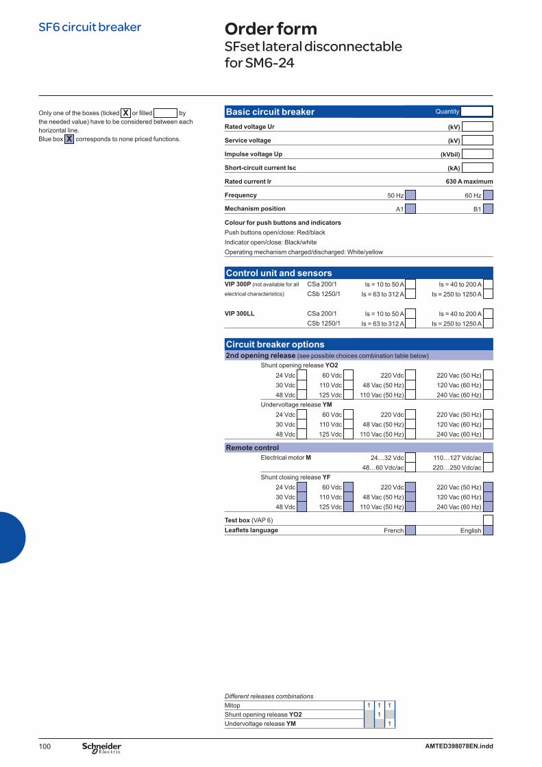
100 AMTED398078EN.indd
Only one of the boxes (ticked X or filled bythe needed value) have to be considered between each horizontal line. Blue box X corresponds to none priced functions.
SF6 circuit breaker Order formSFset lateral disconnectablefor SM6-24
Basic circuit breaker Quantity
Rated voltage Ur (kV)
Service voltage (kV)
Impulse voltage Up (kVbil)
Short-circuit current Isc (kA)
Rated current Ir 630 A maximum
Frequency 50 Hz 60 Hz
Mechanism position A1 B1
Colour for push buttons and indicatorsPush buttons open/close: Red/black Indicator open/close: Black/white Operating mechanism charged/discharged: White/yellow
Control unit and sensorsVIP 300P (not available for all CSa 200/1 Is = 10 to 50 A Is = 40 to 200 A electrical characteristics) CSb 1250/1 Is = 63 to 312 A Is = 250 to 1250 A
VIP 300LL CSa 200/1 Is = 10 to 50 A Is = 40 to 200 A CSb 1250/1 Is = 63 to 312 A Is = 250 to 1250 A
Circuit breaker options2nd opening release (see possible choices combination table below)
Shunt opening release YO224 Vdc 60 Vdc 220 Vdc 220 Vac (50 Hz) 30 Vdc 110 Vdc 48 Vac (50 Hz) 120 Vac (60 Hz) 48 Vdc 125 Vdc 110 Vac (50 Hz) 240 Vac (60 Hz)
Undervoltage release YM24 Vdc 60 Vdc 220 Vdc 220 Vac (50 Hz) 30 Vdc 110 Vdc 48 Vac (50 Hz) 120 Vac (60 Hz) 48 Vdc 125 Vdc 110 Vac (50 Hz) 240 Vac (60 Hz)
Remote controlElectrical motor M 24…32 Vdc 110…127 Vdc/ac
48…60 Vdc/ac 220…250 Vdc/ac Shunt closing release YF
24 Vdc 60 Vdc 220 Vdc 220 Vac (50 Hz) 30 Vdc 110 Vdc 48 Vac (50 Hz) 120 Vac (60 Hz) 48 Vdc 125 Vdc 110 Vac (50 Hz) 240 Vac (60 Hz)
Test box (VAP 6) Leaflets language French English
Different releases combinationsMitop 1 1 1Shunt opening release YO2 1Undervoltage release YM 1

101AMTED398078EN.indd
Vacuum circuit breaker Order formEvolis frontal fi xed version for SM6-24up to 17.5 kV
Basic fixed circuit breaker Quantity
Rated voltage Ur (kV) 12 17.5
Service voltage (kV)
Short-circuit current Isc 25 kA
Rated normal current Ir (A) 630 1250
Phase distance 185 mm
Circuit breaker optionsOpening release (see possible choices in combination table below)
Shunt opening release MX24 Vac 24…30 Vdc 100…130 Vdc/ac 48 Vac 48…60 Vdc 200…250 Vdc/ac
Low energy release Mitop 1 AC fault signalling SDE and reset 200...250 Vac are included
Remote control (operation counter already included)Electrical motor MCH
24…30 Vdc 100…125 Vdc 200…250 Vdc 48…60 Vdc/ac 100…130 Vac 200…240 Vac
Shunt closing release XF24 Vac 24…30 Vdc 100…130 Vdc/ac 48 Vac 48…60 Vdc 200…250 Vdc/ac
Operation counter CDM Additional auxiliary contacts OF (4 AC) 1 2 Ready to close contact PF (1 AC) Locking of the circuit breaker in the open position
By padlock or by locks and keys Profalux Ronis If locks 1 lock 2 identical locks 2 different locks
Disabling of O/C circuit breaker push buttons
Only one of the boxes (ticked X or filled bythe needed value) have to be considered between each horizontal line. Blue box X corresponds to none priced functions.
Different releases combinationsShunt opening release MX 1 1Mitop 1 1

102 AMTED398078EN.indd
Vacuum circuit breaker Order formEvolis lateral disconnectable version for SM6-24 at 24 kV
Basic circuit breaker Quantity
Rated voltage Ur 24 (kV)
Service voltage (kV)
Impulse voltage Up (kVbil)
Rated normal current Ir 630 A maximum
Phase distance 250 mm
Mechanism position B1
Colour for push buttons and indicatorsPush buttons open/close: Red/black Indicator open/close: Black/white Operating mechanism charged/discharged: White/yellow
Circuit breaker options1st opening release (see possible choices combination table below)
Shunt opening release YO124 Vdc 110 Vdc 110 Vac (50 Hz) 48 Vdc 125-127 Vdc 220-230 Vac (50 Hz)
220 Vdc 120 Vac (60 Hz) Undervoltage release YM
24 Vdc 110 Vdc 110 Vac (50 Hz) 48 Vdc 125-127 Vdc 220-230 Vac (50 Hz)
220 Vdc 120 Vac (60 Hz)
2nd opening release (see possible choices combination table below)Shunt opening release YO2
24 Vdc 110 Vdc 110 Vac (50 Hz) 48 Vdc 125-127 Vdc 220-230 Vac (50 Hz)
220 Vdc 120 Vac (60 Hz) Undervoltage release YM
24 Vdc 110 Vdc 110 Vac (50 Hz) 48 Vdc 125-127 Vdc 220-230 Vac (50 Hz)
220 Vdc 120 Vac (60 Hz) Low energy release Mitop
Remote control (operation counter already included)Electrical motor M 24…32 Vdc 110…127 Vdc/ac
48…60 Vdc/ac 220…250 Vdc/ac Shunt closing release YF
24 Vdc 110 Vdc 110 Vac (50 Hz) 48 Vdc 125-127 Vdc 220-230 Vac (50 Hz)
220 Vdc 120 Vac (60 Hz)
Operation counter (already included if remote control supplied)
Only one of the boxes (ticked X or filled bythe needed value) have to be considered between each horizontal line. Blue box X corresponds to none priced functions.
Different releases combinations Shunt opening releases YO1 1 1 1 1Shunt opening releases YO2 1Undervoltage release YM 1 1 1Mitop 1 1 1

103AMTED398078EN.indd
Notes

104 AMTED398078EN.indd
Notes

AMTED398078EN 01-2010
AR
T.16
044
© S
chne
ider
Ele
ctric
Indu
strie
s S
AS
- A
ll rig
hts
rese
rved
As standards, specifications and designs change from time to time, please ask for confirmation of the information given in this publication.
Publishing: Schneider Electric Industries SASDesign: Schneider Electric Industries SASPrinting: Imprimerie du Pont de Claix/JPF - Made in France
This document has been printed on ecological paper
Schneider Electric Industries SAS35, rue Joseph Monier CS 30323 F - 92506 Rueil Malmaison Cedex
RCS Nanterre 954 503 439 Capital social 896 313 776 €www.schneider-electric.com