Embed Size (px)
Citation preview
MOTOTAMBURI PER NASTRI TRASPORTATORI
BEL CONVEYOR DRUM MOTORS
CATALOgO MT 02
L’innovazione è un moto spontaneo


MT 02
CATALOGO MT 02
ACCESSORI PER TRASPORTATORI A NASTRO
Il catalogo è suddiviso in capitoli, così contrassegnati:
CATALOGUE MT 02
COMPONENTS fOR bULk hANdLINGCONvEyORS
The catalog is divided into the following chapters wich are indicated as follows:
Sigla Capitolo Chapter Initials
Macroarea di riferimentoMacro-area reference
indice indexCAPITOLO SIGLA CAPITOLO CHAPTER CHAPTER INITIALS
MOTOTAMBURI PER TRASPORTATORI A NASTRO MT 10
CALCOLO e SCeLTA deI mOTOTAmburI MT 11
InfOrmAzIOnI TeCnIChe MT 12
SChede PrOdOTTO MT 13
uSO e mAnuTenzIOne MT 15
CONVEYOR DRUM MOTORS MT 10
CALCuLATIoN ANd CHoICE of dRuM MoToRS MT 11
GENERAL TECHNICAL INfoRMATIoNS MT 12
SELECTIoN CHARTS MT 13
oPERATING INSTRuCTIoNS MT 15


MOTOTAMbURI LAT
1
QUESTIONARIOQUESTIONNAIRE
MT 10
Rev. 01/16

2
QUESTIONARIOQUESTIONNAIRE
❏ Ordine ❏ richiesta d’offerta mototamburi LAT❏ Order ❏ Inquiry LAT drum motors
mototamburo tipo / drum motor type
Quantità / Quantity
diametro / diameter (mm.)
mantello /drum shell ❏ cilindrico/cylindric (d1=d2)
❏ bombato/crowned
Lunghezza / length (mm.)
Potenza / Power (kW)
Velocità del nastro / belt speed (m/sec)
Classe protezione / Protection class ❏ IP65 ❏ IP66 ❏ IP66/67
Classe ISO Class f
Tensione / Voltage (Volt)
numero delle fasi / no. Of phases ❏ trifase/three-phase ❏ monofase/single-phase
frequenza / frequency (hz)
dimensioni asse (mm.) / Shaft dimensions (mm.) d: e: f: b:
Lunghezza eL length (mm.)
Orientamento dei piani delle chiavi / direction of spanner flats
❏ verticale ❏ orizzontale ❏ vertical ❏ horizontal
Collegamento / version of connection
❏ morsettiera ❏ cavo a 90° ❏ cavo diritto ❏ cavo con angolo variabile
❏ terminal box ❏ 90° cable gland ❏ straingt cable gland ❏ variable cable gland
Lunghezza cavo /cable length (m.)
freno elettromagnetico / electromagnetic brake ❏ si/yes ❏ no/no
Antiritorno meccanico / mechanical backstop ❏ si/yes ❏ no/no
direzione del movimento libero / fre direction of rotation ❏ destra/right ❏ sinistra/left
rivestimento in gomma / rubber coating ❏ si/yes ❏ no/no
materiale del mantello / material of drumshell ❏ acciaio/mild steel ❏ inox/stainless steel
materiale dell’asse / material of shaft ❏ acciaio/mild steel ❏ inox/stainless steel
materiale del fondello / material of end caps ❏ acciaio/mild steel ❏ inox/stainless steel
❏ alluminio resistente all’acqua di mare/seawater resistant aluminium ❏ ghisa/ cast-iron
Supporti per il mototamburo / Clamping bearings for above drum motor ❏ si/yes ❏ no/no
Tamburo di rinvio / Guide drum for above drum motor ❏ si/yes ❏ no/no
Indirizzo del cliente - Customer’s address
extra (esempi): Olio specialedisegno rivestimento in gomma
extras (f.i.): quality of oildesign of rubber coating.
MT 10

MT 11
MOTOTAMbURI LAT
1
INfORMAzIONI TECNIChE PER IL CALCOLO E LA SCELTA
TEchNIcAl INfORmATIONS fOR ThE cAlcUlATION ANd chOIcE
Rev. 01/16

2
CALCOLO E SCELTA dELLE STAzIONI A RULLI NEI TRASPORTATORI A NASTROMT11
H
SCELTA DEL MOTOTAMBUROCalcolo della resistenza al moto (Carichi isolati).Per la determinazione delle resistenze al moto di trasportatori a nastro occorrono i seguenti dati di calcolo, che si basano sul metodo secondo dIn 22101.Le forze che si oppongono al movimento di un trasportatore a nastro consistono, in funzionamento stazionario, in forze di at-trito, di peso e di inerzia.Il fabbisogno di potenza del trasportatore è il prodotto di queste resistenze al moto per la velocità del nastro. Per calcolare le resistenze, queste vengono suddivise in prin-cipali, secondarie, di salita e specifiche. La somma di queste resistenze è uguale alla forza tangenziale f che il tamburo tra-smette al nastro, così:
F = 9,81 ( Fo + F1 + F2 + F3) [N]
La potenza motrice necessaria si ottiene come segue:
F•vp= __________ [Kw] 1000• t
Simboli ed unità di misura:
F = Forza di trazione necessaria sul nastro (N)
m’ n = Peso del nastro (kg/m)
m’ pr = Peso delle masse mobili del trasportatore a nastro (kg/m)
m' m1= Peso del materiale trasportato (Kg/m)
C1 = Coefficiente di attrito fra materiale trasportato e nastro.
C2 = Coefficiente di attrito fra nastro e piano di scorrimento
in lamiera (tratto superiore nastro).
L = interasse fra tamburo motore e tamburo di rinvio (m)
H = dislivello superato dal nastro (m)
v = velocità del nastro (m/s)
P = potenza del tamburo motore (kw)
t = rendimento del mototamburo (circa 0,94)
SELECTION OF DRIVECalculation of forces on conveyor belts (unit handling)For a rough estimation of the forces on conveyor the following calculation scheme is very helpful. It is based on the method of determination given in DIN 22101.The forces in opposition to the movement of a conveyor belt sys-tem are composed of friction, weight and mass forces, considering stationary duty. The required output of a conveying system is given as the product of forces and belt speed.For calculation of the forces they are subdivided into main, auxil-iary, slope, and special forces. The sum of these forces is equal to the circumferential force "F" the conveyor drum has to transmit to the belt, consequently:
F = 9,81 ( Fo + F1 + F2 + F3) [N]
The required power is calculated according to the following for-mula:
F•vP= ___________ [Kw] 1000• t
Formula symbols:
F = required force on the belt [N]
m'n = weight of the belt [kg/m]
m'pr = weight of the accelerated masses of the conveyor
equipment [kg/m ]
m'm1= weight of materials transported [kg/m]
C1 = friction coefficient between transported materials and belt.
C2= friction coefficient between belt and sliding frame (upper belt)
L = centre distance conveyor drum to guide drum [m]
H = height for rising belt [m]
v = belt speed [m/s]
P = Power of drum-motor [kW]
t = Efficiency of drum motor, [ca.0.94] [kW]
Nastro striscianteSliding conveyance
Modalità di TrasportoType of conveyance
Nastro scaricoWithout load
Nastro in pianoHorizontal transportation
Nastro in salitaSloping belt drive
Nastro con accumulo dei carichiDuty on accumulation
Nastro su rulliRolling conveyance
Fo = 0,04 ( 2 m'n + m'pr) L
Fo=1,1•m'n•L•C2
F1=0,04•m'm1•L
F1=1,1•m'm1•L•C2
F2 = m'm1•H
F2 = m'm1•H
F3 = m'm1•L•C1
F3 = m'm1•L•C1
m'm1
m'm1
L
L

3
CALCULATION ANd SELECTION Of IdLERS IN bELT CONvEyORS MT11
Larghezza nastro
Belt width B mm 500 600 650 800 1000 1200 1400 1600 1800
Per nastri standard - Gm (kg/m)For standard conveyor belts - Gm (kg/m)
17 26 28 40 56 70 85 105 120
Per nastri pesanti e profilati Gm (kg/m) For heavy and shaper belts - Gm (kg/m) 20 30 32 45 63 80 110 135 160
L [m]C
39,0
47,6
56,6
65,9
75,1
84,5
104,1
163,6
203,2
252,9
322,6
L [m]C
402,4
502,2
632,0
801,92
1001,78
1251,65
1601,59
2001,45
2501,38
3001,31
4001,25
L [m]C
5001,20
6001,17
7001,14
8001,12
9001,10
10001,09
12001,09
14001,06
16001,06
18001,05
20001,05
Tabella “B” - Table “B”
Tabella “A” - Table "A"Valori del coeff. “C” per trasportatori a nastro con grado di riempimento “phi” compreso fra 0,7 e 1,1Basis of valuation for coefficient “C” in case of conveyor drum equipment with volumetric efficiency “phi” in the range of 0,7 – 1,1.
SELECTION OF DRIVERequired power on stationary duty conditions (bulk handling).The required power of a uniformly loaded conveyor drum equip-ment with volumetric efficiencψ in the range of O.7 up lo 1.1 re-quires a circumferential power of the drum motor of the following value: P=F•v
Considering the coefficients C and Gm, given in the tables below, we are in a position to achieve an estimated calculation schema for the required power consumption: (DIN 22101).
C•f•L Qt •HP= _______ (3,6•Gm•v+Qt ) + _____ [Kw] 376 367
Formula symbols:P = power for the complete equipment [kW]. C = valuation for coefficient "C” for ball bearing, etc. (refer to table A).f = valuation for coefficient "f" considers the influence of duty conditions regarding return and carrying rollers [factor 0,025 – 0,030].L = centre distance conveyor drum to guide drum [m].Gm = Weight of the belt and the movable components of the conveyor equipment [kg/m] (refer to table B).v = belt speed [m/s).Qt = theoretical delivery in tons per hour [t/h].H = height for rising belt [m].B = belt width. [mm].
The calculation scheme given above doesn’t include the required additional power for stripping forks, sealing ledges, etc.
SCELTA DEL MOTOTAMBUROFabbisogno di potenza in funzionamento stazionario (trasporto di materiale alla rinfusa)La potenza richiesta alla periferia del tamburo motore da un tra-sportatore a nastro caricato uniformemente con grado di riempi-mento compreso fra 0,7 ed 1,1 è P=F•v
Considerando i fattori C e Gm elencati in tabella è possibile una determinazione preventiva della potenza motrice (DIN 22101)
C•f•L Qt •HP= _______ (3,6•Gm•v+Qt ) + _____ [Kw] 376 367
Simboli delle formule ed unità di misura:P = Potenza motrice per l’intero nastro (kw).C = Coefficiente “C” per cuscinetti, ecc.(vedi tabella A).f = coefficiente “f” relativo all’influenza delle condizioni di lavoro fra rulli di ritorno e rulli portanti (fattore 0,025-0,030).L = interasse fra tamburo motore e tamburo di rinvio (m)Gm = peso del nastro e delle parti mobili del trasportatore in kg/m (vedi tabella B)v = velocità del nastro (m/s)Qt = Portata teorica del nastro in tonnellate/ora (t/h)H = Dislivello superato dal nastro (m)B = larghezza nastro in mm.
Lo schema di calcolo sopra rappresentato non considera la po-tenzasupplementarerichiestadaraschianastro,bavette,ecc.

CALCOLO E SCELTA dELLE STAzIONI A RULLI NEI TRASPORTATORI A NASTROMT11
4
Tutte le dimensioni sono soggette a tolleranze di lavorazione e benché i disegni e le illustrazioni siano fedeli, non sono tuttavia impegnativi. La DUGOMRULLI si riserva di modificare i propri prodotti senza preavviso.La riproduzione anche parziale delle figure e del testo è vietata a norma del C.C. e della legge sui diritti d’autore.
All dimensions are subject to machining tolerances, and although drawings and illustrations are exact, they place the manufacturer under no obligation whatsoever.DUGOMRULLI reserves the right to modify their products at any time without notice. Even a part reproduction of present catalogue’s illustrations, and text, is forbidden.

MOTOTAMbURI LAT
INfORMAzIONI TECNIChEGENERAl TEchNIcAl INfORmATION
1
MT12
Rev. 01/16

2
MT12 INfORMAzIONI TECNIChEMOTOTAMBURI PER TRASPORTATORI A NASTRO
raffreddati ad olio. Completamente chiusi, stagni alla polvere ed agli spruzzi d’acqua con protezioni IP65/IP66 (dIn en 60529).motore interno trifase con rotore in corto circuito, riduttore pla-netario per tipo LAT60/80 ed a ingranaggio elicoidale dal tipo LAT 82 al tipo LAT 600, morsettiere in scatole pressofuse e perni per il fissaggio.
Condizioni di fornituraCi riserviamo la possibilità di modificare le potenze, i dati tecnici, le dimensioni ed i pesi indicati in catalogo senza preavviso.
I disegni non sono impegnativi.
I mototamburi devono essere installati conformemente alle no-stre istruzioni di montaggio e secondo le norme locali e nazio-nali applicabili.
LAT CONVEYOR DRUM MOTORS
oil-cooled, totally enclosed, dust-proof and hose-proof according to protecting system IP65/IP66 (dIN EN 60529) with integrated three phase squirrel cage motor, planetary gear for TM 60 / 80 and helical gear for TM 82 / 800, cast-capsuled terminal box and two shafts.
Sales conditions:We reserve the right to change ratings, data dimensions and weights without prior notice due to further development.
drawings are not binding
Equipment must be installed according to our installation instructions and applicable local and national safety regulations.

MT12
3
GENERAL TEChNICAL INfORMATIONINFORMAzIONI TECNICHE
GeneralitàI mototamburi LAT sono progettati per mettere in movimento trasportatori a nastro, fissi o mobili, per il trasporto di materiale alla rinfusa e di carichi isolati. Possono essere utilizzati anche in trasportatori senza nastro.Per la loro struttura compatta e la facilità di montaggio i moto-tamburi LAT sono utilizzati da decenni in molti tipi di applicazio-ni nel campo delle tecniche di movimentazione.
Caratteristiche strutturaliIl motore elettrico ed il riduttore sono alloggiati all’interno del mantello e costituiscono un’unità motrice chiusa ben protetta rispetto all’ambiente esterno.L’abbondante dimensionamento dei componenti garantisce una lunga vita anche in condizioni di lavoro severe. I più moderni si-stemi di lavorazione garantiscono un funzionamento silenzioso ed un rendimento elevato.L'asse è fresato alle due estremità e permette un montaggio facile e veloce mediante una coppia di supporti ad incastro.La trasmissione della corrente dalla morsettiera al motore in-terno in tutti i mototamburi avviene attraverso l’asse forato; il collegamento alla rete avviene nella morsettiera, come per i normali motori elettrici.mancando nel collegamento elettrico elementi di contatto mo-bili e usurabili, come anelli striscianti o spazzole, non è neces-sario alcun intervento di manutenzione.
Sistema di protezioneI mototamburi LAT sono interamente chiusi, protetti contro la polvere e getti d'acqua secondo IP65 (dIn en 60529). Possono perciò funzionare all’aperto ed in ambienti umidi e polverosi.
Freni magneticiI mototamburi LAT in esecuzione raffreddata ad olio possono essere dotati di un freno elettromagnetico con un aumento di prezzo.È una soluzione adottata quando si richiede l’arresto immediato del tamburo dopo l’azionamento dell’interruttore.I mototamburi LAT dal LAT 82 al LAT 620 sono forniti con freno interno.L’adozione del freno elettromagnetico comporta l’aumento della lunghezza minima del mototamburo, vedi schede tecniche.
TeCHniCaLCommenTary
GeneralpartLAT conveyor drum motors serve to drive stationary or transport-able band conveyors for the transport of goods of several kinds; they can also be used in transport systems without belts.The LAT conveyor drum motor has as a result of its compact construction and good adaptability, gained more and more functional ranges in driving technology. LAT conveyor drum mo-tors have been used with great success for decades in many ranges of transport technology.
Mechanical structureThe electromotor and the reduction gear are situated in the drum-jacket and are a closed unit which is almost totally protected against outside influences.Ample dimensions of the single parts guarantee a long lifetime even when put into rough operating conditions. Most modem production methods guarantee low-noise level running at high efficiency.The bilateral trunnions are flattened and make easy and timesaving assembly possible when using a couple of clamping bearing.The feeding from the terminal box to the integrated electromo-tor is in all electric drums done through the plug which is built as a quilt; the joining is with at all normal electromotors done all the stationary terminal board.Because there are no movable transmission elements which might suffer a certain wear (such as slip rings and brushes) the feeding does not need any maintenance.
Protection systemLAT conveyor drum motors are built as totally enclosed dust-proof and hose-proof models according to protecting system IP65 according to (dIN EN 60529). Therefore they are appropri-ate for outdoor use and in dusty and wet environments.
Electromagnetic brakesLAT conveyor drum motors of the oil-cooled type can, at an increased price, be delivered with integrated electromagnetic brake.LAT conveyor drum motors with brake are used if no run-on is required after switching off.LAT conveyor drum motors LAT 82 up to LAT 620 will be supplied with intenal brake.If conveyor drum motors are delivered with electromagnetic brakes, the minimum length of the drum is given in a separate selection table.

4
MT12 INfORMAzIONI TECNIChEINFORMAzIONI TECNICHE
Motore di comandoViene normalmente utilizzato un motore trifase asincrono con uno speciale rotore a gabbia di scoiattolo che fornisce una cop-pia di avviamento elevata assieme ad una grande sicurezza di funzionamento.
TensioneI mototamburi vengono forniti per tensioni normali a 230V, 400V a 50 hz e possono funzionare senza variazione della potenza con gli scostamenti della tensione previsti dalla norma dIn en 60034 (IeC 60034).Tensioni e frequenze diverse da quelle previste comportano un sovrapprezzo. In fase di ordinazione indicare il tipo di avvia-mento (diretto o stella/triangolo).I motori hanno normalmente una piastra con 6 morsetti ed un mor-setto per il conduttore di terra nella scatola della morsettiera.mediante il posizionamento delle sbarrette di collegamento l’avvolgimento dello statore può essere collegato a stella o a triangolo. Per avviamento a stella/triangolo precisare la tensio-ne di esercizio; in questo caso il collegamento di esercizio deve essere a triangolo.
Tensione di esercizio 400V triangolo.Avvolgimento del motore 400/690V.
Tensione di esercizio 230V triangolo.Avvolgimento del motore 230/400V.
In molti casi l’avviamento stella/triangolo non è possibile come, per esempio, nel caso di nastri molto carichi, che richiedono un’elevata coppia di avviamento. Quando si usa l’avviamento stella/triangolo resta disponibile solo 1/3 della coppia di avvia-mento rispetto all’avviamento diretto.
FrequenzeTutti i dati si riferiscono alla frequenza di 50 hz. Alla frequenza di 60 hz la velocità aumenta del 20% perciò occorre tenerne conto in caso di ordine.
Isolamentodell’avvolgimentodelmotoreL’avvolgimento e l’isolamento dei mototamburi LAT sono con-formi alla classe di isolamento f secondo dIn en 60034-1 (IeC 60034-1) (temperatura massima 155°C).
Protezione del motoreCon sovrapprezzo i motori elettrici possono essere dotati di ter-mostato nell’avvolgimento oppure di interruttore con sensore di temperatura per proteggere il loro avvolgimento dal surri-scaldamento.
MototamburiconmotoriapolaritàvariabileTutti i mototamburi LAT possono essere dotati di motori a pola-rità variabile per avere diverse velocità di nastro (2 o 3).Per richieste specifiche necessitiamo di una precisa indicazio-ne della potenza desiderata alle varie velocità di nastro, oltre alla tensione di rete.
TeCHniCaLCommenTary
Driving motor.In normal cases the motors are three phase induction motors with special squirrel cage rotor, which give the engine the high-est breakaway torque at highest operation security.
VoltageThe motors are supplied for the standard voltages 230V, 400V at 50Hz and can be operated, without reduction of the nominal power, with variations of the nominal voltage in accordance of dIN EN 60034 (IEC 60034).Motors for systems with different voltages and frequencies are available (extra charge). When ordering, please state type of starting method: (direct-on-line or star-delta starting).The motors normally have a terminal board with 6 terminals and one ground terminal in the terminal box. The stator winding can be connected for star or delta operation by repositioning the connecting bridges. for star/delta starting, the operating voltage must be specified; the operating circuit of the motor must be in this case the delta connection.
operating voltage 400V delta:motor winding for 400/690V.
operating voltage 230V delta: motor winding for 230/400V.
In many cases star/delta starting is not possible, due to e. g. loaded conveyor belts which need a higher breakaway torque during starting process. using star/delta starting method you can achieve only 1/3 of the breakaway torque you normally achieve with direct starting.
FrequenciesAll statements in lists are related to mains frequency of 50 Hz. At different frequencies the belt speed changes according to the change in frequency.
Insulation of the motor windings.Windings and insulation of the LAT conveyor drum motors cor-respond to insulation-class f according to dIN EN 60034-1 (IEC 60034-1) (max. Temp. 155°C)
Motor protectionAt an increased price the electric drums can be supplied with winding thermostats (WT) or temperature probes (PTC) in order to protect the motor winding against any abnormal temperature rises.
Conveyor drum motors with pole changing integrated motorsBy the building in of pole-changing motors the Motor conveyor drum motors can be produced as models having several (2 or 3) belt speeds. In requests concerning this we ask for detailed information about the wanted output and the belt speeds as well as the available voltage.

MT12
5
GENERAL TEChNICAL INfORMATIONTeCHniCaLCommenTary
Drum coatingsIn the standard model the LAT conveyor drum motors are supplied without rubber coatings. on request they will be supplied with rubber coatings or ce-ramic coatings as far as this is possible with regard to the heat technology.
Rubber coatingsLAT conveyor drum motors can be supplied with various rubber coatings. The exact coating thickness is fixed according to the drum diameter.
Executions:2-4 mm smooth at LAT 113 - LAT 1385 mm smooth from LAT 1658 mm rhombus profile from LAT 16510 mm rhombus profile from LAT 4152 mm foodstuff proof knub profileAll rubber coatings will be glued cold.
Ceramic friction coatingsLAT conveyor drum motors can also be supplied with friction coatings. The ceramic friction coating will be fixed onto the drum jacket and has a thickness of around 3 to 5 mm.
The rubber and ceramic coatings extend the diameter of the drum by twice that of the coat-thickness. The peripheral ve-locity raises corresponding to this.
Drum jacketLAT conveyor drum motors are supplied with a barrel shaped profile. The corresponding measurements can be taken from the measurement sheets chapter M13.
Special modelsAll executions which are different from the list models cause longer delivery period and higher prices.Winding for abnormal frequency between 40 and 60 Hz (normal 50Hz).Winding far abnormal voltage (normal up to 2,2 kW 400V Star; from 3,0 kW 400V delta).Winding far abnormal voltage and frequency.Thermal protection of the winding by the insertion of winding protection contactors (WT) or thermistor temperature probe (PTC).Rust or acid protecting coating of the iron parts.Pole change (double or tripled).Higher temperature of surroundings (normal up to 40°C.)Rubber-coatings, ceramic friction.drum jacket cylindrical.Trunnions round.Labyrinth seal, sealing disk.Backstop, brake.Incremental encoder on request.for details see chapter MT13 page 3.
Variable speedThe drum motors can be connected to an inverter.
INFORMAzIONI TECNICHE
RivestimentideitamburiI mototamburi LAT sono normalmente forniti senza alcun rivestimento.A richiesta, i mototamburi LAT possono essere rivestiti in gom-ma od in ceramica ad alto coefficiente di attrito, se questi pro-cedimenti sono possibili in funzione della temperatura.
RivestimentiingommaI mototamburi LAT possono essere forniti con diversi rivesti-menti in gomma. Lo spessore esatto dipende dal diametro del tamburo.
Esecuzioni:2-4 mm liscio per LAT 113 - LAT 1385 mm liscio per LAT 1658 mm a rombi per LAT 16510 mm a rombi per LAT 4152 mm rivestimento compatibile con i generi alimentari.In generale, tutti i rivestimenti in gomma sono incollati a freddo.
Rivestimentoceramico.I mototamburi LAT possono essere forniti con un rivestimento ceramico, spessore 3-5 mm, che aumenta il coefficiente d’at-trito.
Tutti i rivestimenti aumentano il diametro del tamburo deldoppiodellorospessore.Diconseguenzalavelocitàperife-rica aumenta.
Mantello del tamburoI mototamburi LAT sono normalmente forniti con il mantello a profilo bombato(bi-conico). Le dimensioni sono indicate nelle tabelle capitolo mT13
Esecuzioni a richiestaTutte le esecuzioni particolari che si discostano dai dati di ca-talogo richiedono tempi di consegna più lunghi e sovrapprezzi. Avvolgimento per frequenze speciali fra 40 e 60 hz.(Standard 50 hz).Avvolgimento per tensioni speciali (standard fino a 2,2 kw 400V a stella; da 3,0 kw 400V a triangolo).Avvolgimento per tensioni e frequenze speciali.Protezione dell’avvolgimento mediante sensore termico sull’av-volgimento (WT) o termistore (PTC). Protezione contro la ruggine o l’acido delle parti in ferro.Polarità variabili (2 o 3).esecuzione per temperatura ambientale elevata (standard fino a 40°C).rivestimenti in gomma o ceramici ad attrito elevato.mantello a profilo cilindrico.estremità di attacco cilindriche (non fresate).Protezione a labirinto o con schermi protettivi.Antiritorno, freno.encoder a richiesta.Per dettagli vedi capitolo mT13 pagina 3.
VariazionidivelocitàÈ possibile collegare il mototamburo ad un inverter.

6
MT12 INfORMAzIONI TECNIChELUBRIFICAzIONE
Caratteristiche del lubrificanteTutti i mototamburi LAT sono forniti con la quantità adatta all’u-so. Il rifornimento fatto in fabbrica consiste in olio da riduttori SAe 100, con le seguenti specifiche: viscosità 100 cST/40°C od 8° engler/50°C, il punto di congelamento è –20°C. L’olio è adat-to per temperature ambiente da -20°C a +50°C.
Se vengono utilizzati oli diversi occorre verificare che non con-tengano additivi che possano danneggiare l’isolamento del motore.
Non utilizzare oli contenenti grafite, bisolfuro di molibdeno o altri componenti conduttori dell’elettricità, perchè il motore po-trebbe essere danneggiato.
Cambio olioSi raccomanda di effettuare il primo cambio d’olio dopo 200-300 ore di lavoro. Successivamente sarà effettuato un cambio ogni 10.000 ore di lavoro.
I fori di scolo sono sistemati sulla fiancata del mototamburo dal lato della morsettiera.
Per cambiare l’olio togliere i due tappi filettati e girare il tamburo fino a che il foro filettato più vicino al diametro esterno sia in basso per consentire la completa fuoriuscita del vecchio olio.
I mototamburi tipo LAT 113 e LAT 138 sono provvisti di un solo tappo filettato, da utilizzare sia per lo svuotamento che per il riempimento.
ATTenzIOne la marcatura « oben » sul lato di entrata del cavo elettrico non deve mai essere girata verso il basso, altrimenti il raffreddamento e la lubrificazione non sono più garantiti.
Su richiesta possiamo fornire l’olio necessario.
LUBRICATION
Oil typesAll LAT conveyor drum motors are oil filled before leaving the factory. The standard factory filling is gear oil SAE 100 with the technical specification: Viscosity 100 cST/40°C or Engler/ 50°C, freezing point is -20°C. The oil is for operating temperatures covering -20°C to +50°C.
If other oil types are used, it is essential to ensure the oil con-tains no additives which may damage the motor insulation.
furthermore, oil types containing graphite, molybdenum disul-phide or other electrical conduction components may NoT be used as this would cause damage to the motor.
Oil changeAfter 200 - 300 operating hours an oil change is recommended. After the first oil change, It’s only necessary to change the oil after 10.000 operating hours.
The drain plugs are located in the .drum flange adjacent to the terminal box.
In order to drain the oil, remove both screw plugs, and rotate the drum until the plug nearest the circumference of the drum faces downward. This enables the oil to drain out.
Types LAT 113 and LAT 138 are supplied with one plug. This plug is used for both filling and draining.
ATTENTIoN: It is of importance, to show the marking "top" on the connection side (red point) never at the bottom, else the cooling/lubrication are no more guaranteed.
Necessary quantities of oil on request

MT12
7
GENERAL TEChNICAL INfORMATION
IP 65 IP 66 IP 67
LAT60a richiesta
on request
LAT82 / LAT113 / LAT138LAT165 / LAT216.0
a richiesta
on request
LAT216.1
LAT321 / LAT415LAT518.0
LAT518.1 / LAT620
CLASSE DI PROTEzIONE / TYPE OF PROTECTION
8
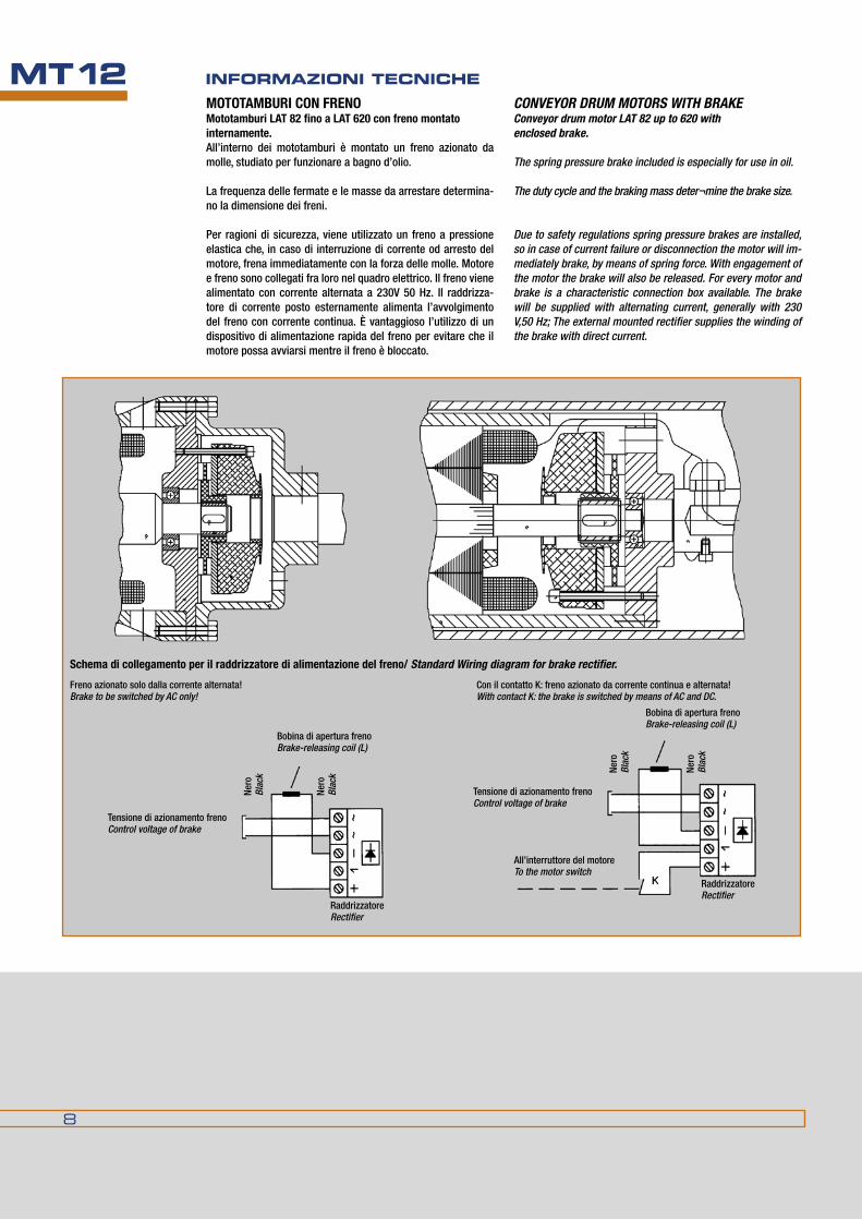
MT12 INfORMAzIONI TECNIChEMOTOTAMBURI CON FRENOMototamburi LAT 82 fino a LAT 620 con freno montato internamente.All’interno dei mototamburi è montato un freno azionato da molle, studiato per funzionare a bagno d’olio.
La frequenza delle fermate e le masse da arrestare determina-no la dimensione dei freni.
Per ragioni di sicurezza, viene utilizzato un freno a pressione elastica che, in caso di interruzione di corrente od arresto del motore, frena immediatamente con la forza delle molle. motore e freno sono collegati fra loro nel quadro elettrico. Il freno viene alimentato con corrente alternata a 230V 50 hz. Il raddrizza-tore di corrente posto esternamente alimenta l’avvolgimento del freno con corrente continua. È vantaggioso l’utilizzo di un dispositivo di alimentazione rapida del freno per evitare che il motore possa avviarsi mentre il freno è bloccato.
ConveyordrummoTorswiTHbrakeConveyor drum motor LAT 82 up to 620 with enclosed brake.
The spring pressure brake included is especially for use in oil.
The duty cycle and the braking mass deter¬mine the brake size.
due to safety regulations spring pressure brakes are installed, so in case of current failure or disconnection the motor will im-mediately brake, by means of spring force. With engagement of the motor the brake will also be released. for every motor and brake is a characteristic connection box available. The brake will be supplied with alternating current, generally with 230 V,50 Hz; The external mounted rectifier supplies the winding of the brake with direct current.
All’interruttore del motoreTo the motor switch
Schema di collegamento per il raddrizzatore di alimentazione del freno/ Standard Wiring diagram for brake rectifier.
Tensione di azionamento frenoControl voltage of brake
Tensione di azionamento frenoControl voltage of brake
raddrizzatoreRectifier
raddrizzatoreRectifier
nero
Blac
k nero
Blac
k
nero
Blac
k nero
Blac
k
freno azionato solo dalla corrente alternata!Brake to be switched by AC only!
bobina di apertura frenoBrake-releasing coil (L)
bobina di apertura frenoBrake-releasing coil (L)
Con il contatto K: freno azionato da corrente continua e alternata!With contact K: the brake is switched by means of AC and dC.

MT12
9
GENERAL TEChNICAL INfORMATIONMOTOTAMBURI CON DISPOSITIvO ANTIRITORNO INTERNO
GeneralitàTutti i mototamburi LAT sono fornibili con dispositivo antiritor-no inserito internamente. nei mototamburi più piccoli con cu-scinetti a ruota libera, nei più grandi con antiritorno calettato sull’albero. Grazie a questi dispositivi viene impedito l’arretra-mento del nastro che sta salendo quando si arresta il tamburo motore. Il dispositivo antiritorno, fornito a richiesta, viene mon-tato internamente dal lato dell’alimentazione elettrica. esso non richiede alcuna manutenzione. In tutti i casi il dispositivo antiritorno viene montato sull’albero del motore.
Senso di rotazioneuna freccia sul fondello portacuscinetti indica il senso di ro-tazione corretto, il senso contrario è bloccato. dopo il collega-mento nella sequenza delle fasi L1-L2-L3 ai morsetti u-V-W il motore girerà nel senso della libera rotazione. non cercare di far girare il motore in senso contrario!
Esempi di esecuzione
ConveyordrummoTorswiTHINTERNAL BACKSTOP
GeneralAll LAT conveyor drum motors are supplied with internal back-stop. With smaller types, rolling bearing or free running back-stop, and the larger with centrifugal backstop. This will, with rising conveyors, prevent backward run in the motionless pe-riods. The blocking direction is, with the order, fixed as seen on the terminal box. The backstop is fully maintenance free. In every case the backstop is situated on the motor shaft.
Direction of rotationAn arrow on the bearing plate indicates the free direction of rotation, the opposite rotation is blocked. With the connection pay attention to the phase sequence. To connect the phase se-quence L 1 - L2 - L3 on the terminal board to u - V - W will cause the motor to rotate in the free direction. do not try to run the motor against the backstop!
Examples of execution
Applicazione per potenze a partire da 5,5 kwApplication for power more than 5.5 kW
Applicazione per potenze inferiori a 4 kwApplication for power less than 4 kW

10
MT12 INfORMAzIONI TECNIChE
Schema di collegamento standard per mototamburo con motore trifase.
Standard wiring diagram for three-phase drummotor
Collegamentoelettricodimototamburoconalimentazioneacavo,motoretrifase
Electric connector drum motor with cable connection 3-motor
U2
V2W2
V1
U1 W1TC TC
L1 L2 L3
U2
V2W2
V1
U1 W1TC TC
L1 L2 L3
Senso orario / Clockwise rotation
L1 L2 L3
V1U1 W1 nero marron bleu giallo/verde black brown blue yellow/green
1 2 3
Senso orario / Clockwise rotation
L1 L2 L3
V1U1 W1 U21 2 3 4
V25
W26
nero marron bleu arancione grigio viola giallo/verde black brown blue orange grey violet yellow/green
Senso orario / Clockwise rotation
L1 L2 L3
V1U1 W1 U21 2 3 4
V25
W26
nero marron bleu arancione grigio viola giallo/verde black brown blue orange grey violet yellow/green
Senso orario / Clockwise rotation
mototamburo a bassa tensione (a triangolo) drum-motor – Low voltage
Senso orario / Clockwise rotation
mototamburo ad alta tensione (a stella) drum-motor – High voltage
mototamburo ad una tensione senza controllo termico
drum-motor with single voltage and without thermal control
mototamburo a due tensioni senza controllo termico Tensione bassa
drum-motor with dual - voltages. Low voltage
mototamburo a due tensioni senza controllo termico Alta tensione
drum-motor with dual-voltageHigh voltage
CoLLeGaMenTIeLeTTRICISTanDaRD
TensionePer la corretta definizione dell’avvolgimento del motore è ri-chiesta l’indicazione precisa della tensione di esercizio e del sistema di avviamento.Gli avvolgimenti standard sono i seguenti :motori fino a 2,2 kW 230/400 Volt triangolo/stellamotori oltre 3,0 kW 400 Volt triangolo.Tensioni speciali e frequenze speciali sono fornibili a richiesta.
Collegamenti elettriciVerificare che la tensione di esercizio prevista nella zona di in-stallazione sia uguale a quella alla quale è stato connesso il motore in fabbrica e le connessioni del mototamburo. In caso contrario occorre modificare i collegamenti nella morsettie-ra. La morsettiera é accessibile visibile dopo l’apertura del coperchio. Tutti i mototamburi LAT debbono essere collegati con un con-duttore di terra (Vde 0530).
Protezione del motoreLe sicurezze non proteggono il motore: il loro scopo é la prote-zione della linea contro i corti circuiti.Per proteggere l’avvolgimento di un motore a corrente alternata contro il sovraccarico termico provocato da un bloccaggio di un funzionamento a due fasi, si può scegliere una delle seguenti soluzioni :
Sensore di temperatura PTC (interno) in collegamento con un dispositivo di interruzione.Un contatto di protezione dell’avvolgimento (interno) (WT) come interruttore sull’avvolgimento dello statore, che stacca il motore in caso di sovraccarico di una protezione. essi non pro-teggono in caso di bloccaggio, perciò occorre prevedere anche un interruttore di sicurezza sul motore. Interruttore di sicurezza (esterno), con interruttore a bi-metallo, che apre il circuito in presenza di sbalzi di corrente eccessivi.
STANDARD ELECTRICAL CONNECTIONS
Operation voltagesfor the design of the motor winding we require information on operating voltage and starting method.The standard winding design for drum motors is as following:Motors up to 2.2 kW for 230/400V delta/star. Motors from 3.0 kW for 400V delta.Special voltages and frequencies are delivered on request.
ConnectionCheck whether the voltage and connections of the supplied equipment comply with the avail¬able voltage of the place of installation. If the above does not match, the connections on the termini block should be changed.on opening the termini box cover, the termini block is accessible.All LAT conveyor drum motors must be fitted with a ground ter-mini (VdE 0530).
Motor protection.fuses are no motor protection; they are especially for line pro-tection against short circuit.for the protection of the windings of a 3 phase motor, given thermal overload through locked rotor and 2 phase running, there is a choice on request of the following protection types:
Thermistors (internal) (PTC) in connection with a trip device.Winding thermostats (internal) ((WT) that open or close in the stator windings, which disconnect the motor on overload via a relay. These relays do not protect against locked rotor, for this case, in addition, motor protection switches are to be provided.
Motor protection switches (external) with bi-metal contacts, which open within admissible current input.

MT12
11
GENERAL TEChNICAL INfORMATIONCoLLeGaMenToeLeTTRICo/ ELECTRICAL CONNECTIONS
Attenzione: se il mototamburo è provvisto di encoder o freno, si dovrebbe usare un cavo schermato.Lo stesso vale per il collegamento del motore ad un misuratore di frequenza o ad analogo dispositivo di azionamento.
Important note: Screened cable should be used when the drum motor is supplied with encoder, brake, or connected to a frequency converter.
LAT 60 - LAT 82 LAT 113 - LAT 165 LAT 216 - ...
Tipo b: Connessione avvitata ad angolo ed 1m di cavo / Cable elbow connection plastic with 1m cable
a richiesta
on request
Tipo C: Connessione variabile con 1m di cavo / Variable cable design, pull release inside with 1m cable
a richiesta
on request
a richiesta
on request
Tipo d: Connessione avvitata diretta con 1m di cavo / straight cable connection with 1m di cable
Tipo e: pressacavo angolare acciaio inox con 1 m di cavo / angular cable gland, stainless steel with 1m di cable
a richiesta
on request
Tipo A: Scatole morsettiere / terminal box
LAT 113 - LAT 165
LAT 216 - LAT 321
LAT 415 - LAT 620

12
MT12 INfORMAzIONI TECNIChE
Senso orario / Clockwise rotation
L1 L2 L3
V1U1 W1 nero marron blu giallo/verde black brown blue yellow/green
1 2 3
Senso orario / Clockwise rotation
L1 L2 L3
V1U1 W1 TC nero marron blu rosso bianco giallo/verde black brown blue red white yellow/green
1 2 3 4TC
5
mototamburo ad un voltaggio senza controllo termico
drum-motor with single voltage and without thermal control
mototamburo ad un voltaggio con controllo termico
drum-motor with single voltage and thermal control
Senso orario / Clockwise rotation
L1 L2 L3
V1U1 W1 U21 2 3 4
V25
W26
nero marron blu arancio grigio viola giallo/verde black brown blue orange grey violet yellow/green
Senso orario / Clockwise rotation
L1 L2 L3
V1U1 W1 U21 2 3 4
V25
W26
nero marron blu arancio grigio viola giallo/verde black brown blue orange grey violet yellow/green
mototamburo a due tensioni. basso voltaggio
drum-motor with dual - voltages. Low voltage
mototamburo a due tensioni. Alto voltaggio
drum-motor with dual-voltage High voltage
Senso orario / Clockwise rotation
L1 L2 L3
V1U1 W1 U21 2 3 4
V25
W2 TC TC6 7 8
nero marron blu arancio grigio viola rosso bianco giallo/verde black brown blue orange grey violet red white yellow/green
Senso orario / Clockwise rotation
L1 L2 L3
V1U1 W1 U21 2 3 4
V25
W2 TC TC6 7 8
nero marron blu arancio grigio viola rosso bianco giallo/verde black brown blue orange grey violet red white yellow/green
mototamburo a doppio voltaggio e controllo termico. basso voltaggio
drum-motor with dual-voltage and thermal controlLow voltage
mototamburo a doppio voltaggio e controllo termico. Alto voltaggio
drum-motor with dual-voltage and thermal controlHigh voltage
CoLLeGaMenTIeLeTTRICIaCaVo
Collegamento elettrico di mototamburo con motore trifase e connessioneacavo.
CABLE ELECTRICAL CONNECTIONS
3-phase drum motor with cable electrical connection

MT12
13
GENERAL TEChNICAL INfORMATION
Senso orario / Clockwise rotation
L1 L2 L3
V1U1 W1 B+ nero marron blu rosso bianco giallo/verde black brown blue red white yellow/green
1 2 3 4B-
5
raddrizzatoreRectifier
Senso orario / Clockwise rotation
L1 L2 L3
V1U1 W1 B+1 2 3 4
B-5
TC TC6 7
nero marron blu rosa trasparente rosso bianco giallo/verde
raddrizzatoreRectifier
mototamburo con freno, ad un voltaggio senza controllo termico
drum-motor with brake, single voltage, no thermal control
mototamburo con freno, ad un voltaggio con controllo termico
drum-motor with brake, single voltage and thermal control
Senso orario / Clockwise rotation
L1 L2 L3
V1U1 W1 U21 2 3 4
V25
W2 B+ B-6 7 8
nero marron blu arancio grigio viola rosso bianco giallo/verde black brown blue orange grey violet red white yellow/green
raddrizzatoreRectifier
Senso orario / Clockwise rotation
L1 L2 L3
V1U1 W1 U21 2 3 4
V25
W2 B+ B-6 7 8
nero marron blu arancio grigio viola rosso bianco giallo/verde
raddrizzatoreRectifier
mototamburo con freno, doppio voltaggio senza controllo termicoVoltaggio basso
drum-motor with brake, dual voltage, and no thermal control Low voltage
mototamburo con freno, doppio voltaggio senza controllo termicoVoltaggio alto
drum-motor with brake, dual voltage, no thermal control High voltage
Senso orario /
L1 L2 L3
V1U1 W1 U21 2 3 4
V25
W2 B+ TCB- TC6 7 98 10
nero marron blu arancio grigio viola rosa trasparente rosso bianco giallo/verde black brown blue orange grey violet pink transparent red white yellow/green
raddrizzatoreRectifier
Senso orario /
L1 L2 L3
V1U1 W1 U21 2 3 4
V25
W2 B+ TCB- TC6 7 98 10
nero marron blu arancio grigio viola rosa trasparente rosso bianco giallo/verde black brown blue orange grey violet pink transparent red white yellow/green
raddrizzatoreRectifier
mototamburo con freno, doppio voltaggio con controllo termicoVoltaggio basso
drum-motor with brake, dual voltage and thermal controlLow voltage
mototamburo con freno, doppio voltaggio con controllo termicoVoltaggio alto
drum-motor with brake, dual voltage and thermal controlHigh voltage
CoLLeGaMenTIeLeTTRICIaCaVo
Collegamento elettrico di mototamburo con motore trifase, alimentazioneacavoefreno.
CABLE ELECTRICAL CONNECTIONS
3-phase drum motor with brake, cable eletrical connection

14
MT12 INfORMAzIONI TECNIChE
U2
V2W2
V1
U1 W1TC TC
L1 L2 L3
u1 1u - V1 1V - W1 1WW2 2u - u2 2V - V2 2W
U2
V2W2
V1
U1 W1TC TC
L1 L2 L3
u1 1u - V1 1V - W1 1WW2 2u - u2 2V - V2 2W
Senso orario / Clockwise rotation
mototamburo a velocità bassa
drum-motor slow speed
Senso orario / Clockwise rotation
mototamburo a velocità alta
drum-motor high speed
CoLLeGaMenTIeLeTTRICIaMoRSeTTIeRa
Collegamento elettrico di mototamburo con scatola morset-tieraemotoretrifaseaduevelocità.
BOx ELECTRICAL CONNECTIONS
3-phase, 2-speed drum motor with box electrical connection
CoLLeGaMenTIeLeTTRICIaCaVo
Collegamento elettrico di mototamburo con motore trifase e connessioneacavo.
CABLE ELECTRICAL CONNECTIONS
3-phase drum motor with cable electrical connection
Senso orario / Clockwise rotation
L1 L2 L3
1V1U 1W 2U1 2 3 4
2V5
2W6
nero marron blu arancio grigio viola giallo/verde black brown blue orange grey violet yellow/green
L1 L2 L3
Senso orario / Clockwise rotation
1V1U 1W 2U1 2 3 4
2V5
2W6
nero marron blu arancio grigio viola giallo/verde black brown blue orange grey violet yellow/green
mototamburo a velocità bassa
drum-motor slow speed
mototamburo a velocità alta
drum-motor high speed

MT12
15
GENERAL TEChNICAL INfORMATIONCoLLeGaMenTIeLeTTRICIaMoRSeTTIeRa
Collegamento elettrico di mototamburo con motore trifase e scatola morsettiera.
BOx ELECTRICAL CONNECTIONS
3-phase drum motor with electrical box connection.
U2
V2W2
V1
U1 W1TC TC
L1 L2 L3
U2
V2W2
V1
U1 W1TC TC
L1 L2 L3
Senso orario / Clockwise rotation
mototamburo a bassa tensione(a triangolo)drum-motor – Low voltage
Senso orario / Clockwise rotation
mototamburo ad alta tensione (a stella)drum-motor – High voltage
U2
V2W2
V1
U1 W1TC TC
L1 L2 L3
Controllo termicoThermal control
U2
V2W2
V1
U1 W1TC TC
L1 L2 L3
Controllo termicoThermal control
Senso orario / Clockwise rotation
mototamburo con controllo termico basso voltaggio (a triangolo) drum-motor with thermal control - Low voltage
Senso orario / Clockwise rotation
mototamburo con controllo termico alto voltaggio (a stella)drum-motor with thermal control - High voltage

16
MT12 INfORMAzIONI TECNIChECoLLeGaMenTIeLeTTRICIaMoRSeTTIeRa
Collegamento elettrico di mototamburo con motore trifase, scatola morsettiera e freno.
BOx ELECTRICAL CONNECTIONS
3-phase drum motor with brake, box electrical connection.
U2
V2W2
V1
U1 W1TC TC
L1 L2 L3
frenoBrake
freno
raddrizzatoreRectifier
Tensione di azionamento alternata (AC)
Control voltage (AC)
+
U2
V2W2
V1
U1 W1TC TC
L1 L2 L3
frenoBrake
frenoBrake
raddrizzatoreRectifier
Tensione di azionamento alternata (AC)
Control voltage (AC)
+
Controllo termicoThermal control
Senso orario / Clockwise rotation
mototamburo con freno, ad un voltaggio senza controllo termico
drum-motor with brake, single voltage no thermal control
Senso orario / Clockwise rotation
mototamburo con freno, ad un voltaggio con controllo termico
drum-motor with brake, single voltage and with thermal control
U2
V2W2
V1
U1 W1TC TC
L1 L2 L3
frenoBrake
frenoBrake
raddrizzatoreRectifier
Tensione di azionamento alternata (AC)
Control voltage (AC)
+
U2
V2W2
V1
U1 W1TC TC
L1 L2 L3
frenoBrake
frenoBrake
raddrizzatoreRectifier
Tensione di azionamento alternata (AC)
Control voltage (AC)
+
Senso orario / Clockwise rotation
mototamburo con freno, a doppio voltaggio senza controllo termicobasso voltaggio
drum-motor with brake, dual voltage no thermal controlLow voltage
Senso orario / Clockwise rotation
mototamburo con freno, a doppio voltaggio senza controllo termicoAlto voltaggio
drum-motor with brake, dual voltage and without thermal controlHigh voltage

MT12
17
GENERAL TEChNICAL INfORMATION
CoLLeGaMenTIeLeTTRICIMonoFaSeaMoRSeTTIeRa
Collegamento elettrico di mototamburo monofase con scatola morsettiera
sinGLePHaseboxeLeCTriCaLConneCTions
Single phase drum motor box electrical connection
U2
V2W2
V1
U1 W1TC TC
L1 N
Condensatore Capacitor
u1 u1 - u2 u2V1 z1 - V2 z2
Condensatore Capacitor
U2
V2W2
V1
U1 W1TC TC
L1 N
Controllo termicoThermal control
u1 u1 - u2 u2V1 z1 - V2 z2
Senso orario / Clockwise rotation
mototamburo senza controllo termicodrum-motor without thermal control
Senso orario / Clockwise rotation
mototamburo con controllo termico drum-motor with thermal control
Senso orario Clockwise rotation
Senso orario Clockwise rotation
CoLLeGaMenTIeLeTTRICIMonoFaSeaCaVo
Collegamento elettrico di mototamburo monofase con connessioneacavodiretto.
CabLesinGLePHaseeLeTTriCaLConneCTions
Single phase drum motor direct cable eletrical connection.
Schema di collegamento senza controllo termicoWiring diagram, no termal control
Schema di collegamento con controllo termicoWiring diagram with thermal control
motore/Motor1] nero/blach - u12] bleu/blue - u23] marron/brown - z14] Grigio/grey - z2
Verde/Giallo protez. messa a terragreen/yellow protective earth
motore/Motor1] nero/blach - u12] bleu/blue - u23] marron/brown - z14] Grigio/grey - z25] rosso/red - TC Controllo termico6] bianco/white - TC Thermal control Verde/Giallo protez. messa a terragreen/yellow protective earth
L1
Z2Z1U1U2
N
Condensatore
L1
Z2Z1U1U2
N
Condensatore Capacitor

18
MT12 INfORMAzIONI TECNIChE
Tutte le dimensioni sono soggette a tolleranze di lavorazione e benché i disegni e le illustrazioni siano fedeli, non sono tuttavia impegnativi. La duGOmruLLI si riserva di modificare i propri prodotti senza preavviso.La riproduzione anche parziale delle figure e del testo è vietata a norma del C.C. e della legge sui diritti d’autore.
All dimensions are subject to machining tolerances, and although drawings and illustrations are exact, they place the manufacturer under no obligation whatsoever.duGoMRuLLI reserves the right to modify their products at any time without notice. Even a part reproduction of present catalogue’s illustrations, and text, is forbidden.

MOTOTAMbURI LAT
1
MT13SChEdE PROdOTTOSElEcTION chARTS
Rev. 01/16

2
MOTOTAMbURI PER TRASPORTATORI A NASTROSChEdE PROdOTTOMT13
MototamburoDrum diam.
PotenzePower-range
velocità del nastroBelt speed
mm. P2(kW) v (m/sec)
mm. min. max. min. max
Ø 60 0,03 0,08 0,09 1,90
Ø 82 0,018 0,12 0,05 0,92
Ø 113 0,075 0,55 0,09 3,47
Ø 138 0,09 1,00 0,04 2,75
Ø 165 0,37 3,0 0,19 5,18
Ø 216 0,37 3,0 0,25 2,20
Ø 321 1,50 7,5 0,39 3,28
Ø 415 3,0 15 0,60 2,17
Ø 518 4,0 22 0,51 2,14
Ø 620 7,5 22 0,77 2,56
Ø 630 30 55 1,25 4,00
LAT Ø 60-630Programma di produzione in sintesi.Reference table.

3
CONvEyOR dRUM MOTORSSELECTION ChARTS MT13
Diametro mototamburoDrum diameter Ø 60 Ø 82 Ø 113 Ø 138 Ø 165 Ø 216 Ø 321 Ø 415 Ø 518 Ø 620 Ø 630 Ø 630
Antiritorno meccanicoMechanical backstop X X X X X X X X X X X X
freno elettromagneticoElectromagnetic brake X X X X X X X X X X X
Sonda termostatica nell’avvolgimentoWinding with thermostats X X X X X X X X X X X
esecuzione inoxCorrosion proof design X X X X X X a richiesta / on request
rivestimento in gomma neraRubber coating black X X X X X X X X X X X
rivestimento in gomma bianca alimentareRubber coating white – food processing X X X X X
esecuzione elettrozincataGalvanised X X X X X X X X X X
motore a due velocitàMotor with 2 speeds X X X X X X
Protezione a labirinto IP66IP 66 labyrinth seal X standard standard standard standard X X X X X
esecuzione con cavo direttodesign with cable gland standard X X
esecuzione con morsettieradesign with terminal box X X X standard
esecuzione per due voltaggidesign for 2 voltages X X X X X X X X X X X
Supporto ad incastro Clamping bearings X X X X X X X X X X
Esecuzioni a richiesta – accessoriAuxiliary equipment

4
MOTOTAMbURI PER TRASPORTATORI A NASTROSChEdE PROdOTTOMT13
Mototamburi LAT per materiali alla rinfusaLAT drum motors for bulk handling
Mototamburi LAT per carichi isolati Lat drum motors for unit handling

5
CONvEyOR dRUM MOTORSSELECTION ChARTS MT13
Indice pag.
Schede tecniche
LAT60 6
LAT82 8
LAT113 10
LAT138 14
LAT165 18
LAT216 20
LAT321 22
LAT415 24
LAT518 26
LAT620 28
LAT630 30
Supporti 32
Table of contents pag.
Selection charts
LAT60 6
LAT82 8
LAT113 10
LAT138 14
LAT165 18
LAT216 20
LAT321 22
LAT415 24
LAT518 26
LAT620 28
LAT630 30
Clamping bearings 32

6
MOTOTAMbURI PER TRASPORTATORI A NASTROSChEdE PROdOTTOMT13
Tamburo motore / Conveyor Drum Motor standard IP65standard IP65
a richiesta IP66on request IP66
modellosize
TipoType
D1 D2 d e f b EL b EL
60 LAT 60.1 61,5 62,5 20 14 18 2,5 L + 5 2,5 L + 5
60 INOX LAT 60.1 63,5 64,5
Tamburodirinvio/Guidedrum
60 LUT 60.1 61,5 62,5 20 14 18 2,5 L + 5 2,5 L + 5
60 INOX LAT 60.1 63,5 64,5
LAT Ø 60 LAT Ø 60
TamburodirinviotipoLUT60(standard) GuidedrumtypeLuT60(standard)
Mototamburo tipo LAT 60 (standard) LAT 60 Conveyor Drum Motor (standard)
dimensioni in mm / dimensions are in mm
version Duscita cavo dirittaStraight cable gland
version Euscita cavo angolare acciaio inoxAngular cable gland stainless steel
version BCavo con fissaggio ad angoloAngular cable gland
Con un metro di cavoWith 1 m cable
version Cuscita cavo a fissaggio regolabile diritto/angolareRight angle-straight variable

7
CONvEyOR dRUM MOTORSSELECTION ChARTS MT13
LaTØ60–adunavelocità LAT Ø 60 – with one speed
Weight of complete unit with oilAdditional weight: add around 0,5 Kg. /100 mm.Add. Length inclusive oil filling
Standard lengths (L): 355, 365, 400, 450, ……800Description of Standard-Motor:• Barrel shaped shell, bright steel with rustproof coating.• Bearing covers made of aluminium with rustproof coating. • flattened bilateral trunions made of steel with rustproof
coating.• Planetary gearing with steel toothing.• With 1 m cable and angular or straight gland.
Peso del mototamburo compresa carica di olio.Il peso varia di circa 0,5 Kg. Ogni 100 mm di lunghezza, olio compreso.
Lunghezze standard (L) : 355, 365, 400, 450, ……800.Descrizione del mototamburo standard:• Tamburo con mantello tornito biconico. Acciaio naturale
trattato con antiruggine.• fondelli in alluminio con trattamento anticorrosione.• Asse in acciaio trattato con antiruggine.• riduttore planetario con ingranaggi in acciaio, • fornito completo di cavo lungo 1 metro con fissaggio di-
ritto o ad angolo.
altrecombinazionidipotenzaevelocitàarichiesta
*Per tamburi con protezione IP 66 la lunghezza minima L sale a 365 MM.
Deviated power and speed combinations on request
*With IP 66 L min. raises to365 MM.
Scheda tecnica / Selection charts
Dati tecnici / Drum data Peso/Weight
Tipo P2 v n2 F T2 I [400v] L min. L = 450 mm
Type [kW] [m/s] [min -1] [n] [nm] [Amp.] [mm] [kg]
LAT 60.1 0,034-pol.
0,09 26 345 11
0,19 355* 6
0,11 34 265 8
0,14 41 219 7
0,15 45 204 6
0,18 54 168 5
0,22 65 139 4
0,59 178 51 2
0,76 232 39 1
0,92 280 32 1
LAT 60.1 0,082-pol.
0,18 54 447 14
0,24 355* 6
0,23 71 343 11
0,28 85 284 9
0,3 92 264 8
0,37 111 218 7
0,44 134 180 6
1,21 366 66 2
1,57 477 51 2
1,9 576 42 1
LUT 60.1 ---- Tamburodirinvio/Guidedrum 355a richiestaon request
8
MOTOTAMbURI PER TRASPORTATORI A NASTROSChEdE PROdOTTOMT13LAT Ø 82 LAT Ø 82
TamburodirinviotipoLUT82(standard) GuidedrumtypeLuT82(standard)
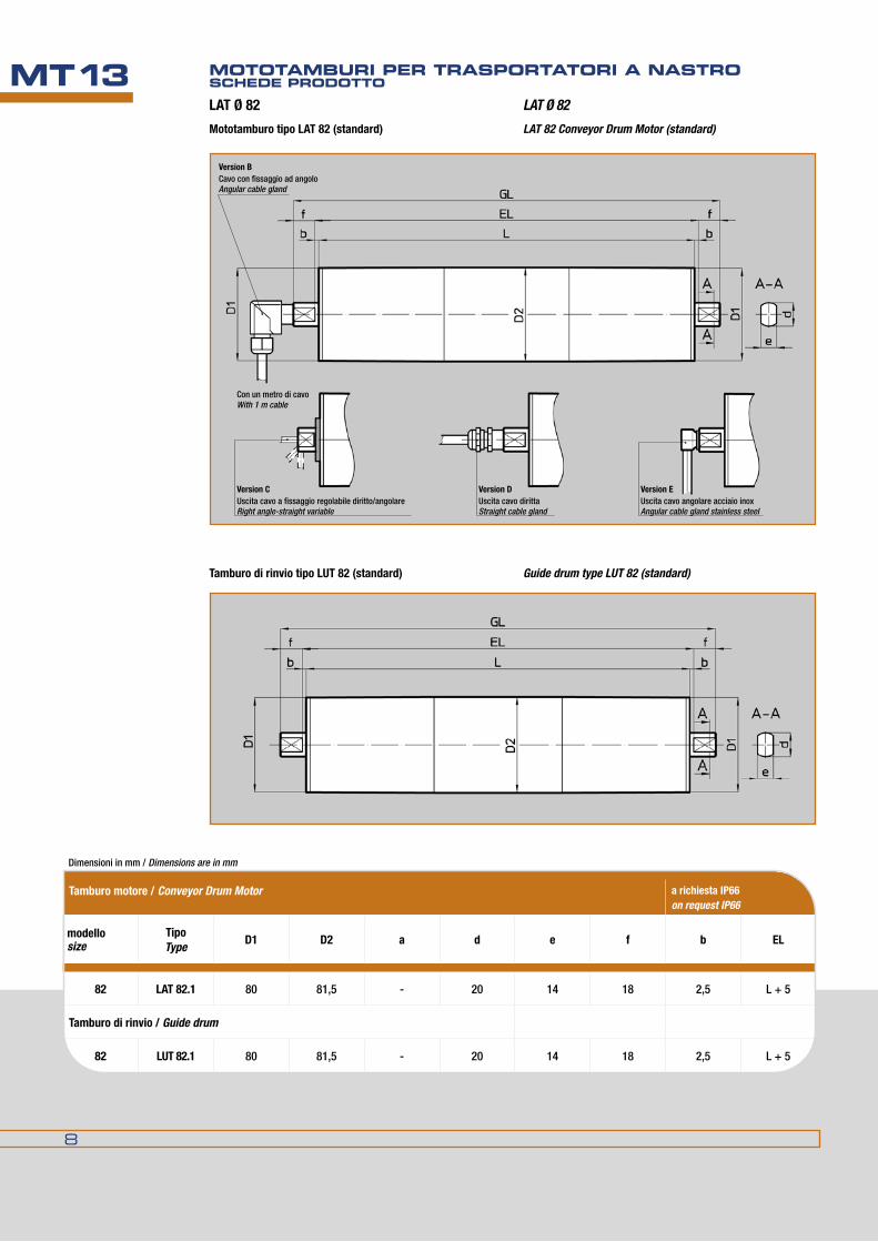
Mototamburo tipo LAT 82 (standard) LAT 82 Conveyor Drum Motor (standard)
Tamburo motore / Conveyor Drum Motor a richiesta IP66on request IP66
modellosize
TipoType
D1 D2 a d e f b EL
82 LAT 82.1 80 81,5 - 20 14 18 2,5 L + 5
Tamburodirinvio/Guidedrum
82 LUT 82.1 80 81,5 - 20 14 18 2,5 L + 5
dimensioni in mm / dimensions are in mm
version Duscita cavo dirittaStraight cable gland
version Euscita cavo angolare acciaio inoxAngular cable gland stainless steel
version BCavo con fissaggio ad angoloAngular cable gland
Con un metro di cavoWith 1 m cable
version Cuscita cavo a fissaggio regolabile diritto/angolareRight angle-straight variable

9
CONvEyOR dRUM MOTORSSELECTION ChARTS MT13
LaTØ82–adunavelocità LAT Ø 82 – with one speed
altrecombinazionidipotenzaevelocitàarichiesta
*Per IP66 Lmn = 205
Peso del mototamburo compresa carica di olioIl peso varia di circa 0,8 Kg. Ogni 100 mm di lunghezza, olio compreso.
Lunghezze standard (L): 200, 250, 300, 350 ……800.
Descrizione del mototamburo standard:• Tamburoconmantellotornitobiconico,acciaionaturale con trattamento antiruggine.• Fondelliportacuscinettiinalluminiocontrattamento anticorrosione.• Assefresatoalleestremitàinacciaiocontrattamento antiruggine.• Riduttoreaingranaggielicoidaleinacciaio (particolarmente silenzioso).• Fornitocompletodicavolungo1metroconfissaggioadangolo.• Completamentesmontabile
Deviated power and speed combinations on request
*For IP66 execution Lmn = 205
Weight of complete unit with oil.Additional weight: add around 0,8 Kg. /100 mm.Add. Length inclusive oil filling.
Standard lengths (L): 200, 250, 300, 350 ……800.
Description of Standard-Motor:• Barrelshapedshell,brightsteelwithrustproofcoating.• Bearingcoversmadeofaluminiumwithrustproofcoating.• Flattenedbilateraltrunionsmadeofsteelwithrustproof coating.• Helicalgearingwithsteeltoothing(lownoiselevel)• With1mcableandangulargland.• Completedisassemblypossible
Scheda tecnica / Selection charts
Dati tecnici / Drum data Peso/Weight
Tipo P2 v n2 F T2 I [400v] L min. L = 250 mm
Type [kW] [m/s] [min -1] [n] [nm] [Amp.] [mm] [kg]
LAT 82.1 0,0188-pol.
0,03 8 537 22
0,46 250* 4,5
0,05 11 375 150,06 14 305 120,09 20 209 90,12 29 146 60,15 36 119 5
LAT 82.1 0,044-pol.
0,08 19 482 20
0,23 200* 3,5
0,10 22 419 170,14 32 292 120,17 39 238 100,25 58 163 70,35 83 114 50,43 101 93 4
LAT 82.1 0,072-pol.
0,18 43 384 16
0,20 200* 3,5
0,21 49 334 140,30 70 233 90,37 87 190 80,54 126 130 50,77 181 91 40,95 222 74 3
LAT 82.1 0,074-pol.
0,08 20 827 34
0,37 250 4,5
0,10 23 718 290,14 33 501 200,17 40 408 170,25 59 279 110,36 84 195 80,44 103 159 6
LAT 82.1 0,122-pol.
0,19 43 647 26
0,31 250* 4,5
0,21 50 562 230,31 72 392 160,38 88 319 130,55 129 218 90,79 185 152 60,97 227 124 5
LUT 82.1 ---- Tamburodirinvio/Guidedrum 250* 5

10
MOTOTAMbURI PER TRASPORTATORI A NASTROSChEdE PROdOTTOMT13
TamburodirinviotipoLUT113(standard) GuidedrumtypeLuT113(standard)
Con un metro di cavoWith 1 m cable
version AScatola morsettieraTerminal box
LAT Ø 113 LAT Ø 113
Mototamburo tipo LAT 113 (standard) LAT 113 Conveyor Drum Motor (standard)
Tamburo motore / Conveyor Drum Motor standard IP66standard IP66
modellosize
TipoType
D1 D2 a N d e f f1 b* EL
113 LAT 113.1 112,5 113,5 43 100 25 20 25 23 5 L+10
Tamburodirinvio/Guidedrum
113 LUT 113.1 - 113,5 - - 25 20 25 5 L+10
dimensioni in mm / dimensions are in mm
version Duscita cavo dirittaStraight cable gland
version BCavo con fissaggio ad angoloAngular cable gland
version Cuscita cavo a fissaggio regolabile diritto/angolareRight angle-straight variable
version Euscita cavo angolare acciaio inoxAngular cable gland stainless steel

11
CONvEyOR dRUM MOTORSSELECTION ChARTS MT13
Scheda tecnica / Selection charts
Dati tecnici Mototamburo / Drum data Peso/Weight
Tipo P2 v n2 F T2 I [400v] L min. L = 400 mmType [kW] [m/s] [min -1] [n] [nm] [Amp.] [mm] [kg]
LAT 113.1 0,0758-pol.
0,09 16 795 45
0,45 260 12,5
0,12 19 650 370,14 23 541 310,16 28 456 260,19 33 388 220,23 38 333 190,26 44 286 160,28 47 271 150,34 57 221 130,41 68 184 100,48 81 155 90,57 95 132 80,66 111 113 60,77 129 98 6
LAT 113.1 0,126-pol.
0,14 23 876 50
0,57 260 12,5
0,17 28 716 410,20 34 596 340,24 40 503 290,28 47 428 240,33 55 367 210,38 64 316 180,40 68 299 170,49 83 244 140,59 99 203 120,70 118 171 100,82 138 146 80,96 162 125 71,11 188 108 6
LAT 113.1 0,184-pol.
0,21 36 845 48
0,68 260 12,5
0,26 44 690 390,31 53 575 330,37 63 485 270,44 73 413 230,51 86 354 200,59 99 304 170,63 105 288 160,76 129 235 130,92 155 196 111,09 183 165 91,28 215 141 81,49 251 121 71,73 292 104 6
LaTØ113–adunavelocità LAT Ø 113 – with one speed

12
MOTOTAMbURI PER TRASPORTATORI A NASTROSChEdE PROdOTTOMT13
Scheda tecnica / Selection charts
Dati tecnici Mototamburo / Drum data Peso/Weight
Tipo P2 v n2 F T2 I [400v] L min. L = 400 mmType [kW] [m/s] [min -1] [n] [nm] [Amp.] [mm] [kg]
LAT 113.1 0,254-pol.
0,21 36 1173 67
0,94 260 12,5
0,26 44 959 540,31 53 798 450,37 63 673 380,44 73 573 330,51 86 491 280,59 99 423 240,63 105 400 230,76 129 327 190,92 155 272 151,09 183 229 131,28 215 195 111,49 251 167 101,73 292 144 8
LAT 113.1 0,304-pol.
0,21 36 1408 80
1,10 280 13,6
0,26 44 1151 650,31 53 958 540,37 63 808 460,44 73 688 390,51 86 589 330,59 99 507 290,63 105 480 270,76 129 392 220,92 155 326 191,09 183 275 161,28 215 234 131,49 251 201 111,73 292 173 10
LAT 113.1 0,372-pol.
0,43 72 868 49
0,95 260 12,5
0,52 88 710 400,63 105 591 340,74 125 498 280,87 147 424 241,02 171 363 211,18 199 313 181,25 210 296 171,53 257 242 141,84 309 201 112,18 367 170 102,56 431 145 82,99 503 124 73,47 584 107 6
LaTØ113–adunavelocità LAT Ø 113 – with one speed

13
CONvEyOR dRUM MOTORSSELECTION ChARTS MT13
Scheda tecnica / Selection charts
Dati tecnici Mototamburo / Drum data Peso/Weight
Tipo P2 v n2 F T2 I [400v] L min. L = 400 mmType [kW] [m/s] [min -1] [n] [nm] [Amp.] [mm] [kg]
LAT 113.1 0,552-pol.
0,42 71 1300 74
1,26 260 13,6
0,52 87 1062 600,62 105 884 500,74 124 746 420,87 146 635 361,01 170 544 311,17 198 469 271,24 209 443 251,52 256 362 211,82 307 301 172,16 364 254 142,54 428 216 122,97 499 185 113,44 579 160 9
LaTØ113–adunavelocità LAT Ø 113 – with one speed
altrecombinazionidipotenzaevelocitàarichiesta
Peso del mototamburo compresa carica di olio.Il peso varia di circa 1 Kg. Ogni 100 mm di lunghezza, olio com-preso.
Per l’esecuzione con freno la lunghezza minima aumenta di 65 mm. Lunghezze standard (L): 260, 280, 300, 350, ....800
Descrizione del mototamburo standard:• Tamburoconmantellotornitobiconico.Acciaionaturale con trattamento antiruggine.• Fondelliportacuscinettiinalluminiocontrattamentoanti corrosione.• Assefresatoalleestremitàinacciaiocontrattamentoanti ruggine.• Riduttoreaingranaggielicoidaliinacciaio (particolarmente silenzioso).• Fornitocompletodicavolungo1metroconfissaggioadangolo.• Completamentesmontabile.
Deviated power and speed combinations on request
Weight of complete unit with oilAdditional weight: add around 1 Kg. /100 mm.Add. Length inclusive oil filling.
In case of design with brake the minimum L length is extended by 65 mm. Standard lengths (L): 260, 280, 300, 350, ....800
Description of Standard-Motor:• Barrelshapedshell,brightsteelwithrustproofcoating.• Bearingcoversmadeofaluminiumwithrustproofcoating.• Flattenedbilateraltrunionsmadeofsteelwithrustproof coating.• Helicalgearingwithsteeltoothing(lownoiselevel)• With1mcableandangulargland.• Completedisassemblypossible

14
MOTOTAMbURI PER TRASPORTATORI A NASTROSChEdE PROdOTTOMT13LAT Ø 138 LAT Ø 138
TamburodirinviotipoLUT138(standard) GuidedrumtypeLuT138(standard)
Mototamburo tipo LAT 138 (standard) LAT 138 Conveyor Drum Motor (standard)
dimensioni in mm / dimensions are in mm
Con un metro di cavoWith 1 m cable
version AScatola morsettieraTerminal box
version Duscita cavo dirittaStraight cable gland
version BCavo con fissaggio ad angoloAngular cable gland
version Cuscita cavo a fissaggio regolabile diritto/angolareRight angle-straight variable
version Euscita cavo angolare acciaio inoxAngular cable gland stainless steel
Tamburo motore / Conveyor Drum Motor standard IP66standard IP66
modellosize
TipoType D1 D2 a N c d e f f1 b EL
138.1 LAT 138.1 137,5 139 43 100 2,5 30 20 25 23 15 L + 30
Tamburodirinvio/Guidedrum
138.1 LAT 138.1 137,5 139 - - 2,5 30 20 25 - 15 L + 30

15
CONvEyOR dRUM MOTORSSELECTION ChARTS MT13
LaTØ138–adunavelocità LAT Ø 138 – with one speed
Scheda tecnica / Selection charts
Dati tecnici / Drum data Peso/Weight
Tipo P2 v n2 F T2 I [400v] L min. L = 400 mm
Type [kW] [m/s] [min -1] [n] [nm] [Amp.] [mm] [kg]
LAT 138 0,0912-pol.
0,04 6 2218 153
0,82 300 15
0,05 7 1797 1240,06 8 1478 1020,07 9 1362 940,08 10 1198 830,11 15 826 570,08 11 1093 750,1 14 908 63
0,12 17 728 500,16 23 550 380,15 21 591 410,19 26 479 330,25 34 363 250,31 43 291 200,41 57 220 15
LAT 138 0,188-pol.
0,07 9 2739 189
0,80 300 15
0,08 11 2219 1530,1 14 1826 126
0,11 15 1683 1160,12 17 1480 1020,13 18 1350 930,16 22 1122 770,18 24 1020 700,2 28 900 62
0,25 34 731 500,26 37 680 470,3 42 592 410,4 56 449 310,5 69 360 25
0,66 92 272 19
LAT 138 0,256-pol.
0,09 12 2782 192
0,85 300 15
0,11 15 2254 1560,13 19 1855 1280,15 20 1709 1180,17 23 1503 1040,18 25 1371 950,22 30 1139 790,24 33 1036 710,27 38 914 630,34 47 742 510,36 50 691 480,42 58 601 410,55 76 456 310,68 95 366 250,91 125 276 19

16
MOTOTAMbURI PER TRASPORTATORI A NASTROSChEdE PROdOTTOMT13
Scheda tecnica / Selection charts
Dati tecnici Mototamburo / Drum data Peso/Weight
Tipo P2 v n2 F T2 I [400v] L min. L = 400 mmType [kW] [m/s] [min -1] [n] [nm] [Amp.] [mm] [kg]
LAT 138 0,254-pol.
0,14 19 1848 128
0,80 300 15
0,17 23 1497 1030,2 28 1232 85
0,22 30 1135 780,25 35 998 690,27 38 911 630,33 46 757 520,35 50 688 470,41 57 607 420,51 70 493 340,55 75 459 320,63 87 388 280,83 114 303 211,03 143 243 171,36 189 183 13
LAT 138 0,374-pol.
0,14 19 2735 189
1,10 300 15
0,17 23 2216 1530,2 28 1823 126
0,22 30 1680 1160,25 35 1477 1020,27 38 1348 930,33 46 1120 770,36 50 1018 700,41 57 898 620,51 70 729 500,55 75 679 470,63 87 591 410,83 114 448 311,03 143 359 251,36 189 271 19
LAT 138 0,554-pol.
0,2 28 2740 189
1,60 300 15
0,22 30 2525 1740,25 34 2220 1530,27 38 2025 1400,33 45 1683 1160,36 50 1530 1060,41 56 1350 930,5 69 1096 76
0,54 75 1020 700,62 86 888 610,82 113 673 461,02 141 540 371,35 187 408 28
LAT 138 0,754-pol.
0,32 44 1338 161
2,20 300 15
0,35 49 2125 1470,4 55 1875 129
0,49 68 1522 1050,53 73 1417 980,61 84 1233 850,8 111 935 651 138 750 52
1,32 183 566 39
LaTØ138–adunavelocità LAT Ø 138 – with one speed

17
CONvEyOR dRUM MOTORSSELECTION ChARTS MT13
Scheda tecnica / Selection charts
Dati tecnici Mototamburo / Drum data Peso/Weight
Tipo P2 v n2 F T2 I [400v] L min. L = 400 mmType [kW] [m/s] [min -1] [n] [nm] [Amp.] [mm] [kg]
LAT 138 0,752-pol.
0,27 37 2802 193
1,90 300 15
0,33 46 2270 1570,4 56 1868 129
0,44 60 1721 1190,5 69 1513 104
0,54 75 1381 950,65 90 1148 790,72 99 1043 720,81 113 920 64
1 139 747 521,08 149 696 481,24 171 605 421,63 226 459 322,04 282 368 252,7 373 278 19
LAT 138 0,902-pol.
0,33 46 2695 186
1,95 300 15
0,41 56 2218 1530,44 61 2044 1410,5 69 1797 124
0,55 76 1639 1130,66 91 1362 940,73 101 1239 850,82 114 1093 751,01 140 887 611,09 151 826 571,25 173 719 501,65 229 545 382,06 285 437 302,73 377 330 23
LAT 138 1,004-pol.
0,32 45 2795 193
2,6 300 15
0,35 49 2541 1750,4 56 2241 155
0,49 68 1820 1260,53 74 1694 1170,61 85 1474 1020,81 111 1118 77
1 139 897 621,33 184 677 47
LUT 138 ---- Tamburodirinvio/Guidedrum 320 13,00
altrecombinazionidipotenzaevelocitàarichiestaPeso del mototamburo compresa carica di olio. Il peso varia di circa 2 Kg. Ogni 100 mm di lunghezza, olio compreso.
Per l’esecuzione con freno la lunghezza minima aumenta di 55 mm. Lunghezze standard (L): 300, 350, 400…..1350 Descrizione del mototamburo standard:•Tamburoconmantellotornitobiconico.Acciaionaturale con trattamento antiruggine. •Fondelliportacuscinettiinalluminiocontrattamentoanti corrosione. •Assefresatoalleestremitàinacciaiocontrattamentoantiruggine.
Deviated power and speed combinations on requestWeight of complete unit with oil Additional weight: add around 2 Kg. /100 mm. Add. Length inclusive oil filling.
In case of design with brake the minimum L length is extended by 55 mm. Standard lengths (L): 300, 350, 400…..1350 Description of Standard-Motor:•Barrelshapedshell,brightsteelwithrustproofcoating.•Bearingcoversmadeofaluminumwithrustproofcoating.•Flattenedbilateraltrunionsmadeofsteelwithrustproof coating.
LaTØ138–adunavelocità LAT Ø 138 – with one speed

18
MOTOTAMbURI PER TRASPORTATORI A NASTROSChEdE PROdOTTOMT13
Tamburo motore / Conveyor Drum Motor standard IP66standard IP66
modellosize
TipoType
D1 D2 a N d e f f1 b EL
165 LAT 165.1 164 165 43 100 40 30 45 43 20 L + 40
Tamburodirinvio/Guidedrum
165 LUT 165.1 164 165 - - 40 30 45 20 L + 40
LAT Ø 165 LAT Ø 165
TamburodirinviotipoLUT165(standard) GuidedrumtypeLuT165(standard)
Mototamburo tipo LAT 165 (standard) LAT 165 Conveyor Drum Motor (standard)
dimensioni in mm / dimensions are in mm
Con un metro di cavoWith 1 m cable
version AScatola morsettieraTerminal box
version Duscita cavo dirittaStraight cable gland
version BCavo con fissaggio ad angoloAngular cable gland
version Cuscita cavo a fissaggio regolabile diritto/angolareRight angle-straight variable
version Euscita cavo angolare in acciaio inoxAngular cable gland stainless steel

19
CONvEyOR dRUM MOTORSSELECTION ChARTS MT13
Scheda tecnica / Selection charts
Dati tecnici Mototamburo / Drum data Peso/Weight
Tipo P2 v n2 F T2 I [400v] L min. L = 500 mmType [kW] [m/s] [min -1] [n] [nm] [Amp.] [mm] [kg]
LAT 165.1 0,378-pol.
0,19 22 1911 158
1,50 400 44,0
0:24 27 1573 1300,28 33 1315 1080,33 39 1111 920,39 45 946 780,46 53 810 670,54 63 682 560,66 76 562 460,79 91 470 390,93 108 397 331,09 127 338 281,28 148 289 24
LAT 165.1 0,756-pol.
0,25 29 2947 243
2,20 400 44,0
0,31 36 2427 2000,37 43 2028 1670,44 51 1714 1410,51 59 1460 1200,60 69 1249 1030,71 82 1053 870,87 100 867 711,04 120 724 601,23 142 612 511,44 167 521 431,68 195 446 37
LAT 165.1 1,104-pol.
0,39 45 2841 234
3,00 400 44,0
0,47 54 2339 1930,56 65 1955 1610,67 77 1652 1360,78 91 1407 1160,91 106 1204 991,08 126 1014 841,32 152 835 691,58 182 698 581,86 216 590 492,19 253 502 412,56 296 430 35
LAT 165.1 1,504-pol.
0,56 65 2656 219
3,60 425 47,0
0,67 77 2245 1850,78 91 1911 1580,92 106 1636 1351,09 126 1378 1141,32 153 1135 941,58 183 949 781,87 217 802 662,20 254 683 562,57 297 584 48
LAT 165.1 2,202-pol.
0,78 91 2805 231
4,30 425 47,0
0,95 110 2310 1911,14 132 1931 1591,35 156 1632 1351,58 183 1389 1151,85 214 1189 982,20 254 1002 832,67 309 825 683,19 369 690 573,78 437 583 484,43 513 496 415,18 600 425 35
LAT 165.1 3,002-pol.
0,78 91 3860 318
6,80 492 48,0
0,94 110 3178 2621,13 132 2656 2191,34 156 2245 1851,57 183 1911 1581,83 214 1636 1352,18 254 1378 1142,64 309 1135 943,16 369 949 783,74 437 802 664,39 513 683 565,13 600 584 48
LaTØ165–adunavelocità LAT Ø 165 – with one speed
Altre combinazioni di potenza evelocitàarichiesta
Peso del mototamburo compresa carica di olio.Il peso varia di circa 3 Kg. Ogni 100 mm, di lunghezza, olio compreso.Per l’esecuzione con freno la lunghezza minima aumenta di 110 mm.Lunghezze standard (L): 400, 425, 450, 500 ..... 1300.
Deviated power and speed combinations on request
Weight of complete unit with oilAdditional weight: add around 3 Kg. /100 mm.Add. Length inclusive oil filling.In case of design with brake the minimum L length is extended by 110 mm.Standard lengths (L): 400, 425,450, 500 .... 1300.

20
MOTOTAMbURI PER TRASPORTATORI A NASTROSChEdE PROdOTTOMT13LAT Ø 216 LAT Ø 216
TamburodirinviotipoLUT216(standard) GuidedrumtypeLuT216(standard)
Mototamburo tipo LAT 216 (standard) LAT 216 Conveyor Drum Motor (standard)
Tamburo motore / Conveyor Drum Motor standard IP65standard IP65
a richiesta IP66on request IP66
a richiesta IP67on request IP67
modellosize
TipoType D1 D2 a N c d e f f1 b EL b EL b EL
216 LAT 216.0 213,5 216 95 112 3 40 30 45 45 - - 20 L + 40 a richiestaon request
a richiestaon request
216 LAT 216.1 213,5 216 95 112 3 40 30 55 55 20 L + 40 20 L + 40 37 L + 74
Tamburodirinvio/Guidedrum
216 LUT 216.0 213,5 216 - - 3 40 30 45 - - - 20 L + 40 a richiestaon request
a richiestaon request
216 LUT 216.1 213,5 216 - - 3 40 30 55 - 20 L + 40 20 L + 40 37 L + 74
dimensioni in mm / dimensions are in mm
version AScatola morsettieraTerminal box
version Duscita cavo diritta
Straight cable gland
version BCavo con fissaggio ad angoloAngular cable gland
Con un metro di cavoWith 1 m cable
21
CONvEyOR dRUM MOTORSSELECTION ChARTS MT13
Scheda tecnica / Selection charts
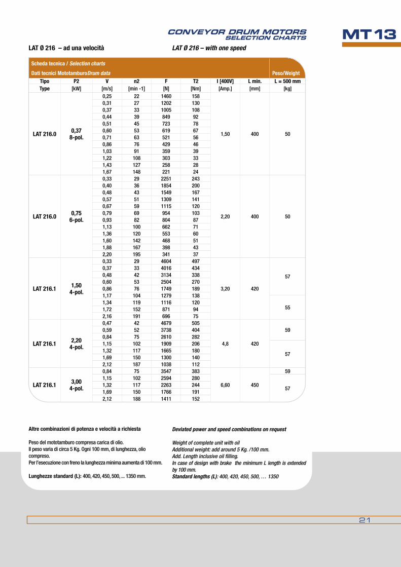
Dati tecnici MototamburoDrum data Peso/WeightTipo P2 v n2 F T2 I [400v] L min. L = 500 mmType [kW] [m/s] [min -1] [n] [nm] [Amp.] [mm] [kg]
LAT 216.0 0,378-pol.
0,25 22 1460 158
1,50 400 50
0,31 27 1202 1300,37 33 1005 1080,44 39 849 920,51 45 723 780,60 53 619 670,71 63 521 560,86 76 429 461,03 91 359 391,22 108 303 331,43 127 258 281,67 148 221 24
LAT 216.0 0,756-pol.
0,33 29 2251 243
2,20 400 50
0,40 36 1854 2000,48 43 1549 1670,57 51 1309 1410,67 59 1115 1200,79 69 954 1030,93 82 804 871,13 100 662 711,36 120 553 601,60 142 468 511,88 167 398 432,20 195 341 37
LAT 216.1 1,504-pol.
0,33 29 4604 497
3,20 420
57
0,37 33 4016 4340,48 42 3134 3380,60 53 2504 2700,86 76 1749 1891,17 104 1279 138
551,34 119 1116 1201,72 152 871 942,16 191 696 75
LAT 216.1 2,204-pol.
0,47 42 4679 505
4,8 420
590,59 52 3738 4040,84 75 2610 2821,15 102 1909 206
571,32 117 1665 1801,69 150 1300 1402,12 187 1038 112
LAT 216.1 3,004-pol.
0,84 75 3547 383
6,60 450
591,15 102 2594 280
571,32 117 2263 2441,69 150 1766 1912,12 188 1411 152
LaTØ216–adunavelocità LAT Ø 216 – with one speed
altrecombinazionidipotenzaevelocitàarichiesta
Peso del mototamburo compresa carica di olio.Il peso varia di circa 5 Kg. Ogni 100 mm, di lunghezza, olio compreso.Per l’esecuzione con freno la lunghezza minima aumenta di 100 mm.
Lunghezze standard (L): 400, 420, 450, 500, ... 1350 mm.
Deviated power and speed combinations on request
Weight of complete unit with oilAdditional weight: add around 5 Kg. /100 mm.Add. Length inclusive oil filling.In case of design with brake the minimum L length is extended by 100 mm.Standard lengths (L): 400, 420, 450, 500, … 1350

22
MOTOTAMbURI PER TRASPORTATORI A NASTROSChEdE PROdOTTOMT13LAT Ø 321 LAT Ø 321
TamburodirinviotipoLUT321(standard) GuidedrumtypeLuT321(standard)
Mototamburo tipo LAT 321 (standard) LAT 321 Conveyor Drum Motor (standard)
Tamburo motore / Conveyor Drum Motor standard IP66standard IP66
a richiesta IP67on request IP67
modellosize
TipoType D1 D2 a N c d e f f1 b EL b EL
321 LAT 321.0 318 321 95 112 3 40 30 55 55 20 L + 40 45 L + 90
321 LAT 321.1 318 321 95 112 3 45 35 53 53 22 L + 44 43 L + 86
Tamburodirinvio/Guidedrum
321 LUT 321.0 318 321 - - 3 40 30 55 - 20 L + 40 45 L + 90
321 LUT 321.1 318 321 - - 3 45 35 53 - 22 L + 44 43 L + 86
dimensioni in mm / dimensions are in mm
version AScatola morsettieraTerminal box
version Duscita cavo diritta
Straight cable gland
version BCavo con fissaggio ad angoloAngular cable gland
Con un metro di cavoWith 1 m cable

23
CONvEyOR dRUM MOTORSSELECTION ChARTS MT13
Scheda tecnica / Selection charts
Dati tecnici Mototamburo / Drum data Peso/Weight
Tipo P2 v n2 F T2 I [400v] L min. L = 600 mmType [kW] [m/s] [min -1] [n] [nm] [Amp.] [mm] [kg]
LAT 321.0 1,504-pol.
0,48 29 3098 497
3,20 520 95
0,56 33 2702 4340,71 42 2109 3380,89 53 1685 2701,11 66 1356 2181,27 76 1177 1891,74 104 861 1382,00 119 751 1202,34 139 641 103
LAT 321.1
2,204-pol.
0,39 23 5622 902
4,80 550
1200,48 28 4593 737
LAT 321.0
0,70 42 3148 505
100
0,87 52 2516 4041,09 65 2025 3251,25 75 1756 2821,71 102 1285 2061,96 117 1121 1802,30 137 957 154
LAT 321.1
3,004-pol.
0,60 36 4986 800
6,60 550
1250,74 44 4070 653
LAT 321.0
0,84 50 3564 572
1051,09 65 2751 4421,26 75 2387 3831,72 102 1746 2801,97 117 1523 244
LAT 321.14,00
4-pol.
0,73 44 5465 877
9,00 550
1301,08 64 3694 593
LAT 321.01,33 79 3019 484
1101,66 99 2411 3872,03 121 1968 316
LAT 321.15,50
4-pol.
1,04 62 5282 848
11,50 680 140
1,28 76 4312 6921,65 98 3324 5332,04 121 2697 4332,68 159 2054 3303,28 195 1677 269
LAT 321.17,50
4-pol.
1,65 98 4532 727
15,50 680 1502,04 121 3678 5902,68 159 2801 4503,28 195 2287 367
LUT 321.0/1 ---- Tamburodirinvio/Guidedrum 520 a richiesta on request
LaTØ321–adunavelocità LAT Ø 321 – with one speed
altrecombinazionidipotenzaevelocitàarichiesta
Peso del mototamburo compresa carica di olio.Il peso varia di circa 6 Kg. Ogni 100 mm. di lunghezza, olio compreso Per l’esecuzione con freno la lunghezza minima aumenta di 130 mm.Lunghezze standard (L): 520, 550, 600, 680, ……1600.Descrizione del mototamburo standard:• Tamburo con mantello tornito biconico acciaio naturale con trattamento antiruggine.• Fondelliportacuscinettiinghisagrigia,verniciataRAL2002.• Assefresatoalleestremitàinacciaiocontrattamentoantiruggine.• Riduttoreagradiniconingranaggiinacciaio(bassarumorosità).• ScatolamorsettierainalluminioverniciataRAL2002.• Completamentesmontabile
Deviated power and speed combinations on request
Weight of complete unit with oilAdditional weight: add around 6 Kg. /100 mm.Add. Length inclusive oil filling.In case of design with brake the minimum L length is extended by 130 mm.Standard lengths (L): 520, 550, 600, 680, ,……1600Description of Standard-Motor:• Barrelshapedshell,brightsteelwithrustproofcoating.• Bearingcoversmadeofcastiron,withcoatingRAL2002.• Flattenedbilateraltrunionsmadeofsteelwithrustproofcoating.• Helicalgearingwithsteeltoothing(lownoiselevel)• AlluminiumterminalboxpaintedRAL2002• Completedisassemblypossible

24
MOTOTAMbURI PER TRASPORTATORI A NASTROSChEdE PROdOTTOMT13LAT Ø 415 LAT Ø 415
TamburodirinviotipoLUT415(standard) GuidedrumtypeLuT415(standard)
Mototamburo tipo LAT 415 (standard) LAT 415 Conveyor Drum Motor (standard)
Tamburo motore / Conveyor Drum Motor standard IP66standard IP66
a richiesta IP67on request IP67
modellosize
TipoType D1 D2 a N c d e f f1 b EL b EL
415 LAT 415.0 413 415 95 112 3 45 35 53 53 22 L + 44 32 L + 64
415 LAT 415.1 413 415 100 150 5 60 50 75 75 25 L + 50 35 L + 70
Tamburodirinvio/Guidedrum
415 LUT 415.0 413 415 - - 3 45 35 53 - 22 L + 44 32 L + 64
415 LUT 415.1 413 415 - - 5 60 50 75 - 25 L + 50 35 L + 70
dimensioni in mm / dimensions are in mm

25
CONvEyOR dRUM MOTORSSELECTION ChARTS MT13
Scheda tecnica / Selection charts
Dati tecnici Mototamburo / Drum data Peso/Weight
Tipo P2 v n2 F T2 I [400v] L min. L = 750 mmType [kW] [m/s] [min -1] [n] [nm] [Amp.] [mm] [kg]
LAT 415.0 3,004-pol.
0,78 36 3857 800
3,20 550 1600,95 44 3148 653
1,32 61 2276 472
1,61 74 1858 386
LAT 415.1
4,004-pol.
0,60 28 6678 1386
9,00
750 2750,84 39 4746 985
LAT 415.0
0,95 44 4227 877
550 1701,31 60 3056 634
1,60 74 2495 518
2,08 96 1923 399
LAT 415.1 5,504-pol.
0,87 40 6344 1316
11,50 750 290
1,04 48 5267 1093
1,29 59 4266 885
1,56 72 3530 733
1,72 79 3201 664
2,17 100 2534 526
LAT 415.1 7,504-pol.
1,04 48 7182 1490
15,50 750 300
1,29 59 5818 1207
1,56 72 4814 999
1,72 79 4365 906
2,17 100 3456 717
LAT 415.1 10,004-pol.
1,28 59 7811 1621
21,00 750 3201,55 71 6464 1341
1,71 79 5861 1216
2,16 99 4640 963
LAT 415.1 15,004-pol.
1,71 79 8792 182429,50 750 360
2,16 99 6959 1444
LUT 415.0/1 ---- Tamburodirinvio/Guidedrum 520
a richiesta on request
LAT Ø 415 – with one speed
altrecombinazionidipotenzaevelocitàarichiesta
Peso del mototamburo compresa carica di olio.Il peso varia di circa 10 Kg. Ogni 100 mm, di lunghezza, olio compreso.Per l’esecuzione con freno la lunghezza minima aumenta di 200 mm.Lunghezze standard (L): 550, 600, 650, …1400 mm
Descrizione del mototamburo standard:• Tamburoconmantellotornitobiconico.Acciaionaturale con trattamento antiruggine.• Fondelliportacuscinettiinghisagrigia,verniciataRAL2002.• Assefresatoalleestremitàinacciaiocontrattamentoantiruggine.• Riduttoreaingranaggielicoidaliinacciaio (particolarmente silenzioso).• ScatolamorsettierainalluminioverniciataRAL2004.• Completamentesmontabile.
Deviated power and speed combinations on request
Weight of complete unit with oilAdditional weight: add around 10 Kg. /100 mm.Add. Length inclusive oil filling.In case of design with brake the minimum L length is extended by 200 mmStandard lengths (L): 550, 600, 650, … 1400 mm
Description of Standard-Motor:• Barrelshapedshell,brightsteelwithrustproofcoating.• Bearingcoversmadeofcastiron,withcoatingRAL2002.• Flattenedbilateraltrunionsmadeofsteelwithrustproof coating.• Helicalgearingwithsteeltoothing(lownoiselevel)• AluminiumterminalboxpaintedRAL2004.• Completedisassemblypossible
LaTØ415–adunavelocità

26
MOTOTAMbURI PER TRASPORTATORI A NASTROSChEdE PROdOTTOMT13LAT Ø 518 LAT Ø 518
Mototamburo tipo LAT 518 (standard) LAT 518 Conveyor Drum Motor (standard)
Tamburo motore / Conveyor Drum Motor standard IP65standard IP65
a richiesta IP66/67on request IP66/67
modellosize
TipoType D1 D2 a N c d e f f1 b EL b EL
518 LAT 518.0 515 518 100 150 5 60 50 75 75 25 L + 50 35 L + 70
518 LAT 518.1 515 518 100 150 5 75 65 85 85 30 L + 60 45 L + 90
Tamburodirinvio/Guidedrum
518 LUT 518.0 515 518 - - 5 60 50 75 - 25 L + 50 35 L + 70
518 LUT 518.1 515 518 - - 5 75 65 85 - 30 L + 60 45 L + 90
TamburodirinviotipoLUT518(standard) GuidedrumtypeLuT518(standard)
dimensioni in mm / dimensions are in mm

27
CONvEyOR dRUM MOTORSSELECTION ChARTS MT13
LaTØ518–adunavelocità LAT Ø 518 – with one speed
altrecombinazionidipotenzaevelocitàarichiesta
Peso del mototamburo compresa carica di olio.Il peso varia di circa 10 Kg. Ogni 100 mm, di lunghezza, olio compreso.Per l’esecuzione con freno la lunghezza minima aumenta di 200 mm.Lunghezze standard (L): 750, 800, 820, 850... 1600
Descrizione del mototamburo standard:• Tamburo con mantello tornito biconico acciaio naturale con trattamento antiruggine.• Fondelliportacuscinettiinghisagrigia,verniciataRAL2004.• Assefresatoalleestremitàinacciaiocontrattamentoantiruggine.• Riduttorea ingranaggi elicoidali in acciaio (bassa rumorosità).• ScatolamorsettierainalluminioverniciataRAL2004.• Completamentesmontabile
Deviated power and speed combinations on request
Weight of complete unit with oilAdditional weight: add around 10 Kg. /100 mm.Add. Length inclusive oil filling.In case of design with brake the minimum L length is extended by 200 mm.Standard lengths (L): 750, 800, 820, 850... 1600
Description of Standard-Motor:•Barrelshapedshell,brightsteelwithrustproofcoating.•Bearingcoversmadeofcastiron,withcoatingRAL2004.•Flattenedbilateraltrunionsmadeofsteelwithrustproofcoating.•Helicalgearingwithsteeltoothing(lownoiselevel).•AlluminiumterminalboxpaintedRAL2004.•Completedisassemblypossible
Scheda tecnica / Selection charts
Dati tecnici Mototamburo / Drum data Peso/Weight
Tipo P2 v n2 F T2 I [400v] L min. L = 950 mm
Type [kW] [m/s] [min -1] [n] [nm] [Amp.] [mm] [kg]
LAT 518.1 4,004-pol.
0,51 19 7813 20249,00 750 350
0,63 23 6396 1657
LAT 518.1
5,504-pol.
0,53 19 10445 2705
11,50
820 3600,64 24 8551 2215
0,84 31 6545 1695
LAT 518.01,08 40 5083 1316
750 3351,30 48 4219 1093
1,61 59 3418 885
LAT 518.1
7,504-pol.
0,64 24 11660 3020
15,50
820 375
0,84 31 8924 2311
1,07 39 7012 1816
1,31 48 5740 1487
1,55 57 4845 1255
LAT 518.01,61 59 4661 1207
750 3401,94 72 3857 999
2,14 79 3497 906
LAT 518.1 10,004-pol.
0,83 31 11982 3103
21,00 820 462
1,06 39 9415 2438
1,30 48 7707 1996
1,54 57 6506 1685
1,70 63 5899 1528
2,08 77 4817 1248
LAT 518.1 15,004-pol.
1,31 48 11480 2973
29,50 800 4481,55 57 9691 2510
1,71 63 8787 2276
2,09 77 7176 1859
LAT 518.1 18,504-pol.
1,59 58 11668 3022
37,00 850 4701,75 64 10580 2740
2,14 79 8640 2238
LAT 518.1 22,004-pol.
1,75 64 12582 325943,50 850 470
2,14 79 10275 2661
LUT 518.0/1 ---- Tamburodirinvio/Guidedrum 650
a richiesta on request

28
MOTOTAMbURI PER TRASPORTATORI A NASTROSChEdE PROdOTTOMT13LAT Ø 620 LAT Ø 620
Mototamburo tipo LAT 620 (standard) LAT 620 Conveyor Drum Motor (standard)
Tamburo motore / Conveyor Drum Motor standard IP65standard IP65
a richiesta IP66on request IP66
modellosize
TipoType D1 D2 a N c d e f f1 b EL b EL
620 LAT 620.0 618 620 100 150 5 75 65 85 85 30 L + 60 45 L + 90
Tamburodirinvio/Guidedrum
620 LUT 620.0 618 620 5 75 65 85 30 L + 60 45 L + 90
TamburodirinviotipoLUT620(standard) GuidedrumtypeLuT620(standard)
dimensioni in mm / dimensions are in mm

29
CONvEyOR dRUM MOTORSSELECTION ChARTS MT13
LaTØ620–adunavelocità LAT Ø 620 – with one speed
altrecombinazionidipotenzaevelocitàarichiesta
Peso del mototamburo compresa carica di olio.Il peso varia di circa 25 Kg. Ogni 100 mm, di lunghezza, olio compreso.Per l’esecuzione con freno la lunghezza minima aumenta di 200 mm.
Lunghezze standard (L): 800, 850, 900......1700
Descrizione del mototamburo standard:• Tamburoconmantellotornitobiconicoacciaionaturale con trattamento antiruggine.• Fondelliportacuscinettiinghisagrigia,verniciataRAL2004.• Assefresatoalleestremitàinacciaiocontrattamento antiruggine.• Riduttoreaingranaggielicoidaliinacciaio(bassarumorosità).• ScatolamorsettierainalluminioverniciataRAL2004.• Completamentesmontabile
Deviated power and speed combinations on request
Weight of complete unit with oilAdditional weight: add around 25 Kg. /100 mm.Add. Length inclusive oil filling.In case of design with brake the minimum L length is extended by 200 mm.
Standard lengths (L): 800, 850, 900..... 1700
Description of Standard-Motor:•Barrelshapedshell,brightsteelwithrustproofcoating.•Bearingcoversmadeofcastiron,withcoatingRAL2004.•Flattenedbilateraltrunionsmadeofsteelwithrustproof coating.•Helicalgearingwithsteeltoothing(lownoiselevel)•AlluminiumterminalboxpaintedRAL2004•Completedisassemblypossible
Scheda tecnica / Selection charts
Dati tecnici Mototamburo / Drum data Peso/Weight
Tipo P2 v n2 F T2 I [400v] L min. L = 950 mmType [kW] [m/s] [min -1] [n] [nm] [Amp.] [mm] [kg]
LAT 620.0 7,504-pol.
0,77 24 9742 3020
15,50 820 5201,01 31 7456 2311
1,28 39 5858 1816
LAT 620.0 10,004-pol.
1,00 31 10011 3103
21,00 820 530
1,27 39 7866 2438
1,55 48 6439 1996
1,84 57 5435 1685
2,03 63 4929 1528
2,48 77 4025 1248
LAT 620.0 15,004-pol.
1,56 48 9592 2973
29,50 800 5551,85 57 8097 2510
2,04 63 7342 2276
2,50 77 5995 1859
LAT 620.0 18,504-pol.
1,90 58 9749 3022
37,00 850 5952,09 64 8840 2740
2,56 79 7219 2238
LAT 620.0 22,004-pol.
2,09 64 10512 325943,50 850 600
2,56 79 8584 2661
LUT 620.0 ---- Tamburodirinvio/Guidedrum 750 a richiesta on request

30
MOTOTAMbURI PER TRASPORTATORI A NASTROSChEdE PROdOTTOMT13LAT Ø 630 LAT Ø 630
Mototamburo tipo LAT 630 (standard) LAT 630 Conveyor Drum Motor (standard)
Tamburo motore / Conveyor Drum Motor standard IP66standard IP66
a richiesta IP67on request IP67
modellosize
TipoType D1 D2 a b2 d1 d2 e1 f1 h1 h2 L2 L3 EL EL
630 LAT 630.1 626 630 165 80 90 26 250 320 100 183 150 117 L + 300 L + 300
Tamburodirinvio/Guidedrum
630 LUT 630.1 626 630 - 80 90 26 250 320 100 183 150 117 --- L + 300
TamburodirinviotipoLUT630(standard) GuidedrumtypeLuT630(standard)
dimensioni in mm / dimensions are in mm
SupportoPedestrial bearing
morsettieraTerminal box
SupportoPedestrial bearing

31
CONvEyOR dRUM MOTORSSELECTION ChARTS MT13
LaTØ630–adunavelocità LAT Ø 630 – with one speed
altrecombinazionidipotenzaevelocitàarichiesta
Peso del mototamburo compresa carica di olio.Il peso varia di circa 25 Kg. Ogni 100 mm, di lunghezza, olio compreso
Lunghezza standard (L): 950, 1000, 1050, ……. 2000 mm
Descrizione del mototamburo standard:• Tamburoconmantellotornitobiconicoacciaionaturale con trattamento antiruggine.• Fondelliportacuscinettiinghisagrigia,verniciataRAL2004.• Assefresatoalleestremitàinacciaiocontrattamento antiruggine.• Riduttoreaingranaggielicoidaliinacciaio (bassa rumorosità).• ScatolamorsettierainalluminioverniciataRAL2004.• Completamentesmontabile
Deviated power and speed combinations on request
Weight of complete unit with oilAdditional weight: add around 25 Kg. /100 mm.Add. Length inclusive oil filling.
Standard lengths (L): 950, 1000, 1050, ……. 2000 mm
Description of Standard-Motor:•Barrelshapedshell,brightsteelwithrustproofcoating.•Bearingcoversmadeofcastiron,withcoatingRAL2004•Flattenedbilateraltrunionsmadeofsteelwithrustproof coating.•Helicalgearingwithsteeltoothing(lownoiselevel)•AlluminiumterminalboxpaintedRAL2004•Completedisassemblypossible
Scheda tecnica / Selection charts
Dati tecnici Mototamburo / Drum data Peso/Weight
Tipo P2 v n2 F T2 I [400v] L min. L = 950 mmType [kW] [m/s] [min -1] [n] [nm] [Amp.] [mm] [kg]
LAT 630.1 30,008-pol.
1,25 38 22791 7179
57
950
825
1,60 49 17807 5609
2,00 61 14245 4487
2,50 76 11394 3589
3,15 95 9045 2849
LAT 630.1 37,006-pol.
1,60 49 21969 6920
70 8252,00 61 17569 5534
2,50 76 14054 4427
3,15 95 11153 3513
LAT 630.1 45,004-pol.
2,50 76 17092 5384
85 8453,15 95 13565 4273
4,00 121 10683 3365
LAT 630.1 55,004-pol.
2,50 76 20902 6584
105 8453,15 95 16581 5223
4,00 121 13057 4115
LUT 630.1 ---- Tamburodirinvio/Guidedrum 950a richiesta on request

32
MOTOTAMbURI PER TRASPORTATORI A NASTROSChEdE PROdOTTOMT13LAT 60 – 620 LAT 60 – 620
Supporti ad incastro per mototamburi LAT Clamping bearing for LAT conveyor drum motors
Attention: the LAT conveyor drum motors are for horizontal mounting only with vertically flattened mounting shaft. Excep-tions from the normal assembling must be agreed with the order.Pay also attention: the marking “top” on the connection side (red point) must not be at the bottom otherwise lubrication and cooling will not be guaranteed.
Attenzione: i mototamburi LAT sono costruiti esclusivamente per essere montati in orizzontale con piani di fresatura assi verticali. montaggi diversi debbono essere precisati in fase di ordinazione.Fare attenzione che la marcatura « oben » dal lato di ingresso del cavo di alimentazione elettrica (punto rosso) non sia mai rivolta verso il basso, perché in tal caso non sarebbero garantiti né il raffreddamento, né la lubrificazione.

33
CONvEyOR dRUM MOTORSSELECTION ChARTS MT13
Tamburo motore / Conveyor Drum Motor
Mototamburo tipoDrum type
Supporto Clamping bearing d e h h1 h2 m n s w z M Materiale
MaterialPeso Kg ca.
Wt. Kg
LAT 60.1 EL20/14 20 14 12 28 47 80 100 6,5 15 5 m5
AcciaioSteel
0,25
LAT 82.1 EL20/14 20 14 12 28 47 80 100 6,5 15 5 m5 0,25
LAT 113.1 EL25/20 25 20 21 44,5 66 100 140 12 20 8 m6 0,7
LAT 138.1 EL30/20 30 20 21 44,5 68,5 100 140 12 24 8 m6 0,7
LAT 165.1 EL40/30 A 40 30 20 47 78,5 110 160 14 40 10 m8
GhisaCast iron
1,5
LAT 216.0 EL40/30 A 40 30 20 47 76 110 160 14 40 10 m8 1,5
LAT 216.1 EL40/30 B 40 30 21 67 102,5 140 190 18 50 12 m8 2,8
LAT 321.0 EL40/30 B 40 30 21 67 102,5 140 190 18 50 12 m8 2,8
LAT 321.1 EL45/35 45 35 21 67 105 140 190 18 50 12 m8 2,8
LAT 415.0 EL45/35 45 35 21 67 105 140 190 18 50 12 m8 2,8
LAT 415.1 EL60/50 60 50 22 70 119,5 160 220 18 60 20 m12
AcciaioSteel
5
LAT 518.0 EL60/50 60 50 22 70 119,5 160 220 18 60 20 m12 5
LAT 518.1 EL75/65 75 65 38 100 162,5 240 345 22 70 28 m16 13,5
LAT 620.0 EL75/65 75 65 38 100 162,5 240 345 22 70 28 m16 13,5
dimensioni in mm / dimensions are in mm

34
MOTOTAMbURI PER TRASPORTATORI A NASTROSChEdE PROdOTTOMT13
Tutte le dimensioni sono soggette a tolleranze di lavorazione e benché i disegni e le illustrazioni siano fedeli, non sono tuttavia impegnativi. La duGOmruLLI si riserva di modificare i propri prodotti senza preavviso.La riproduzione anche parziale delle figure e del testo è vietata a norma del C.C. e della legge sui diritti d’autore.
All dimensions are subject to machining tolerances, and although drawings and illustrations are exact, they place the manufacturer under no obligation whatsoever.duGoMRuLLI reserves the right to modify their products at any time without notice. Even a part reproduction of present catalogue’s illustrations, and text, is forbidden.

MOTOTAMbURI LAT
USO E MANUTENzIONEOPERATING INSTRUcTIONS
1
MT15
Rev. 01/16

2
MT15 USO E MANUTENzIONEINDICE
1. Istruzioni importanti1.1 Significato dei simboli1.2 Generalità
2.avvisodiSicurezza2.1 Impiego previsto2.2 Istruzioni di sicurezza
3. Informazioni generiche 3.1 motori elettrici3.2 Voltaggio3.3 frequenza – Inverter3.4 rendimenti3.5 rumorosità
4.accettazioneeconservazionedellamerce4.1 Accettazione della merce4.2 Immagazzinamento4.2.1 Generalità4.2.2 motori con rivestimenti in gomma
5. Installazione e montaggio dei mototamburi LAT 5.1 movimentazione5.2 Posizione di montaggio del motore5.3. montaggio dei perni di articolazione5.4 funzionamento inverso5.5 mototamburo con antiritorno5.6 Tensione del nastro
6. connessione elettrica di un mototamburo LAT6.1 Generalità 6.2. Tipi di motore6.2.1 mototamburi a una velocità 6.2.2 mototamburi a doppia velocità6.3 Versioni a connessione6.3.1.1 blocco terminale e direzione della rotazione6.3.1.2 Connessione a terra con cassetta terminale6.3.1.3 materiale6.4 freno
7. Funzionamento dei mototamburi LAT7.1 Aumento di temperatura / Classe di isolamento7.2 funzionamento con nastro trasportatore
8. Manutenzione e assistenza8.1 Pulizia8.2 Lubrificazione / sostituzione dell’olio8.2.1 Lubrificazione8.2.2 Sostituzione dell’olio8.3 Sostituzione dei cuscinetti 8.4 Protezioni a labirinto8.5 freno8.6 rivestimento in gomma
9. Soppressione dell’interferenza della frequenza radio
10. Protezione del motore
11.Garanzie
CONTENTS 1. Important instructions
1.1 Instruction symbols in the operating instructions1.2 General Instructions
2. Safety Notes
2.1 Intended use2.2 General safety instructions
3.Generalinformation
3.1 Electric motors3.2 Voltage3.3 frequency – Inverters3.4 output rating3.5 Noise Levels
4. Receipt of goods and storage
4.1 Receipt of goods 4.2 Storage4.2.1 General aspects4.2.2 Motors with rubber coatings
5. Installation and assembly of LAT-drum motors
5.1 Handling5.2 Motor mounting position5.3 Mounting of the trunnions5.4 Reversing duty5.5 drum motors with backstop5.6 Belt tension
6. Electrical connection of a LAT-drum motor
6.1 General6.2 Motor Types6.2.1 drum -motors with single speed6.2.2 drum motors with double speeds6.3 Connection Versions6.3.1.1 Terminal block and direction of rotation6.3.1.2 Grounding with Terminal Box6.3.1.3 Material6.4 Brake
7. Operation of LAT-Drum Motors
7.1 Temperature rise / Insulation Class7.2 operation with conveyor belt
8. Maintenance and Care
8.1 Cleaning8.2 Lubrication / oil Change8.2.1 Lubrication8.2.2 oil Change8.3 Replacing bearings8.4 Labyrinth Seals8.5 Brake8.6 Rubber lining
9. Radio frequency interference suppression
10. Motor Protection
11. Warranties

3
MT15OPERATING INSTRUCTIONS1. ISTRUzIONI IMPORTANTI
1.1 Significato dei simboli
1. IMPORTANT INSTRUCTIONS 1.1 Instruction symbols in the operating instructions
Pericolo: pericolo di morte o di ferita.
Attenzione: rischio per il mototamburo o per l’ambiente circostante
Note: Infomazioni utili.
Danger: possible consequences: death or very severe injuries.
Caution: possible consequences: damage of the engine and the environment.
Note: Pointers for application and useful Information.
1.2Generalità
Il presente manuale fa parte della fornitura ed è valido per tutte le versioni standard dei seguenti mototamburi:LAT060, LAT080, LAT110, LAT113, LAT165, LAT174, LAT216, LAT321, LAT415, LAT518, LAT620 e LAT630.
Per i mototamburi e gli accessori in esecuzione speciale valgono le istruzioni che saranno fornite caso per caso.Si considerino gli ulteriori manuali in dotazione per i componenti accessori, etc.
non si accettano responsabilità per danni causati dalla mancata osservanza delle presenti istruzioni, che debbono essere conservate in prossimità del mototamburo.
Leggere le istruzioni prima d’intervenire sul mototamburo.
Solo una precisa conoscenza di queste istruzioni garantisce un funzionamento affidabile e privo d’inconvenienti.
Le presenti istruzioni riflettono lo stato delle conoscenze tecniche al momento della stampa.
nell’interesse del progresso tecnico ci riserviamo il diritto di apportare ai nostri prodotti le modifiche necessarie per preservarne le caratteristiche migliorandone il funzionamento e l’affidabilità.
Queste istruzioni sono coperte da copyright e non possono essere riprodotte o rese note a terzi senza nostra autorizzazione
modifiche o correzioni possono essere fatte solo da noi a pena di decadenza dalla garanzia.
1.2Generalinstructions The present manual is a component of supply. This manual applies to all standard versions of the LAT-drum motors:LAT060, LAT080, LAT110, LAT113, LAT165, LAT174, LAT216, LAT321, LAT415, LAT518, LAT620 and LAT630.
Special types of drive and their accessory components are governed by the special contractual agreements and technical document.Please consider the further provided manuals for accessory components, etc..
We accept no responsibilty for damage or disruption resulting from disregard of these operating instructions.
Keep this operating instructions in the vicinity of the motor.
Read these operating instructions before working with the drive.only a precise knowledge of these operating instructions will guarantee reliable faultfree operation.The drives described in these instructions reflect the state of technical development at the time these instructions went to print.In the interest of technical progress we reserve the right to make changes to the individual assemblies and accessories which we regard as necessary to preserve their essential characteristics and improve the efficiency and safety of the drive.These operating instructions are Copyrighted. These operating instructions must not be wholly or partly reproduced, used in any unauthorised way for competitive purposes or made available to third parties without our agreement.Amendments or addtions to these operating instructions may be made only by us; otherwise any guarantee claim against us will lapse.

4
MT15 USO E MANUTENzIONE2. SAFETY NOTES
2.1 Intended UseThe LAT-drum motors covered in these operating instructions have been developed for the stationary use in general engineering. As long as not otherwise agreed, the motors are designed for use in industrial areas in machines and plants.The motors are built state of the art and are supplied safe for operation. unauthorised modifications which lead to impairment of the reliability are not permitted.Modifications and rebuilding on LAT-drum motors together with additions (e.g. a rubber lining) must be approved by the manufacturer otherwise all warranties are void.The motors are only designed for use as described in Chapter 3 („General Information“). They may not be used outside the laid down power range. differing operating conditions require new contractual agreements.
2.2GeneralsafetyinstructionsThe drives must be installed, started up, operated, maintained and, if necessary, repaired only by authorised, properly trained and qualified personnel. for definition of expert staff, refer to e.g. IEC 60364-7-714..The operator must ensure that all persons involved in installation, operation, maintainence and repair have read and understood these operating instructions and comply with them at all times in order to:
•Avoidinjuryordamage•Ensurethesafetyandreliabilityofthedrive• Avoid disruptions and environmental damage through incorrect use
Carry out work on the drives only when they are at a standstill.Secure the drive units against unintentinal starting (e.g. lock key switches or remove fuses in the power supply).A notice should be attached to the start switch stating clearly that work on the drives is in progress.Carry out all work with great care and with due regard to safety.Always observe the instructions on the plates on the drives. The plates must be kept free from paint and dirt at all times. Replace any missing plates.Ensure compliance with the relevant safety and environmental regulations during transport, assembly and dismantling, operation, and care and maintenance of the unit.Secure rotating drive parts,against contact by means of suitable safety devices.Ensure adequate ventilation when working with solvents. do not inhale vapours. do not smoke.Collect and dispose of used oil in accordance with regulations. Remove any oil spillage immediately with an oil-binding agent in compliance with environmental requirements.do not wear loose garments or objects which could be seized from moving parts.It is also recommended to wear solid and slide free boots during work in the open air.during installation of drum-motors it is to be guaranteed, that by means of precautionary measure the injuring of operating- and service personal as well as non-participating persons is prevented.In this case special care has to be taken to prevent, that persons do not come into contact with movable and rotating components, or do not reach for components between belt and drum.
2. AvvISO DI SICUREzzA
2.1ImpiegoprevistoI mototamburi cui queste istruzioni si riferiscono sono stati progettati per un impiego statico in macchinari generici. Salvo diverso accordo, ne è previsto l’impiego in aree industriali, macchine ed impianti.
I motori sono costruiti a regola d’arte per un funzionamento sicuro. modifiche non autorizzate non sono consentite.modifiche o riparazioni o aggiunte (per esempio, rivestimenti in gomma) debbono essere preventivamente approvate dal fornitore a pena di decadenza dalla garanzia.I mototamburi sono progettati unicamente per l’impego descritto al capitolo 3 (informazioni generali) e non possono essere usati oltre i limiti di carico indicati, diverse condizioni d’impiego debbono essere preventivamente concordate.
2.2 Istruzioni di sicurezza.I mototamburi debbono essere installati, avviati, azionati, manutenzionati e, se necessario, riparati solo da personale autorizzato, adeguatamente istruito e qualificato. Per la definizione di “personale esperto” ci si può riferire, per esempio, alla norma IeC 60364-7-714.L’utilizzatore deve assicurarsi che tutto il personale coinvolto nell’installazione, uso, manutenzione e riparazione abbiano letto e compreso queste istruzioni d’uso e manutenzione e vi si adeguino sempre per:
•Evitaredanniallepersoneoallecose•Assicurareilfunzionamentocorrettoesicuro del mototamburo•Evitaredannialprodottooall’ambiente provocati dall’uso scorretto.
Intervenire sul mototamburo solo quando questo è fermo. Prevenire partenze involontarie, ad esempio chiudendo l’interruttore o rimuovendo i fusibili.Presso il mototamburo dovrà essere installato un segnale che avverta che il mototamburo è in funzione.Qualsiasi intervento richiede grande attenzione agli aspetti relativi alla sicurezza.Conformarsi sempre alle istruzioni riportate sulla targhetta del mototamburo, che debbono essere sempre pulite e leggibili e sostituite se mancanti.Garantire il rispetto delle norme di sicurezza durante il trasporto, il montaggio e lo smontaggio, l’uso ed assicurare una regolare manutenzione al mototamburo.mettere in sicurezza le parti rotanti con adeguate protezioni.Assicurare un’adeguata areazione quando si lavora con solventi. non inalarne i vapori. non fumare. raccogliere e smaltire i lubrificanti come richiesto per legge o regolamento e rimuovere immediatamente gli sversamenti d’olio.non indossare abiti od oggetti che possano essere presi dalle parti in movimento.Si raccomanda anche di utilizzare scarpe di sicurezza e antiscivolo, in particolare quando si lavora all’aperto.mettere in atto tutte le misure di sicurezza atte ad evitare danni o incidenti al personale addetto e alle atre persone eventualmente presenti sul posto.In questi casi bisogna prestare particolare attenzione per prevenire il possibile contatto di persone con le parti in movimento (nastro e mototamburo)

5
MT15OPERATING INSTRUCTIONS3.InFoRMazIonIGeneRaLI
3.1 Motori elettrici
I motori del mototamburo sono avvolti a norma dIn/Vde 0530 secondo gli standard IeC.L’isolamento è IeC 34-1 classe "f".
3.2 voltaggio
Tutti i mototamburi sono forniti con un’ampia gamma di voltaggi fino a 2,2 kW con 230/400V ± 5% e da 3 kW in su con 400/690 V ± 5%.
3.3Frequenza-Inverter
Tutti i mototamburi sono provvisti di rotori a gabbia di scoiattolo e la loro velocità può pertanto variare con continuità entro le frequenze da 20 a 75 hz.
3.4 Rendimenti
Tutti i rendimenti nominali sono riferiti ad un impiego continuo come da Vde 0530 part 1, con frequenza 54 hz, voltaggio nominale, temperatura fino a 40°C ed altezza di 1000 m. sul livello del mare.
3.5 Rumorosità
Il livello di rumorosità è misurato secondo standard IeC 59 C 011, IeC 704 e dIV.45 part 21.
4. ACCETTAzIONE E CONSERvAzIONE DELLA MERCE
4.1 Accettazione della merce
eventuali danni intervenuti durante il trasporto debbono essere immediatamente verificati e contestati in presenza del vettore. non sono accettati reclami tardivi.
4.2 Immagazzinamento4.2.1Generalità
L’eventuale immagazzinamento dei mototamburi LAT deve essere effettuato in locali asciutti, non esposti a forti sbalzi termici e non soggetta a forti vibrazioni, che potrebbero danneggiare il sistema dei cuscinetti. dopo due mesi circa è opportuno azionare i motori senza carico per breve tempo, al fine di prevenire danni alle tenute radiali a labbro. Queste norme devono essere applicate anche dopo un periodo di inattività più prolungato.
4.2.2Motoriconrivestimentiingomma
I mototamburi LAT con rivestimento in gomma dovranno essere conservati sui relativi supporti.
3.GENERAL INFORMATION 3.1 Electric motors
The electric motors of the LAT-drum motor series are wound according to dIN/VdE 0530 in IEC standard cores. The insulation class is as per IEC 34-1 class "f"
3.2 Voltage
All LAT-drum-motors are supplied with wide range voltage windings, up to 2,2 kW with 230/400V ± 5% and from 3 kW onwards with 400/690 V ± 5%.
3.3 Frequency - Inverters
All LAT-drum-motors are supplied with squirrel-cage rotor motors and are therefore infinately variable by means of static frequency converters within the
frequency-range of 20 to 75 Hz.
3.4 Output rating
The nominal output ratings refer to continuous duty as per VdE 0530 part 1, at a frequency of 50 Hz, nominal voltage, a coolant temperature of up to 40°C and an altitude of 1000m above sea level.
3.5 Noise Levels
The noise level mesurements (sound pressure level) on drum-motors are carried out in accordance with standard IEC 59 C 011, IEC 704 and dIV.45 part 21
4.reCeiPToFGoodsandsToraGe 4.1 Receipt of goods
Immediately after receipt, the consignement has to be checked for transport damage.If necessary a claim for damage has to be raised at presence of a member of the carrier, otherwise no charge free damage regula-tion is possible.
4.2 Storage4.2.1Generalaspects
In case of storing the LAT-drum-motors, the storing area should exclude strong vibrations ,as this may cause dam-age to the bearing sysems. Additionally it has to be ob-seved that dry rooms, free from excessive temperature variations have to be selected for storage.After approximately two months, the motors have to be operated on no load for a short time, to prevent damage to the radial seals (seal lip). These rules have to be applied also after a longer stand still period.
4.2.2 Motors with rubber coatings
LAT -drum-motors with rubber lining have to be jacked up on the trunnions during storage

6
MT15 USO E MANUTENzIONE
e + 0,1 mm (- gioco massimo/ - max play)
Telaio / frame
5. INSTALLATION AND ASSEMBLY OF LAT-DRUM MOTORS
5.1HandlingHandle with care. do NoT lift with cable.
5.InSTaLLazIoneeMonTaGGIoDeIMOTOTAMBURI LAT
5.1Movimentazionemaneggiare con cura. nOn sollevare dai cavi.
5.2 Posizione di montaggio del motoreI mototamburi LAT sono stati concepiti per essere montati in posizione orizzontale, posto che non sia stata concordata alcuna altra posizione di montaggio in fase di ordinazione. dal momento che i mototamburi LAT hanno due alberi identici, è possibile montarli a seconda delle condizioni strutturali.
Qualora si dovessero montare i mototamburi in maniera diversa rispetto a come viene illustrato in questa sede, è possibile che l’impianto o il mototamburo risultino danneggiati, con conseguente decadenza della garanzia.
5.2 Motor mounting positionThe LAT-drum motors are designed for horizontal mounting as long as no other mounting position was agreed during ordering. Since the LAT-drum motors have two identical trunnions they can be mounted according to the structural conditions.
Should the drum motors be installed other than shown here, damage to the plant or the drum motor can result meaning los of the guarantee.

7
MT15OPERATING INSTRUCTIONS
21
montare con la scritta "Oben" in alto.Assemble the drum motors with "oben" at the top.
5.3. Montaggio dei perni di articolazione
Occorre che gli alberi siano fissati saldamente per mezzo di rondelle. Si deve osservare che da Ø82 mm il segno “alto” può puntare solo verso l’alto o al massimo di 30° a sinistra o a destra, altrimenti
non si garantiscono più il raffreddamento e la lubrificazione dei motori. neanche l’inclinazione del motore può essere aumentata durante il funzionamento (figura 1).
I bulloni per fissare i supporti devono essere scelti tenendo conto del peso del mototamburo e della tensione del nastro prevista.
I supporti devono essere a contatto con il telaio per tutta la loro superficie piana, al fine di evitare carichi e tensioni fuori controllo. Qualora non si utilizzino supporti LAT, occorre assicurarsi che gli stessi vengano montati senza gioco e senza alcuna pre-tensione (figura 2).
Qualora non si utilizzino supporti LAT, occorre osservare le seguenti norme:1 Il supporto deve sostenere almeno l’80% dell’albero del mototamburo.2 Occorre che i mototamburi siano installati senza gioco assiale.3 Il gioco tra albero e supporti deve essere non superiore a 0,4 mm.
Per inversioni o per frequenze di commutazione superiori a quelle riportate nel catalogo, occorre installare il mototamburo senza gioco.
5.3 Mounting of the trunnions
The trunnions must be securey fastened by means of tab washers. It must be observed that as from Ø82 mm the marking “top” may only point upwards or maximal 30° to the left or
right otherwise the cooling and lubrication of the motors is no longer guaranteed. The inclination of the motor may also not be increased during operation. (Picture 1)
The bolts for securing the LAT support bearings are to be chosen so that the weight of the drum motor and the expected belt tension can be adequately taken.
The LAT support bearings must lie on the framework over the full surface to avoid tensioning and twisting of the trunnions.Should no LAT support bearings be used it must be made sure that the trunnions are mounted with no play and no pre-tensioning. (Picture 2)
Where no LAT support bearings are used, the following must be observed:1 The individual trunnion mountings must cover at least 80% of the trunnion.2 The drum motors must be installed without axial play.3 The play between the trunnions and the mounting may only be maximum 0.4mm.
for reversals or high switching frequency larger than that given in catalogue, the drum motor must be installed without play.
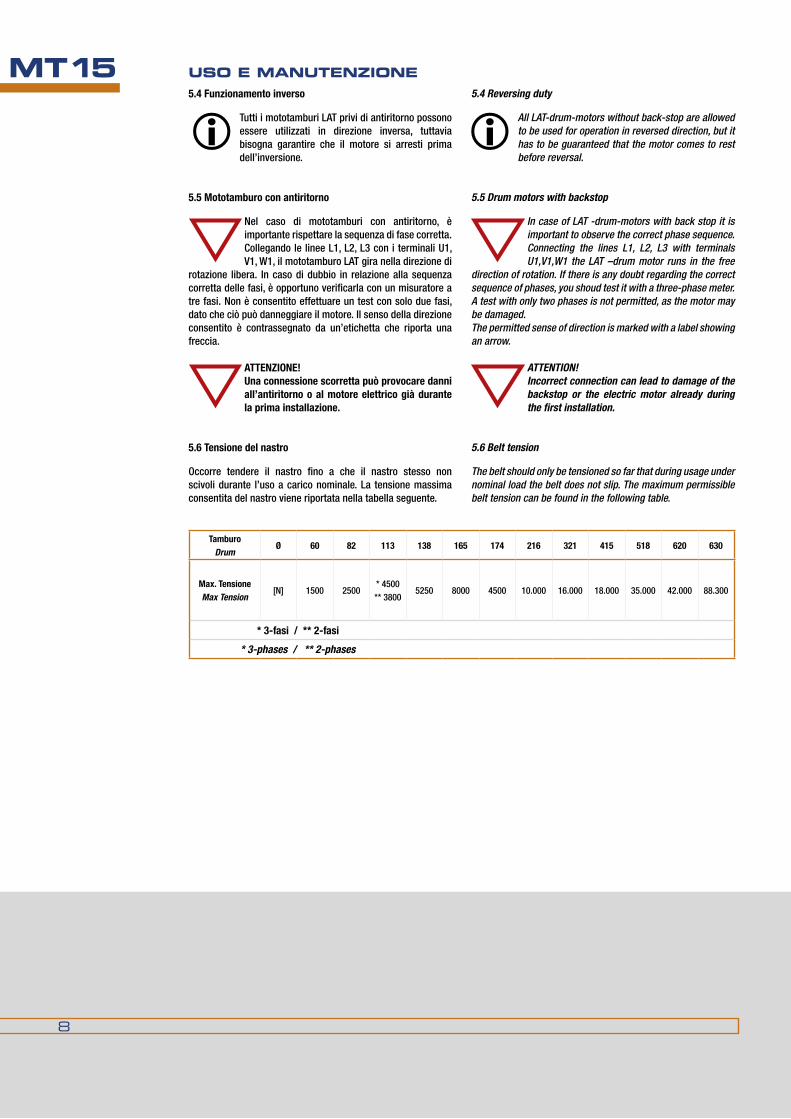
8
MT15 USO E MANUTENzIONE
Tamburo Drum
Ø 60 82 113 138 165 174 216 321 415 518 620 630
Max. TensioneMax Tension
[n] 1500 2500* 4500 ** 3800
5250 8000 4500 10.000 16.000 18.000 35.000 42.000 88.300
* 3-fasi / ** 2-fasi
* 3-phases / ** 2-phases
5.4 Reversing duty
All LAT-drum-motors without back-stop are allowed to be used for operation in reversed direction, but it has to be guaranteed that the motor comes to rest before reversal.
5.5 Drum motors with backstop
In case of LAT -drum-motors with back stop it is important to observe the correct phase sequence. Connecting the lines L1, L2, L3 with terminals u1,V1,W1 the LAT –drum motor runs in the free
direction of rotation. If there is any doubt regarding the correct sequence of phases, you shoud test it with a three-phase meter. A test with only two phases is not permitted, as the motor may be damaged.The permitted sense of direction is marked with a label showing an arrow.
ATTENTION!Incorrect connection can lead to damage of the backstop or the electric motor already during the first installation.
5.6 Belt tension
The belt should only be tensioned so far that during usage under nominal load the belt does not slip. The maximum permissible belt tension can be found in the following table.
5.4Funzionamentoinverso
Tutti i mototamburi LAT privi di antiritorno possono essere utilizzati in direzione inversa, tuttavia bisogna garantire che il motore si arresti prima dell’inversione.
5.5 Mototamburo con antiritorno
nel caso di mototamburi con antiritorno, è importante rispettare la sequenza di fase corretta. Collegando le linee L1, L2, L3 con i terminali u1, V1, W1, il mototamburo LAT gira nella direzione di
rotazione libera. In caso di dubbio in relazione alla sequenza corretta delle fasi, è opportuno verificarla con un misuratore a tre fasi. non è consentito effettuare un test con solo due fasi, dato che ciò può danneggiare il motore. Il senso della direzione consentito è contrassegnato da un’etichetta che riporta una freccia.
ATTENzIONE!Unaconnessionescorrettapuòprovocaredanniall’antiritorno o al motore elettrico già durante la prima installazione.
5.6 Tensione del nastro
Occorre tendere il nastro fino a che il nastro stesso non scivoli durante l’uso a carico nominale. La tensione massima consentita del nastro viene riportata nella tabella seguente.
9
MT15OPERATING INSTRUCTIONS6. ELECTRICAL CONNECTION OF A LAT-DRUM MOTOR
Before working on the drum motor, disconnect fully from all mains supplies.
Cables must be checked for possible damage.
Connection may only be performed by qualified personnel.
All relevant regulations in the area of electrical engineering must be observed during all work.
The user is liable for all accidents or costs resulting from none observtion of these rules.
6.1General
Squirrel cage rotor motors are started either direct or with star delta starting. Before LAT drum motors are finally put into operation, they are to undergo a trail start under no-load conditions. In cable design, the wires have either an alphanumeric or colour coding. The grounding connection is always green-yellow striped.
Before connecting the motor it must be assured that the mains voltage available corresponds with the voltage given on the name plate.
The connection of the motor must be observed.
A correct phase sequence L1 L2 L3 (R-S-T) and connection according to the given connection diagram, causes the motor to rotate clockwise when looking at the side of the electrical connection (cable or terminal box). Counter clockwise rotation is achieved by interchanging two phases.
The voltage 230/400 V ±5% given on the name plate means that the motor can be driven with 230 V ±5% in delta and with 400 V ±5% in star connection
6.2 Motor Types
6.2.1 Drum -motors with single speeddependent on the supplied design, drum-motors with single speed have to be connected according to the wiring diagram supplied.
6.2.2 Drum motors with double speedsfor drives which require two different non-variable speeds, the motors will be supplied in a pole changing version. The standard design of pole changing motors is calculated for direct starting conditions.Motors with a ratio of speed 1:2 are executed with tapped wound winding (dahlander).
6. CONNESSIONE ELETTRICA DI UN MOTOTAMBURO LAT
Prima di azionare il mototamburo, scollegarlo completamente da tutte le fonti di alimentazione.
occorre controllare se sono presenti eventualidannineicavi.
La connessione può essere effettuata solo da personale qualificato.
Durantetutteleoperazioni,occorrerispettaretuttelenormativeapplicabili del settore dell’ingegneria elettrica.
La responsabilità di tutti gli incidenti e tutti i costi derivanti dal mancato rispetto di queste normative sono a carico dell’utente.
6.1Generalità
I motori dei rotori a gabbia di scoiattolo si avviano o direttamente o mediante avviamento a stella delta. I mototamburi LAT devono effettuare un avvio in condizioni di assenza di carico prima di essere resi operativi. nel design del cavo, i fili hanno un codice alfanumerico o mediante colori. La connessione a terra è sempre a strisce verde-giallo.
Prima di collegare il motore, occorre assicurarsi che la tensione di alimentazione disponibile corrisponda alla tensione riportata sulla targhetta.
Occorre rispettare la connessione del motore.
una sequenza di fase corretta L1 L2 L3 (r-S-T) e la connessione secondo il diagramma della connessione in dotazione fa sì che il motore ruoti in senso orario guardando il lato della connessione elettrica (cavo o cassetta terminale). Si ottiene una rotazione antioraria scambiando due fasi.
La tensione 230/400 V ± 5% riportata sulla targhetta significa che è possibile azionare il motore con 230 V ± 5% in delta e con 400 V ± 5% in connessione stella
6.2. Tipi di motore
6.2.1MototamburiaunavelocitàA seconda del design in dotazione, occorre connettere i mototamburi a velocità singola secondo il diagramma dei cavi in dotazione.
6.2.2MototamburiadoppiavelocitàPer azionamenti che richiedono due diverse velocità non variabili, i motori vengono forniti in versione a cambio di polo. Il design standard dei motori a cambio di polo è calcolato per le condizioni di partenza dirette.I motori con rapporto di velocità di 1:2 vengono azionati con avvolgimento collegato (dahlander).

10
MT15 USO E MANUTENzIONE6.3 versioni a connessione
6.3.1.1 Blocco terminale e direzione della rotazione I mototamburi LAT con cassetta terminale sono dotati di quadro terminale con sei o otto bulloni terminali, che corrispondono allo standard Ce-34-8.Se il motore viene collegato secondo il diagramma dei cavi in dotazione, ruota in senso orario guardando il lato della connessione elettrica. Se il motore è dotato di ulteriori accessori (per esempio, termostati avvolgibili o freno), le connessioni risultano sui terminali a striscia contrassegnati.
6.3.1.2 Connessione a terra con cassetta terminaleIl terminale a terra è situato su una parte soprelevata all’interno della cassetta terminale. È contrassegnato dal simbolo .Come equipaggiamento speciale, è possibile fornire nell’alloggiamento stesso un secondo terminale a terra, anch’esso contrassegnato in maniera identica.
La connessione a terra deve essere effettuata con almeno la stessa sezione trasversale del cavo, come i cavi per l’alimentazione.
6.3.1.3 MaterialeIl materiale standard per le cassette terminali è lega di alluminio, ghisa GG25 oppure plastica nel contenitore IP 65.Il premistoppa o allenta tensione del cavo è ubicato verso il basso, guardando la cassetta terminale.
6.4 Freno
durante l’azionamento dei mototamburi con il freno, occorre osservare che il freno deve essere disattivato collegando la tensione della bobina riportata sulla targhetta prima di avviare il motore. In caso contrario, è possibile danneggiare il freno.
7. FUNzIONAMENTO DEI MOTOTAMBURI LAT
7.1 Aumento di temperatura / Classe di isolamentoIl sistema di isolamento dei motori standard corrisponde alla classe di isolamento f secondo Vde 0503 (IeC34 Teil 1, IeC86). Per una temperatura di raffreddamento di 40°C, l’aumento ammissibile di temperatura dell’avvolgimento è 155°C (105 K).
7.2 Funzionamento con nastro trasportatoreQuando il mototamburo viene montato su un nastro trasportatore, si deve osservare che non siano presenti particelle del matreiale trasportato o parti estranee tra il nastro ed il tamburo. Se ciò avviene è possibile che ne risultino danneggiati il tamburo, il nastro o il rivestimento in gomma. Qualora il mototamburo si blocchi, il motore elettrico o la scatola del cambio possono risultarne distrutti. Per evitare questa eventualità, è possibile avvalersi di apparecchiature deflettenti e protezioni adeguate.
6.3 Connection Versions
6.3.1.1 Terminal block and direction of rotationThe LAT-drum motors with terminal box are equipped with a terminal board with either six or eight terminal bolts, which correspond to the standard EC-34-8.If the motor is connected according to the given wiring diagramm, it rotates clockwise when facing the side of the electrical connection.If the motor is equipped with additional accessories (e.g. winding thermostats or a brake), the connection results on the marked strip-terminals.
6.3.1.2GroundingwithTerminalboxThe grounding terminal is situated on an elevated portion within the terminal box. It is marked with the symbol . As special equipment a second grounding terminal can be provided on the housing itself. This is also marked in the same way.
The grounding has to be executed with at least the same cable cross-section as the cables for the powersupply.
6.3.1.3 MaterialThe standard material for the terminal boxes is either aluminum-alloy, cast-iron GG25 or plastic in enclosure IP 65.The cable gland or strain relief is positioned downwards when looking at the terminal box.
6.4 Brake
during operation of drum-motors with brake it has to be observed that the brake has to be disengaged by connecting the coil voltage given on the name plate before starting of the motor. otherwise damage to the brake may result.
7. OPERATION OF LAT-DRUM MOTORS
7.1 Temperature rise / Insulation ClassThe insulation system of the standard motors corresponds to insulation class f according to VdE 0530 (IEC34 Teil 1, IEC86). for a cooling temperature of 40°C, the permissible termperature rise of the win ding is 155°C (105 K).
7.2 Operation with conveyor beltShould the drum-motor be operated in connection with a conveyor-belt, it must be obseved, that no transport particles or obstacles are present between the belt and the drum. If this occurs either the drum, the belt or the rubber-lining may be damaged. Should then the drum motor block, the electric motor or gearbox can be destroyed. To avoid this deflecting equipment and preventive mechanisms can be used.

11
MT15OPERATING INSTRUCTIONS
Dati tecnici (linee guida) / Technicaldata(Guidelines)
ISo-VGviscosità mm2/s (cST) /
Viscosity mm²/s (cST)
Punto d’infiammabilità
Flash Point
Temperatura di colata
Pour Point
Olio secondo la norma
Gearoilacc.To
40°C 100C° °C °C DIN 51517 parte/part 3
100 102 11,3 240 -21 CLP 100
Tipidiolioconsigliatidifornitoridiversi/Recommended oil types of differing suppliers
FornitoreSupplier
FINA CASTROL BP ESSO MOBILOIL SHELL TEXACO DEA
Tipo / Type Giran Alpha energol nuto mobil-gear Omala meropa falcon
n 100 zn 100 Gr-XP100 h 100 627 100 100 CLP 100
8. MANUTENzIONE E ASSISTENzA
un’attenta manutenzione e assistenza, secondo le nostre raccomandazioni, sono requisiti fondamentali per garantire la durata del mototamburo.Occorre effettuare operazioni di manutenzione scrupolose agli intervalli specificati, controlli di minore entità ogni qualvolta sia possibile, ma per lo meno secondo gli intervalli riportati.
8.1 PuliziaSolo i motori con protezioni a labirinto e tenute a labbro possono essere puliti con apparecchi di pulizia ad alta pressione. Tutti gli altri motori devono essere puliti senza applicare pressione.
8.2 Lubrificazione / sostituzione dell’olio8.2.1 Lubrificazionenon è necessario ingrassare i cuscinetti a sfere i cuscinetti a rullo utilizzati nei mototamburi LAT.
8.2.2 Sostituzione dell’olioTutti i mototamburi LAT vengono forniti con la quantità di olio necessaria per il corretto funzionamento. Il primo riempimento d’olio in fabbrica rispetta le seguenti specifiche tecniche: 100 cST / 40°C o 8° engler / 50 °C, la temperatura di colata è 20°C.L’olio è adatto per temperature ambiente da -20°C a +50°C.
Qualorasianoutilizzatialtritipidiolio,verificarechel’oliononcontengaadditivichepotrebberocompromettere l’isolamento delle spire di avvolgimento.
Inoltre, NON può essere usato alcun tipo di olio che comprenda grafite, solfuro di molibdeno o altre sostanze conduttrici, dato che ciò danneggerebbe il sistema di isolamento del motore.
8. MAINTENANCE AND CARE
Careful maintenance and care according to our advice is the basis for a long life of the drum-motor.
Extensive maintenance work has to be executed within the given intervals, smaller check-ups whenever possible but at the latest to the above mentioned interval periods.
8.1 CleaningWhen cleaning the drum-motor it has to be observed that only motors with labyrinth seals und V-ring seals are allowed to be cleaned with high pressure cleaning equipment. All other motors have to be cleaned without pressure application.
8.2 Lubrication / Oil Change8.2.1 LubricationGreasing of the ball-bearings or roller-bearings used within the LAT-drum-motors is not required.
8.2.2 Oil ChangeAll LAT-drum-motors are supplied with the quantity of oil necessary for correct operation. The primery oilfilling at the factory complies with the following technical specifications: 100 cST / 40°C or 8° Engler / 50°C, the pourpoint is -20°C.´The oil is suitable for ambient temperatures from -20°C up to +50°C.
Should other types of oil be used, please verify that the oil has no additives that could affect the insulation of the winding wires in a harmful way.Furthermore NO oil types which include
substances like graphite, molybdenum-sulfide or other conductive agents may be used, as the insulation system of the motor will be damaged.

12
MT15 USO E MANUTENzIONE
Occorre applicare un metodo ecocompatibile per smaltire l’olio usato.
durante la sostituzione dell’olio, occorre accertarsi che l’olio non contamini il pavimento o penetri il terreno avvalendosi di speciali vassoi di raccolta. Qualora si verificasse una fuga d’olio, occorre rimuoverlo immediatamente con una sostanza legante l’olio in maniera ecocompatibile. L’olio, la sostanza legante l’olio e il terreno inquinato devono essere smaltiti in maniera professionale.
An environmentally compatipble method of disposal of used oil is to be observed.
When changing the oil it has to be ensured that no oil contaminates the floor or penetrates the earth by use of special collecting trays. Should oil escape it must be removed immediately with an oil binding agent in an environmentally compatible way. The oil, oil-binding agents and polluted soil must be disposed of professionally.
The first oil change is recommended after 200 to 300 operation hours, thereafter every 10.000 operating hours.on the flange of the drum-moter are two oil drain
plugs, facing the side of the electrical connection.The two plugs have to be removed during oil changing and the drum has to be turned so long that the outer thread reaches the bottom position, to achive a free run out of the old used oil.
aCHTunG: it is to be observed that the marking „top“ onthe connection side never shows downwards otherwise the cooling / lubrication is no longer guaranteed.
Si consiglia di effettuare la prima sostituzione dell’olio dopo 200-300 ore di funzionamento e successivamente ogni 10.000 ore.Sulla flangia del mototamburo si trovano due spine
di scarico, rivolte verso la connessione elettrica.durante la sostituzione dell’olio occorre rimuovere le due spine ed il tamburo deve essere girato, di modo che il filetto esterno raggiunga la posizione di fondo, al fine di far uscire liberamente l’olio usato.
ATTENzIONE! Occorre accertarsi che il segno “alto” sul lato dellaconnessionenonpuntimaiversoilbasso,altrimentinonè più garantito il raffreddamento / la lubrificazione.
Tipo/Type Quantitàdiolionecessariainlitri–installazioneorizzontale/Necessary oil quantity in litre – horizontal installation
L [mm] 300 350 400 450 500 550 600 650 700 750 800 850 900 950 1000 1050 1100 1150 1200 1250 1300 1350
60.1 0,10 0,14 0,17 0,21 0,24 0,28 0,31 0,35 0,38 0,42 0,45 0,49 0,52 0,56 0,59 0,63 0,66 0,70 0,73 0,77 0,80
80.1 0,20 0,24 0,28 0,32 0,36 0,40 0,44 0,48 0,52 0,56 0,60 0,64 0,68 0,72 0,76 0,80 0,84 0,88 0,92 0,96 1,00
82.1 A richiesta / on Request
110.1 0,30 0,38 0,47 0,55 0,64 0,72 0,80 0,89 0,97 1,06 1,14 1,22 1,31 1,39 1,48 1,56 1,64 1,73 1,81 1,90 1,98 2,06
113.1 0,30 0,40 0,50 0,60 0,70 0,80 0,90 1,00 1,10 1,20 1,30 1,40 1,50 1,60 1,70 1,80 1,90 2,00 2,10 2,20 2,30 2,40
165.0 0,90 1,10 1,30 1,50 1,70 2,00 2,20 2,40 2,60 2,80 3,10 3,30 3,50 3,70 3,90 4,20 4,40 4,60 4,80 5,00
174.0 1,50 1,80 2,00 2,30 2,50 2,80 3,00 3,30 3,50 3,80 4,00 4,30 4,50 4,80 5,00 5,30 5,50 5,80 6,00
174.1 2,30 2,60 2,80 3,10 3,30 3,60 3,80 4,10 4,30 4,60 4,80 5,10 5,30 5,60 5,80 6,10 6,30 6,60 6,80 7,10
216.0 4,10 4,50 5,00 5,40 5,90 6,30 6,80 7,20 7,70 8,10 8,60 9,00 9,50 9,90 10,40 10,80 12,20 13,50 14,90 16,20
216.1 3,60 4,10 4,50 5,00 5,40 5,90 6,30 6,80 7,20 7,70 8,10 8,60 9,00 9,50 9,90 10,40 10,80 11,30 11,70 12,20
321.0 10,80 12,60 14,40 16,20 17,10 18,00 18,90 20,30 21,60 22,50 23,40 24,80 25,70 27,00 29,30 31,50 33,80 36,00
321.1 9,90 11,30 11,70 13,10 14,40 15,80 17,10 18,50 19,80 21,20 22,50 23,00 24,30 27,00 29,30 31,50 33,80 36,00
415.0 21,20 22,80 24,40 26,00 27,60 29,20 30,80 32,40 34,00 35,60 37,20 38,80 40,40 42,00 43,60 45,20
415.1 16,20 17,80 19,40 21,00 22,60 24,20 25,80 27,40 29,00 30,60 32,20 33,80 35,40 37,00 38,60 40,20
518.0 36,90 40,90 45,00 49,10 53,10 57,20 61,20 65,30 69,30 73,40 77,40 81,50 85,50
518.1 27,00 30,60 34,20 37,80 40,50 44,10 47,70 51,30 54,00 60,80 67,50 72,10 76,50
620.0 90,00 93,60 97,20 100,80 104,40 108,00 112,00 116,00 119,00
630 A richiesta / on Request

13
MT15OPERATING INSTRUCTIONS8.3 Sostituzione dei cuscinetti
La durata dei cuscinetti dipende molto dalle condi-zioni operative. Pertanto è molto difficile calcolarla in maniera affidabile. Se le condizioni operative sono specificate dall’operatore, è possibile calco-
lare la durata del cuscinetto ed indicarla sulla piastra di valuta-zione. Se non vengono fornite informazioni, le modifiche negli schemi di vibrazioni e rumore possono segnalare che è neces-sario provvedere all’immediata sostituzione del cuscinetto.
8.4 Protezioni a labirinto
Occorre controllare visivamente la presenza di possibili difetti sulle protezioni a labirinto a brevi intervalli di tempo o almeno una volta al mese. È necessario controllare le tenute a
labbro rivoltandole verso l’esterno e rimuovendo depositi o contaminazioni con una spazzola o con un panno.Ogni 2000 ore di funzionamento, oppure almeno una volta all’anno, occorre pulire completamente le protezioni a labirinto. Per fare ciò occorre svitare il tappo protettivo e rimuovere la tenuta a labbro dall’albero.durante questa procedura di pulizia, occorre verificare che le condizioni delle protezioni siano soddisfacenti, altrimenti non è più garantita la corretta funzionalità del sigillo.
8.5 Freno
La polvere del freno interno dei mototamburi LAT viene rimossa automaticamente ad ogni cambio d'olio.
8.6Rivestimentoingomma
Occorre controllare visivamente i mototamburi con rivestimento in gomma a brevi intervalli di tempo per garantire che il rivestimento stesso non sia danneggiato. un rivestimento danneggiato
provoca squilibrio durante il funzionamento del tamburo e può danneggiare i cuscinetti.
8.3 Replacing bearings
The bearing life depends very much on the operating conditions. It is therefore very difficult to calculate it reliably. If the operating conditions are specified by the operator, the bearing life can be calculated and
indicated on the rating plate. If no information is given, changes in the vibration and noise pattern can serve as an indication that an immediate bearing replacement is necessary.
8.4 Labyrinth Seals
Labyrinth seals have to be checked visually for possible defects at short intervalls or at least once a month. It is also necessary to check the V-rings by means of turning inside out and removing
deposits or contaminations with a brush or cloth.Every 2000 operating hours, or at least once a year, the labyrinth-seals have to be completely cleaned. To do this you have to unscrew the protective cap and remove the V-ring from the shaft.during this cleaning procedure the satisfactory conditions of the seals has to be checked, otherwise the correct functionality of the seal is no longer guaranteed.
8.5 Brake
The brake dust of the internal brake of LAT-drum motors is removed automatically during every oil change.
8.6 Rubber lining
drum-motors with rubber linings have to be visually checked at short intervalls to ensure there is no damage to the rubber lining. damage of the lining causes unbalance during operation of the drum and
may lead to a bearing failure.
9. SOPPRESSIONE DELL’INTERFERENzA DELLA FReQUenzaRaDIo
Il telaio dei motori trifasici a gabbia di scoiattolo è stato concepito in maniera tale da tenere le fonti elettromagnetiche di disturbo ad una distanza tale che non avviene alcuna effettiva penetrazione nel circuito magnetico che influenzi il normale funzionamento del motore.Il normale motore trifasico a gabbia di scoiattolo non produce frequenze radio, ma è possibile che i conduttori utilizzati per connettere il motore all’alimentazione (interruttori) richiedano ulteriori componenti per eliminare le interferenze.
9.radioFreQuenCyinTerFerenCeSUPPRESSION
The frame of the three-phase squirrel-cage motors are designed in such a way that electromagnetic disturbance sources are kept at such a distance that no real penetration into the magnetic circuit takes place to disturb the normal operation of the motor.The normal three-phase squirrel-cage motor does not produce radio frequencies. But the conducters which are used to connect the motor to the mains (circuitbreakers) may need additinal components to clear interferences.

14
MT15 USO E MANUTENzIONE
11.GaRanzIe
Tutti i mototamburi che vengono restituiti durante il periodo di garanzia da noi accordato verranno riparati gratuitamente, qualora vi sia un danno o un guasto la cui responsabilità è ascrivibile al fabbricante.
Non si accetta alcuna responsabilità per danni o malfunzionamenti dovuti a:
• Mancatorispettodelleinformazioniedelleistruzionifornite nel presente manuale di istruzioni, per esempio tensione del nastro scorretta, connessioni elettriche errate, manutenzione scorretta o assente o uso disattento.
• Conduttore motore selezionato e tarato in maniera scorretta o connessioni difettose dei contatti di protezione dell’avvolgimento.
•Surriscaldamentodelmotore.
•Funzionamento a velocità inversa senza rispettare la posizione di arresto del motore.
11. WARRANTIES
All drum-motors which are returned during the guarantee period agreed to by us will be repaired on a no charge basis, if there is a damage or failure the factory itself is liable for.
We accept no liability for any damage or malfunction resulting from:
•Non observance of the information and rules given in this maintenance instruction, e.g. wrong belt tension, wrong electrical connections, not correct or missing maintenance or careful handling.
•Incorrectselectedandcalibratedmotor-conductororfaulty connections of the winding protection contacts.
•Overloadingofthemotor.
•Operation on reversed speed without observing stopping position of the motor.
10 PROTEzIONE DEL MOTORE
L’avvolgimento dei motori elettrici deve essere protetto dalla sovracorrente e da eccessivi aumenti di temperatura. I dispositivi di protezione in dotazione ai mototamburi garantiscono la sicurezza di funzionamento dal sovraccarico con deviazioni che avvengono lentamente. Occorre scegliere il tipo adatto di sistema di protezione per il motore a seconda dei tipi di operazioni, come segue:Linee guida per la posizione dei diversi sistemi di protezione (la dotazione del sistema è opzionale)PTO o PTf = (termostati bimetallici) da incorporare nel circuito ausiliarePTO (apertura WT) = il termostato apre i contatti alla temperatura predeterminataPTf (chiusura WT) = il termostato chiude i contatti alla temperatura predeterminataPTC (termistore) = da armonizzare con il circuito ausiliare lungo l’unità di controllo.
Termistore: resistore semiconduttore termicamente sensibile, la cui funzione primaria è di mettere in evidenza un considerevole cambiamento di resistenza elettrica che provoca l’attivazione del controllore.
Allarme e spegnimento
Se vengono utilizzati doppi dispositivi di protezione (con diverse gamme di temperature nominali), è possibile che il primo dispositivo assuma la funzione di allarme (in maniera acustica oppure ottica, senza
interrompere il circuito di linea), mentre il secondo dispositivo di protezione può essere utilizzato per spegnere il circuito di linea (tutta l'alimentazione del motore in questione verrà interrotta).
10. MOTOR PROTECTION
The winding of electrical motors has to be protected against over-current and non permissible temperature rise. The protection devices provided for the LAT-drum-motors guarantee the safe protection against overload with slowly occuring deviations. The suitable type of protection system for the motor should be selected according to the duty-types given as follows:Guidelines for the position of different protection systems (supply of system is optional)PTo or PTf = (bimetallic thermostats ) to be incorporated into the auxiliary circuitPTo (WT-opener) = The thermostat opens the contacts at the predetermined temperaturePTf (WT-closer) = The thermostat closes the contacts at the predetermined temperaturePTC (Thermistor)= to be arranged within the auxiliary circuit along with the control unit.
Thermistor: A thermally sensitive semi-conductor resistor, whose primary function is to exhibit an considerable change in electrical resistance causung the controller to activate.
Warning and Switch-Off
If there are dual protection devices employed (with different nominal duty temperature ranges) the first device may take over the warning operation (in an acoustic or optical manner, without interrupting the
line circuit) whereas the second protection device can be used to switch off the line circuit (all power supply for the concerned drive will be stopped).

15
MT15OPERATING INSTRUCTIONS
DICHIARAzIONE DEL FABBRICANTE
In ottemperanza alle Linee Guida sui macchinari Cee 98/27/eG appendice II b, con la presente dichiariamo che questi componenti descritti nel catalogo Am-10.1 sono stati concepiti per essere installati in macchinari la cui messa in funzione è vietata fintanto che non venga accertato che il macchinario e tutti i componenti compresi al suo interno rispettino le condizioni delle Linee guida Cee 98/37/eG.
La marcatura Ce si riferisce al rispetto delle linee guida sulla bassa tensione 2006/95/eWG e alle linee guida emC 89/336/eWG.Con la presente dichiarazione, sono stati presi in considerazione in tutto o in parte tutti gli standard armonizzati pubblicati dalla Commissione europea nella Gazzetta ufficiale delle Comunità europee applicabili ai nostri prodotti.
In particolare:- dIn en ISO 12100-1: Parte 1: Terminologia di base, metodologia- dIn en ISO 12100-2: Parte 2: Principi tecnici- dIn en 60529: Classe di protezione con l’alloggiamento (codice IP)- dIn en 60034-1: Parte 1: fondamentali e requisiti- dIn en 60034-5: Parte 5: Protezione per sicurezza del design
MANUFACTURER DECLARATION
In terms of the EEC Machine Guidelines 98/27/EG Appendix II B we herewith declare that the component included in catalogue AM-10.1 are designed for installation in machines whose commissioning is forbidden until it has been ascertained that the machine and all components included within meet the conditions of the EEC Guidelines 98/37/EG.
The CE marking refers to the adherence of the low voltage guidelines 2006/95/EWG and the EMC-Guidelines 89/336/EWG.With this declaration, all harmonised standards published by the EC commission in the official journal of the European Commuities applicable for our products have been totally or partly considered.
These are especially:- dIN EN ISo 12100-1: Part 1: Basic terminology, methodology- dIN EN ISo 12100-2: Part 2: Technical principles- dIN EN 60529: Protection class by housing (IP)- dIN EN 60034-1: Part 1: fundamentals and requirements- dIN EN 60034-5: Part 5: Protection by design safety
• Azionamento del motore nella direzione sbagliata contro l’antiritorno.
• Cambiamento delle condizioni operative contrario alle presenti istruzioni operative.
•Modifiche delle unità motore ed ausiliarie senza conferma scritta da parte del fabbricante.
•Riparazioneemodificadeimotorisenzaconfermascrittada parte del fabbricante.
•Gestionescorrettaedanniintenzionali.
•Normalelogoriodeicomponenti.
La nostra garanzia si limita unicamente al prodotto che forniamo. non accettiamo rivendicazioni dovute allo smontaggio e almontaggio di unità, a trasporto, confezionamento o arresto del macchinario.
In caso di ulteriori richieste o di ordinazioni di pezzi di ricambio, si prega di precisare il numero del motore. Se sulla targhetta non è riportato alcun numero di motore, è possibile leggere il numero stesso sulla facciata dell’estensione a stelo.
Tutti i dati tecnici delle presenti istruzioni sono soggette a modifiche e, quindi, non comportano alcun obbligo.
•Running the motor in the wrong direction against locked back-stop.
•Changingofoperationconditionagainstthegivenoperating instructions
• Changes on motor and auxiliary units without written confirmation by the manufacturer.
• Repair and modification on motors without written confirmation by the manufacturer.
•Wilfulmishandlinganddamaging.
•Normalwearandtearofcomponents
Our guarantee promise is only bound to failures on our supplied product.We accept by no means charges due to disassembling and assembling of units, transport, package or shutdown of machinery.
In case of further inquiries or ordering of spare parts, please indicate the motor number. If there is no motor number shown on the name plate, the number can be read on the face of the shaft extension.
All given technical data in this operating instruction are liable to changes and therefore without obligation.

16
MT15 USO E MANUTENzIONE
Tutte le dimensioni sono soggette a tolleranze di lavorazione e benché i disegni e le illustrazioni siano fedeli, non sono tuttavia impegnativi. La duGOmruLLI si riserva di modificare i propri prodotti senza preavviso.La riproduzione anche parziale delle figure e del testo è vietata a norma del C.C. e della legge sui diritti d’autore.
All dimensions are subject to machining tolerances, and although drawings and illustrations are exact, they place the manufacturer under no obligation whatsoever.duGoMRuLLI reserves the right to modify their products at any time without notice. Even a part reproduction of present catalogue’s illustrations, and text, is forbidden.


DUgOMRULLI SRLVia Ippolito Nievo, 8 | 40069 Zola Predosa (Bo) | Tel. 051.755406 Fax 051.758989 | [email protected] | www.dugomrulli.it
MCPRODUCER
UN’AZIENDA IN CONTINUO MOVIMENTO ATTENTA ALLE VOSTRE ESIgENZE E ALL’EVOLUZIONE DEL MERCATO.
Codice QR
Legenda peR Revisioni CataLogoe CapitoLi inteRni
Rev. 01/1301 - numero progressivo revisione
2013 - anno di revisione