Embed Size (px)
DESCRIPTION
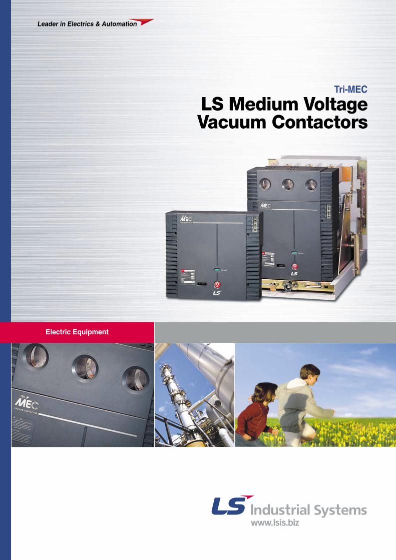
Tri-MEC Electric Equipment Leader in Electrics & Automation Customer satisfaction through quality and service- LS medium voltage vacuum contactors LS medium voltage vacuum contactors using LS vacuum interrupters manufactured with worldclass technology are type tested in LS PT & T that is accredited high power test lab by worldclass KOLAS.
Citation preview
Leader in Electrics & Automation
Electric Equipment
Tri-MEC
LS Medium Voltage Vacuum Contactors
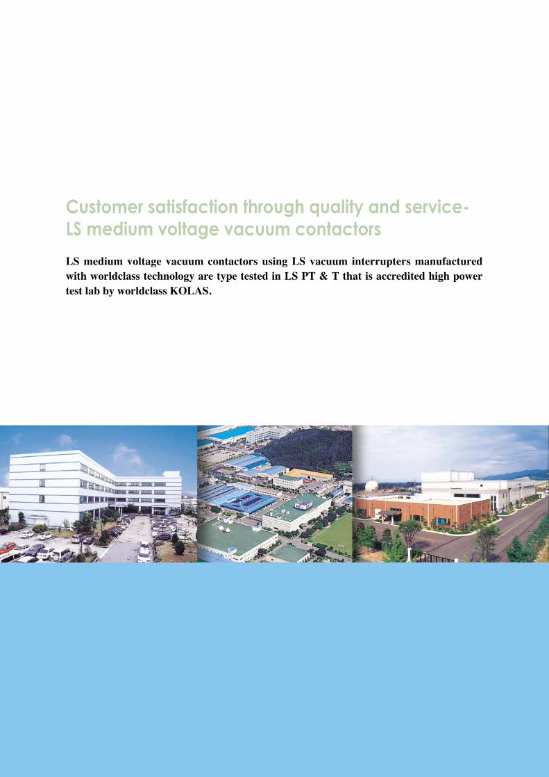
Customer satisfaction through quality and service-LS medium voltage vacuum contactors
LS medium voltage vacuum contactors using LS vacuum interrupters manufacturedwith worldclass technology are type tested in LS PT & T that is accredited high powertest lab by worldclass KOLAS.

Contents
Features 4
Technical data 10
Ordering information 12
External view 14
Safety components 15
Internal structure 16
Vacuum interrupters 17
Accessories 18
Drawing operations 19
Electrical circuit diagram 20
Internal connection diagrams 22
External dimensions 24
Selection tables 28
Power fuse 30
Power fuse selection guides 31
Coordination graph 32
Operation curves 34
General description
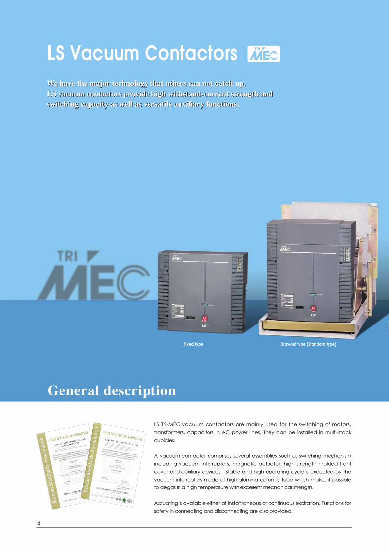
We have the major technology that others can not catch up.LS vacuum contactors provide high withstand-current strength and switching capacity as well as versatile auxiliary functions.
Fixed type Drawout type (Standard type)
LS Tri-MEC vacuum contactors are mainly used for the switching of motors,
transformers, capacitors in AC power lines. They can be installed in multi-stack
cubicles.
A vacuum contactor comprises several assemblies such as switching mechanism
including vacuum interrupters, magnetic actuator, high strength molded front
cover and auxiliary devices. Stable and high operating cycle is executed by the
vacuum interrupters made of high alumina ceramic tube which makes it possible
to degas in a high temperature with excellent mechanical strength.
Actuating is available either at instantaneous or continuous excitation. Functions for
safety in connecting and disconnecting are also provided.
LS Vacuum Contactors
4
We have the major technology that others can not catch up.LS vacuum contactors provide high withstand-current strength and switching capacity as well as versatile auxiliary functions.

Direct-drawout type - for MCSG Fuse connectable type (Standard type)
E-Class Cradle F2-Class Cradle G-Class Cradle
Fuse connectable type (Direct-drawout type)
Operation conditionsAmbient temperature : -5 to 40℃
Maximum temperature of 24-hour mean : 35 ℃
Altitude : 1000m
Humidity : 24-hour measured average - max. 95% RH
1 month measured average - max. 90% RH
Applied standardsIEC Pub. 60470, IEC 60282-1, JEM 1167, KEMC 1126
5
[ 40kA ]Power fused type vacuum contactors, in-house tested according to IEC 60282-1,
can provide short-circuit protection up to 40kA.
Short-circuit protection
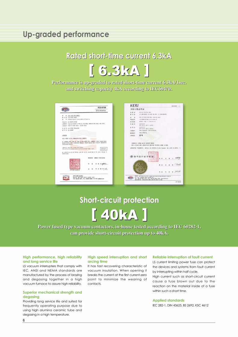
High performance, high reliabilityand long service lifeLS vacuum interrupters that comply withIEC, ANSI and NEMA standards aremanufactured by the process of brazingand degasing together in a highvacuum furnace to assure high reliability.
Superior mechanical strength anddegasingProviding long service life and suited forfrequently operating purpose due tousing high alumina ceramic tube anddegasing in a high temperature.
High speed interruption and shortarcing timeIt has fast recovering characteristic ofvacuum insulation. When opening itbreaks the current at the first current-zeropoint to minimize the wearing ofcontacts.
Reliable interruption of fault currentLS current limiting power fuse can protect
the devices and systems from fault current
by interrupting within half cycle.
High current such as short-circuit current
cause a fuse blown out due to the
reaction on the material inside of a fuse
within such a short time.
Applied standardsIEC 282-1, DIN 43625, BS 2692, KSC 4612
6
Up-graded performance
[ 6.3kA ]Performance is up-graded to rated short-time current 6.3kA/1sec.
and switching capacity 4kA according to IEC60470.
Rated short-time current 6.3kA
[ 6.3kA ]Performance is up-graded to rated short-time current 6.3kA/1sec.
and switching capacity 4kA according to IEC60470.
Rated short-time current 6.3kA
[ 40kA ]Power fused type vacuum contactors, in-house tested according to IEC 60282-1,
can provide short-circuit protection up to 40kA.
Short-circuit protection

7
Suitable for Metal CladSwitchgearThe structure of G type cradle unification
bushings and single-molded fuse-holder
barrier enables vacuum contactors to
build Metal Clad Switchgears.
Directly withdrawable equipmentThis enables the withdrawing of a
vacuum contactor from a panel without
opening a door to prevent any possibility
of electric shock.
Interlock For the safety of a operator interlock is
equipped as standard.
Auxiliary contactsAvailable up to 5NO+5NC.
Contactor over contactor arrangement
[ Safety ]LS Tri-MEC vacuum contactors provide several auxiliary functions
for safe and comfortable use.
[ Safety ]LS Tri-MEC vacuum contactors provide several auxiliary functions
for safe and comfortable use.
Personnel safety
■■Interlock button
■■Drawout cradle for MCSG
■■One-molded fuse holder
■■Fuse checher and micro switch
■■Unification bushing
■■Mechanical interlock type
■■Interlock button
■■Drawout cradle for MCSG
■■One-molded fuse holder
■■Fuse checher and micro switch
■■Unification bushing
■■Mechanical interlock type
Additional equipment
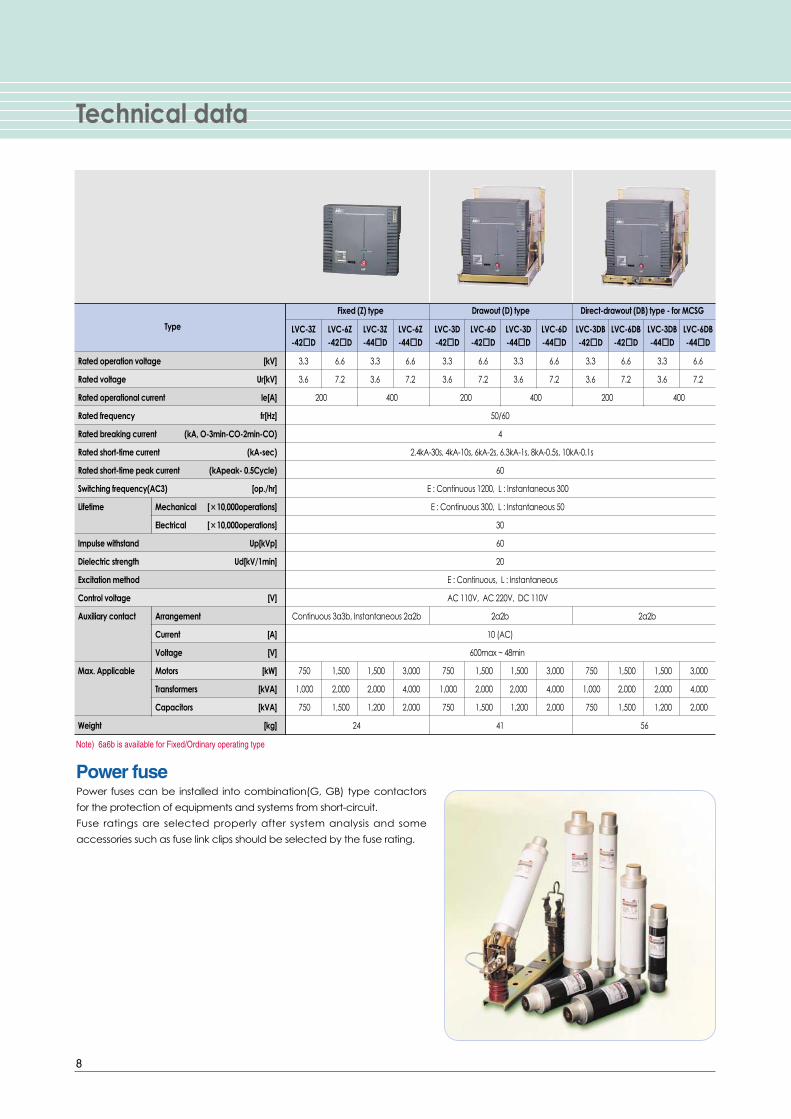
Technical data
8
Power fusePower fuses can be installed into combination(G, GB) type contactors
for the protection of equipments and systems from short-circuit.
Fuse ratings are selected properly after system analysis and some
accessories such as fuse link clips should be selected by the fuse rating.
Fixed (Z) type Drawout (D) type Direct-drawout (DB) type - for MCSG
Type LVC-3Z LVC-6Z LVC-3Z LVC-6Z LVC-3D LVC-6D LVC-3D LVC-6D LVC-3DB LVC-6DB LVC-3DB LVC-6DB-42��D -42��D -44��D -44��D -42��D -42��D -44��D -44��D -42��D -42��D -44��D -44��D
Rated operation voltage [kV] 3.3 6.6 3.3 6.6 3.3 6.6 3.3 6.6 3.3 6.6 3.3 6.6
Rated voltage Ur[kV] 3.6 7.2 3.6 7.2 3.6 7.2 3.6 7.2 3.6 7.2 3.6 7.2
Rated operational current le[A] 200 400 200 400 200 400
Rated frequency fr[Hz] 50/60
Rated breaking current (kA, O-3min-CO-2min-CO) 4
Rated short-time current (kA-sec) 2.4kA-30s, 4kA-10s, 6kA-2s, 6.3kA-1s, 8kA-0.5s, 10kA-0.1s
Rated short-time peak current (kApeak- 0.5Cycle) 60
Switching frequency(AC3) [op./hr] E : Continuous 1200, L : Instantaneous 300
Lifetime Mechanical [××10,000operations] E : Continuous 300, L : Instantaneous 50
Electrical [××10,000operations] 30
Impulse withstand Up[kVp] 60
Dielectric strength Ud[kV/1min] 20
Excitation method E : Continuous, L : Instantaneous
Control voltage [V] AC 110V, AC 220V, DC 110V
Auxiliary contact Arrangement Continuous 3a3b, Instantaneous 2a2b 2a2b 2a2b
Current [A] 10 (AC)
Voltage [V] 600max ~ 48min
Max. Applicable Motors [kW] 750 1,500 1,500 3,000 750 1,500 1,500 3,000 750 1,500 1,500 3,000
Transformers [kVA] 1,000 2,000 2,000 4,000 1,000 2,000 2,000 4,000 1,000 2,000 2,000 4,000
Capacitors [kVA] 750 1,500 1,200 2,000 750 1,500 1,200 2,000 750 1,500 1,200 2,000
Weight [kg] 24 41 56
Note) 6a6b is available for Fixed/Ordinary operating type
9
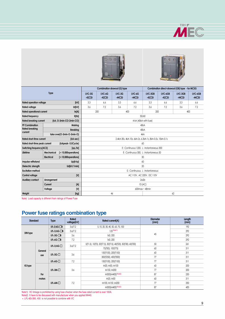
Standard Type Rated Rated current(A) Diameter Lengthvoltage(kV) (mm) (mm)
LFL-3/6G-��B 3.6/7.2 5, 10, 20, 30, 40, 50, 63, 75, 100 192
DIN typeLFL-3/6G-��B 3.6/7.2 125 Note1)
45292
LFL-3G-��B 3.6 160, 200 292
LFL-6G-��B 7.2 160, 200 292
LFL-3/6G-�� 3.6/7.25(T1.5), 10(T3), 20(T7.5), 30(T15), 40(T20), 50(T30), 60(T30) 50 261
75(T50), 100(T75) 60 311General
LFL-3G-�� 3.6150(T100), 200(T150) 60 311
use300(T250), 400(T300) 77 311
LFL-6G-�� 7.2 150(T100), 200(T150) 77 311
KS type M20, M50, M100 60 200
LFL-3M-�� 3.6 M150, M200 77 200
For M300(M400)Note2) 87 250
motors M20, M50 60 311
LFL-6M-�� 7.2 M100, M150 ,M200 77 350
M300(M400)Note2) 87 450
Note1) VC linkage is prohibited by using fuse checker when the fuse rated current is over 100A. Note2) It have to be discussed with manufacturer when you applied M440.� LFL-6G-300, 400 is not possible to combine with VC
Note) Load capacity is different from ratings of Power Fuse
Power fuse ratings combination type
Combination drawout (G) type Combination direct-drawout (GB) type - for MCSG
Type LVC-3G LVC-6G LVC-3G LVC-6G LVC-3GB LVC-6GB LVC-3GB LVC-6GB-42��D -42��D -44��D -44��D -42��D -42��D -44��D -44��D
Rated operation voltage [kV] 3.3 6.6 3.3 6.6 3.3 6.6 3.3 6.6
Rated voltage Ur[kV] 3.6 7.2 3.6 7.2 3.6 7.2 3.6 7.2
Rated operational current le[A] 200 400 200 400
Rated frequency fr[Hz] 50/60
Rated breaking current (kA, O-3min-CO-2min-CO) 4 kA (40kA with fuse)
PF Combination Making 40kARated breaking Breaking 40kAcurrent
take over(O-3min-O-3min-O) 4kA
Rated short-time current (kA-sec) 2.4kA-30s, 4kA-10s, 6kA-2s, 6.3kA-1s, 8kA-0.5s, 10kA-0.1s
Rated short-time peak current (kApeak- 0.5Cycle) 60
Switching frequency(AC3) [op./hr] E : Continuous 1200, L : Instantaneous 300
Lifetime Mechanical [××10,000operations] E : Continuous 300, L : Instantaneous 50
Electrical [××10,000operations] 30
Impulse withstand Up[kVp] 60
Dielectric strength Ud[kV/1min] 20
Excitation method E : Continuous, L : Instantaneous
Control voltage [V] AC 110V, AC 220V, DC 110V
Auxiliary contact Arrangement 2a2b
Current [A] 10 (AC)
Voltage [V] 600max ~ 48min
Weight [kg] 46 62

Ordering information
10
Installation
Z Fixed type
D Drawout type
G Combination drawout type(Fuse connectable)
DB Direct-drawout type(For MCSG)
Combination direct-
GB drawout type(Fuse connectable
and for MCSG)
Contactor
LS VacuumContactor
Rated voltage(kV)
3 3.6
6 7.2
Rated current(A)
2 200
4 400
Breaking current(kA)
4 4
Modification No.
D Tri-MEC
Control method
E Continuous excitation
L Instantaneousexcitation
Fuse checker
0 Without
1 With
PT
0 Without PT
1 1EA of 100Var
2 2EA of 100Var
3 1EA of 200Var
4 2EA of 200Var
Control voltage(V)
D1 DC 110
A1 AC 110
A2 AC 220
FUSE type
01 LFL-3/6G-5~60 L261-∅50
02 LFL-3M-20~100 L200-∅60
LFL-3/6G-75~100 L311-∅60
03 LFL-3G-150~200
LFL-6M-20~50
04 LFL-3M-150~200 L200-∅77
05LFL-3G-300~400 L311-∅77
LFL-6G-150~200
06 LFL-6M-100~200 L350-∅77
07 LFL-3M-300 L250-∅87
08 LFL-6M-300 L450-∅87
09 LFL-3/6G-5B~100B L258-∅45
10 LFL-3/6G-125B~200B L358-∅45
Contactor type
Position Switch
0 Without
1 With

11
Cradle
LS VacuumContactor
MechanicalInterlock
Vacuum Contactor(VC1)
Position Switch
PS1 1a1b
PS2 2a2b
Cradle Type
E E class
F F2 class (with shutter only)
G G class (with shutter and bushings)
B For MCSG
RatingsLS Cradle
Breaking current
4kA
Rated current
200/400A common
Rated voltage(kV)
3/6 3.6/ 7.2kVcommon 42
/44
Mechanical interlock type
32E LVC-3Z-42ED
34E LVC-3Z-44ED
62E LVC-6Z-42ED
64E LVC-6Z-44ED
32L LVC-3Z-42LD
34L LVC-3Z-44LD
62L LVC-6Z-42LD
64L LVC-6Z-44LD
Control voltage(V)
D1 DC 110V
A1 AC 110V
A2 AC 220V
Control voltage(V)
D1 DC 110V
A1 AC 110V
A2 AC 220V
Vacuum Contactor(VC2)
32E LVC-3Z-42ED
34E LVC-3Z-44ED
62E LVC-6Z-42ED
64E LVC-6Z-44ED
32L LVC-3Z-42LD
34L LVC-3Z-44LD
62L LVC-6Z-42LD
64L LVC-6Z-44LD

External view
12
�
�
�
�
�
��
�
�
�
�
�
�
� � �
�
�
�
�
�
�
�
�
�
� Front cover
� Fuse checking window
�Connector
�Unlock button(Interlock lever)
�Handle(Draw-in and Drawout)
�ON/OFF indicator
�Operation counter
�Manual trip button
�Drawout carrier
�Direct drawout carrier
� Interlock lever
� Interlock button
�Hole for Interlock lever insertion
� Test/Run indicator
�Cradle
�CTD(Condensor trip device)
� Fuse case

13
Safety components
CTD is built as standard in the contactorwith AC control of instantaneousexcitation so that the contactor can betripped within 30 seconds in the event ofan electricity failure. The automatic tripcircuit in the event of an electricity failureis to be built by a customer.
Rating DescriptionType CTD-100 CTD-200
Rated input voltage(V) AC 100/110 AC 200/220Frequency(Hz) 50/60 50/60Rated impulse voltage(V) 140/155 280/310Charging time Within 5 sec. Within 5 sec.
Trip command Max. 30 sec. Max. 30 sec.possible time
Input voltage range 85%~110% 85%~110%Capacitor rating(μμF) 400 160
Dimensions
AC input DC output(For discharge)
Control circuit diagram Terminal
HandleIt is a bent-lever to actuate a direct-
drawout carrier by inserting and turning
in DB and GB type contactors
Fuse checking windowEnables the visible check of a fuse like its
outside status and temperature-rise in a
fuse combination type contactor.
ON/OFF indicatorTo visiblly check whether power is
supplied or not
CounterThis is a ON/OFF operation counter by
using 5 digit.
CTD(Condensor Trip Device)
Test/Run position indicatorThis enables checking contactor
positions visibly when connecting or
disconnecting a contactor.
Note) Applied direct drawout type only.
Fuse caseMade of high strength BMC resin to offer
superior insulation and safety.
Note) Applied fuse combination type.
BushingIt is mono-block bushing to be used in
the cradles of G-type drawout
contactors. It provides high insulation
level, so recommended to use in
contactors for MCSG.
Note) Applied G-Class Cradle.
Direct-drawout carrierIt is a screw-sliding type drawout
equipment to draw-in and draw-out a
contactor directly out of a panel for
personal safety. It is built in DB and GB
type contactors.
1 2 3 4 5 6
7 8 9 10 11 12
Internal structure
14
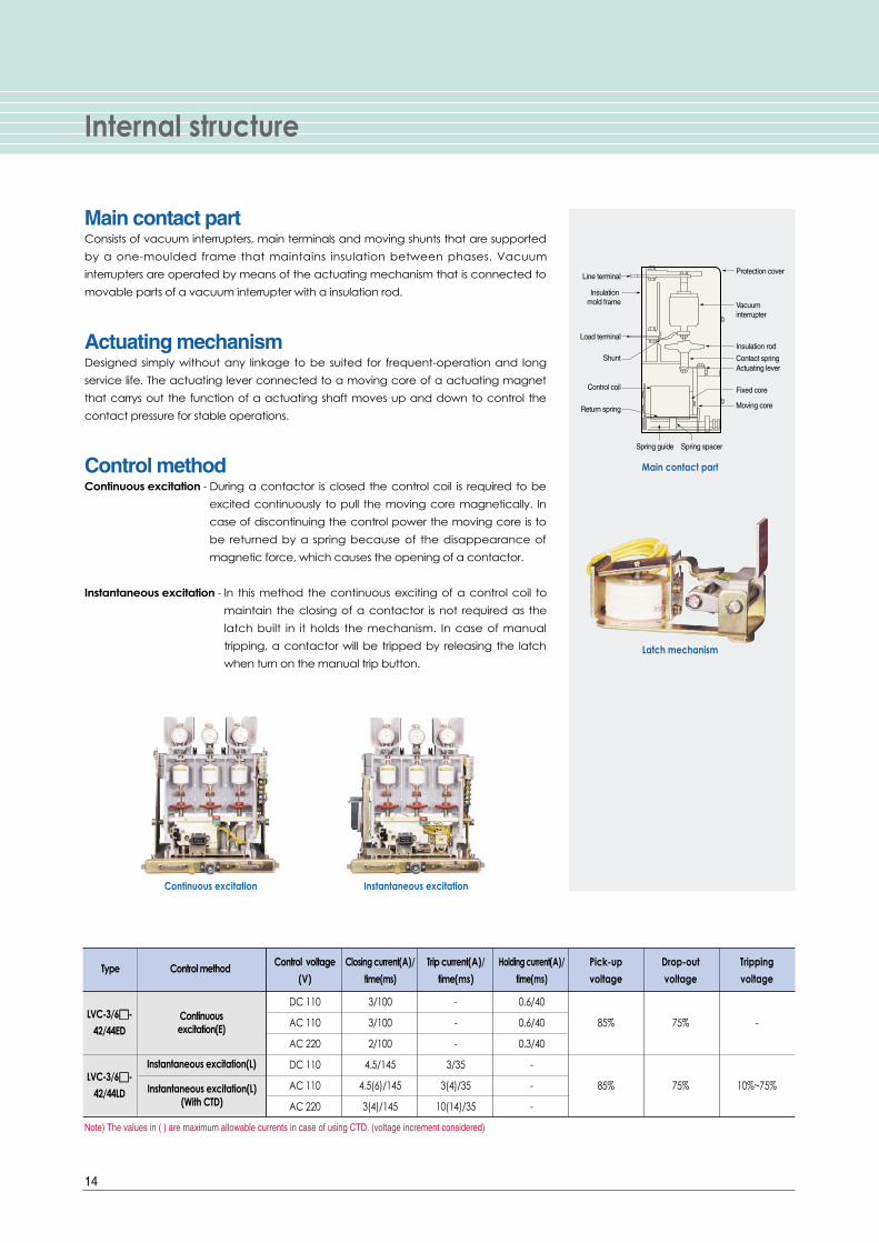
Main contact partConsists of vacuum interrupters, main terminals and moving shunts that are supported
by a one-moulded frame that maintains insulation between phases. Vacuum
interrupters are operated by means of the actuating mechanism that is connected to
movable parts of a vacuum interrupter with a insulation rod.
Actuating mechanismDesigned simply without any linkage to be suited for frequent-operation and long
service life. The actuating lever connected to a moving core of a actuating magnet
that carrys out the function of a actuating shaft moves up and down to control the
contact pressure for stable operations.
Control methodContinuous excitation - During a contactor is closed the control coil is required to be
excited continuously to pull the moving core magnetically. In
case of discontinuing the control power the moving core is to
be returned by a spring because of the disappearance of
magnetic force, which causes the opening of a contactor.
Instantaneous excitation - In this method the continuous exciting of a control coil to
maintain the closing of a contactor is not required as the
latch built in it holds the mechanism. In case of manual
tripping, a contactor will be tripped by releasing the latch
when turn on the manual trip button.
Protection coverLine terminal
Insulation mold frame
Load terminal
Shunt
Control coil
Return spring
Spring guide Spring spacer
Vacuum interrupter
Insulation rod
Contact springActuating lever
Fixed core
Moving core
Latch mechanism
Main contact part
Instantaneous excitationContinuous excitation
Type Control method Control voltage Closing current(A)/ Trip current(A)/ Holding current(A)/ Pick-up Drop-out Tripping
(V) time(ms) time(ms) time(ms) voltage voltage voltage
DC 110 3/100 - 0.6/40
AC 110 3/100 - 0.6/40 85% 75% -
AC 220 2/100 - 0.3/40
DC 110 4.5/145 3/35 -
AC 110 4.5(6)/145 3(4)/35 - 85% 75% 10%~75%
AC 220 3(4)/145 10(14)/35 -
Note) The values in ( ) are maximum allowable currents in case of using CTD. (voltage increment considered)
LVC-3/6��-42/44ED
Continuousexcitation(E)
Instantaneous excitation(L)
Instantaneous excitation(L)(With CTD)
LVC-3/6��-42/44LD

15
Vacuum interrupters
FeaturesVacuum interruptersIn the closed position, normal current flows
through the interrupter. When a fault occur
and interruption is required, the contacts are
quickly separated. The are which is oriented
between surfaces of contact shall diffuse at
the contact structure of flat shape. It prevents
local heating and damage. The arc burns in
an ionized metal vapor, which condenses on
the surrounding metal shield.
The arc is extinguished and vapor production
is ceased at current zero. The metal vapor
plasma is very rapidly dispersed, cooled,
recombined, and deionized, and the metal
vapor products are quickly condensed so that
the contacts withstand the transient recovery
voltage.
LS vacuum interrupters consists of spiral contact,
the material of which is CuCr to provide a long service life and
high withstand voltage characteristic.
Ratings
Voltage phenomena
(i) Arc re-ignition(ii)Restrikes(iii) B.I.L(iv) A.C.voltage withstand
(i) Weld(ii) Bridge explosion
(i) Contact jets(ii) Shield involvement
(i) Arc instability(ii) Interruption
Current zeroArc initiation High current arc mode
Time (ms) Time (㎲)Fault
current
Recovery voltage
Moving electrode
Moving electrode terminal
Bellows
Bellows shield
Ceramic
Arc shield
Contact
Fixed electrode terminal
Fixed electrode
Internal structureExternal view
Fixed electrode
Dimensions
AC arcing and interruption phenomena in vacuum
Rated voltage 7.2
Rated current 400
Rated interrupting current 4.5
Contact stroke 4.75
Opening speed average 0.6
Closing speed average 0.3
Contact force 7 Min
Moving side weight 0.23
Interrupter weight 0.52
Max. contact erosion 1
(kV)
(A)
(kA)
(mm)
(m/s)
(m/s)
(kg)
(kg)
(kg)
(mm)

Accessories
16
3300/6600 110/220 1 100/200 50/60
Rated voltage(V) Secondary voltage(V) Class Burden(Var) Frequency(Hz)
Fuse checker / Micro switch
PT(Potential transformer)
Fuse clip
Auxiliary switch
Fuse checker / Micro switchFuse checker is operated in case of fuse blowing and output
mechanical signal at same time. A micro switch is a part of
fuse checker. The mechanical input signal is changed to
electrical out signal by micro switch.
Note) 19-20 : NO contact, 19-21 : NC contact
PT(Potential transformer)2 each of PTs can be mounted on drawout type contactors and fuse
combination type.
These are 100VA and 200VA PTs rated 3.6/7.2kV.
Fuse clipIt is used to install or uninstall a fuse link to the holder.
Its dimensions depend on ratings.
Note) Refer to fuse selection table on page 11.
Auxiliary switchAuxiliary switches are 2NO+2NC as standard and additional 3NO+3NC can
be added on request.
Position switchThis enables checking contactor positions when draw-in and draw-out.
Remote checking is also possible through signaling via micro switches in each
position.
(Com)
(NO) (NC)

17
Drawing operations
Unlock button
Interlock plate
Unlock pin
Unlock button
Unlock plate
Cradle
Cradle
108mm(Stroke)
Interlock lever
Interlock button
A hole for a drawout lever
Cradle
Interlock lever
Interlock buttonA hole for a drawout lever
Cradle
Unlock
Unlock
Unlock pin
Details of TEST/RUN Position
<TEST Position>
<RUN Position>
<TEST Position>
<RUN Position>
For standard draw-out types (D, G)■■ When draw-in a contactor into a cradle.
1. Check that the contactor is in the state of open (TEST Position).
2. While pushing the unlock push button, insert the contactor about 50mm into the
cradle.
3. Release the unlock push button and push the contactor into the cradle by the
RUN position.
■■ When draw-out a contactor from a cradle.
1. Check that the contactor is in the state of open (RUN Position).
2. While pushing the unlock push button, draw the contactor about 50mm out of
the cradle.
3. Release the unlock push button and pull the contactor from the cradle by the
TEST position.
For direct draw-out types (DB, GB)■■ When draw-in a contactor into a cradle.
1. Check that the contactor is in the state of open (TEST Position).
2. While pushing the both sides of Interlock handle to the direction of the arrows,
insert the contactor about 50mm into the cradle.
3. Insert the drawout lever into a hole as shown in the fig. While pushing the
Interlock push button, swing the lever clockwise two times and release the
Interlock push button.
4. Turning the lever clockwise until the contactor reaches in the RUN position.
■■ When draw-out a contactor from a cradle.
1. Check that the contactor is in the state of open (RUN Position).
2. Insert the drawout lever into a hole as shown in the fig. While pushing the
Interlock push button, swing the lever counterclockwise two times and release
the Interlock push button.
4. Turning the lever counterclockwise until the contactor reaches in the TEST
position.
5. In case of separating the contactor from the cradle pull the contactor while
pushing the both sides of Interlock handle to the direction of the arrows as
shown in the fig.
Note) Check the power before connecting or disconnecting.

Electrical circuit diagram
18
Continuous excitationDC control
Fixed type (Continuous excitation)
AC control
�R : Holding resistance
�CC: Input Coil
�VZb: Assistance Switch b contact (time-delayed type)
Note1) 1,2 terminal is for power supplyNote2) 3,4 point is for Open/Close of contact pointNote3) Point line(---) is user wiring
�R: Holding resistance
�CC: Input Coil
�VZb: Assistance Switch b contact (time-delayed type)
Note1) 1,2 terminal is for power supplyNote2) 3,4 point is for Open/Close of contact pointNote3) Point line(---) is user wiring

19
Fixed type (Instantaneous excitation)Instantaneous excitationDC control
AC control(CTD equipped)
�CC: Input coil
�TC: Trip Coil
�VZb: Assistance switch b contact
�VZa: Assistance switch a contact
Note1) Close the CB by using 4(+), 2(-) terminalNote2) Trip by using 5(+), 2(-) terminalNote3) Contactor is not working when the reverse contact.Note4) Point line(---) is user wiring
�CC: Input coil
�TC: Trip Coil
�VZb: Assistance switch b contact
�VZa: Assistance switch a contact
�CTD: Condenser Trip unit
Note1) 1~2 terminal is for power supplyNote2) Close the CB by using 3~4 terminalNote3) Trip by using 5~15 terminal.Note4) Point line(---) is user wiring

Internal connection diagrams
20
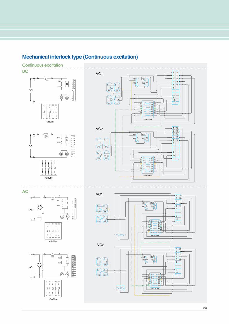
Continuous excitationDC control
(Com)
(NO) (NC)
(Com)
(NO) (NC)
Drawout type (Continuous excitation)
AC control
�R: Holding resistance
�CC: Input Coil
�VZb: Assistance Switch b contact (time-delayed type)
�M: Microswitch for interlock
Note1) 1,2 terminal is for power supplyNote2) 3,4 point is for Open/Close of contact pointNote3) Point line(---) is user wiring
�R: Holding resistance
�CC: Input Coil
�VZb: Assistance Switch b contact (time-delayed type)
�M: Microswitch for interlock
Note1) 1,2 terminal is for power supplyNote2) 3,4 point is for Open/Close of contact pointNote3) Point line(---) is user wiring

21
Drawout type (Instantaneous excitation)Instantaneous excitationDC control
(Com)
(NO) (NC)
(Com)
(NO) (NC)
AC control(CTD equipped)
�CC: Input Coil
�TC: Trip Coil
�VZb: Assistance switch b contact
�VZa: Assistance switch a contact
�M: Microswitch for interlock
Note1) Close the CB by using 4(+), 2(-) terminalNote2) Trip by using 5(+), 2(-) terminalNote3) Point line(---) is user wiringNote4) Contactor is not working when the reverse contact.
�CC: Input Coil
�TC: Trip Coil
�VZb: Assistance switch b contact
�VZa: Assistance switch a contact
�CTD: Condenser Trip unit
�M: Microswitch for interlock
Note1) 1~2 terminal is for power supplyNote2) Close the CB by using 3~4 terminalNote3) Trip by using 5~15 terminal.Note4) Point line(---) is user wiring

22
Connection diagrams
Instantaneous excitationDC
CC TC
CC TC
121314
4
5
21
10987
121314
45
12
10987
11
11
AUX S/W 1
AUX S/W 2
17
13A
B
A
B
A
A2
14
43
44
117
11
15149
13
27
x Relay
x
13A A2
14
43
44
x Relay
x
125
8
2410144
262524232221
161514131211
17117
11
15149
13
27125
8
2410144
262524232221
161514131211
VC2
VC1
<2a2b>
<2a2b>
AC
AC
AC
AC
<2a2b>
<2a2b>
CC
CC TC
TC
CTD
C6C5C3C1
12
13
14
154
5
7
1
2
3
5
1
2
3
8
9
7
9
10987 1211
1 2 3 4 5 6
10987 1211
1 2 3 4 5 6
CTD
C6C5C3C1
10
11
12
13
14
154
8
10
11
AUX S/W 1
AUX S/W 2
B
BA
A
13A A2
14
43
44
x Relay
x
13A A2
14
43
44
x Relay
x
17161514131211
11
7
11
15149
13
125
827262524232221
2410144
17161514131211
117
11
15149
13
125
827262524232221
2410144
+
~
~
-
+
~
~Z
Z
-
VC2
VC1
Mechanical interlock type (Instantaneous excitation)
AC (With CTD)
23
4
4
CCCC
10
9
12
11
6
5
2
(-)
Vzb1
R
DC
(+)
31
Vzb2
1614
1513
Vzb1
Vzb2
1513
14 1612
119
106
1 3
(+)
DC
(-)
2
5
R
CCCC
1312
23
1
1110
9
45
6
1415
16
1312
23
1
1110
9
45
6
1415
16
<3a2b>
<3a2b>
ONOFF
ONOFF
R
AC
Vzb1
CC CC
1
AC
Vzb2
3 4ONOFF
106 12 14
Vzb2R
Vzb1OFFON
CCCC
5 119 13
1
2
2
43
16
15
5
6
9 11
1210
13
14
15
16
1312
23
1
1110
9
45
6
1415
16
1312
23
1
1110
9
45
6
1415
16
<3a2b>
<3a2b>
CC
CC CC
CC CC
CC
CC CC
12
13
14
154
5
6
1
2
3
10
9
5
6
1
2
3
9
11
16
12
13
14
154
10
11
16
AUX S/W 1
AUX S/W 2
B
A
B
A
B
A
B
A
B
A
B
A
B
A
B
A
17
R11 R21
R22R R2R12
R11 R21
R22R R2R12
161514131211
115
11
15149
13
126
1624
1410
27
26
2524232221
17161514131211
11
11
15149
13
12
5 6
1624
1410
27
26
2524232221
VC2
VC1
CC CC
CC CC
121314154
123
56
109
123
56
9
11
16
121314154
1011
16
AUX S/W
AUX S/W
B
A
B
A
B
A
B
A
CC CC
CC CC
B
A
B
A
B
A
B
A
R2
R22R12
R1
R R
R2
R22R12
R1
R R
17161514131211
1115149
1311
125 6
16241014
27262524232221
17161514131211
1115149
1311
125 6
16241014
27262524232221
+~
~Z -
+~
~Z -
VC2
VC1
Mechanical interlock type (Continuous excitation)Continuous excitationDC
AC

External dimensions
24
〔〔Unit : mm〕〕
Mounting hole
(Terminal hole)
Mounting hole
(Terminal hole)
Drawout type w/o a cradleLVC-3/6D-42/44E(L)D
Combination drawout type w/o a cradle (Fused combination) LVC-3/6G-42/44E(L)D
Fixed type
LVC-3/6Z-42/44E(L)D

25
Mounting hole(Terminal hole)
(Terminal hole)
Mounting hole
(Terminal hole)(Terminal hole)
Mounting hole(Terminal hole)
(Terminal hole)
F2-Class Cradle
G-Class Cradle
〔〔Unit : mm〕〕Drawout type
E-Class Cradle
External dimensions
26
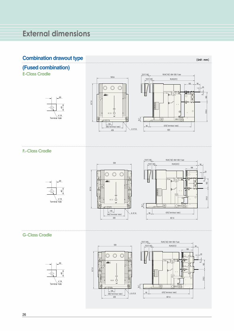
Combination drawout type
(Fused combination)
F2-Class Cradle
G-Class Cradle
4-∅14
670(Terminal hole)
617.4
340(Terminal hole)
439
105
76.7
95
503.6
820
319.3
90
RUN(672)
165
160
6
20
RUN(742):6M-300 Fuse
TEST(108)
TEST(108)E-Class Cradle
4-∅14 670(Terminal hole)
617.4
439
340(Terminal hole)
10595
76.7
559
821.6
319.3
90RUN(672)
188
20
6
160
TEST(108)
TEST(108) RUN(742):6M-300 Fuse
〔〔Unit : mm〕〕
4-∅14 670(Terminal hole)
617.4
105
439
340(Terminal hole)95
76.7
559
821.6
319.3
90
188
160
6
20
RUN(672)TEST(108)
TEST(108) RUN(742):6M-300 Fuse

27
G-Class Cradle
Direct-drawout type
(For MCSG)
Mechanical Interlock type
RUN(672)TEST(108)
TEST(108) RUN(742):6M-300 Fuse
188
4- 14
90
559
617.4
340(Terminal hole)
43976.7
95 670(Terminal hole)
821.6
299.3
200
20
6
∅
ON
〔〔Unit : mm〕〕

Selection tables
28
Ratedvoltage
(kV)
Fuse link
Ratedcurrent
(A)
Ratedinterrupting
current
(kA)
Lowestinterrupting
current
(A)
Transformer load(kVA)
Single phase Three phase
Fuse selection by load
Capacitive load(kVA)
Three phase
LFL - 3/6G -
LFL - 3/6G -
LFL - 3/6G -
LFL - 3/6G -
LFL - 3/6G -
LFL - 3/6G -
LFL - 3/6G -
LFL - 3/6G -
LFL - 3/6G -
LFL - 3/6G -
LFL - 3G -
LFL - 3G -
LFL - 6G -
LFL - 6G -
5B
10B
20B
30B
40B
50B
60B
75B
100B
125B
160B
200B
160B
200B
3.6
(7.2)
3.6
7.2
40 4In
5
10
20
30
40
50
63
75
100
125
160
200
160
200
( 8 ~ 16 )
( 13 ~ 25 )
( 30 ~ 62 )
( 40 ~ 84 )
( 80 ~ 165)
( 98 ~ 204)
(132 ~ 275)
(134 ~ 330)
(256 ~ 440)
(302 ~ 550)
( - )
( - )
(425 ~ 704)
(437 ~ 880)
※4 ~ 8
6 ~ 13
15 ~ 31
21 ~ 42
40 ~ 82
49 ~ 102
66 ~ 137
68 ~ 165
128 ~ 220
151 ~ 275
211 ~ 352
265 ~ 440
-
-
( 13 ~ 28 )
( 21 ~ 44 )
( 51 ~ 107 )
( 70 ~ 145 )
(137 ~ 286)
(170 ~ 354 )
(229 ~ 476 )
(233 ~ 571 )
(443 ~ 762 )
(522 ~ 952 )
( - )
( - )
(735~1,220 )
(755~1,520 )
※
※
6.7 ~ 14
11 ~ 22
25 ~ 53
35 ~ 73
69 ~ 143
85 ~ 117
114 ~ 238
117 ~ 285
222 ~ 381
261 ~ 476
365 ~ 610
495 ~ 762
-
-
( 9.8up to )
( 19 ~ 24 )
( 24 ~ 61 )
( 61 ~ 92 )
( 92 ~ 128)
(128 ~ 163 )
(163 ~ 210 )
(210 ~ 300 )
(300 ~ 445 )
(445 ~ 550 )
( - )
( - )
(550~742 )
(742~1,000 )
※9.8up to
9.8 ~ 12
12 ~ 31
31 ~ 46
46 ~ 64
64 ~ 81
181 ~ 105
105 ~ 150
150 ~ 222
222 ~ 275
275 ~ 370
370 ~ 550
-
-
Ratedvoltage
(kV)
Fuse link
Ratedcurrent
(A)
Ratedinterrupting
current
(kA)
Lowestinterrupting
current
(A)
Transformer load(kVA)
Single phase Three phase
Fuse selection by load
Capacitive load(kVA)
Three phase
5
10
20
30
40
50
63
75
100
150
200
300
400
150
200
300
400
20
50
100
150
200
300
400
20
50
100
150
200
300
400
-
-
-
-
-
-
-
-
-
-
-
-
-
-
- ( 5up to )
10up to ( 15up to )
20up to ( 50up to )
30up to ( 75up to )
50up to ( 100up to )
75up to ( 150up to )
- ( - )
150up to ( 200up to )
200up to ( 400up to )
300up to ( - )
400up to ( - )
625up to ( - )
750up to ( - )
- ( 500up to )
- ( 750up to )
- (1,250up to)
- ( - )
※ 5up to ( 15up to )
15up to ( 30up to )
30up to ( 75up to )
75up to ( 150up to )
100up to ( 200up to )
150up to ( 300up to )
- ( - )
200up to ( 400up to )
375up to ( 750up to )
500up to ( - )
750up to ( - )
1,000up to ( - )
1,500up to ( - )
- (1,000up to)
- (1,500up to)
- (2,000up to)
- (2,500up to)
※ - ( - )
10up to ( 25up to )
30up to ( 50up to )
50up to ( 100up to )
75up to ( 150up to )
100up to ( 200up to )
- ( - )
200up to ( 400up to )
300up to ( 600up to )
400up to ( - )
600up to ( - )
1,000up to ( - )
- ( - )
- ( 800up to )
- (1,200up to)
- ( - )
- ( - )
※
50up to ( - )
150up to ( - )
300up to ( - )
400up to ( - )
800up to ( - )
1,000up to ( - )
- ( - )
- ( 100up to )
- ( 300up to )
- ( 600up to )
- ( 800up to )
- ( - )
- ( - )
- ( - )
※
40 5In
3.6(7.2)
3.6
7.2
G(General use)type
M(Motor protection) type
3.6
7.2
40 7In
Application
Model
Application
Model
DIN type
KS type
LFL - 3/6G - 5
LFL - 3/6G - 10
LFL - 3/6G - 20
LFL - 3/6G - 30
LFL - 3/6G - 40
LFL - 3/6G - 50
LFL - 3/6G - 60
LFL - 3/6G - 75
LFL - 3/6G - 100
LFL - 3G - 150
LFL - 3G - 200
LFL - 3G - 300
LFL - 3G - 400
LFL - 6G - 150
LFL - 6G - 200
LFL - 6G - 300
LFL - 6G - 400
LFL - 3M - 20
LFL - 3M - 50
LFL - 3M - 100
LFL - 3M - 150
LFL - 3M - 200
LFL - 3M - 300
LFL - 3M - 400
LFL - 6M - 20
LFL - 6M - 50
LFL - 6M - 100
LFL - 6M - 150
LFL - 6M - 200
LFL - 6M - 300
LFL - 6M - 400
29
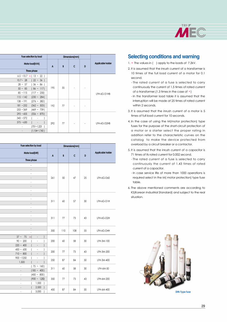
Selecting conditions and warning1. ※ The values in ( ) apply to the loads of 7.2kV.
2. It is assumed that the inrush current of a transformer is
10 times of the full load current of a motor for 0.1
second.
- The rated current of a fuse is selected to carry
continuously the current of 1.5 times of rated current
of a transformer.(1.3 times in the case of ※)
- In the transformer load table it is assumed that the
interruption will be made at 25 times of rated current
within 2 seconds.
3. It is assumed that the inrush current of a motor is 5
times of full load current for 10 seconds.
4. In the case of using the M(motor protection) type
fuses for the purpose of the short-circuit protection of
a motor or a starter select the proper rating in
addition refer to the characteristic curves on the
catalog to make the device protected from
overload by a circuit breaker or a contactor.
5. It is assumed that the inrush current of a capacitor is
71 times of its rated current for 0.002 second.
- The rated current of a fuse is selected to carry
continuously the current of 1.43 times of rated
current of a capacitor.
- In case service life of more than 1000 operations is
required select in the M( motor protection) type fuse
table.
6. The above mentioned comments are according to
KS(Korean Industrial Standard) and subject to the real
situation.
Motor load(kVA)
Three phase
Dimensions(mm)
Applicable holderA B C D
195 55 - -
LFH-6G-D1HB
192 77 - -
292 77 - - LFH-6G-D2HB
Fuse selection by load
( 13 ~ 22 )
( 22 ~ 36 )
( 36 ~ 86 )
( 86 ~ 117 )
(117 ~ 230)
(230 ~ 284 )
(276 ~ 382 )
(362 ~ 503 )
(469 ~ 739 )
(556 ~ 870 )
( - )
( - )
(751~1,223 )
(1,154~1,760 )
※6.5 ~10.7
10.7 ~ 28
28 ~ 57
50 ~ 85
85 ~ 115
115 ~ 142
138 ~ 191
181 ~ 252
253 ~ 369
293 ~ 435
343 ~ 572
375 ~ 630
-
-
Motor load(kW)
Three phase
-
-
-
-
-
-
-
-
-
-
-
-
-
-
-
-
-
Fuse selection by load
DIN-Type fuse
Dimensions(mm)
Applicable holderA B C D
261 50 47 25 LFH-6G-D60
311 60 57 30 LFH-6G-D1H
311 77 73 43 LFH-6G-D2H
350 110 108 55 LFH-6G-D4H
200 60 58 30 LFH-3M-100
200 77 73 43 LFH-3M-200
250 87 84 50 LFH-3M-400
311 60 58 30 LFH-6M-50
350 77 73 43 LFH-6M-200
450 87 84 50 LFH-6M-400
( - )
( - )
( - )
( - )
( - )
( - )
( - )
( 75 ~ 160 )
(185 ~ 400 )
(450 ~ 800 )
(900 ~ 1,250)
( 1,500 )
( 2,500 )
( 3,000 )
※37 ~ 75
90 ~ 200
220 ~ 400
450 ~ 630
710 ~ 800
900 ~1250
1,500
-
-
-
-
-
-
-
Power fuse
30
Power fuseLS Prime-MEC power fuses are designed to protect equipments from fault current such as
short-circuit, and generally used for the protection the circuits of transformers, capacitors
and motors they protect.
For further safety and reliability the elements inside of fuses are made of silver, and high
quality quartzs and and ceramic are used for magnetic rods and tubes, respectively.
LS medium voltage vacuum contactors using LS vacuum interrupters manufactured with
worldclass technology are type tested in LS PT & T that is accredited high power test lab by
worldclass KOLAS. To ensure the performance they, installed in a vacuum contactor, are
tested according to IEC 60282-1 in LS PT & T that is accredited high power test lab by
worldclass KOLAS.
Considerations in application�Power fuses are suitable for the protection from a short-circuit, Overload current will not
protected.
�Reset or re-use after blowing is not possible. Fuse reset or re-use is not possible after fused
are blown out.
�When the fuses are selected, the inrush currents arising from the starting transformers,
motors, capacitors should be considered.
�When the fuses are selected, their usage and circuit requirements should be considered.
�For the purpose of protection from the fault current below the lowest interrupting current
of the fuse it is desirable to replace it with a fuse having lower interrupting rate or add
other overcurrent relay in series
�Withstand voltage of the circuit should be higher than that of a fuse that protects it.
�If possible, select the fuse whose rated current is much higher than the load current. The
rated current not sufficiently exceeding the normal current of the load may cause
reduction in the service life.
�Replace all three fuses in case of blowing in a fuse.
Determination of the rated currentThe rated current of the fuse must be selected properly after examination of the
current/time characteristics of fuses, equipments and the related circuit conditions.
General considerations�When the fuses are selected the sufficient rated current should be considered to avoid
the deterioration of the fuse element due to sustained load current in the long term.
�The fuse rated current should be higher than the sum of all load currents.
�The estimated overload current should be within the fuse's time/current characteristics.The
estimated overload current should not exceed the allowable overload withstand currents
of the equipment and the number of its events should not exceed 100 times.
�The characteristic curve of a fuse must lie to the right of those of other equipments to be
protected.
�The withstand strength such as permissible let-through current, I²t of the equipments to be
protected must be higher than that of a fuse.
�Coordination of permissible time limit
Protection equipments in the line side < Fuses < Protection equipments in the load side
�Coordination when fuses are used as back-up protection
Permissible let-through current of a fuse < That of a protection equipment
�Use the same rating for all three phases even the differential current between phases
exists.
KERI(24kV)

31
Power fuse selection guides
Considerations by the type of load1. Power fuses for transformer loads
�The fuse with sufficient rated current must be selected to avoid the deterioration of the
fuse element due to permissible overload in the long term.
�The fuse's current/time characteristic should cover the inrush current/time of the
transformer.
�In case of power transformers the symmetrical inrush current must be within 10 times of the
fuse rating and the fuse should withstand at least 0.1second under the condition.
�Fuse rated current ≥ Transformer rated current
�The lowest interrupting current of the fuse < Short circuit current in the primary of the fuse
�In case of protection of two or more transformers
- Fuse rating should be selected on the basis of the phase condition where maximum
current flows.
- In the event of short-circuit in the secondary of the transformer
The lowest interrupting current of the fuse < Short circuit current in the primary of the
transformer
�In case of potential transformers
- When the fuses are selected do not consider the short-circuit happening in the
secondary of the PT, but protecting PT itself and the circuit against the fault in the primary
side.
- Select the fuse with higher rated current than the load current so as not to be damaged
by overcurrent.
- The characteristic curve of a fuse must lie to the right of those of other equipments to be
protected.
- The withstand strength such as permissible let-through current, I²t of the equipments to
be protected must be higher than that of a fuse.Note) Refer to the general considerations other than the above mentioned.
2. Power fuses for motor loads
�The fuse with sufficient rated current must be selected to avoid the deterioration of the
- fuse element due to permissible overload in the long term.
�The fuse's current/time characteristic should cover the inrush current/time of the motor.
- The inrush current of the motor must be within 5 times of the fuse rating and the fuse
should withstand at least 10 seconds under the condition.
Fuse rated current ≥ Motor full load currentNote) Refer to the general considerations other than the above mentioned.
3. Power fuses for combination with vacuum contactors
�The current at the intersection between a fuse characteristic curve and a contactor
operation curve should greater than the lowest interrupting current of a fuse.
�And the current at the cross point between a fuse curve and a contactor minimum
dropout curve should not greater than the rated interrupting current of a contactor.Note) Refer to the general considerations other than the above mentioned.
4. Power fuses for capacitor loads
�The fuse with sufficient rated current must be selected to avoid the deterioration of the
fuse element due to permissible overload in the long term.
�The fuse's current/time characteristic should cover the inrush current/time of the
capacitor.
�The size of inrush current depends on whether or not the serial reactors and parallel
capacitors exist.
�The inrush current of the capacitor must be within 70 times of the fuse rating and the fuse
should withstand at least 0.002 second under the condition.
Fuse rated current ≥ Capacitor rated current
�In the case of serial reactor(6%) connected the inrush current must be within 5 times of the
fuse rating and the fuse should withstand at least 0.1 second under the conditionNote) Refer to the general considerations other than the above mentioned.
Power fuses for transformer loads
Power fuses for motor loads
Note) Above picture shows koreanstandard type, If you want to orderDIN type fuse, please contact LSIndustrial Systems before youorder it.

Coordination graph
32
A. Permissible overload current/time of a transformerB. Permissible overload characteristic of a transformer, Operation characteristic curve of a FuseC. inrush current and time at no load of a transformer
Characteristic curve of a secondary circuit breaker or low voltage fuse (Converted into the primary values)
Time
Permissible overload characteristic curve of a transformerTime/Current characteristic curve of a Fuse
Blow-out characteristic curve of a Fuse
Operation characteristic curve of a Fuse
[1]
[2]
[3]
[4]
[5]
[6]
Current
Coordination between fuse and transformer circuit
When any protection device is not installed in the secondaryof a transformer�Permissible overload current of a transformer (point ③)) must lie to the left of the
curve ⓒ(time/current characteristic curve of a Fuse)Full load current of a transformer ①≤ Rated current of a fuse ④
�Point C(inrush current and time at no load of a transformer) must lie to the left ofthe point ⓒ(time/current characteristic curve of a Fuse)
�Secondary short-circuit current⑧ > Lowest interrupting current of a fuse ⑥Point B must lie to the left of the secondary short-circuit current⑧.
�Primary short-circuit current⑩ < Rated interrupting current of a fuse⑪
When a circuit breaker or fuse is installed in the secondary ofa transformer�Must meet the requirements above mentioned in ①�The characteristic curve of a secondary circuit breaker or low voltage fuse ⓐ
must lie to the left of permissible overload characteristic curve of a transformer ⓑand under the point B
�The characteristic curve of a secondary circuit breaker or low voltage fuse ⓐmust lie to the Time/Current characteristic curve of a Fuse and under theSecondary short-circuit current ⑧.
�Secondary short-circuit current⑧ < Characteristic curve of a secondary circuitbreaker or low voltage fuse ⓐ
�The secondary circuit breaker or low voltage fuse should meet the abovementioned requirements to each branch circuit.
�Another medium voltage protection device is required for the ensured protectionagainst the fault happening between the secondary protection devices and theinternal short-circuit of a transformer in the zone of [3]+[4]+[5].
※※ Coordination in the graph��Zone of [1] : Protection of primary side from short-
circuit by a fuse��Zone of [2] : Protection of a transformer��Zone of [3] : Out of the scope of fuse operation��Zone of [4] : Interruption is not ensured even
though the fuse blows.��Zone of [5] : Protection of a transformer is not
ensured even though the fuseinterrupts the circuit.
��Zone of [3]+[4]+[5] : No protection zone of atransformer Circuit breaker orlow voltage fuse required forthe transformer protection
Fuse
Transformer
Circuit breakeror low voltage fuse
Full load current of a transformer The lowest interrupting current of the secondary circuit breakerPermissible overload current of a transformerRated current of a fuseLowest blow-out current of a fuseLowest interrupting current of a fuseInrush current at no load of a transformerSecondary short-circuit currentRated interrupting current of a secondary circuit breakerPrimary short-circuit currentRated interrupting current of a fuse
33
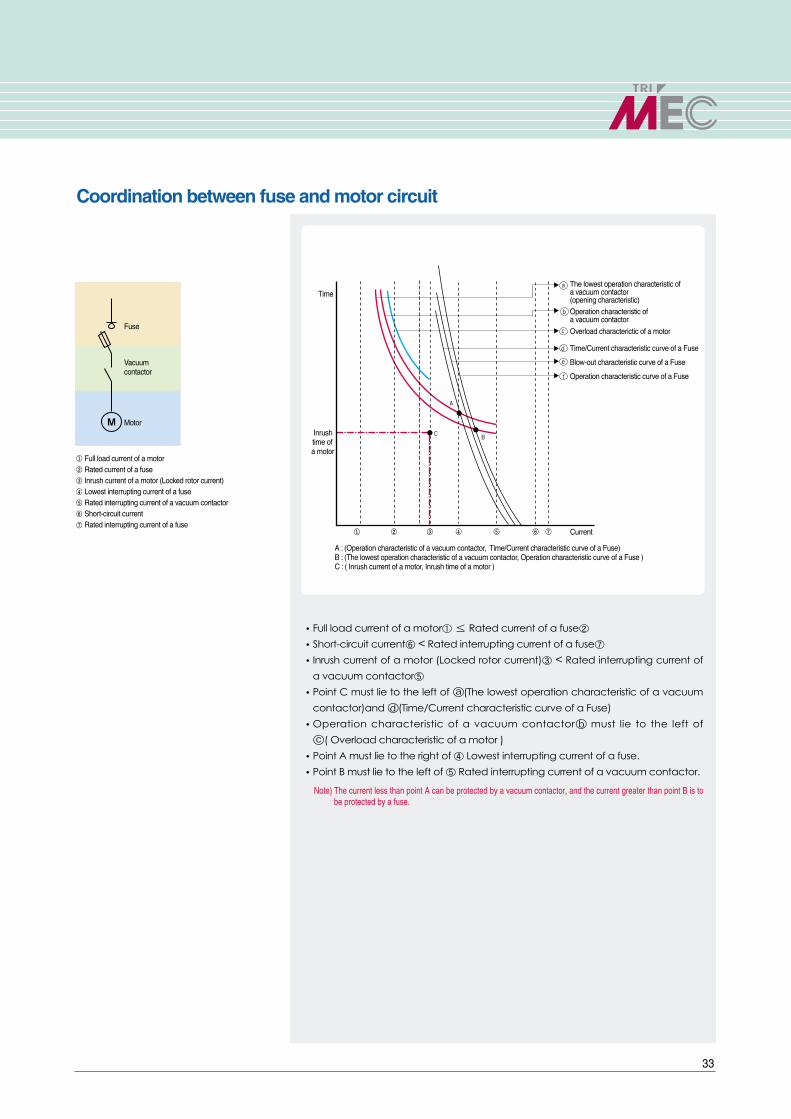
Coordination between fuse and motor circuit
The lowest operation characteristic of a vacuum contactor(opening characteristic)
Operation characteristic ofa vacuum contactor
Overload characterictic of a motor
Time/Current characteristic curve of a Fuse
Blow-out characteristic curve of a Fuse
Operation characteristic curve of a Fuse
A : (Operation characteristic of a vacuum contactor, Time/Current characteristic curve of a Fuse)B : (The lowest operation characteristic of a vacuum contactor, Operation characteristic curve of a Fuse )C : ( Inrush current of a motor, Inrush time of a motor )
Inrush time of a motor
Time
Current
�Full load current of a motor①≤ Rated current of a fuse②
�Short-circuit current⑥ < Rated interrupting current of a fuse⑦
�Inrush current of a motor (Locked rotor current)③ < Rated interrupting current of
a vacuum contactor⑤
�Point C must lie to the left of ⓐ(The lowest operation characteristic of a vacuum
contactor)and ⓓ(Time/Current characteristic curve of a Fuse)
�Operation characteristic of a vacuum contactorⓑ must lie to the left of
ⓒ( Overload characteristic of a motor )
�Point A must lie to the right of ④ Lowest interrupting current of a fuse.
�Point B must lie to the left of ⑤ Rated interrupting current of a vacuum contactor.
Note) The current less than point A can be protected by a vacuum contactor, and the current greater than point B is tobe protected by a fuse.
Fuse
Vacuum contactor
Motor
Full load current of a motorRated current of a fuseInrush current of a motor (Locked rotor current)Lowest interrupting current of a fuseRated interrupting current of a vacuum contactorShort-circuit current Rated interrupting current of a fuse

Operation curves
34
DIN Type3.6/7.2kV blowing characteristic 3.6/7.2kV current limiting characteristic
3.6kV blowing characteristic 3.6kV current limiting characteristic
7.2kV blowing characteristic 7.2kV current limiting characteristic
Current ( sym, A )
Ope
ratio
n tim
e(se
c)
Current ( sym, A )
Ope
ratio
n tim
e(se
c)
Current ( sym, A )
Ope
ratio
n tim
e(se
c)
Interrupting current ( sym, kA )
Interrupting current ( sym, kA )
Cur
rent
lim
ited
( pe
ak, k
A )
C
urre
nt li
mite
d (
peak
, kA
)
Interrupting current ( sym, kA )
Cur
rent
lim
ited
( pe
ak, k
A )

35
KS TypeG(General use) type fuse
M(Motor protection) type fuse
3.6/7.2kV blowing characteristic 3.6/7.2kV current limiting characteristic
3.6kV blowing characteristic 7.2kV blowing characteristic
3.6kV, 7.2kV current limiting characteristic
Current ( sym, A )
Ope
ratio
n tim
e(se
c)
Current ( sym, A )
Ope
ratio
n tim
e(se
c)
Interrupting current ( sym, kA )
Interrupting current ( sym, kA )
Cur
rent
lim
ited
( pe
ak, k
A )
Cur
rent
lim
ited
( pe
ak, k
A )
Current ( sym, A )
Ope
ratio
n tim
e(se
c)

��For your safety, please read user's manual thoroughly before operating.
��Contact the nearest authorized service facility for examination, repair, or adjustment.
��Please contact qualified service technician when you need maintenance.Do not disassemble or repair by yourself!
��Any maintenance and inspection shall be performed by the personnel having expertise concerned.Safety Instructions
��LS Industrial Systems (Middle East) FZE ����Dubai, U.A.E. Address: P.O.Box-114216, API World Tower, 303B, Sheikhe Zayed Road, Dubai, U.A.E. Tel: 971-4-332-8289 Fax: 971-4-332-9444 e-mail: [email protected]
��Dalian LS Industrial Systems Co., Ltd. ����Dalian, ChinaAddress: No.15, Liaohexi 3-Road, Economic and Technical Development zone, Dalian 116600, ChinaTel: 86-411-8273-7777 Fax: 86-411-8730-7560 e-mail: [email protected]
��LS Industrial Systems (Wuxi) Co., Ltd. ����Wuxi, chinaAddress: 102-A , National High & New Tech Industrial Development Area, Wuxi, Jiangsu,214028, P.R.ChinaTel: 86-510-8534-6666 Fax: 86-510-522-4078 e-mail: [email protected]
��LS-VINA Industrial Systems Co., Ltd. ����Hanoi, VietnamAddress: Nguyen Khe - Dong Anh - Ha Noi - Viet NamTel: 84-4-882-0222 Fax: 84-4-882-0220 e-mail: [email protected]
��LS Industrial Systems Tokyo Office ����Tokyo, JapanAddress: 16FL, Higashi-Kan, Akasaka Twin Tower 17-22, 2-chome, Akasaka, Minato-ku Tokyo 107-8470, JapanTel: 81-3-3582-9128 Fax: 81-3-3582-2667 e-mail: [email protected]
��LS Industrial Systems Shanghai Office ����Shanghai, ChinaAddress: Room E-G, 12th Floor Huamin Empire Plaza, No.726, West Yan'an Road Shanghai 200050, P.R. ChinaTel: 86-21-5237-9977 (609) Fax: 89-21-5237-7191 e-mail: [email protected]
��LS Industrial Systems Beijing Office ����Beijing, ChinaAddress: B-Tower 17FL.Beijing Global Trade Center B/D. No.36, BeiSanHuanDong-Lu, DongCheng-District,Beijing 100013, P.R. ChinaTel: 86-10-5825-6025,7 Fax: 86-10-5825-6026 e-mail: [email protected]
��LS Industrial Systems Guangzhou Office ����Guangzhou, ChinaAddress: Room 1403,14F,New Poly Tower,2 Zhongshan Liu Road,Guangzhou, P.R. ChinaTel: 86-20-8326-6764 Fax: 86-20-8326-6287 e-mail: [email protected]
��LS Industrial Systems Chengdu Office ����Chengdu, ChinaAddress: 12Floor, Guodong Buiding, No52 Jindun Road Chengdu, 610041, P.R. ChinaTel: 86-28-8612-9151 Fax: 86-28-8612-9236 e-mail: [email protected]
��LS Industrial Systems Qingdao Office ����Qingdao, ChinaAddress: 7B40,Haixin Guangchang Shenye Building B, No.9, Shandong Road Qingdao 26600, P.R. ChinaTel: 86-532-8501-6568 Fax: 86-532-583-3793 e-mail: [email protected]
�� HEAD OFFICELS Tower 1026-6, Hogye-dong, Dongan-gu, Anyang-si, Gyeonggi-do 431-848, KoreaTel. (82-2)2034-4870Fax. (82-2)2034-4713
�� CHEONG-JU PLANTCheong-Ju Plant #1, Song Jung Dong, Hung Duk Ku,Cheong Ju, 361-720, Korea
Leader in Electrics & Automation
��Global Network
www.lsis.biz
Specifications in this catalog are subject to change without notice due to continuous product development and improvement.
2009. 01 LS Medium Voltage Vacuum Contactors(E) 2003. 04/(15) 2009. 01 Printed in Korea STAFF
ⓒ 2003.4 LS Industrial Systems Co.,Ltd. All rights reserved.


![Catalogo baja tension SIEMENS[1]](https://img.dokumen.tips/doc/110x75/5571fc4c497959916996f0ba/catalogo-baja-tension-siemens1.jpg)