Embed Size (px)
Citation preview

CASIO fx-7400G PLUS POWER GRAPHIC
Engineering Surveyor Programs
Reference Manual
Revision 3.0: November 2009
EEENNNGGGIIINNNEEEEEERRRIIINNNGGG
SSSUUURRRVVVEEEYYYOOORRR
© Mark Adams 2009 www.engineeringsurveyor.com

Casio fx-7400G Plus Power Graphic Engineering Surveyor Programs
Page 2 of 41
CONTENTS
INTRODUCTION 3
PROGRAMS 1. 1PT~CFIX 5 2. 2PT~CFIX 6 3. 3D~CFIX 7 4. 3PT~CFIX 8 5. ANGLE 9 6. AREA 10 7. BRG~DIST 11 8. CIRCLE 12 9. COLUMN 13 10. CURVE 14 11. CUT~AREA 15 12. INT~SECT 16 13. INT~SECT2 17 14. LEVELS 18 15. MEAN~XY 19 16. NOTEBOOK 20 17. OFFSET 21 18. POLYGON 22 19. PT2PLANE 23 20. RADIAL 24 21. RESECT 25 22. SURVEY 26 23. SURVEY2D 27 24. TRANSFRM 28 25. TRAVERSE 29 26. UNI~COLS 30 27. VECTORS 31 28. VERTICAL 32
EXAMPLES 33 REVISIONS 40 COPYRIGHT NOTICE 41
Casio fx-7400G Plus Power Graphic Engineering Surveyor Programs
Page 3 of 41
INTRODUCTION
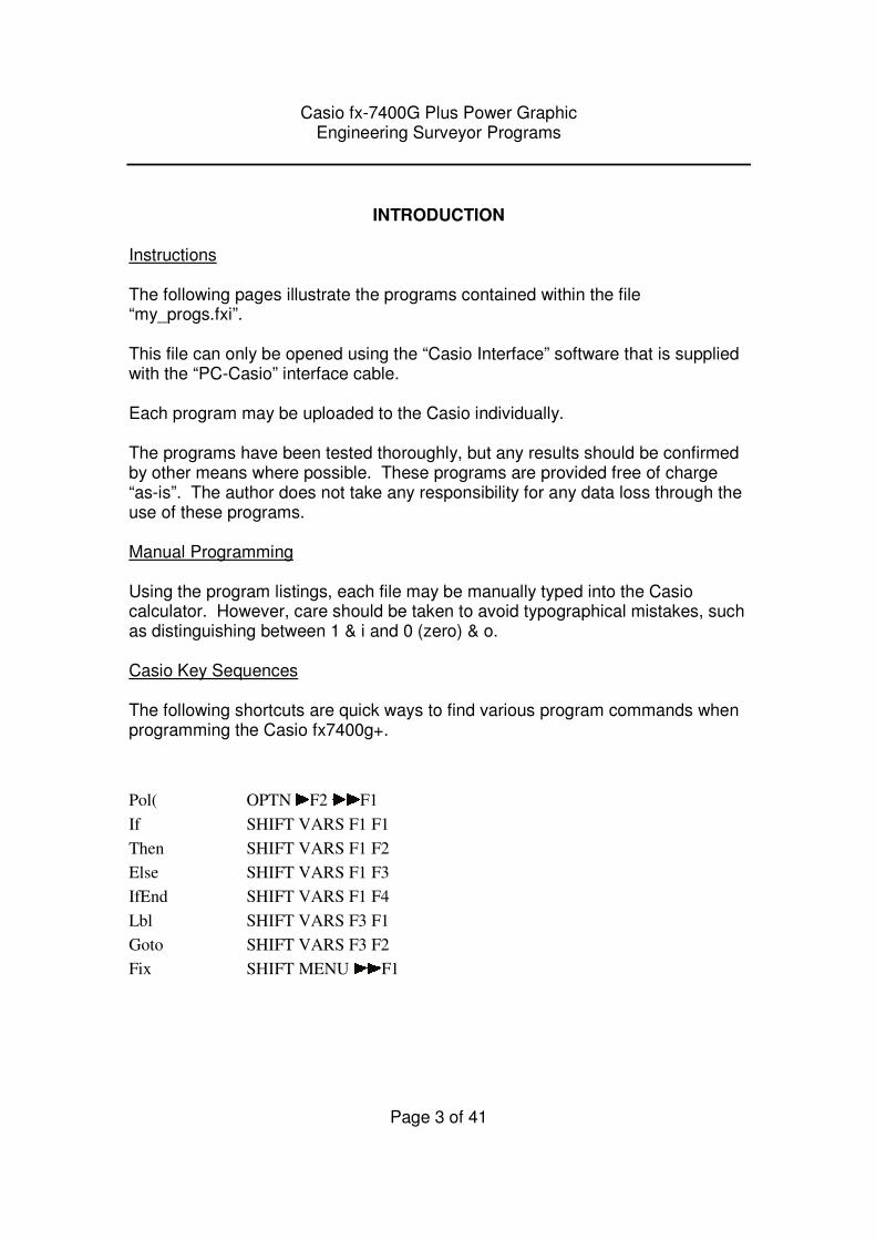
Instructions The following pages illustrate the programs contained within the file “my_progs.fxi”. This file can only be opened using the “Casio Interface” software that is supplied with the “PC-Casio” interface cable. Each program may be uploaded to the Casio individually. The programs have been tested thoroughly, but any results should be confirmed by other means where possible. These programs are provided free of charge “as-is”. The author does not take any responsibility for any data loss through the use of these programs. Manual Programming Using the program listings, each file may be manually typed into the Casio calculator. However, care should be taken to avoid typographical mistakes, such as distinguishing between 1 & i and 0 (zero) & o. Casio Key Sequences The following shortcuts are quick ways to find various program commands when programming the Casio fx7400g+.
Pol( OPTN F2 F1
If SHIFT VARS F1 F1
Then SHIFT VARS F1 F2
Else SHIFT VARS F1 F3
IfEnd SHIFT VARS F1 F4
Lbl SHIFT VARS F3 F1
Goto SHIFT VARS F3 F2
Fix SHIFT MENU F1
Casio fx-7400G Plus Power Graphic Engineering Surveyor Programs
Page 4 of 41
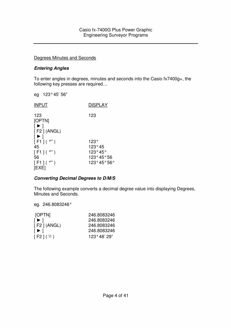
Degrees Minutes and Seconds Entering Angles To enter angles in degrees, minutes and seconds into the Casio fx7400g+, the following key presses are required… eg 123° 45’ 56” INPUT DISPLAY 123 123 [OPTN] [ ► ] [ F2 ] (ANGL) [ ► ] [ F1 ] ( °’” ) 123° 45 123° 45 [ F1 ] ( °’” ) 123° 45° 56 123° 45° 56 [ F1 ] ( °’” ) 123° 45° 56° [EXE] Converting Decimal Degrees to D/M/S The following example converts a decimal degree value into displaying Degrees, Minutes and Seconds. eg. 246.8083246° [OPTN] 246.8083246 [ ► ] 246.8083246 [ F2 ] (ANGL) 246.8083246 [ ► ] 246.8083246
[ F2 ] ( °’” ) 123° 48’ 29”
Casio fx-7400G Plus Power Graphic Engineering Surveyor Programs
Page 5 of 41
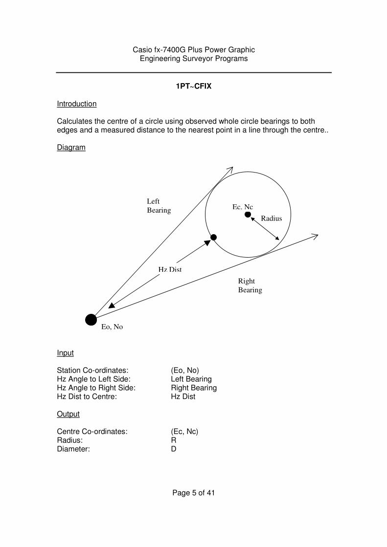
1PT~CFIX Introduction Calculates the centre of a circle using observed whole circle bearings to both edges and a measured distance to the nearest point in a line through the centre.. Diagram
Input Station Co-ordinates: (Eo, No) Hz Angle to Left Side: Left Bearing Hz Angle to Right Side: Right Bearing Hz Dist to Centre: Hz Dist Output Centre Co-ordinates: (Ec, Nc) Radius: R Diameter: D
Eo, No
Ec, Nc
Right
Bearing
Left
Bearing
Hz Dist
Radius
Casio fx-7400G Plus Power Graphic Engineering Surveyor Programs
Page 6 of 41
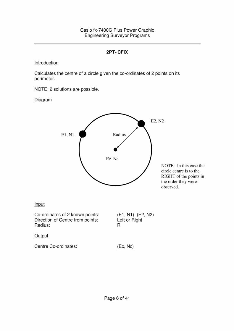
2PT~CFIX Introduction Calculates the centre of a circle given the co-ordinates of 2 points on its perimeter. NOTE: 2 solutions are possible. Diagram
Input Co-ordinates of 2 known points: (E1, N1) (E2, N2) Direction of Centre from points: Left or Right Radius: R Output Centre Co-ordinates: (Ec, Nc)
E2, N2
E1, N1
Ec, Nc
Radius
NOTE: In this case the
circle centre is to the
RIGHT of the points in
the order they were
observed.
Casio fx-7400G Plus Power Graphic Engineering Surveyor Programs
Page 7 of 41
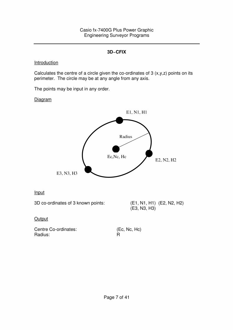
3D~CFIX Introduction Calculates the centre of a circle given the co-ordinates of 3 (x,y,z) points on its perimeter. The circle may be at any angle from any axis. The points may be input in any order. Diagram
Input 3D co-ordinates of 3 known points: (E1, N1, H1) (E2, N2, H2)
(E3, N3, H3) Output Centre Co-ordinates: (Ec, Nc, Hc) Radius: R
E2, N2, H2
E3, N3, H3
Ec,Nc, Hc
Radius
E1, N1, H1

Casio fx-7400G Plus Power Graphic Engineering Surveyor Programs
Page 8 of 41
3PT~CFIX
Introduction Calculates the centre of a circle given the co-ordinates of 3 points on its perimeter. Diagram
Input Co-ordinates of 3 known points: (E1, N1) (E2, N2) (E3, N3) Output Centre Co-ordinates: (Ec, Nc) Radius: R Diameter: D
E1, N1
E2, N2
E3, N3
Ec, Nc
Radius
Diameter
Casio fx-7400G Plus Power Graphic Engineering Surveyor Programs
Page 9 of 41
ANGLE
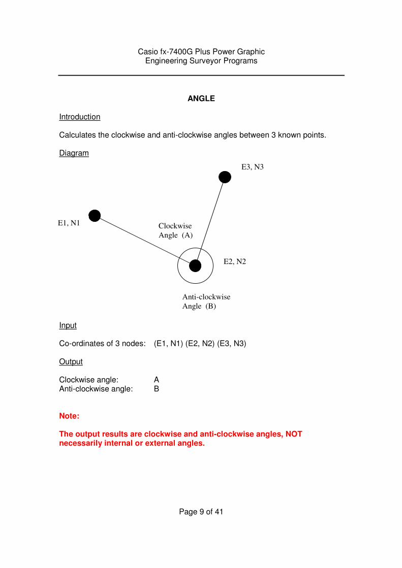
Introduction Calculates the clockwise and anti-clockwise angles between 3 known points. Diagram Input Co-ordinates of 3 nodes: (E1, N1) (E2, N2) (E3, N3) Output Clockwise angle: A Anti-clockwise angle: B Note: The output results are clockwise and anti-clockwise angles, NOT necessarily internal or external angles.
E3, N3
E1, N1
E2, N2
Clockwise
Angle (A)
Anti-clockwise
Angle (B)
Casio fx-7400G Plus Power Graphic Engineering Surveyor Programs
Page 10 of 41
AREA
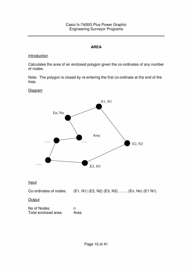
Introduction Calculates the area of an enclosed polygon given the co-ordinates of any number of nodes. Note: The polygon is closed by re-entering the first co-ordinate at the end of the loop. Diagram
Input Co-ordinates of nodes: (E1, N1) (E2, N2) (E3, N3) ……. (En, Nn) (E1 N1) Output No of Nodes: n Total enclosed area: Area
E1, N1
E2, N2
E3, N3
En, Nn
Area
…..
…..
…..
Casio fx-7400G Plus Power Graphic Engineering Surveyor Programs
Page 11 of 41
BRG~DIST
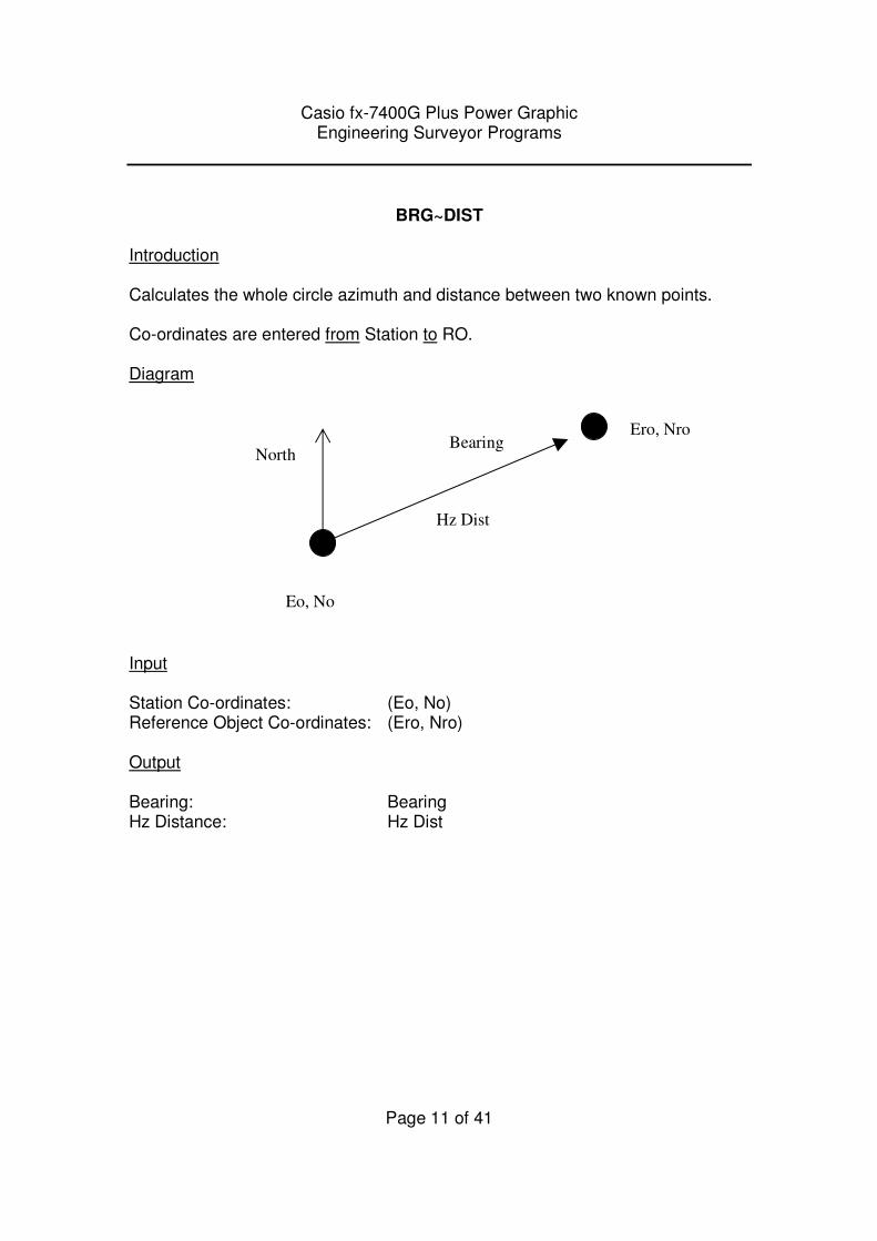
Introduction Calculates the whole circle azimuth and distance between two known points. Co-ordinates are entered from Station to RO. Diagram
Input Station Co-ordinates: (Eo, No) Reference Object Co-ordinates: (Ero, Nro) Output Bearing: Bearing Hz Distance: Hz Dist
Ero, Nro
North Bearing
Hz Dist
Eo, No
Casio fx-7400G Plus Power Graphic Engineering Surveyor Programs
Page 12 of 41
CIRCLE
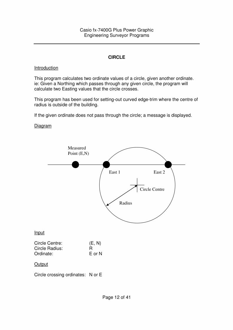
Introduction This program calculates two ordinate values of a circle, given another ordinate. ie: Given a Northing which passes through any given circle, the program will calculate two Easting values that the circle crosses. This program has been used for setting-out curved edge-trim where the centre of radius is outside of the building. If the given ordinate does not pass through the circle; a message is displayed. Diagram
Input Circle Centre: (E, N) Circle Radius: R Ordinate: E or N Output Circle crossing ordinates: N or E
Measured
Point (E,N)
East 1 East 2
Radius
Circle Centre
Casio fx-7400G Plus Power Graphic Engineering Surveyor Programs
Page 13 of 41
COLUMN
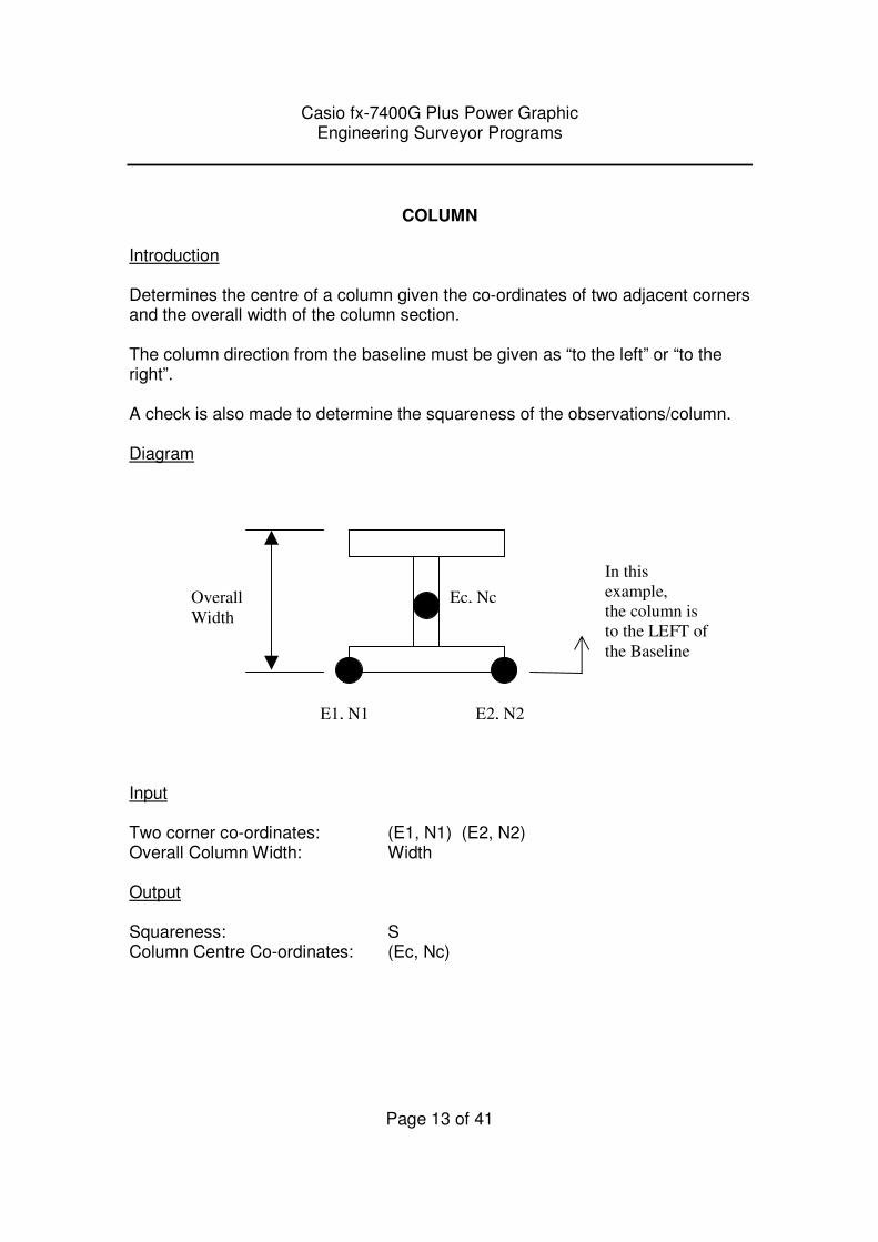
Introduction Determines the centre of a column given the co-ordinates of two adjacent corners and the overall width of the column section. The column direction from the baseline must be given as “to the left” or “to the right”. A check is also made to determine the squareness of the observations/column. Diagram
Input Two corner co-ordinates: (E1, N1) (E2, N2) Overall Column Width: Width Output Squareness: S Column Centre Co-ordinates: (Ec, Nc)
E2, N2
In this
example,
the column is
to the LEFT of
the Baseline
Ec, Nc Overall
Width
E1, N1
Casio fx-7400G Plus Power Graphic Engineering Surveyor Programs
Page 14 of 41
CURVE
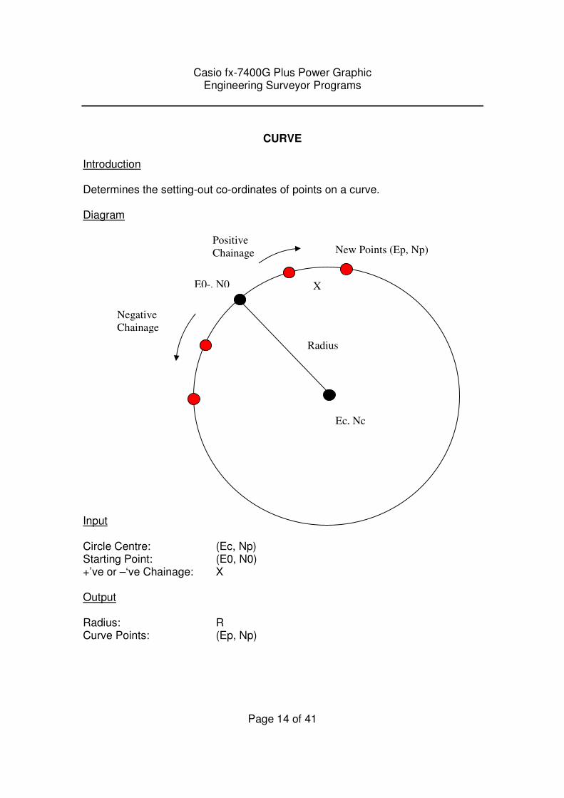
Introduction Determines the setting-out co-ordinates of points on a curve. Diagram Input Circle Centre: (Ec, Np) Starting Point: (E0, N0) +’ve or –‘ve Chainage: X Output Radius: R Curve Points: (Ep, Np)
Ec, Nc
E0-, N0
Negative
Chainage
Positive
Chainage New Points (Ep, Np)
Radius
X
Casio fx-7400G Plus Power Graphic Engineering Surveyor Programs
Page 15 of 41
CUT~AREA
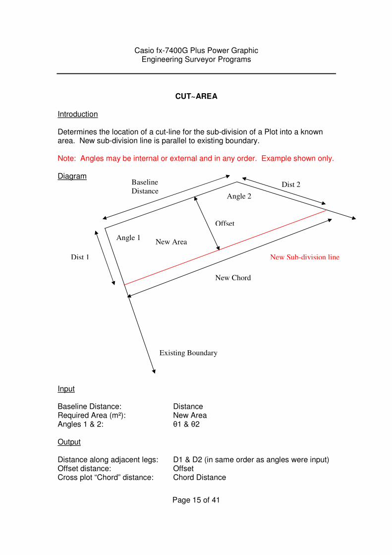
Introduction Determines the location of a cut-line for the sub-division of a Plot into a known area. New sub-division line is parallel to existing boundary. Note: Angles may be internal or external and in any order. Example shown only. Diagram Input Baseline Distance: Distance Required Area (m²): New Area Angles 1 & 2: θ1 & θ2 Output Distance along adjacent legs: D1 & D2 (in same order as angles were input) Offset distance: Offset Cross plot “Chord” distance: Chord Distance
New Sub-division line
New Area
Existing Boundary
Dist 1
Dist 2
Angle 1
Angle 2
Baseline
Distance
Offset
New Chord
Casio fx-7400G Plus Power Graphic Engineering Surveyor Programs
Page 16 of 41
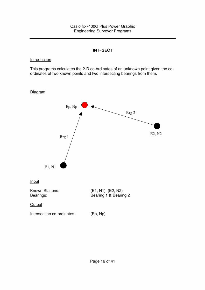
INT~SECT
Introduction This programs calculates the 2-D co-ordinates of an unknown point given the co-ordinates of two known points and two intersecting bearings from them. Diagram
Input Known Stations: (E1, N1) (E2, N2) Bearings: Bearing 1 & Bearing 2 Output Intersection co-ordinates: (Ep, Np)
E1, N1
E2, N2
Ep, Np
Brg 1
Brg 2
Casio fx-7400G Plus Power Graphic Engineering Surveyor Programs
Page 17 of 41
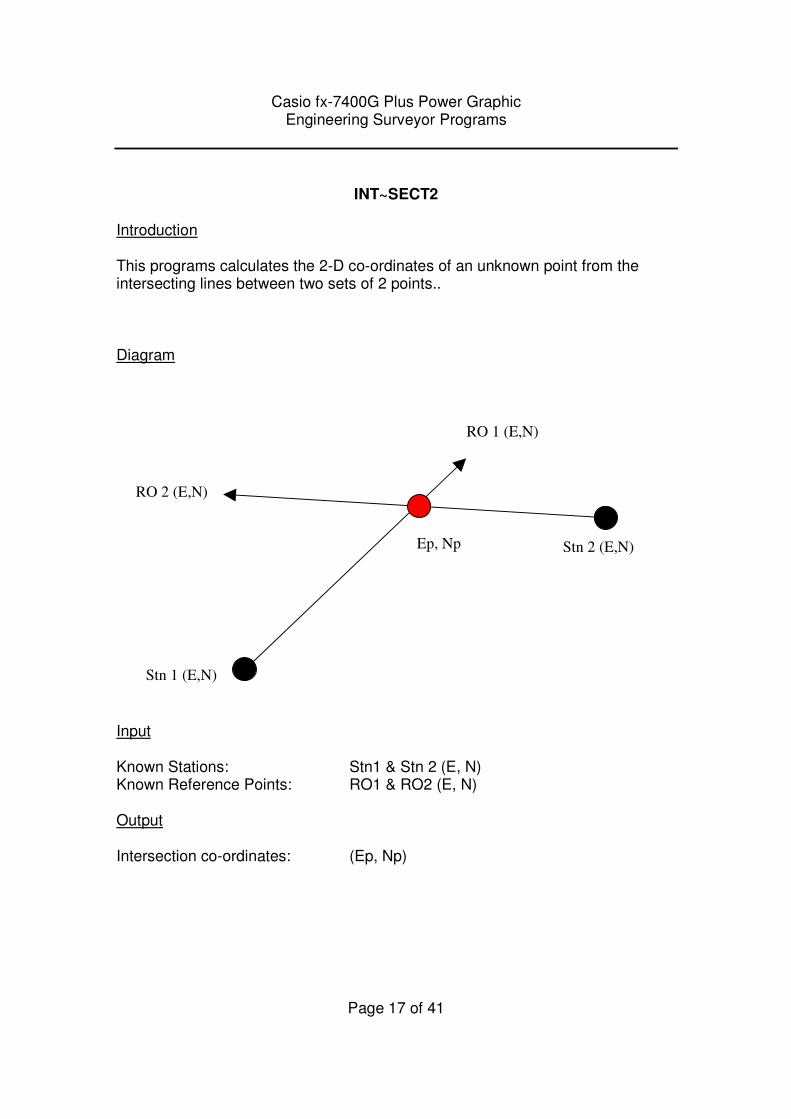
INT~SECT2
Introduction This programs calculates the 2-D co-ordinates of an unknown point from the intersecting lines between two sets of 2 points.. Diagram
Input Known Stations: Stn1 & Stn 2 (E, N) Known Reference Points: RO1 & RO2 (E, N) Output Intersection co-ordinates: (Ep, Np)
Stn 1 (E,N)
Stn 2 (E,N) Ep, Np
RO 2 (E,N)
RO 1 (E,N)
Casio fx-7400G Plus Power Graphic Engineering Surveyor Programs
Page 18 of 41
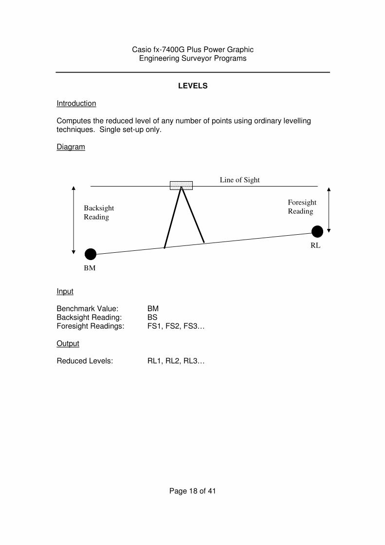
LEVELS
Introduction Computes the reduced level of any number of points using ordinary levelling techniques. Single set-up only. Diagram
Input Benchmark Value: BM Backsight Reading: BS Foresight Readings: FS1, FS2, FS3… Output Reduced Levels: RL1, RL2, RL3…
BM
Backsight
Reading
Foresight
Reading
RL
Line of Sight
Casio fx-7400G Plus Power Graphic Engineering Surveyor Programs
Page 19 of 41
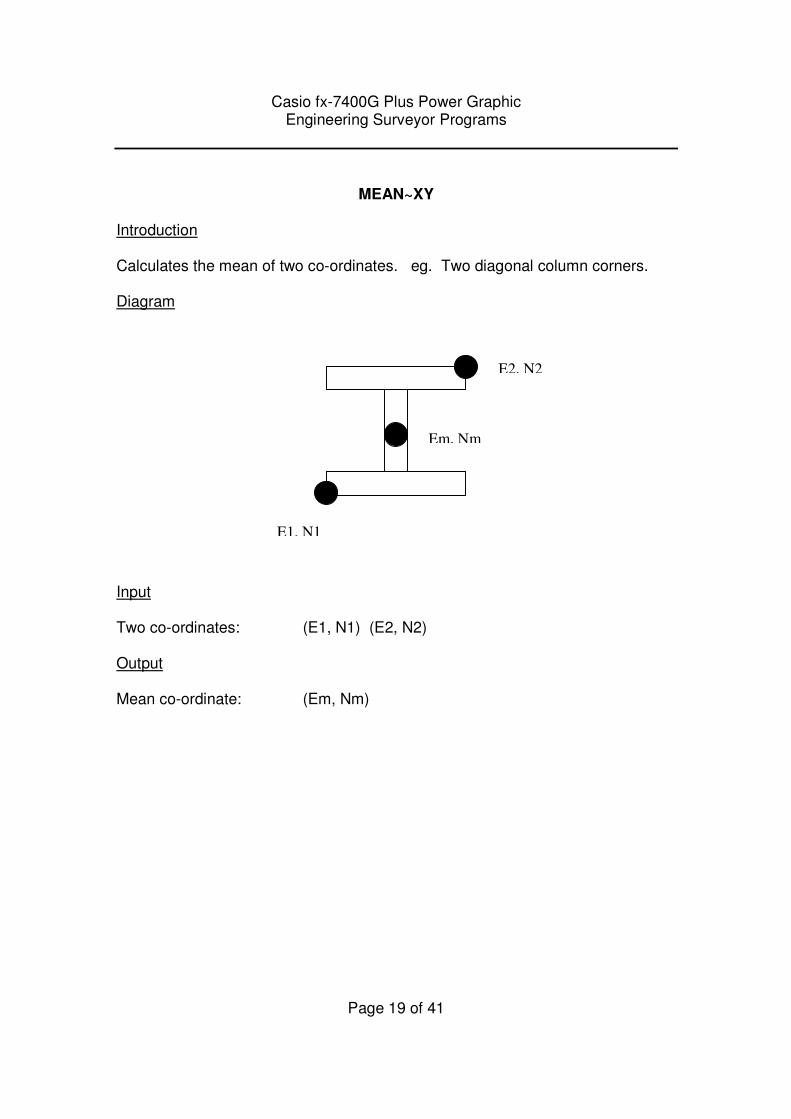
MEAN~XY
Introduction Calculates the mean of two co-ordinates. eg. Two diagonal column corners. Diagram
Input Two co-ordinates: (E1, N1) (E2, N2) Output Mean co-ordinate: (Em, Nm)
E2, N2
Em, Nm
E1, N1

Casio fx-7400G Plus Power Graphic Engineering Surveyor Programs
Page 20 of 41
NOTEBOOK
Introduction Stores up to 9 numeric values when a pen and paper aren’t available. Input Numeric values: N1, N2, N3…..N9 Output Numeric values: N1, N2, N3…..N9 Note: The values may be overwritten/changed when another program is used. This program should only be used for temporary storage only.
Casio fx-7400G Plus Power Graphic Engineering Surveyor Programs
Page 21 of 41
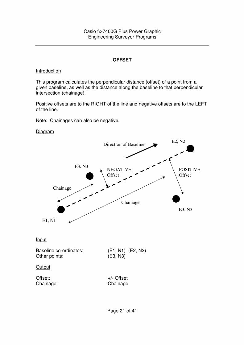
OFFSET
Introduction This program calculates the perpendicular distance (offset) of a point from a given baseline, as well as the distance along the baseline to that perpendicular intersection (chainage). Positive offsets are to the RIGHT of the line and negative offsets are to the LEFT of the line. Note: Chainages can also be negative. Diagram
Input Baseline co-ordinates: (E1, N1) (E2, N2) Other points: (E3, N3) Output Offset: +/- Offset Chainage: Chainage
E1, N1
E2, N2
E3, N3
E3, N3
NEGATIVE
Offset
Chainage
POSITIVE
Offset
Chainage
Direction of Baseline
Casio fx-7400G Plus Power Graphic Engineering Surveyor Programs
Page 22 of 41
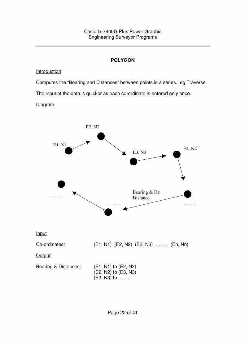
POLYGON
Introduction Computes the “Bearing and Distances” between points in a series. eg Traverse. The input of the data is quicker as each co-ordinate is entered only once. Diagram
Input Co-ordinates: (E1, N1) (E2, N2) (E3, N3) …….. (En, Nn) Output Bearing & Distances: (E1, N1) to (E2, N2) (E2, N2) to (E3, N3) (E3, N3) to …….
E1, N1
E2, N2
E3, N3 E4, N4
…….. ……..
……. Bearing & Hz
Distance
Casio fx-7400G Plus Power Graphic Engineering Surveyor Programs
Page 23 of 41
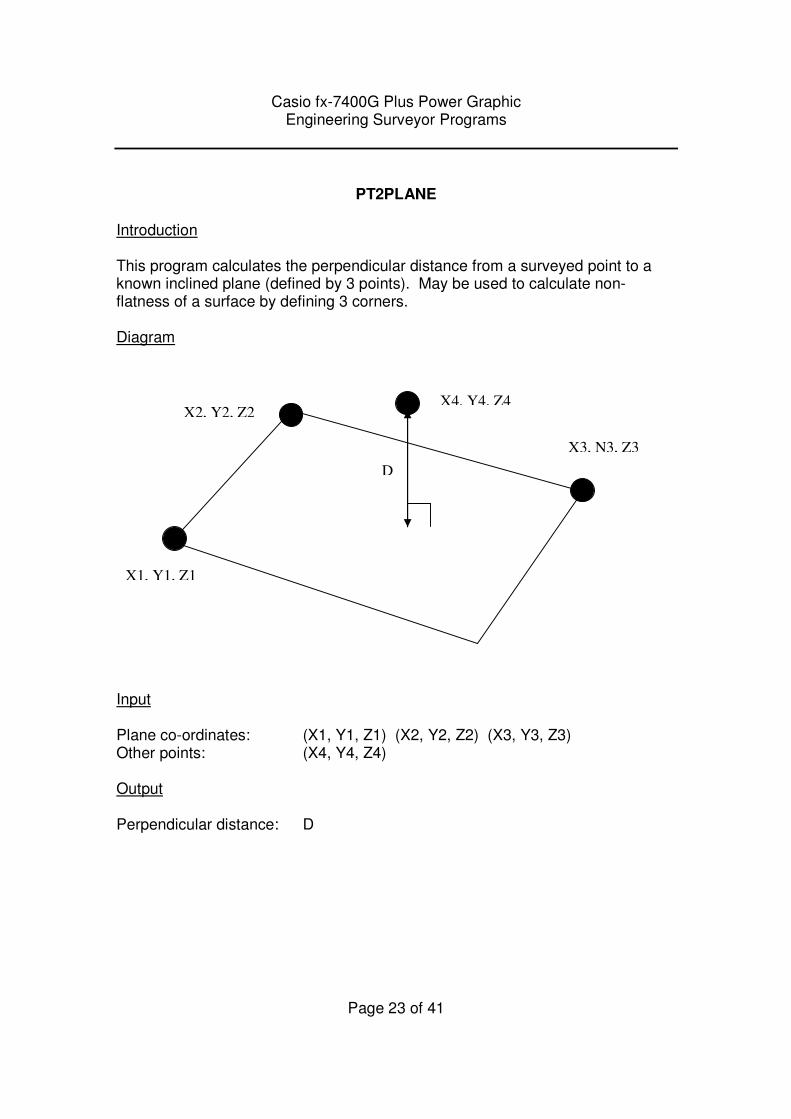
PT2PLANE
Introduction This program calculates the perpendicular distance from a surveyed point to a known inclined plane (defined by 3 points). May be used to calculate non-flatness of a surface by defining 3 corners. Diagram
Input Plane co-ordinates: (X1, Y1, Z1) (X2, Y2, Z2) (X3, Y3, Z3) Other points: (X4, Y4, Z4) Output Perpendicular distance: D
X1, Y1, Z1
X3, N3, Z3
X2, Y2, Z2 X4, Y4, Z4
D
Casio fx-7400G Plus Power Graphic Engineering Surveyor Programs
Page 24 of 41
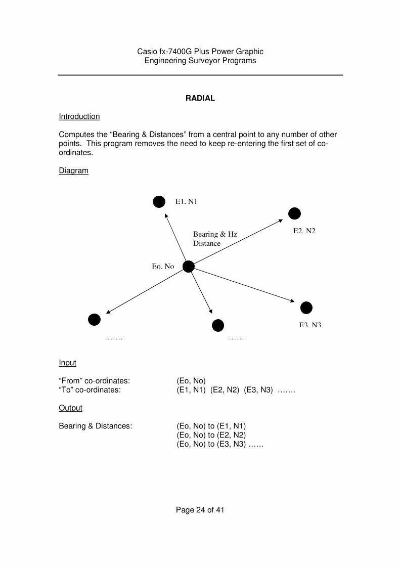
RADIAL
Introduction Computes the “Bearing & Distances” from a central point to any number of other points. This program removes the need to keep re-entering the first set of co-ordinates. Diagram
Input “From” co-ordinates: (Eo, No) “To” co-ordinates: (E1, N1) (E2, N2) (E3, N3) ……. Output Bearing & Distances: (Eo, No) to (E1, N1) (Eo, No) to (E2, N2) (Eo, No) to (E3, N3) ……
Eo, No
E1, N1
E2, N2
E3, N3
…… …….
Bearing & Hz
Distance
Casio fx-7400G Plus Power Graphic Engineering Surveyor Programs
Page 25 of 41
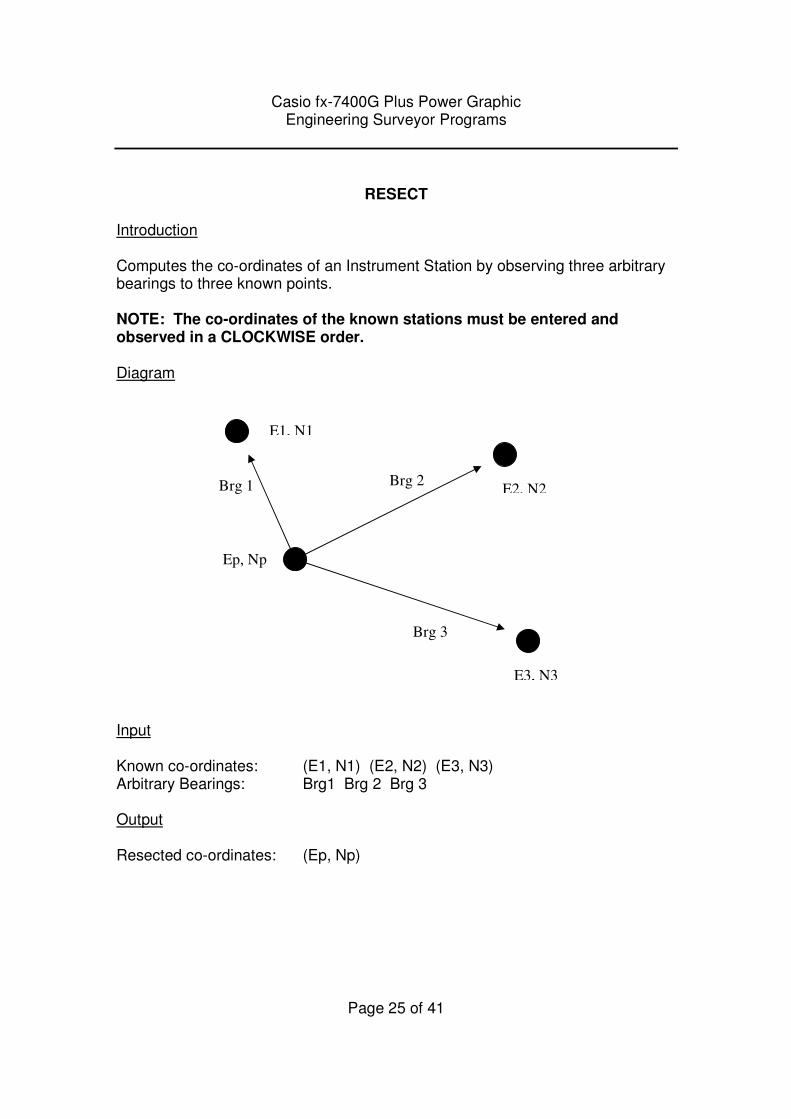
RESECT
Introduction Computes the co-ordinates of an Instrument Station by observing three arbitrary bearings to three known points. NOTE: The co-ordinates of the known stations must be entered and observed in a CLOCKWISE order. Diagram Input Known co-ordinates: (E1, N1) (E2, N2) (E3, N3) Arbitrary Bearings: Brg1 Brg 2 Brg 3 Output Resected co-ordinates: (Ep, Np)
Ep, Np
E1, N1
E2, N2
E3, N3
Brg 1 Brg 2
Brg 3
Casio fx-7400G Plus Power Graphic Engineering Surveyor Programs
Page 26 of 41
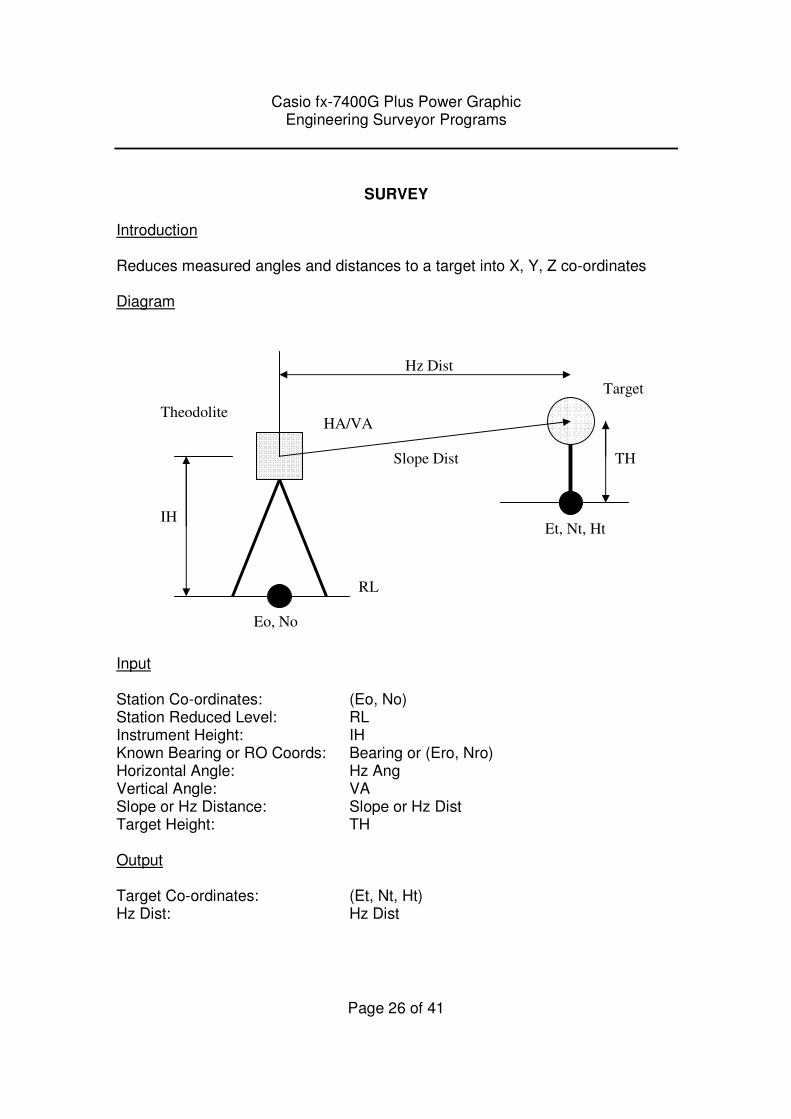
SURVEY
Introduction Reduces measured angles and distances to a target into X, Y, Z co-ordinates Diagram
Input Station Co-ordinates: (Eo, No) Station Reduced Level: RL Instrument Height: IH Known Bearing or RO Coords: Bearing or (Ero, Nro) Horizontal Angle: Hz Ang Vertical Angle: VA Slope or Hz Distance: Slope or Hz Dist Target Height: TH Output Target Co-ordinates: (Et, Nt, Ht) Hz Dist: Hz Dist
RL
IH
TH Slope Dist
Hz Dist
HA/VA
Et, Nt, Ht
Eo, No
Theodolite
Target
Casio fx-7400G Plus Power Graphic Engineering Surveyor Programs
Page 27 of 41
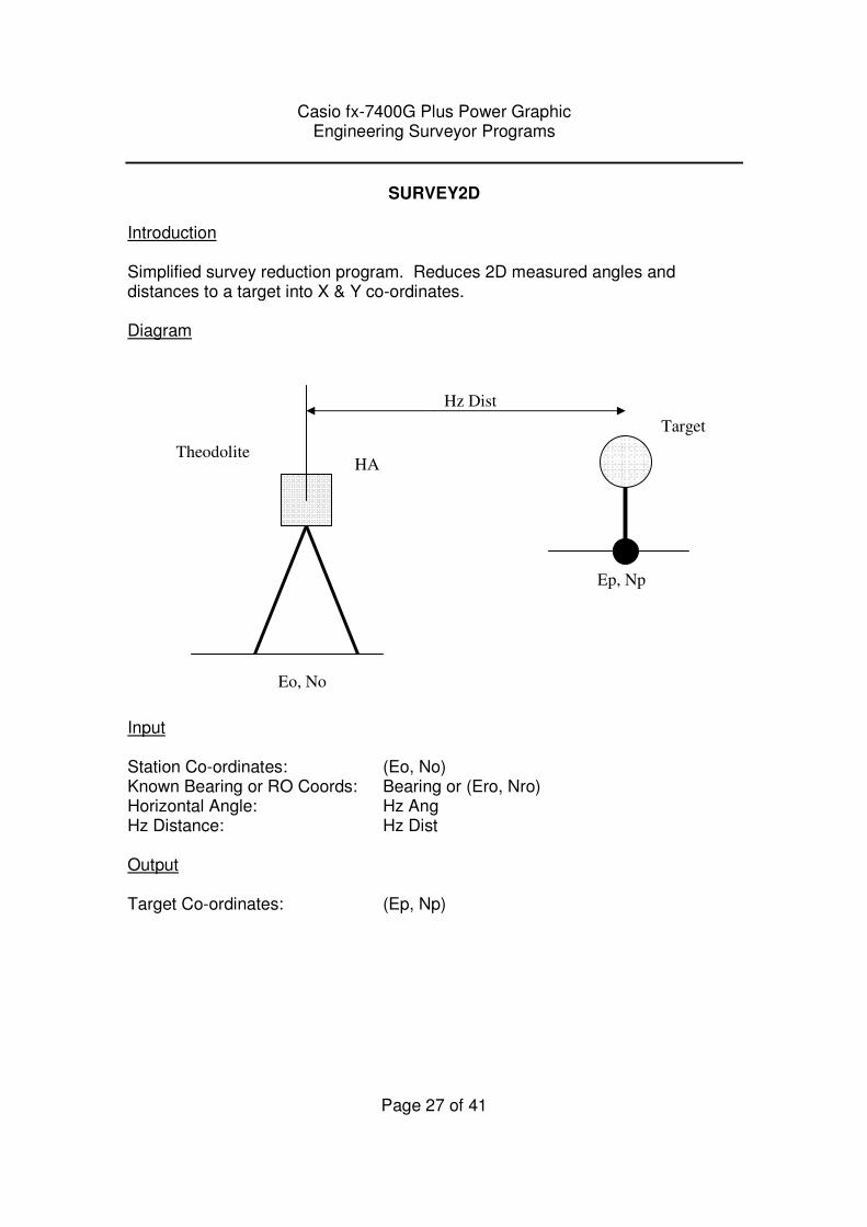
SURVEY2D Introduction Simplified survey reduction program. Reduces 2D measured angles and distances to a target into X & Y co-ordinates. Diagram
Input Station Co-ordinates: (Eo, No) Known Bearing or RO Coords: Bearing or (Ero, Nro) Horizontal Angle: Hz Ang Hz Distance: Hz Dist Output Target Co-ordinates: (Ep, Np)
Hz Dist
HA
Ep, Np
Eo, No
Theodolite
Target
Casio fx-7400G Plus Power Graphic Engineering Surveyor Programs
Page 28 of 41
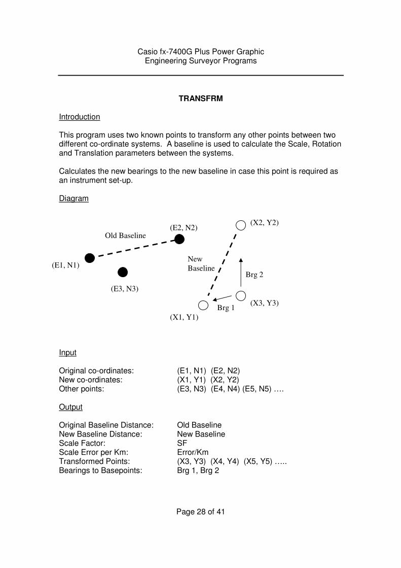
TRANSFRM
Introduction This program uses two known points to transform any other points between two different co-ordinate systems. A baseline is used to calculate the Scale, Rotation and Translation parameters between the systems. Calculates the new bearings to the new baseline in case this point is required as an instrument set-up. Diagram
Input Original co-ordinates: (E1, N1) (E2, N2) New co-ordinates: (X1, Y1) (X2, Y2) Other points: (E3, N3) (E4, N4) (E5, N5) …. Output Original Baseline Distance: Old Baseline New Baseline Distance: New Baseline Scale Factor: SF Scale Error per Km: Error/Km Transformed Points: (X3, Y3) (X4, Y4) (X5, Y5) ….. Bearings to Basepoints: Brg 1, Brg 2
(E1, N1)
(E2, N2)
(E3, N3)
(X2, Y2)
(X1, Y1)
(X3, Y3)
Old Baseline
New
Baseline
Brg 1
Brg 2
Casio fx-7400G Plus Power Graphic Engineering Surveyor Programs
Page 29 of 41
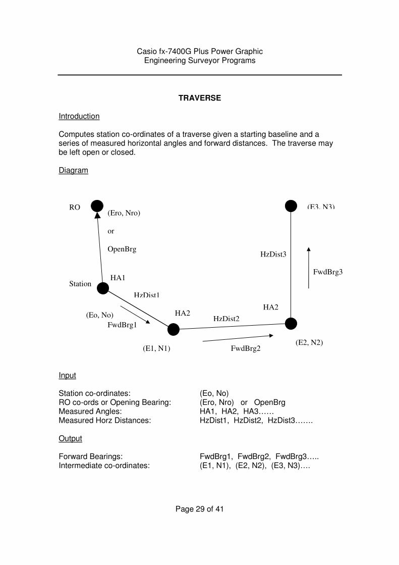
TRAVERSE
Introduction Computes station co-ordinates of a traverse given a starting baseline and a series of measured horizontal angles and forward distances. The traverse may be left open or closed. Diagram
Input Station co-ordinates: (Eo, No) RO co-ords or Opening Bearing: (Ero, Nro) or OpenBrg Measured Angles: HA1, HA2, HA3…… Measured Horz Distances: HzDist1, HzDist2, HzDist3……. Output Forward Bearings: FwdBrg1, FwdBrg2, FwdBrg3….. Intermediate co-ordinates: (E1, N1), (E2, N2), (E3, N3)….
(Ero, Nro)
or
OpenBrg
RO
(E1, N1) (E2, N2)
(E3, N3)
HzDist1
HzDist2
HzDist3
FwdBrg1
FwdBrg2
FwdBrg3 HA1
HA2 HA2
Station
(Eo, No)
Casio fx-7400G Plus Power Graphic Engineering Surveyor Programs
Page 30 of 41
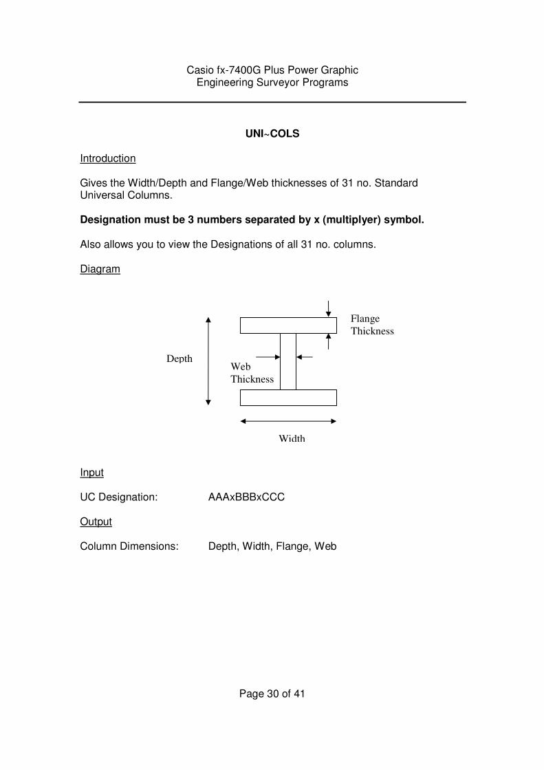
UNI~COLS
Introduction Gives the Width/Depth and Flange/Web thicknesses of 31 no. Standard Universal Columns. Designation must be 3 numbers separated by x (multiplyer) symbol. Also allows you to view the Designations of all 31 no. columns. Diagram
Input UC Designation: AAAxBBBxCCC Output Column Dimensions: Depth, Width, Flange, Web
Flange
Thickness
Depth
Width
Web
Thickness
Casio fx-7400G Plus Power Graphic Engineering Surveyor Programs
Page 31 of 41
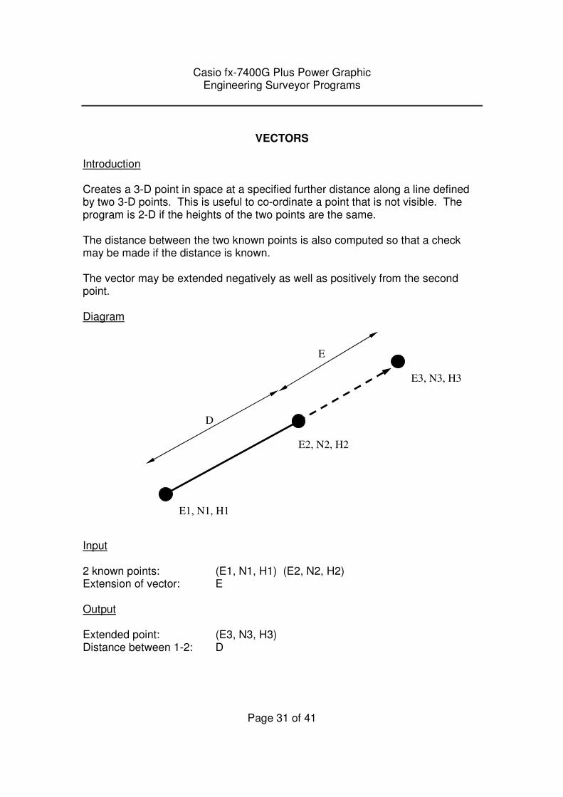
VECTORS
Introduction Creates a 3-D point in space at a specified further distance along a line defined by two 3-D points. This is useful to co-ordinate a point that is not visible. The program is 2-D if the heights of the two points are the same. The distance between the two known points is also computed so that a check may be made if the distance is known. The vector may be extended negatively as well as positively from the second point. Diagram Input 2 known points: (E1, N1, H1) (E2, N2, H2) Extension of vector: E Output Extended point: (E3, N3, H3) Distance between 1-2: D
E1, N1, H1
E2, N2, H2
E3, N3, H3
E
D
Casio fx-7400G Plus Power Graphic Engineering Surveyor Programs
Page 32 of 41
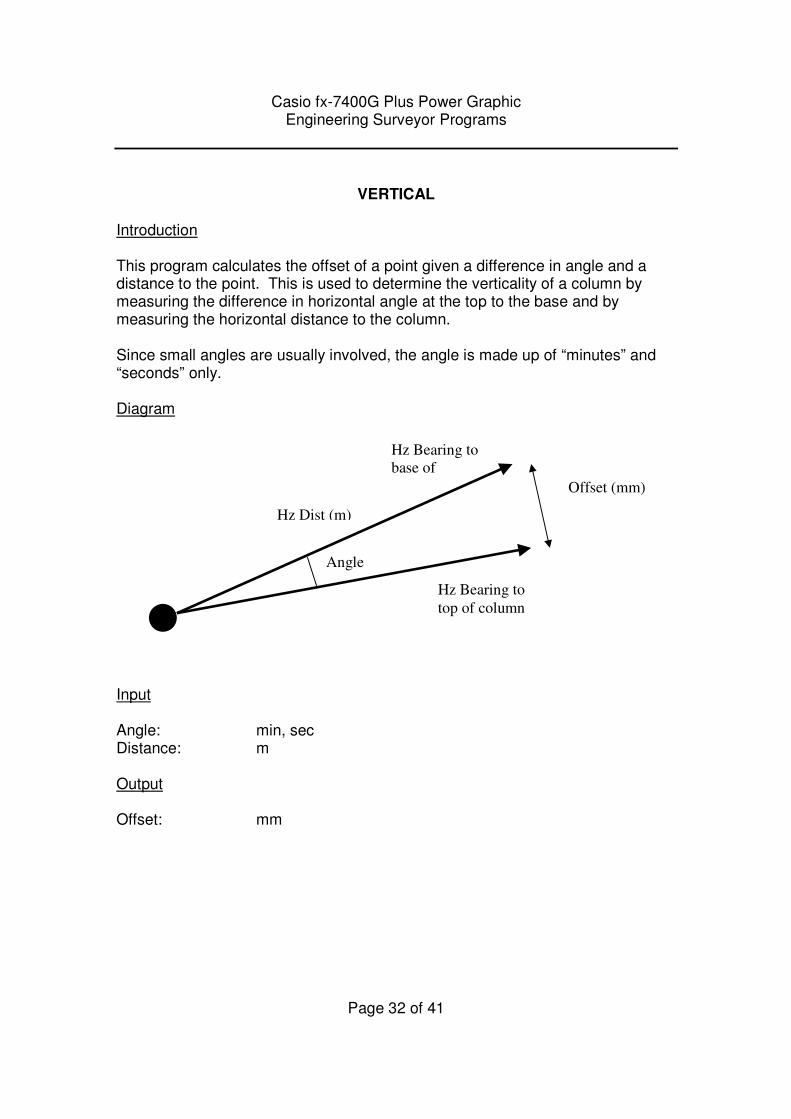
VERTICAL
Introduction This program calculates the offset of a point given a difference in angle and a distance to the point. This is used to determine the verticality of a column by measuring the difference in horizontal angle at the top to the base and by measuring the horizontal distance to the column. Since small angles are usually involved, the angle is made up of “minutes” and “seconds” only. Diagram Input Angle: min, sec Distance: m Output Offset: mm
Hz Bearing to
base of
column
Hz Bearing to
top of column
Offset (mm)
Angle
Hz Dist (m)
Casio fx-7400G Plus Power Graphic Engineering Surveyor Programs
Page 33 of 41
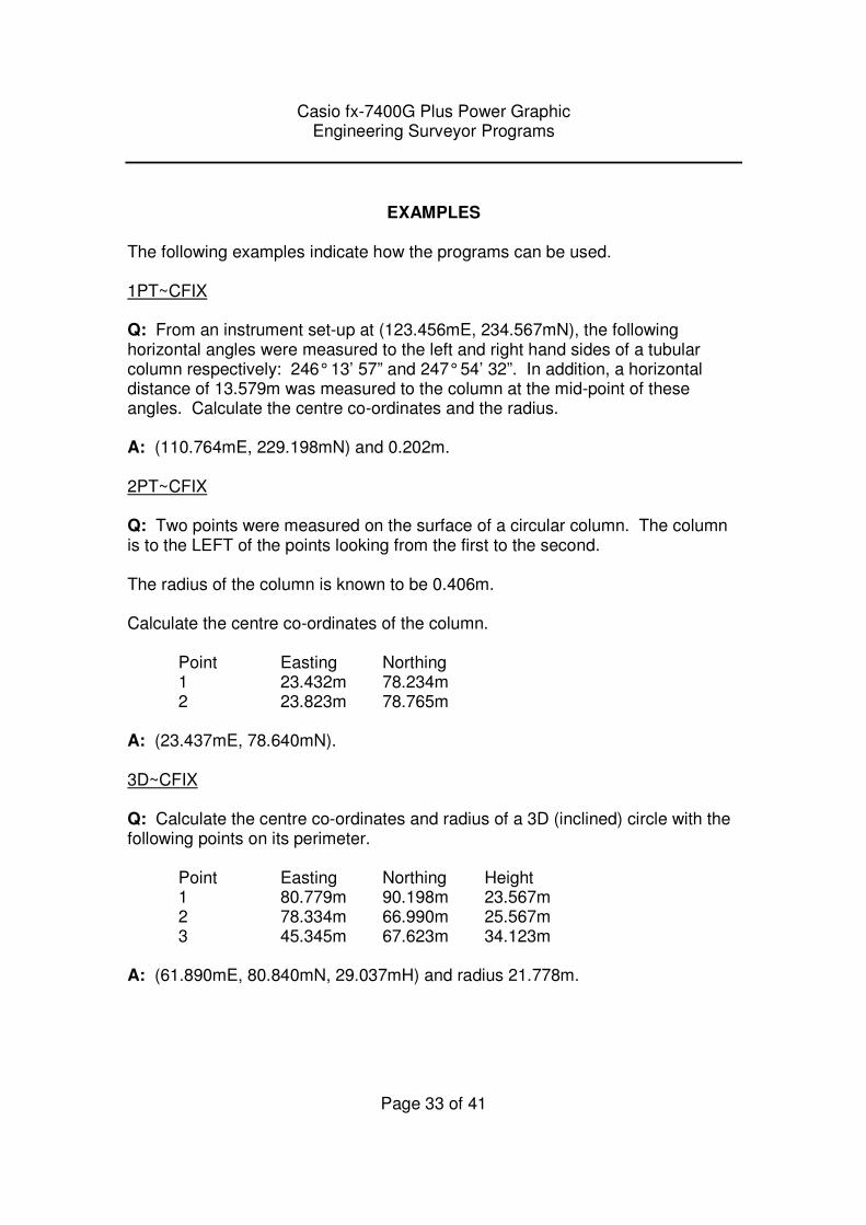
EXAMPLES
The following examples indicate how the programs can be used.
1PT~CFIX Q: From an instrument set-up at (123.456mE, 234.567mN), the following horizontal angles were measured to the left and right hand sides of a tubular column respectively: 246° 13’ 57” and 247° 54’ 32”. In addition, a horizontal distance of 13.579m was measured to the column at the mid-point of these angles. Calculate the centre co-ordinates and the radius. A: (110.764mE, 229.198mN) and 0.202m. 2PT~CFIX Q: Two points were measured on the surface of a circular column. The column is to the LEFT of the points looking from the first to the second. The radius of the column is known to be 0.406m. Calculate the centre co-ordinates of the column.
Point Easting Northing 1 23.432m 78.234m 2 23.823m 78.765m A: (23.437mE, 78.640mN). 3D~CFIX Q: Calculate the centre co-ordinates and radius of a 3D (inclined) circle with the following points on its perimeter.
Point Easting Northing Height 1 80.779m 90.198m 23.567m 2 78.334m 66.990m 25.567m 3 45.345m 67.623m 34.123m A: (61.890mE, 80.840mN, 29.037mH) and radius 21.778m.
Casio fx-7400G Plus Power Graphic Engineering Surveyor Programs
Page 34 of 41
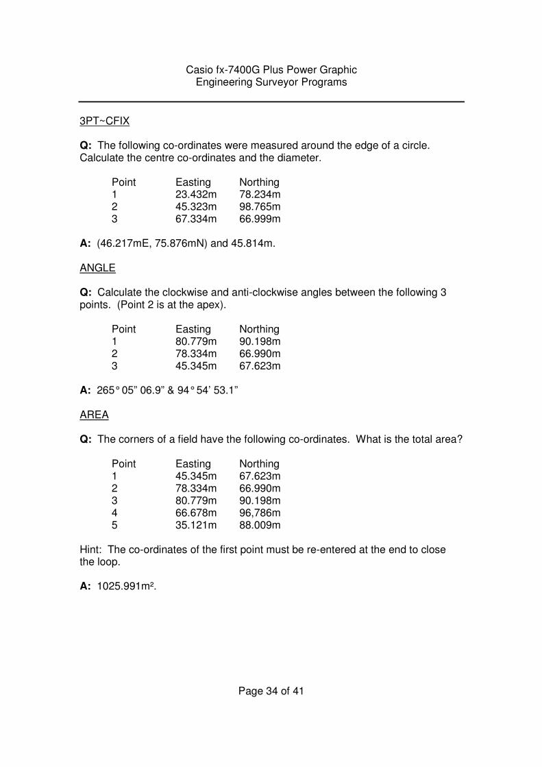
3PT~CFIX Q: The following co-ordinates were measured around the edge of a circle. Calculate the centre co-ordinates and the diameter. Point Easting Northing 1 23.432m 78.234m 2 45.323m 98.765m 3 67.334m 66.999m A: (46.217mE, 75.876mN) and 45.814m. ANGLE Q: Calculate the clockwise and anti-clockwise angles between the following 3 points. (Point 2 is at the apex). Point Easting Northing 1 80.779m 90.198m 2 78.334m 66.990m 3 45.345m 67.623m A: 265° 05” 06.9” & 94° 54’ 53.1” AREA Q: The corners of a field have the following co-ordinates. What is the total area? Point Easting Northing 1 45.345m 67.623m 2 78.334m 66.990m 3 80.779m 90.198m 4 66.678m 96,786m 5 35.121m 88.009m Hint: The co-ordinates of the first point must be re-entered at the end to close the loop. A: 1025.991m².
Casio fx-7400G Plus Power Graphic Engineering Surveyor Programs
Page 35 of 41
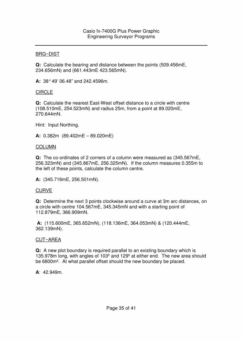
BRG~DIST Q: Calculate the bearing and distance between the points (509.456mE, 234.656mN) and (661.443mE 423.565mN). A: 38° 49’ 06.48” and 242.4596m. CIRCLE Q: Calculate the nearest East-West offset distance to a circle with centre (108.510mE, 254.523mN) and radius 25m, from a point at 89.020mE, 270.644mN. Hint: Input Northing. A: 0.382m (89.402mE – 89.020mE) COLUMN Q: The co-ordinates of 2 corners of a column were measured as (345.567mE, 256.323mN) and (345.867mE, 256.325mN). If the column measures 0.355m to the left of these points, calculate the column centre. A: (345.716mE, 256.501mN). CURVE Q: Determine the next 3 points clockwise around a curve at 3m arc distances, on a circle with centre 104.567mE, 345.345mN and with a starting point of 112.879mE, 366.909mN. A: (115.600mE, 365.652mN), (118.136mE, 364.053mN) & (120.444mE, 362.139mN). CUT~AREA Q: A new plot boundary is required parallel to an existing boundary which is 135.978m long, with angles of 103º and 129º at either end. The new area should be 6800m². At what parallel offset should the new boundary be placed. A: 42.949m.
Casio fx-7400G Plus Power Graphic Engineering Surveyor Programs
Page 36 of 41
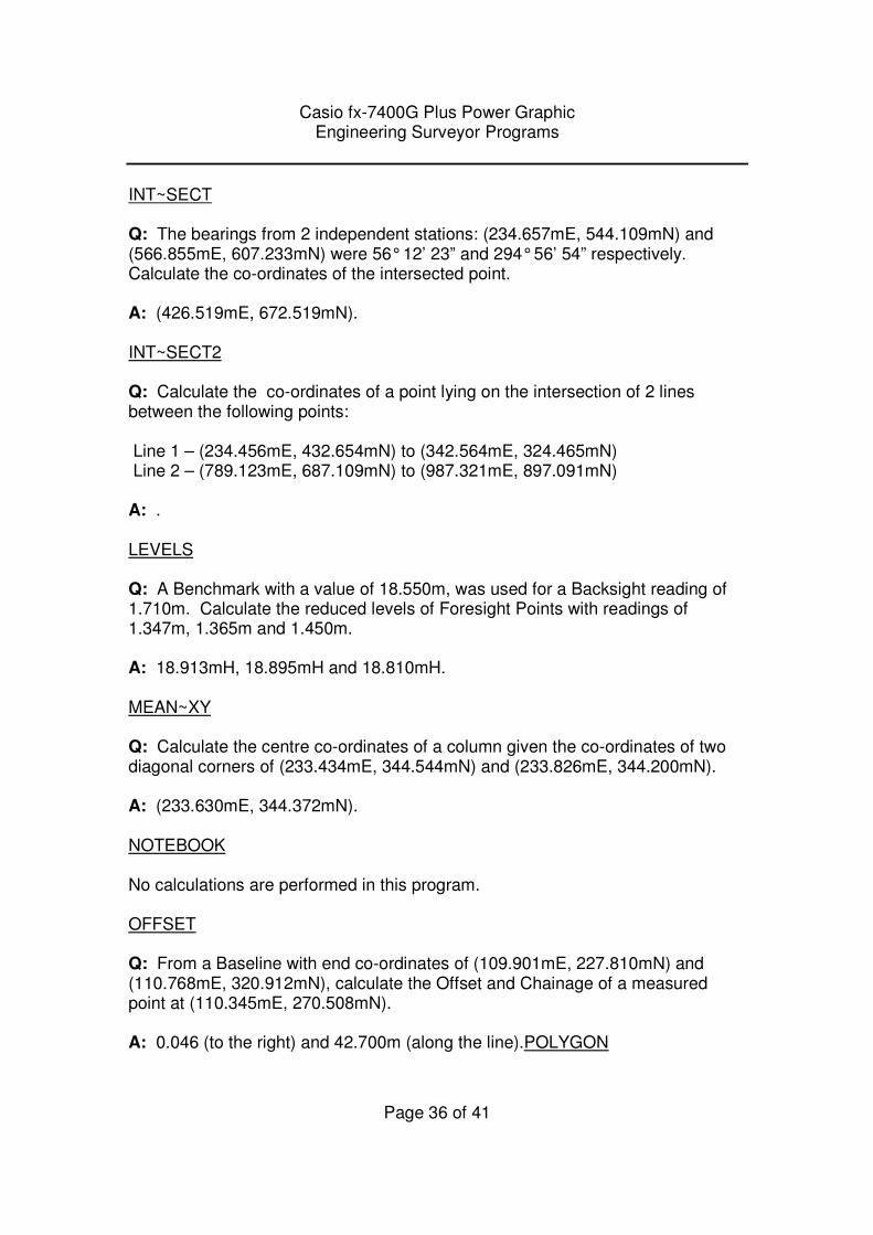
INT~SECT Q: The bearings from 2 independent stations: (234.657mE, 544.109mN) and (566.855mE, 607.233mN) were 56° 12’ 23” and 294° 56’ 54” respectively. Calculate the co-ordinates of the intersected point. A: (426.519mE, 672.519mN). INT~SECT2 Q: Calculate the co-ordinates of a point lying on the intersection of 2 lines between the following points: Line 1 – (234.456mE, 432.654mN) to (342.564mE, 324.465mN) Line 2 – (789.123mE, 687.109mN) to (987.321mE, 897.091mN) A: . LEVELS Q: A Benchmark with a value of 18.550m, was used for a Backsight reading of 1.710m. Calculate the reduced levels of Foresight Points with readings of 1.347m, 1.365m and 1.450m. A: 18.913mH, 18.895mH and 18.810mH. MEAN~XY Q: Calculate the centre co-ordinates of a column given the co-ordinates of two diagonal corners of (233.434mE, 344.544mN) and (233.826mE, 344.200mN). A: (233.630mE, 344.372mN). NOTEBOOK No calculations are performed in this program. OFFSET Q: From a Baseline with end co-ordinates of (109.901mE, 227.810mN) and (110.768mE, 320.912mN), calculate the Offset and Chainage of a measured point at (110.345mE, 270.508mN). A: 0.046 (to the right) and 42.700m (along the line).POLYGON
Casio fx-7400G Plus Power Graphic Engineering Surveyor Programs
Page 37 of 41
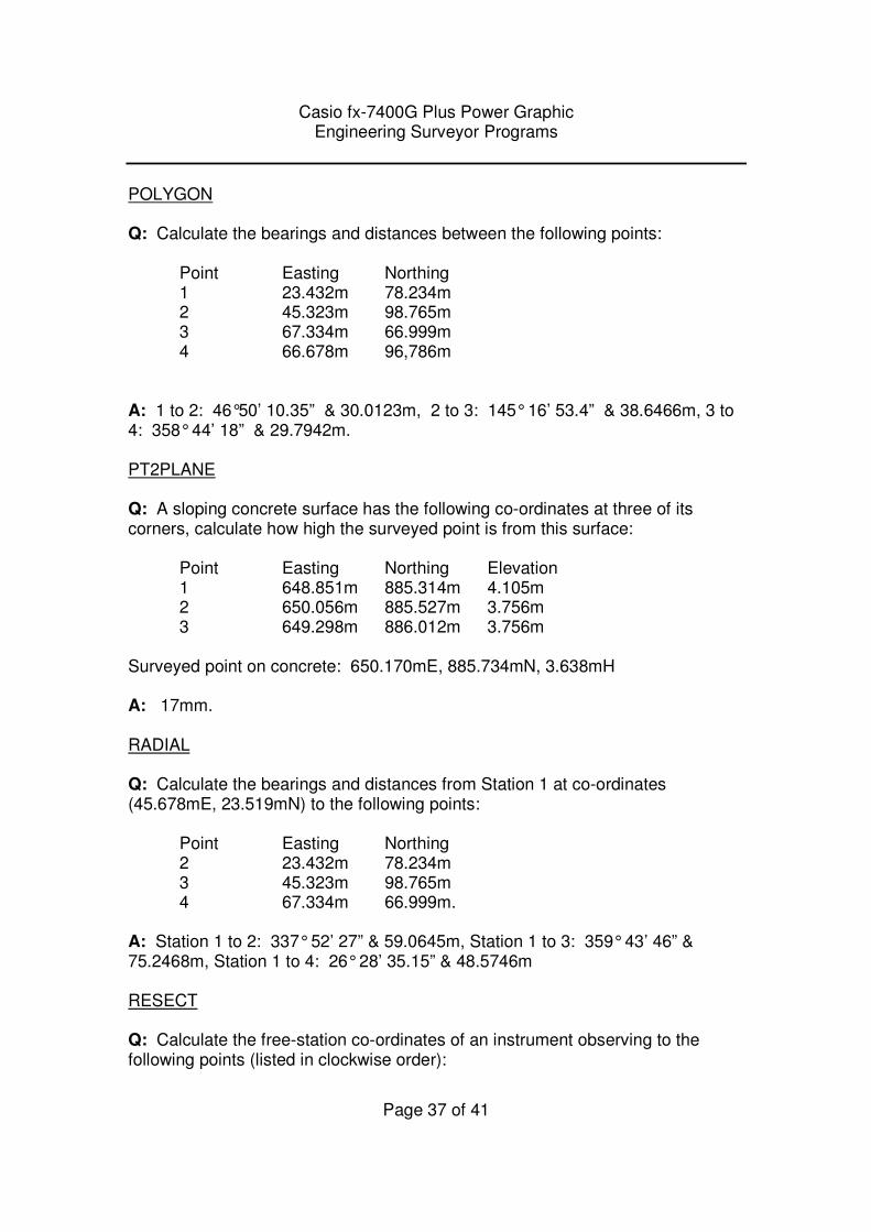
POLYGON Q: Calculate the bearings and distances between the following points: Point Easting Northing 1 23.432m 78.234m 2 45.323m 98.765m 3 67.334m 66.999m
4 66.678m 96,786m A: 1 to 2: 46°50’ 10.35” & 30.0123m, 2 to 3: 145° 16’ 53.4” & 38.6466m, 3 to 4: 358° 44’ 18” & 29.7942m. PT2PLANE Q: A sloping concrete surface has the following co-ordinates at three of its corners, calculate how high the surveyed point is from this surface: Point Easting Northing Elevation 1 648.851m 885.314m 4.105m 2 650.056m 885.527m 3.756m 3 649.298m 886.012m 3.756m Surveyed point on concrete: 650.170mE, 885.734mN, 3.638mH A: 17mm. RADIAL Q: Calculate the bearings and distances from Station 1 at co-ordinates (45.678mE, 23.519mN) to the following points: Point Easting Northing 2 23.432m 78.234m 3 45.323m 98.765m 4 67.334m 66.999m. A: Station 1 to 2: 337° 52’ 27” & 59.0645m, Station 1 to 3: 359° 43’ 46” & 75.2468m, Station 1 to 4: 26° 28’ 35.15” & 48.5746m RESECT Q: Calculate the free-station co-ordinates of an instrument observing to the following points (listed in clockwise order):
Casio fx-7400G Plus Power Graphic Engineering Surveyor Programs
Page 38 of 41
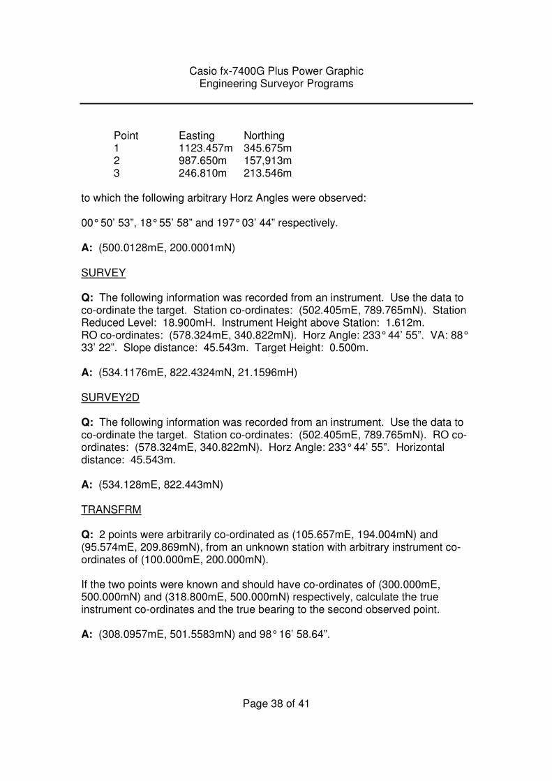
Point Easting Northing 1 1123.457m 345.675m 2 987.650m 157,913m 3 246.810m 213.546m to which the following arbitrary Horz Angles were observed: 00° 50’ 53”, 18° 55’ 58” and 197° 03’ 44” respectively. A: (500.0128mE, 200.0001mN) SURVEY Q: The following information was recorded from an instrument. Use the data to co-ordinate the target. Station co-ordinates: (502.405mE, 789.765mN). Station Reduced Level: 18.900mH. Instrument Height above Station: 1.612m. RO co-ordinates: (578.324mE, 340.822mN). Horz Angle: 233° 44’ 55”. VA: 88° 33’ 22”. Slope distance: 45.543m. Target Height: 0.500m. A: (534.1176mE, 822.4324mN, 21.1596mH) SURVEY2D Q: The following information was recorded from an instrument. Use the data to co-ordinate the target. Station co-ordinates: (502.405mE, 789.765mN). RO co-ordinates: (578.324mE, 340.822mN). Horz Angle: 233° 44’ 55”. Horizontal distance: 45.543m. A: (534.128mE, 822.443mN) TRANSFRM Q: 2 points were arbitrarily co-ordinated as (105.657mE, 194.004mN) and (95.574mE, 209.869mN), from an unknown station with arbitrary instrument co-ordinates of (100.000mE, 200.000mN). If the two points were known and should have co-ordinates of (300.000mE, 500.000mN) and (318.800mE, 500.000mN) respectively, calculate the true instrument co-ordinates and the true bearing to the second observed point. A: (308.0957mE, 501.5583mN) and 98° 16’ 58.64”.
Casio fx-7400G Plus Power Graphic Engineering Surveyor Programs
Page 39 of 41
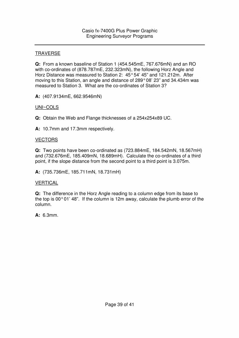
TRAVERSE Q: From a known baseline of Station 1 (454.545mE, 767.676mN) and an RO with co-ordinates of (878.787mE, 232.323mN), the following Horz Angle and Horz Distance was measured to Station 2: 45° 54’ 45” and 121.212m. After moving to this Station, an angle and distance of 289° 08’ 23” and 34.434m was measured to Station 3. What are the co-ordinates of Station 3? A: (407.9134mE, 662.9546mN) UNI~COLS Q: Obtain the Web and Flange thicknesses of a 254x254x89 UC. A: 10.7mm and 17.3mm respectively. VECTORS Q: Two points have been co-ordinated as (723.884mE, 184.542mN, 18.567mH) and (732.676mE, 185.409mN, 18.689mH). Calculate the co-ordinates of a third point, if the slope distance from the second point to a third point is 3.075m. A: (735.736mE, 185.711mN, 18.731mH) VERTICAL Q: The difference in the Horz Angle reading to a column edge from its base to the top is 00° 01’ 48”. If the column is 12m away, calculate the plumb error of the column. A: 6.3mm.
Casio fx-7400G Plus Power Graphic Engineering Surveyor Programs
Page 40 of 41
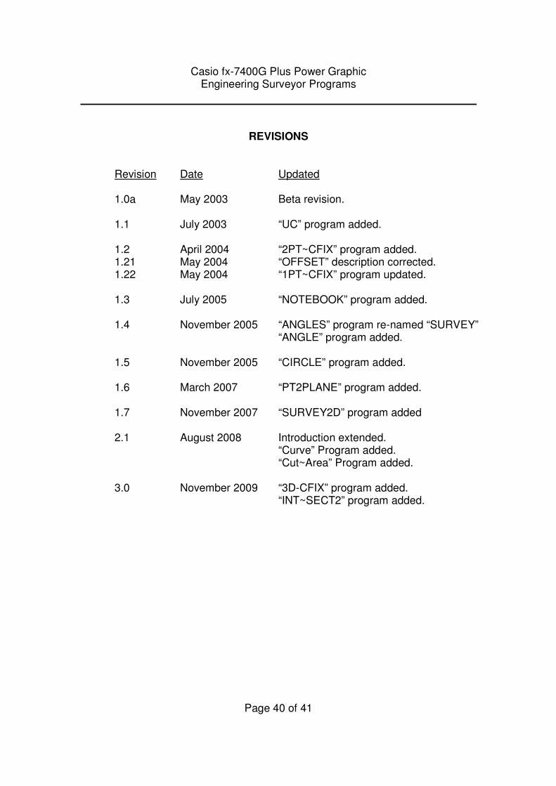
REVISIONS
Revision Date Updated
1.0a May 2003 Beta revision. 1.1 July 2003 “UC” program added. 1.2 April 2004 “2PT~CFIX” program added. 1.21 May 2004 “OFFSET” description corrected. 1.22 May 2004 “1PT~CFIX” program updated. 1.3 July 2005 “NOTEBOOK” program added. 1.4 November 2005 “ANGLES” program re-named “SURVEY” “ANGLE” program added.
1.5 November 2005 “CIRCLE” program added. 1.6 March 2007 “PT2PLANE” program added. 1.7 November 2007 “SURVEY2D” program added 2.1 August 2008 Introduction extended.
“Curve” Program added. “Cut~Area” Program added. 3.0 November 2009 “3D-CFIX” program added. “INT~SECT2” program added.

Casio fx-7400G Plus Power Graphic Engineering Surveyor Programs
Page 41 of 41
COPYRIGHT NOTICE
These programs MUST NOT be sold – collectively or individually, electronically as software or pre-installed on graphic calculators without the permission of the author. These programs may be distributed freely, but must maintain their copyright status.
© Mark Adams 2009 www.engineeringsurveyor.com