Embed Size (px)
Citation preview

CASE TOOLS & SOFTWARE TESTING
METHODOLOGIES LABORATORY
(R17A0589)
LAB MANUAL AND RECORD
B.TECH (III YEAR – II SEM)
(2019-2020)
DEPARTMENT OF INFORMATION TECHNOLOGY
MALLA REDDY COLLEGE OF ENGINEERING &
TECHNOLOGY (Autonomous Institution – UGC, Govt. of India)
Recognized under 2(f) and 12 (B) of UGC ACT 1956 Affiliated to JNTUH, Hyderabad, Approved by AICTE - Accredited by NBA & NAAC – ‘A’ Grade - ISO 9001:2015 Certified
Maisammaguda, Dhulapally (Post Via. Hakimpet), Secunderabad – 500100, Telangana State, India

DEPARTMENT OF INFORMATION TECHNOLOGY
Vision
To acknowledge quality education and instill high patterns of
discipline making the students technologically superior and ethically
strong which involves the improvement in the quality of life in human
race.
Mission
To achieve and impart holistic technical education using the best of
infrastructure, outstanding technical and teaching expertise to
establish the students into competent and confident engineers.
Evolving the center of excellence through creative and innovative
teaching learning practices for promoting academic achievement to
produce internationally accepted competitive and world class
professionals.

PROGRAMME EDUCATIONAL OBJECTIVES (PEOs)
PEO1 – ANALYTICAL SKILLS
To facilitate the graduates with the ability to visualize, gather information,
articulate, analyze, solve complex problems, and make decisions. These are essential to
address the challenges of complex and computation intensive problems increasing their
productivity.
PEO2 – TECHNICAL SKILLS
To facilitate the graduates with the technical skills that prepare them for
immediate employment and pursue certification providing a deeper understanding of the
technology in advanced areas of computer science and related fields, thus encouraging to
pursue higher education and research based on their interest.
PEO3 – SOFT SKILLS
To facilitate the graduates with the soft skills that include fulfilling the mission,
setting goals, showing self-confidence by communicating effectively, having a positive
attitude, get involved in team-work, being a leader, managing their career and their life.
PEO4 – PROFESSIONAL ETHICS
To facilitate the graduates with the knowledge of professional and ethical responsibilities
by paying attention to grooming, being conservative with style, following dress codes,
safety codes, and adapting themselves to technological advancements.

PROGRAM SPECIFIC OUTCOMES (PSOs)
After the completion of the course, B.Tech Information Technology, the graduates will have
the following Program Specific Outcomes:
1. Fundamentals and critical knowledge of the Computer System:- Able to
Understand the working principles of the computer System and its components ,
Apply the knowledge to build, asses, and analyze the software and hardware
aspects of it .
2. The comprehensive and Applicative knowledge of Software Development:
Comprehensive skills of Programming Languages, Software process models,
methodologies, and able to plan, develop, test, analyze, and manage the software
and hardware intensive systems in heterogeneous platforms individually or
working in teams.
3. Applications of Computing Domain & Research: Able to use the
professional, managerial, interdisciplinary skill set, and domain specific tools in
development processes, identify the research gaps, and provide innovative
solutions to them.

PROGRAM OUTCOMES (POs)
Engineering Graduates will be able to:
1. Engineering knowledge: Apply the knowledge of mathematics, science,
engineering fundamentals, and an engineering specialization to the solution of
complex engineering problems.
2. Problem analysis: Identify, formulate, review research literature, and analyze
complex engineering problems reaching substantiated conclusions using first
principles of mathematics, natural sciences, and engineering sciences.
3. Design / development of solutions: Design solutions for complex engineering
problems and design system components or processes that meet the specified
needs with appropriate consideration for the public health and safety, and the
cultural, societal, and environmental considerations.
4. Conduct investigations of complex problems: Use research-based knowledge
and research methods including design of experiments, analysis and
interpretation of data, and synthesis of the information to provide valid
conclusions.
5. Modern tool usage: Create, select, and apply appropriate techniques,
resources, and modern engineering and IT tools including prediction and
modeling to complex engineering activities with an understanding of the
limitations.
6. The engineer and society: Apply reasoning informed by the contextual
knowledge to assess societal, health, safety, legal and cultural issues and the
consequent responsibilities relevant to the professional engineering practice.
7. Environment and sustainability: Understand the impact of the professional
engineering solutions in societal and environmental contexts, and demonstrate
the knowledge of, and need for sustainable development.
8. Ethics: Apply ethical principles and commit to professional ethics and
responsibilities and norms of the engineering practice.
9. Individual and team work: Function effectively as an individual, and as a
member or leader in diverse teams, and in multidisciplinary settings.
10. Communication: Communicate effectively on complex engineering activities
with the engineering community and with society at large, such as, being able
to comprehend and write effective reports and design documentation, make
effective presentations, and give and receive clear instructions.
11. Project management and finance: Demonstrate knowledge and
understanding of the engineering and management principles and apply these
to one’s own work, as a member and leader in a team, to manage projects and
in multi disciplinary environments.
12. Life- long learning: Recognize the need for, and have the preparation and
ability to engage in independent and life-long learning in the broadest context
of technological change.

MALLA REDDY COLLEGE OF ENGINEERING & TECHNOLOGY Maisammaguda, Dhulapally Post, Via Hakimpet, Secunderabad – 500100
DEPARTMENT OF INFORMATION TECHNOLOGY
GENERAL LABORATORY INSTRUCTIONS
1. Students are advised to come to the laboratory at least 5 minutes before (to the
starting time), those who come after 5 minutes will not be allowed into the lab.
2. Plan your task properly much before to the commencement, come prepared to the lab
with the synopsis / program / experiment details.
3. Student should enter into the laboratory with:
a. Laboratory observation notes with all the details (Problem statement, Aim,
Algorithm, Procedure, Program, Expected Output, etc.,) filled in for the lab session.
b. Laboratory Record updated up to the last session experiments and other utensils
(if any) needed in the lab.
c. Proper Dress code and Identity card.
4. Sign in the laboratory login register, write the TIME-IN, and occupy the computer
system allotted to you by the faculty.
5. Execute your task in the laboratory, and record the results / output in the lab
observation note book, and get certified by the concerned faculty.
6. All the students should be polite and cooperative with the laboratory staff, must
maintain the discipline and decency in the laboratory.
7. Computer labs are established with sophisticated and high end branded systems,
which should be utilized properly.
8. Students / Faculty must keep their mobile phones in SWITCHED OFF mode during
the lab sessions. Misuse of the equipment, misbehaviors with the staff and systems
etc., will attract severe punishment.
9. Students must take the permission of the faculty in case of any urgency to go out ; if
anybody found loitering outside the lab / class without permission during working
hours will be treated seriously and punished appropriately.
10. Students should LOG OFF/ SHUT DOWN the computer system before he/she leaves
the lab after completing the task (experiment) in all aspects. He/she must ensure the
system / seat is kept properly.
Head of the Department Principal

Course Educational Objectives:
The objectives of this laboratory are:
1. Understand how UML supports the entire OOAD process.
2. Become familiar with all phases of OOAD.
3. Be able to understand the essential characteristics of tools used for designing a model.
4. Understand different software testing tools and their features
5. Manage the project from beginning to end
6. Define, formulate and analyze a problem
7. To learn how to write software testing documents, and communicate with engineers
invarious forms. To gain the techniques and skills on how to use modern software testing
tools to support software testing projects.
Course Outcomes:
Upon the completion of practical course Case tools & Software testing Lab, the student
will be able to attain the following things:
1. Able to understand the history, cost of using and building CASE tools.
2. Ability to construct and evaluate hybrid CASE tools by integrating existing tools.
3. Understand the myths and facts of software testing.
4. Analyze and design test cases using black box testing technique which includes
decision tables domain testing and transition testing.
5. Analyze and design test cases for a white box testing technique which includes path
testing, data flow graphs and matrix representation for a given problem.
6. Execute how to run test script wizard and Execute how to do performance testing using
testing tools including Selenium and JMeter respectively.
7. Demonstrate the importance of testing and its role in need of software development

CASE TOOLS & STM LIST OF PROGRAMS
S.No. Name of the
Experiment
Page No. Date Signature
1. Introduction to UML 1
2. Class Diagram for ATM 14
3. Use Case Diagram for ATM 20
4. Sequence Diagram for ATM 27
5. Collaboration Diagram for ATM 31
6. State chart Diagram for ATM 39
7. Activity Diagram for ATM 45
8. Component Diagram for ATM 52
9. Deployment Diagram for ATM 57
10. Write a programs in C language in
demonstration the working of the
following constructs i) do..while
ii) while..do iii) if…else iv)switch v)
for
62
11. A program for written in C language
for Matrix Multiplication fails‖
introspect the causes for its failure
and write down the possible reasons
for its failure
70
12. Write the test cases of functionalities
of ATM machine 75
13. Write the test cases for banking
application 83
14. Prepare a test plan
document for library
management system
91
15. Study of testing tool (e.g. Jmeter) 97
16. Study of web testing tool (e.g.
selenium) 110
17. Write a Test Cases for
a) Gmail application
b) b) Facebook Manually
128

Department of Information Technology Page 1
Introduction
CASE tools known as Computer-aided software engineering tools is a kind of
component- based development which allows its users to rapidly develop information
systems. The main goal of case technology is the automation of the entire information
systems development life cycle process using a set of integrated software tools, such as
modelling, methodology and automatic code generation. Component based
manufacturing has several advantages over custom development. The main advantages
are the availability of high quality, defect free products at low cost and at a faster time.
The prefabricated components are customized as per the requirements of the customers.
The components used are pre-built, ready-tested and add value and differentiation by
rapid customization to the targeted customers. However the products we get from case
tools are only a skeleton of the final product required and a lot of programming must be
done by hand to get a fully finished, good product. Characteristics of CASE:
Some of the characteristics of case tools that make it better than customized
development are;
It is a graphic oriented tool.
It supports decomposition of process. Some typical CASE tools are:
Unified Modeling Language
Data modeling tools, and
Source code generation tools
UNIFIED MODELING LANGUAGE
Introduction
The unified modeling language (UML) is a standard language for writing software blue
prints of the system.
Definition:
The UML is a language for
• Visualizing
• Specifying
• Constructing
• Documenting
the artifacts of a software system.

Department of Information Technology Page 2
• UML is a language that provides vocabulary and the rules for combing words in that
vocabulary for the purpose of communication.
• Vocabulary and rules of a language tell us how to create and real well formed models,
but they don‟t tell you what model you should create and when should create them.
Building Blocks of the UML:
The vocabulary of the UML encompasses three kinds of building blocks:
1. Things
2. Relationships
3. Diagrams
Things are abstractions that are first-class citizens in a model; Relationships tie these things
together;
Diagrams group interesting collections of things.
Things
Things are the most important building blocks of UML. There are four kinds of things in the UML.
1. Structural things
2. Behavioral things
3. Grouping things
4. Annotational things
1) STRUCTURAL THINGS:
Structural things are the nouns of the UML models.
These are static parts of the model, representing elements that are either
conceptual or physical.
There are seven kinds of Structural things.
1. Class
2. Interface
3. Collaboration
4. Use case
5. Active class
6. Component
7. Node

Department of Information Technology Page 3
mous eClicked() m
ous ePres sed() mous
eReleas ed() mous
eEntered() mous
eExited()
<<Interface>>
Mous eLis tener
(from event)
Login
Class:
A class is a description of a set of objects that shares the common attributes,
operations, relationships, and semantics. A class implements one or more
interfaces.Graphically, a class is represented as a rectangle, usually including its name,
attributes and operations, as shown below.
W in dow
ori gin
S ize
O pen() C
los e () Disp
l ay()
Interface:
An interface is a collection of operations that specify a service of a class or component. An
interface describes the externally visible behavior of that element.
Graphically the interface is rendered as a circle together with its name.
I Window
Collaboration:
Collaboration defines an interaction and is a society of roles and other elements that work
together to provide some cooperative behavior that‟s bigger than the sum of all the elements.
Graphically, collaboration is rendered as an ellipse with dashed lines, usually including only its
name as shown below.
Chain of
Responsibility
UseCase:
Use case is a description of a set of sequence of actions performed by a system for a specific
goal for the system.
Graphically, Use Case is rendered as an ellipse with dashed lines, usually including only its
name as shown below.

Department of Information Technology Page 4
ActiveClass:
An active class is a class whose objects own one or more processes or threads and therefore
can initiate control activity.
Graphically, an active class is rendered just like a class, but with heavy lines usually including
its name, attributes and operations as shown below.
Event
Management
Suspend()
Flush()
Component:
Component is a physical and replaceable part of a system that conforms to and provides the
realization of a set of interfaces.
Graphically, a component is rendered as a rectangle with tabs, usually including only its name,
as shown below.
orderform.java
Node:
A Node is a physical element that exists at run time and represents a computational resource,
generally having at least some memory and often, processing capability.
Graphically, a node is rendered as a cube, usually including only its name, as shown below.
2) BEHAVIORAL THINGS:
Behavioral things are the dynamic parts of UML models.
These are the verbs of a model, representing behavior over time and space.
server

Department of Information Technology Page 5
Business Rules
1) Interaction:
An interaction is a behavior that consists of a set of messages exchanged among a set of
objects(elements) within a particular context to accomplish a specific task.
Graphically, a message is rendered as a direct line, almost always including the name if its
operation, as shown below.
Display
2) State Machine:
A state machine is a behavior that specifies the sequence of states of an object in its life cycle.
It defines the sequence of states an object goes through in response to events.
Graphically, a state is rendered as a rounded rectangle usually including its name and its sub-
states, if any, as shown below.
Waiting
3) GROUPING THINGS:
Grouping things are the organizational parts of the UML models. These are the boxes into
which a model can be decomposed.
There is one primary kind of grouping thing with “package”.
Package:
A package is a general-purpose mechanism for organizing elements into groups.
Package is the only one grouping thing available for gathering structural and behavioral things.
Package
4) ANNOTATIONAL THINGS:
An notational things are the explanatory parts of the UML models.
An notational things can be defined as a mechanism to capture remarks, descriptions,
and comments of UML model elements.

Department of Information Technology Page 6
Note: A note is simply a symbol for rendering constraints and comments attached to an
element or a collection of elements.
Graphically a note is represented as a rectangle with dog-eared corner together, with a textual
or graphical comment, as shown below.
Note
RELATIONSHIPSINTHEUML:
Relationship is another most important building block of UML. It shows how elements
are associated with each other and this association describes the functionality of an
application. There are four kinds of relationships in the UML:
1. Dependency
2. Association
3. Generalization
4. Realization
Dependency
Dependency is a relationship between two things in which change in one element also
affects the other one.
Ex:
Dependency
Dependent Class
Independent Classs
Association:
Association is basically a set of links that connects elements of an UML model. It also
describes how many objects are taking part in that relationship.
1 Multipicity 1..n
A B
Rolename Rolename
Association

Department of Information Technology Page 7
1
Ex:Generalization:
Generalization can be defined as a relationship which connects a specialized element with a
generalized element. It basically describes inheritance relationship in the world of objects.
Ex:
Parent Class
Child Class1 Child Class2
Realization:
Realization can be defined as a relationship in which two elements are connected. One
element describes some responsibility which is not implemented and the other one
implements them. This relationship exists in case of interfaces.
Ex:
<<Interface>>
Remote TVSet
DIAGRAMSINUML:
All the elements, relationships are used to make a complete UML diagram and the diagram
represents a system.
The visual effect of the UML diagram is the most important part of the entire process.
Each UML diagram is designed to let developers and customers view a software system from a
different perspective and in varying degrees of abstraction.
UML diagrams are the ultimate output of the entire system.

Department of Information Technology Page 8
A diagram is the graphical presentation of a set of elements ,most often rendered as a
connected graph of vertices(things) arcs (relationships).
UML includes the following nine diagrams:
1) Class diagram
2) Object diagram
3) Use case diagram
4) Sequence diagram
5) Collaboration diagram
6) Activity diagram
7) State chart diagram
8) Deployment diagram
9) Component diagram
1. ClassDiagram
Class diagram is a diagram that shows a set of classes, interfaces, and collaborations
and their relationships. Class diagrams address the static design view or the static process
view of the system.
Graphically it is represented as follows:-
School Department
Student
2. ObjectDiagram
Object diagram shows a set of objects and their relationships. These diagram the static design
view or static process view of a system.
3. UsecaseDiagram
Use Case diagram shows a set of use cases and actors (a special kind of class) and their relationships.
These diagrams address the static use case view of a system. Graphically it is represented as follows:-
User Book Issue

Department of Information Technology Page 9
drinkWater()
closeBottle()
4. SequenceDiagram
Sequence diagram are interaction diagrams. This diagram emphasizes the time-
ordering of messages. These diagrams address the dynamic view of a system. Sequence
Diagram displays the time sequence of the objects participating in the interaction. This
consists of the vertical dimension (time) and horizontal dimension (different
objects).Graphically it is represented as
follows:-
:Bottle
openBottle()
5 Collaboration Diagram
Collaboration diagram are also interaction diagrams. These diagrams emphasizes the structural
organization of the objects that send and receive messages. These diagrams address the dynamic
view of a system. Collaboration Diagram displays an interaction organized around the objects
and their links to one another. Numbers are used to show the sequence of messages.Graphically
it is
represented as follows:-
2: drinkWater()
:Bottle :Person
1: openBottle()
3: closeBottle()
6. Statechart Diagram
State chart diagram shows a state machine, consisting of states, transitions, events and
activities. These diagrams address the dynamic view of the system. State Chart diagram
displays the sequences of states that an object of an interaction goes through during its life in
response to received stimuli, together with its responses and actions.
7 .Activity Diagram
Activity diagram is a special kind of a state chart diagram that shows the flow from activity to activity
within a system. These diagrams address dynamic view of a system. Activity Diagram displays a special
:Person

Department of Information Technology Page 10
fraudagent.dll
Admin Client
admin.exe
state diagram where most of the states are action states and most of the transitions are triggered by
completion of the actions in the source states. Graphically it is represented as follows:-
8. ComponentDiagram
Component diagram shows the organizations and dependencies among a set of
components. These diagrams address the static implementation of view of a system. Component
Diagram displays the high level packaged structure of the code itself. Dependencies among
components are shown, including source code components, binary code components, and
executable components. Some components exist at compile time, at link time, at run times well
as at more
than one time.Graphically it is represented as follows:-
fraudagent.exe
9. Deployment Diagram
Deployment diagram shows the configuration of run-time processing nodes and the components that
live on them. These diagrams address the static deployment view of architecture. Deployment Diagram
displays the configuration of run-time processing elements and the software components, processes,
and objects that live on them. Software component instances represent run-time
manifestations of code.
Graphically it is represented as follows:-
<<10-T Ethernet>>
<<RS-232>>
Exam Client
exam.exe
Server

Department of Information Technology Page 11
Experiment 1
ATM System

Department of Information Technology Page 12
Automatic Teller Machine (ATM)
Description of ATM System
The software to be designed will control a simulated automated teller machine (ATM) having a
magnetic stripe reader for reading an ATM card, a customer console (keyboard and display) for
interaction with the customer, a slot for depositing envelopes, a dispenser for cash, a printer for
printing customer receipts, and a key-operated switch to allow an operator to start or stop the machine.
The ATM will communicate with the bank‟s computer over an appropriate communication link. (The
software on the latter is not part of the requirements for this problem.)
The ATM will service one customer at a time. A customer will be required to insert an ATM card
and enter a personal identification number (PIN) – both of which will be sent to the bank for validation
as part of each transaction. The customer will then be able to perform one or more transactions. The
card will be retained in the machine until the customer indicates that he/she desires no further
transactions, at which point it will be returned – except as noted below.
The ATM must be able to provide the following services to the customer:
1. A customer must be able to make a cash withdrawal from any suitable account linked to the
card. Approval must be obtained from the bank before cash is dispensed.
2. A customer must be able to make a deposit to any account linked to the card, consisting of cash
and/or checks in an envelope. The customer will enter the amount of the deposit into the ATM,
subject to manual verification when the envelope is removed from the machine by an operator.
Approval must be obtained from the bank before physically accepting the envelope.
3. A customer must be able to make a transfer of money between anytwo accounts linked to the
card.
4. A customer must be able to make a balance inquiry of any account linked to thecard.
5. A customer must be able to abort a transaction in progress bypressing the Cancel key instead
of responding to a request from the machine.
The ATM will communicate each transaction to the bank and obtain verification that it was
allowed by the bank. Ordinarily, a transaction will be considered complete by the bank once it has
been approved. In the case of a deposit, a second message will be sent to the bank indicating that the
customer has deposited the envelope. (If the customer fails to deposit the envelope within the timeout
period, or presses cancel instead, no second message will be sent to the bank and the deposit will not
be credited to the customer.)

Department of Information Technology Page 13
If the bank determines that the customer‟s PIN is invalid, the customer will be required to re-enter
the PIN before a transaction can proceed. If the customer is unable to successfully enter the PIN after
three tries, the card will be permanently retained by the machine, and the customer will have to contact
the bank to get it back.
If a transaction fails for any reason other than an invalid PIN, the ATM will display an
explanation of the problem, and will then ask the customer whether he/she wants to do another
transaction.
The ATM will provide the customer with a printed receipt for each successful transaction,
showing the date, time, machine location, type of transaction, account(s), amount, and ending and
available
balance(s) of the affected account (“to” account for transfers).
The ATM will have a key-operated switch that will allow an operator to start and stop the
servicing of customers. After turning the switch to the “on” position, the operator will be required to
verify and enter the total cash on hand. The machine can only be turned off when it is not servicing a
customer. When the switch is moved to the “off” position, the machine will shut down, so that the
operator may remove deposit envelopes and reload the machine with cash, blank receipts, etc.
Objectives
The objective of this software is similar to ATM software installed in ATM center. It should
first validate the pin in the ATM card. Then the type of transaction is enquired and the information
from the customer is validated. If it is a withdrawal the amount is asked. After the money is delivered
the transaction just made is updated in the database where the customer‟s information is stored.
Scope
The scope of the project is to design an ATM system that will help in completely automatic
banking this software is going to be designed for withdrawal and deposit of money and register the
transaction in the database where the customer‟s information is stored.

Department of Information Technology Page 14
A) Name of the experiment: Class diagram for ATM System
1. AIM: To design and implement ATM system through Class Diagram
Purpose:
The purpose of the class diagram is to model the static view of an application. The class diagrams
are the only diagrams which can be directly mapped with object oriented languages and thus widely
used at the time of construction. The UML diagrams like activity diagram, sequence diagram can only
give the sequence flow of the application but class diagram is a bit different. So it is the most popular
UML diagram in the coder community. So the purpose of the class diagram can be summarized as:
• Analysis and design of the static view of an application.
• Describe responsibilities of a system.
• Base for component and deployment diagrams.
• Forward and reverse engineering.
Contents:
Class diagrams commonly contain the following things
• Classes
• Interfaces
• Collaborations
• Dependency, generalization and association relationships
Procedure:-
Step1: First Classes are created.
Step2: Named as PinValid, Account Type, Transaction, Update, Server, Customer classes are
created.
Step3: Appropriate relationships are provided between them as association.

Department of Information Technology Page 15
DIAGRAM:
Inferences:
1. understand the concept of classes
2. identify classes and attributes and operations for a class
3. model the class diagram for the system
Applications:
Online transaction
Online banking

Department of Information Technology Page 16
RECORD NOTES

Department of Information Technology Page 17
RECORD NOTES

Department of Information Technology Page 18
RECORD NOTES

Department of Information Technology Page 19
RECORD NOTES

Department of Information Technology Page 20
B) NAME OF EXPERIMENT: Use case diagram for ATMSystem.
AIM: To design and implement ATM System through Use case Diagram.
Purpose:
The purpose of use case diagram is to capture the dynamic aspect of a system. Because other
four diagrams (activity, sequence, collaboration and State chart) are also having the same purpose.
So we will look into some specific purpose which will distinguish it from other four diagrams. Use
case diagrams are used to gather the requirements of a system including internal and external
influences. These requirements are mostly design requirements. So when a system is analyzed to
gather its functionalities use cases are prepared and actors are identified.
So in brief, the purposes of use case diagrams can be as follows:
• Used to gather requirements of a system.
• Used to get an outside view of a system.
• Identify external and internal factors influencing the system.
• Show the interacting among the requirements are actors.
Procedure:
Step1: First an Actor is Created and named as User/Customer.
Step2: Secondly a system is created for ATM.
Step3: A use case Enter PIN, Withdraw money is created and connected with user as association relationship.
Step4: Similarly various use cases like Deposit money, Balance Enquiry, Manage Account etc are
created and appropriate relationships are associated with each of them.

Department of Information Technology Page 21
DIAGRAM:
Enter PIN
Withdraw Money
Balance enquiry
Customer
Deposit
Abort/ Cancel
Print Receipt
Manage Account
ATMadmin
Withdrawal UseCase
A withdrawal transaction asks the customer to choose a type of account to withdraw from (e.g.
checking) from a menu of possible accounts, and to choose an amount from a menu of possible
amounts. The system verifies that it has sufficient money on hand to satisfy the request before sending
the transaction to the bank. (If not, the customer is informed and asked to enter a different amount.) If
the transaction is approved by the bank, the appropriate amount of cash is dispensed by the machine
before it issues a receipt. A withdrawal transaction can be cancelled by the customer pressing the
Cancel key any time prior to choosing the amount.
Deposit UseCase
A deposit transaction asks the customer to choose a type of account to deposit to (e.g. checking)
from a menu of possible accounts, and to type in amount on the keyboard. The transaction is initially
sent to the bank to verify that the ATM can accept a deposit from this customer to this account. If the

Department of Information Technology Page 22
transaction is approved, the machine accepts an envelope from the customer containing cash and/or
checks before it issues a receipt. Once the envelope has been received, a second message is sent to the
bank, to confirm that the bank can credit the customer‟s account – contingent on manual verification
of the deposit envelope contents by an operator later.
A deposit transaction can be cancelled by the customer pressing the Cancel key any time prior
to inserting the envelope containing the deposit. The transaction is automatically cancelled if the
customer fails to insert the envelope containing the deposit within a reasonable period of time after
being asked to do so.
InquiryUseCase
An inquiry transaction asks the customer to choose a type of account to inquire about from a
menu of possible accounts. No further action is required once the transaction is approved by the bank
before printing the receipt. An inquiry transaction can be cancelled by the customer pressing the
Cancel key any time prior to choosing the account to inquire about.
ValidateUserUsecase:
This use case is for validate the user i.e. check the pin number, when the bank reports that the
customer‟s transaction is disapproved due to an invalid PIN. The customer is required to re-enter the
PIN and the original request is sent to the bank again. If the bank now approves the transaction, or
disapproves it for some other reason, the original use case is continued; otherwise the process of re-
entering the PIN is repeated. Once the PIN is successfully re-entered
If the customer fails three times to enter the correct PIN, the card is permanently retained, a
screen is displayed informing the customer of this and suggesting he/she contact the bank, and the
entire customer session is aborted.
PrintBillusecase
This usecase is for printing corresponding bill after transactions (withdraw or deposit, or
balance enquiry, transfer) are completed.
ManageAccount
This use case is for updating corresponding user accounts after transactions (withdraw or
deposit or transfer) are completed.

Department of Information Technology Page 23
RESULT:
Inferences:
1. Identification of use cases. 2. Identification of actors.
INTERACTIONDIAGRAMS
We have two types of interaction diagrams in UML. One is sequence diagram and the other is
a collaboration diagram. The sequence diagram captures the time sequence of message flow from one
object to another and the collaboration diagram describes the organization of objects in a system
taking part in the message flow.
So the following things are to be identified clearly before drawing the interaction diagram:
1. Objects taking part in the interaction.
2. Message flows among the objects.
3. The sequence in which the messages are flowing.
4. Object organization.
Purpose:
1. To capture dynamic behavior of a system.
2. To describe the message flow in the system.
3. To describe structural organization of the objects.
4. To describe interaction among objects.
Contents of a Sequence Diagram
Objects
Focus of control
Messages
Life line
Contents of a Collaboration Diagram
Objects
Links
Messages

Department of Information Technology Page 24
RECORD NOTES

Department of Information Technology Page 25
RECORD NOTES

Department of Information Technology Page 26
RECORD NOTES

Department of Information Technology Page 27
C) NAME OF EXPERIMENT: Sequence diagram for ATMSystem.
AIM: To design and implement ATM System through Sequence Diagram.
Procedure:-
Step1: First An actor is created and named as user.
Step2: Secondly an object is created for Atm.
Step3: Timelines and lifelines are created automatically for them.
Step4: In sequence diagram interaction is done through time ordering of messages. So appropriate
messages are passed between user and ATM is as shown in the figure.
DIAGRAM:
check pin no
pin valid/invalid
check account
display status
check amount
display status
Update account
ATM ADMIN
Department of Information Technology Page 28
RECORD NOTES

Department of Information Technology Page 29
RECORD NOTES

Department of Information Technology Page 30
RECORD NOTES

Department of Information Technology Page 31
AT
D) NAME OF EXPERIMENT: collaboration for ATM System.
AIM: To design and implement ATM System through Collaboration diagram.
Procedure:-
Step1: First an actor is created and named as user.
Step2: Secondly an object is created for ATM.
Step3: In collaboration diagram interaction is done through organization.
Step4: So appropriate messages are passed between user and ATM as shown in the figure.
DIAGRAM:
1: check pin no
3: check account
5: check amount
7: update account
M
2: pin valid/invalid
4: display status
6: display status
ADMIN
Department of Information Technology Page 32
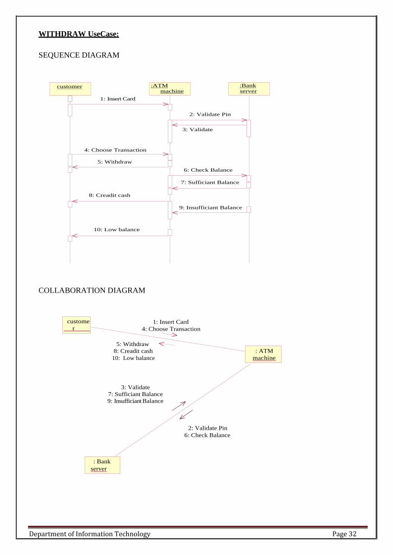
WITHDRAW UseCase:
SEQUENCE DIAGRAM
1: Insert Card
:ATM
machine
:Bank server
2: Validate Pin
3: Validate
4: Choose Transaction
5: Withdraw
6: Check Balance
7: Sufficiant Balance
8: Creadit cash
9: Insufficiant Balance
10: Low balance
COLLABORATION DIAGRAM
1: Insert Card
4: Choose Transaction
5: Withdraw
8: Creadit cash
10: Low balance
3: Validate
7: Sufficiant Balance
9: Insufficiant Balance
2: Validate Pin
6: Check Balance
customer
: Bank
server
: ATM
machine
custome
r

Department of Information Technology Page 33
ENQUIRY UseCase:
SEQUENCE DIAGRAM:
customer
1: Insert Card
:session :Bank
server
2: Obtain Pin
3: Enter Pin
4: Send Pin
5: Request
6: Obtain types of enquiry
7: Type
8: Get a/c no's
9: seif
10: Bal enquiry
11: Current bal
12: Transaction history
13: Previous trans
14: Viewa/c details
15: Display(a/c no,bal,names)

Department of Information Technology Page 34
COLLABARATION DIAGRAM:
1: Insert Card
7: Type
3: Enter Pin
5: Request 6: Obtain types of enquiry
9: seif
11: Current bal
13: Previous trans 15: Display(a/c no,bal,names)
2: Obtain Pin 4: Send Pin
8: Get a/cno's 10: Bal enquiry
12: Transactionhistory 14: View a/c details
DEPOSIT UseCase:
SEQUENCE DIAGRAM:
customer :ATM
machine :Bank server
1: Insert card
2: Obtain Pin
3: Enter Pin
4: Validate Pin
5: Valid Pin
6: Enter deposit amt
9: Insert Envelop amt slot
10: Envelop recived
8: Open deposit slot
7: Deposit Amt
: Bank
server
:session
custome
r

Department of Information Technology Page 35
COLLABARATION DIAGRAM:
1: Insert card
3: Enter Pin 7: Deposit Amt
2: Obtain Pin
6: Enter deposit amt
8: Open deposit slot
9: Insert Envelop amt slot
10: Envelop recived
5: Valid Pin 4: Validate Pin
STATECHART Diagram
State Chart diagram is used to model dynamic nature of a system. They define different states
of an object during its lifetime. And these states are changed by events. State chart diagram
describes the flow of control from one state to another state.
States are defined as a condition in which an object exists and it changes when some event is
triggered. But the main purpose is to model reactive system.
Contents
• Simply state and composite states
• Transitions, including events and actions
: Bank
server
: ATM
machine
custome
r

Department of Information Technology Page 36
RECORD NOTES

Department of Information Technology Page 37
RECORD NOTES

Department of Information Technology Page 38
RECORD NOTES

Department of Information Technology Page 39
E) NAME OF EXPERIMENT: State chart diagram for ATMSystem.
AIM: To design and implement ATM System through State Chart diagram.
Purpose:
Following are the main purposes of using State chart diagrams:
1. To model dynamic aspect of a system.
2. To model life time of a reactive system.
3. To describe different states of an object during its life time.
4. Defines a state machine to model states of an object.
Procedure:-
Step1: First after initial state control undergoes transition to ATM screen.
Step2: After inserting card it goes to the state wait for pin.
Step3: After entering pin it goes to the state account verification.
Step4:. In this way it undergoes transitions to various states and finally reaches the ATM screen state
as shown in the fig.

Department of Information Technology Page 40
DIAGRAM:
STATE CHART DIAGRAM

Department of Information Technology Page 41
STATE CHART FOR ATM
idle enter/pressed ready
press [first digit>0]
next
number
enter/pressed validate invalid
valid
transactions cancel pressed cancel
complete cancelled

Department of Information Technology Page 42
RECORD NOTES

Department of Information Technology Page 43
RECORD NOTES

Department of Information Technology Page 44
RECORD NOTES

Department of Information Technology Page 45
F) NAME OF EXPERIMENT: Activity diagram for ATM System.
AIM: To design and implement ATM System through Activity Diagram.
THEORY: An activity diagram shows the flow from activity to activity .An activity is an ongoing non
atomic execution within a state machine .Activities ultimately results in some action, which is made up
of executable atomic computations. We can use these diagrams to model the dynamic aspects of a
system.
Activity diagram is basically a flow chart to represent the flow form one activity to another . The
activity can be described as an operation of the system. So the control flow is drawn from one
operation to another. This flow can be sequential, branched or concurrent. Activity diagrams deals
with all type of flow by using elements like fork, join etc.
Contents
Initial/Final State, Activity, Fork & Join, Branch, Swim lanes

Department of Information Technology Page 46
Fork
A fork represents the splitting of a single flow of control into two or more concurrent Flow of control.
A fork may have one incoming transition and two or more outgoing transitions, each of which
represents an independent flow of control. Below fork the activities associated with each of these path
continues in parallel.
Join
A join represents the synchronization of two or more concurrent flows of control. A join may have
two or more incoming transition and one outgoing transition. Above the join the activities associated
with each of these paths continues in parallel.
Branching
A branch specifies alternate paths takes based on some Boolean expression Branch is represented by
diamond Branch may have one incoming transition and two or more outgoing one on each outgoing
transition, you place a Boolean expression shouldn‟t overlap but they should cover all possibilities.
Swimlane:
Swimlanes are useful when we model workflows of business processes to partition the activity states
on an activity diagram into groups. Each group representing the business organization responsible for
those activities, these groups are called Swimlanes .
Procedure:-
Step1: First initial state is created.
Step2: After that it goes to the action state insert card.
Step3: Next it undergoes transition to the state enter pin
Step4: In this way it undergoes transitions to the various states.
Step5: Use forking and joining wherever necessary.
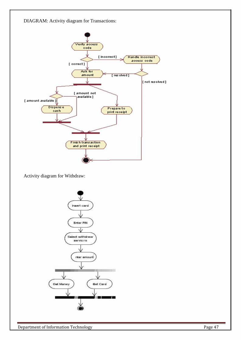
Department of Information Technology Page 47
DIAGRAM: Activity diagram for Transactions:
Activity diagram for Withdraw:

Department of Information Technology Page 48
customer ATM bank serv er
insert card
enter PIN validate PIN
select
transaction
receive cash
:receipt
start transaction :validation
[success]
:transaction
withdraw
close
transaction
Inferences:
1. Identify the action states of the objects .
2. Understand the transitions and events for various objects.

Department of Information Technology Page 49
RECORD NOTES

Department of Information Technology Page 50
RECORD NOTES

Department of Information Technology Page 51
RECORD NOTES

Department of Information Technology Page 52
G) NAME OF EXPERIMENT: Component diagram for ATMSystem.
AIM: To design and implement Component diagram for ATM System.
THEORY:
Component diagrams are used to model physical aspects of a system. Physical aspects are
the elements like executables, libraries, files, documents etc which resides in a node. So
component diagrams are used to visualize the organization and relationships among components
in a system. These diagrams are also used to make executable systems.
Purpose:
Component diagrams can be described as a static implementation view of a system. Static
implementation represents the organization of the components at a particular moment. A single
component diagram cannot represent the entire system but a collection of diagrams are used to
represent the whole.
Before drawing a component diagram the following artifacts are to be identified clearly:
a. Files used in the system.
b. Libraries and other artifacts relevant to the application.
c. Relationships among the artifacts.
d. Now after identifying the artifacts the following points needs to be followed:
e. Use a meaningful name to identify the component for which the diagram is to be drawn.
f. Prepare a mental layout before producing using tools.
g. Use notes for clarifying important points.
Contents
Components, Interfaces, Relationships
Procedure:-
Step1: First user component is created.
Step2: ATM system package is created.
Step3: In it various components such as withdraw money, deposit money, check balance, transfer money etc. are created.

Department of Information Technology Page 53
Step4: Association relationship is established between user and other components.
DIAGRAM:
withdraw
balance enquiry
bank
checking account
saving account
customer account
ATM Machine

Department of Information Technology Page 54
RECORD NOTES

Department of Information Technology Page 55
RECORD NOTES

Department of Information Technology Page 56
RECORD NOTES

Department of Information Technology Page 57
H) NAME OF EXPERIMENT: Deployment diagram for ATM System.
AIM: To design and implement ATM System through Deployment diagram.
Purpose:
Deployment diagrams are used to visualize the topology of the physical components of a
system where the software components are deployed. So deployment diagrams are used to
describe the static deployment view of a system. Deployment diagrams are used for describing
the hardware components where software components are deployed. Component diagrams and
deployment diagrams are closely related. Component diagrams are used to describe the
components and deployment diagrams shows how they are deployed in hardware.
Contents: Nodes, Dependency & Association relationships
Procedure:-
Step1: First user node is created

Department of Information Technology Page 58
Step2: various nodes withdraw money, deposit money, and check balance, transfer
money etc. are created.
Step4: Association relationship is established between user and other nodes.
Step5: Dependency is established between deposit money and check balance.
console
bank
server Atm machine
location b
Atm machine
location -A

Page | 59
Department of Information Technology
RECORD NOTES

Page | 60
Department of Information Technology
RECORD NOTES

Page | 61
Department of Information Technology
RECORD NOTES

Page | 62
Department of Information Technology
SOFTWARE TESTING
EXPERIMENT: 1
NAME OF THE EXPERIMENT: Write program in C language to demonstrate the working of
the following constructs
i.)do..while:
Syntax:
Iteration-statement:
do
{
Statements
while( expression ) ;
Example:
#include<stdio.h>
#include<conio.h>
#include <stdio.h>
main()
{
nt i = 10;
do{ printf("Hello %d\n", i );
i = i -1;
if( i == 6 )
{
break;
}
}while ( i > 0 );
}

Page | 63
Department of Information Technology
ii.) while
while(condition)
{
Loop body
Increment or decrement;
}
Example: #include<stdio.h>
int main()
{
}
iii) if…else
int counter, howmuch;
scanf("%d", &howmuch);
counter = 0;
while ( counter < howmuch)
{
counter++;
printf("%d\n", counter);
}
return 0;
syntax:
if( condition 1 )
statement1;
else if( condition 2 )
statement2;
else if( condition 3 )
statement3;
else
statement4;

Page | 64
Department of Information Technology
Example:
#include<stdio.h>
int main(){
int x,y;
printf("Enter value for x :");
scanf("%d",&x);
printf("Enter value for y :");
scanf("%d",&y);
if ( x > y ){
printf("X is large number - %d\n",x);
}
else{
}
printf("Y is large number - %d\n",y);
return 0;
}
iv) switch
syntax swithch(int/char const)
{
Case const 1:stm1;
Break;
Case const 2:stmt2;
Break;
}
}
}
Example:
default: stmt n;
Break;
#include <stdio.h>
int main() {
int color = 1;
printf("Please choose a color(1: red,2: green,3: blue):\n");
scanf("%d", &color);
switch (color)
{

Page | 65
Department of Information Technology
case 1:
printf("you chose red color\n");
break;
case 2:
printf("you chose green color\n");
break;
case 3:
printf("you chose blue color\n");
break;
default:
printf("you did not choose any color\n");
}
return 0;
}
v) for Syntax:
for (initialization; condition; increment/decrement)
{
//body of the loop
}
Example:
#include <stdio.h>
int main()
{
int x;
/* The loop goes while x < 10, and x increases by one every loop*/ for ( x = 0; x
< 10; x++ )
{
/* Keep in mind that the loop condition checks the
conditional statement before it loops again. consequently,
when x equals 10 the loop breaks. x is updated before the
condition is checked. */
printf( "%d\n", x );
}
getchar();
}

Page | 66
Department of Information Technology
RECORD NOTES
Page | 67
Department of Information Technology
RECORD NOTES

Page | 68
Department of Information Technology
RECORD NOTES

Page | 69
Department of Information Technology
RECORD NOTES

Page | 70
Department of Information Technology
EXPERIMENT: 2
NAME OF THE EXPERIMENT:
Write a C program that uses functions to perform the following:
i) Multiplication of Two Matrices*/
#include<stdio.h>
#include<conio.h>
Void main()
{
int a[10][10], b[10][10], m[10][10], i, j, p, q, r, s, k; clrscr ();
printf(―enter the size of A Matrix‖);
scanf(―%d %d‖, &p, &q);
printf(―Enter the size of B Matrix ‖);
scanf(―%d %d ―, &r, &s);
if(q=r)
{
printf(―Enter the elements of matrix A:\n‖);
for(i=0; i<p; i++)
{
for(j=0; j<q; j++)
{
scanf(―%d‖, &a[i][j]);
}
}
printf(―Enter the elements of matrix b:\n‖); for(i=0;
i<r; i++)
{
for(j=0; j<s; j++)
{
scanf(―%d‖, &b[i][j]);
}
}
for (i=0; i<p; i++)
{
for(j=0; j<s; j++)
{
m[i][j]=0;
for(k=0; k<q; k++)
{
m[i][j] =m[i][j] +a[i][j] * b[k][j];
}
}}
Printf(―matrix multiplication is:\n‖);
for(i=0; i<p; i++)
{
for(j=0; j<s; j++)
{
Printf(―%d\t‖, m[i][j]);
}

Page | 71
Department of Information Technology
else
` Printf(―\n‖);
}
}
printf(―matrix multiplication is not possible‖);
getch();
}
FAILURE CASES:
output:
1. Enter the size of a: 2 3
Enter the size of b: 2 3
Matrix multiplication is not possible.
Reason to fail: to do multiplication of matrices the number of columns in matrix ―a[] should be
equal to number of rows in matrix ―b‖.
2. Enter the size of a: p q
Enter the size of b: q s
Matrix multiplication is not possible.
Reason to fail: to do multiplication of matrices the number of columns in matrix ―a‖ should be
equal to number of rows in matrix ―b‖, and rows & columns should be integer values.
3. Enter the size of a: 1.5 2
Enter the size of b: 2 3
Matrix multiplication is not possible.
Reason to fail: to do multiplication of matrices the number of columns in matrix ―a‖ should be
equal to number of rows in matrix ―b‖, and rows & columns should be integer values.
4. Enter the size of a: 350 480 Enter
the size of b: 480 620
Matrix multiplication is not possible.
Reason to fail: size of buffer will be not be sufficient to handle this multiplication.
5. Enter the size of a: -1 -2
Enter the size of b: -2 3
Matrix multiplication is not possible.
Reason to fail: to do multiplication of matrices the number of columns in matrix ―a‖ should be
equal to number of rows in matrix ―b‖, and rows &
columns should be positive integer values.
viva questions:
1. syntax for multiplication
2. syntax for matrix multiplication
3. what the logic for matrix multiplication?

Page | 72
Department of Information Technology
RECORD NOTES

Page | 73
Department of Information Technology
RECORD NOTES

Page | 74
Department of Information Technology
RECORD NOTES

Page | 75
Department of Information Technology
EXPERIMENT: 3
NAME OF THE EXPERIMENT: Test Cases for Functionalities of ATM system
Purpose:
This document describes the software requirements and specification (SRS) for an automated
teller machine (ATM) network. The document is intended for the customer and the developer
(designers, testers, maintainers). The reader is assumed to have basic knowledge of banking accounts
and account services. Knowledge
and understanding of Unified Modeling Language (UML) diagrams is also required.
Scope:
The software supports a computerized banking network called ‗Bank24„. The network enables
customers to complete simple bank account services via automated teller machines (ATMs) that may
be located off premise and that need not be owned and operated by the customer„s bank. The ATM
identifies a customer by a cash card and password. It collects information about a simple account
transaction (e.g., deposit, withdrawal, transfer, bill payment), communicates the transaction
information to the customer„s bank, and dispenses cash to the customer. The banks provide their own
software for their own computers. The
‗Bank24„ software requires appropriate record keeping and security provisions. The software must
handle concurrent accesses to the same account correctly.
Intended Audience:
The intended audience of this SRS consists of:
Software designers
Systems engineers
Software developers
Software testers
Customers
The actors of the system are:
1. User
2. ATM Machine
3. Bank
Product Perspective:
An automated teller machine (ATM) is a computerized telecommunications device that provides the
customers of a financial institution with access to financial transactions in a public space without the
need for a human clerk or bank teller. On most modern ATMs, the customer is identified by inserting
a plastic ATM card with a magnetic stripe or a plastic smartcard with a chip, that contains a unique
card number and some security information, such as an expiration date or CVC (CVV). Security is
provided by the customer entering a personal identification number (PIN).
Product functions:
Using an ATM, customers can access their bank accounts in order to make cash withdrawals (or
credit
card cash advances) and check their account balances.
The functions of the system are:
1. Login
2. Get Balance Information
3. Withdraw Cash
4. Transfer Funds
Operating Environments:
The hardware,software and technology used should have following specifications:
Ability to read the ATM card.
Ability to count the currency notes.
Page | 76
Department of Information Technology
Touch screen for convenience.
Keypad(in case touchpad fails)
Continuous power supply.
Ability to connect to bank„s network.
Ability to validate user.
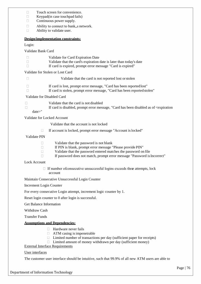
Design/implementation constraints:
Login:
Validate Bank Card
Validate for Card Expiration Date
Validate that the card's expiration date is later than today's date If card is expired, prompt error message "Card is expired"
Validate for Stolen or Lost Card
Validate that the card is not reported lost or stolen
If card is lost, prompt error message, "Card has been reported lost"
If card is stolen, prompt error message, "Card has been reported stolen"
Validate for Disabled Card
Validate that the card is not disabled
If card is disabled, prompt error message, "Card has been disabled as of <expiration date>"
Validate for Locked Account
Validate that the account is not locked
If account is locked, prompt error message "Account is locked"
Validate PIN
Validate that the password is not blank
If PIN is blank, prompt error message "Please provide PIN"
Validate that the password entered matches the password on file
If password does not match, prompt error message "Password is Incorrect"
Lock Account
If number ofconsecutive unsuccessful logins exceeds three attempts, lock
account
Maintain Consecutive Unsuccessful Login Counter
Increment Login Counter
For every consecutive Login attempt, increment logic counter by 1.
Reset login counter to 0 after login is successful.
Get Balance Information
Withdraw Cash
Transfer Funds
Assumptions and Dependencies:
Hardware never fails
ATM casing is impenetrable
Limited number of transactions per day (sufficient paper for receipts)
Limited amount of money withdrawn per day (sufficient money) External Interface Requirements
User interfaces
The customer user interface should be intuitive, such that 99.9% of all new ATM users are able to

Page | 77
Department of Information Technology
complete their banking transactions without any assistance.
Hardware interfaces
The hardware should have following specifications:
Ability to read the ATM card
Ability to count the currency notes
Touch screen for convenience
Keypad (in case touchpad fails)
Continuous power supply
Ability to connect to bank„s network
Ability to take input from user Ability to validate user
Software interfaces
The software interfaces are specific to the target banking software systems. At present, two known
banking systems will participate in the ATM network.
State Bank
Indian Overseas Bank
Safety requirements:
Must be safe kept in physical aspects, say in a cabin
Must be bolted to floor to prevent any kind of theft
Must have an emergency phone outside the cabin
There must be an emergency phone just outside the cabin
The cabin door must have an ATM card swipe slot
The cabin door will always be locked, which will open only when user swipes his/her ATM card in the slot & is validated as genuine
Security requirements:
Users accessibility is censured in all the ways
Users are advised to change their PIN on first use
Users are advised not to tell their PIN to anyone The maximum number of attempts to enter PIN will be three
Some of the possible Bugs on ATM machine?
1. 1.Successful insertion of ATM card
2. Unsuccessful operation due to insert card in wrong angle
3. Unsuccessful operation due to invalid account Ex: other bank card or time expired card
4. successful entry of PIN number
5. un successful operation due to enter wrong PIN number 3times
6. successful selection of language
7. successful selection of account type
8. unsuccessful operation due to invalid account type
9. successful selection of withdraw operation
10. successful selection of amount to be withdrawl
11. successful withdraw operation
Page | 78
Department of Information Technology
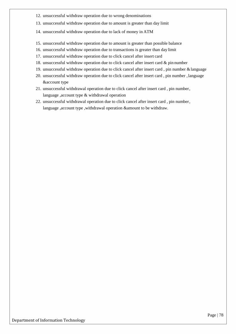
12. unsuccessful withdraw operation due to wrong denominations
13. unsuccessful withdraw operation due to amount is greater than day limit
14. unsuccessful withdraw operation due to lack of money in ATM
15. unsuccessful withdraw operation due to amount is greater than possible balance
16. unsuccessful withdraw operation due to transactions is greater than day limit
17. unsuccessful withdraw operation due to click cancel after insert card
18. unsuccessful withdraw operation due to click cancel after insert card & pin number
19. unsuccessful withdraw operation due to click cancel after insert card , pin number & language
20. unsuccessful withdraw operation due to click cancel after insert card , pin number , language
&account type
21. unsuccessful withdrawal operation due to click cancel after insert card , pin number ,
language ,account type & withdrawal operation
22. unsuccessful withdrawal operation due to click cancel after insert card , pin number ,
language ,account type ,withdrawal operation &amount to be withdraw.

Page | 79
Department of Information Technology
RECORD NOTES

Page | 80
Department of Information Technology
RECORD NOTES

Page | 81
Department of Information Technology
RECORD NOTES

Page | 82
Department of Information Technology
RECORD NOTES

Page | 83
Department of Information Technology
EXPERIMENT: 4
NAME OF THE EXPERIMENT: Test cases for Banking Applications
Banking applications are considered to be one of the most complex applications in today’s software
development and testing industry. What makes Banking application so complex? What approach
should be followed in order to test the complex workflows involved? In this article we will be
highlighting different stages and techniques involved in testing Banking applications. The
characteristics of a Banking application are as follows:
Multi tier functionality to support thousands of concurrent user sessions
Large scale Integration , typically a banking application integrates with numerous other
applications such as Bill Pay utility and Trading accounts
Complex Business workflows
Real Time and Batch processing
High rate of Transactions per seconds
Secure Transactions
Robust Reporting section to keep track of day to day transactions
Strong Auditing to troubleshoot customer issues
Massive storage system
Disaster Management.
The above listed ten points are the most important characteristics of a Banking application.
Banking applications have multiple tiers involved in performing an operation. For Example, a
banking application may have:
1. Web Server to interact with end users via Browser
2. Middle Tier to validate the input and output for web server
3. Data Base to store data and procedures
4. Transaction Processor which could be a large capacity Mainframe or any other Legacy
system to carry out Trillions of transactions per second.
If we talk about testing banking applications it requires an end to end testing methodology involving
multiple software testing techniques to ensure:
Total coverage of all banking workflows and Business Requirements
Functional aspect of the application
Security aspect of the application
Data Integrity
Concurrency
User Experience
Typical stages involved in testing Banking Applications are shown in below workflow which we
will be discussing individually.

Information Technology Page 84
1) Requirement Gathering:
Requirement gathering phase involves documentation of requirements either as Functional
Specifications or Use Cases. Requirements are gathered as per customer needs and documented by
Banking Experts or Business Analyst. To write requirements on more than one subject experts are
involved as banking itself has multiple sub domains and one full fledge banking application will be
the integration of all. For Example: A banking application may have separate modules for Transfers,
Credit Cards, Reports, Loan Accounts, Bill Payments, Trading Etc.
2) Requirement Review:
The deliverable of Requirement Gathering is reviewed by all the stakeholders such as QA Engineers,
Development leads and Peer Business Analysts. They cross check that neither existing business
workflows nor new workflows are violated.
3) Business Scenario Preparations:
In this stage QA Engineers derive Business Scenarios from the requirement documents (Functions
Specs or Use Cases); Business Scenarios are derived in such a way that all Business Requirements are
covered. Business Scenarios are high level scenarios without any detailed steps, further these Business
Scenarios are reviewed by Business Analyst to ensure all of Business Requirements are met and its
easier for BAs to review high level scenarios than reviewing low level detailed Test Cases.
Information Technology Page 85
4) Functional Testing:
In this stage functional testing is performed and the usual software testing activities are performed
such as:
Test Case Preparation:
In this stage Test Cases are derived from Business Scenarios, one Business Scenario leads to several
positive test cases and negative test cases. Generally tools used during this stage are Microsoft Excel,
Test Director or Quality Center.
Test Case Review:
Reviews by peer QA Engineers
Test Case Execution:
Test Case Execution could be either manual or automatic involving tools like QC, QTP or any
other.
5) Database Testing:
Banking Application involves complex transaction which are performed both at UI level and Database
level, Therefore Database testing is as important as functional testing. Database in itself is an entirely
separate layer hence it is carried out by database specialists and it uses techniques like
Data loading
Database Migration
Testing DB Schema and Data types
Rules Testing
Testing Stored Procedures and Functions
Testing Triggers
Data Integrity
6) Security Testing:
Security Testing is usually the last stage in the testing cycle as completing functional and non
functional are entry criteria to commence Security testing. Security testing is one of the major stages in the entire Application testing cycle as this stage ensures that application complies with Federal and Industry standards. Security testing cycle makes sure the application does not have any web vulnerability which may expose sensitive data to an intruder or an attacker and complies with standards like OWASP.
In this stage the major task involves in the whole application scan which is carried out using tools like
IBM Appscan or HP WebInspect (2 Most popular tools).
Once the Scan is complete the Scan Report is published out of which False Positives are filtered out
and rest of the vulnerability are reported to Development team for fixing depending on the Severity.
Other Manual tools for Security Testing used are: Paros Proxy, Http Watch, Burp Suite, Fortify
tools Etc.
Apart from the above stages there might be different stages involved like Integration Testing and
Performance Testing.
In today„s scenario majority of Banking Projects are using: Agile/Scrum, RUP and Continuous
Integration methodologies, and Tools packages like Microsoft„s VSTS and Rational Tools.
As we mentioned RUP above, RUP stands for Rational Unified Process, which is an iterative software
development methodology introduced by IBM which comprises of four phases in which development
and testing activities are carried out.

Information Technology Page 86
Four phases are:
i) Inception ii) Collaboration iii) Construction and
iv) Transition
RUP widely involves IBM Rational tools.
In this article we discussed how complex a Banking application could be and what are the typical
phases involved in testing the application. Apart from that we also discussed current trends followed by IT industries including software development methodologies and tools.
Test cases for opening bank account
1. Input parameters checking -
Name
-Date of Birth -
Photo -Address
Proof -Identity
proof
-Introducers (if applicable) -
PAN card
-Initial deposit
-Whether checkbook / ATM card / Online banking facilities are needed or not -Customer
signature
Type of account -
Savings account -Salary
account -Joint account -
Current account -
Secondary account -RD
account
-Account for a company
Test cases
-Checking mandatory input parameters -Checking
optional input parameters -Check whether able to
create account entity.
-Check whether you are able to deposit an amount in the newly created account (and thus updating the
balance)
-Check whether you are able to withdraw an amount in the newly created account (after deposit) (and
thus updating the balance)
-Check whether company name and its pan number and other details are provided in case of salary
account
-Check whether primary account number is provided in case of secondary account
-Check whether company details are provided in cases of company's current account
-Check whether proofs for joint account is provided in case of joint account
-Check whether you are able deposit an account in the name of either of the person in an joint

Page | 87
account.
-Check whether you are able withdraw an account in the name of either of the person in an joint
account.
-Check whether you are able to maintain zero balance in salary account
-Check whether you are not able to maintain zero balance (or mini balance) in non-salary account.
viva questions
1. Can you explain boundary value analysis?
2. Can you explain equivalence partitioning?
3. Can you explain random/monkey testing?
4. What are semi-random test cases?
5. What is negative and positive testing?
6. How did you define severity ratings in your project?

Page | 88
RECORD NOTES

Page | 89
RECORD NOTES

Page | 90
RECORD NOTES

Page | 91
EXPERIMENT: 5
NAME OF THE EXPERIMENT: Test plan document for Library Management System
The Library Management System is an online application for assisting a librarian in managing a book
library in a University. The system would provide basic set of features to add/update clients,
add/update books, search for books, and manage check-in / checkout processes. Our test group tested
the system based on the requirement specification.
INTRODUCTION
This test report is the result for testing in the LMS. It mainly focuses on two problems: what we will
test and how we will test.
Result
GUI test
Pass criteria: librarians could use this GUI to interface with the backend library database without any difficulties
Result: pass
Database test
Pass criteria: Results of all basic and advanced operations are normal (refer to section 4)
Result: pass
Basic function test
Add a student
Pass criteria:
Each customer/student should have following attributes: Student ID/SSN (unique), Name,
Address and Phone number.
Result: pass
The retrieved customer information by viewing customer detail should contain the four attributes.
Result: pass
Update/delete student
Pass criteria:
The record would be selected using the student ID Result:
pass
Updates can be made on full. Items only: Name, Address, Phone number Result: pass
The record can be deleted if there are no books issued by user.
Result: Partially pass. When no books issued by user, he can be deleted. But when there are
books Issued by this user, he was also deleted. It is wrong.
The updated values would be reflected if the same customer's ID/SSN is called for.
Result: pass
If customer were deleted, it would not appear in further search queries.
Result: pass
Add a book
Pass criteria:
Each book shall have following attributes: Call Number, ISBN, Title, Author name.
Result: pass
The retrieved book information should contain the four attributes.
Result: pass
Update/delete book
Pass criteria:
The book item can be retrieved using the call number Result: did not
pass. Can not retrive using the call number
The data items which can be updated are: ISBN, Title, Author name Result: passThe book can be deleted
Page | 92
only if no user has issued it.
Result: partially pass. When no user has issued it, pass. When there are user having issued it,
did not pass
The updated values would be reflected if the same call number is called for Result: pass
If book were deleted, it would not appear in further search queries. Result: pass
Search for book
Pass criteria:
The product shall let Librarian query books„ detail information by their ISBN number or Author
or Title.
Result: pass
The search results would produce a list of books, which match the search parameters with
following Details: Call number, ISBN number, Title, Author Result: pass
The display would also provide the number of copies which is available for issue Result: pass
The display shall provide a means to select one or more rows to a user-list Result: pass
A detailed view of each book should provide information about check-in/check out status, with
the borrower„s information.
Result: pass
The search display will be restricted to 20 results per page and there would be means to navigate
from sets of search results.
Result: pass
The user can perform multiple searches before finally selecting a set of books for check in or
checkout. These should be stored across searches.
Result: pass
A book may have more than one copy. But every copy with the same ISBN number should have
same detail information.
Result: pass
The borrower„s list should agree with the data in students„ account
Result: pass
Check-in book
Pass criteria:
Librarians can check in a book using its call number
Result: pass
The check-in can be initiated from a previous search operation where user has selected a set of
books.
Result: pass
The return date would automatically reflect the current system date. Result: did not
pass.
Any late fees would be computed as difference between due date and return date at rate of 10
cents a day.
Result: did not pass
A book, which has been checked in once, should not be checked in again Result: pass
Check-out book
Pass criteria:
Librarians can check out a book using its call number Result: pass
The checkout can be initiated from a previous search operation where user has selected a set of
books.
Result: pass
The student ID who is issuing the book would be entered
Result: pass
The issue date would automatically reflect the current system date. Result: did not
pass

Page | 93
The due date would automatically be stamped as 5 days from current date. Result: did not
pass
A book, which has been checked out once, should not be checked out again Result: pass
A student who has books due should not be allowed to check out any books Result: did not
pass
The max. No of books that can be issued to a customer would be 10. The system should not allow
checkout of books beyond this limit.
Result: pass
View book detail
Pass criteria:
This view would display details about a selected book from search operation Result: pass
The details to be displayed are: Call number, IBN, Title, Author, Issue status (In library or
checked out), If book is checked out it would display, User ID & Name, Checkout date, Due date
Result: for checkout date and due date, did not pass
Books checked in should not display user summary
Result: pass
Books checked out should display correct user details. Result:
pass
View student detail
Pass criteria:
Librarians can select a user record for detailed view Result:
pass
The detail view should show:
a.User name, ID, Address & Phone number Result:
pass
b. The books issued by user with issue date, due date, call number, title Result: did not
pass
c. Late fees & Fines summary and total
Result: did not pass
The display should match existing user profile Result:
pass
The books checked out should have their statuses marked Result: pass
The book search query should show the user id correctly. Result: pass
Network test
Pass criteria: Results of operations (ping, ftp and ODBC connectivity check) are normal
Result: did not test this item, because no enough machines and no available envirenment.
Viva questions
1. How to create a test plan document for Library Management System?
2. what is object repository
3. How many test cases can u write 1) File - open dialog box in notepad please
write 5 if software failed in customer environment what we called a)error b)fault c)defect d)failure
4.What test plan should contains?
5. What is test strategy?
6. Define test Plan?What is the difference between Master Test Plan and Test Plan?

Page | 94
RECORD NOTES

Page | 95
RECORD NOTES

Page | 96
RECORD NOTES

Page | 97
EXPERIMENT: 6
NAME OF THE EXPERIMENT: Study of Any Testing Tool( Jmeter)
What is JMeter? Why it is used?
The Apache JMeterTM
is pure Java open source software, which was first developed by Stefano Mazzocchi of
the Apache Software Foundation, designed to load test functional behavior and measure performance. You can use JMeter to
analyze and measure the performance of web application or a variety of services. Performance Testing means testing a web
application against heavy load, multiple and concurrent user traffic. JMeter originally is used for testing Web Application or
FTP application.
Nowadays, it is used for a functional test, database server test etc.
Why JMeter?
Have you ever tested a web server to know how efficiently it works? How many concurrent users can a web server handle?
Let say that one day, your boss asks you to do performance testing of www.google.com for 100 users. What would you do?

Page | 98
It's not feasible to arrange 100 people with PC and internet access simultaneously accessing google.com Think of the
infrastructure requirement when you test for 10000 users (a small number for a site like google). Hence you need a software
tool like JMeter that will simulate real-user behaviors and performance/load test your site.
JMeter Advantages
Open source license: JMeter is totally free, allows developer use the source code for the development
Friendly GUI: JMeter is extremely easy to use and doesn't take time to get familiar with it
Platform independent: JMeter is 100% pure Java desktop application. So it can run on multiple platforms
Full multithreading framework. JMeter allows concurrent and simultaneous sampling of different functions by a
separate thread group
Visualize Test Result: Test result can be displayed in a different format such as chart, table, tree and log file
Easy installation: You just copy and run the *.bat file to run JMeter. No installation needed.
Highly Extensible: You can write your own tests. JMeter also supports visualization plugins allow you to extend
your testing
Multiple testing strategy: JMeter supports many testing strategies such as Load Testing, Distributed Testing,
and Functional Testing.
Simulation: JMeter can simulate multiple users with concurrent threads, create a heavy load against web application
under test
Support multi-protocol: JMeter does not only support web application testing but also evaluate database server
performance. All basic protocols such as HTTP, JDBC, LDAP, SOAP, JMS, and FTP are supported by JMeter
Record & Playback - Record the user activity on the browser and simulate them in a web application using JMeter
Script Test: Jmeter can be integrated with Bean Shell & Selenium for automated testing.
How does JMeter work?
The basic workflow of JMeter as shown in the figures below
JMeter simulates a group of users sending requests to a target server, and return statistics information of target server through
graphical diagrams

Page | 99
The completed workflow of JMeter as shown in the figure below
How to Use JMeter for Performance & Load Testing
Performance Testing is crucial to determine that the web application under test will satisfy high load requirements. It can be
used to analyze overall server performance under heavy load.
Apache JMeter testing tool offers following benefit in Performance Testing

Page | 100
JMeter can be used to test the performance of both static resources such as JavaScript and HTML, as well
as dynamic resources, such as JSP, Servlets, and AJAX.
JMeter can discover maximum number of concurrent users that your website can handle
JMeter provides a variety of graphical analyses of performance reports.
JMeter Performance Testing includes:
Load Testing: Modeling the expected usage by simulating multiple user access the Web services concurrently.
Stress Testing: Every web server has a maximum load capacity. When the load goes beyond the limit, the web server
starts responding slowly and produce errors. The purpose of the Stress Testing is to find the maximum load the web
server can handle.
The figure below shows how JMeter load Testing simulates the heavy load:
Create a Performance Test Plan in JMeter
In this tutorial, we are doing a performance analysis of Google.com for 1000 users
Before testing the performance of target web application, we should determine-
Normal Load: Average number of users visit your website
Heavy Load: The maximum number of users visit your website
What is your target in this test?
Here is the roadmap of this practical example

Page | 101
Step 1) Add Thread Group
1. Start JMeter
2. Select Test Plan on the tree
3. Add Thread Group
Right click on the "Test Plan" and add a new thread group: Add -> Threads (Users) -> Thread Group
In the Thread Group control panel, enter Thread Properties as follows:
Number of Threads: 100 (Number of users connects to the target website: 100)
Loop Count: 10 (Number of time to execute testing)
Ramp-Up Period: 100
The Thread Count and The Loop Counts are different.

Page | 102
Ramp-Up Period tells JMeter how long to delay before starting the next user. For example, if we have 100 users and a 100-
second Ramp-Up period, then the delay between starting users would be 1 second (100 seconds /100 users)
Step 2) Adding JMeter elements
Now we determine what JMeter elements in this test. The elements are
HTTP request Default
This element can be added by right-clicking on the Thread Group and selecting: Add -> Config Element -> HTTP Request
Defaults.
In the HTTP Request Defaults control panel, enter the Website name under test (http://www.google.com)
HTTP Request
Right-click on Thread Group and select: Add -> Sampler -> HTTP Request.
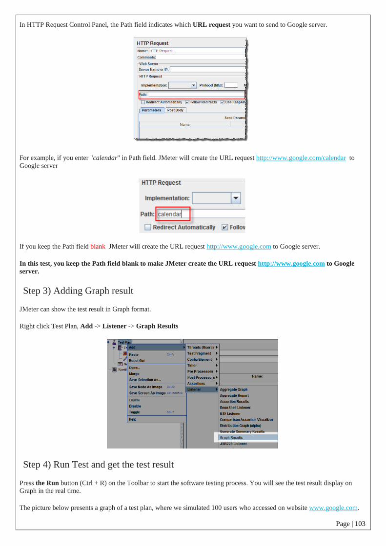
Page | 103
In HTTP Request Control Panel, the Path field indicates which URL request you want to send to Google server.
For example, if you enter "calendar" in Path field. JMeter will create the URL request http://www.google.com/calendar to
Google server
If you keep the Path field blank JMeter will create the URL request http://www.google.com to Google server.
In this test, you keep the Path field blank to make JMeter create the URL request http://www.google.com to Google
server.
Step 3) Adding Graph result
JMeter can show the test result in Graph format.
Right click Test Plan, Add -> Listener -> Graph Results
Step 4) Run Test and get the test result
Press the Run button (Ctrl + R) on the Toolbar to start the software testing process. You will see the test result display on
Graph in the real time.
The picture below presents a graph of a test plan, where we simulated 100 users who accessed on website www.google.com.

Page | 104
At the bottom of the picture, there are the following statistics, represented in colors:
Black: The total number of current samples sent.
Blue: The current average of all samples sent.
Red: The current standard deviation.
Green: Throughput rate that represents the number of requests per minute the server handled
Lets analyze the performance of Google server in below figure.
To analyze the performance of the web server under test, you should focus on 2 parameters
Throughput
Deviation
The Throughput is the most important parameter. It represents the ability of the server to handle a heavy load.
The higher the Throughput is, the better is the server performance.

Page | 105
In this test, the throughput of Google server is 1,491.193/minute. It means Google server can handle 1,491.193 requests per
minute. This value is quite high so we can conclude that Google server has good performance
The deviation is shown in red - it indicates the deviation from the average. The smaller the better.
Let compare the performance of Google server to other web servers. This is the performance test result of
website http://www.yahoo.com/ (You can choose other websites)
The throughput of a website under test http://www.yahoo.com is 867.326/minutes. It means this server handle 867.326
requests per minute, lower than Google.
The deviation is 2689, much higher than Google (577). So we can determine the performance of this website is less than a
Google server.
NOTE: The above values depend on several factors like current server load at Google, your internet speed, your CPU power
etc. Hence, it's very unlikely that you will get the same results as above.
Troubleshooting:
If you face the issue while running the above scenario ... do the following
1. Check whether you are connecting to the internet via a proxy. If yes, remove the proxy.
2. Open a new instance of Jmeter
3. Open the PerformanceTestPlan.jmx in Jmeter
4. Double Click on Thread Group -> Graph Result
5. Run the Test

Page | 106
RECORD NOTES

Page | 107
RECORD NOTES

Page | 108
RECORD NOTES

Page | 109
RECORD NOTES

Page | 110
EXPERIMENT: 7
NAME OF THE EXPERIMENT: Study of any web testing tool (e.g. Selenium)
What is Selenium?
JavaScript framework that runs in your web browser Works anywhere JavaScript is supported
Hooks for many other languages Java, Ruby, Python Can simulate a user navigating through pages
and then assert for specific marks on the pages All you need to really know is HTML to start using it
right away
Selenium IDE
Selenium Integrated Development Environment (IDE) is a Firefox plugin that lets testers to record
their actions as they follow the workflow that they need to test.
It provides a Graphical User Interface for recording user actions using Firefox which is used to learn
and use Selenium, but it can only be used with Firefox browser as other browsers are not supported.
However, the recorded scripts can be converted into various programming languages supported by
Selenium and the scripts can be executed on other browsers as well.
Selenium- IDEDownload
Step 1 − Launch Firefox and navigate to the following URL - http://seleniumhq.org/download/.
Under the Selenium IDE section, click on the link that shows the current version number as shown
below.
Step 2 − Firefox add-ons notifier pops up with allow and disallow options. User has to allow the
installation.

Page | 111
Step 3 − The add-ons installer warns the user about untrusted add-ons. Click 'Install Now'.
Step 4 − The Selenium IDE can now be accessed by navigating to Tools >>Selenium IDE.
Step 5 − The Selenium IDE can also be accessed directly from the quick access menu bar as shown
below.
Selenium IDE Features
This section deals with the features available in Selenium IDE.
The following image shows the features of Selenium IDE with the help of a simple tool-tip.
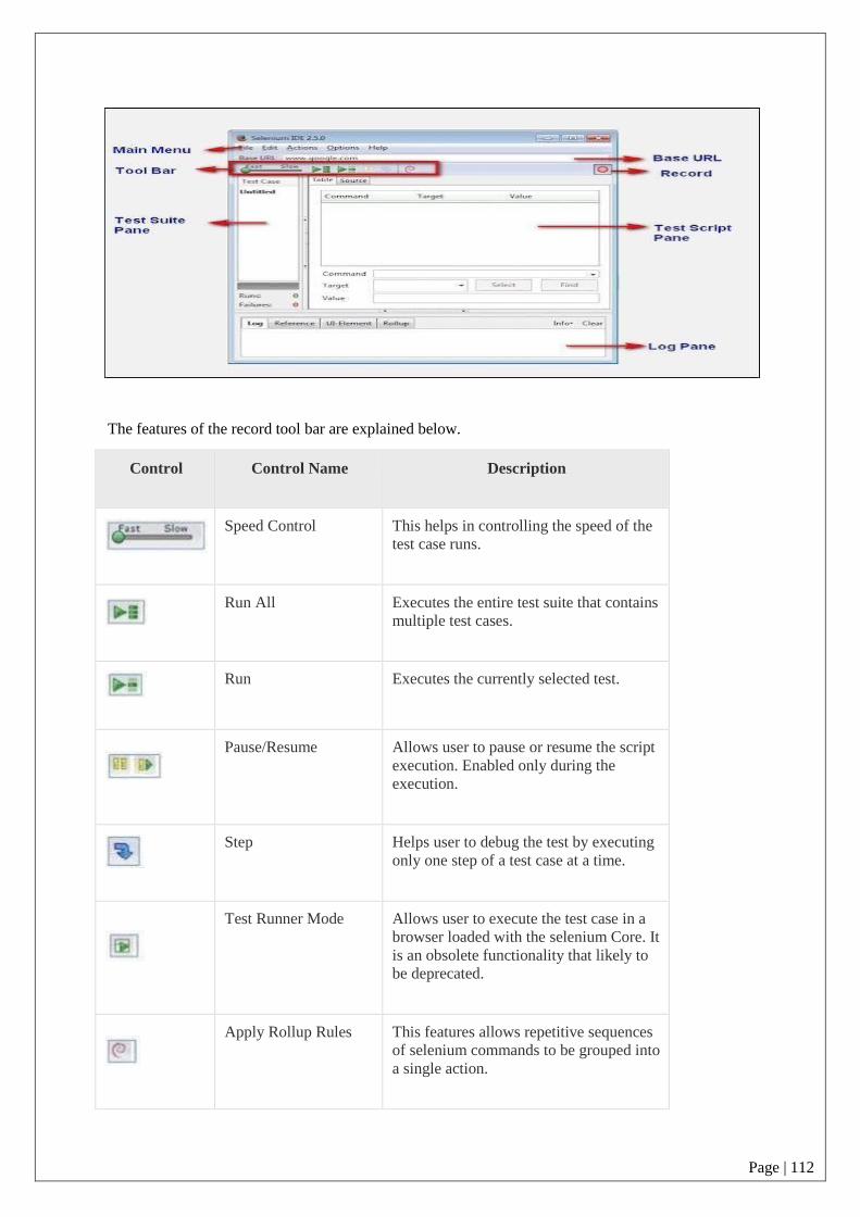
Page | 112
The features of the record tool bar are explained below.
Control Control Name Description
Speed Control This helps in controlling the speed of the
test case runs.
Run All Executes the entire test suite that contains
multiple test cases.
Run Executes the currently selected test.
Pause/Resume Allows user to pause or resume the script
execution. Enabled only during the
execution.
Step Helps user to debug the test by executing
only one step of a test case at a time.
Test Runner Mode Allows user to execute the test case in a
browser loaded with the selenium Core. It
is an obsolete functionality that likely to
be deprecated.
Apply Rollup Rules This features allows repetitive sequences
of selenium commands to be grouped into
a single action.

Page | 113
Record This features helps user to Records the
user's browser actions.
Creating Selenium IDE Tests
This section deals with how to create IDE tests using recording feature.
The following steps are involved in creating Selenium tests using IDE −
Recording and adding commands in a test
Saving the recorded test
Saving the test suite
Executing the recorded test
Recordingand Adding CommandsinaTest
We will use www.ncalculators.com to demonstrate the features of Selenium.
Step 1 − Launch the Firefox browser and navigate to the website - https://www.ncalculators.com/
Step 2 − Open Selenium IDE from the Tools menu and press the record button that is on the top-
right corner.
Step 3 − Navigate to "Math Calculator" >> "Percent Calculator >> enter "10" as number1 and 50 as
number2 and click "calculate".

Page | 114
Step 4 − User can then insert a checkpoint by right clicking on the webelement and select "Show all
available commands" >> select "assert text css=b 5"
Step 5 − The recorded script is generated and the script is displayed as shown below.
Savingthe Recorded Test
Step 1 − Save the Test Case by navigating to "File" >> "Save Test" and save the file in the location
of your choice. The file is saved as .HTML as default.
The test can also be saved with an extension htm, shtml, and xhtml.

Page | 115
Savingthe Test Suite
A test suite is a collection of tests that can be executed as a single entity.
Step 1 − Create a test suite by navigating to "File" >> "New Test Suite" as shown below.
Step 2 − The tests can be recorded one by one by choosing the option "New Test Case" from the
"File" Menu.

Page | 116
Step 3 − The individual tests are saved with a name along with saving a "Test
Suite".
Executingthe Recorded Test
The recorded scripts can then be executed either by clicking "Play entire suite" or "Play current test"
button in the toolbar.
Step 1 − The Run status can be seen in the status pane that displays the number of tests passed and
failed.
Step 2 − Once a step is executed, the user can see the result in the "Log" Pane.
Step 3 − After executing each step, the background of the test step turns "Green" if passed and "Red"
if failed as shown below.
Selenium IDE Script Debugging
This section deals with debugging the Selenium IDE script.
Debugging is the process of finding and fixing errors in the test script. It is a common step in any
script development. To make the process more robust, we can make use a plugin "Power Debugger"
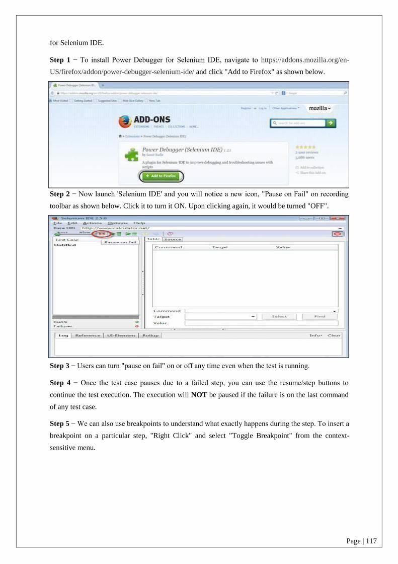
Page | 117
for Selenium IDE.
Step 1 − To install Power Debugger for Selenium IDE, navigate to https://addons.mozilla.org/en-
US/firefox/addon/power-debugger-selenium-ide/ and click "Add to Firefox" as shown below.
Step 2 − Now launch 'Selenium IDE' and you will notice a new icon, "Pause on Fail" on recording
toolbar as shown below. Click it to turn it ON. Upon clicking again, it would be turned "OFF".
Step 3 − Users can turn "pause on fail" on or off any time even when the test is running.
Step 4 − Once the test case pauses due to a failed step, you can use the resume/step buttons to
continue the test execution. The execution will NOT be paused if the failure is on the last command
of any test case.
Step 5 − We can also use breakpoints to understand what exactly happens during the step. To insert a
breakpoint on a particular step, "Right Click" and select "Toggle Breakpoint" from the context-
sensitive menu.

Page | 118
Step 6 − Upon inserting the breakpoint, the particular step is displayed with a pause icon as shown
below.
Step 7 − When we execute the script, the script execution is paused where the breakpoint is inserted.
This will help the user to evaluate the value/presence of an element when the execution is in
progress.

Page | 119
Inserting Verification Points
This section describes how to insert verification points in Selenium IDE.
The test cases that we develop also need to check the properties of a web page. It requires assert and
verify commands. There are two ways to insert verification points into the script.
To insert a verification point in recording mode, "Right click" on the element and choose "Show all
Available Commands" as shown below.
We can also insert a command by performing a "Right-Click" and choosing "Insert New Command".

Page | 120
After inserting a new command, click 'Command' dropdown and select appropriate verification point
from the available list of commands as shown below.
Given below are the mostly used verification commands that help us check if a particular step has
passed or failed.
verifyElementPresent
assertElementPresent
verifyElementNotPresent
assertElementNotPresent
verifyText
assertText
verifyAttribute
assertAttribute
verifyChecked
assertChecked

Page | 121
verifyAlert
assertAlert
verifyTitle
assertTitle
SynchronizationPoints
During script execution, the application might respond based on server load, hence it is required for
the application and script to be in sync. Given below are few a commands that we can use to ensure
that the script and application are in sync.
waitForAlertNotPresent
waitForAlertPresent
waitForElementPresent
waitForElementNotPresent
waitForTextPresent
waitForTextNotPresent
waitForPageToLoad
waitForFrameToLoad
Selenium Pattern Matching
This section deals with how to work with regular expressions using IDE.
Like locators, patterns are a type of parameter frequently used by Selenium. It allows users to
describe patterns with the help of special characters. Many a time, the text that we would like to
verify are dynamic; in that case, pattern matching is very useful.
Pattern matching is used with all the verification point commands - verifyTextPresent, verifyTitle,
verifyAlert, assertConfirmation, verifyText, and verifyPrompt.
There are three ways to define a pattern −
globbing
regular expressions, and
exact patterns.
Globbing
Most techies who have used file matching patterns in Linux or Windows while searching for a
certain file type like *.doc or *.jpg. would be familiar with term "globbing"
Globbing in Selenium supports only three special characters: *, ?, and [ ].
* − matches any number of characters.
? − matches a single character.

Page | 122
[ ] − called a character class, lets you match any single character found within the brackets.
[0-9] matches any digit.
To specify a glob in a Selenium command, prefix the pattern with the keyword 'glob:'. For example,
if you would like to search for the texts "tax year 2013" or "tax year 2014", then you can use the golb
"tax year *" as shown below.
However the usage of "glob:" is optional while specifying a text pattern because globbing patterns
are the default in Selenium.
Command Target Value
clickAndWait link = search
verifyTextPresent glob: tax year *
Exact Patterns
Patterns with the prefix 'exact:' will match the given text as it is. Let us say, the user wants an exact
match with the value string, i.e., without the glob operator doing its work, one can use the 'exact'
pattern as shown below. In this example the operator '*' will work as a normal character rather than a
pattern-matching wildcard character.
Command Target Value
clickAndWait link = search
verifyValue exact: *.doc
Regular Expressions
Regular expressions are the most useful among the pattern matching techniques available. Selenium
supports the complete set of regular expression patterns that Javascript supports. Hence the users are
no longer limited by *, ? and [] globbing patterns.
To use RegEx patterns, we need to prefix with either "regexp:" or "regexpi:". The prefix "regexpi" is
case-insensitive. The glob: and the exact: patterns are the subsets of the Regular Expression patterns.
Everything that is done with glob: or exact: can be accomplished with the help of RegExp.
Example
For example, the following will test if an input field with the id 'name' contains the string 'tax year',
'Tax Year', or 'tax Year'.
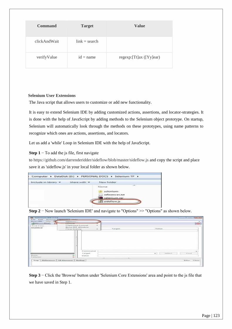
Page | 123
Command Target Value
clickAndWait link = search
verifyValue id = name regexp:[Tt]ax ([Yy]ear)
Selenium User Extensions
The Java script that allows users to customize or add new functionality.
It is easy to extend Selenium IDE by adding customized actions, assertions, and locator-strategies. It
is done with the help of JavaScript by adding methods to the Selenium object prototype. On startup,
Selenium will automatically look through the methods on these prototypes, using name patterns to
recognize which ones are actions, assertions, and locators.
Let us add a 'while' Loop in Selenium IDE with the help of JavaScript.
Step 1 − To add the js file, first navigate
to https://github.com/darrenderidder/sideflow/blob/master/sideflow.js and copy the script and place
save it as 'sideflow.js' in your local folder as shown below.
Step 2 − Now launch 'Selenium IDE' and navigate to "Options" >> "Options" as shown below.
Step 3 − Click the 'Browse' button under 'Selenium Core Extensions' area and point to the js file that
we have saved in Step 1.

Page | 124
Step 4 − Restart Selenium IDE.
Step 5 − Now you will have access to a few more commands such as "Label", "While" etc.
Step 6 − Now we will be able to create a While loop within Selenium IDE and it will execute as
shown below.
Viva questions:
1. What is Selenium?
2. What are the different Selenium components?
3. What are the testing types that can be supported by Selenium?
4. What are the limitations of Selenium? 5. What is Selenese?

Page | 125
RECORD NOTES

Page | 126
RECORD NOTES

Page | 127
RECORD NOTES

Page | 128
EXPERIMENT: 8
NAME OF THE EXPERIMENT: Write a test cases for a) Gmail application b) Face book
Manually .

Page | 129
RECORD NOTES

Page | 130
RECORD NOTES

Page | 131
RECORD NOTES

RECORD NOTES