Embed Size (px)
Citation preview

ERL: Energy Recovery Linacs
Chaivat TengsirivattanaCASA, Jefferson LabUniversity of Virginia
USPAS 2008: RF SuperconductivityAnnapolis, MDJune 27,2008

High-Current Energy-Recovering Electron Linacs
1. Introduction
2. Historical Development of Energy-Recovering Linacs
3. The Jefferson Laboratory Infrared Demonstration Free-Electron Laser
4. Overview of Energy-Recovering Linac Projects and Proposals
5. Scaling of Energy-Recovering Linacs to Higher Energies
6. Scaling of Energy-Recovering Linacs to Higher Currents

Figure 1 Main accelerator types.
1.1 Traditional Types of Electron Accelerators

1.2 Beam Recirculation
MultipassesAccelerate - Decelerate
Linacs1. Electron resides briefly.
2. Laser-driven photocathode – Polarization and control
3. Emittance
4. Pulse duration
Ring1. Equilibrium – by radiation damping
2. Naturally bunched

1.3 Beam Energy RecoverySimplest case: single recirculation
1. Accelerate in 1st pass
2. Recirculate in 2nd pass, plus ½ Rf wavelengths.
Efficiency: Rf to beam multiplication factor
,
b fbeam
RF b inj rf linac
I EPP I E P
κ =+
Accelerating gradients 20 MV/m
Quality factor 1010
Continuous wave

2. Radiofrequency Superconductivity and Recirculating Linacs
Superconducting cavities:
1. CW or high-duty-factor
2. Highly efficient coupling
3. High-average-current
4. Reduction in length of the accelerator
3. Jefferson Laboratory Infrared Demonstration Free-Electron Laser
SRF CEBAF
• High-repetition-rate cw electron beam.
• High-brightness DC electron sources

Figure 2 The Jefferson Laboratory Infrared Demonstration Free-Electron Laser.
3.1 JLab IR Demo FEL System Design
10 MeV to 35-48 MeV

Table 1 System parameters of the JLab IR Demo FEL

Figure 3 Longitudinal matching scenario in the JLab IR Demo FEL, showing phase versus energy diagrams at critical locations.

Figure 4 Beam viewer image in chicane downstream of FEL (dispersion of 0.4 m). Left: lasing, right: no lasing.
3.2 Longitudinal Matching• 2-MeV full energy spread, 20% of 10 MeV.• Energy recovery proved quite efficient.

Figure 5 RF system generator power for each linac cavity without beam, without and with energy recovery at various current levels.

Table 2 Chronology of the JLab IR Demo FEL
3.3 System Operation and Performance

3.4 10kW IR/1kw UV Upgrade1. Doubling current, from 5 to 10 mA, bunch charge from 60 to
135 pC.
2. Installing 2 additional cryomodules, E - 160 MeV.
3. Upgrading the recirculators.
4. Adding a pair of optical cavities.
October 30th, 2006:
14.2kW at 9.1 mA and 150 MeV
160 MeV, 9.1 mA, 150 pC, 74.85 MHz, 7 mm-mrad, 150 fs
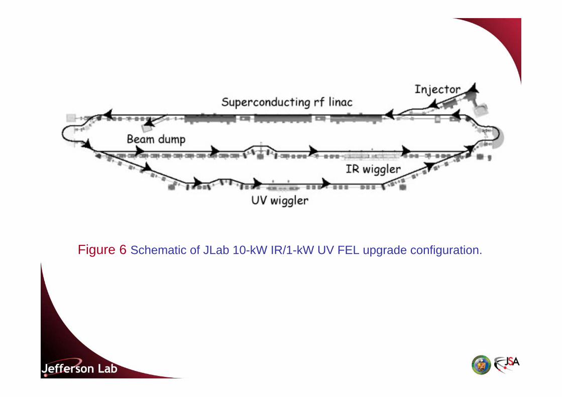
Figure 6 Schematic of JLab 10-kW IR/1-kW UV FEL upgrade configuration.

Table 3 System parameters of the JLab IR and UV FEL upgrade
4.1 High-Average-Power FELs• JAERI FEL, Japan
• Accelerator-Recuperator FEL, Novosibirsk, Russia
• KAERI FEL, Korea
• JLab 10-kW IR FEL Upgrade

4.2 ERL-Based Light SourcesERLs:
• Average current-carrying capability of storage-ring.
• Smaller beam emittance and energy spread.
• Higher photon brilliance and coherence, round sources, and short-pulse-length radiation. 100-fsec pulse width domain.
• ERL at Cornell, 77pC, 1.3 GHz, 100 mA.
• PERL at Brookhaven.
• 4GLSP at Daresbury, UK.
• LUX at LBNL.

Figure 7 Accelerator-recuperator FEL in Novosibirsk. 1: electron gun; 2: bending magnets; 3: RF resonators; 4,5: injection and extraction magnets; 6: focusing quadrupoles; 7: straight sections with the quadrupole lenses; 8:
FEL magnetic system; 9: beam dump.

4.3 Beam Electron Cooling• Same gamma, act as heat sink – higher luminosity.
RHIC cooler – 50 MeV, 100 mA ERL.
• High-average-current source, but low frequency = 9 MHz, so high bunch charge = 10 nC.
• Maximize the longitudinal overlap to maximize the cooling rate, beam need to be debunched and rebunched.

4.4 Electron-Ion Colliders• Advantageous and produce higher luminosity.
• Ring: one damping time – 1,000 revolutions.
• Increase Ni
• eRHIC, ELIC
1. Cornell/JLab ERL phase I – 100 MeV, 100 mA.
2. Brookhaven e-cooling prototype.
3. JLab 10-kW FEL Upgrade.
4. CEBAF-ER.
( ) ( )1 2 1 22 2 2 22
e i
ex ix ey iy
fN NLπ σ σ σ σ
=+ +

Figure 8 Energy-recovering linacs in terms of energy versus average current: existing, planned, and proposed ERL-based schemes.
5.1 Injection Energy• Low Ei vs high Ei.
5.2 Number of Passes• Cost-control measure and optimizing performance.
5.3 General Features of Machine Topology• Use of spreaders and recombiners
5.4 Phase-Space Matching• Longitudinal phase-space
• Transverse phase-space
• Graded-gradient focusing

Figure 9 A split-linac topology for ERL-based light source.

Figure 10 Beam envelopes (m) in a 10-MeV to 10-GeV recirculating, energy-recovering accelerator using graded-gradient focusing.

5.5 Phase-Space Preservation• Transfer matrix element
• One parameter, one knob
5.6 Beam Halo• Beam loss 0.1 µA out of 5 mA – kilowatts of lost beam power
5.7 CEBAF-ER Experiment• Chicane – a half-rf-wavelength phase delay.
1. Allow investigation of beam-quality preservation.
2. Allow investigation of dynamic range (injected to full energy ratio).
3. Large-scale demonstration.
• 1 GeV full energy and recovered it, 56 MeV injection Energy, cw and 80 µA.

Figure 11 CEBAF-ER experiment. Accelerated (left) and recovered (right) beams at midpoint of the south linac. This viewer image demonstrates that the decelerating beam remained well-defined and of similar quality to the
accelerating beam.

Figure 12 CEBAF-ER experiment. RF system gradient modulator drive signals during pulsed beam operation, with and without energy
recovery.

6.1 Generation and Preservation of Low-Emittance, High-Current Beams
• Low emittance – 1 mm-mrad.
• Short bunch-length – 1 psec.
• Preservation in low energy regime – space charge effect.
• Linac and beam lines – wakefield effects.
• Recirculators – Coherent Synchrotron Radiation.

6.2 Multibunch Instabilities• ERLs more susceptible, support current approaching or
exceeding these threshold.
• Beam Breakups, HOMs
( ) ( )2
sin 2r
thm m ij m rm
p cIe R Q Q k M t l eω π
−=
+
Longitudinal BBU
• i, j = 5, 6 and m – longitudinal HOM.
Transverse BBU
• i, j = 1, 2 or 3, 4 and m – transverse HOM.
Beam-loading instabilities
i, j = 5, 6 and m – fundamental accelerating.

Figure 13 Beam breakup stability plot for the JLab IR Demo FEL,
By MATBBU codes.

Figure 14 RF cavity response to beam excitation at higher-order mode frequency of 1887 MHz at various beam currents from 0 to 4 mA.

6.3 Superconducting RF Issues and HOM Power Dissipation
• cw beam – high average current.
• Multi GeV.
• Gradient – 20 MV/m
• Q0 – 1 x 10¹⁰
• Extraction of HOMs
• Could be up to 1 kW per cavity, destroy cooper pairs

Figure 15 Measured higher-order mode (HOM) power dissipated in one of two HOM loads per linac cavity versus bunch charge at three
bunch repetition rates.

6.4 RF Coupling Optimization and RF Control• Multiplication factor increases as a function of the loaded
quality factor QL.
• Microphonic vibrations.
• Radiation pressure during turn-on.
• Self-excited loop, Generator-driven system, or Hybrid.
• Piezo to suppress microphonic noise and Lorentz-force-detuning.