Embed Size (px)
Citation preview

CAS Zeuthen
Superconducting Electron Linacs
Nick Walker
DESY
CAS • Zeuthen • 15-16 Sept. 2003
CAS Zeuthen
What’s in Store
• Brief history of superconducting RF• Choice of frequency (SCRF for pedestrians)• RF Cavity Basics (efficiency issues)• Wakefields and Beam Dynamics• Emittance preservation in electron linacs
• Will generally consider only high-power high-gradient linacs– sc e+e- linear collider
– sc X-Ray FELTESLA technology

CAS Zeuthen
MV1659699231040075
L Lilje
Status 1992: Before start of TESLA R&D(and 30 years after the start)

CAS Zeuthen courtesy Hasan Padamsee, Cornell
S.C. RF ‘Livingston Plot’

CAS Zeuthen
TESLA R&D
20039 cell EP cavities

CAS Zeuthen
TESLA R&D

CAS Zeuthen
Ez
z
The Linear Accelerator (LINAC)
c
2ct
standing wave cavity:
bunch sees field:Ez =E0 sin(t+)sin(kz)
=E0 sin(kz+)sin(kz)
c
For electrons, life is easy since• We will only consider relativistic electrons (v c)
we assume they have accelerated from the source by somebody else!• Thus there is no longitudinal dynamics (e± do not move
long. relative to the other electrons)• No space charge effects

CAS Zeuthen
SC RF
Unlike the DC case (superconducting magnets), the surface resistance of a superconducting RF cavity is not zero:
2
exp 1.76 /BCS c
fR T T
T
Two important parameters:• residual resistivity• thermal conductivity
CAS Zeuthen
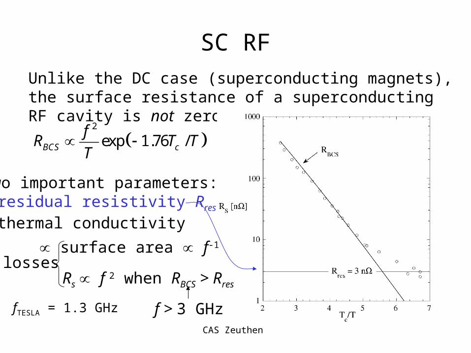
SC RF
Unlike the DC case (superconducting magnets), the surface resistance of a superconducting RF cavity is not zero:
2
exp 1.76 /BCS c
fR T T
T
Two important parameters:• residual resistivity Rres
• thermal conductivity
losses surface area f-1
Rs f 2 when RBCS > Rres
f > 3 GHzfTESLA = 1.3 GHz

CAS Zeuthen
SC RF
Unlike the DC case (superconducting magnets), the surface resistance of a superconducting RF cavity is not zero:
2
exp 1.76 /BCS c
fR T T
T
Two important parameters:• residual resistivity• thermal conductivity
Higher the better!
RRR = Residual Resistivity Ratio
LiHe
Nb
I
heat flow
skin depth 2 /

CAS Zeuthen
RF Cavity BasicsFigures of Merit
• RF power Pcav
• Shunt impedance rs
• Quality factor Q0:
• R-over-Q
z RF sE P R
2cav s cavV r P
00
2
00
stored energy2
energy lost per cycle
/2
cav
cav
cavs
cav
UQ
P
Vr Q
U
rs/Q0 is a constant for a given cavity geometryindependent of surface resistance

CAS Zeuthen
Frequency Scaling
1/ 2
1s
fr
f
1/ 2
0 2
fQ
f
0
sfr
fQ
normal
superconducting
normal
superconducting
normal
superconducting

CAS Zeuthen
RF Cavity BasicsFill Time
0
0
0
0
00
0
0
2
( ) (0)
( ) (0)
cav
cav
cavcav
cavcav
tQ
cav cav
tQ
cav cav
UQ
P
dUP
dtdU
Udt Q
U t U e
V t V e
From definition of Q0
Allow ‘ringing’ cavity to decay(stored energy dissipated in walls)
Combining gives eq. for Ucav
Assuming exponential solution(and that Q0 and 0 are constant)
Since 2cav cavU V
CAS Zeuthen
RF Cavity BasicsFill Time
0
0
2Q
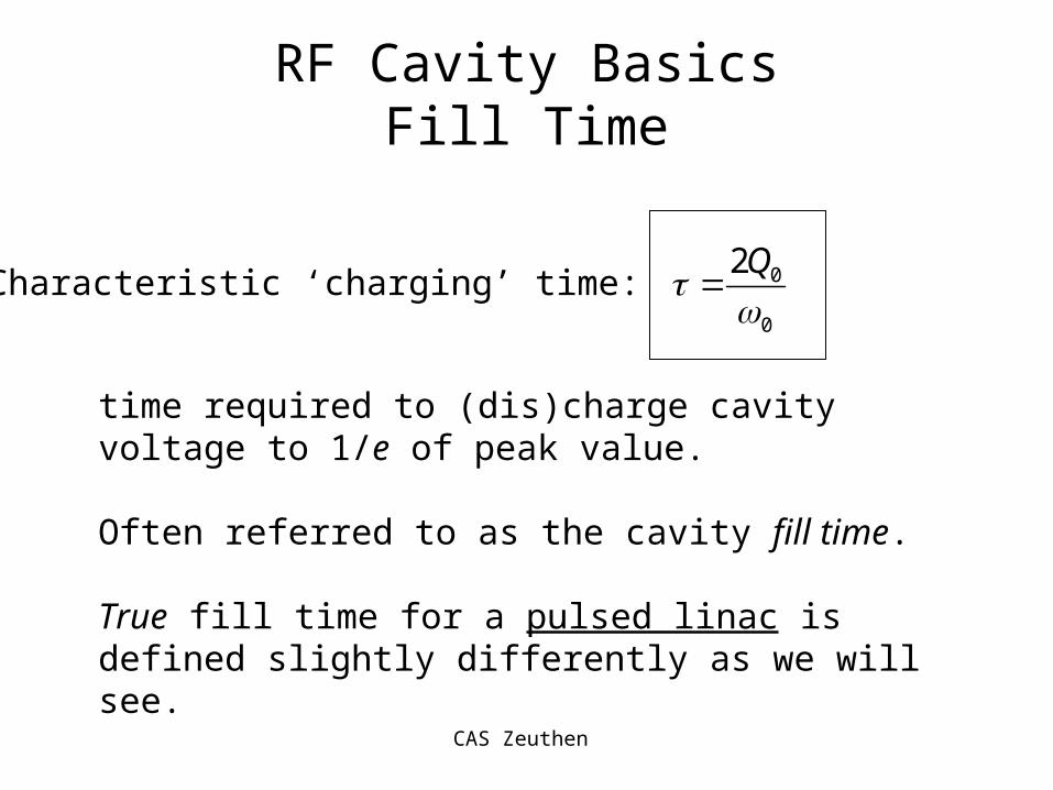
Characteristic ‘charging’ time:
time required to (dis)charge cavity voltage to 1/e of peak value.
Often referred to as the cavity fill time.
True fill time for a pulsed linac is defined slightly differently as we will see.

CAS Zeuthen
RF Cavity BasicsSome Numbers
fRF = 1.3 GHz S.C. Nb (2K) Cu
Q0 5109 2104
R/Q 1 k
R0 51012 2107
Pcav (5 MV) cw! 5 W 1.25 MW
Pcav (25 MV) cw! 125 W 31 MW
fill 1.2 s 5 s

CAS Zeuthen
RF Cavity BasicsSome Numbers
fRF = 1.3 GHz S.C. Nb (2K) Cu
Q0 5109 2104
R/Q 1 k
R0 51012 2107
Pcav (5 MV) cw! 5 W 1.25 MW
Pcav (25 MV) cw! 125 W 31 MW
fill 1.2 s 5 s
Very high Q0: the great
advantage of s.c. RF
Very high Q0: the great
advantage of s.c. RF

CAS Zeuthen
RF Cavity BasicsSome Numbers
fRF = 1.3 GHz S.C. Nb (2K) Cu
Q0 5109 2104
R/Q 1 k
R0 51012 2107
Pcav (5 MV) cw! 5 W 1.25 MW
Pcav (25 MV) cw! 125 W 31 MW
fill 1.2 s 5 s
• very small power loss in cavity walls• all supplied power goes into accelerating the
beam• very high RF-to-beam transfer efficiency• for AC power, must include cooling power
• very small power loss in cavity walls• all supplied power goes into accelerating the
beam• very high RF-to-beam transfer efficiency• for AC power, must include cooling power
CAS Zeuthen
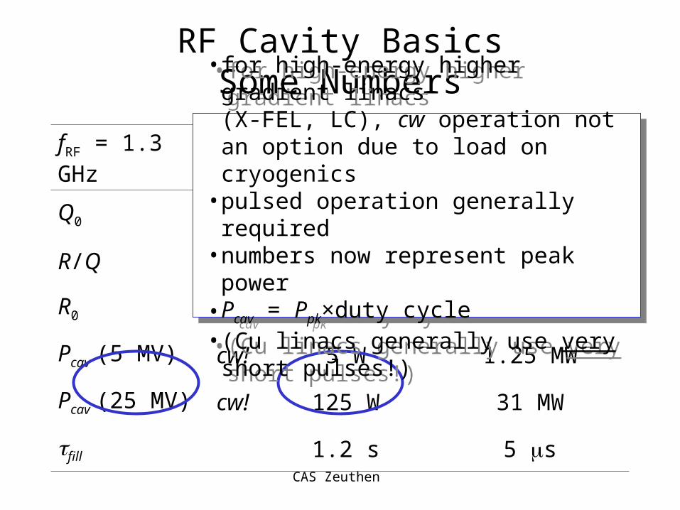
RF Cavity BasicsSome Numbers
fRF = 1.3 GHz S.C. Nb (2K) Cu
Q0 5109 2104
R/Q 1 k
R0 51012 2107
Pcav (5 MV) cw! 5 W 1.25 MW
Pcav (25 MV) cw! 125 W 31 MW
fill 1.2 s 5 s
• for high-energy higher gradient linacs(X-FEL, LC), cw operation not an option due to load on cryogenics
• pulsed operation generally required• numbers now represent peak power• Pcav = Ppk×duty cycle• (Cu linacs generally use very short pulses!)
• for high-energy higher gradient linacs(X-FEL, LC), cw operation not an option due to load on cryogenics
• pulsed operation generally required• numbers now represent peak power• Pcav = Ppk×duty cycle• (Cu linacs generally use very short pulses!)

CAS Zeuthen
Cryogenic Power Requirements
Basic Thermodynamics: Carnot Efficiency (Tcav = 2.2K)
2.20.7%
300 2.2cav
croom cav
T
T T
System efficiency typically 0.2-0.3 (latter for large systems)
Thus total cooling efficiency is 0.14-0.2%
5W / 0.002 2.5kWcoolingP
Note: this represents dynamic load, and depends on Q0 and VStatic load must also be included (i.e. load at V = 0).

CAS Zeuthen
RF Cavity BasicsPower Coupling
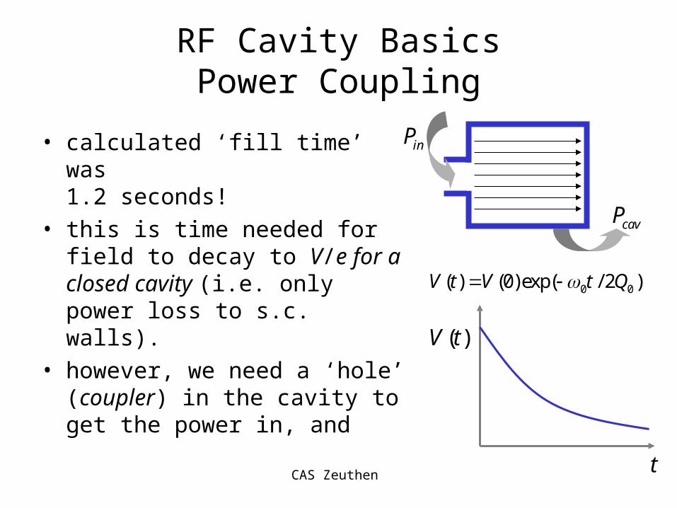
• calculated ‘fill time’ was1.2 seconds!
• this is time needed for field to decay to V/e for a closed cavity (i.e. only power loss to s.c. walls).
0 0( ) (0)exp( / 2 )V t V t Q
cavP
( )V t
t
CAS Zeuthen
RF Cavity BasicsPower Coupling
• calculated ‘fill time’ was1.2 seconds!
• this is time needed for field to decay to V/e for a closed cavity (i.e. only power loss to s.c. walls).
• however, we need a ‘hole’ (coupler) in the cavity to get the power in, and
cavP
inP
0 0( ) (0)exp( / 2 )V t V t Q
( )V t
t

CAS Zeuthen
RF Cavity BasicsPower Coupling
• calculated ‘fill time’ was1.2 seconds!
• this is time needed for field to decay to V/e for a closed cavity (i.e. only power loss to s.c. walls).
• however, we need a ‘hole’ (coupler) in the cavity to get the power in, and
• this hole allows the energy in the cavity to leak out!
cavP
0( ) (0)exp( / 2 )LV t V t Q
outP
( )V t
t

CAS Zeuthen
RF Cavity Basics
Generator(Klystron)
0Z 0Z
0Zmatched load
cavitycouplercirculator
Z0 = characteristic impedance of transmission line (waveguide)

CAS Zeuthen
RF Cavity Basics
Generator(Klystron)
0Z
forP
refP
Klystron power Pfor sees matched impedance Z0
Reflected power Pref from coupler/cavity is dumped in load
Conservation of energy: for ref cavP P P
impedance mismatch

CAS Zeuthen
Equivalent Circuit
Generator(Klystron) 0Z
0Z 0Z
L CR
cavity
1: n
coupler
0Z

CAS Zeuthen
Equivalent Circuit
R
1: n
0Z
Only consider on resonance: 0
1
LC
cavV
0:C
note Q RL

CAS Zeuthen
Equivalent Circuit
R
1: n
20extZ n Z
Only consider on resonance: 0
1
LC
cavV
We can transform the matched load impedance Z0 into the cavity circuit.
2/cavV n/R
CAS Zeuthen
Equivalent Circuit
/ 2sR r
1: n
20extZ n Z cavV2/cavV n
/R
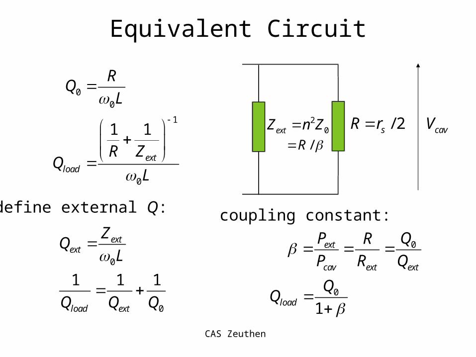
00
1
0
1 1
extload
RQ
L
R ZQ
L
0
0
1 1 1
extext
load ext
ZQ
L
Q Q Q
0ext
cav ext ext
P QR
P R Q
coupling constant:define external Q:
0
1load

CAS Zeuthen
Reflected and TransmittedRF Power
2
2
2
1
1
1
11
1
4
1
ext
ext
cav for ref
for
for
cav for
R Z
R Z
P P P
P
P
P P
2
2 1
1ref for forP P P
reflection coefficient(seen from generator):
from energy conservation:

CAS Zeuthen
Transient Behaviour
steady state cavity voltage:1/ 2
ˆ
2
1
cav cav s
for s
V P r
P r
2ˆ 11cav for ref for for
nV n V V n V V
steady-state result!
think in terms of (travelling) microwaves:
02for forV P Z
ref forV V cav for refV n V V
remember: 0
2
4
(1 )cav forP P
from before:
1
1

CAS Zeuthen
Reflected Transient Power
0
0
ˆ( ) 1 exp / 2
21 exp / 2
1
cav L cav
L for
V t t Q V
nt Q V
0
( )( )
( ) 21 exp / 2 1
1
( )
cavref for
refL
for
V tV t V
nV t
t QV
t
time-dependent reflection coefficient

CAS Zeuthen
Reflected Transient Power
2
0
( ) 21 exp / 2 1
1ref
Lfor
P tt Q
P
after RF turned off 00 2 /for off LV t Q
0
0
ˆexp / 2
2exp / 2
1
cavref L
for L
VV t Q
n
V t Q
2
02
4exp /
1
refL
for
Pt Q
P
offt t t
CAS Zeuthen
RF On
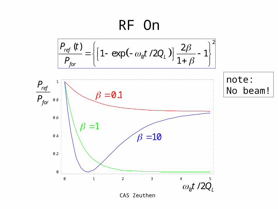
2
0
( ) 21 exp / 2 1
1ref
Lfor
P tt Q
P
0 1 2 3 4 5
0
0.2
0.4
0.6
0.8
1
ref
for
P
P
0 / 2 Lt Q
10
0.1
1
note:No beam!

CAS Zeuthen
Reflected Power in Pulsed Operation
0 2 4 6 8 100
0.5
1
1.5
2
0 2 4 6 8 100
0.5
1
1.5
2
0 2 4 6 8 100
0.5
1
1.5
2
ref
for
P
P
0 / 2 Lt Q
0.5 1 2
Example of square RF pulse with 0 012 /t Q
critically coupled under coupled over coupled

CAS Zeuthen
Accelerating Electrons
• Assume bunches are very short
• model ‘current’ as a series of functions:
• Fourier component at 0 is 2I0
• assume ‘on-crest’ acceleration (i.e. Ib is in-phase with Vcav)
bt bQ
t
0b
b
QI
t
/z RFc
02 /bt h
( ) ( )b b bn
I t Q t n t
CAS Zeuthen
Accelerating Electrons
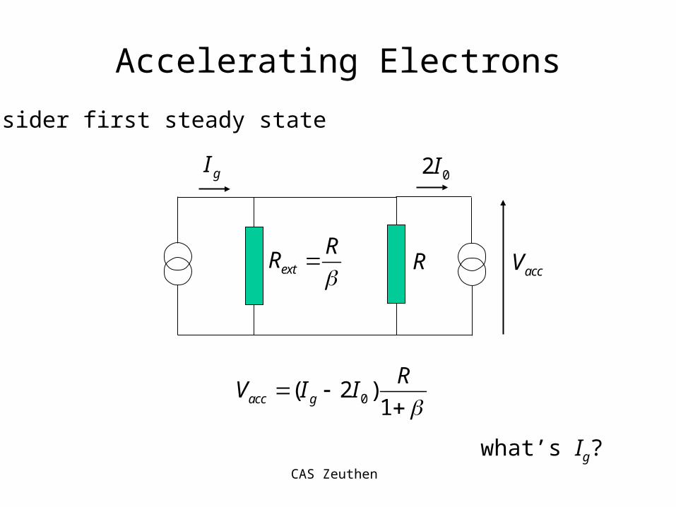
consider first steady state
ext
RR
R
gI02I
accV
0( 2 )1acc g
RV I I
what’s Ig?
CAS Zeuthen
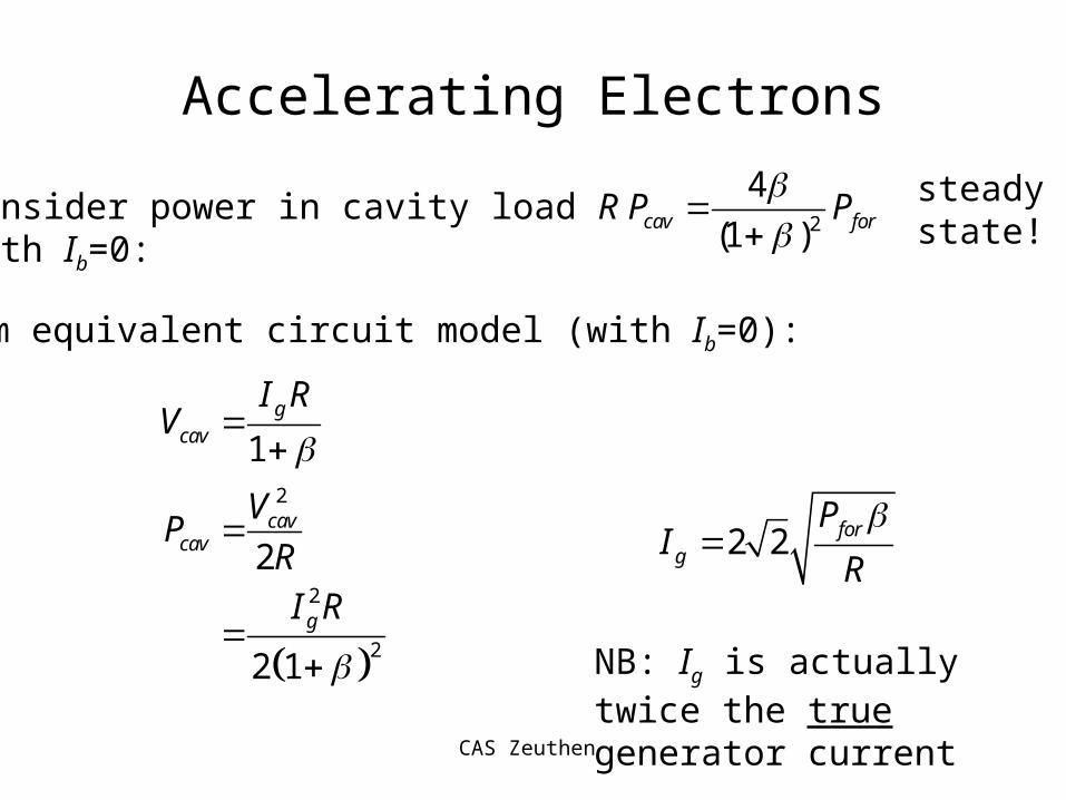
Accelerating Electrons
Consider power in cavity load Rwith Ib=0:
2
4
(1 )cav forP P
From equivalent circuit model (with Ib=0):
2
2
2
1
2
2 1
gcav
cavcav
g
I RV
VP
R
I R
2 2 forg
PI
R
NB: Ig is actually twice the true generator current
steadystate!

CAS Zeuthen
Accelerating Electrons
substituting for Ig:
0( 2 )1acc g
RV I I
0
0
2 2 21
1 2 22 1
foracc
forfor
P RV I
R
RI P R
P
introducing 02 for
RK I
P
22 1
1for
acc
P RKV
beam loading parameter

CAS Zeuthen
Accelerating Electrons
Now let’s calculate the RFbeam efficiency
power fed to beam: 0
41
1beam acc for
K KP I V P
hence:4
11
beamRF beam
for
KP K
P
reflected power: 2
2
12
1 2
1
accref for beam cav for
for
VP P P P P
R
KP

CAS Zeuthen
Accelerating Electrons
Note that if beam is off (K=0)2
1
1ref forP P
For zero-beam loading case, we needed = 1 for maximum power transfer (i.e. Pref = 0)
Now we require 0 1 2
1
2
K
K
Hence for a fixed coupler (), zero reflection only achieved at one specific beam current.
previous result

CAS Zeuthen
A Useful Expression for
1opt
s foracc
r PV
efficiency:4
11
beamRF beam
for
KP K
P
1
2K
optimum
voltage:
1 sopt
beam
r
r
can show
where
0/beam accr V I
0
12 1
2 1s
acc for sfor
rV I P r
P

CAS Zeuthen
Example: TESLA
10
0
2 10
3.2nC
337ns
9.5mA
b
b
b
N
Q
t
I
0
100
13
1.3GHz
/ 1kΩ
10
10
s
s
f
r Q
Q
r
beam current: cavity parameters (at T = 2K):
25MVaccV
For optimal efficiency, Pref = 0:
0
2
237.5kW
62.5 W
99.97%
for beam cav
beam acc
acccav
s
RF beam
P P P
P I V
VP
r
cw!From previous results:
30.8
3804
K

CAS Zeuthen
Unloaded Voltage
for sloaded
P rV
1
2K
matched condition:
2
1unloaded for sV P r
for , 1K
2
1
2
unloaded
loaded
V
V
hence:

CAS Zeuthen
Pulsed Operation
/( ) 2 1 tcav accV t V e
0
0 0
22
1L QQ
( ) /
0( )
1 fill
fill
t tbeamacc fill
t tV t
V e t t
Allow cavity to charge for tfill such that
( ) ln(2)cav fill acc fillV t V t
For TESLA example: 645 s 447 sfillt
From previous discussions:

CAS Zeuthen
0 500 1000 1500 2000 25000
0.2
0.4
0.6
0.8
1
Pulse Operation
0 500 1000 1500 2000 250020
10
0
10
20
30
40generatorvoltage
cavityvoltage
beaminducedvoltage
t/s
beam on
reflected power:/ref forP P
• After tfill, beam is introduced
• exponentials cancel and beam sees constant accelerating voltage Vacc= 25 MV
• Power is reflected before and after pulse
RF on
2
0
2( ) 1 exp / 2 1
1ref L forP t t Q P

CAS Zeuthen
Pulsed Efficiency
950 s99.97%
446 s+950 s
68%
beampulse
fill beam
t
t t
total efficiency must include tfill:
for TESLA

CAS Zeuthen
Quick Summary
1beamcw
for
beamcw
fill beam
P
P
t
t t
ln(2)fill Lt 1
0
0 0 0 0 0
22 2
(1 )s accL
L
Q r VQ
Q I
cw efficiency for s.c. cavity:
efficiency for pulsed linac:
fill time:
Increase efficiency (reduce fill time):
• go to high I0 for given Vacc
• longer bunch trains (tbeam)
some other constraints:
• cyrogenic load
• modulator/klystron
2acc rep pulseV f t

CAS Zeuthen
Lorentz-Force Detuning
In high gradient structures, E and B fields exert stress on the cavity, causing it to deform.
detuning of cavity
As a result:• cavity off resonance by relative
amount = /0
• equivalent circuit is now complex• voltage phase shift wrt generator
(and beam) by• power is reflected
2 2
Re1 2
1 4
accacc
L
acc
L
VV
iQ
V
Q
1tan 2 LQ
require 3
3 22
1010
4acc L
V
V Q
= few Hz for TESLA
For TESLA 9 cell at 25 MV, f ~ 900 Hz !! (loaded BW ~500Hz)[note: causes transient behaviour during RF pulse]

CAS Zeuthen
Lorentz Force Detuning cont.
recent tests on TESLA high-gradient cavity
2
21Hz/(MV/m)
f k E
k

CAS Zeuthen
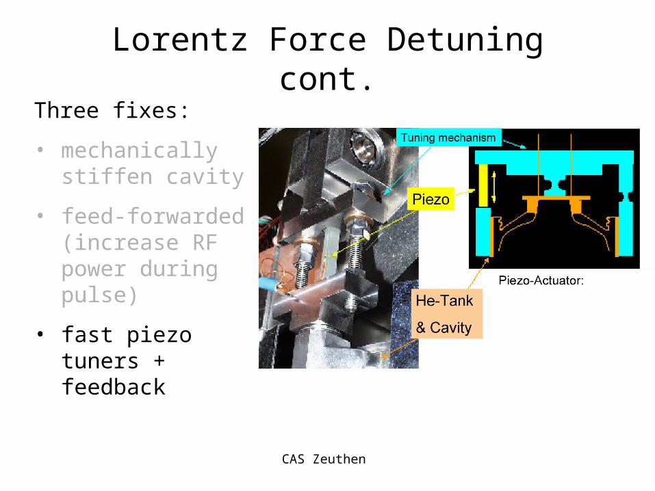
Lorentz Force Detuning cont.
Three fixes:
• mechanically stiffen cavity
• feed-forwarded (increase RF power during pulse)
• fast piezo tuners + feedback

CAS Zeuthen
Lorentz Force Detuning cont.
Three fixes:
• mechanically stiffen cavity
• feed-forwarded (increase RF power during pulse)
• fast piezo tuners + feedback
stiffening ringreduces effect by ~1/2

CAS Zeuthen
Lorentz Force Detuning cont.
Three fixes:
• mechanically stiffen cavity
• feed-forwarded (increase RF power during pulse)
• fast piezo tuners + feedback
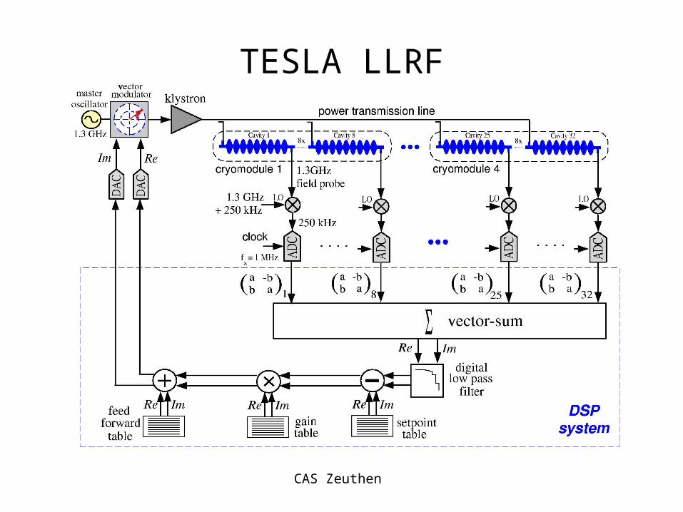
Low Level RF (LLRF) compensates.Mostly feedforward (behaviour is repetitive)For TESLA, 1 klystron drives 36 cavities, thus ‘vector sum’ is corrected.
CAS Zeuthen
Lorentz Force Detuning cont.
Three fixes:
• mechanically stiffen cavity
• feed-forwarded (increase RF power during pulse)
• fast piezo tuners + feedback
CAS Zeuthen
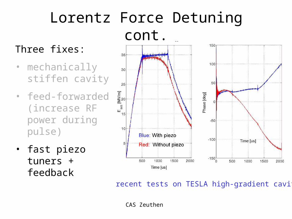
Lorentz Force Detuning cont.
Three fixes:
• mechanically stiffen cavity
• feed-forwarded (increase RF power during pulse)
• fast piezo tuners + feedback
recent tests on TESLA high-gradient cavity

CAS Zeuthen
Wakefields and Beam Dynamics
• bunches traversing cavities generate many RF modes.
• Excitation of fundamental (0) mode we have already discussed (beam loading)
• higher-order (higher-frequency) modes (HOMs) can act back on the beam and adversely affect it.
• Separate into two time (frequency) domains:– long-range, bunch-to-bunch
– short-range, single bunch effects (head-tail effects)

CAS Zeuthen
Wakefields: the (other) SC RF Advantage
• the strength of the wakefield potential (W) is a strong function of the iris aperture a.
• Shunt impedance (rs) is also a function of a.
• To increase efficiency, Cu cavities tend to move towards smaller irises (higher rs).
• For S.C. cavities, since rs is extremely high anyway, we can make a larger without loosing efficiency.
2a
significantly smaller wakefields
3W a

CAS Zeuthen
Long Range Wakefieldstb
( , ) ( , ) ( , )V t I t Z t Bunch ‘current’ generates wake that decelerates trailing bunches.
Bunch current generates transverse deflecting modes when bunches are not on cavity axis
Fields build up resonantly: latter bunches are kicked transversely
multi- and single-bunch beam break-up (MBBU, SBBU)
wakefield is the time-domain description of impedance
CAS Zeuthen
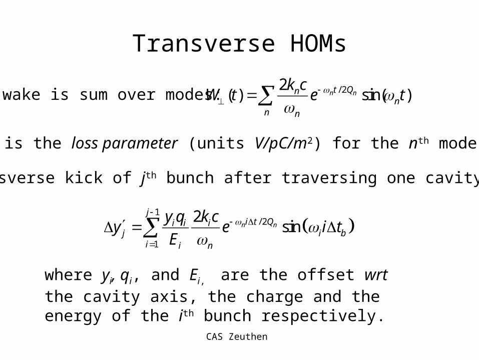
Transverse HOMs
/ 22( ) sin( )n nt Qn
nn n
k cW t e t
wake is sum over modes:
kn is the loss parameter (units V/pC/m2) for the nth mode
Transverse kick of jth bunch after traversing one cavity:
1
/ 2
1
2sinn n
ji t Qi i i
j i bi i n
y q k cy e i t
E
where yi, qi, and Ei, are the offset wrt the cavity axis, the charge and the energy of the ith bunch respectively.

CAS Zeuthen
10 100 1000 10000 100000.0.001
0.01
0.1
1
10
100
10 100 1000 10000 100000.0.001
0.01
0.1
1
10
100
Detuning
abs.
wak
e (V
/pC
/m)
abs.
wak
e (V
/pC
/m)
time (ns)
no detuningHOMs cane be randomly detuned by a small amount.
Over several cavities, wake ‘decoheres’.
with detuningEffect of random 0.1%detuning(averaged over 36 cavities).
next bunch
Still require HOM dampers

CAS Zeuthen
Effect of Emittance
vertical beam offset along bunch train(nb = 2920)
Multibunch emittance growth for cavities with 500m RMS misalignment

CAS Zeuthen
Single Bunch Effects
• Completely analogous to low-range wakes• wake over a single bunch• causality (relativistic bunch): head of bunch affects
the tail• Again must consider
– longitudinal: effects energy spread along bunch
– transverse: the emittance killer!
• For short-range wakes, tend to consider wake potentials (Greens functions) rather than ‘modes

CAS Zeuthen
Longitudinal Wake
( )W z ctConsider the TESLA wake potential
3
V( ) 38.1 1.165exp 0.165
pC m 3.65 10 [m]
sW z
, ( ) ( ) ( )bunch
z z
W z W z z z dz
wake over bunch given by convolution:
4 2 0 2 4
20
15
10
5
0
V/p
C/m
z/z
300μmz
headtailaverage energy loss:
, ( ) ( )b bunchE q W z z dz
((z) = long. charge dist.)
For TESLA LC: 46 kV/mE

CAS Zeuthen
RMS Energy Spread
4 2 0 2 4
10
8
6
4
26
0 2 4 6 8 10 12
0.3
0.4
0.5
0.6
0.7
0.8
0.9
z/z
rms
E/E
(pp
m)
E/E
(pp
m) RF
wake+RF
(deg)
accelerating field along bunch:
, 0( ) ( ) cos(2 / )b bunch RFE z q W z E z
Minimum energy spread along bunch achieved when bunch rides ahead of crest on RF.
Negative slope of RF compensates wakefield.
For TESLA LC, minimum at about ~ +6º

CAS Zeuthen
RMS Energy Spread

CAS Zeuthen
Transverse Single-Bunch Wakes
When bunch is offset wrt cavity axis, transverse (dipole) wake is excited.
1000 500 0 500 10000
2000
4000
6000
8000
V/pC/m2
z/z
headtail
‘kick’ along bunch:
( ) ( ' ) ( ) ( ; )( )b
z z
qy z W z z z y s z dz
E z
Note: y(s; z) describes a free betatronoscillation along linac (FODO) lattice(as a function of s)

CAS Zeuthen
2 particle model
Effect of coherent betatron oscillation
- head resonantly drives the tail2
1 1 0y k y
head eom (Hill’s equation):
tail eom:head
tail
1 0( ) ( ) sin ( )y s a s s
solution:
resonantly driven oscillator
22 2 1
' 22 z
beam
qW
y k y yE

CAS Zeuthen
BNS DampingIf both macroparticles have an initial offset y0 then particle 1 undergoes a sinusoidal oscillation, y1=y0cos(kβs). What happens to particle 2?
2 0
'cos sin
2z
beam
W qy y k s s k s
k E
Qualitatively: an additional oscillation out-of-phase with the betatron term which grows monotonically with s.
How do we beat it? Higher beam energy, stronger focusing, lower charge, shorter bunches, or a damping technique recommended by Balakin, Novokhatski, and Smirnov (BNS Damping) curtesy: P. Tenenbaum (SLAC)

CAS Zeuthen
BNS DampingImagine that the two macroparticles have different betatron frequencies, represented by different focusing constants kβ1 and kβ2
The second particle now acts like an undamped oscillator driven off its resonant frequency by the wakefield of the first. The difference in trajectory between the two macroparticles is given by:
2 1 0 2 12 22 1
' 11 cos cosz
beam
W qy y y k s k s
E k k
curtesy: P. Tenenbaum (SLAC)

CAS Zeuthen
BNS DampingThe wakefield can be locally cancelled (ie, cancelled at all points down the linac) if:
2 22 1
' 11z
beam
W q
E k k
This condition is often known as “autophasing.”
It can be achieved by introducing an energy difference between the head and tail of the bunch. When the requirements of discrete focusing (ie, FODO lattices) are included, the autophasing RMS energy spread is given by:
2
2
'1
16 sincellE z
beam beam
LW q
E E
curtesy: P. Tenenbaum (SLAC)

CAS Zeuthen
Wakefields (alignment tolerances)
bunch
0 km 5 km 10 km
head
head
headtailtail
tail
accelerator axis
cavities
y
tail performsoscillation
2 221fc
i
EN Wy
E
CAS Zeuthen
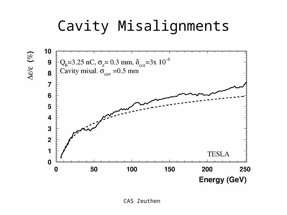
Cavity Misalignments

CAS Zeuthen
Wakefields and Beam Dynamics
The preservation of (RMS) Emittance!
Quadrupole Alignment Structure Alignment
Wakefields
Dispersion
controlof
Transverse
Longitudinal
E/E
beam loading
Single-bunch

CAS Zeuthen
Emittance tuning in the Linac
• DR produces tiny vertical emittances (y ~ 20nm)
• LINAC must preserve this emittance!– strong wakefields (structure misalignment)
– dispersion effects (quadrupole misalignment)
• Tolerances too tight to be achieved by surveyor during installation
Need beam-based alignment
mma!
Consider linear collider parameters:
CAS Zeuthen
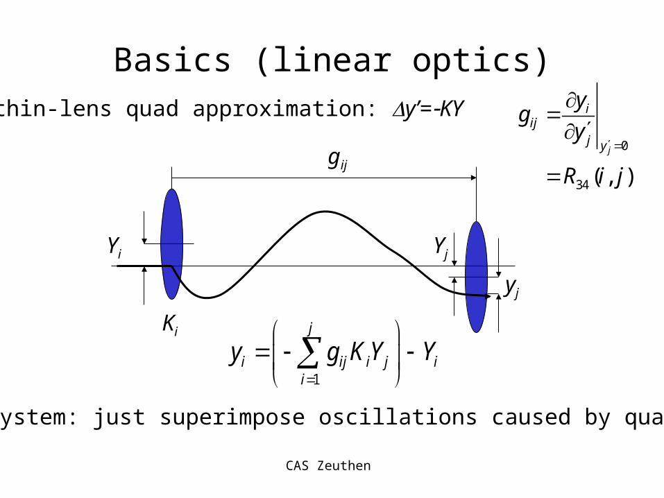
YjYi
Ki
yj
gij
1
j
i ij i j ii
y g K Y Y
Basics (linear optics)
0
34 ( , )j
iij
j y
yg
y
R i j
linear system: just superimpose oscillations caused by quad kicks.
thin-lens quad approximation: y’=KY

CAS Zeuthen
1
j
i ij i j ii
y g K Y Y
YQy
Idiag(K)GQ
Original Equation
Defining Response Matrix Q:
Hence beam offset becomes
Introduce matrix notation
21
31 32
41 42 43
0 0 0 0
0 0 0
0 0
0
g
g g
g g g
G
G is lower diagonal:

CAS Zeuthen
Dispersive Emittance Growth
Consider effects of finite energy spread in beam RMS
( ) ( )1
K
Q G diag Ichromatic response matrix:
latticechromaticity
dispersivekicks0
34 34 346
( ) (0)
( ) (0)R R T
GG G
dispersive orbit: ( )( ) (0)y
Δy
η Q Q Y

CAS Zeuthen
What do we measure?BPM readings contain additional errors:
boffset static offsets of monitors wrt quad centres
bnoise one-shot measurement noise (resolution RES)
0BPM offset noise 0 0
0
y
y
y Q Y b b R y y
fixed fromshot to shot
random(can be averaged
to zero)launch condition
In principle: all BBA algorithms deal with boffset

CAS Zeuthen
Scenario 1: Quad offsets, but BPMs aligned
BPM
Assuming:
- a BPM adjacent to each quad
- a ‘steerer’ at each quad
simply apply one to one steering to orbit
steererquad mover
dipole corrector

CAS Zeuthen
Scenario 2: Quads aligned, BPMs offset
BPM
1-2-1 corrected orbit
one-to-one correction BAD!
Resulting orbit not Dispersion Free emittance growth
Need to find a steering algorithm which effectively puts BPMs on (some) reference line
real world scenario: some mix of scenarios 1 and 2

CAS Zeuthen
BBA• Dispersion Free Steering (DFS)
– Find a set of steerer settings which minimise the dispersive orbit
– in practise, find solution that minimises difference orbit when ‘energy’ is changed
– Energy change: • true energy change (adjust linac phase)• scale quadrupole strengths
• Ballistic Alignment– Turn off accelerator components in a given section,
and use ‘ballistic beam’ to define reference line– measured BPM orbit immediately gives boffset wrt to
this line

CAS Zeuthen
DFS
( ) (0)E E
E E
E
E
Δy Q Q Y
M Y
1 Y M Δy
Problem:
Solution (trivial):
Note: taking difference orbit y removes boffset
Unfortunately, not that easy because of noise sources:
noise 0 Δy M Y b R y

CAS Zeuthen
DFS example300m randomquadrupole errors
20% E/E
No BPM noise
No beam jitter
m
m
CAS Zeuthen
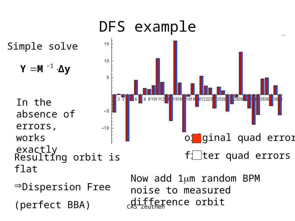
DFS exampleSimple solve
1 Y M Δy
original quad errors
fitter quad errors
In the absence of errors, works exactly
Resulting orbit is flat
Dispersion Free
(perfect BBA)
Now add 1m random BPM noise to measured difference orbit

CAS Zeuthen
DFS exampleSimple solve
1 Y M Δy
original quad errors
fitter quad errorsFit is ill-conditioned!
CAS Zeuthen
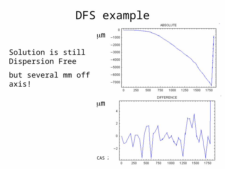
DFS example
m
m
Solution is still Dispersion Free
but several mm off axis!
CAS Zeuthen
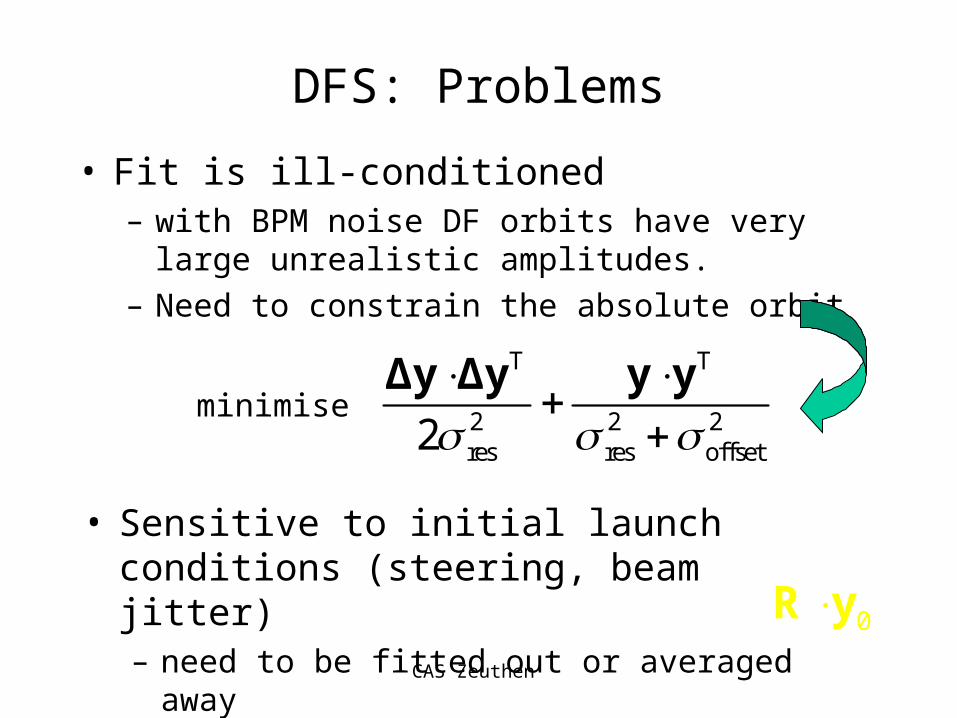
DFS: Problems
• Fit is ill-conditioned– with BPM noise DF orbits have very large unrealistic
amplitudes.
– Need to constrain the absolute orbit
T T
2 2 2res res offset2
Δy Δy y y
minimise
• Sensitive to initial launch conditions (steering, beam jitter)– need to be fitted out or averaged away 0R y

CAS Zeuthen
DFS exampleMinimise
original quad errors
fitter quad errors
T T
2 2 2res res offset2
Δy Δy y y
absolute orbit now
constrained
remember
res = 1m
offset = 300m
CAS Zeuthen
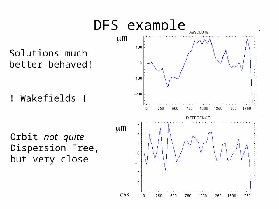
DFS examplem
m
Solutions much better behaved!
! Wakefields !
Orbit not quite Dispersion Free, but very close
CAS Zeuthen
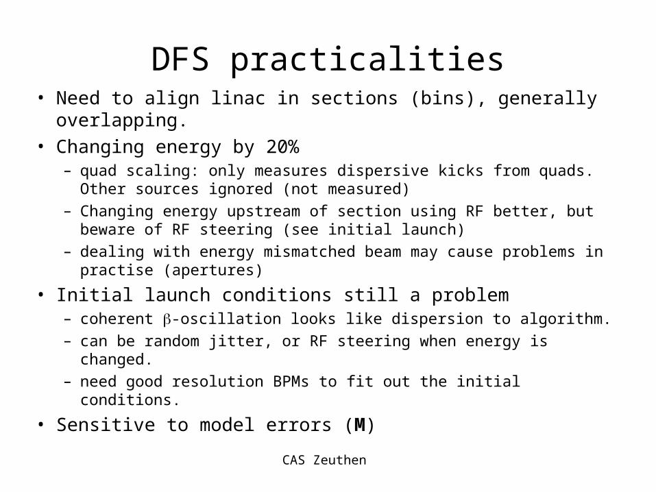
DFS practicalities• Need to align linac in sections (bins), generally overlapping.
• Changing energy by 20%– quad scaling: only measures dispersive kicks from quads. Other sources
ignored (not measured)
– Changing energy upstream of section using RF better, but beware of RF steering (see initial launch)
– dealing with energy mismatched beam may cause problems in practise (apertures)
• Initial launch conditions still a problem– coherent -oscillation looks like dispersion to algorithm.
– can be random jitter, or RF steering when energy is changed.
– need good resolution BPMs to fit out the initial conditions.
• Sensitive to model errors (M)

CAS Zeuthen
Ballistic Alignment• Turn of all components in section to be aligned [magnets,
and RF]
• use ‘ballistic beam’ to define straight reference line (BPM
offsets)
• Linearly adjust BPM readings to arbitrarily zero last BPM
• restore components, steer beam to adjusted ballistic line
62
BPM, 0 0 offset, noise,i i i iy y s y b b
CAS Zeuthen
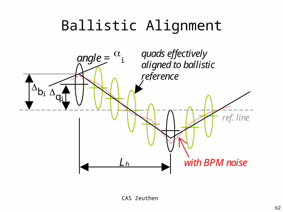
Ballistic Alignment
bi qi
Lb
quads effectively aligned to ballistic reference
angle = i
ref. line
with BPM noise
62

CAS Zeuthen
Ballistic Alignment: Problems• Controlling the downstream beam during
the ballistic measurement– large beta-beat– large coherent oscillation
• Need to maintain energy match – scale downstream lattice while RF in ballistic
section is off
• use feedback to keep downstream orbit under control
CAS Zeuthen
TESLA LLRF