Embed Size (px)
Citation preview

02/01/2017 1
Replacing the Check Stand Motor
Carousel Unit User Manual

2
Table of Contents Tools: .................................................................................................................. 3
Turn Off Power to the Unit: ................................................................................ 4
Remove Power Switch ........................................................................................ 5
Remove Electric Eyes: ......................................................................................... 6
Remove POS (Point-Of-Sale) Assembly: .............................................................. 7
Remove & Replace Motor: .................................................................................. 9
Remove and Replace the Capacitor: .................................................................. 18
Re-assemble the Unit ........................................................................................ 23
Check the Belt Alignment: ................................................................................. 27
CONTACT INFORMATION .................................................................................. 30

3
Tools You Will Need:
1. Power driver with a Phillips bit, special bit, and 7/16” socket
2. Flat head screwdriver
3. Wire cutters
4. 1/8” zip ties
The image below shows the Belted, Carousel Check Out Stand. This instruction will demonstrate how to remove and replace the motor and capacitor. A new capacitor will be included with the new motor; thus, it will be necessary to replace the capacitor simultaneously with the motor.

4
Turn Off Power to the Unit:
1. Remove two screws holding the access panel on the customer’sside of the Belted Lead-In.
2. Remove the accesspanel, exposing theMain Power Cord.Unplug the cord fromthe Power Pole.
NOTE: Retain all hardware for later re-installation.

5
Remove Power Switch
1. Remove two screws holding the Power Switch on the clerk’s sideof the Belted Lead-In. Gently pry up and pull out the switch.
2. Use the blade of a flathead screwdriver tocarefully separate theBelt Switch Platefrom the wires.
3. Use caution to avoiddamaging the wires.

02/01/2017 – Rev-
6
Remove Electric Eyes:
2. Push the cable from underneath the unit rather than pulling onthe wires, which could damage the Molex connector.
1. Both the Sender and Receiver Eyes may be removed using thesame steps, which follow. Remove two screws and pull out theElectric Eye casing (receiver shown).

7
Remove POS (Point-Of-Sale) Assembly:
1. Inside thehardware packageprovided is aspecial bitrequired toremove the POSAssembly.
2. Using a power driverwith the special bit,remove four boltsholding the POSAssembly to the rail(two on the front andtwo on the back). Liftand remove the POSAssembly. Set aside.

8
3. Unscrew and remove the stainless-steel trim rails from both thecustomer’s and cashier’s sides of the unit.

9
Remove & Replace Motor:
1. Remove the twoscrews at thebottom of the nosecover.
2. Pull up on the nose cover. There may be a tight fit; if so, lift up,pull back and lift up again.

10
3. The edges of the nose cover are slotted to connect to screws on theinside of each rail.
4. Using a power driver with a Phillips bit, remove the two screwsholding the Dead plate. Remove the Dead plate.

11
5. Using a power driver with a Phillips bit, remove the four screws holdingthe Dead Plate Support, indicated by the red arrows below.
6. After removing the four screws, lift the Dead Plate Support out andaway.
12
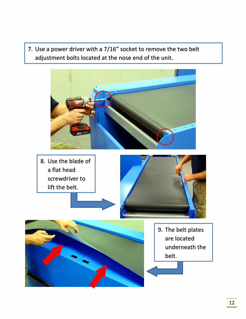
7. Use a power driver with a 7/16” socket to remove the two beltadjustment bolts located at the nose end of the unit.
8. Use the blade ofa flat headscrewdriver tolift the belt.
9. The belt platesare locatedunderneath thebelt.

13
11. Note that the belt platesare held in place by thebelt plate hooks.
10. There are fingerslots in the cornersof each belt plate.Use these to lift andremove the beltplates from theunit.
12. Carefully lift themotor cylinder upand slide the beltaway.

14
13. Replace the cylinder, being careful not to damage the Electric Eyewires.
14. Pull the belt back toward the nose of the unit and leave it foldedand out of the way while performing the following steps.

15
16. Dislodge the motor cable from the cable holders and remove themotor.
15. Trace the motor cable to the capacitor. Reach underneath theCapacitor Housing and disconnect the cable. The four-prongedconnector has a hook that must be pressed before it can beremoved.

16
17. Obtain a new Motor Cylinder. Feed the motor cable through theopening in the mounting slots so that the cable may be attachedto the cable holders and the Controller.
17
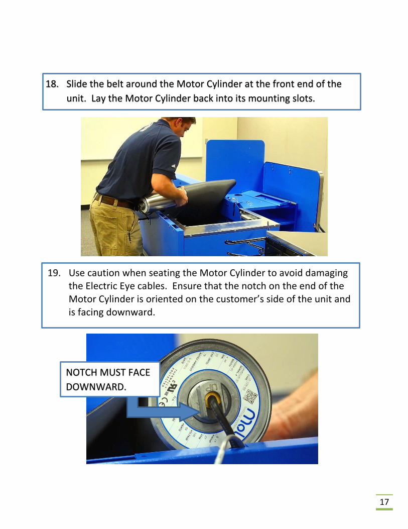
18. Slide the belt around the Motor Cylinder at the front end of theunit. Lay the Motor Cylinder back into its mounting slots.
19. Use caution when seating the Motor Cylinder to avoid damagingthe Electric Eye cables. Ensure that the notch on the end of theMotor Cylinder is oriented on the customer’s side of the unit andis facing downward.
NOTCH MUST FACE DOWNWARD.

18
Remove and Replace the Capacitor:
1. Disconnect the three additional cables that are attached to theside of the Capacitor Housing. The black cable with two wires isthe switch cable. The gray cables with two and four wires areboth for the electric eyes.
2. Using a power driver with a Phillips bit, remove the small screwholding the Capacitor Housing to the base. Retain all hardware.

19
3. Grasp and pull the Capacitor Housing free from the base.
4. Remove the four screws from the bottom of the Capacitor Housing.Open the Housing to expose the Capacitor. Retain all hardware.
CAPACITOR

20
7. Obtain the new Capacitor and reconnect the wires from the previousstep. Ensure that the wires are connected on opposite corners, asshown below.
5. Using wire cutters, severthe zip ties that hold theCapacitor in place
6. Use the blade of aflat headscrewdriver torelease the femalequick disconnectsattached to theCapacitor.

21
10. Plug the Capacitor Housing back into the base. Replace the screwremoved in Step 3.
8. Return theCapacitor to theHousing andsecure in placeusing 1/8” zipties.
9. Close the Housingand reinstall thefour screwsremoved in Step 5.

22
11. Reconnect the electric eyeand switch cables to theCapacitor Housing. Theswitch cable goes in thetop position, followed bythe 2-wire and 4-wireelectric eye cables.
12. Reconnect the motorcable to the underside ofthe Capacitor Housing.
23
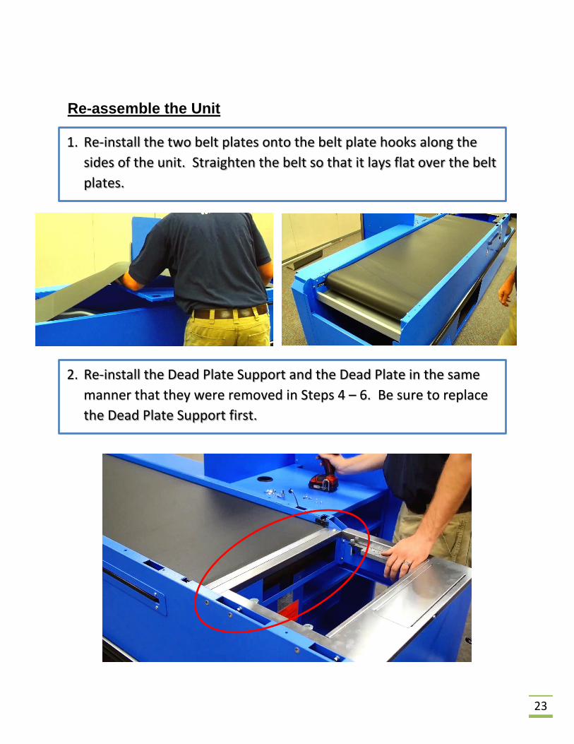
Re-assemble the Unit
1. Re-install the two belt plates onto the belt plate hooks along thesides of the unit. Straighten the belt so that it lays flat over the beltplates.
2. Re-install the Dead Plate Support and the Dead Plate in the samemanner that they were removed in Steps 4 – 6. Be sure to replacethe Dead Plate Support first.

24
3. Replace thestainless-steel trimalong the unit rails.Feed the PowerSwitch cablethrough theopening in the trimand re-connect thePower Switch.
4. Attach the Power Switch to the rail using the two screws removedin Step 1 on Page 5. Before tightening, ensure the switch isoriented so that it is legible from the cashier’s position.

25
5. Replace andtighten all of theremaining trimscrews.
6. Replace theElectric Eyes byfeeding the wiresthrough the slots.Do not pull or tugon the wires, asthey may becomedamaged.7. Re-attach the
Electric Eyes to theunit using thescrews retained atremoval. Becareful not to stripthe screws.

26
8. Re-install the two belt adjustment bolts into the nose end of the unit.Use a 7/16” socket to tighten the belt. It is necessary to tighten eachside just a bit at a time so that the belt is tightened evenly.
9. Re-connect the power cord to the power pole to restore power to theunit.

27
Check the Belt Alignment:
1. Turn on the beltpower and checkeach of the corners toensure that the belt isnot touching the siderails.
2. When the automatictime-out causes thebelt to stop, you canbreak the plane ofthe Electric Eyes tostart the belt again.
3. To extend the running time ofthe belt while makingadjustments, open the Lead-In’saccess panel and locate theController Assembly.

28
4. A button marked “TestRun” is located next tothe LED light. Pressingthis button will cause thebelt to run for longerthan two minutes.
5. If it is necessary to adjust the belt, use the adjustment bolts located atthe nose end on the customer’s side and cashier’s side.

29
6. Use a 7/16” socket wrench to make adjustments. Adjusting thebolt left will loosen the belt tension and cause the belt to drifttoward the side you are adjusting. Adjust the bolt to the right,the belt tension increases and causes the belt to drift away fromthe adjustment side.
7. After making an adjustment, allow belt to run at least five (5)minutes before making further adjustments so as not to “over-adjust” the belt.
8. Re-install the nose cover and screws. Replace Lead-In accesspanel.

Replace Check Stand Motor 02/01/2017 30
CONTACT INFORMATION:
If you have any questions about the contents of this instruction sheet, please do not hesitate to contact us.
Your Royston Customer Service Team is ready to help you.
1-800-334-1766
9. Re-install the POS onto the rail and secure using the four boltsremoved in Step 2 on Page 7. Recall that these bolts will requirethe special bit included in the hardware package.