Embed Size (px)
Citation preview

1
ITALIANO
ENGLISH
FRANÇAIS
DEUTSCH
ESPAÑOLATTENTION! Before installing this device read the following instructions carefully!
Installation example Pages 3-4Standard wiring diagram Page 5Important remarks Page 14Installation instructions Pages 15-16Manual release mechanism Page 16Electrical connection Pages 16-17Programming procedure Page 18-20Automatic repositioning Page 20Remote control Page 20Function modes Pages 21Battery powered operation Page 21Technical specifications Page 44
ATTENTION! Avant de commencer la pose, lire atten-tivement les instructions!
Exemple d’installation Pages 3-4Schéma électrique de l'exemple d'installation Page 5Consignes importantes Page 22Instructions pour l’installation Pages 23-24Manoeuvre manuelle Page 24Branchement électrique Pages 24-25Procédé de programmation Page 26-28Repositionnement automatique Page 28Commande par radio Page 28Modes de fonctionnement Pages 29Fonctionnement de à batterie Page 29Caractéristiques techniques Page 44
ACHTUNG! Bevor mit der Installation begonnen wird, sollte die Anleitung aufmerksam gelesen werden.
Anlagenart Seiten 3-4Elektrischer Schaltplan Anlagenart Seite 5Wichtige Hinweise Seite 30Installationsanleitung Seiten 31-32Manuelle Betätigung Seite 32Elektrischer Anschluss Seiten 32-33Programmierverfahren Seite 34-36Automatische Rückstellung Seite 36Fernbedienung Seite 36Funktionsart Seiten 37Batteriebetrieb Seite 37Technische Eigenschaften Seite 44
¡ATENCIÓN! Antes de iniciar la instalación del sistema, leer atentamente las instrucciones.
Instalación estándar Páginas 3-4Esquema eléctrico instalación estándar Página 5 Advertencias importantes Página 38Instrucciones para la instalación Páginas 39-40Maniobra manual Página 40Conexionado eléctrico Páginas 40-41Procedimiento para la programación Página 42-44Reposicionamiento automático Página 44Mando vía radio Página 44Modalidad de funcionamiento Páginas 45Funcionamiento por batería Página 45Características técnica Página 44
ZV
L554
.00
Mod
: 27-
11-2
014
ATTENZIONE! Prima di iniziare l'installazione leggere le istruzioni attentamente!
Verifiche preliminari/Impianto tipo Pagine 3-4Schema elettrico impianto tipo Pagina 5Avvertenze importanti Pagina 6Istruzioni per l'installazione Pagine 7-8Sblocco manuale Pagina 8Collegamento elettrico Pagine 8-9Procedura di programmazione Pagina 10-12 Riposizionamento automatico Pagina 12Comando via radio Pagina 12Modalità di funzionamento Pagine 13Funzionamento a batteria Pagina 13Caratteristiche tecniche Pagina 44
24 Vdc Motors 105/SLi824 (V0.11)
Questo prodotto è stato testato e collaudato nei laboratori della casa costruttrice, la quale ne ha verificato la perfetta corrispondenza delle caratteristiche con quelle richieste dalla normativa vigente. This product has been tried and tested in the manufacturer's laboratory who have verified that the product conforms in every aspect to the safety standards in force. Ce produit a été testé et essayé dans les laboratoires du fabriquant. Pour l'installer suivre attentivement les instructions fournies. Dieses Produkt wurde in den Werkstätten der Herstellerfirma auf die perfekte Übereinstimmung ihrer Eigenschaften mit den von den geltenden Normen vorgeschriebenen getestet und geprüft. Este producto ha sido probado y ensayado en los laboratorios del fabricante, que ha comprobado la perfecta correspondencia de sus características con las contempladas por la normativa vigente.
SL24VdcMotors
Model DateInstruction manual Series
-CARDIN ELETTRONICA spa Via del lavoro, 73 – Z.I. Cimavilla 3 1 0 1 3 C o d o g n è ( T V ) I t a l yTel: +39/0438.404011Fax: +39/0438.401831email (Italian): [email protected] (Europe): [email protected]: www.cardin.it
Targhetta CARDIN INSIDE
20-05-2008
ZVE542 Description :
Product Code :
Date :
Drawing number :
P.J.Heath
CARDIN ELETTRONICA S.p.A - 31020 San Vendemiano (TV) Italy - via Raffaello, 36 Tel: 0438/401818 Fax: 0438/401831
Draft :
All rights reserved. Unauthorised copying or use of the information contained in this document is punishable by law
Targhetta metallica per propulsori integrabili
colore grigio - pantone 424C (C0 - M0 - Y0 - K61)
colore rosso - pantone 485C (C0 - M95 - Y100 - K0)
AUTOMAZIONE INTEGRATE PER CANCELLI SCORREVOLIINTEGRATED AUTOMATION FOR SLIDING GATESAUTOMATISME INTÉGRÉ POUR PORTAILS COULISSANTSINTEGRIERTE SCHIEBETORANTRIEBEAUTOMATIZACIÓN INTEGRADO PARA CANCILLAS CORREDERAS
SLi824 15-07-2014ZVL554.00

2
The CE conformity declaration for Cardin products is available in original language from the site www.cardin.it under the section "Standards and Certification".Les déclarations de conformité CE des produits Cardin sont disponibles dans la langue originale sur le site www.cardin.it dans la section "normes et certificats".Die CE-Konformitätserklärungen für die Cardin-Produkte stehen in der Originalsprache auf der Homepage www.cardin.it im Bereich "Normen und Zertifizierung" zur Verfügung.Las declaraciones de conformidad CE de los productos Cardin se encuentran disponibles en el idioma original en el sitio www.cardin.it en la sección "normas y certificaciones".
SLi824 24 Vdc 16-07-2014DCE090
x x x x x x x x x x x x x x x x x x x x x x x x x x x x x x x x x x x x x x x x x x x x x x x x x x x x x x x x x x
x x x x x x x x x x x x x x x x x x x x x x x x x x x x x x x x x x x x x x x x x x x x x x x x x x x x x x x x x x
x x x x x x x x x x x x x x x x x x x x x x x x x x x x x x x x x x x x x x x x x x x x x x x x x x x x x x x x x x
x x x x x x x x x x x x x x x x x x x x x x x x x x x x x x x x x x x x x x x x x x x x x x x x x x x x x x x x x x
x x x x x x x x x x x x x x x x x x x x x x x x x x x x x x x x x x x x x x x x x x x x x x x x x x x x x x x x x x
x x x x x x x x x x x x x x x x x x x x x x x x x x x x x x x x x x x x x x x x x x x x x x x x x x x x x x x x x
x x x x x x x x x x x x x x x x x x x x x x x x x x x x x x x x x x x x x x x x x x x x x x x x x x x x x x x x x x
x x x x x x x x x x x x x x x x x x x x x x x x x x x x x x x x x x x x x x x x x x x x x x x x x x x x x x x x x x
x x x x x x x x x x x x x x x x x x x x x x x x x x x x x x x x x x x x x x x x x x x x x x x x x x x x x x x x x x
x x x x x x x x x x x x x x x x x x x x x x x x x x x x x x x x x x x x x x x x x x x x x x x x x x x x x x x x x x
x x x x x x x x x x x x x x x x x x x x x x x x x x x x x x x x x x x x x x x x x x x x x x x x x x x x x x x x x x
x x x x x x x x x x x x x x x x x x x x x x x x x x x x x x x x x x x x x x x x x x x x x x x x x x x x x x x x x x
CARDIN ELETTRONICA spa Via del lavoro, 73 – Z.I. Cimavilla 31013 Codognè (TV) ItalyTel.: (+39) 04 38 40 40 11 Fax: (+39) 04 38 40 18 31e-mail (Italy): [email protected] (Europe): [email protected]: www.cardin.it
Il costruttore: CARDIN ELETTRONICA S.p.A. DICHIARA CHE L'APPARECCHIATURA DESTINATA AD ESSERE INSERITA IN MACCHINE E NON FUNZIONANTE IN MODO INDIPENDENTE:
Nome dell'apparato Motoriduttore SLi824Tipo di apparato Automazione a 24 Vdc integrata per cancelli scorrevoli con centralina esternaModello SLi824 + centrale di comando CC824Marchio Cardin ElettronicaAnno di prima fabbricazione 2014
MODELLO DATACODICE SERIE
Dichiarazione di Incorporazione(Direttiva Macchine 2006/42/EC, All. IIB)
e sono state applicate le seguenti norme e/o specifiche tecniche:- EN 55014-1 : 2006+A1:2009+A2:2011- EN 55014-2 : 1997+A1:2001+A2:2008- EN 61000-3-2 : 2006 +A1+A2:2009- EN 61000-3-3 : 2013- EN 301489-3 : 2013 (V1.6.1)- EN 301489-1 : 2011 (V1.9.2)- EN 60335-1 : 2011- EN 60335-2-103 : 2003 + A11 :2009
è conforme alle disposizioni delle seguenti direttive comunitarie:- Direttiva 2004/108/CE (Compatibilità Elettromagnetica)- Direttiva 2006/95/CE (Bassa Tensione)- Direttiva 99/05/CE (R&TTE)
DICHIARA CHE L'APPARECCHIATURA È IDEATA PER ESSERE INCORPORATA IN UNA MACCHINA O PER ESSERE ASSEMBLATA CON ALTRI MACCHINARI PER COSTITUIRE UNA MACCHINA CONSIDERATA DALLA DIRETTIVA 2006/42/CE E SUCCESSIVI EMENDAMENTI.INOLTRE DICHIARA CHE NON È CONSENTITO METTERE IN SERVIZIO L' APPARECCHIATURA FINO A CHE LA MACCHINA NELLA QUALE SARÀ INCORPORATA E DELLA QUALE DIVENTERÀ COMPONENTE NON SIA STATA IDENTIFICATA E DICHIARATA LA CONFORMITÀ ALLE DI-SPOSIZIONI DELLA DIRETTIVA 2006/42/CEE E SUCCESSIVI EMENDAMENTI.
Cardin Elettronica si impegna a trasmettere, in risposta a una richiesta adeguatamente motivata delle autorità nazionali, informazioni pertinenti sulla quasi-macchina in oggetto.
Codognè il 16/07/2014 Persona autorizzata a costituire la documentazione tecnica
Ing. A. Fiorotto (Responsabile tecnico R&D Laboratory)
Rappresentante legale dell'azienda
Dott. Cristiano Cardin (Amministratore delegato)

3
1
2
67
4
53
3
2
ESEMPIO D'INSTALLAZIONE - INSTALLATION EXAMPLE - EXEMPLE D'INSTALLATION - ANLAGENART - INSTALACIÓN ESTÁNDAR
1
LEGENDA1 Motoriduttore2 Fotocellule interne3 Fotocellule esterne4 Programmatore elettronico5 Lampeggiatore6 Antenna esterna7 Costa attiva di sicurezzaAttenzione:Lo schema rappresentato è puramente indicativo e viene fornito come base di lavoro al fine di consentire una scelta dei componenti elettronici Cardin da utilizzare. Detto schema non costituisce pertanto vincolo alcuno per l’esecuzione dell’impianto.
LEGEND1 Geared motor2 Internal photocells3 External photocells4 Electronic programmer5 Warning lights6 External antenna7 Active safety edgeAttention:the drawing is purely indicative and is supplied as working base from which to choose the Cardin electronic components making up the installation. This drawing therefore does not lay down any obligations regarding the execution of the installation.
NOMENCLATURE1 Motoréducteur2 Cellule photoélectrique intérieure3 Cellule photoélectrique extérieure4 Armoire électronique5 Clignoteur6 Antenne7 Bord de sécuritéAttention:le schéma, diffusé à titre purement indicatif, est destiné à vous aider dans le choix des composants électroniques Cardin à utiliser. Par conséquent, il n'a aucune valeur obligatoire quant à la réalisation de l'installation.
ZEICHENERKLÄRUNG1 Getriebemotor2 Interne Lichtschranke3 Externe Lichtschranke4 Elektronische Steuereinheit5 Blinklicht6 Antenne7 SicherheitsleisteAchtung:Bei dem dargestellten Plan handelt es sich nur um ungefähre Angaben und er wird als Arbeitsgrundlage geliefert, um eine Auswahl der zu benutzenden elektronischen Komponenten von Cardin zu erlauben. Der besagte Plan ist daher für die Ausführung der Anlage nicht bindend.
DIMENSIONI D'INGOMBRO - EXTERNAL DIMENSIONSDIMENSIONS D'ENCOMBREMENT - AUSSENABMESSUNGEDIMENSIONES MÁXIMAS
305
100
50
100
80100 2520
Ø68
(4+4) M8
LEYENDA1 Motorreductor2 Fotocélula interior3 Fotocélula exterior4 Centralita electrónica5 Relampagueador6 Antena7 Banda sensibleAtención:la pantalla que se muestra es sólo indicativa y se suministra como base de trabajo, con el fin de permitir una elección de los com-ponentes electrónicos Cardin por utilizar; en consecuencia, dicho esquema no constituye vínculo alguno para la ejecución del sistema.

4
Collegamenti scheda base
CC824
16-07-2014
DI0608 Description :
Product Code :
Date :
Drawing number :
P.J.Heath
CARDIN ELETTRONICA S.p.A - 31020 San Vendemiano (TV) Italy - via Raffaello, 36 Tel: 0438/401818 Fax: 0438/401831
Draft :
All rights reserved. Unauthorised copying or use of the information contained in this document is punishable by law
CC824 INSTALLAZIONE TIPO(con display LCD + manovra di emergenza)
ANS400
SEL
1 32
24V 12V 0
C
1 65432
NA
NC NC
CNA
FTC-RX
1 32
24V12V0
FTC-TX
21
TB
1211109 18171615141387
TB
CM
N
FS FI LP
CM
N
CM
N
CTRL24Vdc
OUT24Vdc
22212019 2423
TA TD
TC
CM
N
21
LP
21
LS
21
TD
TAL
CS1412B DC0546
M1
R1
B1
F3 10 A
F2 10 A
2829
TRANSFORMER
23
14
65
TRF 230Vac
230VacL
N
1211109 18171615141387
22212019 2423
TA TDTC CM
N
TB
CM
N
FS FI LP
CM
N
CM
N
OUT24Vdc
L1
LS
25 26 27
CM
N
EM
RG
2
EM
RG
1
TAL
F4 3.15 A
BC
F1 3.15 A
CTRLOUT
24Vdc
CM
N
CM
N
CP
Enable
Disable1 2 3
J3
Pos.1 Pos.2
1 2 3
CM
N
CPCM
N
LSLCD1
T B
F S
F I
C P
S1
S3
S2
S4
P1 P2 P3
PROG/OK
24C16
M1
L2
21
CP
YwBlGrGrENCODER
MOTOR
SCHEMA ELETTRICO IMPIANTO TIPO - STANDARD WIRING DIAGRAM - SCHÉMA ÉLECTRIQUE DE L'EXEMPLE D'INSTALLATION - ELEKTRISCHER SCHALTPLAN ANLAGENART - ESQUEMA ELÉCTRICO INSTALACIÓN ESTÁNDAR
3
LEGENDA
ANS400 Antenna esternaLS Lampada spiaLP LampeggiatoreFTC-RX Fotocellula ricevitoreFTC-TX Fotocellula trasmettitoreTD Tasto dinamicoSEL Selettore a chiaveTB Tasto di bloccoCP Costa sensibile
LEGEND
ANS400 External antennaLS Indicator lightLP Flashing warning lightsFTC-RX Photocell receiverFTC-TX Photocell transmitterTD Dynamic button (sequential)SEL Selector switchTB Blocking buttonCP Safety edge
NOMENCLATURE
ANS400 Antenne externeLS Lampe témoinLP ClignoteurFTC-RX Cellule photoél. récepteur FTC-TX Cellule photoél. émetteurTD Commande séquentielleSEL Sélecteur à cléTB Touche de blocage CP Bord de sécurité
ZEICHENERKLÄRUNG
ANS400 AußenantenneLS Kontroll-Lampe LP BlinklichtFTC-RX Lichtschrank EmpfängerFTC-TX Lichtschrank SenderTD Taste sequentieller BefehlSEL SchlüsselwahlschalterTB BlockiertasteCP Kontaktleiste
LEYENDA
ANS400 Antena exteriorLS Luz testigoLP RelampagueadorFTC-RX Fotocélula receptorFTC-TX Fotocélula emisorTD Tecla di control secuencialSEL Selector de llaveTB Tecla de bloqueoCP Banda sensible

5
I SISTEMI INTEGRABILI CARDIN SONO PROGETTATI E COSTRUITI PER ESSERE IMPIEGATI SOLO SU STRUTTURE METALLICHE OPPORTUNA-MENTE PREDISPOSTE. LA CARDIN ELETTRONICA NON GARANTISCE I PRODOTTI CHE SONO STATI INSTALLATI IN MANIERA NON CONFORME ALLE INDICAZIONI FORNITE.
6) È buona norma segnalare l’automazione con targhe di avvertenza (simili a quella in figura) che devono essere facilmente visibili. Qua-lora l’automazione sia adibita al solo passaggio di veicoli dovranno essere poste due targhe di avvertenza di divieto di transito pedonale (una all’interno, una all’esterno).
7) A monte dell'automazione deve essere installato un dispositivo di sezionamento che assicuri la disconnessione onnipolare dalla rete di alimentazione, con un a distanza di apertura dei contatti che consente la disconnessione completa nella condizioni della sovratensione (categoria III), conformemente alle regole di installazione nazionale.
8) La bontà della connessione di terra dell’apparecchiatura è fondamentale ai fini della sicurezza elettrica.
9) Per qualsiasi dubbio a riguardo della sicurezza dell’installazione, non procedere ma rivolgersi al distributore del prodotto.
DESCRIZIONE TECNICA• Il set è composto da:1 motoriduttore autobloccante 100/SLi824 con encoder incorporato senza elettronica
a bordo.1 programmatore elettronico CC824 con batterie NiMH, caricabatterie e modulo radio
S449 integrati.• Il motoriduttore è alimentato con tensione max. 24 Vdc. Al suo interno opera un
sistema cinematico a doppia riduzione che lavora in bagno di grasso fluido perma-nente.
• Il motoriduttore è dotato di un sistema di sblocco integrato per l'attivazione della reversibilità del riduttore epicicloidale.
• Il collegamento tra il motoriduttore e la centrale avviene tramite un cavo a 6 a poli.• Programmatore è destinato al controllo di motori scorrevoli alimentati a 24V con
gestione ad encoder che consentono di operare il controllo della posizione dell'anta. Il riposizionamento dell'anta si attiva automaticamente qualora eventi estranei si manifestino sulla corsa. In caso di sblocco manuale il sensore posto sul sistema meccanico segnala alla centrale di operare il riposizionamento automatico al primo comando di manovra. Il controllo operato dal programmatore si completa con la gestione delle funzioni di sicurezza antischiacciamento e le funzioni di regolazione del moto "soft start" e "soft stop". L’apparecchiatura elettronica è alloggiata in un contenitore di materiale plastico antiurto IP55 ed ha come dotazione di serie un caricabatteria ad innesto e batterie in tampone NiMH per l’attuazione di manovre di emergenza, modulo radio per il comando in remoto e display LCD (16 cifre x 2 righe) che consente la visualizzazione di tutte le funzioni in atto, la lettura del numero di manovre attuate dall’automazione e l’impostazione rapida dei parametri e delle modalità di funzionamento.
Attenzione! - Marcatura WEEE. Il simbolo indica che il prodotto alla fine della propria vita utile deve essere raccolto separatamente dagli altri rifiuti. L’utente dovrà pertanto conferire l’apparecchiatura agli idonei centri di raccolta differenziata dei rifiuti elettronici ed elettrici, oppure riconsegnarla al rivenditore al momento dell’acquisto di una nuova apparecchiatura di tipo equivalente, in ragione di uno a uno.
L’adeguata raccolta differenziata per l’avvio al riciclaggio, al trattamento e allo smaltimento ambientalmente compatibile contribuisce ad evitare possibili effetti negativi sull’ambiente e sulla salute e favorisce il riciclo dei materiali. Lo smalti-mento abusivo del prodotto da parte del detentore comporta l’applicazione delle sanzioni amministrative previste dalla normativa vigente nello Stato Comunitario di appartenenza.
Durante la manovra si deve controllare il movimento del cancello e azionare il dispositivo di arresto immediato (STOP) in caso di pericolo. In caso di emergenza il cancello può essere sbloccato manualmente utilizzando l'apposita sistema di sblocco integrato (vedi sblocco manuale, pag. 6).Controllare periodicamente lo stato di usura dei perni ed eventualmente ingrassare le parti in moto usando lubrificanti che mantengano uguali caratteristiche di attrito nel tempo e adatti a funzionare tra -20 e +70°C. In caso di guasto o anomalie di funzionamento staccare l'alimentazione elettrica a monte dell'apparecchiatura e chiamare l'assistenza tecnica. Verificare periodicamente il funzionamento delle sicurezze (fotocellule ecc.). Le even-tuali riparazioni devono essere eseguite da personale specializzato usando materiali originali e certificati. L'uso dell'automazione non è idoneo all'azionamento in continuo, bensì deve essere regolato in base ai vari modelli (vedi caratteristiche, pag. 44).
APERTURA AUTOMATICA
NON AVVICINARSI
NON PERMETTERE A BAMBINI O AD ANIMALI DOMESTICI DI SOSTARE NEL RAGGIO D'AZIONE DEL CANCELLO
ATTENZIONE
CONSIDERAZIONI GENERALI DI SICUREZZA
AVVERTENZE PER L'UTENTE
A
BCCC824
Q
ATTENZIONE! IMPORTANTI ISTRUZIONI DI SICUREZZA
È IMPORTANTE PER LA SICUREZZA DELLE PERSONE SEGUIRE QUESTE ISTRUZIONI: LEGGERE ATTENTAMENTE LE SEGUENTI AVVERTENZE PRIMA DI PROCEDERE ALL’INSTALLAZIONE. PRESTARE PARTICOLARE ATTENZIONE A TUTTE LE SEGNALAZIONI DISPOSTE NEL TESTO DI QUESTO LIBRETTO D'ISTRUZIONI ORIGINALE. IL MANCATO RISPETTO DI QUESTE POTREBBE COMPROMETTERE IL BUON FUNZIONAMENTO DEL SISTEMA E CREARE SITUAZIONI DI PERICOLO GRAVE PER L'OPERATORE E GLI UTILIZZATORI DEL SISTEMA STESSO. CONSERVARE QUESTE ISTRUZIONI PER OGNI FUTURO RIFERIMENTO.
Pertanto la struttura dovrà essere realizzata in maniera da garantire le seguenti caratteristiche:
• Adattabilità all’alloggiamento di apparecchiature elettriche:- completamente chiusa nella parte superiore, tanto da non permettere
infiltrazioni d’acqua (IP55) (dett. A);- dotata di prese d’aria nelle parte superiore e inferiore della colonna, tanto
da evitare fenomeni di condensa (dett. B);• Conformità alle caratteristiche dimensionali e strutturali fissate dalla buona
regola costruttiva;• Rispetto dei parametri dettati dalla normativa vigente UNI EN 12453 sulle
condizioni di sicurezza nell’utilizzo di porte automatizzate.
• Il presente manuale si rivolge a persone abilitate all'installazione di "apparecchi utilizzatori di energia elettrica" e richiede una buona conoscenza della tecnica, esercitata in forma professionale e della normativa vigente. I materiali usati devono essere certificati e risultare idonei alle condizioni ambientali di installazione.
• Le operazioni di manutenzione devono essere eseguite da personale qualificato. Prima di eseguire qualsiasi operazione di pulizia o di manutenzione, disinserire l'apparecchiatura dalla rete di alimentazione elettrica.
• Le apparecchiature qui descritte devono essere destinate solo all'uso per il quale sono state concepite: "La motorizzazione di cancelli scorrevoli"
105/SLi824 peso max. 300 kg.• L'utilizzo dei prodotti e la loro destinazione ad usi diversi da quelli previsti e/o
consigliati, non è stata sperimentata dal costruttore, pertanto i lavori eseguiti sono sotto la completa responsabilità dell'installatore.
• L'applicazione è possibile sia a sinistra che a destra della luce passaggio.
Attenzione! È assolutamente obbligatoria la presenza delle battute antideragliamento.
• Questo apparecchio non deve essere utilizzato da persone (bambini compresi) con ridotte capacità fisiche, sensoriali o mentali, oppure mancanza di esperien-za o di conoscenza, a meno che esse abbiano potuto beneficiare, attraverso l’intermediazione di una persona responsabile della loro sicurezza, di una sorve-glianza o di istruzioni riguardanti l’utilizzo dell’apparecchio.
• Prima dell’installazione, verificare che la parte guidata sia in buone condizioni, bi-lanciata correttamente e che la chiusura e l’apertura avvengano in modo corretto.
• Evitare il rischio di intrappolamento tra la parte guidata e le parti fisse circostanti durante i movimenti di apertura e chiusura.
• Il cavo di alimentazione del motore deve essere in policloroprene conforme alla designazione 60245 IEC 57.
È responsabilità dell’installatore verificare le seguenti condizioni di sicurezza:1) L’installazione deve essere sufficientemente lontana dalla strada in modo da non
costituire pericolo per la circolazione. 2) L’operatore deve essere installato all’interno della proprietà ed il cancello non deve
aprirsi verso l’area pubblica.3) Il cancello motorizzato è principalmente adibito al passaggio di vetture e non deve
essere utilizzata con una porta pedonale. 4) I comandi (compresi quelli di emergenza) devono essere posti in vista, ad un'altezza
compresa tra 1,5 m e 1,8 m, ma non entro il raggio d’azione del cancello. Inoltre quelli installati all’esterno devono essere protetti da una sicurezza tale da prevenire l’uso non autorizzato.
5) Non permettere ai bambini di giocare con l'apparecchiatura o con i comandi dell'automazione.

6
• Il dispositivo è stato realizzato per essere integrato su strutture di cancelli scorrevoli predisposte a riceverlo. Il propulsore (operatore elettromeccanico) è dotato di attacchi a vite che ne consentono il fissaggio all'interno di profili metallici.
PROCEDURA DI MONTAGGIOIl dispositivo può essere fissato sia alla sinistra che alla destra del passaggio luce, rispettando i limiti di impiego indicati:- 105/SLi824: peso anta max. 300 kgIl costruttore può procedere alla fabbricazione della chiusura rispettando rigorosamente le indicazioni tecniche fornite dalla normativa vigente. - battute in apertura e chiusura- costa attiva di sicurezza- corretta analisi dei rischi sui punti di schiacciamento ecc.Vedi: www.cardin.it - archivio - guida installazione e certificazione -
Per la conformità alla normativa sulla sicurezza elettrica, è proibito collegare i morsetti 9 e 10 direttamente ad un circuito dove sia applicata una tensione superiore a 30 Vac/dc.
Attenzione! Per il corretto funzionamento del programmatore è necessario che le batterie incorporate siano in buono stato: in assenza di tensione di rete, se le batterie sono scariche, si verifica la perdita del controllo della posizione dell'anta con conseguente segnalazione di allarme.
Controllare quindi l'efficienza delle batterie ogni sei mesi. (vedi pagina 13 "Verifica delle batterie").
• Dopo aver installato il dispositivo, e prima di dare tensione alla centralina, verificare che il movimento del cancello eseguito in modo manuale (con motore sbloccato) non abbia punti di resistenza particolar-mente marcata.
• L’uscita per l’alimentazione dei carichi controllati (morsetto 15) è pensata per ridurre il consumo della batteria in assenza di tensione di rete; collegare pertanto le fotocellule ed i dispositivi di sicurezza.
• Quando arriva un comando radio (o via filo) il programmatore dà tensione all’uscita CTRL 24 Vdc, e se le sicurezze risultano a riposo attiva il motore.
• La connessione all’uscita per i "carichi controllati" permette anche di eseguire l’autotest (abilitabile mediante "TEST FI" e "TEST FS" nel menù "OPZIONI") per la verifica del corretto funzionamento dei dispositivi di sicurezza.
• La presenza del sensore di corrente non elimina l’obbligo di installare le fotocellule o altri dispositivi di sicurezza previsti dalle normative vigenti.
• Accertarsi, prima di eseguire il collegamento elettrico, che la tensione e la frequenza riportate sulla targhetta caratteristiche corrispondano a quelle dell'impianto di alimentazione.
• Utilizzare per l'alimentazione 230 Vac un cavo in policloroprene 2 x 1.5 mm2 + conforme alla designazione 60245 IEC 57.
• La sostituzione del cavo d'alimentazione deve essere eseguita da personale qualificato.
• Tra la centralina di comando e la rete deve essere interposto un inter-ruttore onnipolare, con distanza di apertura tra i contatti di almeno 3 mm.
• Non utilizzare cavo con conduttori in alluminio; non stagnare l’estremità dei cavi da inserire in morsettiera; utilizzare cavo con marcatura T min 85°C resistente agli agenti atmosferici.
• I conduttori dovranno essere adeguatamente fissati in prossimità della morsettiera in modo che tale fissaggio serri sia l’isolamento che il condut-tore.
COLLEGAMENTO ALIMENTAZIONE 230 Vac
• Collegare i fili di comando e quelli provenienti dalle sicurezze.
• Portare l'alimentazione generale a 230 Vac passando prima attraverso un interruttore onnipolare "TS" e poi attraverso il pressacavo in gomma PS.
- collegare la fase al morsetto 1 L
- collegare la terra al morsetto 5
- collegare il neutro al morsetto 2 N
PROGRAMMATORE ELETTRONICO
ISTRUZIONI PER L'UTILIZZO AVVERTENZE IMPORTANTI
Il motoriduttore è dotato di albero di uscita estraibile che consente di facilitare tutte le operazioni di installazione.
Programmatore per motore in corrente continua con ricevente incorporata, che per-mette la memorizzazione di 300 codici utente (vedere "comando via radio", a pag. 12). La decodifica è di tipo 'rolling code', e la frequenza di funzionamento è di 433.92 MHz.
La velocità di rotazione del motore è controllata elettronicamente, con partenza lenta e successivo incremento; la velocità viene ridotta con anticipo rispetto all'arrivo in battuta, in modo da ottenere un arresto controllato.
La programmazione, eseguibile mediante i pulsanti P1, P2, P3, permette la regolazione del sensore di sforzo e della corsa totale della porta. L'intervento del sensore antischiacciamento/anticonvogliamento causa l'inversione del moto.
65
23
14
230 Vac
TS
N L
PS
PIGNONE ESTRAIBILE
SBLOCCO MANUALE
COORDINATE PER ACCESSO SBLOCCO
205/BLi824
17-07-2014
DI0609 Description :
Product Code :
Date:
Drawing number :
P.J.Heath
CARDIN ELETTRONICA S.p.A - 31020 San Vendemiano (TV) Italy - via Raffaello, 36 Tel: 0438/401818 Fax: 0438/401831
Draft :
All rights reserved. Unauthorised copying or use of the information contained in this document is punishable by law
AUTOMAZIONE INTEGRATO PER CANCELLI A BATTENTE
50
84.75
azionamento sbloccocon chiave esagonale
da 5 mm (Allen 5)
Il motoriduttore è dotato di uno sblocco meccanico con attuazione a chiave esago-nale. Lo sblocco si attua con una rotazione in senso orario mentre il ripristino alla mano-vra automatica si attua con una rotazione in senso antiorario.
In entrambe i casi sarà sufficiente effettuare la rotazione fino alla fine della corsa della vite di regolazione avendo cura di non forzare (3 giri circa).
È necessario prevedere sulla colonna un accesso per la manovra di sblocco.
Attenzione! Non effettuare la manovra di sblocco/riarmo con l'anta in movimento. Prima di sbloccare/riarmare il motore assicurasi che l'ali-mentazione sia disinserita!

7
Collegamenti morsettiera1-2 Alimentazione programmatore 230 Vac3-4 Uscita 230 Vac per trasformatore toroidale5 Terra per alimentazione programmatore6 Terra per il motore7 TB (N.C./8.2 kΩ) ingresso pulsante di blocco (all'apertura del contatto
si interrompe il ciclo di lavoro fino ad un nuovo comando di moto)8 CMN comune per tutti gli ingressi/uscite9 FS (N.C./8.2 kΩ) ingresso per dispositivi di sicurezza (fotocellula di
stop). Al ritorno nella condizione di riposo, dopo il tempo di pausa il moto riprenderà in chiusura (solo se in modalità automatica).
10 FI (N.C./8.2 kΩ) ingresso per dispositivi di sicurezza (fotocellula di inversione in chiusura). L'apertura del contatto, conseguente all'inter-vento dei dispositivi di sicurezza, durante la fase di chiusura, attuerà l'inversione di moto
11 CMN comune per tutti gli ingressi/uscite12 CP (N.C./8.2 kΩ) Ingresso costa. L'apertura del contatto inverte
il moto per 5 cm e attiva una pausa di 3 minuti: il moto riprende automaticamente nella direzione in cui era stato interrotto dopo un prelampeggio di 10 s
13 LP uscita lampeggiante 24 Vdc 25 W con attivazione intermittente (50%), 12,5 W con attivazione fissa
14 CMN comune per tutti gli ingressi/uscite15 Uscita alimentazione carichi esterni controllati 24 Vdc(1)
16 CMN comune per tutti gli ingressi/uscite17 Uscita alimentazione permanente carichi esterni 24 Vdc(1)
18 CMN comune per tutti gli ingressi/uscite19 TA (N.A.) ingresso pulsante di apertura20 TAL (N.A.) ingresso pulsante di apertura limitata21 TC (N.A.) ingresso pulsante di chiusura22 TD (N.A.) ingresso pulsante comando sequenziale23 CMN per tutti gli ingressi/uscite24 LS uscita lampada spia 24 Vdc, 3 W25 EMRG 1 (N.A.) ingresso pulsante per manovra di emergenza 126 EMRG 2 (N.A.) ingresso pulsante per manovra di emergenza 227 Comune per i pulsanti d'emergenza28 Massa antenna ricevitore radio.
29 Centrale antenna ricevitore radio (nel caso si utilizzi un'antenna esterna collegarla con cavo coassiale RG58 imp. 50Ω)
Nota(1) La somma delle due uscite per carichi esterni non deve superare 10 W.TUTTI I CONTATTI N.C. NON UTILIZZATI VANNO PONTICELLATI Di conseguenza i test sulle sicurezze corrispondenti (FI, FS) devono essere disabilitati. Se si vuole attivare il test sulle FI, FS sia la parte trasmittente che la parte ricevente di tali sicurezze vanno collegate ai carichi controllati (CTRL24Vdc).Si tenga presente che nel caso sia abilitato il test, tra la ricezione del comando e il moto del cancello passa circa 1 secondo.Alimentare il circuito e verificare che lo stato dei LED e delle segnalazioni sul display sia come segue:- L1 Alimentazione scheda acceso- L2 Errata connessione batteria spento (3)
- S1 Segnalazione tasto blocco "TB" acceso (4)
- S2 Segnalazione fotocellule d'inversione "FI" acceso (4)
- S3 Segnalazione fotocellule di stop "FS" acceso (4)
- S4 Segnalazione costa sensibile "CP" acceso (4)
- S5 Segnalazione tasto di apertura (TA) spento- S6 Segnalazione tasto di chiusura (TC) spento- S7 Segnalazione tasto di apertura limitata (TAL) spento- S8 Segnalazione comando sequenziale (TD/CH1) spentoNota(3) Nel caso sia acceso invertire immediatamente la connessione della
batteria.Nota(4) Le segnalazioni sono accese se la relativa sicurezza non è attivata.
Verificare che l'attivazione delle sicurezze porti al lampeggio della segnalazione ad esse associato. Il lampeggio della segnalazione indica uno stato di allarme.
Nel caso in cui il LED verde di alimentazione "L1" non si accenda verificare lo stato dei fusibili ed il collegamento del cavo di alimentazione al primario del trasformatore.Nel caso in cui uno o più segnalazioni di sicurezza "S1, S2, S3, S4" lampeggino verificare che i contatti delle sicurezze non utilizzate siano ponticellati sulla morsettiera. Le segnalazioni "S5, S6, S7, S8" appaiono sul display quando il relativo comando viene attivato, es. premendo il tasto "TA" apparirà la scritta "TA" sul display.
Collegamenti scheda base
CC824
16-07-2014
DC0547 Description :
Product Code :
Date :
Drawing number :
P.J.Heath
CARDIN ELETTRONICA S.p.A - 31020 San Vendemiano (TV) Italy - via Raffaello, 36 Tel: 0438/401818 Fax: 0438/401831
Draft :
All rights reserved. Unauthorised copying or use of the information contained in this document is punishable by law
CC824 SCHEDA BASE(con display LCD + manovra di emergenza)
CS1412B DC0546
M1
R1
B1
F3 10 A
F2 10 A
2829
TRANSFORMER
23
14
65
TRF 230Vac
230VacL
N
1211109 18171615141387
22212019 2423
TA TDTC CM
N
TB
CM
N
FS FI LP
CM
N
CM
N
OUT24Vdc
L1
LS
25 26 27
CM
N
EM
RG
2
EM
RG
1
TAL
F4 3.15 A
BC
F1 3.15 A
CTRLOUT
24Vdc
CM
N
CM
N
CP
Enable
Disable
LCD1
T B
F S
F I
C P
S1
S3
S2
S4
P1 P2 P3
PROG/OK
L2
J1
J2
J3
YwBlGrGrENCODER
MOTOR
B1 Buzzer segnalazione modalità "via radio" BC Scheda carica batteria LCD1 DisplayF1 Fusibile 3.1A rapido (protezione circuito 24V modalità batteria) F2 Fusibile 10A rapido (protezione alim. motore modalità batteria)F3 Fusibile 10 A rapido (protezione alim. motore da trasformatore)F4 Fusibile 3.1 A rapido (protezione alim. trasformatore 24 V)
J1 Connessione batteriaJ2 Connessione secondario trasformatoreJ3 Jumper abilitazione manovra di emergenza M1 Modulo di memoria codici TXP1 Tasto di navigazione sul menu ( )P2 Tasto di programmazione e conferma (PROG./OK) P3 Tasto di navigazione sul menu ( )R1 Modulo RF, 433 MHz per trasmettitore S449
10

8
“PROG/OK” per impostare
RESET PARAMETRI
OK
“PROG/OK” per impostare
CANALE ACOMANDO TD/TAL/TA/TC/
BLOCCONESSUN COMANDO
CANALE BCOMANDO TD/TAL/TA/TC/
BLOCCONESSUN COMANDO
“PROG/OK” per impostare “PROG/OK” per impostare
CANALE CCOMANDO TD/TAL/TA/TC/
BLOCCONESSUN COMANDO
“PROG/OK” per impostare
CANALE DCOMANDO TD/TAL/TA/TC/
BLOCCONESSUN COMANDO
“PROG/OK” per confermare
RITORNO AL MENU FUNZIONE CANALI
USCITA
OK
FUORI POST BF S
F ICP
STOP PROGT BF S
F ICP
PROGRAMT BF S
F ICP
Lampeggiante sul display. È necessario entrare in modalità di programmazione per programmare il sistema.
Segnala che verrà eseguita la procedura di riposizionamento automatico. In questo caso qualsiasi comando ricevuto (TA, TC, TAL o TD) da inizio immediatamente a questa procedura.
Si verica quando viene attivata una sicurezza (FI, FS, CP) durante la programmazione encoder o riposizionamento automatico. Una volta ristabilito lo stato passivo delle sicurezze l'anta riprende il moto automaticamente. Si verica anche quando viene a mancare la tensione di rete durante la fase di programmazione.
Errore nel test delle sicurezze. Occorre controllare lo stato delle sicurezze, vericando che vadano in allarme (LED relativo spento) quando un ostacolo si trova in mezzo al loro raggio di azione. Se si riscontra un’anomalia sostituire la sicurezza guasta oppure ponticellare l’ingresso relativo e disabilitare il test relativo alla sicurezza stessa (menu opzioni).
Si verica quando il programmatore dà un comando al motore, ma il motore non si mette in moto. È sufciente controllare le connessioni relative al motore e lo stato dei fusibili "F2" ed "F3". Dopodiché riprovare a dare un comando di apertura o di chiusura; se il motore non si dovesse rimettere in moto, allora ci potrebbe essere un problema meccanico al motore o un problema sulla centralina.
Errore sul conteggio encoder. Se si verica nel normale utilizzo del motore signica che c'è un problema sui segnali relativi all’encoder; vericare le connessioni relative ed eseguire il riposizionamento automatico.
Errore di direzione encoder. La direzione di marcia dell'anta è diversa da quella stabilita dall'encoder (esempio: l’anta va in chiusura mentre il programmatore sta eseguendo la fase di apertura). Controllare la connessione dell'alimentazione motore.
Errore del sensore di corrente. Con il motore fermo questo simbolo indica che c'è un problema sul sensore di corrente.
Quando interviene la costa di sicurezza, l'anta inverte immediatamente il moto per qualche istante, sia in chiusura che in apertura, in modo da liberare l'ostacolo; poi rimane ferma per 3 minuti e, trascorso questo lasso di tempo, riprende il moto nella direzione in cui era stato interrotto dopo aver effettuato un prelampeggio di 10 secondi.
Quando interviene il sensore, l'anta inverte immediatamente il moto per qualche istante, sia in chiusura che in apertura, in modo da liberare l'ostacolo; poi rimane ferma per 3 minuti e, trascorso questo lasso di tempo, riprende il moto nella direzione in cui era stato interrotto dopo aver effettuato un prelampeggio di 10 sec.
ERROR SICT BF S
F ICP
ERROR MOT1T BF S
F ICP
ERROR ENC1T BF S
F ICP
ERROR DIR1T BF S
F IC P
ERR. SENS1T BF S
IC P
INT. COSTAT BF S
IC P
INT. SENST BF S
IC P
Segnalazioni di allarme
AUTO PROGT BF S
F ICP
APERTURAT BF S
F ICP
PAUSAT BF S
F ICP
Programmazione del tempo di pausa oppure pausa per la richiusura automatica (solo se abilitata)
Programmazione automatica in corso
Fase di apertura
Blocco apertura
Fase di chiusura
Blocco chiusura
Aggiornamento del sensore di corrente (solo in programmazione)
Modalità di test
Modalità batteria con batteria carica
Modalità batteria con batteria scarica. Il motore si blocca e tutti i comandi sono disabilitati.
STOP AP.T BF S
F ICP
AGG. SENS1T BF S
F IC P
TESTT BF S
IC P
BATT. [99%]T BF S
IC P
Segnalazioni di funzionamento
CHIUSURAT BF S
F ICP
STOP CH.T BF S
F IC P
BATT. [0%]T BF S
IC P
AUTO PROG
F
F
F F
F
F
“PROG/OK” per confermare
CANCELLAZIONE
OK
MEMORIZZAZIONE
OK
“PROG/OK” per confermare
“PROG/OK” per confermare
“PROG/OK” per confermare
“PROG/OK” per confermare
RITORNO AL MENU CODICI RADIO
CANCEL. TOTALE
OK
FUNZIONE CANALI
OK
USCITA
OK
QUALSIASI TASTO
RITORNO AL MENU TEST
TESTT BF S
F ICP
PREMERE sultrasmettitoreil canale da
memorizzare
CANCEL. IN CORSO
MEMORIZZ. [n ...]
Attivazione 1
PREMERE sultrasmettitoreil canale da
memorizzare
MEMORIZZ. [n ...]
Attivazione 2
MEMORIZZ. [n ...]
COD. MEMORIZZATO
“PROG/OK” per confermare
CANC. LA MEMORIA?
OK
PREMERE sultrasmettitoreil canale dacancellare
CANCELLAZ. [n ...]
Attivazione 1
PREMERE sultrasmettitoreil canale dacancellare
CANCELLAZ. [n ...]
Attivazione 2
CANCELLAZ. [n ...]
COD. CANCELLATO
Exit
“PROG/OK” per impostare
“PROG/OK” per confermare
RITORNO AL MENU MOTO
DIST. BATTUTA CHIUS. (6)
0...9
USCITA
OK
TASTO DINAMICOAPRE-CHIUDE/APRE-STOP-CH
“PROG/OK” per impostare
RICH. AUTOMATICA
ON/OFF“PROG/OK” per impostare
“PROG/OK” per impostare
LAMPEGGIANTEFISSO/
INTERMITTENTE“PROG/OK” per impostare
LAMPADA SPIA (1)
FISSA/INTERMITTENTE
“PROG/OK” per impostare
FOTOCELLULE INV. (2)
IN CHIUSURA/ANCHE IN STOP
“PROG/OK” per impostare
“PROG/OK” per impostare
“PROG/OK” per impostare
INSTALLAZIONE MOTORESINISTRA/DESTRA
“PROG/OK” per impostare
“PROG/OK” per impostare
“PROG/OK” per confermare
RITORNO AL MENU OPZIONI
PRELAMPEGGIO
ON/OFF
TEST FI (3)
ON/OFF
TEST FS (3)
ON/OFF
MEMO RADIO
ON/OFF
USCITA
OK
“PROG/OK” per impostare
CONTATTO FI
NC/8K2
CONTATTO TB
NC/8K2
“PROG/OK” per impostare
“PROG/OK” per impostare
“PROG/OK” per impostare
“PROG/OK” per confermare
RITORNO AL MENU SICUREZZE
CONTATTO FS
NC/8K2
CONTATTO CP
NC/8K2
USCITA
OK
“PROG/OK” per impostare
SENSORE CORRENTE (5)
LIVELLO 1...5“PROG/OK” per impostare
“PROG/OK” per impostare
APERTURA LIMITATA
METRI 1...9
“PROG/OK” per impostare
REG. CONTRASTO
0...63
CONTRASTO
OK
“PROG/OK” per confermare “PROG/OK” per confermare
SICUREZZE
OK
OPZIONI
OK“PROG/OK” per confermare
MOTO
OK“PROG/OK” per confermare
DISPLAY
OK
“PROG/OK” per confermare
“PROG/OK” per impostare
“PROG/OK” per confermare
RITORNO AL MENU DISPLAY
USCITA
OK
RETROILLUMINSEMPRE ON/
60 SEC./30 SEC.
SELEZIONE COPPIA (4)
LIVELLO 1...6
PROGRAMT BF S
F IC P
00.000.001T BF S
F IC P FW_0.11
“PROG/OK” per confermare
CODICI RADIO
OK“PROG/OK” per confermare
TEST
OK
“PROG/OK” per impostare
DIST. BATTUTA AP. (6)
0...9
“PROG/OK” per impostare
TEMPO PAUSA: 30
OK
Premere le frecce per incrementare o ridurre il valore (max 240 secondi).Tenere premuto la freccia per cambiare il valore in maniera rapida.
Premere OK per resettare i parametri a valori di fabbrica (escluso il numero di manovre). Premere EXIT per usciresenza modificare i parametri.
• Tutte le funzioni della centralina sono impostabili tramite menu sul Display "LCD1" con i tre tasti posti sotto ad esso:- utilizzare le freccie per navigare all'interno dei menù e/o per la regolazione del contrasto del display;- utilizzare "PROG/OK" per modificare l'impostazione del parametro scelto e/o per dare conferma.
Note:1) La lampada spia lampeggia lentamente durante l’apertura, velocemente durante la
chiusura; resta accesa quando il cancello è bloccato non completamente chiuso, ed è spenta quando il cancello è completamente chiuso.
2) Modalità FI:- FI attive anche in blocco: se le fotocellule risultano in allarme, ed il cancello è in stato
di blocco, non viene accettato nessun comando di moto (nemmeno di apertura);- FI attive solo in chiusura: in entrambi i casi l'attivazione della sicurezza FI durante la
fase di chiusura comporta l'inversione del moto.3) Test su fotocellule (FI/FS) Se si abilita il test sulle sicurezze bisogna alimentare sia la parte trasmittente che la
parte ricevente ai carichi controllati (CTRL 24 Vdc). Con il test abilitato passa circa un secondo dalla ricezione di un comando alla sua effettiva esecuzione.
4)
PROCEDURA DI PROGRAMMAZIONE (impostazione dei parametri)
Valore Coppia in Coppia a rallentamento regime 1 25% 75% 2 25% 100% 3 36% 75%
Valore Coppia in Coppia a rallentamento regime 4 36% 100% 5 60% 75% 6 60% 100%5) Impostazione del sensore di corrente:
- Livello 1 = assorbimento del motore + 2 ampere - Livello 2 = assorbimento del motore + 2,5 ampere- Livello 3 = assorbimento del motore + 3 ampere - Livello 4 = assorbimento del motore + 4 ampere - Livello 5 = assorbimento del motore + 5 ampereIl programmatore esegue il controllo dell’assorbimento del motore, rilevando l’aumento dello sforzo oltre i limiti consentiti nel normale funzionamento ed intervenendo come sicurezza aggiuntiva. 6) Impostazione della distanza dalla battuta di chiusura/apertura: Per incrementare o diminuire questa distanza modificare il parametro da 0 a 9 (da 0 a 6 cm ~). L'apparecchiatura di default è impostata
sul livello 4, in questo modo il cancello non va a sbattere sulle battute ma si ferma entro il centimetro.

9
“PROG/OK” per impostare
RESET PARAMETRI
OK
“PROG/OK” per impostare
CANALE ACOMANDO TD/TAL/TA/TC/
BLOCCONESSUN COMANDO
CANALE BCOMANDO TD/TAL/TA/TC/
BLOCCONESSUN COMANDO
“PROG/OK” per impostare “PROG/OK” per impostare
CANALE CCOMANDO TD/TAL/TA/TC/
BLOCCONESSUN COMANDO
“PROG/OK” per impostare
CANALE DCOMANDO TD/TAL/TA/TC/
BLOCCONESSUN COMANDO
“PROG/OK” per confermare
RITORNO AL MENU FUNZIONE CANALI
USCITA
OK
FUORI POST BF S
F ICP
STOP PROGT BF S
F ICP
PROGRAMT BF S
F ICP
Lampeggiante sul display. È necessario entrare in modalità di programmazione per programmare il sistema.
Segnala che verrà eseguita la procedura di riposizionamento automatico. In questo caso qualsiasi comando ricevuto (TA, TC, TAL o TD) da inizio immediatamente a questa procedura.
Si verica quando viene attivata una sicurezza (FI, FS, CP) durante la programmazione encoder o riposizionamento automatico. Una volta ristabilito lo stato passivo delle sicurezze l'anta riprende il moto automaticamente. Si verica anche quando viene a mancare la tensione di rete durante la fase di programmazione.
Errore nel test delle sicurezze. Occorre controllare lo stato delle sicurezze, vericando che vadano in allarme (LED relativo spento) quando un ostacolo si trova in mezzo al loro raggio di azione. Se si riscontra un’anomalia sostituire la sicurezza guasta oppure ponticellare l’ingresso relativo e disabilitare il test relativo alla sicurezza stessa (menu opzioni).
Si verica quando il programmatore dà un comando al motore, ma il motore non si mette in moto. È sufciente controllare le connessioni relative al motore e lo stato dei fusibili "F2" ed "F3". Dopodiché riprovare a dare un comando di apertura o di chiusura; se il motore non si dovesse rimettere in moto, allora ci potrebbe essere un problema meccanico al motore o un problema sulla centralina.
Errore sul conteggio encoder. Se si verica nel normale utilizzo del motore signica che c'è un problema sui segnali relativi all’encoder; vericare le connessioni relative ed eseguire il riposizionamento automatico.
Errore di direzione encoder. La direzione di marcia dell'anta è diversa da quella stabilita dall'encoder (esempio: l’anta va in chiusura mentre il programmatore sta eseguendo la fase di apertura). Controllare la connessione dell'alimentazione motore.
Errore del sensore di corrente. Con il motore fermo questo simbolo indica che c'è un problema sul sensore di corrente.
Quando interviene la costa di sicurezza, l'anta inverte immediatamente il moto per qualche istante, sia in chiusura che in apertura, in modo da liberare l'ostacolo; poi rimane ferma per 3 minuti e, trascorso questo lasso di tempo, riprende il moto nella direzione in cui era stato interrotto dopo aver effettuato un prelampeggio di 10 secondi.
Quando interviene il sensore, l'anta inverte immediatamente il moto per qualche istante, sia in chiusura che in apertura, in modo da liberare l'ostacolo; poi rimane ferma per 3 minuti e, trascorso questo lasso di tempo, riprende il moto nella direzione in cui era stato interrotto dopo aver effettuato un prelampeggio di 10 sec.
ERROR SICT BF S
F ICP
ERROR MOT1T BF S
F ICP
ERROR ENC1T BF S
F ICP
ERROR DIR1T BF S
F IC P
ERR. SENS1T BF S
IC P
INT. COSTAT BF S
IC P
INT. SENST BF S
IC P
Segnalazioni di allarme
AUTO PROGT BF S
F ICP
APERTURAT BF S
F ICP
PAUSAT BF S
F ICP
Programmazione del tempo di pausa oppure pausa per la richiusura automatica (solo se abilitata)
Programmazione automatica in corso
Fase di apertura
Blocco apertura
Fase di chiusura
Blocco chiusura
Aggiornamento del sensore di corrente (solo in programmazione)
Modalità di test
Modalità batteria con batteria carica
Modalità batteria con batteria scarica. Il motore si blocca e tutti i comandi sono disabilitati.
STOP AP.T BF S
F ICP
AGG. SENS1T BF S
F IC P
TESTT BF S
IC P
BATT. [99%]T BF S
IC P
Segnalazioni di funzionamento
CHIUSURAT BF S
F ICP
STOP CH.T BF S
F IC P
BATT. [0%]T BF S
IC P
AUTO PROG
F
F
F F
F
F
“PROG/OK” per confermare
CANCELLAZIONE
OK
MEMORIZZAZIONE
OK
“PROG/OK” per confermare
“PROG/OK” per confermare
“PROG/OK” per confermare
“PROG/OK” per confermare
RITORNO AL MENU CODICI RADIO
CANCEL. TOTALE
OK
FUNZIONE CANALI
OK
USCITA
OK
QUALSIASI TASTO
RITORNO AL MENU TEST
TESTT BF S
F ICP
PREMERE sultrasmettitoreil canale da
memorizzare
CANCEL. IN CORSO
MEMORIZZ. [n ...]
Attivazione 1
PREMERE sultrasmettitoreil canale da
memorizzare
MEMORIZZ. [n ...]
Attivazione 2
MEMORIZZ. [n ...]
COD. MEMORIZZATO
“PROG/OK” per confermare
CANC. LA MEMORIA?
OK
PREMERE sultrasmettitoreil canale dacancellare
CANCELLAZ. [n ...]
Attivazione 1
PREMERE sultrasmettitoreil canale dacancellare
CANCELLAZ. [n ...]
Attivazione 2
CANCELLAZ. [n ...]
COD. CANCELLATO
Exit
“PROG/OK” per impostare
“PROG/OK” per confermare
RITORNO AL MENU MOTO
DIST. BATTUTA CHIUS. (6)
0...9
USCITA
OK
TASTO DINAMICOAPRE-CHIUDE/APRE-STOP-CH
“PROG/OK” per impostare
RICH. AUTOMATICA
ON/OFF“PROG/OK” per impostare
“PROG/OK” per impostare
LAMPEGGIANTEFISSO/
INTERMITTENTE“PROG/OK” per impostare
LAMPADA SPIA (1)
FISSA/INTERMITTENTE
“PROG/OK” per impostare
FOTOCELLULE INV. (2)
IN CHIUSURA/ANCHE IN STOP
“PROG/OK” per impostare
“PROG/OK” per impostare
“PROG/OK” per impostare
INSTALLAZIONE MOTORESINISTRA/DESTRA
“PROG/OK” per impostare
“PROG/OK” per impostare
“PROG/OK” per confermare
RITORNO AL MENU OPZIONI
PRELAMPEGGIO
ON/OFF
TEST FI (3)
ON/OFF
TEST FS (3)
ON/OFF
MEMO RADIO
ON/OFF
USCITA
OK
“PROG/OK” per impostare
CONTATTO FI
NC/8K2
CONTATTO TB
NC/8K2
“PROG/OK” per impostare
“PROG/OK” per impostare
“PROG/OK” per impostare
“PROG/OK” per confermare
RITORNO AL MENU SICUREZZE
CONTATTO FS
NC/8K2
CONTATTO CP
NC/8K2
USCITA
OK
“PROG/OK” per impostare
SENSORE CORRENTE (5)
LIVELLO 1...5“PROG/OK” per impostare
“PROG/OK” per impostare
APERTURA LIMITATA
METRI 1...9
“PROG/OK” per impostare
REG. CONTRASTO
0...63
CONTRASTO
OK
“PROG/OK” per confermare “PROG/OK” per confermare
SICUREZZE
OK
OPZIONI
OK“PROG/OK” per confermare
MOTO
OK“PROG/OK” per confermare
DISPLAY
OK
“PROG/OK” per confermare
“PROG/OK” per impostare
“PROG/OK” per confermare
RITORNO AL MENU DISPLAY
USCITA
OK
RETROILLUMINSEMPRE ON/
60 SEC./30 SEC.
SELEZIONE COPPIA (4)
LIVELLO 1...6
PROGRAMT BF S
F IC P
00.000.001T BF S
F IC P FW_0.11
“PROG/OK” per confermare
CODICI RADIO
OK“PROG/OK” per confermare
TEST
OK
“PROG/OK” per impostare
DIST. BATTUTA AP. (6)
0...9
“PROG/OK” per impostare
TEMPO PAUSA: 30
OK
Premere le frecce per incrementare o ridurre il valore (max 240 secondi).Tenere premuto la freccia per cambiare il valore in maniera rapida.
Premere OK per resettare i parametri a valori di fabbrica (escluso il numero di manovre). Premere EXIT per usciresenza modificare i parametri.
• È necessario impostare i parametri di funzionamento fondamentali (es. installazione destra/sinistra) al menu opzioni.• Se sono presenti delle sicurezze con contatto 8.2k, cambiare l'impostazione al menu sicurezze.• Prima di procedere alla programmazione della corsa del cancello impostare il motore corretto alla voce "selezione motore" del menu "MOTO".
Selezione della lingua:
• Premere i tasti destra e sinistra contemporaneamente per entrare nel sotto menu.
• Premere il tasto destra o sinistra per cambiare la lingua: italiano - francese.
• Premere il tasto "PROG/OK" per confermare la lingua.“PROG/OK” per confermare
ITALIANO
OK
premere contemporaneamenteentrambe le frecce per entrare
nel sottomenu lingua
PROGRAMT BF S
F IC P

10
PROCEDURA DI PROGRAMMAZIONE(corsa del cancello e sensore di corrente)
Modulo di memoria (M1)Estraibile, costituito da una memoria non volatile di tipo EEPROM, contiene i codici dei trasmettitori e permette la memorizzazione di 300 codici. Nel modulo di memoria i codici vengono mantenuti anche in assenza di alimentazione.Prima di procedere alla prima memorizzazione, ricordarsi di cancellare interamente la memoria. Dovendo sostituire la scheda elettronica per guasto, il modulo di memoria può essere estratto da essa ed inserito nella nuova scheda curandone l’orientamento come indicato in fig. 3.
GESTIONE DEI CODICI DEI TRASMETTITORI
Memorizzazione di un canale1. Portarsi alla voce "MEMORIZZAZIONE" del menu "CODICI RADIO" e confermare
tramite il tasto "PROG/OK": sul display LCD lampeggerà la dicitura "Attivazione 1".2. Attivare il trasmettitore sul canale da memorizzare: sul display LCD, lampeggerà la dicitura "Attivazione 2".3. Attivare una seconda volta il trasmettitore (stesso TX, stesso canale*): sul display LCD lampeggerà la dicitura "COD. MEMORIZZATO".Tra le parentesi, sulla prima riga di testo, viene rappresentato il numero di canali presenti in memoria.* Nel caso venga inavvertitamente attivato (al punto 3) un canale diverso da quello della prima attivazione, la procedura verrà automaticamente annullata e sul display LCD lampeggerà dunque la dicitura "Attivazione 1".
Nota: Non è possibile memorizzare un codice che sia già in memoria: in un caso simile durante l’attivazione del radiocomando (al punto 1) sul display LCD lampeggerà la scritta "COD. GIA' MEM.".
Cancellazione di un canale:1. Portarsi alla voce "CANCELLAZIONE" del menu "CODICI RADIO" e confermare
tramite il tasto "PROG/OK": sul display LCD lampeggerà la dicitura "Attivazione 1".2. Attivare il trasmettitore sul canale da cancellare: sul display LCD, lampeggerà la dicitura "Attivazione 2".3. Attivare una seconda volta il trasmettitore (stesso TX, stesso canale*): sul display LCD lampeggerà la dicitura "COD. CANCELLATO".Tra le parentesi, sulla prima riga di testo, viene rappresentato il numero di canali presenti in memoria.* Nel caso venga inavvertitamente attivato (al punto 3) un canale diverso da quello della prima attivazione, la procedura verrà automaticamente annullata e sul display LCD lampeggerà dunque la dicitura "Attivazione 1".
Nota: Non è possibile cancellare un codice non presente in memoria: in un caso simile durante l’attivazione del radiocomando (al punto 1) sul display LCD lampeggerà la scritta "COD. NON MEMOR.".
Cancellazione completa della memoria utenti:1. Portarsi alla voce "CANCEL. TOTALE" del menu "CODICI RADIO" e confermare
tramite il tasto "PROG/OK": sul display LCD comparirà la richiesta di conferma della procedura "CANC. LA MEMORIA?" (premere una delle due frecce per uscire da tale procedura).
2. Premere il tasto "PROG/OK" per confermare la cancellazione totale: sul display LCD comparirà la scritta "CANCEL. IN CORSO" con una barra di
progressione sottostante che indica lo svolgersi della procedura.3. Terminata la cancellazione totale della memoria il display ritorna alla voce
"CANCEL. TOTALE".
Memorizzazione di ulteriori canali via radio • La memorizzazione può essere anche attivata via radio (senza aprire la scatola
dove è alloggiata la centralina) se l'impostazione "MEMO RADIO" è stata attivata sul menu "OPZIONI".
1. Utilizzando un radiocomando, in cui almeno uno dei tasti di canale "A-B-C-D" sia già stato memorizzato nel ricevitore, attivare il tasto all’interno del radiocomando come indicato nella figura.
Nota: Tutti i ricevitori raggiungibili dall'emissione del radiocomando, e che abbiano almeno un canale del trasmettitore memorizzato, attiveranno contemporaneamente il buzzer di segnalazione "B1" (fig. 3).2. Per selezionare il ricevitore in cui memorizzare il nuovo codice attivare uno dei
tasti di canale dello stesso trasmettitore. I ricevitori che non contengono il codice di tale tasto si disattiveranno, con l'emissione di un "bip" della durata di 5 sec.; quello invece che contiene il codice emetterà un altro "bip" di 1 sec., entrando effettivamente nella modalità di memorizzazione "via radio".
3. Premere il tasto di canale precedentemente scelto sul trasmettitore da memorizzare; ad avvenuta memorizzazione il ricevitore emetterà 2 "bip" di mezzo secondo, dopodiché il ricevitore sarà pronto a memorizzare un altro codice.
4. Per uscire dalla modalità lasciare trascorrere 3 sec. senza memorizzare codici. Il ricevitore emetterà un "bip" della durata di 5 sec. ed uscirà dalla modalità.
Nota: Quando la memoria viene completamente occupata, il buzzer emetterà 10 "bip" ravvicinati, uscendo automaticamente dalla modalità di memorizzazione "via radio", la stessa segnalazione si ottiene anche ad ogni tentativo di entrare in modalità "via radio" con memoria interamente occupata.Nota: la procedura memoradio può essere eseguita solo a programmazione completata e al di fuori del menu di configurazione/programmazione.
• È obbligatoria la presenza delle battute di apertura e chiusura.• Accertarsi che le sicurezze siano a riposo e che la scheda sia alimentata da
rete: in caso contrario non si entra in programmazione. • Non è possibile eseguire la programmazione dei tempi in modalità batteria.• Prima di procedere alla programmazione, impostare i parametri di funziona-
mento alla voce di menu "OPZIONI".
RIPOSIZIONAMENTO
Attenzione! Durante la manovra di riposizionamento il valore del sensore di corrente potrebbe essere alterato (con i valori di coppia massima).Al termine della manovra torna automaticamente al valore selezionato.
Se si dovesse verificare un blocco del programmatore dovuto ad un’anomalia del conteggio encoder ("Errore ENC" sul display), ad un reset del programmatore ("Fuori pos.") o ad un problema con il motore ("Errore Mot") il lampeggiante e la lampada spia lampeggiano contemporaneamente per 2 secondi e poi rimangono spenti per 10 secondi. Se in questa fase si invia un comando (TA, TC, TAL o TD) al programmatore, il programmatore stesso porta automaticamente il cancello a bassa velocità fino alla battuta di chiusura (per 2 volte come nella procedura di programmazione) in modo da recuperare la posizione.A questo punto il programmatore riprende il normale funzionamento. (Se viene dato un comando "TA" la procedura di recupero viene eseguita in apertura).Durante la fase di riposizionamento non viene accettato nessun comando, mentre le sicurezze agiscono bloccando il moto solamente finché risultano in allarme.Per interrompere la fase di riposizionamento, premere il tasto "PROG" o "TB".
È possibile azionare a distanza l'automazione tramite radiocomando; ciascun canale è configurabile scegliendo tra 6 funzioni disponibili: apertura - chiusura - apertura limitata - comando sequenziale - blocco.Per configurare le funzioni sui canali "A","B","C","D" si utilizza la voce "FUNZIONE CANALI" dal menu "CODICI RADIO". Il comando sequenziale è configurabile dal menu "OPZIONI" in "apre-stop-chiude-stop" o "apre-chiude".
COMANDO VIA RADIO
1...4... sec.
Parte il conteggio del tempo di pausa (minimo 2 secondi; massimo 120 secondi), segnalato dal lampeggio della scritta “PAUSA” e dalla progressione del tempo trascorso.
Premere “PROG” per impostare il tempo di pausa al valore desiderato. A questo punto l’anta esegue l’apertura lentamente, in modo da trovare lo stato di completamente aperto.
Quando l’anta arriva alla battuta di apertura, inverte il moto e dopo aver percorso qualche centimetro ritorna in apertura per accertarsi della posizione della battuta. A questa punto l’anta va in chiusura. Quando l’anta arriva in battuta inverte il moto per qualche centimetro per poi ritornare in chiusura, in modo da stabilire la corretta posizione della battuta di chiusura.
Dopo aver effettuato queste manovre la logica di controllo esegue una manovra completa di apertura e chiusura a velocità di regime in modo da tarare il sensore di corrente.
A chiusura completata il programmatore salva i parametri ed esce dalla programmazione.
Se l’operazione non è adata a buon fine sarà necessario ripetere la programmazione
Premere il tasto prog/ok per 4 secondi
“PROG/OK” per 4 sec.
“PROG/OK”
“PROG/OK”
PROGRAMT BF S
F ICP
T BF S
F ICP
PROGRAMT BF S
F ICP
PAUSA
AUTO PROG.
PAUSA 005
AUTO PROG.
T BF S
F ICP
APERTURA
AUTO PROG.
CICLO DI AUTOPROGRAMMAZIONE
T BF S
F ICP
CHIUSURA
AUTO PROG.
T BF S
F ICP
T BF S
F ICP
MEMORIZZAZIONE CODICE TX-RX
RCQ449100
13-04-2001
DM0531 Description :
Product Code :
Date :
Drawing number :
P.J.Heath
CARDIN ELETTRONICA S.p.A - 31020 San Vendemiano (TV) Italy - via Raffaello, 36 Tel: 0438/401818 Fax: 0438/401831
Draft :
All rights reserved. Unauthorised copying or use of the information contained in this document is punishable by law
MR

11
COLLEGAMENTO ANTENNA Utilizzare l’antenna accordata ANS400, da collegare al ricevitore mediante cavetto coassiale RG58 (imp. 50Ω) lunghezza max. 15m
1) AutomaticaSi seleziona abilitando la richiusura automatica (Rich. automatica "ON" sul display). Partendo dalla condizione di completamente chiuso, il comando di apertura inizia un ciclo completo di funzionamento, che terminerà con la richiusura automatica. La richiusura automatica entra in funzione con un ritardo pari al tempo di pausa programmato (minimo 2 secondi), a partire dal termine della manovra di apertura oppure dall'istante in cui sono intervenute le fotocellule per l'ultima volta durante il tempo di pausa (l'intervento delle fotocellule causa un reset del tempo di pausa).Durante il tempo di pausa, sul display lampeggia la scritta "Pausa" e compare il numero di secondi rimanenti allo scadere del tempo di pausa.La pressione del tasto di blocco durante il tempo di pausa impedisce la richiusura automatica con conseguente blocco del lampeggio sul display. La lampada spia rimane accesa quando il cancello non è completamente chiuso.
2) Semi-automaticaSi seleziona disabilitando la richiusura automatica (Rich. automatica "OFF" sul display). Il ciclo di lavoro è gestito con comandi separati di apertura e chiusura. Arrivato in posizione di completa apertura il sistema attende un comando di chiusura via radio o tramite tasto per completare il ciclo. La lampada spia rimane accesa quando il cancello non è completamente chiuso.
3) Manovra manuale con motore sbloccatoSbloccando il motore il cancello può essere spostato a mano; una volta ribloc-cato, il programmatore provvederà al ripristino della posizione dopo due tentativi consecutivi di arrivare in battuta.
4) Manovra di emergenzaLa manovra di emergenza di default è disabilitata, per abilitarla posizionare il jumper J3 in posizione "ENABLE" (fig. 2). Nel caso in cui il programmatore elettronico non dovesse più rispondere ai comandi per un malfunzionamento, agire sugli ingressi EMRG1 o EMRG2 per muovere il cancello in modalità uomo presente. Gli ingressi EMRG1 ed EMRG2 agiscono direttamente sul controllo del motore, escludendo la logica. Il movimento del cancello verrà effettuato a velocità nominale e la direzione del moto dipenderà dalla posizione di installazione del motoriduttore:
- con motoriduttore installato a sinistra EMRG1 chiude ed EMRG2 apre;- con motoriduttore installato a destra EMRG1 apre ed EMRG2 chiude.
Attenzione! Durante la manovra di emergenza tutte le sicurezze risultano disabilitate e non c'è controllo sulla posizione del cancello: rilasciare dunque i comandi prima dell'arrivo in battuta. Usare la manovra di emergenza soltanto in condizioni di estrema necessità.
Dopo aver effettuato una manovra di emergenza il programmatore elettronico "perde" la posizione del cancello ("fuori pos." sul display) e quindi al ripristino del normale funzionamento verrà effettuato il riposizionamento automatico.
• Se è impostata la modalità "apre-chiude" per il "TD" (menu "OPZIONI" ) l'azio-namento del "TAL" inizia la fase di apertura limitata (solamente dallo stato di "completamente chiuso") e finché dura l'apertura non ha più nessun effetto.
Terminata questa fase, l'azionamento del "TAL" inizia la manovra di chiusura, e a questo punto il "TAL" non viene più gestito fino alla completa chiusura.
• Se è impostata la modalità "apre-blocco-chiude" per il "TD" (menu "OPZIONI") l'azionamento del "TAL" inizia la fase di apertura limitata (solamente dallo stato di "completamente chiuso"), e se azionato durante il moto in apertura causa il blocco; una terza attivazione inizia il moto in chiusura, e a questo punto il "TAL" non viene più gestito fino alla completa chiusura.
• Se durante l'apertura limitata arriva un comando di apertura, l'apertura da parziale diventa completa.
L'intervento della fotocellula FI durante la fase di chiusura da apertura limitata causa la riapertura solamente parziale (riapre per il solo spazio che aveva richiuso il cancello).
Nota: il comando di apertura limitata può essere anche dato utilizzando la seconda funzione radio. L'apertura del cancello è selezionabile da 1 a 9 metri, modificando il parametro "Apertura Limitata".
Il dispositivo permette il funzionamento del sistema anche in assenza di rete.
• Il programmatore dispone di un circuito di carica per batteria NiMH a 24V gestito da un microcontrollore dedicato, che regola la tensione in relazione allo stato della batteria, innestato tramite connettore.
Per evitare il rischio di surriscaldamento utilizzare soltanto batterie fornite dal costruttore (codice ricambio 999540).Se la batteria presenta segni di danneggiamento va sostituita.La batteria deve essere installata e tolta da personale qualificato; la batteria esausta non deve essere gettata nei rifiuti urbani ma smaltita secondo le norme vigenti.
• Il ritorno al normale funzionamento si avrà al ripristino della tensione di rete; per poter essere utilizzata nuovamente, la batteria dovrà ricaricarsi. Il tempo di carica con batteria efficiente può arrivare ad un massimo di 16 ore: se il tempo richiesto è maggiore, valutare la sostituzione; si consiglia comunque, per avere il massimo delle prestazioni, di sostituire la batteria ogni tre anni.
• Quando la porta è ferma, i carichi esterni controllati (CTRL 24 Vdc) non sono alimentati, per aumentare l’autonomia della batteria; quando viene inviato un comando (via filo o via radio) il programmatore prima di tutto alimenta i carichi e valuta lo stato delle sicurezze.
Ne consegue che l’esecuzione del comando, qualora consentita (sicurezze a riposo) verrà ritardata per il tempo necessario alla ripresa del corretto funziona-mento dei dispositivi stessi (circa 1 secondo). Se dopo tale intervallo di tempo si rileva una sicurezza in allarme, il comando non viene eseguito e l’alimentazione ai carichi esterni viene automaticamente tolta: il programmatore torna in stato di stand-by.
Nota: per quanto detto sopra, se si desidera utilizzare un ricevitore esterno, lo si dovrà alimentare collegandolo ai morsetti 16-17 (fig. 1): soltanto così, infatti, sarà possibile che il comando via radio riesca ad attivare la porta.
• L'autonomia del sistema quando è alimentato a batteria è strettamente legata alle condizioni ambientali, ed al carico connesso ai morsetti 16-17 (fig. 1): della centralina (che anche in caso di blackout alimentano i circuiti ad essa collegati).
Quando la batteria si scarica completamente (in assenza di tensione di rete) il programmatore perde la posizione della porta e quindi, al ripristino dell'alimentazione di rete si dovrà eseguire la procedura di riposizionamento (vedi pag. 12).Evitare di lasciare il programmatore disalimentato per periodi prolungati (oltre 2 giorni).
• In modalità batteria non è possibile entrare in programmazione.• In assenza della tensione di rete, la tensione di batteria viene applicata alla
centralina, sia per quanto riguarda la parte logica che per quella di controllo del motore. Pertanto, nel funzionamento a batteria, la tensione applicata al motore risulta essere inferiore a quella di normale funzionamento, e lo scorrimento del motore sarà più lento.
Carica batteria ad innesto
Il LED L3 segnala lo stato di funzionamento nel seguente modo: Spento: Batteria assente oppure centralina alimentata da batteria
(in assenza di rete). Il carica batteria è inibito per i primi 10 secondi dall'accensione, passati i quali può attivare l'auto diagnosi, segnalata con un lampeggio prolungato del Led, oppure iniziare la carica (Led acceso fisso)
Lampeggi brevi: È stata rilevata una variazione di tensione sui morsetti della batteria, come quando si connette o rimuove la batteria stessa;
Lampeggio singolo: si ripete ogni 2 secondi, indicando che la batteria è in fase di carica di mantenimento;
Acceso: la batteria è in carica. Il tempo di carica dipende da diversi fattori e può durare al massimo 16 ore. L’uso del motore allunga il tempo di carica della batteria.
Verifica della batteriaPortare la porta in posizione di completa chiusura: il display risulta spento.Verificare che il led "L3" (batteria in carica) segnali il "lampeggio singolo".Togliere l'alimentazione di rete verificando che sul display compaia l'indicazione del funzionamento a batteria e che la percentuale di carica sia superiore al 90%. Dare un comando di moto e misurare la tensione di batteria: dovrà essere di almeno 22 Vdc.
APERTURA LIMITATA (PEDONALE)
FUNZIONAMENTO A BATTERIA
MODALITÀ DI FUNZIONAMENTO
CS
1256
BD
C04
50L3
Scheda di innesto
PRG424BC
08-01-2008
DC0435 Description :
Product Code :
Date :
Drawing number :
P.J.Heath
CARDIN ELETTRONICA S.p.A - 31020 San Vendemiano (TV) Italy - via Raffaello, 36 Tel: 0438/401818 Fax: 0438/401831
Draft :
All rights reserved. Unauthorised copying or use of the information contained in this document is punishable by law
Scheda carica batteria

12
NOTES

13
THE INTEGRATED CARDIN SYSTEMS ARE DESIGNED AND BUILT ONLY TO BE USED IN MADE TO MEASURE METALLIC STRUCTURES. CARDIN ELETTRON-ICA DO NOT GUARANTEE PRODUCTS THAT HAVE BEEN INSTALLED IN A WAY THAT DOES NOT CONFORM TO THE SUPPLIED INDICATIONS.
5) Do not allow children to play with the operator or with the control devices.
6) At least two warning signs (similar to the example on the right) should be placed, where they can be easily seen by the public, in the area of the system of automatic operation. One inside the property and one on the public side of the installation. These signs must be indelible and not hidden by any objects (such as tree branches, decorative fencing etc.). Make sure that the end-user is aware that children and/or pets must not be allowed to play within the area of a gate instal-lation. If possible include this in the warning signs
7) Ahead of the automation a means of disconnection from the power supply must be installed which has an opening distance on the contacts of all the poles and ensures that the power supply is completely cut off under the conditions of a category III overvoltage situation.
8) A correct earth connection is fundamental in order to guarantee the electrical safety of the machine
9) If you have any questions about the safety of the gate operating system, do not install the operator. Contact your dealer for assistance.
TECHNICAL DESCRIPTION• The set consists of:1 geared motor 100/SLi824 with an incorporated encoder without onboard electronics.1 electronic programmer CC824 with NiMH batteries, a battery charger and an inte-
grated S449 radio frequency module.• The geared motor is powered by 24 Vdc and is fitted with a double-reduction kinetics
system immersed in permanently fluid grease . • The emergency manoeuvre is carried out by means of an efficient manual release
system integrated into the geared motor.• The motor is connected to the electronic programmer by means of a 6 wire fast-
fitting cable.• The electronic programmer is aimed at the management of 24V encoder controlled
motors for sliding gates that allow gate-positioning control. Repositioning takes place automatically whenever foreign objects get in the way of the gate as it is moving. If the motor release system has been activated a sensor positioned on the mechanical components will force the programmer to carry out automatic repositioning the next time a command is given.
The electronic control unit is completed by the anti-crush and "soft start" and "soft stop" functions.
The electronic components are housed in a shock-proof plastic container IP55 and are factory fitted with a slot-in battery charger, NiMH buffer batteries driving the gate during emergencies, an RF module for remote control and a Liquid Crystal Display (LCD 16 digits x 2 lines) which allows all the running functions and the number of manoeuvres carried out by the automation to be monitored as well permitting rapid parameter and function mode setting.
Attention! Only for EU customers - WEEE marking.This symbol indicates that once the products life-span has expired it must be disposed of separately from other rubbish. The user is therefore obliged to either take the product to a suitable differential collection site for electronic and electrical goods or to send it back to
the manufacturer if the intention is to replace it with a new equivalent version of the same product. Suitable differential collection, environmental friendly treatment and disposal contributes to avoiding negative effects on the ambient and conse-quently health as well as favouring the recycling of materials. Illicitly disposing of this product by the owner is punishable by law and will be dealt with according to the laws and standards of the individual member nation.
During the opening/closing manoeuvre check for correct operation and activate the emergency stop button in case of danger. During blackouts the gate can be released and manually manoeuvred using the sup-plied release key (see manual release on pag. 14).Periodically check the moving parts for wear and tear and grease if required using lubricants which maintain their friction levels unaltered throughout time and are suitable for temperatures of -20 to +70°C. In case of failure or operational anomalies switch off the power at the mains do not attempt to repair the appliance yourself. Periodically check the correct operation of all safety devices (photoelectric cells etc.). Eventual repair work must be carried out by specialised personnel using original spare parts. The appliance is not suitable for continuous operation and must be adjusted according to the model (see technical data on pag. 44).
Q
IMPORTANT SAFETY INSTRUCTIONS
USER INSTRUCTIONS
APERTURA AUTOMATICA
NON AVVICINARSI
NON PERMETTERE A BAMBINI O AD ANIMALI DOMESTICI DI SOSTARE NEL RAGGIO D'AZIONE DEL CANCELLO
ATTENZIONE
ATTENTION! IMPORTANT SAFETY INSTRUCTIONS READING THESE INSTRUCTIONS IS IMPORTANT FOR PERSONAL SAFETY. READ THE FOLLOWING REMARKS CAREFULLY BEFORE PROCEEDING WITH THE INSTALLATION. PAY PARTICULAR ATTENTION TO ALL THE PARA-GRAPHS MARKED WITH THE SYMBOL IN THIS ORIGINAL INSTRUCTION MANUAL. NOT READING THESE IMPORTANT INSTRUCTIONS COULD COMPROMISE THE CORRECT WORKING ORDER OF THE SYSTEM AND CREATE DANGER SITUATIONS FOR THE USERS OF THE SYSTEM. SAVE THESE INSTRUCTIONS FOR FUTURE USE.
A
BCCC824
It therefore follows that the structure should be constructed in such a way as to guarantee the following characteristics:
• Suitable for housing electronic appliances;- the upper part must be completely sealed, so as not to allow water infiltra-
tion (IP55) (det. A);- Air vents should be fitted in both the upper and lower parts of the columns
in order to avoid condensate build up (det. B);• Conformity with the dimensional and structural characteristics as stipulated
by good building practice;• The end structure should respect the parameters as laid down by the stand-
ards and regulations in force UNI EN 12453 with regard to maintaining safety conditions during the use of motorized gates and doors.
• These instructions are aimed at professionally qualified "installers of electrical equipment" and must respect the local standards and regulations in force. all materials used must be approved and must suit the environment in which the installation is situated.
• All maintenance operations must be carried out by professionally qualified techni-cians. Before carrying out any cleaning or maintenance operations make sure the power is disconnected at the mains.
• This appliance must be used exclusively for the purpose for which it has been made. "i.e. for the automation of sliding gates"
105/SLi824 max. weight 300 kg.• Any non authorised modifications are to be considered improper and therefore
dangerous. • The motor can be positioned either to the left or to the right of the passageway.
Caution! The installation of both anti-derailment buffers is absolutely obligatory.
• This appliance must never be used by people (including children) with physical, sensory or mental disabilities or by people without specific knowledge and expe-rience in its operation unless they are able to benefit from the experience or are being taught to use the appliance whilst being safeguarded by the presence of somebody responsible for their safety.
• Before installing make sure that the guided parts are in good condition, correctly balanced and that they open and close correctly.
• Avoid becoming trapped between the moving parts and the fixed parts during the opening and closing movements.
• The motor’s power cable must be made of polychloroprene in conformity with the international standard 60245 IEC 57.
It is the responsibility of the installer to make sure that the following public safety conditions are satisfied:1) Ensure that the gate operating installation is far enough away from the main road to
eliminate possible traffic disruptions and that the size of the gate, the distance from the road and the work cycle speed can in no way interfere, causing possible traffic hazards.
2) The motor must be installed on the inside of the property and not on the public side of the gate. The gates must not open onto a public area.
3) The sliding gate operator is designed for use on gates through which vehicles are passing. The gates must not be fitted with pedestrian access doors.
4) The minimum controls which may be installed are OPEN-STOP-CLOSE, these controls must be installed at a height between 1,5 and 1,8 m and in a location not accessible to children. Controls installed externally must be protected by a safety device inhibiting unauthorised use.
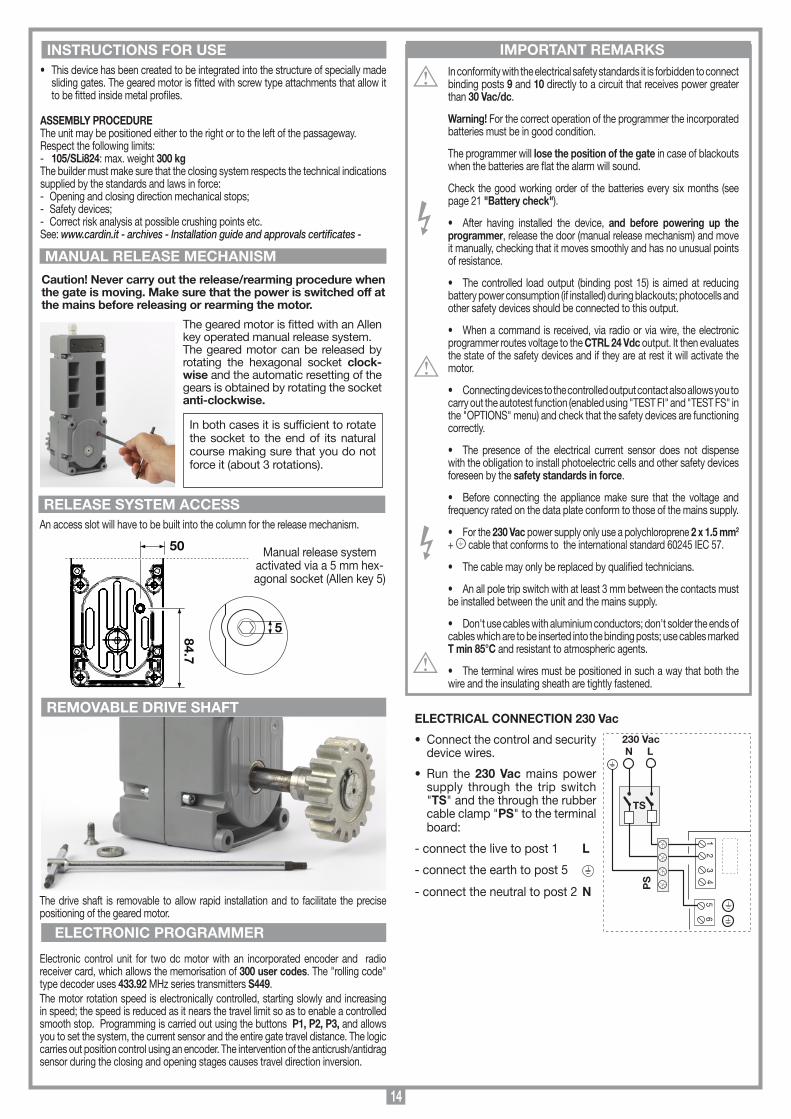
14
In conformity with the electrical safety standards it is forbidden to connect binding posts 9 and 10 directly to a circuit that receives power greater than 30 Vac/dc.
Warning! For the correct operation of the programmer the incorporated batteries must be in good condition.
The programmer will lose the position of the gate in case of blackouts when the batteries are flat the alarm will sound.
Check the good working order of the batteries every six months (see page 21 "Battery check").
• After having installed the device, and before powering up the programmer, release the door (manual release mechanism) and move it manually, checking that it moves smoothly and has no unusual points of resistance.
• The controlled load output (binding post 15) is aimed at reducing battery power consumption (if installed) during blackouts; photocells and other safety devices should be connected to this output.
• When a command is received, via radio or via wire, the electronic programmer routes voltage to the CTRL 24 Vdc output. It then evaluates the state of the safety devices and if they are at rest it will activate the motor.
• Connecting devices to the controlled output contact also allows you to carry out the autotest function (enabled using "TEST FI" and "TEST FS" in the "OPTIONS" menu) and check that the safety devices are functioning correctly.
• The presence of the electrical current sensor does not dispense with the obligation to install photoelectric cells and other safety devices foreseen by the safety standards in force.
• Before connecting the appliance make sure that the voltage and frequency rated on the data plate conform to those of the mains supply.
• For the 230 Vac power supply only use a polychloroprene 2 x 1.5 mm2 + cable that conforms to the international standard 60245 IEC 57.
• The cable may only be replaced by qualified technicians.
• An all pole trip switch with at least 3 mm between the contacts must be installed between the unit and the mains supply.
• Don't use cables with aluminium conductors; don't solder the ends of cables which are to be inserted into the binding posts; use cables marked T min 85°C and resistant to atmospheric agents.
• The terminal wires must be positioned in such a way that both the wire and the insulating sheath are tightly fastened.
ELECTRICAL CONNECTION 230 Vac
• Connect the control and security device wires.
• Run the 230 Vac mains power supply through the trip switch "TS" and the through the rubber cable clamp "PS" to the terminal board:
- connect the live to post 1 L
- connect the earth to post 5
- connect the neutral to post 2 N
REMOVABLE DRIVE SHAFT
MANUAL RELEASE MECHANISM
INSTRUCTIONS FOR USE IMPORTANT REMARKS
ELECTRONIC PROGRAMMER
• This device has been created to be integrated into the structure of specially made sliding gates. The geared motor is fitted with screw type attachments that allow it to be fitted inside metal profiles.
ASSEMBLY PROCEDUREThe unit may be positioned either to the right or to the left of the passageway.Respect the following limits:- 105/SLi824: max. weight 300 kgThe builder must make sure that the closing system respects the technical indications supplied by the standards and laws in force:- Opening and closing direction mechanical stops;- Safety devices;- Correct risk analysis at possible crushing points etc.See: www.cardin.it - archives - Installation guide and approvals certificates -
The drive shaft is removable to allow rapid installation and to facilitate the precise positioning of the geared motor.
Electronic control unit for two dc motor with an incorporated encoder and radio receiver card, which allows the memorisation of 300 user codes. The "rolling code" type decoder uses 433.92 MHz series transmitters S449. The motor rotation speed is electronically controlled, starting slowly and increasing in speed; the speed is reduced as it nears the travel limit so as to enable a controlled smooth stop. Programming is carried out using the buttons P1, P2, P3, and allows you to set the system, the current sensor and the entire gate travel distance. The logic carries out position control using an encoder. The intervention of the anticrush/antidrag sensor during the closing and opening stages causes travel direction inversion.
205/BLi824
17-07-2014
DI0609 Description :
Product Code :
Date:
Drawing number :
P.J.Heath
CARDIN ELETTRONICA S.p.A - 31020 San Vendemiano (TV) Italy - via Raffaello, 36 Tel: 0438/401818 Fax: 0438/401831
Draft :
All rights reserved. Unauthorised copying or use of the information contained in this document is punishable by law
AUTOMAZIONE INTEGRATO PER CANCELLI A BATTENTE
50
84.7
5
Manual release system activated via a 5 mm hex-agonal socket (Allen key 5)
The geared motor is fitted with an Allen key operated manual release system. The geared motor can be released by rotating the hexagonal socket clock-wise and the automatic resetting of the gears is obtained by rotating the socket anti-clockwise.
In both cases it is sufficient to rotate the socket to the end of its natural course making sure that you do not force it (about 3 rotations).
An access slot will have to be built into the column for the release mechanism.
RELEASE SYSTEM ACCESS
65
23
14
230 Vac
TS
N L
PS
Caution! Never carry out the release/rearming procedure when the gate is moving. Make sure that the power is switched off at the mains before releasing or rearming the motor.

15
Terminal board connection1-2 Programmer power supply 230 Vac3-4 Transformer power output 230 Vac5 Programmer power supply earth wire6 Motor earth wire7 TB (N.C./8.2 kΩ) stop button input (The opening of this contact
interrupts the cycle until a new movement command is given).8 CMN common for all inputs and outputs.9 FS (N.C./8.2 kΩ) safety and control devices in input (stop photo-
electric cells). The opening of this contact will block all movement, until the obstruction has been removed, due to the safety device cutting in, the gate will then continue moving until it reaches a travel limit (only in the automatic mode).
10 FI (N.C./8.2 kΩ) safety and control devices in input (photocells invert the travel direction when an obstruction is detected). Opening this contact will provoke a travel direction inversion during closure due to the cutting in of the safety device.
11 CMN common for all inputs and outputs.12 CP (N.C./8.2 kΩ) safety buffer input. Opening this contact will
provoke a travel direction inversion of 5 cm, a pause of 3 minutes, after which the motor will continue moving in the original direction after a 10 second preflashing period has elapsed.
13 LP 24 Vdc output for warning lights. 25 W intermittent activation (50%), 12,5 W continuous activation.
14 CMN common for all inputs and outputs.15 24 Vdc output, powering controlled external loads(1).16 CMN common for all inputs and outputs.17 24 Vdc output, powering permanent external loads(1).18 CMN common for all inputs and outputs.19 TA (NO contact) opening button input.20 TAL (NO contact) limited opening button input.21 TC (NO contact) closing button input.22 TD (NO contact) dynamic button input.23 CMN Common for all inputs and outputs.24 LS 24 Vdc, 3W indicator light output.25 EMRG 1 (NO contact) emergency manoeuvring button input 126 EMRG 2 (NO contact) emergency manoeuvring button input 2
27 Common for both emergency buttons.28 Outer conductor for the radio receiver antenna 29 Inner conductor for the radio receiver antenna (if an external antenna
is fitted use a coaxial type cable RG58 with an impedance of 50Ω).
Note(1) The total of the 2 external device outputs must not exceed 10W.
ALL UNUSED NC CONTACTS MUST BE JUMPED and consequently the security device test must also be deactivated (FI , FS ). If you want to activate the FI, FS test both the transmission and receiver parts of the security devices must be connected to the binding post marked "CTRL 30 Vdc". If the test is active there will be a 1 second delay between the command transmission and movement of the gate.Switch on the power and make sure that the indicator LEDs are indicating the following conditions:- L1 Power on ON- L2 Wrong battery connection OFF (3)
- S1 Indicator for the blocking button "TB" ON (4)
- S2 Indicator for the inverting photoelectric cells "FI" ON (4)
- S3 Indicator for the stop photoelectric cells "FS" ON (4)
- S4 Indicator for the safety edge "CP" ON (4)
- S5 Indicator for the opening button (TA) OFF- S6 Indicator for the closing button (TC) OFF- S7 Indicator for the limited opening button (TAL) OFF- S8 Indicator for the sequential command (TD/CH1) OFF
Note(3) If this LED is "ON" invert the battery power cables immediately.Note(4) These indications are "ON" if the relative security devices are inactive.
Check that the activation of the safety devices makes the correspond-ing indicator lights flash. A fleshing LED indicates an alarm status.
If the green power on LED "L1" doesn't light up check the condition of the fuses and the power cable connection at the transformer primary. If one or more of the safety LEDs "S1, S2, S3, S4" flash check the contacts of the relative security devices and check that the unused safety device contacts have been bridged. The indications "S5, S6, S7, S8" appear on the display when the relative command is activated, eg. pressing the button "TA" will force "TA" to appear on the display.
Collegamenti scheda base
CC824
16-07-2014
DC0547 Description :
Product Code :
Date :
Drawing number :
P.J.Heath
CARDIN ELETTRONICA S.p.A - 31020 San Vendemiano (TV) Italy - via Raffaello, 36 Tel: 0438/401818 Fax: 0438/401831
Draft :
All rights reserved. Unauthorised copying or use of the information contained in this document is punishable by law
CC824 SCHEDA BASE(con display LCD + manovra di emergenza)
CS1412B DC0546
M1
R1
B1
F3 10 A
F2 10 A
2829
TRANSFORMER
23
14
65
TRF 230Vac
230VacL
N
1211109 18171615141387
22212019 2423
TA TDTC CM
N
TB
CM
N
FS FI LP
CM
N
CM
N
OUT24Vdc
L1LS
25 26 27
CM
N
EM
RG
2
EM
RG
1
TAL
F4 3.15 A
BC
F1 3.15 A
CTRLOUT
24Vdc
CM
N
CM
N
CP
Enable
Disable
LCD1
T B
F S
F I
C P
S1
S3
S2
S4
P1 P2 P3
PROG/OK
L2
J1
J2
J3
YwBlGrGrENCODER
MOTOR
B1 Signal buzzer "via radio" mode BC Battery charger card LCD1 DisplayF1 3.1 A rapid fuse (24V battery powered operation protection)F2 10 A rapid fuse (battery powered operation motor protection) F3 10 A rapid fuse (motor power protection from transformer) F4 3.1 A rapid fuse (24V transformer power protection )
J1 Battery connectionJ2 Transformer secondary connectionJ3 Emergency enable jumper M1 Transmitter code memory moduleP1 Menu navigation button ( )P2 Programming and confirm button (PROG./OK) P3 Menu navigation button ( )R1 Radio frequency module, 433 MHz for S449 transmitters
10

16
Value Torque at Torque at slow speed top speed 1 25% 75% 2 25% 100% 3 36% 75%
Value Torque at Torque at slow speed top speed 4 36% 100% 5 60% 75% 6 60% 100%
Press the arrows to increase or reduce the value (max 240 seconds).Keep the arrow keys pressed to scroll the value rapidly.
Press OK to reset the parameters to the factory default settings (excluding thenumber of manouvres). Press EXIT to quit without modifying the parameters
“PROG/OK” to confirm
BACK TO MOTION MENU
EXIT
OK
“PROG/OK” to set
RESET PARAMETERS
OK
“PROG/OK” to set
DIST. FROM OPEN (6)
0...9 steps
“PROG/OK” to set
DIST. FROM CLOSE (6)
0...9 steps
SEQUENTIAL COM. OPEN-SHUT/
OPEN-STOP-SHUT“PROG/OK” to set
AUTO-RECLOSING
ON/OFF“PROG/OK” to set
“PROG/OK” to set
WARNING LIGHTSFIXED/
INTERMITTENT“PROG/OK” to set
INDICATOR LIGHT (1)
FIXED/INTERMITTENT“PROG/OK” to set
PHOTOCELL INVERT (2)
DURING CLOSING/AND IN STOP
“PROG/OK” to set
“PROG/OK” to set
“PROG/OK” to set
INSTALLED MOTOR LEFT/RIGHT
“PROG/OK” to set
“PROG/OK” to set
“PROG/OK” to confirm
BACK TO OPTIONS
PRE-FLASHING
ON/OFF
TEST FI (3)
ON/OFF
TEST FS (3)
ON/OFF
MEMO RADIO
ON/OFF
EXIT
OK
“PROG/OK” to set
FI CONTACT
NC/8K2
TB CONTACT
NC/8K2
“PROG/OK” to set
“PROG/OK” to set
“PROG/OK” to set
“PROG/OK” to confirm
BACK TO SAFETY DEVICES
FS CONTACT
NC/8K2
CP CONTACT
NC/8K2
EXIT
OK
“PROG/OK” to set
CURRENT SENSOR (5)
LEVELS 1...5“PROG/OK” to set
“PROG/OK” to set
LIMITED OPENING
1...9 meters
“PROG/OK” to set
ADJUST CONTRAST
0...63
CONTRAST
OK
“PROG/OK” to confirm “PROG/OK” to confirm
SAFETY DEVICES
OK
“PROG/OK” to confirm
CANCELLATION
OK
MEMORISE
OK
“PROG/OK” to confirm
“PROG/OK” to confirm
“PROG/OK” to confirm
“PROG/OK” to confirm
BACK TO RADIO CODES MENU
CLEAR ALL MEMORY
OK
CHANNEL FUNCTION
OK
EXIT
OK
“PROG/OK” to confirm
REMOTE
OK
OPTIONS
OK“PROG/OK” to confirm
MOTION
OK
PRESS ANY KEY
BACK TO TEST MENU
“PROG/OK” to confirm
TEST
OK“PROG/OK” to confirm
DISPLAY
OK
“PROG/OK” to confirm
“PROG/OK” to set
“PROG/OK” to confirm
BACK TO DISPLAY MENU
EXIT
OK
REAR LIGHTINGALWAYS ON/
60 SEC./30 SEC.
TORQUE SELECTION (4)
LEVELS 1...6
PROGRAMT BF S
F IC P
00.000.001T BF S
F IC P
TESTT BF S
F IC P
PRESS the transmitter
channel to be memorised
CANCELLING.....
MEMORISE [nr ...]
Activation 1
PRESS the transmitter
channel to be memorised
MEMORISE [nr ...]
Activation 2
MEMORISE [nr ...]
CODE MEMORISED
“PROG/OK” to confIrm
CLEAR ALL MEMORY?
OK
PRESS the transmitter
channel to be cancelled
CANCEL [nr ...]
Activation 1
PRESS the transmitter
channel to be cancelled
CANCEL [nr ...]
Activation 2
CANCEL [nr ...]
CODE CANCELLED
Exit
“PROG/OK” to set
CHANNEL ACOMMAND TD/TAL/TA/TC/
STOP/NO COMMAND
CHANNEL BCOMMAND TD/TAL/TA/TC/
STOP/ NO COMMAND
“PROG/OK” to set “PROG/OK” to set
CHANNEL CCOMMAND TD/TAL/TA/TC/
STOP/ NO COMMAND
“PROG/OK” to set
CHANNEL DCOMMAND TD/TAL/TA/TC/
STOP/ NO COMMAND
“PROG/OK” to set
BACK TO CHANNEL FUNCTION MENU
EXIT
OK
OUT OF POST BF S
F ICP
STOP PROGT BF S
F ICP
PROGRAMT BF S
F ICP Flashing on the display. You have to enter the programming mode to program the system.
During normal operation it indicates that the "automatic repositioning" procedure is about to take place. In this case any commands received (TA, TC, TAL or TD) will automatically start this procedure.
This happens when an N.C. contact is activated (FI, FS, CP) during encoder programming or automatic repositioning. Once the passive state of the security devices has been reset the gate will start moving again automatically. It also happens if a blackout occurs during programming.
Safety device test error. Check the condition of the safety devices and make sure that the alarm cuts in when an obstacle interferes with the beam (the relative LED will switch off). In case of anomalies replace the damaged safety device or bridge the contact and deactivate the safety test (option menu).
This occurs when the programmer sends a command to the motor and nothing happens (the motor doesn't move). Check the motor faston connections and the condition of the fuses "F2", "F3" and then give another opening or closing command. If the motor still doesn't move you are faced with either a mechanical problem or a problem with the programmer.
If this error occurs during normal motor operation it means that there is a problem with one of the encoder signals. Check the relative connections and carry out automatic repositioning.
The gate movement direction is different from the encoder setting (eg. the gate moves in the closing direction while the program is carrying out the opening stage). Check the motor power supply connections.
Current sensor error. When the gate is not moving this symbol means there is a problem with the current sensor.
When the safety edge intervenes the gate will automatically invert for 5 cm, both in the closing as well as the opening direction, to free the obstacle it will then stop for 3 minutes and then continue moving in the original direction after a 10 second preashing period has elapsed.
When the sensor intervenes the gate will automatically invert for 5 cm, both in the closing as well as the opening direction, to free the obstacle it will then stop for 3 minutes and then continue moving in the original direction after a 10 second preashing period has elapsed.
SAFETY ERRT BF S
F ICP
ERROR MOT1T BF S
F ICP
ERROR ENC1T BF S
F ICP
ERROR DIR1T BF S
F ICP
ERR. SENS1T BF S
ICP
ACT. EDGET BF S
ICP
ACT. SENST BF S
ICP
Alarm indications
AUTO PROGT BF S
F ICP
OPENINGT BF S
F ICP
PAUSET BF S
F ICP
Pause time programming or pause for automatic reclosing (if activated)
Automatic programming under way
Opening stage
Block during opening
Closing stage
Block during closing
Current sensor updating (only during programming)
Test mode
Battery mode with a fully charged battery
Battery mode with a discharged battery. The motor and commands will be blocked.
STOP OPENT BF S
F ICP
UPDAT.SNS1T BF S
F ICP
TESTT BF S
ICP
BATT. [99%]T BF S
ICP
Operational indications
CLOSINGT BF S
F ICP
STOP CLOSET BF S
F ICP
BATT. [0%]T BF S
ICP
AUTO PROG
F
F
F F
F
F
“PROG/OK” to set
PAUSE TIME: 30
OK
FW_0.11
5) Current sensor settings:- Level 1 = motor electrical input + 2 amps - Level 2 = motor electrical input + 2.5 amps- Level 3 = motor electrical input + 3 amps - Level 4 = motor electrical input + 4 amps - Level 5 = motor electrical input + 5 ampsThe programmer checks the electrical input to the motor, detecting any eventual increase in effort above the normal operating limits and intervenes as an additional safety device. 6) Setting the distance from the closing/opening travel limit: To increase or reduce this distance modify the parameter in steps from 0 to 9 (range fro 0 to 6 cm ~). By default the appliance is set to level 4 and in this
way the gate will not slam against the travel limits but will stop within a centimetre of them.
PROGRAMMING PROCEDURE (parameter setting)
• All the functions of the electronic programmer can be set in the Display menu "LCD1" using the three buttons contained therein:- use the arrows to navigate through the menu and/or to adjust the display contrast;- use "PROG/OK" to modify the parameter settings and/or to confirm.
Note:1) The indicator light flashes slowly during opening, rapidly during closing; remains lit when
the gate is blocked but not completely closed and is off when the gate is completely closed.2) FI Mode:- FI also active when the gate is blocked: If the photocells are in alarm and the gate is blocked, no
movement commands will be accepted (even opening commands);- FI active only during closing In both cases activating the FI safety device during the closing stage will force travel direction
inversion.3) Photocell test (FI/FS) If you enable the security test you will have to connect both the transmitter and the receiver to the
controlled load output (CTRL 24 Vdc). When the test is enabled one second will pass between receiving a command and carrying it out.
4)

17
Press the arrows to increase or reduce the value (max 240 seconds).Keep the arrow keys pressed to scroll the value rapidly.
Press OK to reset the parameters to the factory default settings (excluding thenumber of manouvres). Press EXIT to quit without modifying the parameters
“PROG/OK” to confirm
BACK TO MOTION MENU
EXIT
OK
“PROG/OK” to set
RESET PARAMETERS
OK
“PROG/OK” to set
DIST. FROM OPEN (6)
0...9 steps
“PROG/OK” to set
DIST. FROM CLOSE (6)
0...9 steps
SEQUENTIAL COM. OPEN-SHUT/
OPEN-STOP-SHUT“PROG/OK” to set
AUTO-RECLOSING
ON/OFF“PROG/OK” to set
“PROG/OK” to set
WARNING LIGHTSFIXED/
INTERMITTENT“PROG/OK” to set
INDICATOR LIGHT (1)
FIXED/INTERMITTENT“PROG/OK” to set
PHOTOCELL INVERT (2)
DURING CLOSING/AND IN STOP
“PROG/OK” to set
“PROG/OK” to set
“PROG/OK” to set
INSTALLED MOTOR LEFT/RIGHT
“PROG/OK” to set
“PROG/OK” to set
“PROG/OK” to confirm
BACK TO OPTIONS
PRE-FLASHING
ON/OFF
TEST FI (3)
ON/OFF
TEST FS (3)
ON/OFF
MEMO RADIO
ON/OFF
EXIT
OK
“PROG/OK” to set
FI CONTACT
NC/8K2
TB CONTACT
NC/8K2
“PROG/OK” to set
“PROG/OK” to set
“PROG/OK” to set
“PROG/OK” to confirm
BACK TO SAFETY DEVICES
FS CONTACT
NC/8K2
CP CONTACT
NC/8K2
EXIT
OK
“PROG/OK” to set
CURRENT SENSOR (5)
LEVELS 1...5“PROG/OK” to set
“PROG/OK” to set
LIMITED OPENING
1...9 meters
“PROG/OK” to set
ADJUST CONTRAST
0...63
CONTRAST
OK
“PROG/OK” to confirm “PROG/OK” to confirm
SAFETY DEVICES
OK
“PROG/OK” to confirm
CANCELLATION
OK
MEMORISE
OK
“PROG/OK” to confirm
“PROG/OK” to confirm
“PROG/OK” to confirm
“PROG/OK” to confirm
BACK TO RADIO CODES MENU
CLEAR ALL MEMORY
OK
CHANNEL FUNCTION
OK
EXIT
OK
“PROG/OK” to confirm
REMOTE
OK
OPTIONS
OK“PROG/OK” to confirm
MOTION
OK
PRESS ANY KEY
BACK TO TEST MENU
“PROG/OK” to confirm
TEST
OK“PROG/OK” to confirm
DISPLAY
OK
“PROG/OK” to confirm
“PROG/OK” to set
“PROG/OK” to confirm
BACK TO DISPLAY MENU
EXIT
OK
REAR LIGHTINGALWAYS ON/
60 SEC./30 SEC.
TORQUE SELECTION (4)
LEVELS 1...6
PROGRAMT BF S
F IC P
00.000.001T BF S
F IC P
TESTT BF S
F IC P
PRESS the transmitter
channel to be memorised
CANCELLING.....
MEMORISE [nr ...]
Activation 1
PRESS the transmitter
channel to be memorised
MEMORISE [nr ...]
Activation 2
MEMORISE [nr ...]
CODE MEMORISED
“PROG/OK” to confIrm
CLEAR ALL MEMORY?
OK
PRESS the transmitter
channel to be cancelled
CANCEL [nr ...]
Activation 1
PRESS the transmitter
channel to be cancelled
CANCEL [nr ...]
Activation 2
CANCEL [nr ...]
CODE CANCELLED
Exit
“PROG/OK” to set
CHANNEL ACOMMAND TD/TAL/TA/TC/
STOP/NO COMMAND
CHANNEL BCOMMAND TD/TAL/TA/TC/
STOP/ NO COMMAND
“PROG/OK” to set “PROG/OK” to set
CHANNEL CCOMMAND TD/TAL/TA/TC/
STOP/ NO COMMAND
“PROG/OK” to set
CHANNEL DCOMMAND TD/TAL/TA/TC/
STOP/ NO COMMAND
“PROG/OK” to set
BACK TO CHANNEL FUNCTION MENU
EXIT
OK
OUT OF POST BF S
F ICP
STOP PROGT BF S
F ICP
PROGRAMT BF S
F ICP Flashing on the display. You have to enter the programming mode to program the system.
During normal operation it indicates that the "automatic repositioning" procedure is about to take place. In this case any commands received (TA, TC, TAL or TD) will automatically start this procedure.
This happens when an N.C. contact is activated (FI, FS, CP) during encoder programming or automatic repositioning. Once the passive state of the security devices has been reset the gate will start moving again automatically. It also happens if a blackout occurs during programming.
Safety device test error. Check the condition of the safety devices and make sure that the alarm cuts in when an obstacle interferes with the beam (the relative LED will switch off). In case of anomalies replace the damaged safety device or bridge the contact and deactivate the safety test (option menu).
This occurs when the programmer sends a command to the motor and nothing happens (the motor doesn't move). Check the motor faston connections and the condition of the fuses "F2", "F3" and then give another opening or closing command. If the motor still doesn't move you are faced with either a mechanical problem or a problem with the programmer.
If this error occurs during normal motor operation it means that there is a problem with one of the encoder signals. Check the relative connections and carry out automatic repositioning.
The gate movement direction is different from the encoder setting (eg. the gate moves in the closing direction while the program is carrying out the opening stage). Check the motor power supply connections.
Current sensor error. When the gate is not moving this symbol means there is a problem with the current sensor.
When the safety edge intervenes the gate will automatically invert for 5 cm, both in the closing as well as the opening direction, to free the obstacle it will then stop for 3 minutes and then continue moving in the original direction after a 10 second preashing period has elapsed.
When the sensor intervenes the gate will automatically invert for 5 cm, both in the closing as well as the opening direction, to free the obstacle it will then stop for 3 minutes and then continue moving in the original direction after a 10 second preashing period has elapsed.
SAFETY ERRT BF S
F ICP
ERROR MOT1T BF S
F ICP
ERROR ENC1T BF S
F ICP
ERROR DIR1T BF S
F ICP
ERR. SENS1T BF S
ICP
ACT. EDGET BF S
ICP
ACT. SENST BF S
ICP
Alarm indications
AUTO PROGT BF S
F ICP
OPENINGT BF S
F ICP
PAUSET BF S
F ICP
Pause time programming or pause for automatic reclosing (if activated)
Automatic programming under way
Opening stage
Block during opening
Closing stage
Block during closing
Current sensor updating (only during programming)
Test mode
Battery mode with a fully charged battery
Battery mode with a discharged battery. The motor and commands will be blocked.
STOP OPENT BF S
F ICP
UPDAT.SNS1T BF S
F ICP
TESTT BF S
ICP
BATT. [99%]T BF S
ICP
Operational indications
CLOSINGT BF S
F ICP
STOP CLOSET BF S
F ICP
BATT. [0%]T BF S
ICP
AUTO PROG
F
F
F F
F
F
“PROG/OK” to set
PAUSE TIME: 30
OK
FW_0.11
• Set the main operating parameters (e.g. installation right/left) in the options menu.• If you have safety devices working with 8.2k contacts select the correct setting from the safety device menu.• Before programming the gate travel distances select the correct motor in the "Motion" menu.
Language choice:
• Press the right and left buttons simultaneously to enter the language submenu.
• Press the right and left buttons to change the language: Italian to French.
• Press the "PROG/OK" button to confirm the choice.“PROG/OK” to confirm
ENGLISH
OK
Press the right and left buttons simltaneously to enter the
language submenu
PROGRAMT BF S
F IC P

18
PROGRAMMING PROCEDURE(gate travel distance and current sensor)
Memory module (M1)This is extractable, furnished with a non volatile EEPROM type memory and contains the transmitter codes and allows you to memorise up to 300 codes. The programmed codes are maintained in this module even during blackouts. Before memorising the transmitters for the first time remember to cancel the entire memory content.If the electronic card has to be replaced due to failure, the module can be extracted from it and inserted into the new card. Make sure that the module is correctly inserted as shown in fig. 3.
TRANSMITTER CODE MANAGEMENT
Memorising a channel1. Scroll to the "MEMORISATION" step in the "REMOTE" menu and confirm using
the "PROG/OK" button: the indication "Activation 1" will flash on the LCD.2. Activate the transmitter channel that is to be memorised: the indication "Activation 2" will flash on the LCD.3. Activate the transmitter again (same transmitter, same channel*): the indication "Code memorised" will flash on the LCD.The number of channels already present in the memory is shown on the first line in brackets.* if the channel is different or it is a different transmitter (point three) the memorisation attempt will abort without success however "Activation 1" will still flash on the LCD.
Note: It is not possible to memorise a code which is already in memory: if you attempt this the indication "COD. IN MEM." (point one) will appear on the LCD.
Cancelling a channel:1. Scroll to the "CANCELLATION" step in the "REMOTE" menu and confirm using
the "PROG/OK" button: the indication "Activation 1" will flash on the LCD.2. Activate the transmitter channel that is to be cancelled: the indication "Activation 2" will flash on the LCD.3. Activate the transmitter again (same transmitter, same channel*): the indication "Code cancelled" will flash on the LCD.The number of channels already present in the memory is shown on the first line in brackets.* if the channel is different or it is a different transmitter (point three) the cancellation attempt will abort without success however "Activation 1" will still flash on the LCD.
Note: It is not possible to cancel a code which is not already in memory: if you attempt this the indication "COD. NOT MEM." (point one) will appear on the LCD.
Cancelling all user codes from memory:1. Scroll to the "CANCEL ALL MEMORY" step in the "REMOTE" menu and con-
firm using the "PROG/OK" button: a procedure confirmation request "CANC ALL MEMORY?" will appear on the LCD (press one of the arrows to exit the procedure).
2. Press the "PROG/OK" button to confirm the total cancellation: the indication "CANCELLING" along with a progress bar will appear on the
display.3. Once the total cancellation has been carried out the display will return to "CANCEL
ALL MEMORY".
Memorising ulterior channels via radio • The system can be remotely activated using radio control devices; (without opening
the receiver) by setting "MEMO RADIO" has been activated in the "OPTIONS" menu.
1. Using a transmitter, in which at least one channel button "A, B, C or D" has already been memorised in the receiver, press the button in the transmitter as shown in figure.
Note: all the receivers within range when the channel button is pressed (and which have at least one of the transmitter channel buttons memorised) will activate their signal buzzer "B1" (fig. 3).2. Press one of the channel buttons on the same transmitter. The receivers which do
not contain that channel code will sound a five-second long "beep" and will then deactivate. The receivers which contain the channel code will sound a one-second long "beep" and will enter the "programming via radio" mode.
3. Press the previously chosen channel buttons on the transmitter which you wish to memorise; the receiver will sound 2 "beeps" of half a second each after which the receiver will be ready to receive another code.
4. To leave the programming mode wait for 3 seconds without pressing any buttons. The receiver will sound a five-second long "beep" and will then exit the program-ming mode.
Note: When the memory is entirely occupied the buzzer will sound 10 rapid "beeps" and will automatically leave the "programming via radio" mode.The same signal is given each time you try to enter "programming via radio" when the memory is full.Note: the memo radio procedure can only be carried out after programming has terminated and you have quit the setting/programming menu.
• The installation of anti-derailment buffers is absolutely obligatory.• Make sure the safety devices are at rest and the ECU is receiving mains power
otherwise you will not be able to enter programming. • It is not possible to enter programming when working off battery power.• Before programming set the main operating parameters in the "OPTIONS"
menu.
REPOSITIONING
Attention! During the repositioning manoeuvre the current sensor value could be altered. At the end of the manoeuvre, however, it will reset automatically to the chosen value.
If the programmer blocks due to an encoder count error ("Error ENC" on the dis-play), after a programmer reset ("Out of pos.") or when there is a problem with the motor ("Mot error") the warning lights and indicator light will flash simultaneously for 2 seconds and will then switch off for 10 seconds. If in this stage you send a (TA, TC, TAL or TD) command to the programmer.The programmer will move the gates slowly to the completely closed position (2 times as in the programming procedure) in order to recover the correct position.At this point the programmer will function normally. If a "TA" command is given the positioning recovery is carried out in the opening direction.No commands will be accepted during repositioning but the security devices will cut in and block all movement if they go into alarm.To interrupt the repositioning manoeuvre press the "PROG" or "TB" button.
The system can be remotely activated using radio control devices; each channel has a choice of 6 possible functions: open - shut - limited opening - sequential command - stop.To set the functions to channels "A","B","C","D" use the command "CHANNEL FUNCTIONS" from the "REMOTE" menu. The sequential command may be set to "open-stop-shut-stop" or "open-close".
REMOTE CONTROL
1...4... sec.
The pause time count will start (min. 2 seconds: max. 120 seconds) indicated by "PAUSE" and the elapsed time appearing on the display
Press “PROG” to set the pause time to the required value. The door will now open slowly in order to find the completely open position.
When the gate reaches the completely open travel limit it will invert the travel direction and after moving a few centimetres it will open again to confirm the completely open position. At this point the gate will start to close. When the gate reaches the completely closed travel limit it will invert the travel direction and after moving a few centimetres it will close again to confirm the completely open position.
After having carried out this manoeuvre the logic control will open then close the gate completely in order to calibrate the current sensor.
When the gate reaches the completely closed position the programmer saves the parameters and quits the programming mode.
The operation has not succeeded. You will have to repeat the programming procedure.
Press and hold down prog/ok for 4 seconds
“PROG/OK” for 4 sec.
“PROG/OK”
“PROG/OK”
PROGRAMT BF S
F IC P
T BF S
F IC P
PROGRAMT BF S
F IC P
PAUSE
AUTO PROG.
PAUSE 005
AUTO PROG.
T BF S
F IC P
OPENING
AUTO PROG.
AUTO-PROGRAMMINGCYCLE
T BF S
F IC P
CLOSING
AUTO PROG.
T BF S
F IC P
T BF S
F IC P
MEMORIZZAZIONE CODICE TX-RX
RCQ449100
13-04-2001
DM0531 Description :
Product Code :
Date :
Drawing number :
P.J.Heath
CARDIN ELETTRONICA S.p.A - 31020 San Vendemiano (TV) Italy - via Raffaello, 36 Tel: 0438/401818 Fax: 0438/401831
Draft :
All rights reserved. Unauthorised copying or use of the information contained in this document is punishable by law
MR

19
CONNECTING THE ANTENNA Connect an ANS400 tuned antenna using a coaxial cable RG58 (impedance 50Ω) with a maximum length of 15 m.
1) AutomaticSelected by enabling automatic reclosing (Automatic reclosing "ON" on the display). When the door is completely closed the opening command will start a complete cycle which will end with automatic reclosing. Automatic reclosing starts after the programmed pause period has elapsed (minimum 2 seconds) when the opening cycle has been completed or straight away after the intervention of a photoelectric cell (the intervention of a photoelectric cell causes the pause time to be reset). During the pause time "Pause" will flash on the display along with the remaining pause time.pressing the blocking button during this period will stop automatic reclosing and consequently stop the display from flashing. The indicator light remains lit until the closing manoeuvre has terminated.
2) SemiautomaticSelected by deactivating automatic reclosing (Automatic reclosing "OFF" on the display). Work cycle control using separate opening and closing commands. When the door has reached the completely open position the system will wait until it receives a closing command either via an external control button or via radio control, before completing the cycle. The indicator light remains lit until the closing manoeuvre has terminated.
3) Manual manoeuvring with released motorsReleasing the motor the gate can be moved by hand; once the motor has been re-engaged the programmer will recover the position after two consecutive attempts to arrive at the travel limit.
4) Emergency manoeuvreBy default the emergency manoeuvre is disabled, to enable it move the jumper to the position J3 "ENABLE" (fig. 2). If the electronic programmer no longer responds to commands due to a malfunction you may use the EMRG1 or EMRG2 inputs to move the gate leaf manually (fig. 2). The EMRG1 or EMRG2 inputs directly com-mand the motor without passing through the logic control.
Gate movement will be at normal speed and the direction depends on the installed position of the motor:- left-hand installed motor EMRG1 closes and EMRG2 opens;- right-hand installed motor EMRG1 opens and EMRG2 closes.
Attention! During the emergency manoeuvre all safety devices are disabled and there is no gate positioning control: release the commands before you are at the mechanical travel buffer. Only use the emergency manoeuvre in cases of extreme necessity.
After you have carried out an emergency manoeuvre the electronic programmer will lose the position of the gate ("out of pos" on the display) and therefore when normal operation is restored it will carry out a repositioning manoeuvre.
• If the "open-close" mode is set for the "TD" button (menu "OPTION") activating the "TAL" button will start the limited opening stage (only from the completely closed position) but while the gate is opening pressing the button again will have no effect. Once the opening position has been reached pressing the "TAL" button will start closing after which pressing "TAL" again will have no effect.
• If the "open-block-close" mode is set for the "TD" button (menu "OPTION") activating the "TAL" button will start the limited opening stage (only from the completely closed position) pressing the button again will block the gate; press-ing the button a third time will start the closing cycle. Pressing the "TAL" button again will have no effect.
• If an opening command is received during limited opening; the limited opening command will become a full opening command.
If the FI photocell cuts in during the closing stage you will only have partial movement in the opening direction (It reopens only for the distance it has been closing the gate).
• Note: The limited opening command can also be given using the second channel radio function.
The limited opening distance is set to half of the entire opening distance.
This device allows the propulsion unit to work during blackouts.
• The programmer has a built in charger for an NiMH 24V battery that is managed by a dedicated micro controller. The control chip adjusts the voltage according to the condition of the connected battery.
To avoid the risk of overheating only use the battery supplied by the manufacturer SPN 999540.If the battery shows signs of damage it must be replaced immediately.The battery must only be installed/removed by qualified personnel. Used batteries must not be thrown into domestic rubbish bins and they must be disposed of according to the local standards and regulations in force.
• The unit returns to normal operation once the power supply brought back on line. To use the battery again it must first be allowed to recharge.
The battery charge time with a battery in good condition can take up to a maxi-mum of 16 hours. If the time required is greater you should consider replacing the battery. You are however advised to replace the battery every three years.
• When the door has stopped, the controlled external devices (CTRL 24 Vdc) do not receive power in order to increase the autonomy of the battery. When a command is received however (via radio or via cable) the programmer sends power to the controlled external devices and checks their security status. It follows therefore that the command will be carried out (security devices at rest) with a one second delay to give time to restore the correct operation of the devices. If after this period a security device is found to be in alarm the command will not be carried out, power to the external devices will be cut off and the programmer will return to stand-by.
Note! If you wish to use an external receiver it must be wired to the binding posts 16-17 (fig. 3) otherwise a command sent via radio will not be able to activate the door.
• The self-sufficiency of the system when it is running on battery power is depend-ent on the ambient conditions and on the load connected at binding posts 16-17 (power is always routed there during blackouts).
When the battery is completely flat (during blackouts) the programmer will lose the position of the door and therefore when power returns (after the first command given) you will have to carry out the repositioning procedure (see page 21). For this reason you should avoid leaving the electronic programmer without power for lengthy periods (more than two days).
• It is not possible to enter the programming mode when running off battery power.
• During blackouts the battery supplies power to both the logic and the motor control parts of the programmer.
For this reason during battery powered operation the voltage applied to the motor is inferior to the voltage supplied during normal operation and the motor will therefore work slower and will not decelerate when approaching the travel limits.
Slot-in battery charger
The LED L3 indicates the function mode as follows: Off: missing batteries or the electronic programmer is running
off battery power (during a blackout). During the first 10 seconds of operation from the start up of the electronic programmer the battery charger is blocked. After this period has elapsed it may either start self-diagnostics (indicated by a lengthy flashing of the Led) or it will start recharging (Led continuously lit);
Brief flashing: voltage variation has been detected at the battery charger binding posts (e.g. when the batteries are being connected or removed);
Single flashing: this repeats every 2 seconds indicating that the batteries are being topped up to maintain their level;
Remains lit: the batteries are charging. The charge time depends on a number of factors and can last up to 16 hours. Using the motor will increase the time needed for charging.
Battery checkWith the gate in the completely closed position and the display switched off. Check that LED "L3" (battery charging) is giving off "one flash at a time".Switch off the power at the mains and make sure that the display indicates that it is working off battery power and that the charge is greater than 90%. Give a movement command and measure the overall voltage : The reading should be at least 22 Vdc.
LIMITED OPENING (PEDESTRIAN ACCESS)
BATTERY POWERED OPERATION
FUNCTION MODES
CS
1256
BD
C04
50L3
Scheda di innesto
PRG424BC
08-01-2008
DC0435 Description :
Product Code :
Date :
Drawing number :
P.J.Heath
CARDIN ELETTRONICA S.p.A - 31020 San Vendemiano (TV) Italy - via Raffaello, 36 Tel: 0438/401818 Fax: 0438/401831
Draft :
All rights reserved. Unauthorised copying or use of the information contained in this document is punishable by law
Scheda carica batteria

20
NOTES

21
LES SYSTÈMES INTÉGRABLES CARDIN SONT CONÇUS ET CONSTRUITS POUR ÊTRE UTILISÉS EXCLUSIVEMENT SUR STRUCTURES MÉTALLIQUES EXPRESSÉMENT PRÉVUES À CET EFFET. CARDIN ELETTRONICA NE DONNE AUCUNE GARANTIE POUR DES PRODUITS QUI NE SONT PAS INSTALLÉS
6) Il est conseillé de signaler l'automatisation du portail par des panneaux de signalisation (comme celui indiqué en figure) placés bien en vue. Dans l'hypothèse où l'automatisme serait affecté exclusivement au passage de véhicules, il faudra prévoir deux panneaux d'interdiction de passage aux piétons (l'un à l'intérieur et l'autre à l'extérieur).
7) Il est impératif de poser, en amont de l’automatisme, un disjoncteur qui garantit une déconnexion omnipolaire de la ligne d’alimentation. Ce dispositif doit avoir une ouverture des contacts telle à permettre une déconnexion complète en cas de surtension (catégorie III), conformément aux règles d’installation nationales.
8) Pour garantir la sécurité électrique, il est impératif de brancher l’appareil à la prise de terre.9) En cas d'un quelconque doute sur la sécurité de l'installation, interrompre la pose et
contacter le distributeur du matériel.
DESCRIPTION TECHNIQUE• Le kit comprend:1 motoréducteur autobloquant 100/SLi824 avec encodeur intégré sans électronique à
bord.1 programmateur électronique CC824 avec batteries NiMH, chargeur de batterie et module
radio S449 intégrés.• Le motoréducteur est alimenté avec une tension maxi. 24 Vdc. Au sein de celui-ci intervient
un système cinématique à double réduction qui opère sous bain de graisse fluide . • Le motoréducteur est équipé d’un système de déverrouillage à câble pour l’activation
de la réversibilité du réducteur épicycloïdal.• Le branchement entre motoréducteur et armoire de commande s’effectue par l’intermé-
diaire d’un câble blindé particulier à 7 pôles à connexions rapides. Programmateur pour la commande de un moteur pour portails coulissants avec
motorisation 24 Vdc avec encodeur permettant le contrôle précis de la position du vantail. Le repositionnement du portail intervient en automatique si des évènements non liés au fonctionnement surviennent sur sa course. En cas de déverrouillage manuel, le capteur placé sur le système mécanique impose à la centrale de lancer automatiquement le repositionnement à la première commande de manœuvre qui est délivrée. Le contrôle effectué par le programmateur se complète par la gestion des fonctions de sécurité anti-coincement et des fonctions de régulation du mouvement "soft start" et "soft stop". Logé sous boîtier en matière plastique antichoc IP55, l’appareil électronique est équipé de série d’un chargeur de batterie enfichable et de batteries de secours NiMH utiles pour les manœuvres d’urgence, d’un module radio pour la commande à distance et d’un afficheur LCD (2 lignes de 16 digits) permettant la visualisation de toutes les fonctions activées et du nombre de manœuvres effectuées par l’automatisme, ainsi que la configuration rapide des paramètres et des modes de fonctionnement.
Attention! Marquage WEEE. Ce symbole indique l’obligation de ne pas éliminer l’appareil, à la fin de sa durée de vie, avec les déchets municipaux non triés et de procéder à sa collecte sélective. Par conséquent, l’utilisateur doit remettre l’appareil à
un centre de collecte sélective des déchets électroniques et électriques ou au revendeur qui est tenu, lorsqu’il fournit un nouvel appareil, de faire en sorte que les déchets puissent lui être remis, sur une base de un pour un, pour autant que l’appareil soit de type équivalent à celui qu’il fournit. La collecte sélective des équipements électriques et électroniques en vue de leur valorisation, leur traitement et leur élimination dans le respect de
l’environnement contribue à éviter la nocivité desdits équipements pour l’environnement et pour la santé et à encourager leur recyclage. L’élimination abusive de l’équipement de la part du détenteur final comporte l’application des sanctions administratives prévues par les normes en vigueur dans l’État Membre d’appartenance.
Durant la manœuvre, contrôler le mouvement du portail et actionner, en cas de danger, le dispositif d'arrêt d'urgence (STOP).
En cas d’urgence, le portail peut être déverrouillé manuellement au moyen de la clé de déverrouillage expressément conçue à cet effet et fournie en dotation (voir déverrouillage manuel à la page 22).
Il est conseillé de graisser toutes les parties mobiles avec un lubrifiant qui maintient au fil des années ses qualités lubrifiantes et qui est adapté à des températures oscillant entre -20° et +70°C.
En cas de panne ou de mauvais fonctionnement, mettre l'appareil immédiatement hors tension et contacter le service d'assistance technique.
Contrôler régulièrement le fonctionnement des dispositifs de sécurité (cellules photoélec-triques, etc...).
Les éventuelles réparations devront être effectuées par un personnel spécialisé qui devra prendre soin de monter exclusivement des pièces détachées d'origine et certifiées.
L'automatisme n'est pas adapté à une activation continue; l'actionnement doit être conformé au modèle installé (voir caractéristiques techniques à la page 44).
APERTURA AUTOMATICA
NON AVVICINARSI
NON PERMETTERE A BAMBINI O AD ANIMALI DOMESTICI DI SOSTARE NEL RAGGIO D'AZIONE DEL CANCELLO
ATTENZIONE
CONSIGNES GÉNÉRALES DE SÉCURITÉ
CONSIGNES POUR L’UTILISATION
Q
ATTENTION! CONSIGNES DE SECURITE IMPORTANTES
IL EST IMPORTANT POUR LA SÉCURITÉ DES PERSONES D'OBSERVER LES INSTRUCTIONS SUIVANTES: LIRE ATTENTIVEMENT LES CONSIGNES SUIVANTES AVANT DE PROCÉDER AU MONTAGE. PORTER UNE ATTENTION PARTICULIÈRE À TOUTES LES CONSIGNES MISES EN ÉVIDENCE PAR LES PICTOGRAMMES FIGURANT DANS LE PRÉSENT LIVRET D'INSTRUCTIONS ORIGINAL. LE NON RESPECT DE CES CONSIGNES POURRAIT COMPROMETTRE LE BON FONCTIONNEMENT DU SYSTÈME. CONSERVER CES INSTRUCTIONS POUR RÉFÉRENCES FUTURES.
A
BCCC824
CONFORMÉMENT AUX INSTRUCTIONS FOURNIES.Donc, pour être conforme, la structure doit garantir l’ensemble des caracté-ristiques définies ci-dessous:
• Aptitude à loger des appareils électriques;- elle doit être complètement fermée en partie haute afin de parer à tout risque
d’infiltration d’eau (IP55) (dét. A);- elle doit être dotée de prises d’air en parties haute et basse du pilier pour
éviter la formation de condensats (dét. B);• Conformité aux caractéristiques dimensionnelles et structurelles établies par les
règles de l’art inhérentes à la construction;• Respect des paramètres visés dans les normes UNI EN 12453 en vigueur en ce
qui concerne les conditions de sécurité dans l’utilisation de portes automatisées.
• Ce livret est destiné à des personnes titulaires d'un certificat d'aptitude professionnelle pour l'installation des "appareils électriques" et requiert une bonne connaissance de la technique appliquée professionnellement, ainsi que des normes en vigueur. Les matériels utilisés doivent être certifiés et être adaptés aux conditions atmosphériques du lieu d'implantation.
• Les travaux de maintenance ne doivent être effectués que par un personnel qualifié. Avant une quelconque opération de nettoyage ou de maintenance, mettre l'appareil hors tension.
• Les appareils décrits dans ce livret ne doivent être destinés qu'à l'utilisation pour laquelle ils ont été expressément conçus, à savoir: "La motorisation de portails coulissants"
105/SLi824 poids maxi. 300 kg.• Une diverse utilisation des produits ou leur destination à un usage différent de celui
prévu et/ou conseillé n'a pas été expérimentée par le Constructeur. Par conséquent, les travaux effectués sont entièrement sous la responsabilité de l'installateur.
• Le motoréducteur peut être positionné soit à gauche, soit à droite du passage.
Attention! Il est absolument indispensable que les butées anti-déraillement soient installés.
• Cet appareil ne doit pas être utilisé par des personnes (y compris des enfants) aux capacités physiques, sensorielles ou mentales réduites ou ne possédant pas l’expé-rience et les connaissances nécessaires à moins qu’elles n’aient reçu des instructions spécifiques ou bénéficient de la surveillance d’une personne responsable de leur sécurité pour l’utilisation de l’appareil.
• Avant de procéder à l’installation, contrôler que la partie entraînée soit en bon état, qu’elle soit parfaitement équilibrée et que la fermeture et l’ouverture s’effectuent cor-rectement.
• Éviter le risque de rester coincer entre la partie entraînée et les parties fixes pendant les manœuvres d’ouverture et fermeture.
• Le câble d’alimentation du moteur doit être en polychloroprène conforme à la dési-gnation 60245 IEC 57.
Il appartient à l'installateur de vérifier les conditions de sécurité ci-dessous:1) L'installation doit se trouver suffisamment loin de la route pour ne pas constituer de
risque pour la circulation.2) Le moteur doit être installé à l’intérieur de la propriété et le portail ne doit pas s’ouvrir
sur le domaine public.3) Le portail motorisé est affecté principalement au passage de véhicules et ne doit pas
être utilisé comme porte piétons4) L'organe de commande minimum requis est une boîte à boutons OUVERTURE-STOP-
FERMETURE; celle-ci devra être installée à une hauteur oscillant entre 1,5 m et 1,8 m et hors de portée de mineurs, notamment des enfants.
En outre, ceux placés à l’extérieur doivent être protégés contre les actes de vandalisme.5) Ne pas permettre aux enfants de jouer avec l'appareil ou avec ses organes de com-
mande.

22
• Le dispositif a été conçu de manière à pouvoir être intégré sur structures de portails coulissants prévues à cet effet. Le propulseur (motoréducteur) est doté de fixations à vis qui en permettent la fixation à l’intérieur des profilés métalliques.
MONTAGELe dispositif peut être monté aussi bien à droite qu’à gauche du passage. Respecter les contraintes d’utilisation suivantes:- 105/SLi824: poids vantail maxi. 300 kgLe fabricant peut construire la fermeture en respectant strictement les instructions techniques visées par les normes en vigueur:- butées en ouverture et fermeture,- jeux fonctionnels- analyse correcte des risques au niveau des endroits de coincement, etc…Voir: www.cardin.it - archives – guide à l’installation et certification -
Per la conformità alla normativa sulla sicurezza elettrica, è proibito collegare i morsetti 9 e 10 direttamente ad un circuito dove sia applicata una tensione superiore a 30 Vac/dc.
Attenzione! Per il corretto funzionamento del programmatore è necessario che le batterie incorporate siano in buono stato: in assenza di tensione di rete, se le batterie sono scariche, si verifica la perdita del controllo della posizione dell'anta con conseguente segnalazione di allarme.
Controllare quindi l'efficienza delle batterie ogni sei mesi. (vedi pagina 13 "Verifica delle batterie").
• Dopo aver installato il dispositivo, e prima di dare tensione alla centralina, verificare che il movimento del cancello eseguito in modo manuale (con motore sbloccato) non abbia punti di resistenza particolar-mente marcata.
• L’uscita per l’alimentazione dei carichi controllati (morsetto 15) è pensata per ridurre il consumo della batteria in assenza di tensione di rete; collegare pertanto le fotocellule ed i dispositivi di sicurezza.
• Quando arriva un comando radio (o via filo) il programmatore dà tensione all’uscita CTRL 24 Vdc, e se le sicurezze risultano a riposo attiva il motore.
• La connessione all’uscita per i "carichi controllati" permette anche di eseguire l’autotest (abilitabile mediante "TEST FI" e "TEST FS" nel menù "OPZIONI") per la verifica del corretto funzionamento dei dispositivi di sicurezza.
• La presenza del sensore di corrente non elimina l’obbligo di installare le fotocellule o altri dispositivi di sicurezza previsti dalle normative vigenti.
• Accertarsi, prima di eseguire il collegamento elettrico, che la tensione e la frequenza riportate sulla targhetta caratteristiche corrispondano a quelle dell'impianto di alimentazione.
• Utilizzare per l'alimentazione 230 Vac un cavo in policloroprene 2 x 1.5 mm2 + conforme alla designazione 60245 IEC 57.
• La sostituzione del cavo d'alimentazione deve essere eseguita da personale qualificato.
• Tra la centralina di comando e la rete deve essere interposto un inter-ruttore onnipolare, con distanza di apertura tra i contatti di almeno 3 mm.
• Non utilizzare cavo con conduttori in alluminio; non stagnare l’estremità dei cavi da inserire in morsettiera; utilizzare cavo con marcatura T min 85°C resistente agli agenti atmosferici.
• I conduttori dovranno essere adeguatamente fissati in prossimità della morsettiera in modo che tale fissaggio serri sia l’isolamento che il condut-tore.
COLLEGAMENTO ALIMENTAZIONE 230 Vac
• Collegare i fili di comando e quelli provenienti dalle sicurezze.
• Portare l'alimentazione generale a 230 Vac passando prima attraverso un interruttore onnipolare "TS" e poi attraverso il pressacavo in gomma PS.
- collegare la fase al morsetto 1 L
- collegare la terra al morsetto 5
- collegare il neutro al morsetto 2 N
PIGNON AMOVIBLE
INSTRUCTIONS POUR L’UTILISATION CONSIGNES IMPORTANTES!
Le motoréducteur est doté d’arbre de sortie (entraînement) amovible pour faciliter le montage et optimiser l’emplacement du moteur.
Programmatore per motore in corrente continua con ricevente incorporata, che per-mette la memorizzazione di 300 codici utente (vedere "comando via radio", a pag. 12). La decodifica è di tipo 'rolling code', e la frequenza di funzionamento è di 433.92 MHz. La velocità di rotazione del motore è controllata elettronicamente, con partenza lenta e successivo incremento; la velocità viene ridotta con anticipo rispetto all'arrivo in battuta, in modo da ottenere un arresto controllato.La programmazione, eseguibile mediante i pulsanti P1, P2, P3, permette la regolazione del sensore di sforzo e della corsa totale della porta. L'intervento del sensore antischiacciamento/anticonvogliamento causa l'inversione del moto.
PROGRAMMATEUR ÉLECTRONIQUE
65
23
14
230 Vac
TS
N L
PS
COORDONNÉES POUR ACCÈS AU DISPOSITIF DE DÉVERROUILLAGE
205/BLi824
17-07-2014
DI0609 Description :
Product Code :
Date:
Drawing number :
P.J.Heath
CARDIN ELETTRONICA S.p.A - 31020 San Vendemiano (TV) Italy - via Raffaello, 36 Tel: 0438/401818 Fax: 0438/401831
Draft :
All rights reserved. Unauthorised copying or use of the information contained in this document is punishable by law
AUTOMAZIONE INTEGRATO PER CANCELLI A BATTENTE
50
84.7
5
Actionnement du dispositif de déverrouillage à l’aide d’une
clé six pans de 5 mm (Allen 5)
Le motoréducteur est doté d’un disposi-tif de déverrouillage mécanique action-nable par clé six pans. Le déverrouillage s’effectue par rotation dans le sens des aiguilles d’une montre. Pour embrayer de nouveau le motoréducteur et permettre ainsi la manœuvre automatique, tourner dans le sens contraire.
Dans les deux cas, effectuer la rota-tion jusqu’à la butée d’arrêt de la vis de réglage en veillant à ne pas forcer (3 tours environ).
Prévoir sur le pilier une trappe d’accès pour pouvoir accéder au dispositif de déver-rouillage.
DÉVERROUILLAGE DU MOTORÉDUCTEURAttention! Ne pas effectuer la manœuvre de déverrouillage/réarmement quand le vantail est en mouvement. Avant de débrayer ou d’embrayer le moteur, s’assurer que l’alimentation soit coupée.

23
27 Commun pour les boutons d’urgence28 Masse antenne récepteur radio29 Âme antenne récepteur radio (en cas d'utilisation d'une antenne
externe, la brancher à l'aide d'un câble coaxial RG58 imp. 50Ω).
Nota(1) La somme des deux sorties pour dispositifs externes ne doit pas être supérieure à 10 W.FAIRE UN PONT SUR TOUS LES CONTACTS N.F. INUTILISÉSEn conséquence, invalider les tests sur les dispositifs de sécurité corres-pondants (FI et FS). Si l’on désire activer le test sur les dispositifs FI et FS, la partie émettrice tout comme la partie réceptrice de ces dispositifs doivent être branchées à la borne pour dispositifs externes contrôlés (CTRL 24 Vdc). Tenir compte du fait qu’en cas de validation du test, 1 seconde environ s’écoule entre la réception de la commande et le lancement de la manœuvre du portail.Mettre sous tension le circuit et vérifier si l’état des LEDs est conforme aux indications suivantes:- L1 Mise sous tension du circuit allumée- L2 Batterie sous charge éteinte(3)
- S1 Signalisation touche de blocage "TB" allumée (4)
- S2 Signalisation cellules photoélectriq. d’inversion "FI" allumée (4)
- S3 Signalisation cellules photoélectriq. de stop "FS" allumée (4)
- S4 Signalisation bord de protection "CP" allumée (4)
- S5 Signalisation touche d’ouverture (TA) éteinte- S6 Signalisation touche de fermeture (TC) éteinte- S7 Signalisation touche d’ouverture partielle (TAL) éteinte- S8 Signalisation commande séquentielle (TD/CH1) éteinteNota(3) Si elle est allumée, intervertir tout de suite le branchement de la
batterie.Nota(4) Ces signalisations sont allumées si le relatif dispositif de sécurité
n’est pas activé. Vérifier que l'activation des dispositifs de sécurité fait clignoter la signalisation correspondante.
Dans l’hypothèse où la LED verte de mise sous tension "L1" ne s’allumerait pas, vérifier l’état des fusibles et le branchement du câble d’alimentation au primaire du transformateur. Dans l’hypothèse où une ou plusieurs signalisations de sécurité "S1, S2, S3, S4" s’allumerait vérifier que les contacts des dispositifs de sécurité inutilisés soient court-circuités sur le bornier. Les signalisations "S5, S6, S7, S8" apparaissent sur l'afficheur quand la relative commande est délivrée (ex. une pression sur la touche "TA" fait apparaître l'indication "TA" sur l'afficheur.
Branchements du bornier1-2 Alimentation programmateur 230 Vac3-4 Sortie 230 Vac pour transformateur toroïdal5 Terre pour alimentation programmateur6 Terre pour moteur7 TB (N.F./8.2 kΩ) entrée bouton de blocage (l'ouverture du contact
interrompt le cycle de travail jusqu'à une nouvelle commande de manœuvre)
8 CMN commun pour toutes les entrées et les sorties9 FS (N.F./8.2 kΩ) entrée pour dispositifs de sécurité (cellule photoé-
lectrique d'arrêt). Une fois que la cellule n'est plus occultée, le portail repartira en fermeture, après le temps d'arrêt (uniquement en mode automatique).
10 FI (N.F./8.2 kΩ) entrée pour dispositifs de sécurité (cellule photoélec-trique d’inversion en fermeture). L’ouverture de ce contact, suite à l’intervention des dispositifs de sécurité, durant la phase de fermeture, provoquera une inversion de la manœuvre.
11 CMN commun pour toutes les entrées et les sorties.12 CP (N.F./8.2 kΩ) entrée pour bord de protection. L’ouverture de ce
contact provoque une inversion de mouvement sur 5 cm et déclenche une pause de 3 minutes: le mouvement reprendra automatiquement dans le sens de la marche qui a été interrompue, et ceci après une préannonce de 10 s.
13 LP sortie clignoteur 24 Vdc, 25 W avec activation intermittence (50%), 12,5 W avec activation continue.
14 CMN commun pour toutes les entrées et les sorties.15 Sortie alimentation charges externes contrôlé 24 Vdc(1).16 CMN commun pour toutes les entrées et les sorties.17 Sortie alimentation charges externes continuel 24 Vdc(1).18 CMN commun pour toutes les entrées et les sorties.19 TA (N.O.) entrée bouton d'ouverture.20 TAL (N.O.) entrée bouton d’ouverture partielle.21 TC (N.O.) entrée bouton de fermeture.22 TD (N.O.) entrée bouton de commande séquentielle.23 CMN commun pour toutes les entrées et les sorties.24 LS sortie lampe témoin 24 Vdc, 3 W.25 EMRG 1 (N.O.) entrée bouton pour manœuvre d’urgence 126 EMRG 2 (N.O.) entrée bouton pour manœuvre d’urgence 2
Collegamenti scheda base
CC824
16-07-2014
DC0547 Description :
Product Code :
Date :
Drawing number :
P.J.Heath
CARDIN ELETTRONICA S.p.A - 31020 San Vendemiano (TV) Italy - via Raffaello, 36 Tel: 0438/401818 Fax: 0438/401831
Draft :
All rights reserved. Unauthorised copying or use of the information contained in this document is punishable by law
CC824 SCHEDA BASE(con display LCD + manovra di emergenza)
CS1412B DC0546
M1
R1
B1
F3 10 A
F2 10 A
2829
TRANSFORMER
23
14
65
TRF 230Vac
230VacL
N
1211109 18171615141387
22212019 2423
TA TDTC CM
N
TB
CM
N
FS FI LP
CM
N
CM
N
OUT24Vdc
L1LS
25 26 27
CM
N
EM
RG
2
EM
RG
1
TAL
F4 3.15 A
BC
F1 3.15 A
CTRLOUT
24Vdc
CM
N
CM
N
CP
Enable
Disable
LCD1
T B
F S
F I
C P
S1
S3
S2
S4
P1 P2 P3
PROG/OK
L2
J1
J2
J3
YwBlGrGrENCODER
MOTOR
B1 Avertisseur sonore pour signalisation du mode de fonctionnement "par radio" BC Carte chargeur de batterie LCD1 AfficheurF1 Fusible 3.1A rapide (protection circuit 24V mode de fonc. à batterie) F2 Fusible 10A rapide (protection moteur fonctionnement à batterie) F3 Fusible 10 A rapide (protection alim. moteur à travers transformateur) F4 Fusible 3.1 A rapide (protection alimentation transformateur 24 V)
J1 Connexion batterieJ2 Connexion secondaire transformateurJ3 Cavalier de validation manœuvre d’urgence M1 Module de mémoire codes émetteurP1 Touche de navigation dans le menu ( )P2 Touche de programmation et confirmation (PROG./OK) P3 Touche de navigation dans le menu ( )R1 Module RF, 433 MHz pour émetteur S449
10

24
Valuer Couple a Couple a faible vitesse haut vitesse 1 25% 75% 2 25% 100% 3 36% 75%
Valuer Couple a Couple a faible vitesse haut vitesse 4 36% 100% 5 60% 75% 6 60% 100%
5) Réglage du senseur de courant:- Niveau 1 = absorption du moteur + 2 ampères- Niveau 2 = absorption du moteur + 2,5 ampères- Niveau 3 = absorption du moteur + 3 ampères- Niveau 4 = absorption du moteur + 4 ampères - Niveau 5 = absorption du moteur + 5 ampèresLe programmateur effectue le contrôle de l’absorption du moteur en relevant l’augmentation des contraintes au-delà des seuils consentis pour un fonctionnement normal, ce qui est une sécurité supplémentaire.6) Réglage de la distance de la butée en fermeture/ouverture: Pour augmenter ou diminuer cette distance, régler le paramètre de 0 à 9 (de 0 à 6 cm ~). L'appareil est réglé par défaut sur niveau 4. De cette manière, le portail n’ira pas taper contre les butées mais s’arrêtera dans l’espace d’un centimètre.
Nota:1) La lampe témoin clignote lentement pendant l’ouverture et rapidement pendant la fermeture; elle reste
allumée quand le portail est verrouillé en position de fermeture incomplète, et est éteinte quand le portail est complètement fermé.
2) Mode de fonctionnement FI:- FI activées même en condition de blocage: Si les cellules photoélectriques se trouvent en condition d’alarme
et le portail est bloqué, aucune commande de manœuvre n’est acceptée (même pas celle d’ouverture);- FI activées seulement en fermeture: Dans les deux cas, l’activation de FI pendant la phase de fermeture
provoque une inversion du sens de marche.3) Test sur cellules photoélectriques (FI/FS) En cas de validation du test sur les dispositifs de sécurité, il faut brancher aussi bien la partie émettrice que
la partie réceptrice à la sortie des dispositifs externes contrôlés (CTRL 24 Vdc). Avec test validé, 1 seconde environ s’écoule entre la réception d’une commande et son exécution effective.
4)
“PROG/OK” pour confirmer
RETOUR AU MENU MOUVEMENT
SORTIE
OK
“PROG/OK” pour programmer
RESET DES PARAMÈTRES
OK
“PROG/OK” pour programmer
DIST. BUTÉE FERM. (6)
étape 0...9
TOUCHE DYNAMIQUEOUVRE-FERME/OUVRE-STOP-FE
“PROG/OK” pour programmer
REF. AUTOMATIQUE
ON/OFF“PROG/OK” pour programmer
“PROG/OK” pour programmer
CLIGNOTEURFIXE/
CLIGNOTANT“PROG/OK” pour programmer
LAMPE TÉMOIN (1)
FIXE/CLIGNOTANT
“PROG/OK” pour programmer
MODALITE FI (2)
EN FERMETURE/AUSSI EN STOP
“PROG/OK” pour programmer
“PROG/OK” pour programmer
“PROG/OK” pour programmer
MONTAGE MOTEURGAUCHE/DROITE
“PROG/OK” pour programmer
“PROG/OK” pour programmer
“PROG/OK” pour confirmer
RETOUR AU MENU OPTIONS
PRÉANNONCE
ON/OFF
TEST FI (3)
ON/OFF
TEST FS (3)
ON/OFF
MÉMO RADIO
ON/OFF
SORTIE
OK
“PROG/OK” pour programmer
CONTACT FI
NC/8K2
CONTACT TB
NC/8K2
“PROG/OK” pour programmer
“PROG/OK” pour programmer
“PROG/OK” pour programmer
“PROG/OK” pour confirmer
RETOUR AU MENU SÉCURITÉS
CONTACT FS
NC/8K2
CONTACT CP
NC/8K2
SORTIE
OK
“PROG/OK” pour programmer
SENSEUR COURANT (5)
NIVEAU 1...5“PROG/OK” pour programmer
“PROG/OK” pour programmer
OUVERTURE PARTIELLE
MÈTRES 1...9
“PROG/OK” pour programmer
RÉGL. CONTRASTE
0...63
CONTRASTE
OK
“PROG/OK” pour confirmer “PROG/OK” pour confirmer
SÉCURITÉ
OK
“PROG/OK” pour confirmer
EFFACEMENT
OK
MÉMORISATION
OK
“PROG/OK” pour confirmer
“PROG/OK” pour confirmer
“PROG/OK” pour confirmer
“PROG/OK” pour confirmer
RETOUR AU MENU CODES RADIO
EFFACEMENT TOTAL
OK
FONCTION CANAUX
OK
SORTIE
OK
“PROG/OK” pour confirmer
CODES RADIO
OK
OPTIONS
OK“PROG/OK” pour confirmer
MOUVEMENT
OK
TOUCHE QUELCONQUE
RITOUR AU MENU TEST
“PROG/OK” pour confirmer
TEST
OK“PROG/OK” pour confirmer
AFFICHEUR
OK
“PROG/OK” pour confirmer
“PROG/OK” pour programmer
“PROG/OK” pour confirmer
RETOUR AU MENU AFFICHEUR
SORTIE
OK
LUMIERE FONDETOUJOURS ON/60 SEC./30 SEC.
SÉLECTION DU COUPLE (4)
NIVEAU 1...6
PROGRAMT BF S
F IC P
00.000.001T BF S
F IC P
TESTT BF S
F IC P
APPUYER sur l’émetteur le
canal à mémoriser
EFFACE. EN COURS
MÉMORISAT. [n ...]
Activation 1
APPUYER sur l’émetteur le
canal à mémoriser
MÉMORISAT. [n ...]
Activation 2
MÉMORISAT. [n ...]
CODE MÉMORISÉ
“PROG/OK” pour confirmer
EFFACÉ TOTAL?
OK
APPUYER sur l’émetteur le
canal à effacer
EFFACEMENT [n ...]
Activation 1
APPUYER sur l’émetteur le
canal à effacer
EFFACEMENT [n ...]
Activation 2
EFFACEMENT [n ...]
CODE EFFACÉ
Exit
“PROG/OK” pour programmer
CANAL ACOMMANDE TD/TAL/TA/TC/
BLOCAGE/AUCUNE COMMANDE
CANAL BCOMMANDE TD/TAL/TA/TC/
BLOCAGE/AUCUNE COMMANDE
“PROG/OK” pour programmer “PROG/OK” pour programmer
CANAL CCOMMANDE TD/TAL/TA/TC/
BLOCAGE/AUCUNE COMMANDE
“PROG/OK” pour programmer
CANAL DCOMMANDE TD/TAL/TA/TC/
BLOCAGE/AUCUNE COMMANDE
“PROG/OK” pour confirmer
RETOUR AU MENU CODES RADIO
SORTIE
OK
PERTE POS.T BF S
F ICP
STOP PROGT BF S
F ICP
PROGRAMT BF S
F ICP
Clignotant sur display. Il est nécessaire d’entrer dans le programmation pour programmer le système.
Signale qu’un repositionnement automatique sera effectué. Dans ce cas, une quelconque commande (TA, TC, TAL ou TD) lance immédiatement ce procédé.
Ceci se produit si un dispositif de sécurité (FI, FS, CP) s’active pendant la programmation de l’encodeur ou le repositionnement automatique. Une fois que les dispositifs de sécurité reviennent à l’état passif, la manœuvre reprend automatiquement. Ceci se produit également en cas de coupure de courant pendant la phase de programmation.
Erreur dans le test des dispositifs de sécurité. Il est nécessaire de contrôler l’état des dispositifs de sécurité en vériant qu’ils passent à l’état d’alarme (relative LED éteinte) quand un obstacle se trouve dans leur rayon d’action. En cas d’anomalie, remplacer le dispositif de sécurité défectueux ou court-circuiter la relative entrée et invalider le test concernant le dispositif en question (menu options).
Il se produit lorsque le programmateur donne un ordre au moteur mais ce dernier ne réagit pas. Il suft de contrôler les connexions inhérentes au moteur et l’état des fusibles "F2" et "F3". Après quoi, essayer de nouveau de lancer une manœuvre d’ouverture ou de fermeture. Si le moteur ne se met toujours pas en marche, il est possible qu’il y ait un problème mécanique au niveau du moteur ou un problème de logiciel sur la centrale.
Erreur de comptage de l’encodeur. Si ceci se produit pendant l’utilisation normale du moteur, il y a un problème sur les signaux inhérents à l’encodeur; vérier les relatives connexions et lancer le repositionnement automatique.
Erreur de direction de l’encodeur. Le sens de marche du portail est différent de celui établi par l’encodeur (par exemple: le portail va en fermeture alors que le programmateur réalise la phase d’ouverture). Contrôler la connexion de l’alimentation du moteur.
Erreur du senseur de courant. Avec moteur arrêté, ce symbole indique qu’il y a un problème sur le senseur de courant.
Quand le bord de protection intervient, le vantail inverse immédiatement son sens de marche sur 5 cm environ, tant en fermeture qu’en ouverture, de façon à surmonter l’obstacle. Ensuite, il reste arrêté pendant 3 minutes avant de reprendre le mouvement dans son sens premier, et ceci après une préannonce de 10 secondes.
Quand le senseur intervient, le vantail inverse immédiatement son sens de marche sur 5 cm environ, tant en fermeture qu’en ouverture, de façon à surmonter l’obstacle. Ensuite, il reste arrêté pendant 3 minutes avant de reprendre le mouvement dans son sens premier, et ceci après une préannonce de 10 secondes.
ERR. SEC.T BF S
F ICP
ERR. MOT1T BF S
F ICP
ERR. ENC1T BF S
F ICP
ERR. DIR1T BF S
F ICP
Signalisations d’alarme
AUTO PROGT BF S
F ICP
OUVERTURET BF S
F ICP
PAUSET BF S
F ICP
Programmation du temps de pause ou Pause avant la refermeture automatique (seulement si validée)
Programmation automatique en cours
Phase d’ouverture
Blocage d’ouverture
Phase de fermeture
Blocage de fermeture
Actualisation du senseur de courant (seulement en programmation)
Mode test
Mode de fonctionnement à batterie avec batterie chargée.
Batterie déchargée. Le moteur se bloque et toutes les commandes sont invalidées.
STOP OUVERT BF S
F ICP
AGG. SENS1T BF S
F ICP
Signalisations de fonctionnement
FERMETURET BF S
F ICP
STOP FERM.T BF S
F ICP
AUTO PROG
ERR. SENS1T BF S
IC P
INT. BORDT BF S
IC P
INT. SENST BF S
IC P
TESTT BF S
IC P
BATT. [99%]T BF S
IC P
BATT. [0%]T BF S
IC P
F
F
F F
F
F
“PROG/OK” pour programmer
DIST. BUTÉE OUV. (6)
étape 0...9
“PROG/OK” pour programmer
TEMPS DE PAUSE: 40
OK
Appuyer sur les flèches pour augmenter ou diminuer la valeur (maxi. 240 secondes).Garder la flèche appuyée pour changer la valeur rapidement.
Appuyer sur OK pour rétablir les paramètres d'usine (à l'exception du nombre de manœuvres). Appuyer sur EXIT pour quitter sans modifier les paramètres.
FW_0.11
• Toutes les fonctions de la centrale sont programmables au moyen du menu sur l'afficheur "LCD1" et avec les trois touches situées sous celui-ci:- utiliser les flèches pour naviguer dans les menus et/ou pour régler le contraste de l'afficheur;- utiliser "PROG/OK" pour modifier le paramètre sélectionné et/ou pour le confirmer.
PROCÉDÉ DE PROGRAMMATION (paramétrage)

25
“PROG/OK” pour confirmer
RETOUR AU MENU MOUVEMENT
SORTIE
OK
“PROG/OK” pour programmer
RESET DES PARAMÈTRES
OK
“PROG/OK” pour programmer
DIST. BUTÉE FERM. (6)
étape 0...9
TOUCHE DYNAMIQUEOUVRE-FERME/OUVRE-STOP-FE
“PROG/OK” pour programmer
REF. AUTOMATIQUE
ON/OFF“PROG/OK” pour programmer
“PROG/OK” pour programmer
CLIGNOTEURFIXE/
CLIGNOTANT“PROG/OK” pour programmer
LAMPE TÉMOIN (1)
FIXE/CLIGNOTANT
“PROG/OK” pour programmer
MODALITE FI (2)
EN FERMETURE/AUSSI EN STOP
“PROG/OK” pour programmer
“PROG/OK” pour programmer
“PROG/OK” pour programmer
MONTAGE MOTEURGAUCHE/DROITE
“PROG/OK” pour programmer
“PROG/OK” pour programmer
“PROG/OK” pour confirmer
RETOUR AU MENU OPTIONS
PRÉANNONCE
ON/OFF
TEST FI (3)
ON/OFF
TEST FS (3)
ON/OFF
MÉMO RADIO
ON/OFF
SORTIE
OK
“PROG/OK” pour programmer
CONTACT FI
NC/8K2
CONTACT TB
NC/8K2
“PROG/OK” pour programmer
“PROG/OK” pour programmer
“PROG/OK” pour programmer
“PROG/OK” pour confirmer
RETOUR AU MENU SÉCURITÉS
CONTACT FS
NC/8K2
CONTACT CP
NC/8K2
SORTIE
OK
“PROG/OK” pour programmer
SENSEUR COURANT (5)
NIVEAU 1...5“PROG/OK” pour programmer
“PROG/OK” pour programmer
OUVERTURE PARTIELLE
MÈTRES 1...9
“PROG/OK” pour programmer
RÉGL. CONTRASTE
0...63
CONTRASTE
OK
“PROG/OK” pour confirmer “PROG/OK” pour confirmer
SÉCURITÉ
OK
“PROG/OK” pour confirmer
EFFACEMENT
OK
MÉMORISATION
OK
“PROG/OK” pour confirmer
“PROG/OK” pour confirmer
“PROG/OK” pour confirmer
“PROG/OK” pour confirmer
RETOUR AU MENU CODES RADIO
EFFACEMENT TOTAL
OK
FONCTION CANAUX
OK
SORTIE
OK
“PROG/OK” pour confirmer
CODES RADIO
OK
OPTIONS
OK“PROG/OK” pour confirmer
MOUVEMENT
OK
TOUCHE QUELCONQUE
RITOUR AU MENU TEST
“PROG/OK” pour confirmer
TEST
OK“PROG/OK” pour confirmer
AFFICHEUR
OK
“PROG/OK” pour confirmer
“PROG/OK” pour programmer
“PROG/OK” pour confirmer
RETOUR AU MENU AFFICHEUR
SORTIE
OK
LUMIERE FONDETOUJOURS ON/60 SEC./30 SEC.
SÉLECTION DU COUPLE (4)
NIVEAU 1...6
PROGRAMT BF S
F IC P
00.000.001T BF S
F IC P
TESTT BF S
F IC P
APPUYER sur l’émetteur le
canal à mémoriser
EFFACE. EN COURS
MÉMORISAT. [n ...]
Activation 1
APPUYER sur l’émetteur le
canal à mémoriser
MÉMORISAT. [n ...]
Activation 2
MÉMORISAT. [n ...]
CODE MÉMORISÉ
“PROG/OK” pour confirmer
EFFACÉ TOTAL?
OK
APPUYER sur l’émetteur le
canal à effacer
EFFACEMENT [n ...]
Activation 1
APPUYER sur l’émetteur le
canal à effacer
EFFACEMENT [n ...]
Activation 2
EFFACEMENT [n ...]
CODE EFFACÉ
Exit
“PROG/OK” pour programmer
CANAL ACOMMANDE TD/TAL/TA/TC/
BLOCAGE/AUCUNE COMMANDE
CANAL BCOMMANDE TD/TAL/TA/TC/
BLOCAGE/AUCUNE COMMANDE
“PROG/OK” pour programmer “PROG/OK” pour programmer
CANAL CCOMMANDE TD/TAL/TA/TC/
BLOCAGE/AUCUNE COMMANDE
“PROG/OK” pour programmer
CANAL DCOMMANDE TD/TAL/TA/TC/
BLOCAGE/AUCUNE COMMANDE
“PROG/OK” pour confirmer
RETOUR AU MENU CODES RADIO
SORTIE
OK
PERTE POS.T BF S
F ICP
STOP PROGT BF S
F ICP
PROGRAMT BF S
F ICP
Clignotant sur display. Il est nécessaire d’entrer dans le programmation pour programmer le système.
Signale qu’un repositionnement automatique sera effectué. Dans ce cas, une quelconque commande (TA, TC, TAL ou TD) lance immédiatement ce procédé.
Ceci se produit si un dispositif de sécurité (FI, FS, CP) s’active pendant la programmation de l’encodeur ou le repositionnement automatique. Une fois que les dispositifs de sécurité reviennent à l’état passif, la manœuvre reprend automatiquement. Ceci se produit également en cas de coupure de courant pendant la phase de programmation.
Erreur dans le test des dispositifs de sécurité. Il est nécessaire de contrôler l’état des dispositifs de sécurité en vériant qu’ils passent à l’état d’alarme (relative LED éteinte) quand un obstacle se trouve dans leur rayon d’action. En cas d’anomalie, remplacer le dispositif de sécurité défectueux ou court-circuiter la relative entrée et invalider le test concernant le dispositif en question (menu options).
Il se produit lorsque le programmateur donne un ordre au moteur mais ce dernier ne réagit pas. Il suft de contrôler les connexions inhérentes au moteur et l’état des fusibles "F2" et "F3". Après quoi, essayer de nouveau de lancer une manœuvre d’ouverture ou de fermeture. Si le moteur ne se met toujours pas en marche, il est possible qu’il y ait un problème mécanique au niveau du moteur ou un problème de logiciel sur la centrale.
Erreur de comptage de l’encodeur. Si ceci se produit pendant l’utilisation normale du moteur, il y a un problème sur les signaux inhérents à l’encodeur; vérier les relatives connexions et lancer le repositionnement automatique.
Erreur de direction de l’encodeur. Le sens de marche du portail est différent de celui établi par l’encodeur (par exemple: le portail va en fermeture alors que le programmateur réalise la phase d’ouverture). Contrôler la connexion de l’alimentation du moteur.
Erreur du senseur de courant. Avec moteur arrêté, ce symbole indique qu’il y a un problème sur le senseur de courant.
Quand le bord de protection intervient, le vantail inverse immédiatement son sens de marche sur 5 cm environ, tant en fermeture qu’en ouverture, de façon à surmonter l’obstacle. Ensuite, il reste arrêté pendant 3 minutes avant de reprendre le mouvement dans son sens premier, et ceci après une préannonce de 10 secondes.
Quand le senseur intervient, le vantail inverse immédiatement son sens de marche sur 5 cm environ, tant en fermeture qu’en ouverture, de façon à surmonter l’obstacle. Ensuite, il reste arrêté pendant 3 minutes avant de reprendre le mouvement dans son sens premier, et ceci après une préannonce de 10 secondes.
ERR. SEC.T BF S
F ICP
ERR. MOT1T BF S
F ICP
ERR. ENC1T BF S
F ICP
ERR. DIR1T BF S
F ICP
Signalisations d’alarme
AUTO PROGT BF S
F ICP
OUVERTURET BF S
F ICP
PAUSET BF S
F ICP
Programmation du temps de pause ou Pause avant la refermeture automatique (seulement si validée)
Programmation automatique en cours
Phase d’ouverture
Blocage d’ouverture
Phase de fermeture
Blocage de fermeture
Actualisation du senseur de courant (seulement en programmation)
Mode test
Mode de fonctionnement à batterie avec batterie chargée.
Batterie déchargée. Le moteur se bloque et toutes les commandes sont invalidées.
STOP OUVERT BF S
F ICP
AGG. SENS1T BF S
F ICP
Signalisations de fonctionnement
FERMETURET BF S
F ICP
STOP FERM.T BF S
F ICP
AUTO PROG
ERR. SENS1T BF S
IC P
INT. BORDT BF S
IC P
INT. SENST BF S
IC P
TESTT BF S
IC P
BATT. [99%]T BF S
IC P
BATT. [0%]T BF S
IC P
F
F
F F
F
F
“PROG/OK” pour programmer
DIST. BUTÉE OUV. (6)
étape 0...9
“PROG/OK” pour programmer
TEMPS DE PAUSE: 40
OK
Appuyer sur les flèches pour augmenter ou diminuer la valeur (maxi. 240 secondes).Garder la flèche appuyée pour changer la valeur rapidement.
Appuyer sur OK pour rétablir les paramètres d'usine (à l'exception du nombre de manœuvres). Appuyer sur EXIT pour quitter sans modifier les paramètres.
FW_0.11
• Les paramètres de fonctionnement fondamentaux (ex. montage à droite/gauche) dans le menu Mémorisations doivent être réglés impérativement.• S’il y a des dispositifs de sécurité avec contact 8.2k, modifier le réglage dans le menu Sécurités.• Avant de lancer la programmation de la course du portail, programmer le moteur à la rubrique "sélection moteur " du menu "MOUVEMENT".
Sélection de la langue:
• Appuyer simultanément sur les touches de droite et gauche pour accéder au sous-menu.
• Appuyer sur la touche de droite ou de gauche pour modifier la langue: Italiano - English - Français - Deutsch - Español
• Appuyer sur la touche "PROG/OK" pour confirmer la langue.“PROG/OK” pour confirmer
FRANÇAIS
OK
appuyer simultanément sur les deux flèches pour accéder au
sous-menu Langue
PROGRAMT BF S
F IC P

26
PROCÉDÉ DE PROGRAMMATION(course du portail et senseur de courant)
Module de mémoire (M1)Amovible, il est constitué d’une mémoire non volatile de type EEPROM qui contient les codes des émetteurs et permet la mémorisation de 300 codes. Dans ce module, les codes restent mémorisés même en cas de coupure de courant.Avant de procéder à la première mémorisation, se rappeler d’annuler entièrement la mémoire. S’il faut remplacer la carte électronique à cause d’un défaut de fonc-tionnement, il est possible d’insérer le module de mémoire dans une nouvelle carte. Son insertion devra se faire obligatoirement dans le sens indiqué en fig. 2.
GESTION DES CODES DES ÉMETTEURS
Mémorisation d’un canal1. Se placer sur la rubrique "MÉMORISATION" du menu "CODES RADIO" et
confirmer par une pression sur la touche "PROG/OK"; l’indication "Activation 1" se met à clignoter sur l’afficheur LCD.2. Activer l’émetteur sur le canal à mémoriser; l’indication "Activation 2" se met à clignoter sur l’afficheur LCD.3. Activer une deuxième fois l’émetteur (même émetteur, même canal *); l’indication "CODE MÉMORISÉ" se met à clignoter sur l’afficheur LCD.Le nombre de canaux mémorisés apparaît entre parenthèses sur la première ligne du texte.* En cas d’activation par mégarde d’un canal différent de celui de la première activation (au point 3), le procédé de mémorisation s’annule automatiquement et l’indication "Activation 1" se met à clignoter de nouveau sur l’afficheur LCD.Nota: si l’on essaie de mémoriser un canal déjà mis en mémoire, ce qui n’est pas faisable, l’indication "CODE DÉJÀ MÉM." se met à clignoter sur l’afficheur LCD pendant l’activation de la télécommande (au point 1).
Effacement d'un canal:1. Se placer sur la rubrique "EFFACEMENT" du menu "CODES RADIO" et confirmer
par une pression sur la touche "PROG/OK"; l’indication "Activation 1" se met à clignoter sur l’afficheur LCD.2. Activer l’émetteur sur le canal à effacer; l’indication "Activation 2" se met à clignoter sur l’afficheur LCD.3. Activer une deuxième fois l’émetteur (même émetteur, même canal *); l’indication "CODE EFFACÉ" se met à clignoter sur l’afficheur LCD.Le nombre de canaux mémorisés apparaît entre parenthèses sur la première ligne du texte.* En cas d’activation par mégarde d’un canal différent de celui de la première activation (au point 3), le procédé d’effacement s’annule automatiquement et l’indication "Activation 1" se met à clignoter de nouveau sur l’afficheur LCD.Nota: si l’on essaie d’effacer un canal qui n’a pas encore été mémorisé, ce qui n’est pas faisable, l’indication "CODE NON MÉMOR." se met à clignoter sur l’afficheur LCD pendant l’activation de la télécommande (au point 1).
Effacement total de la mémoire usagers1. Se placer sur la rubrique "EFF. TOTAL" du menu "CODES RADIO" et confirmer
par une pression sur la touche "PROG/OK"; sur l’afficheur LCD apparaît la demande de confirmer le procédé "EFF. LA MÉMOIRE?" (appuyer sur une des deux flèches pour quitter le procédé).
2. Appuyer sur la touche "PROG/OK" pour confirmer l’effacement total; l’afficheur LCD visualise l’indication "EFF. en cours" avec une barre d’avancement
qui montre la progression du procédé d’effacement.3. Une fois terminé l’effacement total de la mémoire, l’afficheur revient à la rubrique
"EFF. TOTAL".
Mémorisation par radio d'autres canaux • Cette mémorisation peut également être activée via radio (sans devoir ouvrir le
boîtier contenant la centrale) si l’option "MÉMO RADIO" a été activée dans le menu "OPTIONS".
1. Utiliser une télécommande dont au moins une des touches de canal A-B-C-D a déjà été mémorisée dans le récepteur et activer la touche à l'intérieur de la télécommande comme indiqué en figure.
Note: tous les récepteurs qui se trouvent dans le rayon d'action de la télécommande et qui ont au moins un canal de l'émetteur de mémorisé, enclencheront simultanément l'avertisseur sonore "B1" (fig. 2).2. Pour sélectionner le récepteur dans lequel il faut mémoriser le nouveau code,
activer une des touches de canal de ce même émetteur. Les récepteurs qui ne contiennent pas le code de cette touche se désactiveront;
ce qui est signalé par un bip de 5 secondes. Par contre, le récepteur contenant le code émettra un bip différent qui dure 1 seconde, signalant l'accès effectif au procédé de mémorisation "via radio".
3. Appuyer sur la touche de canal choisie précédemment sur l'émetteur à mémoriser. Le récepteur signalera que la mémorisation a eu lieu en émettant 2 bips d'une demi-seconde. Après quoi, le récepteur sera prêt à mémoriser un autre code.
4. Pour quitter le procédé de mémorisation, laisser passer 3 secondes sans mémoriser de codes. L'avertisseur sonore émettra un bip de 5 secondes et sortira du procédé.
Note: lorsque la mémoire est pleine, l'avertisseur sonore émet 10 bips très courts, et on sort automatiquement du procédé de mémorisation "via radio". Cette signali-sation s'obtiendra également chaque fois qu’on essaiera d'accéder au procédé de mémorisation "via radio" avec mémoire pleine. Note: le procédé "MÉMO RADIO" peut être lancé seulement à la conclusion de la programmation et hors du menu de configuration/programmation.
• Il est obligatoire d’installer les fins de course en ouverture et en fermeture.• Contrôler que les dispositifs de sécurité soient en veille et que la carte soit alimentée
au travers du réseau électrique: en cas contraire, il n’est pas possible d’accéder en programmation.
• Il n’est pas possible de programmer les temps en mode de fonction. à batterie.• Avant de lancer la programmation, paramétrer le fonction. au menu "OPTIONS".
REPOSITIONNEMENT
Attention! Pendant la manœuvre de repositionnement, la valeur du senseur de courant pourrait changer (remplacé par la couple maxi). À la fin de la manœuvre, il revient automatiquement à la valeur de consigne.
Si le programmateur se bloque à cause d’une anomalie de comptage de l’encodeur ("Erreur ENC" sur l’afficheur), d’un reset du programmateur ("Hors pos.") ou d’un problème au moteur ("Erreur Mot"), le clignoteur et la lampe témoin clignotent simultanément en s’allumant pendant 2 secondes et en s’éteignant pendant 10 secondes. Si une commande (TA, TC, TAL ou TD) est délivrée pendant cette phase, le programma-teur lance automatiquement la manœuvre de fermeture, à basse vitesse, jusqu’à la butée en fermeture (2 fois comme dans le procédé de programmation) de façon à récupérer la position. À partir de ce moment, le programmateur fonctionnera de nouveau normalement (si une commande TA est délivrée, le procédé de récupération de la position s’effectuera en ouverture). Durant la phase de repositionnement, aucune commande n’est acceptée et les dispositifs de sécurité interviennent en bloquant la manœuvre tant qu’ils se trouvent en état d’alarme.Pour interrompre la phase de repositionnement, appuyer sur la touche "PROG" ou "TB".
Il est possible d’actionner à distance l’automatisme par le biais d’une télécommande radio; chaque canal est configurable en sélectionnant une des 6 fonctions disponibles: ouverture - fermeture – ouverture partielle – commande séquentielle – blocage.Pour affecter les fonctions aux canaux "A","B","C","D", utiliser la rubrique "FONCTIONS CANAUX" dans le menu "CODES RADIO". La commande séquentielle est configurable dans le menu "OPTIONS" en "ouvre-stop-ferme-stop" ou "ouvre-ferme".
COMMANDE PAR RADIO
1...4... sec.
Le comptage du temps de pause se déclenche (minimum 2 secondes, maximum 120 secondes), ce qui est signalé par le clignotement de l’indication "PAUSE" et par la visualisation du temps qui s’écoule.
Appuyer sur “PROG” pour programmer le temps de pause souhaité. À ce stade, le portail s’ouvre lentement afin de pouvoir détecter la position d’ouverture complète.
Quand le portail arrive à la butée en ouverture, il se ferme de quelque centimètre avant de s’ouvrir de nouveau pour établir exactement la position de la butée.À ce point, le portail se ferme. Quand il arrive à la butée, il se rouvre de quelque centimètre avant de se refermer pour établir exactement la position de la butée en fermeture.
Après avoir effectué ces manœuvres, la logique de contrôle lance une manœuvre complète d’ouverture et fermeture à la vitesse de régime dans l’objectif de régler le senseur de courant.
Une fois que la fermeture a été réalisée, le programmateur sauvegarde les paramètres et quitte la programmation.
Si l'opération n’a pas été menée à terme correctement, il faudra refaire la programmation.
Appuyer sur la touche prog/ok pendant 4 secondes
“PROG/OK” pour 4 secondes
“PROG/OK”
“PROG/OK”
PROGRAMT BF S
F IC P
T BF S
F IC P
PROGRAMT BF S
F IC P
PAUSA
AUTO PROG.
PAUSA 005
AUTO PROG.
T BF S
F IC P
OUVERTURE
AUTO PROG.
CYCLE D’AUTOPROGRAMMATION
T BF S
F IC P
FERMETURE
AUTO PROG.
T BF S
F IC P
T BF S
F IC P
MEMORIZZAZIONE CODICE TX-RX
RCQ449100
13-04-2001
DM0531 Description :
Product Code :
Date :
Drawing number :
P.J.Heath
CARDIN ELETTRONICA S.p.A - 31020 San Vendemiano (TV) Italy - via Raffaello, 36 Tel: 0438/401818 Fax: 0438/401831
Draft :
All rights reserved. Unauthorised copying or use of the information contained in this document is punishable by law
MR

27
BRANCHEMENT DE L'ANTENNEBrancher l'antenne accordée ANS400 au moyen d'un câble coaxial RG58 (impédance 50Ω) d'une longueur max. de 15 m.
1) AutomatiqueSélectionnable en validant la refermeture automatique (Ref. automatique sur "ON" sur l’afficheur). En partant de la condition de portail complètement fermé, la commande d’ouverture déclenche un cycle de travail complet qui se termine par la refermeture automatique. La refermeture automatique se déclenche avec un retard correspondant au temps de pause programmé (minimum 2 secondes), à compter à partir de la conclusion de la manœuvre d’ouverture ou à partir du moment de la dernière intervention des cellules photoélectriques pendant le temps de pause (l'intervention des cellules photoélectriques provoque un reset du temps de pause). Pendant le temps de pause, l’afficheur visualise l’indication "Pause" clignotante et le compte à rebours du temps de pause.Une pression sur la touche de blocage pendant le temps de pause empêche la refermeture automatique et interrompt en conséquence le clignotement sur l’afficheur. La lampe témoin reste allumée quand le portail n’est pas complètement fermé.
2) Semi-automatiqueSélectionnable en invalidant la refermeture automatique (Ref. automatique sur "OFF" sur l’afficheur). Le cycle de travail est géré par des commandes distinctes d’ouverture et de fermeture. Une fois que le système est arrivé en position d’ouverture complète, une commande de fermeture, délivrée par radio ou par touche, s’impose pour compléter le cycle. La lampe témoin reste allumée quand le portail n’est pas complètement fermé.
3) Manœuvre manuelle avec moteurs débrayésEn débrayant le moteur, il est possible de manœuvrer le portail à la main, une fois le moteur réembrayé, le programmateur rétablira la position après deux tentatives suc-cessives d’arriver à la butée.
4) Manoeuvre d’urgenceL’appareil quitte l’usine avec manœuvre d’urgence invalidée; pour la valider, placer le cavalier J3 en position "ENABLE" (fig. 2). En cas de défaillance du programmateur électronique qui ne répond plus aux commandes, intervenir sur l’entrée EMRG1 ou EMRG2 pour manœuvrer le portail en mode de fonctionnement homme-mort. Les entrées EMRG1 et EMRG2 agissent directement sur le contrôle du moteur, excluant la logique. L’entraînement du portail s’effectuera à la vitesse nominale et le sens de marche dépendra de la position de montage du motoréducteur:- avec motoréducteur monté à gauche, EMRG1 ferme et EMRG2 ouvre.- avec motoréducteur monté à droite, EMRG1 ouvre et EMRG2 ferme.
Attention! Pendant la manœuvre d’urgence, tous les dispositifs de sécu-rité sont invalidés et il n’y a aucun contrôle sur la position du portail; par conséquent, relâcher la commande avant l’arrivée à la butée. La manœuvre d’urgence ne doit être effectuée que si elle est absolument nécessaire.
En cas de manœuvre d’urgence, le programmateur électronique perd la mémorisation de la position du portail ("Hors pos." sur l’afficheur); donc, dès rétablissement du fonc-tionnement normal, le système lance automatiquement le repositionnement.
• Si la touche "TD" est configurée en mode "ouvre-ferme" (menu "OPTIONS"), une pression sur "TAL" déclenche la phase d’ouverture partielle (seulement à partir de la condition de fermeture complète); à partir de ce moment, le fait de réappuyer sur cette touche ne produira plus aucun effet tant que l’ouverture partielle n’aura pas été réalisée. Après quoi, une autre pression sur "TAL" déclenche la fermeture et, également dans ce cas, le fait de réappuyer sur cette touche ne produira plus aucun effet jusqu’à la fermeture complète du portail.
• Si la touche "TD" est configurée en mode "ouvre-stop-ferme" (menu "OPTIONS"), une pression sur "TAL" déclenche la phase d’ouverture partielle (seulement à partir de la condition de fermeture complète). Une pression sur cette touche pendant la manœuvre d’ouverture partielle bloque le portail. Il faudra alors appuyer une troisième fois sur cette touche pour relancer la fermeture. À partir de ce moment, le fait de continuer à appuyer sur "TAL" ne produira plus aucun effet tant que le portail ne sera pas complètement fermé.
• Si l’on délivre une commande d’ouverture pendant la manœuvre d’ouverture partielle, celle-ci passe de partielle à complète. L'intervention de la cellule photoélectrique FI pendant la phase de fermeture à partir d’une ouverture partielle provoque une réou-verture seulement partielle (il se rouvre seulement sur la distance qu’il a parcourue en fermeture).
Nota: la commande d’ouverture partielle peut aussi être délivrée en utilisant la deuxième fonction radio. L'ouverture du portail est sélectionnable de 1 à 9 mètres en intervenant sur le paramètre "Ouverture partielle".
Le dispositif permet le fonctionnement du groupe opérateur même en cas de coupure de courant.• Le programmateur dispose d’un circuit de charge pour batteries NiMH à 24V, enfiché
sur connecteur et géré par microcontrôleur dédié qui régule la tension en fonction du niveau de charge de la batterie.
Pour parer au risque de surchauffe, utiliser exclusivement des batteries fournies par la fabricant (code pièce détachée 999540).Si la batterie présente des signes de détérioration, elle doit être remplacée. La batterie doit être mise en place et retirée par un personnel qualifié; la batterie usée ne doit pas être jetée dans les ordures ménagères mais il faut l'éliminer dans le respect des normes en vigueur.
• Dès rétablissement de la tension du réseau d'alimentation, le tout reprendra à fonc-tionner normalement; pour pouvoir réutiliser la batterie, il faudra qu'elle se recharge. La charge d’une batterie efficiente peut durer au maximum 16 heures; si le temps de charge est supérieur, il vaut mieux la remplacer. Si elle nécessite de plus de temps, penser à la remplacer. Pour tirer le meilleur parti de l’appareil, il est conseillé de la remplacer tous les trois.
• Quand le portail est arrêté, les dispositifs externes contrôlés (CTRL 24 Vdc) ne sont pas alimentés, ceci dans le but d'augmenter l'autonomie de la batterie; quand une commande est délivrée (par fil ou radio), le programmateur, en premier lieu, alimente les dispositifs externes et évalue ensuite l'état des sécurités, ce qui entraîne un retard d'exécution de la commande, si elle est autorisée (dispositifs de sécurité en veille), pour le temps nécessaire au rétablissement du fonctionnement correct desdits dispositifs (environ 1 seconde). Si après ce laps de temps, un dispositif de sécurité en état d'alarme est détecté, la commande est ignorée et l'alimentation des dispositifs externes est coupée automatiquement; le programmateur revient à l'état de stand-by.
Nota: en vertu de ce qui a été dit précédemment, si l'on désire utiliser un récepteur externe, il faudra le brancher aux bornes 16-17 (fig. 1) pour l’alimenter; en effet, ce n'est que de cette façon que la commande via radio sera en mesure de lancer la manœuvre du portail.• L'autonomie du système alimenté par batterie est strictement liée aux conditions
environnementales et aux dispositifs branchés aux bornes 16-17 (fig. 1) de la centrale, lesquelles alimentent, même en cas de coupure de courant, les circuits y afférents.
Quand la batterie se décharge complètement (en cas de coupure de cou-rant), le programmateur perd la mémorisation de la position du portail. Par conséquent, dès rétablissement du réseau d’alimentation, il faudra lancer le procédé de repositionnement (voir page 26). Éviter de laisser trop longtemps (plus de deux jours) le programmateur hors tension.
• En mode de fonctionnement à batterie, il est impossible d’entrer en programmation.• En cas de coupure de courant, la tension de la batterie est appliquée à la centrale, et
ceci aussi bien à la partie logique qu’à la partie de contrôle du moteur. Par conséquent, pendant le mode de fonctionnement à batterie, la tension appliquée au moteur sera inférieure à celle d’un fonctionnement normal; la rotation du moteur sera de ce fait plus lente et il n’y aura pas de décélération.
Chargeur de batterie à carte
Le Led L3 signale l'état de fonctionnement de la façon suivante: Éteinte: batterie absente ou centrale alimentée par batterie (en cas de
coupure de courant). Le chargeur de batterie est inhibé pendant les 10 premières secondes après l'allumage; une fois que ce laps de temps s'est écoulé, il peut activer l'autodiagnostic, ce qui est signalé par un clignotement prolongé de la led, ou lancer la charge (led allumée fixe).
Clignotements courts: une variation de tension a été détectée sur les bornes de la batterie comme quand on la branche ou quand on l’enlève;
Clignotements longs: ils se répètent toutes les 2 secondes pour indiquer que la batterie est en phase de charge de maintien,
Allumée: la batterie est en train de se charger. Le temps de charge dépend de différents facteurs et peut durer au maximum 16 heures. L’utilisation du moteur prolonge le temps de charge de la batterie.
Vérification de la batteriePlacer le portail en position de fermeture complète; l’afficheur doit être éteint.Vérifier que la signalisation de la led "L3" (batterie sous charge) se fasse par clignotements longs. Couper l’alimentation électrique du réseau et vérifier que l’afficheur visualise l’indi-cation du fonctionnement à batterie et que le pourcentage de charge soit supérieur à 90%. Délivrer une commande de manœuvre et mesurer la tension de la batterie; celle-ci doit être au minimum de 22 Vdc.
OUVERTURE PARTIELLE (PASSAGE PIÉTONS)
FONCTIONNEMENT À BATTERIE
MODES DE FONCTIONNEMENT
CS
1256
BD
C04
50L3
Scheda di innesto
PRG424BC
08-01-2008
DC0435 Description :
Product Code :
Date :
Drawing number :
P.J.Heath
CARDIN ELETTRONICA S.p.A - 31020 San Vendemiano (TV) Italy - via Raffaello, 36 Tel: 0438/401818 Fax: 0438/401831
Draft :
All rights reserved. Unauthorised copying or use of the information contained in this document is punishable by law
Scheda carica batteria

28
NOTES

29
Q
DIE INTEGRIERBAREN SYSTEME VON CARDIN WURDEN ENTWICKELT UND GEFERTIGT, UM NUR AUF ZWECKMÄSSIG VORGERÜSTETEN METALLSTRUKTUREN EINGESETZT ZU WERDEN. CARDIN ELETTRO-NICA HAFTET NICHT FÜR PRODUKTE, DIE NICHT IN ÜBEREINSTIM-MUNG MIT DEN GEGEBENEN ANWEISUNGEN INSTALLIERT WURDEN.
derjährige unzugänglichen Ort untergebracht werden. Desweiteren sollten die außen installierten Bedienungsschalter durch eine Schutzvorrichtung vor unzulässiger Bedienung geschützt werden.
5) Kinder dürfen nicht mit dem Gerät oder den Bedienungselementen der Automatisierung spielen.
6) Es ist wichtig, die Automatisierung durch gut sichtbare Hinweisschilder (wie in der Abbildung angezeigt) kenntlich zu machen. Falls die Automati-sierung nur für die Durchfahrt von Autos vorgesehen ist, müssen zwei Schilder mit dem Hinweis auf Durchgangsverbot für Fußgänger intern und extern angebracht werden.
7) Vor der Automatisierung muss eine Trennvorrichtung eingebaut sein, durch die sämtliche Pole von der Stromversorgung getrennt werden, und zwar mit einem Öffnungsabstand der Kontakte, der in Konformität zu den nationalen Installationsregeln in Fällen der Netzüberspannung die vollständige Trennung ermöglicht (Überspannungskategorie III).
8) Die Güte des Erdungsanschlusses der Apparatur ist fundamental für die Sicherheit der Elektrik.
9) Bei irgendwelchen Zweifeln bezüglich der Sicherheit bei der Installation die Arbeit einstellen und sich an den Vertreiber der Produkte wenden.
TECHNISCHE BESCHREIBUNG• Das Set besteht aus:2 selbsthemmende Getriebemotoren 100/BLi824 mit eingebautem Encoder ohne Elektronik
an Bord.1 elektronischen Steuerung CC842 mit NiMH-Batterien, integriertem Batterieladegerät und
Funkmodul.• Der Getriebemotor wird mit einer Spannung von max. 24 Vdc gespeist. In seinem Inneren
arbeitet ein kinematisches System mit doppelter Untersetzung.• Der Getriebemotor ist mit einem integrierten Entriegelungssystem für die Aktivierung der
Umsteuerbarkeit des Planetengetriebes ausgerüstet.• Der Anschluss zwischen Getriebemotor und Steuereinheit erfolgt über ein sechspoliges
Kabel.• Die Steuerung ist vorgesehen für die Kontrolle von 24V-Schwingtormotoren mit Enco-
dersteuerung, die eine Positionskontrolle des Torflügels erlauben. Bei Behinderungen auf der Torflügelstrecke erfolgt die Rückstellung automatisch. Im
Falle einer manuellen Entriegelung gibt der Sensor auf dem mechanischen System das Signal an die Steuerung, die automatische Rückstellung beim ersten Bewegungsbefehl auszuführen.
Die von der Steuereinheit ausgeführte Kontrolle wird durch Quetschschutzvorrichtungen und die Bewegungsregelungsfunktionen “Soft Start” und “Soft Stop” vervollständigt.
Die Elektronik ist in einem stoßfesten Kunststoffgehäuse IP55 untergebracht und seri-enmäßig ausgerüstet mit einem Steckerbatterielader und NiMH-Pufferbatterien für die Einleitung von Notentriegelungen, einem Funkmodul für die Fernsteuerung und einem LCD-Display (16 Stellen x 2 Zeilen), das die Anzeige aller laufenden Funktionen, das Ablesen der Anzahl der von der Automatisierung ausgeführten Betätigungen und die schnelle Einstellung der Parameter und Betriebsarten erlaubt.
Achtung! WEEE-Kennzeichnung. Das Symbol zeigt an, dass das Produkt am Ende seines Lebenszyklus getrennt von anderen Abfällen gesammelt werden muss. Der Benutzer muss daher das Gerät in geeignete Zentren für die getrennte Sammlung von Elektronik- und Elektroschrott bringen oder zum Zeitpunkt des Erwerbs eines neuen Geräts gleicher Art im Verhältnis eins zu eins beim Händler abgeben.
Die geeignete getrennte Sammlung für die Zuführung zum Recycling, zur Aufbereitung und zur umweltfreundlichen Entsorgung trägt dazu bei, mögliche negative Auswirkun-gen auf die Umwelt und die Gesundheit zu vermeiden und fördert das Recycling der Materialien. Die widerrechtliche Entsorgung des Produkts durch den Besitzer führt zur Anwendung der von den geltenden Vorschriften im Mitgliedstaat der Europäischen Gemeinschaft vorgesehenen Verwaltungsstrafen.
Während der Betätigung ist die Torbewegung zu beobachten. Bei Gefahr muss die Notstop-vorrichtung (STOP) betätigt werden. Im Notfall kann das Tor von Hand entriegelt werden, wofür das dafür vorgesehene integrierte Entriegelungssystem zu benutzen ist (siehe manuelle Entriegelung, S. 30). Periodische Kontrolle des Verschleißgrades der Bolzen und eventuelle Schmierung der beweglichen Teile mit Schmiermitteln geschmiert werden, die die Reibungseigenschaften über die Zeit gleichhalten und für einen Temperaturbereich von -20°C bis +70°C geeignet sind.Im Falle von Störungen oder Unregelmäßigkeiten beim Betrieb ist die Stromversorgung vor dem Einlass in die Apparatur zu unterbrechen und der technische Kundendienst zu rufen. Die Funktionstüchtigkeit der Sicherheitsvorrichtungen (Lichtschranken, usw) ist periodisch zu kontrollieren. Eventuelle Reparaturen sind von Fachpersonal und unter Verwendung von zertifizierten Originalersatzteilen auszuführen. Die Automatisierung ist nicht für den Dauerbetrieb geeignet. Die Gebrauchsfrequenz muss sich nach den verschiedenen Modellen richten (siehe technische Eigenschaften Seite 44).
EINIGE BETRACHTUNGEN ZUR SICHERHEIT
BENUTZERHINWEISE
ACHTUNG! WICHTIGE SICHERHEITSHINWEISEES IST FÜR DIE PERSONENSICHERHEIT VON GRÖSSTER WICHTIGKEIT, DIESEN ANWEISUNGEN FOLGE ZU LEISTEN: VOR DER INSTALLA-TION SOLLTEN DIE NACHSTEHENDEN HINWEISE AUFMERKSAM GELESEN UND FÜR SPÄTERE VERWENDUNG AUFBEWAHRT WERDEN. BESONDERE AUFMERKSAMKEIT SOLLTE ALLEN IN DIESER ORIGINAL-BEDIENUNGSANLEITUNG ABGEBILDETEN WARN- UND HIN-WEISSCHILDERN GEWIDMET WERDEN. DEREN NICHTBEACHTUNG KÖNNTE DEN ORDENTLICHEN BETRIEB DES SYSTEMS BEEIN-TRÄCHTIGEN UND AKUTE GEFAHRENSITUATIONEN FÜR DEN BEDIENER UND DIE BENUTZER DES SYSTEMS VERURSACHEN.
AUTOMATISCHE ÖFFNUNG
ABSTAND HALTEN
KINDER ODER HAUSTIEREDÜRFEN SICH NICHT IN REICH-WEITE DES TORES AUFHALTEN
ACHTUNG
A
BCCC824
Daher ist die Struktur so anzulegen, dass die folgenden Eigenschaften garantiert werden:• Anpassbarkeit für die Aufnahme von elektrischen Geräten;
- vollkommen geschlossen auf der oberseite, damit kein Wasser eindrin-gen kann (IP55);
- ausgestattet mit Belüftungen im oberen wie auch im unteren Bereich der Säule, um die Bildung von Kondenswasser zu vermeiden;
• Übereinstimmung mit den Maß- und Struktureigenschaften, die von den Konstruktionsregeln vorgegeben werden;
• Einhaltung aller Parameter der geltenden Vorschrift UNI EN 12453 in Bezug auf Sicherheitsbedingungen bei der Benutzung von motorisierten Türen.
• Das vorliegende Handbuch wendet sich an Personen, die zur Installation von "Elektrogeräten" befähigt sind und setzt gute technische Kenntnisse und die Kenntnis der geltenden Vorschriften voraus. Die verwendeten Materialien müssen zertifiziert sein und für die Umweltbedingungen der Installation geeignet sein.
• Die Wartungsarbeiten müssen von qualifiziertem Fachpersonal ausgeführt werden. Bevor irgendwelche Säuberungs- oder Wartungsarbeiten ausgeführt werden, ist die Apparatur vom Stromnetz zu trennen.
• Die hier beschriebenen Geräte dürfen nur für die Verwendung eingesetzt werden, für die sie ausdrücklich konzipiert wurden, d.h. "Die Motorisierung von Schie-betoren" 105/SLi824 bis zu einem Torflügelgewicht von 300 kg.
• Die Anwendung und Nutzung der Produkte zu einem anderen Zweck, als es vorgesehen und/oder geraten wurde, ist nicht vom Hersteller erprobt worden. Die Installationsarbeiten erfolgen daher unter der vollständigen Verantwortung des Installateurs.
• Der Getriebemotor kann sowohl links als auch rechts auf der Anlage angebracht werden
Vorsicht! Das Vorhandensei der Entgleisungsschutz-Endschalter ist unabdinglich.
• Dieses Gerät darf nicht von Personen (einschließlich Kindern) mit verminderten körper-lichen, sensorischen oder geistigen Fähigkeiten oder Personen benutzt werden, denen die Erfahrung oder die Kenntnis fehlt, es sei denn, dass sie von einer für ihre Sicherheit verantwortlichen Person beaufsichtigt oder in die Benutzung des Geräts eingewiesen werden.
• Vor der Installation ist zu überprüfen, dass das geführte Bauteil in einem guten Zustand und richtig ausbalanciert ist und dass das Schließen und Öffnen auf richtige Weise erfolgt.
• Die Gefahr, während der Öffnungs- und Schließbewegungen zwischen dem geführten Bauteil und den umgebenden festen Bauteilen eingeklemmt zu werden, ist zu vermei-den.
• Das Stromversorgungskabel des Motors muss in Übereinstimmung mit der Vorschrift 60245 IEC 57 aus Polychloropren bestehen.
Es unterliegt der Verantwortung des Installateurs, die nachstehenden Sicherheitsbedin-gungen zu überprüfen:1) Die Installation sollte einen ausreichenden Abstand von der Straße haben, so dass
sie keine Gefahr für den Strassenverkehr darstellt.2) Der Motor muss innerhalb des Privatgeländes installiert werden und das Tor darf sich
nicht in Richtung eines öffentlichen Geländes öffnen.3) Das motorbetriebene Tor ist vorwiegend für Fahrzeugdurchfahrten angelegt und darf
nicht für Fußgängertüren verwendet werden. 4) Die Minimalbefehle, die installiert werden können, sind OFFNEN-STOP-SCHLIESSEN
und müssen auf einer Höhe zwischen 1,5 m und 1,8 m an einem für Kinder oder Min-

30
• Die Vorrichtung wurde entwickelt, um in Schwing- und kipptore integriert zu werden, die für ihre Aufnahme vorgerüstet sind. Der Antrieb (Getriebemotor) ist mit Schraub-anschlüssen ausgerüstet, die eine Befestigung in Metallprofilen erlauben.
MONTAGEVERFAHRENDie Vorrichtung kann links wie rechts auf der Anlage angebracht werden.Der Hersteller kann unter strenger Einhaltung der von der geltenden Vorschrift vorge-gebenen technischen Angaben die Herstellung des Schliess-Systems vornehmen. - Anschläge beim Öffnen und Schließen- Sicherheitsfreiräume- richtige Analyse der Risiken an den Quetschpunkten usw.Siehe: www.cardin.it - Archiv - Installations- und Zertifizierungsanleitung -
Gemäß der Vorschrift über die elektrische Sicherheit ist es verboten, die Anschlussklemmen 9 und 10 direkt an einen Stromkreis anzuschließen, an den eine Spannung von mehr als 30 Vac/dc.Achtung! Für den einwandfreien Betrieb der Steuerung müssen die eingebauten Batterien in einem guten Zustand sein. Wenn die Batterien bei einem Netzstromausfall schon entladen sind, erfolgt der Verlust der Schiebetorstellungskontrolle mit folglicher Alarmmel-dung und Rückstellung. Die Leistungsfähigkeit der Batterien sollte daher alle sechs Monate überprüft werden (siehe Seite 37 "Überprüfung der Batterien").• Nachdem die Vorrichtung installiert wurde und bevor die Steuerung mit Strom versorgt wird, muss überprüft werden, dass der Torflügel bei seiner von Hand (mit entriegeltem Motor) ausgeführten Bewegung auf keine Stellen mit besonderem Widerstand trifft.• Der Ausgang für die Stromversorgung der kontrollierten Lasten (Anschlussklemme 15) dient zur Verringerung des Batteriestromverbrauchs bei Netzstromausfall; die Lichtschranken und die Sicherheitsvorrichtungen sind deshalb daran anzuschließen. • Wenn ein Befehl über Funk oder mittels Kabelleitung die Steuerung erreicht, gibt diese Strom an den Ausgang CTRL 30 Vdc, bewertet den Zustand der Sicherheitsvorrichtungen und aktiviert, falls diese in Ruhe-stellung sind, die Motoren.• Der Anschluss am Ausgang für die “kontrollierten Lasten” gestattet die Ausführung des Selbsttestverfahrens (Freigabe mittels "TEST FI" und "TEST FS) zur Überprüfung der Sicherheitsvorrichtungen auf deren korrekte Betriebsweise.• Das Vorhandensein des Stromsensors entbindet nicht von der Ver-pflichtung, die von den geltenden Bestimmungen vorgeschriebenen Lichtschranken oder andere Sicherheitsvorrichtungen zu installieren.• Vor der Ausführung des Elektroanschlusses sicherstellen, dass die auf dem Typenschild angegebene Spannung und Frequenz mit denen der elektrischen Stromversorgung übereinstimmen.• Für die Stromversorgung 230 Vac ein Kabel 2 x 1.5 mm2 + aus Polychloropren benutzen der in Übereinstimmung mit der Vorschrift 60245 IEC 57 besteht.• Der Austausch des Stromversorgungskabels muss von Fachpersonal vorgenommen werden.• Zwischen der Steuereinheit und dem Stromversorgungsnetz muss ein allpoliger Schalter mit einem Kontaktenabstand von mindestens 3 mm zwischengeschaltet werden.• Keine Leitungen mit Aluminiumleiter verwenden; in die Klemmleiste einzuführende Kabelenden nicht verzinnen; Kabel mit der Markierung "T min. 85°C - wetterbeständig" verwenden.• Die Leitungen müssen in der Nähe der Klemmleiste in angemessener Weise so befestigt werden, dass sowohl die Isolierung als auch der Leiter befestigt wird.
ANSCHLUSS DER 230 Vac STROMVERSORGUNG
• Die von der Steuerung und von den Sicher-heitsvorrichtungen kommenden Kabel anschließen.
• Die allgemeine 230 Vac Stromversorgung zuerst an den allpoligen Schalter “TS” brin-gen und dann durch die Kabeldurchgänge aus Gummi PS führen.
- die Phase an die Klemme 1 L anschließen- die Erdung an die Klemme 5 anschließen- den Neutralleiter an die Klemme 2 N
anschließen
ELEKTRONISCHER STEUERUNG
BETRIEBSANLEITUNG WICHTIGE HINWEISE
Der Getriebemotor ist mit einer herausnehmbaren Ausgangswelle ausgerüstet, wodurch alle Installationsarbeiten erleichtert werden.
Steuerung für Gleichstrommotoren mit Encoder und eingebautem Empfänger, der die Speicherung von 300 Benutzercodes gestattet. Die Dekodifizierung ist vom Typ ‘Rolling Code’ und die Betriebsfrequenz beträgt 433 MHz. Die Drehgeschwindigkeit des Motors wird elektronisch kontrolliert (langsamer Start und nachfolgende steigerung); die Geschwindigkeit wird vor der Ankunft am Anschlag verringelt, sodass ein kontrollierter Stillstand erfolgt.Die mit der Tasten P1, P2, P3, ausführbare Programmierung gestattet die Regelung des Kraftsensors und des gesamten Torflügellaufes.Das Eingreifen des Quetschschutz-/Mitreißschutz-Sensors verursacht die Bewe-gungsumkehrung.
ENTRIEGELUNG DES GETRIEBEMOTORS
ENTRIEGELUNGSZUGRIFF-KOORDINATEN
205/BLi824
17-07-2014
DI0609 Description :
Product Code :
Date:
Drawing number :
P.J.Heath
CARDIN ELETTRONICA S.p.A - 31020 San Vendemiano (TV) Italy - via Raffaello, 36 Tel: 0438/401818 Fax: 0438/401831
Draft :
All rights reserved. Unauthorised copying or use of the information contained in this document is punishable by law
AUTOMAZIONE INTEGRATO PER CANCELLI A BATTENTE
50
84.7
5
Betätigung der Entriegelung mit 5-mm-Sechskantschlüs-
sel (Allen 5)
Der Getriebemotor ist mit einer mechani-schen Entriegelung ausgerüstet, die über einen Sechskantschlüssel betätigt wird. Die Entriegelung erfolgt durch eine Drehung im Uhrzeigersinn, während die Rücksetzung auf die automatische Betätigung durch eine Drehung gegen den Uhrzeigersinn erfolgt.
In beiden Fällen ist es ausreichend, die Drehung bis zum Ende des Laufs der Einstellschraube vorzunehmen, wobei darauf zu achten ist, nicht zu überdrehen (ca. 3 Umdrehungen).
Auf dem Pfeiler muss ein Zugriff für die Betätigung der Entriegelung vorgesehen werden.
HERAUSNEHMBARES RITZEL
65
23
14
230 Vac
TS
N L
PS
Achtung! Der Entriegelungs-/Reset-Schaltvorgang darf nicht dur-chgeführt werden, während der Torflügel in Bewegung ist. Vor dem Entkuppeln/Wiedereinsetzen des Motors sicherstellen, dass die Stromversorgung unterbrochen wurde.
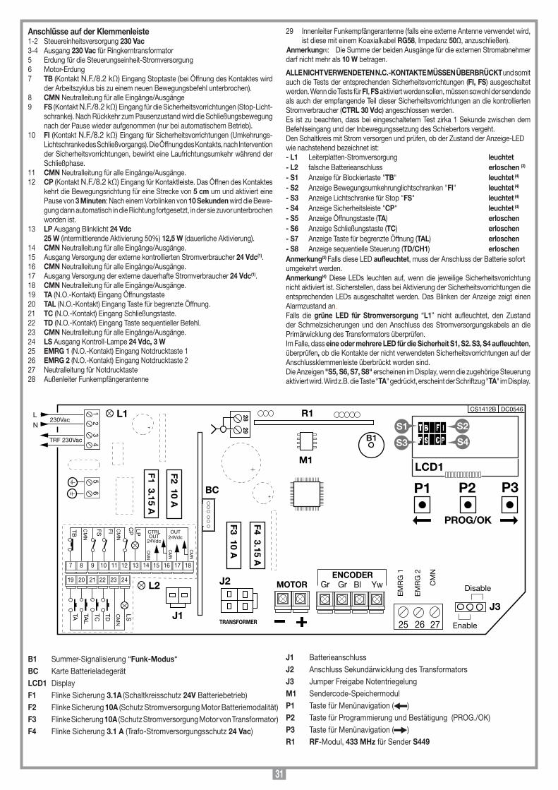
31
Anschlüsse auf der Klemmenleiste1-2 Steuereinheitsversorgung 230 Vac 3-4 Ausgang 230 Vac für Ringkerntransformator5 Erdung für die Steuerungseinheit-Stromversorgung6 Motor-Erdung7 TB (Kontakt N.F./8.2 kΩ) Eingang Stoptaste (bei Öffnung des Kontaktes wird
der Arbeitszyklus bis zu einem neuen Bewegungsbefehl unterbrochen).8 CMN Neutralleitung für alle Eingänge/Ausgänge9 FS (Kontakt N.F./8.2 kΩ) Eingang für die Sicherheitsvorrichtungen (Stop-Licht-
schranke). Nach Rückkehr zum Pausenzustand wird die Schließungsbewegung nach der Pause wieder aufgenommen (nur bei automatischem Betrieb).
10 FI (Kontakt N.F./8.2 kΩ) Eingang für Sicherheitsvorrichtungen (Umkehrungs-Lichtschranke des Schließvorgangs). Die Öffnung des Kontakts, nach Intervention der Sicherheitsvorrichtungen, bewirkt eine Laufrichtungsumkehr während der Schließphase.
11 CMN Neutralleitung für alle Eingänge/Ausgänge.12 CP (Kontakt N.F./8.2 kΩ) Eingang für Kontaktleiste. Das Öffnen des Kontaktes
kehrt die Bewegungsrichtung für eine Strecke von 5 cm um und aktiviert eine Pause von 3 Minuten: Nach einem Vorblinken von 10 Sekunden wird die Bewe-gung dann automatisch in die Richtung fortgesetzt, in der sie zuvor unterbrochen worden ist.
13 LP Ausgang Blinklicht 24 Vdc 25 W (intermittierende Aktivierung 50%) 12,5 W (dauerliche Aktivierung).14 CMN Neutralleitung für alle Eingänge/Ausgänge.15 Ausgang Versorgung der externe kontrollierten Stromverbraucher 24 Vdc(1).16 CMN Neutralleitung für alle Eingänge/Ausgänge.17 Ausgang Versorgung der externe dauerhafte Stromverbraucher 24 Vdc(1).18 CMN Neutralleitung für alle Eingänge/Ausgänge.19 TA (N.O.-Kontakt) Eingang Öffnungstaste20 TAL (N.O.-Kontakt) Eingang Taste für begrenzte Öffnung.21 TC (N.O.-Kontakt) Eingang Schließungstaste.22 TD (N.O.-Kontakt) Eingang Taste sequentieller Befehl.23 CMN Neutralleitung für alle Eingänge/Ausgänge.24 LS Ausgang Kontroll-Lampe 24 Vdc, 3 W25 EMRG 1 (N.O.-Kontakt) Eingang Notdrucktaste 126 EMRG 2 (N.O.-Kontakt) Eingang Notdrucktaste 227 Neutralleitung für Notdrucktaste28 Außenleiter Funkempfängerantenne
29 Innenleiter Funkempfängerantenne (falls eine externe Antenne verwendet wird, ist diese mit einem Koaxialkabel RG58, Impedanz 50Ω, anzuschließen).
Anmerkung(1): Die Summe der beiden Ausgänge für die externen Stromabnehmer darf nicht mehr als 10 W betragen.
ALLE NICHT VERWENDETEN N.C.-KONTAKTE MÜSSEN ÜBERBRÜCKT und somit auch die Tests der entsprechenden Sicherheitsvorrichtungen (FI, FS) ausgeschaltet werden. Wenn die Tests für FI, FS aktiviert werden sollen, müssen sowohl der sendende als auch der empfangende Teil dieser Sicherheitsvorrichtungen an die kontrollierten Stromverbraucher (CTRL 30 Vdc) angeschlossen werden. Es ist zu beachten, dass bei eingeschaltetem Test zirka 1 Sekunde zwischen dem Befehlseingang und der Inbewegungssetzung des Schiebertors vergeht.Den Schaltkreis mit Strom versorgen und prüfen, ob der Zustand der Anzeige-LEDwie nachstehend bezeichnet ist:- L1 Leiterplatten-Stromversorgung leuchtet- L2 falsche Batterieanschluss erloschen (3)
- S1 Anzeige für Blockiertaste "TB" leuchtet (4)
- S2 Anzeige Bewegungsumkehrunglichtschranken "FI" leuchtet (4)
- S3 Anzeige Lichtschranke für Stop "FS" leuchtet (4)
- S4 Anzeige Sicherheitsleiste "CP" leuchtet (4)
- S5 Anzeige Öffnungstaste (TA) erloschen- S6 Anzeige Schließungstaste (TC) erloschen- S7 Anzeige Taste für begrenzte Öffnung (TAL) erloschen- S8 Anzeige sequentielle Steuerung (TD/CH1) erloschenAnmerkung(3) Falls diese LED aufleuchtet, muss der Anschluss der Batterie sofort umgekehrt werden.Anmerkung(4) Diese LEDs leuchten auf, wenn die jeweilige Sicherheitsvorrichtung nicht aktiviert ist. Sicherstellen, dass bei Aktivierung der Sicherheitsvorrichtungen die entsprechenden LEDs ausgeschaltet werden. Das Blinken der Anzeige zeigt einen Alarmzustand an.Falls die grüne LED für Stromversorgung “L1” nicht aufleuchtet, den Zustand der Schmelzsicherungen und den Anschluss des Stromversorgungskabels an die Primärwicklung des Transformators überprüfen.Im Falle, dass eine oder mehrere LED für die Sicherheit S1, S2. S3, S4 aufleuchten, überprüfen, ob die Kontakte der nicht verwendeten Sicherheitsvorrichtungen auf der Anschlussklemmenleiste überbrückt worden sind.Die Anzeigen "S5, S6, S7, S8" erscheinen im Display, wenn die zugehörige Steuerung aktiviert wird. Wird z.B. die Taste "TA" gedrückt, erscheint der Schriftzug "TA" im Display.
Collegamenti scheda base
CC824
16-07-2014
DC0547 Description :
Product Code :
Date :
Drawing number :
P.J.Heath
CARDIN ELETTRONICA S.p.A - 31020 San Vendemiano (TV) Italy - via Raffaello, 36 Tel: 0438/401818 Fax: 0438/401831
Draft :
All rights reserved. Unauthorised copying or use of the information contained in this document is punishable by law
CC824 SCHEDA BASE(con display LCD + manovra di emergenza)
CS1412B DC0546
M1
R1
B1
F3 10 A
F2 10 A
2829
TRANSFORMER
23
14
65
TRF 230Vac
230VacL
N
1211109 18171615141387
22212019 2423
TA TDTC CM
N
TB
CM
N
FS FI LP
CM
N
CM
N
OUT24Vdc
L1LS
25 26 27
CM
N
EM
RG
2
EM
RG
1
TAL
F4 3.15 A
BC
F1 3.15 A
CTRLOUT
24Vdc
CM
N
CM
N
CP
Enable
Disable
LCD1
T B
F S
F I
C P
S1
S3
S2
S4
P1 P2 P3
PROG/OK
L2
J1
J2
J3
YwBlGrGrENCODER
MOTOR
B1 Summer-Signalisierung “Funk-Modus“ BC Karte Batterieladegerät LCD1 DisplayF1 Flinke Sicherung 3.1A (Schaltkreisschutz 24V Batteriebetrieb) F2 Flinke Sicherung 10A (Schutz Stromversorgung Motor Batteriemodalität)F3 Flinke Sicherung 10A (Schutz Stromversorgung Motor von Transformator)F4 Flinke Sicherung 3.1 A (Trafo-Stromversorgungsschutz 24 Vac)
J1 BatterieanschlussJ2 Anschluss Sekundärwicklung des TransformatorsJ3 Jumper Freigabe Notentriegelung M1 Sendercode-SpeichermodulP1 Taste für Menünavigation ( )P2 Taste für Programmierung und Bestätigung (PROG./OK) P3 Taste für Menünavigation ( )R1 RF-Modul, 433 MHz für Sender S449

32
Wert Drehmoment bei Drehmoment bei niedrigen Geschwindigkeit hohen Geschwindigkeit 1 25% 75% 2 25% 100% 3 36% 75%
Wert Drehmoment bei Drehmoment bei niedrigen Geschwindigkeit hohen Geschwindigkeit 4 36% 100% 5 60% 75% 6 60% 100%
Die Pfeile drücken, um den Wert zu erhöhen oder zu vermindern (max. 240 Sekunden).Den Pfeil gedrückt halten, um eine schnelle Wertänderung vorzunehmen.
OK drücken, um die Parameter auf Werkswerte rückzusetzen (ausgenommen die Anzahl der Bewegungen). EXIT drücken, um ohne Änderung der Parameter zubeenden.
“PROG/OK” zum bestätigen
RÜCKKEHR ZUM MENÜ BEWEGUNG
AUSGANG
OK
“PROG/OK” zum Einstellen
PARAMETER-RESET
OK
“PROG/OK” zum Einstellen
PAUSENZEIT: 45
OK
“PROG/OK” zum Einstellen
ABSTAND SCHLIESS (6)
0...9 SCHRITTE
DYNAMISCHE TASTEÖFFNEN-SCHLIESS.ÖFFN.-STOP-SCH
“PROG/OK” zum Einstellen
AUTO. WIEDERSCHL.
ON/OFF“PROG/OK” zum Einstellen
“PROG/OK” zum Einstellen
BLINKLICHTDAUERLEUCHTEND/
BLINKEND“PROG/OK” zum Einstellen
KONTROLLLEUCHTE (1)
DAUERLEUCHTEND/BLINKEND
“PROG/OK” zum Einstellen
UMKEHR-LICHTSCH.(2)
BEI SCHLIESSEN/AUCH BEIM STOP
“PROG/OK” zum Einstellen
“PROG/OK” zum Einstellen
“PROG/OK” zum Einstellen
MOTOR EINBAULINKS
RECHTS“PROG/OK” zum Einstellen
“PROG/OK” zum Einstellen
“PROG/OK” zum bestätigen
RÜCKKEHR ZUM MENÜ OPTIONEN
VORBLINKEN
ON/OFF
TEST FI (3)
ON/OFF
TEST FS
ON/OFF
FUNK-SPEICHERUNG
ON/OFF
AUSGANG
OK
“PROG/OK” zum Einstellen
KONTAKT FI
NC/8K2
KONTAKT TB
NC/8K2
“PROG/OK” zum Einstellen
“PROG/OK” zum Einstellen
“PROG/OK” zum Einstellen
“PROG/OK” zum bestätigen
RÜCKKEHR ZUM MENÜ SICUREZZEVORRICHTUNGEN
KONTAKT FS
NC/8K2
KONTAKT CP
NC/8K2
AUSGANG
OK
“PROG/OK” zum Einstellen
STROMSENSOR (5)
NIVEAU 1...5“PROG/OK” zum Einstellen
“PROG/OK” zum Einstellen
BEGRENZTE ÖFFNUNG
METER 1...9
“PROG/OK” zum Einstellen
KONTRASTEINSTEL.
0...63
KONTRAST
OK
“PROG/OK” zum bestätigen “PROG/OK” zum bestätigen
SICHERHEITSVORR.
OK
“PROG/OK” zum bestätigen
LÖSCHUNG
OK
SPEICHERUNG
OK
“PROG/OK” zum bestätigen
“PROG/OK” zum bestätigen
“PROG/OK” zum bestätigen
“PROG/OK” zum bestätigen
RÜCKKEHR ZUM MENÜ FUNKCODES
TOTAL LÖSCHUNG
OK
KANAL-FUNKTIONEN
OK
AUSGANG
OK
“PROG/OK” zum bestätigen
FUNKCODES
OK
OPTIONEN
OK“PROG/OK” zum bestätigen
BEWEGUNG
OK
BELIEBIGE TASTE
RÜCKKEHR ZUM MENÜ TEST
“PROG/OK” zum bestätigen
TEST
OK“PROG/OK” zum bestätigen
DISPLAY
OK
“PROG/OK” zum bestätigen
“PROG/OK” zum Einstellen
“PROG/OK” zum bestätigen
RÜCKKEHR ZUM MENÜ DISPLAY
AUSGANG
OK
HINTERGRUNDDAUERLEUCHTEND/
60 SEK./30 SEK.
DREHMOMENT WAHL(4)
NIVEAU 1...6
PROGRAMT BF S
F IC P
00.000.001T BF S
F IC P
TESTT BF S
F IC P Die zu
speichernde Kanaltaste auf
dem Sender drücken.
LÖSCHEN LÄUFT
SPEICHERUNG [n ...]
Aktivierung 1
SPEICHERUNG [Nr...]
Aktivierung 2
SPEICHERUNG [Nr ...]
CODE GESPEICHERT
“PROG/OK” zum bestätigen
SPEICHER LÖSCH.?
OK
Die zu löschende
Kanaltaste auf dem Sender
drücken.
LÖSCHUNG [n ...]
Aktivierung 1
LÖSCHUNG [Nr...]
Aktivierung 2
LÖSCHUNG [Nr...]
CODE GELÖSCHT
Ausgang
Die zu löschende
Kanaltaste auf dem Sender
drücken.
Die zu speichernde
Kanaltaste auf dem Sender
drücken.
“PROG/OK” zum bestätigen
KANAL ABEFEHL TD/TAL/TA/TC/BLOCK/KEIN BEFEHL
KANAL BBEFEHL TD/TAL/TA/TC/BLOCK/KEIN BEFEHL
“PROG/OK” zum bestätigen “PROG/OK” zum bestätigen
KANAL CBEFEHL TD/TAL/TA/TC/BLOCK/KEIN BEFEHL
“PROG/OK” zum bestätigen
KANAL DBEFEHL TD/TAL/TA/TC/BLOCK/KEIN BEFEHL
“PROG/OK” zum bestätigen
RÜCKKEHR ZUM MENÜ FUNKCODES
AUSGANG
OK
FALSCH POST BF S
F ICP
STOP PROGT BF S
F ICP
PROGRAMT BF S
F ICP Blinkend auf dem Display. Zur Programmierung des Systems sich in den Programmiermodus begeben.
Bei Normalbetrieb wird stattdessen angezeigt, dass die automatische Rückstellung (siehe Seite 36) ausgeführt wird. In diesem Fall gibt jeder eintreffende Befehl (TA, TC, TAL oder TD) zur sofortigen Ausführung dieses Vorganges Anlass.
Dieser Zustand tritt ein, wenn ein Ausschaltgliedkontakt (FI, FS, CP) während der Encoderprogrammierung oder automatische Rückstellung aktiviert wird. Nachdem der passive Zustand der Sicherheitsvorrichtungen wiederhergestellt ist, nimmt der Torügel seine Bewegung automatisch wieder auf. Dies geschieht auch, wenn die Netzstromversorgung während der Programmierung ausfällt.
Der Zustand der Sicherheitsvorrichtungen muss kontrolliert werden, wobei zu überprüfen ist, ob diese in den Alarmzustand treten (diesbezügliche LED erloschen), wenn ein Hindernis sich in deren Aktionsradius bendet. Wenn eine Anomalie gefunden wird, ist die fehlerhafte Sicherheitsvorrichtung auszuwechseln oder der entsprechende Eingang zu überbrücken und der Test dieser Sicherheitsvorrichtung abzuschalten (Menu Optionen).
Dieses Problem tritt auf, wenn die Steuerung dem Motor einen Befehl erteilt, dieser aber nicht anläuft. Es brauchen nur die Stromanschlüsse des Motors und die Schmelzsicherungen "F2" und "F3" überprüft werden. Danach noch mal einen Öffnungs- oder Schließungsbefehl geben. Wenn der Motor auch jetzt nicht anläuft, könnte das Problem bei der Mechanik des Motors oder bei der Steuereinheit liegen.
Wenn dies bei der normalen Verwendung des Motors auftritt, bedeutet dies, dass ein Problem mit der Encoder-Signalen besteht. Die Anschlüsse überprüfen und die automatische Rückstellung ausführen.
Die Laufrichtung des Torügels ist anders als wie vom Encoder festgelegt. (z.B.: Das Schiebetor schließt während die Steuerung die Öffnung ausführt). Den Anschluss der Motoren-Stromversorgung überprüfen.
Fehlermeldung des Stromsensors: Bei stillstehendem Motor zeigt dieses Symbol an, dass ein Problem mit dem Stromsensor besteht.
Die Aktivierung der Leiste führt sowohl bei der Schließung als auch bei der Öffnung zwecks Beseitigung eines eventuellen Hindernisses zu einer sofortigen Umkehrung der Torügelbewegung für eine Strecke von 5 cm. Nach einem Stillstand von 3 Minuten erfolgt dann nach einem vorherigen Blinken von 10 Sekunden wieder die Bewegung in die zuvor unterbrochene Richtung.
Die Aktivierung des Sensors führt sowohl bei der Schließung als auch bei der Öffnung zwecks Beseitigung eines eventuellen Hindernisses zu einer sofortigen Umkehrung der Torügelbewegung für eine Strecke von 5 cm. Nach einem Stillstand von 3 Minuten erfolgt dann nach einem vorherigen Blinken von 10 Sekunden wieder die Bewegung in die zuvor unterbrochene Richtung.
SICHER.FHLT BF S
F ICP
FEHLE. MOT1T BF S
F ICP
FEHLE. ENC1T BF S
F ICP
FEHLE. DIR1T BF S
F ICP
FEHL. SENS1T BF S
ICP
AKT. LEISTET BF S
ICP
AKT. SENST BF S
ICP
Alarmsignalisierungen
AUTO PROGT BF S
F ICP
ÖFFNENT BF S
F ICP
PAUSET BF S
F ICP
Programmierung der Pausenzeit oder Pause für die automatische Wiederschliessung (nur wenn befähigt)
Automatische Programmierung im Gange
Öffnungsphase
Stop während der Öffnungsphase
Schliessungsphase
Stop während der Schliessungsphase
Aktualisierung des Strommess-Sensors (nur während der Programmierverfahren)
Test-Modus
Batteriebetrieb mit geladener Batterie
Entladene Batterie. Der Motor hält an und alle Steuerungen
sind gesperrt.
STOP ÖFFNET BF S
F ICP
AKT. SNS1T BF S
F ICP
TESTT BF S
ICP
BATT. [99%]T BF S
IC P
Betriebssignalisierungen
SCHLIESST BF S
F ICP
STOP SCHLNT BF S
F ICP
BATT. [0%]T BF S
ICP
AUTO PROG
F
F
F F
F
F
“PROG/OK” zum Einstellen
ABST. ÖFFN.-ANSCHL. (6)
0...9 SCHRITTE
FW_0.11
• Alle Funktionen des Steuergeräts können über das Menü im Display "LCD1" mit den drei darunterliegenden Tasten eingestellt werden:- Für das Navigieren im Menü und/oder die Einstellung des Kontrasts im Display die Pfeile benutzen;- “PROG/OK” für die Änderung der Einstellung des ausgewählten Parameters und/oder für die Bestätigung benutzen.
Anmerkung:1) Die Kontrollleuchte blinkt langsam während der Öffnung, schnell während der Schließung, leuchtet
ohne Unterbrechung wenn das Tor bei nicht vollständiger Schließung blockiert ist und erlischt, wenn das Tor vollständig geschlossen ist.
2) Betriebsmodus FI:- FI auch bei Blockierung aktiviert: Wenn die Lichtschranke in Alarmstellung sind und das Tor sich im
Blockierstatus befindet, wird kein Bewegungsbefehl (auch kein Öffnungsbefehl) angenommen;- FI nur beim Schließen aktiviert: In beiden Fällen verursacht die Aktivierung der Sicherheitsvorrichtung
FI während der Schließung eine Bewegungsumkehrung.3) Lichtschranketest (FI/FS) Wenn die Tests der Sicherheitsvorrichtungen aktiviert werden sollen, müssen sowohl der sendende Teil
als auch der empfangende Teil an die kontrollierten Stromabnehmer (CTRL 24Vdc) angeschlossen werden. Bei eingeschaltetem Test vergeht ca. eine Sekunde zwischen dem Empfang eines Befehls und dessen tatsächlicher Ausführung.
4)
PROGRAMMIERVERFAHREN (Einstellungen der Parameters)
5) Einstellung des Stromsensors:- Niveau 1 = Aufnahme des Motors + 2 Ampere- Niveau 2 = Aufnahme des Motors + 2.5 Ampere- Niveau 3 = Aufnahme des Motors + 3 Ampere- Niveau 4 = Aufnahme des Motors + 4 Ampere - Niveau 5 = Aufnahme des Motors + 5 AmpereDie Steuerung kontrolliert die Aufnahme des Motors, wobei sie die Erhöhung der Beanspruchung über die beim normalen Betrieb erlaubten Grenzwerte hinaus erfasst und als zusätzliche Sicherheitsvorrichtung eingreift. 6) Einstellung des Abstands des Schließ-/Öffnungsanschlags: Für die Vergrößerung oder Verkleinerung dieses Abstands den Parameter von 0 bis 9 ändern (von ca. 0 bis 6 cm). Die Defaulteinstellung des Geräts ist Niveau
4. Auf diese Weise schlägt das Tor nicht am Anschläge an, sondern bleibt einen Zentimeter davor stehen.

33
Die Pfeile drücken, um den Wert zu erhöhen oder zu vermindern (max. 240 Sekunden).Den Pfeil gedrückt halten, um eine schnelle Wertänderung vorzunehmen.
OK drücken, um die Parameter auf Werkswerte rückzusetzen (ausgenommen die Anzahl der Bewegungen). EXIT drücken, um ohne Änderung der Parameter zubeenden.
“PROG/OK” zum bestätigen
RÜCKKEHR ZUM MENÜ BEWEGUNG
AUSGANG
OK
“PROG/OK” zum Einstellen
PARAMETER-RESET
OK
“PROG/OK” zum Einstellen
PAUSENZEIT: 45
OK
“PROG/OK” zum Einstellen
ABSTAND SCHLIESS (6)
0...9 SCHRITTE
DYNAMISCHE TASTEÖFFNEN-SCHLIESS.ÖFFN.-STOP-SCH
“PROG/OK” zum Einstellen
AUTO. WIEDERSCHL.
ON/OFF“PROG/OK” zum Einstellen
“PROG/OK” zum Einstellen
BLINKLICHTDAUERLEUCHTEND/
BLINKEND“PROG/OK” zum Einstellen
KONTROLLLEUCHTE (1)
DAUERLEUCHTEND/BLINKEND
“PROG/OK” zum Einstellen
UMKEHR-LICHTSCH.(2)
BEI SCHLIESSEN/AUCH BEIM STOP
“PROG/OK” zum Einstellen
“PROG/OK” zum Einstellen
“PROG/OK” zum Einstellen
MOTOR EINBAULINKS
RECHTS“PROG/OK” zum Einstellen
“PROG/OK” zum Einstellen
“PROG/OK” zum bestätigen
RÜCKKEHR ZUM MENÜ OPTIONEN
VORBLINKEN
ON/OFF
TEST FI (3)
ON/OFF
TEST FS
ON/OFF
FUNK-SPEICHERUNG
ON/OFF
AUSGANG
OK
“PROG/OK” zum Einstellen
KONTAKT FI
NC/8K2
KONTAKT TB
NC/8K2
“PROG/OK” zum Einstellen
“PROG/OK” zum Einstellen
“PROG/OK” zum Einstellen
“PROG/OK” zum bestätigen
RÜCKKEHR ZUM MENÜ SICUREZZEVORRICHTUNGEN
KONTAKT FS
NC/8K2
KONTAKT CP
NC/8K2
AUSGANG
OK
“PROG/OK” zum Einstellen
STROMSENSOR (5)
NIVEAU 1...5“PROG/OK” zum Einstellen
“PROG/OK” zum Einstellen
BEGRENZTE ÖFFNUNG
METER 1...9
“PROG/OK” zum Einstellen
KONTRASTEINSTEL.
0...63
KONTRAST
OK
“PROG/OK” zum bestätigen “PROG/OK” zum bestätigen
SICHERHEITSVORR.
OK
“PROG/OK” zum bestätigen
LÖSCHUNG
OK
SPEICHERUNG
OK
“PROG/OK” zum bestätigen
“PROG/OK” zum bestätigen
“PROG/OK” zum bestätigen
“PROG/OK” zum bestätigen
RÜCKKEHR ZUM MENÜ FUNKCODES
TOTAL LÖSCHUNG
OK
KANAL-FUNKTIONEN
OK
AUSGANG
OK
“PROG/OK” zum bestätigen
FUNKCODES
OK
OPTIONEN
OK“PROG/OK” zum bestätigen
BEWEGUNG
OK
BELIEBIGE TASTE
RÜCKKEHR ZUM MENÜ TEST
“PROG/OK” zum bestätigen
TEST
OK“PROG/OK” zum bestätigen
DISPLAY
OK
“PROG/OK” zum bestätigen
“PROG/OK” zum Einstellen
“PROG/OK” zum bestätigen
RÜCKKEHR ZUM MENÜ DISPLAY
AUSGANG
OK
HINTERGRUNDDAUERLEUCHTEND/
60 SEK./30 SEK.
DREHMOMENT WAHL(4)
NIVEAU 1...6
PROGRAMT BF S
F IC P
00.000.001T BF S
F IC P
TESTT BF S
F IC P Die zu
speichernde Kanaltaste auf
dem Sender drücken.
LÖSCHEN LÄUFT
SPEICHERUNG [n ...]
Aktivierung 1
SPEICHERUNG [Nr...]
Aktivierung 2
SPEICHERUNG [Nr ...]
CODE GESPEICHERT
“PROG/OK” zum bestätigen
SPEICHER LÖSCH.?
OK
Die zu löschende
Kanaltaste auf dem Sender
drücken.
LÖSCHUNG [n ...]
Aktivierung 1
LÖSCHUNG [Nr...]
Aktivierung 2
LÖSCHUNG [Nr...]
CODE GELÖSCHT
Ausgang
Die zu löschende
Kanaltaste auf dem Sender
drücken.
Die zu speichernde
Kanaltaste auf dem Sender
drücken.
“PROG/OK” zum bestätigen
KANAL ABEFEHL TD/TAL/TA/TC/BLOCK/KEIN BEFEHL
KANAL BBEFEHL TD/TAL/TA/TC/BLOCK/KEIN BEFEHL
“PROG/OK” zum bestätigen “PROG/OK” zum bestätigen
KANAL CBEFEHL TD/TAL/TA/TC/BLOCK/KEIN BEFEHL
“PROG/OK” zum bestätigen
KANAL DBEFEHL TD/TAL/TA/TC/BLOCK/KEIN BEFEHL
“PROG/OK” zum bestätigen
RÜCKKEHR ZUM MENÜ FUNKCODES
AUSGANG
OK
FALSCH POST BF S
F ICP
STOP PROGT BF S
F ICP
PROGRAMT BF S
F ICP Blinkend auf dem Display. Zur Programmierung des Systems sich in den Programmiermodus begeben.
Bei Normalbetrieb wird stattdessen angezeigt, dass die automatische Rückstellung (siehe Seite 36) ausgeführt wird. In diesem Fall gibt jeder eintreffende Befehl (TA, TC, TAL oder TD) zur sofortigen Ausführung dieses Vorganges Anlass.
Dieser Zustand tritt ein, wenn ein Ausschaltgliedkontakt (FI, FS, CP) während der Encoderprogrammierung oder automatische Rückstellung aktiviert wird. Nachdem der passive Zustand der Sicherheitsvorrichtungen wiederhergestellt ist, nimmt der Torügel seine Bewegung automatisch wieder auf. Dies geschieht auch, wenn die Netzstromversorgung während der Programmierung ausfällt.
Der Zustand der Sicherheitsvorrichtungen muss kontrolliert werden, wobei zu überprüfen ist, ob diese in den Alarmzustand treten (diesbezügliche LED erloschen), wenn ein Hindernis sich in deren Aktionsradius bendet. Wenn eine Anomalie gefunden wird, ist die fehlerhafte Sicherheitsvorrichtung auszuwechseln oder der entsprechende Eingang zu überbrücken und der Test dieser Sicherheitsvorrichtung abzuschalten (Menu Optionen).
Dieses Problem tritt auf, wenn die Steuerung dem Motor einen Befehl erteilt, dieser aber nicht anläuft. Es brauchen nur die Stromanschlüsse des Motors und die Schmelzsicherungen "F2" und "F3" überprüft werden. Danach noch mal einen Öffnungs- oder Schließungsbefehl geben. Wenn der Motor auch jetzt nicht anläuft, könnte das Problem bei der Mechanik des Motors oder bei der Steuereinheit liegen.
Wenn dies bei der normalen Verwendung des Motors auftritt, bedeutet dies, dass ein Problem mit der Encoder-Signalen besteht. Die Anschlüsse überprüfen und die automatische Rückstellung ausführen.
Die Laufrichtung des Torügels ist anders als wie vom Encoder festgelegt. (z.B.: Das Schiebetor schließt während die Steuerung die Öffnung ausführt). Den Anschluss der Motoren-Stromversorgung überprüfen.
Fehlermeldung des Stromsensors: Bei stillstehendem Motor zeigt dieses Symbol an, dass ein Problem mit dem Stromsensor besteht.
Die Aktivierung der Leiste führt sowohl bei der Schließung als auch bei der Öffnung zwecks Beseitigung eines eventuellen Hindernisses zu einer sofortigen Umkehrung der Torügelbewegung für eine Strecke von 5 cm. Nach einem Stillstand von 3 Minuten erfolgt dann nach einem vorherigen Blinken von 10 Sekunden wieder die Bewegung in die zuvor unterbrochene Richtung.
Die Aktivierung des Sensors führt sowohl bei der Schließung als auch bei der Öffnung zwecks Beseitigung eines eventuellen Hindernisses zu einer sofortigen Umkehrung der Torügelbewegung für eine Strecke von 5 cm. Nach einem Stillstand von 3 Minuten erfolgt dann nach einem vorherigen Blinken von 10 Sekunden wieder die Bewegung in die zuvor unterbrochene Richtung.
SICHER.FHLT BF S
F ICP
FEHLE. MOT1T BF S
F ICP
FEHLE. ENC1T BF S
F ICP
FEHLE. DIR1T BF S
F ICP
FEHL. SENS1T BF S
ICP
AKT. LEISTET BF S
ICP
AKT. SENST BF S
ICP
Alarmsignalisierungen
AUTO PROGT BF S
F ICP
ÖFFNENT BF S
F ICP
PAUSET BF S
F ICP
Programmierung der Pausenzeit oder Pause für die automatische Wiederschliessung (nur wenn befähigt)
Automatische Programmierung im Gange
Öffnungsphase
Stop während der Öffnungsphase
Schliessungsphase
Stop während der Schliessungsphase
Aktualisierung des Strommess-Sensors (nur während der Programmierverfahren)
Test-Modus
Batteriebetrieb mit geladener Batterie
Entladene Batterie. Der Motor hält an und alle Steuerungen
sind gesperrt.
STOP ÖFFNET BF S
F ICP
AKT. SNS1T BF S
F ICP
TESTT BF S
ICP
BATT. [99%]T BF S
IC P
Betriebssignalisierungen
SCHLIESST BF S
F ICP
STOP SCHLNT BF S
F ICP
BATT. [0%]T BF S
ICP
AUTO PROG
F
F
F F
F
F
“PROG/OK” zum Einstellen
ABST. ÖFFN.-ANSCHL. (6)
0...9 SCHRITTE
FW_0.11
• Die wichtigsten Betriebsparameter (z.B. Installation rechts/links) müssen im Speichermenü eingestellt werden.• Wenn Sicherheitsvorrichtungen mit Kontakt 8.2 kΩ, vorhanden sind, ist die Einstellung im Menü Sicherheitsvorrichtungen zu ändern.• Vor der Programmierung des Torlaufs ist der richtige Motor unter der Position "Motorauswahl" des Menüs "Bewegung" auszuwählen.
Auswahl der Sprache:
• Für den Zugriff auf das Untermenü die Tasten rechts und links gleichzeitig drücken.
• Die Taste rechts oder links drücken, um die Sprache zu wechseln : Italienisch - Deutsch.
• Zur Bestätigung der Sprache die Taste "PROG/OK" drücken.
“PROG/OK” bestätigen
DEUTSCH
OK
Beide Pfeile gleichzeitig drücken um in das Sprachen-
Untermenü zu gelangen
PROGRAMT BF S
F IC P

34
PROGRAMMIERVERFAHREN (Torlauf und Stromsensor)
Speichermodul (M1)Herausnehmbar, verfügt über nicht flüchtigen EEPROM-Speicher, beinhaltet die Sendercodes und ermöglicht die Speicherung von 300 Codes. Die Codes ver-bleiben im Speicher auch in Abwesenheit der Stromversorgung. Bevor die erste Speicherung vorgenommen wird, muss zuerst der Speicher vollkommen gelöscht werden. Falls die elektronische Karte im Falle eines Defekts ausgewechselt werden muss, kann das Speichermodul aus dieser herausgenommen und in die neue Karte wie in Abb. 2 aufgezeigt eingesteckt werden.
VERWALTUNG DER SENDERCODES
Speicherung eines Kanals:1. Auf die Position "SPEICHERUNG" des Menüs "FUNKCODES" gehen und über
die Taste "PROG/OK“ bestätigen: Im LCD-Display blinkt der Schriftzug "Aktivierung 1". 2. Den Sender auf dem zu speichernden Kanal einschalten: Im LCD-Display blinkt der Schriftzug "Aktivierung 2". 3. Den Sender ein zweites Mal aktivieren (denselben Sender, denselben Kanal *):
Im LCD-Display blinkt der Schriftzug "COD. GESPEICHERT"In der ersten Textzeile wird in Klammern die Anzahl der im Speicher vorhandenen Kanäle angezeigt. * Wird versehentlich ein anderer Kanal als der der ersten Akti-vierung aktiviert (unter Punkt 3), wird der Vorgang automatisch annulliert und im LCD-Display blinkt der Schriftzug "Aktivierung 1".
Anmerkung: Es ist nicht möglich, einen Code zu speichern, der sich schon im Speicher befindet: In einem solchen Fall blinkt während der Aktivierung der Funk-steuerung (unter Punkt 1) im LCD-Display der Schriftzug "COD. SCHON GESP.".
Löschung eines Kanals:1. Auf die Position "LÖSCHUNG" des Menüs "FUNKCODES" gehen und über die
Taste "PROG/OK“ bestätigen: Im LCD-Display blinkt der Schriftzug "Aktivierung 1". 2. Den Sender auf dem zu löschenden Kanal einschalten: Im LCD-Display blinkt der Schriftzug "Aktivierung 2". 3. Den Sender ein zweites Mal aktivieren (denselben Sender, denselben Kanal *):
Im LCD-Display blinkt der Schriftzug "COD. GELÖSCHT".In der ersten Textzeile wird in Klammern die Anzahl der im Speicher vorhandenen Kanäle angezeigt. * Wird versehentlich ein anderer Kanal als der der ersten Akti-vierung aktiviert (unter Punkt 3), wird der Vorgang automatisch annulliert und im LCD-Display blinkt der Schriftzug "Aktivierung 1".
Anmerkung: Es ist nicht möglich, einen Code zu löschen, der nicht im Speicher vorhanden ist: In einem solchen Fall blinkt während der Aktivierung der Funk-steuerung (unter Punkt 1) im LCD-Display der Schriftzug "COD. NICHT GESP.".
Vollständige Löschung des Benutzerspeichers:1. Auf die Position "VOLLST. LÖSCH." des Menüs "FUNKCODES" gehen und über
die Taste "PROG/OK" bestätigen: Im LCD-Display erscheint die Aufforderung zur Bestätigung des Vorgangs "SPEICHER LÖSCH.?" (einen der beiden Pfeile drücken, um aus diesem Vorgang herauszugehen).
2. Die Taste "PROG/OK" drücken, um die vollständige Löschung zu bestätigen: Im LCD-Display erscheint der Schriftzug "LÖSCH. LÄUFT" mit einer Progres-
sionsleiste darunter, die das Laufen des Vorgangs anzeigt.3. Nach der vollständigen Löschung des Speichers kehrt das Display auf die
Position "VOLLST. LÖSCH." zurück.
Speicherung weiterer Kanäle über Funk • Die Speicherung kann auch über Funk aktiviert werden (ohne die Dose zu öffnen,
in der sich das Steuergerät befindet), wenn die Einstellung "FUNKSPEICHE-RUNG" im Menü "OPTIONEN" aktiviert wurde.
1. Eine Funksteuerung verwenden, bei der mindestens eine der Kanaltasten "A-B-C-D" schon auf dem Emp-fänger gespeichert worden ist, und die Taste im Innern der Funksteuerung drücken wie in Abbild aufgezeigt.
Anmerkung: Alle von der Funksteuerung erreichbaren Empfänger und die min-destens einen Kanal des Senders gespeichert haben, aktivieren gleichzeitig den Summer "B1" (Abb. 2).2. Um den Empfänger zu wählen, in welchem die neue Codenummer gespeichert
wird, eine der Kanaltasten des gleichen Senders drücken. Die Empfänger, die nicht den Code dieser Taste besitzen, schalten sich ab und geben dabei einen 5 Sekunden dauernden Bip-Ton von sich. Der Empfänger, der stattdessen den Code gespeichert hat, gibt einen andersartigen, eine Sekunde dauernden Bip-Ton von sich und begibt sich in den "funkgesteuerten" Speichermodus.
3. Die vorab auf dem zu speichernden Sender gewählte Kanaltaste drücken. Bei erfolgter Speicherung gibt der Empfänger 2, eine halbe Sekunde lang dauernde Bip-Töne von sich. Danach ist der Empfänger bereit, einen anderen Code zu speichern.
4. Um den Modus zu beenden, 3 Sekunden ohne einen Code zu speichern ver-streichen lassen. Der Empfänger gibt einen 5 Sekunden dauernden Bip-Ton von sich und verlässt den Speichermodus.
Anmerkung: Wenn der Speicher voll ist, gibt der Summer zehn, schnell aufeinan-derfolgende Bip-Töne von sich und beendet automatisch den "funkgesteuerten" Speichermodus. Das Gleiche geschieht auch bei jedem Versuch sich bei vollem Speicher in den "funkgesteuerten" Speichermodus zu begeben.
Anmerkung: Das Funkspeicherungsverfahren kann erst nach fertiggestellter Programmierung und außerhalb des Konfigurations-/Programmiermenüs durch-geführt werden
• Das Vorhandensein der Öffnungs- und Schließungsanschläge ist obliga-torisch.
• Sicherstellen, dass sich die Sicherheitsvorrichtungen in Ruheposition befinden und dass die Karte mit Netzstrom versorgt wird: Anderenfalls ist kein Zugriff auf die Programmierung möglich.
• Eine Programmierung der Zeiten im Batteriebetrieb ist nicht möglich. • Vor der Programmierung sind die Betriebsparameter unter dem Menüpunkt
"OPTIONEN" einzustellen.
NEUPOSITIONIERUNG
Achtung! Während der Neupositionierung könnte der Wert des Stromsen-sors verändert sein (durch maxmales Drehmomentswert ersetz). Am Ende des Vorgangs kehrt er automatisch auf den ausgewählten Wert zurück.
Sollte es zu einer Blockierung der Steuerung aufgrund einer Anomalie der Enco-derzählung ("ENC-Fehler" im Display), eines Resets der Steuerung ("Außer Pos.") oder eines Problems mit dem Motor ("Fehler Mot") kommen, blinken das Blinklicht und die Kontrollleuchte gleichzeitig, wobei sie sich für 2 Sekunden einschalten und für 10 Sekunden ausschalten. Wird in dieser Phase ein Befehl (TA, TC, TAL oder TD) an die Steuerung gesendet, bringt die Steuerung selbst das Tor automatisch auf niedriger Geschwindigkeit bis zum Schließanschlag (2 Mal wie im Programmierverfahren), um die Position wiederzufinden. Danach nimmt die Steuerung den normalen Betrieb wieder auf (wenn ein "TA"-Befehl gegeben wird, wird das Rückstellverfahren mit der Öffnung ausgeführt). Während der Neupositionierungsphase wird kein Befehl angenommen und die Sicherheitsvorrichtungen blockieren die Bewegung nur solange sie sich in Alarmstellung befinden. Zur Unterbrechung des Neupositionierungsverfahrens, die Taste "PROG" oder "TB" drücken.
Die Automatisierung kann mittels einer Funkfernsteuerung ferngesteuert werden; jeder Kanal kann konfiguriert werden, indem aus den 6 verfügbaren Funktionen ausgewählt wird: Öffnen - Schließen – Begrenzte Öffnung – Sequenzieller Befehl - Blockierung. Für die Konfigurierung der Funktionen auf den Kanälen "A","B","C","D" wird die Position "KANALFUNKTION" im Menü "FUNKCODES" benutzt. Die sequenzielle Steuerung kann im Menü "OPTIONEN" unter "Öffnen-Blo-ckierung-Schließen-Blockierung" oder "Öffnen-Schließen" konfiguriert werden.
BEFEHLEINGABE ÜBER FUNK
1...4... Sek.
Start der Pausenzeitzählung (min 2 Sekunden; max 120 Sekunden), angezeigt durch den auf dem display blinkenden Schriftzug “PAUSE”.
Die Taste “PROG” drücken um die Pausenzeitzählung zu bestätigen. Jetzt schliesst der Torügel sich langsam zur Aufndung der vollständigen Öffnung .
Wenn der Torügel am Öffnungsanschlag angekommen ist, wird dessen Bewegungsrichtung umgekehrt und nach einer Laufstrecke von einigen Zentimetern führt er erneut wieder die Öffnungsbewegung zum aufnden der Anschlagsposition durch. Jetzt beginnt die Schliessung. Wenn der Torügel am Anschlag angekommen ist, wird dessen Bewegungsrichtung umgekehrt und nach einer Laufstrecke von einigen Zentimetern führt er erneut wieder die Schliessung zum aufnden der Anschlagsposition durch.
Die elektronische Steuerungs führt jetzt einem kompletten Öffnungs- und Schliessungslauf zur Eichung des Strommessers durch.
Wenn der Torügel die vollständige Schliessung erreicht, speichert die Steuerung die Parameter und tritt aus dem Programmierverfahren aus.
Das Verfahren war nicht erfolgreich. Die Programmierung muss wiederholt werden
Die Taste “PROG” länger als 4 Sek. lang gedrückt halten
“PROG/OK” 4 Sek. halten
“PROG/OK”
“PROG/OK”
PROGRAMT BF S
F IC P
T BF S
F IC P
PROGRAMT BF S
F IC P
PAUSE
AUTO PROG.
PAUSE 005
AUTO PROG.
T BF S
F IC P
ÖFFNUNG
AUTO PROG.
AUTO-PROGRAMMIERUNG ZYKLUS
T BF S
F IC P
SCHLIESSUNG
AUTO PROG.
T BF S
F IC P
T BF S
F IC P
MEMORIZZAZIONE CODICE TX-RX
RCQ449100
13-04-2001
DM0531 Description :
Product Code :
Date :
Drawing number :
P.J.Heath
CARDIN ELETTRONICA S.p.A - 31020 San Vendemiano (TV) Italy - via Raffaello, 36 Tel: 0438/401818 Fax: 0438/401831
Draft :
All rights reserved. Unauthorised copying or use of the information contained in this document is punishable by law
MR

35
ANTENNENANSCHLUSS Eine abgestimmte Antenne ANS400, benutzen, die über ein Koaxialkabel RG58 (imp. 50Ω) mit einer Länge von max. 15 m an den Empfänger anzuschließen ist.
1) AutomatischSie wird ausgewählt, indem das automatische Wiederschließen freigegeben wird (Autom. Wiederschl. "ON" im Display). Ausgehend vom vollständig geschlossenen Zustand beginnt der Öffnungsbefehl einen vollständigen Betriebszyklus, der mit dem automatischen Wiederschließen endet. Das automatische Wiederschließen schaltet sich ein mit einer Verzögerung gleich der programmierten Pausenzeit (mindestens 2 Sekunden) ab dem Ende des Öff-nungsvorgangs oder in dem Moment, in dem die Lichtschranken zum letzten Mal während der Pausenzeit angesprochen haben (das Ansprechen der Lichtschranken bewirkt ein Reset der Pausenzeit). Während der Pausenzeit blinkt im Display der Schriftzug "Pause" und es erscheint die Zahl der Sekunden, die bis zum Ablauf der Pausenzeit verbleiben. Das Drü-cken der Blockiertaste während der Pausenzeit verhindert das automatische Wiederschließen mit daraus folgernder Blockierung des Blinkens im Display. Die Kontrollleuchte bleibt eingeschaltet, wenn das Tor nicht vollständig geschlossen ist.
2) HalbautomatischSie wird ausgewählt, indem das automatische Wiederschließen gesperrt wird (Autom. Wiederschl. "OFF" im Display). Der Arbeitszyklus wird über getrennte Öffnungs- und Schließbefehle gesteuert. Nach Ankunft in der Position der vollständigen Öffnung wartet das System auf einen Schließbefehl über Funk oder über die Taste, um den Zyklus fertigzustellen. Die Kontrollleuchte bleibt eingeschaltet, wenn das Tor nicht vollständig geschlossen ist.
3) Manuelle Betätigung mit entriegeltem MotorWird der Motor entriegelt, kann das Tor von Hand bewegt werden; nach der erneuten Verriegelung sorgt die Steuerung nach zwei aufeinanderfolgenden Versuchen für die Erreichung des Anschlags für die Wiederherstellung der Position.
4) Notfall-BetätigungDie Notentriegelung ist per Default gesperrt. Um sie freizugeben, ist der Jumper J3 auf "ENABLE" zu stellen (Abb. 2). Wenn die elektronische Steuerung wegen eines Defektes nicht mehr auf die Befehlseingabe anspricht, sind die Eingänge EMRG1 oder EMRG2 zur manuellen Betätigung des Tors zu verwenden. Die Eingänge EMRG1 und EMRG2 schließen die Logik aus und haben somit einen direkten Einfluss auf die Kontrolle des Motors. Die Bewegung des Tors erfolgt auf Nenngeschwindigkeit und die Richtung der Bewegung hängt ab von der Installati-onsposition des Getriebemotors:- bei links installiertem Getriebemotor schließt EMRG1 und EMRG2 öffnet;- bei rechts installiertem Getriebemotor öffnet EMRG1 und EMRG2 schließt.
Achtung! Während der Notfall-Betätigung sind alle Sicherheitsvorrich-tungen abgeschaltet und die Torstellung wird nicht kontrolliert. Deshalb müssen die Befehlstasten vor Ankunft des Tors am Endanschlag losgelassen werden. Die Notfall-Betätigung sollte nur im extremen Notfall verwendet werden.
Nach einer Notfall-Betätigung "verliert" die elektronische Steuerung die Torposition ("Außer Pos." im Display) und daher wird bei Wiederherstellung des normalen Betriebs die automatische Neupositionierung vorgenommen.
• Wenn die Betriebsart "Öffnen-Schließen" für den "TD" eingestellt ist (Menu "OPTIONEN"), startet die Betätigung des "TAL" die Phase der begrenzten Öffnung (nur aus dem Zustand "vollständig geschlossen") und hat solange die Öffnung dauert keine Wirkung mehr.
Danach beginnt bei betätigung des "TAL" der Schließvorgang und nun wird der "TAL" bis zum vollständigen Schließen nicht mehr gesteuert.
• Wenn die Betriebsart "Öffnen-Blockierung-Schließen" für den "TD" eingestellt ist (Menu "OPTIONEN") startet die Betätigung des "TAL" die Phase der begrenz-ten Öffnung (nur aus dem Zustand "vollständig geschlossen") und wenn er während der Öffnungsbewegung betätigt wird, bewirkt er die Blockierung; eine dritte Betätigung startet die Schließbewegung und nun wird der "TAL" bis zum vollständigen Schließen nicht mehr gesteuert.
• Wenn während der begrenzten Öffnung ein Öffnungsbefehl ankommt, wird die bis dahin teilweise Öffnung vollständig.
Das Ansprechen der Lichtschranke FI während der Schließphase aus der begrenzten Öffnung bewirkt das nur teilweise Wiederöffnen (es wird nur so weit wieder geöffnet, wie sich das Tor wieder geschlossen hatte).
Anmerkung: Der Befehl der begrenzten Öffnung kann auch über die Benutzung der zweiten Funkfunktion gegeben werden. Das Öffnen des Tors kann ausgewählt werden von 1 bis 9 Meter über die Änderung des Parameters "Begrenzte Öffnung".
Die Vorrichtung erlaubt den Betrieb des Systems auch bei fehlender Netzversor-gung. • Die Steuerung verfügt über einen Ladekreis für NiMH-Batterien auf 24V, der
gesteuert wird von einem eigenen Mikrocontroller, der die Spannung abhängig vom Zustand der Batterie regelt. Der Ladekreis wird über einen Stecker eingeschaltet.
Um das Risiko der Überhitzung zu vermeiden, sind nur vom Hersteller gelieferte Batterien zu benutzen (Ersatzteil-Nr. 999540). Wenn die Batterie Zeichen von Beschädigungen aufweist, ist sie auszutauschen. Die Bat-terie muss von qualifiziertem Personal installiert und herausgenommen werden. Verbrauchte Batterien dürfen nicht in den Hausmüll gegeben werden, sondern sind gemäß den geltenden Vorschriften zu entsorgen.
• Die Rückkehr zum normalen Betrieb erfolgt bei der Wiederherstellung der Netzspannung; um erneut benutzt werden zu können, muss sich die Batterie aufladen. Die Ladezeit kann bei einer funktionstüchtigen Batterie bis zu einem Höchstzeitraum von 16 Stunden dauern: Wenn die benötigte Zeit höher ist, muss ein Austausch erwägt werden. Um stets Höchstleistungen zu erhalten, wird empfohlen, die Batterie alle drei Jahre auszutauschen.
• Wenn das Tor steht, sind die externen kontrollierten Stromabnehmer (CTRL 24 Vdc) nicht mit Strom versorgt, um die Autonomie der Batterie zu erhöhen; wenn ein Befehl gesendet wird (per Draht oder per Funk), versorgt die Steuerung zuerst die Stromabnehmer mit Strom und beurteilt den Zustand der Sicher-heitsvorrichtungen.
Daraus ergibt sich, dass die Ausführung des Befehls, wenn erlaubt (Sicherheits-vorrichtungen in Ruheposition) verzögert wird um die Zeit, die notwendig ist für die Wiederaufnahme des korrekten Betriebs der Vorrichtungen (ca. 1 Sekunde). Wenn nach diesem Zeitintervall eine Sicherheitsvorrichtung in Alarm erfasst wird, wird der Befehl nicht ausgeführt und die Stromversorgung der externen Stromab-nehmer wird automatisch unterbrochen: Die Steuerung kehrt in Stand-by zurück.
Anmerkung: Soll ein externer Empfänger benutzt werden, muss dieser aufgrund der oben stehenden Ausführungen mit Strom versorgt werden, indem er an die Klemmen 16-17 (Abb. 1) angeschlossen wird: Nur so ist es möglich, dass der Befehl per Funk das Tor aktivieren kann.• Die Autonomie des Systems ist bei einer Versorgung durch Batterie eng ver-
bunden mit den Umweltbedingungen und dem an die Klemmen 16-17 (Abb. 1) der Steuereinheit (die auch bei Stromausfall die an sie angeschlossenen Kreise mit Strom versorgen) angeschlossenen Stromabnehmer.
Wenn sich die Batterie vollständig entleert (bei fehlender Netzspan-nung) verliert die Steuerung die Position des Tors und daher ist bei der Wiederherstellung der Netzversorgung das Verfahren für die Neupositionierung durchzuführen (siehe S. 34).Es ist zu vermeiden, dass die Steuerung für lange Zeiträume ohne Stromversorgung bleibt (mehr als 2 Tage).
• Im Batteriebetriebsmodus ist keine Programmierung möglich. • Bei Netzstromausfall wird die Steuereinheit, was den Logik- und den Motoren-
kontrollteil angeht, mit der Batteriespannung versorgt. Deshalb ist bei Batte-riebetrieb die für den Motor zur Verfügung stehende Spannung geringer als bei Normalbetrieb; der Lauf des Motors ist langsamer und ohne Bremsung am Ende.
Steck-Batterieladegerät
Die LED L3 zeigt den Funktionsstatus auf folgende Weise am: Ausgeschaltet: Keine Batterie oder Steuereinheit von Batterie gespeist (bei
fehlendem Netz). Das Batterieladegerät ist in den ersten 10 Sekunden nach dem Einschalten gesperrt, danach kann es die Selbstdiagnose einschalten, was durch ein langes Blinken der Led angezeigt wird, oder es beginnt mit dem Laden (Led dauerleuchtend eingeschaltet)
Kurzes Blinken: Es wurde eine Änderung der Spannung an den Batterieklem-men festgestellt, wie wenn die Batterie angeschlossen oder entfernt wird;
Einzelnes Blinken: Wiederholt sich alle 2 Sekunden und zeigt an, dass sich die Batterie in der Phase der Erhaltungsladung befindet;
Eingeschaltet: Die Batterie wird geladen. Die Ladezeit hängt von unterschied-lichen Faktoren ab und kann höchstens 16 Stunden dauern. Die Benutzung des Motors verlängt die Ladezeit der Batterie.
Überprüfung der BatterienDas Tor vollständig schließen: Das Display ist ausgeschaltet.Überprüfen, dass die Led "L3" (Batterie wird geladen) "einzeln blinkt".Die Netzversorgung unterbrechen und überprüfen, dass der Batteriebetrieb im Display angezeigt wird und dass der Prozentsatz der Ladung mehr als 90% beträgt. Einen Bewegungsbefehl geben und die Batteriespannung messen: Sie muss mindestens 22 Vdc betragen.
BEGRENZTE ÖFFNUNG (FUSSGÄNGERÖFFNUNG)
BATTERIEBETRIEB
BETRIEBSART
CS
1256
BD
C04
50L3
Scheda di innesto
PRG424BC
08-01-2008
DC0435 Description :
Product Code :
Date :
Drawing number :
P.J.Heath
CARDIN ELETTRONICA S.p.A - 31020 San Vendemiano (TV) Italy - via Raffaello, 36 Tel: 0438/401818 Fax: 0438/401831
Draft :
All rights reserved. Unauthorised copying or use of the information contained in this document is punishable by law
Scheda carica batteria

36
NOTES

37
LOS SISTEMAS INTEGRABLES CARDIN HAN SIDO DISEÑADOS Y CONS-TRUIDOS PARA UTILIZARSE SOLAMENTE EN ESTRUCTURAS METÁ-LICAS OPORTUNAMENTE PREPARADAS. CARDIN ELETTRONICA NO GARANTIZA LOS PRODUCTOS CUYA INSTALACIÓN NO ES CONFORME CON LAS INDICACIONES PROPORCIONADAS.
5) No permitan que los niños jueguen con los aparatos o con los mandos de la automatización.
6) Es buena regla señalar la automatización mediante las placas de adver-tencia (similares a la de la figura) que debe estar fácilmente visible. Si la automatización está destinada únicamente al paso de vehículos se tienen que poner dos placas de advertencia de prohibición de paso peatonal (una al interior y otra al exterior).
7) Antes del automatismo hay que instalar un dispositivo de seccionamiento que asegure la desconexión omnipolar de la red de alimentación, con una distancia de apertura de los contactos que permita la desconexión completa en la condición de sobretensión (categoría III), de conformidad con lo previsto por las reglas nacionales de instalación
8) La calidad del conexionado de puesta a tierra del sistema es fundamental para los fines de la seguridad eléctrica.
9) En caso de dudas sobre la seguridad de la instalación, no proceder, sino dirigirse al distribuidor de los productos.
DESCRIPCIÓN TÉCNICA• El juego consta de:1 motorreductor de autobloqueo 100/SLi824 con encóder integrado sin programador
electrónico incorporado.1 programador electrónico CC824 con baterías NiMH, cargador de baterías y módulo
radio S449 incorporados.• El motorreductor está alimentado con tensión máx. de 24 Vdc. En su interior actúa
un sistema cinemático de doble reducción que trabaja en baño de grasa fluida permanente.
• El motorreductor está provisto de un sistema de desbloqueo integrado para activar la reversibilidad del reductor epicicloidal.
• La conexión entre el motorreductor y la central se realiza mediante un cable de seis polos.• El programador se utiliza para el control de motores de correderas alimentadas a
24V con gestión de encóder que permiten efectuar el control de la posición de la hoja. El reposicionamiento de la hoja se activa en automático en el caso de que se manifiesten eventos ajenos en su carrera. En caso de desbloqueo manual, el sensor situado en el sistema mecánico señala a la central que tiene que efectuar el reposicionamiento automático al primer mando de maniobra. El control efectuado por el programador se completa con la gestión de las funciones de seguridad antiaplastamiento y las funciones de regulación del movimiento “arranque suave” y “parada suave”. El equipo electrónico está contenido en un receptáculo de plás-tico antigolpes IP55 e incorpora de serie un cargador de batería de acoplamiento y baterías tampón NiMH para la actuación de maniobras de emergencia, módulo radio para el mando a distancia y display LCD (16 cifras x 2 líneas) que permite la visualización de todas las funciones en acto, la lectura del número de maniobras accionadas por la automatización y la configuración rápida de los parámetros y de las modalidades de funcionamiento.
¡Atención! Marcación WEEE. El símbolo indica que el producto, una vez terminada su vida útil, debe ser recogido por separado de los demás residuos. Por lo tanto, el usuario deberá entregar el equipo en los centros de recogida selectiva especializados en residuos electrónicos y eléctricos, o bien volverlo a entregar al revendedor al momento de comprar un equipo nuevo equivalente, en razón de uno comprado y uno retirado. La recogida selec-
tiva destinada al reciclado, al tratamiento y a la gestión medioambiental compatible contribuye a evitar los posibles efectos negativos en el medio ambiente y en la salud, y favorece el reciclado de los materiales. La gestión abusiva del producto por parte del posesor implica la aplicación de las sanciones administrativas previstas por la normativa vigente en el Estado comunitario al que pertenece.
Durante la maniobra se tiene controlar el movimiento de la cancilla y accionar el dis-positivo de parada inmediata (STOP) en caso de peligro. En caso de emergencia la cancilla puede desbloquearse manualmente usando el sistema de desbloqueo incorporado (ver desbloqueo manual, pág. 38).Se aconseja lubricar todas las piezas en movimiento utilizando lubricantes que man-tengan las mismas características de rozamiento a lo largo del tiempo y adecuados para funcionar entre -20 y +70°C. En caso de avería o funcionamiento incorrecto, desconectar la alimentación eléctrica antes del equipo y contactar con el servicio de asistencia técnica.Comprobar periódicamente el funcionamiento de los dispositivos de seguridad (fotocélulas, etc.).Las reparaciones eventuales deben ser realizadas por personal cualificado, utilizando materiales originales y certificados. El uso de la automatización no es idóneo para el accionamiento continuo, sino que se lo debe ajustar en función de los varios modelos (ver características técnicas en página 44).
ADVERTENCIAS GENERALES SOBRE LA SEGURIDAD
ADVERTENCIAS PARA EL USUARIO
Q
APERTURA AUTOMATICA
NO ACERCARSE
NO DEJAR QUE LOS NIÑOS O ANIMALES DOMESTICOS ESTACIONEN EN EL RADIO DE ACCION DE LA CANCELA
¡CUIDADO!
¡ATENCIÓN! INSTRUCCIONES DE SEGURIDAD IMPORTANTES
ES IMPORTANTE OBSERVAR ESTAS INSTRUCCIONES PARA GARANTIZAR LA SEGURIDAD DE LAS PERSONAS: LEER ATENTAMENTE LAS SIGUIEN-TES ADVERTENCIAS ANTES DE REALIZAR LA INSTALACIÓN. PRESTAR ESPECIAL ATENCIÓN A TODAS LAS SEÑALES DE AVISO INDICADAS EN EL TEXTO DE ESTE MANUAL DE INSTRUCCIONES ORIGINAL. EL INCUMPLIMIENTO DE LAS MISMAS PODRÍA PERJUDICAR EL BUEN FUNCIONA-MIENTO DEL SISTEMA. CONSERVE LAS INSTRUCCIONES PARA REFERENCIA FUTURA.
A
BCCC824
Por lo tanto, la estructura deberá estar construida para garantizar las características siguientes:• Adaptabilidad para alojar los aparatos eléctricos; - completamente cerrada en la parte superior, para impedir las infiltraciones
de agua (IP55) (part. A); - provista de tomas de aire, tanto en la parte de arriba como de abajo de la
columna, para evitar fenómenos de condensación (part. B); • Conformidad con las dimensiones y las características estructurales previs-
tas según los cánones de la buena construcción; • Respeto de todos los parámetros dictados por la normativa UNI EN 12453
vigente referida a las condiciones de seguridad en el uso de puertas moto-rizadas.
• Este manual se dirige a personas habilitadas para la instalación de "aparatos utilizadores de energía eléctrica" y exige el buen conocimiento de la técnica, realizada profesionalmente, y de la normativa vigente. Los materiales utilizados deben estar certificados y ser idóneos para las condiciones ambientales de ins-talación.
• Las operaciones de mantenimiento deben ser llevadas a cabo por personal cualificado. Antes de realizar cualquier operación de limpieza o mantenimiento, desconectar el equipo de la red de alimentación eléctrica.
• Los equipos detallados en este manual de instrucciones se deben destinar única-mente al uso para el cual han sido expresamente concebidos: "La motorización de cancillas correderas" 105/SLi824 peso máx. 300 kg.
• El uso de los productos y su destino para usos diferentes a aquéllos previstos y/o aconsejados, no ha sido probado por el fabricante, por tanto los trabajos ejecutados están sometidos a la total responsabilidad del instalador.
• El motorreductor se puede colocar tanto a la izquierda como a la derecha de la luz de paso.
¡Cuidado! Es absolutamente obligatoria la presencia de los topes mecánicos antidescarrilamiento.
• Este sistema no debe ser utilizado por personas (incluso niños) con reducidas ca-pacidades físicas, sensoriales o mentales, o bien con poca experiencia o falta de nociones, a menos que no hayan podido beneficiar de una vigilancia atenta o de instrucciones referidas al uso del aparato gracias a la intermediación de una perso-na responsable de su seguridad.
• Antes de la instalación, comprobar que la parte guiada esté en buenas condiciones, correctamente balanceada y que el cierre y la apertura se efectúen correctamente.
• Evitar el riesgo de atrapamiento entre la parte guiada y las partes fijas circunstantes durante los movimientos de apertura y cierre.
• El cable de alimentación del motor debe ser de policloropreno, conforme con la designación 60245 IEC 57.
Es el instalador quien tiene que comprobar las siguientes condiciones de seguridad:1) La instalación debe estar lo suficientemente apartada de la carretera como para no
constituir un peligro para la circulación.2) El motor debe instalarse en el interior de la propiedad y la cancilla no debe abrirse
hacia el área pública.3) La cancilla motorizada se utiliza principalmente para el paso de automóviles y no
debe utilizarse con una puerta peatonal. 4) Los mandos mínimos que se pueden instalar son APERTURA-STOP-CIERRE; estos
controles deben situarse a una altura de entre 1,5 y 1,8 metros, así como en un lugar no asequible a niños ni a menores; además los que están instalados al exterior se tienen que proteger con un dispositivo de seguridad a fin de prevenir su uso no autorizado.

38
• El dispositivo ha sido realizado para incorporarlo en estructuras de cancillas corre-deras predispuestas para recibirlo. El propulsor (motorreductor) está provisto de uniones de tornillo que permiten su fijación en el interior de perfiles metálicos.
PROCEDIMIENTO DE MONTAJEEl dispositivo puede fijarse tanto a la izquierda como a la derecha de la luz de paso respetando los límites de uso indicados:- 105/SLi824: peso máx. de la hoja 300 kgEl constructor puede fabricar el cierre respetando rigurosamente las indicaciones técnicas proporcionadas por la normativa vigente. - batiente durante la apertura y el cierre- distancias funcionales de seguridad- análisis correcto de los riesgos en los puntos de aplastamiento, etc.Ver: www.cardin.it - archivo - guía de instalación y certificación -
Para la conformidad con la normativa referente a la seguridad eléctrica, se prohibe conectar los bornes 9 y 10 directamente con un circuito en el cual haya sido aplicada una tensión superior a 30 Vac/dc.
¡Atención! Para el funcionamiento correcto del programador, las baterías incorporadas deberán estar en buen estado; en ausencia de la tensión de red, si las baterías están descargadas, se perderá el control de la posición de la hoja con consecuente señalización de alarma y reposicionamiento. Controlar también el buen funcionamiento de las baterías cada seis meses (véase pág. 43 “Prueba de las baterías”).
• Tras haber instalado el dispositivo y –antes de proporcionar tensión a la centralita– controlar que el movimiento de la hoja realizado de forma manual (con motor desbloqueado) no presente puntos de resistencia muy pronunciada.
• La salida para la alimentación de las cargas controladas (borne 15) ha sido diseñada para reducir el consumo de la batería en ausencia de tensión de red; en consecuencia, conectar las fotocélulas y los dispo-sitivos de seguridad.
• Cuando llega un mandato vía radio o por cable, el programador pro-porciona tensión en la salida CTRL 24 Vdc, evalúa el estado de los dispositivos de seguridad y –si los mismos resultaran en reposo– activa los motores.
• La conexión con la salida para las “cargas controladas” permite tam-bién realizar el autotest (que se habilita mediante las configuraciones "TEST FI" y "TEST FS" en el menú "OPCIONES") para comprobar el funcionamiento correcto de los dispositivos de seguridad.
• La presencia del sensor de corriente no exime de la obligación de instalar las fotocélulas o demás dispositivos de seguridad contemplados por las normativas vigentes.
• Antes de realizar la conexión eléctrica, comprobar que la tensión y la frecuencia indicadas en la placa de características coincidan con las de la instalación de alimentación.
• Para la alimentación 230 Vac utilizar un cable policloropreno 2 x 1.5 mm2 + conforme con la designación 60245 IEC 57.• Sólo el personal cualificado debe encargarse de sustituir el cable de
alimentación.• Entre la centralita de control y la red se deberá intercalar un interruptor
omnipolar con distancia de apertura entre contactos de 3 mm como mínimo.
• No utilizar cables con conductores de aluminio; no estañar el extremo de los cables que deben introducirse en la placa de bornes; utilizar un cable con marcado T mín. 85°C resistente a los agentes atmosféricos.
• Los conductores deben fijarse de forma apropiada cerca de la placa de bornes, de modo que dicha fijación cierre tanto el aislamiento como el conductor.
CONEXIONADO ALIMENTACIÓN 230 Vac
• Conectar los cables de mando y los pro-cedentes de los dispositivos de seguridad.
• Llevar la alimentación general a 230Vac pasando antes a través de un interruptor omnipolar “TS” y luego a través del pren-sacabos de goma "PS".
- conectar la fase al borne 1 L
- conectar la tierra al borne 5
- conectar el neutro al borne 2 N
PROGRAMADOR ELECTRÓNICO
INSTRUCCIONES PARA EL USO ADVERTENCIAS IMPORTANTES
El motorreductor está provisto de árbol de salida extraíble que permite facilitar todas las operaciones de instalación.
Programador para motores de corriente continua con encoder provisto de receptor incorporado que permite memorizar 300 códigos de usuario. La descodificación es tipo ‘rolling code’ y la frecuencia de funcionamiento es de 433,92 MHz (S449).La velocidad de rotación del motor se controla electrónicamente con inicio lento e incremento posterior; la velocidad se reduce con adelanto respecto a la llegada al tope, de manera de obtener una parada controlada.La programación, realizable mediante las teclas P1, P2, P3, permite el ajuste del sensor de esfuerzo y del recorrido completo de la hoja. La actuación del sensor antiaplastamiento provoca la inversión de la marcha.
PIÑÓN EXTRAÍBLE
DESBLOQUEO DEL MOTORREDUCTOR
COORDENADAS PARA ACCESO DESBLOQUEO
205/BLi824
17-07-2014
DI0609 Description :
Product Code :
Date:
Drawing number :
P.J.Heath
CARDIN ELETTRONICA S.p.A - 31020 San Vendemiano (TV) Italy - via Raffaello, 36 Tel: 0438/401818 Fax: 0438/401831
Draft :
All rights reserved. Unauthorised copying or use of the information contained in this document is punishable by law
AUTOMAZIONE INTEGRATO PER CANCELLI A BATTENTE
50
84.75
accionamiento desbloqueo con llave hexagonal de
5 mm (Allen 5)
El motorreductor está provisto de un des-bloqueo mecánico que actúa con llave hexagonal. El desbloqueo se aplica con una rotación en sentido horario mientras que el restablecimiento de la maniobra automática se ejecuta con una rotación en sentido anti-horario.
En ambos casos será suficiente efectuar una rotación hasta el final de la carrera del tornillo de regulación haciendo atención a no esforzar (3 vueltas aproximadamente).
Es necesario prever un acceso para la maniobra de desbloqueo en la columna.
65
23
14
230 Vac
TS
N L
PS
¡Atención! No realizar la maniobra de desbloqueo/rearme con la hoja en movimiento. Antes de desbloquear/rearmar el motor, asegurarse de que la alimentación eléctrica esté desconectada

39
Conexionado placa de bornes1-2 Alimentación programador 230 Vac3-4 Salida para transformador toroidal 230 Vac 5 Salida tierra programador6 Salida tierra motor7 TB (N.C. /8.2 kΩ) entrada tecla de bloquea (tras la apertura del
contacto, se interrumpe el ciclo de operación hasta recibir un nuevo mando de marcha)
8 CMN comunes para todas las entradas y salidas9 FS (N.C. /8.2 kΩ)entrada para dispositivos de seguridad (fotocélula
de stop). Al volver a la condición de reposo, después del tiempo de pausa el movimiento se reanudará para el cierre (sólo si está en la modalidad automática).
10 FI (N.C. /8.2 kΩ) entrada para dispositivos de seguridad (fotocélula de inversión durante el cierre). La apertura del contacto, conse-cuente a la intervención de los dispositivos de seguridad, durante la fase de cierre, activará la inversión de la marcha.
11 CMN comunes para todas las entradas y salidas12 CP (N.C. /8.2 kΩ) entrada para banda sensible. La apertura del
contacto invierte el movimiento por 5 cm y activa una pausa de 3 minutos: el movimiento se reanuda automáticamente en el sentido en el cual había sido interrumpido después de una preintermitencia de 10 segundos.
13 LP salida 24 Vdc relampagueador: 25 W activación centelleante (50%), 12,5 W activación continua14 CMN comunes para todas las entradas y salidas15 Salida alimentación cargas externas controladas 24 Vdc(1)
16 CMN comunes para todas las entradas y salidas17 Salida alimentación permanente cargas externas 24 Vdc(1)
18 CMN comunes para todas las entradas y salidas19 TA (N.A.) entrada tecla de apertura24 TAL (N.A.) entrada tecla de apertura limitada21 TC (N.A.) entrada tecla de cierre22 TD (N.A.) entrada tecla de control secuencial23 CMN comunes para todas las entradas y salidas 24 LS salida luz testigo 24 Vdc 3 W25 EMRG 1 (N.A.) entrada tecla para maniobra de emergencia 126 EMRG 2 (N.A.) entrada tecla para maniobra de emergencia 227 Comunes para las teclas de emergencia 28 Masa antena radiorreceptor
29 Central antena radiorreceptor (si se utiliza una antena exterior, conectarla con un cable coaxial RG58 imp. 50Ω)
Nota(1) la suma de las dos salidas para cargas exteriores no debe exce-der de 10 W.
TODOS LOS CONTACTOS N.C. QUE NO SE UTILICEN DEBEN PUENTEARSE y, en consecuencia, deben deshabilitarse los test en los dispositivos de seguridad correspondientes (FI y FS). Si se habilita el test en FI y FS, tanto la parte emisora como la parte receptora de dichos dispositivos de seguridad deben ser conectadas a las cargas controladas (CTRL24 Vdc). Considerar que si el test está habilitado, transcurre aproximadamente un segundo tras la recepción de un control y el movimiento de la cancilla.Alimentar el circuito y comprobar que el estado de los LEDs y de las señalizaciónes en el display resulte tal como se indica a continuación:- L1 Alimentación tarjeta encendido- L2 Conexión batería errónea apagado (3)
- S1 Señalización tecla de bloqueo "TB" encendido(4)
- S2 Señalización fotocélulas de inversión "FI" encendido(4)
- S3 Señalización fotocélulas de parada "FS" encendido(4)
- S4 Señalización reborde de seguridad sensible "CP" encendido(4)
- S5 Señalización tecla de apertura (TA) apagado- S6 Señalización tecla de cierre (TC) apagado- S7 Señalización tecla de apertura limitada (TAL) apagado- S8 Señalización mando secuencial (TD/CH1) apagadoNota(3) Si este LED está encendido, invertir de inmediato la conexión de
la batería.Nota(4) Las señalizaciones están encendidas si la seguridad corres-
pondiente no está activada. Comprobar que la activación de las seguridades determine el relampagueo de la señalización que está asociada con las seguridades. El relampagueo de la señalización indica un estado de alarma.
Si el LED verde de alimentación "L1" no se enciende, controlar el estado de los fusibles y la conexión del cable de alimentación en el primario del transformador.Si una o más señalizaciones de seguridad "S1, S2, S3, S4" relam-paguean, comprobar que los contactos de las seguridades que no se utilizan estén conectados con puentes a la placa de bornes. Las señalizaciones "S5, S6, S7, S8" se visualizan en el display cuando se activa el mando correspondiente, por ejemplo, pulsando la tecla"TA" se visualizará "TA" en el display.
Collegamenti scheda base
CC824
16-07-2014
DC0547 Description :
Product Code :
Date :
Drawing number :
P.J.Heath
CARDIN ELETTRONICA S.p.A - 31020 San Vendemiano (TV) Italy - via Raffaello, 36 Tel: 0438/401818 Fax: 0438/401831
Draft :
All rights reserved. Unauthorised copying or use of the information contained in this document is punishable by law
CC824 SCHEDA BASE(con display LCD + manovra di emergenza)
CS1412B DC0546
M1
R1
B1
F3 10 A
F2 10 A
2829
TRANSFORMER
23
14
65
TRF 230Vac
230VacL
N
1211109 18171615141387
22212019 2423
TA TDTC CM
N
TB
CM
N
FS FI LP
CM
N
CM
N
OUT24Vdc
L1LS
25 26 27
CM
N
EM
RG
2
EM
RG
1
TAL
F4 3.15 A
BC
F1 3.15 A
CTRLOUT
24Vdc
CM
N
CM
N
CP
Enable
Disable
LCD1
T B
F S
F I
C P
S1
S3
S2
S4
P1 P2 P3
PROG/OK
L2
J1
J2
J3
YwBlGrGrENCODER
MOTOR
B1 Avisador acústico de señalización modalidad "via radio" BC Tarjeta cargador de batería
LCD1 Display
F1 Fusible 3,1A rápido (protección circuito 24V modo "batería")
F2 Fusible 10A rápido (protección alimentación motor modo "batería")
F3 Fusible 10A rápido (protección alimentación motor de transformador)
F2 Fusible 3,1A rápido (protección alimentación transformador 24V)
J1 Conexión batería
J2 Conexión secundaria transformador
J3 Puente habilitación maniobra de emergencia
M1 Módulo de memoria códigos TX
P1 Tecla de navegación en el menú ( )
P2 Tecla de programación y confirmación (PROG./OK)
P3 Tecla de navegación en el menú ( )
R1 Módulo de RF, 433 MHz para emisor S449

40
Valor Par a Par a velocidad alta baja velocidad 1 25% 75% 2 25% 100% 3 36% 75%
Valor Par a Par a velocidad alta baja velocidad 4 36% 100% 5 60% 75% 6 60% 100%
“PROG/OK” para confirmar
REGRESO AL MENÚ MARCHA
SALIDA
OK
“PROG/OK” para configurar
TIEMPO DE PAUSA: 45
OK
“PROG/OK” para configurar
RESET PARÁMETROS
OK
“PROG/OK” para configurar
DIST. TOPE ABRTO (6)
0...9
“PROG/OK” para configurar
DIS. TOPE CIERRE (6)
0...9
TECLA DINÁMICAABRE-CIERRA/
ABRE-STOP-CIER.“PROG/OK” para configurar
CIERRE AUTOMÁT.
ON/OFF“PROG/OK” para configurar
“PROG/OK” para configurar
LUZ INTERMITENTEFIJA
INTERMITENTE“PROG/OK” para configurar
LÁMPARA PILOTO (1)
FIJA/INTERMITENTE
“PROG/OK” para configurar
FOTOCÉLULAS INV. (2)
EN CIERRE/TAMBIÉN EN STOP
“PROG/OK” para configurar
“PROG/OK” para configurar
“PROG/OK” para configurar
INSTALACIÓN MOTORIZQUIERDA/DERECHA
“PROG/OK” para configurar
“PROG/OK” para configurar
“PROG/OK” para confirmar
REGRESO AL MENÚ OPCIONES
PRERRELAMPAGUEO
ON/OFF
TEST FI (3)
ON/OFF
TEST FS (3)
ON/OFF
MEMO RADIO
ON/OFF
SALIDA
OK
“PROG/OK” para configurar
CONTACTO FI
NC/8K2
CONTACTO TB
NC/8K2
“PROG/OK” para configurar
“PROG/OK” para configurar
“PROG/OK” para configurar
“PROG/OK” para confirmar
REGRESO AL MENÚ SEGURIDADES
CONTACTO FS
NC/8K2
CONTACTO CP
NC/8K2
SALIDA
OK
“PROG/OK” para configurar
SENSOR CORRIENTE (5)
NIVEL 1...5“PROG/OK” para configurar
“PROG/OK” para configurar
APERTURA LIMITADA
METROS 1...9
“PROG/OK” para configurar
REG. CONTRASTE
0...63
CONTRASTE
OK
“PROG/OK” para confirmar “PROG/OK” para confirmar
SEGURIDADES
OK
“PROG/OK” para confirmar
CANCELACIÓN
OK
MEMORIZACIÓN
OK
“PROG/OK” para confirmar
“PROG/OK” para confirmar
“PROG/OK” para confirmar
“PROG/OK” para confirmar
REGRESO AL MENÚ CÓDIGOS RADIO
CANCEL. TOTAL
OK
FUNCIÓN CANALES
OK
SALIDA
OK
“PROG/OK” para confirmar
CÓDIGOS RADIO
OK
OPCIONES
OK“PROG/OK” para confirmar
MARCHA
OK
CUALQUIER TECLA
REGRESO AL MENÚ TEST
“PROG/OK” para confirmar
TEST
OK
“PROG/OK” para confirmar
DISPLAY
OK
“PROG/OK” per confermare
“PROG/OK” para configurar
“PROG/OK” para confirmar
REGRESO AL MENÚ DISPLAY
SALIDA
OK
RETROILLUMINSIEMPRE ON/
60 SEG./30 SEG.
SELECCIÓN PAR (4)
NIVEL 1...6
PROGRAMT BF S
F IC P
00.000.001T BF S
F IC P
TESTT BF S
F IC P PULSAR el
canal por memorizar en
el emisor
CANCEL. EN CURSO
MEMORIZ. [n ...]
Activación 1
MEMORIZ. [n ...]
Activación 2
MEMORIZ. [n ...]
COD. MEMORIZADO
“PROG/OK” para confirmar
CANC. LA MEMORIA?
OK
PULSAR el canal por
cancelar en el emisor
CANCELAC. [n ...]
Activación 1
PULSAR el canal por
cancelar en el emisor
CANCELAC. [n ...]
Activación 2
CANCELAC. [n ...]
COD. CANCELADO
Salir
PULSAR el canal por
memorizar en el emisor
“PROG/OK” para configurar
CANAL AMANDO TD/TAL/TA/TC/
BLOQUEO/NINGÚN MANDO
CANAL BMANDO TD/TAL/TA/TC/
BLOQUEO/NINGÚN MANDO
“PROG/OK” para configurar “PROG/OK” para configurar
CANAL CMANDO TD/TAL/TA/TC/
BLOQUEO/NINGÚN MANDO
“PROG/OK” para configurar
CANAL DMANDO TD/TAL/TA/TC/
BLOQUEO/NINGÚN MANDO
“PROG/OK” para configurar
REGRESO AL MENÚ FUNCIÓN CANALES
SALIDA
OK
FUERA POST BF S
F ICP
STOP PROGT BF S
F ICP
PROGRAMT BF S
F ICP Intermitencia en el display. Se debe entrar en la modalidad de programación para programar el sistema.
Señaliza que se cumplirá el procedimiento de reposicionamiento automático. En este caso, cualquier control recibido (TA, TC, TAL o TD) activa de inmediato este procedimiento.
Se verica cuando se activa un contacto N.C. (FI, FS, CP) durante la programación del codicador. Tras haber restablecido el estado pasivo de los dispositivos de seguridad, automáticamente la cancilla se activa de nuevo. Se presenta también en caso de fallo de la tensión de red durante la fase de programación.
Error de seguridad. Controlar que los dispositivos de seguridad sitúen en condición de alarma (LED correspondiente apagado) cuando un obstáculo se encuentra en el medio del radio de acción de los mismos. Si se detectara una anomalía, cambiar el dispositivo de seguridad en avería o puentear la respectiva entrada e inhabilitar el test correspondiente al dispositivo de seguridad mismo (menu opciones).
Se presenta cuando el programador proporciona un mando al motor, pero el motor no se pone en marcha. Es suciente controlar los conexionados correspondientes al motor y el estado de los fusibles "F2" y "F3"; a continuación, proporcionar otro mando de apertura o de cierre. Si el motor no se pone en marcha, entonces la causa podría ser un problema mecánico del motor o un problema de la centralita.
Este error se visualiza cuando se proporciona un control con el motor desbloqueado. Si se verica durante la utilización corriente del motor, signica que existe un problema en las señales correspondientes al encoder; comprobar los conexionados correspondientes y realizar el reposicionamiento automático.
El sentido de marcha de la cancilla es diferente del establecido por el encoder (ejemplo: la cancilla se cierra mientras el programador está realizando la fase de apertura). Controlar el conexionado de la alimentación del motor.
Error del sensor de corriente. Con el motor parado, este símbolo indica que existe un problema en el sensor de corriente.
Cuando se actúa en la borde sensible la cancilla invierte el movimiento de forma inmediata en 5 cm aproximadamente, tanto si se cierra como si se abre, de forma que se pueda eliminar el obstáculo; después permanece parada durante 3 minutos y, superado este lapso de tiempo, vuelve a moverse en la misma dirección en que se había producido la interrupción, habiendo previamente efectuado una preintermitencia de 10 s.Cuando se actúa en el sensor la cancilla invierte el movimiento de forma inmediata en 5 cm aproximadamente, tanto si se cierra como si se abre, de forma que se pueda eliminar el obstáculo; después permanece parada durante 3 minutos y, superado este lapso de tiempo, vuelve a moverse en la misma dirección en que se había producido la interrupción, habiendo previamente efectuado una preintermitencia de 10 s.
ERROR SEG.T BF S
F ICP
ERROR MOT1T BF S
F ICP
ERROR ENC1T BF S
F ICP
ERROR DIR1T BF S
F ICP
ERR. SENS1T BF S
ICP
REBRD ATT.T BF S
ICP
SENSR. ATT.T BF S
ICP
Señalizaciones de alarma
AUTO PROGT BF S
F ICP
APERTURAT BF S
F ICP
PAUSAT BF S
F ICP
Programación del tiempo de pausa o pausa para el cierre automático (sólo si ha sido habilitada)
Programación automática en curso
Fase de apertura
Bloqueo durante la apertura
Fase de cierre
Bloqueo durante la cierre
Actualización del sensor de corriente (sólo en programación)
Modalidad de test
Modalidad batería con batería cargada
Batería descargada. El motor se bloquea y todos los comandos se inhabilitan.
STOP APERT BF S
F ICP
ACT. SNS1T BF S
F IC P
TESTT BF S
IC P
BAT. [99%]T BF S
ICP
Señalizaciones de funcionamiento
CIERRET BF S
F ICP
STOP CIERT BF S
F ICP
BAT. [0%]T BF S
ICP
AUTO PROG
F
F
F F
F
F
Pulsar las flechas para incrementar o reducir el valor (240 segundos máx.)Mantener pulsada la flecha para cambiar el valor rápidamente.
Pulsar OK para restablecer los parámetros configurados en fábrica (excluido el número de maniobras). Pulsar EXIT para salir sin modificar los parámetros.
FW_0.11
• Todas las funciones de la centralita pueden configurarse mediante el menú en el Display "LCD1" con las tres teclas situadas debajo del mismo:- utilizar las flechas para navegar en los menús y/o para regular el contraste del display;- utilizar "PROG/OK" para modificar la configuración del parámetro seleccionado y/o para confirmar.
Notas:1) La luz testigo se vuelve intermitente lentamente durante la apertura, rápidamente durante el
cierre, permanece encendida cuando la cancilla se bloquea en posición no totalmente cerrada y se apaga cuando la cancilla está totalmente cerrada.
2) Modalidad FI:- FI activas también en bloqueo: si las fotocélulas resultan en alarma y la cancilla está en estado
de bloqueo, el sistema no acepta control de marcha alguno (ni siquiera de apertura);- FI activas sólo en cierre: en ambos casos la activación del dispositivo de seguridad FI durante la
fase de cierre conlleva la inversión de la marcha.3) Test en fotocélulas (FI/FS) Si se habilita el test en los dispositivos de seguridad, tanto la parte emisora como la parte receptora
deben ser conectadas a las cargas controladas (CTRL 24Vdc). Con el test habilitado transcurre aproximadamente un segundo tras la recepción de un control y la ejecución efectiva del mismo.
4)
PROCEDIMIENTO DE PROGRAMACIÓN (configuración de los parámetros)
5) Configuración del sensor de corriente:- Nivel 1 = absorción del motor + 2 amperios- Nivel 2 = absorción del motor + 2,5 amperios- Nivel 3 = absorción del motor + 3 amperios- Nivel 4 = absorción del motor + 4 amperios - Nivel 5 = absorción del motor + 5 amperiosEl programador ejecuta el control de la absorción del motor, detectando el aumento del esfuerzo más allá de los límites permitidos para el funcionamiento normal y actuando como dispositivo de seguridad adicional.6) Configuración de la distancia desde el tope de cierre/abertura. Para aumentar o disminuir esta distancia, modificar el parámetro de 0 a 9 (de 0 a 6 cm aprox.). Por defecto, el aparato está configurado en nivel 4, de
esta manera la cancilla no choca contra los topes sino que se detiene en el arco del centímetro.

41
“PROG/OK” para confirmar
REGRESO AL MENÚ MARCHA
SALIDA
OK
“PROG/OK” para configurar
TIEMPO DE PAUSA: 45
OK
“PROG/OK” para configurar
RESET PARÁMETROS
OK
“PROG/OK” para configurar
DIST. TOPE ABRTO (6)
0...9
“PROG/OK” para configurar
DIS. TOPE CIERRE (6)
0...9
TECLA DINÁMICAABRE-CIERRA/
ABRE-STOP-CIER.“PROG/OK” para configurar
CIERRE AUTOMÁT.
ON/OFF“PROG/OK” para configurar
“PROG/OK” para configurar
LUZ INTERMITENTEFIJA
INTERMITENTE“PROG/OK” para configurar
LÁMPARA PILOTO (1)
FIJA/INTERMITENTE
“PROG/OK” para configurar
FOTOCÉLULAS INV. (2)
EN CIERRE/TAMBIÉN EN STOP
“PROG/OK” para configurar
“PROG/OK” para configurar
“PROG/OK” para configurar
INSTALACIÓN MOTORIZQUIERDA/DERECHA
“PROG/OK” para configurar
“PROG/OK” para configurar
“PROG/OK” para confirmar
REGRESO AL MENÚ OPCIONES
PRERRELAMPAGUEO
ON/OFF
TEST FI (3)
ON/OFF
TEST FS (3)
ON/OFF
MEMO RADIO
ON/OFF
SALIDA
OK
“PROG/OK” para configurar
CONTACTO FI
NC/8K2
CONTACTO TB
NC/8K2
“PROG/OK” para configurar
“PROG/OK” para configurar
“PROG/OK” para configurar
“PROG/OK” para confirmar
REGRESO AL MENÚ SEGURIDADES
CONTACTO FS
NC/8K2
CONTACTO CP
NC/8K2
SALIDA
OK
“PROG/OK” para configurar
SENSOR CORRIENTE (5)
NIVEL 1...5“PROG/OK” para configurar
“PROG/OK” para configurar
APERTURA LIMITADA
METROS 1...9
“PROG/OK” para configurar
REG. CONTRASTE
0...63
CONTRASTE
OK
“PROG/OK” para confirmar “PROG/OK” para confirmar
SEGURIDADES
OK
“PROG/OK” para confirmar
CANCELACIÓN
OK
MEMORIZACIÓN
OK
“PROG/OK” para confirmar
“PROG/OK” para confirmar
“PROG/OK” para confirmar
“PROG/OK” para confirmar
REGRESO AL MENÚ CÓDIGOS RADIO
CANCEL. TOTAL
OK
FUNCIÓN CANALES
OK
SALIDA
OK
“PROG/OK” para confirmar
CÓDIGOS RADIO
OK
OPCIONES
OK“PROG/OK” para confirmar
MARCHA
OK
CUALQUIER TECLA
REGRESO AL MENÚ TEST
“PROG/OK” para confirmar
TEST
OK
“PROG/OK” para confirmar
DISPLAY
OK
“PROG/OK” per confermare
“PROG/OK” para configurar
“PROG/OK” para confirmar
REGRESO AL MENÚ DISPLAY
SALIDA
OK
RETROILLUMINSIEMPRE ON/
60 SEG./30 SEG.
SELECCIÓN PAR (4)
NIVEL 1...6
PROGRAMT BF S
F IC P
00.000.001T BF S
F IC P
TESTT BF S
F IC P PULSAR el
canal por memorizar en
el emisor
CANCEL. EN CURSO
MEMORIZ. [n ...]
Activación 1
MEMORIZ. [n ...]
Activación 2
MEMORIZ. [n ...]
COD. MEMORIZADO
“PROG/OK” para confirmar
CANC. LA MEMORIA?
OK
PULSAR el canal por
cancelar en el emisor
CANCELAC. [n ...]
Activación 1
PULSAR el canal por
cancelar en el emisor
CANCELAC. [n ...]
Activación 2
CANCELAC. [n ...]
COD. CANCELADO
Salir
PULSAR el canal por
memorizar en el emisor
“PROG/OK” para configurar
CANAL AMANDO TD/TAL/TA/TC/
BLOQUEO/NINGÚN MANDO
CANAL BMANDO TD/TAL/TA/TC/
BLOQUEO/NINGÚN MANDO
“PROG/OK” para configurar “PROG/OK” para configurar
CANAL CMANDO TD/TAL/TA/TC/
BLOQUEO/NINGÚN MANDO
“PROG/OK” para configurar
CANAL DMANDO TD/TAL/TA/TC/
BLOQUEO/NINGÚN MANDO
“PROG/OK” para configurar
REGRESO AL MENÚ FUNCIÓN CANALES
SALIDA
OK
FUERA POST BF S
F ICP
STOP PROGT BF S
F ICP
PROGRAMT BF S
F ICP Intermitencia en el display. Se debe entrar en la modalidad de programación para programar el sistema.
Señaliza que se cumplirá el procedimiento de reposicionamiento automático. En este caso, cualquier control recibido (TA, TC, TAL o TD) activa de inmediato este procedimiento.
Se verica cuando se activa un contacto N.C. (FI, FS, CP) durante la programación del codicador. Tras haber restablecido el estado pasivo de los dispositivos de seguridad, automáticamente la cancilla se activa de nuevo. Se presenta también en caso de fallo de la tensión de red durante la fase de programación.
Error de seguridad. Controlar que los dispositivos de seguridad sitúen en condición de alarma (LED correspondiente apagado) cuando un obstáculo se encuentra en el medio del radio de acción de los mismos. Si se detectara una anomalía, cambiar el dispositivo de seguridad en avería o puentear la respectiva entrada e inhabilitar el test correspondiente al dispositivo de seguridad mismo (menu opciones).
Se presenta cuando el programador proporciona un mando al motor, pero el motor no se pone en marcha. Es suciente controlar los conexionados correspondientes al motor y el estado de los fusibles "F2" y "F3"; a continuación, proporcionar otro mando de apertura o de cierre. Si el motor no se pone en marcha, entonces la causa podría ser un problema mecánico del motor o un problema de la centralita.
Este error se visualiza cuando se proporciona un control con el motor desbloqueado. Si se verica durante la utilización corriente del motor, signica que existe un problema en las señales correspondientes al encoder; comprobar los conexionados correspondientes y realizar el reposicionamiento automático.
El sentido de marcha de la cancilla es diferente del establecido por el encoder (ejemplo: la cancilla se cierra mientras el programador está realizando la fase de apertura). Controlar el conexionado de la alimentación del motor.
Error del sensor de corriente. Con el motor parado, este símbolo indica que existe un problema en el sensor de corriente.
Cuando se actúa en la borde sensible la cancilla invierte el movimiento de forma inmediata en 5 cm aproximadamente, tanto si se cierra como si se abre, de forma que se pueda eliminar el obstáculo; después permanece parada durante 3 minutos y, superado este lapso de tiempo, vuelve a moverse en la misma dirección en que se había producido la interrupción, habiendo previamente efectuado una preintermitencia de 10 s.Cuando se actúa en el sensor la cancilla invierte el movimiento de forma inmediata en 5 cm aproximadamente, tanto si se cierra como si se abre, de forma que se pueda eliminar el obstáculo; después permanece parada durante 3 minutos y, superado este lapso de tiempo, vuelve a moverse en la misma dirección en que se había producido la interrupción, habiendo previamente efectuado una preintermitencia de 10 s.
ERROR SEG.T BF S
F ICP
ERROR MOT1T BF S
F ICP
ERROR ENC1T BF S
F ICP
ERROR DIR1T BF S
F ICP
ERR. SENS1T BF S
ICP
REBRD ATT.T BF S
ICP
SENSR. ATT.T BF S
ICP
Señalizaciones de alarma
AUTO PROGT BF S
F ICP
APERTURAT BF S
F ICP
PAUSAT BF S
F ICP
Programación del tiempo de pausa o pausa para el cierre automático (sólo si ha sido habilitada)
Programación automática en curso
Fase de apertura
Bloqueo durante la apertura
Fase de cierre
Bloqueo durante la cierre
Actualización del sensor de corriente (sólo en programación)
Modalidad de test
Modalidad batería con batería cargada
Batería descargada. El motor se bloquea y todos los comandos se inhabilitan.
STOP APERT BF S
F ICP
ACT. SNS1T BF S
F IC P
TESTT BF S
IC P
BAT. [99%]T BF S
ICP
Señalizaciones de funcionamiento
CIERRET BF S
F ICP
STOP CIERT BF S
F ICP
BAT. [0%]T BF S
ICP
AUTO PROG
F
F
F F
F
F
Pulsar las flechas para incrementar o reducir el valor (240 segundos máx.)Mantener pulsada la flecha para cambiar el valor rápidamente.
Pulsar OK para restablecer los parámetros configurados en fábrica (excluido el número de maniobras). Pulsar EXIT para salir sin modificar los parámetros.
FW_0.11
• Es necesario configurar los parámetros de funcionamiento fundamentales (p. ej.: instalación derecha/izquierda) en el menú memorizaciones.• Si hay seguridades con contacto 8.2 kΩ, cambiar la configuración en el menú seguridades.• Antes de efectuar la programación de la carrera de la cancilla, configurar el motor correcto en la posición "selección motor" del menú "MARCHA".
Selección del idioma:
• Pulsar las teclas derecha e izquierda simultáneamente para entrar en el submenú.
• Pulsar la tecla derecha o izquierda para cambiar el idioma: italiano - español.
• Pulsar la tecla "PROG/OK" para confirmar el idioma:“PROG/OK” para confirmar
ESPAÑOL
OK
para entrar en el submenú Idioma pulsar simultáneamente
ambas flechas
PROGRAMT BF S
F IC P

42
PROCEDIMIENTO DE PROGRAMACIÓN(carrera de la cancilla y sensor de corriente)
Módulo de memoria (M1)Extraíble, consta de una memoria no volátil tipo EEPROM, contiene los códigos de los emisores y permite guardar en la memoria 300 códigos. Los códigos permanecen en el módulo de memoria, incluso en ausencia de energía eléctrica.Antes de realizar la primera memorización de los códigos, recordarse de anular completamente la memoria. Si debe sustituirse la tarjeta electrónica por avería, el módulo de memoria podrá extraerse e introducirse en la nueva tarjeta, prestando atención a la orientación del mismo, según se muestra en la fig. 2.
GESTIÓN DE LOS CÓDIGOS DE LOS EMISORES
Memorización de un canal:1. Ir a "MEMORIZACIÓN" en el menú "CÓDIGOS RADIO" y confirmar con la tecla
"PROG/OK": en el display LCD relampagueará la frase "Activación 1"..2. Activar el emisor en el canal por memorizar: en el display LCD relampagueará la frase "Activación 2".3. Activar una segunda vez el emisor (mismo TX, mismo canal *): en el display LCD relampagueará la frase "COD. MEMORIZADO".Entre paréntesis, en la primera línea de texto, se indica el número de canales presentes en la memoria.* En el caso se active inadvertidamente (en el punto 3) un canal diferente respecto al de la primera activación, el procedimiento se anulará automáticamente y en el display LCD relampagueará la frase "Activación 1".
Nota: no es posible memorizar un código que ya esté en la memoria: en un caso similar, durante la activación del mando radio (en el punto 1) en el display LCD relampagueará la frase "COD. YA MEM.".
Cancelación de un canal:1. Ir a "CANCELACIÓN" en el menú "CÓDIGOS RADIO" y confirmar con la tecla
"PROG/OK": en el display LCD relampagueará la frase "Activación 1".2. Activar el emisor en el canal por cancelar: en el display LCD relampagueará la frase "Activación 2".3. Activar una segunda vez el emisor (mismo TX, mismo canal *): en el display LCD relampagueará la frase "COD. CANCELADO".Entre paréntesis, en la primera línea de texto, se indica el número de canales presentes en la memoria.* En el caso se active inadvertidamente (en el punto 3) un canal diferente respecto al de la primera activación, el procedimiento se anulará automáticamente y en el display LCD relampagueará la frase "Activación 1".
Nota: no es posible cancelar un código no presente en la memoria: en un caso similar, durante la activación del mando radio (en el punto 1) en el display LCD relampagueará la frase "COD. NO MEMOR.".
Cancelación completa de la memoria usuarios:1. Ir a la posición "CANCEL. TOTAL" del menú "CÓDIGOS RADIO" y confirmar
mediante la tecla "PROG/OK": en el display LCD se visualizará la solicitud de confirmación del procedimiento "¿CANC. LA MEMORIA?" (pulsar una de las dos flechas para salir de este procedimiento).
2. Pulsar la tecla "PROG/OK" para confirmar la cancelación total: en el display LCD se visualizará la frase "CANCEL. EN CURSO" con una barra
de progresión inferior que indica el avance del procedimiento.3. Terminada la cancelación total de la memoria, el display regresa a "CANCEL.
TOTAL".
Memorización de otros canales vía radio • La memorización puede activarse también vía radio (sin abrir la caja donde la
centralita está alojada) si la configuración "MEMO RADIO" ha sido activada en el menú "OPCIONES".
1. Utilizando un radiomando, en el cual al menos una de las teclas de canal "A-B-C-D" ya ha sido memorizada en el receptor, activar la tecla en el interior del radiomando como se indica en la figura.
Nota: Todos los receptores que reciben la emisión del radiomando y que tengan al menos un canal del emisor memorizado, activarán al mismo tiempo el avisador acústico "B1" (fig. 2).2. Para seleccionar el receptor en el cual memorizar el nuevo código, activar una
de las teclas de canal del mismo emisor. Los receptores que no contengan el código de dicha tecla se desactivarán con la emisión de un ”bip” de 5 segundos de duración; en cambio, el que contenga el código emitirá otro “bip” que durará un segundo, entrando de hecho en la modalidad de memorización “vía radio".
3. Pulsar la tecla de canal anteriormente seleccionada en el emisor por memorizar; tras haber realizado la memorización, el receptor emitirá 2 “bips” de medio segundo y a continuación el receptor estará listo para memorizar otro código.
4. Para salir de la modalidad, esperar 3 segundos sin memorizar códigos. El receptor emitirá un “bip” de 5 segundos de duración y saldrá de la modalidad.
Nota: cuando la memoria ha sido ocupada por completo, el avisador acústico emitirá 10 “bips” uno tras otro –saliendo automáticamente de la modalidad de memorización “vía radio”. La misma indicación se obtendrá también cada vez que se intente entrar en la modalidad "vía radio" con la memoria totalmente ocupada. Nota: el procedimiento de memorización radio puede ejecutarse sólo con la programación completada y fuera del menú de configuración/ programación.
• Es obligatoria la presencia de los topes de apertura y cierre.• Comprobar que las seguridades estén en reposo y que la tarjeta esté alimen-
tada por la red: de lo contrario no se entra en la programación. • No es posible efectuar la programación de los tiempos en modalidad batería.• Antes de efectuar la programación, configurar los parámetros de funciona-
miento en la posición "OPCIONES" del menú.
REPOSICIONAMIENTO
¡Atención! Durante la maniobra de reposicionamiento, el valor del sensor de corriente podría alterarse. Al final de la maniobra, vuelve automáticamente al valor seleccionado.
Si se verifica un bloqueo del programador debido a una anomalía del cálculo del encoder (“Error ENC” en el display), a un reset del programador (“Fuera pos.”) o a un problema con el motor (“Error Mot”) el relampagueador y la luz testigo relampaguean simultáneamente durante 2 segundos y luego quedarán apagados durante 10 segundos. Si en esta fase se envía un mando (TA, TC, TAL o TD) al programador, es el mismo programador que lleva automáticamente la cancilla a baja velocidad hasta el tope de cierre (por 2 veces como en el procedimiento de programación) para recuperar la posición.A este punto, el programador reinicia el funcionamiento corriente (Si se propor-ciona un control "TA", el procedimiento de recuperación se realizará en apertura). Durante la fase de reposicionamiento no se acepta ningún mando de control y los dispositivos de seguridad actúan bloqueando la marcha mientras estén en alarma.Para interrumpir la fase de reposicionamiento, pulsar la tecla "PROG" o "TB".
Es posible accionar a distancia la automatización por medio del mando por radio; cada canal puede configurarse seleccionando entre 6 funciones dispo-nibles: apertura – cierre – apertura limitada – mando secuencial – bloqueo.Para configurar las funciones en los canales "A","B","C","D" se utiliza "FUNCIÓN CANALES" del menú "CÓDIGOS RADIO". El mando secuencial puede configurarse desde el menú "OPCIONES" en "abre-bloqueo-cierra-bloqueo" o "abre-cierra".
MANDO POR RADIO
1...4... seg.
Inicia er cálculo del tiempo de pausa (mínimo 2 segundos; máximo120 segundos), señalado por el relampagueo de la palabra “PAUSA” y de la progresión del tiempo transcurrido.
Pulsar “PROG” para configurar el tiempo de pausa en el valor deseado. En este momento la cancilla se abre lentamente, para encontrar el estado completamente abierto.
Cuando la cancilla llega al tope de apertura, invierte la marcha y después de haber recorrido algunos centímetros, regresa en apertura para comprobar la posición del tope. Ahora la cancilla se cierra. Cuando la cancilla llega al tope, invierte la marcha por algunos centímetros para luego regresar al cierre, para poder establecer la posición correcta del tope de cierre.
Tras haber efectuado estas maniobras, la lógica de control efectúa una maniobra completa de apertura y cierre a velocidad de régimen para calibrar el sensor de corriente.
Tras el cierre completo de la cancilla, el programador guarda los parámetros y sale de la programación.
La operación no ha tenido éxito. Se deberá repetir la programación.
Pulsar la tecla prog/ok durante 4 segundos
“PROG/OK” para 4 seg.
“PROG/OK”
“PROG/OK”
PROGRAMT BF S
F IC P
T BF S
F IC P
PROGRAMT BF S
F IC P
PAUSA
AUTO PROG.
PAUSA 005
AUTO PROG.
T BF S
F IC P
APERTURA
AUTO PROG.
CICLO DE AUTOPROGRAMACIÓN
T BF S
F IC P
CIERRE
AUTO PROG.
T BF S
F IC P
T BF S
F IC P
MEMORIZZAZIONE CODICE TX-RX
RCQ449100
13-04-2001
DM0531 Description :
Product Code :
Date :
Drawing number :
P.J.Heath
CARDIN ELETTRONICA S.p.A - 31020 San Vendemiano (TV) Italy - via Raffaello, 36 Tel: 0438/401818 Fax: 0438/401831
Draft :
All rights reserved. Unauthorised copying or use of the information contained in this document is punishable by law
MR

43
CONEXIÓN ANTENA Utilizar la antena sintonizada ANS400, que se conecta al receptor mediante cable coaxial RG58 (imp. 50Ω) longitud máx. 15 m.
1) AutomáticoSe selecciona habilitando el cierre automático (Cierre automático "ON" en el dis-play). Partiendo de la condición de completamente cerrado, el mando de apertura inicia un ciclo completo de funcionamiento que terminará con el cierre automático. El cierre automático entra en función con un retardo equivalente al tiempo de pausa programado (mínimo 2 segundos), a partir de la conclusión de la maniobra de apertura, o bien del instante en el que intervinieron las fotocélulas por la última vez durante el tiempo de pausa (la intervención de las fotocélulas causa un reset del tiempo de pausa). Durante el tiempo de pausa, en el display relampaguea la palabra "Pausa" y se visualiza el número de segundos que todavía quedan para que termine el tiempo de pausa.La presión de la tecla de bloqueo durante el tiempo de pausa impide el cierre automático con el consecuente bloqueo del relampagueo en el display. La luz testigo queda encendida cuando la cancilla no se ha cerrado completamente.
2) SemiautomáticoSe selecciona deshabilitando el cierre automático (Cierre automático "OFF" en el display). El ciclo de trabajo se controla con mandos separados de apertura y cierre.
Cuando el sistema llega a la posición de cierre completo, el sistema espera un mando de cierre por radio o mediante tecla para completar el ciclo. La luz testigo queda encendida cuando la cancilla no se ha cerrado completamente.
3) Maniobra manual con motor desbloqueadoAl desbloquear el motor, la cancilla puede desplazarse a mano; cuando se vuelve a bloquear, el programador restablecerá la posición después de dos tentativas consecutivas de llegar al tope.
4) Maniobra de emergenciaLa maniobra de emergencia por defecto está deshabilitada, para habilitarla posi-cionar el puente J3 en posición "ENABLE" (pág. 2).
Si el programador electrónico no reaccionará a los mandos por un mal funcionamiento, actuar sobre la entrada EMRG1 o EMRG2 para mover la cancilla en modo manual.
Las entradas EMRG1 y EMRG2 actúan directamente sobre el control del motor, excluyendo la lógica. El movimiento de la cancilla se efectuará a velocidad nominal y la dirección del movimiento dependerá de la posición de instalación del motorreductor:
- con el motorreductor instalado a la izquierda EMRG1 cierra y EMRG2 abre;- con el motorreductor instalado a la derecha EMRG1 abre y EMRG2 cierra.
¡Atención! Durante la maniobra de emergencia todos los dispositi-vos de seguridad resultan deshabilitados y no existe control alguno sobre la posición de la cancilla; en consecuencia, soltar las teclas antes de que llegue al tope. Utilizar la maniobra de emergencia sólo en condiciones de máxima urgencia.
Tras haber efectuado una maniobra de emergencia, el programador electrónico “pierde” la posición de la cancilla ("fuera pos." en el display) y, por lo tanto, cuando se restablece el funcionamiento normal, se efectúa el reposicionamiento automático.
• Si está configurada la modalidad “abre-cierra” para el “TD” (menú "OPCIONES") el accionamiento del “TAL” inicia la fase de apertura limitada (solamente del estado de “completamente cerrado”) y hasta que dura la apertura no tiene ningún efecto.
Una vez terminada, el accionamiento del “TAL” inicia la maniobra de cierre, y en este punto el “TAL” no se controla más hasta el cierre completo.
• Si está configurada la modalidad “abre-bloqueo-cierra” para el “TD” (menú "OPCIONES") el accionamiento del “TAL” inicia la fase de apertura limitada (solamente del estado de “completamente cerrado”) y si se acciona durante la marcha de apertura provoca el bloqueo; una tercera activación inicia la marcha de cierre, y a este punto el “TAL” ya no se controla hasta el cierre completo.
• Si durante la apertura limitada llega un mando de apertura, la apertura de parcial se vuelve completa.
La intervención de la fotocélula FI durante la fase de cierre de apertura limitada causa la nueva apertura solamente parcial (se vuelve a abrir sólo por el espacio que había cerrado la cancilla).
Nota: el mando de apertura limitada puede darse usando también la segunda función radio. La apertura de la cancilla puede seleccionarse de 1 a 9 metros, modificando el parámetro "Apertura Limitada".
El dispositivo permite el funcionamiento del sistema también cuando falta la corriente.
• El programador dispone de un circuito de carga para batería NiMH a 24V diri-gido por un microcontrolador dedicado que regula la tensión en relación con el estado de la batería, acoplado por medio de conector.
Para evitar el riesgo de recalentamiento, utilizar únicamente las baterías suministradas por el fabricante (código de repuesto 999540).Sustituir la batería cuando muestra síntomas de deterioro.La batería debe ser instalada y extraída por personal capacitado; la bate-ría agotada no debe ser depositada en los vertederos de residuos sólidos urbanos sino que debe ser eliminada respetando las normativas vigentes.
• El funcionamiento normal se reanudará con el restablecimiento de la tensión de red; para poder ser utilizada otra vez, la batería deberá volverse a cargar. El tiempo de recarga con batería eficiente puede durar un máximo de 16 horas: si el tiempo necesario es superior, habrá que evaluar la posibilidad de sustituirla; para obtener las mejores prestaciones, se aconseja sustituir la batería cada tres años.
• Cuando la cancilla está parada, las cargas exteriores controladas (CTRL 24 Vdc) no están alimentadas, para aumentar la autonomía de la batería; cuando se envía un mando (por cable o por radio) el programador, antes que nada, alimenta las cargas y evalúa el estado de las seguridades.
De esto se desprende que la ejecución del mando, si fuera admitida (segu-ridades en reposo), será retrasada por el tiempo necesario para reanudar el funcionamiento correcto de los dispositivos (1 segundo aprox.). Si después de este intervalo de tiempo se detecta una seguridad en alarma, el mando no se ejecuta y la alimentación en las cargas exteriores se quita automáticamente: el programador vuelve al estado de stand-by.
Nota: por lo arriba expuesto, si se desea utilizar un receptor exterior, habrá que alimentarlo conectándolo con los bornes 16-17 (fig. 1): solamente de esta manera será posible activar la cancilla con el mando por radio.
• La autonomía del sistema alimentado a batería está relacionada estrictamente con las condiciones medioambientales y la carga conectada a los bornes 16-17 (fig. 1) de la centralita (que también en caso de interrupción total de la energía alimenta los circuitos conectados con la misma).
Cuando la batería se descarga completamente (cuando falta la corriente), el programador “pierde” la posición de la cancilla y, cuando se restablece la alimentación de red, se deberá repetir el procedimiento de reposicionamiento (ver pág. 42).Evitar que el programador quede sin alimentación durante períodos prolongados (más de 2 días).
• En modalidad "batería" no es posible entrar en programación.• En ausencia de la tensión de red, la tensión de batería se aplica a la centra-
lita, tanto en lo referente a la parte lógica como a la de control del motor; por consiguiente, durante el funcionamiento por batería, la tensión que se aplica al motor resulta inferior a la de funcionamiento corriente y el movimiento del motor será más lento y sin ralentización final.
Cargador de batería enchufable
El LED L3 señala el estado de funcionamiento de la siguiente manera: Apagado: batería ausente o centralita alimentada por batería (en
ausencia de red). El cargador de batería está inhibido durante los primeros 10 segundos del encendido; pasado este tiempo puede activarse el autodiagnóstico señalado con un relampagueo prolongado del Led o bien puede iniciar la carga (Led encendido fijo)
Relampagueos rápidos: se ha detectado una variación de tensión en los bornes de la batería, como cuando se conecta o quita la batería;
Relampagueo lento: se repite cada 2 segundos, indicando que la batería se está cargando en fase de mantenimiento;
Encendido: la batería está en carga. El tiempo de carga depende de distintos factores y puede durar al máximo 16 horas. El uso de motor prolonga el tiempo de recarga de la batería.
Prueba de las bateríasColocar la cancilla en posición de cierre completo: el display está apagado.Comprobar que el led "L3" (batería en carga) señale el "relampagueo lento".Quitar la alimentación de red controlando que en el display se visualice la indicación del funcionamiento a batería y que el porcentaje de carga sea superior al 90%. Dar un mando de marcha y medir la tensión de batería: deberá ser al menos de 22 Vdc.
APERTURA LIMITADA (PEATONAL)
FUNCIONAMIENTO A BATERÍA
MODO DE FUNCIONAMIENTO
CS
1256
BD
C04
50L3
Scheda di innesto
PRG424BC
08-01-2008
DC0435 Description :
Product Code :
Date :
Drawing number :
P.J.Heath
CARDIN ELETTRONICA S.p.A - 31020 San Vendemiano (TV) Italy - via Raffaello, 36 Tel: 0438/401818 Fax: 0438/401831
Draft :
All rights reserved. Unauthorised copying or use of the information contained in this document is punishable by law
Scheda carica batteria

DIMENSIONI D'INGOMBRO - EXTERNAL DIMENSIONSDIMENSIONS D'ENCOMBREMENTAUSSENABMESSUNGEN - DIMENSIONES MÁXIMAS
CARATTERISTICHE TECNICHE
TECHNICAL SPECIFICATIONS
CARACTÉRISTIQUES TECHNIQUES DATOS TÉCNICOS
TECHNISCHE DATEN
Specifiche tecniche dell’attuatore Alimentazione motore Vdc 24Assorbimento A 6,5Potenza assorbita W 150Intermittenza di lavoro % 70Velocità di traslazione m/min 10,3Peso max. ante kg 300Grado di protezione IP 44Temperatura di esercizio C° -20 +55
Specifiche tecniche delle centralinaAlimentazione Vac 230Corrente assorbita A 1,2Potenza assorbita max. W 250Grado di protezione IP 55Dispositivo di classe II Cls
Incorporated receiver cardFrequenza di ricezione MHz 433.92Numero di canali Nr. 4Numero di funzioni gestibili Nr. 2Numero di codici memorizzabili Nr. 300
Motor technical data Motor power supply Vdc 24Electrical input A 6,5Power input W 150Duty cycle % 70Drag speed m/min 10,3Maximum gate weight kg 300Protection grade IP 44Operating temperature range C° -20 +55
Electronic programmer technical dataPower supply Vac 230Electrical input A 1,2Maximum power yield W 250Protection grade IP 55Class II device Cls
Incorporated receiver cardReception frequency MHz 433.92Number of channels Nr. 4Number of functions Nr. 2Number of stored codes Nr. 300
Caractéristiques de l’opérateur Alimentation moteur Vdc 24Intensité absorbée A 6,5Puissance absorbée W 150Facteur de marche % 70Vitesse d’entraînement m/min 10,3Poids maxi. portail kg 300Indice de protection IP 44Température de fonctionnement C° -20 +55
Caractéristiques du programmateurAlimentation Vac 230Intensité absorbée A 1,2Puissance absorbée maxi. W 250Indice de protection IP 55Appareil de classe II Cls
Récepteur incorporéFréquence de réception MHz 433.92Nombre de canaux Nbre 4Nombre de fonctions disponibles Nbre 2Nombre de codes mémorisables Nbre 300
Technische Daten des AntriebsMotorstromversorgung Vdc 24Stromaufnahme A 6,5Leistungsaufnahme W 150Einschaltdauer % 70Versetzungsgeschwindigkeit m/min 10,3Max. Torgewicht kg 300Schutzgrad IP 44Betriebstemperatur C° -20 +55
Technische Daten der SteuerungseinheitenStromversorgung Vac 230Nennstrom A 1,2Maximale Leistungsaufnahme W 250Schutzgrad IP 55Apparat in Klasse II Cls
Eingebauter EmpfängerEmpfangsfrequenz MHz 433.92Anzahl Kanäle Nr. 4Anzahl Funktionen Nr. 2Anzahl speicherbare Codenummern Nr. 300
Caractéristiques de l’opérateur Alimentación motor Vdc 24Corriente absorbida A 6,5Potencia absorbida W 150Intermitencia de trabajo % 70Velocidad de traslación m/min 10,3Peso máx. puerta kg 300Grado de protección IP 44Temperatura de funcionamiento C° -20 +55
Datos técnicos del programadorAlimentación Vac 230Corriente absorbida A 1,2Potencia absorbida máx. W 250Grado de protección IP 55Dispositivo de clase II Cls
Receptor incorporadoFrecuencia de recepción MHz 433.92Número de canales Núm. 4Número de funciones gobernables Núm. 2Número de códigos almacenables Núm. 300
CARDIN ELETTRONICA spa Via del lavoro, 73 – Z.I. Cimavilla 31013 Codognè (TV) ItalyTel: +39/0438.404011Fax: +39/0438.401831email (Italian): [email protected] (Europe): [email protected]: www.cardin.it
305
100
50
100
80100 2520
Ø68
(4+4) M8