Embed Size (px)
Citation preview

Terracon Consultants, Inc. 4905 Hawkins NE Albuquerque, New Mexico 87109 P [505] 797-4287 F [505] 897-4287 Terracon.com
January 12, 2012 Capital Projects and Facilities Department P.O. Box 30 1925 Trinity Drive, Suite C Los Alamos, New Mexico 87544 Attn: Mr. Steven Huebner P: [505] 663-1778 M: [505] 795-1589 E: [email protected] Re: Preliminary Geotechnical Engineering Report Nature Center
2600 Canyon Road Los Alamos County, New Mexico
Terracon Project No. 66115057 Dear Mr. Huebner: Terracon has completed the preliminary geotechnical engineering exploration for the proposed Nature Center project to be located in Los Alamos County, New Mexico. Refer to the Site Location Map, Figure A1, for the project location. The scope of the services performed for this project included site reconnaissance by a field engineer, a subsurface exploration program, and laboratory testing. The purpose of these services is to provide preliminary geotechnical engineering data for the future design and construction of foundation, pavements, and other earth connected phases of the project.
1.0 PROJECT DESCRIPITION
ITEM DESCRIPTION
Structure The project will include the construction of a new building, asphalt concrete pavement, Portland cement concrete curb, gutters, and/or sidewalks, and drainage structure upgrades.
Location 2600 Canyon Road in Los Alamos, New Mexico.
Grading At or near existing site grade (assumed).
Preliminary Geotechnical Engineering Report Nature Center ■ Los Alamos County, New Mexico January 12, 2012 ■ Terracon Project No. 66115057
Reliable ■ Responsive ■ Convenient ■ Innovative 2
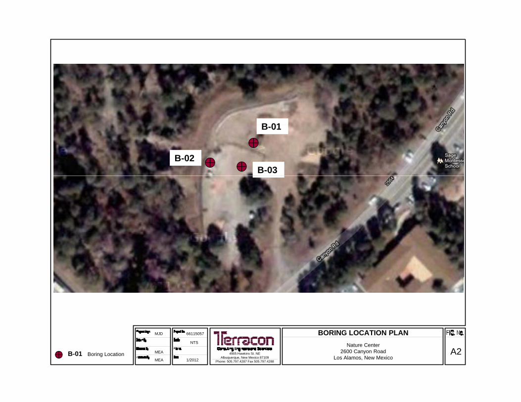
2.0 SUBSURFACE EXPLORATION AND TESTING PROCEDURES A total of three (3) test borings were drilled at the site using a CME-75 truck-mounted drilling rig. Test borings were drilled to a depth of about 26-½ feet below existing site grade at the approximate locations shown on Figure A2, Boring Location Plan. Lithologic logs of the test borings were recorded by a field engineer during the drilling operations. At selected intervals, samples of subsurface materials and penetration tests were taken by driving split-spoon or ring-lined barrel samplers using a 140-pound hammer falling 30 inches. The number of blows required to advance the samplers the last 12 inches, or less if hard materials were present, of an 18-inch sampling interval was recorded as the standard penetration resistance value (N). The samples were sealed in the field and then returned to our laboratory for testing and classification. An automatic SPT hammer was used to advance the split-barrel samplers. The effect of the automatic hammer's efficiency has been considered in our interpretation and analysis. Groundwater measurements were made in the test borings during and at the completion of drilling.
3.0 LABORATORY TESTING PROGRAM Selected soil samples were tested for the following engineering properties:
Gradation Plasticity Index Water Content Dry Density Soluble Sulfate Content Consolidation
As part of the testing program, the soil samples were examined in the laboratory by the field engineer. Based on the material’s texture and plasticity, the soil samples were described and classified in accordance with the attached General Notes and the Unified Soil Classification System, respectively. The estimated group symbols for the Unified Soil Classification System are shown in the appropriate column on the boring logs. A brief description of the Unified System is included in the appendix.
4.0 SUBSURFACE CONDITIONS 4.1 Subsurface Conditions Specific conditions encountered at the boring locations are indicated on the individual boring logs. Stratification boundaries on the boring logs represent the approximate location of changes in soil types; in-situ, the transition between materials may be gradual. Details for the borings can be

Preliminary Geotechnical Engineering Report Nature Center ■ Los Alamos County, New Mexico January 12, 2012 ■ Terracon Project No. 66115057
Reliable ■ Responsive ■ Convenient ■ Innovative 3
found on the attached boring logs. Based on the results of the borings, subsurface conditions on the project site can be generalized as follows:
Description Approximate Depth to
Bottom of Stratum (feet) Material Encountered Consistency/Density
Stratum 1 10 to 22
Fill comprised of silty sand with varying amounts of
gravel, basalt, and asphalt concrete debris.
Loose to Dense
Stratum 3 26-½ Tuff bedrock. Firm to Hard
Samples retrieved during the field exploration were taken to the laboratory for further observation by the project geotechnical engineer and were classified in accordance with the Unified Soil Classification System (USCS) and by the American Association of State Highway and Transportation Officials (AASHTO) classification system. Laboratory tests were conducted on selected soil samples and the test results are presented on the attached laboratory test sheets. Laboratory test results indicate that the surface and near surface fill soils exhibit low compressibility potentials at in-situ moisture contents. The near surface fill soils have a moderate to high potential for compression and a non- tendency for expansion when wetted under typical foundation loads. However, based upon the granular nature and low moisture content of the soils, the tests may reflect some sample disturbance. It is our opinion that the near surface fill soils have a moderate to high tendency for compression/consolidation and a non- tendency for expansion, when elevated in moisture content. When water is added to samples of laboratory compacted near-surface soils, we anticipate that the compacted soils will exhibit low compressive and non- to low expansive potential when subjected to light loading conditions such as those imposed by floor slabs. The in-situ moisture contents of the fill ranged from 3 to 22% and the bedrock ranged from 6 to 16%. Laboratory test results indicate the on-site soils exhibit a soluble sulfate concentration of 73 mg/kg.
5.0 GROUND WATER INFORMATION Groundwater was not observed in the test borings at the time of field exploration, nor when checked upon completion of drilling. These observations represent groundwater conditions at the time of the field exploration and may not be indicative of other times, or at other locations. Groundwater conditions can change with varying seasonal and weather conditions, and other factors.

Preliminary Geotechnical Engineering Report Nature Center ■ Los Alamos County, New Mexico January 12, 2012 ■ Terracon Project No. 66115057
Reliable ■ Responsive ■ Convenient ■ Innovative 4
It is our experience that zones of perched and/or trapped groundwater may also occur at times in the subsurface soils overlying bedrock, on top of the bedrock surface or within permeable fractures in the bedrock materials. The location and amount of perched water is dependent upon several factors, including hydrologic conditions, type of site development, irrigation demands on or adjacent to the site, fluctuations in water features, seasonal and weather conditions. Fluctuations in groundwater levels can best be determined by implementation of a groundwater monitoring plan. Such a plan would include installation of groundwater monitoring wells, and periodic measurement of groundwater levels over a sufficient period of time. The possibility of groundwater fluctuations should be considered when developing design and construction plans for the project.
6.0 PRELIMINARY ANALYSIS AND RECOMMENDATIONS
6.1 Geotechnical Considerations The site appears to be suitable for the proposed construction based upon geotechnical conditions encountered in the test borings. However, existing fill soils were encountered in the borings and will require particular attention during design and construction. The existing fill on the site contained varying amounts of construction debris consisting of asphalt concrete and basalt. Based upon information provided by LAC, there is no documentation regarding the placement of fill materials on the project site. Support of footings, floor slabs, and pavements on or above existing fill soils is discussed in this report. However, even with the recommended construction testing services, there is an inherent risk for the owner that compressible fill or unsuitable material within or buried by the fill will not be discovered. This risk of unforeseen conditions cannot be eliminated without completely removing the existing fill. Based on the data generated as part of the current studies, it is our opinion that the existing fill containing debris is uncontrolled and was not properly placed and compacted. In addition, we recommend that supplemental test pits and borings be performed to better assess the nature and composition of the fill. Based on the geotechnical subsurface exploration, the laboratory test results, and our engineering analyses, the proposed building structures can be supported on a spread footing foundation system bearing on a zone of newly placed engineered fill. In addition, a slab-on-grade floor system supported on a zone of newly placed engineered fill can be used, provided some movement can be tolerated. Existing fill containing debris and loose existing fill should be completely removed and replaced as engineered fill beneath foundations, slabs, and pavements. Partial removal of the existing uncontrolled fill containing debris could be considered beneath pavements, provided that an increase in potential movement and future

Preliminary Geotechnical Engineering Report Nature Center ■ Los Alamos County, New Mexico January 12, 2012 ■ Terracon Project No. 66115057
Reliable ■ Responsive ■ Convenient ■ Innovative 5
maintenance can be tolerated. In addition, a geogrid should be placed if this option is utilized to further reduce potential movement and future maintenance. On-site fill soils should be suitable for use as engineered fill beneath the foundation systems, floor slabs and pavements; however, some moisture conditioning and processing will likely be necessary. In addition, the fill will need to be screened of all debris larger than three (3) inches in diameter. The debris could be reused if properly processed to a maximum size of three (3) inches in diameter and properly blended with on-site or imported soils.
6.2 Corrosivity Laboratory test results indicate the on-site soils exhibit a soluble sulfate concentration of 73 mg/kg. Results of soluble sulfate testing indicate that ASTM Type I/II Portland cement is acceptable for all project concrete on and below grade. Foundation concrete should be designed for low sulfate exposure in accordance with the provisions of the ACI Design Manual, Section 318, Chapter 4.
7.0 EARTHWORK
7.1 Site Preparation Strip and remove existing fill, pavements, debris, soil/debris stockpiles, and other deleterious materials from proposed construction areas. Exposed surfaces should be free of mounds and depressions which could prevent uniform compaction. Evidence of underground facilities and utilities were observed near the project site during the site reconnaissance. Therefore, such features could be encountered during construction. If unexpected fills or underground facilities are encountered, such features should be removed and the excavation thoroughly cleaned prior to backfill placement and/or construction.
7.2 Excavation It is anticipated that shallow excavations for the proposed construction can be accomplished with conventional earthmoving equipment. Excavations penetrating the hard materials or large debris may require the use of more specialized heavy-duty equipment to facilitate break-up and removal. Consideration should be given to obtaining a unit price for difficult excavation in the contract documents for the project. Depending upon depth of excavation and seasonal conditions, groundwater may be encountered in excavations on the site. Pumping from sumps may be utilized to control water within excavations. Based upon the subsurface conditions determined from the geotechnical exploration, subgrade soils exposed during construction are anticipated to be relatively stable. However, elevated

Preliminary Geotechnical Engineering Report Nature Center ■ Los Alamos County, New Mexico January 12, 2012 ■ Terracon Project No. 66115057
Reliable ■ Responsive ■ Convenient ■ Innovative 6
moisture contents were encountered at some boring locations. The stability of the subgrade may be affected by precipitation, repetitive construction traffic or other factors. If unstable conditions develop, workability may be improved by scarifying and drying. Overexcavation of wet zones and replacement with granular materials may be necessary. Use of lime, fly ash, kiln dust, cement or geotextiles could also be considered as a stabilization technique. Laboratory evaluation is recommended to determine the effect of chemical stabilization on subgrade soils prior to construction. Lightweight excavation equipment may be required to reduce subgrade pumping. The individual contractor(s) is responsible for designing and constructing stable, temporary excavations as required to maintain stability of both the excavation sides and bottom. Excavations should be sloped or shored in the interest of safety following local, and federal regulations, including current OSHA excavation and trench safety standards.
8.0 GENERAL COMMENTS Terracon should be retained to provide observation and testing services during grading, excavation, foundation construction and other earth-related construction phases of the project. The preliminary analysis and recommendations presented in this report are based upon the data obtained from the borings performed at the indicated locations and from other information discussed in this report. This report does not reflect variations that may occur between borings, across the site, or due to the modifying effects of construction or weather. The nature and extent of such variations may not become evident until during or after construction. If variations appear, we should be immediately notified so that further evaluation and supplemental recommendations can be provided. The scope of services for this project does not include either specifically or by implication any environmental or biological (e.g., mold, fungi, bacteria) assessment of the site or identification or prevention of pollutants, hazardous materials or conditions. If the owner is concerned about the potential for such contamination or pollution, other studies should be undertaken. This report has been prepared for the exclusive use of our client for specific application to the project discussed and has been prepared in accordance with generally accepted geotechnical engineering practices. No warranties, express or implied, are intended or made. Site safety, excavation support, and dewatering requirements are the responsibility of others. In the event that changes in the nature, design, or location of the project as outlined in this report are planned, the conclusions and recommendations contained in this report shall not be considered valid unless Terracon reviews the changes and either verifies or modifies the conclusions of this report in writing.

Source: USGS 7.5-Minute Topographic Map Edition “Guaje Mountain”, New Mexico, United States, dated 2002.
Project Mngr:
Nature Center 2600 Canyon Road
Los Alamos County, New Mexico
SITE LOCATION MAP
MJDDrawn By:
Checked By:
Approved By:
N/A
MEA
MEA
Project No. 66115057
Scale
File No.
Date:
1” ≈ 1000’
12/2011
4905 Hawkins, NE Albuquerque, New Mexico 87109 505.797.4287 Fax: 505.797.4288
FIG No.
1
APPROXIMATE SITE LOCATION
B 01B-01
B-02B-03
BORING LOCATION PLAN
Nature Center2600 Canyon Road
Los Alamos, New MexicoA24905 Hawkins St. NE
Albuquerque, New Mexico 87109Phone: 505.797.4287 Fax 505.797.4288
66115057
NTS
1/2012
MJD
MEA
MEAB-01 Boring Location

10
26.5
FILL: SILTY SAND with GRAVEL; withasphalt concrete debris, brown to black,loose
BEDROCK: TUFF; grey, medium hard tohard
Boring Terminated at 26.5 Feet.
SS
RS
SS
SS
SS
SS
SM
SM
1
2
3
4
5
6
6
15
42
46
50
32
18
6
18
18
18
18
121
22
12
6
8
7
7
UN
CO
NF
INE
DS
TR
EN
GT
H,
psf
TESTS
DESCRIPTION
Nature Center
The stratification lines represent the approximate boundary lines
SITE
BORING STARTED
CME-75
WL
WL
WL
BORING COMPLETED
APPROVED MEA
MJDFOREMANRIG
12-21-11WD
66115057
Los Alamos CountyCLIENT
LOG OF BORING NO. B-01
JOB #
GR
AP
HIC
LO
G
between soil and rock types: in-situ, the transition may be gradual.
Page 1 of 1
PROJECT
12-21-11
NE
WATER LEVEL OBSERVATIONS, ft
2600 Canyon RoadLos Alamos, NM
SAMPLES
US
CS
SY
MB
OL
WA
TE
RC
ON
TE
NT
, %
TY
PE
NU
MB
ER
5
10
15
20
25
DE
PT
H,
ft.
RE
CO
VE
RY
, in
.
DR
Y U
NIT
WT
pcf
SP
T -
NB
LOW
S /
ft.
BO
RE
HO
LE_9
9 6
611
5057
.GP
J T
ER
RA
CO
N.G
DT
1/
12/1
2

0.4
22
26.5
Approximately 5 inches Asphalt ConcreteFILL: SILTY SAND with GRAVEL; withasphalt concrete and basalt debris, brownto black, medium dense to dense
BEDROCK: TUFF; grey, firm
Boring Terminated at 26.5 Feet.
SS
RS
SS
SS
SS
SS
SM
SM
SM
SM
SM
1
2
3
4
5
6
40
50/0.5
10
13
33
29
16
4
16
16
16
18
96
13
16
11
12
18
12
UN
CO
NF
INE
DS
TR
EN
GT
H,
psf
TESTS
DESCRIPTION
Nature Center
The stratification lines represent the approximate boundary lines
SITE
BORING STARTED
CME-75
WL
WL
WL
BORING COMPLETED
APPROVED MEA
MJDFOREMANRIG
12-21-11WD
66115057
Los Alamos CountyCLIENT
LOG OF BORING NO. B-02
JOB #
GR
AP
HIC
LO
G
between soil and rock types: in-situ, the transition may be gradual.
Page 1 of 1
PROJECT
12-21-11
NE
WATER LEVEL OBSERVATIONS, ft
2600 Canyon RoadLos Alamos, NM
SAMPLES
US
CS
SY
MB
OL
WA
TE
RC
ON
TE
NT
, %
TY
PE
NU
MB
ER
5
10
15
20
25
DE
PT
H,
ft.
RE
CO
VE
RY
, in
.
DR
Y U
NIT
WT
pcf
SP
T -
NB
LOW
S /
ft.
BO
RE
HO
LE_9
9 6
611
5057
.GP
J T
ER
RA
CO
N.G
DT
1/
12/1
2

17.5
26.5
FILL: SILTY SAND with GRAVEL variesto WELL-GRADED GRAVEL with SAND;with asphalt concrete debris, brown toblack, loose to medium dense
BEDROCK: TUFF; grey, firm to mediumhard
Boring Terminated at 26.5 Feet.
SS
RS
SS
SS
SS
SS
SM
GW
SM
SM
1
2
3
4
5
6
6
18
12
4
31
22
16
6
14
14
18
18
104
16
3
13
14
15
16
UN
CO
NF
INE
DS
TR
EN
GT
H,
psf
TESTS
DESCRIPTION
Nature Center
The stratification lines represent the approximate boundary lines
SITE
BORING STARTED
CME-75
WL
WL
WL
BORING COMPLETED
APPROVED MEA
MJDFOREMANRIG
12-21-11WD
66115057
Los Alamos CountyCLIENT
LOG OF BORING NO. B-03
JOB #
GR
AP
HIC
LO
G
between soil and rock types: in-situ, the transition may be gradual.
Page 1 of 1
PROJECT
12-21-11
NE
WATER LEVEL OBSERVATIONS, ft
2600 Canyon RoadLos Alamos, NM
SAMPLES
US
CS
SY
MB
OL
WA
TE
RC
ON
TE
NT
, %
TY
PE
NU
MB
ER
5
10
15
20
25
DE
PT
H,
ft.
RE
CO
VE
RY
, in
.
DR
Y U
NIT
WT
pcf
SP
T -
NB
LOW
S /
ft.
BO
RE
HO
LE_9
9 6
611
5057
.GP
J T
ER
RA
CO
N.G
DT
1/
12/1
2

0
5
10
15
20
25
30
35
40
45
50
55
60
65
70
75
80
85
90
95
100
0.0010.010.1110100
NP
NP
22
NP
NP
31
GRAIN SIZE DISTRIBUTION
10.0ft
2.5ft
5.0ft
10.0ft
2.5ft
5.0ft
65.2
50.4
36.5
%Clay
B-01
B-02
B-03
100 1403 2
COBBLESGRAVEL SAND
SILT OR CLAY
4
B-01
B-02
B-03
14 16 20 30 401.5 3
%Gravel %Sand %Silt
Specimen Identification
Specimen Identification
Classification
5041 3/4 1/23/8
LL PL
GRAIN SIZE IN MILLIMETERS
PE
RC
EN
T F
INE
R B
Y W
EIG
HT
D10
fine coarse medium
6
0.627
1.416
10.171
9.5
25
37.5
0.137
2.77 0.496
200
coarse
D100 D60
6 810
D30
CuPI Cc
20.51
3.3
23.9
62.1
31.4
25.7
1.4
1.52
60
fine
HYDROMETERU.S. SIEVE OPENING IN INCHES U.S. SIEVE NUMBERS
NP
NP
9
SILTY SAND(SM)
SILTY SAND with GRAVEL(SM)
WELL-GRADED GRAVEL with SAND(GW)
Project: Nature CenterSite: 2600 Canyon Road Los Alamos, NMJob #: 66115057Date: 1-12-12T
C_G
RA
IN_S
IZE
661
150
57.G
PJ
TE
RR
AC
ON
.GD
T
1/12
/12

0
1
2
3
4
5
6
7
81 10 100 1,000 10,000
CONSOLIDATION TEST
AX
IAL
ST
RA
IN,
%
PRESSURE, psf
Project: Nature CenterSite: 2600 Canyon Road Los Alamos, NMJob #: 66115057Date: 1-12-12
ClassificationSpecimen Identification , pcf WC,%
Notes: Results may reflect some sample distubance
5.0ft SILTY SAND with GRAVEL (SM) 121 12B-01
TC
_CO
NS
OL_
ST
RA
IN 6
611
5057
.GP
J T
ER
RA
CO
N.G
DT
1/
12/1
2

0
1
2
3
4
5
6
7
81 10 100 1,000 10,000
CONSOLIDATION TEST
AX
IAL
ST
RA
IN,
%
PRESSURE, psf
Project: Nature CenterSite: 2600 Canyon Road Los Alamos, NMJob #: 66115057Date: 1-12-12
ClassificationSpecimen Identification , pcf WC,%
Notes: Results may reflect some sample disturbance
5.0ft SILTY SAND with GRAVEL (SM) 96 16B-02
TC
_CO
NS
OL_
ST
RA
IN 6
611
5057
.GP
J T
ER
RA
CO
N.G
DT
1/
12/1
2

0
1
2
3
4
5
6
7
81 10 100 1,000 10,000
CONSOLIDATION TEST
AX
IAL
ST
RA
IN,
%
PRESSURE, psf
Project: Nature CenterSite: 2600 Canyon Road Los Alamos, NMJob #: 66115057Date: 1-12-12
ClassificationSpecimen Identification , pcf WC,%
Notes: Results may reflect some sample disturbance
5.0ft WELL-GRADED GRAVEL with SAND(GW) 104 3B-03
TC
_CO
NS
OL_
ST
RA
IN 6
611
5057
.GP
J T
ER
RA
CO
N.G
DT
1/
12/1
2

B-01 2.5 22
B-01 5.0 12 120.5
B-01 10.0 NP NP NP 9.5 31 SM 6
B-01 15.0 8
B-01 20.0 7
B-01 25.0 7
B-02 2.5 NP NP NP 25 26 SM 13
B-02 5.0 16 95.6
B-02 10.0 11
B-02 15.0 12
B-02 20.0 18
B-02 25.0 12
B-03 2.5 16
B-03 5.0 31 22 9 37.5 1 GW 3 104.5
B-03 10.0 13
B-03 15.0 14
B-03 20.0 15
B-03 25.0 16
PlasticLimit
PlasticityIndex
MaximumSize(mm)
%<#200Sieve
SUMMARY OF LABORATORY RESULTS
Satur-ation(%)
VoidRatio
Dry UnitWeight
(pcf)
WaterContent
(%)
LiquidLimitBorehole
Sheet 1 of 1
Depthft
USCSClass-
ification
Project: Nature CenterSite: 2600 Canyon Road Los Alamos, NMJob #: 66115057Date: 1-12-12T
C_L
AB
_SU
MM
AR
Y 6
6115
057
.GP
J T
ER
RA
CO
N.G
DT
1/1
2/12


DRILSS: ST: RS: DB: BS:
The pene(RS)fallin
WATWL: WCIDCI:
Watetimesperm DEShaveGraiand accoin-pla
UCo
Stre
1,2,4,
Rev 04
LLING & SAMPSplit SpooThin-WalleRing SamDiamond BBulk Samp
number of bloetration with a 1) the penetrationg 30 inches, re
TER LEVEL MEWater Lev
: Wet Cave Dry Cave
er levels indicas and other loc
meability soils, t
SCRIPTIVE SOe more than 50ned Soils havesilts if they are
ording to the reace relative den
CONSIS
Unconfined ompressive ength, Qu, psf
< 500 500 – 1,000 ,000 – 2,000 ,000 – 4,000 ,000 – 8,000
8,000+
RELATIVE P
Descriptive Tof other cons
TraceWith
Modifie
RELA
Descriptive Tof other cons
TraceWith
Modifie
4/10
PLING SYMBOon - 1-3/8" I.D., 2ed Tube – 2” Opler - 2.42" I.D.Bit Coring - 4", ple or Auger Sa
ows required to140-pound hamon value is repoeported as “blow
EASUREMENTvel in in
ated on the borations across ththe accurate de
OIL CLASSIFIC% of their dry w
e less than 50%e slightly plasticlative proportionsity and fine-g
STENCY OF FI
f
Standard Por N-val
Blow
0 -2 -4 -
8 -15 -
> 3
ROPORTIONS
Term(s) stituents
er
ATIVE PROPO
Term(s) stituents
er
OLS: 2" O.D., unless
O.D., 3" O.D., un., 3" O.D., unlesN, B
ample
o advance a smmer falling 30 orted as the nuws per foot,” an
T SYMBOLS: WWAB
ring logs are thhe site could va
etermination of g
CATION: Soil cweight retained
% of their dry wec or non-plasticns based on g
grained soils on
INE-GRAINED
Penetration lue (SS)
ws/Ft.
- 1 - 4 - 8 - 15 - 30 30
S OF SAND AN
PerDry
15
RTIONS OF F
PerDry
5
GENE
otherwise notenless otherwisess otherwise no
standard 2-inchinches is consi
umber of blowsnd is not conside
S: While SD: While D
B: After Bo
he levels measary. In perviousgroundwater le
classification is on a #200 siev
eight retained oc. Major constitrain size. In ad
n the basis of th
D SOILS
Consistency
Very SoftSoft
Medium StifStiff
Very StiffHard
ND GRAVEL
rcent of y Weight
< 15 5 – 29 ≥ 30
INES
rcent of y Weight
< 5 5 – 12 > 12
RAL NOT
ed e noted oted
h O.D. split-spoidered the “Sta
s required to adered equivalen
Sampling Drilling oring
sured in the bos soils, the indicvels may not b
based on the ve; their principon a #200 sievetuents may be ddition to grada
heir consistency
RE
y Sta
o
ff
Maj
TES
HPAHRW
oon sampler (Sndard Penetrat
dvance the samt to the “Standa
BAN
orings at the timcated levels mae possible with
Unified Soil Clpal descriptors ae; they are prinadded as mod
ation, coarse-gry.
ELATIVE DENS
ndard Penetraor N-value (SS
Blows/Ft.
0 – 3 4 – 9
10 – 29 30 – 50
> 50
GRA
or Componenof Sample Boulders Cobbles Gravel Sand
Silt or Clay
PLA
T
NonL
MeH
S: Hollow A: Power AA: Hand A
RB: Rock BWB Wash B
SS) the last 12tion” or “N-value
mpler 12 inchesard Penetration
CR: Before CR: After C/E: Not Enc
mes indicated. ay reflect the lo only short-term
lassification Syare: boulders, ccipally describe
difiers and minorained soils are
SITY OF COAR
ation S)
AIN SIZE TERM
nt
12 in3 in. to#4 to #
Pass
ASTICITY DESC
Term P
-plastic Low edium High
Stem Auger Auger (Solid St
Auger Bit Boring or Mud R
2 inches of thee”. For 3” O.Ds using a 140-pn” or “N-value”.
Casing Removasing Removalcountered
Groundwater cation of groun
m observations.
ystem. Coarsecobbles, graveled as clays if thor constituents e defined on the
RSE-GRAINED
Relative D
Very LoLoos
Medium DDens
Very De
MINOLOGY
Particle S
Over 12 in. (30. to 3 in. (300m
o #4 sieve (75m#200 sieve (4.75sing #200 Sieve
CRIPTION
Plasticity Index
0 1-10 11-30 > 30
tem)
Rotary
e total 18-inch. ring samplerspound hammer
val l
levels at otherndwater. In low.
Grained Soils or sand. Fine
hey are plastic,may be addede basis of their
D SOILS
Density
oose se Dense se ense
Size
00mm) mm to 75mm) mm to 4.75mm)
5 to 0.075mm)e (0.075mm)
s r
r w
s e
r

Form 111—6/98
UNIFIED SOIL CLASSIFICATION SYSTEM
Criteria for Assigning Group Symbols and Group Names Using Laboratory TestsA Soil Classification
Group Symbol
Group NameB
Coarse Grained Soils
More than 50% retained
on No. 200 sieve
Gravels More than 50% of coarse fraction retained on No. 4 sieve
Clean Gravels Less than 5% finesC
Cu ≥ 4 and 1 ≤ Cc ≤ 3E GW Well-graded gravelF
Cu < 4 and/or 1 > Cc > 3E GP Poorly graded gravelF
Gravels with Fines More than 12% finesC
Fines classify as ML or MH GM Silty gravelF,G, H
Fines classify as CL or CH GC Clayey gravelF,G,H
Sands 50% or more of coarse fraction passes No. 4 sieve
Clean Sands Less than 5% finesD
Cu ≥ 6 and 1 ≤ Cc ≤ 3E SW Well-graded sandI
Cu < 6 and/or 1 > Cc > 3E SP Poorly graded sandI
Sands with Fines More than 12% finesD
Fines classify as ML or MH SM Silty sandG,H,I
Fines Classify as CL or CH SC Clayey sandG,H,I
Fine-Grained Soils 50% or more passes the No. 200 sieve
Silts and Clays Liquid limit less than 50
inorganic PI > 7 and plots on or above “A” lineJ CL Lean clayK,L,M
PI < 4 or plots below “A” lineJ ML SiltK,L,M
organic Liquid limit - oven dried < 0.75 OL
Organic clayK,L,M,N
Liquid limit - not dried Organic siltK,L,M,O
Silts and Clays Liquid limit 50 or more
inorganic PI plots on or above “A” line CH Fat clayK,L,M
PI plots below “A” line MH Elastic SiltK,L,M
organic Liquid limit - oven dried < 0.75 OH
Organic clayK,L,M,P
Liquid limit - not dried Organic siltK,L,M,Q
Highly organic soils Primarily organic matter, dark in color, and organic odor PT Peat
A Based on the material passing the 3-in. (75-mm) sieve B If field sample contained cobbles or boulders, or both, add “with cobbles
or boulders, or both” to group name. C Gravels with 5 to 12% fines require dual symbols: GW-GM well-graded
gravel with silt, GW-GC well-graded gravel with clay, GP-GM poorly graded gravel with silt, GP-GC poorly graded gravel with clay.
D Sands with 5 to 12% fines require dual symbols: SW-SM well-graded sand with silt, SW-SC well-graded sand with clay, SP-SM poorly graded sand with silt, SP-SC poorly graded sand with clay
E Cu = D60/D10 Cc = 6010
230
DxD
)(D
F If soil contains ≥ 15% sand, add “with sand” to group name. G If fines classify as CL-ML, use dual symbol GC-GM, or SC-SM.
HIf fines are organic, add “with organic fines” to group name. I If soil contains ≥ 15% gravel, add “with gravel” to group name. J If Atterberg limits plot in shaded area, soil is a CL-ML, silty clay. K If soil contains 15 to 29% plus No. 200, add “with sand” or “with
gravel,” whichever is predominant. L If soil contains ≥ 30% plus No. 200 predominantly sand, add
“sandy” to group name. M If soil contains ≥ 30% plus No. 200, predominantly gravel, add
“gravelly” to group name. N PI ≥ 4 and plots on or above “A” line. O PI < 4 or plots below “A” line. P PI plots on or above “A” line. Q PI plots below “A” line.