Embed Size (px)
Citation preview

CAPACITANCE
TRANSIENTS IN CAPACITIVE NETWORKS:THE CHARGING PHASE; THE DISCHARGING PHASETHÉVENIN EQUIVALENT: T RThC
THE CURRENT iC
CAPACITORS IN SERIES AND IN PARALLEL
ENERGY STORED BY A CAPACITOR
CAPACITOR AND INDUCTOR
INDUCTANCE
R-L TRANSIENTS: THE STORAGE PHASE, THE RELEASE PHASE
INDUCTORS IN SERIES AND IN PARALLEL
INDUCED VOLTAGE YL
ENERGY STORED BY AN INDUCTOR

CAPACITANCE Capacitance is a measure of a capacitor’s ability to store charge on itsplates—in other words, its storage capacity.
The higher the capacitance of a capacitor, the greater the amount of charge stored on the plates for the same applied voltage.
A capacitor has a capacitance of 1 F if 1 C of charge is deposited on the plates by a potential difference of 1 V across its plates
The electric field strength between the plates is determined by thevoltage across the plates and the distance between the plates

The capacitance of a capacitor with a dielectric having a relative permittivity of r is r times the capacitance using air as the dielectric.
The general equation for capacitance (a)electrolytic
(b) polyester-film
(c) tantalum

TRANSIENTS IN CAPACITIVE NETWORKS:THE CHARGING PHASE
The period of time during which charge is being
deposited on the plates is called the transient
period—a period
of time where the voltage or current changes from
one steady-state level to another.
The phase during which charge is deposited on the plates
Since the voltage across the plates is directly
related to the charge on the plates by VQ/C, a plot
of the voltage across the capacitor will have the
same shape as a plot of the charge on the plates
over time

The factor τ, called the time constant of the network, has the units of time
The equation for the current is:
The current of a capacitive dc network is essentially zero amperes after five time constants of the charging phase have passed.

During the charging phase, the major change in voltage and current occurs during the first time constant.
A capacitor can be replaced by an open-
circuit equivalent once the charging
phase in a dc network has passed.
The voltage across a capacitor cannot change instantaneously
A capacitor has the characteristics of a short-circuit equivalent at the instant the switch is
closed in an uncharged series R-C circuit.

TRANSIENTS IN CAPACITIVE NETWORKS:THE DISCHARGING PHASE
The voltage across the capacitor that is decreasing with time
The time constant τ
The current decreases with time
since vR vC (in parallel), the equation for the voltage vR

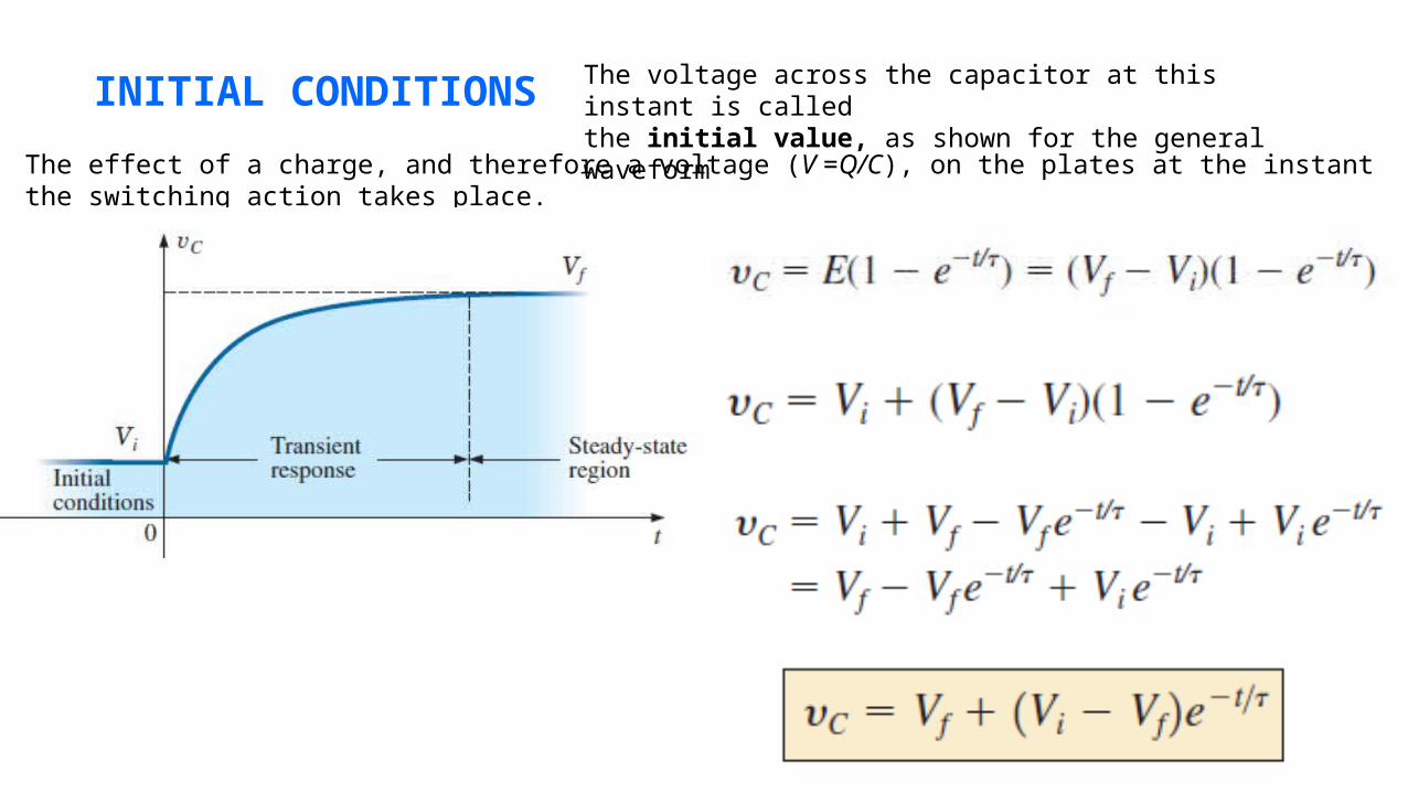
INITIAL CONDITIONS The voltage across the capacitor at this instant is calledthe initial value, as shown for the general waveformThe effect of a charge, and therefore a voltage (V =Q/C), on the plates at the instant the switching
action takes place.

a. Find the mathematical expression for the voltage
cross the capacitor once the switch is closed.b. Find the mathematical expression for the current during the transient period.
THE CURRENT iCThe capacitive current is directly related to the rate of change of thevoltage across the capacitor, not the levels of voltage involved.
The factor C reveals that the higher the capacitance, the greater the resulting current

CAPACITORS IN SERIES AND IN PARALLELFor capacitors in series, the charge is the same on each capacitor
Applying Kirchhoff’s voltage law around the closed loop gives
dividing both sides by Q yields
The total capacitance of two capacitors in series is
The voltage across each capacitor

CAPACITORS IN PARALLEL,
The voltage is the same across each capacitor, and the
total charge is the sum of that on each capacitor:

a. Find the total capacitance.b. Determine the charge on each plate.c. Find the total charge

ENERGY STORED BY A CAPACITOR
An ideal capacitor does not dissipate any of the energy supplied to it. It stores the energy in the form
of an electric field between the conducting surfaces.
The energy stored is represented by the shaded area under the power curve

INDUCTANCE
1 henry is the inductance level that will establish a voltage of 1 volt across the coil due to a
change in current of 1 A/s through the coil.
𝝁=𝝁𝒓×𝝁𝒐
The inductance of an inductor with a ferromagnetic core is μr times the inductance obtained with an air core.

INDUCED VOLTAGE VL
The larger the inductance and/or the more rapid the change in current through a coil, the
larger will be the induced voltage across the coil.
An induced effect is always such as to oppose the cause that produced it.

R-L TRANSIENTS: THE STORAGE PHASEThe equation for the transient response of the current through an inductor is
The time constant
The equation for the voltage across the coil is
The voltage across the resistor

The current cannot change instantaneously in an inductive network.The inductor takes on the characteristics of an open circuit at the instant the switch is closedThe inductor takes on the characteristics of a short circuit when steady-state conditions have been established
INITIAL CONDITIONS

Find the mathematical expressions for the transient behavior of iL and VL for the circuit, if the switch is closed at t= 0 s.

R-L TRANSIENTS: THE RELEASE PHASE
In R-L circuits, the energy is stored in the form of a
magnetic field established by the current through
the coil
An isolated inductor cannot continue to store
energy, because the absence of a closed path
causes the current to drop to zero, releasing the
energy stored in the form of a magnetic field.
If the series R-L circuit reaches steady-state conditions and the switch is quickly opened, a spark will
occur across the contacts due to the rapid change in current from a maximum of E/R to zero amperes.
The change in current di/dt of the equation VL =L(di/dt) establishes a high voltage VL across the coil that,
in conjunction with the applied voltage E, appears across the points of the switch.

When the switch is closed, the voltage across resistor R2 is E volts, and the R-L branch responds in
the same waveforms and levels. A Thévenin network of E in parallel with R2 results in the source as
shown in above figure, since R2 will be shorted out by the short-circuit replacement of the voltage
source E when the Thévenin resistance is determined.

After the storage phase has passed and steady-state
conditions are established, the switch can be opened
without the sparking effect or rapid discharge due to
resistor R2, which provides a complete path for the current
iL. In fact, for clarity the discharge path is isolated. The
voltage VL across the inductor reverses polarity and has a
magnitude determined by
The voltage across an inductor can change instantaneously but the current cannot. That is the current
iL must maintain the same direction and magnitude

When the switch is opened, the voltage across the inductor reverses polarity and drops
instantaneously from E to
- [1+(R2/R1)]E volts.As an inductor releases its stored energy, the voltage across the coil decays to zero in the following manner
The current decays from a maximum of to zero

The voltage across either resistor can then be determined using ohm’s law:
The voltage has the same polarity as during the storage phase since the current iL has the same
direction. The voltage is expressed as follows
If the switch is opened before il reaches its maximum value, the equation for the decaying current must change to
where Ii is the starting or initial current. The voltage across the coil is

INDUCTORS IN SERIES AND IN PARALLEL
For inductors in series, the total inductance is found in the same manner as the total resistance of resistors in series
For inductors in parallel, the total inductance is found in the same manner as the total resistance of resistors in parallel

ENERGY STORED BY AN INDUCTOR
The ideal inductor, like the ideal capacitor, does not dissipate the electrical energy supplied to it. It stores the energy in the form of a magnetic field
The energy stored is represented by the shaded area under the power curve.

Find the energy stored by the inductor in the circuit, when the current through it has reached its final value