Embed Size (px)
Citation preview

PART I
Cache
So, we can never reach a Final Understanding of anything because it will change as we develop understanding. If we did reach a Final Understanding, simultaneously the “subject” would have changed, rendering our understanding as past tense … .
— Robert Fripp
ch01_P379751.indd Sec2:55ch01_P379751.indd Sec2:55 8/7/07 9:00:27 PM8/7/07 9:00:27 PM

ch01_P379751.indd Sec2:56ch01_P379751.indd Sec2:56 8/7/07 9:00:28 PM8/7/07 9:00:28 PM

57
CHAPTER 1
A cache (also called “look-aside” [Bloom et al. 1962] or “slave memory” [Wilkes 1965]) can speed up accesses to all manners of storage devices, includ-ing tape drives, disk drives, main memory, servers on the network (e.g., web servers are a type of storage device), and even other caches. It works on the prin-ciple of locality of reference, the tendency of applica-tions to reference a predictably small amount of data within a given window of time [Belady 1966, Denning 1970]. Any storage device can be characterized by its access time and cost per bit, where faster storage technologies tend to have a lower access time and cost more per bit than slower technologies. A cache fronting a given storage device would be built from a technology that is faster than that of the storage device in question; the cache technology would typi-cally cost more on a per-bit basis, but to be effective the cache would only need to be large enough to hold the application’s working set—the set of instructions and/or data items the application is currently using to perform its computations [Denning 1967]. Due to locality of reference, most of the application accesses will be satisfi ed out of the cache, and so most of the time the access characteristics will be that of the cache: far faster and often consuming less energy than the larger storage device behind the cache.
As far as implementation technologies, caches can be built of anything that holds state. Hardware caches are used widely in computer systems (SRAM can act as a cache for DRAM; DRAM can act as a cache for disk; fast DRAM can act as a cache for slow DRAM; disk can act as a cache for tape; etc.), and software caches abound as well (the operating sys-tem caches disk blocks and network addresses; web proxies cache popular web-based documents; even
hardware devices such as disk drives cache data locally, implementing the cache algorithm in software executing on a control processor). In addition, what is logically a single cache may, in fact, be comprised of many distinct entities that operate in concert. For instance, the separate last-level caches belonging to the different processors in a symmetric multiproces-sor can be thought of (and even managed) as a dis-tributed but logically monolithic entity. Conversely, some cache organizations described as a single cache are, in fact, multi-level hierarchies [Kim et al. 2002]. Neither of these scenarios are erroneous or should be taken as misleading. Any set of multiple storage units can be labeled and analyzed as a single “cache,” and any monolithic cache can be labeled and analyzed as a set of multiple, independent entities. The choice of how to portray a particular cache is often made out of necessity (e.g., to make an algorithm feasible, as in Wheeler and Bershad’s treatment of a single cache as a collection of logically independent partitions [1992]) or out of convenience (e.g., to simplify an explanation, as in Kim’s NUCA [Non-Uniform Cache Architecture]). The bottom line is that the term cache means many things to many different fi elds of dis-cipline, and rather than treat some uses as “correct” and others as “incorrect,” we consider it quite use-ful to develop a framework that encompasses most, if not all, uses of the term. The primary contribution of Part I of the book is the presentation of just such a framework.
Caches can be transparent, meaning that they work independently of the client making the request (e.g., the application software executing on the com-puter) and therefore have built-in heuristics that determine what data to retain. Caches can also be
An Overview of Cache Principles
ch01_P379751.indd Sec2:57ch01_P379751.indd Sec2:57 8/7/07 9:00:28 PM8/7/07 9:00:28 PM

58 Memory Systems: Cache, DRAM, Disk
managed explicitly by the client making the request (these are often called scratch-pads) or can represent some hybrid of the two extremes. Examples of trans-parent caches include the processor caches found in general-purpose systems, the fi le caches found in most distributed fi le systems, and nearly all forms of web cache given that the “client” of a web cache is typically the person using the web browser. Exam-ples of scratch-pads include the ubiquitous register fi le as well as the tagless SRAMs found in nearly all microcontrollers and digital signal processors. The former (transparent cache) operates autonomously with respect to the client; the cached version can be deleted, lost, or invalidated, and the original is still available in the backing store. The latter (scratch-pad) requires the direct control of the client to move data in and out; working with the cached version of a datum means one is, in fact, working with the only version—the cache is not autonomous and therefore makes no attempt to propagate changes back to the original.
Hybrid caches incorporate aspects of both auton-omy and client-directed management. Examples include Cheriton’s software-controlled caches in the VMP multiprocessor system [Cheriton et al. 1986, 1988, 1989], as well as modern “snarfi ng” caches found in many commercial multiprocessors. A slightly different hybrid example is the operating system’s buffer cache, a section of main memory that is man-aged by the operating system to store disk blocks. The software that manages the buffer cache operates independently of application software, but the buf-fer cache can also serve the operating system itself, i.e., the operating system can be a client of the buffer cache, just like application software, and in this case there is no distinction between the manager of the cache and the client of the cache, just like a software-managed cache or a scratch-pad memory.
The reason it is important to identify who or what is responsible for managing the cache contents is that, if given little direct input from the running application, a cache must infer the application’s intent, i.e., it must attempt to predict the future behavior of the client (e.g., the application currently executing). Thus, the cache’s heuristics for deciding what to retain, when to retain it, where to store it, and when to get rid of it are
extremely important. The heuristics for a transparent cache, which are embodied in its organization and various fetch, eviction, and placement strategies, fundamentally determine the cache’s effectiveness. By contrast, purely client-managed caches incor-porate no cache-based heuristics whatsoever. For example, solid-state caches managed by application software embody no hardware-based heuristics at all; the cache’s effectiveness is determined entirely by choices made by the application itself.
This leads us to the three primary components of our framework. Every cache, whether implemented in hardware or software, whether transparent or client managed, whether distributed or monolithic, embod-ies instances of the following three items:
The cache’s organization is the logical arrangement of data stored within its con-text. For example, an operating system’s buffer cache could be organized as an array of queues, with each queue loosely repre-senting the last time a stored object was referenced (e.g., queue1 holds items just arrived, queue2 holds items recently refer-enced, queue3 holds items not referenced in a while, etc.); a solid-state cache could be organized as an array of sets, each of which contains a handful of cache blocks main-tained in a time-ordered manner. Content-management heuristics repre-sent the decision to cache or not to cache a particular item at a particular time during execution. These can be implemented either at design time by the programmer and/or compiler—or at run time by application software and/or the cache itself. The heuris-tics can be static in nature, in which case the cache’s contents do not change signifi cantly over time, or dynamic in nature, in which case the cache’s contents could change radi-cally from moment to moment. Consistency-management heuristics ensure that the instructions and data that application software expects to receive are the ones the software does, indeed, receive. Like cache contents, consistency can be managed by any of several different
•
•
•
ch01_P379751.indd Sec2:58ch01_P379751.indd Sec2:58 8/7/07 9:00:28 PM8/7/07 9:00:28 PM

Chapter 1 AN OVERVIEW OF CACHE PRINCIPLES 59
entities, including the operating system, the application software, or the cache itself.
These components appear in every cache, and they are present even if not explicitly chosen or imple-mented. For example, a simple array of blocks is an organization. Even fetch-nothing can be considered a simple, if ineffectual, content-management heuris-tic; and, similarly, having no consistency heuristic at all is still a design choice. At fi rst glance, these mecha-nisms are all independent; they are largely orthogonal in that the choice made for one component typically does not restrict signifi cantly a designer’s available choices for the other components. For instance, one can freely change cache size and associativity simul-taneously with the prefetch and write-back policies and also simultaneously with the choice of cache-coherence protocol. Upon deeper inspection, how-ever, many of the issues are heavily interconnected: choices made for one component can make the problems easier or harder to solve for other compo-nents. For example, the use of a virtual cache orga-nization places an enormous burden on consistency management that is not present with physical caches (for more detail, see Chapter 4, Section 4.2.1, “Virtual Cache Management).
For further in-depth reading on the topic of trans-parent processor caches, we suggest as starting points the thorough discussion by Hennessy and Patterson [2003] and Alan J. Smith’s excellent survey [1982], which is as pertinent today as it was when it was writ-ten (i.e., don’t let the publication date fool you). For further reading on both hardware and software tech-niques for scratch-pad memories specifi cally and embedded memory systems generally, we suggest as a starting point the inaugural, two-part issue of ACM Transactions on Embedded Computing Systems [Jacob & Bhattacharyya 2002].
1.1 Caches, ‘Caches,’ and “Caches” Nearly every fi eld imaginable, or at least every fi eld
that deals with data in some form or another, has adapted the concept of cache, and every fi eld uses the same term (i.e., cache) to describe what it is that they
have built. For example, the digital signal processor (DSP) community uses the word cache to describe the dual SRAM scratch-pads found on DSP chips that enable simultaneous access to two data operands [Lapsley et al. 1997], and the high- performance com-puting community uses the same word to describe the largely autonomous and increasingly complex processor caches that are completely transparent to software and resemble small hardware databases more than anything else. These are both built-in hardware. Software caches are just as prevalent: the world-wide web uses fi le caching extensively in web proxies [Luotonen & Altis 1994]; network routers cache domain name system (DNS) entries to speed translation from domain names to Internet Protocol (IP) addresses; the operating system stores disk data in its buffer cache (an in-memory cache of disk buf-fers) to reduce the time spent going to the disk sys-tem; and even the disk itself caches buffers in its own local storage.
This is illustrated in Figure 1.1, which shows numerous different caches. The top row presents var-ious confi gurations of solid-state hardware caches, and the bottom row presents examples of software caches.
Figure 1.1(a) shows a general-purpose core with its cache. The cache is transparent in that the software executing on the core makes what it believes to be a request to the backing store (the DRAM behind the cache), and the cache intercepts the request. This requires the cache to be aware of its own contents so it can determine if the requested data is stored locally or not.Figure 1.1(b) shows another confi guration of a general-purpose cache, in which the cache is logically and/or physically split into two separate partitions: one that holds only instructions and one that holds only data. Partitioning caches can improve behav-ior. For instance, providing a separate bus to each partition potentially doubles the bandwidth to the cache, and devoting one partition to fi xed-length instructions can simplify read-out logic by obviating support for variable-sized reads.
•
•
ch01_P379751.indd Sec2:59ch01_P379751.indd Sec2:59 8/7/07 9:00:29 PM8/7/07 9:00:29 PM

60 Memory Systems: Cache, DRAM, Disk
Figure 1.1(c) shows another partitioned confi guration, one that is found in most DSP architectures. As we will discuss in more detail later, these caches are an extension of the memory space, and, unlike the previous two organizations, they are not transparent to software. The main item to note is that the two partitions both hold data. This con-fi guration is desirable in DSPs because of the high data bandwidth required by many DSP algorithms (e.g., dot-product calcula-tions such as fi nite impulse response [FIR] fi lters), which fetch two different data oper-ands from memory on every cycle.Figure 1.1(d) shows a typical cache hierar-chy for a multiprocessor organization. Each
•
•
processor core has its own private cache, and the last-level cache before the backing store (DRAM) is shared by all cores.Figure 1.1(e) shows two different types of caches. First, the operating system stores the blocks it has fetched from disk in main memory as part of a buffer cache. When an application reads and writes data from/to fi les on disk, those requests are not serviced by the disk directly but are instead serviced out of the buffer cache. In addition, modern disks implement their own caches as well; these caches are not under the control of the operating system, but instead operate autonomously. We discuss disk caches in more detail in Chapter 22.
•
CPU
Cache
DRAM
CPU
DRAM
I-Cache D-Cache
CPU
DRAM
Cache 0 Cache 1
CPU
Cache
CPU
Cache
CPU
Cache
Cache (L2)
DRAM
(d) multi-level cache hierarchy
BrowserBrowserBrowser
Cache Cache Cache
Cache
WebServer
Web proxy
SOLID-STATE (HARDWARE) CACHES
SOFTWARE CACHES
Cache
DNSServer
Operating System
Buffer Cache
Operating System
Cache
Hard Disk
Cache
Hard Disk
(g) web-document caches(f) IP-address translation caches(e) buffer caches (on both sides of interface)
(a) general-purpose cache (b) split cache (gen-purpose) (c) DSP-style caches
FIGURE 1.1: Examples of caches. The caches are divided into two main groups: solid-state caches (top), and those that are implemented by software mechanisms, typically storing the cached data in main memory (e.g., DRAM) or disk.
ch01_P379751.indd Sec2:60ch01_P379751.indd Sec2:60 8/7/07 9:00:29 PM8/7/07 9:00:29 PM

Chapter 1 AN OVERVIEW OF CACHE PRINCIPLES 61
Figure 1.1(f) shows another cache maintained by the operating system. When a translation is needed from domain name to IP address, the operating system may or may not actually ask a DNS server directly. Translations may be cached locally to avoid network requests. Similarly, routing information for hosts and subnets is typically cached locally.Figure 1.1(g) shows two different types of caches. First, each web browser typically maintains its own local cache of down-loaded web documents. These documents are usually stored on the local disk and buff-ered in main memory as part of the operat-ing system’s buffer cache (Figure 1.1(e)). In addition, a request that is sent to a particu-lar web server may or may not actually reach the web server. A web proxy, which behaves like the transparent caches in Figures 1.1(a), (b), and (d), may intercept the request and reply on behalf of the server [Luotonen & Altis 1994].
One of the most important distinctions between different types of cache is their method of address-ing. Some caches do not hold a copy of a datum; they hold the datum itself. These are often called scratch-pad memory and use a separate namespace from the backing store (i.e., the primary memory). A scratch-pad is non-transparent in that a program addresses it explicitly. A datum is brought into the scratch-pad by an explicit move that does not destroy the original copy. Therefore, two equal ver-sions of the data remain; there is no attempt by the hardware to keep the versions consistent (to ensure that they always have the same value) because the semantics of the mechanism suggest that the two copies are not, in fact, copies of the same datum, but are instead two independent data. If they are to remain consistent, it is up to software. By con-trast, the typical general-purpose cache uses the same namespace as the primary memory system. It is transparent in that a program addresses main
•
•
memory to access the cache—a program does not explicitly access the cache or even need to know that the cache exists.
How each of these two mechanisms (transparent cache and scratch-pad memory) fi ts into the micropro-cessor’s memory model is shown in Figure 1.2, using solid-state memories (processor caches and tagless SRAMs) for examples. A general-purpose memory model has a single namespace1 that is shared by all memory structures. Any datum from any part of the namespace can be found in any of the caches. By contrast, a scratch-pad uses the namespace to directly address the caches. For instance, the DSP memory model shown on the right explicitly places the system’s memory structures at specifi c disjunct locations in the namespace. A particu-lar address corresponds to a particular physical storage device, and unlike a transparently addressed cache, a single address in the scratch-pad’s namespace cannot refer to both a cached datum and its copy in the back-ing store.
1Assumes physically indexed caches.
UNIFORMADDRESS
SPACE
NON-UNIFORMADDRESS
SPACE
I-CACHE
D-CACHE
SRAM0
SRAM1
DRAM
IBUF
FIGURE 1.2: Transparent caches in a uniform space versus scratch-pad SRAMs in a non-uniform space. Any datum in the memory space can also reside in a cache (thus the designation “transparent”). Only items in certain segments of the memory space can reside in a scratch-pad memory.
ch01_P379751.indd Sec2:61ch01_P379751.indd Sec2:61 8/7/07 9:00:30 PM8/7/07 9:00:30 PM

62 Memory Systems: Cache, DRAM, Disk
As mentioned earlier, what one terms a single cache, or what one terms a set of multiple indepen-dent caches, is entirely a matter of convenience and/or need. For instance, the caches in Figure 1.1(b) can be labeled and analyzed as a single cache. One can always analyze the multiple caches at the same “level” in the hierarchy as a single unit (e.g., the L1 caches in Figure 1.1(d), the disk caches in Figure 1.1(e), or the browser caches in Figure 1.1(g)), even though they operate independently. Similarly, one can group the caches in Figures 1.1(d), (e), and (g), which all incor-porate entire hierarchies. Depending on the analysis, it may be convenient to treat all levels of cache as a single entity separate from the backing store, but not separate from each other. Going the other way, it is just as correct to treat what appears to be a single cache as a set of independent units. For instance, the caches in Figures 1.1(a) and (f) could each be treated as a collection of independently analyzed blocks.
Finally, embracing all of these different mecha-nisms as caches, as different aspects of the same thing, enables the solutions developed in different fi elds of study to cross-pollinate. The goal and point of the formalism, which is presented in detail in the following chapters, are to enable such an analysis. First, the remainder of this chapter presents many of the underlying principles that are common to the caches found across disciplines.
1.2 Locality PrinciplesOver the decades that the computer has been used
and studied, computer engineers have measured program behavior and have made the following observations:
The memory-access patterns of programs are not random.Accesses tend to repeat themselves in time and/or be near each other in the memory address space.
•
•
An important note is that these are not guarantees, they are merely observations. The implication of their being observations, as opposed to provably inherent behaviors, is that, unless we can show that new pro-gram behaviors will never appear, we need to continue measuring and observing programs and should expect to discover new behaviors occasionally.
As mentioned in the Overview chapter, the phe-nomenon of exhibiting predictable, non-random memory-access behavior is called locality of reference. The behavior is so named2 because we have observed that a program’s memory references tend to be local-ized in time and space:
If the program references a datum once, it is likely in the near future to reference that datum again.If the program references a datum once, it is likely in the near future to reference nearby data as well.
The fi rst of these phenomena is called temporal locality, and the second is called spatial locality.
This begs the question: is there nothing else? We have “temporal” and “spatial” aspects of locality. These are brilliantly chosen terms because they imply com-pleteness: time and space cover all possibilities, giving one the distinct if, perhaps, subconscious impression that no other form of locality could possibly exist. It may come as a surprise to some readers that this impression would be wrong.
Remember that these phenomena, these aspects of locality that programs exhibit, are merely observa-tions. They are not inherent to programs, and there is no reason to believe that they are required attributes of a particular program or that they perfectly describe every program that exists. They are merely descrip-tions of the way that most observed programs tend to behave. Lately, computer engineers have observed a new type of phenomenon.
In the past decade, another class of behavior has sprung up, a consequence of the widespread use of
•
•
2The term “locality” was put forth by Belady [1966] and was later formalized, in terms of the working set model, by Denning [1970].
ch01_P379751.indd Sec2:62ch01_P379751.indd Sec2:62 8/7/07 9:00:31 PM8/7/07 9:00:31 PM

Chapter 1 AN OVERVIEW OF CACHE PRINCIPLES 63
computer graphics algorithms and similar algorithms in other domains, including computer simulation, circuit emulation, interpretation of HDL3 code, etc. These programs typically walk down dynamic data structures and access the same data in the same order time and time again (e.g., walking through the com-ponents of a 3D scene each time a new video frame is created), so their behavior is inherently predictable. However, the time between two successive accesses to the same data is large (thus, the program exhibits no signifi cant temporal locality), and the data objects are generally nowhere near each other in the memory space (thus, the program exhibits no signifi cant spatial locality). According to our existing defi nitions of local-ity, these programs exhibit no signifi cant locality,4 but, nonetheless, the programs of this type exhibit regular, predictable, exploitable behavior. It is hard to catego-rize this type of behavior because, between time and space, we seem to have everything covered. So it is easy to overlook the fact that this behavior even exists. But exist it clearly does, even if we have no term for it and even if our naming continuum seems to allow no room for a new term to exist.
For lack of a better term, we will call this behavior algorithmic locality.
The following sections describe these phenomena in more detail.
1.2.1 Temporal LocalityTemporal locality is the tendency of programs to
use data items over and again during the course of their execution. This is the founding principle behind caches and gives a clear guide to an appropriate data-management heuristic. If a program uses an instruc-tion or data variable, it is probably a good idea to keep that instruction or data item nearby in case the program wants it again in the near future.
One corresponding data-management policy or heuristic that exploits this type of locality is demand-
fetch. In this policy, when the program demands (references) an instruction or data item, the cache hardware or software fetches the item from memory and retains it in the cache. The policy is easily imple-mented in hardware. As a side effect of bringing any data (either instructions or program variables and constants) into the processor core from memory, a copy of that data is stored into the cache. Before look-ing to memory for a particular data item, the cache is searched for a local copy.
The only real limitation in exploiting this form of locality is cache storage size. If the cache is large enough, no data item ever need be fetched from the backing store or written to the backing store more than once. Note that the backing store is the term for the level of storage beneath the cache, whether that level is main memory, the disk system, or another level of cache. The term can also be used to mean, collec-tively, the remainder of the memory hierarchy below the cache level in question.
1.2.2 Spatial LocalitySpatial locality arises because of the tendency of
programmers and compilers to cluster related objects together in the memory space. As a result of this, and also because of the human-like way that programs tend to work on related data items one right after the other, memory references within a narrow range of time tend to be clustered together in the memory space. The classic example of this behavior is array processing, in which the elements of an array are pro-cessed one right after the other: elements i and i+1 are adjacent in the memory space, and element i+1 is usually processed immediately after element i.
This behavior, like temporal locality, also points to an obvious data-management policy, typically called lookahead: when instruction i or data item i is requested by the program, that datum should be brought into the processor core and, in addition,
3HDLs are Hardware Description Languages such as Verilog or VHDL, which are commonly used in the specification and design of computer circuits and systems.4Another way of looking at this is that the programs exhibit temporal and/or spatial locality on scales so large that the terms become meaningless.
ch01_P379751.indd Sec2:63ch01_P379751.indd Sec2:63 8/7/07 9:00:31 PM8/7/07 9:00:31 PM

64 Memory Systems: Cache, DRAM, Disk
instruction or data item i+1 should be brought in as well. The simplest form of this policy is to choose judiciously the data-access granularity: to build caches in atomic units called cache blocks that are larger than a single data item. For example, a proces-sor in which the fundamental data unit is a 4-byte word might use a 16-byte cache block containing 4 data words, or a 32-byte cache block containing 8 data words, and so on. Because the cache block is atomic (meaning that this is the granularity of data access between the cache and memory—the amount of data that is moved for every5 read or write), a program’s request for a single data item will result in the surrounding data items all being fetched from memory as a matter of course.
The use of a cache block that is larger than a single data word is very effective, leads to a simple implementation, and can be thought of as a pas-sive form of exploiting spatial locality. Another very effective way to exploit spatial locality is prefetching, which, by comparison, is an active form. Prefetch-ing (which can be done in hardware, software, or a combination of the two) is a mechanism in which the program’s request for an instruction or data item causes more data than just the requested cache block to be fetched from memory. An algorithm uses the memory address with the associated recent history of requested addresses to speculate on which cache block or cache blocks might be used next. An obvious hardware algorithm would be something like fetch-next-block, called one-block lookahead prefetching [Smith 1982], which can be seen as a simple exten-sion of the cache block granularity of access. An obvious software algorithm would be something like fetch-next-array-element, which cannot be per-formed in hardware alone because it requires infor-mation about the size of each data element. Much more sophisticated (and complex) algorithms have been explored as well.
The limit on exploiting this type of locality is due to program behavior and the algorithm’s accuracy of
prediction. If the program tends to access instructions and data in a largely sequential manner, then a simple mechanism is all that is necessary, and the perfor-mance results can be extremely good. If the program behavior is more complex (say, for example, the pro-gram jumps around from cache block to cache block, but in a predictable manner), a static algorithm will not be capable of adapting and will therefore do poorly. In this case, a more sophisticated prefetching algorithm might be able to track program behavior and correctly predict which block to fetch next.
1.2.3 Algorithmic LocalityThe last discussion leads us into algorithmic local-
ity. Algorithmic locality arises when a program repeat-edly accesses data items or executes code blocks that are distributed widely across the memory space. The net result is program behavior that tends to be predictable, but, nonetheless, cannot be captured by using granularity of access or simple lookahead-prefetching mechanisms because the data items ref-erenced by the program are nowhere near each other. Similarly, this behavior cannot be captured by simply increasing the cache size by a factor of two or three because the data and code sizes involved are typically very large.
Many applications that exhibit this aspect of local-ity perform repeated operations on very large data sets that are stored in dynamic data structures that do not change shape radically over short periods of time. Example applications of this sort include graphics pro-cessing, computer simulation, circuit emulation, and various forms of HDL processing (interpretation, syn-thesis, validation, verifi cation, rule-checking, regres-sion testing, etc.).
Many of the steps in 3D computer-graphics pro-cessing fi nd the program repeatedly traversing a large dynamic data structure representing the shape of the physical object being rendered. One example is the Z-buffer algorithm, in which the depth of each object
5However, there are always exceptions (see “Other Policies and Strategies for Transparent (Processor) Caches” in Section 3.1).
ch01_P379751.indd Sec2:64ch01_P379751.indd Sec2:64 8/7/07 9:00:31 PM8/7/07 9:00:31 PM

Chapter 1 AN OVERVIEW OF CACHE PRINCIPLES 65
in the 3D scene is used to paint the two-dimensional (2D) image of the scene:
for each polygon P in scene { for each pixel p in P { if (depth of p at i,j < image[i,j].depth) { image[i,j].color = p.color image[i,j].depth = depth of p at i,j } }}
The algorithm walks through a list of polygons, performing a number of calculations on each poly-gon. As a scene is portrayed using an increasingly fi ne mesh of polygons, the more realistic the rendered scene tends to look. Thus, in practice, the number of polygons tends to be large, and the number of pixels per polygon tends to be small.
This algorithm will walk through the polygon list over and over for each frame of a video sequence. The polygon list is typically a dynamic data struc-ture such as a linked list, not a static array. Because there can be no guarantee about the physical place-ment in memory for any particular element in the list, one cannot expect to see this algorithm exhibit signifi cant spatial locality. Because the polygon list is large, signifi cant time will pass before any polygon is revisited by the algorithm, and thus, the algorithm will not exhibit signifi cant temporal locality either. The algorithm is highly predictable in terms of its memory-access patterns. It is largely because of this predictability that graphics coprocessors have been able to make such an enormous impact on the com-puting industry.
Because the predictability is exploitable, it most certainly represents a type of locality, and it arises from the behavior of the algorithm (thus, the name). To exploit this locality, one must know the algorithm’s behavior, which means the optimization could be a run-time mechanism that observes program behav-ior and adapts to it, or it could be a relatively simple prefetching code inserted by the compiler or pro-grammer at design time. For instance, the algorithm could be rewritten as follows to prefetch polygons into the processor core before they are actually needed for processing (the primary difference is in
bold and assumes some form of linked-list represen-tation for polygons):
for each polygon P in scene { prefetch P.next for each pixel p in P { if (depth of p at i,j < image[i,j].depth) { image[i,j].color = p.color image[i,j].depth = depth of p at i,j } }}
This is but a simple, obvious example (for more discussion on prefetching, see Chapter 3, Section 3.1.2, “On-Line Prefetching Heuristics,” and Section 3.2.2, “Off-Line Prefetching Heuristics”). Exploiting this type of locality is limited only by the imagination of the algorithm’s writers and/or the hardware’s designers. For instance, more sophisticated software algorithms can prefetch more than one polygon ahead (i.e., fur-ther out into the program’s “future” execution), and larger prefetch buffers can accommodate more data fetched. Both would allow the algorithm to tolerate very long memory latencies.
1.2.4 Geographical Locality? Demographical Locality?
As we will discuss in more detail later, designers continue to refi ne cache performance (as well as power dissipation, timeliness, predictability, etc.), often by the divide-and-conquer approach of classi-fi cation, to wit:
1. Identify classes of application/algorithm behavior or data types that exhibit recog-nizable behavior.
2. Exploit the (predictable) behaviors that are exhibited.
This applies very well to locality principles: demand-fetch caches exploit temporal locality; large block sizes and/or simple prefetching schemes exploit spatial locality; and software-directed prefetching schemes and hardware prefetching schemes that use dynamic pattern recognition exploit algorithmic locality. As new applications emerge that can benefi t
ch01_P379751.indd Sec2:65ch01_P379751.indd Sec2:65 8/7/07 9:00:32 PM8/7/07 9:00:32 PM
66 Memory Systems: Cache, DRAM, Disk
from caching, new forms of behavior are seen, and new mechanisms to exploit that behavior are used. Web caching (and content delivery in the general sense) is but one example that introduces radically different new forms of behavior; entire geographical regions and/or demographical subsets within those regions can exhibit recognizable, exploitable behav-ior. Consider, for example, a prefetching heuristic for proxy caches that would improve North American network traffi c and browser latency on Superbowl Sunday. Attempting to think about such problems without considering the cause of the behavior, e.g., trying to optimize a content-delivery system by treat-ing data traffi c in terms of only temporal and spatial
locality and ignoring the human element behind the traffi c, is guaranteed to produce a second-rate result.
1.3 What to Cache, Where to Put It, and How to Maintain It
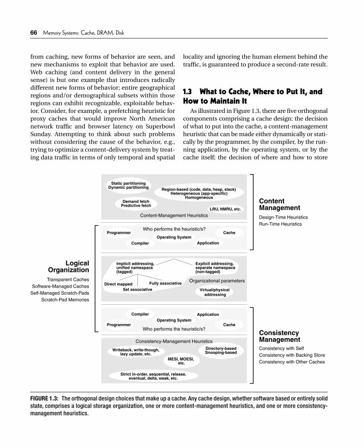
As illustrated in Figure 1.3, there are fi ve orthogonal components comprising a cache design: the decision of what to put into the cache, a content-management heuristic that can be made either dynamically or stati-cally by the programmer, by the compiler, by the run-ning application, by the operating system, or by the cache itself; the decision of where and how to store
Operating System
LogicalOrganization
ContentManagement
ConsistencyManagement
Who performs the heuristic/s?
Who performs the heuristic/s?
Programmer Cache
Explicit addressing,separate namespace(non-tagged)
Implicit addressing,unified namespace(tagged)
Direct mappedSet associative
Fully associative
Virtual/physical addressing
Writeback, write-though,
MESI, MOESI, etc.
Directory-basedSnooping-basedlazy update, etc.
Strict in-order, sequential, release,eventual, delta, weak, etc.
Static partitioningDynamic partitioning
Demand fetchPredictive fetch
Region-based (code, data, heap, stack)Heterogeneous (app-specific)
Homogeneous
Compiler Application
Operating SystemProgrammer Cache
Compiler Application
Content-Management Heuristics
Consistency-Management Heuristics
Organizational parametersTransparent CachesSoftware-Managed Caches
Self-Managed Scratch-PadsScratch-Pad Memories
Design-Time HeuristicsRun-Time Heuristics
Consistency with SelfConsistency with Backing StoreConsistency with Other Caches
LRU, NMRU, etc.
FIGURE 1.3: The orthogonal design choices that make up a cache. Any cache design, whether software based or entirely solid state, comprises a logical storage organization, one or more content-management heuristics, and one or more consistency-management heuristics.
ch01_P379751.indd Sec2:66ch01_P379751.indd Sec2:66 8/7/07 9:00:32 PM8/7/07 9:00:32 PM
Chapter 1 AN OVERVIEW OF CACHE PRINCIPLES 67
cached data within the cache’s physical extent and/or logical arrangement (its logical organization); and the mechanism by which the cache (together with any exe-cuting software) ensures the consistency of data stored within it, a heuristic that can be performed by any of several entities, including the application code, the operating system, or the cache itself. A cache can be built by combining essentially any logical organization with essentially any set of management heuristics.
This section sets up the next three chapters of the book. The three primary issues illustrated in Figure 1.3 (Logical Organization, Content Management, and Con-sistency Management) will be discussed here in an over-view fashion, and the next three chapters will go into each in more detail.
1.3.1 Logical Organization Basics: Blocks, Tags, Sets
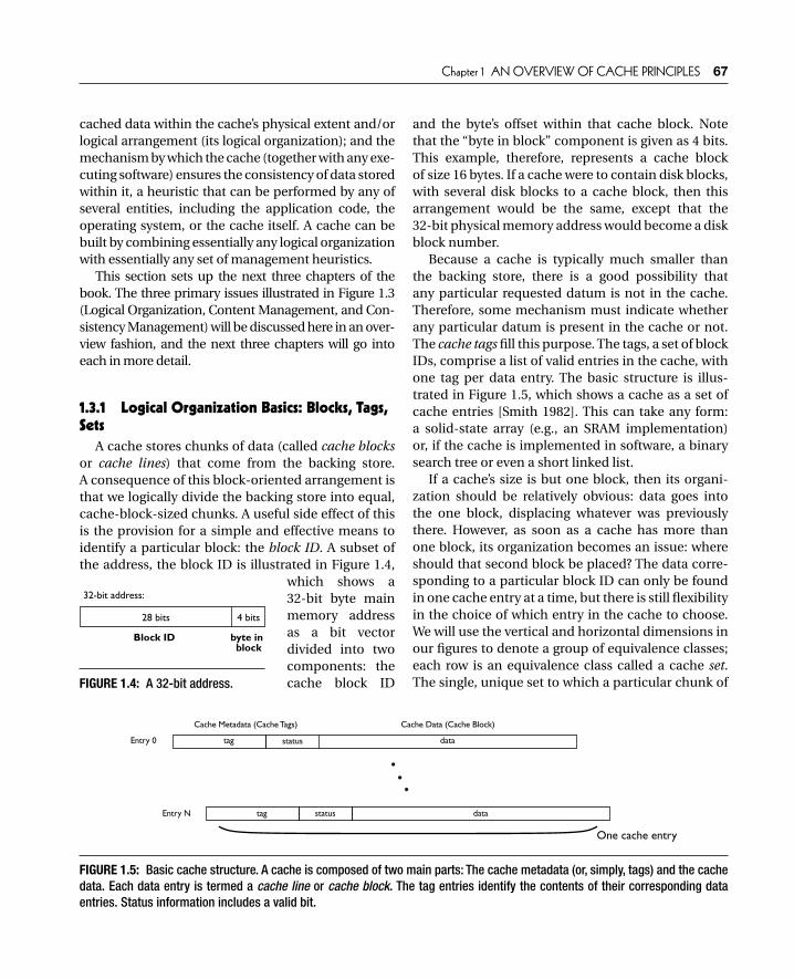
A cache stores chunks of data (called cache blocks or cache lines) that come from the backing store. A consequence of this block-oriented arrangement is that we logically divide the backing store into equal, cache-block-sized chunks. A useful side effect of this is the provision for a simple and effective means to identify a particular block: the block ID. A subset of the address, the block ID is illustrated in Figure 1.4,
which shows a 32-bit byte main memory address as a bit vector divided into two components: the cache block ID
and the byte’s offset within that cache block. Note that the “byte in block” component is given as 4 bits. This example, therefore, represents a cache block of size 16 bytes. If a cache were to contain disk blocks, with several disk blocks to a cache block, then this arrangement would be the same, except that the 32-bit physical memory address would become a disk block number.
Because a cache is typically much smaller than the backing store, there is a good possibility that any particular requested datum is not in the cache. Therefore, some mechanism must indicate whether any particular datum is present in the cache or not. The cache tags fi ll this purpose. The tags, a set of block IDs, comprise a list of valid entries in the cache, with one tag per data entry. The basic structure is illus-trated in Figure 1.5, which shows a cache as a set of cache entries [Smith 1982]. This can take any form: a solid-state array (e.g., an SRAM implementation) or, if the cache is implemented in software, a binary search tree or even a short linked list.
If a cache’s size is but one block, then its organi-zation should be relatively obvious: data goes into the one block, displacing whatever was previously there. However, as soon as a cache has more than one block, its organization becomes an issue: where should that second block be placed? The data corre-sponding to a particular block ID can only be found in one cache entry at a time, but there is still fl exibility in the choice of which entry in the cache to choose. We will use the vertical and horizontal dimensions in our fi gures to denote a group of equivalence classes; each row is an equivalence class called a cache set. The single, unique set to which a particular chunk of
28 bits 4 bits
Block ID byte in block
32-bit address:
FIGURE 1.4: A 32-bit address.
Cache Metadata (Cache Tags) Cache Data (Cache Block)
tag
tag data
dataEntry N
Entry 0
One cache entry
status
status
FIGURE 1.5: Basic cache structure. A cache is composed of two main parts: The cache metadata (or, simply, tags) and the cache data. Each data entry is termed a cache line or cache block. The tag entries identify the contents of their corresponding data entries. Status information includes a valid bit.
ch01_P379751.indd Sec2:67ch01_P379751.indd Sec2:67 8/7/07 9:00:32 PM8/7/07 9:00:32 PM

68 Memory Systems: Cache, DRAM, Disk
data belongs is typically determined by a subset of bits taken from its block ID, as shown in Figure 1.6. Once the set is determined, the data chunk may be placed within any block in that set.
There are three basic cache organizations that arise from this equivalence-class mechanism: direct-mapped, fully associative, and set associative. Direct-mapped caches have sets with only one block in each set; each block is its own equivalence class. Fully associative caches (also called content-addressable memories) have only one set that encompasses all blocks; thus, all blocks in the cache are in the same equivalence class. Set-associative caches strike a balance between these two choices. A set-associate cache has more than one set (if only one, the cache would be fully associative), and each set in the cache incorporates more than one block in its equivalence class (if only one, the cache would be direct-mapped). Figure 1.7 illustrates the three cache organizations by demonstrating the various ways a cache of eight blocks can be organized.
1.3.2 Content Management: To Cache or Not to Cache
As an application executes over time, it makes a sequence of references to memory (or, more generally, the backing store), each of which is a potential candi-date for caching. The purpose of a content-manage-ment solution is to determine which references are the best candidates for caching and to ensure that their corresponding data values are in the cache at the time the application requests them. Simultaneously, it must consider the currently cached items and decide which should be evicted to make room for more important data not yet cached. The optimal algorithm is one that can look into the future and determine what will be needed and ensure that all important data words, up to the limits of the cache’s capacity and organization, are in the cache when requested. This is similar in spirit to Belady’s MIN algorithm for disk block replacement [Belady 1966]. Both schemes rely upon an oracle to guarantee optimal performance.
Given the absence of an oracle, one is left with sub-optimal approaches, i.e., heuristics that can, at best, approximate the optimal approach, making do with imperfect and/or incomplete information. These heuristics take as input anything that might describe a data item: e.g., who is using it, how it is being used, how important it is, and at what point in the application’s execution is the item being consid-ered. Using this, the heuristic makes a “yes/no” deci-sion to cache the item. Note that the decision can be made at any of several different times, by any of sev-eral different entities. The time can be relatively early on in the process—for instance, when the program-mer writes and compiles the application code—or
28 bits 4 bits
Block ID byte in block
32-bit address:
28-n bits 4 bits
byte in block
n bits
Cache Tag Set no.
n-bit set # (also called the cache index)will support a cache with 2n sets
FIGURE 1.6: Different address views.
Direct-mapped Fully associative
Two-way set associative
Four-way set associative
equivalenceclasses
items in same set or equivalence class
(“sets”)
FIGURE 1.7: Four organizations for a cache of eight blocks. Eight blocks can be configured in a direct-mapped organization, a fully associative organization, or any of two different set-associative organizations.
ch01_P379751.indd Sec2:68ch01_P379751.indd Sec2:68 8/7/07 9:00:33 PM8/7/07 9:00:33 PM

Chapter 1 AN OVERVIEW OF CACHE PRINCIPLES 69
it can be made relatively late in the process—for instance, while the application code is executing. The decision can be made by the programmer, the com-piler, the operating system, the application code, or the cache itself. In addition, some decisions will be inherently predictive in nature (e.g., a design-time heuristic embedded in the compiler determines that a particular reference should hit the cache, so proac-tive steps such as prefetching should be performed to ensure that the data is in the cache at the time the ref-erence is made), while other decisions will be inher-ently reactive in nature (e.g., a run-time heuristic in the cache determines that a requested item is valu-able and therefore should remain in the cache once fetched from the backing store).
An important thing to bear in mind when consider-ing the role of the content-management solution (i.e., the set of design-time and/or run-time heuristics) is that the logical organization of the cache has the fi nal word on whether something a heuristic decides to cache will, in fact, remain cached. The logical organi-zation defi nes how and where cached data is stored, and if a heuristic chooses to cache two items that the logical organization cannot hold simultaneously, then one of the two must go. For example, consider two back-to-back references made to items deemed important by some heuristic, but positioned in the backing store’s namespace such that they are assigned to the same set in the cache (this would happen if the two items were stored in memory exactly 1 MB apart, given a cache of 1 MB in size or less), and, further, assume that the cache is not set associative (each set can hold only one data item). The cache can hold only one of these items, and so the second reference would displace the fi rst, irrespective of the heuristic’s wishes.
1.3.3 Consistency Management: Its Responsibilities
Consistency management comprises three main charges:
1. Keep the cache consistent with itself 2. Keep the cache consistent with the backing
store 3. Keep the cache consistent with other caches
In many cases, these goals can be accomplished simply. In most cases, the choice of logical organiza-tion can complicate things tremendously.
Keep the Cache Consistent with Itself There should never be two copies of a single item
in different places of the cache, unless it is guaranteed that they will always have the same value. In general, this tends not to be a problem, provided the cache is physically indexed and physically tagged.
Many operating systems allow two completely unrelated virtual addresses to map to the same physi-cal address, creating a synonym. The synonym prob-lem is non-trivial and is discussed in more detail in Chapter 4. It creates a problem by allowing the physi-cal datum to lie in two different virtually indexed cache sets at the same time, immediately creating an inconsistency as soon as one of those copies is writ-ten. If the cache’s sets are referenced using a physical address (i.e., an address corresponding to the back-ing store, which would uniquely identify the datum), then there is no problem.
Using tags that correspond to the backing store solves another problem. Even if some mechanism ensures that two synonyms map to the same set in the cache, the cache could nonetheless hold the two different copies if the cache is set associative and the two cache blocks are not tagged with an ID taken from the backing store. For example, if the cache uses vir-tual tags or if the cache fails to ensure that the blocks held in a set all have unique tags, then an inconsis-tency could occur.
Keep the Cache Consistent with the Backing StoreThe value kept in the backing store should be up-
to-date with any changes made to the version stored in the cache, but only to the point that it is possible to ensure that any read requests to the version in the backing store (e.g., from another processor) return the most recently written value stored in the cache.
Two typical mechanisms used in general-purpose caches to effect this responsibility are write-back and write-through policies. When writing to a cache, the backing store is implicitly updated, but when? Two
ch01_P379751.indd Sec2:69ch01_P379751.indd Sec2:69 8/7/07 9:00:33 PM8/7/07 9:00:33 PM

70 Memory Systems: Cache, DRAM, Disk
obvious choices are immediately and later; the fi rst is write-through, and the second is write back. Write-through offers the advantage of having a very small window in which the backing store has an outdated (“stale”) copy of a datum. Write-back takes advantage of locality in that, if a block is written, the block will likely be written again in the near future, in which case it would make no sense to transmit both values to the backing store. A write-back cache keeps track of blocks that have been written (called “dirty”) and writes their contents to memory only upon block replacement, potentially saving signifi cant band-width to the backing store.
The disadvantage of write-through is its cost: shoveling every write to the cache into the backing store at the same time becomes expensive, because the backing store typically cannot provide the same bandwidth as the cache. The solution is to provide an additional fast memory of some sort that is physi-cally part of the cache, but logically part of the back-ing store. Popular choices for this fast memory are FIFO (fi rst-in fi rst-out) write buffers, coalescing write buffers, or searchable write buffers, a.k.a. write caches. The point of this hardware is to decouple the bursty nature of the microprocessor’s write opera-tions from the backing store and to dribble the writ-ten data to the backing store at whatever speed it can handle. The simple write buffer must be drained if it fi lls or if a cache miss occurs. More complex write buffers are capable of much more sophisticated behavior.
The primary disadvantage of write-back caches is their interaction with other processors and other processes. In the fi rst case, in a multiprocessor orga-nization, having a long window of time wherein the backing store can have the wrong value for a particular datum increases the likelihood that another processor sharing the backing store will read that (wrong) datum. We will discuss this later in Chapter 4. In the second case, the virtual memory system’s synonym problem complicates things tre-mendously. Consider, for example, the case when a process writes into its address space, exits, and part of its data space is reused when another process is created or dynamically allocates memory in its heap or stack segments. Nothing prevents a write-back
virtually indexed cache from overwriting the new process’s address space when those cache blocks are fi nally replaced. Even if the operating system wipes the data pages clean, the old written data from the fi rst process can still be found in the cache if the operating system uses different virtual addresses or a different address-space identifi er than the original process.
Keep the Cache Consistent with Other CachesOther caches in the system should all be treated
much like the backing store in terms of keeping the various copies of a datum up-to-date, as in Item #2 above.
Note that we are using the term consistent here in the normal, Merriam-Webster sense; we are not talking about memory consistency, a mechanism to specify the ordering of reads and writes that a (multi-processor) system as a whole sees.
1.3.4 Inclusion and ExclusionBefore we move on, an aspect of cache organization
and operation needs discussion: inclusion. The con-cept of inclusion combines all three aspects of caching just described. Inclusion can be defi ned by a cache’s logical organization, and it is enforced by the cache’s content- and consistency-management policies.
Figure 1.8 gives a picture of the canonical memory hierarchy. The hierarchy is vertically partitioned into separate storage levels, and each level can be hori-zontally partitioned further [Lee & Tyson 2000]. This horizontal partitioning is also called a multi-lateral cache [Rivers et al. 1997]. Partitioning is a powerful mechanism. For instance, Lee and Tyson [2000] note that much work in cache-level energy reduction has been to exploit these divisions. One can use vertical partitioning and move more frequently accessed data into storage units that are closer to the microproces-sor—units that can be made signifi cantly smaller than units further out from the microprocessor (e.g., the line buffer [Wilson et al. 1996]), and thus typically consume less energy per reference [Kin et al. 1997, 2000]. Similarly, one can use horizontal partitioning and slice a logically monolithic cache into smaller
ch01_P379751.indd Sec2:70ch01_P379751.indd Sec2:70 8/7/07 9:00:34 PM8/7/07 9:00:34 PM

Chapter 1 AN OVERVIEW OF CACHE PRINCIPLES 71
segments (e.g., subbanks [Ghose & Kamble 1999]), each of which consumes a fraction of the whole cache’s energy and is only driven when a reference targets it directly.
The principles of inclusion and exclusion defi ne a particular class of relationship that exists between any two partitions in a cache system. Whether the two partitions or “units” are found at the same level in the hierarchy or at different levels in the hierarchy, there is a relationship that defi nes what the expected inter-section of those two units would produce. That rela-tionship is either exclusive or inclusive (or a hybrid of the two). Figure 1.9 illustrates a specifi c memory hierarchy with many of its relationships indicated.
An inclusive relationship between two fundamen-tal units is one in which every cached item found in one of the units has a copy found in the other. For example, this is the relationship that is found in many
(but not all) general-purpose, processor cache hierar-chies. Every cache level maintains an inclusive rela-tionship with the cache level immediately beneath it, and the lowest level cache maintains an inclusive relationship with main memory. When data is moved from main memory into the cache hierarchy, a copy of it remains in main memory, and this copy is kept consistent with the copy in the caches; i.e., when the cached copy is modifi ed, those modifi cations are propagated at some point in time to main memory. Similarly, copies of a datum held within lower lev-els of the cache hierarchy are kept consistent with the copies in the higher cache levels. All this is done transparently, without any explicit direction by the cache system’s client.
Keeping all of these additional copies spread around the memory system would seem wasteful. Why is it done? It is done for simplicity of design and
CPU
Level 1
Level 2
Level i
Permanent Store
. . .
Level N
. . .
Fundamental storage units that make up memory level i
...
The various units at level i could be different storage organizations (e.g.,two different caches) or parts of the same storage organization (e.g., thesets of a set-associative cache or the sectors of a disk).
FIGURE 1.8: A canonical memory hierarchy. As one moves down through the hierarchy, from the central processor toward the permanent store, the levels are larger but slower. At each level, the storage may be a monolithic organization, or it may be partitioned into multiple segments we have called generically “units.” Every fundamental unit has an exclusive or inclusive relationship with every other unit in the hierarchy.
ch01_P379751.indd Sec2:71ch01_P379751.indd Sec2:71 8/7/07 9:00:34 PM8/7/07 9:00:34 PM

72 Memory Systems: Cache, DRAM, Disk
correctness of design. If an inclusive relationship exists between partitions A and B (everything in A is also held in B, and B is kept consistent with the copy in A), then A can be considered nothing more than an opti-mized lookup: the contents of A could be lost forever, and the only signifi cant effect on the system would be a momentary lapse of performance, a slightly higher energy drain, until A is refi lled from B with the data it lost. This is not a hypothetical situation. Low-power caching strategies exist that temporarily power-down portions of the cache when the cache seems underuti-lized (e.g., a bank at a time). Similarly, the arrangement
simplifi es eviction: a block can be discarded from a cache at any time if it is known that the next level in the hierarchy has a consistent copy.
An exclusive relationship between two units is one in which the expected intersection between those units is the null set: an exclusive relationship between A and B specifi es that any given item is either in A or B or in neither, but it absolutely should not be in both. The content- and consistency-management protocols, whether implemented by the applica-tion software, the operating system, the cache, or some other entity, are responsible for maintaining
Fundamental storage units that make up cache
Fundamental storage units that make up operating store
Fundamental storage units that make up permanent store
An inclusive relationshipcould exist between, e.g., two different disk drivesin a mirrored organization
An exclusive relationshipwould exist between, e.g., a direct-mapped cacheand its victim cache
An inclusive relationshipwould exist between, e.g., an instruction cache and the DRAM system
An exclusive relationshipmight exist between, e.g., DRAM and boot ROM/firmware
DataCache
VictimCache
ROM DRAM Subsystem
Two Mirrored Disk DrivesFlash
(once the systemhas booted)
CPU
InstructionCache
(shown as 8 individual banks)
(n sets) (n sets)
(each of which is shown as a collection of sectors)
(1 set)
FIGURE 1.9: A specific memory hierarchy. A specific example of a memory system shows various vertical and horizontal partitions that can exist, as well as the inclusive/exclusive relationship between many of the fundamental storage units.
ch01_P379751.indd Sec2:72ch01_P379751.indd Sec2:72 8/7/07 9:00:35 PM8/7/07 9:00:35 PM

Chapter 1 AN OVERVIEW OF CACHE PRINCIPLES 73
exclusion between the two partitions. In particular, in many designs, when an item is moved from A to B, the item must be swapped with another item on the other side (which is moved from B to A). This is required because, unlike inclusive relationships in which a replaced item can be simply and safely dis-carded, there are no “copies” of data in an exclusive relationship. All instances of data are, in a sense, orig-inals—loss of a data item is not recoverable; it is an error situation.
Note that there are many examples of cache units in which this swapping of data never happens because data items are never moved between units. For example, the sets of a direct-mapped or set-asso-ciative cache exhibit an exclusive relationship with each other; they are partitions of a cache level, and when data is brought into that cache level, the data goes to the one partition to which it is assigned, and it never gets placed into any other set, ever.6
1.4 Insights and Optimizations
1.4.1 PerspectiveUsing general terms, we intentionally describe
traditional concepts such as locality, inclusion/exclu-sion, coherence/consistency, cache organization, protocols, policies, heuristics, etc. to make it clear that they are universally applicable to all manners of cache implementation. One item that should follow from this general treatment is for the reader to rec-ognize potential relationships between mechanisms that are not usually considered related or even com-patible. This general treatment should make obvi-ous to the reader potentially interesting avenues for research. As an example,
Figure 1.3 makes it clear that having different entities perform the same type of heuristic is a complementary action. For instance, both hardware and software could perform
•
content management simultaneously, much in line with hybrid branch predictors or as is already done with software-prefetching schemes (where both cache and software can decide to store items in the cache).Considering the sets of a transparent cache as having an exclusive relationship with each other begs the question, why? Why not allow some things to reside in multiple sets of a direct-mapped or set-associative cache? Perhaps naming can be a way to accomplish this simply, i.e., through the compiler or virtual memory system (using a virtually indexed cache). Note that this would com-plicate consistency management.Similarly, if one looks at a (set-associative) cache as just a collection of equivalence classes, there is no reason to require each set to have the same cardinality, i.e., to have the same degree of set associativity. Some sets could be large, and others could be small, just as a cache partition could be large or small. Some could have different organiza-tions entirely, with naming schemes used to assign items to different sets or equivalence classes. This is already done in fi le caching (e.g., see Chapter 2, Section 2.6.2, “A Soft-ware Implementation: BSD’s Buffer Cache”), and in a solid-state implementation it would be similar in spirit to the work done by Farrens, Rivers, Tyson, and others [Tyson et al. 1995, Rivers & Davidson 1996, John-son & Hwu 1997] in their work on alternative content-management strategies (discussed in more detail in Chapter 3, Section 3.1.1, “On-Line Partitioning Heuristics”).Given that content management is orthogonal to cache organization (clear from Figure 1.3), one can start to com-bine traditionally separated heuristics and organizations. For instance, one could use scratch-pad placement solutions to solve the problems of cache-set assignment.
•
•
•
6This is mostly, but not completely, true. See the discussion of problems in virtual caches (Chapter 4, Section 4.2.1, “Virtual Cache Management”), and the section on trace caches (Chapter 2, Section 2.6.3, “Another Dynamic Cache Block: Trace Caches”).
ch01_P379751.indd Sec2:73ch01_P379751.indd Sec2:73 8/7/07 9:00:35 PM8/7/07 9:00:35 PM

74 Memory Systems: Cache, DRAM, Disk
The list goes on. The whole point of starting from the basics and using general terms is to facilitate novel applications of the tremendous amount of work done in cache design (across many different areas) into new areas.
Reconsidering Bandwidth and Block Size: DSP Caches
One example of the types of opportunities that become available when traditional lines are crossed is a study originally done several years ago [ Srinivasan et al. 2001], the idea for which only came about because the traditional line between DSP caches and general-purpose caches had been crossed by the DSP community in their desire to compile C code for DSP architectures. The following is a brief excerpt7 of the study.
As mentioned earlier, DSPs typically use a non-uniform addressing model in which the primary components of the memory system, the DRAM and dual tagless SRAMs, are referenced through sepa-rate segments of the address space (see Figure 1.2). The recent trend of programming DSPs in high-level languages instead of assembly code has exposed this memory model as a potential weakness, as the model makes for a poor compiler target. In many of today’s high-performance DSPs, this non-uniform model is being replaced by a uniform model, a transparent organization like that of most general-purpose sys-tems, in which all memory structures share the same address space as the DRAM system.
This opens up an interesting design space to study—how best to build transparent caches for DSPs, perhaps exploiting the regular behavior exhib-ited by many applications on DSP processors (similar in vein to vector apps on vector processors), as well as their use of memory resources (ports), a behavior that resembles an exclusive partition and is very pre-dictable. For example, DSPs might be able to make good use of large cache blocks, particularly block sizes where a general-purpose application might
exhibit high degrees of cache pollution. An obvious downside of doing so is the long fi ll-time for large blocks, but this can be offset with increased memory bandwidth.
We look at two different organizations illustrated in Figure 1.10. The fi rst is an extremely simple orga-nization: two blocks, each one dedicated to a differ-ent load/store unit. The second adds a single-block victim cache [Jouppi 1990] to each of the blocks in the fi rst organization. In this organization, each vic-tim cache block holds only victims taken from its associated cache block. Note that in all organiza-tions, cache reads may be satisfi ed out of any block in the cache. The tying of a block to a particular load/store unit is simply used in the replacement policy; it does not affect the cache lookup mechanism. Any load/store unit can read a value from any block in the cache, which makes the cache effectively fully associative.
This is a rather non-traditional cache organiza-tion, but it follows from our observations of the behavior of ’C6000 DSP applications. In particular, we found that the C compiler tends to assign load and store instructions to particular ports in a manner that does not change dynamically: to wit, if the DSP reads a particular datum from a particular port, the DSP is less than 50% likely to read that datum from the other port in the near future, and it is far less than 50% likely to write that datum to the other port in the near future. We exploit the observed behavior by con-straining which blocks can be replaced and written from which ports, thereby creating a simpler cache. Note that this behavior is specifi c to compiled appli-cations, as opposed to DSP applications written by hand in assembly code, but it is also likely that the observed behavior would be seen in any DSP with a unifi ed memory space and a high-level language compiler.
Figure 1.11 shows the performance of the two organizations, compared to the performance of the 64-KB scratch-pad SRAM at 400 MB/s. Note that the vertical scales of the various graphs differ.
7This work is based on an earlier work: “Transparent data-memory organizations for digital signal processors,” by S. Srinivasan, V. Cuppu, and B. Jacob, in Proc. International Conference on Compilers, Architecture, and Synthesis for Embedded Systems (CASES 2001), November 2001. © ACM, 2001. http://doi.acm.org/10.1145/502217.502224
ch01_P379751.indd Sec2:74ch01_P379751.indd Sec2:74 8/7/07 9:00:35 PM8/7/07 9:00:35 PM

Chapter 1 AN OVERVIEW OF CACHE PRINCIPLES 75
cache entry 2 (tag + data)
cache entry 1 (tag + data)
victim entry 2 (tag + data)
victim entry 1 (tag + data)
cache entry 2 (tag + data)
cache entry 1 (tag + data)
Port 1
Port 2
Port 1
Port 2
(a) Simple organization (b) Victim-cache organization
LDST .D1
LDST .D2
LDST .D1
LDST .D2
FIGURE 1.10: Slightly non-traditional cache organizations. Each load/store unit can read from any block in the cache, but it can only write to the primary block that is assigned to it. Similarly, load misses only fill the cache block assigned to a load/store unit. The victim cache organization adds two blocks to the cache that are only filled by blocks replaced from the corresponding primary blocks.
UTDSP Applications (average) UTDSP Kernels (average)
setyb 4
setyb 8
setyb 61
setyb 23
setyb 46
setyb 821
setyb 652
setyb 215
MARS
)ceS/BM004(Cache Block Width
0
2
4
6
8
10
12
14
noitcurtsnI rep selcyC
0
20
40
)selcyC( ycn eta L g v
A
setyb 4
setyb 8
setyb 61
setyb 23
setyb 46
setyb 821
setyb 652
setyb 215
MARS
)ceS/BM004(Cache Block Width
0
2
4
6
8
10
12
14
16
18
noitcurtsnI rep selcyC
0
20
40
)selcyC( ycnetaL g v
A
simple simple
setyb 4
setyb 8
setyb 61
setyb 23
setyb 46
setyb 821
setyb 652
setyb 215
MARS
)ceS/BM004(Cache Block Width
0
1
2
3
4
5
noitcurtsnI rep s elcyC
0
10
20
30
40
)selcyC( ycnet aL gv
A
setyb 4
setyb 8
setyb 61
setyb 23
setyb 46
setyb 821
setyb 652
setyb 215
MARS
)ceS/BM004(Cache Block Width
0
1
2
3
4
5
noitcurtsnI rep s elc yC
0
10
20
30
40
)selcyC( ycn et aL gv
A
CPI 400 MB/secCPI 800 MB/sCPI 1200 MB/sCPI 1600 MB/s
Avg Latency 400 MB/sAvg Latency 800 MB/sAvg Latency 1200 MB/sAvg Latency 1600 MB/s
UTDSP Applications (average) UTDSP Kernels (average)
victim-cache victim-cache
FIGURE 1.11: Performance graphs. The top two graphs give results for the “simple” organization. The bottom two give results for the “victim cache” organization.
ch01_P379751.indd Sec2:75ch01_P379751.indd Sec2:75 8/7/07 9:00:36 PM8/7/07 9:00:36 PM

76 Memory Systems: Cache, DRAM, Disk
Execution time (in CPI) is given on the left side of each graph, corresponding to the histograms; aver-age latency per memory instruction is given on the right side of each graph, corresponding to the line graphs. Memory bandwidth and cache block size are the variables (note that total cache capacity is not kept constant and instead grows as block size grows).
In general, if one is willing to pay for more band-width, one can get away with signifi cantly less on-chip storage and reach the same levels of performance. This represents an interesting trade-off between chip costs in on-chip storage and system costs in memory bandwidth. That one can approach the performance of the traditional DSP memory organization with such a simple structure is a natural consequence of the fact that DSP applications typically stream data, obviating large cache structures and making stream buffers more attractive.
Reconsidering Permanent Store: Plan 9’s File SystemAnother example of interesting cache designs is
Plan 9’s fi le system,8 in which the designers re-defi ned the concept of “permanent store” [Quinlan 1991]. The operating system treats the entire magnetic disk system as a mere cache for the backup system (the WORM [write once, read many] jukebox, a jukebox of write-once/read-many optical disks9), which is con-sidered the repository of the true fi le system and thus the ultimate in permanent backing store.
The work is based upon earlier explorations in the same general direction. For instance, Garfi nkel [1986] describes a fi le-system API (application pro-gramming interface) that moves copies of fi les to backup whenever those fi les are written. The File Motel [Hume 1988] uses the WORM drive as a trans-parent backup for the fi le system, which resides as normal on the magnetic disk system. A separate mag-netic-disk-resident database maps fi les to locations
on the WORM drive, and the design is such that the mapping database can be reconstructed from the WORM-resident permanent data if the magnetic disk ever crashes. The disadvantage of the design is that copies to backup (the WORM system) can take sig-nifi cant time, resulting in snapshots that are far from atomic (e.g., one can still modify the fi le system while it is being backed up to the WORM drive, which cre-ates the potential for inconsistency).
Tektronix’s Optical File Cabinet [Gait 1988, Laskodi et al. 1988] addresses this issue by placing the fi le sys-tem into the WORM drive itself, so there is always an atomic snapshot of the system. The fi le system uses a logical namespace that is different from the WORM’s physical namespace, because the fi le system trans-parently maps fi les to the WORM space, creating a new WORM-resident block and remapping the logi-cal block every time a block is updated by applica-tion or Operating System software. Because every block-write allocates a new block in the WORM drive, the fi les system’s logical namespace must necessarily be signifi cantly smaller than the WORM’s physically available namespace. It is possible to write a logi-cal block many times, creating many backups of the block on the WORM drive.
In the design described by Quinlan [1991], the best of both worlds is reached by combining the full namespace of the backing store with the magnetic-disk storage medium. The Operating System’s fi le system resides on the backup device, because the fi le system identifi es its blocks using the namespace offered by the backup device. The operating system uses the faster magnetic-disk space as a transpar-ent cache. Instead of creating a new WORM block on every write, the Plan 9 fi le system creates one on every backup event (e.g., once every night), holding the newly written data on magnetic disk until that point. This is similar in nature to a write-back cache, whereas the Optical File Cabinet is more akin to a write-through cache.
8Plan 9 is the (whimsical) name given to version 9 of the Unix operating system.9This research occurred at a time when WORM disks were available, cost roughly the same as magnetic tape, were signifi -cantly faster than tape, had a longer shelf-life than magnetic tape, and offered storage densities an order of magnitude larger than rewritable optical media [Hume 1988].
ch01_P379751.indd Sec2:76ch01_P379751.indd Sec2:76 8/7/07 9:00:37 PM8/7/07 9:00:37 PM

Chapter 1 AN OVERVIEW OF CACHE PRINCIPLES 77
1.4.2 Important Issues, Future DirectionsResearch in cache design is by no means at a stand
still, and the future holds numerous avenues for inter-esting work. For SRAM-based caches in particular, power dissipation and reliability are primary issues. A rule of thumb is that SRAMs typically account for at least one-third of the power dissipated by micropro-cessors, and the reliability for SRAM is the worst of the technologies surveyed in this book.
On the power-dissipation front, the decline in importance of dynamic power with respect to leakage power changes some traditional rules. For instance, fully associative caches have long been a staple for applications that require high hit rate with a minimum of storage, but they are often avoided due to their high dynamic power dissipation. As leakage power comes to dominate total power, these caches are likely to become more popular, as they can require signifi cantly less storage (and thus fewer transistors) than an equiv-alently performing direct-mapped or set-associative cache. Fewer transistors means less leakage power.
Taking a different approach, building on-chip caches out of alternative technologies, such as embed-ded DRAM (eDRAM), is also a promising direction. Though studies in the past have dismissed eDRAM as having unacceptable performance in general-pur-pose environments, there are several factors at work to counter these initial results, given enough time.
1. The working sets of many high-end appli-cations are growing at a phenomenal pace, making DRAM-based solutions attractive due to their density.
2. The performance of eDRAM technolo-gies is improving to the point that eDRAM matches the performance of off-chip SRAM caches.
3. Embedded DRAM is available in many logic-based processes and even there has a higher reliability than SRAM.
4. Embedded DRAM is expected to dissipate signifi cantly less power, both dynamic and static, compared to SRAM caches.
Another issue for future study is the incredible opportunity for exploring signifi cantly more sophis-ticated algorithms for content and consistency management as multiple cores and their associated last-level cache controller all move onto the same die. When the last-level cache controller was off-chip (e.g., as part of the system controller), it ran at a sig-nifi cantly slower speed than the microprocessors it served. Moving it onto the same die can increase ten-fold the amount of work it can do during the same request. In addition, moving the controller on-chip opens up possibilities for information sharing, giving the controller more access to system state than it ever had before.
Finally, the application of cache principles to new areas that have not traditionally used caches is always a promising area, one that should become very interesting as the sophistication of the various heuristics that can be built grows. For example, the original development of complex block-replacement algorithms, such as least-recently-used (LRU), was done in the context of the operating system’s buf-fer cache, which could afford high-complexity heu-ristics as the heuristics would be performed in the background of a disk block fetch, a relatively lengthy operation. Such complexity was unthinkable for heu-ristics in other areas such as solid-state processor caches. Nonetheless, as the technologies from which caches were built in other disciplines grew in capabil-ity, these disciplines adopted the same type of analy-sis and heuristics as the operating system’s buffer cache. Currently, the computer-architecture world has explored numerous sophisticated heuristics for prefetching data and dynamic classifi cation of loads. It is only a matter of time before these mechanisms appear elsewhere.
ch01_P379751.indd Sec2:77ch01_P379751.indd Sec2:77 8/7/07 9:00:37 PM8/7/07 9:00:37 PM