Embed Size (px)
Citation preview
5/14/2018 Cable Tray Installation Nema Ve2 - slidepdf.com
http://slidepdf.com/reader/full/cable-tray-installation-nema-ve2 1/51
NEMA Standards Publication VE 2-2000
Cable Tray Installation Guidelines
Published by:
National Electrical Manufacturers Association1300 North 17th StreetRosslyn, VA 22209
Approved by:
Cable Tray Institute1300 North 17th StreetRosslyn, VA 22209
© Copyright 2001 by the National Electrical Manufacturers Association. All rights including translation intoother languages, reserved under the Universal Copyright Convention, the Berne Convention for theProtection of Literary and Artistic Works, and the International and Pan American Copyright Conventions.

5/14/2018 Cable Tray Installation Nema Ve2 - slidepdf.com
http://slidepdf.com/reader/full/cable-tray-installation-nema-ve2 2/51
NEMA VE 2-2000Page i
© 2001 National Electrical Manufacturers Association
Contents
Foreword ...........................................................................................................................iii
Scope ............................................................................................................................... iv
Section 1 GENERAL.........................................................................................................................1
Section 2 RECEIVING AND UNLOADING .......................................................................................3
Section 3 STORAGE.........................................................................................................................5
Section 4 INSTALLATION.................................................................................................................74.1 Common Tools for Installation ..........................................................................................7
4.2 Support Installation............................................................................................................74.3 Straight Section Installation.............................................................................................164.4 Fittings Installation...........................................................................................................244.5 Field Modifications........................................................................................................... 264.6 Accessories.....................................................................................................................294.7 Grounding and Bonding ..................................................................................................34
Section 5 INSTALLATION OF CABLE............................................................................................395.1 General............................................................................................................................395.2 Handling and Storage .....................................................................................................395.3 Cable Tray Preparation...................................................................................................395.4 Cable Pulling Considerations..........................................................................................395.5 Pulling the Cable .............................................................................................................40
5.6 Fastening of Cables ........................................................................................................415.7 Protecting Installed Cable ...............................................................................................42
Section 6 MAINTENANCE ..............................................................................................................436.1 Inspection........................................................................................................................436.2 Inactive or Dead Cables..................................................................................................436.3 Adding Cables .................................................................................................................43
Appendix A TYPICAL CABLE TRAY TYPES.....................................................................................45

5/14/2018 Cable Tray Installation Nema Ve2 - slidepdf.com
http://slidepdf.com/reader/full/cable-tray-installation-nema-ve2 3/51
NEMA VE 2-2000Page ii
© 2001 National Electrical Manufacturers Association

5/14/2018 Cable Tray Installation Nema Ve2 - slidepdf.com
http://slidepdf.com/reader/full/cable-tray-installation-nema-ve2 4/51
NEMA VE 2-2000Page iii
© 2001 National Electrical Manufacturers Association
Foreword
For Cable Tray Installers—This publication is intended as a practical guide for the proper installation of cable tray systems. Cable tray systems design shall comply with NEC Article 318, NEMA VE 1, andNEMA FG 1 and follow safe work practices as described in NFPA 70E.
These guidelines and information do not intend to cover all details or variations in cable traysystems nor provide for every possible installation contingency.
Construction Experience—It is recommended that the work described be performed by qualifiedpersons familiar with standard electrical construction practices, electrical equipment, and safety of electrical wiring systems.
These guidelines will be useful to engineers, contractors, and maintenance personnel. This publicationwill be reviewed periodically with the purpose of updating it to reflect advancing technology andconstruction techniques. Please address any comments or questions to:
Vice President, Engineering or Technical Director
National Electrical Manufacturers Association Cable Tray Institute1300 North 17th Street 4101 Lake Boone TrailSuite 1874 Suite 201Rosslyn, VA 22209 Raleigh, NC 27607-6518
This is the second edition of this publication.
This standards publication was developed by the NEMA Metal Cable Tray and Nonmetallic Cable TraySections. Section approval of the standard does not necessarily imply that all section members voted for itsapproval or participated in its development. At the time it was approved, the Metal Cable Tray and NonmetallicCable Tray Sections were composed of the following members:
Champion Fiberglass—Spring, TX
Chalfant Manufacturing Company—Cleveland, OHCooper B-Line—Highland, ILEnduro Fiberglass Systems, Inc.—Houston, TX GS Metals Corporation—Pinckneyville, ILMP Husky Corporation—Greenville, SCP-W Industries, Inc.—Atlanta, GASeasafe, Inc.—Lafayette, LA Square D Company—Oxford, OHThomas & Betts Corporation—Memphis, TNT. J. Cope, Inc.—Wayne, MITex Tray Inc.—Houston, TXThe Wiremold Company—West Hartford, CT
DISCLAIMER
The standards or guidelines presented in a NEMA Standards Publication are considered technicallysound at the time they are approved for publication. They are not a substitute for a product seller's or user's own judgment with respect to the particular product referenced in the standard or guideline, andNEMA does not undertake to guarantee the performance of any individual manufacturer's products byvirtue of this standard or guide. Thus, NEMA expressly disclaims any responsibility for damages arisingfrom the use, application, or reliance by others on the information contained in these standards or guidelines.

5/14/2018 Cable Tray Installation Nema Ve2 - slidepdf.com
http://slidepdf.com/reader/full/cable-tray-installation-nema-ve2 5/51
NEMA VE 2-2000Page iv
© 2001 National Electrical Manufacturers Association
SCOPE
This publication addresses shipping, handling, storing, and installing cable tray systems. Information onmaintenance and system modification is also provided.
Abbreviations used in this standard are as follows:
“in” denotes inch;“ft” denotes foot;“lb” denotes pound;“mm” denotes millimeter;“kg” denotes kilogram;“m” denotes meter;“N” denotes newtons;
“°F” denotes degree Fahrenheit;
“°C” denotes degree Celsius.

5/14/2018 Cable Tray Installation Nema Ve2 - slidepdf.com
http://slidepdf.com/reader/full/cable-tray-installation-nema-ve2 6/51
NEMA VE 2-2000
Page 1
© 2001 National Electrical Manufacturers Association
Section 1
GENERAL
WARNING!—Do not use a cable tray as a walkway, ladder, or support for people; cable tray is amechanical support system for cables and raceways. Using cable trays as walkways can cause personalinjury and also damage cable tray and installed cables.
Hazardous voltages in electrical equipment can cause severe personal injury or death. Safety relatedwork practices, as described in NFPA 70E, Part 11, should be followed at all times.
The performance of a cable tray wiring system is dependent on its proper installation, including supportsand cables. Neglecting installation and maintenance guidelines may lead to personal injury as well asdamage to property.
Installation and maintenance of cable tray wiring systems shall be conducted only by qualified personnel.For the purposes of this guideline, a qualified person is one who is familiar with electrical construction. Inaddition, the person is:
Trained and authorized to test, energize, clear, ground, tag, and lock out circuits in accordancewith established safety practices.
Trained in the proper care and use of protective equipment such as insulated rubber gloves,hard hat, safety glasses or face shields, dust mask, and flash resistant clothing in accordancewith established safety practices.

5/14/2018 Cable Tray Installation Nema Ve2 - slidepdf.com
http://slidepdf.com/reader/full/cable-tray-installation-nema-ve2 7/51
NEMA VE 2-2000Page 2
© 2001 National Electrical Manufacturers Association

5/14/2018 Cable Tray Installation Nema Ve2 - slidepdf.com
http://slidepdf.com/reader/full/cable-tray-installation-nema-ve2 8/51
NEMA VE 2-2000
Page 3
© 2001 National Electrical Manufacturers Association
Section 2
RECEIVING AND UNLOADING
Cable tray is generally bundled and shipped via motor freight, except for export shipments that could becrated or loaded in containers. Accessories and small components are boxed and often skidded.
Cable tray can be shipped via enclosed van, trailer, or flat bed trailer. Van trailers are normally used for less than truckload (LTL) shipments. This method of shipment is most common and cost effective andoffers maximum protection from the weather during shipment. LTL shipments should be hand unloadedunless provisions have been made with the cable tray manufacturer for forklift unloading.
Flat bed trailers are often used for full truckload shipments and when customers want side forkliftunloading or sling unloading by crane. (Special care must be exercised using slings so cable tray is notcrushed from the improper location and lifting by sling.)
CORRECT NOT CORRECT MNNNNOT CORR
*Except when utilizing extended forks for skidded bundles
Small to medium size orders less than 2000 ft. (600 m) are generally shipped via common carrier - LTL inenclosed vans.
If hand unloaded, workers should wear gloves.
To prevent damage to cable tray, never pull cable tray from truck trailer by chaining to bottom rung anddragging out of trailer.
CORRECT NOT CORRECT
Inventory all items immediately after unloading, using the manufacturer's packing list. Note on the bill of lading any shortage or shipping damage for filing freight claim.

5/14/2018 Cable Tray Installation Nema Ve2 - slidepdf.com
http://slidepdf.com/reader/full/cable-tray-installation-nema-ve2 9/51
NEMA VE 2-2000Page 4
© 2001 National Electrical Manufacturers Association
5/14/2018 Cable Tray Installation Nema Ve2 - slidepdf.com
http://slidepdf.com/reader/full/cable-tray-installation-nema-ve2 10/51
NEMA VE 2-2000
Page 5
© 2001 National Electrical Manufacturers Association
Section 3
STORAGE
Hot dipped galvanized after fabrication (H.D.G.A.F.) (see ASTM A 123) steel, aluminum, and stainlesssteel cable tray and fiberglass or other non-metallic cable tray can be stored outside without cover, butshould be loosely stacked, elevated off the ground, and ventilated to prevent storage stain. If appearanceis important, cable tray should be stored indoors to prevent water or other foreign materials from stainingor adhering to cable tray.
Mill galvanized (see ASTM A 653) or electro-galvanized (see ASTM B 633) cable tray must be protectedor stored in a well ventilated, dry location.
Bare steel cable tray should receive a protective coating as soon as possible to prevent surface rust.
PVC or painted cable tray should be protected and stored indoors if possible. Cable tray must beprotected from scratching and marring of finish.
Small accessories should be stored to prevent loss.
Cable tray should be stored away from high traffic areas. Cable tray should be stacked by width and type.

5/14/2018 Cable Tray Installation Nema Ve2 - slidepdf.com
http://slidepdf.com/reader/full/cable-tray-installation-nema-ve2 11/51
NEMA VE 2-2000Page 6
© 2001 National Electrical Manufacturers Association

5/14/2018 Cable Tray Installation Nema Ve2 - slidepdf.com
http://slidepdf.com/reader/full/cable-tray-installation-nema-ve2 12/51
NEMA VE 2-2000
Page 7
© 2001 National Electrical Manufacturers Association
Section 4
INSTALLATION
For Cable Tray Installers—This publication is intended as a practical guide for the proper installation of cable tray systems. Cable tray system design shall comply with NEC Article 318, NEMA VE 1, andNEMA FG 1, and shall follow safe work practices as described in NFPA 70E.
These instructions and information do not intend to cover all details or variations in cable tray systems nor provide for every possible installation contingency.
Construction Experience—It is recommended that the work described be performed by qualifiedpersons familiar with standard electrical construction practices, electrical equipment, and safety of electrical wiring systems.
4.1 COMMON TOOLS FOR INSTALLATION
The following tools are commonly used for installation of cable tray:
• Metal cutting saw • Leveling device
• Touch-up material • Tape measure
• Screwdriver • Square
• Drill with bits • C-clamp
• File • Torque wrench
• Open end wrench • Ratchet wrench
• Nylon cord or laser • Offset Bolt cutters (Wire mesh)
• Sealant for cut edges (Fiberglass) • Dust Mask (Fiberglass)
• Cutting Saw (Fiberglass) Carbide or Diamond Tipped • Appropriate safety equipment
4.2 SUPPORT INSTALLATION
Caution! Do not cut or drill structural building members (e.g. I-beams) without approval by the generalcontractor.
In order to install the cable tray supports, first find the required elevation from the floor to the bottom of the cable tray and establish a level line with a laser or a nylon string. A string works well because it canbe used to align the threaded rods on one side of a trapeze and find the tops of the supports.
In order to speed the process of installing the trapeze hangers, some nuts may be pre-threaded onto thethreaded rod to the approximate location where the nut will be needed. One method for pre-threading thenuts is to put the nuts onto the end of a piece of threaded rod, attach a drill to the threaded rod, and runthe nuts up the rod holding onto them with an open-end wrench.
NOTE—Nonmetallic supports and hardware may require special load bearing considerations due to materialcomposition and application temperature. Consult the cable tray manufacturer for recommended practices.
4.2.1 Cable Tray Supports
Caution! Supports for cable trays should provide strength and working load capabilities sufficient to meetthe load requirement of the cable tray wiring system. Consideration should be given to the loadsassociated with future cable additions (see section 6.3) or any other additional loads applied to the cabletray system or the cable trays support system.

5/14/2018 Cable Tray Installation Nema Ve2 - slidepdf.com
http://slidepdf.com/reader/full/cable-tray-installation-nema-ve2 13/51
NEMA VE 2-2000Page 8
© 2001 National Electrical Manufacturers Association
NOTE—Nonmetallic supports and hardware may require special load bearing considerations due to materialcomposition and application temperature.
NOTE—Special consideration may be required for center-supported systems considering eccentric loading.
4.2.1.1 Trapeze Type (See Figures 4.1A through 4.1G.)
To install:a. Thread nuts onto threaded rod approximately 2 in. (50 mm) above desired location for bottom of
cable tray.
b. Slide on square washers followed by cross member and second set of square washers.
c. Thread second set of nuts onto threaded rod.
d. Move cross member so the top surface is located where bottom of cable tray run will be located.
e. Move second set of nuts up threaded rod until cross member is reached and held in place.
f. Make sure cross member is level, then move first set of nuts down threaded rod until crossmember is secured in place.
In most cases, hold-down guide clamps may be mounted on either the inside or outside of the cable trayside rail. When installed on the inside of the cable tray, the clamp and/or attaching hardware should notextend above the rung.
Figure 4.1ASTRUT NUT
Figure 4.1BC-CHANNEL SUPPORT
Figure 4.1CSTRUT SUPPORT
Figure 4.1DANGLE IRON SUPPORT
5/14/2018 Cable Tray Installation Nema Ve2 - slidepdf.com
http://slidepdf.com/reader/full/cable-tray-installation-nema-ve2 14/51
NEMA VE 2-2000
Page 9
© 2001 National Electrical Manufacturers Association
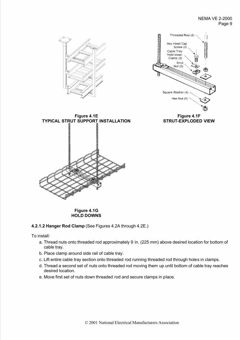
Figure 4.1ETYPICAL STRUT SUPPORT INSTALLATION
Figure 4.1FSTRUT-EXPLODED VIEW
Figure 4.1GHOLD DOWNS
4.2.1.2 Hanger Rod Clamp (See Figures 4.2A through 4.2E.)
To install:
a. Thread nuts onto threaded rod approximately 9 in. (225 mm) above desired location for bottom of cable tray.
b. Place clamp around side rail of cable tray.
c. Lift entire cable tray section onto threaded rod running threaded rod through holes in clamps.
d. Thread a second set of nuts onto threaded rod moving them up until bottom of cable tray reachesdesired location.
e. Move first set of nuts down threaded rod and secure clamps in place.

5/14/2018 Cable Tray Installation Nema Ve2 - slidepdf.com
http://slidepdf.com/reader/full/cable-tray-installation-nema-ve2 15/51
NEMA VE 2-2000Page 10
© 2001 National Electrical Manufacturers Association
Figure 4.2ASINGLE CABLE TRAY HANGER
Figure 4.2BDOUBLE CABLE TRAY HANGER
Figure 4.2CSINGLE CABLE TRAY HANGER
Figure 4.2DSINGLE CABLE TRAY HANGER
Figure 4.2ESINGLE CABLE TRAY HANGER

5/14/2018 Cable Tray Installation Nema Ve2 - slidepdf.com
http://slidepdf.com/reader/full/cable-tray-installation-nema-ve2 16/51
NEMA VE 2-2000
Page 11
© 2001 National Electrical Manufacturers Association
4.2.1.3 Center Hung Support (See Figures 4.3A and 4.3B)
To install:
a. Thread nut onto threaded rod approximately 9 in. (225 mm) above desired location for bottom of cable tray.
b. Slide washer and support onto threaded rod with upright tube going through center of cable traysection needing support.
c. Place a square washer on threaded rod and thread on second nut.
d. Move cross member so its top surface is located at the place where bottom of cable tray run willbe located.
e. Move second nut up threaded rod until it reaches cross member and holds it in place.
f. Move first nut down threaded rod until it secures cross member in place.
In most cases, hold-down/guide clamps may be mounted on either the inside or outside of the cable tray.When installed on the inside of the cable tray, the clamp and/or attaching hardware should not extendinto the cable pathway.
Figure 4.3ACENTER HANGER SUPPORT
Figure 4.3BCENTER HANGER SUPPORT
4.2.1.4 Single Channel Cable Tray Hanger (See Figure 4.4)
To install:
a. Thread nut onto threaded rod to height required.
b. Place hanger on threaded rod and follow with one nut.
c. Run nut up threaded rod until bottom of hanger is at desired height.
d. Run top nut down to tighten.
e. Place channel on hanger and secure in place as necessary.
5/14/2018 Cable Tray Installation Nema Ve2 - slidepdf.com
http://slidepdf.com/reader/full/cable-tray-installation-nema-ve2 17/51
NEMA VE 2-2000Page 12
© 2001 National Electrical Manufacturers Association
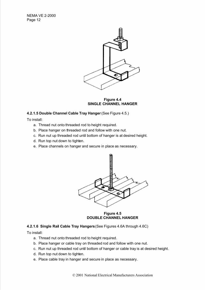
Figure 4.4SINGLE CHANNEL HANGER
4.2.1.5 Double Channel Cable Tray Hanger (See Figure 4.5.)
To install:
a. Thread nut onto threaded rod to height required.
b. Place hanger on threaded rod and follow with one nut.
c. Run nut up threaded rod until bottom of hanger is at desired height.
d. Run top nut down to tighten.
e. Place channels on hanger and secure in place as necessary.
Figure 4.5DOUBLE CHANNEL HANGER
4.2.1.6 Single Rail Cable Tray Hangers(See Figures 4.6A through 4.6C)
To install:
a. Thread nut onto threaded rod to height required.
b. Place hanger or cable tray on threaded rod and follow with one nut.
c. Run nut up threaded rod until bottom of hanger or cable tray is at desired height.
d. Run top nut down to tighten.
e. Place cable tray in hanger and secure in place as necessary.

5/14/2018 Cable Tray Installation Nema Ve2 - slidepdf.com
http://slidepdf.com/reader/full/cable-tray-installation-nema-ve2 18/51
NEMA VE 2-2000
Page 13
© 2001 National Electrical Manufacturers Association
Figure 4.6AMULTIPLE SPLICE SUPPORT
Figure 4.6BROD THROUGH SPINE HANGER
Figure 4.6CCLEVIS HANGER
4.2.2 Wall and Cantilever Brackets (See Figures 4.7A through 4.7E.)
Secure the brackets to the structure making sure they are level and aligned with each other.
Figure 4.7ASINGLE STRUT CANTILEVER BRACKET
Figure 4.7BGUSSET CANTILEVER BRACKET

5/14/2018 Cable Tray Installation Nema Ve2 - slidepdf.com
http://slidepdf.com/reader/full/cable-tray-installation-nema-ve2 19/51
NEMA VE 2-2000Page 14
© 2001 National Electrical Manufacturers Association
Figure 4.7CFIBERGLASS CANTILEVER BRACKET
Figure 4.7DSINGLE RAIL DIRECT WALL MOUNT
Figure 4.7ESINGLE RAIL CLAMP WALL MOUNT
4.2.3 Floor and Roof Installations (See Figures 4.8A through 4.8C.)
Cable tray should not be laid directly onthe floor or roof. It should be mountedfar enough off the floor or roof to allowthe cables to exit through the bottom of
the cable tray. If strut is used for this purpose,mount the strut directly to the floor or roof and attach the cable tray to the strut usinghold-down clamps and/or guide clamps.
Figure 4.8AELEVATED STRUT TYPE SUPPORT

5/14/2018 Cable Tray Installation Nema Ve2 - slidepdf.com
http://slidepdf.com/reader/full/cable-tray-installation-nema-ve2 20/51
NEMA VE 2-2000
Page 15
© 2001 National Electrical Manufacturers Association
Figure 4.8B Figure 4.8CUNDERFLOOR SUPPORT ATTACHED SINGLE RAIL FLOOR SUPPORT
TO FLOOR PEDESTALS
4.2.4 Vertical Applications (See Figures 4.9A through 4.9D.)
Figure 4.9A Figure 4.9BVERTICAL THREADED ROD SUPPORT VERTICAL GUSSET CANTILEVER SUPPORT
5/14/2018 Cable Tray Installation Nema Ve2 - slidepdf.com
http://slidepdf.com/reader/full/cable-tray-installation-nema-ve2 21/51
NEMA VE 2-2000Page 16
© 2001 National Electrical Manufacturers Association
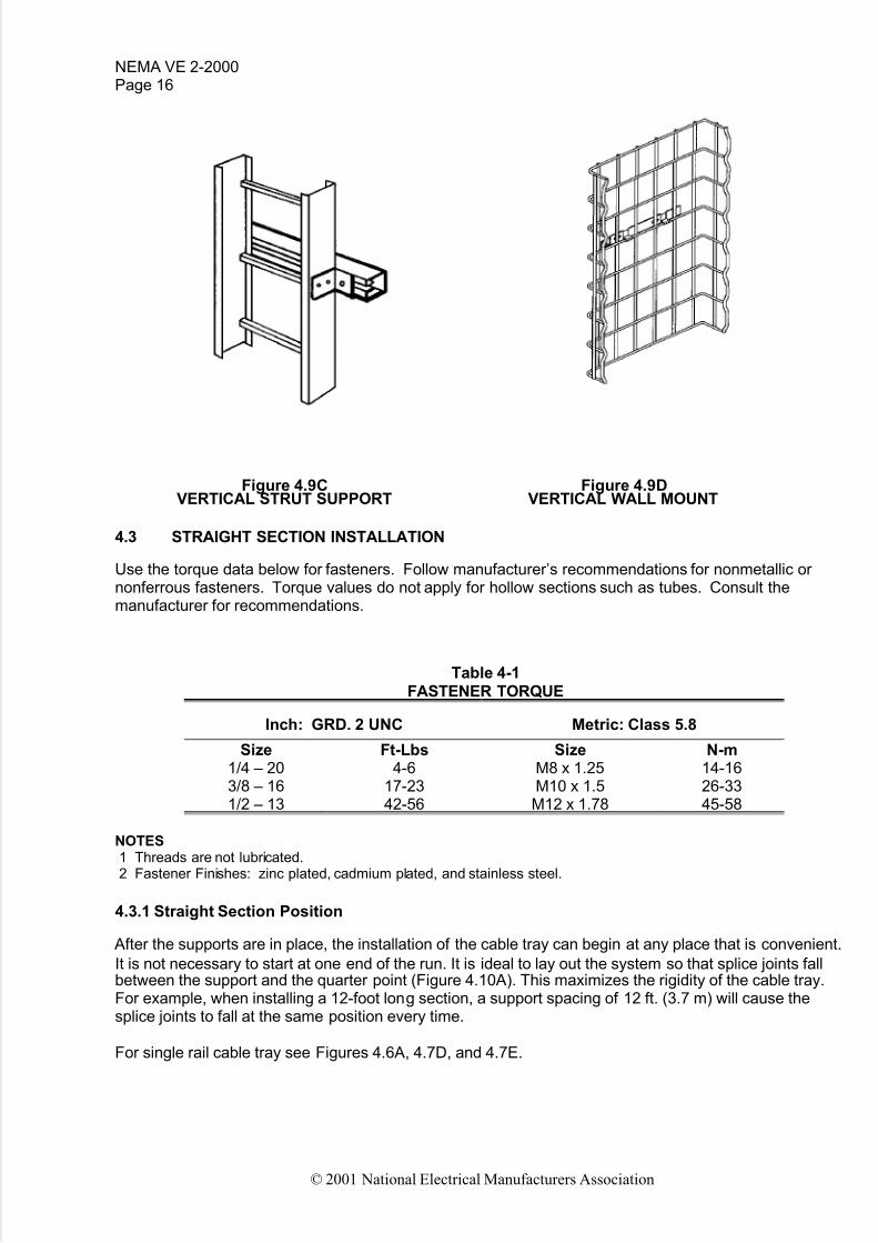
Figure 4.9C Figure 4.9DVERTICAL STRUT SUPPORT VERTICAL WALL MOUNT
4.3 STRAIGHT SECTION INSTALLATION
Use the torque data below for fasteners. Follow manufacturer’s recommendations for nonmetallic or nonferrous fasteners. Torque values do not apply for hollow sections such as tubes. Consult themanufacturer for recommendations.
Table 4-1FASTENER TORQUE
Inch: GRD. 2 UNC Metric: Class 5.8
Size1/4 – 203/8 – 161/2 – 13
Ft-Lbs4-6
17-2342-56
SizeM8 x 1.25M10 x 1.5M12 x 1.78
N-m14-1626-3345-58
NOTES1 Threads are not lubricated.2 Fastener Finishes: zinc plated, cadmium plated, and stainless steel.
4.3.1 Straight Section Position
After the supports are in place, the installation of the cable tray can begin at any place that is convenient.
It is not necessary to start at one end of the run. It is ideal to lay out the system so that splice joints fallbetween the support and the quarter point (Figure 4.10A). This maximizes the rigidity of the cable tray.For example, when installing a 12-foot long section, a support spacing of 12 ft. (3.7 m) will cause thesplice joints to fall at the same position every time.
For single rail cable tray see Figures 4.6A, 4.7D, and 4.7E.
5/14/2018 Cable Tray Installation Nema Ve2 - slidepdf.com
http://slidepdf.com/reader/full/cable-tray-installation-nema-ve2 22/51
NEMA VE 2-2000
Page 17
© 2001 National Electrical Manufacturers Association
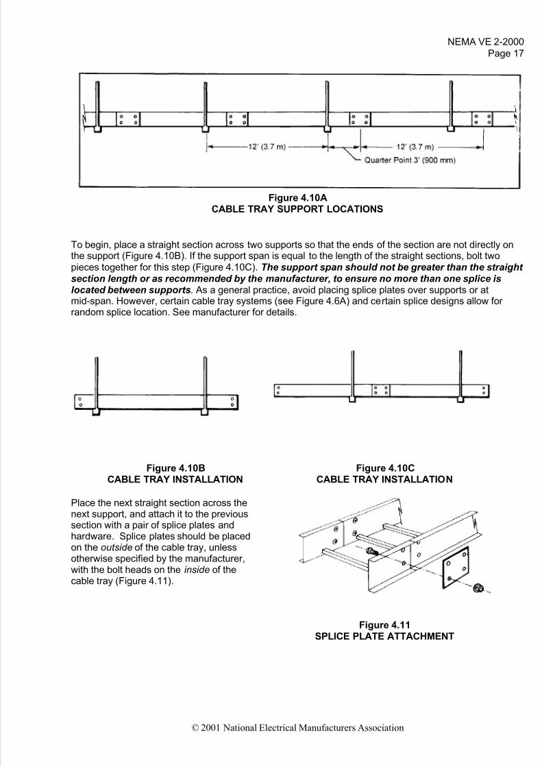
Figure 4.10ACABLE TRAY SUPPORT LOCATIONS
To begin, place a straight section across two supports so that the ends of the section are not directly onthe support (Figure 4.10B). If the support span is equal to the length of the straight sections, bolt twopieces together for this step (Figure 4.10C). The support span should not be greater than the straight section length or as recommended by the manufacturer, to ensure no more than one splice islocated between supports. As a general practice, avoid placing splice plates over supports or atmid-span. However, certain cable tray systems (see Figure 4.6A) and certain splice designs allow for random splice location. See manufacturer for details.
Figure 4.10B Figure 4.10CCABLE TRAY INSTALLATION CABLE TRAY INSTALLATION
Place the next straight section across thenext support, and attach it to the previoussection with a pair of splice plates andhardware. Splice plates should be placedon the outside of the cable tray, unlessotherwise specified by the manufacturer,with the bolt heads on the inside of thecable tray (Figure 4.11).
Figure 4.11SPLICE PLATE ATTACHMENT

5/14/2018 Cable Tray Installation Nema Ve2 - slidepdf.com
http://slidepdf.com/reader/full/cable-tray-installation-nema-ve2 23/51
NEMA VE 2-2000Page 18
© 2001 National Electrical Manufacturers Association
4.3.2 Expansion Splice Plates
It is important that thermal contractionand expansion be considered wheninstalling cable tray systems. Thelength of the straight cable tray runand the temperature differentialgovern the number of expansionsplice plates required (see Figure 4.12and Table 4-2).
Figure 4.12EXPANSION SPLICE PLATE ATTACHMENT
*Bonding jumper not required for fiberglass cable tray systems
Table 4-2MAXIMUM SPACING BETWEEN EXPANSION JOINTS
THAT PROVIDE FOR ONE INCH MOVEMENT**
Temperature Differential Steel Aluminum Fiberglass°F (°C) feet (m) feet (m) feet (m)
255075
100125150175
(14)(28)(42)(56)(70)(83)(97)
5122561711281028573
(156)(78)(52)(39)(31)(26)(22)
2601308765524337
(79)(40)(27)(20)(16)(13)(11)
66733322216713311195
(203)(102)(68)(51)(41)(34)(29)
* The temperature differential is the difference in the temperature between the hottest and coldest daysof the year.
** For designs that provide for 5/8 in. (16 mm) movement (typically non-metallic), multiply maximumspacing between expansion joints by 0.625.
The cable tray should be anchored at the support nearest to its midpoint between the expansion spliceplates and secured by expansion guides at all other support locations (see Figure 4.13A). The cable trayshould be permitted longitudinal movement in both directions from that fixed point.
Figure 4.13A
HOLD DOWN AND GUIDE CLAMP LOCATIONS
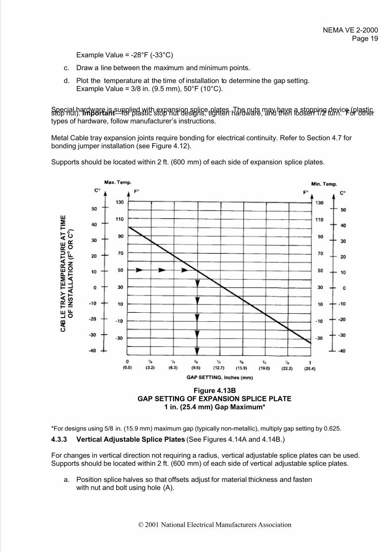
Accurate gap setting at the time of installation is necessary for the proper operation of theexpansion splice plates. The following procedure should assist the installer in determining thecorrect gap (see Figure 4.13B):
a. Plot the highest expected temperature on the maximum temperature line.Example Value = 100°F (38°C)
b. Plot the lowest expected temperature on the minimum temperature line.
5/14/2018 Cable Tray Installation Nema Ve2 - slidepdf.com
http://slidepdf.com/reader/full/cable-tray-installation-nema-ve2 24/51
NEMA VE 2-2000
Page 19
© 2001 National Electrical Manufacturers Association
Example Value = -28°F (-33°C)
c. Draw a line between the maximum and minimum points.
d. Plot the temperature at the time of installation to determine the gap setting.Example Value = 3/8 in. (9.5 mm), 50°F (10°C).
Special hardware is supplied with expansion splice plates. The nuts may have a stopping device (plasticstop nut). Important—for plastic stop nut designs, tighten hardware, and then loosen 1/2 turn. For other types of hardware, follow manufacturer’s instructions.
Metal Cable tray expansion joints require bonding for electrical continuity. Refer to Section 4.7 for bonding jumper installation (see Figure 4.12).
Supports should be located within 2 ft. (600 mm) of each side of expansion splice plates.
Figure 4.13BGAP SETTING OF EXPANSION SPLICE PLATE
1 in. (25.4 mm) Gap Maximum*
*For designs using 5/8 in. (15.9 mm) maximum gap (typically non-metallic), multiply gap setting by 0.625.
4.3.3 Vertical Adjustable Splice Plates (See Figures 4.14A and 4.14B.)
For changes in vertical direction not requiring a radius, vertical adjustable splice plates can be used.Supports should be located within 2 ft. (600 mm) of each side of vertical adjustable splice plates.
a. Position splice halves so that offsets adjust for material thickness and fastenwith nut and bolt using hole (A).
C A B L E T R A Y T E M P E R A T U R E A T T I M E
O F I N S T A L L A T I O N
( F o O
R
C o )

5/14/2018 Cable Tray Installation Nema Ve2 - slidepdf.com
http://slidepdf.com/reader/full/cable-tray-installation-nema-ve2 25/51
NEMA VE 2-2000Page 20
© 2001 National Electrical Manufacturers Association
b. Attach to positioned cable tray sections which will set needed angle.
c. Drill to complete hole (B). Figure 4.14A only.
d. Insert and tighten all hardware.
For metal cable tray, bonding jumpers are required for electrical continuity, unless the splice plates meet
the electrical continuity requirements of NEMA Standard VE 1. (Refer to Section 4.7 - Grounding)
Figure 4.14A Figure 4.14BTWO BOLT VERTICAL ADJUSTABLE SINGLE BOLT VERTICAL ADJUSTABLE
SPLICE PLATES SPLICE PLATES
4.3.4 Horizontal Adjustable Splice Plates (See Figure 4.15.)
For changes in horizontal direction notrequiring a radius, horizontal adjustablesplice plates can be used. Supports shouldbe located within 2 ft. (600 mm) of each side
of horizontal adjustable splice plates.a. Connect inside connector (short piece)
and position cable tray sections to set angle.b. Position outside connector locating hinge
at mid-point.c. Drill required holes and install and tighten all
hardware.For metal cable tray, bonding jumpers are required for electrical continuity unless the splice plates meetthe electrical continuity requirements of NEMAStandard VE 1 (Refer to Section 4.7 - Grounding).
Figure 4.15HORIZONTAL ADJUSTABLE
SPLICE PLATES

5/14/2018 Cable Tray Installation Nema Ve2 - slidepdf.com
http://slidepdf.com/reader/full/cable-tray-installation-nema-ve2 26/51
NEMA VE 2-2000
Page 21
© 2001 National Electrical Manufacturers Association
4.3.5 Cable Tray-to-Box or Floor Splice Plates (See Figures 4.16A and 4.16B)
For termination of cable tray system to equipment or structures:
Cable trays and/or cable penetrations through partitions, walls, floors, and ceilings often require specialfire rating or environmental concerns and should be handled in accordance with NEC
®Articles 318 and
300.
Figure 4.16A Figure 4.16BCABLE TRAY-TO-BOX/FLOOR SPLICE PLATES CABLE TRAY-TO-BOX CONNECTOR
4.3.6 Offset Reducing Splice Plates (See Figure 4.17.)
For immediate width changes, use offsetreducing splice plates. Supports should be
located within 2 ft. (600 mm) of each side of offset reducing splice plates.
a. Use an offset reducing splice plate with astandard splice plate to form an offsetreduction.
b. Use a pair of offset reducing splice platesto form a straight reduction.
Figure 4.17OFFSET REDUCING SPLICE PLATE

5/14/2018 Cable Tray Installation Nema Ve2 - slidepdf.com
http://slidepdf.com/reader/full/cable-tray-installation-nema-ve2 27/51
NEMA VE 2-2000Page 22
© 2001 National Electrical Manufacturers Association
4.3.7 Vertical Support Plates (See Figure4.18.)
Use vertical support splice plates for additionalsupport of extended vertical runs. (See Section4.2.4)
Figure 4.18VERTICAL SUPPORT PLATES
4.3.8 Step-down Splice Plates (See Figure 4.19.)
Use step-down splice plates when connecting cabletrays of different heights.
Figure 4.19
STEP-DOWN SPLICE PLATES
4.3.9 End Plates (See Figure 4.20.)
For dead-end closure indicating termination of cable tray run use end plates.
Figure 4.20END PLATE
5/14/2018 Cable Tray Installation Nema Ve2 - slidepdf.com
http://slidepdf.com/reader/full/cable-tray-installation-nema-ve2 28/51
NEMA VE 2-2000
Page 23
© 2001 National Electrical Manufacturers Association
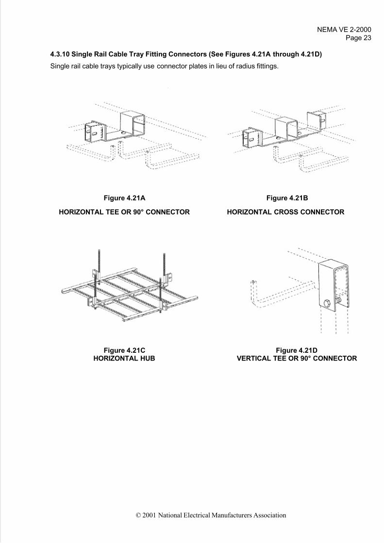
4.3.10 Single Rail Cable Tray Fitting Connectors (See Figures 4.21A through 4.21D)
Single rail cable trays typically use connector plates in lieu of radius fittings.
Figure 4.21A Figure 4.21B
HORIZONTAL TEE OR 90° CONNECTOR HORIZONTAL CROSS CONNECTOR
Figure 4.21C Figure 4.21DHORIZONTAL HUB VERTICAL TEE OR 90° CONNECTOR
5/14/2018 Cable Tray Installation Nema Ve2 - slidepdf.com
http://slidepdf.com/reader/full/cable-tray-installation-nema-ve2 29/51
NEMA VE 2-2000Page 24
© 2001 National Electrical Manufacturers Association
4.4 FITTINGS INSTALLATION (See Section 4.4.3 for single rail and wire mesh cable trays)
4.4.1 Recommended Support Locations for Fittings(unless otherwise recommended by the manufacturer)
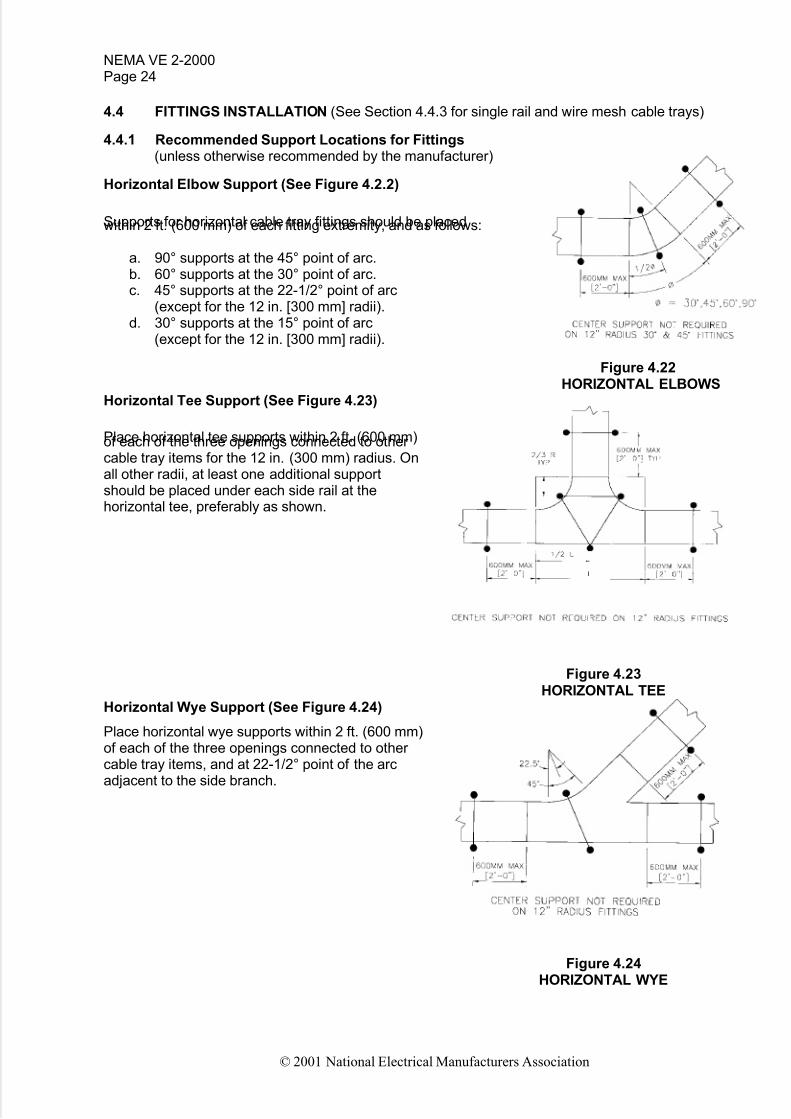
Horizontal Elbow Support (See Figure 4.2.2)
Supports for horizontal cable tray fittings should be placedwithin 2 ft. (600 mm) of each fitting extremity, and as follows:
a. 90° supports at the 45° point of arc.b. 60° supports at the 30° point of arc.c. 45° supports at the 22-1/2° point of arc
(except for the 12 in. [300 mm] radii).d. 30° supports at the 15° point of arc
(except for the 12 in. [300 mm] radii).
Figure 4.22HORIZONTAL ELBOWS
Horizontal Tee Support (See Figure 4.23)
Place horizontal tee supports within 2 ft. (600 mm)of each of the three openings connected to other cable tray items for the 12 in. (300 mm) radius. Onall other radii, at least one additional supportshould be placed under each side rail at thehorizontal tee, preferably as shown.
Figure 4.23HORIZONTAL TEE
Horizontal Wye Support (See Figure 4.24)
Place horizontal wye supports within 2 ft. (600 mm)of each of the three openings connected to other cable tray items, and at 22-1/2° point of the arcadjacent to the side branch.
Figure 4.24HORIZONTAL WYE

5/14/2018 Cable Tray Installation Nema Ve2 - slidepdf.com
http://slidepdf.com/reader/full/cable-tray-installation-nema-ve2 30/51
NEMA VE 2-2000
Page 25
© 2001 National Electrical Manufacturers Association
Horizontal Cross Support (See Figure 4.25)
Place horizontal cross support within 2 ft. (600 mm)of each of the four openings connected to other cable tray items for the 12 in. (300 mm) radius. Onall other radii, at least one additional supportshould be placed under each side rail of the
horizontalcross, preferably as shown.
Figure 4.25HORIZONTAL CROSS
Reducer Support (See Figure 4.26)
Place reducer supports within 2 ft. (600 mm) of each fitting extremity.
Figure 4.26REDUCER
Vertical Cable Tray Elbows (See Figure 4.27) Vertical cable tray elbows at the top of runsshould be supported at each end. At the bottomof runs, they should be supported at the top of theelbow and within 2 ft. (600 mm) of the lower extremity of the elbows.
Figure 4.27VERTICAL ELBOWS
(Side View)

5/14/2018 Cable Tray Installation Nema Ve2 - slidepdf.com
http://slidepdf.com/reader/full/cable-tray-installation-nema-ve2 31/51
NEMA VE 2-2000Page 26
© 2001 National Electrical Manufacturers Association
Vertical Cable Tray Tees (See Figure 4.28)
Vertical cable tray tees should be supported within2 ft. (600 mm) of each fitting extremity.
Figure 4.28VERTICAL TEE
(Side View)
4.4.2 Cable Support Fitting (See Figures 4.29 and 4.30.)
These fittings are recommended for use at the top of long vertical runs of heavy cable to support thecables.
Figure 4.29 Figure 4.30VERTICAL CABLE SUPPORT VERTICAL CABLE SUPPORT
4.4.3 Recommended Support Locations for Single Rail and Wire Mesh Cable Trays
Single rail and wire mesh cable trays have alternate support configurations. Consult manufacturer for details.
4.5 FIELD MODIFICATIONS
Eventually it will be necessary to field cut the cable tray because the length of the cable tray required willbe less than standard length. If there are many cuts to be made in a given area, waste can be preventedby making a cut list, which can be used to calculate the most efficient use of the standard sections.
Cable tray field modifications shall be made by qualified personnel only.4.5.1 Marking (See Figures 4.31and 4.32)
5/14/2018 Cable Tray Installation Nema Ve2 - slidepdf.com
http://slidepdf.com/reader/full/cable-tray-installation-nema-ve2 32/51
NEMA VE 2-2000
Page 27
© 2001 National Electrical Manufacturers Association
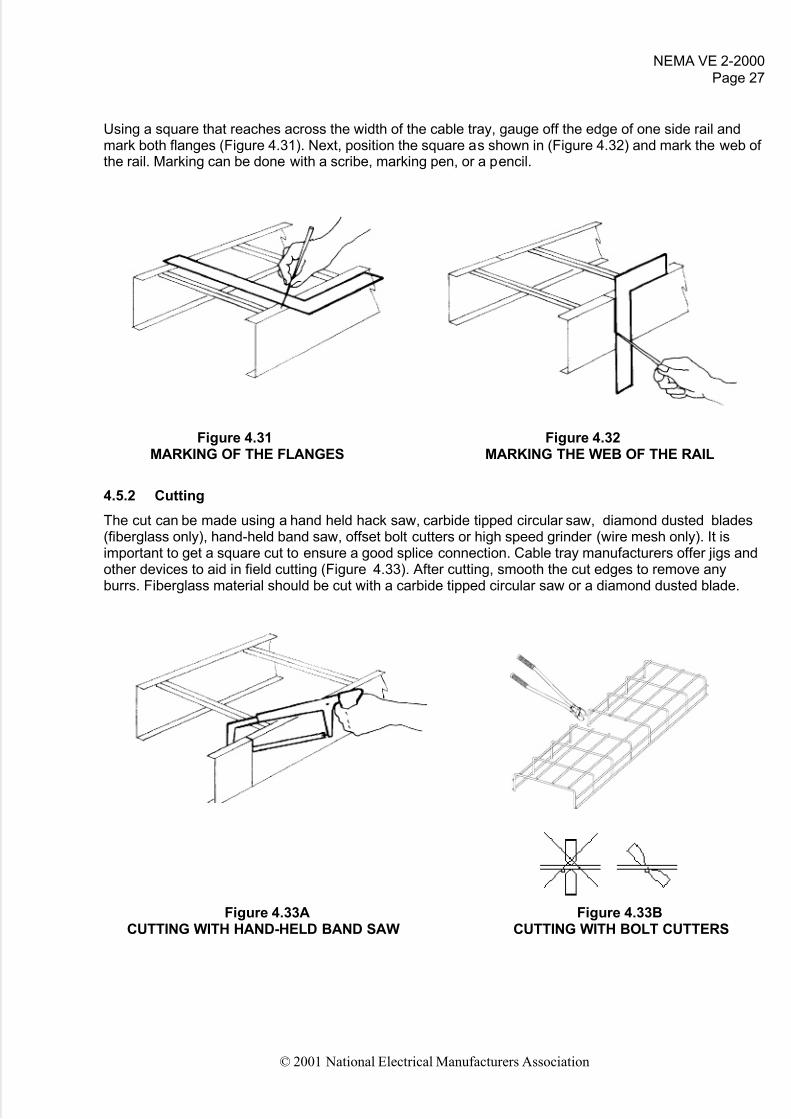
Using a square that reaches across the width of the cable tray, gauge off the edge of one side rail andmark both flanges (Figure 4.31). Next, position the square as shown in (Figure 4.32) and mark the web of the rail. Marking can be done with a scribe, marking pen, or a pencil.
Figure 4.31 Figure 4.32MARKING OF THE FLANGES MARKING THE WEB OF THE RAIL
4.5.2 Cutting
The cut can be made using a hand held hack saw, carbide tipped circular saw, diamond dusted blades(fiberglass only), hand-held band saw, offset bolt cutters or high speed grinder (wire mesh only). It isimportant to get a square cut to ensure a good splice connection. Cable tray manufacturers offer jigs andother devices to aid in field cutting (Figure 4.33). After cutting, smooth the cut edges to remove anyburrs. Fiberglass material should be cut with a carbide tipped circular saw or a diamond dusted blade.
Figure 4.33A Figure 4.33BCUTTING WITH HAND-HELD BAND SAW CUTTING WITH BOLT CUTTERS

5/14/2018 Cable Tray Installation Nema Ve2 - slidepdf.com
http://slidepdf.com/reader/full/cable-tray-installation-nema-ve2 33/51
NEMA VE 2-2000Page 28
© 2001 National Electrical Manufacturers Association
4.5.3 Drilling (See Figures 4.34 through 4.36.)
Holes for splice plates must be drilled in field-cut cable trays. The most common method of locating thehole positions is to use a splice plate as a template. Drill jigs (Figure 4.34) are also available. A short pieceof side rail that is punched with the standard factory hole pattern can be bolted to the splice plate to serveas a stop that rests against the end of the field-cut side rail (Figure 4.35). Clamp the splice plate to the railand drill through the splice plate holes and the side rail (Figure 4.36). The correct drill size is dependent on
the hardware supplied with the cable tray. Match the holes that exist in the cable tray. After drilling, removeburrs.
Figure 4.34 Figure 4.35 Figure 4.36DRILLING WITH USE OF DRILLING WITH USE OF DRILLING WITH USE OF
DRILL JIGS PUNCHED SIDE RAIL CLAMP AND SIDE RAIL
4.5.4 Finish Touch Up
Cable trays that have a hot dip galvanized coating applied after fabrication need to be retouched after cutting, drilling, or deburring or if the coating gets damaged. These cutting operations leave bare metaledges that will begin to corrode immediately. Cable trays made from mill galvanized steel do not need to
be touched up because they are not designed to be used in heavily corrosive atmospheres and havebare metal edges inherent in their design. Aluminum cable trays do not need to be touched up.
Touch up of the galvanized finish must be done according to ASTM A 780, Repair of Damaged Hot-DipGalvanized Coatings. Use an approved zinc-rich galvanizing material that meets the requirements of
ASTM A 780. If it is not noted on the product label as to whether the material meets ASTM A 780, thematerial specification sheet should be obtained from the galvanizing material supplier. The paint can beapplied by brushing or spraying. Always paint 1/2 in. (13 mm) to 1 in. (25 mm) beyond the bare area toprevent undercutting by corrosion.
After cutting of fiberglass cable trays, seal cut edges with manufacturer’s recommended sealant.
Other protective coatings that are cut or damaged must be touched up with compatible coatings.
4.5.5 Wire Mesh Fittings Fabrication
Fittings are field fabricated from straight sections on-site with an offset bolt cutter and wrench, or highspeed grinder.
Horizontal or vertical bends, tees, and crosses are fabricated by notching out segments of side rail gridsand overlapping and connecting parallel wires by means of a connector.

5/14/2018 Cable Tray Installation Nema Ve2 - slidepdf.com
http://slidepdf.com/reader/full/cable-tray-installation-nema-ve2 34/51
NEMA VE 2-2000
Page 29
© 2001 National Electrical Manufacturers Association
Figure 4.38TYPICAL WIRE MESH FITTINGS—FIELD FABRICATED
4.6 ACCESSORIES
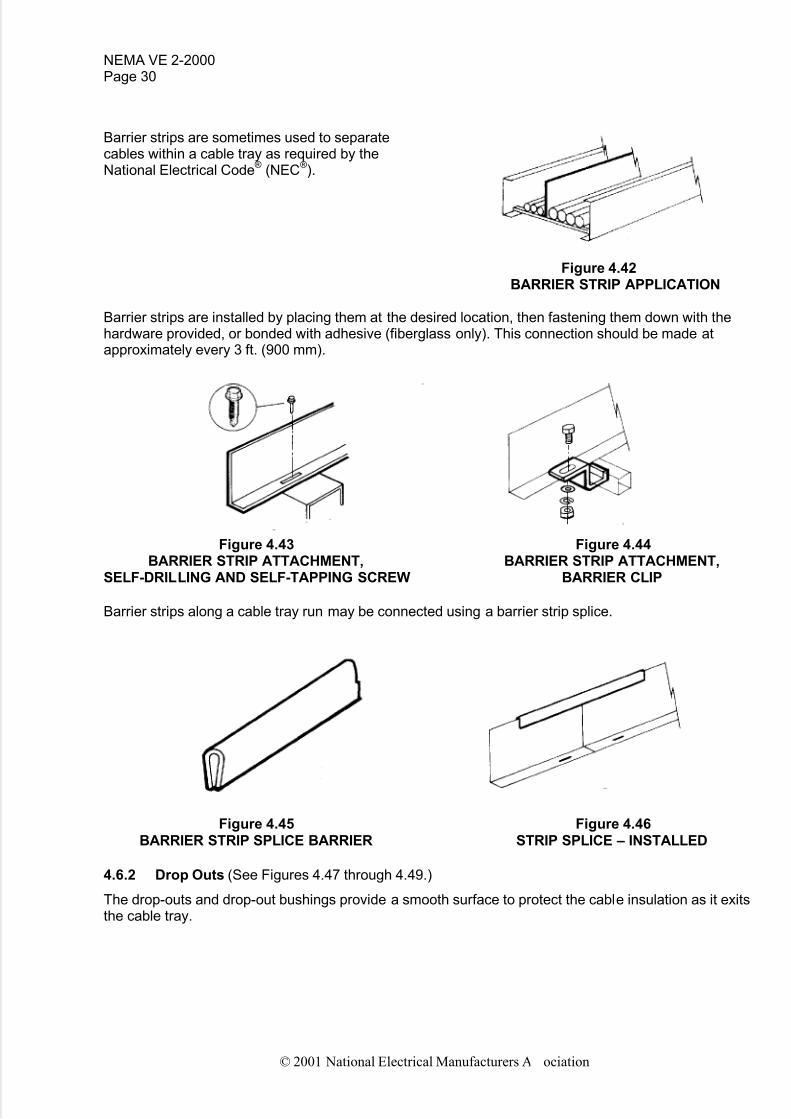
4.6.1 Barrier Strips (See Figures 4.39 through 4.46.)
Figure 4.39 Figure 4.40 Figure 4.41BARRIER STRIP– BARRIER STRIP– BARRIER STRIP–
STRAIGHT SECTION HORIZONTAL FITTING VERTICAL FITTING
5/14/2018 Cable Tray Installation Nema Ve2 - slidepdf.com
http://slidepdf.com/reader/full/cable-tray-installation-nema-ve2 35/51
NEMA VE 2-2000Page 30
© 2001 National Electrical Manufacturers Association
Barrier strips are sometimes used to separatecables within a cable tray as required by theNational Electrical Code
®(NEC
®).
Figure 4.42BARRIER STRIP APPLICATION
Barrier strips are installed by placing them at the desired location, then fastening them down with thehardware provided, or bonded with adhesive (fiberglass only). This connection should be made atapproximately every 3 ft. (900 mm).
Figure 4.43 Figure 4.44BARRIER STRIP ATTACHMENT, BARRIER STRIP ATTACHMENT,
SELF-DRILLING AND SELF-TAPPING SCREW BARRIER CLIP
Barrier strips along a cable tray run may be connected using a barrier strip splice.
Figure 4.45 Figure 4.46BARRIER STRIP SPLICE BARRIER STRIP SPLICE – INSTALLED
4.6.2 Drop Outs (See Figures 4.47 through 4.49.)
The drop-outs and drop-out bushings provide a smooth surface to protect the cable insulation as it exitsthe cable tray.

5/14/2018 Cable Tray Installation Nema Ve2 - slidepdf.com
http://slidepdf.com/reader/full/cable-tray-installation-nema-ve2 36/51
NEMA VE 2-2000
Page 31
© 2001 National Electrical Manufacturers Association
Figure 4.47 Figure 4.48 Figure 4.49LADDER DROP-OUT TROUGH DROP-OUT 4TROUGH DROP-OUT BUSHING
4.6.3 Cable Channel-to-Cable Tray
Figure 4.50 Figure 4.51TRAY TO CHANNEL CHANNEL TO LADDER TRAY BRACKET
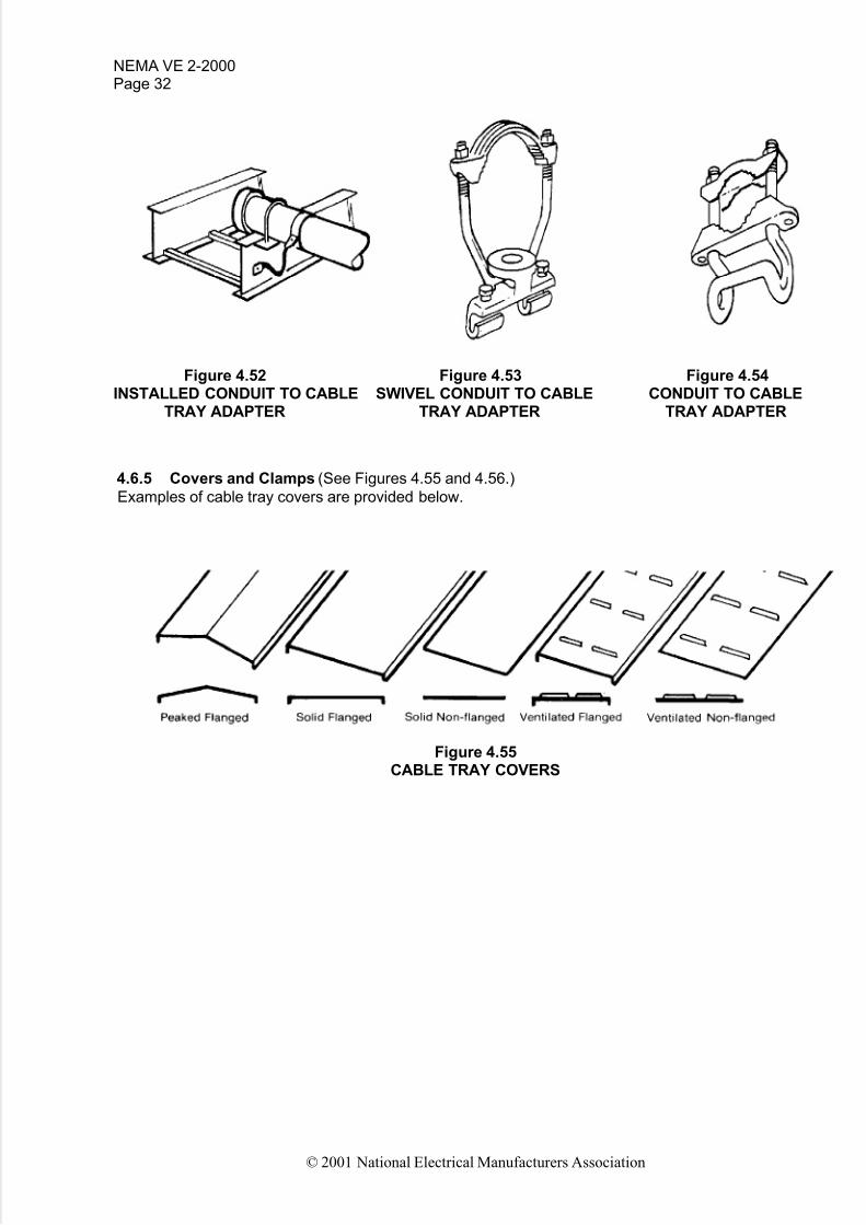
4.6.4 Conduit-to-Cable Tray Adaptors (See Figures 4.52 through 4.54.)
These adaptors provide for attachment of conduit that terminates at a cable tray run. If a connector is notUL listed, it only provides a mechanical connection, not an electrical connection. In order to make anelectrical connection, an equipment grounding conductor must be run from the conduit to the cable tray.
5/14/2018 Cable Tray Installation Nema Ve2 - slidepdf.com
http://slidepdf.com/reader/full/cable-tray-installation-nema-ve2 37/51
NEMA VE 2-2000Page 32
© 2001 National Electrical Manufacturers Association
Figure 4.52 Figure 4.53 Figure 4.54INSTALLED CONDUIT TO CABLE SWIVEL CONDUIT TO CABLE CONDUIT TO CABLE
TRAY ADAPTER TRAY ADAPTER TRAY ADAPTER
4.6.5 Covers and Clamps (See Figures 4.55 and 4.56.)
Examples of cable tray covers are provided below.
Figure 4.55CABLE TRAY COVERS

5/14/2018 Cable Tray Installation Nema Ve2 - slidepdf.com
http://slidepdf.com/reader/full/cable-tray-installation-nema-ve2 38/51
NEMA VE 2-2000
Page 33
© 2001 National Electrical Manufacturers Association
Figure 4.56CABLE TRAY COVER CLAMPS AND ACCESSORIES
NOTE—Special consideration should be given in regards to wind loading for outdoor applications.
Table 4-3 provides information on the required spacing for cover clamps
Table 4-3QUANTITY OF STANDARD COVER CLAMPS REQUIRED
Straight section, 6 ft. (1.8 m)Straight section, 10 ft. (3.0 m) and 12 ft. (3.7 m)Horizontal/vertical bendsTeesCrosses
4 pieces6 pieces4 pieces6 pieces8 pieces
NOTE—When using the heavy duty cover clamp shown in Figure 4.56e, only half the quantity of pieces are required.

5/14/2018 Cable Tray Installation Nema Ve2 - slidepdf.com
http://slidepdf.com/reader/full/cable-tray-installation-nema-ve2 39/51
NEMA VE 2-2000Page 34
© 2001 National Electrical Manufacturers Association
4.7 GROUNDING AND BONDING
Metal cable trays must be grounded and electrically continuous systems per NEC Article 318. For specificareas requiring bonding for electrical continuity, refer to Figures 4.57 through 4.60.
NOTE—Non-metallic cable trays do not serve as a conductor.
NOTE—It is recommended that wire mesh cable trays not be used as an equipment grounding conductor.
4.7.1 Cable Tray Used as an Equipment Ground Conductor (EGC) (See Figures 4.57 through 4.60)
The use of aluminum and steel cable trays is permitted as an Equipment Grounding Conductor per NEC Article 318 when labeled and marked with the available cross sectional area. (See Table 4-4.) If thecable tray is to be used as an EGC, bonding jumpers must be installed on both side rails at the locationsillustrated in Figures 4.57 through 4.60, unless the splice plates meet the electrical continuityrequirements of NEMA VE 1. See Table 4-5 for minimum sizes of grounding conductors.
NOTE—Although permitted by the NEC, it is recommended due to the unique nature of the product, fittings aremanufactured in the field from straight sections by cutting away the current carrying structural wires, reducing thecurrent-carrying capability of the system. As such, the use of wire mesh cable trays as an equipment groundingconductor is not recommended.
Figure 4.57 Figure 4.58EXPANSION SPLICE PLATES HORIZONTAL ADJUSTABLE SPLICE PLATES
Figure 4.59CABLE TRAY SECTIONS VERTICAL ADJUSTABLE
SPLICE PLATE
Figure 4.60DISCONTINUOUS

5/14/2018 Cable Tray Installation Nema Ve2 - slidepdf.com
http://slidepdf.com/reader/full/cable-tray-installation-nema-ve2 40/51
NEMA VE 2-2000
Page 35
© 2001 National Electrical Manufacturers Association
It is not necessary to install bonding jumpers at standard rigid aluminum or galvanized steel splice plateconnections or offset reducing splice plate connections.
For rigid splice plate connections of materials and finishes other than aluminum or galvanized steel, bonding jumpers may be required. For example, stainless steel splice plates require bonding jumpers.
4.7.2 Cable Trays with Separate Equipment Grounding Conductor Installed(See Figure 4.61.)When a separate EGC cable is installed in or on cable tray, it may be bonded to the cable tray with agrounding clamp. Ground clamp styles include bolted lug types that require drilling the cable tray side railand clamp-on styles that work like a beam clamp. One grounding clamp should be used on each straightsection of cable tray.
Figure 4.61GROUNDING CLAMPS
Bare copper EGC cable should not be used in or on aluminum cable tray. Bonding jumpers are notrequired if the separate EGC is properly bonded to all equipment.
4.7.3 Check for Properly Sized EGC or Bonding Jumpers
4.7.3.1 Power Applications
Bonding jumpers or separate EGC shall be sized according to NEC Articles 250 and 318. Note that NECTable 318-7(b)(2) is the actual circuit breaker trip setting and not the maximum allowable. If the maximumampere rating of the cable tray is not sufficient for the protective device to be used, the cable tray cannotbe used as an EGC, and a separate EGC must be included in each cable or attached to the cable tray.
National Electrical Code and NEC are registered trademarks of the National Fire Protection Association,Inc., Quincy, MA 02269. Reprinted with permission from NFPA 70-1999, the National Electrical Code,Copyright 1998, National Fire Protection Association, Quincy, MA 02269. This reprinted material is notthe complete and official position of the National Fire Protection Association, on the referenced subject,which is represented only by the standard in its entirety.

5/14/2018 Cable Tray Installation Nema Ve2 - slidepdf.com
http://slidepdf.com/reader/full/cable-tray-installation-nema-ve2 41/51
NEMA VE 2-2000Page 36
© 2001 National Electrical Manufacturers Association
4.7.3.2 Non-Power Applications
Cable tray systems containing conductors outside the scope of NEC Article 250 (such ascommunications, data, signal cables, etc.) still require proper bonding and grounding for system operationand performance.
Metal trays containing these conductors shall be electrically continuous, via listed connectors or the use
of an insulated #10 (minimum) stranded bonding jumper.
Electrical continuity across field fabricated wire mesh fittings can be accomplished using listed wire meshtray connectors and following manufacturer’s installation instructions.
4.7.3.3 Mixed Systems
When power conductors are installed in metallic cable tray with non-power conductors, the bonding andgrounding requirements shall be as in 4.7.3.1.
NOTE—Power and non-power cables should be separated with a fixed metal barrier.
Table 4-4METAL AREA REQUIREMENTS FOR CABLE TRAYS
USED AS EQUIPMENT GROUNDING CONDUCTORS (NEC TABLE 318-7(B)(2))
Minimum Cross-Sectional Areaof Metal* in square Inches
Maximum Fuse Ampere Rating,Circuit Breaker Ampere Trip Setting or Circuit Breaker
Protective Relay Ampere Trip Setting
for Ground-Fault Protection of any Cable Circuit In theCable Tray System
Steel
Cable Trays
Aluminum
Cable Trays
60100200
4006001000120016002000
0.200.400.70
1.001.50**--------
0.200.200.20
0.400.400.601.001.502.00**
For Sl units: 1 square inch = 645 square millimeters.* Total cross-sectional area of both side rails for ladder or trough cable trays or the minimum
cross-sectional area of metal in channel cable trays or cable trays of one-piece construction.** Steel cable trays shall not be used as equipment grounding conductors for circuits with ground-fault
protection above 600 amperes. Aluminum cable trays shall not be used as equipment groundingconductors for circuits with ground-fault protection above 2000 amperes.
NOTE—See Section 4.7.3.1 to select separate EGC.

5/14/2018 Cable Tray Installation Nema Ve2 - slidepdf.com
http://slidepdf.com/reader/full/cable-tray-installation-nema-ve2 42/51
NEMA VE 2-2000
Page 37
© 2001 National Electrical Manufacturers Association
Table 4-5MINIMUM SIZE EQUIPMENT GROUNDING CONDUCTORS
FOR GROUNDING RACEWAY AND EQUIPMENT (NEC TABLE 250-122)
Wire Size
AWG or kcmilRating or Setting of Automatic
Overcurrent Device in Circuit Ahead of
Equipment, Conduit, etc.Not Exceeding
(Amperes) Copper Wire Size
Aluminum or
Copper-CladAluminum
1520304060
100200300
400500600800
100012001600200025003000400050006000
14 AWG12101010864
321
1/02/03/04/0
250 kcmil350400500700800
12 AWG10888642
11/02/03/04/0
250 kcmil350400600600800
12001200
*See installation restrictions in NEC Article 250.
4.7.4 How To Install Bonding Jumpers (See Figure 4.62.)
Types of typical jumpers (always size jumpers to meet above NEC tables) include insulated, bare, andbraided or laminated.
Figure 4.62BONDING JUMPERS

5/14/2018 Cable Tray Installation Nema Ve2 - slidepdf.com
http://slidepdf.com/reader/full/cable-tray-installation-nema-ve2 43/51
NEMA VE 2-2000Page 38
© 2001 National Electrical Manufacturers Association
Drill holes in side rail 2 in. (50 mm) from each end of the splice plate so the jumper will span thediscontinuity. Do not use splice plate bolt locations to connect jumper to cable tray.
Place screw head on inside of cable tray, put jumper on outside of cable tray, add flat washer, andlocknut, and tighten.
4.8 BONDING TO BUILDING STEEL AND EARTH
Metallic cable trays shall be bonded to building steel and earth as supplemental grounding for groundfault protection and signal grounding (“noise” prevention). The tray shall be bonded to building steel andearth, at least every 60 ft. This is only required when the cable tray system is not inherently bonded(connected) to building steel and earth through metallic support systems.

5/14/2018 Cable Tray Installation Nema Ve2 - slidepdf.com
http://slidepdf.com/reader/full/cable-tray-installation-nema-ve2 44/51
NEMA VE 2-2000
Page 39
© 2001 National Electrical Manufacturers Association
Section 5
INSTALLATION OF CABLE
The text of this section has been provided by NEMA wire and cable manufacturers. The Metal andNonmetallic Cable Tray Section hereby acknowledges the Wire and Cable Section’s cooperation andcontribution.
5.1 GENERAL
This section offers some general guidelines or rules of thumb on the installation of cable in cable tray.This information is not intended to replace the recommendations of the cable manufacturer. Themanufacturer of the product is the best source for information on the product, its use, and installationpractices.
5.2 HANDLING AND STORAGE
To avoid personal injury or damage to the cable and reels, follow guidelines below on handling andstorage of cable upon receipt at the job site.
a. Inspect all reels upon receipt for proper material and any type of damage. Be sure to note anydamage on the receiving papers.
b. Do not allow the reels to drop from the delivery truck during the unloading process. When a forkliftis used, the forks must support both reel flanges. Reels can be hoisted by lifting on a metal shaft of sufficient size and strength placed through the center hole of the reel. Handling equipment must notcome in contact with the cable.
c. Reels may be marked with a directional arrow and phrase such as "Roll This Way" to indicate theproper direction to roll the reel. Reels should only be rolled in the direction shown, or in thedirection opposite to the direction that the cable is wrapped on the reel. Rolling reels in the wrongdirection can cause the cable to loosen on the reel, which may cause problems during cable de-
reeling or installation. Do not allow reels to roll uncontrolled as they may roll into objects, damagingthe cable or causing personal injury. When rolling reels down inclines, the incline should be asgradual as possible, and control of the reel must be maintained.
d. Use care when choosing a location for cable storage. The temperature of the storage locationshould be 14°F (-10°C) or higher. Select an area that is remote from construction activity, wherethe cable will be protected from equipment, falling objects, excessive heat, or cold, chemicals, etc.,resulting in potential damage. Cable reels should be stored indoors on a dry surface or, if storedoutdoors, placed on suitable dunnage of sufficient size to support the reel weight without sinking or allowing the reels to come in contact with moisture. Reels stored outside (prior to and after installation) should be covered with weatherproof material to protect reels and cable from sunlightand moisture, and cable ends must be kept sealed and should remain fastened to the reel flange toprevent them from laying on the ground. Reels should never be stored or stacked on their sides.
Store reels on their flanges, properly chocked to prevent rolling. Be sure to allow enough roombetween reels to allow access to the reels for removal.
5.3 CABLE TRAY PREPARATION
Prior to installing cable in the cable tray, examine cable paths to ensure all areas are free of debris thatmay interfere with the cable's installation. The cable tray should never be used as a walkway.
5.4 CABLE PULLING CONSIDERATIONS (See Figure 5.1)
Most cable installations require the use of cable pulling tools.

5/14/2018 Cable Tray Installation Nema Ve2 - slidepdf.com
http://slidepdf.com/reader/full/cable-tray-installation-nema-ve2 45/51
NEMA VE 2-2000Page 40
© 2001 National Electrical Manufacturers Association
a. On horizontal straight runs, the cables generally ride on rollers mounted in or on the cable tray(See Figure 5.4). These rollers should be properly spaced dependent on the size and weight of the cable to prevent the cable from sagging and dragging in the cable tray during the pull. Contactthe cable manufacturer for information regarding proper roller spacing.
b. On horizontal bends and vertical pulls, the cables are generally run through pulleys or sheaves tomaintain a minimum bending radius (See Figures 5.5 and 5.6). Pulleys and sheaves must be of sufficient diameter to prevent pinching the cable between the pulley flanges. Each cable will havea minimum bending radius that must be maintained to prevent damage to the cable. Contact thecable manufacturer for the proper minimum bending radius. Multiple pulling tools may be requiredat one bend to maintain this radius. Be careful with the entry and exit angle of the cable at thepulling tool, as this angle can exceed the bending radius.
c. Due to the length of some cable pulls and the cable weight, a great deal of force can be applied tothe pulleys on horizontal and vertical bends. These pulleys should be anchored to the structuralsteel and not to the cable tray due to the force that can be applied during pulling. Do not pull downon the horizontal rollers, as they are not designed for this purpose, and damage could result to thecable or cable tray.
Figure 5.1
CABLE INSTALLATION
5.5 PULLING THE CABLE
Larger cables will usually require a basket grip and/or pulling eye to be attached to the leading end of thecables metallic conductor(s). If your cable does not have a pulling eye attached by the manufacturer,contact the cable manufacturer for information on field installation of a pulling eye and/or basket grip (seeFigures 5.2 and 5.3). Where pulling attachments are used on the conductors, cover them with rubber-likeor plastic tapes to prevent scoring of the cable trays and installation sheaves during a conductor pull. Thereel will generally be placed on reel jacks with an axle of sufficient size and strength to allow the reel to

5/14/2018 Cable Tray Installation Nema Ve2 - slidepdf.com
http://slidepdf.com/reader/full/cable-tray-installation-nema-ve2 46/51
NEMA VE 2-2000
Page 41
© 2001 National Electrical Manufacturers Association
turn freely with a minimum of friction. Since cables have pulling tension restrictions, a dynamometer maybe installed at the pulling end and the readings recorded with every pull to assure that the cable’smaximum pulling tension is not exceeded. Communications should be established between the pullingend of the run and the reel end of the run. The cable should be pulled at a constant speed during the pull.Contact the cable manufacturer for maximum pulling tension and cable pulling speed. Be sure to haveadequate personnel available at the reel end to aid in feeding the cable, watching to prevent cables from
getting crossed and for reel braking if necessary. Be sure to pull enough cable to allow for removal of pulling eyes or basket grips and resealing of the cable ends and connections. Once the cable is installed,the cable must be removed from the pulling devices and laid in the cable tray. Do not allow the cables todrop in the cable tray as this may damage the cable and/or the cable tray. If cable connections will not bemade immediately, the pulling eye or basket grip should be removed and all cable ends resealed toprevent moisture from entering the cable.
Figure 5.2 Figure 5.3PULLING EYE PULLING BOLT
Figure 5.4 Figure 5.5 Figure 5.6STRAIGHT ROLLER (TOP MOUNTED) TRIPLE PULLEY GUIDE 90° ROLLER
5.6 FASTENING OF CABLES
a. Cables may be fastened to the cable tray by means of cable clamps or cable ties (See Figures 5.7and 5.8). Generally, cables are fastened every 18 in. (450 mm) on vertical runs. Although notrequired by the NEC, single conductor cables can be fastened on horizontal runs to maintainspacing, prevent movement due to a fault current magnetic forces, and insure that the cable isconfined within the cable fill area. When using cable clamps, the clamps should be sized correctlyand only tightened enough to secure the cable without indenting the jacket. The same precautionshould be observed with cable ties, and they should be applied with a pressure limiting device.

5/14/2018 Cable Tray Installation Nema Ve2 - slidepdf.com
http://slidepdf.com/reader/full/cable-tray-installation-nema-ve2 47/51
NEMA VE 2-2000Page 42
© 2001 National Electrical Manufacturers Association
b. Extremely long vertical drops introduce a new set of problems requiring special considerations. Theweight per foot of the cable multiplied by the number of feet in the vertical drop will, in many cases,exceed the load carrying capacity of the cable tray component, such as the one or two rungssupporting this weight, and could exceed the allowable cable tension. The cable weight should besupported in such a manner as to prevent damage to the cable tray or cable during this type of
installation. As the cable is installed, intermediate supports should be installed on the vertical dropto break the cable load into segments supported at multiple places.
Figure 5.7 Figure 5.8CABLE TIES – VERTICAL APPLICATION CABLE TIES – HORIZONTAL APPLICATION
5.7 PROTECTING INSTALLED CABLE
Once the cable is installed in an open cable tray system, care must be taken to protect the exposed
cables from falling objects or debris that could cause damage to the cable. In areas where the cable trayis to be covered, the covers should be installed as soon as possible. Temporary protection for the cablesand cable tray can be constructed of available wood or metal materials until the risk of damage is over.

5/14/2018 Cable Tray Installation Nema Ve2 - slidepdf.com
http://slidepdf.com/reader/full/cable-tray-installation-nema-ve2 48/51
NEMA VE 2-2000
Page 43
© 2001 National Electrical Manufacturers Association
Section 6
MAINTENANCE
WARNING—No electrical apparatus should be worked on while it is energized. When it is necessary towork in the vicinity of energized cables, all safety precautions should be followed, such as described inNFPA 70B. If cables are to be touched or moved, they should be de-energized.
6.1 INSPECTION
While cable tray is virtually maintenance free under normal conditions, inspection of the cable tray isrecommended as part of the facility's routine maintenance schedule for electrical equipment. Cable trayshould be inspected and serviced by qualified personnel.
Visual checks should be made for loose bolted connections at joints and bonding areas. Tighten allhardware in suspect areas.
Visual checks should be made for deposits of dust, foreign objects, and debris. These items should be
removed to improve ventilation and reduce potential fire hazard.
Inspect cable tray after any severe weather including high winds, seismic disturbances, or other abnormaloccurrences.
6.2 INACTIVE OR DEAD CABLES
It is considered good cable and wire management practice to remove inactive or dead cables from thecable tray wiring system. This practice opens capacity in the cable tray wiring system for future cableneeds and eliminates the frustrations of electricians trying to establish the routing of an inactive cable.
6.3 ADDING CABLES
When additional cables are to be added to the cable tray wiring system, refer to NEC Article 318 for
allowable fill and NEMA Standard VE 1 and FG 1 for allowable load. Check adequacy of supports beforeinstalling additional loads.
Follow cable manufacturer's recommended procedure for pulling and installing cables. (Also see Section5 of this publication.)

5/14/2018 Cable Tray Installation Nema Ve2 - slidepdf.com
http://slidepdf.com/reader/full/cable-tray-installation-nema-ve2 49/51
NEMA VE 2-2000Page 44
© 2001 National Electrical Manufacturers Association
5/14/2018 Cable Tray Installation Nema Ve2 - slidepdf.com
http://slidepdf.com/reader/full/cable-tray-installation-nema-ve2 50/51
NEMA VE 2-2000
Page 45
© 2001 National Electrical Manufacturers Association
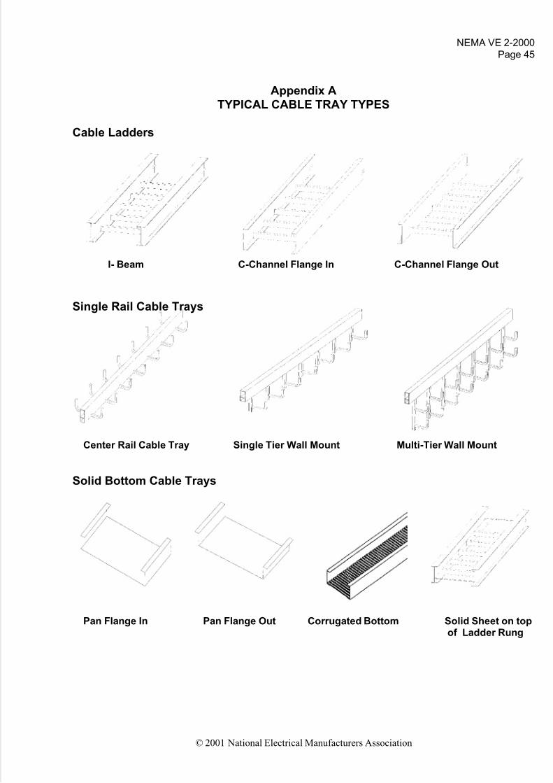
Appendix A
TYPICAL CABLE TRAY TYPES
Cable Ladders
I- Beam C-Channel Flange In C-Channel Flange Out
Single Rail Cable Trays
Center Rail Cable Tray Single Tier Wall Mount Multi-Tier Wall Mount
Solid Bottom Cable Trays
Pan Flange In Pan Flange Out Corrugated Bottom Solid Sheet on topof Ladder Rung

5/14/2018 Cable Tray Installation Nema Ve2 - slidepdf.com
http://slidepdf.com/reader/full/cable-tray-installation-nema-ve2 51/51
NEMA VE 2-2000Page 46
© 2001 National Electrical Manufacturers Association
Trough (Ventilated Cable Trays)
Corrugated Bottom with Holes Pan with Louvers Tray with Close Rung Spacing
Wire Mesh Cable Tray Channel Cable Trays
Wire Mesh Ventilated Bottom Solid Bottom