Embed Size (px)
Citation preview

Cable ManagementSystems


BRITMACFLOOR DISTR IBUTION
GROSVENORFAST F IT FLOOR BOX
BRITONRAISED ACCESS FLOOR BOX
ACCESSORIESFLOOR BOX ACCESSORIES
BRITWAYUNDERFLOOR POWERTRACK
CF TRUNKINGCAVITY FLOOR TRUNKING
BA TRUNKINGBURIED SCREED TRUNKING
BFC TRUNKINGFLUSH SCREED TRUNKING
WINDSOR TRUNKINGALUMINIUM TRUNKING
WINDSOR POWERPOLEALUMINIUM POWERPOLE
MALVERNSTEEL SKIRT ING TRUNKING
CHILTERNSTEEL DADO TRUNKING
WARWICKPVC / BUSBAR TRUNKING
BRITWAYL IGHTING TRACK
BRITACCESSFLOOR GROMMET
DESK MODULESTEEL ENCLOSEDDESK MODULE
TECHNICAL DATA
NUMERIC INDEX
Every Britmac product isrigorously tested beforebeing dispatched to thecustomer. This excellenceis reinforced by thecompany’s registrationof compliance with
ISO 9002: 1994 whichensures that these procedures are
maintained at the highest level.
Britmac’s product ranges are developedwith flexibility in mind, and with theevolution of more modular ranges,customers can be confident of obtainingthe right product for each application.
The same attention to detail can beseen in the company‘s commitment tocustomer service.
With up-to-the minute technology at theheart of its management informationsystems, the company is able tomanufacture and despatch in the shortestpossible time, whilst a communicationsnetwork in it’s Central Sales Office ensuresthat customer enquiries are dealt withspeedily and effectively.
The company’s commitment does not endthere. Specifying Britmac products ensuresnot only a first class product, but also thebenefit of a wide range of support services.For example, comprehensive product andtechnical literature, a highly qualified salesforce and extensive wholesaler training.Britmac‘s Technical Services Department isable to offer expert advice on technicalissues, and the preparation of individualquotes.
2
4
5
6
8
10
12
14
16
28
30
34
38
48
50
52
54
69

2
A pre-wired floor box tested in-house ensures thehighest quality and continuity of finished product aswell as saving time and money during site installation.
The lid hinge designensures that the lid willalways self close.A simple snap-out facilityenables the lid to beremoved for easy accessto the accessory plates.

BR
ITM
AC
FL
OO
RD
IST
RIB
UT
ION
SY
ST
EM
S
3
FLOOR BOX DISTRIBUTIONThe Britmac range of cable managementproducts have been utilised in the design andinstallation of electrical systems in commercialand industrial projects for many years.A policy of continuous development ensures thatour products are of the very highest quality, andare renowned for economy of installation andease of use. The comprehensive Grosvenor Fast-fit and Briton ranges of access floor boxes reflectthis policy and provide a wide choice from whichto select the most appropriate for a specificapplication.Although each range offers its own particularbenefits, many desirable features are maintainedthroughout, which allows a compatible installedappearance to be achieved.Both Grosvenor and Briton units can be suppliedfitted with accessories, pre-wired to customers’requirements and fully factory tested prior todelivery.The products are designed and manufactured atElectrium factories in Brownhills and are supported by a nationwide team of SalesEngineers and Stockists.
An extensive range of accessories covering power,voice and data allows each floorbox to be designedto meet a client’s specific requirements.
Power accessories can be pre-wired to the Britwaybusbar tap-off and factory tested prior to deliveryto site. This bespoke service can also extend tovoice and data, even further reducing installationtime on site.
Options available on overall floor box depth, basebox depth and accessory plate/lid depth (Britononly).
Floorboxes are individually packed for ease ofhandling and stocking. Accessory plates aresupplied separately to meet customers’requirements.
Turn-round lid with snap-out feature enables lidopening to be left to the end user.
High quality mouldings reinforced with steelcomponents provide maximum strength.
The recessed lid caters for a wide range of carpetthicknesses, while the substantial steel plate withinthe lid easily withstands the working loads of theMOB PF2 PS/SPU March 1992 specification forraised floors.
Lower boxes separable integral with accessories toassist in repositioning after wiring.
Enables compliance with BS 7671, 2001(formerly the IEE Wiring Regulations).
Large capacity cablerouting guides ensure cables exit the box safelyand neatly.
Grosvenor four compartmentfloor box fitted with power, voiceand data accessories.

GR
OS
VE
NO
RFA
ST
FIT
RA
ISE
D A
CC
ES
S F
LO
OR
BO
XE
S
4
GR02BL
GR03G
GR04G
GR01G G1AP G1BP
GROSVENOR ‘FAST-FIT’RAISED ACCESS FLOOR BOXES
l
The extensive Grosvenor range covers applications from floor service access traps through to fully equipped 4 compartment floor boxes.
Designed for installation from above the floor panel, all of the access floor boxes in the Grosvenor Fast-Fit range incorporate twin securing clampmechanisms to simplify installation and reduce on-site costs. The securing clamps are extremely simple to operate and adjust to suit a range of floor panel and compressed carpet heights from 20 to 50mm.
1 to 4 compartment versions achievable with only 2 box sizes. Where carpeting is carried out after box installation,
carpet cutting guides are available. 1 & 2 compartment – List No. CG12. 3 & 4 compartment – List No. CG34.
Standard 87mm depth across range provides a generous accessory plate tolid height.
Available with a choice of carpet trim colours. 6 mm lid access for carpet /other floor finish.
1 COMPARTMENT FRAME & LIDS
TRIM COLOUR LIST No
Grey GR01G
Brown GR01BR
Black GR01BL
Suitable for use as a dedicated access trap to in-cavity services by utilising 2 access plates creating a shaped aperture. Order separately if required.
Check availability when ordering
Access plate with semi-circle cut-out G1AP
Blank plate for on-site piercing G1BP
Alternatively, a 1 compartment lower box, occupying half of the frame width,can be added to accommodate any one 66mm wide accessory while stillallowing access to the floor void for other services.
1 compartment lower box G1LB
2 COMPARTMENT FLOOR BOXES
TRIM COLOUR LIST No
Grey GR02G
Brown GR02BR
Black GR02BL
Accepts two 66mm accessories, one of which may be a 13A socket outlet. Any combination of voice and data accessories can be used. Check availability when ordering
3 COMPARTMENT FLOOR BOXES
TRIM COLOUR LIST No
Grey GR03G
Brown GR03BR
Black GR03BL
The most popular size of raised access floor box for use in commercial office applications where power, voice and data services are required.
Utilises 87mm wide accessory plates.
4 COMPARTMENT FLOOR BOXES
TRIM COLOUR LIST No
Grey GR04G
Brown GR04BR
Black GR04BL
Compact 4 compartment unit - utilises 66mm wide accessories. 4 compartment units can provide an attractive and economical solution for
applications, where power, voice and data systems are to be accessed,particularly where both clean and utility power outlets are required or where more than one type of data system is required.
Dimensions & Specifications – see pages 55/56

BR
ITO
NR
AIS
ED
AC
CE
SS
FL
OO
R B
OX
ES
5
BRS3BR
BRS4G
194227
214(cut out)
179.5(cut out)
34 87
300(cut out)
8734
227314
214(cut out)
GROSVENOR ‘FAST FIT’ RAISED ACCESSFLOOR BOXES
GR03 – 3 compartmentGR04 – 4 compartment
GR01 – 1 compartmentGR02 – 2 compartment
305(cut out)
7527
227314
215(cut out)
BRITON RAISED ACCESSFLOOR BOXES
All dimensions in mm Tolerance on cut-out dimensions is ±1mm
BRS3 – 3 compartmentBRS4 – 4 compartment
BRITON RAISED ACCESS FLOOR BOXESl
3 COMPARTMENT
The design of the Briton 3 compartment access floor box is suitable for the majority of standard applications.
The 87mm wide accessory plates allow a popular range of panel mountedaccessories to be fitted as well as standard surface mounted mouldedaccessories
Standard units are a compact 75mm deep, however, boxes having increasedaccessory headroom and/or variations in lower box depth can be readilysupplied ‘tailored’ to suit particular requirements.
Suitable for all raised access floors, units can, in most cases, be installedentirely from above the floor panel. However, a secondary fixing arrangementallows fastening to the underside of the floor panel, for example, wherepre-finished floor panels are specified.
Available with a choice of carpet trim colours. Where carpeting is carried out after box installation, a carpet cutting guide is
available. 3 & 4 compartment – List No.BRFFT. 6mm Lid access for carpet /Other floor finish
3 COMPARTMENT FLOOR BOXES
TRIM COLOUR LIST No
Grey BRS3G
Brown BRS3BR
Black BRS3BL
3 COMPARTMENT ‘SHALLOW’ FLOOR BOX
TRIM COLOUR LIST No
Grey 65mm deep BRS3G/65
Brown 65mm deep BRS3BR/65
Black 65mm deep BRS3BL/65
4 COMPARTMENT FLOOR BOXES
TRIM COLOUR LIST No
Grey BRS4G
Brown BRS4BR
Black BRS4BL
The design of the Briton 4 compartment access floor box offers a high degree of versatility.
The 66mm wide accessory plates allow an extensive range of panel mounted accessories to be fitted.
4 COMPARTMENT ‘SHALLOW’ FLOOR BOX
TRIM COLOUR LIST No
Grey 65mm deep BRS4G/65
Brown 65mm deep BRS4BR/65
Black 65mm deep BRS4BL/65
Dimensions & Specifications – see pages 55/56

SWITCHED 13A SOCKETSl
LIST No
13A 2 Gang switched socket (Crabtree) GB3SS2/BG
13A 2 Gang switched socket (Britmac) GB3SS2BM/BG
13A 2 Gang switched socket CLEAN EARTH GB3SS2CE/BG
13A 2 Gang switched socket Reg. 607 (Crabtree) GB3SS2/607/BG
13A 2 Gang switched socket Reg. 607 (Britmac) GB3SS2BM/607/BG
13A 2 Gang switched socket NON-STD GB3SSN2/BG
13A 2 Gang switched socket NON-STD CLEAN EARTH GB3SSN2CE/BG
13A 2 Gang switched socket NON-STD Reg. 607 GB3SSN2/607/BG
13A 2 Gang switched safety socket 30mA GB3SRCD30/BG
DATA AND COMMUNICATIONSl
LIST No
Accessory plate 4 knockout LJU6C/RJ45 GB3J6C/BG
Accessory plate to accept 6* LJU6C/RJ45 GB3J6C/6BG
Accessory plate to accept 2x 1G standard accessory GB3J3/BG
Accessory plate to accept 2G standard accessory GB32G/BG
Blank plate GB3BP/BG
Accessory plate to accept 4x Alpha GB3ALPHA/BG
Accessory plate to accept 2x Euro module GB3EURO/BG
Accessory plate angled ‘Z’ 4* LJU6C/RJ45 GB3J6CANG/BG
Accessory plate to accept 2x insulated BNC sockets GB3BNC/BG
Accessory plate for 2x 25 pin D sockets GB325D/BG
Accessory plate to accept 2x IBM connectors GB3LAN2/BG
Accessory plate fitted 2x Master telephone sockets GB3ATMM/BG
Shallow plate to accept 1x IBM connector GB3TLAN1/BG
Shallow plate to accept 2x IBM connectors GB3TLAN2/BG
Shallow plate to accept 2x 25 pin D sockets GB3T25D/BG
Shallow plate to accept 2x insulated BNC sockets GB3TBNC/BG All plates 87mm x 173mm. All accessory plates are supplied with fixing screws.
GR
OS
VE
NO
R &
BR
ITO
NA
CC
ES
SO
RIE
S 3
CO
MPA
RT
ME
NT
6
GB3SS2/BG GB3SSN2/BG GB3SS2/607/BG
GB3SRCD30/BG GB3SN2/BG Dual Earth version
GB3S3/BG GB3SN3/BG Clean Earth version
GB3J6C/6BG GB32G/BG GB3J3/BG
GB3ALPHA/BG GB3EURO/BG GB3J6CANG/BG
UNSWITCHED 13A SOCKETSl
LIST No
13A 2 Gang unswitched socket (Crabtree) GB3S2/BG
13A 2 Gang unswitched socket (Britmac) GB3S2BM/BG
13A 2 Gang unswitched socket CLEAN EARTH GB3S2CE/BG
13A 2 Gang unswitched socket Reg. 607 GB3S2/607/BG
13A 2 Gang unswitched socket NON-STD GB3SN2/BG
13A 2 Gang unswitched socket NON-STD CLEAN EARTH GB3SN2CE/BG
13A 2 Gang unswitched socket NON-STD Reg. 607 GB3SN2/607/BG 607 has dual earth terminals Clean Earth has a normal and an isolated earth.
3 SINGLE UNSWITCHED SOCKETSl
LIST No
13A 3 single unswitched sockets GB3S3/BG
13A 3 single unswitched sockets CLEAN EARTH GB3S3CE/BG
13A 3 single unswitched sockets Reg. 607 GB3S3/607/BG
13A 3 single unswitched sockets NON-STD GB3SN3/BG
13A 3 single unswitched sockets NON-STD CLEAN EARTH GB3SN3CE/BG
13A 3 single unswitched sockets NON-STD Reg. 607 GB3SN3/607/BG Power sockets supplied with rear entry terminals as standard.
Side entry terminals on request 607 has dual earth terminals. Clean earth has a normal and an isolated earth.

GR
OS
VE
NO
R &
BR
ITO
NA
CC
ESSOR
IES 1, 2
& 4
CO
MPA
RTM
ENT
7
KNOCKOUT DIMENSIONSl
LJU6C/RJ45 EURO ALPHA BNC
SWITCHED 13A SOCKETSl
LIST No
13A 2 Gang switched socket GBSS2/BG
13A 2 Gang switched socket CLEAN EARTH GBSS2CE/BG
13A 2 Gang switched socket Reg. 607 GBSS2/607/BG
13A 2 Gang switched socket NON-STD GBSSN2/BG
13A 2 Gang switched socket NON-STD CLEAN EARTH GBSSN2CE/BG
13A 2 Gang switched socket NON-STD Reg. 607 GBSSN2/607/BG
GBBNC/BG GBLAN1/BG
GBSS2/BG Clean Earth version
GBS2/BG GBSSN2/BG
GBJ6C/BG GBATMM/BG
GBBP/BG GB25D/BG
UNSWITCHED 13A SOCKETSl
LIST No
13A 2 Gang unswitched socket GBS2/BG
13A 2 Gang unswitched socket CLEAN EARTH GBS2CE/BG
13A 2 Gang unswitched socket Reg. 607 GBS2/607/BG
13A 2 Gang unswitched socket NON-STD GBSN2/BG
13A 2 Gang unswitched socket NON-STD CLEAN EARTH GBSN2CE/BG
13A 2 Gang unswitched socket NON-STD Reg. 607 GBSN2/607/BG Power sockets supplied with rear entry terminals as standard.
Side entry terminals on request When fitting three or more twin sockets within a four compartment regular
floor box, off-set sockets will be required. 607 sockets have dual earth system. Clean earth have a normal and an isolated earth.
22.2
36.6
50
50
47.6
23.7
8.8
9.7
DATA AND COMMUNICATIONSl
LIST No
Plate to accept 4 LJU6C voice or 4 RJ45 data outlets GBJ6C/BG
Plate fitted with master telephone outlets GBATMM/BG
Plate to accept 2 25 pin D sockets GB25D/BG
Plate to accept 2 insulated BNC sockets GBBNC/BG
Blank plate for on-site piercing GBBP/BG
Plate to accept 1 number IBM connector(must be fitted in the outer compatments) GBLAN1/BG
Plate to accept 4x Alpha GBALPHA/BG
Plate to accept 2x Euro modules GBEURO/BG All plates 66mm x 173mm. All accessory plates are supplied with fixing screws.
13A accessory plates are supplied with the appropriate interior fitted.In addition to the most common accessory plates shown, a wide range to suitcontinental and NEMA standards, and for many types of data systems are alsoavailable. Full details available on request.

BR
ITW
AY
UN
DE
RF
LO
OR
PO
WE
R T
RA
CK
8
UNDERFLOOR POWER TRACKl
The Britway underfloor power track system consists of a series of fullyenclosed single phase busbar module units and is designed to beassembled direct onto the floor slab of a cavity floor installation. The units are available in a selection of standard lengths, all compatible with standard floor module and cavity floor trunking sizes.Each length has a facility at regular intervals to accept a pre-wired tapoff unit for connection to either a remote mounted floor access boxor direct to a work station. To complete the product range, the powertrack units are complemented by a minimum of basic components, an incoming cable feeder unit, a track interconnector for joininglengths of track together and a stop end to complete the track run.
POWER TRACK MODULESl
The power track module is a 63A 3 wire single phase busbar unit withthe facility to accept a tap off unit at intervals of 300mm, these allowthe removal or addition of tap off units without the need to isolatethe complete system. The socket comprises a fully shuttered entry,protected when out of use by a dust cover with a retaining cord.The tap off units are retained by an automatic built-in dual operatedlocking device which prevents accidental removal.A purpose designed and built 63A 4 wire clean/high integrity earthsingle phase busbar unit is also available. This is colour coded and hasa non- interchangeable pin configuration to ensure accidental mixingof services does not occur.
POWER TRACK FOR THE SUPPLY OFEQUIPMENT WITH HIGH EARTH LEAKAGECURRENTS (SECTION 607 BS7671)
l
Britway Powertrack has been designed to comply with BS 7671- section 607. Please contact Technical Services for further information.
Both Grosvenor and Briton units can be supplied fitted withaccessories, pre-wired to customers’ requirements and fully factorytested prior to delivery.
TAP OFF PLUGSl
The standard tap off unit comprises a 32A unfused plug fitted with3m of 4mm2 lsf cable in a 16mm flexible metal conduit. Where lengthslonger than 3m are required, a 13A fused tap off unit is fitted andwired with the appropriate length of 2.5mm2 lsf cable.The 16mm flexible metal conduit is terminated with a 20mm adaptorto suit the more readily available and accepted knockout size.Special attention has been paid to the fitting of the flexible conduit tothe plug and to the cable gland, additional unique locking devices arefitted to ensure the conduit cannot work loose to expose the cablesor to interfere with the earth continuity.
Regular socket outletsevery 300mm
Standard 3 bar system
Automatic dual built-inlocking devices
Conduitlocking device
Clean Earth 4 bar system

POWER TRACK MODULESl
TRACK LENGTH STANDARD CLEAN / HIGH INTEGRITY EARTH1200mm BPT12 BPT12TE1800mm BPT18 BPT18TE2400mm BPT24 BPT24TE3600mm BPT36 BPT36TE Tap off sockets at 300mm intervals complete with dust cover and retaining cord. Track fixing plates not included. Powertrack can be supplied for use as Clean, or High Integrity Earth. Label supplied.
CABLE SUPPLY FEED END / STOP END LEFTl
STANDARD CLEAN/HIGH INTEGRITY EARTHFeed Unit BPF1S BPF1STEStop End BPS2S BPS2S
CABLE SUPPLY FEED END / STOP END RIGHTl
STANDARD CLEAN/HIGH INTEGRITY EARTHFeed Unit BPF2S BPF2STEStop End BPS1S BPS1S The cable supply feed end allows the termination of the incoming flexible
cables. The generously sized terminals accept up to 16mm2 cables. Where more than one set of track modules is to be interconnected, cable
supply feed ends may be fitted at both ends. The track stop end is used to complete the track run at the end where no
cable termination is required. Supplied complete with fixing plate.
BR
ITW
AY
UN
DE
RF
LO
OR
PO
WE
R T
RA
CK
9
TRACK FIXING PLATEl
Track fixing plate BPTFS Fit at maximum 1200mm centres.
FLEXIBLE CORNER UNITl
Standard system BPJFClean Earth /High Integrity Earth BPJFTE The flexible corner unit is used for angled bends or to pass around or over an
obstruction. The unit comprises a 1 metre length of 25mm flexible metal conduit and the appropriate 10mm2 LSF cable.
To complete, the unit requires two of the appropriate cable supply feed ends.
32A TAP OFF UNITl
STANDARD CLEAN EARTH HIGH INTEGRITY EARTH 3.0m Unfused BPP3 BPP3TE BPP3TE/6075.0m 13A Fused BPP5F BPP5FTE BPP5FTE/607 3.0m unfused tap off wired to 4mm2 LSF cable housed in a 16mm diameter
flexible metal conduit. Tap off units supplied longer than 3.0m incorporate a 13A fuse and are wired with
2.5mm2 LSF cable, with the exception of High Integrity Earth which has 4mm2. All cable used is LSF type.
BPT24
BPCSTE
BPF1S Cover removed BPF2STE
BPS1S BPS2S
BPTFS
BPJF
BPP3TE
Dimensions & Specifications – see page 57
TRACK INTERCONNECTORl
Supplied complete with fixing plateStandard system BPCSClean Earth /High Integrity Earth BPCSTE Track connector allows the joining together of track modules.

IN-CAVITY FLOOR TRUNKING – TYPE CFl
This trunking is produced in a variety of configurations andin conjunction with raised floor boxes provides a structureddistribution solution for power, voice and data wiring.Manufactured from galvanised steel sheet, the trunking isavailable in a variety of lengths allowing a modularapproach to design and installation. When specified withthe Grosvenor or Briton range of floor boxes pre-assembledwith flexible conduits, installation is reduced to a minimum.
WIDTH1 compartment - 100mm2 compartment - 200mm3 compartment - 300mm
A full range of junction units, bends, tap-off units,risers, end caps, etc, complete the installation.Custom designed and manufactured items areavailable to suit special site conditions.
Raised access floor supplied by System Floors Ltd.
BR
ITM
AC
IN-
CA
VIT
Y F
LO
OR
TR
UN
KIN
G -
TY
PE
CF
10

BR
ITM
AC
IN-
CA
VIT
Y F
LO
OR
TR
UN
KIN
G - T
YP
E C
F
11
CF3T40-600
CF3TU40
CF3JR40
CF3EC40
SYSTEM ANCILLARIESl
End cap CF1EC40
End cap CF2EC40
End cap CF3EC40
Trunking stand off bracket (optional) CFSB
In addition to standard items shown bespoke products can be supplied to meet special site conditions.
CF3JT40
JUNCTION UNITSl
One compartment Tee CF1JT40
Two compartment Tee CF2JT40
Three compartment Tee CF3JT40
Supplied with flyover assembly for cable routing and segregation purposes,and complete with couplers, etc for installation.
One compartment Crossover CF1JX40
Two compartment Crossover CF2JX40
Three compartment Crossover CF3JX40
Supplied with flyover assembly for cable routing and segregation purposes,and complete with couplers, etc for installation.
Dimensions & Specifications – see page 58
TAP-OFF UNITl
One compartment CF1TU40
Two compartment CF2TU40
Three compartment CF3TU40
All tap-off units are trunking width x 300mm long and provide 20mm and25mm diameter knockouts for fitting floorbox flexibles.
Shallow depth of tap-off unit suitable for limited floor void depths. Maintains full cable capacity of trunking.
ANGLE BENDSl
Right angle CF1JR40
Right angle CF2JR40
Right angle CF3JR40
Riser bend CF1RB40
Riser bend CF2RB40
Riser bend CF3RB40
These units have full segregation, as required, and are complete withcouplers,etc for ease of connection.
TRUNKINGl
LENGTH (mm) LIST NO.
One compartment 600 CF1T40 – 600
One compartment 850 CF1T40 – 850
One compartment 1200 CF1T40 – 1200
One compartment 1800 CF1T40 – 1800
Two compartment 600 CF2T40 – 600
Two compartment 800 CF2T40 – 800
Two compartment 1200 CF2T40 – 1200
Two compartment 1800 CF2T40 – 1800
Three compartment 600 CF3T40 – 600
Three compartment 750 CF3T40 – 750
Three compartment 1200 CF3T40 – 1200
Three compartment 1800 CF3T40 – 1800
Constructed throughout from pre-galvanised sheet steel and supplied in thelengths listed.
Supplied fully assembled with lids, couplers, earth straps, etc, for ease ofconnection.
BR
ITM
AC
BU
RIE
D S
CR
EE
D T
RU
NK
ING
- T
YP
E B
A
12
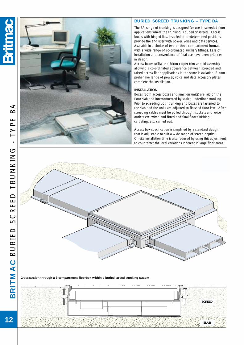
BURIED SCREED TRUNKING – TYPE BAl
The BA range of trunking is designed for use in screeded floorapplications where the trunking is buried ‘inscreed’. Accessboxes with hinged lids, installed at predetermined positionsprovide the end user with power, voice and data services.Available in a choice of two or three compartment formatswith a wide range of co-ordinated auxiliary fittings. Ease ofinstallation and convenience of final use have been prioritiesin design.Access boxes utilise the Briton carpet trim and lid assemblyallowing a co-ordinated appearance between screeded andraised access floor applications in the same installation. A com-prehensive range of power, voice and data accessory platescomplete the installation.
INSTALLATIONBoxes (Both access boxes and junction units) are laid on thefloor slab and interconnected by sealed underfloor trunking.Prior to screeding both trunking and boxes are fastened tothe slab and the units are adjusted to finished floor level. Afterscreeding cables must be pulled through, sockets and voiceoutlets etc. wired and fitted and final floor finishing,carpeting, etc. carried out.
Access box specification is simplified by a standard designthat is adjustable to suit a wide range of screed depths.On-site installation time is also reduced by using this adjustmentto counteract the level variations inherent in large floor areas.
QQQQQQQQQQQQ
¢¢¢¢¢¢¢¢¢¢¢¢
QQQQQQQQQ
¢¢¢¢¢¢¢¢¢
yyyyyyyyyyyyyyyyyyyyyyyyyyyyyyyyyyyyyyyyyyyyyyyyyyyyyyyyyyyyyyyyyyy
Cross section through a 3 compartment floorbox within a buried screed trunking system
SCREED
SLAB

BR
ITM
AC
BU
RIE
D S
CR
EE
D F
LO
OR
TR
UN
KIN
G - T
YP
E B
A
13
BA3T38
BA3UJ38
BA3RB38
BA3EC38
BA3FS38
BA3AE38BL
BA3ASG
FLOORBOX WITH PLAIN SIDES FOR CONDUIT APPLICATIONS
3 Grey BA3ASG
3 Brown BA3ASBR
3 Black BA3ASBL
All floor boxes utilise the Briton range of carpet trim and accessory platesshown on page 6.
G – GREY carpet trim, BR – BROWN carpet trim, BL – BLACK carpet trim. Floor boxes for use with 2 compartment trunking have accessories fitted in
outer compartments with a blank plate fitted to centre compartment.
BURIED SCREED FLOOR BOXESl
THROUGH TYPE
COMPARTMENTS TRIM COLOUR 25mm DEEP 38mm DEEP
2 Grey BA2AT25G BA2AT38G
3 BA3AT25G BA3AT38G
2 Brown BA2AT25BR BA2AT38BR
3 BA3AT25BR BA3AT38BR
2 Black BA2AT25BL BA2AT38BL
3 BA3AT25BL BA3AT38BL
BLANK ONE END
2 Grey BA2AE25G BA2AE38G
3 BA3AE25G BA3AE38G
2 Brown BA2AE25BR BA2AE38BR
3 BA3AE25BR BA3AE38BR
2 Black BA2AE25BL BA2AE38BL
3 BA3AE25BL BA3AE38BL
SYSTEM ANCILLARIESl
DEPTH
COMPARTMENTS DESCRIPTION 25mm 38mm
2 Riser bend BA2RB25 BA2RB38
3 Riser bend BA3RB25 BA3RB38
2 End cap BA2EC25 BA2EC38
3 End cap BA3EC25 BA3EC38
2 Joining strap (spare) BA2FS25 BA2FS38
3 Joining strap (spare) BA3FS25 BA3FS38
One joining strap supplied with each length of trunking. Fixing screws supplied with end cap.
TRUNKINGl
DEPTH
COMPARTMENTS WIDTH LENGTH 25mm 38mm(mm) (mm)
2 150 2000 BA2T25 BA2T38
3 225 2000 BA3T25 BA3T38
One joining strap supplied with each length of trunking. Alternative sizes of trunking can be manufactured to special order.
JUNCTION UNITS - UNIVERSALl
DEPTH
COMPARTMENTS DESCRIPTION 25mm 38mm
2 Universal Junction BA2UJ25 BA2UJ38
3 Universal Junction BA3UJ25 BA3UJ38 This is a universal intersection unit and can be used for either Crossover,
Tee, or Through units.
2 Right angle BA2RA25 BA2RA38
3 Right angle BA3RA25 BA3RA38
One joining strap supplied with each length of trunking.
Dimensions & Specifications – see page 59

BR
ITM
AC
FL
US
H S
CR
EE
D T
RU
NK
ING
- T
YP
E B
FC
14
FLUSH SCREED TRUNKING – TYPE BFCl
The BFC range of trunking is designed for use in a screeded floor application. The trunking is installed flush with the finished floor levelproviding a freely accessible wire-way and offering far greater flexibilityof outlet positions than buried trunking systems.
FEATURES Trunking will withstand the static loading prescribed in specification
BS 6399 Part 1-1996. Unique design eliminates the need for a ribbon screed. Full 65mm deep trunking. PVC edge trim cushions lid noise and provides attractive edge detail. Wide range of power, voice and data accessories available. Full design and take-off service from customers’ drawings is offered.
65
32
Plasticedgetrim
11985
Supportingcrossmember
335
Jackingbracket
Distributed load Distributed loadApplied load
Load applied to lid distributed bysupporting crossmember to trunking edges
Adjustment 40 max
119
TRUNKING SYSTEMEach trunking length is supplied with 1 set of couplers

SYSTEM ANCILLARIESl
COMPARTMENTS DESCRIPTION
3 Riser bend BFC3RB
3 End cap BFCEC
3 Trunking jacking bracket BFCJB
All Units come complete with the necessary Jacking Brackets. Jacking Brackets should be used in pairs at every trunking joint and at
maximum spacing 1200mm.
FLUSH SCREED FLOOR BOXESl
Floor boxes are mounted within a 300mm long steel lid section whichsimply replaces a standard lid. Moulded carpet trims (as Briton range)provide an attractive finish to the access boxes.
COMPARTMENTS CARPET TRIM
3 Grey BFT3G
3 Brown BFT3BR
3 Black BFT3BL
Floor box accessory plates fit within the screed floor box.The plates can be selected from those shown on page 6.
JUNCTION UNITSl
COMPARTMENTS DESCRIPTION
3 Tee BFC3JT
3 Crossover BFC3JX
3 Right angle bend BFC3JR
Supplied complete with necessary couplers.
BR
ITM
AC
FL
US
H S
CR
EE
D T
RU
NK
ING
- TY
PE
BF
C
15
yyyyyyyyyyyyyyyyyyyy
yy
yyyyyy
yyyyyy
Up to 40mmAdjustment
Jacking brackets
SCREED
SLAB
BFC3JX
BFC3T-600
New or existing screeded floor installation utilisingflush screed trunking. Unique jacking bracket detail
eliminates need for ribbon screed.
BFC3JR
BFCJB
BFC3RB
Dimensions & Specifications – see page 60
BFT3G
TRUNKINGl
COMPARTMENTS DESCRIPTION
3 265mm length BFC3T-265
3 600mm length BFC3T-600
3 1200mm length BFC3T-1200
3 1800mm length BFC3T-1800
Other trunking lengths available – details on request.TRUNKING BODY1.2mm pre-galvanised steel sheet with extruded plastic edge trims.TRUNKING LIDS3.0mm thick pre-galvanised steel, with screw fastenings and internal supports.

WIN
DS
OR
AL
UM
INIU
M T
RU
NK
ING
16

WIN
DS
OR
AL
UM
INIU
M D
AD
O T
RU
NK
ING
17
The NEW range of Dado and Skirting trunking is a quality extruded aluminium product offering style coupled with functionality.
All FIVE profiles have a flexible method of internalsegregation, which means that any of the trunkingsections can be divided into one, two, three or even four compartments by using the aluminium dividers.
The snap-in front cover is universal for all of the profiles and therefore the accessories have the same fixing method. Because the cover is 80mm wide, sockets can be added later without the necessity of ordering new front cover plates.
A full range of internal/external bends, flat bends, Tee-pieces etc. are available to ensure that all site situations can be accommodated without the loss of quality of appearance on finish.
In addition to the Dado and Skirting range, Britmac have added a Power Pole to the aluminium range, details can be found on page 28 of this catalogue.
FINISHESThe range is available in anodised aluminium finish or epoxy polyester powder coated from a choice of two standard colours (other colours are available to order by quoting a RAL/BS/NCS number). Paint finishes have a 65% gloss level
ANODISED ALUMINIUM WHITE BS00E55 BLACK BS00E53
50
45˚
18
80
2424
160
50
80
2424
125
66
80
2424
100
66
80
2424
160
100 Profile 200 Profile 300 Profile
400 Profile 500 Profile
Metal Trunking
Medium mechanical stresses
-5˚C to +60˚C
Non-Flame propagating
With electrical continuity characteristics(When fitted with Earth bonding straps)
Protected against solid objects to IP4X
Access cover removable with tools
Providing the product is installed in accordance withapplicable wiring regulations, and the earth terminals areused to ensure earth continuity between all metal partsof the system, the trunking complies with IEC 61084.
Black
White
Anodised
66
45˚
34
80
2424
160

DIVIDERl
Natural NWT550Dimensions 45mm x 1000mm
WIN
DS
OR
10
0A
LU
MIN
IUM
TR
UN
KIN
G
18
NWT82/_ _
NWT103/_ _
NWT104/105
NWT120/_ _
NWT550
NWT102/_ _
NWT110/111
EXTERNAL CORNERl
90° corners supplied complete with two body fitting kits,two pairs of joint cover pieces, and an external front cover piece.Finish as body NWT103/_ _
TRUNKING BODYl
Body supplied complete with body fitting kit.Anodised Aluminium finish NWT120/AAWhite paint finish NWT120/WHBlack paint finish NWT120/BKDimensions 160mm x 50mm x 2000mm
INTERNAL CORNERl
90° corners supplied complete with two body fitting kits,two pairs of joint cover pieces.Finish as body NWT102/_ _
FLAT BENDl
90° bends supplied complete with two body fitting kits,two pairs of joint cover pieces, factory mitred front cover pieces.Riser - Finish as body NWT104/_ _Dropper - Finish as body NWT105/_ _
TEE PIECEl
Each unit supplied with two body fitting kits, two pairs of joint cover pieces.Tee Upward - Finish as body NWT110/_ _Tee Downward - Finish as body NWT111/_ _
FRONT COVERl
Anodised Aluminium finish NWT82/AAWhite paint finish NWT82/WHBlack paint finish NWT82/BKDimensions 80mm x 2000mm
Dimensions & Specifications – see page 61

WIN
DS
OR
10
0A
LU
MIN
IUM
TR
UN
KIN
G
19
Comp. Cross Section 45% CapacityNo. Area (mm2) (mm2)
1 1650 742
2 1000 450
3 1000 450
4 2000 900
A 7400 3330
66
A 160
2
1
3
4
Body
Cover
Internal Corner
Divider
Alignment Pins
Joint Cover Piece
Box Holder
Back Box
Earth Link
STOP ENDSl
Left Hand NWT113/_ Right Hand NWT114/_
JOINT COVER PIECEl
(1 pair per joint). Designed to cover joints when on-site cuttingis required. NWT112/_
BOXHOLDERl
Requires 1 unit per single box and 2 units per double box. NWT551
BODY FITTING KITl
Comprises 4 alignment pins, 1 earth terminal, 1 earth link. NWT555
35MM METAL BOXl
Single Box. SB615Double Box. SB625
SPARE EARTH TERMINALSl
(4 terminals per pack). NWT553
ADJUSTABLE MOUNTING BRACKETSl
50 - 75mm. WT00870 - 105mm. WT009100 - 155mm. WT010
To maintain the line of installation, trunking can be built off the perimeter wallswith the use of purpose designed support brackets.This is particularly useful where radiators restrict the positioning of the dadotrunking.
Dimensions & Specifications – see page 61

DIVIDERl
Natural NWT550Dimensions 45mm x 1000mm
WIN
DS
OR
20
0A
LU
MIN
IUM
TR
UN
KIN
G
20
NWT82/_ _
NWT203
NWT204
NWT220/_ _
NWT550
NWT202
NWT210
TRUNKING BODYl
Body supplied complete with body fitting kit.Anodised Aluminium finish NWT220/AAWhite paint finish NWT220/WHBlack paint finish NWT220/BKDimensions 125mm x 50mm x 2000mm
INTERNAL CORNERl
90° corners supplied complete with two body fitting kits,two pairs of joint cover pieces.Finish as body NWT202/_ _
EXTERNAL CORNERl
90° corners supplied complete with two body fitting kits,two pairs of joint cover pieces, and an external front cover piece.Finish as body NWT203/_ _
FLAT BENDl
90° bends supplied complete with two body fitting kits,two pairs of joint cover pieces, factory mitred front cover pieces.Dropper /Riser - Finish as body NWT204/_ _
TEE PIECEl
Each unit supplied with two body fitting kits, two pairs of joint cover pieces.Tee Upward/Downward - Finish as body NWT210/_ _
FRONT COVERl
Anodised Aluminium finish NWT82/AAWhite paint finish NWT82/WHBlack paint finish NWT82/BKDimensions 80mm x 2000mm
Dimensions & Specifications – see page 61

WIN
DS
OR
20
0A
LU
MIN
IUM
TR
UN
KIN
G
21
Comp. Cross Section 45% CapacityNo. Area (mm2) (mm2)
1 1575 708
2 1000 450
3 1000 450
4 1575 708
A 6250 2812
50
A
125
2
1
3
4
Body
Cover
Internal Corner
Divider
Alignment Pins
Joint Cover Piece
Box Holder
Back Box
Earth Link
STOP ENDSl
Left Hand/Right Hand NWT213/_
JOINT COVER PIECEl
(1 pair per joint). Designed to cover joints when on-site cuttingis required. NWT212/_
BOXHOLDERl
Requires 1 unit per single box and 2 units per double box. NWT551
BODY FITTING KITl
Comprises 4 alignment pins, 1 earth terminal, 1 earth link. NWT555
35MM METAL BOXl
Single Box. SB615Double Box. SB625
SPARE EARTH TERMINALSl
(4 terminals per pack). NWT553
ADJUSTABLE MOUNTING BRACKETSl
50 - 75mm. WT00870 - 105mm. WT009100 - 155mm. WT010
To maintain the line of installation, trunking can be built off the perimeter wallswith the use of purpose designed support brackets.This is particularly useful where radiators restrict the positioning of the dadotrunking.
Dimensions & Specifications – see page 61

DIVIDERl
Natural NWT566Dimensions 61mm x 1000mm
WIN
DS
OR
30
0A
LU
MIN
IUM
TR
UN
KIN
G
22
NWT82/_ _
NWT303
NWT304
NWT320/_ _
NWT566
NWT302
NWT310
TRUNKING BODYl
Body supplied complete with body fitting kit.Anodised Aluminium finish NWT320/AAWhite paint finish NWT320/WHBlack paint finish NWT320/BKDimensions 100mm x 66mm x 2000mm
INTERNAL CORNERl
90° corners supplied complete with two body fitting kits,two pairs of joint cover pieces.Finish as body NWT302/_ _
EXTERNAL CORNERl
90° corners supplied complete with two body fitting kits,two pairs of joint cover pieces, and an external front cover piece.Finish as body NWT303/_ _
FLAT BENDl
90° bends supplied complete with two body fitting kits,two pairs of joint cover pieces, factory mitred front cover pieces.Riser /Dropper - Finish as body NWT304/_ _
TEE PIECEl
Each unit supplied with two body fitting kits, two pairs of joint cover pieces.Tee Upward/Downward - Finish as body NWT310/_ _
FRONT COVERl
Anodised Aluminium finish NWT82/AAWhite paint finish NWT82/WHBlack paint finish NWT82/BKDimensions 80mm x 2000mm
Dimensions & Specifications – see page 61

WIN
DS
OR
30
0A
LU
MIN
IUM
TR
UN
KIN
G
23
Comp. Cross Section 45% CapacityNo. Area (mm2) (mm2)
1 1300 585
2 1320 594
3 1320 594
4 1300 585
A 6600 2970
A
66
100
1
2
3
4
Body
Cover
Internal Corner
Divider
Alignment Pins
Joint Cover Piece
Box Holder
Back Box
Earth Link
STOP ENDSl
Left Hand/Right Hand NWT313/_
JOINT COVER PIECEl
(1 pair per joint). Designed to cover joints when on-site cuttingis required. NWT312/_
BOXHOLDERl
Requires 1 unit per single box and 2 units per double box. NWT560
BODY FITTING KITl
Comprises 4 alignment pins, 1 earth terminal, 1 earth link. NWT555
35MM METAL BOXl
Single Box. SB615Double Box. SB625
SPARE EARTH TERMINALSl
(4 terminals per pack). NWT553
ADJUSTABLE MOUNTING BRACKETSl
50 - 75mm. WT00870 - 105mm. WT009100 - 155mm. WT010
To maintain the line of installation, trunking can be built off the perimeter wallswith the use of purpose designed support brackets.This is particularly useful where radiators restrict the positioning of the dadotrunking.
Dimensions & Specifications – see page 61

DIVIDERl
Natural NWT566Dimensions 61mm x 1000mm
FRONT COVERl
Anodised Aluminium finish NWT82/AAWhite paint finish NWT82/WHBlack paint finish NWT82/BKDimensions 80mm x 2000mm
INTERNAL CORNERl
90° corners supplied complete with two body fitting kits,two pairs of joint cover pieces.Finish as body NWT402/_ _
WIN
DS
OR
40
0A
LU
MIN
IUM
TR
UN
KIN
G
24
NWT82/_ _
NWT403
NWT404
NWT420/_ _
NWT566
NWT402
NWT410
TRUNKING BODYl
Body supplied complete with body fitting kit.Anodised Aluminium finish NWT420/AAWhite paint finish NWT420/WHBlack paint finish NWT420/BKDimensions 100mm x 66mm x 2000mm
EXTERNAL CORNERl
90° corners supplied complete with two body fitting kits,two pairs of joint cover pieces, and an external front cover piece.Finish as body NWT403/_ _
FLAT BENDl
90° bends supplied complete with two body fitting kits,two pairs of joint cover pieces, factory mitred front cover pieces.Riser /Dropper - Finish as body NWT404/_ _
Dimensions & Specifications – see page 61
TEE PIECEl
Each unit supplied with two body fitting kits, two pairs of joint cover pieces.Tee Upward/Downward - Finish as body NWT410/_ _

WIN
DS
OR
40
0A
LU
MIN
IUM
TR
UN
KIN
G
25
Comp. Cross Section 45% CapacityNo. Area (mm2) (mm2)
1 3120 1404
2 1320 594
3 1320 594
4 3120 1404
A 10560 4752
66
A 160
1
2
3
4
Body
Cover
Internal Corner
Divider
Alignment Pins
Joint Cover Piece
Box Holder
Back Box
Earth Link
STOP ENDSl
Left Hand/Right Hand NWT413/_
JOINT COVER PIECEl
(1 pair per joint). Designed to cover joints when on-site cuttingis required. NWT412/_
BOXHOLDERl
Requires 1 unit per single box and 2 units per double box. NWT560
BODY FITTING KITl
Comprises 4 alignment pins, 1 earth terminal, 1 earth link. NWT555
35MM METAL BOXl
Single Box. SB615Double Box. SB625
SPARE EARTH TERMINALSl
(4 terminals per pack). NWT553
ADJUSTABLE MOUNTING BRACKETSl
50 - 75mm. WT00870 - 105mm. WT009100 - 155mm. WT010
To maintain the line of installation, trunking can be built off the perimeter wallswith the use of purpose designed support brackets.This is particularly useful where radiators restrict the positioning of the dadotrunking.
Dimensions & Specifications – see page 61

DIVIDERl
Natural NWT566Dimensions 61mm x 1000mm
FRONT COVERl
Anodised Aluminium finish NWT82/AAWhite paint finish NWT82/WHBlack paint finish NWT82/BKDimensions 80mm x 2000mm
WIN
DS
OR
50
0A
LU
MIN
IUM
TR
UN
KIN
G
26
NWT82/_ _
NWT503/_ _
NWT504/505
NWT520/_ _
NWT566
NWT502/_ _
NWT510/511
TRUNKING BODYl
Body supplied complete with body fitting kit.Anodised Aluminium finish NWT520/AAWhite paint finish NWT520/WHBlack paint finish NWT520/BKDimensions 160mm x 66mm x 2000mm
INTERNAL CORNERl
90° corners supplied complete with two body fitting kits,two pairs of joint cover pieces.Finish as body NWT502/_ _
EXTERNAL CORNERl
90° corners supplied complete with two body fitting kits,two pairs of joint cover pieces, and an external front cover piece.Finish as body NWT503/_ _
FLAT BENDl
90° bends supplied complete with two body fitting kits,two pairs of joint cover pieces, factory mitred front cover pieces.Riser - Finish as body NWT504/_ _Dropper - Finish as body NWT505/_ _
TEE PIECEl
Each unit supplied with two body fitting kits, two pairs of joint cover pieces.Tee Upward - Finish as body NWT510/_ _Tee Downward - Finish as body NWT511/_ _
Dimensions & Specifications – see page 61

WIN
DS
OR
50
0A
LU
MIN
IUM
TR
UN
KIN
G
27
Comp. Cross Section 45% CapacityNo. Area (mm2) (mm2)
1 2624 1181
2 1320 594
3 1320 594
4 3120 1404
A 8384 3773
66
A 160
2
1
3
4
Body
Cover
Internal Corner
Divider
Alignment Pins
Joint Cover Piece
Box Holder
Back Box
Earth Link
STOP ENDSl
Left Hand NWT513/_ Right Hand NWT514/_
JOINT COVER PIECEl
(1 pair per joint). Designed to cover joints when on-site cuttingis required. NWT512/_
BOXHOLDERl
Requires 1 unit per single box and 2 units per double box. NWT560
BODY FITTING KITl
Comprises 4 alignment pins, 1 earth terminal, 1 earth link. NWT555
35MM METAL BOXl
Single Box. SB615Double Box. SB625
SPARE EARTH TERMINALSl
(4 terminals per pack). NWT553
ADJUSTABLE MOUNTING BRACKETSl
50 - 75mm. WT00870 - 105mm. WT009100 - 155mm. WT010
To maintain the line of installation, trunking can be built off the perimeter wallswith the use of purpose designed support brackets.This is particularly useful where radiators restrict the positioning of the dadotrunking.
Dimensions & Specifications – see page 61

WIN
DS
OR
PO
WE
R P
OL
E
28
The Windsor Power Pole is constructed from three or fourcompartment aluminium profile. Its smooth outer finish gives it an aesthetically pleasing appearance, ideally suited to the modern office environment. The top of the PowerPole is suitable for fixing to the underside of a concreteceiling slab, or to a trunking run above a false ceiling,selection of the appropriate fixing bracket is all that isrequired. At floor level the Power Pole ‘Is secured by a screw-fixed base plate, ensuring a high level of rigidity andstability. The standard length of 3 metres will accommodatethe majority of ceiling heights, however, for specialisedapplications, lengths of up to 6 metres can be supplied tospecial order. Accessories are fitted in exactly the same wayas those on the dado and skirting systems. The boxholder isinstalled in a vertical plane, single outlets are used to provideany combination of power, data or telephone connections.Twelve or more single, standard U.K. flush mountedaccessory outlets can be fitted vertically.
FINISHES Standard finish on the Power Pole is epoxy powder coatedWhite BSOOE55 with a 65% gloss level. Other colours areavailable on request. Anodised Aluminium is also available as an option.
PRE-WIRED Britmac are particularly adept at factory Pre-wiring electricalsystems to customer requirements. Windsor Power Poles cantherefore be supplied either in standard kit form, or fully pre-wired to customer specification, with any combination ofpower, data or telephone accessories.
66
100
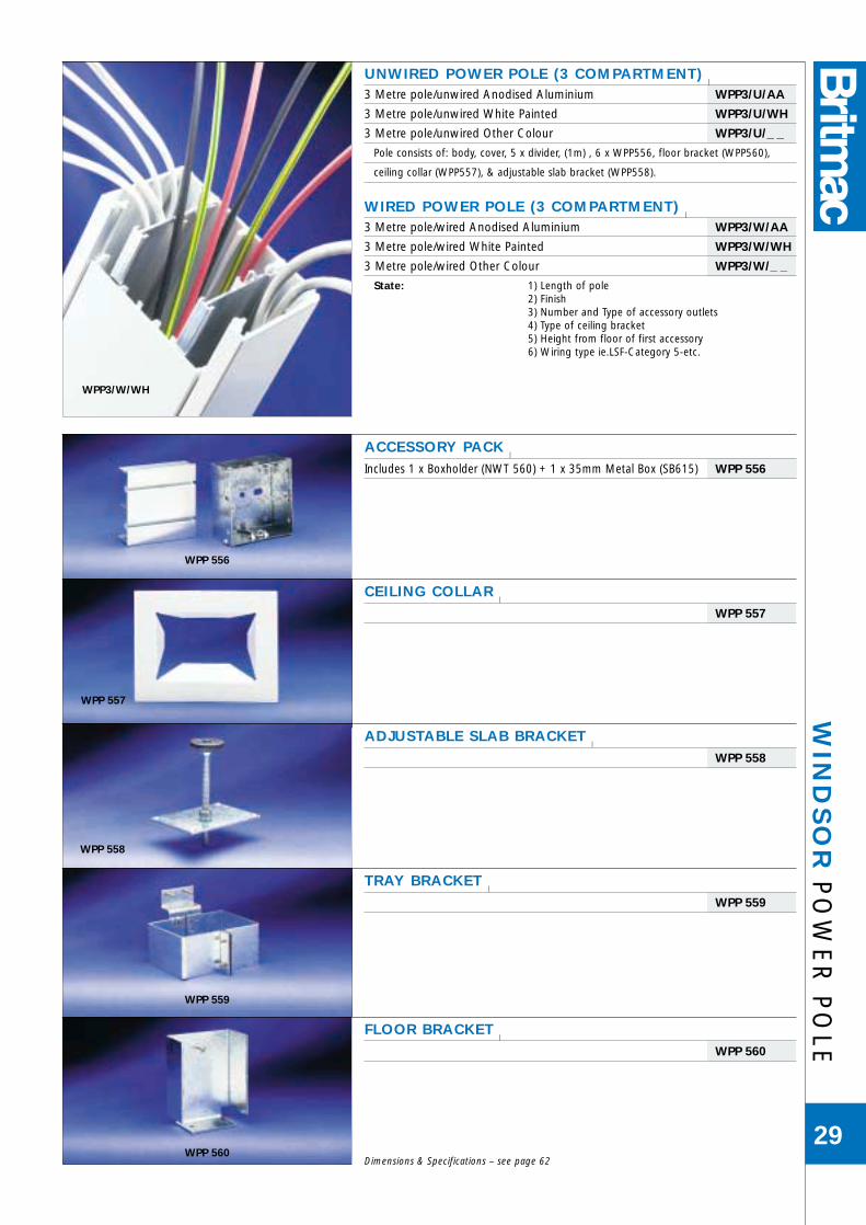
FLOOR BRACKETl
WPP 560
UNWIRED POWER POLE (3 COMPARTMENT)l
3 Metre pole/unwired Anodised Aluminium WPP3/U/AA
3 Metre pole/unwired White Painted WPP3/U/WH
3 Metre pole/unwired Other Colour WPP3/U/_ _
Pole consists of: body, cover, 5 x divider, (1m) , 6 x WPP556, floor bracket (WPP560),
ceiling collar (WPP557), & adjustable slab bracket (WPP558).
WIRED POWER POLE (3 COMPARTMENT)l
3 Metre pole/wired Anodised Aluminium WPP3/W/AA
3 Metre pole/wired White Painted WPP3/W/WH
3 Metre pole/wired Other Colour WPP3/W/_ _
State: 1) Length of pole2) Finish3) Number and Type of accessory outlets4) Type of ceiling bracket5) Height from floor of first accessory6) Wiring type ie.LSF-Category 5-etc.
TRAY BRACKETl
WPP 559
ADJUSTABLE SLAB BRACKETl
WPP 558
CEILING COLLARl
WPP 557
WIN
DS
OR
PO
WE
R P
OL
E
29
WPP3/W/WH
WPP 556
WPP 557
WPP 558
WPP 559
WPP 560
ACCESSORY PACKl
Includes 1 x Boxholder (NWT 560) + 1 x 35mm Metal Box (SB615) WPP 556
Dimensions & Specifications – see page 62

CH
ILT
ER
N D
AD
O T
RU
NK
ING
30
White
Black
Birch Grey

Section
175
47
CH
ILTE
RN
DA
DO
TR
UN
KIN
G
31
CHILTERN DADO TRUNKINGChiltern dado trunking is a range of 3compartment steel trunking and accessoriesdesigned to complement our successful Malvernskirting trunking. Its clean lines and bevellededges particularly appeal to architects,consultants, interior designers and clients alike. A complementary box section feeder trunking isavailable to supply services from above or belowthe installed clado level. The trunking is designedto allow cutting of the lid on site to fit accessoryplates where required, any new edge beingcovered by the neat connector strap provided.Flush fitting accessories from the Diamond rangeenhance the overall appearance of the system.
FEATURES• Bevelled edges allow the trunking to blend in
sympathetically with any decor.
• Steel dividers allow up to 3 services (ie power, voiceand data) to be incorporated within the trunking,providing maximum screening effect for voice/dataservices,
• A full range of internal bends, external bends, tees,feeder sections, etc, are available to ensure that allsite situations can be accommodated without theloss of quality of appearance or finish.
• As an alternative to flush fitting accessories, thecapital range of moulded accessories can be fittedon the trunking.
INSTALLATION NOTES The illustration shows the main components of theChiltern system. Trunking body can be cut to anyrequired length before screw fixing to wall. Adjacentlengths are connected by the use of a jointing kit (5).Lids and accessory plates are fitted as required withnominal gap of 15mm. They are secured by use ofthe connector straps (4) which are 35mm wide andneatly cover any cut ends. Similar overlap provisionis a feature of inside and outside bends.
When 3 compartment trunking is used, powercabling should be run in either top or bottomcompartments. if deep data accessories are to befitted then the centre compartment should beallocated for data cabling, back boxes will then onlybe required for the power and telephone accessories.
ACCESSORY PLATESAre all 235mm long and are all supplied completewith 2 connector straps, 1 back box and 1 earth lead.
COLUMN SETSCan be made up on site with a combination of 2 internal bends and 2 external bends joinedtogether with le of trunking cut on site. Minimum wall dimensions 85mm.
ANGLE BENDS (NON STANDARD) Angled front cover units are available to specialorder and are supplied complete with 2 connectorstraps and 1 earth lead Note: the standard trunkingcan be mitre cut on site.
FINISHThe range is availablewith an epoxy polyesterpowder coat finish froma choice of 3 standardcolours. Paint finisheshave a 65% gloss level.Primer only or any othercolour is available toorder by quoting aRAL/BS/NCS number.
White BS 00ES5
Black BS 00E53
Birch Grey BS 00A05
175
47
=
=
=
1
2
3
4
5
6
2
1 Trunking complete
2 End cap
3 Accessory plate fittedwith 2 gang socketand Accessory backbox
4 Connector strap
5 Jointing Kit
6 Earth lead

SYSTEM ACCESSORIESl
ACCESSORY PLATES
13A 1 gang Unswitched socket CD020/_ _
13A 1 gang Unswitched socket NON-STD CD021/_ _
13A 1 gang Unswitched socket NON-STD, CLEAN EARTH CD022/_ _
13A 1 gang switched socket CD023/_ _
13A 1 gang switched socket NON-STD CD024/_ _
13A 1 gang switched socket NON-STD, CLEAN EARTH CD025/_ _
13A 2 gang Unswitched socket CD026/_ _
13A 2 gang Unswitched socket NON-STD CD027/_ _
13A 2 gang Unswitched socket NON-STD, CLEAN EARTH CD028/_ _
Dimensions: Lid section 235mm
• All plates supplied complete with 2 connector straps, 1 back box and 1 earth lead.
RISER UNITSl
Vertical trunking 1.0m length CD005/_ _
Vertical trunking 2.0m length CD006/_ _
Tee junction interface vertical trunking section CD014/_ _
Crossover junction interface trunking section CD015/_ _
Vertical trunking end cap CD019/_ _
• Vertical trunking 150mm x 40mm, 3 compartment.• Junction unit includes flyover kit.
BENDSl
Internal bend (90°) CD010/_ _
External bend (90°) CD011/_ _
Flat bend – left hand CD016/_ _
Flat bend – right hand CD017/_ _
Flat bend – vertical trunking CD018/_ _
• Internal bend supplied with lid and integral jointing facility.• External bend supplied with lid and 2 joining kits.
END CAPSl
Left and right hand CD012/_ _
• Supplied complete with fixing brackets and screws.
TRUNKING BODY AND LIDl
3 Compartment Trunking, White painted lid CD001/WH
3 Compartment Trunking, Black painted lid CD001/BK
3 Compartment Trunking, Birch Grey painted lid CD001/BG
Dimensions: 180mm x 47mm x 2000mm length
• Body and lid supplied complete with 1 joining kit, 1 connector strap and 1 earth lead.• Body and lid are available separately. Details on request.
CH
ILT
ER
ND
AD
O T
RU
NK
ING
32
CD001/BG
CD011/BK CD012/BG
CD005/BG CD014/BG
CD024/BK
CD027/BG
Suffix List No. _ _/WH (WHITE paint), _ _/BK (BLACK paint), _ _/BG (BIRCH GREY).Other colour finishes available to order.
Dimensions & Specifications – see page 66

SYSTEM ANCILLARIESl
Spare painted connector straps CD004/_ _
Spare vertical trunking connector straps CD007/_ _
• Connector straps and jointing kits supplied as standard in stated quantities with alltrunking body, lid, assembly and accessory plates as appropriate.
Spare galvanised accessory back box SK041/_ _
• Supplied as standard with all accessory plates.
Spare earth lead – 2.5mm2, 200mm length WT047/_ _
• Supplied as standard with all lid sections and accessory plates.
SYSTEM ACCESSORIESl
ACCESSORY PLATES
13A 2 gang Switched socket CD029/_ _
13A 2 gang Switched socket NON-STD CD030/_ _
13A 2 gang Switched socket NON-STD, CLEAN EARTH CD031/_ _
Plate fitted with single secondary voice socket CD040/_ _
Plate fitted with twin secondary voice socket CD041/_ _
Plate fitted with single master voice socket CD042/_ _
Plate fitted with twin master voice socket CD043/_ _
Plate fitted with twin secondary/master voice socket CD044/_ _
Plate blank for customers’ own piercing CD050/_ _
Plate pierced to accept 1 gang standard accessory CD051/_ _
Plate pierced to accept 2 gang standard accessory CD052/_ _
Plate pierced to accept single BNC outlet CD060/_ _
Plate pierced to accept two BNC outlets CD061/_ _
Plate pierced to accept single 25D outlet CD062/_ _
Plate pierced to accept two 25D outlets CD063/_ _
Plate pierced to accept single IBM outlet CD064/_ _
Plate pierced to accept two IBM outlets CD065/_ _
Plate fitted with two knockouts to accept modular RJ45 or CD045/_ _CJU6C voice outlets
• Plates are available to order to suit other data connections.
* Product featured is finished in blue paint colour BS 20C40.
CH
ILTE
RN
DA
DO
TR
UN
KIN
G
33
CD029/WH
CD004/BK CD004/WH CD007/BG
Suffix List No. _ _/WH (WHITE paint), _ _/BK (BLACK paint), _ _/BG (BIRCH GREY).Other colour finishes available to order.
CD030*
CD062/WH
CD052/BK
Dimensions & Specifications – see page 66

MA
LVE
RN
SK
IRT
ING
TR
UN
KIN
G
34
White
Black
Birch Grey
Section
175
47
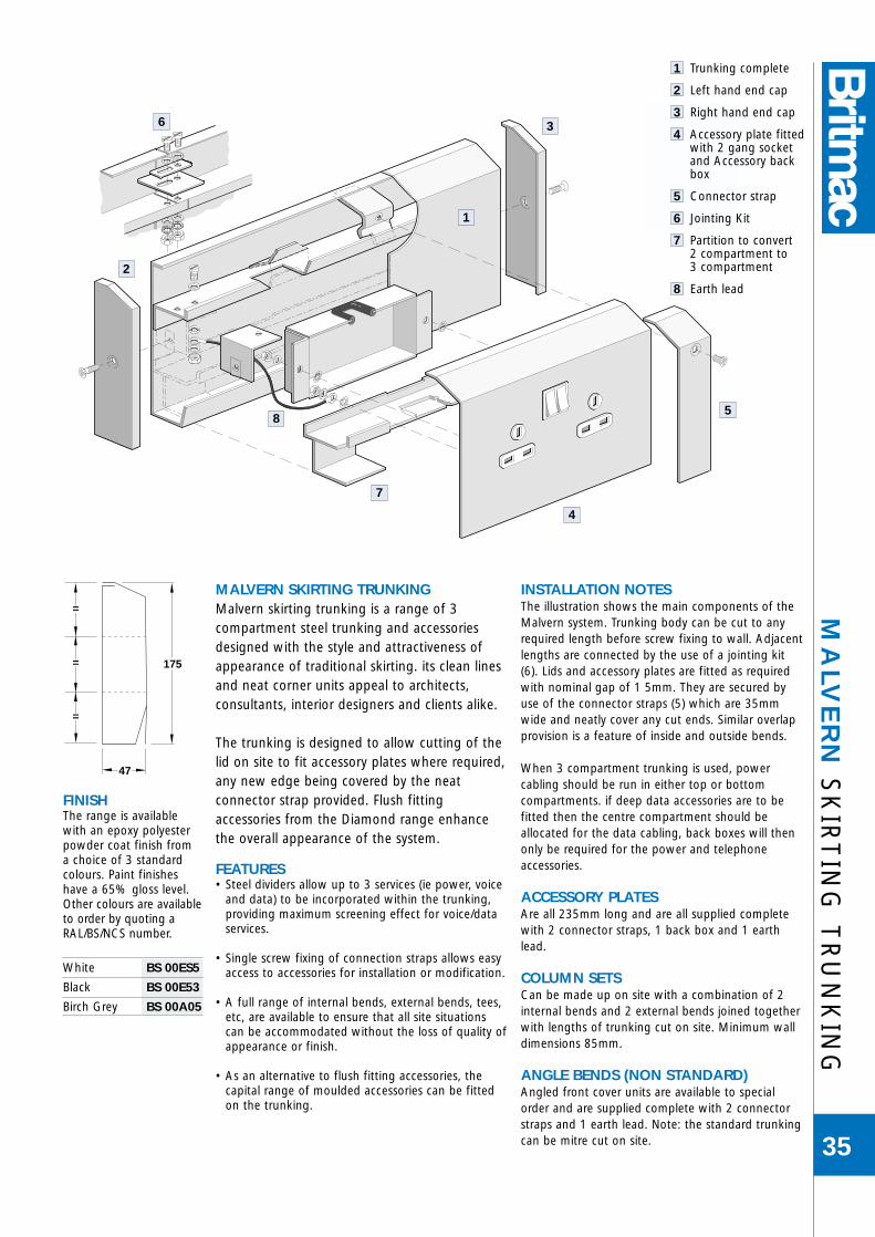
FINISHThe range is availablewith an epoxy polyesterpowder coat finish froma choice of 3 standardcolours. Paint finisheshave a 65% gloss level.Other colours are availableto order by quoting aRAL/BS/NCS number.
White BS 00ES5
Black BS 00E53
Birch Grey BS 00A05
MA
LVE
RN
SK
IRT
ING
TR
UN
KIN
G
35
MALVERN SKIRTING TRUNKINGMalvern skirting trunking is a range of 3compartment steel trunking and accessoriesdesigned with the style and attractiveness ofappearance of traditional skirting. its clean linesand neat corner units appeal to architects,consultants, interior designers and clients alike.
The trunking is designed to allow cutting of thelid on site to fit accessory plates where required,any new edge being covered by the neatconnector strap provided. Flush fittingaccessories from the Diamond range enhancethe overall appearance of the system.
FEATURES• Steel dividers allow up to 3 services (ie power, voice
and data) to be incorporated within the trunking,providing maximum screening effect for voice/dataservices.
• Single screw fixing of connection straps allows easyaccess to accessories for installation or modification.
• A full range of internal bends, external bends, tees,etc, are available to ensure that all site situationscan be accommodated without the loss of quality ofappearance or finish.
• As an alternative to flush fitting accessories, thecapital range of moulded accessories can be fittedon the trunking.
INSTALLATION NOTES The illustration shows the main components of theMalvern system. Trunking body can be cut to anyrequired length before screw fixing to wall. Adjacentlengths are connected by the use of a jointing kit(6). Lids and accessory plates are fitted as requiredwith nominal gap of 1 5mm. They are secured byuse of the connector straps (5) which are 35mmwide and neatly cover any cut ends. Similar overlapprovision is a feature of inside and outside bends.
When 3 compartment trunking is used, powercabling should be run in either top or bottomcompartments. if deep data accessories are to befitted then the centre compartment should beallocated for the data cabling, back boxes will thenonly be required for the power and telephoneaccessories.
ACCESSORY PLATESAre all 235mm long and are all supplied completewith 2 connector straps, 1 back box and 1 earthlead.
COLUMN SETSCan be made up on site with a combination of 2internal bends and 2 external bends joined togetherwith lengths of trunking cut on site. Minimum walldimensions 85mm.
ANGLE BENDS (NON STANDARD) Angled front cover units are available to specialorder and are supplied complete with 2 connectorstraps and 1 earth lead. Note: the standard trunkingcan be mitre cut on site.
4
7
3
1
2
6
85
175
47
=
=
=
1 Trunking complete
2 Left hand end cap
3 Right hand end cap
4 Accessory plate fittedwith 2 gang socketand Accessory backbox
5 Connector strap
6 Jointing Kit
7 Partition to convert 2 compartment to 3 compartment
8 Earth lead

TRUNKING BODY AND LIDl
3 Compartment Trunking, White painted lid SK300/WH
3 Compartment Trunking, Black painted lid SK300/BK
3 Compartment Trunking, Birch Grey painted lid SK300/BG
Dimensions: 175mm x 47mm x 2000mm length
• Body and lid supplied complete with 1 joining kit, 1 connector strap and 1 earth lead.• Lower divider is supplied loose for site fitting.• Lid only painted.• Body and lid are available separately. Details on request.
MA
LVE
RN
SK
IRT
ING
TR
UN
KIN
G
36
SK300/BG
Suffix List No. _ _/WH (WHITE paint), _ _/BK (BLACK paint), _ _/BG (BIRCH GREY).Other colour finishes available to order.
BENDSl
Internal bend SK010/_ _
External bend SK011/_ _
• Internal bend supplied with lid and integral jointing facility.• External bend supplied with lid and 2 jointing kits.
SK010/WH SK011/BK
SK017/BG SK016/WH
SK310/BK
SK322
RISER BENDSl
Bottom entry suitable for use with flush screed trunking Type BFC SK330/_ _
Bottom entry suitable for use with BA 25mm buried screed trunking SK308/_ _
Bottom entry suitable for use with BA 38mm buried screed trunking SK310/_ _
Rear entry suitable for use with BA 25mm buried screed trunking SK322/GV
Rear entry suitable for use with BA 38mm buried screed trunking SK324/GV
Rear entry suitable for use with flush screed trunking Type BFC SK331/GV
• Bottom entry units include 500mm trunking and lid sections, flyovers, 2 connectingstraps, 2 jointing kits and 2 earth leads.
THRESHOLD UNITl
3 compartment door threshold unit SK316/_ _
• Supplied complete with 2 body and lid sections, 1 set of left and right end caps, 2jointing kits, 2 connector straps, 2 earth leads, 1 metere of 3 compartment 38mm buriedscreed trunking and 2 buried screed bends.
• To suit standard doorway width of 1400mm.
• 85mm maximum screed depth.
* Note Screed depth 85mm max.
END CAPSl
Left hand SK017/_ _
Right hand SK016/_ _
• Supplied complete with fixing bracket and screws.
390
1400
390
*
1000
Dimensions & Specifications – see page 66

Spare partition – length 2000mm SK044/GV
SYSTEM ACCESSORIESl
ACCESSORY PLATES
13A 1 gang Switched socket SK025/_ _
13A 2 gang Switched socket SK026/_ _
13A 2 gang Switched socket NON-STD SK056/_ _
13A 2 gang Switched socket NON-STD, CLEAN EARTH SK057/_ _
Plate pierced to accept 1 gang standard accessory SK027/_ _
Plate pierced to accept 2 gang standard accessory SK028/_ _
Plate blank for customers own piercing SK031/_ _
Dimensions: Lid section 235mm
• All plates supplied complete with 2 connector straps, 1 back box and 1 earth lead.
Plate fitted with 1 master voice outlet IDC connection SK052/_ _
Plate fitted with 2 master voice outlet IDC connections SK053/_ _
Plate fitted with two knockouts to accept modular RJ45 or SK029/_ _CJU6C voice outlets
• Plates are available to order to suit other data connections.
SYSTEM ANCILLARIESl
Spare galvanised accessory back box SK041
• Supplied as standard with all accessory plates.
MA
LVE
RN
SK
IRT
ING
TR
UN
KIN
G
37
SK056/WH
SK041
Suffix List No. _ _/WH (WHITE paint), _ _/BK (BLACK paint), _ _/BG (BIRCH GREY).Other colour finishes available to order.
SK053/BG
SK027/BK
SK043 SK042/BG WT047
SK044
Spare painted connector straps SK042/_ _
Spare joining kit SK043/GV
• Connector straps and jointing kits supplied as standard in stated quantities with all trunking body, lid, assembly and accessory plates as appropriate.
Spare earth lead – 2.5mm2, 200mm length WT047
• Supplied as standard with all lid sections and accessory plates.
Dimensions & Specifications – see page 66

WA
RW
ICK
MO
DU
LA
R P
VC
RA
NG
E
38
The WARWICK PVC modular trunking range has beendesigned and manufactured using the expertise from two of the longest established names in British Electricalmanufacturing, Crabtree and Britmac. Crabtree, establishedin 1919 is a leader in Electrical accessories in both the UK.and overseas markets and Britmac, one of the forerunners inCable Management and flat plate accessories, have combinedto develop the new WARWICK range to compliment an
already large electrical installation equipment offering.
Both Crabtree and Britmac are part of Electrium, a major supplier to the electrical installation industry, both have
extensive nationwide distributor coverage and are used on many specification projects.
The new WARWICK range can be mounted at either Dado or Skirting level and can be
purchased as a standard system for hard wiringor with a factory fitted 63Amp bus-bar system
in the centre compartment of the trunking.
• WARWICK accepts standard “Crabtree”wiring accessories
• WARWICK accepts 30mm deepsocket boxes• WARWICK accepts 63Amp 4 Bar
Bus-Bar track• WARWICK accepts a full range of
complimentary fittings (bends,corners etc.)
• WARWICK accepts ample cable capacity
• WARWICK accepts integrationwith other surface products

WARWICK 1l
• Base Unit
• Angled Top and Bottom Covers
• Main Centre Cover
See Page 41
WA
RW
ICK
MO
DU
LA
R P
VC
RA
NG
E
39
50 mm
170
mm
85 m
m42
mm
42 m
m
WARWICK 2l
• Base Unit
• Angled Top Cover
• Main Centre Cover
• Square Bottom Cover
See Page 42
50 mm
170
mm
85 m
m42
mm
42 m
m
WARWICK 3l
• Base Unit
• Square Top and Bottom Covers
• Main Centre Cover
See Page 43
50 mm
170
mm
85 m
m42
mm
42 m
m
WARWICK 4l
• Base Unit
• Base Extension
• Angled Top Cover
• 2 x Main Covers
See Page 44
212
mm
50 mm
85 m
m85
mm
42 m
m
WARWICK 5l
• Base Unit
• Base Extension
• Square Top Cover
• 2 x Main Covers
See Page 45
212
mm
50 mm
85 m
m85
mm
42 m
m

WA
RW
ICK
AN
CIL
LA
RY
IT
EM
S A
ND
SPA
RE
S
40
METAL SCREENINGShould metal screening be required, aluminium sections can be supplied for both top and bottom sections of the trunking to ensure “spiking” does not occur. If screeneddata/telephone cables are being used within the wiring system internal metal screening is not needed.
QUICK GUIDE TO FIVE PVC PROFILES
WARWICK 1 WARWICK 2 WARWICK 3 WARWICK 4 WARWICK 5
Ref No Ref No Ref No Ref No Ref No
Trunking Pack BCL1 BCL2 BCL3 BCL4 BCLS
Internal Bend BCL1/IB BCL2/IB BCL3/IB BCL4/IB BCL5/IB
External Bend BCL1/EB BCL2/EB BCL3/EB BCL4/EB BCL5/EB
Flat Angle (Downward) BCL1/FAD BCL2/FAD BCL3/FAD BCL4/FAD BCL5/FAD
Flat Angle (Upward) – BCL2/FAU – BCL4/FAU BCL5/FAU
Flat Tee (Downward) BCL1/FTD BCL2/FTD BCL3/FTD BCL4/FTD BCL5/FTD
Flat Tee (Upward) – BCL2/FTU – BCL4/FTU BCL5/FTU
Stop End - Left BCL1/SEL BCL2/SEL BCL3/SEL BCL4/SEL BCL5/SEL
Stop End - Right – BCL2/SER – BCL4/SER BCL5/SER
Coupler Pack BCL1/CP BCL2/CP BCL3/CP BCL4/CP BCL5/CP
Angled Cable Retainer BCL/ACR BCL/ACR – BCL/ACR –
Standard Cable Retainer BCL/SCR BCL/SCR BCL/SCR BCL/SCR BCL/SCR
Square Cable Retainer – BCL/SQCR BCL/SQCR BCL/SQCR BCL/SQCR
Single Gang Accessory Box BCL/SGB BCL/SGB BCL/SGB BCL/SGB BCL/SGB
Twin Gang Accessory Box BCL/TGB BCL/TGB BCL/TGB BCL/TGB BCL/TGB
ANGLED SECTION SCREENl
Supplied in 1m lengths BCL/ASS
SQUARE SECTION SCREENl
Supplied in 1m lengths BCL/SSS
ANGLED COVER SECTIONPack Quantity 5 x 3m BCL/ACS
MAIN COVERPack Quantity 5 x 3m BCL/MC
SQUARE COVER SECTIONPack Quantity 5 x 3m BCL/SCS
BASE EXTENSIONPack Quantity 5 x 3m BCL/BE
FLUSH BACK BOXPack Quantity 1 BCL/FBB
MAIN BASE SECTIONPack Quantity 1 BCL/MB
Dimensions & Specifications – see pages 63-65

TRUNKING PACKl
Pack Quantity 2 x 3m lengths BCL1
Profile assembly includes:
• Base Section
• 2 x Angled Covers
• 1 x Main Cover
Overall Size:
• 170mm x 50mm
WA
RW
ICK
1P
VC
TR
UN
KIN
G
41
50 mm17
0 m
m
85 m
m42
mm
42 m
m
INTERNAL BENDPack Quantity 1 BCL1/IB
EXTERNAL BENDPack Quantity 1 BCL1/EB
FLAT ANGLEPack Quantity 1 BCL1/FAD
FLAT TEEPack Quantity 1 BCL1/FTD
STOP ENDPack Quantity 1 BCL1/SEL
COUPLER PACKPack Quantity 5 BCL1/CP
ANGLED CABLE RETAINERPack Quantity 10 BCL/ACR
SINGLE GANG ACCESSORY BOXPack Quantity 10 BCL/SGB
TWIN GANG ACCESSORY BOXPack Quantity 10 BCL/TGB
Dimensions & Specifications – see pages 63-65

TRUNKING PACKl
Pack Quantity 2 x 3m lengths BCL2
Profile assembly includes:
• Base Section
• 1 x Angled Cover
• 1 x Main Cover
• 1 x Square Cover
Overall Size:
• 170mm x 50mm
WA
RW
ICK
2P
VC
TR
UN
KIN
G
42
50 mm
170
mm
85 m
m42
mm
42 m
m
INTERNAL BENDPack Quantity 1 BCL2/IB
EXTERNAL BENDPack Quantity 1 BCL2/EB
FLAT ANGLE (DOWNWARD)Pack Quantity 1 BCL2/FAD
FLAT ANGLE (UPWARD)Pack Quantity 1 BCL2/FAU
FLAT TEE (UPWARD)Pack Quantity 1 BCL2/FTU
FLAT TEE (DOWNWARD)Pack Quantity 1 BCL2/FTD
STOP END (LEFT)Pack Quantity 1 BCL2/SEL
STOP END (RIGHT)Pack Quantity 1 BCL2/SER
COUPLER PACKPack Quantity 5 BCL2/CP
ANGLEDCABLE RETAINERPack Quantity 10
BCL/ACR
SQUARECABLE RETAINERPack Quantity 10
BCL/SQCRSINGLE GANG ACCESSORY BOXPack Quantity 10 BCL/SGB
TWIN GANG ACCESSORY BOXPack Quantity 10 BCL/TGB
Dimensions & Specifications – see pages 63-65

TRUNKING PACKl
Pack Quantity 2 x 3m lengths BCL3
Profile assembly includes:
• Base Section
• 2 x Square Covers
• 1 x Main Cover
Overall Size:
• 170mm x 50mm
WA
RW
ICK
3P
VC
TR
UN
KIN
G
43
50 mm
170
mm
85 m
m42
mm
42 m
m
INTERNAL BENDPack Quantity 1 BCL3/IB
EXTERNAL BENDPack Quantity 1 BCL3/EB
FLAT ANGLEPack Quantity 1 BCL3/FAD
FLAT TEEPack Quantity 1 BCL3/FTD
STOP ENDPack Quantity 1 BCL3/SEL
COUPLER PACKPack Quantity 5 BCL3/CP
SQUARE CABLE RETAINERPack Quantity 10 BCL3/SEL
SINGLE GANG ACCESSORY BOXPack Quantity 10 BCL/SGB
TWIN GANG ACCESSORY BOXPack Quantity 10 BCL/TGB
Dimensions & Specifications – see pages 63-65

TRUNKING PACKl
Pack Quantity 2 x 3m lengths BCL4
Profile assembly includes:
• Base Section
• 1 x Base Extension
• 1 x Angled Cover
• 2 x Main Covers
Overall Size:
• 212mm x 50mm
WA
RW
ICK
4P
VC
TR
UN
KIN
G
44
212
mm
50 mm
85 m
m85
mm
42 m
m
INTERNAL BENDPack Quantity 1 BCL4/IB
EXTERNAL BENDPack Quantity 1 BCL4/EB
FLAT ANGLE (DOWNWARD)Pack Quantity 1 BCL4/FAD
FLAT ANGLE (UPWARD)Pack Quantity 1 BCL4/FAU
FLAT TEE (DOWNWARD)Pack Quantity 1 BCL4/FTD
FLAT TEE (UPWARD)Pack Quantity 1 BCL4/FTU
STOP END (LEFT)Pack Quantity 1 BCL4/SEL
STOP END (RIGHT)Pack Quantity 1 BCL4/SER
COUPLER PACKPack Quantity 5 BCL4/CP
ANGLED CABLE RETAINERPack Quantity 10 BCL/ACR
SINGLE GANG ACCESSORY BOXPack Quantity 10 BCL/SGB
TWIN GANG ACCESSORY BOXPack Quantity 10 BCL/TGB
Dimensions & Specifications – see pages 63-65

WA
RW
ICK
5P
VC
TR
UN
KIN
G
45
212
mm
50 mm
85 m
m85
mm
42 m
m
INTERNAL BENDPack Quantity 1 BCL5/IB
EXTERNAL BENDPack Quantity 1 BCL5/EB
FLAT ANGLE (DOWNWARD)Pack Quantity 1 BCL5/FAD
FLAT ANGLE (UPWARD)Pack Quantity 1 BCL5/FAU
FLAT TEE (DOWNWARD)Pack Quantity 1 BCL5/FTD
FLAT TEE (UPWARD)Pack Quantity 1 BCL5/FTU
STOP END (LEFT)Pack Quantity 1 BCL5/SEL
STOP END (RIGHT)Pack Quantity 1 BCL5/SER
COUPLER PACKPack Quantity 5 BCL5/CP
SQUARE CABLE RETAINERPack Quantity 10 BCL/SQCR
SINGLE GANG ACCESSSORY BOXPack Quantity 10 BCL/SGB
TWIN GANG ACCESSORY BOXPack Quantity 10 BCL/TGB
Dimensions & Specifications – see pages 63-65
TRUNKING PACKl
Pack Quantity 2 x 3m lengths BCL5
Profile assembly includes:
• Base Section
• 1 x Base Extension
• 1 x Square Cover
• 2 x Main Covers
Overall Size:
• 212mm x 50mm

WA
RW
ICK
BU
S-B
AR
TR
UN
KIN
G
46
• The Warwick Bus-Bar has been designed to fit into any of the five standard Warwick PVCtrunkings.
• Available with a full range of accessories foreasy installation.
• Single and double plug-in accessory boxeswhich locate into the Bus-Bar track and allowcable termination to standard 13A sockets.
• Safety Bus-Bar cover
• Fully integrated system
• WARWICK standard trunkings can beupgraded to a Bus-Bar system utilising fullrange of separate parts.
• The Bus-Bar has a standard configuration with 4bars - Live, Neutral, Earth and a separate bar fora clean Earth requirement and Regulation 607.The bars are clearly marked on the connectorblocks and the snap-in boxes. A standard 3-barsystem can be achieved if required.
41
5
3
2
Bus-Bar supplied complete in 3m lengths,consisting of Bus-Bar, Bus-Bar cover, PVC mainbody (BCL/MB), and PVC main cover (BCL/MC).We do not recommend Bus-Bar be cut on site.Bus-Bar lengths are supplied separately to allowflexibility on site, and can be ordered in varyinglengths to suit the installation. The Bus-BarAssembly will fit into any Warwick PVC profile.
1 metre length BCL/BB11/2 metre length BCL/BB05
For installations requiring Bus-Bar, we stronglyrecommend the order is handled by the PROJECTSALES TEAM who offer a free installation designservice.
1 Bus-Bar Assembly
2 Bus-Bar Cover
3 Connector Block
4 Corner Assembly
5 Single Gang Accessory Box

WA
RW
ICK
BU
S-B
AR
TR
UN
KIN
G
47
BUS BAR ASSEMBLYPVC Base, Bus-Bar, Busbar Cover & Main Cover BCL/BB3A
BUS BAR ASSEMBLYBus-Bar Assembly 1.0m BCL/BB1Bus-Bar Assembly 0.5m BCL/BB05
BUS-BAR CORNER ASSEMBLYStandard Pack 1 - 400mm Cable Length BCL/BBCA
BUS-BAR END STOP (LEFT)Standard Pack 1 BCL/BBSL
BUS-BAR END STOP (RIGHT)Standard Pack 1 BCL/BBSR
BUS-BAR MAINS CONNECTOR BLOCKPack Quantity 1 BCL/BBMC
BUS-BAR SINGLE GANG ACCESSORY BOXStandard Pack 10 BCL/BBSB
SINGLE GANG DATA/ TELEPHONE BOXStandard Pack 10 BCL/SGB
BUS-BAR COUPLER PACKStandard Pack 5 BCL/BBCB
BUS-BAR TWIN-GANG ACCESSORY BOXStandard Pack 10 BCL/BBTB
TWIN GANG BOXStandard Pack 10 BCL/TGB
Dimensions & Specifications – see pages 63-65

BR
ITW
AY
LIG
HT
ING
& L
OW
PO
WE
R T
RA
CK
48
LIGHTING & LOW POWER TACK – TYPE BLThe comprehensive Britway Track System Type BL offers a choice of 25 or 40 Amp ratings in single phase, twin single phase circuitor three phase configurations. With an overall installed cost(material and labour), equivalent to that for a cabled installation,the considerable benefits of busbar systems are available to theend user without incurring a financial penalty.
The system is extremely easy to install. The track is both strong and lightweight for ease of handling on site. It is available in 3metre lengths with optional 2 metre lengths for make up purposes.They incorporate slide together joints that are designed for rapidassembly and accurate alignment ensuring sound electricalconnection and mechanical strength. The joints themselvesincorporate a positive latch location mechanism that operates when the connection is fully engaged. The tightening of a singlescrew is then all that is required to complete the jointing process.
The system offers considerable flexibility. Not only does it affordthe end user considerable scope for re-conf ig u ration but alsoallows such changes to be made quickly and economically.
The plug in tap-off facility permits the ready addition of extraloads, for example, luminaires, fast re-positioning of existing loadsor their disconnection for maintenance purposes, thus greatlysimplifying these tasks. The down time and disruption normallyassociated with such operations are reduced to a minimum.
N1
L1
L2
L3 PE
N1
L1
N2
L2 PE
N
L
PE
Single phase TwinSingle phase
Three phase
FEATURESOutlets are provided at intervals of 1 metre as standard with anoption of 0.5 metre spacing on request. They incorporate a shuttermechanism and are both colour coded and polarised for ease ofidentification and safety The moulding colour of the outletcorresponds to the particular busbar configuration, black for thesingle phase, blue for the two circuit and brown for the three phasetrack. The polarisation, in conjunction with equivalent features onthe tap-off plugs, will only allow safe combinations of connection.
The tap-off plugs are also colour coded. Polarisation features alsocorrespond with those of the socket outlets. Tap-off units areavailable either unfused with prewired cable tails or fuseable withterminal facility to accept cables up to 2.5MM2.
Single phase tap-offs for use with the three phase track incorporatea phase selection facility allowing on site phase designation orchange. Three phase tap-offs are also available for use with thethree phase track.
All tap-offs feature a positive twin latching arrangement whichoperates automatically on plug insertion and prevents accidentalremoval.
System fully complies with BS EN 60439 Parts 1 and 2.
Three track configurations in 25A and 40A ratings.
BL2P4031
In-feed and feed-on units
Tap-off plugs fitted with twin retaining latches
Positive mechanical jointing

TAP-OFFPLUGS
TRACK SINGLE PHASE TWO CIRCUIT THREE PHASE
BLACK BLUE BROWN
TRACK MODULESl
LENGTH CURRENT RATING 1M Tap-offs CURRENT RATING 0.5M Tap-offs
25 amp 40 amp 25 amp 40 amp
SINGLE PHASE - BLACK SINGLE PHASE - BLACK
3m BL1P2531 BL1P4031 BL1P2535 BL1P4035
2m BL1P4021 BL1P4021 BL1P4025 BL1P4025
TWO CIRCUIT - BLUE TWO CIRCUIT - BLUE
3m BL2P2531 BL2P4031 BL2P2535 BL2P4035
2m BL2P4021 BL2P4021 BL2P4025 BL2P4025
THREE PHASE - BROWN THREE PHASE - BROWN
3m BL3P2531 BL3P4031 BL3P2535 BL3P4035
2m BL3P4021 BL3P4021 BL3P4025 BL3P4025• All track lengths feature integral jointing sleeves.• 2m track lengths for make up purposes are always supplied in 40A rating.• The track body is a roll form closed galvanised steel section which also serves as a substantial protective earth conductor.
BR
ITW
AY
LIG
HT
ING
& L
OW
PO
WE
R T
RA
CK
49
BL40IN
BL40FO
BLFB BLBE
BLT28
BLF130
SYSTEM ANCILLARIESl
Applicable to all configurations
Infeed unit BL40IN
• Each track run commences with an infeed unit. Generously sized terminals are providedwhich are each capable of accepting a stranded cable of cross sectional area up to 16mm2.Assembly to the track again uses the slide together principle as used for joining the trackitself.
Feed on unit BL40FO
• Feed-on units are also available which allow the transition from track back to cable. Thisfacility can be particularly advantageous where a change in track run direction is requiredor where it is necessary to by-pass an obstruction and then continue with another trackrun. The termination facilities provided are as described for the infeed units.
Blank end BLBE
• Every track run is terminated by fitting a blank end unit.
Fixing bracket BLFB
• A fixing bracket, which can be used both for securing the track and for the suspension ofloads, such as luminaires from the track, completes the Britway lighting and low powertrack system.
SINGLE PHASE TAP-OFF UNITSl
FLEX LENGTH SINGLE PHASE - BLACK
0.8m BL118
2m BL112
N/A BLF110
FLEX LENGTH TWO CIRCUITS - BLUE
CIRCUIT 1 CIRCUIT 2
0.8m BL118 BLT28
2m BL112 BLT22
N/A BLF110 BLFT20
FLEX LENGTH THREE PHASE - BROWN
0.8m BL138
2m BL132
N/A BLF130
• Unfused 10 Amp rating, prewired in 1mm2 3 core cable.
• Fuseable (maximum fuse 13A BS 1362) with terminals to accept up to 2.5mm2 cable
• The same tap-off plugs are used for both the single phase track and circuit 1 of the twocircuit tracks.
THREE PHASE TAP-OFF UNITSl
FLEX LENGTH For use with 3 phase track
0.8m BL338
3.0m BL333
• Unfused 16 Amp rating, prewired in 2.5mm2 5 core cable.
Dimensions & Specifications – see page 66

BR
ITM
AC
TW
O-I
N-O
NE
FL
OO
R A
CC
ES
S G
RO
MM
ET
50
150mm
106mm
2 x 28mmOutlet Holes
37mm
Hole 127mm Dia±2mm
65mm
SPECIFICATIONTOP ELEMENT (GROMMET ONLY)
Dimensions:
O/A Diameter – 150mm
Internal Diameter – 120mm
Depth – 65mm
Material: – High Impact ABS
Colour: – RAL 7016
SOCKET ELEMENT
Dimensions:
Plate Diameter – 123mm
Depth – 37mm (plate and lower box)
Overall Depth – 103mm (including top element)
Material: – Powder Coated Zintec SteelTop Plate
– Galvanised Steel Lower Box

FLOOR ACCESS GROMMETl
Top Grommet Only BAG150
FLOOR ACCESS GROMMET & SOCKETl
Single Unswitched Socket & Box Only BAGSU
Single Switched Socket & Box Only BAGSS
FLOOR ACCESS GROMMET & SOCKET & TAP OFFSingle Unswitched Socket / Box + 3 metre Tap Off BAGSU3
Single Switched Socket / Box + 3 metre Tap Off BAGSS3
Single Unswitched Socket / Box + 4 metre Tap Off BAGSU4
Single Switched Socket / Box + 4 metre Tap Off BAGSS4
Single Unswitched Socket / Box + 5 metre Tap Off BAGSU5
Single Switched Socket / Box + 5 metre Tap Off BAGSS5
SPECIAL REQUIREMENTl
State exact requirement (cable, lengths etc.) BAGS/SP
BR
ITM
AC
TW
O-IN
-ON
E F
LO
OR
AC
CE
SS
GR
OM
ME
T
51
In the modern office environmentwhere flexibility is vital, the BRITACCESSfloor grommet can accommodate mostrequirements for accessing cables onflexible conduits up to cable manageddesks etc.
If the requirement is for a basic accesspoint the top element will satisfy thatneed. To allow a desk module to passthrough from a floor void whether it bea 3 core flexible cable or a flexibleconduit, the BRITACCESS grommet is suitable for the job.
The add-on accessory unit fixes to the base of the topsection, allowing a single socket outlet to be fitted and thiscan be pre-wired to the customers’ requirements (3 metre -5 metre leads etc).
SPECIAL FEATURES• Designed for installation from
above the floor panel, incorporatingtwin securing clamp mechanisms tosimplify installation and to ensuresolidity of the grommet, whilst easilyremovable when required.
• Dual purpose design for use as abasic floor grommet or as a pre-wiredplug-in socket.
• Access to allow 25mm flexible conduits through the topelement of the grommet.
• Quick and easy to install.
ROTATING TOP COVER
FLOOR ACCESS GROMMET(3 PART)
SECURITY CLAMP MECHANISMS
ACCESSORY FRONT PLATE (SINGLE)SWITCHED OR UNSWITCHED AVAILABLE
STANDARD BRITMAC TAP OFF UNITS
63 AMP PLUG TOP
Dimensions & Specifications – see page 67

BR
ITM
AC
DE
SK
MO
DU
LE
52

BR
ITM
AC
DE
SK
MO
DU
LE
53
TAP OFFS
• Units come complete either: a) prewired with 3m, 3 core 1.5mm LSF flex + Britway FusedTap-off plug, or b) prewired with Wieland male connector.
• When a Britway Tap-off plug is fitted, this will be Fusedat 13A (BS1362).
• Wieland only available as standard earth and fused.
• Clean Earth or High Integrity Earth are available only asBritway Tap-off plug type. Please add CE for Clean Earthor 607 for High Integrity Earth. ie: DM4S/P/CE.
• High Integrity Earth will be complete with conduit.
• Various types and lengths available upon request.
SPECIAL FEATURES
• Supplied as left hand feed, Right hand feed is availableupon request.
• Various colours are available upon request.
• Units can be designed and manufactured to customer specification.
• Please contact Britmac Technical Services for furtherinformation.
4 GANG lWieland Britway Fused Tap-off Plug male Connector* c/w 3m 3 core 1.5mm LSF cable
DM4S/P
DM4F/W DM4F/P
DM4I/P
DM4SF/W DM4SF/P
DM4SI/P
DM4FI/W DM4FI/P
DM4SFI/W DM4SFI/P
6 GANG lWieland Britway Fused Tap-off Plug male Connector* c/w 3m 3 core 1.5mm LSF cable
DM6S/P
DM6F/W DM6F/P
DM6I/P
DM6SF/W DM6SF/P
DM6SI/P
DM6FI/W DM6FI/P
DM6SFI/W DM6SFI/P
*Weiland only available as standard earth.
DESK MODULE
FEATURES
• Sheet metal base and cover, with external fixing.
• Sockets and accessories are grid mounted.
• Standard Birch Grey finish.
• Units come prewired and Tested.
Key:
= 20A Switch
= Indicator neon
= Fuse Carrier13A BS1363.
Dimensions & Specifications – see page 68

TE
CH
NIC
AL
DA
TA
54
90
187 mm
2
1
3
4
50
45˚
18
80
2424
160
TECHNICAL DATA

OLD STYLEl
FLOORBOXES TYPE A, ASR, ASC & FC
Cable outlet (plain), Grey PLAIN/385/GYCable outlet (plain), Black PLAIN/385/BLCable outlet (plain), Brown PLAIN/385/BR
Cable outlet (handle), Grey HANDLE/385/GYCable outlet (handle), Black HANDLE/385/BLCable outlet (handle), Brown HANDLE/385/BR
Twin switched socket PSS2APlate to accept 4x RJ45 BTJ1CAPlate to accept 1x standard outlet BTJ2ABlank plate PN1ATwin switched socket Non-standard PSSN2A
TE
CH
NIC
AL
DA
TA
SPA
RE
S &
RE
PL
AC
EM
EN
T M
OU
LD
ING
S
55
200013GY
98950-1/A/2
52195-1/D/1 52229-1/D/4
98351-1/4/1
98496-2/E/1
PLAIN/385/GY
BTJ1CA
PSS2A
CURRENT RANGEl
GROSVENOR & BRITON LID REPLACEMENT 1 & 2 GANG
Lid assembly, Grey 200010GYLid assembly, Black 200010BKLid assembly, Brown 200010BR
GROSVENOR & BRITON LID REPLACEMENT 3 & 4 GANG
Lid assembly, Grey 200013GYLid assembly, Black 200013BK Lid assembly, Brown 200013BR
GROSVENOR & BRITON SPARES
Trim piece (plain), Grey 98950-1/A/2Trim piece (plain), Black 98950-2/A/2Trim piece (plain), Brown 98950-3/A/2
Trim piece (handle), Grey 52195-1/D/1*Trim piece (handle), Black 52195-2/D/1Trim piece (handle), Brown 52195-3/D/1Handle 52229-1/D/4*Old handle, Brown (Briton) 98456-1* Together these make up List No.98347-1/A/2
Cable flap, Grey 98351-1/H/1Cable flap, Black 98351-2/H/1Cable flap, Brown 98351-3/H/1
Cable retainer, Black 98496-2/E/1

TE
CH
NIC
AL
DA
TA
FL
OO
R D
ISR
TR
IBU
TIO
N S
YS
TE
MS
56
BRITMAC FLOOR DISTRIBUTION SYSTEMS
MaterialsAll systems are constructed from high quality materials and are designed tomeet relevant British and International Standards including the installationrequirements of the IEE Wiring Regulations. Trunking conforms with therequirements of BS 4678 Part 2: 1973 as applicable.Extensive use is made of pre-galvanised steel sheet and, where this is notappropriate, a hard-wearing epoxy polyester paint is used.
Raised Access FloorsThroughout this catalogue the term Raised Access Floor has been used todescribe any modular flooring system which is supported on adjustablepedestals providing a service void. Other names frequently used are CavityFloor, False Floor, Platform Floor, Access Floor, Computer Floor, etc.
Bespoke Design & Manufacturing ServiceThe standard systems illustrated throughout this catalogue have beendesigned to meet the requirements of the majority of installations. However,there will be occasions when requirements cannot be met by the use ofstandard units. In these circumstances we can assist by the design ofbespoke units to suit any specification. Wherever possible these units willmake use of standard design features and components in order to minimiseextra costs and time-scales.
Layout Design ServiceEvery assistance is offered to customers in designing to suit their specificrequirements. A full trunking and box layout drawing service is provided foreach project, if required, and full back up services are available for workingfrom the consultant’s or contractor’s own drawings.
FloorboxesThe Grosvenor and Briton floorboxes have been designed to withstandworking loads of the MOB PF2 PS/SPU March 1992 specification for raisedfloors.The floorboxes listed within this catalogue are capable of accepting a verywide range of accessories fitted in any compartment. However, certaincombinations do impose restrictions on positioning, due to the clashes ofconnectors, plug tops or the cables themselves.All accessory plates are supplied complete with the appropriate threadcutting screws. Each fixing hole in the unit frames is unthreaded and deepplunged for ease of location of fixing.The minimum plug clearance between accessory plate and underside of floorbox lid is 27mm (Briton) and 34mm (Grosvenor).
AccessoriesIn addition to the extensive range of standard accessories illustrated, manyalternative items can be incorporated when specified.Typical items are listed below:
POWERNon-standard sockets.Clean Earth sockets.American NEMA sockets.Schuko and other European sockets.Transformer plug tops.
TELEPHONEComponents for most British Telecom, Mercury and other national andinternational systems.
DATAA wide range of components to suit virtually all systems in current use.These include IBM, Wang, Phillips, ICL and many others.Provision can also be made for the accommodation of fibre optic installationsand their components.
All dimensions in mm Tolerance on cut-out dimensions is ±1mm
GROSVENOR & BRITON RAISED ACCESS FLOOR BOXES
GR01 – 1 compartmentGR02 – 2 compartment
BRITON RAISED ACCESS FLOOR BOXES
300(cut out)
8734
227314
214(cut out)
GR03 – 3 compartmentGR04 – 4 compartment
BRS3 – 3 compartmentBRS4 – 4 compartment
305(cut out)
7527
227314
215(cut out)
194227
214(cut out)
179.5(cut out)
34 87
GROSVENOR ‘FAST FIT’ RAISED ACCESSFLOOR BOXES

TE
CH
NIC
AL
DA
TA
UN
DE
RF
LO
OR
PO
WE
RT
RA
CK
57
BRITWAY UNDERFLOOR POWER TRACK
Conditional Short Circuit RatingTRACKShort circuit protection provided by fuselinks BS-88 and BS 1361 100 ampmaximum.
Prospective current 16.5kAMechanical withstand 10kA peakThermal withstand 1200A for 0.4 seconds
TAP-OFF UNITSMechanical withstand 10kA peakThermal withstand 1200A for 0.4 seconds
Earth Fault Loop ImpedanceThe IEE Wiring Regulations require accurate determination of the total earthloop impedance, which must be low enough to ensure that the protectivedevice will operate within the specified time, which for circuits incorporatingsocket outlets is 0.4 seconds. The values for the Britway System forcalculating the earth fault loop impedance are as follows:
Phase busbar 1.5mV/mEarth busbar & housing 0.65mV/mEarth busbar (Clean Earth) 1.5mV/mTrack connector 0.4mVSupply connector 0.2mV32A tap-off (4mm2 x 3m), line & earth30mV
Volt Drop, Combined Phase & NeutralBusbar (line & neutral) 3.3mV/A/mTrack connector 0.44mV/ASupply connector 0.22mV/A32A tap-off (4mm2 x 3m), line & earth11.0mV/A/m
Cable Capacity of TerminalsSupply connector 16mm2
Earth BondingThe earth conductor is connected to the track extrusion at the supplyconnector and earth track connector. This also applies to the ordinary earthconductor in the Clean Earth track system.
ConstructionTRACKBody extrusion AluminiumTrack base Galvanised steelBusbar High conductivity copperBusbar insulator 4-chamber high temperature extrusionDegree of protection Track IP4X; In-feed housing IP3X
TAP-OFF UNITSOrdinary and Clean Earth tap-offs are non-interchangeable. Both typesavailable in fused and unfused versions.
32A tap-off unitThe 32A tap-off is unfused with 3 metres of 16mm diameter flexible conduitand 4mm2 cables to BS 6004:1995 which are terminated in the tap-off viawelded connections.
Fused tap-off unitRequired where conduit lengths greater than 3 metres are used. The tap-offunit is used as standard at 13 amps and is fitted to the specified length of16mm diameter conduit and 2.5mm2 cables to BS 6004:1995 which areterminated in the tap-off via welded connections.
STANDARDSBSEN 60439: Part 1 & Part 2.The track system enables compliance with the latest IEE Wiring Regulations,BS 7671.
TRACK CURRENT RATING63 amp, 240V ac; 50Hz single phase ambient temperature 25C.
65
53
200
107
69
Minimum floor void 60mm
Tap-off unit
Track
Cable feed end6547
5528
2553 53
SIDE ELEVATION
All dimensions in mm

TE
CH
NIC
AL
DA
TA
IN
-CA
VIT
Y F
LOO
R T
RU
NK
ING
-TY
PE
CF
5840
100 100
200
40
100 100
300
100 100
BRITMAC IN-CAVITY FLOOR TRUNKING – TYPE CF
TrunkingBritmac trunking is constructed throughout in pre-galvanised sheet steel, andsupplied in the standard lengths listed.The trunking is supplied fully assembled with lids, couplers, earth straps, etc,for ease of connection.Full instruction leaflets are available on request.
Junction UnitsThese are supplied in Tee and Crossover versions complete with flyoverassemblies for cable routing and segregation purposes, and are completewith couplers, etc, for installation. All junction units are trunking width x60mm long.
Angle BendsThese items have full segregation, as required, and are complete withcouplers, etc, for ease of connection.
Flyovers/Tap-off UnitsWhere a remote unit is to be connected, a single flyover or tap-off unit mustbe ordered separately, to maintain segregation at the take-off point.
Complementary ItemsA full range of riser bends, end caps, etc, are listed. Items to meet specialsite conditions can be supplied to specification.
40
100
245
245
300
300
600
TRUNKING
RISER BEND
JUNCTION UNIT
300
40
TAP-OFF UNIT
RIGHT ANGLE BEND
1 compartment 2 compartment 3 compartment
All dimensions in mm

TE
CH
NIC
AL
DA
TA
BU
RIE
D S
CR
EE
D T
RU
NK
ING
-T
YP
E B
A
59
100
100
350350
CL
CL
342 (3 compartment)266 (2 compartment)
342 (3 compartment)266 (2 compartment)
63 to 85mm(adjustable)
ApplicationIllustrated is a typical installation for which this system might be used.The boxes (both access boxes and junction units) are laid on the floor slaband interconnected by sealed underfloor trunking. Prior to screeding, bothtrunking and boxes are fastenend to the slab, and the units are adjusted tofinished floor level. After screeding, cables must be pulled through, socket,telephone outlets, etc, wired and fitted, and final floor finishing, carpeting,etc, carried out. A neat, unobtrusive appearance is the end result, withexcellent facilities for the end user.Access box specification is simplified by a standard design that is adjustableto suit a wide range of screed depths. On-site installation time is alsoreduced by using this adjustment to counteract the level variations inherentin large floor areas.Boxes are supplied in ‘through’ or ‘end’ designs, and a wide variety oftrunking sizes can be accommodated. Carpet is easily fitted to both lid andsurrounding area.
TrunkingThis system is designed for use with the standard sealed underfloor trunkingsizes listed and a wide range of other types which can be specified.A full range of associated items can be supplied.These include riser bends, adaptors to skirting trunking, flat angle bends,stop ends, threshold units and bush connectors for future pedestal fittings. Afull ‘take-off’ service for customer drawings is offered to assist selection.
JunctionScreed level and carpet segregation height adjustments are provided in theseunits. In this instance, a simple screw-down lid is provided to deter casualentry while keeping authorised access readily available. Crossover, Tee andThrough versions are supplied and full segregation of services is maintainedby use of internal flyover assemblies. Lids are tray type but are suppliedinverted for ease of installation. Should the tray feature be required, lids canbe easily reversed.
Access BoxesThis design incorporates a moulded carpet trim in a choice of colours,supported by a robust steel sub-frame.A feature of the Britmac range is the turn-round lid facility which, togetherwith the easily relocated cable retainers, allows the direction of lid openingto be chosen by the end user. Outgoing flexes are well protected by the twogenerously sized cable hoods, which can be hinged flat when the unit is outof service.The basic units are adjustable to suit a wide range of screed depths, and willaccept an extensive range of electrical accessories. The interiors of the unitsare designed for ease of access, and are particularly easy to keep clean.
BRITMAC BURIED SCREED TRUNKING – TYPE BA
187 mm
262 mm
18 mm
225 mm
63 to 85(adjustable)
227314
ACCESS BOX
RISER BENDSupplied fitted with1 N° joining strap
RIGHT ANGLE BENDSupplied fitted with1 N° joining strap
STANDARD TRUNKING (METAL)
JUNCTION UNITShown with lid removed
2 compartment
3 compartment
List No. Width (mm) Depth (mm)
2 compartmentBA2T25 150 25BA2T38 150 38
3 compartmentBA3T25 225 25BA3T38 225 38
All dimensions in mm

TE
CH
NIC
AL
DA
TA
FLU
SH
SC
RE
ED
TR
UN
KIN
G-T
YP
E B
FC
60
InstallationNo longer is a full ribbon screed required – simple levelling via the substantialjacking brackets provided, together with the minimum of cement packingunder the trunking sides, is all that is required prior to finish screeding.Consistent quality and rigidity is readily available to all, and the lid flexingproblems, synonymous with the need for ‘difficult’ screed tolerances, are athing of the past.
Trunking Lid LoadingsThis trunking will withstand the static loadings presented in MOB PF2 PS/SPUMarch 1992 specification for extra heavy grade floors without sustainingpermanent deflection. BS 6399 Part 1: 1996.
Design FeaturesBecause of its unique design features, the flush screed trunking can withstandvery high point and rolling loads.The substantial lids (3mm thick) are supported by cross members whichdistribute loads to the edges of the trunking which are in turn fully supportedalong their length. The plastic edge trim acts as a sound deadener, eliminatingmetal to metal chatter.
BRITMAC FLUSH SCREED TRUNKING – TYPE BFC
65
32
Plasticedgetrim
11985
Supportingcrossmember
335
Jackingbracket
Distributed load Distributed loadApplied load
Load applied to lid distributed bysupporting crossmember to trunking edges
Adjustment 40 max
119
335335
150
100
TRUNKING SYSTEMEach trunking length is supplied with 1 set of couplers
JUNCTION UNITComplete with necessary couplers
RISER BENDComplete with the necessary components to allow on-site cutting ofadjacent trunking length
300
All dimensions in mm
ACCESS BOXReplaces standard lid section

Black
White
Anodised
TE
CH
NIC
AL
DA
TA
WIN
DS
OR
AL
UM
INIU
M T
RU
NK
ING
61
WINDSOR ALUMINIUM TRUNKING The NEW range of Dado and Skirting trunking is a quality extruded
aluminium product offering style coupled with functionality.
All FIVE profiles have a flexible method of internal segregation, which means that any of the trunking sections can be divided into one, two, three or even four compartments by using the aluminium dividers.
The snap-in front cover is universal for all of the profiles and therefore the accessories have the same fixing method. Because the cover is 80mm wide, sockets can be added later without the necessity of ordering new front cover plates.
A full range of internal/external bends, flat bends, Tee-pieces etc. are available to ensure that all site situations can be accommodated without the loss of quality of appearance on finish.
In addition to the Dado and Skirting range, Britmac have added a Power Pole to the aluminium range, details can be found on page 28 of this catalogue.
FINISHESThe range is available in anodised aluminium finish or epoxy polyester powder coated from a choice of two standard colours (other colours are available to order by quoting a RAL/BS/NCS number). Paint finishes have a 65% gloss level
ANODISED ALUMINIUM WHITE BS00E55 BLACK BS00E53
Providing the product is installed in accordance with applicable wiringregulations, and the earth terminals are used to ensure earth continuitybetween all metal parts of the system, the trunking complies with IEC 61084.
Metal Trunking
Medium mechanical stresses
-5˚C to +60˚C
Non-Flame propagating
With electrical continuity characteristics
(When fitted with Earth bonding straps)
Protected against solid objects to IP4X
Access cover removable with tools
50
45˚
18
80
2424
160
50
80
2424
125
66
80
2424
100
66
80
2424
160
100 Profile 200 Profile
300 Profile
500 Profile
400 Profile
66
45˚
34
80
2424
160

TE
CH
NIC
AL
DA
TA
WIN
DS
OR
PO
WE
RP
OLE
62
The Windsor Power Pole is constructed from three or four compartmentaluminium profile. Its smooth outer finish gives it an aesthetically pleasing appearance, ideally suited to the modernoffice environment. The top of the Power Pole is suitable for fixing to theunderside of a concrete ceiling slab, or to a trunking run above a falseceiling, selection of the appropriate fixing bracket is all that is required.At floor level the Power Pole ‘Is secured by a screw-fixed base plate, ensuring a high level of rigidity and stability. The standard length of 3 metres will accommodate the majority of ceilingheights, however, for specialised applications, lengths of up to 6 metrescan be supplied to special order. Accessories are fitted in exactly the sameway as those on the dado and skirting systems. The boxholder is installedin a vertical plane, single outlets are used to provide any combination ofpower, data or telephone connections. Twelve or more single, standardU.K. flush mounted accessory outlets can be fitted vertically.
FinishesStandard finish on the Power Pole is epoxy powder coated White BSOOE55with a 65% gloss level. Other colours are available on request. Anodised Aluminium is also available as an option.
Pre-wiredBritmac are particularly adept at factory Pre-wiring electrical systems tocustomer requirements. Windsor Power Poles can therefore be suppliedeither in standard kit form, or fully pre-wired to customer specification,with any combination of power, data or telephone accessories.
WINDSOR POWER POLE
66
100

TE
CH
NIC
AL
DA
TA
WA
RW
ICK
BU
S-B
AR
63
ELECTRICAL DATAThe bus-bar is rated at 63A, 250VAC., 50/60Hz single phase.
Average ambient temperature 35°Cover 24 hour period.
SHORT CIRCUIT RATINGShort circuit protection provided byfuse-links BS88 and BS1361, 63Amaximum.
Prospective current 16.5kAMechanical withstand 10kA peakThermal withstand 1.2kA for
0.4 seconds.
CABLE CAPACITY OF TERMINALSMains Connector Block 25mm2
13A accessories 10mm2
VOLT DROPBus-bar (line & neutral) 3.3mV/A/mTrack Connector 0.44mV/ASupply Connector 0.22mV/A
EARTH FAULT LOOP IMPEDANCEThe IEE wiring regulations requireaccurate determination of the total earth loop impedance, whichmust be low enough to ensure that the protective device willoperate within the specified time,which for circuits incorporatingsocket outlets is 0.4 seconds. Thevalues for the WARWICK bus-barsystem for calculating the earth faultloop impedance are as follows.
Phase bus-bar:- 1.6m Ω/m of conductor
Earth bus-bar:- 1-6m Ω/m of conductor
Track Connector 0.4m Ω typical
STANDARDSTrunking to: BS4678 Part 4
Bus-bar trunking to BSEN60439-2: 1993
Accessories to: BS1363 (1984)BS 3676 :1: (1989)BS 5733 (1979)
ASSEMBLY/INSTALLATIONThe WARWICK bus-bar system canbe supplied as a factory assembledunit or parts can be orderedseparately for adding onto a basetrunking at a later date. For the pre-assembled unit, here are a fewpointers to follow:
1) Fix the base section to the wall,ensuring that the Crabtree/Britmac name is at the TOP (as per the standard sections).
2) When the straight lengths haveall been fixed and secured, theplug-in bus-bar couplers can besnapped into place.
3) All corner assemblies and stopends can now be fitted.
4) Once the whole bus-bar sectionhas been connected together,positioning of all plug-in powerback boxes can be snapped intothe bus-bar.
5) At this point the bus-bar covercan be installed, ensuring thecovers are fixed tight to the boxeswith no gaps showing.
6) Back boxes for data/telephonescan now be positioned and wired.
7) Should metal screening berequired, this should be insertedin the top and bottom sections ofthe trunking prior to wiring of thedata and telephone systems.
8) All internal wiring and installationshould be checked before anyexternal covers are fixed.
9) The snap-on external covers cannow be installed.
10) Finally, the wiring of the poweroutlets and the data andtelephone accessories shouldcomplete the installation.
GENERAL INFORMATIONExpansion/Contraction – Allowanceshould be made for thermalmovement. A 5mm gap betweeneach length of the trunking base isrecommended. Couplers on thebases are not required.
Planning - if the trunking is to beutilised as a skirting system,sufficient clearance for lids andcarpeting should be catered for.
Internal Bus-Bar Cover – Once thesystem has been made live, theinternal cover must not be removed.Data/Telephone boxes can beinstalled without removing theBus-Bar cover.
BUS-BAR CONFIGURATION
If clean earth bar is not required, noconnection on bottom termination isnecessary.
SITEWORKPerimeter systems are designed inaccordance with I.E.E. regulationsand allow installers to comply withthese regulations. The aboveinstallation notes are for guidancepurposes and to assist good practiceand workmanship. It is the duty ofthe installer to ensure that I.E.E.regulations are being met withregard to the finished installation.
NOTE: Although every effort has been made to ensure accuracy in the compilation of the technical detail within this publication, specifications and performance dataare constantly changing. Latest details can be obtained from Crabtree.
L
NE
X
CE
X

TE
CH
NIC
AL
DA
TA
WA
RW
ICK
BU
S-B
AR
64
STANDARDSManufactured to comply with therequirements of BS4678: Part 4(1982) and BSEN 50085-1 (1999).
The Electrium group of companiesis registered for assessed capabilityto ISO 9002 Part 1.
The WARWICK range complies withall requirements of the 16th Editionof the IEE Regulations.
MANUFACTUREAll trunking components aremanufactured from PVCu material.Base sections, covers and bus-barbase sections are extruded.
Bends, corners, stop ends, jointcovers and accessory boxes areformed by injection moulding.
Flat angles and tees are factory pre-fabricated from standard profiles.
STRENGTHHigh impact resistant. The materialis formulated to comply withBS4678 Part4 (1982). Temperatureclassification -5 to +60°C forpermanent application range.
FINISHManufactured in White Semi-glassfinish.
FIRE RESISTANCEThe PVCu used in WARWICKtrunking is non-propagating andcomplies with the requirements ofBS476 parts 5 & 7 and BS4678 Part 4.
DEGREE OF PROTECTIONIP4X
THERMAL PROPERTIESWater Absorbtion – NegligibleMineral Acids – ExcellentDetergents – Excellent
Note: Some solvents such as Ketones,Aromatics and Hydrocarbons shouldnot be used on PVC trunking
CABLE CAPACITIESThe following table is from the 16thedition of the IEE Wiring Regulations:Guidance Note 1: Selection andErection of equipment.
The table refers to single core PVCInsulating cables only.
TABLE A5CABLE FACTORS FOR TRUNKING
Type of Conductor TermConductor Cross - Sect.
Area
Solid 1.5 7.12.5 10.2
1.5 8.12.5 11.4
Standard 4.0 15.26.0 22.910.0 36.3
This Appendix is a method whichcan be used to determine the sizeof trunking necessary toaccommodate cables of the samesize, or different sizes.
The number of cables drawn into or laid in an enclosure of a wiringsystem shall be such that no damageis caused to the cables or to theenclosure during their installation.
For trunking each size of cable hasbeen allocated a term, as has eachtrunking. To ascertain the size oftrunking required, add together allthe cable terms and compare againstthe trunking terms given in thefollowing figures.
Note: For power cables a space factor of45% must apply, therefore, thefollowing terms represent this in theinternal area figures.
Angled Top/Bottom section:-Area 1176mm Term Value 532
Central section:-Area 3483mm Term Value 1576
Square Top/Bottom section:-Area 1507mm Term Value 682
Extended Bottom section:-Area 3499mm Term Value 1583
INSTALLATION TIPSInstallation around columns.
Accessory Boxes
All boxes are on the same plain.Therefore, holes should be drilledfrom top or bottom to accommodatedata and telephone cabling.
INSTALLATIONRECOMMENDATIONS1) The base section and extension
base (if used) should be plug andscrew fixed to the wall ensuringwashers are used behind thescrew head for a more secure fix.
2) All joints should have a 5mm gapto allow for expansion and basesection corners should be mitred.The cutting of the base sectionsis not critical as the manufacturedfittings cover the joints andoverlap the trunking lids.
3) For cutting it is recommendedthat a fine tooth tenon orhacksaw is used. Use a sharpknife or file for trimming.
4) Should screening be required this can now be inserted into the relevant compartment.
5) Socket and data boxes can bepositioned and wiring can begin.
6) On completion of all wiring, thecovers, joint covers etc can beinserted.
7) Finally, all power/data/telephoneaccessories can be wired andfixed.
The Earth Loop Impedance Test cannow be carried out.
76 mmMin
138
mm
Min
Drill hole of suitable size

TE
CH
NIC
AL
DA
TAW
AR
WIC
K M
OD
ULA
RP
VC
65
WARWICK 1l
• Base Unit
• Angled Top and Bottom Covers
• Main Centre Cover
50 mm
170
mm
85 m
m42
mm
42 m
m
WARWICK 2l
• Base Unit
• Angled Top Cover
• Main Centre Cover
• Square Bottom Cover
50 mm
170
mm
85 m
m42
mm
42 m
m
WARWICK 3l
• Base Unit
• Square Top and Bottom Covers
• Main Centre Cover
50 mm
170
mm
85 m
m42
mm
42 m
m
WARWICK 4l
• Base Unit
• Base Extension
• Angled Top Cover
• 2 x Main Covers
212
mm
50 mm
85 m
m85
mm
42 m
m
WARWICK 5l
• Base Unit
• Base Extension
• Square Top Cover
• 2 x Main Covers
212
mm
50 mm
85 m
m85
mm
42 m
m
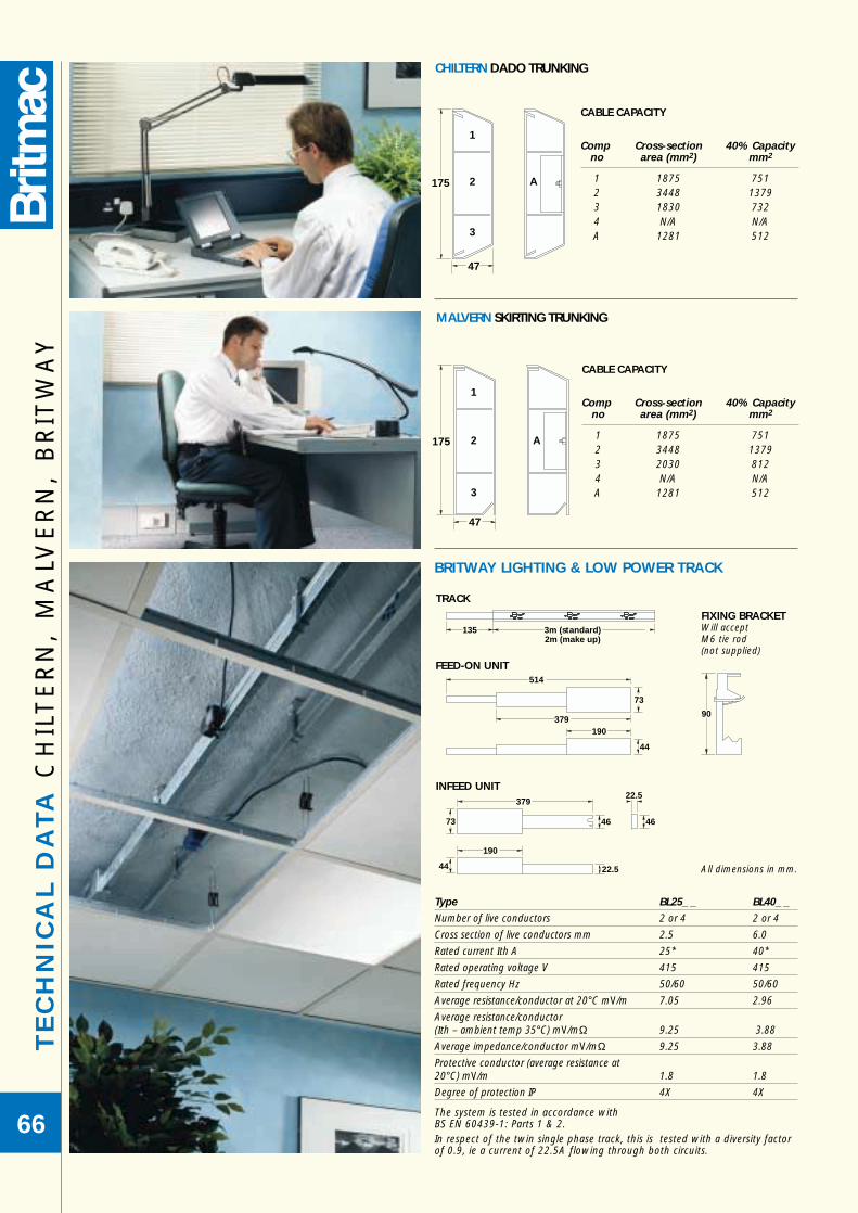
TE
CH
NIC
AL
DA
TA
CH
ILT
ER
N,
MA
LVE
RN
, B
RIT
WA
Y
66
Type BL25_ _ BL40_ _
Number of live conductors 2 or 4 2 or 4
Cross section of live conductors mm 2.5 6.0
Rated current Ith A 25* 40*
Rated operating voltage V 415 415
Rated frequency Hz 50/60 50/60
Average resistance/conductor at 20°C mV/m 7.05 2.96
Average resistance/conductor(Ith – ambient temp 35°C) mV/mΩ 9.25 3.88
Average impedance/conductor mV/mΩ 9.25 3.88
Protective conductor (average resistance at20°C) mV/m 1.8 1.8
Degree of protection IP 4X 4X
The system is tested in accordance withBS EN 60439-1: Parts 1 & 2.In respect of the twin single phase track, this is tested with a diversity factorof 0.9, ie a current of 22.5A flowing through both circuits.
135 3m (standard)2m (make up)
TRACK
46
379
73
22.5
46
190
44 22.5
INFEED UNIT
514
379
73
190
44
FEED-ON UNIT
FIXING BRACKETWill acceptM6 tie rod(not supplied)
90
BRITWAY LIGHTING & LOW POWER TRACK
All dimensions in mm.
CHILTERN DADO TRUNKING
CABLE CAPACITY
Comp Cross-section 40% Capacityno area (mm2) mm2
1 1875 7512 3448 13793 1830 7324 N/A N/AA 1281 512
MALVERN SKIRTING TRUNKING
CABLE CAPACITY
Comp Cross-section 40% Capacityno area (mm2) mm2
1 1875 7512 3448 13793 2030 8124 N/A N/AA 1281 512
175
1
A
47
2
3
47
175
1
A2
3

SPECIFICATION Top Element (Grommet Only) l
Dimensions:
O/A Diameter 150mm
Internal Diameter 120mm
Depth 65mm
Material: High Impact ABS
Colour: RAL 7016
Socket Element
Dimensions:
Plate Diameter 123mm
Depth 37mm (Plate and lower box)
Overall Depth 102mm (including top element)
Material: Powder Coated Zintec Steel Top PlateGalvanised Steel Lower Box
TE
CH
NIC
AL
DA
TA
FL
OO
R G
RO
MM
ET
67
150mm
106mm
2 x 28mmOutlet Holes
37mm
Hole 127mm Dia±2mm
65mm
ROTATING TOP COVER
FLOOR ACCESS GROMMET(3 PART)
SECURITY CLAMP MECHANISMS
ACCESSORY FRONT PLATE (SINGLE)SWITCHED OR UNSWITCHED AVAILABLE
STANDARD BRITMAC TAP OFF UNITS
63 AMP PLUG TOP

4 GANG lWieland Britway Fused Tap-off plug male Connector c/w 3m 3 core 1.5mm LSF cable
DM4S/P
DM4F/W DM4F/P
DM4I/P
DM4SF/W DM4SF/P
DM4SI/P
DM4FI/W DM4FI/P
DM4SFI/W DM4SFI/P
6 GANG lWieland Britway Fused Tap-off plug male Connector c/w 3m 3 core 1.5mm LSF cable
DM6S/P
DM6F/W DM6F/P
DM6I/P
DM6SF/W DM6SF/P
DM6SI/P
DM6FI/W DM6FI/P
DM6SFI/W DM6SFI/P
TE
CH
NIC
AL
DA
TA
DE
SK
MO
DU
LE
68
47.5
600.045.4 615.0
630.0
68.0
450.045.4 465.0
480.0
47.5 68.0
DESK MODULE
FEATURES
• Sheet metal base and cover, with external fixing.
• Sockets and accessories are grid mounted.
• Standard Birch Grey finish.
TAP OFFS
• Units come complete either: a) prewired with 3m, 3 core 1.5mm LSF flex + Britway FusedTap-off plug, or b) prewired with Wieland male connector.
• When a Britway Tap-off plug is fitted, this will be Fusedat 13A (BS1362).
• Wieland only available as standard earth and Fused.
• Clean Earth type will be 3m 4 core 1.5mm LSF cable.
• High Integrity Earth will be 3m conduit c/w 4x4mm2 LSF cable.
SPECIAL FEATURES
• Various colours are available upon request.
• Units can be designed and made to customer specification.
• Please contact Technical Services for further information.

DM4SF/PBCLI
NWT400/WHBAG150
GB3SS2/BGBPT36TE
GR03G
NUMERIC INDEX
69

List No Page No200010BK 55200010BR 55200010GY 55200013BK 55200013BR 55200013GY 5552195-1/D/1* 5552195-2/D/1 5552195-3/D/1 5552229-1/D/4* 5598351-1/H/1 5598351-2/H/1 5598351-3/H/1 5598456-1 5598496-2/E/1 55BA2AE25BL 13BA2AE25BR 13BA2AE25G 13BA2AE38BL 13BA2AE38BR 13BA2AE38G 13BA2AT25BL 13BA2AT25BR 13BA2AT25G 13BA2AT38BL 13BA2AT38BR 13BA2AT38G 13BA2EC25 13BA2EC38 13BA2FS25 13BA2FS38 13BA2RA25 13BA2RA38 13BA2RB25 13BA2RB38 13BA2T25 13BA2T38 13BA2UJ25 13BA2UJ38 13BA3AE25BL 13BA3AE25BR 13BA3AE25G 13BA3AE38BL 13BA3AE38BR 13BA3AE38G 13BA3ASBL 13BA3ASBR 13BA3ASG 13BA3AT25BL 13BA3AT25BR 13
List No Page NoBA3AT25G 13BA3AT38BL 13BA3AT38BR 13BA3AT38G 13BA3EC25 13BA3EC38 13BA3FS25 13BA3FS38 13BA3RA25 13BA3RA38 13BA3RB25 13BA3RB38 13BA3T25 13BA3T38 13BA3UJ25 13BA3UJ38 13BAG150 51, 67BAGS/SP 51, 67BAGSS 51, 67BAGSS3 51, 67BAGSS4 51, 67BAGSS5 51, 67BAGSU 51, 67BAGSU3 51, 67BAGSU4 51, 67BAGSU5 51, 67BCL/ACR 40BCL/ASS 40BCL/BB05 46BCL/BB1 46BCL/SCR 40BCL/SGB 40BCL/SQCR 40BCL/SSS 40BCL/TGB 40BCL1 40, 41BCL1/CP 40BCL1/EB 40BCL1/FAD 40BCL1/FTD 40BCL1/IB 40BCL1/SEL 40BCL2 40, 42BCL2/CP 40BCL2/EB 40BCL2/FAD 40BCL2/FAU 40BCL2/FTD 40BCL2/FTU 40BCL2/IB 40
List No Page NoBCL2/SEL 40BCL2/SER 40BCL3 40BCL3/CP 40BCL3/EB 40BCL3/FAD 40BCL3/FTD 40BCL3/IB 40BCL3/SEL 40BCL4 40, 45BCL4/CP 40BCL4/EB 40BCL4/FAD 40BCL4/FAU 40BCL4/FTD 40BCL4/FTU 40BCL4/IB 40BCL4/SEL 40BCL4/SER 40BCL5 40BCL5/CP 40BCL5/EB 40BCL5/FAD 40BCL5/FAU 40BCL5/FTD 40BCL5/FTU 40BCL5/IB 40BCL5/SEL 40BCL5/SER 40BFC3JR 15BFC3JT 15BFC3JX 15BFC3RB 15BFC3T-1200 15BFC3T-1800 15BFC3T-265 15BFC3T-600 15BFCEC 15BFCJB 15BFT3BL 15BFT3BR 15BFT3G 15BL112 49BL118 49BL132 49BL138 49BL1P2531 49BL1P2535 49BL1P4021 49BL1P4025 49
List No Page NoBL1P4031 49BL1P4035 49BL2P2531 49BL2P2535 49BL2P4021 49BL2P4025 49BL2P4031 49BL2P4035 49BL333 49BL338 49BL3P2531 49BL3P2535 49BL3P4021 49BL3P4025 49BL3P4031 49BL3P4035 49BL40FO 49BL40IN 49BLBE 49BLF110 49BLF130 49BLFB 49BLFT20 49BLT22 49BLT28 49BPCS 9BPCSTE 9BPF1S 9BPF1STE 9BPF2S 9BPF2STE 9BPJF 9BPJFTE 9BPP3 9BPP3TE 9BPP3TE/607 9BPP5F 9BPP5FTE 9BPP5FTE/607 9BPS1S 9BPS2S 9BPT12 9BPT12TE 9BPT18 9BPT18TE 9BPT24 9BPT24TE 9BPT36 9BPT36TE 9BPTFS 9
NU
ME
RIC
IN
DE
X
70

List No Page NoBRS3BL 5BRS3BL/65 5BRS3BR 5BRS3BR/65 5BRS3G 5BRS3G/65 5BRS4BL 5BRS4BL/65 5BRS4BR 5BRS4BR/65 5BRS4G 5BRS4G/65 5BTJ1CA 55BTJ2A 55CD001/BG 32CD001/BK 32CD001/WH 32CD004/_ _ 33CD005/_ _ 32CD006/_ _ 32CD007/_ _ 33CD010/_ _ 32CD010/_ _ 32CD012/_ _ 32CD014/_ _ 32CD015/_ _ 32CD016/_ _ 32CD017/_ _ 32CD018/_ _ 32CD019/_ _ 32CD020/_ _ 32CD021/_ _ 32CD022/_ _ 32CD023/_ _ 32CD024/_ _ 32CD025/_ _ 32CD026/_ _ 32CD027/_ _ 32CD028/_ _ 32CD029/_ _ 33CD030/_ _ 33CD031/_ _ 33CD040/_ _ 33CD041/_ _ 33CD042/_ _ 33CD043/_ _ 33CD044/_ _ 33CD045/_ _ 33CD050/_ _ 33CD051/_ _ 33
List No Page NoCD052/_ _ 33CD060/_ _ 33CD061/_ _ 33CD062/_ _ 33CD063/_ _ 33CD064/_ _ 33CD065/_ _ 33CF1EC40 11CF1JR40 11CF1JT40 11CF1JX40 11CF1RB40 11CF1T40-1200 11CF1T40-1800 11CF1T40-600 11CF1T40-850 11CF1TU40 11CF2EC40 11CF2JR40 11CF2JT40 11CF2JX40 11CF2RB40 11CF2T40-1200 11CF2T40-1800 11CF2T40-600 11CF2T40-800 11CF2TU40 11CF3EC40 11CF3JR40 11CF3JT40 11CF3JX40 11CF3RB40 11CF3T40-1200 11CF3T40-1800 11CF3T40-600 11CF3T40-750 11CF3TU40 11CFSB 11CG12 4CG34 4DM4F/P 53DM4F/W 53DM4FI/P 53DM4FI/W 53DM4I/P 53DM4S/P 53DM4S1/P 53DM4SF/P 53DM4SF/W 53DM4SFI/P 53
List No Page NoDM4SFI/W 53DM6F/P 53DM6F/W 53DM6FI/P 53DM6FI/W 53DM6I/P 53DM6S/P 53DM6SF/P 53DM6SF/W 53DM6SFI/P 53DM6SFI/W 53DM6SI/P 53G1AP 4G1BP 4G1LB 4GB25D/BG 7GB325D/BG 6GB32G/BG 6GB3ALPHA/BG 6GB3ATMM/BG 6GB3BNC/BG 6GB3BP/BG 6GB3EURO/BG 6GB3J3/BG 6GB3J6C/6BG 6GB3J6C/BG 6GB3J6CANG/BG 6GB3LAN2/BG 6GB3S2/607/BG 6GB3S2/BG 6GB3S2BM/BG 6GB3S2CE/BG 6GB3S3/607/BG 6GB3S3/BG 6GB3S3CE/BG 6GB3SN2/607/BG 6GB3SN2/BG 6GB3SN2CE/BG 6GB3SN3/607/BG 6GB3SN3/BG 6GB3SN3CE/BG 6GB3SRCD30/BG 6GB3SS2/607/BG 6GB3SS2/BG 6GB3SS2BM/607/BG 6GB3SS2BM/BG 6GB3SS2CE/BG 6GB3SSN2/607/BG 6GB3SSN2/BG 6GB3SSN2CE/BG 6
List No Page NoGB3T25D/BG 6GB3TBNC/BG 6GB3TLAN1/BG 6GB3TLAN2/BG 6GBALPHA/BG 7GBATMM/BG 7GBBNC/BG 7GBBP/BG 7GBEURO/BG 7GBJ6C/BG 7GBLAN1/BG 7GBS2/607/BG 7GBS2/BG 7GBS2CE/BG 7GBSN2/607/BG 7GBSN2/BG 7GBSN2CE/BG 7GBSS2/607/BG 7GBSS2/BG 7GBSS2CE/BG 7GBSSN2/607/BG 7GBSSN2/BG 7GBSSN2CE/BG 7GRO1BL 4GRO1BR 4GRO1G 4GRO2BL 4GRO2BR 4GRO2G 4GRO3BL 4GRO3BR 4GRO3G 4GRO4BL 4GRO4BR 4GRO4G 4HANDLE/385/BL 55HANDLE/385/BR 55HANDLE/385/GY 55NWT102/_ _ 18NWT103/_ _ 18NWT104/_ _ 18NWT105/_ _ 18NWT110/_ _/ 18NWT111/_ _/ 18NWT112/_ 19NWT113/_ 19NWT114/_ 19NWT120/AA 18NWT120/BK 18NWT120/WH 18
NU
ME
RIC
IND
EX
71

List No Page NoNWT202/_ _ 20NWT203/_ _ 20NWT204/_ _ 20NWT210/_ _/ 20NWT212/_ 21NWT213/_ 21NWT220/AA 20NWT220/BK 20NWT220/WH 20NWT302/_ _ 22NWT303/_ _ 22NWT304/_ _ 22NWT310/_ _/ 22NWT312/_ 23NWT313/_ 23NWT320/AA 22NWT320/BK 22NWT320/WH 22NWT402/_ _ 24NWT403/_ _ 24NWT404/_ _ 24NWT410/_ _/ 24NWT412/_ 25NWT413/_ 25NWT420/AA 24NWT420/BK 24NWT420/WH 24NWT502/_ _ 26NWT503/_ _ 26NWT504/_ _ 26NWT505/_ _ 26NWT510/_ _/ 26NWT511/_ _/ 26NWT512/_ 27NWT513/_ 27NWT514/_ 27NWT520/AA 26NWT520/BK 26NWT520/WH 26NWT550 18, 20NWT551 19, 21NWT553 19, 21, 23, 25, 27NWT555 19, 21, 23, 25, 27NWT560 23, 25, 27NWT566 22, 24, 26NWT82/AA 18, 20, 22, 24, 26NWT82/BK 18, 20, 22, 24, 26NWT82/WH 18, 20, 22, 24, 26PLAIN/385/BL 55PLAIN/385/BR 55
List No Page NoPLAIN/385/GY 55PN1A 55PSS2A 55PSSN2A 55SB615 19, 21, 23, 25, 27SB625 19, 21, 23, 25, 27SK010/_ _ 36SK011/_ _ 36SK016/_ _ 36SK017/_ _ 36SK025/_ _ 37SK026/_ _ 37SK027/_ _ 37SK028/_ _ 37SK029/_ _ 37SK031/_ _ 37SK041 37SK041/_ _ 33SK042/_ _ 37SK043/GV 37SK044 37SK052/_ _ 37SK053/_ _ 37SK056/_ _ 37SK057/_ _ 37SK060 37SK060/_ _ 33SK300/BG 36SK300/BK 36SK300/WH 36SK308/_ _ 36SK310/_ _ 36SK316/_ _ 36SK322/GV 36SK324/GV 36SK330/_ _ 36SK331/GV 36WPP3/U/ 29WPP3/U/AA 29WPP3/U/WH 29WPP556 29WPP557 29WPP558 29WPP559 29WPP560 29WPPS/U/ 29WT008 19, 21, 23, 25, 27WT009 19, 21, 23, 25, 27WT010 19, 21, 23, 25, 27
NU
ME
RIC
IN
DE
X
72

TERMS & CONDITIONS OF SALE OF GOODSl
HOMEl
1 Contract Terms Quotations & Orders1.1 Unless other terms and conditions are expressly accepted by Electrium Sales Ltd. by means of a specific
written amendment hereto signed by Electrium Sales Ltd. or a Director of Electrium Sales Ltd. the contractwill be on the terms and conditions set out below (“the Contract Terms”) to the exclusion of any otherterms and conditions (except those implied in favour of a seller which are not inconsistent with theContract Terms) whether or not the same are endorsed upon, delivered with or referred to in any purchaseorder or other document delivered or sent by the Customer to Electrium Sales Ltd. or by Electrium SalesLtd. to the Buyer reference made by Electrium Sales Ltd. to the Customer’s order, specification or likedocument will not be deemed to imply that any terms or conditions endorsed upon, delivered with orreferred to in such order, specification or like document will have effect to the exclusion or amendment ofthe Contract Terms. No variation, addition or modification of the Contract Terms. conditions shall bebinding on Electrium Sales Ltd. unless such variation, addition or modification be agreed to in writing underthe signature of a Director of Electrium Sales Ltd.
1.2 Any quotation is given on the basis that no contract will come into existence until the Customer places anorder pursuant thereto. Any quotation is valid for a period of 30 days only from its date provided thatElectrium Sales Ltd. has not previously withdrawn it.
2 PriceThe price of Goods supplied hereunder (“the Goods”) is exclusive of VAT or any successor tax thereto unlessotherwise agreed in writing. The price for the Goods shall be (unless otherwise agreed by Electrium Sales Ltd.in writing) the list price of Electrium Sales Ltd. current at the date of despatch and in the case of an order fordelivery by instalments the price payable for each instalment shall be Electrium Sales Ltd’s list price current atthe date of despatch for each instalment. All prices are based on standard pack sizes and quantities andElectrium Sales Ltd. reserves the right to levy an additional charge if such packs must be broken up to fulfil anorder. The price of Goods is inclusive of costs of carriage to the Customer’s premises in Great Britain andNorthern Ireland except on individual orders having a net value calculated by reference to the Company’s mostrecent price list of less than £200 (excluding VAT) which shall be subject to an additional charge of £15.00(excluding VAT) to cover carriage and packing. The price of Goods is based on the costs of materials, labour,sub-contracts, transport, taxes, duties and currency exchange rates ruling at the date of the quotation.Electrium Sales Ltd. reserves the right to amend the contract price to take account of any variations in thesecosts or the imposition of any new taxes or duties occurring from whatever cause before delivery of the Goods.3 PaymentThe due date for payment shall be the last day of the month following the month of despatch of Goodssupplied by Electrium Sales Ltd. Payment made before the due date for payment shall be subject to a settlementdiscount of 2.5%. VAT is calculated on the discounted value of the invoice and is not subject to settlementdiscount. Interest at an annual rate of 3% per month will accrue daily and be calculated on a daily basis onoverdue accounts from the date of invoice until payment. Notwithstanding any Contract Term allowing theCustomer credit payment shall become due and payable to Electrium Sales Ltd. immediately upon thetermination of the contract. The Customer shall not be entitled to exercise any right of set-off or lien or anysimilar right or claim in connection with the Goods or the price payable therefor.4 Packing MaterialsPacking cases and cartons will be provided free of charge by Electrium Sales Ltd. All pallets used shall remain atall times the property of Electrium Sales Ltd. and are to be returned to Electrium Sales Ltd. on demand in goodcondition. Electrium Sales Ltd. reserves the right to alter the method of packing without reference to theCustomer.5 Damage or Loss in TransitElectrium Sales Ltd. will not be liable in respect of any damage or discrepancy, shortage or loss in transit or anyclaim that the Goods delivered do not otherwise comply with the contract unless the Customer shall haveinformed the Company in writing, telex or facsimile as follows:(a) Within three days of delivery in the event of any damage, discrepancy or shortage.(b) Within seven days of delivery in the event that the Goods do not comply with the contract,and(c) Within twenty-one days of receipt of the Company’s invoice in the event of non-delivery.Where the Goods are accepted from the Company’s carriers they shall be deemed to have been checked by thePurchaser and accepted unless the delivery receipt is signed and endorsed ‘unexamined’ and the packing and itscontents are retained for later inspection.6 DeliveryThe place of delivery for Goods shall be the Customer’s premises or as otherwise agreed by Electrium Sales Ltd.in writing. The time of delivery will be as agreed between the parties or if no such agreement has been reachedwill be within a reasonable time and the Company will be entitled to make delivery by instalments. Where thecustomer requires delivery next day a charge of £13.50 will be made. In no circumstances will Electrium SalesLtd. be liable for loss or damage of any kind whatsoever caused directly or indirectly by any delay in the deliveryof Goods, nor unless such delay exceeds 180 days will any delay entitle the Customer to terminate or rescindthe contract. Notwithstanding any other Contract Term, risk in the Goods shall pass to the Buyer when theGoods are delivered to the Customer or its agent.7 Title of GoodsUntil Electrium Sales Ltd. has been paid in full for the Goods comprised in this and/or any other contractbetween the Customer and Electrium Sales Ltd, the Customer shall hold the Goods in a fiduciary capacity asbailee for Electrium Sales Ltd, and:(i) the title to, ownership of, and the property in, the Goods shall remain vested in Electrium Sales Ltd.
(notwithstanding delivery of the same and parting of the risk therein to the Customer) until payment in fullfor all Goods comprised in this and every other contract between Electrium Sales Ltd. and the Customerhas been received by Electrium Sales Ltd.
(ii) The Customer shall be in possession of the Goods as Electrium Sales Ltd’s bailee. If so required theCustomer shall store the Goods for Electrium Sales Ltd. without charge to Electrium Sales Ltd. separatefrom any goods which are the property of the Customer and/or any third party and ensure that they areclearly marked and identified as belonging to Electrium Sales Ltd.
(iii) Electrium Sales Ltd. reserves the right to require the Customer to return the Goods and may recover andsell the same at any time. For that purpose Electrium Sales Ltd’s servants and agents together with allnecessary and appropriate transport shall be entitled to unrestricted access to the Customer’s premises andany other location where the Goods are situated to take possession of the Goods and, if necessary,dismantle the Goods from any article or articles to which they may have been attached and to remove theGoods from the Customer’s premises.
(iv) Prior to the property in the Goods passing to the Customer Electrium Sales Ltd. permits the Customer todeliver the Goods to a third party pursuant to a bona fide and arms-length agreement to re-sell the Goodsand allows the Customer to convert or incorporate the Goods into or mix the Goods with other goods butsuch liberty will cease upon the termination of the contract.
(v) Where Electrium Sales Ltd. is unable to determine whether any goods are Electrium Sales Ltd’s Goods theCustomer shall be deemed to have sold all goods of the kind sold by Electrium Sales Ltd. to the Customerin the order in which they were invoiced to the Customer.
8 Descriptive MatterDescriptive matter, illustrations, dimensions and weights issued by Electrium Sales Ltd. are to be regarded asbeing for guidance only and cannot be held as binding in any way. In pursuance of Electrium Sales Ltd’s policyof product improvement Electrium Sales Ltd. reserves the right to alter patterns and designs without prior notice.9 GuaranteeElectrium Sales Ltd. will make good by replacement (or its option by repair) defects which under proper useappear in the Goods within a period of twelve calendar months after the Goods have been despatched, andwhich arise solely from faulty design, materials or workmanship provided always that defective Goods havebeen returned to Electrium Sales Ltd. and Electrium Sales Ltd. was notified of the defect or suspected defectimmediately the same became known to the Customer. The cost of carriage on such returned Goods and thecost of re-delivery of the repaired or new Goods to be borne by Electrium Sales Ltd. Save for the ElectriumSales Ltd’s control equipment which has been correctly repaired or modified by the use of standard partssupplied by Electrium Sales Ltd. for such purpose, Electrium Sales Ltd. excludes all liability in respect of anyGoods which have been re-finished and dismantled or altered in any way or if the Goods were improperlyinstalled or connected or if the Customer fails to observe or perform the requirements of any maintenanceprocedures relating to the Goods. Any Goods replaced will belong to Electrium Sales Ltd. Any repaired orreplacement Goods will be guaranteed on these terms for the unexpired portion of the twelve month period.In addition, the obligations of Electrium Sales Ltd. under this condition will not apply if the Customer is inbreach of this or any other contract with Electrium Sales Ltd.. Subject to this condition, all conditions,warranties and representations, whether express or implied (by statute or otherwise) relating to the Goods arehereby excluded insofar as the same can be excluded without such exclusion being void or unenforceable.Electrium Sales Ltd. will be under no liability under the contract for any personal injury, death, loss ordamage of any kind whatsoever (other than death or personal injury resulting from Electrium SalesLtd’s negligence) whether consequential or otherwise including but not limited to loss of profits andElectrium Sales Ltd. hereby excludes all conditions, warranties and stipulations express or implied,statutory, customary or otherwise which but for such exclusion would or might subsist in favour of the
Customer except that such exclusion will not apply to any implied condition that Electrium Sales Ltd.has or will have the right to sell the Goods when the property is to pass; or when Electrium SalesLtd. deals as a consumer (as defined in section 12 of the Unfair Contract Terms Act 1977), any impliedterm relating to the conformity of the Goods with their description or sample or as to their quality orfitness for a particular purpose. In no circumstances will Electrium Sales Ltd. or its employees, agentsor sub-contractors be liable for any loss or damage of any kind whatsoever (other than death orpersonal injury resulting from Electrium Sales Ltd’s negligence) whether consequential or otherwisecaused directly or indirectly by any negligence or other tortious act or breach of statutory duty onthe part of Electrium Sales Ltd. or on the part of any of its employees, agents or sub-contractors inconnection with or arising out of the manufacture or supply of the Goods or in connection with anystatement given or made (or advice not given or made) by or on behalf of Electrium Sales Ltd.10 PatentsElectrium Sales Ltd. will indemnify the Customer against any claim of infringement of letters patent, registereddesign, trademark or copyright (existing at the date of the contract) arising from the use or sale of any article ormaterials supplied by Electrium Sales Ltd. to the Customer and against all costs and damages which theCustomer may incur in any action for such infringement or for which the Customer may become liable in anysuch action provided always that this indemnity shall not apply to any infringement which arises in connectionwith any design or instruction issued or given by the Customer to Electrium Sales Ltd. or to the use of sucharticle or material in a manner or for a purpose outside the UK or to any infringement which is due to the useof such article or material in association or combination with any other article or material not supplied byElectrium Sales Ltd. and provided also that this indemnity is conditional on the Customer making no admissionin respect of such alleged infringement and giving Electrium Sales Ltd. the earliest possible notice in writing ofany claim being made or action threatened or brought against the Customer and on the Customer permittingElectrium Sales Ltd. at Electrium Sales Ltd’s expense to conduct any litigation that may ensue and all negotiationsfor the settlement of a claim.The Customer warrants that any design or instruction issued or given by the Customer shall not be such as willcause Electrium Sales Ltd. to infringe any letters patent, registered design, trademark or copyright in theexecution of the Customer’s order and the Customer agrees to indemnify and keep Electrium Sales Ltd.indemnified against all liability in the event that such warrant is found to be untrue, misleading or breached.11 AdviceAdvice which Electrium Sales Ltd. or its agents may give to the Customer shall be given in good faith butElectrium Sales Ltd. shall not be liable for any loss or damage arising directly or indirectly therefrom orattributable thereto unless contained in any written representation or statement issued directly by Electrium Sales Ltd.12 SafetyThe Customer shall ensure that any modifications whatsoever made to the Goods supplied hereunder complywith the requirements of any applicable Safety Regulations. Plugs supplied hereunder shall be so connected asto ensure that they are safe and in full compliance with any applicable Safety Regulations. The Customer shallensure that any kits supplied hereunder are so assembled as to ensure that the assembled product is safe andcomplies with the requirements of any applicable Safety Regulations. Without prejudice to the above provisions,where Electrium Sales Ltd. provides the Customer with information about the use for which Goods are designedand have been tested and about any conditions to ensure that when put to that use they would be safe andwithout risk to health, the Customer shall use the Goods accordingly and comply with the said conditions.To be properly used the Goods shall be selected, installed, commissioned and maintained in accordance withgood engineering practice and under the supervision of suitably qualified personnel.13 Statutory and other RegulationsIf the cost to Electrium Sales Ltd. of performing its obligations under any contract shall be increased or reducedby reason of making or amendment after the date of its quotation of any law or of any other order, regulationor bye-law having the force of law that shall affect the performance of Electrium Sales Ltd’s contractualobligations, the amount of such increase or reduction shall be added to or deducted from the contract price asthe case may be.14 CancellationIf the Customer cancels, extends or delays or purports to cancel, extend or delay the contract or part thereof, orfails to take delivery of any Goods at the time agreed (if any) or if no time is agreed within a reasonable time,then the Customer will be liable (without prejudice to any other rights of Electrium Sales Ltd. to claim damages)to indemnify and keep indemnified Electrium Sales Ltd. against any resulting loss, damage or expense incurredby Electrium Sales Ltd. in connection with the supply or non-supply of the Goods including the cost of anymaterial, used or intended to be used therefor and the cost of labour and other overheads including a percentagein respect of profit. If Electrium Sales Ltd. is unable (whether temporarily or permanently) to procure any servicesor goods necessary to enable it to supply the Goods or if the supply of the Goods is prevented or hindered byreason of any cause beyond Electrium Sales Ltd’s reasonable control which for the avoidance of doubt andwithout prejudice to the generality of the foregoing shall include governmental action, war, riot, civil commotion,fire, flood, epidemic, labour disputes including labour disputes involving the work force or any part thereof ofElectrium Sales Ltd, restraints or delays affecting shipping or carriers, currency restrictions and Act of God,Electrium Sales Ltd. may cancel the contract by notice in writing to the Customer so far as it relates to Goodsnot then supplied or work not then done and such cancellation shall not give rise to any claims by the Customerprovided that the Customer shall remain liable to pay for Goods delivered prior to the date of such cancellation.15 General(a) The headings herein are inserted for convenience only and shall not affect the interpretation of the
Contract Terms.(b) Should any clause contained in the Contract Terms be held to be invalid such invalidity will not affect the
validity of the remaining clauses.(c) Any dispute arising out of this contract or the Contract Terms shall be referred in writing to an independent
arbitrator who shall be appointed by agreement between Electrium Sales Ltd. and the Customer or indefault of agreement by the President for the time being of the Institute of Electrical Engineers whosedecision shall be binding on both parties.
(d) The formation, interpretation and operation of the contract will be subject to English Law and theCustomer submits himself to the non-exclusive jurisdiction of the English Courts.
(e) Electrium Sales Ltd. will be entitled to assign sub-contract or sub-let the contract or any part thereof.(f) Failure by Electrium Sales Ltd. to enforce any of the Contract Terms will not be construed as a waiver of
any of its rights hereunder.
EXPORTl
All Contract Terms set out above apply to overseas transactions (ie sales outside the United Kingdom), whereappropriate, except the following:1.2 Any quotation is given on the basis that no contract will come into existence until Electrium Sales Ltd.
despatches an acknowledgement of order to the Customer. Any quotation is valid for a period of 30 daysonly from its date provided that Electrium Sales Ltd. has not previously withdrawn it.
2 PriceThe price of Goods includes the cost of packing for shipment FOB British Port or Airport except that ordershaving a net value of £500 and below shall be subject to an additional charge to cover packing and carriage.No allowance will be made in lieu of transportation if the Customer accepts delivery at the factory, containerdepot or at any other inland destination or provides his own transportation or where packing of a lesser standardis required.3 PaymentFirst orders from overseas Customers should be accompanied by bank references to enable payment terms tobe agreed. Unless otherwise agreed in writing, payment is due on delivery. Goods shall be deemed to havebeen delivered when the invoice has been presented in the United Kingdom accompanied by the appropriatedocuments of title.16 OthersThe Goods will be sold FOB British Port or Airport and the Seller will be under no obligation to give the Buyernotice as specified in Section 32(3) of the Sale of Goods Act 1979. CIF or C & F arrangements can be made ifrequested by the Customer, at cost, and Electrium Sales Ltd. will, on receipt of Customer’s indemnity, take allreasonable steps to recover from the Underwriters any loss or damage for which they may be liable.The Customer shall be solely responsible for complying with all legislation and regulations governing theimportation of the Goods into the country of destination including import and export licences and the paymentof duties thereon including but not limited to customs duties and VAT. The Customer shall indemnify ElectriumSales Ltd. against all costs claims and demands arising out of any breach by the Customer of this Agreement.
CONDITIONS OF USEThe products listed in this publication should be installed by suitably qualified personnel in accordancewith the requirements of relevant legislation, regulations (including the IEE Wiring Regulations) andthe accepted practice in the industry. Any further information which may be required about the usefor which any specific product has been designed and tested, or about conditions of use, is availableon request. In pursuance of our policy of continuing product improvement, equipment described inthis publication is subject to change without notification.

ELECTRIUM SALES LIMITEDLichfield Road Brownhills West Midlands WS8 6JZ England.eMail: [email protected] Web: www.electrium.co.uk
Telephone: 01543 455000 Facsimile: 01543 455001
UK SALESTelephone: 01543 455218 Facsimile: 01543 453119
eMail: [email protected]
EXPORT SALESTelephone: +44 1543 455049 Facsimile: +44 1543 455048
eMail: [email protected]
DUBAI OFFICETelephone: +971 4 2666403 Facsimile: +971 4 2668031
DUBLIN OFFICETelephone: +353 1 8208047 Facsimile: +353 1 8208107
SINGAPORE OFFICETelephone: +65 2544905 Facsimile: +65 2546570
Although every effort has been made to ensure accuracy in the compilation of thetechnical detail within this publication, specifications and performance data are
constantly changing. Latest details can be obtained from Crabtree.
Publication No.CM1966 08/01Printed in England.