Embed Size (px)
Citation preview

8/4/2019 C7 Principles
http://slidepdf.com/reader/full/c7-principles 1/298
CHAPTER 2THE SS7 NETWORK
CHAPTER 3SS7 4 LEVEL MODEL
CHAPTER 4SS7 NETWOR
ADDRESSING AND R
CHAPTER 1ROLE OF SIGNALLING
SYSTEM

8/4/2019 C7 Principles
http://slidepdf.com/reader/full/c7-principles 2/298
CHAPTER 7TRANS. CAP’S. AP AND
MAP
CHAPTER 8GSM NETWORK OVERVIEW
TO SS7
CHAPTER 6SIGNALLING CONNECTION
CONTROL PART

8/4/2019 C7 Principles
http://slidepdf.com/reader/full/c7-principles 3/298
Principles of C7
Training Manual
Issue 5 Revision 0
FOR TRAININGPURPOSES ONLY
CP03

8/4/2019 C7 Principles
http://slidepdf.com/reader/full/c7-principles 4/298

8/4/2019 C7 Principles
http://slidepdf.com/reader/full/c7-principles 5/298
FOR TRAININGPURPOSES ONLY
Issue 5 Revision 0
T r ai ni n
gM
an
u al
P r i n ci pl e s o
f C 7
I s s u e 5
R ev i s i
on 0
C o ur s
e
Principles of C7
Course
CP03
P o s i t i n
m a r k f o r T E D s p i n e
TrainingManual

8/4/2019 C7 Principles
http://slidepdf.com/reader/full/c7-principles 6/298

8/4/2019 C7 Principles
http://slidepdf.com/reader/full/c7-principles 7/298
EMOTOROLA LTD. 2001
CP03: Principles of C7
FOR TRAINING PURPOSES ONLY i
Issue 5 Revision 0
CP03
Principles of C7
E Motorola 1993, 1994, 1995, 1996, 1997, 1998, 1999
All Rights Reserved
Printed in the U.K.

8/4/2019 C7 Principles
http://slidepdf.com/reader/full/c7-principles 8/298
Issue 5 Revision 0
EMOTOROLA LTD. 2001
CP03: Principles of C7
FOR TRAINING PURPOSES ONLYii
Copyrights, notices and trademarks
Copyrights
The Motorola products described in this document may include copyrighted Motorola computer
programs stored in semiconductor memories or other media. Laws in the United States and other
countries preserve for Motorola certain exclusive rights for copyright computer programs, including the
exclusive right to copy or reproduce in any form the copyright computer program. Accordingly, any
copyright Motorola computer programs contained in the Motorola products described in this document
may not be copied or reproduced in any manner without the express written permission of Motorola.
Furthermore, the purchase of Motorola products shall not be deemed to grant either directly or by
implication, estoppel or otherwise, any license under the copyrights, patents or patent applications of
Motorola, except for the rights that arise by operation of law in the sale of a product.
Restrictions
The software described in this document is the property of Motorola. It is furnished under a licenseagreement and may be used and/or disclosed only in accordance with the terms of the agreement.
Software and documentation are copyright materials. Making unauthorized copies is prohibited by
law. No part of the software or documentation may be reproduced, transmitted, transcribed, stored
in a retrieval system, or translated into any language or computer language, in any form or by any
means, without prior written permission of Motorola.
AccuracyWhile reasonable efforts have been made to assure the accuracy of this document, Motorola
assumes no liability resulting from any inaccuracies or omissions in this document, or from the use
of the information obtained herein. Motorola reserves the right to make changes to any products
described herein to improve reliability, function, or design, and reserves the right to revise this
document and to make changes from time to time in content hereof with no obligation to notify any
person of revisions or changes. Motorola does not assume any liability arising out of the application
or use of any product or circuit described herein; neither does it convey license under its patent
rights of others.
Trademarks
and MOTOROLA are trademarks of Motorola Inc.
UNIX is a registered trademark in the United States and other countries, licensed exclusively throughX/Open Company Limited.
Tandem, Integrity, Integrity S2, and Non-Stop-UX are trademarks of Tandem Computers
Incorporated.
X Window System, X and X11 are trademarks of the Massachusetts Institute of Technology.
Looking Glass is a registered trademark of Visix Software Ltd.
OSF/Motif is a trademark of the Open Software Foundation.
Ethernet is a trademark of the Xerox Corporation.
Wingz is a trademark and INFORMIX is a registered trademark of Informix Software Ltd.
SUN, SPARC, and SPARCStation are trademarks of Sun Microsystems Computer Corporation.
IBM is a registered trademark of International Business Machines Corporation.
HP is a registered trademark of Hewlett Packard Inc.

8/4/2019 C7 Principles
http://slidepdf.com/reader/full/c7-principles 9/298
Issue 5 Revision 0
EMOTOROLA LTD. 2001
CP03: Principles of C7
FOR TRAINING PURPOSES ONLY iii
General information 1. . . . . . . . . . . . . . . . . . . . . . . . . . . . . . . . . . . . . . . . . . . . . . . . . . . . . . . . .
Important notice 1. . . . . . . . . . . . . . . . . . . . . . . . . . . . . . . . . . . . . . . . . . . . . . . . . . . . . .
Purpose 1. . . . . . . . . . . . . . . . . . . . . . . . . . . . . . . . . . . . . . . . . . . . . . . . . . . . . . . . . . . . .
About this manual 1. . . . . . . . . . . . . . . . . . . . . . . . . . . . . . . . . . . . . . . . . . . . . . . . . . . . .
Cross references 2. . . . . . . . . . . . . . . . . . . . . . . . . . . . . . . . . . . . . . . . . . . . . . . . . . . . . .
Text conventions 2. . . . . . . . . . . . . . . . . . . . . . . . . . . . . . . . . . . . . . . . . . . . . . . . . . . . . .
First aid in case of electric shock 3. . . . . . . . . . . . . . . . . . . . . . . . . . . . . . . . . . . . . . . . . . . . . .
Reporting safety issues 4. . . . . . . . . . . . . . . . . . . . . . . . . . . . . . . . . . . . . . . . . . . . . . . . . . . . . .
Warnings and cautions 5. . . . . . . . . . . . . . . . . . . . . . . . . . . . . . . . . . . . . . . . . . . . . . . . . . . . . .
General warnings 6. . . . . . . . . . . . . . . . . . . . . . . . . . . . . . . . . . . . . . . . . . . . . . . . . . . . . . . . . . .
Human exposure to radio frequency energy (PCS1900 only) 8. . . . . . . . . . . . . . . . . . . . . .
Beryllium health and safety precautions 11. . . . . . . . . . . . . . . . . . . . . . . . . . . . . . . . . . . . . . . .
General cautions 13. . . . . . . . . . . . . . . . . . . . . . . . . . . . . . . . . . . . . . . . . . . . . . . . . . . . . . . . . . .
Devices sensitive to static 14. . . . . . . . . . . . . . . . . . . . . . . . . . . . . . . . . . . . . . . . . . . . . . . . . . . .
Motorola GSM manual set 15. . . . . . . . . . . . . . . . . . . . . . . . . . . . . . . . . . . . . . . . . . . . . . . . . . .Introduction 15. . . . . . . . . . . . . . . . . . . . . . . . . . . . . . . . . . . . . . . . . . . . . . . . . . . . . . . . . .
Generic manuals 15. . . . . . . . . . . . . . . . . . . . . . . . . . . . . . . . . . . . . . . . . . . . . . . . . . . . . .
Tandem OMC 15. . . . . . . . . . . . . . . . . . . . . . . . . . . . . . . . . . . . . . . . . . . . . . . . . . . . . . . .
Scaleable OMC 16. . . . . . . . . . . . . . . . . . . . . . . . . . . . . . . . . . . . . . . . . . . . . . . . . . . . . . .
Related manuals 16. . . . . . . . . . . . . . . . . . . . . . . . . . . . . . . . . . . . . . . . . . . . . . . . . . . . . .
Service manuals 16. . . . . . . . . . . . . . . . . . . . . . . . . . . . . . . . . . . . . . . . . . . . . . . . . . . . . .
Category number 17. . . . . . . . . . . . . . . . . . . . . . . . . . . . . . . . . . . . . . . . . . . . . . . . . . . . .
Catalogue number 17. . . . . . . . . . . . . . . . . . . . . . . . . . . . . . . . . . . . . . . . . . . . . . . . . . . .
Ordering manuals 17. . . . . . . . . . . . . . . . . . . . . . . . . . . . . . . . . . . . . . . . . . . . . . . . . . . . .
Chapter 1
Role of Signalling SystemNo 7 in GSM i. . . . . . . . . . . . . . . . . . . . . . . . . . . . . . . . . . . . . . . . . . . . . . . . . . . . . . . .
Objectives 1–1. . . . . . . . . . . . . . . . . . . . . . . . . . . . . . . . . . . . . . . . . . . . . . . . . . . . . . . . . . . . . . . . .
SS7 in GSM 1–2. . . . . . . . . . . . . . . . . . . . . . . . . . . . . . . . . . . . . . . . . . . . . . . . . . . . . . . . . . . . . . .
GSM Network Overview 1–2. . . . . . . . . . . . . . . . . . . . . . . . . . . . . . . . . . . . . . . . . . . . . . .
The Network Switching Subsystem 1–4. . . . . . . . . . . . . . . . . . . . . . . . . . . . . . . . . . . . . . . . . . . .
The Base Station System 1–6. . . . . . . . . . . . . . . . . . . . . . . . . . . . . . . . . . . . . . . . . . . . . . . . . . . .
Network Management Centre (NMC) 1–8. . . . . . . . . . . . . . . . . . . . . . . . . . . . . . . . . . . . . . . . . .
2Mbits PCM 1–10. . . . . . . . . . . . . . . . . . . . . . . . . . . . . . . . . . . . . . . . . . . . . . . . . . . . . . . . . . . . . . . .
SS7 Interfaces 1–12. . . . . . . . . . . . . . . . . . . . . . . . . . . . . . . . . . . . . . . . . . . . . . . . . . . . . . . . . . . . .
GSM Interface Names 1–14. . . . . . . . . . . . . . . . . . . . . . . . . . . . . . . . . . . . . . . . . . . . . . . . . . . . . . .Interface Names 1–14. . . . . . . . . . . . . . . . . . . . . . . . . . . . . . . . . . . . . . . . . . . . . . . . . . . . . .
Chapter 2The SS7 Network i. . . . . . . . . . . . . . . . . . . . . . . . . . . . . . . . . . . . . . . . . . . . . . . . . . .
Objectives 2–1. . . . . . . . . . . . . . . . . . . . . . . . . . . . . . . . . . . . . . . . . . . . . . . . . . . . . . . . . . . . . . . . .
Main Requirements of SS7 2–2. . . . . . . . . . . . . . . . . . . . . . . . . . . . . . . . . . . . . . . . . . . . . . . . . .
Signalling Elements in a Network 2–4. . . . . . . . . . . . . . . . . . . . . . . . . . . . . . . . . . . . . . . . . . . . .
Signalling Point/Signalling Transfer Point 2–6. . . . . . . . . . . . . . . . . . . . . . . . . . . . . . . . . . . . . . .
Signalling Point Code 2–8. . . . . . . . . . . . . . . . . . . . . . . . . . . . . . . . . . . . . . . . . . . . . . . . . . . . . . .

8/4/2019 C7 Principles
http://slidepdf.com/reader/full/c7-principles 10/298
Issue 5 Revision 0
EMOTOROLA LTD. 2001
CP03: Principles of C7
FOR TRAINING PURPOSES ONLYiv
Format of Signalling Point Code 2–10. . . . . . . . . . . . . . . . . . . . . . . . . . . . . . . . . . . . . . . . . . . . . .
Numbering of International Signalling Points 2–10. . . . . . . . . . . . . . . . . . . . . . . . . . . . . .
Signalling Link and Link Sets 2–12. . . . . . . . . . . . . . . . . . . . . . . . . . . . . . . . . . . . . . . . . . . . . . . . .
SS7 Signalling Link Types 2–12. . . . . . . . . . . . . . . . . . . . . . . . . . . . . . . . . . . . . . . . . . . . . .
Signalling Route and Route Set 2–14. . . . . . . . . . . . . . . . . . . . . . . . . . . . . . . . . . . . . . . . . . . . . . .
Message Routing across a network 2–16. . . . . . . . . . . . . . . . . . . . . . . . . . . . . . . . . . . . . . . . . . .
Signalling Methods 2–18. . . . . . . . . . . . . . . . . . . . . . . . . . . . . . . . . . . . . . . . . . . . . . . . . . . . . . . . . .
E1 PCM 2–20. . . . . . . . . . . . . . . . . . . . . . . . . . . . . . . . . . . . . . . . . . . . . . . . . . . . . . . . . . . . . . . . . . .
SCP Database 2–22. . . . . . . . . . . . . . . . . . . . . . . . . . . . . . . . . . . . . . . . . . . . . . . . . . . . . . . . . . . . .
Service Switching Point (SSP) 2–22. . . . . . . . . . . . . . . . . . . . . . . . . . . . . . . . . . . . . . . . . .
Service Control Point (SCP) 2–22. . . . . . . . . . . . . . . . . . . . . . . . . . . . . . . . . . . . . . . . . . . .
The SS7 Network 2–24. . . . . . . . . . . . . . . . . . . . . . . . . . . . . . . . . . . . . . . . . . . . . . . . . . . . . . . . . . .
Chapter 3SS7 4 Level Model i. . . . . . . . . . . . . . . . . . . . . . . . . . . . . . . . . . . . . . . . . . . . . . . . . .
Objectives 3–1. . . . . . . . . . . . . . . . . . . . . . . . . . . . . . . . . . . . . . . . . . . . . . . . . . . . . . . . . . . . . . . . .
Protocols 3–2. . . . . . . . . . . . . . . . . . . . . . . . . . . . . . . . . . . . . . . . . . . . . . . . . . . . . . . . . . . . . . . . . .
Protocol Layers of the OSI 7 Model 3–4. . . . . . . . . . . . . . . . . . . . . . . . . . . . . . . . . . . . . . . . . . .
Protocol Comparison of OSI to SS7 3–6. . . . . . . . . . . . . . . . . . . . . . . . . . . . . . . . . . . . . . . . . . .
SS7 to OSI Overview 3–8. . . . . . . . . . . . . . . . . . . . . . . . . . . . . . . . . . . . . . . . . . . . . . . . . . . . . . .
MTP Layer 1 3–10. . . . . . . . . . . . . . . . . . . . . . . . . . . . . . . . . . . . . . . . . . . . . . . . . . . . . . . . . . . . . . .
MTP Layer 2 3–12. . . . . . . . . . . . . . . . . . . . . . . . . . . . . . . . . . . . . . . . . . . . . . . . . . . . . . . . . . . . . . .
MTP Layer 2 Functionality 3–14. . . . . . . . . . . . . . . . . . . . . . . . . . . . . . . . . . . . . . . . . . . . . . . . . . .
MTP Layer 3 3–16. . . . . . . . . . . . . . . . . . . . . . . . . . . . . . . . . . . . . . . . . . . . . . . . . . . . . . . . . . . . . . .
MTP Layer 3 Functionality 3–18. . . . . . . . . . . . . . . . . . . . . . . . . . . . . . . . . . . . . . . . . . . . . . . . . . .
Traffic Handling 3–18. . . . . . . . . . . . . . . . . . . . . . . . . . . . . . . . . . . . . . . . . . . . . . . . . . . . . . .
Signalling Network Management 3–18. . . . . . . . . . . . . . . . . . . . . . . . . . . . . . . . . . . . . . . .
MTP Functionality 3–20. . . . . . . . . . . . . . . . . . . . . . . . . . . . . . . . . . . . . . . . . . . . . . . . . . . . . . . . . .
Message discrimination 3–20. . . . . . . . . . . . . . . . . . . . . . . . . . . . . . . . . . . . . . . . . . . . . . . .
Message Transfer Part 3–22. . . . . . . . . . . . . . . . . . . . . . . . . . . . . . . . . . . . . . . . . . . . . . . . . . . . . .
SS7 layer 4 3–24. . . . . . . . . . . . . . . . . . . . . . . . . . . . . . . . . . . . . . . . . . . . . . . . . . . . . . . . . . . . . . . .
SS7 to OSI layers 3–26. . . . . . . . . . . . . . . . . . . . . . . . . . . . . . . . . . . . . . . . . . . . . . . . . . . . . . . . . .
Signalling Connection Control Part 3–28. . . . . . . . . . . . . . . . . . . . . . . . . . . . . . . . . . . . . . . . . . . .
Transaction Capabilities Application Part 3–30. . . . . . . . . . . . . . . . . . . . . . . . . . . . . . . . . . . . . . .Mobile Application Part (MAP) 3–32. . . . . . . . . . . . . . . . . . . . . . . . . . . . . . . . . . . . . . . . . . . . . . . .
MAP services 3–34. . . . . . . . . . . . . . . . . . . . . . . . . . . . . . . . . . . . . . . . . . . . . . . . . . . . . . . . . . . . . .
MAP Services and Primitives 3–36. . . . . . . . . . . . . . . . . . . . . . . . . . . . . . . . . . . . . . . . . . . . . . . . .
Chapter 4SS7 Network Addressing and Routing i. . . . . . . . . . . . . . . . . . . . . . . . . . . . . . . .
Objectives 4–1. . . . . . . . . . . . . . . . . . . . . . . . . . . . . . . . . . . . . . . . . . . . . . . . . . . . . . . . . . . . . . . . .
Network Addressing 4–2. . . . . . . . . . . . . . . . . . . . . . . . . . . . . . . . . . . . . . . . . . . . . . . . . . . . . . . . .
Point Codes 4–4. . . . . . . . . . . . . . . . . . . . . . . . . . . . . . . . . . . . . . . . . . . . . . . . . . . . . . . . . . . . . . . .

8/4/2019 C7 Principles
http://slidepdf.com/reader/full/c7-principles 11/298
Issue 5 Revision 0
EMOTOROLA LTD. 2001
CP03: Principles of C7
FOR TRAINING PURPOSES ONLY v
Point Codes 4–6. . . . . . . . . . . . . . . . . . . . . . . . . . . . . . . . . . . . . . . . . . . . . . . . . . . . . . . . . . . . . . . .
Global Title 4–8. . . . . . . . . . . . . . . . . . . . . . . . . . . . . . . . . . . . . . . . . . . . . . . . . . . . . . . . . . . . . . . .
Subsystem Numbering 4–10. . . . . . . . . . . . . . . . . . . . . . . . . . . . . . . . . . . . . . . . . . . . . . . . . . . . . .
Chapter 5SS7 Signalling Units i. . . . . . . . . . . . . . . . . . . . . . . . . . . . . . . . . . . . . . . . . . . . . . . .
Objectives 5–1. . . . . . . . . . . . . . . . . . . . . . . . . . . . . . . . . . . . . . . . . . . . . . . . . . . . . . . . . . . . . . . . .
Signalling Units Overview 5–2. . . . . . . . . . . . . . . . . . . . . . . . . . . . . . . . . . . . . . . . . . . . . . . . . . . .
Circuit Switch 5–2. . . . . . . . . . . . . . . . . . . . . . . . . . . . . . . . . . . . . . . . . . . . . . . . . . . . . . . . .
Message Switch 5–2. . . . . . . . . . . . . . . . . . . . . . . . . . . . . . . . . . . . . . . . . . . . . . . . . . . . . .
Packet Switch 5–2. . . . . . . . . . . . . . . . . . . . . . . . . . . . . . . . . . . . . . . . . . . . . . . . . . . . . . . .
SS7 Packet Switching 5–4. . . . . . . . . . . . . . . . . . . . . . . . . . . . . . . . . . . . . . . . . . . . . . . . . . . . . . .
Signal Unit Packets (Generic) 5–6. . . . . . . . . . . . . . . . . . . . . . . . . . . . . . . . . . . . . . . . . . . . . . . .
Flag 5–8. . . . . . . . . . . . . . . . . . . . . . . . . . . . . . . . . . . . . . . . . . . . . . . . . . . . . . . . . . . . . . . . . . . . . . .
Error Correction and Flow Control 5–10. . . . . . . . . . . . . . . . . . . . . . . . . . . . . . . . . . . . . . . . . . . . .Error Correction and Flow Control 5–12. . . . . . . . . . . . . . . . . . . . . . . . . . . . . . . . . . . . . . . . . . . . .
FIB p BIB 5–14. . . . . . . . . . . . . . . . . . . . . . . . . . . . . . . . . . . . . . . . . . . . . . . . . . . . . . . . . . . . . . . . . .
Retransmission of Signalling Units 5–16. . . . . . . . . . . . . . . . . . . . . . . . . . . . . . . . . . . . . . . . . . . .
Length Indicator (LI) 5–18. . . . . . . . . . . . . . . . . . . . . . . . . . . . . . . . . . . . . . . . . . . . . . . . . . . . . . . . .
Field Check Sum 5–20. . . . . . . . . . . . . . . . . . . . . . . . . . . . . . . . . . . . . . . . . . . . . . . . . . . . . . . . . . .
Signalling Units Overview 5–22. . . . . . . . . . . . . . . . . . . . . . . . . . . . . . . . . . . . . . . . . . . . . . . . . . . .
Fill in Signal Unit 5–24. . . . . . . . . . . . . . . . . . . . . . . . . . . . . . . . . . . . . . . . . . . . . . . . . . . . . . . . . . . .
Link Status Signal Unit 5–26. . . . . . . . . . . . . . . . . . . . . . . . . . . . . . . . . . . . . . . . . . . . . . . . . . . . . .
LSSU Status Indication 5–28. . . . . . . . . . . . . . . . . . . . . . . . . . . . . . . . . . . . . . . . . . . . . . . . . . . . . .Link Alignment 5–30. . . . . . . . . . . . . . . . . . . . . . . . . . . . . . . . . . . . . . . . . . . . . . . . . . . . . . . . . . . . .
Link Alignment Test Duration 5–32. . . . . . . . . . . . . . . . . . . . . . . . . . . . . . . . . . . . . . . . . . . . . . . . .
Message Signal Unit 5–34. . . . . . . . . . . . . . . . . . . . . . . . . . . . . . . . . . . . . . . . . . . . . . . . . . . . . . . .
Service Information Octet 5–36. . . . . . . . . . . . . . . . . . . . . . . . . . . . . . . . . . . . . . . . . . . . . . . . . . . .
Service Indicator (SI) 5–38. . . . . . . . . . . . . . . . . . . . . . . . . . . . . . . . . . . . . . . . . . . . . . . . . . . . . . . .
Sub-Service Field 5–40. . . . . . . . . . . . . . . . . . . . . . . . . . . . . . . . . . . . . . . . . . . . . . . . . . . . . . . . . . .
Signalling Information Field 5–42. . . . . . . . . . . . . . . . . . . . . . . . . . . . . . . . . . . . . . . . . . . . . . . . . .
Routing Label 5–44. . . . . . . . . . . . . . . . . . . . . . . . . . . . . . . . . . . . . . . . . . . . . . . . . . . . . . . . . . . . . .
SS7 Management and Test Messages 5–46. . . . . . . . . . . . . . . . . . . . . . . . . . . . . . . . . . . . . . . . .Header Fields 5–48. . . . . . . . . . . . . . . . . . . . . . . . . . . . . . . . . . . . . . . . . . . . . . . . . . . . . . . . . . . . . .
SS7 Network Management and Network Test Messages 5–50. . . . . . . . . . . . . . . . . . . . . . . . .
SS7 Network Management and Network Test Messages 5–52. . . . . . . . . . . . . . . . . . . . . . . . .
Chapter 6Signalling Connection Control Part i. . . . . . . . . . . . . . . . . . . . . . . . . . . . . . . . . . .
Objectives 6–1. . . . . . . . . . . . . . . . . . . . . . . . . . . . . . . . . . . . . . . . . . . . . . . . . . . . . . . . . . . . . . . . .
Signalling Connection Control Part 6–2. . . . . . . . . . . . . . . . . . . . . . . . . . . . . . . . . . . . . . . . . . . .
SCCP Signalling Services 6–4. . . . . . . . . . . . . . . . . . . . . . . . . . . . . . . . . . . . . . . . . . . . . . . . . . . .

8/4/2019 C7 Principles
http://slidepdf.com/reader/full/c7-principles 12/298
Issue 5 Revision 0
EMOTOROLA LTD. 2001
CP03: Principles of C7
FOR TRAINING PURPOSES ONLYvi
SCCP Services 6–6. . . . . . . . . . . . . . . . . . . . . . . . . . . . . . . . . . . . . . . . . . . . . . . . . . . . . . . . . . . . .
SCCP Primitives 6–8. . . . . . . . . . . . . . . . . . . . . . . . . . . . . . . . . . . . . . . . . . . . . . . . . . . . . . . . . . . .
SCCP Protocol Classes 6–10. . . . . . . . . . . . . . . . . . . . . . . . . . . . . . . . . . . . . . . . . . . . . . . . . . . . .
SCCP Embedded in MSU 6–12. . . . . . . . . . . . . . . . . . . . . . . . . . . . . . . . . . . . . . . . . . . . . . . . . . . .
SCCP Message 6–14. . . . . . . . . . . . . . . . . . . . . . . . . . . . . . . . . . . . . . . . . . . . . . . . . . . . . . . . . . . .
Routing Label 6–14. . . . . . . . . . . . . . . . . . . . . . . . . . . . . . . . . . . . . . . . . . . . . . . . . . . . . . . . .
Message type code. 6–14. . . . . . . . . . . . . . . . . . . . . . . . . . . . . . . . . . . . . . . . . . . . . . . . . . .
Parameters 6–14. . . . . . . . . . . . . . . . . . . . . . . . . . . . . . . . . . . . . . . . . . . . . . . . . . . . . . . . . .
SCCP Message Structure 6–16. . . . . . . . . . . . . . . . . . . . . . . . . . . . . . . . . . . . . . . . . . . . . . . . . . . .
Message Type Code 6–16. . . . . . . . . . . . . . . . . . . . . . . . . . . . . . . . . . . . . . . . . . . . . . . . . . .
SCCP Routing 6–18. . . . . . . . . . . . . . . . . . . . . . . . . . . . . . . . . . . . . . . . . . . . . . . . . . . . . . . . . . . . .
SCCP Routing Calling Party and Called Party 6–20. . . . . . . . . . . . . . . . . . . . . . . . . . . . . . . . . .
SCCP Addressing for Routing 6–22. . . . . . . . . . . . . . . . . . . . . . . . . . . . . . . . . . . . . . . . . . . . . . . .
SCCP Called Party Address 6–24. . . . . . . . . . . . . . . . . . . . . . . . . . . . . . . . . . . . . . . . . . . . . . . . . .
SCCP Address information 6–26. . . . . . . . . . . . . . . . . . . . . . . . . . . . . . . . . . . . . . . . . . . . . . . . . . .
SCCP Functional Structure 6–28. . . . . . . . . . . . . . . . . . . . . . . . . . . . . . . . . . . . . . . . . . . . . . . . . .
Chapter 7Transaction Capabilities Application Part and Mobile Application Part i. .
Objectives 7–1. . . . . . . . . . . . . . . . . . . . . . . . . . . . . . . . . . . . . . . . . . . . . . . . . . . . . . . . . . . . . . . . .
Transaction Capabilities Application Part (TCAP) 7–2. . . . . . . . . . . . . . . . . . . . . . . . . . . . . . . .
Purpose of TCAP 7–4. . . . . . . . . . . . . . . . . . . . . . . . . . . . . . . . . . . . . . . . . . . . . . . . . . . . . . . . . . .
Mobile Application Part 7–6. . . . . . . . . . . . . . . . . . . . . . . . . . . . . . . . . . . . . . . . . . . . . . . . . . . . . .
MAP Application Entities 7–8. . . . . . . . . . . . . . . . . . . . . . . . . . . . . . . . . . . . . . . . . . . . . . . . . . . . .
TCAP and MAP Interworking 7–10. . . . . . . . . . . . . . . . . . . . . . . . . . . . . . . . . . . . . . . . . . . . . . . . .
TCAP and MAP in the OSI Model 7–12. . . . . . . . . . . . . . . . . . . . . . . . . . . . . . . . . . . . . . . . . . . . .
AE Functionality 7–14. . . . . . . . . . . . . . . . . . . . . . . . . . . . . . . . . . . . . . . . . . . . . . . . . . . . . . . . . . . .
TCAP Structure 7–16. . . . . . . . . . . . . . . . . . . . . . . . . . . . . . . . . . . . . . . . . . . . . . . . . . . . . . . . . . . .
The Component Sub Layer (CSL) 7–16. . . . . . . . . . . . . . . . . . . . . . . . . . . . . . . . . . . . . . .
The Transaction Sub layer (TSL) 7–16. . . . . . . . . . . . . . . . . . . . . . . . . . . . . . . . . . . . . . . .
TCAP Message Interfaces 7–18. . . . . . . . . . . . . . . . . . . . . . . . . . . . . . . . . . . . . . . . . . . . . . . . . . .
TCAP Embedded Message Structure 7–20. . . . . . . . . . . . . . . . . . . . . . . . . . . . . . . . . . . . . . . . . .
TCAP Information Elements 7–22. . . . . . . . . . . . . . . . . . . . . . . . . . . . . . . . . . . . . . . . . . . . . . . . . .
Primitives and Constructor IE 7–24. . . . . . . . . . . . . . . . . . . . . . . . . . . . . . . . . . . . . . . . . . . . . . . . .TCAP Message Structure 7–26. . . . . . . . . . . . . . . . . . . . . . . . . . . . . . . . . . . . . . . . . . . . . . . . . . . .
TCAP Transaction Procedures 7–28. . . . . . . . . . . . . . . . . . . . . . . . . . . . . . . . . . . . . . . . . . . . . . .
MAP user Communication 7–30. . . . . . . . . . . . . . . . . . . . . . . . . . . . . . . . . . . . . . . . . . . . . . . . . . .
TCAP/MAP Transactions 7–32. . . . . . . . . . . . . . . . . . . . . . . . . . . . . . . . . . . . . . . . . . . . . . . . . . . .
Chapter 8GSM Network Overview to SS7 i. . . . . . . . . . . . . . . . . . . . . . . . . . . . . . . . . . . . . .
Objectives 8–1. . . . . . . . . . . . . . . . . . . . . . . . . . . . . . . . . . . . . . . . . . . . . . . . . . . . . . . . . . . . . . . . .
GSM Network Components 8–2. . . . . . . . . . . . . . . . . . . . . . . . . . . . . . . . . . . . . . . . . . . . . . . . . .

8/4/2019 C7 Principles
http://slidepdf.com/reader/full/c7-principles 13/298
Issue 5 Revision 0
EMOTOROLA LTD. 2001
CP03: Principles of C7
FOR TRAINING PURPOSES ONLY vii
GSM Interface Names 8–4. . . . . . . . . . . . . . . . . . . . . . . . . . . . . . . . . . . . . . . . . . . . . . . . . . . . . . .
Interface Names 8–4. . . . . . . . . . . . . . . . . . . . . . . . . . . . . . . . . . . . . . . . . . . . . . . . . . . . . .
A Interface Protocols 8–6. . . . . . . . . . . . . . . . . . . . . . . . . . . . . . . . . . . . . . . . . . . . . . . . . . . . . . . .
A Interface between MSC and BSS 8–8. . . . . . . . . . . . . . . . . . . . . . . . . . . . . . . . . . . . . . . . . . .
BSSAP Message Structure 8–10. . . . . . . . . . . . . . . . . . . . . . . . . . . . . . . . . . . . . . . . . . . . . . . . . .
BSSMAP Message 8–10. . . . . . . . . . . . . . . . . . . . . . . . . . . . . . . . . . . . . . . . . . . . . . . . . . . .
DTAP Message 8–10. . . . . . . . . . . . . . . . . . . . . . . . . . . . . . . . . . . . . . . . . . . . . . . . . . . . . . .
Interfaces Between BSC, BTS and MS 8–12. . . . . . . . . . . . . . . . . . . . . . . . . . . . . . . . . . . . . . . .
LAPD frame Structure 8–14. . . . . . . . . . . . . . . . . . . . . . . . . . . . . . . . . . . . . . . . . . . . . . . . . . . . . . .
Address Field 8–14. . . . . . . . . . . . . . . . . . . . . . . . . . . . . . . . . . . . . . . . . . . . . . . . . . . . . . . . .
Control field 8–14. . . . . . . . . . . . . . . . . . . . . . . . . . . . . . . . . . . . . . . . . . . . . . . . . . . . . . . . . .
LAPDm Frames 8–16. . . . . . . . . . . . . . . . . . . . . . . . . . . . . . . . . . . . . . . . . . . . . . . . . . . . . . . . . . . .
LAPDm Frame Structure 8–18. . . . . . . . . . . . . . . . . . . . . . . . . . . . . . . . . . . . . . . . . . . . . . . . . . . . .
A and B format Frame Structure 8–20. . . . . . . . . . . . . . . . . . . . . . . . . . . . . . . . . . . . . . . . . . . . . .
Address Field 8–20. . . . . . . . . . . . . . . . . . . . . . . . . . . . . . . . . . . . . . . . . . . . . . . . . . . . . . . . .
Control Field 8–20. . . . . . . . . . . . . . . . . . . . . . . . . . . . . . . . . . . . . . . . . . . . . . . . . . . . . . . . . .
SS7 Connection to GPRS 8–22. . . . . . . . . . . . . . . . . . . . . . . . . . . . . . . . . . . . . . . . . . . . . . . . . . . .

8/4/2019 C7 Principles
http://slidepdf.com/reader/full/c7-principles 14/298
Issue 5 Revision 0
EMOTOROLA LTD. 2001
CP03: Principles of C7
FOR TRAINING PURPOSES ONLYviii

8/4/2019 C7 Principles
http://slidepdf.com/reader/full/c7-principles 15/298
Issue 5 Revision 0 General information
EMOTOROLA LTD. 2001
CP03: Principles of C7
FOR TRAINING PURPOSES ONLY 1
General information
Important notice
If this manual was obtained when you attended a Motorola training course, it will not beupdated or amended by Motorola. It is intended for TRAINING PURPOSES ONLY. If itwas supplied under normal operational circumstances, to support a major softwarerelease, then corrections will be supplied automatically by Motorola in the form ofGeneral Manual Revisions (GMRs).
Purpose
Motorola Global System for Mobile Communications (GSM) Technical Education manualsare intended to support the delivery of Technical Education only and are not intended toreplace the use of Customer Product Documentation.
Failure to comply with Motorola’s operation, installation and maintenanceinstructions may, in exceptional circumstances, lead to serious injury or death.
WARNING
These manuals are not intended to replace the system and equipment training offered byMotorola, although they can be used to supplement and enhance the knowledge gainedthrough such training.
About thismanual

8/4/2019 C7 Principles
http://slidepdf.com/reader/full/c7-principles 16/298
Issue 5 Revision 0General information
EMOTOROLA LTD. 2001
CP03: Principles of C7
FOR TRAINING PURPOSES ONLY2
Cross references
Throughout this manual, cross references are made to the chapter numbers and sectionnames. The section name cross references are printed bold in text.
This manual is divided into uniquely identified and numbered chapters that, in turn, aredivided into sections. Sections are not numbered, but are individually named at the topof each page, and are listed in the table of contents.
Text conventions
The following conventions are used in the Motorola GSM manuals to represent keyboardinput text, screen output text and special key sequences.
Input
Characters typed in at the keyboard are shown like this.
Output
Messages, prompts, file listings, directories, utilities, and environmental
variables that appear on the screen are shown like this.
Special key sequences
Special key sequences are represented as follows:
CTRL-c Press the Control and c keys at the same time.
ALT-f Press the Alt and f keys at the same time.
| Press the pipe symbol key.
CR or RETURN Press the Return (Enter) key. The Return key isidentified with the ↵ symbol on both the X terminal andthe SPARCstation keyboards. The SPARCstationkeyboard Return key is also identified with the wordReturn.

8/4/2019 C7 Principles
http://slidepdf.com/reader/full/c7-principles 17/298
Issue 5 Revision 0 First aid in case of electric shock
EMOTOROLA LTD. 2001
CP03: Principles of C7
FOR TRAINING PURPOSES ONLY 3
First aid in case of electric shock
Warning
Do not touch the victim with your bare hands until the electric circuit isbroken.
Switch off. If this is not possible, protect yourself with dry insulatingmaterial and pull or push the victim clear of the conductor.
WARNING
Artificialrespiration
In the event of an electric shock it may be necessary to carry out artificial respiration.
Send for medical assistance immediately.
Burns treatment
A warning is used to alert the reader to possible hazards that could cause loss of life,physical injury, or ill health. This includes hazards introduced during maintenance, forexample, the use of adhesives and solvents, as well as those inherent in the equipment.
1. Do not attempt to remove clothing adhering to the burn.
2. If help is available, or as soon as artificial respiration is no longer required, coverthe wound with a dry dressing.
3. Do not apply oil or grease in any form.

8/4/2019 C7 Principles
http://slidepdf.com/reader/full/c7-principles 18/298
Issue 5 Revision 0Reporting safety issues
EMOTOROLA LTD. 2001
CP03: Principles of C7
FOR TRAINING PURPOSES ONLY4
Reporting safety issues
Introduction
A caution means that there is a possibil ity of damage to systems, or individual items ofequipment within a system. However, this presents no danger to personnel.
Procedure
Whenever a safety issue arises:
1. Make the equipment concerned safe, for example, by removing power.
2. Make no further attempt to tamper with the equipment.
3. Report the problem directly to GSM Customer Network Resolution Centre+44 (0)1793 430040 (telephone) and follow up with a written report by fax
+44 (0)1793 430987 (fax).
4. Collect evidence from the equipment under the guidance of the Customer NetworkResolution Centre.

8/4/2019 C7 Principles
http://slidepdf.com/reader/full/c7-principles 19/298
Issue 5 Revision 0 Warnings and cautions
EMOTOROLA LTD. 2001
CP03: Principles of C7
FOR TRAINING PURPOSES ONLY 5
Warnings and cautions
Introduction
The following describes how warnings and cautions are used in this manual and in allmanuals of the Motorola GSM manual set.
Warnings
Definition
A warning is used to alert the reader to possible hazards that could cause loss of life,physical injury, or ill health. This includes hazards introduced during maintenance, forexample, the use of adhesives and solvents, as well as those inherent in the equipment.
Example and format
Do not look directly into fibre optic cables or optical data in/out connectors.Laser radiation can come from either the data in/out connectors orunterminated fibre optic cables connected to data in/out connectors.
WARNING
Cautions
Definition
A caution means that there is a possibil ity of damage to systems, or individual items ofequipment within a system. However, this presents no danger to personnel.
Example and format
Do not use test equipment that is beyond its calibration due date when testingMotorola base stations.
CAUTION

8/4/2019 C7 Principles
http://slidepdf.com/reader/full/c7-principles 20/298
Issue 5 Revision 0General warnings
EMOTOROLA LTD. 2001
CP03: Principles of C7
FOR TRAINING PURPOSES ONLY6
General warnings
Introduction
Observe the following warnings during all phases of operation, installation andmaintenance of the equipment described in the Motorola GSM manuals. Failure tocomply with these warnings, or with specific warnings elsewhere in the Motorola GSMmanuals, violates safety standards of design, manufacture and intended use of theequipment. Motorola assumes no liability for the customer’s failure to comply with theserequirements.
Warning labels
Personnel working with or operating Motorola equipment must comply with any warninglabels fitted to the equipment. Warning labels must not be removed, painted over orobscured in any way.
Specificwarnings
Warnings particularly applicable to the equipment are positioned on the equipment andwithin the text of this manual. These must be observed by all personnel at all times whenworking with the equipment, as must any other warnings given in text, on the illustrationsand on the equipment.
High voltage
Certain Motorola equipment operates from a dangerous high voltage of 230 V ac singlephase or 415 V ac three phase mains which is potentially lethal. Therefore, the areaswhere the ac mains power is present must not be approached until the warnings and
cautions in the text and on the equipment have been complied with.To achieve isolation of the equipment from the ac supply, the mains input isolator mustbe set to off and locked.
Within the United Kingdom (UK) regard must be paid to the requirements of theElectricity at Work Regulations 1989. There may also be specific country legislationwhich need to be complied with, depending on where the equipment is used.
RF radiation
High RF potentials and electromagnetic fields are present in the base station equipmentwhen in operation. Ensure that all transmitters are switched off when any antennaconnections have to be changed. Do not key transmitters connected to unterminatedcavities or feeders.
Refer to the following standards:
S ANSI IEEE C95.1-1991, IEEE Standard for Safety Levels with Respect to Human Exposure to Radio Frequency Electromagnetic Fields, 3kHz to 300GHz .
S CENELEC 95 ENV 50166-2, Human Exposure to Electromagnetic Fields High Frequency (10kHz to 300GHz).
Laser radiation
Do not look directly into fibre optic cables or optical data in/out connectors. Laserradiation can come from either the data in/out connectors or unterminated fibre opticcables connected to data in/out connectors.

8/4/2019 C7 Principles
http://slidepdf.com/reader/full/c7-principles 21/298
Issue 5 Revision 0 General warnings
EMOTOROLA LTD. 2001
CP03: Principles of C7
FOR TRAINING PURPOSES ONLY 7
Liftingequipment
When dismantling heavy assemblies, or removing or replacing equipment, the competentresponsible person must ensure that adequate lifting facilities are available. Where
provided, lifting frames must be used for these operations. When equipments have to bemanhandled, reference must be made to the Manual Handling of Loads Regulations1992 (UK) or to the relevant manual handling of loads legislation for the country in whichthe equipment is used.
Do not ...... substitute parts or modify equipment.
Because of the danger of introducing additional hazards, do not install substitute parts orperform any unauthorized modification of equipment. Contact Motorola if in doubt toensure that safety features are maintained.
Battery supplies
Do not wear earth straps when working with standby battery supplies.
Toxic material
Certain Motorola equipment incorporates components containing the highly toxic materialBeryllium or its oxide Beryllia or both. These materials are especially hazardous if:
S Beryllium materials are absorbed into the body tissues through the skin, mouth, ora wound.
S The dust created by breakage of Beryllia is inhaled.
S Toxic fumes are inhaled from Beryllium or Beryllia involved in a fire.
See the Beryllium health and safety precautions section for further information.

8/4/2019 C7 Principles
http://slidepdf.com/reader/full/c7-principles 22/298
Issue 5 Revision 0Human exposure to radio frequency energy (PCS1900 only)
EMOTOROLA LTD. 2001
CP03: Principles of C7
FOR TRAINING PURPOSES ONLY8
Human exposure to radio frequency energy (PCS1900 only)
Introduction
This equipment is designed to generate and radiate radio frequency (RF) energy. Itshould be installed and maintained only by trained technicians. Licensees of the FederalCommunications Commission (FCC) using this equipment are responsible for insuringthat its installation and operation comply with FCC regulations designed to limit humanexposure to RF radiation in accordance with the American National Standards InstituteIEEE Standard C95.1-1991, IEEE Standard for Safety Levels with Respect to Human Exposure to Radio Frequency Electromagnetic Fields, 3kHz to 300GHz .
Definitions
This standard establishes two sets of maximum permitted exposure limits, one forcontrolled environments and another, that allows less exposure, for uncontrolledenvironments. These terms are defined by the standard, as follows:
Uncontrolled environmentUncontrolled environments are locations where there is the exposure of individuals whohave no knowledge or control of their exposure. The exposures may occur in livingquarters or workplaces where there are no expectations that the exposure levels mayexceed those shown for uncontrolled environments in the table of maximum permittedexposure ceilings.
Controlled environment
Controlled environments are locations where there is exposure that may be incurred bypersons who are aware of the potential for exposure as a concomitant of employment, byother cognizant persons, or as the incidental result of transient passage through areaswhere analysis shows the exposure levels may be above those shown for uncontrolledenvironments but do not exceed the values shown for controlled environments in the
table of maximum permitted exposure ceilings.
Maximumpermittedexposures
The maximum permitted exposures prescribed by the standard are set in terms ofdifferent parameters of effects, depending on the frequency generated by the equipmentin question. At the frequency range of this Personal Communication System equipment,1930-1970MHz, the maximum permitted exposure levels are set in terms of powerdensity, whose definition and relationship to electric field and magnetic field strengths aredescribed by the standard as follows:
Power density (S)
Power per unit area normal to the direction of propagation, usually expressed in units ofwatts per square metre (W/m2) or, for convenience, units such as milliwatts per squarecentimetre (mW/cm2). For plane waves, power density, electric field strength (E) andmagnetic field strength (H) are related by the impedance of free space, 377 ohms. Inparticular,
S+E2
377+ 377 H
2
where E and H are expressed in units of V/m and A/m, respectively, and S in units ofW/m2. Although many survey instruments indicate power density units, the actualquantities measured are E or E2 or H or H2.
8/4/2019 C7 Principles
http://slidepdf.com/reader/full/c7-principles 23/298
Issue 5 Revision 0 Human exposure to radio frequency energy (PCS1900 only)
EMOTOROLA LTD. 2001
CP03: Principles of C7
FOR TRAINING PURPOSES ONLY 9
Maximumpermittedexposureceilings
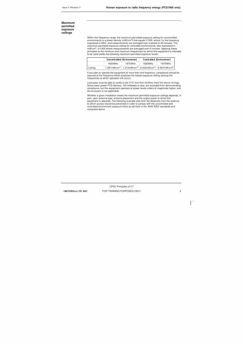
Within the frequency range, the maximum permitted exposure ceiling for uncontrolledenvironments is a power density (mW/cm2) that equals f/1500, where f is the frequencyexpressed in MHz, and measurements are averaged over a period of 30 minutes. Themaximum permitted exposure ceiling for controlled environments, also expressed inmW/cm2, is f/300 where measurements are averaged over 6 minutes. Applying theseprinciples to the minimum and maximum frequencies for which this equipment is intendedto be used yields the following maximum permitted exposure levels:
Uncontrolled Environment Controlled Environment
1930MHz 1970MHz 1930MHz 1970MHz
Ceiling 1.287mW/cm2 1.313mW/cm2 6.433mW/cm2 6.567mW/cm2
If you plan to operate the equipment at more than one frequency, compliance should beassured at the frequency which produces the lowest exposure ceiling (among thefrequencies at which operation will occur).
Licensees must be able to certify to the FCC that their facilities meet the above ceilings.Some lower power PCS devices, 100 milliwatts or less, are excluded from demonstratingcompliance, but this equipment operates at power levels orders of magnitude higher, andthe exclusion is not applicable.
Whether a given installation meets the maximum permitted exposure ceilings depends, inpart, upon antenna type, antenna placement and the output power to which thisequipment is adjusted. The following example sets forth the distances from the antennato which access should be prevented in order to comply with the uncontrolled andcontrolled environment exposure limits as set forth in the ANSI IEEE standards and
computed above.

8/4/2019 C7 Principles
http://slidepdf.com/reader/full/c7-principles 24/298
Issue 5 Revision 0Human exposure to radio frequency energy (PCS1900 only)
EMOTOROLA LTD. 2001
CP03: Principles of C7
FOR TRAINING PURPOSES ONLY10
Examplecalculation
For a base station with the following characteristics, what is the minimum distance fromthe antenna necessary to meet the requirements of an uncontrolled environment?
Transmit frequency 1930MHz
Base station cabinet output power, P +39.0dBm (8 watts)
Antenna feeder cable loss, CL 2.0dB
Antenna input power Pin P–CL = +39.0–2.0 = +37.0dB (5watts)
Antenna gain, G 16.4dBi (43.65)
Using the following relationship:
G+ 4 p r 2W
Pin
Where W is the maximum permissible power density in W/m2 and r is the safe distancefrom the antenna in metres, the desired distance can be calculated as follows:
r + GPin
4 pW + 43.65 5
4 p 12.87 + 1.16 m
where W = 12.87 W/m2 was obtained from table listed above and converting frommW/cm2 to W/m2.
The above result applies only in the direction of maximum radiation of theantenna. Actual installations may employ antennas that have defined radiationpatterns and gains that differ from the example set forth above. The distancescalculated can vary depending on the actual antenna pattern and gain.
NOTE
Power densitymeasurements
While installation calculations such as the above are useful and essential in planning anddesign, validation that the operating facility using this equipment actually complies willrequire making power density measurements. For information on measuring RF fields fordetermining compliance with ANSI IEEE C95.1-1991, see IEEE Recommended Practice for the Measure of Potentially Hazardous Electromagnetic Fields - RF and Microwave ,IEEE Std C95.3-1991. Copies of IEEE C95.1-1991 and IEEE C95.3-1991 may bepurchased from the Institute of Electrical and Electronics Engineers, Inc., Attn:Publication Sales, 445 Hoes Lane, P.O. Box 1331, Piscattaway, NJ 08855-1331,(800) 678-IEEE or from ANSI, (212) 642-4900. Persons responsible for installation of this
equipment are urged to consult these standards in determining whether a giveninstallation complies with the applicable limits.
Other equipment
Whether a given installation meets ANSI standards for human exposure to radiofrequency radiation may depend not only on this equipment but also on whether theenvironments being assessed are being affected by radio frequency fields from otherequipment, the effects of which may add to the level of exposure. Accordingly, the overallexposure may be affected by radio frequency generating facilities that exist at the timethe licensee’s equipment is being installed or even by equipment installed later.Therefore, the effects of any such facilities must be considered in site selection and indetermining whether a particular installation meets the FCC requirements.

8/4/2019 C7 Principles
http://slidepdf.com/reader/full/c7-principles 25/298
Issue 5 Revision 0 Beryllium health and safety precautions
EMOTOROLA LTD. 2001
CP03: Principles of C7
FOR TRAINING PURPOSES ONLY 11
Beryllium health and safety precautions
Introduction
Beryllium (Be), is a hard silver/white metal. It is stable in air, but burns brilliantly inOxygen.
With the exception of the naturally occurring Beryl ore (Beryllium Silicate), all Berylliumcompounds and Beryllium metal are potentially highly toxic.
Health issues
Beryllium Oxide is used within some components as an electrical insulator. Captive withinthe component it presents no health risk whatsoever. However, if the component shouldbe broken open and the Beryllium Oxide, which is in the form of dust, released, thereexists the potential for harm.
Inhalation
Inhalation of Beryllium Oxide can lead to a condition known as Berylliosis, the symptomsof Berylliosis are similar to Pneumonia and may be identified by all or any of thefollowing:
Mild poisoning causes fever, shortness of breath, and a cough that producesyellow/green sputum, or occasionally bloodstained sputum. Inflammation of the mucousmembranes of the nose, throat, and chest with discomfort, possibly pain, and difficultywith swallowing and breathing.
Severe poisoning causes chest pain and wheezing which may progress to severeshortness of breath due to congestion of the lungs. Incubation period for lung symptoms
is 2-20 days.
Exposure to moderately high concentrations of Beryllium in air may produce a veryserious condition of the lungs. The injured person may become blue, feverish with rapidbreathing and raised pulse rate. Recovery is usual but may take several months. Therehave been deaths in the acute stage.
Chronic response. This condition is more truly a general one although the lungs aremainly affected. There may be lesions in the kidneys and the skin. Certain featuressupport the view that the condition is allergic. There is no relationship between thedegree of exposure and the severity of response and there is usually a time lag of up to10 years between exposure and the onset of the illness. Both sexes are equallysusceptible. The onset of the illness is insidious but only a small number of exposedpersons develop this reaction.
First aid
Seek immediate medical assistance. The casualty should be removed immediately fromthe exposure area and placed in a fresh air environment with breathing supported withOxygen where required. Any contaminated clothing should be removed. The casualtyshould be kept warm and at rest until medical aid arrives.

8/4/2019 C7 Principles
http://slidepdf.com/reader/full/c7-principles 26/298
Issue 5 Revision 0Beryllium health and safety precautions
EMOTOROLA LTD. 2001
CP03: Principles of C7
FOR TRAINING PURPOSES ONLY12
Skin contact
Possible irritation and redness at the contact area. Persistent itching and blisterformations can occur which usually resolve on removal from exposure.
First aidWash area thoroughly with soap and water. If skin is broken seek immediate medicalassistance.
Eye contact
May cause severe irritation, redness and swelling of eyelid(s) and inflammation of themucous membranes of the eyes.
First aid
Flush eyes with running water for at least 15 minutes. Seek medical assistance as soon
as possible.
Handlingprocedures
Removal of components from printed circuit boards (PCBs) is to take place only atMotorola approved repair centres.
The removal station will be equipped with extraction equipment and all other protectiveequipment necessary for the safe removal of components containing Beryllium Oxide.
If during removal a component is accidently opened, the Beryllium Oxide dust is to bewetted into a paste and put into a container with a spatula or similar tool. The spatula/toolused to collect the paste is also to be placed in the container. The container is then to be
sealed and labelled. A suitable respirator is to be worn at all times during this operation.
Components which are successfully removed are to be placed in a separate bag, sealedand labelled.
Disposalmethods
Beryllium Oxide or components containing Beryllium Oxide are to be treated ashazardous waste. All components must be removed where possible from boards and putinto sealed bags labelled Beryllium Oxide components. These bags must be given to thesafety and environmental adviser for disposal.
Under no circumstances are boards or components containing Beryllium Oxide to be putinto the general waste skips or incinerated.
Product life cycleimplications
Motorola GSM and analogue equipment includes components containing Beryllium Oxide(identified in text as appropriate and indicated by warning labels on the equipment).These components require specific disposal measures as indicated in the preceding(Disposal methods) paragraph. Motorola will arrange for the disposal of all suchhazardous waste as part of its Total Customer Satisfaction philosophy and will arrangefor the most environmentally ‘friendly’ disposal available at that time.

8/4/2019 C7 Principles
http://slidepdf.com/reader/full/c7-principles 27/298
Issue 5 Revision 0 General cautions
EMOTOROLA LTD. 2001
CP03: Principles of C7
FOR TRAINING PURPOSES ONLY 13
General cautions
Introduction
Observe the following cautions during operation, installation and maintenance of theequipment described in the Motorola GSM manuals. Failure to comply with thesecautions or with specific cautions elsewhere in the Motorola GSM manuals may result indamage to the equipment. Motorola assumes no liability for the customer’s failure tocomply with these requirements.
Caution labels
Personnel working with or operating Motorola equipment must comply with any cautionlabels fitted to the equipment. Caution labels must not be removed, painted over orobscured in any way.
Specific cautions
Cautions particularly applicable to the equipment are positioned within the text of thismanual. These must be observed by all personnel at all times when working with theequipment, as must any other cautions given in text, on the illustrations and on theequipment.
Fibre optics
The bending radius of all fibre optic cables must not be less than 30 mm.
Static discharge
Motorola equipment contains CMOS devices that are vulnerable to static discharge.Although the damage caused by static discharge may not be immediately apparent,CMOS devices may be damaged in the long term due to static discharge caused bymishandling. Wear an approved earth strap when adjusting or handling digital boards.
See Devices sensitive to static for further information.

8/4/2019 C7 Principles
http://slidepdf.com/reader/full/c7-principles 28/298
Issue 5 Revision 0Devices sensitive to static
EMOTOROLA LTD. 2001
CP03: Principles of C7
FOR TRAINING PURPOSES ONLY14
Devices sensitive to static
Introduction
Certain metal oxide semiconductor (MOS) devices embody in their design a thin layer ofinsulation that is susceptible to damage from electrostatic charge. Such a charge appliedto the leads of the device could cause irreparable damage.
These charges can be built up on nylon overalls, by friction, by pushing the hands intohigh insulation packing material or by use of unearthed soldering irons.
MOS devices are normally despatched from the manufacturers with the leads shortedtogether, for example, by metal foil eyelets, wire strapping, or by inserting the leads intoconductive plastic foam. Provided the leads are shorted it is safe to handle the device.
Special handling
techniquesIn the event of one of these devices having to be replaced observe the followingprecautions when handling the replacement:
S Always wear an earth strap which must be connected to the electrostatic point(ESP) on the equipment.
S Leave the short circuit on the leads until the last moment. It may be necessary toreplace the conductive foam by a piece of wire to enable the device to be fitted.
S Do not wear outer clothing made of nylon or similar man made material. A cottonoverall is preferable.
S If possible work on an earthed metal surface. Wipe insulated plastic work surfaceswith an anti-static cloth before starting the operation.
S All metal tools should be used and when not in use they should be placed on anearthed surface.
S Take care when removing components connected to electrostatic sensitivedevices. These components may be providing protection to the device.
When mounted onto printed circuit boards (PCBs), MOS devices are normally lesssusceptible to electrostatic damage. However PCBs should be handled with care,preferably by their edges and not by their tracks and pins, they should be transferreddirectly from their packing to the equipment (or the other way around) and never leftexposed on the workbench.

8/4/2019 C7 Principles
http://slidepdf.com/reader/full/c7-principles 29/298
Issue 5 Revision 0 Motorola GSM manual set
EMOTOROLA LTD. 2001
CP03: Principles of C7
FOR TRAINING PURPOSES ONLY 15
Motorola GSM manual set
Introduction
The following manuals provide the information needed to operate, install and maintain theMotorola GSM equipment.
Generic manuals
The following are the generic manuals in the GSM manual set, these manuals arerelease dependent:
Categorynumber
Name Cataloguenumber
GSM-100-101 System Information: General 68P02901W01
GSM-100-201 Operating Information: GSM System Operation 68P02901W14GSM-100-311 Technical Description: OMC in a GSM System 68P02901W31
GSM-100-313 Technical Description: OMC Database Schema 68P02901W34
GSM-100-320 Technical Description: BSS Implementation 68P02901W36
GSM-100-321 Technical Description: BSS CommandReference
68P02901W23
GSM-100-403 Installation & Configuration: GSM SystemConfiguration
68P02901W17
GSM-100-423 Installation & Configuration: BSS Optimization 68P02901W43
GSM-100-501 Maintenance Information: Alarm Handling atthe OMC
68P02901W26
GSM-100-521 Maintenance Information: Device StateTransitions
68P02901W57
GSM-100-523 Maintenance Information: BSS FieldTroubleshooting
68P02901W51
GSM-100-503 Maintenance Information: GSM StatisticsApplication
68P02901W56
GSM-100-721 Software Release Notes: BSS/RXCDR 68P02901W72
Tandem OMC
The following Tandem OMC manuals are part of the GSM manual set for systemsdeploying Tandem S300 and 1475:
Categorynumber
Name Cataloguenumber
GSM-100-202 Operating Information: OMC SystemAdministration
68P02901W13
GSM-100-712 Software Release Notes: OMC System 68P02901W71

8/4/2019 C7 Principles
http://slidepdf.com/reader/full/c7-principles 30/298
Issue 5 Revision 0Motorola GSM manual set
EMOTOROLA LTD. 2001
CP03: Principles of C7
FOR TRAINING PURPOSES ONLY16
Scaleable OMC
The following Scaleable OMC manuals replace the equivalent Tandem OMC manuals inthe GSM manual set:
Categorynumber
Name Cataloguenumber
GSM-100-202 Operating Information: Scaleable OMC SystemAdministration
68P02901W19
GSM-100-413 Installation & Configuration: Scaleable OMCClean Install
68P02901W47
GSM-100-712 Software Release Notes: Scaleable OMCSystem
68P02901W74
Related manualsThe following are related Motorola GSM manuals:
Categorynumber
Name Cataloguenumber
GSM-001-103 System Information: BSS Equipment Planning 68P02900W21
GSM-002-103 System Information: DataGen 68P02900W22
GSM-005-103 System Information: Advance OperationalImpact
68P02900W25
GSM-008-403 Installation & Configuration: Expert Adviser 68P02900W36
Service manuals
The following are the service manuals in the GSM manual set, these manuals are notrelease dependent. The internal organization and makeup of service manual sets mayvary, they may consist of from one to four separate manuals, but they can all be orderedusing the overall catalogue number shown below:
Categorynumber
Name Cataloguenumber
GSM-100-020 Service Manual: BTS 68P02901W37
GSM-100-030 Service Manual: BSC/RXCDR 68P02901W38
GSM-105-020 Service Manual: M-Cell2 68P02901W75
GSM-106-020 Service Manual: M-Cell6 68P02901W85
GSM-201-020 Service Manual: M-Cellcity 68P02901W95
GSM-202-020 Service Manual: M-Cellaccess 68P02901W65
GSM-101-SERIES ExCell4 Documentation Set 68P02900W50
GSM-103-SERIES ExCell6 Documentation Set 68P02900W70
GSM-102-SERIES TopCell Documentation Set 68P02901W80
GSM-200-SERIES M-Cellmicro Documentation Set 68P02901W90

8/4/2019 C7 Principles
http://slidepdf.com/reader/full/c7-principles 31/298
Issue 5 Revision 0 Motorola GSM manual set
EMOTOROLA LTD. 2001
CP03: Principles of C7
FOR TRAINING PURPOSES ONLY 17
Category number
The category number is used to identify the type and level of a manual. For example,manuals with the category number GSM-100-2xx contain operating information.
Cataloguenumber
The Motorola 68P catalogue number is used to order manuals.
Orderingmanuals
All orders for Motorola manuals must be placed with your Motorola Local Office orRepresentative. Manuals are ordered using the catalogue number. Remember, specifythe manual issue required by quoting the correct suffix letter.

8/4/2019 C7 Principles
http://slidepdf.com/reader/full/c7-principles 32/298
Issue 5 Revision 0Motorola GSM manual set
EMOTOROLA LTD. 2001
CP03: Principles of C7
FOR TRAINING PURPOSES ONLY18

8/4/2019 C7 Principles
http://slidepdf.com/reader/full/c7-principles 33/298
EMOTOROLA LTD. 2001
CP03: Principles of C7
FOR TRAINING PURPOSES ONLY i
Chapter 1
Role of Signalling System
No 7 in GSM

8/4/2019 C7 Principles
http://slidepdf.com/reader/full/c7-principles 34/298
Issue 5 Revision 0
EMOTOROLA LTD. 2001
CP03: Principles of C7
FOR TRAINING PURPOSES ONLYii

8/4/2019 C7 Principles
http://slidepdf.com/reader/full/c7-principles 35/298
Issue 5 Revision 0
EMOTOROLA LTD. 2001
CP03: Principles of C7
FOR TRAINING PURPOSES ONLY iii
Chapter 1Role of Signalling SystemNo 7 in GSM i. . . . . . . . . . . . . . . . . . . . . . . . . . . . . . . . . . . . . . . . . . . . . . . . . . . . . . . .
Objectives 1–1. . . . . . . . . . . . . . . . . . . . . . . . . . . . . . . . . . . . . . . . . . . . . . . . . . . . . . . . . . . . . . . . .
SS7 in GSM 1–2. . . . . . . . . . . . . . . . . . . . . . . . . . . . . . . . . . . . . . . . . . . . . . . . . . . . . . . . . . . . . . .GSM Network Overview 1–2. . . . . . . . . . . . . . . . . . . . . . . . . . . . . . . . . . . . . . . . . . . . . . .
The Network Switching Subsystem 1–4. . . . . . . . . . . . . . . . . . . . . . . . . . . . . . . . . . . . . . . . . . . .
The Base Station System 1–6. . . . . . . . . . . . . . . . . . . . . . . . . . . . . . . . . . . . . . . . . . . . . . . . . . . .
Network Management Centre (NMC) 1–8. . . . . . . . . . . . . . . . . . . . . . . . . . . . . . . . . . . . . . . . . .
2Mbits PCM 1–10. . . . . . . . . . . . . . . . . . . . . . . . . . . . . . . . . . . . . . . . . . . . . . . . . . . . . . . . . . . . . . . .
SS7 Interfaces 1–12. . . . . . . . . . . . . . . . . . . . . . . . . . . . . . . . . . . . . . . . . . . . . . . . . . . . . . . . . . . . .
GSM Interface Names 1–14. . . . . . . . . . . . . . . . . . . . . . . . . . . . . . . . . . . . . . . . . . . . . . . . . . . . . . .
Interface Names 1–14. . . . . . . . . . . . . . . . . . . . . . . . . . . . . . . . . . . . . . . . . . . . . . . . . . . . . .

8/4/2019 C7 Principles
http://slidepdf.com/reader/full/c7-principles 36/298
Issue 5 Revision 0
EMOTOROLA LTD. 2001
CP03: Principles of C7
FOR TRAINING PURPOSES ONLYiv

8/4/2019 C7 Principles
http://slidepdf.com/reader/full/c7-principles 37/298
Issue 5 Revision 0 Objectives
EMOTOROLA LTD. 2001
CP03: Principles of C7
FOR TRAINING PURPOSES ONLY 1–1
Objectives
At the end of this chapter the student will be able to:
S Identify the two Subsystems and their components in GSM.
S Identify the components and interfaces of the GSM network and describe theirfunction.

8/4/2019 C7 Principles
http://slidepdf.com/reader/full/c7-principles 38/298
Issue 5 Revision 0SS7 in GSM
EMOTOROLA LTD. 2001
CP03: Principles of C7
FOR TRAINING PURPOSES ONLY1–2
SS7 in GSM
GSM network components
GSM NetworkOverview
The diagram opposite shows a simplified GSM network. Each network component isillustrated only once. However, many of the components will occur several timesthroughout a network.
Each network component is designed to communicate over an interface specified by theGSM standards. This provides flexibility and enables a network provider to utilizesystem components from different manufacturers. For example Motorola Base StationSystem (BSS) equipment may be coupled with an Ericsson Network Switching System.
The principle component groups of a GSM network are:
The Mobile Station (MS)
This consists of the mobile telephone, fax machine etc. This is the part of the networkthat the subscriber will see.
The Base Station System (BSS)
This BSS is the part of the network that provides the radio interconnection from the MSto the land-based switching equipment.
The Network Switching System (NSS)
The NSS consists of the Mobile services Switching Centre (MSC) and its associated
system-control databases and processors together with the required interfaces. This isthe part that provides for interconnection between the GSM network and the PublicSwitched Telephone Network (PSTN).
The Operations and Maintenance Centre (OMC)
This enables the network provider to configure and maintain the network from a centrallocation.

8/4/2019 C7 Principles
http://slidepdf.com/reader/full/c7-principles 39/298
Issue 5 Revision 0 SS7 in GSM
EMOTOROLA LTD. 2001
CP03: Principles of C7
FOR TRAINING PURPOSES ONLY 1–3
GSM Network Components
CP03_Ch1_01
NMC
OMC
Operations and
Maintenance SystemNetwork Switching System
Base Station System
Interface/Connection
Mobile Station
PSTN
VLR HLR
AUC
EIR
MSC
IWFEC
BTS
BSC
ME
SIM
XCDR

8/4/2019 C7 Principles
http://slidepdf.com/reader/full/c7-principles 40/298
Issue 5 Revision 0The Network Switching Subsystem
EMOTOROLA LTD. 2001
CP03: Principles of C7
FOR TRAINING PURPOSES ONLY1–4
The Network Switching Subsystem
Network Switching System
The Network Switching System includes the main switching functions of the GSMnetwork. It also contains the databases required for subscriber data and mobilitymanagement. Its main function is to manage communications between the GSMnetwork and other telecommunications networks.
The components of the Network Switching System are listed below:
S Mobile Services Switching Centre (MSC)
S Home Location Register (HLR)
S Visitor Location Register (VLR)
S Equipment Identity Register (EIR)
S Authentication Centre (AUC)
S InterWorking Function (IWF)
S Echo Canceller (EC)
In addition to the more traditional elements of a cellular telephone system, GSM hasLocation Register network entities. These entities are the Home Location Register(HLR), Visitor Location Register (VLR), and the Equipment Identity Register (EIR). Thelocation registers are database-oriented processing nodes, which address the problemsof managing subscriber data and keeping track of a MS’s location as it roams around thenetwork.
Functionally, the Interworking Function and the Echo Cancellers may be considered asparts of the MSC, since their activities are inextricably linked with those of the switch as itconnects speech and data calls to and from the MSs.

8/4/2019 C7 Principles
http://slidepdf.com/reader/full/c7-principles 41/298
Issue 5 Revision 0 The Network Switching Subsystem
EMOTOROLA LTD. 2001
CP03: Principles of C7
FOR TRAINING PURPOSES ONLY 1–5
Networking Switching System
CP03_Ch1_02
VLR
EC IWF
MSC
HLR
AUC
EIR
Network Switching System
VLR
EC IWF
MSC
HLR
AUC
EIR
Network Switching System
PSTN
PSTN
PSTN
Operationsand
Maintenance System
Operationsand
Maintenance System
Operationsand
Maintenance System
BSS
BSS
BSS

8/4/2019 C7 Principles
http://slidepdf.com/reader/full/c7-principles 42/298
Issue 5 Revision 0The Base Station System
EMOTOROLA LTD. 2001
CP03: Principles of C7
FOR TRAINING PURPOSES ONLY1–6
The Base Station System
The GSM Base Station System is the equipment located at a cell site. It comprises acombination of digital and RF equipment. The BSS provides the link between the MobileStation (MS) and the Mobile services Switching Centre (MSC).
The BSS communicates with the MS over the digital air interface and with the MSC via 2Mbit/s links.
The BSS consists of three major hardware components:
The Base Transceiver Station (BTS)
The BTS contains the RF components that provide the air interface for a particular cell.This is the part of the GSM network that communicates with the MS. The antenna isincluded as part of the BTS.
The Base Station Controller (BSC)
The BSC as its name implies provides the control for the BSS. The BSC communicatesdirectly with the MSC. The BSC may control single or multiple BTSs.
The Transcoder (XCDR)
The transcoder is used to compact the signals from the MS so that they are moreefficiently sent over the terrestrial interfaces. Although the transcoder is considered to bea part of the BSS, it is very often located closer to the MSC.
The transcoder is used to reduce the rate at which the traffic (voice/data) is transmittedover the air interface. Although the transcoder is part of the BSS, it is often foundphysically closer to the NSS to allow more efficient use of the terrestrial links.

8/4/2019 C7 Principles
http://slidepdf.com/reader/full/c7-principles 43/298
Issue 5 Revision 0 The Base Station System
EMOTOROLA LTD. 2001
CP03: Principles of C7
FOR TRAINING PURPOSES ONLY 1–7
Base Station System
CP03_Ch1_03
BSC
BSS
BTS
XCDR
BTS
BTSBTS

8/4/2019 C7 Principles
http://slidepdf.com/reader/full/c7-principles 44/298
Issue 5 Revision 0Network Management Centre (NMC)
EMOTOROLA LTD. 2001
CP03: Principles of C7
FOR TRAINING PURPOSES ONLY1–8
Network Management Centre (NMC)
The NMC offers the ability to provide hierarchical regionalized network management of acomplete GSM system.
It is responsible for operations and maintenance at the network level, supported by theOMCs which are responsible for regional network management.
The NMC is therefore a single logical facility at the top of the network managementhierarchy.
The NMC has a high level view of the network, as a series of network nodes andinterconnecting communications facilities.
The OMC, on the other hand, is used to filter information from the network equipment forforwarding to the NMC, thus allowing it to focus on issues requiring nationalco-ordination. The NMC can also co-ordinate issues regarding interconnection to othernetworks, for example the Public Switched Telephone Network (PSTN).
The NMC can take regional responsibility when an OMC is not manned, with the OMC
acting as a transit point between the NMC and the network equipment. The NMCprovides operators with functions equivalent to those available at the OMC.
Functionality of the NMC
S Monitors node on the network.
S Monitors GSM Network Element Statistics.
S Monitors OMC regions and provides information to OMC staff.
S Passes on statistical information from one OMC region to another to improveproblem strategies.

8/4/2019 C7 Principles
http://slidepdf.com/reader/full/c7-principles 45/298
Issue 5 Revision 0 Network Management Centre (NMC)
EMOTOROLA LTD. 2001
CP03: Principles of C7
FOR TRAINING PURPOSES ONLY 1–9
Network Management Centre
CP03_Ch1_04
NMC
OMC
OMC
OMC
NETWORK
REGION 1
REGION 2 REGION 3
Q3 PROTOCOL(GSM 12 SERIES)

8/4/2019 C7 Principles
http://slidepdf.com/reader/full/c7-principles 46/298
Issue 5 Revision 02Mbits PCM
EMOTOROLA LTD. 2001
CP03: Principles of C7
FOR TRAINING PURPOSES ONLY1–10
2Mbits PCM
2 Mbit/s Trunk 32-channel PCM
This diagram opposite shows the logical GSM system with the 2 Mbit/s interfaceshighlighted.
The interfaces carry traffic from the PSTN to the MSC, between MSCs, from an MSC toa BSC and from a BSC to remotely sited BTSs.
These links are also used between the MSC and IWF.
Each 2.048 Mbit/s link provides thirty-two 64 kbit/s channels available to carry speech,data, or control information. The control information may contain C7, LAPD or X.25formatted information.
These 2 Mbit/s links commonly act as the physical bearer for the interfaces usedbetween the GSM system entities.

8/4/2019 C7 Principles
http://slidepdf.com/reader/full/c7-principles 47/298
Issue 5 Revision 0 2Mbits PCM
EMOTOROLA LTD. 2001
CP03: Principles of C7
FOR TRAINING PURPOSES ONLY 1–11
2Mbit trunks
CP03_Ch1_05
NMC
OMC
VLR
MSC
ECIWFXC
XC
VLR
EC IWF XC
MSC
HLR
AUC
EIR
PSTN
BTS BSC
CO–LOCATED ENTITIES
BSS
BTS
BTS
BTS
BTS
BTS
BTS
BSC
BTS BTS BTS
MS
MS
MS
VLR

8/4/2019 C7 Principles
http://slidepdf.com/reader/full/c7-principles 48/298
Issue 5 Revision 0SS7 Interfaces
EMOTOROLA LTD. 2001
CP03: Principles of C7
FOR TRAINING PURPOSES ONLY1–12
SS7 Interfaces
The term C7 and SS7 are describing the same function, they both describe the signallingfunction of the network, either term may be used
ITU-TS Signalling System #7
The diagram opposite illustrates the use of C7 in the GSM system; carrying signallingand control information between most major entities, and to and from the PSTN.
The following message protocols, which are part of C7, are used to communicatebetween the different GSM network entities:
Interfacing the PSTN, the MSC performs call-signalling functions using the TelephoneUser Part (TUP), or interfacing ISDN, the ISDN User Part (ISUP).
Between the MSC and the BSC, the Base Station System Management Application Part(BSSMAP) is used.
The Direct Transfer Application Part (DTAP) is used to send messages between theMSC and the mobile (MS).
MAP is used between the MSC and the VLR, EIR, and HLR.
Acronyms:
BSSAP Base Station System Application Part
BSSMAP Base Station System Management Application Part
DTAP Direct Transfer Application Part
ISUP ISDN User Part
MAP Mobile Application Part
SCCP Signalling connection Control Part
TUP Telephone User Part
TCAP Transaction Capabilities Application Part

8/4/2019 C7 Principles
http://slidepdf.com/reader/full/c7-principles 49/298
Issue 5 Revision 0 SS7 Interfaces
EMOTOROLA LTD. 2001
CP03: Principles of C7
FOR TRAINING PURPOSES ONLY 1–13
C7 Interfaces
CP03_Ch1_06
MAP
NMC
OMC
VLR
MSC
ECIWFXC
XC
VLR
ECIWF
XC
MSC
HLR
AUC
EIR
PSTN
BTS BSC
BSS
BTS
BTS
BTS
BTS
BTS
BTS
BSC
BTS BTS BTS
MS
MS
MS
VLR
BSSMAP TUP
BSSAP

8/4/2019 C7 Principles
http://slidepdf.com/reader/full/c7-principles 50/298
Issue 5 Revision 0GSM Interface Names
EMOTOROLA LTD. 2001
CP03: Principles of C7
FOR TRAINING PURPOSES ONLY1–14
GSM Interface Names
Interface Names
Each interface specified within the GSM system has a name associated with it. Thediagram opposite illustrates the names of all the interfaces specified by GSM.
Air-interface MS–BTS
A-bis(Mo-bis) BTS–BSC
A-interface BSS–MSC
B-Interface MSC–VLR
C-interface MSC–HLR
D-interface HLR–VLR
E-interface inter–MSC
F-interface MSC–EIR
G-interface VLR–VLR
R-interface MS–DTE (Data Terminating Equipment)

8/4/2019 C7 Principles
http://slidepdf.com/reader/full/c7-principles 51/298
Issue 5 Revision 0 GSM Interface Names
EMOTOROLA LTD. 2001
CP03: Principles of C7
FOR TRAINING PURPOSES ONLY 1–15
GSM interface names
CP03_Ch1_07
NMC
OMC
VLR
MSC
ECIWFXC
XC
VLR
EC IWF XC
MSC
HLR
AUC
EIR
PSTN
BTS BSC
CO–LOCATED ENTITIES
BSS
BTS
BTS
BTS
BTS
BTS
BTS
BSC
BTS BTS BTS
MS
MS
MS
VLR
A
E
Abis
Um
G
B
D
BC
H
F

8/4/2019 C7 Principles
http://slidepdf.com/reader/full/c7-principles 52/298
Issue 5 Revision 0GSM Interface Names
EMOTOROLA LTD. 2001
CP03: Principles of C7
FOR TRAINING PURPOSES ONLY1–16

8/4/2019 C7 Principles
http://slidepdf.com/reader/full/c7-principles 53/298
EMOTOROLA LTD. 2001
CP03: Principles of C7
FOR TRAINING PURPOSES ONLY i
Chapter 2
The SS7 Network

8/4/2019 C7 Principles
http://slidepdf.com/reader/full/c7-principles 54/298
Issue 5 Revision 0
EMOTOROLA LTD. 2001
CP03: Principles of C7
FOR TRAINING PURPOSES ONLYii

8/4/2019 C7 Principles
http://slidepdf.com/reader/full/c7-principles 55/298
Issue 5 Revision 0
EMOTOROLA LTD. 2001
CP03: Principles of C7
FOR TRAINING PURPOSES ONLY iii
Chapter 2The SS7 Network i. . . . . . . . . . . . . . . . . . . . . . . . . . . . . . . . . . . . . . . . . . . . . . . . . . .
Objectives 2–1. . . . . . . . . . . . . . . . . . . . . . . . . . . . . . . . . . . . . . . . . . . . . . . . . . . . . . . . . . . . . . . . .
Main Requirements of SS7 2–2. . . . . . . . . . . . . . . . . . . . . . . . . . . . . . . . . . . . . . . . . . . . . . . . . .
Signalling Elements in a Network 2–4. . . . . . . . . . . . . . . . . . . . . . . . . . . . . . . . . . . . . . . . . . . . .
Signalling Point/Signalling Transfer Point 2–6. . . . . . . . . . . . . . . . . . . . . . . . . . . . . . . . . . . . . . .
Signalling Point Code 2–8. . . . . . . . . . . . . . . . . . . . . . . . . . . . . . . . . . . . . . . . . . . . . . . . . . . . . . .
Format of Signalling Point Code 2–10. . . . . . . . . . . . . . . . . . . . . . . . . . . . . . . . . . . . . . . . . . . . . .
Numbering of International Signalling Points 2–10. . . . . . . . . . . . . . . . . . . . . . . . . . . . . .
Signalling Link and Link Sets 2–12. . . . . . . . . . . . . . . . . . . . . . . . . . . . . . . . . . . . . . . . . . . . . . . . .
SS7 Signalling Link Types 2–12. . . . . . . . . . . . . . . . . . . . . . . . . . . . . . . . . . . . . . . . . . . . . .
Signalling Route and Route Set 2–14. . . . . . . . . . . . . . . . . . . . . . . . . . . . . . . . . . . . . . . . . . . . . . .
Message Routing across a network 2–16. . . . . . . . . . . . . . . . . . . . . . . . . . . . . . . . . . . . . . . . . . .
Signalling Methods 2–18. . . . . . . . . . . . . . . . . . . . . . . . . . . . . . . . . . . . . . . . . . . . . . . . . . . . . . . . . .E1 PCM 2–20. . . . . . . . . . . . . . . . . . . . . . . . . . . . . . . . . . . . . . . . . . . . . . . . . . . . . . . . . . . . . . . . . . .
SCP Database 2–22. . . . . . . . . . . . . . . . . . . . . . . . . . . . . . . . . . . . . . . . . . . . . . . . . . . . . . . . . . . . .
Service Switching Point (SSP) 2–22. . . . . . . . . . . . . . . . . . . . . . . . . . . . . . . . . . . . . . . . . .
Service Control Point (SCP) 2–22. . . . . . . . . . . . . . . . . . . . . . . . . . . . . . . . . . . . . . . . . . . .
The SS7 Network 2–24. . . . . . . . . . . . . . . . . . . . . . . . . . . . . . . . . . . . . . . . . . . . . . . . . . . . . . . . . . .

8/4/2019 C7 Principles
http://slidepdf.com/reader/full/c7-principles 56/298
Issue 5 Revision 0
EMOTOROLA LTD. 2001
CP03: Principles of C7
FOR TRAINING PURPOSES ONLYiv

8/4/2019 C7 Principles
http://slidepdf.com/reader/full/c7-principles 57/298
Issue 5 Revision 0 Objectives
EMOTOROLA LTD. 2001
CP03: Principles of C7
FOR TRAINING PURPOSES ONLY 2–1
Objectives
At the end of this chapter you will be able to:
S Identify the different functions that make up a signalling network.
S Understand the functionality within an SS7 network.

8/4/2019 C7 Principles
http://slidepdf.com/reader/full/c7-principles 58/298
Issue 5 Revision 0Main Requirements of SS7
EMOTOROLA LTD. 2001
CP03: Principles of C7
FOR TRAINING PURPOSES ONLY2–2
Main Requirements of SS7
There are two main requirements of the signalling system.
S All calls must be set-up, monitored and broken down in a correct manner.
S The signalling system must be able to support all non-circuit applications such asdatabase enquires and supplementary services.
The SS7 network and protocol are used for:
S Basic call set-up, management, and tear down.
S Wireless services such as personal communications services (PCS), wirelessroaming, and mobile subscriber authentication.
S Local number portability (LNP).
S Toll-free (800/888) and toll (900) wire line services.
S Enhanced call features such as call forwarding, calling party name/number display,
and three-way calling.
S Efficient and secure worldwide telecommunications.
Network management information must also be carried across the network. This enablesthe network to maintain itself during failures and then recover from them.
The network also needs to deal with load sharing and re-routing this is also achievedthrough the use of SS7
When looking at any signalling requirements within a telephone network it is important tounderstand that all voice calls breakdown into two separate components, the voicecomponent and the signalling component. All other calls are just seen by the network asdata that is signalling

8/4/2019 C7 Principles
http://slidepdf.com/reader/full/c7-principles 59/298
Issue 5 Revision 0 Main Requirements of SS7
EMOTOROLA LTD. 2001
CP03: Principles of C7
FOR TRAINING PURPOSES ONLY 2–3
Main Requirements of SS7
CP03_Ch2_01
Circuit related applications concerned with the connection and
disconnection of telephone calls
Non circuit related applications which support the circuit relatedapplications
To achieve call processing the different components in the network mustbe able to interact with each other.
A call is made up of two components:
– The voice/data component.
– The signalling component.

8/4/2019 C7 Principles
http://slidepdf.com/reader/full/c7-principles 60/298
Issue 5 Revision 0Signalling Elements in a Network
EMOTOROLA LTD. 2001
CP03: Principles of C7
FOR TRAINING PURPOSES ONLY2–4
Signalling Elements in a Network
SP/STP The basic blocks in the network
SPC An address of a single unit in the network
Signalling link The physical connection
Link set More than one physical connection between the same two points
Route The logical connection between two points in a network
Route set More than one logical connection between the same two points
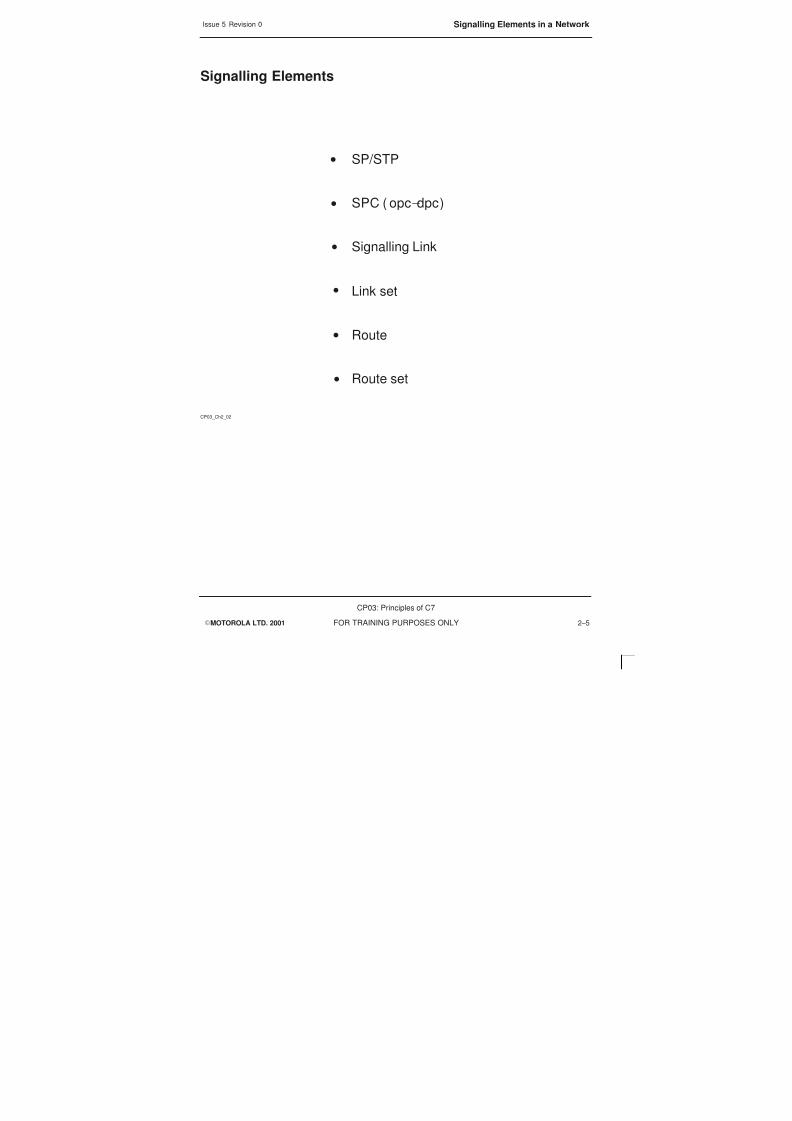
8/4/2019 C7 Principles
http://slidepdf.com/reader/full/c7-principles 61/298
Issue 5 Revision 0 Signalling Elements in a Network
EMOTOROLA LTD. 2001
CP03: Principles of C7
FOR TRAINING PURPOSES ONLY 2–5
Signalling Elements
CP03_Ch2_02
SP/STP
SPC ( opc–dpc)
Signalling Link
Link set
Route
Route set
S
S
S
S
S
S

8/4/2019 C7 Principles
http://slidepdf.com/reader/full/c7-principles 62/298
Issue 5 Revision 0Signalling Point/Signalling Transfer Point
EMOTOROLA LTD. 2001
CP03: Principles of C7
FOR TRAINING PURPOSES ONLY2–6
Signalling Point/Signalling Transfer Point
Signalling Point (SP)
A Signalling Point is any node in the network that is able to handle signalling messages.These signalling messages can either be generated or received
Signalling transfer Point (STP)
A Signalling Transfer Point is able to receive a message on one signalling link and thentransfer that message to another link, without processing the contents of the message.
STP is able to transfer in three dimensions, national, regional and international
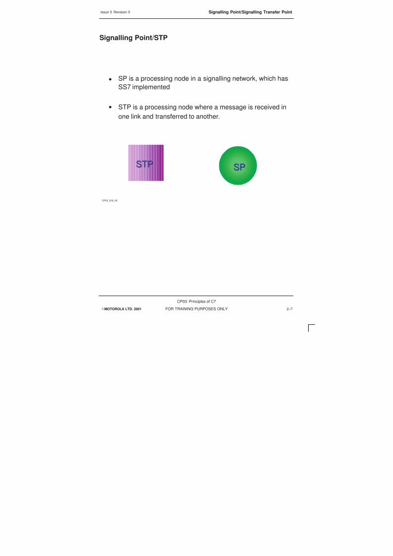
8/4/2019 C7 Principles
http://slidepdf.com/reader/full/c7-principles 63/298
Issue 5 Revision 0 Signalling Point/Signalling Transfer Point
EMOTOROLA LTD. 2001
CP03: Principles of C7
FOR TRAINING PURPOSES ONLY 2–7
Signalling Point/STP
CP03_Ch2_03
SP is a processing node in a signalling network, which has
SS7 implemented
STP is a processing node where a message is received in
one link and transferred to another.
SPSPSTPSTP
S
S

8/4/2019 C7 Principles
http://slidepdf.com/reader/full/c7-principles 64/298
Issue 5 Revision 0Signalling Point Code
EMOTOROLA LTD. 2001
CP03: Principles of C7
FOR TRAINING PURPOSES ONLY2–8
Signalling Point Code
Signalling Point Code (SPC)
In the SS7 network all signalling points (SP) need to be identified in order to allow forcommunication between each other. All Signalling Points are identified by a unique codeknown as the Signalling Point Code (SPC)
The Signalling Point at which the signalling message is generated, or is the source userpart is known as the Originating Point Code (OPC)
The Signalling Point to which the signalling message is destined, or is the receiving userpart is known as the Destination Point Code (DPC)
In order to allow for multiplayer signalling there must be a method that allows forcommunication between different networks. It is the Network Indicator (NI) that must bedefined for this.
SP = NI – SPC
The SPC is normally 14 bits long in the binary form. This can be translated to either hexor various national presentations

8/4/2019 C7 Principles
http://slidepdf.com/reader/full/c7-principles 65/298
Issue 5 Revision 0 Signalling Point Code
EMOTOROLA LTD. 2001
CP03: Principles of C7
FOR TRAINING PURPOSES ONLY 2–9
Signalling Point Code
CP03_Ch2_04
All signalling points in a SS7 network are identified by a unique code
known as a Signalling Point Code SPC
There are two components to a SPC
SP = NI –SPC
S
S

8/4/2019 C7 Principles
http://slidepdf.com/reader/full/c7-principles 66/298

8/4/2019 C7 Principles
http://slidepdf.com/reader/full/c7-principles 67/298
8/4/2019 C7 Principles
http://slidepdf.com/reader/full/c7-principles 68/298
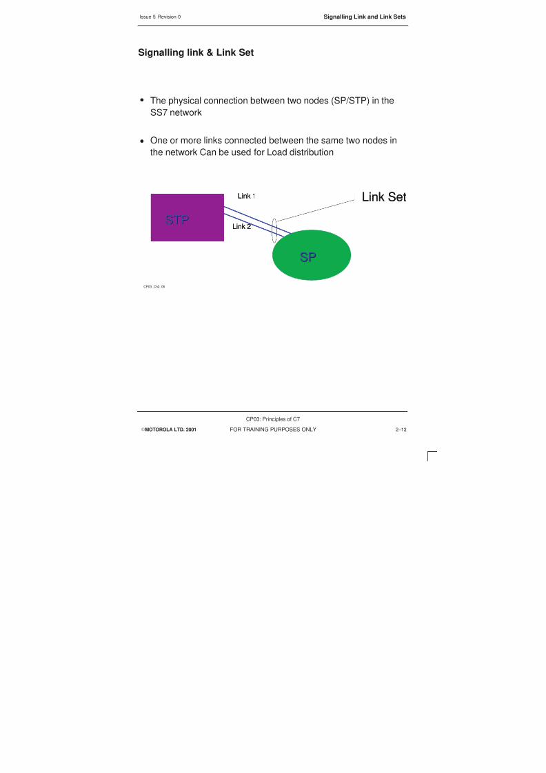
8/4/2019 C7 Principles
http://slidepdf.com/reader/full/c7-principles 69/298
Issue 5 Revision 0 Signalling Link and Link Sets
EMOTOROLA LTD. 2001
CP03: Principles of C7
FOR TRAINING PURPOSES ONLY 2–13
Signalling link & Link Set
CP03_Ch2_06
The physical connection between two nodes (SP/STP) in the
SS7 network
One or more links connected between the same two nodes in
the network Can be used for Load distribution
Link 2
SPSP
STPSTP
Link 1 Link Set
Link 2
SPSP
STPSTP
Link 1 Link Set
S
S

8/4/2019 C7 Principles
http://slidepdf.com/reader/full/c7-principles 70/298
Issue 5 Revision 0Signalling Route and Route Set
EMOTOROLA LTD. 2001
CP03: Principles of C7
FOR TRAINING PURPOSES ONLY2–14
Signalling Route and Route Set
A signalling route is the pre-determined path, consisting of a succession of STPs andinterconnecting SLs that take a message through the network between the originatingpoint to the destination point.
Each route carries traffic to only one destination, the route may be direct or over severalSTPs, the SLs in a route may belong to several routes and as such carry traffic toseveral destinations
SLs and data in STPs combine to form a signalling route.
All the signalling routes that may be used between an originating point and a destinationpoint are known as a Signalling Route Set.

8/4/2019 C7 Principles
http://slidepdf.com/reader/full/c7-principles 71/298
Issue 5 Revision 0 Signalling Route and Route Set
EMOTOROLA LTD. 2001
CP03: Principles of C7
FOR TRAINING PURPOSES ONLY 2–15
Signalling Route and Route Set
CP03_Ch2_07
A signalling route is a predetermined path that takes themessage through the signalling network
A route set is one or more routes linked together
SPSPSPSP
STPSTP
Link Set
STPSTP
Link Set
STPSTP
Link Set
STPSTP
Link Set
STPSTP
Link Set
Signalling route
S
S

8/4/2019 C7 Principles
http://slidepdf.com/reader/full/c7-principles 72/298

8/4/2019 C7 Principles
http://slidepdf.com/reader/full/c7-principles 73/298
Issue 5 Revision 0 Message Routing across a network
EMOTOROLA LTD. 2001
CP03: Principles of C7
FOR TRAINING PURPOSES ONLY 2–17
Message Routing
CP03_Ch2_08
Link SetOPC 2 –2–2
SPSP
STPSTP
STPSTP
Link Set
STPSTP
Link Set
signallinglink
Link Set
OPC 1 –1–1
STPSTP
STPSTP
SPSP

8/4/2019 C7 Principles
http://slidepdf.com/reader/full/c7-principles 74/298

8/4/2019 C7 Principles
http://slidepdf.com/reader/full/c7-principles 75/298
Issue 5 Revision 0 Signalling Methods
EMOTOROLA LTD. 2001
CP03: Principles of C7
FOR TRAINING PURPOSES ONLY 2–19
Signalling Methods
CP03_Ch2_09
Voice and Signalling Channel
Signalling Channel
Voice Channels
CAS
CCS

8/4/2019 C7 Principles
http://slidepdf.com/reader/full/c7-principles 76/298
Issue 5 Revision 0E1 PCM
EMOTOROLA LTD. 2001
CP03: Principles of C7
FOR TRAINING PURPOSES ONLY2–20
E1 PCM
An E1 or 2.048Mbit/s PCM frame is made up of 32 eight-bit timeslots, numbered from 0to 31. Timeslot (T/S) 0 is always used for sync, this enables incoming slots to be read atthe correct time, timeslot 16 is normally used for signalling – this is not mandatory but it
is widely accepted as the norm.
Sampling of the analogue signal is done at 8000 times per second. Each frame consistsof 8 bits from each timeslot. So, each timeslot is 88000=64,000 bits per second 64Kbit/sec
When referred to, the term E1 indicates both transmission and reception components.

8/4/2019 C7 Principles
http://slidepdf.com/reader/full/c7-principles 77/298
Issue 5 Revision 0 E1 PCM
EMOTOROLA LTD. 2001
CP03: Principles of C7
FOR TRAINING PURPOSES ONLY 2–21
E1 PCM
CP03_Ch2_10
VOICE
32 timeslots @64 kb/s
0 16 31
What is an E1 PCM?
VOICE
SYNC SIG
8/4/2019 C7 Principles
http://slidepdf.com/reader/full/c7-principles 78/298
Issue 5 Revision 0SCP Database
EMOTOROLA LTD. 2001
CP03: Principles of C7
FOR TRAINING PURPOSES ONLY2–22
SCP Database
The terms SSP and SCP are used in the Intelligent Network (IN), they explain theoperation of database enquiries.
ServiceSwitching Point(SSP)
SSPs are switches that originate, terminate, or tandem calls. An SSP sends signallingmessages to other SSPs to set-up, manage, and release voice circuits required tocomplete a call. An SSP may also send a query message to a centralized database (anSCP) to determine how to route a call (e.g., a toll-free 1-800/888 call in North America).
Service ControlPoint (SCP)
An SCP sends a response to the originating SSP containing the routing number(s)associated with the dialled number. An alternate routing number may be used by theSSP if the primary number is busy or the call is unanswered within a specified time.Actual call features vary from network to network and from service to service.
Databases may be either physically internal or external to the SCP, but must beconsidered a separate device. There are several types of database, which include:
S Call Management Service Database (CMSDB)
S Number Portability (NP)
S Line Information Database (LIDB)
S Home Location Register (HLR)
S Visitor Location Register (VLR)
Registers act as an interface to the telephone company database, and translate nongeographical numbers from a database to provide information for calling card, subscriberservices, fraud protection and intelligent networks

8/4/2019 C7 Principles
http://slidepdf.com/reader/full/c7-principles 79/298
Issue 5 Revision 0 SCP Database
EMOTOROLA LTD. 2001
CP03: Principles of C7
FOR TRAINING PURPOSES ONLY 2–23
Network Databases
CP03_Ch2_11
SCP
SSP
SSP
SCP
SS7 LINKS
SCP
SCP
SSP
SSP
SCP
SCP
SS7 LINKS

8/4/2019 C7 Principles
http://slidepdf.com/reader/full/c7-principles 80/298
Issue 5 Revision 0The SS7 Network
EMOTOROLA LTD. 2001
CP03: Principles of C7
FOR TRAINING PURPOSES ONLY2–24
The SS7 Network
The SS7 network can be divided into two parts, Voice and Signalling. As alreadymentioned they do need to follow the same physical path, and the two components arerequired to achieve a completed call.
In the network the signalling can also be broken into separate parts, one for the control ofthe voice and a second that is involved with database access. The database queries areclose to register signalling, however they can also be from many User Parts (UP) orapplication parts (AP).
The first parts of the network that will be used are the SPs and the SSPs these willestablish the validity of the call and also prepare the voice circuit, behind these parts theother components in the network the STPs and the SSPs will be used in the set up, or toanswer database queries and send reponses.

8/4/2019 C7 Principles
http://slidepdf.com/reader/full/c7-principles 81/298
Issue 5 Revision 0 The SS7 Network
EMOTOROLA LTD. 2001
CP03: Principles of C7
FOR TRAINING PURPOSES ONLY 2–25
The SS7 Network
CP03_Ch2_12
STP
STP
SCP
SCP
SS7 Links
STP
STP
SCP
SCP
SCP
SCP
SS7 LinksVOICE CIRCUITS
SP
SP
SSP
SSP
VOICE CIRCUITS
SP
SP
SSP
SSP

8/4/2019 C7 Principles
http://slidepdf.com/reader/full/c7-principles 82/298
Issue 5 Revision 0The SS7 Network
EMOTOROLA LTD. 2001
CP03: Principles of C7
FOR TRAINING PURPOSES ONLY2–26

8/4/2019 C7 Principles
http://slidepdf.com/reader/full/c7-principles 83/298
EMOTOROLA LTD. 2001
CP03: Principles of C7
FOR TRAINING PURPOSES ONLY i
Chapter 3
SS7 4 Level Model

8/4/2019 C7 Principles
http://slidepdf.com/reader/full/c7-principles 84/298
Issue 5 Revision 0
EMOTOROLA LTD. 2001
CP03: Principles of C7
FOR TRAINING PURPOSES ONLYii

8/4/2019 C7 Principles
http://slidepdf.com/reader/full/c7-principles 85/298
Issue 5 Revision 0
EMOTOROLA LTD. 2001
CP03: Principles of C7
FOR TRAINING PURPOSES ONLY iii
Chapter 3SS7 4 Level Model i. . . . . . . . . . . . . . . . . . . . . . . . . . . . . . . . . . . . . . . . . . . . . . . . . .
Objectives 3–1. . . . . . . . . . . . . . . . . . . . . . . . . . . . . . . . . . . . . . . . . . . . . . . . . . . . . . . . . . . . . . . . .
Protocols 3–2. . . . . . . . . . . . . . . . . . . . . . . . . . . . . . . . . . . . . . . . . . . . . . . . . . . . . . . . . . . . . . . . . .
Protocol Layers of the OSI 7 Model 3–4. . . . . . . . . . . . . . . . . . . . . . . . . . . . . . . . . . . . . . . . . . .
Protocol Comparison of OSI to SS7 3–6. . . . . . . . . . . . . . . . . . . . . . . . . . . . . . . . . . . . . . . . . . .
SS7 to OSI Overview 3–8. . . . . . . . . . . . . . . . . . . . . . . . . . . . . . . . . . . . . . . . . . . . . . . . . . . . . . .
MTP Layer 1 3–10. . . . . . . . . . . . . . . . . . . . . . . . . . . . . . . . . . . . . . . . . . . . . . . . . . . . . . . . . . . . . . .
MTP Layer 2 3–12. . . . . . . . . . . . . . . . . . . . . . . . . . . . . . . . . . . . . . . . . . . . . . . . . . . . . . . . . . . . . . .
MTP Layer 2 Functionality 3–14. . . . . . . . . . . . . . . . . . . . . . . . . . . . . . . . . . . . . . . . . . . . . . . . . . .
MTP Layer 3 3–16. . . . . . . . . . . . . . . . . . . . . . . . . . . . . . . . . . . . . . . . . . . . . . . . . . . . . . . . . . . . . . .
MTP Layer 3 Functionality 3–18. . . . . . . . . . . . . . . . . . . . . . . . . . . . . . . . . . . . . . . . . . . . . . . . . . .
Traffic Handling 3–18. . . . . . . . . . . . . . . . . . . . . . . . . . . . . . . . . . . . . . . . . . . . . . . . . . . . . . .
Signalling Network Management 3–18. . . . . . . . . . . . . . . . . . . . . . . . . . . . . . . . . . . . . . . .MTP Functionality 3–20. . . . . . . . . . . . . . . . . . . . . . . . . . . . . . . . . . . . . . . . . . . . . . . . . . . . . . . . . .
Message discrimination 3–20. . . . . . . . . . . . . . . . . . . . . . . . . . . . . . . . . . . . . . . . . . . . . . . .
Message Transfer Part 3–22. . . . . . . . . . . . . . . . . . . . . . . . . . . . . . . . . . . . . . . . . . . . . . . . . . . . . .
SS7 layer 4 3–24. . . . . . . . . . . . . . . . . . . . . . . . . . . . . . . . . . . . . . . . . . . . . . . . . . . . . . . . . . . . . . . .
SS7 to OSI layers 3–26. . . . . . . . . . . . . . . . . . . . . . . . . . . . . . . . . . . . . . . . . . . . . . . . . . . . . . . . . .
Signalling Connection Control Part 3–28. . . . . . . . . . . . . . . . . . . . . . . . . . . . . . . . . . . . . . . . . . . .
Transaction Capabilities Application Part 3–30. . . . . . . . . . . . . . . . . . . . . . . . . . . . . . . . . . . . . . .
Mobile Application Part (MAP) 3–32. . . . . . . . . . . . . . . . . . . . . . . . . . . . . . . . . . . . . . . . . . . . . . . .
MAP services 3–34. . . . . . . . . . . . . . . . . . . . . . . . . . . . . . . . . . . . . . . . . . . . . . . . . . . . . . . . . . . . . .MAP Services and Primitives 3–36. . . . . . . . . . . . . . . . . . . . . . . . . . . . . . . . . . . . . . . . . . . . . . . . .

8/4/2019 C7 Principles
http://slidepdf.com/reader/full/c7-principles 86/298
Issue 5 Revision 0
EMOTOROLA LTD. 2001
CP03: Principles of C7
FOR TRAINING PURPOSES ONLYiv

8/4/2019 C7 Principles
http://slidepdf.com/reader/full/c7-principles 87/298
Issue 5 Revision 0 Objectives
EMOTOROLA LTD. 2001
CP03: Principles of C7
FOR TRAINING PURPOSES ONLY 3–1
Objectives
At the end of this chapter you will be able to:
S State the rules of a protocol and identify the different layers that constitute aprotocol.
S Identify the different levels in SS7 and their function.
S Understand how SS7 relates to the OSI model.

8/4/2019 C7 Principles
http://slidepdf.com/reader/full/c7-principles 88/298

8/4/2019 C7 Principles
http://slidepdf.com/reader/full/c7-principles 89/298
Issue 5 Revision 0 Protocols
EMOTOROLA LTD. 2001
CP03: Principles of C7
FOR TRAINING PURPOSES ONLY 3–3
What is a Protocol?
S
CP03_Ch3_01
The Definition of a protocol is:
– A protocol is a set of definitions and agreements on how tocommunicate

8/4/2019 C7 Principles
http://slidepdf.com/reader/full/c7-principles 90/298
Issue 5 Revision 0Protocol Layers of the OSI 7 Model
EMOTOROLA LTD. 2001
CP03: Principles of C7
FOR TRAINING PURPOSES ONLY3–4
Protocol Layers of the OSI 7 Model
Number Layer Description
1 Physical Is responsible for the actual transmission of
the data and the provision of the necessaryfacilities, could be copper, wire, radio, satellite
2 Data Link Is responsible for the packaging of the data tobe transmitted. Also error detection andcorrection
3 Network Prescribes the path a message has to takeand who the message is routed to. Layer 3has all responsibility for all routing
4 Transport Guarantees the correct end–to–end orderingof message packets, also end–to–end datacontrol
5 Session Global synchronization, both parties use thislayer to co–ordinate the communicationprocess between themselves
6 Presentation Is responsible for the definition andpreparation of data before it is passed to theapplication layer, it is able to distinguishdifferent data types and perform datacompression and decompression
7 Application Is the interface of specific application to thetransmission medium

8/4/2019 C7 Principles
http://slidepdf.com/reader/full/c7-principles 91/298
Issue 5 Revision 0 Protocol Layers of the OSI 7 Model
EMOTOROLA LTD. 2001
CP03: Principles of C7
FOR TRAINING PURPOSES ONLY 3–5
Protocol Layers of the OSI Model
CP03_Ch3_02
Data Link
Network
Transport
Session
Presentation
Application
Physical
7
6
5
4
3
2
1
Data Link
Network
Transport
Session
Presentation
Application
Physical
7
6
5
4
3
2
1
OSI 7 Layer Model

8/4/2019 C7 Principles
http://slidepdf.com/reader/full/c7-principles 92/298
Issue 5 Revision 0Protocol Comparison of OSI to SS7
EMOTOROLA LTD. 2001
CP03: Principles of C7
FOR TRAINING PURPOSES ONLY3–6
Protocol Comparison of OSI to SS7
The model that is most often spoken about when referring to the SS7 network is the OSImodel, this covers all layers within the SS7 model but the OSI model is laid out over 7layers whilst the SS7 model is a 4 level one.
The major problem is that one can not then define directly across the two, the simpleview is that layers 1–3 in OSI are almost covered by level 1–3 in SS7, and that the Level4 in SS7 can be laid over the layers 4–7 in the OSI model

8/4/2019 C7 Principles
http://slidepdf.com/reader/full/c7-principles 93/298
Issue 5 Revision 0 Protocol Comparison of OSI to SS7
EMOTOROLA LTD. 2001
CP03: Principles of C7
FOR TRAINING PURPOSES ONLY 3–7
Protocol Comparison of OSI to SS7
CP03_Ch3_03
Level 1 –3
Level 4Level 4
OSI SS7
Data Link
Network
Transport
Session
Presentation
Application
Physical
7
6
5
4
3
2
1
Data Link
Network
Transport
Session
Presentation
Application
Physical
7
6
5
4
3
2
1

8/4/2019 C7 Principles
http://slidepdf.com/reader/full/c7-principles 94/298
Issue 5 Revision 0SS7 to OSI Overview
EMOTOROLA LTD. 2001
CP03: Principles of C7
FOR TRAINING PURPOSES ONLY3–8
SS7 to OSI Overview
The layers in the SS7 model the three lowest levels form the message transfer part(MTP) and the fourth level contains the user parts (UP).
The OSI model uses layer 4–7 as the message handling part. In SS7 the messagehandling also uses part of what would be layer three in OSI, and as a consequence themessage transfer part layer 1–3 in OSI does not equate to level 1–3 in the SS7 model.
The layers 4–7 in OSI are known as User Parts in SS7, these can be a specific User Partsuch as the ISDN–User Part (ISUP) or can be comprised of different parts to make upthe signalling:
SCCP – Signalling Connection Control Part
TCAP – Transaction Capabilities Application Part
MAP – Mobile Application Part
ASE – Application Service Elements
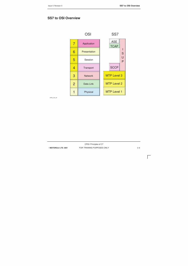
8/4/2019 C7 Principles
http://slidepdf.com/reader/full/c7-principles 95/298
Issue 5 Revision 0 SS7 to OSI Overview
EMOTOROLA LTD. 2001
CP03: Principles of C7
FOR TRAINING PURPOSES ONLY 3–9
SS7 to OSI Overview
CP03_Ch3_04
MTP Level 1
MTP Level 2
MTP Level 3
SCCP
I
S
U
P
TCAP
ASE
MTP Level 1
MTP Level 2
MTP Level 3
SCCP
I
S
U
P
TCAP
ASE
OSI SS7
Data Link
Network
Transport
Session
Presentation
Application
Physical
7
6
5
4
3
2
1
Data Link
Network
Transport
Session
Presentation
Application
Physical
7
6
5
4
3
2
1

8/4/2019 C7 Principles
http://slidepdf.com/reader/full/c7-principles 96/298
Issue 5 Revision 0MTP Layer 1
EMOTOROLA LTD. 2001
CP03: Principles of C7
FOR TRAINING PURPOSES ONLY3–10
MTP Layer 1
The MTP Layer 1 is the physical level and it is virtually the same as the OSI model.Layer 1 defines the physical, electrical and functional characteristics of a signalling datalink and the means to access it. The Layer 1 element provides a bearer for a signalling
link.
In a digital environment, 64 kbit/s digital paths will normally be used for the signallingdata link. The signalling data link may be accessed via a switching function, providing apotential for automatic reconfiguration of signalling links.
S Provides the physical connection between two nodes.
S The protocol should be able to use any type of physical interface.

8/4/2019 C7 Principles
http://slidepdf.com/reader/full/c7-principles 97/298
Issue 5 Revision 0 MTP Layer 1
EMOTOROLA LTD. 2001
CP03: Principles of C7
FOR TRAINING PURPOSES ONLY 3–11
MTP layer 1
CP03_Ch3_05
MTP–L1
MAP ASE
TCAP
SCCP
MTP–L3
MTP–L2
MTP–L1
ISDN –UP
Physical Data Link
8/4/2019 C7 Principles
http://slidepdf.com/reader/full/c7-principles 98/298
Issue 5 Revision 0MTP Layer 2
EMOTOROLA LTD. 2001
CP03: Principles of C7
FOR TRAINING PURPOSES ONLY3–12
MTP Layer 2
Level 2 defines the functions and procedures for, and relating to, the transfer of signallingmessages over one individual signalling data link. The layer 2 functions together with alayer 1 signalling data link as a bearer provide a signalling link for reliable transfer of
signalling messages between two points.
A signalling message delivered by the higher levels is transferred over the signalling linkin variable length signal units. For proper operation of the signalling link, the signal unitcomprises transfer control information in addition to the information content of thesignalling message.
The signalling link functions include:
S Delimitation of signal unit by means of flags;
S Flag imitation prevention by bit stuffing;
S Error detection by means of check bits included in each signal unit;
SError correction by retransmission and signal unit sequence control by means ofexplicit sequence numbers in each signal unit and explicit continuousacknowledgements;
S Signalling link failure detection by means of signal unit error rate monitoring andsignalling link recovery by means of special procedures.

8/4/2019 C7 Principles
http://slidepdf.com/reader/full/c7-principles 99/298
Issue 5 Revision 0 MTP Layer 2
EMOTOROLA LTD. 2001
CP03: Principles of C7
FOR TRAINING PURPOSES ONLY 3–13
MTP layer 2
CP03_Ch3_06
SP
SP SP
SP
MTPMTP – – L1L1MTP–L1
MAP ASE
TCAP
SCCP
MTP–L3
MTP–L2
MTP–L1
ISDN–UP
SS7LINKSP
SP SP
SP
MTPMTP – – L1L1MTP–L1
MAP ASE
TCAP
SCCP
MTP–L3
MTP–L2
MTP–L1
ISDN–UP
SS7LINK

8/4/2019 C7 Principles
http://slidepdf.com/reader/full/c7-principles 100/298

8/4/2019 C7 Principles
http://slidepdf.com/reader/full/c7-principles 101/298
Issue 5 Revision 0 MTP Layer 2 Functionality
EMOTOROLA LTD. 2001
CP03: Principles of C7
FOR TRAINING PURPOSES ONLY 3–15
MTP Layer 2 Functionality
CP03_Ch3_07
Level 1
Level 3
TransmissionBufferTransmissionBuffer
ChecksumgenerationChecksumgenerationChecksumgeneration
Message LengthCheck
Message LengthCheck
RetransmissionBufferRetransmissionBuffer
ReceiveBufferReceiveBuffer
Sequence NumberCheck
Sequence NumberCheck
ChecksumDecodingChecksumDecoding
Bit destuffing
Flag detection
Bit destuffing
Flag detection
Bit stuffing
Flag generation
Bit stuffing
Flag generation
Level 2
IncomingMSUs
IncomingMSUs outgoingMSUs
outgoing MSUs
Supervision(LSSU)
Sequence numbergeneration
Supervision(LSSU)
Supervision(LSSU)
Sequence numbergeneration
Sequence numbergeneration
DelimitationDelimitation
Error detectionError detection
Error correctionError correction

8/4/2019 C7 Principles
http://slidepdf.com/reader/full/c7-principles 102/298
Issue 5 Revision 0MTP Layer 3
EMOTOROLA LTD. 2001
CP03: Principles of C7
FOR TRAINING PURPOSES ONLY3–16
MTP Layer 3
Layer 3 in principle defines those transport functions and procedures that are commonto, and independent of, the operation of individual signalling links.
These functions fall into two major categories:
1. Signalling message handling functions – These are functions that, at the actualtransfer of a message, direct the message to the proper signalling link or UserPart.
2. Signalling network management functions – These are functions that, on the basisof predetermined data and information about the status of the signalling network,control the current message routing and configuration of signalling networkfacilities. In the event of changes in the status, they also control reconfigurationsand other actions to preserve or restore the normal message transfer capability.
The different Layer 3 functions interact with each other and with the functions of otherlevels by means of indications and controls as well as the testing and maintenanceactions may include exchange of signalling messages with corresponding functionslocated at other signalling points. Although not User Parts, these parts of layer 3 can beseen as serving as “User Parts of the Message Transfer Part”. As a convention in thesespecifications, for each description, general references to User Parts as sources or sinksof a signalling message, implicitly include these parts of Layer 3 – unless the opposite isevident from the context or explicitly stated.

8/4/2019 C7 Principles
http://slidepdf.com/reader/full/c7-principles 103/298
Issue 5 Revision 0 MTP Layer 3
EMOTOROLA LTD. 2001
CP03: Principles of C7
FOR TRAINING PURPOSES ONLY 3–17
MTP Layer 3
CP03_Ch3_08
SCP
SSP SSP
STP
STP STP
STP
SCP
MTP–L1
MAP ASE
TCAP
SCCP
MTP–L3
MTP–L2
MTP–L1
ISDN–UP
NETWORKNETWORK
SCP
SCP
SSP SSP
STP
STP STP
STP
SCP
SCP
MTP–L1
MAP ASE
TCAP
SCCP
MTP–L3
MTP–L2
MTP–L1
ISDN–UP
NETWORKNETWORK
8/4/2019 C7 Principles
http://slidepdf.com/reader/full/c7-principles 104/298
Issue 5 Revision 0MTP Layer 3 Functionality
EMOTOROLA LTD. 2001
CP03: Principles of C7
FOR TRAINING PURPOSES ONLY3–18
MTP Layer 3 Functionality
The Layer 3 function is signalling network, and can be divided into two basic categories,Traffic Handling and Signalling Network Management.
Traffic Handling
Traffic Handling has the purpose of ensuring that signalling messages from a User Partat a Signalling Point are delivered to the same user part at the destination indicated bythe sending User Part. The signalling message handling functions are divided into thethree areas detailed below.
Message Discrimination
This determines whether or not the received message is destined to the point itself
Message DistributionThis is used to deliver the received messages to the appropriate user part
Message Routing
This is used at each signalling point to determine the outgoing signalling link on which amessage is forwarded to the destination point.
SignallingNetworkManagement
The Signalling Network Management function is to provide reconfiguration of thesignalling network in the case of failures. The signalling network functions are divided intofour main areas:
Network flow control
The purpose of network flow control is to limit signalling traffic at source, this is done tocontrol congestion of a destination
Network control
This contains the rules and procedures for routing the traffic in both normal and abnormal
states. This provides all the necessary information to traffic handling to perform therouting.
Signalling link Management
This is used to restore failed links, activates idle links and to deactivate aligned signallinglinks, the function monitors and controls signalling resources.
Policing
This is a method by which operators are able to restrict the use of their signalling networkby external operators; this can be implemented in STPs and at the MTP level.

8/4/2019 C7 Principles
http://slidepdf.com/reader/full/c7-principles 105/298
Issue 5 Revision 0 MTP Layer 3 Functionality
EMOTOROLA LTD. 2001
CP03: Principles of C7
FOR TRAINING PURPOSES ONLY 3–19
MTP layer 3 Functionality
CP03_Ch3_09
Traffic Handling
MessageDistribution
MessageDiscrimination
MessageRouting
Traffic Handling
MessageDistributionMessageDistribution
MessageDiscriminationMessageDiscrimination
MessageRoutingMessageRouting
Signalling network management
Networkcontrol
Policing
Network flowcontrol
Signalling resource
management
Signalling network management
NetworkcontrolNetworkcontrol
PolicingPolicing
Network flowcontrolNetwork flowcontrol
Signalling resource
management
Signalling resource
management
IncomingMessage
OutgoingMessage
To UserPart
From UserPart
MTP Layer 2

8/4/2019 C7 Principles
http://slidepdf.com/reader/full/c7-principles 106/298
Issue 5 Revision 0MTP Functionality
EMOTOROLA LTD. 2001
CP03: Principles of C7
FOR TRAINING PURPOSES ONLY3–20
MTP Functionality
Since the Message Transfer Part forms the interface at a node with the rest of thesignalling network, the signalling network will have significant impact on the MTP. TheMTP must however be independent of the signalling network in that it has to be capable
of performing its set functions and attaining its objectives, no matter what networkstructure or status prevails.
The MTP has therefore to contain the necessary functions to ensure any impact that thenetwork has does not impair MTP performance. The components that must beconsidered by the MTP are:
– Signalling points (including signalling transfer points);
– Signalling relations between two signalling points;
– Signalling links;
– Signalling link sets (including link groups);
– Signalling routes; – Signalling route-sets.
The modes applicable to SS No. 7 MTP are:
– Associated mode;
– Quasi–associated mode.
The standard routing label is suitable for national applications. The signalling systemincludes the possibility for using different routing labels nationally.
Message routing is the process of selecting the signalling to be used, for each signallingmessage sent. Message routing is destination-code dependent with an additionalload-sharing element allowing different portions of the signalling traffic to a particular
destination to be distributed over two or more signalling links. This traffic distribution maybe limited to different links within a link set, or applied to links in different link sets.
Message distribution is the process, which, upon receipt of a message at its destinationpoint, determines to which User Part or Layer 3 function the message is to be delivered.
Messagediscrimination
Upon receipt of a message at a signalling point, message discrimination determineswhether or not that point is the destination point of that message. This decision is basedon analysis of the destination code in the routing label in the message. If the signalling
point is the destination point, the message is delivered to the message distributionfunction. If it is not the destination point, and the signalling point has the transfercapability, the message is delivered to the routing function for further transfer on asignalling link.
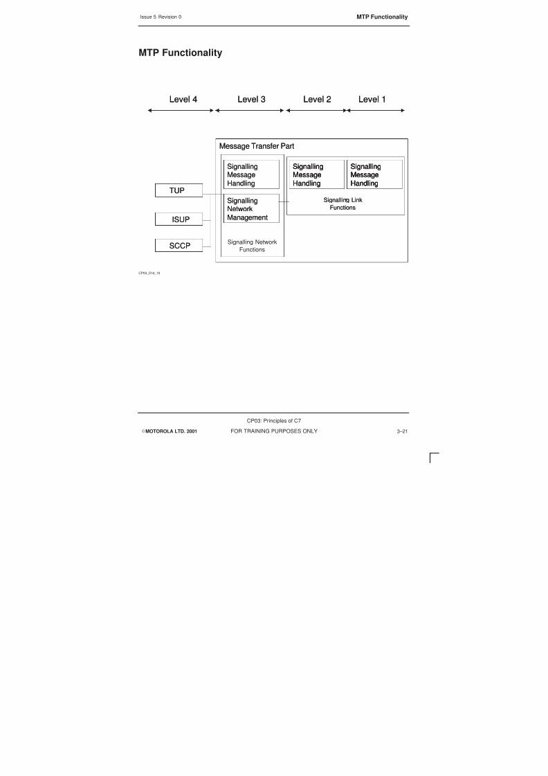
8/4/2019 C7 Principles
http://slidepdf.com/reader/full/c7-principles 107/298
Issue 5 Revision 0 MTP Functionality
EMOTOROLA LTD. 2001
CP03: Principles of C7
FOR TRAINING PURPOSES ONLY 3–21
MTP Functionality
CP03_Ch3_10
Level 1Level 2Level 3Level 4 Level 1Level 2Level 3Level 4
Message Transfer PartMessage Transfer Part
Signalling Network
Functions
SignallingMessage
Handling
SignallingMessage
Handling
SignallingNetwork
Management
SignallingNetwork
Management
SignallingMessage
Handling
SignallingMessage
Handling
SignallingMessage
Handling
SignallingMessage
Handling
SignallingMessage
Handling
SignallingMessage
Handling
Signalling Link
Functions
Signalling Link
Functions
TUP
ISUP
SCCP
TUP
ISUP
SCCP

8/4/2019 C7 Principles
http://slidepdf.com/reader/full/c7-principles 108/298
Issue 5 Revision 0Message Transfer Part
EMOTOROLA LTD. 2001
CP03: Principles of C7
FOR TRAINING PURPOSES ONLY3–22
Message Transfer Part
MTP is responsible for the delivery of messages between switches
The MTP covers the first three levels of the SS7 protocol, the function of MTP is to serve
as a common transport system that provides reliable transmission of signalling messagesbetween communicating users, SS7 network does not equate directly to the OSI model,for the SS7 model to match to the OSI first 3 layers some of the SCCP functionality mustbe included in the MTP, in SS7 the MTP and SCCP is known as the Network ServicePart.
The MTP will ensure that the messages are transferred
S Correctly, all the received messages will be checked before they are accepted
S Without loss or duplication
S In correct sequence
The MTP will also react to system and network features that will affect the reliable
transport of messages and will take the necessary action to ensure a high degree ofreliability.

8/4/2019 C7 Principles
http://slidepdf.com/reader/full/c7-principles 109/298
Issue 5 Revision 0 Message Transfer Part
EMOTOROLA LTD. 2001
CP03: Principles of C7
FOR TRAINING PURPOSES ONLY 3–23
Message transfer Part
CP03_Ch3_11
Data Link
Network
Physical
3
2
1 MTP Level 1
MTP Level 2
MTP Level 3
OSI SS7
Data Link
Network
Physical
3
2
1 MTP Level 1
MTP Level 2
MTP Level 3
OSI SS7

8/4/2019 C7 Principles
http://slidepdf.com/reader/full/c7-principles 110/298
Issue 5 Revision 0SS7 layer 4
EMOTOROLA LTD. 2001
CP03: Principles of C7
FOR TRAINING PURPOSES ONLY3–24
SS7 layer 4
The 4th level in SS7 equate to layers 4–7 in the OSI model, in SS7 the 4th level is knownas the User Parts (UP).
The user parts contain functions connected with the processing of signal information, theUPs generate and analyse signalling messages, they use the MTP as a transportfunction to carry the information to other user parts.
The combination of MTP 1–3 and SCCP is called the Network Services Part.

8/4/2019 C7 Principles
http://slidepdf.com/reader/full/c7-principles 111/298

8/4/2019 C7 Principles
http://slidepdf.com/reader/full/c7-principles 112/298
Issue 5 Revision 0SS7 to OSI layers
EMOTOROLA LTD. 2001
CP03: Principles of C7
FOR TRAINING PURPOSES ONLY3–26
SS7 to OSI layers
SS7 User Parts are
S ISDN User Part (ISUP)
S Telephone User Part (TUP)
S Data User Part (DUP)
S Signalling Connection Control Part (SCCP)
For some applications more complex signalling maybe required, in these casesApplication parts have been defined.
Application parts include
S Mobile Telephony Application Part (MAP)
S Intelligent Network Application Part (INAP)
S
Transaction Capabilities Application Part (TCAP)

8/4/2019 C7 Principles
http://slidepdf.com/reader/full/c7-principles 113/298

8/4/2019 C7 Principles
http://slidepdf.com/reader/full/c7-principles 114/298
Issue 5 Revision 0Signalling Connection Control Part
EMOTOROLA LTD. 2001
CP03: Principles of C7
FOR TRAINING PURPOSES ONLY3–28
Signalling Connection Control Part
SCCP sits at level 4 and is part of the SS7 protocol. It provides the following functions:
S Connectionless and connection oriented network services
S Tracking of application status.
S Transfer of messages between subsystems at the originating and destinationnodes

8/4/2019 C7 Principles
http://slidepdf.com/reader/full/c7-principles 115/298
Issue 5 Revision 0 Signalling Connection Control Part
EMOTOROLA LTD. 2001
CP03: Principles of C7
FOR TRAINING PURPOSES ONLY 3–29
Signalling Connection Control Part
CP03_Ch3_14
Data Link
Network
Transport
Physical
4
3
2
1 MTP Level 1
MTP Level 2
MTP Level 3
SCCP
Data Link
Network
Transport
Physical
4
3
2
1 MTP Level 1
MTP Level 2
MTP Level 3
SCCP
OSI SS7

8/4/2019 C7 Principles
http://slidepdf.com/reader/full/c7-principles 116/298
Issue 5 Revision 0Transaction Capabilities Application Part
EMOTOROLA LTD. 2001
CP03: Principles of C7
FOR TRAINING PURPOSES ONLY3–30
Transaction Capabilities Application Part
TCAP is an SS7 level 4 application and is part of the SS7 Protocol.
TCAP provides a common protocol which allows a large number of applications which
use databases to operate. The protocol is independent of application.
TCAP is responsible for
S Maintaining the connection once it is established.
S Transferring information between nodes to allow applications to operate
S Containing a transaction portion and a component portion.
TCAP provides support for interactive applications in a distributed environment.

8/4/2019 C7 Principles
http://slidepdf.com/reader/full/c7-principles 117/298
Issue 5 Revision 0 Transaction Capabilities Application Part
EMOTOROLA LTD. 2001
CP03: Principles of C7
FOR TRAINING PURPOSES ONLY 3–31
Transaction Capabilities Application Part
CP03_Ch3_15
MTP Level 1
MTP Level 2
MTP Level 3
SCCP
TCAP
MTP Level 1
MTP Level 2
MTP Level 3
SCCP
TCAP
Data Link
Network
Transport
Session
Presentation
Application
Physical
7
6
5
4
3
2
1
Data Link
Network
Transport
Session
Presentation
Application
Physical
7
6
5
4
3
2
1

8/4/2019 C7 Principles
http://slidepdf.com/reader/full/c7-principles 118/298
Issue 5 Revision 0Mobile Application Part (MAP)
EMOTOROLA LTD. 2001
CP03: Principles of C7
FOR TRAINING PURPOSES ONLY3–32
Mobile Application Part (MAP)
For some applications more complex signalling maybe required, in these casesApplication Parts have been defined.
MAP’s functions are to perform signalling within the GSM network, SS7 signalling isrequired between the MSC and all the registers such as HLR, VLR, EIR and AUC.
MAP consists of all signalling messages on the SS7 network that are not call control(ISUP) messages (e.g. statistics, mobility, SMS)
MAP is the interface between TCAP and the application, because the MAP function iscontrol tasks and data exchange between subsystems MAP can be considered anapplication.
As the MAP services are seen as primitives it cannot really be considered to be withinthe OSI reference Model

8/4/2019 C7 Principles
http://slidepdf.com/reader/full/c7-principles 119/298
Issue 5 Revision 0 Mobile Application Part (MAP)
EMOTOROLA LTD. 2001
CP03: Principles of C7
FOR TRAINING PURPOSES ONLY 3–33
Mobile Application Part
CP03_Ch3_16
MTP Level 1
MTP Level 2
MTP Level 3
SCCP
TCAP
MAP
MTP Level 1
MTP Level 2
MTP Level 3
SCCP
TCAP
MAP
Data Link
Network
Transport
Session
Presentation
Application
Physical
7
6
5
4
3
2
1
Data Link
Network
Transport
Session
Presentation
Application
Physical
7
6
5
4
3
2
1

8/4/2019 C7 Principles
http://slidepdf.com/reader/full/c7-principles 120/298
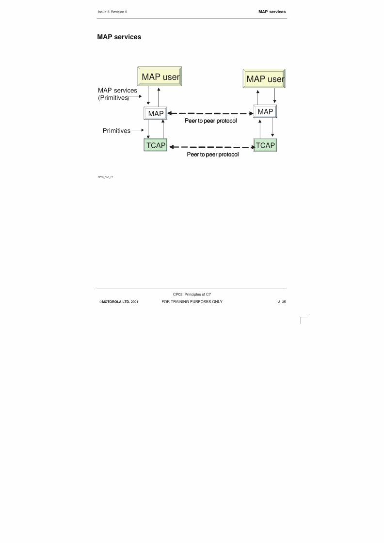
8/4/2019 C7 Principles
http://slidepdf.com/reader/full/c7-principles 121/298
Issue 5 Revision 0 MAP services
EMOTOROLA LTD. 2001
CP03: Principles of C7
FOR TRAINING PURPOSES ONLY 3–35
MAP services
CP03_Ch3_17
MAP
TCAP
MAP
TCAP
MAP user MAP user
Peer to peer protocol
Peer to peer protocol
MAP
TCAP
MAP
TCAP
MAP user MAP user
Peer to peer protocolPeer to peer protocol
Peer to peer protocolPeer to peer protocol
MAP services(Primitives)
Primitives
8/4/2019 C7 Principles
http://slidepdf.com/reader/full/c7-principles 122/298
Issue 5 Revision 0MAP Services and Primitives
EMOTOROLA LTD. 2001
CP03: Principles of C7
FOR TRAINING PURPOSES ONLY3–36
MAP Services and Primitives
The common MAP services can be used to control a communication between MAP andits application. Depending on the task of the service either all, or only some of theprimitives will be used.
The purpose of the special MAP services is to carry the data between MAP and theapplication. It is only a special MAP service that will contain the actual parameters.
Up to four of the primitives could be defined for the special MAP services
Included in the special MAP services are the message types, the local operation code,used to identify the special MAP services within MAP. The primitives used could be“request”, “indication”, “response” and “confirmation”.
It is only the special MAP message that will contain the actual parameter

8/4/2019 C7 Principles
http://slidepdf.com/reader/full/c7-principles 123/298
Issue 5 Revision 0 MAP Services and Primitives
EMOTOROLA LTD. 2001
CP03: Principles of C7
FOR TRAINING PURPOSES ONLY 3–37
Map Services (cont)
CP03_Ch3_18
There are six common MAP services, these are used to control a
communication
Between Map and an application. Depending on the service beingused
either all or only some of the primitives will be used.
Common MAP services
–MAP–DELIMITER
–MAP–OPEN
–MAP–CLOSE
–MAP–U–ABORT (U=user)
–MAP–P–ABORT (P=provider)
–MAP–NOTICE

8/4/2019 C7 Principles
http://slidepdf.com/reader/full/c7-principles 124/298
Issue 5 Revision 0MAP Services and Primitives
EMOTOROLA LTD. 2001
CP03: Principles of C7
FOR TRAINING PURPOSES ONLY3–38

8/4/2019 C7 Principles
http://slidepdf.com/reader/full/c7-principles 125/298
EMOTOROLA LTD. 2001
CP03: Principles of C7
FOR TRAINING PURPOSES ONLY i
Chapter 4
SS7 Network Addressing and
Routing

8/4/2019 C7 Principles
http://slidepdf.com/reader/full/c7-principles 126/298
Issue 5 Revision 0
EMOTOROLA LTD. 2001
CP03: Principles of C7
FOR TRAINING PURPOSES ONLYii

8/4/2019 C7 Principles
http://slidepdf.com/reader/full/c7-principles 127/298
Issue 5 Revision 0
EMOTOROLA LTD. 2001
CP03: Principles of C7
FOR TRAINING PURPOSES ONLY iii
Chapter 4SS7 Network Addressing and Routing i. . . . . . . . . . . . . . . . . . . . . . . . . . . . . . . .
Objectives 4–1. . . . . . . . . . . . . . . . . . . . . . . . . . . . . . . . . . . . . . . . . . . . . . . . . . . . . . . . . . . . . . . . .
Network Addressing 4–2. . . . . . . . . . . . . . . . . . . . . . . . . . . . . . . . . . . . . . . . . . . . . . . . . . . . . . . . .
Point Codes 4–4. . . . . . . . . . . . . . . . . . . . . . . . . . . . . . . . . . . . . . . . . . . . . . . . . . . . . . . . . . . . . . . .
Point Codes 4–6. . . . . . . . . . . . . . . . . . . . . . . . . . . . . . . . . . . . . . . . . . . . . . . . . . . . . . . . . . . . . . . .
Global Title 4–8. . . . . . . . . . . . . . . . . . . . . . . . . . . . . . . . . . . . . . . . . . . . . . . . . . . . . . . . . . . . . . . .
Subsystem Numbering 4–10. . . . . . . . . . . . . . . . . . . . . . . . . . . . . . . . . . . . . . . . . . . . . . . . . . . . . .

8/4/2019 C7 Principles
http://slidepdf.com/reader/full/c7-principles 128/298
Issue 5 Revision 0
EMOTOROLA LTD. 2001
CP03: Principles of C7
FOR TRAINING PURPOSES ONLYiv

8/4/2019 C7 Principles
http://slidepdf.com/reader/full/c7-principles 129/298
Issue 5 Revision 0 Objectives
EMOTOROLA LTD. 2001
CP03: Principles of C7
FOR TRAINING PURPOSES ONLY 4–1
Objectives
At the end of this chapter you will be able to:
S Describe the different types of addressing and routing structures.

8/4/2019 C7 Principles
http://slidepdf.com/reader/full/c7-principles 130/298
Issue 5 Revision 0Network Addressing
EMOTOROLA LTD. 2001
CP03: Principles of C7
FOR TRAINING PURPOSES ONLY4–2
Network Addressing
In an SS7 network the signalling information is not always exchanged between adjacentSPs or STPs
In a GSM system the exchange of information may involve several STPs, as aconsequence the network needs to understand how to each STP is addressed and howcan the system rout the signalling information to the correct point.
The addressing systems work on a national and international basis, with the services ofhigher layers being used for international addressing.

8/4/2019 C7 Principles
http://slidepdf.com/reader/full/c7-principles 131/298
Issue 5 Revision 0 Network Addressing
EMOTOROLA LTD. 2001
CP03: Principles of C7
FOR TRAINING PURPOSES ONLY 4–3
Network Addressing
CP03_Ch4_01
There are three types of network addressing information
these are:
– Point code routing
– Sub system routing
– Global title translation
S
elements

8/4/2019 C7 Principles
http://slidepdf.com/reader/full/c7-principles 132/298
Issue 5 Revision 0Point Codes
EMOTOROLA LTD. 2001
CP03: Principles of C7
FOR TRAINING PURPOSES ONLY4–4
Point Codes
In order to find the destination SP/STP certain signalling messages have routing labels.Contained in the routing label is the Originating Point Code (OPC) (that is the point codeof the sender) and the addressee or Destination Point Code (DPC).
Addressing using signalling point codes will only work on a national basis.

8/4/2019 C7 Principles
http://slidepdf.com/reader/full/c7-principles 133/298
Issue 5 Revision 0 Point Codes
EMOTOROLA LTD. 2001
CP03: Principles of C7
FOR TRAINING PURPOSES ONLY 4–5
Point Codes
CP03_Ch4_02
Point codes are a unique address of a signalling point within
network
Originating point code (OPC)
Destination point code (DPC)
Signalling point code (SPC)
S
S
S
S

8/4/2019 C7 Principles
http://slidepdf.com/reader/full/c7-principles 134/298
Issue 5 Revision 0Point Codes
EMOTOROLA LTD. 2001
CP03: Principles of C7
FOR TRAINING PURPOSES ONLY4–6
Point Codes
If two SPs need to communicate with each other if they are part of the same network, allthat is required is a signalling link between the two SPs.
The key element is the Point Code, this will allow unique addressing of each individualelement within a network.
For example, if the two SPs 1–134 and 1–234, as part of the same networks, areenabled correctly they can communicate without requiring an STP, this would allow fullcommunication between the two points.
If two SPs that are not in the same network, SPs 1–134 and 4–234, which can be eitherdifferent layers or international networks, require to communicate they will require allelements of the signalling networks to be in place. Because the network needs to eithercross network layers or is accessing a different network there is a requirement to gothrough an STP. The STP is the only part of the signalling network that is able to changethe layer on which a network may communicate.

8/4/2019 C7 Principles
http://slidepdf.com/reader/full/c7-principles 135/298
Issue 5 Revision 0 Point Codes
EMOTOROLA LTD. 2001
CP03: Principles of C7
FOR TRAINING PURPOSES ONLY 4–7
Point Code Layers
CP03_Ch4_03
SPSTP
SS7 LINKS
Point Code = 1–334
SS7 LINKS
STP
SS7 LINKS
Point Code = 1–334
SS7 LINKS
SP SPVOICE CIRCUITS
Point Code = 1–134 Point Code = 1–234
SS7 LINKS
SP SPVOICE CIRCUITS
Point Code = 1–134 Point Code = 1–234
SS7 LINKSPoint Code = 4–234Point Code = 4–234
8/4/2019 C7 Principles
http://slidepdf.com/reader/full/c7-principles 136/298
Issue 5 Revision 0Global Title
EMOTOROLA LTD. 2001
CP03: Principles of C7
FOR TRAINING PURPOSES ONLY4–8
Global Title
A Global Title (GT) is not an element within a signalling network that on its own is able toprovide routing within the network, a translation function is required to define the DPC.
A Global Title is an address such as a dialled digit.
The Global Title consists of a directory number and information on how to read thenumber in order to achieve a routing solution.
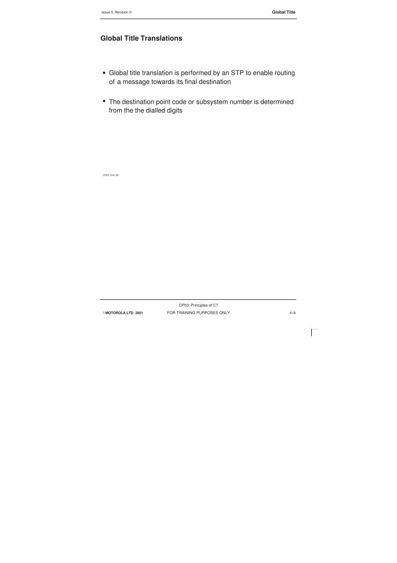
8/4/2019 C7 Principles
http://slidepdf.com/reader/full/c7-principles 137/298
Issue 5 Revision 0 Global Title
EMOTOROLA LTD. 2001
CP03: Principles of C7
FOR TRAINING PURPOSES ONLY 4–9
Global Title Translations
CP03_Ch4_04
Global title translation is performed by an STP to enable routing
a message towards its final destination
The destination point code or subsystem number is determined
from the the dialled digits
S
S
of

8/4/2019 C7 Principles
http://slidepdf.com/reader/full/c7-principles 138/298
Issue 5 Revision 0Subsystem Numbering
EMOTOROLA LTD. 2001
CP03: Principles of C7
FOR TRAINING PURPOSES ONLY4–10
Subsystem Numbering
A Subsystem Number (SSN) is an identification of a specific User Part, each user partwill have its own specific number.
The subsystem is identified either directly as in SCCP or indirectly, using a layer to carrythe signalling MAP.
Subsystem Numbers
SSN (Hex) Subsystem
00 SSN not available
01 SCCP Management
02 Reserved
03 ISUP
04 OMAP
05 MAP
06 HLR
07 VLR
08 MSC
09 EIR
0A AuC
FE NSSAP

8/4/2019 C7 Principles
http://slidepdf.com/reader/full/c7-principles 139/298
Issue 5 Revision 0 Subsystem Numbering
EMOTOROLA LTD. 2001
CP03: Principles of C7
FOR TRAINING PURPOSES ONLY 4–11
Subsystem Numbering
CP03_Ch4_05
The Subsystem Number (SSN) specifies the user that either sent the
SCCP message, or to which subsystem it is addressed.
The SSN is transmitted in the SCCP message and has a hex value
Subsystems might be
SCCP management
ISUP
OMAP
MAP

8/4/2019 C7 Principles
http://slidepdf.com/reader/full/c7-principles 140/298
Issue 5 Revision 0Subsystem Numbering
EMOTOROLA LTD. 2001
CP03: Principles of C7
FOR TRAINING PURPOSES ONLY4–12

8/4/2019 C7 Principles
http://slidepdf.com/reader/full/c7-principles 141/298
EMOTOROLA LTD. 2001
CP03: Principles of C7
FOR TRAINING PURPOSES ONLY i
Chapter 5
SS7 Signalling Units

8/4/2019 C7 Principles
http://slidepdf.com/reader/full/c7-principles 142/298
Issue 5 Revision 0
EMOTOROLA LTD. 2001
CP03: Principles of C7
FOR TRAINING PURPOSES ONLYii

8/4/2019 C7 Principles
http://slidepdf.com/reader/full/c7-principles 143/298
Issue 5 Revision 0
EMOTOROLA LTD. 2001
CP03: Principles of C7
FOR TRAINING PURPOSES ONLY iii
Chapter 5SS7 Signalling Units i. . . . . . . . . . . . . . . . . . . . . . . . . . . . . . . . . . . . . . . . . . . . . . . .
Objectives 5–1. . . . . . . . . . . . . . . . . . . . . . . . . . . . . . . . . . . . . . . . . . . . . . . . . . . . . . . . . . . . . . . . .
Signalling Units Overview 5–2. . . . . . . . . . . . . . . . . . . . . . . . . . . . . . . . . . . . . . . . . . . . . . . . . . . .
Circuit Switch 5–2. . . . . . . . . . . . . . . . . . . . . . . . . . . . . . . . . . . . . . . . . . . . . . . . . . . . . . . . .Message Switch 5–2. . . . . . . . . . . . . . . . . . . . . . . . . . . . . . . . . . . . . . . . . . . . . . . . . . . . . .
Packet Switch 5–2. . . . . . . . . . . . . . . . . . . . . . . . . . . . . . . . . . . . . . . . . . . . . . . . . . . . . . . .
SS7 Packet Switching 5–4. . . . . . . . . . . . . . . . . . . . . . . . . . . . . . . . . . . . . . . . . . . . . . . . . . . . . . .
Signal Unit Packets (Generic) 5–6. . . . . . . . . . . . . . . . . . . . . . . . . . . . . . . . . . . . . . . . . . . . . . . .
Flag 5–8. . . . . . . . . . . . . . . . . . . . . . . . . . . . . . . . . . . . . . . . . . . . . . . . . . . . . . . . . . . . . . . . . . . . . . .
Error Correction and Flow Control 5–10. . . . . . . . . . . . . . . . . . . . . . . . . . . . . . . . . . . . . . . . . . . . .
Error Correction and Flow Control 5–12. . . . . . . . . . . . . . . . . . . . . . . . . . . . . . . . . . . . . . . . . . . . .
FIB p BIB 5–14. . . . . . . . . . . . . . . . . . . . . . . . . . . . . . . . . . . . . . . . . . . . . . . . . . . . . . . . . . . . . . . . . .
Retransmission of Signalling Units 5–16. . . . . . . . . . . . . . . . . . . . . . . . . . . . . . . . . . . . . . . . . . . .
Length Indicator (LI) 5–18. . . . . . . . . . . . . . . . . . . . . . . . . . . . . . . . . . . . . . . . . . . . . . . . . . . . . . . . .
Field Check Sum 5–20. . . . . . . . . . . . . . . . . . . . . . . . . . . . . . . . . . . . . . . . . . . . . . . . . . . . . . . . . . .
Signalling Units Overview 5–22. . . . . . . . . . . . . . . . . . . . . . . . . . . . . . . . . . . . . . . . . . . . . . . . . . . .
Fill in Signal Unit 5–24. . . . . . . . . . . . . . . . . . . . . . . . . . . . . . . . . . . . . . . . . . . . . . . . . . . . . . . . . . . .
Link Status Signal Unit 5–26. . . . . . . . . . . . . . . . . . . . . . . . . . . . . . . . . . . . . . . . . . . . . . . . . . . . . .
LSSU Status Indication 5–28. . . . . . . . . . . . . . . . . . . . . . . . . . . . . . . . . . . . . . . . . . . . . . . . . . . . . .
Link Alignment 5–30. . . . . . . . . . . . . . . . . . . . . . . . . . . . . . . . . . . . . . . . . . . . . . . . . . . . . . . . . . . . .
Link Alignment Test Duration 5–32. . . . . . . . . . . . . . . . . . . . . . . . . . . . . . . . . . . . . . . . . . . . . . . . .
Message Signal Unit 5–34. . . . . . . . . . . . . . . . . . . . . . . . . . . . . . . . . . . . . . . . . . . . . . . . . . . . . . . .Service Information Octet 5–36. . . . . . . . . . . . . . . . . . . . . . . . . . . . . . . . . . . . . . . . . . . . . . . . . . . .
Service Indicator (SI) 5–38. . . . . . . . . . . . . . . . . . . . . . . . . . . . . . . . . . . . . . . . . . . . . . . . . . . . . . . .
Sub-Service Field 5–40. . . . . . . . . . . . . . . . . . . . . . . . . . . . . . . . . . . . . . . . . . . . . . . . . . . . . . . . . . .
Signalling Information Field 5–42. . . . . . . . . . . . . . . . . . . . . . . . . . . . . . . . . . . . . . . . . . . . . . . . . .
Routing Label 5–44. . . . . . . . . . . . . . . . . . . . . . . . . . . . . . . . . . . . . . . . . . . . . . . . . . . . . . . . . . . . . .
SS7 Management and Test Messages 5–46. . . . . . . . . . . . . . . . . . . . . . . . . . . . . . . . . . . . . . . . .
Header Fields 5–48. . . . . . . . . . . . . . . . . . . . . . . . . . . . . . . . . . . . . . . . . . . . . . . . . . . . . . . . . . . . . .
SS7 Network Management and Network Test Messages 5–50. . . . . . . . . . . . . . . . . . . . . . . . .
SS7 Network Management and Network Test Messages 5–52. . . . . . . . . . . . . . . . . . . . . . . . .

8/4/2019 C7 Principles
http://slidepdf.com/reader/full/c7-principles 144/298
Issue 5 Revision 0
EMOTOROLA LTD. 2001
CP03: Principles of C7
FOR TRAINING PURPOSES ONLYiv

8/4/2019 C7 Principles
http://slidepdf.com/reader/full/c7-principles 145/298
Issue 5 Revision 0 Objectives
EMOTOROLA LTD. 2001
CP03: Principles of C7
FOR TRAINING PURPOSES ONLY 5–1
Objectives
At the end of this chapter you will be able to:
S Understand the different types of switching.
S Identify the SS7 signalling units and describe their function and composition.

8/4/2019 C7 Principles
http://slidepdf.com/reader/full/c7-principles 146/298
Issue 5 Revision 0Signalling Units Overview
EMOTOROLA LTD. 2001
CP03: Principles of C7
FOR TRAINING PURPOSES ONLY5–2
Signalling Units Overview
In all networks there are three types of switching, they can either be implementedtogether, working with and over each other, or a network could have one method ofswitching.
Circuit Switch
Where an open circuit is required at all times during the call, such as voice, this isexpensive and wasteful of resources. With the relationship to voice this is currently thebest option because open circuit reduces time delay.
Message Switch
With message switching the circuit is open for as long as each message takes to send.This is good for a point-to-point data transmission. The sending switch does not stayactive but once the message has been sent the circuit closes down
Packet Switch
With the packet switch the circuit is made up only to send the packet of data, the packetsare of a set size, this allows packets that are going to multiple points to be sent down thesame links. This allows a high connection rate to one link. A packet switch will switchuser data and control data.

8/4/2019 C7 Principles
http://slidepdf.com/reader/full/c7-principles 147/298
Issue 5 Revision 0 Signalling Units Overview
EMOTOROLA LTD. 2001
CP03: Principles of C7
FOR TRAINING PURPOSES ONLY 5–3
Signalling units overview
S
CP03_Ch5_01
There are three basic methods of switching within a network
– Circuit switching
– Message switching
– Packet switching

8/4/2019 C7 Principles
http://slidepdf.com/reader/full/c7-principles 148/298
Issue 5 Revision 0SS7 Packet Switching
EMOTOROLA LTD. 2001
CP03: Principles of C7
FOR TRAINING PURPOSES ONLY5–4
SS7 Packet Switching
The SS7 network uses a packet switch to send the information around, this allows a lotof information to be sent and also allows for fewer links to control more points.
If switch A has data to send to switch B, using packet data it does not require the circuitA–B to be active all the time. This means it could be used as a signalling link within adifferent route.
Packets can be sent directly or via different signalling routes. The data arrives at itsdestination and can arrive in any order, this is because the destination is able toreassemble the data in the correct order by using the Packet Assembler/Dissembler(PAD).

8/4/2019 C7 Principles
http://slidepdf.com/reader/full/c7-principles 149/298

8/4/2019 C7 Principles
http://slidepdf.com/reader/full/c7-principles 150/298
Issue 5 Revision 0Signal Unit Packets (Generic)
EMOTOROLA LTD. 2001
CP03: Principles of C7
FOR TRAINING PURPOSES ONLY5–6
Signal Unit Packets (Generic)
The definition of SS7 message types is a functionality of MTP 2. In level 2 of SS7 thereare three different message types. Each one has its own role.
All messages follow the same basic format, the frame structure is laid down by ITU-TQ.701.
All signalling messages are an assembly of information that is to be transferred as a datapacket by the MTP, the signalling information can be exchanged between User Parts,Application Parts or Message Transfer Parts.
The frame structure is as follows:
S A flag to indicate the start
S An acknowledgement field which houses sequence numbers
S A length indicator
S An optional information field the length varies with usage
S The field check sum field
S An end flag.
The end flag may also be used as the start flag for the next frame. Two flags should notbe sequenced.

8/4/2019 C7 Principles
http://slidepdf.com/reader/full/c7-principles 151/298
Issue 5 Revision 0 Signal Unit Packets (Generic)
EMOTOROLA LTD. 2001
CP03: Principles of C7
FOR TRAINING PURPOSES ONLY 5–7
Signal Packet Generic
CP03_Ch5_03
Length
(Bits)
FirstTransmission
Direction
Last FirstTransmission
Direction
Last
Flag FlagFCS Information field Length Acknowledgment
Flag FlagFCS Information field Length Acknowledgment

8/4/2019 C7 Principles
http://slidepdf.com/reader/full/c7-principles 152/298
Issue 5 Revision 0Flag
EMOTOROLA LTD. 2001
CP03: Principles of C7
FOR TRAINING PURPOSES ONLY5–8
Flag
Each signalling unit is enclosed between two flags, the opening flag and closing flag. Theclosing flag may also be the opening flag of the next frame. As a consequence two flagsshould not be sequenced.
The flag is made up of 8 bits, this is a unique 8 bits pattern, 01111110 (zero-sixones-zero). As this is a unique pattern to stop it appearing elsewhere in the signal unit,bit stuffing is used. The sender is responsible for the stuffing and the receiver isresponsible for the removal or de-stuffing.

8/4/2019 C7 Principles
http://slidepdf.com/reader/full/c7-principles 153/298
Issue 5 Revision 0 Flag
EMOTOROLA LTD. 2001
CP03: Principles of C7
FOR TRAINING PURPOSES ONLY 5–9
Flag
CP03_Ch5_04
0 1 1 1 1 1 1 0
LI FlagBSNBI
B
FSNFI
B
SpareFCSFlag
0 1 1 1 1 1 1 0
0 1 1 1 1 1 1 0
LI FlagBSNBI
B
FSNFI
B
SpareFCSFlag
FLAG
FirstTransmission DirectionLast FirstTransmission DirectionLast

8/4/2019 C7 Principles
http://slidepdf.com/reader/full/c7-principles 154/298
Issue 5 Revision 0Error Correction and Flow Control
EMOTOROLA LTD. 2001
CP03: Principles of C7
FOR TRAINING PURPOSES ONLY5–10
Error Correction and Flow Control
The error correction field contains 16 bits and consists of the Forward Sequence Number(FSN), the Backward Sequence Number (BSN), the Forward Information Bit (FIB) andthe Backward Information Bit (BIB).
The error correction field ensures the reception of messages in the right order andrequests resending in case of any error.
Backward Sequence Number (BSN),
There are 7 bits reserved for sequence numbers. The BSN are used to acknowledge thecorrect transmission of a signalling unit.
Backward Information Bit (BIB)
The BIB marks the signalling unit as to the state of received signalling units.
Forward Sequence Number (FSN),There are 7 bits reserved for a 128 modulo counter function, it is stepped up whenever asignalling unit is transmitted, FSN is used to recognise signalling units that are out ofsequence.
Forward Information Bit (FIB)
The FIB informs the receiver if the signalling unit is a retransmission or a first timetransmission.

8/4/2019 C7 Principles
http://slidepdf.com/reader/full/c7-principles 155/298
Issue 5 Revision 0 Error Correction and Flow Control
EMOTOROLA LTD. 2001
CP03: Principles of C7
FOR TRAINING PURPOSES ONLY 5–11
Error Correction Field
CP03_Ch5_05
LI FlagBSNBI
BFSN
FI
BSpareFCSFlag
16 Bits
LI FlagBSNBI
BFSN
FI
BSpareFCSFlag
LI FlagBSNBI
BFSN
FI
BSpareFCSFlag
16 Bits
Error Correction FieldError Correction Field
FirstTransmission DirectionLast FirstTransmission DirectionLast
8/4/2019 C7 Principles
http://slidepdf.com/reader/full/c7-principles 156/298
Issue 5 Revision 0Error Correction and Flow Control
EMOTOROLA LTD. 2001
CP03: Principles of C7
FOR TRAINING PURPOSES ONLY5–12
Error Correction and Flow Control
There are two error correction methods, the Basic Error Correction Method (BASIC) andthe Preventive Cyclic Retransmission Error Correction (PCR).
The Basic Error Correction Method (BASIC)
The receiving terminal sends a negative acknowledgement in response to an incorrectlyreceived signal unit, this will initiate a retransmission of the incorrect message signallingunit and all those that follow.
The Preventive Cyclic Retransmission Error Correction (PCR)
In PCR, retransmission of not positively acknowledged message signal units is initiatedwhen there are no new message signal units to send from the transmission buffer. Thisleads on to the sending of FISUs when the transmission buffer is empty and there are nonew message signalling units to send. Also if a timer is used, once the time frame isover, retransmission takes place. During a period when there are no new signal units to
transmit, all units, which have not been positively acknowledged, will be retransmittedcyclically.
Both methods are used in GSM. The PCR is easier to understand, when a timer has rundown or if no positive acknowledgement is received retransmission takes place.
With the BASIC method, the BSN and FSN use modulo 128 counters to indicate themessage signalling units numbers, the FIB and BIB are used to indicate if the messagesignalling units have been received or to indicate a transmission error.
If the link has just been brought into service all of the values for the FSN, BSN, BIB andFIB are 1, the return information will be of the same values if there are no errors or needto retransmit.
Because FIB= BIB this can be thought of as a positive acknowledgement and the
originating signalling point will now remove the message from the buffer.

8/4/2019 C7 Principles
http://slidepdf.com/reader/full/c7-principles 157/298
Issue 5 Revision 0 Error Correction and Flow Control
EMOTOROLA LTD. 2001
CP03: Principles of C7
FOR TRAINING PURPOSES ONLY 5–13
Error Correction and flow control
CP03_Ch5_06
SP SP
SP SP
FIB = 1, FSN = 50, BIB = 1, BSN= 0FIB = 1, FSN = 50, BIB = 1, BSN= 0
BSN = 50, BIB = 1, FSN = 1, FIB = 1BSN = 50, BIB = 1, FSN = 1, FIB = 1

8/4/2019 C7 Principles
http://slidepdf.com/reader/full/c7-principles 158/298
Issue 5 Revision 0FIB p BIB
EMOTOROLA LTD. 2001
CP03: Principles of C7
FOR TRAINING PURPOSES ONLY5–14
FIB ≠ BIB
The value of the FIB and BIB are the keys to error correction. Both the FIB and BIB are 1bit symbols and can either be 1 or 0.
To indicate a transmission error the BIB is inverted either from 1 to 0 or from 0 to 1, it isthe sending of the inverted BIB that indicates an error.
The function of the FIB is to indicate if the message signalling unit is a retransmission.This is shown by the inversion of the FIB.
When the receiving point receives an incorrect message two actions are taken:
The BIB is inverted, and the FSN of the last correct received message will be insertedinto the BSN field, this will indicate an error to the sending point and which messagesignalling unit needs to be retransmitted.
When it is received at the sending point, the FIB will then be compared to the BIB,because FIB ≠ BIB, it means that it is a negative acknowledgement.
When a negative acknowledgement is received the sending of new signalling units isinterrupted, all signals in the buffer, which have not been positively acknowledged, willnow be retransmitted. Any message signalling units in the buffer that have sequencenumbers that are higher than the retransmitted signal unit will also be retransmitted.
If a signalling message has been lost completely, then because the sequencing numbersare not consecutive, the receiving point is able to ask for retransmission.

8/4/2019 C7 Principles
http://slidepdf.com/reader/full/c7-principles 159/298
Issue 5 Revision 0 FIB p BIB
EMOTOROLA LTD. 2001
CP03: Principles of C7
FOR TRAINING PURPOSES ONLY 5–15
FIB ≠ BIB
CP03_Ch5_06
SP SP
SP SP
FIB = 1, FSN = 51, BIB = 1, BSN= 1FIB = 1, FSN = 51, BIB = 1, BSN= 1
BSN = 50, BIB = 0, FSN= 2, FIB = 1,BSN = 50, BIB = 0, FSN= 2, FIB = 1,

8/4/2019 C7 Principles
http://slidepdf.com/reader/full/c7-principles 160/298
Issue 5 Revision 0Retransmission of Signalling Units
EMOTOROLA LTD. 2001
CP03: Principles of C7
FOR TRAINING PURPOSES ONLY5–16
Retransmission of Signalling Units
The sending point on receipt of the indication of a signalling error will retransmit themessage signalling unit. On transmission the FIB will now be inverted to indicate that thisis a retransmission.
The sending point will then send the signalling unit, on receipt of a successfulre-transmission the receiving point will send message signalling units as normal. If theFIB = BIB then the signalling is correct.

8/4/2019 C7 Principles
http://slidepdf.com/reader/full/c7-principles 161/298
Issue 5 Revision 0 Retransmission of Signalling Units
EMOTOROLA LTD. 2001
CP03: Principles of C7
FOR TRAINING PURPOSES ONLY 5–17
Retransmission of Signalling Unit
CP03_Ch5_08
SP SP
SP SP
FIB = 0, FSN = 51, BIB = 0, BSN= 2FIB = 0, FSN = 51, BIB = 0, BSN= 2
BSN = 51, BIB = 0 , FSN= 3, FIB = 0,BSN = 51, BIB = 0 , FSN= 3, FIB = 0,

8/4/2019 C7 Principles
http://slidepdf.com/reader/full/c7-principles 162/298
Issue 5 Revision 0Length Indicator (LI)
EMOTOROLA LTD. 2001
CP03: Principles of C7
FOR TRAINING PURPOSES ONLY5–18
Length Indicator (LI)
The length indicator is used to distinguish between the types of signalling units, MSU,FISU and LSSU. The LI relates to the length of the optional Data Field.
The field consists of two parts, it is an 8 bit field, the first 6 bits are used to indicate avalue of between 0–63.
The final 2 bits are spare and not currently used.
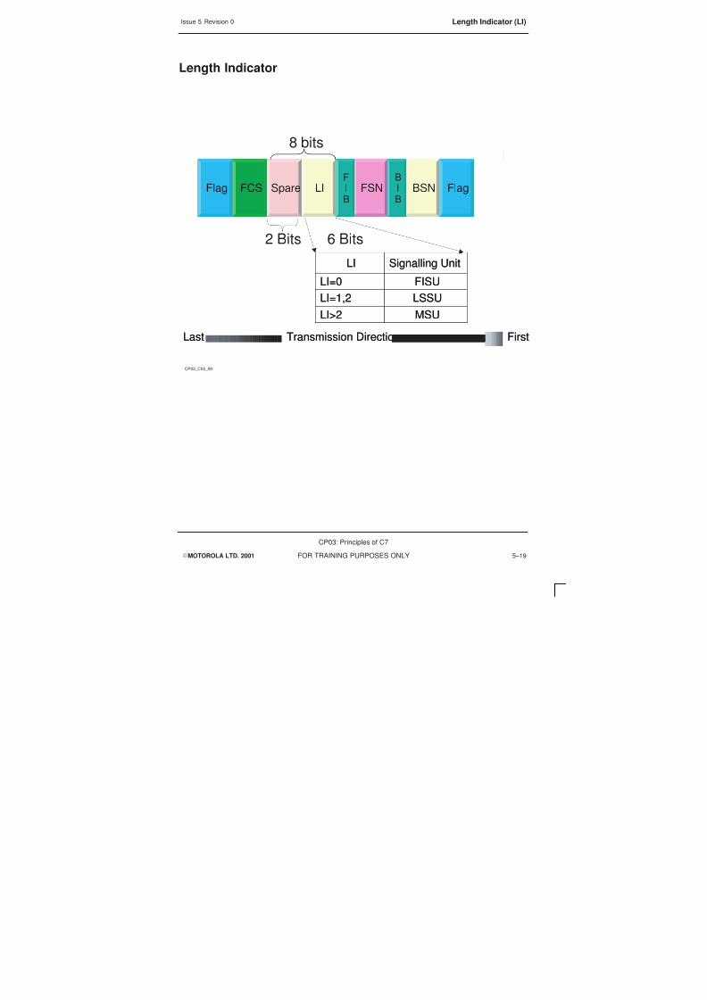
8/4/2019 C7 Principles
http://slidepdf.com/reader/full/c7-principles 163/298
Issue 5 Revision 0 Length Indicator (LI)
EMOTOROLA LTD. 2001
CP03: Principles of C7
FOR TRAINING PURPOSES ONLY 5–19
Length Indicator
CP03_Ch5_09
LI FlagBSNBIB
FSNFIB
SpareFCSFlag
LI FlagBSNBIB
FSNFIB
SpareFCSFlag
8 bits
2 Bits 6 Bits
MSULI>2
LSSULI=1,2
FISULI=0
Signalling UnitLI
MSULI>2
LSSULI=1,2
FISULI=0
Signalling UnitLI
FirstTransmission DirectionLast FirstTransmission Direction
Last
8/4/2019 C7 Principles
http://slidepdf.com/reader/full/c7-principles 164/298
Issue 5 Revision 0Field Check Sum
EMOTOROLA LTD. 2001
CP03: Principles of C7
FOR TRAINING PURPOSES ONLY5–20
Field Check Sum
The error detection function of the message signalling unit is performed by means of the16 bit Field Check Sum (FCS).
The sending terminal generates the check bits, the FCS consists of the preceding bits ofthe signalling unit being applied to a specified algorithm, and the FCS is opened at thereceiving terminal. The same algorithm is applied and the new check sum is compared tothe received. If an error occurs then the error correction operates.

8/4/2019 C7 Principles
http://slidepdf.com/reader/full/c7-principles 165/298
Issue 5 Revision 0 Field Check Sum
EMOTOROLA LTD. 2001
CP03: Principles of C7
FOR TRAINING PURPOSES ONLY 5–21
Field Check Sum
CP03_Ch5_10
LI FlagBSNBIB
FSNFIB
SpareFCSFlag
LI FlagBSNBIB
FSNFIB
SpareFCSFlag
16 Bits
FirstTransmission DirectionLast FirstTransmission Direction
Last
Field used to check the signalling units for errors

8/4/2019 C7 Principles
http://slidepdf.com/reader/full/c7-principles 166/298
Issue 5 Revision 0Signalling Units Overview
EMOTOROLA LTD. 2001
CP03: Principles of C7
FOR TRAINING PURPOSES ONLY5–22
Signalling Units Overview
There are three different formats of messages. The message type is another functionalityof MTP 2, in SS7 level 2 the types of message are defined.
Although no field is available to determine what type the message is, it is possible to doso based on their different lengths, it is the LI that provides the information.

8/4/2019 C7 Principles
http://slidepdf.com/reader/full/c7-principles 167/298
Issue 5 Revision 0 Signalling Units Overview
EMOTOROLA LTD. 2001
CP03: Principles of C7
FOR TRAINING PURPOSES ONLY 5–23
Signalling Units Overview
CP03_Ch5_11
There are three different types of packets in the SS7 network a
these are:
Fill in signal unit (FISU)
Link status signal unit (LSSU)
Message signal unit (MSU)
S
S
S
S

8/4/2019 C7 Principles
http://slidepdf.com/reader/full/c7-principles 168/298
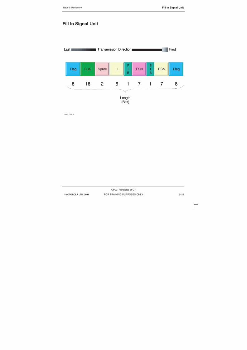
8/4/2019 C7 Principles
http://slidepdf.com/reader/full/c7-principles 169/298
Issue 5 Revision 0 Fill in Signal Unit
EMOTOROLA LTD. 2001
CP03: Principles of C7
FOR TRAINING PURPOSES ONLY 5–25
Fill In Signal Unit
CP03_Ch5_12
Flag BSNBI
B
FSNFI
B
LISpareFCS
Length(Bits)
Flag BSNBI
B
FSNFI
B
LISpareFCS
Length(Bits)
FirstTransmission DirectionLast FirstTransmission DirectionLast
Flag
8 71716216 88 71716216 8

8/4/2019 C7 Principles
http://slidepdf.com/reader/full/c7-principles 170/298
Issue 5 Revision 0Link Status Signal Unit
EMOTOROLA LTD. 2001
CP03: Principles of C7
FOR TRAINING PURPOSES ONLY5–26
Link Status Signal Unit
The Link Status Signal Unit (LSSU) is used to transfer information dealing with thephysical state of the signalling link. The LSSUs are only used to bring a link into service,take a link out of service and during error situations, between two SPs/STPs.
Link Status Signal Units can also be used to align signalling links.
The status field of the LSSU can under ITU-T either be 1 or 2 octets long. This is reallyinconsequential because it is only the first 3 bits that carry actual status information.
The receiver of an LSSU does not confirm its receipt.

8/4/2019 C7 Principles
http://slidepdf.com/reader/full/c7-principles 171/298
Issue 5 Revision 0 Link Status Signal Unit
EMOTOROLA LTD. 2001
CP03: Principles of C7
FOR TRAINING PURPOSES ONLY 5–27
Link Status Signal Unit
CP03_Ch5_13
FirstTransmission DirectionLast FirstTransmission Direction
Last
87171628 or 16
Length(Bits)
168
FCS Status FlagFlag Spare LI
FIB
BIB
FSN BSN
FCS Status FlagFlag Spare LI
FIB
BIB
FSN BSN

8/4/2019 C7 Principles
http://slidepdf.com/reader/full/c7-principles 172/298
Issue 5 Revision 0LSSU Status Indication
EMOTOROLA LTD. 2001
CP03: Principles of C7
FOR TRAINING PURPOSES ONLY5–28
LSSU Status Indication
The term, Status Field, in the LSSU is not normally used and the term Status Informationis used to explain the data that the LSSU carries.
The SF (or status field) according to ITU-T is 1 or 2 octets long, only the first three bits ofthe first octet are used. All other bits are currently spare.
SI is the term STATUS INDICATION
Value Abbreviation Description
0 SIO Start of link alignment
1 SIN A link brought into service with anormal surveillance time of 8.2 secs
2 SIE A link brought into service with anemergency surveillance time of 500
msecs
3 SIOS An error situation or before a link isin service, no MSU’s can be sent or
received
4 SIPO When layer 2 of an SP detects aproblem within layer 3 within it’s ownnode it indicate the problem status to
the peer entity.
5 SIB Signals overload on the originatingside, acknowledgements will not be
sent, link failure usually follows

8/4/2019 C7 Principles
http://slidepdf.com/reader/full/c7-principles 173/298
Issue 5 Revision 0 LSSU Status Indication
EMOTOROLA LTD. 2001
CP03: Principles of C7
FOR TRAINING PURPOSES ONLY 5–29
LSSU Status Indication
CP03_Ch5_14
FirstTransmission DirectionLast FirstTransmission DirectionLast
000 SIO Out of alignment001 SIN Normal Alignment010 SIE Emergency Alignment011 SIOS Out of Service100 SIPO Processor Outage101 SIB Busy
5 or 13 Spare Bits
000 SIO Out of alignment001 SIN Normal Alignment010 SIE Emergency Alignment
011 SIOS Out of Service100 SIPO Processor Outage101 SIB Busy
5 or 13 Spare Bits
Status
8 or 16
Spare LIFCS
Status
8 or 16
Spare LIFCS

8/4/2019 C7 Principles
http://slidepdf.com/reader/full/c7-principles 174/298
Issue 5 Revision 0Link Alignment
EMOTOROLA LTD. 2001
CP03: Principles of C7
FOR TRAINING PURPOSES ONLY5–30
Link Alignment
The operation of a signalling link is a duplex operation – that is the link must be createdin both directions. Both terminals are equal, and as such, both need to establish thecorrect link.
The first stage is the sending of SIOS indicating that the link is in error and out of service(OOS).
The second stage is the sending of the SIO, this is the link out of alignment and the startof alignment.
These steps are returned from the other SP involved in the link, to establish layer 2between the two SPs

8/4/2019 C7 Principles
http://slidepdf.com/reader/full/c7-principles 175/298
Issue 5 Revision 0 Link Alignment
EMOTOROLA LTD. 2001
CP03: Principles of C7
FOR TRAINING PURPOSES ONLY 5–31
Link Alignment
CP03_Ch5_15
LSSU OOS = SIOS
STPSP
STPSP
LSSU OOS = SIOS
LSSU OOS = SIO
LSSU OOS = SIO

8/4/2019 C7 Principles
http://slidepdf.com/reader/full/c7-principles 176/298
Issue 5 Revision 0Link Alignment Test Duration
EMOTOROLA LTD. 2001
CP03: Principles of C7
FOR TRAINING PURPOSES ONLY5–32
Link Alignment Test Duration
The test period is started once the duplex link has been established in layer 2, the LSSUsent depends on the test duration, if the test duration is normal at 8.2 secs, then the SINis sent, the other option, Emergency, the time duration of test is 500 msecs, then the SIE
is sent.
During this time all FISUs that are sent must demonstrate no errors.
The SIE or emergency alignment is only used if no alternative link exists and the linkneeds to be in service.
When the test time is over and layer 2 is in service layer 3 will then initiate further tests,an Signalling Link Test Message (SLTM)is sent for this purpose and it transmits a numberof test octets to layer 3 of the receiving end, if the test is correctly completed by thesending of a Signalling Link Test Acknowledgement (SLTA) message, layer 3 is alsoconsidered to be in traffic.

8/4/2019 C7 Principles
http://slidepdf.com/reader/full/c7-principles 177/298

8/4/2019 C7 Principles
http://slidepdf.com/reader/full/c7-principles 178/298
Issue 5 Revision 0Message Signal Unit
EMOTOROLA LTD. 2001
CP03: Principles of C7
FOR TRAINING PURPOSES ONLY5–34
Message Signal Unit
Message Signalling Units (MSU) are the third type of signalling unit and they are themost diverse. The message signalling units are used for transmission of layer 3information or layer 4 signalling. Whenever an MSU is received it must be acknowledged
to the peer entity.
Layer 3 information includes Signalling Network Management messages (SNM) andSignalling Network Testing and Maintenance messages (SNT).
Layer 4 information is mainly User Parts or Application Parts signalling information.
In the Message Signal Unit the status field is divided into two parts – the ServiceInformation Octet (SIO) and the Signal Information Field (SIF). The Signal InformationOctet is used to associate signalling information with a User Part, while the SignalInformation Field contains the actual user data.

8/4/2019 C7 Principles
http://slidepdf.com/reader/full/c7-principles 179/298
Issue 5 Revision 0 Message Signal Unit
EMOTOROLA LTD. 2001
CP03: Principles of C7
FOR TRAINING PURPOSES ONLY 5–35
Message Signal Unit
CP03_Ch5_17
B
IB
B
IB
FirstTransmission DirectionLast FirstTransmission Direction
Last
87171628n
N< 272
Length(Bits)
168 8
FCS SIF FlagFlag Spare LI
F
IB
FSN BSNSIOFCS SIF FlagFlag Spare LI
F
IB
FSN BSNSIO

8/4/2019 C7 Principles
http://slidepdf.com/reader/full/c7-principles 180/298
Issue 5 Revision 0Service Information Octet
EMOTOROLA LTD. 2001
CP03: Principles of C7
FOR TRAINING PURPOSES ONLY5–36
Service Information Octet
The Service Information Octet (SIO) is 8 bits long and is divided in two parts, the ServiceIndicator (SI) and the Sub-Service Field (SSF). Both of these two sub fields are 4 bits inlength.
The Service Indicator is used to associate signalling information with a User Part and isonly used with MSU messages.
The Sub-Service Field allows for a distinction to be made between national andinternational signalling messages.
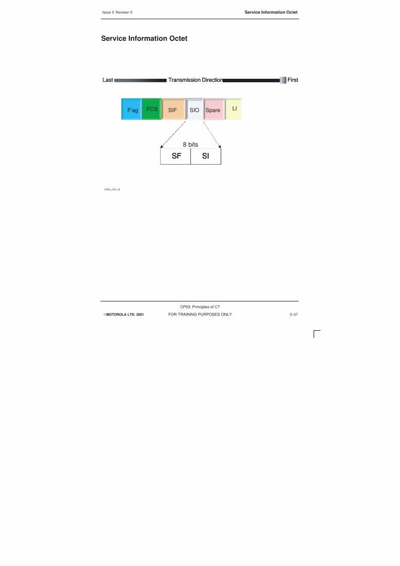
8/4/2019 C7 Principles
http://slidepdf.com/reader/full/c7-principles 181/298
Issue 5 Revision 0 Service Information Octet
EMOTOROLA LTD. 2001
CP03: Principles of C7
FOR TRAINING PURPOSES ONLY 5–37
Service Information Octet
CP03_Ch5_18
FirstTransmission DirectionLast FirstTransmission DirectionLast
8 bits
FCS SIFFlag Spare LISIO
FCS SIFFlag Spare LISIO
SF SISF SISF SI

8/4/2019 C7 Principles
http://slidepdf.com/reader/full/c7-principles 182/298

8/4/2019 C7 Principles
http://slidepdf.com/reader/full/c7-principles 183/298
Issue 5 Revision 0 Service Indicator (SI)
EMOTOROLA LTD. 2001
CP03: Principles of C7
FOR TRAINING PURPOSES ONLY 5–39
Service Indicator
CP03_Ch5_19
FirstTransmission DirectionLast FirstTransmission Direction
Last
8 bitsSF SISF SISF SI
Data User Part (DUP) (call admin)0110
Telephone User Part (TUP)0100
ISDN User Part (ISUP)0101
Service IndicatorDCBA
Signalling Network Testing and Maintenance0001
Data User Part (DUP) (Supp Services)0111
Signalling Connection Control Part (SCCP)0011
Operation and Maintenance Application Part (OMAP)0010
Signalling Network Management0000
FCS SIFFlag Spare LISIO
FCS SIFFlag Spare LISIO

8/4/2019 C7 Principles
http://slidepdf.com/reader/full/c7-principles 184/298
Issue 5 Revision 0Sub-Service Field
EMOTOROLA LTD. 2001
CP03: Principles of C7
FOR TRAINING PURPOSES ONLY5–40
Sub-Service Field
The Sub-Service Field indicates the type of signalling network used. Bits C and D areused to specify if the network is international or national. Bits A and B are used in theUSA for priority but are spare under ETSI.

8/4/2019 C7 Principles
http://slidepdf.com/reader/full/c7-principles 185/298
Issue 5 Revision 0 Sub-Service Field
EMOTOROLA LTD. 2001
CP03: Principles of C7
FOR TRAINING PURPOSES ONLY 5–41
Sub-Service Field
CP03_Ch5_20
FirstTransmission DirectionLast FirstTransmission Direction
Last
8 bitsSF SISF SISF SI
International 10100
Network IndicatorDCBA
National 11100
National 01000
International 00000
International 10100
Network IndicatorDCBA
National 11100
National 01000
International 00000
FCS SIFFlag Spare LISIO
FCS SIFFlag Spare LISIO

8/4/2019 C7 Principles
http://slidepdf.com/reader/full/c7-principles 186/298
Issue 5 Revision 0Signalling Information Field
EMOTOROLA LTD. 2001
CP03: Principles of C7
FOR TRAINING PURPOSES ONLY5–42
Signalling Information Field
The Signalling Information Field (SIF) is the only part of the MSU that refers to the UserPart. The SIF consists of two sub fields, the user information with the contained messageelements and the label field.
The user information is all the information carried in the message-signalling unit thatrelates to the User Part of the message.
The label field refers to the transfer of the message through the signalling system.
MSUs do not need to be exchanged only between adjacent SP/STP. In a GSM systemthe information may involve several STPs.
As SS7 uses signalling Point Codes (SPC) each SP/STP has a unique identifier to map itin the GSM system.
MSUs can be exchanged through SP/STPs and as a result need a routing label withinthe signalling unit, because FISUs and LSSUs are only between adjacent SP/STPs theyhave no requirement for routing labels.
Each type of MSU within the SS7 network has its own label type.

8/4/2019 C7 Principles
http://slidepdf.com/reader/full/c7-principles 187/298
Issue 5 Revision 0 Signalling Information Field
EMOTOROLA LTD. 2001
CP03: Principles of C7
FOR TRAINING PURPOSES ONLY 5–43
Signalling Information Field
CP03_Ch5_21
FirstTransmission DirectionLast FirstTransmission Direction
Last
LabelMessage elements
MTP Management
SCCP User Data
ISUP Information Elements
TUP Information Elements
MTP Management
SCCP User Data
ISUP Information Elements
TUP Information Elements
FCS SIFFlag Spare LISIO
FCS SIFFlag Spare LISIO

8/4/2019 C7 Principles
http://slidepdf.com/reader/full/c7-principles 188/298
Issue 5 Revision 0Routing Label
EMOTOROLA LTD. 2001
CP03: Principles of C7
FOR TRAINING PURPOSES ONLY5–44
Routing Label
The Routing Label is separately defined for each of the User Parts and this label is usedby the MTP to route the message to the correct destination. Each User Part within theSS7 system has its own label format.
Destination Point Code (DPC) indicates the Signalling Point Code of the receiver of thesignalling message
Originating Point Code (OPC) indicates the signalling point code of the sender of thesignalling message
Signalling Link Selection (SLS), these 12 bits have various uses depending on the userpart that the signalling message belongs to.
Depending on the user part the SLS may carry the Circuit Identification Code or it may bea separate field. The Signalling Link Selection (SLS), depending again on the user part,might have its own field or might be imposed in the CIC fields, as in TUP. The length ofthe SLS field allows for the definition of a maximum of 16 signalling links per link set, assuch it is used to determine which Signalling Link within a link set will be used to transferthe message.
If the user part is Signalling Network Management messages (SNM) or SignallingNetwork Testing and Maintenance messages (SNT), then the SLS is replaced bySignalling Link Code (SLC) again 12 bits long but only 4 are used, this indicates theSignalling Link Number.

8/4/2019 C7 Principles
http://slidepdf.com/reader/full/c7-principles 189/298
Issue 5 Revision 0 Routing Label
EMOTOROLA LTD. 2001
CP03: Principles of C7
FOR TRAINING PURPOSES ONLY 5–45
Routing Label
CP03_Ch5_21
FirstTransmission DirectionLast FirstTransmission Direction
Last
Routing LabelRouting Label
Signalling Link Selection (SLS) OPC DPCSignalling Link Selection (SLS) OPC DPC
12/4 bit 14 bit 14 bit
FCS SIFFlag Spare LISIO
FCS SIFFlag Spare LISIO

8/4/2019 C7 Principles
http://slidepdf.com/reader/full/c7-principles 190/298
Issue 5 Revision 0SS7 Management and Test Messages
EMOTOROLA LTD. 2001
CP03: Principles of C7
FOR TRAINING PURPOSES ONLY5–46
SS7 Management and Test Messages
The core of a Message Signalling Unit (MSU) is generated on level 3 or 4. At level 3there are two kinds of MSU that are generated:
S Signalling Network Management messages (SNM-MSU) or
S Signalling Network Testing and Maintenance messages (SNT-MSU).
In the Service Information Octet (SIO) the Service Indicator (SI) identifies the MSU,
0000 for SNM-MSUs
0001 for SNT-MSUs
for these messages contained in the Service Information Field (SIF) after the label willbe the header and then the data field which is optional. This applies only to layer 3.

8/4/2019 C7 Principles
http://slidepdf.com/reader/full/c7-principles 191/298
Issue 5 Revision 0 SS7 Management and Test Messages
EMOTOROLA LTD. 2001
CP03: Principles of C7
FOR TRAINING PURPOSES ONLY 5–47
SS7 Management and Test Messages
CP03_Ch5_23
FirstTransmission DirectionLast FirstTransmission Direction
Last
Routing LabelData Field Heading Code
8n (272 >n>3) bits
32 bits8 bitsData opt.
FCS SIFFlag Spare LISIO
FCS SIFFlag Spare LISIO

8/4/2019 C7 Principles
http://slidepdf.com/reader/full/c7-principles 192/298
Issue 5 Revision 0Header Fields
EMOTOROLA LTD. 2001
CP03: Principles of C7
FOR TRAINING PURPOSES ONLY5–48
Header Fields
Because this is a Layer 3 only, all of the signaling messages will relate to the signallingnetwork and not the user part. It is these dedicated user parts in layer 3 thatautomatically detects error situations.
Errors can be separated into one of three groups
S Overload on a single SS7 link
S Outage/bringing into service an SP/STP
S Outage/bringing into service an SS7 link between SPs/STPs
The SI will already define the MSUs and as such the SIF will be of a set nature.
Heading Code 0 (H0) defines a whole message group, whilst Heading Code 1 (H1) isused to define a single message within the group.

8/4/2019 C7 Principles
http://slidepdf.com/reader/full/c7-principles 193/298
Issue 5 Revision 0 Header Fields
EMOTOROLA LTD. 2001
CP03: Principles of C7
FOR TRAINING PURPOSES ONLY 5–49
Header Fields
CP03_Ch5_24
By using the SI field it is possible to differentiate between user parts
within the network, this is only a layer 3 function, it will indicates what is
contained in both the heading codes and how much of the data field will
used.
The SI field and the Heading Code are necessary for message andmessage –group coding.
Heading code 0 (H0) defines the whole message group.
Heading code 1 (H1) identifies a single message in that group.

8/4/2019 C7 Principles
http://slidepdf.com/reader/full/c7-principles 194/298
Issue 5 Revision 0SS7 Network Management and Network Test Messages
EMOTOROLA LTD. 2001
CP03: Principles of C7
FOR TRAINING PURPOSES ONLY5–50
SS7 Network Management and Network Test Messages
Field H0 and H1 work together to give full message. H0 explains what is being appliedand H1 explains each task to achieve H0
The heading code (H0) is the 4-bit field following the label and identifies the messagegroup.
The different heading codes for message groups are allocated as follows:
0000 Spare
0001 Changeover and change back messages
0010 Emergency changeover message
0011 Transfer-controlled and signalling-route-set congestion messages
0100 Transfer-prohibited-allowed-restricted messages
0101 Signalling-route-set-test messages
0110 Management inhibit messages
0111 Traffic restart allowed message
1000 Signalling-data-link-connection messages
1001 Spare
1010 User part flow control messages
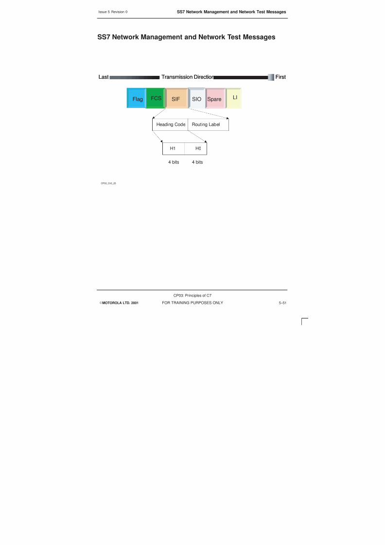
8/4/2019 C7 Principles
http://slidepdf.com/reader/full/c7-principles 195/298
Issue 5 Revision 0 SS7 Network Management and Network Test Messages
EMOTOROLA LTD. 2001
CP03: Principles of C7
FOR TRAINING PURPOSES ONLY 5–51
SS7 Network Management and Network Test Messages
CP03_Ch5_25
FirstTransmission DirectionLast FirstTransmission Direction
Last
Heading Code Routing Label
H1 H0
4 bits 4 bits
FCS SIFFlag Spare LISIO
FCS SIFFlag Spare LISIO

8/4/2019 C7 Principles
http://slidepdf.com/reader/full/c7-principles 196/298

8/4/2019 C7 Principles
http://slidepdf.com/reader/full/c7-principles 197/298

8/4/2019 C7 Principles
http://slidepdf.com/reader/full/c7-principles 198/298
Issue 5 Revision 0SS7 Network Management and Network Test Messages
EMOTOROLA LTD. 2001
CP03: Principles of C7
FOR TRAINING PURPOSES ONLY5–54

8/4/2019 C7 Principles
http://slidepdf.com/reader/full/c7-principles 199/298

8/4/2019 C7 Principles
http://slidepdf.com/reader/full/c7-principles 200/298
Issue 5 Revision 0
EMOTOROLA LTD. 2001
CP03: Principles of C7
FOR TRAINING PURPOSES ONLYii

8/4/2019 C7 Principles
http://slidepdf.com/reader/full/c7-principles 201/298
Issue 5 Revision 0
EMOTOROLA LTD. 2001
CP03: Principles of C7
FOR TRAINING PURPOSES ONLY iii
Chapter 6Signalling Connection Control Part i. . . . . . . . . . . . . . . . . . . . . . . . . . . . . . . . . . .
Objectives 6–1. . . . . . . . . . . . . . . . . . . . . . . . . . . . . . . . . . . . . . . . . . . . . . . . . . . . . . . . . . . . . . . . .
Signalling Connection Control Part 6–2. . . . . . . . . . . . . . . . . . . . . . . . . . . . . . . . . . . . . . . . . . . .
SCCP Signalling Services 6–4. . . . . . . . . . . . . . . . . . . . . . . . . . . . . . . . . . . . . . . . . . . . . . . . . . . .
SCCP Services 6–6. . . . . . . . . . . . . . . . . . . . . . . . . . . . . . . . . . . . . . . . . . . . . . . . . . . . . . . . . . . . .
SCCP Primitives 6–8. . . . . . . . . . . . . . . . . . . . . . . . . . . . . . . . . . . . . . . . . . . . . . . . . . . . . . . . . . . .
SCCP Protocol Classes 6–10. . . . . . . . . . . . . . . . . . . . . . . . . . . . . . . . . . . . . . . . . . . . . . . . . . . . .
SCCP Embedded in MSU 6–12. . . . . . . . . . . . . . . . . . . . . . . . . . . . . . . . . . . . . . . . . . . . . . . . . . . .
SCCP Message 6–14. . . . . . . . . . . . . . . . . . . . . . . . . . . . . . . . . . . . . . . . . . . . . . . . . . . . . . . . . . . .
Routing Label 6–14. . . . . . . . . . . . . . . . . . . . . . . . . . . . . . . . . . . . . . . . . . . . . . . . . . . . . . . . .
Message type code. 6–14. . . . . . . . . . . . . . . . . . . . . . . . . . . . . . . . . . . . . . . . . . . . . . . . . . .
Parameters 6–14. . . . . . . . . . . . . . . . . . . . . . . . . . . . . . . . . . . . . . . . . . . . . . . . . . . . . . . . . .
SCCP Message Structure 6–16. . . . . . . . . . . . . . . . . . . . . . . . . . . . . . . . . . . . . . . . . . . . . . . . . . . .
Message Type Code 6–16. . . . . . . . . . . . . . . . . . . . . . . . . . . . . . . . . . . . . . . . . . . . . . . . . . .
SCCP Routing 6–18. . . . . . . . . . . . . . . . . . . . . . . . . . . . . . . . . . . . . . . . . . . . . . . . . . . . . . . . . . . . .
SCCP Routing Calling Party and Called Party 6–20. . . . . . . . . . . . . . . . . . . . . . . . . . . . . . . . . .
SCCP Addressing for Routing 6–22. . . . . . . . . . . . . . . . . . . . . . . . . . . . . . . . . . . . . . . . . . . . . . . .
SCCP Called Party Address 6–24. . . . . . . . . . . . . . . . . . . . . . . . . . . . . . . . . . . . . . . . . . . . . . . . . .
SCCP Address information 6–26. . . . . . . . . . . . . . . . . . . . . . . . . . . . . . . . . . . . . . . . . . . . . . . . . . .
SCCP Functional Structure 6–28. . . . . . . . . . . . . . . . . . . . . . . . . . . . . . . . . . . . . . . . . . . . . . . . . .

8/4/2019 C7 Principles
http://slidepdf.com/reader/full/c7-principles 202/298
Issue 5 Revision 0
EMOTOROLA LTD. 2001
CP03: Principles of C7
FOR TRAINING PURPOSES ONLYiv

8/4/2019 C7 Principles
http://slidepdf.com/reader/full/c7-principles 203/298
Issue 5 Revision 0 Objectives
EMOTOROLA LTD. 2001
CP03: Principles of C7
FOR TRAINING PURPOSES ONLY 6–1
Objectives
At the end of this chapter you will be able to:
S Identify the SCCP protocol class and describe their functions.
S Explain the connection–oriented and commectionless processes.
S Explain SCCP routing and SCCP management methods.

8/4/2019 C7 Principles
http://slidepdf.com/reader/full/c7-principles 204/298
Issue 5 Revision 0Signalling Connection Control Part
EMOTOROLA LTD. 2001
CP03: Principles of C7
FOR TRAINING PURPOSES ONLY6–2
Signalling Connection Control Part
The Signalling Connection Control Part (SCCP) is a functional entity, which is situatedabove the message transfer part (MTP). In SS7 the SCCP and MTP combine to form theNetwork Service Part (NSP). This then meets the requirements of the network layer –
Layer 3 of the OSI model. SCCP is defined in ITU-T recommendation Q.711– Q.716.
SCCP was designed to communicate with databases without any speech connections. InGSM new protocols have been developed to handle the signalling between the MSC/VLRand BSC the protocol Base Station System Application Part (BSSAP), and for theMSC/VLR and HLR the protocol is Mobile Application Part (MAP). SCCP will work withboth the Transaction Capabilities Application Part (TCAP) and MAP on the interfaces thatare within the Network Switching Subsystem (NSS).
The SCCP maintains both Connection Orientated (CO) and Connection-less (CL)network services. CO services allow the transfer of signals via an established path. COservices are used normally when there are many messages to transfer or if the signallingmessages are so large they need to be segmented. In CL the address required to routethe information to its destination is included in each data packet, no logical connection
between the nodes is established in CL service.
SCCP has addressing capabilities that allow for end-to-end routing. This is possible asthe SCCP supplements the addressing found in MTP which is only possible to deliver amessage to a node by the use of a four bit code. In SCCP the addressing is enhanced bythe use of Destination Point Codes (DPC) and Subsystem Numbers (SSN). A secondfeature in SCCP addressing is the ability to translate Global Titles into DPC and SSN.
Although SCCP is considered a Layer 3 functionality it is able to provide features that areLayer 4, such as error detection and segmentation of data. SCCP also provides its ownmanagement for administrative tasks. These are independent from the SS7 signallingNetwork Management.

8/4/2019 C7 Principles
http://slidepdf.com/reader/full/c7-principles 205/298
Issue 5 Revision 0 Signalling Connection Control Part
EMOTOROLA LTD. 2001
CP03: Principles of C7
FOR TRAINING PURPOSES ONLY 6–3
Signalling Connection Control Part
S
CP03_Ch6_01
SCCP is used by the Base Station Subsystem Application Part
(BSSAP) on the A–interface and by the TCAP and MAP on various
interfaces within the Network Subsystem (NSS)
The SCCP can operate in either the connectionless or connection– orientated service. It also maintains circuit and non–circuit signalling
The SCCP offers end to end addressing even across networks,
national or international.
SCCP also has it’s own management and administrative functions.
S
S
S
either

8/4/2019 C7 Principles
http://slidepdf.com/reader/full/c7-principles 206/298
Issue 5 Revision 0SCCP Signalling Services
EMOTOROLA LTD. 2001
CP03: Principles of C7
FOR TRAINING PURPOSES ONLY6–4
SCCP Signalling Services
The SCCP protocol is able to provide two types of signalling service – Connection-orientated (CO) service and connection-less (CL). Distinguishing betweenconnection-oriented and connection-less service within the SCCP is done using a
parameter called the protocol class.
Connection-orientated (CO) service is when a virtual connection is established betweennodes and identification of the connection is via reference numbers, these being theSource Local Reference (SLR) and the Destination Local Reference (DLR), when theconnection is active data can be exchanged not only between the nodes but also toaddress individual transactions, such as a location update in GSM or a mobile originatingcall.
Connection-less (CL) service is different, there is no referencing, and as a result thereceiver of the message must assign it to an active process, such as paging in theBSSAP.
The SCCP user is the functionality that determines if the connection for SCCP is CO or
CL.

8/4/2019 C7 Principles
http://slidepdf.com/reader/full/c7-principles 207/298
Issue 5 Revision 0 SCCP Signalling Services
EMOTOROLA LTD. 2001
CP03: Principles of C7
FOR TRAINING PURPOSES ONLY 6–5
SCCP Signalling Services
CP03_Ch6_02
Connection–orientated services allow transfer of messages via an
established path, this is used either for multiple messages or when thesignalling message needs to be segmented. BSSAP
Connection–less service is when no logical path is established and theSCCP message will contain the destination. MAP or BSSAP
MTP Level 3
SCCP
MAP
TCAP
BSSAP
CL CO
DTAPBSSMAP
MTP Level 3
SCCP
MAP
TCAP
BSSAP
CL CO
DTAPBSSMAP
S
S

8/4/2019 C7 Principles
http://slidepdf.com/reader/full/c7-principles 208/298
Issue 5 Revision 0SCCP Services
EMOTOROLA LTD. 2001
CP03: Principles of C7
FOR TRAINING PURPOSES ONLY6–6
SCCP Services
The connection-oriented services enable the transfer of signalling over establishedsignalling connections. These connections are either temporary or permanent. If theconnection is a temporary connection the control of signalling can be divided into three
phases.
1. Connection Establishment – this provides the method to establish the signallingconnection. At this stage both the reference numbers are assigned to the link andeach node.
2. Data transfer – this provides the transfer of data in Network Service Data Units(NSDU). The transfer can be in simultaneous directions or in answer responsemethod. The data transfer service is compiled of SCCP messages. the SCCPmessage contains two elements – Network Protocol Information (NPCI) andNetwork Service Data Unit (NSDU).
S Network Protocol Control Information (NPCI)
The NPCI contains a connection reference number that allocated the
message to a signalling connection.
S Network Service Data Unit (NSDU)
The NSDU contains the user data, if the data is too large for one SCCPmessage to be carried in the SIF of an SS7 message the protocol class willcontrol segmenting and reassembling
3. Connection release – this provides the method to breakdown the connection andrelease of the reference numbers.
The permanent connections have the same phases as temporary connection but mayhave additional safeguarding mechanisms at the end points to ensure re-establishment incase of processor outage.
In connectionless signalling all data for routing is carried in each data packet, so nological path is created in the network, the functions of the connectionless service are,mapping of the network address to signalling relations, sequence services andsegmenting.

8/4/2019 C7 Principles
http://slidepdf.com/reader/full/c7-principles 209/298
Issue 5 Revision 0 SCCP Services
EMOTOROLA LTD. 2001
CP03: Principles of C7
FOR TRAINING PURPOSES ONLY 6–7
SCCP services
CP03_Ch6_03
Connection orientated transfer mode can be divided into three phases
Establishing the connection
Data transfer
Release of the connection
Connection less orientated transfer all of the information required to routethe data to its destination is contained in each packet.

8/4/2019 C7 Principles
http://slidepdf.com/reader/full/c7-principles 210/298
Issue 5 Revision 0SCCP Primitives
EMOTOROLA LTD. 2001
CP03: Principles of C7
FOR TRAINING PURPOSES ONLY6–8
SCCP Primitives
SCCP is a layer within the SS7. Because SCCP is not a top layer or a base layer itmeans that it must be able to transfer information and communicate with the layersabove and below it in the protocol stack.
Layers either side of the SCCP are known as the service user and the SCCP is theservice provider, communication is achieved using Service Primitives.
Primitives consist of commands and responses that are associated with the servicesrequested of the layers. Service primitives are data units sent between layers to invoke adifferent procedure.
There is a general syntax applied to all primitives:-
Layer Identifier Generic Name Specific Name Parameter
The Layer Identifier specifies which layer is providing the service e.g. N=SCCP,MTP=MTP, TR=transaction sub layer TCAP, TC=service provider in TCAP
The Generic Name defines the action to be performed
The Specific Name indicates the purpose of the primitive, it also indicates the direction ofprimitive flow.
The parameter contains elements of information that will be transferred between layers.

8/4/2019 C7 Principles
http://slidepdf.com/reader/full/c7-principles 211/298
Issue 5 Revision 0 SCCP Primitives
EMOTOROLA LTD. 2001
CP03: Principles of C7
FOR TRAINING PURPOSES ONLY 6–9
Primitive Structure
CP03_Ch6_04
MTP Level 3
SCCP
ISUP
TCAP
ServicePrimitives
ServicePrimitives
ServicePrimitives
Network Service Part
Service Access Point
8/4/2019 C7 Principles
http://slidepdf.com/reader/full/c7-principles 212/298
Issue 5 Revision 0SCCP Protocol Classes
EMOTOROLA LTD. 2001
CP03: Principles of C7
FOR TRAINING PURPOSES ONLY6–10
SCCP Protocol Classes
The protocol used by SCCP to provide network services is divided into four classes.
Two classes are defined for each signalling services, 0 and 1 represent the
connection-less service and 2 and 3 represent the connection-orientated services.
Class 0 and 2 form the basic version whilst 1 and 3 allow for additional data security andsegmentation.
In GSM protocol classes 0,1 and 2 are used, class 3 is never used in GSM
Over the A interface protocol classes, 0 and 2 are used.
When using GSM MAP protocol classes, 0 and 2 are used
Protocol class 0 – the NSDUs are transported independently of each other and may bedelivered out of sequence, this protocol class is a pure connection-less network service
Protocol class 1 – all the features of class 0 are included and added to. An additionalsequencing feature is added and the signalling link selection is encoded into the routing
label. This is a connection-less network service.
Protocol class 2 – allows for bi-directional transfer of NSDUs and it ensures sequencingas in protocol class 1. This corresponds to a connection-oriented network service.

8/4/2019 C7 Principles
http://slidepdf.com/reader/full/c7-principles 213/298
Issue 5 Revision 0 SCCP Protocol Classes
EMOTOROLA LTD. 2001
CP03: Principles of C7
FOR TRAINING PURPOSES ONLY 6–11
SCCP Protocol Classes
CP03_Ch6_05
There are four Protocol classes defined within the SCCP protocol
Protocol Classes
Dataform2 packets DT2Flow Control Connection–orientated Class3
Dataform1 packets DT1Basic Connection–orientated Class2
Unit Data (UDT) or UnitData Service (UDTS)
Sequenced Connection–less class1
Unit Data (UDT) or UnitData Service (UDTS)
Basic Connection–less Class0
Dataform2 packets DT2Flow Control Connection–orientated Class3
Dataform1 packets DT1Basic Connection–orientated Class2
Unit Data (UDT) or UnitData Service (UDTS)
Sequenced Connection–less class1
Unit Data (UDT) or UnitData Service (UDTS)
Basic Connection–less Class0
8/4/2019 C7 Principles
http://slidepdf.com/reader/full/c7-principles 214/298
Issue 5 Revision 0SCCP Embedded in MSU
EMOTOROLA LTD. 2001
CP03: Principles of C7
FOR TRAINING PURPOSES ONLY6–12
SCCP Embedded in MSU
SCCP messages are carried on signalling links by means of MSUs.
The Service Indicator (SI) in the Service Information Octet (SIO) is coded to 0011 to
indicate that the payload of the Signalling Information Field (SIF) is an SCCP. The maxsize of the SCCP message is 272 octets.
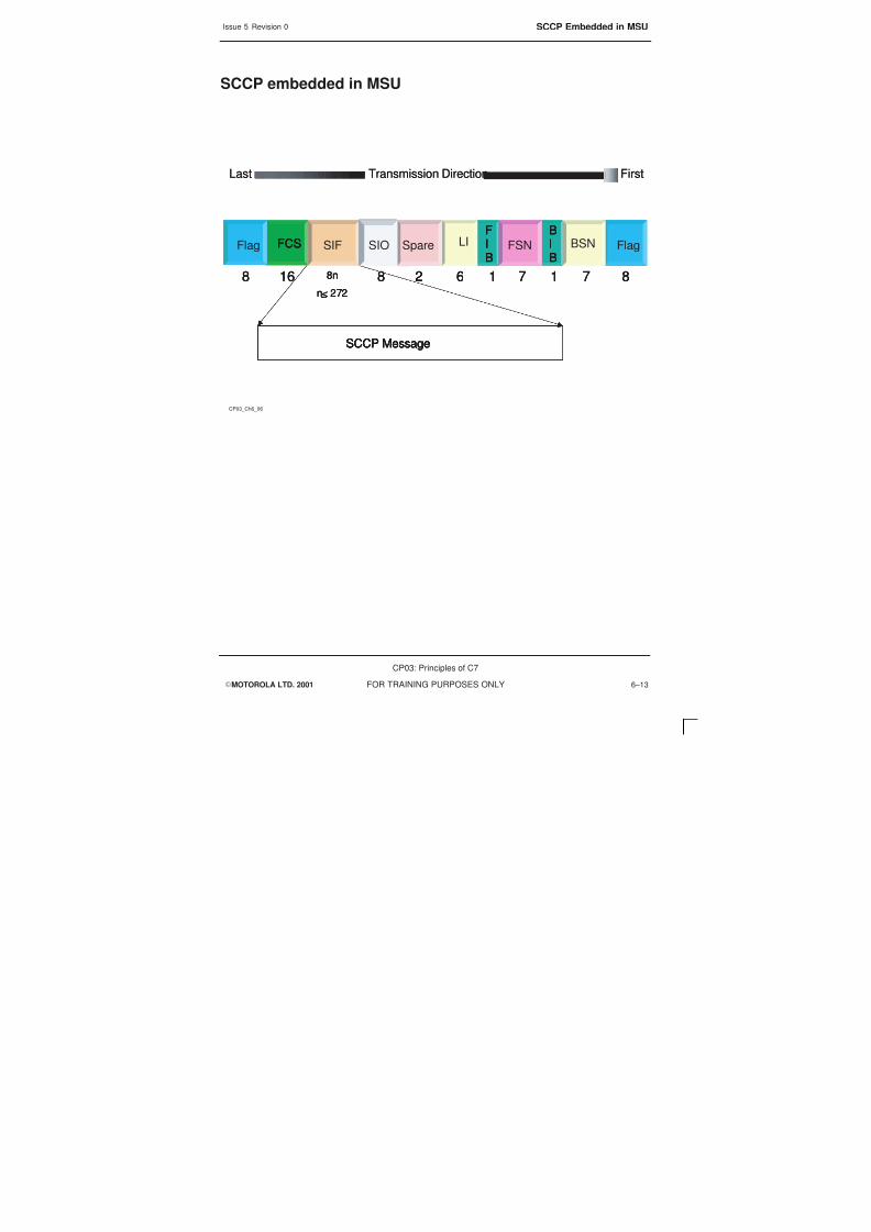
8/4/2019 C7 Principles
http://slidepdf.com/reader/full/c7-principles 215/298

8/4/2019 C7 Principles
http://slidepdf.com/reader/full/c7-principles 216/298

8/4/2019 C7 Principles
http://slidepdf.com/reader/full/c7-principles 217/298
Issue 5 Revision 0 SCCP Message
EMOTOROLA LTD. 2001
CP03: Principles of C7
FOR TRAINING PURPOSES ONLY 6–15
Signalling Connection Control Part Msg
CP03_Ch6_07
FirstTransmission DirectionLast FirstTransmission DirectionLast
Routing LabelMandatory variable Part Message type Code
8n (272 >n>3) bits
Mandatory Fixed Part
Parameters
FCS SIFFlag Spare LISIO
FCS SIFFlag Spare LISIO

8/4/2019 C7 Principles
http://slidepdf.com/reader/full/c7-principles 218/298
Issue 5 Revision 0SCCP Message Structure
EMOTOROLA LTD. 2001
CP03: Principles of C7
FOR TRAINING PURPOSES ONLY6–16
SCCP Message Structure
The complete message is hosted by the MSU. The SCCP breaks down into various partsand the SCCP message that is sent will have three types of fields filled as laid out byITU-T.
Message TypeCode
This is the protocol class, it is using the message type code that the SCCP includes inthe MSU. The message type will also indicate if it is a CO or CL service. For CL themessage is either Unit Data (UDT) or Unit Data Service (UDTS). For CO the messagewill be Data form 1 (DT1).
The parameters are further broken down into two sub fields.
S Mandatory fixed Part
S Mandatory variable Part
The contents of these two sub fields are specific for each SCCP message. This isbecause each SCCP message has its specific number and type of parameters. Thelength of these can be fixed or variable.
The Mandatory Part includes segmentation information, Destination/Source LocationRegister DLR/SLR, or calling party and called party address.

8/4/2019 C7 Principles
http://slidepdf.com/reader/full/c7-principles 219/298
8/4/2019 C7 Principles
http://slidepdf.com/reader/full/c7-principles 220/298

8/4/2019 C7 Principles
http://slidepdf.com/reader/full/c7-principles 221/298
Issue 5 Revision 0 SCCP Routing
EMOTOROLA LTD. 2001
CP03: Principles of C7
FOR TRAINING PURPOSES ONLY 6–19
SCCP routing
CP03_Ch6_09
When SCCP is used to transfer a message, two parameters are used toroute it to the next node
– Called Party Address
– Calling Party Address
Both parts are included in connection–less Unidata and Unidata services.

8/4/2019 C7 Principles
http://slidepdf.com/reader/full/c7-principles 222/298
Issue 5 Revision 0SCCP Routing Calling Party and Called Party
EMOTOROLA LTD. 2001
CP03: Principles of C7
FOR TRAINING PURPOSES ONLY6–20
SCCP Routing Calling Party and Called Party
Within the SCCP message structure there must be parameters that enable non-circuitrelated signalling for point-to-point communication between two users.
These address parameters are Called Party Address (CdPA) and Calling Party Address(CaPA). The format of these two sub fields is the same and they identify the type ofaddress and the address itself.
An address may consist of any combination the following,
S SPC
S SSN
S Global Title
The parameters CaPA and CdPA are necessary for end-to-end addressing of SCCPmessages
MAP uses all possible combinations for addressing, while BSSAP requires only the SPC
and SSN.

8/4/2019 C7 Principles
http://slidepdf.com/reader/full/c7-principles 223/298
Issue 5 Revision 0 SCCP Routing Calling Party and Called Party
EMOTOROLA LTD. 2001
CP03: Principles of C7
FOR TRAINING PURPOSES ONLY 6–21
SCCP Routing Calling Party and Called Party
CP03_Ch6_10
The calling –party address ( CaPA) and the called–party address (CdPA)
have the same format and also identify the type of address beingused.
The address may consist of any combination of the following
– SPC
– SSN
– Global title
S
S

8/4/2019 C7 Principles
http://slidepdf.com/reader/full/c7-principles 224/298

8/4/2019 C7 Principles
http://slidepdf.com/reader/full/c7-principles 225/298
Issue 5 Revision 0 SCCP Addressing for Routing
EMOTOROLA LTD. 2001
CP03: Principles of C7
FOR TRAINING PURPOSES ONLY 6–23
SCCP Addressing for Routing
CP03_Ch6_11
There are two methods of addresses for SCCP routing
– Global title (GT), is a destination address, it is used by different
nodes to solve routing
– DPC and SSN, this allows direct routing, as a result no
translation is required by the SCCP

8/4/2019 C7 Principles
http://slidepdf.com/reader/full/c7-principles 226/298
Issue 5 Revision 0SCCP Called Party Address
EMOTOROLA LTD. 2001
CP03: Principles of C7
FOR TRAINING PURPOSES ONLY6–24
SCCP Called Party Address
The format of the Called Party Address (CdPA) and the Calling Party Address (CaPA)are the same, so by looking at one it is possible to explain both.
The Called Party Address field breaks down into three sub fields:
Address Length. This indicates the amount of information in the SCCP address subfield.
Address Indicator. Because address information handled by the SCCP can appear indifferent variants, it is then practical to have a sub field that defines the structure of theaddress related information.
SCCP address. This is made up from the Sub-System Number (SSN), Signaling PointCode (SPC) and Global Title (GT) (which is defined by lower level parameters).

8/4/2019 C7 Principles
http://slidepdf.com/reader/full/c7-principles 227/298
Issue 5 Revision 0 SCCP Called Party Address
EMOTOROLA LTD. 2001
CP03: Principles of C7
FOR TRAINING PURPOSES ONLY 6–25
SCCP Called Party Addressing
CP03_Ch6_12
Address LengthSSN Address IndicatorSPCGT Address LengthSSN Address IndicatorSPCGT
FirstTransmission DirectionLast
SCCP Address
FirstTransmission Direction
Last FirstTransmission Direction
Last
SCCP Address
Point Code IndicatorGT Indicator SSN IndicatorRouting IndicatorSpare Point Code IndicatorGT Indicator SSN IndicatorRouting IndicatorSpare Point Code IndicatorGT Indicator SSN IndicatorRouting IndicatorSpare
0=SPC not included1=SPC included
0=SPC not included1=SPC included
0=SPC not included1=SPC included
0=SSN not included1=SSN included
0=SSN not included1=SSN included
0=SSN not included1=SSN included
0000=GT not included00010010
=GT included00110100
0000=GT not included00010010
=GT included00110100
0000=GT not included00010010
=GT included00110100
Routing based on0=GT1=DPC+SSN
Routing based on0=GT1=DPC+SSN
Routing based on0=GT1=DPC+SSN

8/4/2019 C7 Principles
http://slidepdf.com/reader/full/c7-principles 228/298

8/4/2019 C7 Principles
http://slidepdf.com/reader/full/c7-principles 229/298
Issue 5 Revision 0 SCCP Address information
EMOTOROLA LTD. 2001
CP03: Principles of C7
FOR TRAINING PURPOSES ONLY 6–27
SCCP Address Information
CP03_Ch6_13
MTP
SCCP
MAP
TCAP
MTP
SCCP
MAP
TCAP
Routing Label
Calling Address
Called Address
Routing LabelRouting Label
Calling AddressCalling Address
Called AddressCalled Address
DPC
OPC
DPC
DPC
OPC
OPC
Translation type
Numbering Plan
Nature of Address
Address Information
Translation type
Translation type
Numbering Plan
Numbering Plan
Nature of Address
Nature of Address
Address Information
Address Information
Global Title
SSN
SPC
Global Title
Global Title
SSN
SSN
SPC
SPC

8/4/2019 C7 Principles
http://slidepdf.com/reader/full/c7-principles 230/298
Issue 5 Revision 0SCCP Functional Structure
EMOTOROLA LTD. 2001
CP03: Principles of C7
FOR TRAINING PURPOSES ONLY6–28
SCCP Functional Structure
The SCCP is able to transfer messages both to higher layers, SCCP Users and aroundthe network using MTP, in order to do so it must have separate functionality within theSCCP to achieve this
The SCCP function consists of the following main sub functions:
SCCP Connection-Oriented Control (SCOC). The function of the SCOC is to control theestablishment and release of signalling connection and to provide for data transfer onsignalling connections.
SCCP Connectionless Control (SSLC). This sub function is responsible for theconnectionless transfer of data units.
SCCP Management (SCM). The purpose of the SCCP Management is to providecapabilities to handle the congestion or failure of the SCCP, the SCCP user or thesignalling route to the SCCP/SCCP user. These are in addition to the MTPs signallingroute management and flow control.
SCCP Routing Control. On receipt of a message from the MTP or any of the above subfunctions, the SCCP Routing Control provides the necessary routing functions to forwardthe message. If the called party is a local user then the message is passed to eitherSCOC, SSLC or SCM. If the called party is not a local user, then it is passed to MTP fortransfer to a distant SCCP user.

8/4/2019 C7 Principles
http://slidepdf.com/reader/full/c7-principles 231/298
Issue 5 Revision 0 SCCP Functional Structure
EMOTOROLA LTD. 2001
CP03: Principles of C7
FOR TRAINING PURPOSES ONLY 6–29
SCCP Functional Structure
CP03_Ch6_14
SCCP MTPSCCP MTP
SCCP
Management
(SCM)
SCCP
Connectionless
Control(SCLC)
SCCPConnection
Oriented
Control(SCOC) SCCPRouting
Control(SCRC)
MTPSCCP
USERS

8/4/2019 C7 Principles
http://slidepdf.com/reader/full/c7-principles 232/298
Issue 5 Revision 0SCCP Functional Structure
EMOTOROLA LTD. 2001
CP03: Principles of C7
FOR TRAINING PURPOSES ONLY6–30

8/4/2019 C7 Principles
http://slidepdf.com/reader/full/c7-principles 233/298
EMOTOROLA LTD. 2001
CP03: Principles of C7
FOR TRAINING PURPOSES ONLY i
Chapter 7
Transaction Capabilities
Application Part and Mobile
Application Part

8/4/2019 C7 Principles
http://slidepdf.com/reader/full/c7-principles 234/298
Issue 5 Revision 0
EMOTOROLA LTD. 2001
CP03: Principles of C7
FOR TRAINING PURPOSES ONLYii

8/4/2019 C7 Principles
http://slidepdf.com/reader/full/c7-principles 235/298
Issue 5 Revision 0
EMOTOROLA LTD. 2001
CP03: Principles of C7
FOR TRAINING PURPOSES ONLY iii
Chapter 7Transaction Capabilities Application Part and Mobile Application Part i. .
Objectives 7–1. . . . . . . . . . . . . . . . . . . . . . . . . . . . . . . . . . . . . . . . . . . . . . . . . . . . . . . . . . . . . . . . .
Transaction Capabilities Application Part (TCAP) 7–2. . . . . . . . . . . . . . . . . . . . . . . . . . . . . . . .
Purpose of TCAP 7–4. . . . . . . . . . . . . . . . . . . . . . . . . . . . . . . . . . . . . . . . . . . . . . . . . . . . . . . . . . .
Mobile Application Part 7–6. . . . . . . . . . . . . . . . . . . . . . . . . . . . . . . . . . . . . . . . . . . . . . . . . . . . . .
MAP Application Entities 7–8. . . . . . . . . . . . . . . . . . . . . . . . . . . . . . . . . . . . . . . . . . . . . . . . . . . . .
TCAP and MAP Interworking 7–10. . . . . . . . . . . . . . . . . . . . . . . . . . . . . . . . . . . . . . . . . . . . . . . . .
TCAP and MAP in the OSI Model 7–12. . . . . . . . . . . . . . . . . . . . . . . . . . . . . . . . . . . . . . . . . . . . .
AE Functionality 7–14. . . . . . . . . . . . . . . . . . . . . . . . . . . . . . . . . . . . . . . . . . . . . . . . . . . . . . . . . . . .
TCAP Structure 7–16. . . . . . . . . . . . . . . . . . . . . . . . . . . . . . . . . . . . . . . . . . . . . . . . . . . . . . . . . . . .
The Component Sub Layer (CSL) 7–16. . . . . . . . . . . . . . . . . . . . . . . . . . . . . . . . . . . . . . .
The Transaction Sub layer (TSL) 7–16. . . . . . . . . . . . . . . . . . . . . . . . . . . . . . . . . . . . . . . .
TCAP Message Interfaces 7–18. . . . . . . . . . . . . . . . . . . . . . . . . . . . . . . . . . . . . . . . . . . . . . . . . . .TCAP Embedded Message Structure 7–20. . . . . . . . . . . . . . . . . . . . . . . . . . . . . . . . . . . . . . . . . .
TCAP Information Elements 7–22. . . . . . . . . . . . . . . . . . . . . . . . . . . . . . . . . . . . . . . . . . . . . . . . . .
Primitives and Constructor IE 7–24. . . . . . . . . . . . . . . . . . . . . . . . . . . . . . . . . . . . . . . . . . . . . . . . .
TCAP Message Structure 7–26. . . . . . . . . . . . . . . . . . . . . . . . . . . . . . . . . . . . . . . . . . . . . . . . . . . .
TCAP Transaction Procedures 7–28. . . . . . . . . . . . . . . . . . . . . . . . . . . . . . . . . . . . . . . . . . . . . . .
MAP user Communication 7–30. . . . . . . . . . . . . . . . . . . . . . . . . . . . . . . . . . . . . . . . . . . . . . . . . . .
TCAP/MAP Transactions 7–32. . . . . . . . . . . . . . . . . . . . . . . . . . . . . . . . . . . . . . . . . . . . . . . . . . . .

8/4/2019 C7 Principles
http://slidepdf.com/reader/full/c7-principles 236/298
Issue 5 Revision 0
EMOTOROLA LTD. 2001
CP03: Principles of C7
FOR TRAINING PURPOSES ONLYiv

8/4/2019 C7 Principles
http://slidepdf.com/reader/full/c7-principles 237/298
Issue 5 Revision 0 Objectives
EMOTOROLA LTD. 2001
CP03: Principles of C7
FOR TRAINING PURPOSES ONLY 7–1
Objectives
At the end of this chapter you will be able to:
S Describe the functionality of TCAP and MAP.
S Identify the portions of the TCAP and MAP environment.
S Identify the TCAP message structure and explain the function of the elements.
S Describe the procedure for a TCP transaction.
8/4/2019 C7 Principles
http://slidepdf.com/reader/full/c7-principles 238/298
Issue 5 Revision 0Transaction Capabilities Application Part (TCAP)
EMOTOROLA LTD. 2001
CP03: Principles of C7
FOR TRAINING PURPOSES ONLY7–2
Transaction Capabilities Application Part (TCAP)
Transaction Capabilities Application Part (TCAP) was introduced above the SCCP andMTP as a reaction for the need to deal with increasing Database-to-Databasecommunication. TCAP uses SCCP to carry the information throughout the signalling
network and it is TCAP that provides the core functionality to support roaming.
TCAP is the serving interface between SCCP and the functionality that sits above TCAPproviding GSM with a lot of dialogues running concurrently with a wide variety ofmessages carrying numerous parameters. These communications are now not onlyconcerned with data transfer but are now able to invoke operations at the remote end.The element named Transaction Capabilities (TC) provides general standardised protocolfunctions.
TCAP information is carried within SCCP messages as user data. This is known asembedded data, allowing the TCAP message through the SS7 levels. It relies on theNSP for physically transporting the messages over the network.
TCAP defines an end-to-end protocol between TC users. This means that in a
communication link between two TCAP nodes, the TCAP is not processed in anyintermediate node.

8/4/2019 C7 Principles
http://slidepdf.com/reader/full/c7-principles 239/298
Issue 5 Revision 0 Transaction Capabilities Application Part (TCAP)
EMOTOROLA LTD. 2001
CP03: Principles of C7
FOR TRAINING PURPOSES ONLY 7–3
Transaction Capabilities Application Part
CP03_Ch7_01
TCAP and MAP sit over SCCP and MTP 1–3
TCAP is routed using the SCCP routing function, this provides logical
routing through the MTP layers
TCAP defines an end –to–end protocol between TC users, this means th
a communication link between two TCAP nodes is not processed by
TCAP in any intermediate node
S
S
S

8/4/2019 C7 Principles
http://slidepdf.com/reader/full/c7-principles 240/298
Issue 5 Revision 0Purpose of TCAP
EMOTOROLA LTD. 2001
CP03: Principles of C7
FOR TRAINING PURPOSES ONLY7–4
Purpose of TCAP
The purpose of TCAP is to provide means for the transfer of information between nodes,which will enable generic services for applications in mobile telephony and different typesof Intelligent Network services.
The main purpose of TCAP is to support interactive applications. This allows for transferof information and interactive applications. This element is called Transaction Capabilities(TC) and are defined in ITU-T Q.771-775.
TC provides the means to establish non-circuit related communications between twonodes in a TC enabled signalling network.
Examples of interactive applications are:
S Mobile service applications
S 0800 service applications
S HLR/VLR communication
S Credit Card Calling
An important function of TCAP is that the information obtained is able to be acted on inthe receiving node.

8/4/2019 C7 Principles
http://slidepdf.com/reader/full/c7-principles 241/298
Issue 5 Revision 0 Purpose of TCAP
EMOTOROLA LTD. 2001
CP03: Principles of C7
FOR TRAINING PURPOSES ONLY 7–5
Purpose of TCAP
S
S
S
CP03_Ch7_02
TCAP provides the capability for an application to invoke an operation in
another node and provides a means for the transfer of information
between nodes
TCAP information flow between two nodes is known as dialogue
It can also receive the results of the operation and act upon them
It was developed to support interactive applications, both in GSM and
database access. E.g. HLR/VLR communication, 0800 services and IN
S

8/4/2019 C7 Principles
http://slidepdf.com/reader/full/c7-principles 242/298
Issue 5 Revision 0Mobile Application Part
EMOTOROLA LTD. 2001
CP03: Principles of C7
FOR TRAINING PURPOSES ONLY7–6
Mobile Application Part
Mobile Application Part (MAP) is a protocol that is designed to support GSMrequirements. This protocol is required between the MSC and all registers in the GSMsystem, the protocol is installed in the MSC, VLR, HLR, EIR and AUC to allow these
node communication. A second application part is required from the MSC to the BSC,this has been designed and is known as the Base Station System Application Part(BSSAP).
MAP is a TC user and it utilises the dialogue and component-handling facilities forpeer-to-peer communication offered by TCAP. It uses the services of the NSP (SCCPand MTP) for the transmission of messages.
Because most of the applications that use MAP are not part of the OSI, MAP servicesare required for control tasks and data exchanges between the different applications andMAP. The MAP services are primitives.

8/4/2019 C7 Principles
http://slidepdf.com/reader/full/c7-principles 243/298
Issue 5 Revision 0 Mobile Application Part
EMOTOROLA LTD. 2001
CP03: Principles of C7
FOR TRAINING PURPOSES ONLY 7–7
Mobile Application Part
S
S
S
CP03_Ch7_03
MAP is a protocol that was designed to support GSM requirements,
with TCAP, MAP resides above level 4 in the SS7 model
MAP is installed in the GSM network entities. HLR/VLR, MSC, EIR
MAP is a TC user utilising the dialogue and component handling of
TCAP in an end –to–end solution

8/4/2019 C7 Principles
http://slidepdf.com/reader/full/c7-principles 244/298
Issue 5 Revision 0MAP Application Entities
EMOTOROLA LTD. 2001
CP03: Principles of C7
FOR TRAINING PURPOSES ONLY7–8
MAP Application Entities
In order for MAP to communicate with the applications that sit outside the OSI modelthere needs to be a method within MAP to establish a link with these applications.
MAP is divided into five Application Entities (AE)
MAP-MSCMAP-VLRMAP-HLRMAP-EIRMAP-AUC
Each AE consists of a number of Application Service Elements (ASEs). There are twotypes of ASE – common and specific. Common ASEs are required by all AEs in order tooperate, and specific ASEs are dependant on each AE.
Application Service Elements (ASE) support the interworking of AEs and will consist ofone or several operations with their associated parameters. Any entity using the MAP
protocol can communicate with several other entities simultaneously.

8/4/2019 C7 Principles
http://slidepdf.com/reader/full/c7-principles 245/298
Issue 5 Revision 0 MAP Application Entities
EMOTOROLA LTD. 2001
CP03: Principles of C7
FOR TRAINING PURPOSES ONLY 7–9
TCAP and MAP
S
CP03_Ch7_04
MAP is divided into five Application Entities (AE)
MAP–MSC
MAP–VLRMAP–HLR
MAP–EIR
MAP–AUC
S Each AE is divided into Application Service Elements (ASE). These are grouped as common and specific. ESEssupport the interwork of the AEs, they may be combined to perform a certain task.

8/4/2019 C7 Principles
http://slidepdf.com/reader/full/c7-principles 246/298
Issue 5 Revision 0TCAP and MAP Interworking
EMOTOROLA LTD. 2001
CP03: Principles of C7
FOR TRAINING PURPOSES ONLY7–10
TCAP and MAP Interworking
Each of the AEs are assigned a Sub System Number (SSN). These are the same SSNsthat are used by the SCCP to address certain GSM network entities.
The functionality of AEs are subdivided into Application Service Elements (ASE). ASEsare grouped as common ASEs and specific ASEs. ASEs support the interworking ofAEs. ASEs consist of one or more operations and these operations can be combined toperform a certain task. E.g. in handover a system may require interaction with severalother systems at once and any entity using MAP protocol can communicate with severalothers simultaneously.
TCAP is common to all ASEs and is always included in the MAP-AEs

8/4/2019 C7 Principles
http://slidepdf.com/reader/full/c7-principles 247/298
Issue 5 Revision 0 TCAP and MAP Interworking
EMOTOROLA LTD. 2001
CP03: Principles of C7
FOR TRAINING PURPOSES ONLY 7–11
TCAP and MAP Interworking
CP03_Ch7_05
MTP
SCCP
MAP
HLR
MAP
AuC
SSN SSN
TCAP
ASE common
MTP
SCCP
MAP
HLR
MAP
AuC
SSN SSN
TCAP
ASE common
MAP MSC
ASE 1 ASE 2
MAP MSC
ASE 1 ASE 2

8/4/2019 C7 Principles
http://slidepdf.com/reader/full/c7-principles 248/298
Issue 5 Revision 0TCAP and MAP in the OSI Model
EMOTOROLA LTD. 2001
CP03: Principles of C7
FOR TRAINING PURPOSES ONLY7–12
TCAP and MAP in the OSI Model
When looking at the OSI model compared to the SS7 levels it is important to rememberthat the OSI model is only used as a guide to explain the functionality of a signallingnetwork.
SCCP sits both on the functionality of MTP-3 and layer 4. Layers 5 and 6 are transparentto the SS7 4 level system – this does not mean that they are not in place but are coveredby TCCP. It is also possible to show TCAP as being spread across Layers 4 to 7. Thebiggest problem is that SS7 does not cross directly to the OSI.
MAP protocol is designed to support GSM requirements. In the OSI model, MAP residesabove TCAP, both are thought of as belonging to layer 7. As MAP does not requireconnected signalling links it uses the connection-less service of the SCCP.
The Application Entities (AE) are logically part of the MAP protocol within a signallingnetwork but are physically outside the SS7 model – they are thought of as MAP users.

8/4/2019 C7 Principles
http://slidepdf.com/reader/full/c7-principles 249/298
Issue 5 Revision 0 TCAP and MAP in the OSI Model
EMOTOROLA LTD. 2001
CP03: Principles of C7
FOR TRAINING PURPOSES ONLY 7–13
TCAP and MAP in the OSI Model
CP03_Ch7_06
SCCP
MAP
TCAP
SCCP
MAP
TCAP
OSI Layer
Transport
Session
Presentation
Application7
6
54
OSI Layer
Transport
Session
Presentation
Application7
6
54
EIRMSCVLRHLR AUC
EIRMSCVLRHLR AUC AE’s

8/4/2019 C7 Principles
http://slidepdf.com/reader/full/c7-principles 250/298
Issue 5 Revision 0AE Functionality
EMOTOROLA LTD. 2001
CP03: Principles of C7
FOR TRAINING PURPOSES ONLY7–14
AE Functionality
There are five Application Entities (AE) within the GSM architecture and all operate in thesame manner. However their functions supported within the GSM network are different.
All application entities (AE) consist of a number of Application Service Elements (ASEs).ASEs are grouped as common ASEs and specific ASEs. TCAP is a common ASE to allAEs – this is because it is always included in all MAP-AEs.
Common ASEs
Common ASEs control communication between MAP and the application
MAP-OPEN – allows MAP to establish a dialogueMAP-CLOSE – terminates the existing processMAP-U-ABORT – indicates that an application wishes to interrupt a dialogueMAP-P-ABORT – indicates that TCAP wishes to interrupt a dialogueMAP-NOTICE – provides an application with information about problems on the peer
sideMAP-DELIMITER – this indicates that a data packet is ready to be passed.
Specific ASEs
Specific ASEs contain and transfer the actual data. The common service only containsthe applications context name and establishes the requested protocol for the dialogue tobe established. The specific ASE’s depend on the MAP application entity

8/4/2019 C7 Principles
http://slidepdf.com/reader/full/c7-principles 251/298
Issue 5 Revision 0 AE Functionality
EMOTOROLA LTD. 2001
CP03: Principles of C7
FOR TRAINING PURPOSES ONLY 7–15
AE Functionality
CP03_Ch7_07
OTHER ASE OTHER ASE
TCAP
(common ASE)
APPLICATION ENTITY
OTHER ASE OTHER ASE
TCAP
(common ASE)
APPLICATION ENTITY

8/4/2019 C7 Principles
http://slidepdf.com/reader/full/c7-principles 252/298
Issue 5 Revision 0TCAP Structure
EMOTOROLA LTD. 2001
CP03: Principles of C7
FOR TRAINING PURPOSES ONLY7–16
TCAP Structure
The TCAP is divided into two main parts – The Component Sub Layer (CSL) and theTransaction Sub Layer (TSL).
The ComponentSub Layer (CSL)
The CSL is responsible for individual actions or data requested, and is concerned withthe exchange of information between the TC user and TCAP. The component layerequates to Layers 5 and 6 in the OSI model. The CSL also provides the TC user with thecapabilities of invoking remote operations and receiving replies. The CSL provides auniform data interface to its users, represented by the Application Protocol Data Unit(APDU). These transport the payload which MAP and the application uses. The CSLallows many dialogues to be run concurrently between TC users.
The TransactionSub layer (TSL)
The TSL deals with the actual exchange of messages between two TC users, containingthe components from the CSL. The term “transaction” is used because the dialoguecontrol is translated to transaction control with one-to-one mapping.
TCAP packages a message with all its parameters and components in a special format,before it is handed over to the NSP. Because there is a transaction id, dialogue id, invokeid and operation code included in the message, the destination TCAP is able to handlemulti dialogues and transactions concurrently between two nodes without mixing themessages.
S “Dialogue” is between TC users
S “Transaction” is between TCAP

8/4/2019 C7 Principles
http://slidepdf.com/reader/full/c7-principles 253/298
Issue 5 Revision 0 TCAP Structure
EMOTOROLA LTD. 2001
CP03: Principles of C7
FOR TRAINING PURPOSES ONLY 7–17
TCAP Structure
S
CP03_Ch7_08
TCAP has two main parts
– Component Sub layer, which is responsible for individual actions or
data requests, it is concerned with the exchange of information
between the TC user and TCAP
– Transaction Sub layer, this deals with the actual exchange of
messages. The term transaction is used because each TCAP
message is associated with one transaction.

8/4/2019 C7 Principles
http://slidepdf.com/reader/full/c7-principles 254/298
Issue 5 Revision 0TCAP Message Interfaces
EMOTOROLA LTD. 2001
CP03: Principles of C7
FOR TRAINING PURPOSES ONLY7–18
TCAP Message Interfaces
The TCAP resides between SCCP and MAP and as such it has the requirement tofunction in both directions.
The Transaction Sub Layer (TSL) defines the transaction ID that is comparable to theSLR/DLR in SCCP to invoke addressing. This is used with the invoke ID, it is possible tohave several dialogues open at once. TCAP allows for the dialogues to run concurrentlybetween two users. The TSL provides the capability for the exchange of componentsbetween TC users and it is the TSL that interfaces with the SCCP.
The Component Sub Layer (CSL) is responsible for the synchronisation andco-ordination of a communication. The CSL consists of two functions:
S Dialogue Handling (DHA)
S Component Handling (CHA)
There are two dialogue facilities provided – unstructured and structured. The differencebetween unstructured and structured is that in unstructured the dialogue is terminated as
soon as the component is transferred. In structured dialogue several flows ofcomponents are allowed to co-exist between two TC users. The component handling isrelated to the request to perform an operation or a reply and it is the CHA which isresponsible for the correct component.

8/4/2019 C7 Principles
http://slidepdf.com/reader/full/c7-principles 255/298
Issue 5 Revision 0 TCAP Message Interfaces
EMOTOROLA LTD. 2001
CP03: Principles of C7
FOR TRAINING PURPOSES ONLY 7–19
TCAP Message Interfaces
CP03_Ch7_09
Network Service e.g SCCP
NSP
Network Service e.g SCCP
NSP
APDUTransfer
AddressingInformation
MAP TC–user
Actions or dataAPDUTransfer
AddressingInformation
APDUTransfer
AddressingInformationAddressingInformation
MAP TC–user
Actions or dataActions or data
TCAP Transaction Sublayer
TCAP Component Sublayer
TCAPExchange of components
Network ServiceAccess Point
TCAP Transaction Sublayer
TCAP Component Sublayer
TCAPExchange of componentsExchange of components
Network ServiceAccess PointNetwork ServiceAccess Point

8/4/2019 C7 Principles
http://slidepdf.com/reader/full/c7-principles 256/298
Issue 5 Revision 0TCAP Embedded Message Structure
EMOTOROLA LTD. 2001
CP03: Principles of C7
FOR TRAINING PURPOSES ONLY7–20
TCAP Embedded Message Structure
The TCAP message is carried as a payload of an SCCP message, this in turn is hostedby the MSU.
The SCCP breaks down into various parts
Label is a type D this is the routing label which is of standard format,
| sig info | SLS | OPC | DPC .
Message type indicates what the SCCP message is carried.
The SCCP message header carries the protocol class and the standard SCCPinformation, such as CaPA and CdPA
The User data within the message will indicate it is a TCAP message, this is broken intothe transaction portion and the component portion.
EOP = end of optional part

8/4/2019 C7 Principles
http://slidepdf.com/reader/full/c7-principles 257/298
Issue 5 Revision 0 TCAP Embedded Message Structure
EMOTOROLA LTD. 2001
CP03: Principles of C7
FOR TRAINING PURPOSES ONLY 7–21
TCAP Embedded Message Structure
CP03_Ch7_10
FirstTransmission DirectionLast FirstTransmission DirectionLast
LabelMessage TypeSCCP message HeaderUser message/dataEOP LabelMessage TypeSCCP message HeaderUser message/dataEOP
Transactionportion
Component Portion
Component n Component 2 Component 1
Transactionportion
Component Portion
Component n Component 2 Component 1
Transactionportion
Component Portion
Component n Component 2 Component 1TCAP
FCS SIFFlag Spare LISIO
FCS SIFFlag Spare LISIO

8/4/2019 C7 Principles
http://slidepdf.com/reader/full/c7-principles 258/298
Issue 5 Revision 0TCAP Information Elements
EMOTOROLA LTD. 2001
CP03: Principles of C7
FOR TRAINING PURPOSES ONLY7–22
TCAP Information Elements
All types of information in a TCAP message are divided into modules. These are calledinformation elements.
All information elements have the same structure and they consist of three fields whichwill always appear in a set order:
1. TAG, this distinguishes one information element from another, and controls theinterpretation of the contents.
2. LENGTH specifies the length of the contents of an information element.
3. CONTENTS, this is the substance of an information element.

8/4/2019 C7 Principles
http://slidepdf.com/reader/full/c7-principles 259/298
Issue 5 Revision 0 TCAP Information Elements
EMOTOROLA LTD. 2001
CP03: Principles of C7
FOR TRAINING PURPOSES ONLY 7–23
TCAP Information Elements
CP03_Ch7_11
Information in TCAP messages are divided into modules called
information elements, all information elements have the same structure
– TAG
– Length
– Contents
S

8/4/2019 C7 Principles
http://slidepdf.com/reader/full/c7-principles 260/298
Issue 5 Revision 0Primitives and Constructor IE
EMOTOROLA LTD. 2001
CP03: Principles of C7
FOR TRAINING PURPOSES ONLY7–24
Primitives and Constructor IE
The content of each element is either one Information Element (primitive) or multipleInformation Elements (constructor)
If primitives are used the information elements are always Tag, Length and thenContents.
If it is more than one information element it is a constructor and the Tag will then be usedto distinguish between one information element and another.
The first Field indicators will indicate the information in the Constructor InformationElement.
The length of content is coded to indicate the number of octets. The Length does notinclude the Tag or the length of the Contents octets.

8/4/2019 C7 Principles
http://slidepdf.com/reader/full/c7-principles 261/298
Issue 5 Revision 0 Primitives and Constructor IE
EMOTOROLA LTD. 2001
CP03: Principles of C7
FOR TRAINING PURPOSES ONLY 7–25
Primitives and Constructor IE
CP03_Ch7_12
Tag
Length
Tag
Length
Contents
Contents
Contents
Tag
Length
Tag
Length
Tag
Length
Contents
Tag
Length
Tag
Length
Tag
Length
Contents
ContentsPrimitive
Constructor

8/4/2019 C7 Principles
http://slidepdf.com/reader/full/c7-principles 262/298
Issue 5 Revision 0TCAP Message Structure
EMOTOROLA LTD. 2001
CP03: Principles of C7
FOR TRAINING PURPOSES ONLY7–26
TCAP Message Structure
A TC user invoking an operation creates the structure of a TCAP message. It consists ofa Dialogue portion part, Transaction portion part and a Component portion part.
Message Type Tag
There are five types of messages defined for the transaction portion
S Unidirectional
S Begin
S End
S Continue
S Abort
Message length
The message length indicates the total length of the message.
Transaction portion information element
The Transaction portion information element carries the transaction ID. It will carry eitherthe destination and/or originating ID.
Dialogue portion information element
The Dialogue portion information element consists of two elements – the applicationcontext and the user information.
Component portion
The Component portion is a constructor and consists of two elements, the invoke ID andOperation code information element. The Invoke ID distinguishes between differentoperations invoked within one dialogue. The Operation code information element,identifies the operation that is to be invoked at the far end. The number of parametersand constructors included in the Operation code constructor is not limited, so a numberof constructors may be included in the same message.
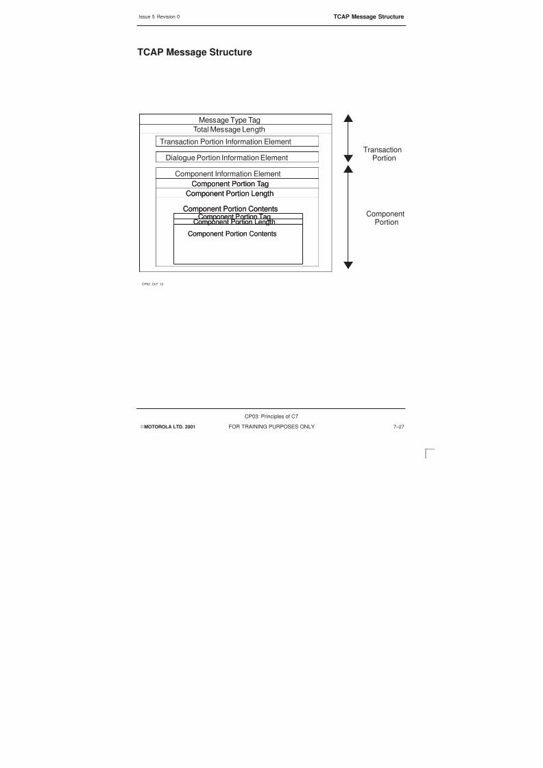
8/4/2019 C7 Principles
http://slidepdf.com/reader/full/c7-principles 263/298
Issue 5 Revision 0 TCAP Message Structure
EMOTOROLA LTD. 2001
CP03: Principles of C7
FOR TRAINING PURPOSES ONLY 7–27
TCAP Message Structure
CP03_Ch7_13
Total Message Length
Message Type Tag
TransactionPortion
ComponentPortion
Transaction Portion Information Element
Dialogue Portion Information Element
Component Portion Tag
Component Portion Length
Component Portion Contents
Component Portion Tag
Component Portion Length
Component Portion Contents
Component Information Element
Component Portion Tag
Component Portion Length
Component Portion Contents
Component Portion Tag
Component Portion Length
Component Portion Contents

8/4/2019 C7 Principles
http://slidepdf.com/reader/full/c7-principles 264/298
Issue 5 Revision 0TCAP Transaction Procedures
EMOTOROLA LTD. 2001
CP03: Principles of C7
FOR TRAINING PURPOSES ONLY7–28
TCAP Transaction Procedures
The operation of TCAP is logical.
The originating TC user will send a dialogue request (this is a BEG message – BEGin)
for TCAP to open a dialogue for one user with another. The BEG message comprises ofthe transaction ID and identifies a dialogue within the transaction layer.
The second TC user will either send a CON (CONtinue) or END message. If it is a CONmessage it means that the transport of information may take place. The first CONmessage confirms that the requested protocol and application context are accepted. Ifthe message is an END it means that the process is to be terminated.
The only other message is the ABT (AborT) message and this can be sent by either TCuser and the reason for termination does not need to be provided. There is, however adistinction between the user abort, U-ABT and the service provider abort, P-ABT.

8/4/2019 C7 Principles
http://slidepdf.com/reader/full/c7-principles 265/298
Issue 5 Revision 0 TCAP Transaction Procedures
EMOTOROLA LTD. 2001
CP03: Principles of C7
FOR TRAINING PURPOSES ONLY 7–29
TCAP transaction Procedures
CP03_Ch7_14
BEGIN [OTID = x, Invoke (#1, provide dialled freephone number)]
CONTINUE [OTID = y DTID = x,
Invoke(#2, play announcement and collect digits)]
CONTINUE [OTID = x DTID = y,
Return result (#2 collected digits)}
END [DTID = x, Return result (#1, routing number)]
ORIGINATING
EXCHANGEDATABASE
BEGIN [OTID = x, Invoke (#1, provide dialled freephone number)]
CONTINUE [OTID = y DTID = x,
Invoke(#2, play announcement and collect digits)]
CONTINUE [OTID = x DTID = y,
Return result (#2 collected digits)}
END [DTID = x, Return result (#1, routing number)]
ORIGINATING
EXCHANGEDATABASE

8/4/2019 C7 Principles
http://slidepdf.com/reader/full/c7-principles 266/298
Issue 5 Revision 0MAP user Communication
EMOTOROLA LTD. 2001
CP03: Principles of C7
FOR TRAINING PURPOSES ONLY7–30
MAP user Communication
As can be seen, all of the Application Parts interact using primitives. A primitive is acommunication between layers.
Service primitives are data units, or functional signals that are sent between adjacentlayers in order to invoke different procedures. The data units contain parameters withinformation that is used in the interaction between the two users.
TCAP primitives contain the portions of information that make up a TCAP message
Primitives can be sent in both directions
The virtual communication is the apparent communication that is seen by the user.
Primitives are used to access the different layers and levels. This is done through accesspoints and each layer has its own service access point. A service access point is anentry/exit point between two protocols and each service access point has a designatedfunction.

8/4/2019 C7 Principles
http://slidepdf.com/reader/full/c7-principles 267/298
Issue 5 Revision 0 MAP user Communication
EMOTOROLA LTD. 2001
CP03: Principles of C7
FOR TRAINING PURPOSES ONLY 7–31
MAP user Communication
CP03_Ch7_15
MAP
TCAP
MAP User
MAP
TCAP
MAP User
MAP ServicePrimitives
Primitives
Virtual Peer to Peercommunication
To/From SCCP To/From SCCP
Virtual Peer to Peercommunication
MAP ServicePrimitives
Primitives
PrimitivesPrimitives
MAP
TCAP
MAP User
MAP
TCAP
MAP User
MAP ServicePrimitives
Primitives
Virtual Peer to Peercommunication
To/From SCCP To/From SCCP
Virtual Peer to Peercommunication
MAP ServicePrimitives
Primitives
PrimitivesPrimitives

8/4/2019 C7 Principles
http://slidepdf.com/reader/full/c7-principles 268/298
Issue 5 Revision 0TCAP/MAP Transactions
EMOTOROLA LTD. 2001
CP03: Principles of C7
FOR TRAINING PURPOSES ONLY7–32
TCAP/MAP Transactions
In MAP there is an important need for the direction of the services to be known. Thereare four variants defined for every MAP service.
Initiating MAP user will start with a request (REQ), this translates itself as an indication(IND) at the responding MAP user.
When the responding MAP user replies the MAP service will respond with the response(RSP). This indicates that the message being sent, although known that it is leaving theresponding MAP user, it is in response to an already sent REQ. The RSP when it isreceived at the initiating MAP user it translated to a Confirmation (CNF) message.
These actions are important to understand the operation of direction control in MAP.

8/4/2019 C7 Principles
http://slidepdf.com/reader/full/c7-principles 269/298
Issue 5 Revision 0 TCAP/MAP Transactions
EMOTOROLA LTD. 2001
CP03: Principles of C7
FOR TRAINING PURPOSES ONLY 7–33
TCAP/MAP transactions
CP03_Ch7_16
Initiating MAP User Responding MAP User
Initiating MAP User Responding MAP User
Confirmation
CNF
Request
REQ
Indication
IND
Response
RES
APDU Transfer
MAP MAP
Addressing
Information
Addressing
Information
APDU Transfer
TCAP Transaction Sublayer
TCAP ComponentSublayer
TCAP Transaction Sublayer
TCAP ComponentSublayer
To/From SCCP To/From SCCP
Confirmation
CNF
Request
REQ
Indication
IND
Response
RES
Confirmation
CNF
Request
REQ
Indication
IND
Response
RES
APDU Transfer
MAP MAP
Addressing
Information
Addressing
Information
APDU Transfer
TCAP Transaction Sublayer
TCAP ComponentSublayer
TCAP Transaction Sublayer
TCAP ComponentSublayer
To/From SCCP To/From SCCP
APDU Transfer
MAP MAP
Addressing
Information
Addressing
Information
APDU Transfer
TCAP Transaction Sublayer
TCAP ComponentSublayer
TCAP Transaction Sublayer
TCAP ComponentSublayer
To/From SCCP To/From SCCP
TCAP Transaction Sublayer
TCAP ComponentSublayer
TCAP Transaction Sublayer
TCAP ComponentSublayer
To/From SCCP To/From SCCP

8/4/2019 C7 Principles
http://slidepdf.com/reader/full/c7-principles 270/298
Issue 5 Revision 0TCAP/MAP Transactions
EMOTOROLA LTD. 2001
CP03: Principles of C7
FOR TRAINING PURPOSES ONLY7–34

8/4/2019 C7 Principles
http://slidepdf.com/reader/full/c7-principles 271/298
EMOTOROLA LTD. 2001
CP03: Principles of C7
FOR TRAINING PURPOSES ONLY i
Chapter 8
GSM Network Overview to SS7

8/4/2019 C7 Principles
http://slidepdf.com/reader/full/c7-principles 272/298
Issue 5 Revision 0
EMOTOROLA LTD. 2001
CP03: Principles of C7
FOR TRAINING PURPOSES ONLYii

8/4/2019 C7 Principles
http://slidepdf.com/reader/full/c7-principles 273/298
Issue 5 Revision 0
EMOTOROLA LTD. 2001
CP03: Principles of C7
FOR TRAINING PURPOSES ONLY iii
Chapter 8GSM Network Overview to SS7 i. . . . . . . . . . . . . . . . . . . . . . . . . . . . . . . . . . . . . .
Objectives 8–1. . . . . . . . . . . . . . . . . . . . . . . . . . . . . . . . . . . . . . . . . . . . . . . . . . . . . . . . . . . . . . . . .
GSM Network Components 8–2. . . . . . . . . . . . . . . . . . . . . . . . . . . . . . . . . . . . . . . . . . . . . . . . . .
GSM Interface Names 8–4. . . . . . . . . . . . . . . . . . . . . . . . . . . . . . . . . . . . . . . . . . . . . . . . . . . . . . .
Interface Names 8–4. . . . . . . . . . . . . . . . . . . . . . . . . . . . . . . . . . . . . . . . . . . . . . . . . . . . . .
A Interface Protocols 8–6. . . . . . . . . . . . . . . . . . . . . . . . . . . . . . . . . . . . . . . . . . . . . . . . . . . . . . . .
A Interface between MSC and BSS 8–8. . . . . . . . . . . . . . . . . . . . . . . . . . . . . . . . . . . . . . . . . . .
BSSAP Message Structure 8–10. . . . . . . . . . . . . . . . . . . . . . . . . . . . . . . . . . . . . . . . . . . . . . . . . .
BSSMAP Message 8–10. . . . . . . . . . . . . . . . . . . . . . . . . . . . . . . . . . . . . . . . . . . . . . . . . . . .
DTAP Message 8–10. . . . . . . . . . . . . . . . . . . . . . . . . . . . . . . . . . . . . . . . . . . . . . . . . . . . . . .
Interfaces Between BSC, BTS and MS 8–12. . . . . . . . . . . . . . . . . . . . . . . . . . . . . . . . . . . . . . . .
LAPD frame Structure 8–14. . . . . . . . . . . . . . . . . . . . . . . . . . . . . . . . . . . . . . . . . . . . . . . . . . . . . . .
Address Field 8–14. . . . . . . . . . . . . . . . . . . . . . . . . . . . . . . . . . . . . . . . . . . . . . . . . . . . . . . . .
Control field 8–14. . . . . . . . . . . . . . . . . . . . . . . . . . . . . . . . . . . . . . . . . . . . . . . . . . . . . . . . . .
LAPDm Frames 8–16. . . . . . . . . . . . . . . . . . . . . . . . . . . . . . . . . . . . . . . . . . . . . . . . . . . . . . . . . . . .
LAPDm Frame Structure 8–18. . . . . . . . . . . . . . . . . . . . . . . . . . . . . . . . . . . . . . . . . . . . . . . . . . . . .
A and B format Frame Structure 8–20. . . . . . . . . . . . . . . . . . . . . . . . . . . . . . . . . . . . . . . . . . . . . .
Address Field 8–20. . . . . . . . . . . . . . . . . . . . . . . . . . . . . . . . . . . . . . . . . . . . . . . . . . . . . . . . .
Control Field 8–20. . . . . . . . . . . . . . . . . . . . . . . . . . . . . . . . . . . . . . . . . . . . . . . . . . . . . . . . . .
SS7 Connection to GPRS 8–22. . . . . . . . . . . . . . . . . . . . . . . . . . . . . . . . . . . . . . . . . . . . . . . . . . . .

8/4/2019 C7 Principles
http://slidepdf.com/reader/full/c7-principles 274/298
Issue 5 Revision 0
EMOTOROLA LTD. 2001
CP03: Principles of C7
FOR TRAINING PURPOSES ONLYiv

8/4/2019 C7 Principles
http://slidepdf.com/reader/full/c7-principles 275/298
Issue 5 Revision 0 Objectives
EMOTOROLA LTD. 2001
CP03: Principles of C7
FOR TRAINING PURPOSES ONLY 8–1
Objectives
At the end of this chapter the student will be able to:
S Identify the two Subsystems and their components in GSM.
S Identify the components and interfaces of the GSM network and describe theirfunction.
S Understand the A interface, LApD and LApdM message formats.

8/4/2019 C7 Principles
http://slidepdf.com/reader/full/c7-principles 276/298
Issue 5 Revision 0GSM Network Components
EMOTOROLA LTD. 2001
CP03: Principles of C7
FOR TRAINING PURPOSES ONLY8–2
GSM Network Components
Each network component is illustrated only once, however, many of the components willoccur several times throughout a network.
Each network component is designed to communicate over an interface specified by theGSM standards. This provides flexibility and enables a network provider to utilize systemcomponents from different manufacturers. For example Motorola Base Station System(BSS) equipment may be coupled with an Ericsson Network Switching System.
The principle component groups of a GSM network are:
The Mobile Station (MS)
This consists of the mobile telephone, fax machine etc. This is the part of the networkthat the subscriber will see.
The Base Station System (BSS)
This is the part of the network that provides the radio interconnection from the MS to theland-based switching equipment.
The Network Switching System
This consists of the Mobile services Switching Centre (MSC) and its associatedsystem-control databases and processors together with the required interfaces. This isthe part that provides for interconnection between the GSM network and the PublicSwitched Telephone Network (PSTN).
The Operations and Maintenance System
This enables the network provider to configure and maintain the network from a central
location.

8/4/2019 C7 Principles
http://slidepdf.com/reader/full/c7-principles 277/298
Issue 5 Revision 0 GSM Network Components
EMOTOROLA LTD. 2001
CP03: Principles of C7
FOR TRAINING PURPOSES ONLY 8–3
GSM Network Components
CP03_Ch8_01
NMC
OMC
Operations and
Maintenance SystemNetwork Switching System
Base Station System
Interface/Connection
Mobile Station
PSTN
VLR HLR
AUC
EIRMSC
IWFEC
BTS
BSC
ME
SIM
XCDR

8/4/2019 C7 Principles
http://slidepdf.com/reader/full/c7-principles 278/298
Issue 5 Revision 0GSM Interface Names
EMOTOROLA LTD. 2001
CP03: Principles of C7
FOR TRAINING PURPOSES ONLY8–4
GSM Interface Names
Interface Names
Each interface specified within the GSM system has a name associated with it. Thediagram opposite illustrates the names of all the interfaces specified by GSM.
Air-interface MS-BTS
A-bis(Mo-bis) BTS-BSC
A-interface BSS-MSC
B-Interface MSC-VLR
C-interface MSC-HLR
D-interface HLR-VLR
E-interface inter-MSC
F-interface MSC-EIR
G-interface VLR-VLR
R-interface MS-DTE (Data Terminating Equipment)

8/4/2019 C7 Principles
http://slidepdf.com/reader/full/c7-principles 279/298
Issue 5 Revision 0 GSM Interface Names
EMOTOROLA LTD. 2001
CP03: Principles of C7
FOR TRAINING PURPOSES ONLY 8–5
GSM Interface Names
CP03_Ch8_02
NMC
OMC
VLR
MSC
ECIWFXC
XC
VLR
EC IWF XC
MSC
HLR
AUC
EIR
PSTN
BTS BSC
CO–LOCATED ENTITIES
BSS
BTS
BTS
BTS
BTS
BTS
BTS
BSC
BTS BTS BTS
MS
MS
MS
VLR
A
E
Abis
Um
G
B
D
BC
H
F

8/4/2019 C7 Principles
http://slidepdf.com/reader/full/c7-principles 280/298
Issue 5 Revision 0A Interface Protocols
EMOTOROLA LTD. 2001
CP03: Principles of C7
FOR TRAINING PURPOSES ONLY8–6
A Interface Protocols
The A interface is the interface between the BSS and the MSC. The protocol usedacross the A interface is called Base Station System Application Part (BSSAP). TheBSSAP sends messages associated with specific MS in the SCCP connection-orientated
mode.
The BSSAP is used for signalling between MSC and BSS and it is made up of threetypes of signalling messages
S DTAP
S BSSMAP
S Initial MS message
DTAP and Initial signalling can be looked at as one as they are both transparent to theBSS, both of these messages carry user information.

8/4/2019 C7 Principles
http://slidepdf.com/reader/full/c7-principles 281/298
Issue 5 Revision 0 A Interface Protocols
EMOTOROLA LTD. 2001
CP03: Principles of C7
FOR TRAINING PURPOSES ONLY 8–7
A Interface Protocols
CP03_Ch8_03
DTAP
MTPLevel 1
MTPLevel 2
MTPLevel 3
SCCP
BSSMAP
BSSAP
DTAP
MTPLevel 1
MTPLevel 2
MTPLevel 3
SCCP
BSSMAP
BSSAP
M
SC
BSS
BSC/BTS
Transparent to BSS
DTAP
BSSAP LAPDm
Initial MS
M
SC
BSS
BSC/BTS
Transparent to BSS
DTAP
BSSAP LAPDm
Initial MS

8/4/2019 C7 Principles
http://slidepdf.com/reader/full/c7-principles 282/298
Issue 5 Revision 0A Interface between MSC and BSS
EMOTOROLA LTD. 2001
CP03: Principles of C7
FOR TRAINING PURPOSES ONLY8–8
A Interface between MSC and BSS
The signalling channel between the MSC and BSS is able to serve one or more basetransceiver stations. Motorola’s feature is 100 BTSs supported by one BSC.
The protocols used for signalling between the MSC and BSS are BSSAP, SCCP andMTP.
The distribution sub layer performs the distribution of BSSAP messages to eitherBSSMAP or DTAP. It is able to do this by reading the distribution data unit which iscontained in the header of the message. This information is used to determine if themessage is BSSMAP or DTAP.

8/4/2019 C7 Principles
http://slidepdf.com/reader/full/c7-principles 283/298
Issue 5 Revision 0 A Interface between MSC and BSS
EMOTOROLA LTD. 2001
CP03: Principles of C7
FOR TRAINING PURPOSES ONLY 8–9
A Interface between MSC and BSS
CP03_Ch8_04
MTP
SCCP
Distribution Sublayer
BSSAP
MTP
SCCP
Distribution Sublayer
BSSAP
MTP
SCCP
Distribution Sublayer
BSSAP
MTP
SCCP
Distribution Sublayer
MTP
SCCP
Distribution Sublayer
BSSAP
DTAPBSSMAP
DTAPBSSMAP DTAPBSSMAP
DTAPBSSMAP
A–Interface
MSC BSS
A–Interface
MSC BSS

8/4/2019 C7 Principles
http://slidepdf.com/reader/full/c7-principles 284/298
Issue 5 Revision 0BSSAP Message Structure
EMOTOROLA LTD. 2001
CP03: Principles of C7
FOR TRAINING PURPOSES ONLY8–10
BSSAP Message Structure
The entire BSSAP message is embedded in an SCCP message. The first 8 or 16 bits ofthe BSSAP indicate if the message is either a BSSMAP or a DTAP. This is thediscrimination field.
BSSMAP, the 8-bit header discriminates the message as a BSSMAP.
DTAP, the 16 bits break into the first 8 bits indicate a DTAP and the second 8 bitsindicate the data link connection identifier (DLCI).
A length indicator, indicates the length of the information/data field.
BSSMAPMessage
Message type is an 8-bit field indicating the code of the message.
Information field consists of the information element identifier (IEI), a length indicator anda data field.
DTAP Message
Data Link Connection Identification (DLCI), part of the distribution data unit, is used toidentify the radio channel and also specifies which SAPI value used on the radio link:
S SAPI 0= call control signalling
S SAPI 1= short message service
Message type is an 8-bit field indicating the code of the message
TI/PD
The purpose of Transaction Identifier (TI) is to distinguish between multiple parallelactivities within one MS.
Protocol Discriminator (PD) is to distinguish between messages belonging to following:
S Call control
S Mobility management
S Radio resource management
S Supplementary service control
S Other signalling procedures
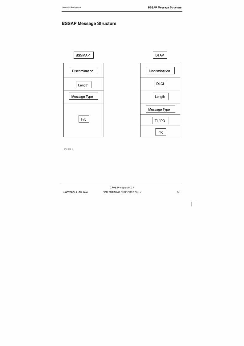
8/4/2019 C7 Principles
http://slidepdf.com/reader/full/c7-principles 285/298
Issue 5 Revision 0 BSSAP Message Structure
EMOTOROLA LTD. 2001
CP03: Principles of C7
FOR TRAINING PURPOSES ONLY 8–11
BSSAP Message Structure
CP03_Ch8_05
BSSMAP
Discrimination
Length
Message Type
Info
BSSMAP
Discrimination
Length
Message Type
Info
DTAP
Discrimination
Length
Message Type
Info
DLCI
TI / PD
DTAP
Discrimination
Length
Message Type
Info
DLCI
TI / PD

8/4/2019 C7 Principles
http://slidepdf.com/reader/full/c7-principles 286/298
Issue 5 Revision 0Interfaces Between BSC, BTS and MS
EMOTOROLA LTD. 2001
CP03: Principles of C7
FOR TRAINING PURPOSES ONLY8–12
Interfaces Between BSC, BTS and MS
Between the BSC and the BTS one 64 kbit/sec channel is used for sending all thesignalling information. This requires a special protocol and this is the link accessprocedure on D channel (LAPD).
The sending portion constructs a LAPD frame, which is then transmitted octet by octetover the PCM link. At the receiving end the octets are put back into the LAPD frame andthe information data is extracted and then delivered to the user.
LAPD supports both unacknowledged and acknowledged information transfer.
Between the BTS and the MS which is the Air interface, it is not possible to use TDMA tosend a signalling frame that is the length of LAPD. As a result the message needs to bedivided into segments. To meet the radio requirements the LAPD functionality has beenused to create the LAPDm.
LAPD and LAPDm are Layer 2 in the OSI protocol Stack.

8/4/2019 C7 Principles
http://slidepdf.com/reader/full/c7-principles 287/298
Issue 5 Revision 0 Interfaces Between BSC, BTS and MS
EMOTOROLA LTD. 2001
CP03: Principles of C7
FOR TRAINING PURPOSES ONLY 8–13
Interfaces Between BSC, BTS and MS
Between the BSC and the BTS the protocol for transporting signalling
messages is Link Access Procedure on D–channel (LAPD)
Between the BTS and the MS, which is viewed as the air interface, a
modified LAPD protocol is used. (LAPDm). This protocol is based onLAPD functionality but has been adapted to match radio requirements.
Due to the length of LAPD frame, sending the frame over the air interface
requires that frame to be segmented.
S
S
CP03_Ch8_06
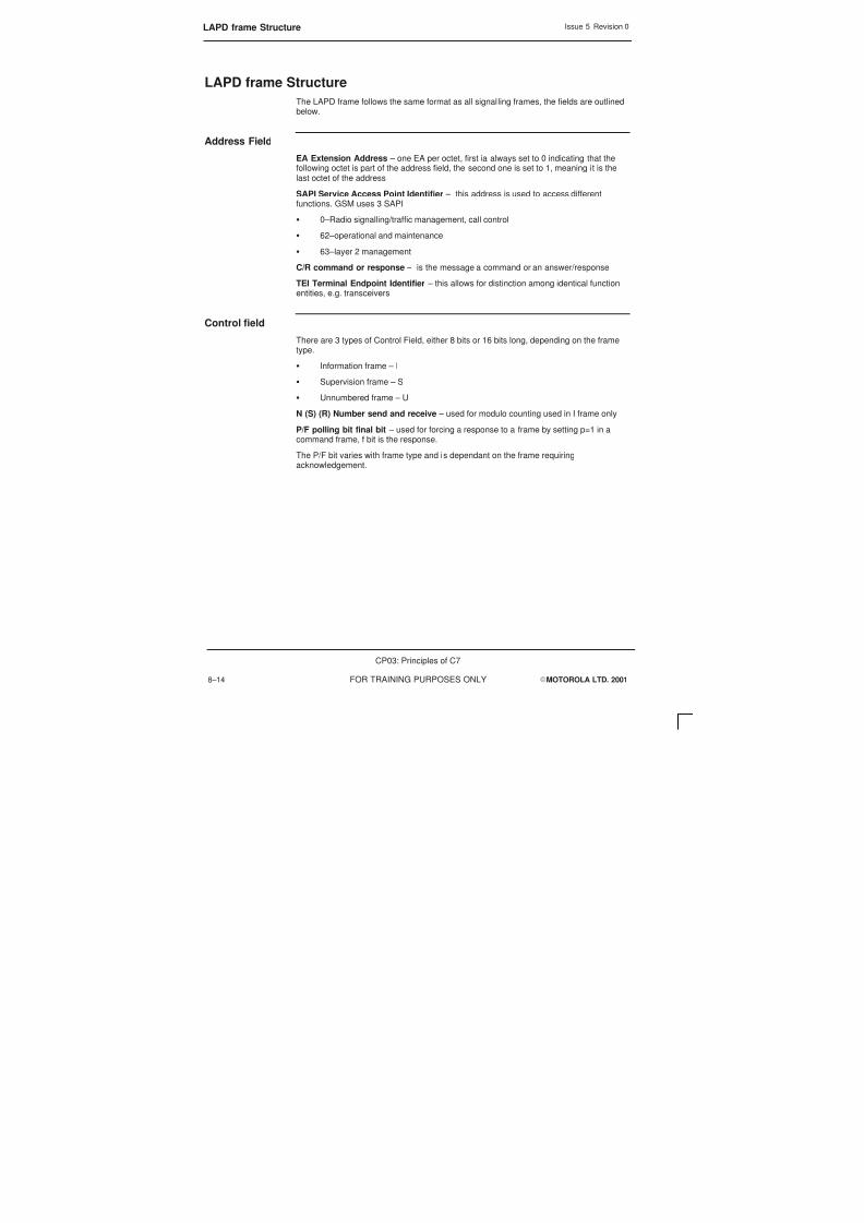
8/4/2019 C7 Principles
http://slidepdf.com/reader/full/c7-principles 288/298
Issue 5 Revision 0LAPD frame Structure
EMOTOROLA LTD. 2001
CP03: Principles of C7
FOR TRAINING PURPOSES ONLY8–14
LAPD frame Structure
The LAPD frame follows the same format as all signalling frames, the fields are outlinedbelow.
Address Field
EA Extension Address – one EA per octet, first ia always set to 0 indicating that thefollowing octet is part of the address field, the second one is set to 1, meaning it is thelast octet of the address
SAPI Service Access Point Identifier – this address is used to access differentfunctions. GSM uses 3 SAPI
S 0–Radio signalling/traffic management, call control
S 62–operational and maintenance
S 63–layer 2 management
C/R command or response – is the message a command or an answer/response
TEI Terminal Endpoint Identifier – this allows for distinction among identical functionentities, e.g. transceivers
Control field
There are 3 types of Control Field, either 8 bits or 16 bits long, depending on the frametype.
S Information frame – I
S Supervision frame – S
S Unnumbered frame – U
N (S) (R) Number send and receive – used for modulo counting used in I frame only
P/F polling bit final bit – used for forcing a response to a frame by setting p=1 in acommand frame, f bit is the response.
The P/F bit varies with frame type and is dependant on the frame requiringacknowledgement.

8/4/2019 C7 Principles
http://slidepdf.com/reader/full/c7-principles 289/298
Issue 5 Revision 0 LAPD frame Structure
EMOTOROLA LTD. 2001
CP03: Principles of C7
FOR TRAINING PURPOSES ONLY 8–15
LAPD Frame Structure
CP03_Ch8_07
C/RTEI SAPIEA EAC/RTEI SAPIEA EA
FirstTransmission DirectionLast FirstTransmission DirectionLast
Flag FlagFCSInformation field
Layer 3Control Address
8 816 0–260 octets 16 16
Flag FlagFCSInformation field
Layer 3Control Address
Flag FlagFCSInformation field
Layer 3Control Address
8 816 0–260 octets 16 16
N(S)PFN(R) 0N(S)PFN(R) 0N(S)PFN(R) 0

8/4/2019 C7 Principles
http://slidepdf.com/reader/full/c7-principles 290/298
Issue 5 Revision 0LAPDm Frames
EMOTOROLA LTD. 2001
CP03: Principles of C7
FOR TRAINING PURPOSES ONLY8–16
LAPDm Frames
There are two operation modes in LAPDm
Unacknowledged
Messages that do not need to be acknowledged are sent in Unnumbered Informationframes (UI), there is no error correction or flow control for these frames.
Acknowledged
These are sent when it is necessary to obtain an answer. The frame is a NumberedInformation Frame (I-frame). They require acknowledgement before the next frame issent.
There are three formats of the LAPDm frame:
S A-format
SB-format
S Bbis format
A and B formats are used in both directions. Bbis format is used in downlink only.

8/4/2019 C7 Principles
http://slidepdf.com/reader/full/c7-principles 291/298
Issue 5 Revision 0 LAPDm Frames
EMOTOROLA LTD. 2001
CP03: Principles of C7
FOR TRAINING PURPOSES ONLY 8–17
LAPDm Frames
CP03_Ch8_08
There are two type of frame, Unacknowledged (UI) and Acknowledged
and three formats for the LAPDm frame, which one is sent depends on
the type of information to be sent
– A–format, sent with no payload but has addressing information
– B–format, used to transport signalling information
– Bbis–format, used for broadcast when no addressing information is
needed
– All formats are of identical length 23 octets
S

8/4/2019 C7 Principles
http://slidepdf.com/reader/full/c7-principles 292/298
Issue 5 Revision 0LAPDm Frame Structure
EMOTOROLA LTD. 2001
CP03: Principles of C7
FOR TRAINING PURPOSES ONLY8–18
LAPDm Frame Structure
The three frame types that are used can be separated into two frame structures – theA-format and B-format can be viewed as the same format and the Bbis format isdifferent.
The Bbis format is the easiest structure to view. It consists of an information field, whichis the signalling data which takes the frame length to 23 octets.
The A-format and B-format frame length sub field contains more information.
EL Extension Length bit, is always set to 0 unless another length indicator field followswhen it is set to 1.
M More data bit this bit indicates segmentation if the layer 3 message.
S M=1 part of a segmented message
S M=0 last segment of message
The last bits 2–7 are used in all three frames to indicate the length of the information
field.

8/4/2019 C7 Principles
http://slidepdf.com/reader/full/c7-principles 293/298
Issue 5 Revision 0 LAPDm Frame Structure
EMOTOROLA LTD. 2001
CP03: Principles of C7
FOR TRAINING PURPOSES ONLY 8–19
LAPDm Frame Structure
CP03_Ch8_09
Bbis format
Signalling Data
Bbis format
Signalling Data
B–format
Fill–in octet Signalling Data Frame Length Control Field Address FieldFill–in octet Signalling Data Frame Length Control Field Address Field
Fill octets Frame Length Control Field Address FieldFill octets Frame Length Control Field Address Field
A–format
Length MLengthLength M EL

8/4/2019 C7 Principles
http://slidepdf.com/reader/full/c7-principles 294/298
Issue 5 Revision 0A and B format Frame Structure
EMOTOROLA LTD. 2001
CP03: Principles of C7
FOR TRAINING PURPOSES ONLY8–20
A and B format Frame Structure
The A-format and B-format have the same structure – the only difference being after theframe length sub field.
Address Field
EA Extension Address – one EA per octet, the first EA is permanently set to 0indicating following octet is part of the address field.
C/R command or response – is the message a command or an answer/response.
SAPI Service Access Point Identifier – this address is used to access differentfunctions. LAPDm uses different SAPI on the air interface.
S SAPI 0= Radio Resources, Mobility Management, Call Control.
S SAPI 3= Short Message Service, Supplementary Services.
LPD Link Protocol Discriminator – a 2-bit field always coded 00, unless Cell Broadcastservice is used then it is coded 01.
X is a fill bit.
Control Field
The MT message Type bit – indicates what the frame is being used for,
S 0 = Information Frame
S 1 = Supervisory frame
In unnumbered frames the N(S) field is not used and becomes part of the MT field, the
MT field then is a 2bit field.
11 = Unnumbered frame.
N (S) (R) Number send and receive – used for modulo counting used in I frame only.
P/F polling bit final bit – used for forcing a response to a frame by setting p=1 in acommand frame, f bit is the response.
The P/F bit varies with frame type and is dependant on the frame requiringacknowledgement.
In the B-format, if the information to be transmitted requires less space than thesignalling data field, the space is filled in with fill-in octets.

8/4/2019 C7 Principles
http://slidepdf.com/reader/full/c7-principles 295/298
Issue 5 Revision 0 A and B format Frame Structure
EMOTOROLA LTD. 2001
CP03: Principles of C7
FOR TRAINING PURPOSES ONLY 8–21
A and B format Frame Structure
CP03_Ch8_10
B–format
Fill–in octet Signalling Data Frame Length Control Field Address FieldFill–in octet Signalling Data Frame Length Control Field Address Field
Fill octets Frame Length Control Field Address FieldFill octets Frame Length Control Field Address Field
A–format
N(S)P/FN(R) MTN(S)P/FN(R)
MTN(S)P/FN(R)
MT
SAPIX C/RLPD EASAPIX C/RLPD EASAPIX C/RLPD EA

8/4/2019 C7 Principles
http://slidepdf.com/reader/full/c7-principles 296/298
Issue 5 Revision 0SS7 Connection to GPRS
EMOTOROLA LTD. 2001
CP03: Principles of C7
FOR TRAINING PURPOSES ONLY8–22
SS7 Connection to GPRS
GPRS is a new set of GSM bearer services that provide packet mode transmission withinthe PLMN.
There remains a requirement to interface with certain components within the GSMnetwork over SS7 interfaces.
The interfaces that are used are:
Gs – the interface between the MSC/VLR and the SGSN
Gr – the interface between the SGSN and the HLR.
The Gs is the interface that is used to establish what state the subscriber is in – if thesubscriber has initialised the GPRS services or not (IMSI attached). The Gs is also usedfor circuit switching paging messages.
The Gr is the interface that is used to establish if the subscriber has the servicesenabled.

8/4/2019 C7 Principles
http://slidepdf.com/reader/full/c7-principles 297/298
Issue 5 Revision 0 SS7 Connection to GPRS
EMOTOROLA LTD. 2001
CP03: Principles of C7
FOR TRAINING PURPOSES ONLY 8–23
SS7 Connections to GPRS
CP03_Ch8_11
ExternalGateway
IP Routers
GatewayIP Router
GatewayGSN
Comm Hub ISS
SF
Serving GSN
FRaccess
BSC
PCU
BTS
MSC – VLRs
SMS – SC
SS7Network
SignalingTransferPoints
HLRs
Gr Gs Gd
Gn
FR access
Frame RelayNetwork
IPhost
IPhost
IPhost
IPhost IP
host
IPhostIP
hostExternal IP Network
ExternalGateway
IP Routers
GatewayIP Router
GatewayGSN
Serving GSN
FRaccess
FR access
MSMSMSMSMSMSMSMSMSMSMSMS
MSMSMSMSMSMSMSMSMSMS
Gn
Gn Gn
Gi Gi
BSC
PCU
BTS
BSC
PCU
BTS
BSC
PCU
BTS
cell
External IP Network External IP Network
MS

8/4/2019 C7 Principles
http://slidepdf.com/reader/full/c7-principles 298/298
Issue 5 Revision 0SS7 Connection to GPRS

![大垣市 · ˝˛12345 m¿ /À c7k c7` ´ˆ ˜~ ¯˘ ˙¨ c7 ŠÉ ˚¸c7 RS \] ¯˘Ì˝k ˛ˇ— CÑHYˇ IGÑIB ˝kOÒ c7Ó $%& " Ì ÔGÕCBÔH c7 Ö×ØÙ ÚÛxz!fifl](https://img.dokumen.tips/doc/110x75/5f2dc1d5e628d06bd419b879/-12345-m-c7k-c7-oe-c7-c7-rs-oek.jpg)


![C7 graham session c7 mon1530_v6[2]](https://img.dokumen.tips/doc/110x75/58ed94c51a28ab717c8b475d/c7-graham-session-c7-mon1530v62.jpg)