Embed Size (px)
Citation preview

Structural Design
C5a
01 Load-bearing Concept 02 Typical Panel 03 Buckling Length 04 Load Calculations 05 Screw Connections 06 Reinforcements 07 Compression Strength 08 Braced Panel Calculation 09 Load-bearing Lintels 10 Aligning Panels Over Two Floors

© 2021
Load-bearing construction: wood
Only wooden construction is used for structural calculation.
» Any engineer used to wooden construction can calculate the load-bearing capacity based on Eurocode rules
106
© 2021
Typical panel construction
» A single post 45x95 mm in each corner supports the panel
» A non-load-bearing middle column is added if panel is wider than 80 cm
» When two panels are connected, a double post 90x95 mm is the result
» Every 100 cm there is a horizontal reinforcement against buckling of the posts
107

© 2021
Double load-bearing structure
The double load-bearing construction provides support for load on the inside as well as the outside posts
Note: » All example calculations are made
considering load on just one side!
108
© 2021
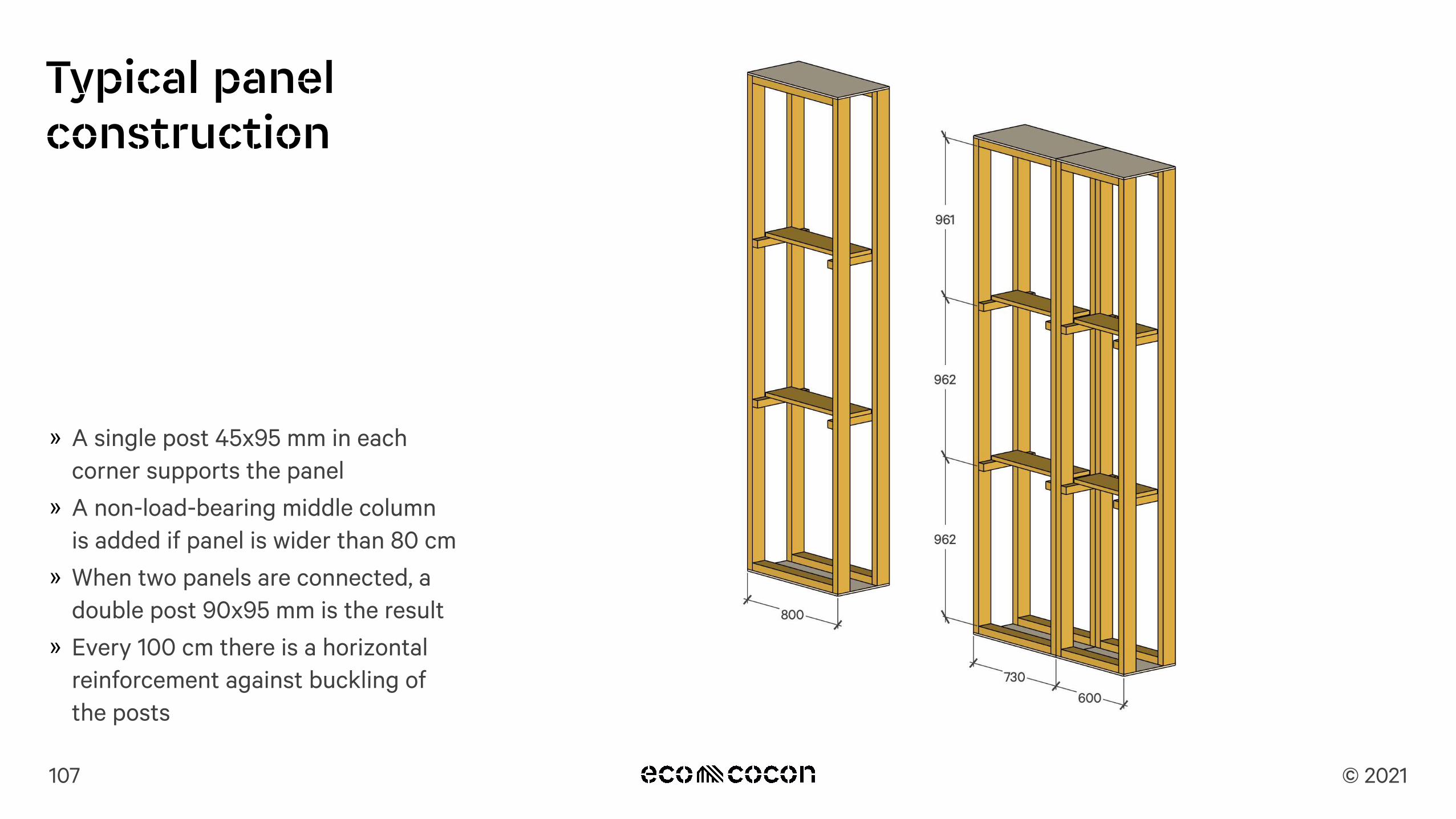
Horizontal reinforcements against buckling
» Regular horizontal reinforcements are added to minimize buckling length to max 1000 mm
» This is taken into account for the post and double post calculation
109
Reinforcements against buckling

© 2021
Single post
» A single 45x95 mm post protected against buckling every 288.6 cm (lx) can carry 11.524 kN
» A 45x95 mm post supported against buckling every 96.2 cm (ly) can carry 16.747 kN
Note » Strength of posts depend on buckling
length taken into consideration
Explained » 1 kN is the equivalent of 1000 N =
approx. load of 100 kg » 10 kN are approx. 1 ton = 1000 kg
110
11.524 kN for lx
16.747 kN for lyor

© 2021
Connecting two panels
111
∅8 mm
© 2021
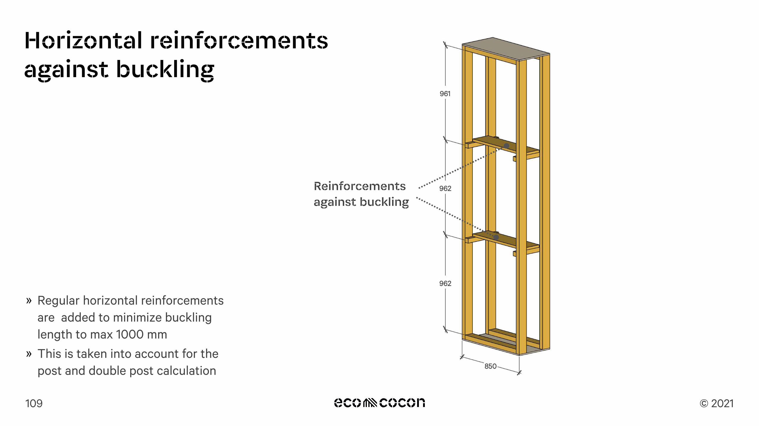
Double post
» A double 2x45x95 mm post that is protected against buckling every 288.6 cm (lx) can carry 23.048 kN
» A double 2x45x95 mm post supported against buckling every 96.2 cm (ly) can carry 55.767 kN
Note » Strength of post depends on buckling
length. If that is shorter, the load can be many times higher
112
55.767 kN for ly
23.048 kN for lxor

© 2021
Special element: column
» A single 45x95 mm post is reinforced with a 12 mm plywood
» There is a horizontal bar max. every 80 cm, protecting against buckling
» A single 45x95 mm post that is reinforced with a 12 mm plywood against buckling can carry 35.700 kN
Note » Used for short wall segments or for high
pointed loads.
113
35.700 kN

© 2021
Plywood reinforced opening
» Openings are reinforced with 18 mm plywood
» This significantly increases the load-bearing capacity
» A single 45x95 mm post that is reinforced with a 18 mm plywood can carry 36.184 kN
» Calculations are done case by case
114
36.184 kN

© 2021
Possible reinforcement: Narrower panels
» Using narrower panels brings the double posts closer to each other
» A construction with a double post every 60 cm can take 93 kN/m on
one side of the panels » Columns 40x40 cm can be used at
the end of the wall or in corners
115

© 2021
Possible reinforcement: Using columns
Using columns for every second panel adds a plywood layer between the panels. The buckling strength increases dramatically and the construction can take much larger loads.
Note » Plywood sheets can be also be added
separately between panels in the construction phase - it is not absolutely necessary to produce columns
116
112.563 kN
© 2021
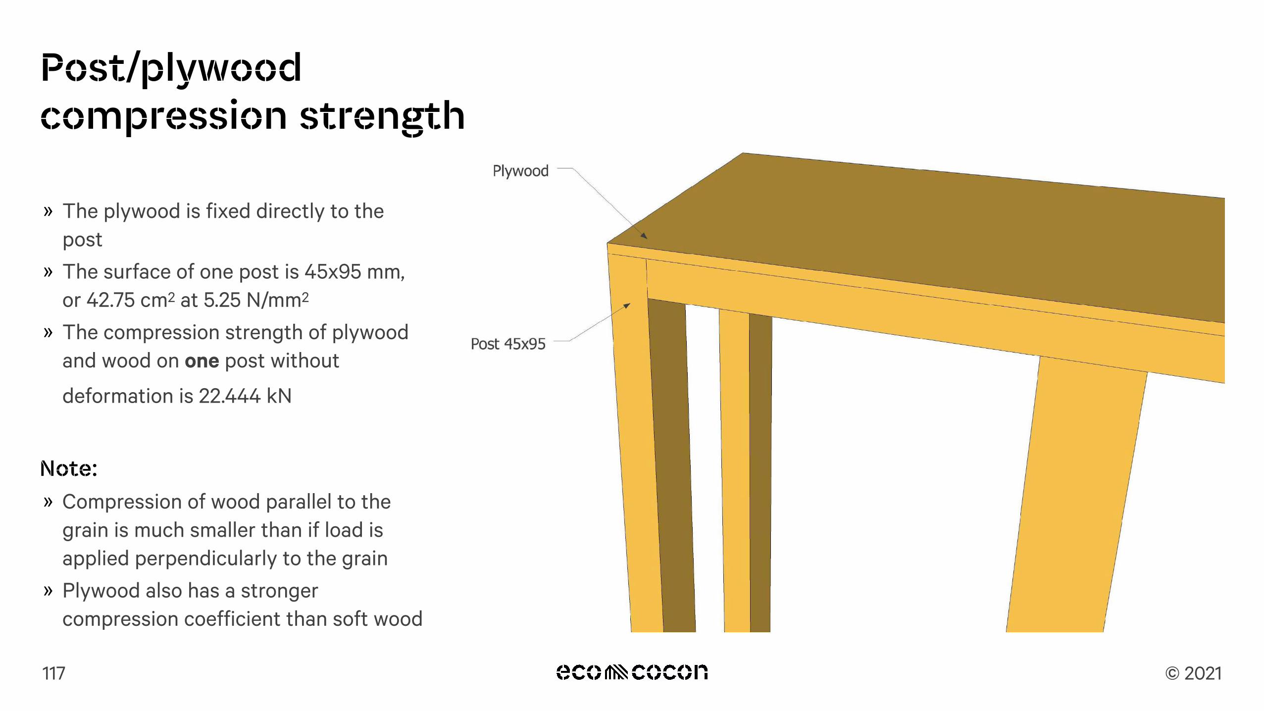
» The plywood is fixed directly to the post
» The surface of one post is 45x95 mm, or 42.75 cm2 at 5.25 N/mm2
» The compression strength of plywood and wood on one post without
deformation is 22.444 kN
Note: » Compression of wood parallel to the
grain is much smaller than if load is applied perpendicularly to the grain
» Plywood also has a stronger compression coefficient than soft wood
117
Post/plywood compression strength

© 2021
Ring beam compression strength» The ring beam placed on the posts / plywood
will also experience higher compression above posts areas
» The compression area for 1 post is 4 275 mm2 and 8550 mm2 respectively
» The wood in the ring beam is layered horizontally: the strength of the wood is weaker
» For soft wood like spruce the max. longterm load is 5.25 N/mm2
» The compression strength of plywood and wood on one post without deformation is 22.444 kN
» The compression strength of plywood and wood on a double post without deformation is 44.888
kN
Note » This compression will be decisive only for higher
buildings
118

© 2021
Special elements: Braced panels
» Braced panels are good to take lateral load in construction
» Usually two braced panels are used opposite each other
» These calculations will be done together with the Panel Project based on loading values given by the local engineer
119

© 2021
Braced panel calculations
Our engineer can verify with a separate calculation if the loads can be absorbed by the braced panels.
Note: » These calculations will be done together
with the panel project based on loading values given by the local engineer
120
Ecole Prilly project.Ecococon braced panel racking resistance.Braced panel height: ≔H 2.8 mBraced panel width: ≔B 0.8 mBracing angle: ≔α 61.7 deg
2
Factor for permanent actions: ≔γG 1.35Factor for variable actions: ≔γQ 1.50 3Permanent action
≔gk.i 56.4 ――kNm ≔gk.o 9.4 ――
kNm≔gd.i =⋅gk.i γG 76.14 ――
kNm ≔gd.o =⋅gk.o γG 12.69 ――
kNmVariable action of roof:
5≔qk.i 18.3 ――kNm ≔qk.o 5.4 ――
kNm≔qd.i =⋅qk.i γQ 27.45 ――
kNm ≔qd.o =⋅qk.o γQ 8.1 ――
kNmSum of roof actions: ≔p1.i =+gd.i qd.i 103.59 ――
kNm
≔p1.o =+gd.o qd.o 20.79 ――kNm
41
Loading on the top of panel: ≔Fvd.i =⋅p1.i B 82.872 kN Fig 1. Braced panel≔Fvd.o =⋅p1.o B 16.632 kN
Racking load on panel: ≔Fwd =⋅⋅15.51 kN γQ 0.5 11.633 kN
Reactions of panel: ≔Ry1.i =⋅⎛⎜⎝
−Fvd.i ―――⋅Fwd H
B
⎞⎟⎠−1 −42.158 kN ≔Ry2.i =+Fvd.i ―――
⋅Fwd HB
123.586 kN
≔Ry1.o =⋅⎛⎜⎝
−Fvd.o ―――⋅Fwd H
B
⎞⎟⎠−1 24.082 kN ≔Ry2.o =+Fvd.o ―――
⋅Fwd HB
57.346 kN≔Rx =Fwd 11.633 kNCompression of members:
≔N2_5 =―――Fwd
cos ⎛⎝α⎞⎠24.537 kN ≔N4_5 =max ⎛⎝ ,Ry2.i Ry2.o⎞⎠ 123.586 kN ≔NEd =max ⎛⎝ ,N2_5 N4_5⎞⎠ 123.586 kN

© 2021
Stress on screw connections
A separate calculation to verify the stress on the connecting screws can be made.
Note: » These calculations will be made
together with the panel project based on loading values given by the local engineer
121
© 2021
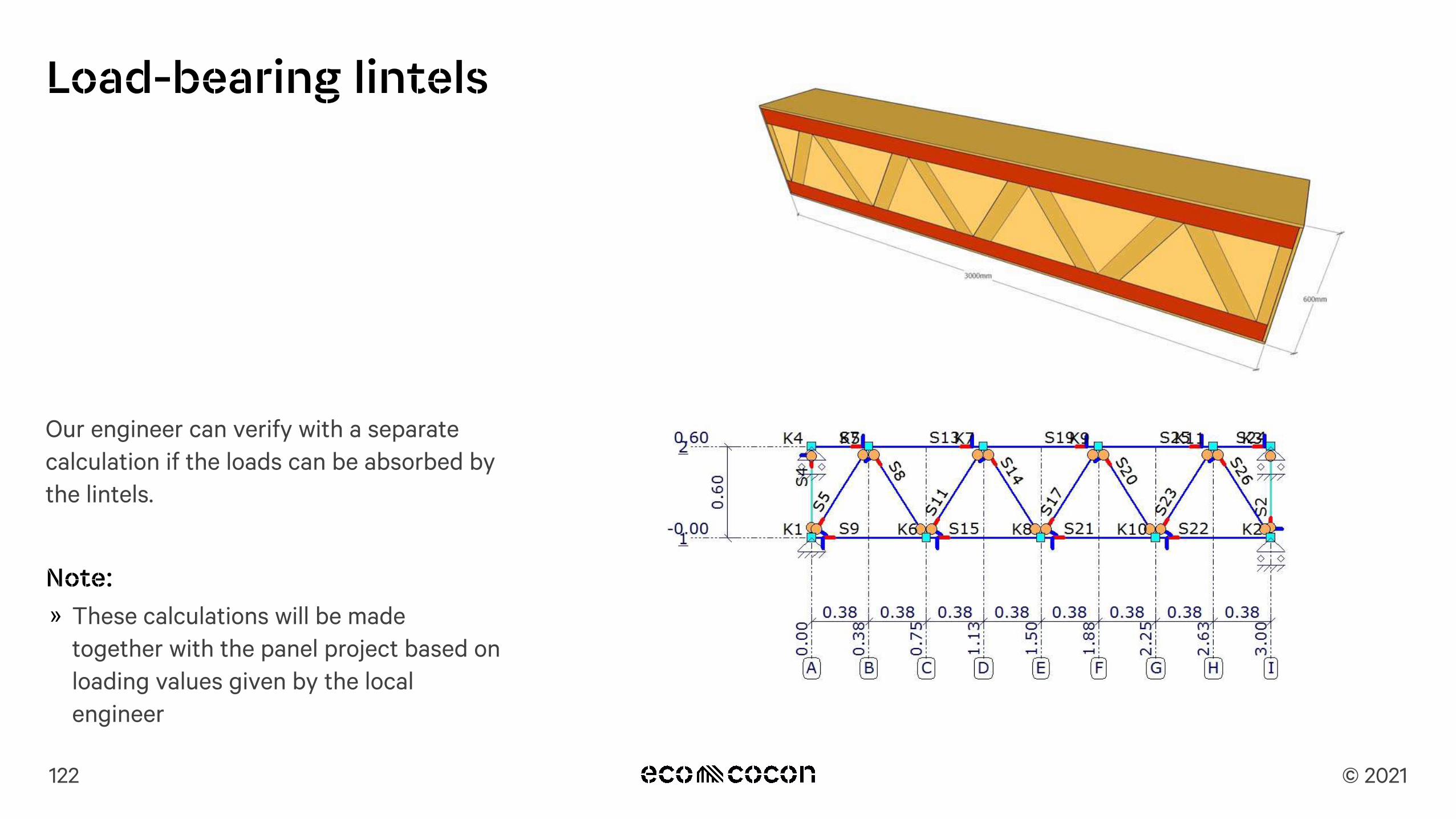
Load-bearing lintels
Our engineer can verify with a separate calculation if the loads can be absorbed by the lintels.
Note: » These calculations will be made
together with the panel project based on loading values given by the local engineer
122
Permanent action:
≔gk1 2.4 kPa
≔gd1 =⋅gk1 γG 3.24 kPa
Variable action:
≔qks =⋅⋅⋅⋅0.8 1.0 1.0 1.6 kPa 1.28 kPa ≔qkw ⋅0.89 kPa
≔qk1 =+qks qkw 2.17 kPa
≔qd1 =⋅qk1 γQ 2.821 kPa
Sum of roof actions: ≔P1 =+gd1 qd1 6.061 kPa
Loading on the wall: ≔p =⋅⋅P1 B 0.5 18.183 ――kNm
Calculation is made according to !nite element program "MatrixFrame":
Max forces in the lintel web:
Max Axial compressive force in S19: ≔NC.max.d 33.20 kN
Max Axial tension force in S15 and S21: ≔NT.max.d 33.21 kN
Max Shear force in S13 and S25: ≔Vmax.d 7.10 kN
Max Bending force in S19: ≔Mmax.d ⋅0.77 kN m
Panel in whole construction and weakest part of panel
Fig 2. Side section of panel
Fig 1. Total view
Fig 3. 3D view of panel
Lintel members designGeometric parameters:
Height: ≔h ⋅95 mm Width: ≔b ⋅45 mm
Section area: ≔A =⋅h b 0.004 m2 Span: ≔B 6.0 m
Section modulus about the strong axis:Moment of inertia: ≔I =――⋅b h3
12321.516 cm4 ≔W =――⋅b h2
667.688 cm3
Factor for constant load: ≔γG 1.35 Factor for variable load: ≔γQ 1.30
P i

© 2021
Sample calculation
123
Panel type Weakest pointMax linear load
kN/m Breaking factor
Panel Post 19.04 Axial forceColumn Post 22.24 Axial force
Lintel 60 cm height Bottom flange 29.55 Bending moment
Panel (view from top)
Column (View from top)
Lintel (side view)
Loads valid for inner or outer
side of the panel.

© 2021
Sample calculation
124
23,048kN / 0,6875m = 33,524kN/m
36,184kN /1,9m = 19,044kN/m
3m - max. 29,55 kN/m Bottom Flange
38,925 / 1,75 = 22,243 kN/m
29,55 / 1 = 29,55kN/m
Lowest Value 19,044 kN/m is max. load!
35,700kN / 0,25m = 142,800kN/m 11,524kN / 0,2875m = 40,084kN/m

© 2021
Panel supporting another panel
» Posts should be in one line if 2nd floor panels are supported directly on 1st floor panels.
125
or