Embed Size (px)
DESCRIPTION
Hull Structural Design -Basic Design
Citation preview

Hull Structural Design
User Guide

AVEVA Solutions Limited
Disclaimer1.1 AVEVA does not warrant that the use of the AVEVA software will be uninterrupted, error-free or free fromviruses.
1.2 AVEVA shall not be liable for: loss of profits; loss of business; depletion of goodwill and/or similar losses; loss ofanticipated savings; loss of goods; loss of contract; loss of use; loss or corruption of data or information; anyspecial, indirect, consequential or pure economic loss, costs, damages, charges or expenses which may besuffered by the user, including any loss suffered by the user resulting from the inaccuracy or invalidity of any datacreated by the AVEVA software, irrespective of whether such losses are suffered directly or indirectly, or arise incontract, tort (including negligence) or otherwise.
1.3 AVEVA's total liability in contract, tort (including negligence), or otherwise, arising in connection with theperformance of the AVEVA software shall be limited to 100% of the licence fees paid in the year in which the user'sclaim is brought.
1.4 Clauses 1.1 to 1.3 shall apply to the fullest extent permissible at law.
1.5 In the event of any conflict between the above clauses and the analogous clauses in the software licence underwhich the AVEVA software was purchased, the clauses in the software licence shall take precedence.
CopyrightCopyright and all other intellectual property rights in this manual and the associated software, and every part of it(including source code, object code, any data contained in it, the manual and any other documentation suppliedwith it) belongs to, or is validly licensed by, AVEVA Solutions Limited or its subsidiaries.
All rights are reserved to AVEVA Solutions Limited and its subsidiaries. The information contained in this documentis commercially sensitive, and shall not be copied, reproduced, stored in a retrieval system, or transmitted withoutthe prior written permission of AVEVA Solutions Limited. Where such permission is granted, it expressly requiresthat this copyright notice, and the above disclaimer, is prominently displayed at the beginning of every copy that ismade.
The manual and associated documentation may not be adapted, reproduced, or copied, in any material orelectronic form, without the prior written permission of AVEVA Solutions Limited. The user may not reverseengineer, decompile, copy, or adapt the software. Neither the whole, nor part of the software described in thispublication may be incorporated into any third-party software, product, machine, or system without the prior writtenpermission of AVEVA Solutions Limited, save as permitted by law. Any such unauthorised action is strictlyprohibited, and may give rise to civil liabilities and criminal prosecution.
The AVEVA software described in this guide is to be installed and operated strictly in accordance with the termsand conditions of the respective software licences, and in accordance with the relevant User Documentation.Unauthorised or unlicensed use of the software is strictly prohibited.
Copyright 1974 to current year. AVEVA Solutions Limited and its subsidiaries. All rights reserved. AVEVA shall notbe liable for any breach or infringement of a third party's intellectual property rights where such breach results froma user's modification of the AVEVA software or associated documentation.
AVEVA Solutions Limited, High Cross, Madingley Road, Cambridge, CB3 0HB, United Kingdom.
TrademarkAVEVA and Tribon are registered trademarks of AVEVA Solutions Limited or its subsidiaries. Unauthorised use ofthe AVEVA or Tribon trademarks is strictly forbidden.
AVEVA product/software names are trademarks or registered trademarks of AVEVA Solutions Limited or itssubsidiaries, registered in the UK, Europe and other countries (worldwide).
The copyright, trademark rights, or other intellectual property rights in any other product or software, its name orlogo belongs to its respective owner.

Hull Structural Design User Guide
Revision Sheet
Date Version Comments / Remarks
September 2011 12.1.1 Functions Overview, RSO updates, Functions in the XML menu,2D Import and Shell Curve - From External Surface.
Added to the Surfaces dialog in Structural design about how todelete a surface.
January 2012 Copyright added to all pages.
October 2012 12.1.SP3 Removed Tribon, changed Job Launcher to Log Viewer.
October 2012 12.1.SP3 Extensive updates to chapter 6 Finite Element Model.
October 2012 12.1.SP3 Updates to chapter Utilities, Extracting RSO Information.
April 2013 12.1.SP4 Update about Stiffeners in chapter Finite Element Model.
April 2013 12.1.SP4 Updated 5 Block Division.
April 2013 12.1.SP4 New chapter - 9 Default File of Structural Design

Hull Structural Design User Guide

Hull Structural Design User Guide
Contents Page
Hull Structural Design User GuideContents
Hull Structural DesignIntroduction to the Usage of Structural Design . . . . . . . . . . . . . . . . 1:1Fast Modelling . . . . . . . . . . . . . . . . . . . . . . . . . . . . . . . . . . . . . . . . . . . . . . . . . . . . 1:1Functional Structures . . . . . . . . . . . . . . . . . . . . . . . . . . . . . . . . . . . . . . . . . . . . . . . . . . . . . . 1:2Quick Panels . . . . . . . . . . . . . . . . . . . . . . . . . . . . . . . . . . . . . . . . . . . . . . . . . . . . . . . . . . . . 1:2
Early Analysis and Estimates . . . . . . . . . . . . . . . . . . . . . . . . . . . . . . . . . . . . . . . . 1:2Reports for Estimates. . . . . . . . . . . . . . . . . . . . . . . . . . . . . . . . . . . . . . . . . . . . . . . . . . . . . . 1:2
Generation of Drawings. . . . . . . . . . . . . . . . . . . . . . . . . . . . . . . . . . . . . . . . . . . . . 1:2Smooth Transition to Detail Design . . . . . . . . . . . . . . . . . . . . . . . . . . . . . . . . . . . 1:3Functional Panels. . . . . . . . . . . . . . . . . . . . . . . . . . . . . . . . . . . . . . . . . . . . . . . . . . . . . . . . . 1:3Division of Steel into Main Building Blocks. . . . . . . . . . . . . . . . . . . . . . . . . . . . . . . . . . . . . . 1:3
Some Design Scenarios . . . . . . . . . . . . . . . . . . . . . . . . . . . . . . . . . . . 2:1Scenario 1 - Start from Scratch . . . . . . . . . . . . . . . . . . . . . . . . . . . . . . . . . . . . . . 2:1Scenario 2 - Design Based on Existing Initial Project Data . . . . . . . . . . . . . . . . 2:1Common to both Scenarios . . . . . . . . . . . . . . . . . . . . . . . . . . . . . . . . . . . . . . . . . 2:2
Project Set-up . . . . . . . . . . . . . . . . . . . . . . . . . . . . . . . . . . . . . . . . . . . 3:1Using the Template Project . . . . . . . . . . . . . . . . . . . . . . . . . . . . . . . . . . . . . . . . . . 3:1Surface . . . . . . . . . . . . . . . . . . . . . . . . . . . . . . . . . . . . . . . . . . . . . . . . . . . . . . . . 3:1Standards . . . . . . . . . . . . . . . . . . . . . . . . . . . . . . . . . . . . . . . . . . . . . . . . . . . . . . . . 3:1
Multi-View Project . . . . . . . . . . . . . . . . . . . . . . . . . . . . . . . . . . . . . . . . 4:1Design View - Production View. . . . . . . . . . . . . . . . . . . . . . . . . . . . . . . . . . . . . . . 4:1
12 Seriesi© Copyright 1974 to current year.AVEVA Solutions Limited and its subsidiaries. All rights reserved.

Hull Structural Design User GuideContents
Design Panels - Production Panels . . . . . . . . . . . . . . . . . . . . . . . . . . . . . . . . . . . . . . . . . . . 4:1Design Blocks - Production Blocks. . . . . . . . . . . . . . . . . . . . . . . . . . . . . . . . . . . . . . . . . . . . 4:2
Creating a Multi-View Project . . . . . . . . . . . . . . . . . . . . . . . . . . . . . . . . . . . . . . . . 4:2Starting a New Project . . . . . . . . . . . . . . . . . . . . . . . . . . . . . . . . . . . . . . . . . . . . . . . . . . . . . 4:2Converting an Existing Project . . . . . . . . . . . . . . . . . . . . . . . . . . . . . . . . . . . . . . . . . . . . . . . 4:3
Design - Production Connections . . . . . . . . . . . . . . . . . . . . . . . . . . . . . . . . . . . . 4:3Block Seams . . . . . . . . . . . . . . . . . . . . . . . . . . . . . . . . . . . . . . . . . . . . . . . . . . . . . . . . . . . . 4:4Panel Boundary . . . . . . . . . . . . . . . . . . . . . . . . . . . . . . . . . . . . . . . . . . . . . . . . . . . . . . . . . . 4:4
Production Data . . . . . . . . . . . . . . . . . . . . . . . . . . . . . . . . . . . . . . . . . . . . . . . . . . . 4:4
Block Division . . . . . . . . . . . . . . . . . . . . . . . . . . . . . . . . . . . . . . . . . . . 5:1Purpose . . . . . . . . . . . . . . . . . . . . . . . . . . . . . . . . . . . . . . . . . . . . . . . . . . . . . . . . 5:1Panel Selection. . . . . . . . . . . . . . . . . . . . . . . . . . . . . . . . . . . . . . . . . . . . . . . . . . . . 5:2Cutting . . . . . . . . . . . . . . . . . . . . . . . . . . . . . . . . . . . . . . . . . . . . . . . . . . . . . . . . 5:2Sorting . . . . . . . . . . . . . . . . . . . . . . . . . . . . . . . . . . . . . . . . . . . . . . . . . . . . . . . . 5:2Target Blocks and Cutters . . . . . . . . . . . . . . . . . . . . . . . . . . . . . . . . . . . . . . . . . . 5:2Boundary Creation. . . . . . . . . . . . . . . . . . . . . . . . . . . . . . . . . . . . . . . . . . . . . . . . . 5:4Large Openings . . . . . . . . . . . . . . . . . . . . . . . . . . . . . . . . . . . . . . . . . . . . . . . . . . . . . . . . . . 5:4U-shaped Panels . . . . . . . . . . . . . . . . . . . . . . . . . . . . . . . . . . . . . . . . . . . . . . . . . . . . . . . . . 5:4
Components . . . . . . . . . . . . . . . . . . . . . . . . . . . . . . . . . . . . . . . . . . . . . . . . . . . . . . 5:4Block Seam Properties . . . . . . . . . . . . . . . . . . . . . . . . . . . . . . . . . . . . . . . . . . . . . 5:5Verification of the Result . . . . . . . . . . . . . . . . . . . . . . . . . . . . . . . . . . . . . . . . . . . . 5:5Iterative Block Division . . . . . . . . . . . . . . . . . . . . . . . . . . . . . . . . . . . . . . . . . . . . . 5:5The Interactive Interface . . . . . . . . . . . . . . . . . . . . . . . . . . . . . . . . . . . . . . . . . . . . 5:6The Job . . . . . . . . . . . . . . . . . . . . . . . . . . . . . . . . . . . . . . . . . . . . . . . . . . . . . . . . . . . . . . 5:7Selected Objects . . . . . . . . . . . . . . . . . . . . . . . . . . . . . . . . . . . . . . . . . . . . . . . . . . . . . . . . . 5:8Cutters . . . . . . . . . . . . . . . . . . . . . . . . . . . . . . . . . . . . . . . . . . . . . . . . . . . . . . . . . . . . . . 5:9Target Blocks . . . . . . . . . . . . . . . . . . . . . . . . . . . . . . . . . . . . . . . . . . . . . . . . . . . . . . . . . . . 5:12Logs . . . . . . . . . . . . . . . . . . . . . . . . . . . . . . . . . . . . . . . . . . . . . . . . . . . . . . . . . . . . . 5:13Limitations . . . . . . . . . . . . . . . . . . . . . . . . . . . . . . . . . . . . . . . . . . . . . . . . . . . . . . . . . . . . . 5:13
Block Division as a Background Process . . . . . . . . . . . . . . . . . . . . . . . . . . . . . 5:13
Finite Element Model . . . . . . . . . . . . . . . . . . . . . . . . . . . . . . . . . . . . . 6:1Idealized Model. . . . . . . . . . . . . . . . . . . . . . . . . . . . . . . . . . . . . . . . . . . . . . . . . . . . 6:2Prerequisities . . . . . . . . . . . . . . . . . . . . . . . . . . . . . . . . . . . . . . . . . . . . . . . . . . . . . . . . . . . . 6:4Model Selection . . . . . . . . . . . . . . . . . . . . . . . . . . . . . . . . . . . . . . . . . . . . . . . . . . . . . . . . . . 6:5Idealisation Settings . . . . . . . . . . . . . . . . . . . . . . . . . . . . . . . . . . . . . . . . . . . . . . . . . . . . . . . 6:6
12 Seriesii© Copyright 1974 to current year.AVEVA Solutions Limited and its subsidiaries. All rights reserved.
Hull Structural Design User GuideContents
Running the Idealisation. . . . . . . . . . . . . . . . . . . . . . . . . . . . . . . . . . . . . . . . . . . . . . . . . . . 6:18
FE Model Creation . . . . . . . . . . . . . . . . . . . . . . . . . . . . . . . . . . . . . . . . . . . . . . . . 6:20FE Model Options. . . . . . . . . . . . . . . . . . . . . . . . . . . . . . . . . . . . . . . . . . . . . . . . . . . . . . . . 6:21Running the FE Modelling Process . . . . . . . . . . . . . . . . . . . . . . . . . . . . . . . . . . . . . . . . . . 6:30
FE Model Output . . . . . . . . . . . . . . . . . . . . . . . . . . . . . . . . . . . . . . . . . . . . . . . . . 6:32Export FE Model to ANSYS APDL. . . . . . . . . . . . . . . . . . . . . . . . . . . . . . . . . . . . . . . . . . . 6:33Export FE Model to Patran PCL. . . . . . . . . . . . . . . . . . . . . . . . . . . . . . . . . . . . . . . . . . . . . 6:34FE Model Included in the Hull Steel XML Export . . . . . . . . . . . . . . . . . . . . . . . . . . . . . . . . 6:34Material Qualities . . . . . . . . . . . . . . . . . . . . . . . . . . . . . . . . . . . . . . . . . . . . . . . . . . . . . . . . 6:34
Remarks on this Documentation . . . . . . . . . . . . . . . . . . . . . . . . . . . . 7:1
Functions Overview . . . . . . . . . . . . . . . . . . . . . . . . . . . . . . . . . . . . . . 8:1Functions in the Project Menu . . . . . . . . . . . . . . . . . . . . . . . . . . . . . . . . . . . . . . . 8:1Surfaces . . . . . . . . . . . . . . . . . . . . . . . . . . . . . . . . . . . . . . . . . . . . . . . . . . . . . . . . . . . . . . 8:1FR/LP Positions . . . . . . . . . . . . . . . . . . . . . . . . . . . . . . . . . . . . . . . . . . . . . . . . . . . . . . . . . . 8:2Block . . . . . . . . . . . . . . . . . . . . . . . . . . . . . . . . . . . . . . . . . . . . . . . . . . . . . . . . . . . . . . 8:3Midbody Surface . . . . . . . . . . . . . . . . . . . . . . . . . . . . . . . . . . . . . . . . . . . . . . . . . . . . . . . . . 8:6Envelope . . . . . . . . . . . . . . . . . . . . . . . . . . . . . . . . . . . . . . . . . . . . . . . . . . . . . . . . . . . . . . 8:7Verify Model . . . . . . . . . . . . . . . . . . . . . . . . . . . . . . . . . . . . . . . . . . . . . . . . . . . . . . . . . . . . . 8:7Recreate Limit Tables . . . . . . . . . . . . . . . . . . . . . . . . . . . . . . . . . . . . . . . . . . . . . . . . . . . . . 8:9Project Information . . . . . . . . . . . . . . . . . . . . . . . . . . . . . . . . . . . . . . . . . . . . . . . . . . . . . . . . 8:9Change View Mode . . . . . . . . . . . . . . . . . . . . . . . . . . . . . . . . . . . . . . . . . . . . . . . . . . . . . . 8:10
Functions in the Functional Structure Menu. . . . . . . . . . . . . . . . . . . . . . . . . . . 8:10RSO . . . . . . . . . . . . . . . . . . . . . . . . . . . . . . . . . . . . . . . . . . . . . . . . . . . . . . . . . . . . . 8:10Merge Panels . . . . . . . . . . . . . . . . . . . . . . . . . . . . . . . . . . . . . . . . . . . . . . . . . . . . . . . . . . . 8:25Pending updates . . . . . . . . . . . . . . . . . . . . . . . . . . . . . . . . . . . . . . . . . . . . . . . . . . . . . . . . 8:26Divide into Blocks . . . . . . . . . . . . . . . . . . . . . . . . . . . . . . . . . . . . . . . . . . . . . . . . . . . . . . . . 8:26
Functions in the Planar Menu . . . . . . . . . . . . . . . . . . . . . . . . . . . . . . . . . . . . . . . 8:26Model . . . . . . . . . . . . . . . . . . . . . . . . . . . . . . . . . . . . . . . . . . . . . . . . . . . . . . . . . . . . . 8:27Panel . . . . . . . . . . . . . . . . . . . . . . . . . . . . . . . . . . . . . . . . . . . . . . . . . . . . . . . . . . . . . 8:31Scheme . . . . . . . . . . . . . . . . . . . . . . . . . . . . . . . . . . . . . . . . . . . . . . . . . . . . . . . . . . . . . 8:37Editor . . . . . . . . . . . . . . . . . . . . . . . . . . . . . . . . . . . . . . . . . . . . . . . . . . . . . . . . . . . . . 8:41View . . . . . . . . . . . . . . . . . . . . . . . . . . . . . . . . . . . . . . . . . . . . . . . . . . . . . . . . . . . . . 8:42PosNo . . . . . . . . . . . . . . . . . . . . . . . . . . . . . . . . . . . . . . . . . . . . . . . . . . . . . . . . . . . . . 8:48Select . . . . . . . . . . . . . . . . . . . . . . . . . . . . . . . . . . . . . . . . . . . . . . . . . . . . . . . . . . . . . 8:48
Functions in the Curved Menu . . . . . . . . . . . . . . . . . . . . . . . . . . . . . . . . . . . . . . 8:50Model . . . . . . . . . . . . . . . . . . . . . . . . . . . . . . . . . . . . . . . . . . . . . . . . . . . . . . . . . . . . . 8:51The Geometry Menu . . . . . . . . . . . . . . . . . . . . . . . . . . . . . . . . . . . . . . . . . . . . . . . . . . . . . 8:63
12 Seriesiii© Copyright 1974 to current year.AVEVA Solutions Limited and its subsidiaries. All rights reserved.

Hull Structural Design User GuideContents
The Default Menu. . . . . . . . . . . . . . . . . . . . . . . . . . . . . . . . . . . . . . . . . . . . . . . . . . . . . . . . 8:72The View Menu . . . . . . . . . . . . . . . . . . . . . . . . . . . . . . . . . . . . . . . . . . . . . . . . . . . . . . . . . 8:73The Select Menu . . . . . . . . . . . . . . . . . . . . . . . . . . . . . . . . . . . . . . . . . . . . . . . . . . . . . . . . 8:77
Functions in the XML Menu . . . . . . . . . . . . . . . . . . . . . . . . . . . . . . . . . . . . . . . . 8:81Import . . . . . . . . . . . . . . . . . . . . . . . . . . . . . . . . . . . . . . . . . . . . . . . . . . . . . . . . . . . . . 8:81Export . . . . . . . . . . . . . . . . . . . . . . . . . . . . . . . . . . . . . . . . . . . . . . . . . . . . . . . . . . . . . 8:85
Functions in the Analysis Menu . . . . . . . . . . . . . . . . . . . . . . . . . . . . . . . . . . . . . 8:87Section Modulus. . . . . . . . . . . . . . . . . . . . . . . . . . . . . . . . . . . . . . . . . . . . . . . . . . . . . . . . . 8:87Weld Calculation . . . . . . . . . . . . . . . . . . . . . . . . . . . . . . . . . . . . . . . . . . . . . . . . . . . . . . . . 8:88Block Preliminary WCOG. . . . . . . . . . . . . . . . . . . . . . . . . . . . . . . . . . . . . . . . . . . . . . . . . . 8:89WCOG . . . . . . . . . . . . . . . . . . . . . . . . . . . . . . . . . . . . . . . . . . . . . . . . . . . . . . . . . . . . . 8:90Material List . . . . . . . . . . . . . . . . . . . . . . . . . . . . . . . . . . . . . . . . . . . . . . . . . . . . . . . . . . . . 8:90Painting Areas . . . . . . . . . . . . . . . . . . . . . . . . . . . . . . . . . . . . . . . . . . . . . . . . . . . . . . . . . . 8:91Idealize Model . . . . . . . . . . . . . . . . . . . . . . . . . . . . . . . . . . . . . . . . . . . . . . . . . . . . . . . . . . 8:91Create FE Model . . . . . . . . . . . . . . . . . . . . . . . . . . . . . . . . . . . . . . . . . . . . . . . . . . . . . . . . 8:92Export FE Model to ANSYS APDL. . . . . . . . . . . . . . . . . . . . . . . . . . . . . . . . . . . . . . . . . . . 8:93Export FE Model to Patran PCL. . . . . . . . . . . . . . . . . . . . . . . . . . . . . . . . . . . . . . . . . . . . . 8:93
Right Click Context Menus . . . . . . . . . . . . . . . . . . . . . . . . . . . . . . . . . . . . . . . . . 8:93
Default File of Structural Design . . . . . . . . . . . . . . . . . . . . . . . . . . . . 9:1
Batch Utilities . . . . . . . . . . . . . . . . . . . . . . . . . . . . . . . . . . . . . . . . . . 10:1Block Division . . . . . . . . . . . . . . . . . . . . . . . . . . . . . . . . . . . . . . . . . . . . . . . . . . . 10:1General . . . . . . . . . . . . . . . . . . . . . . . . . . . . . . . . . . . . . . . . . . . . . . . . . . . . . . . . . . . . . 10:1Set-up of Program . . . . . . . . . . . . . . . . . . . . . . . . . . . . . . . . . . . . . . . . . . . . . . . . . . . . . . . 10:1Input . . . . . . . . . . . . . . . . . . . . . . . . . . . . . . . . . . . . . . . . . . . . . . . . . . . . . . . . . . . . . 10:1Output Files . . . . . . . . . . . . . . . . . . . . . . . . . . . . . . . . . . . . . . . . . . . . . . . . . . . . . . . . . . . . 10:3
Extracting RSO Information . . . . . . . . . . . . . . . . . . . . . . . . . . . . . . . . . . . . . . . . 10:3Updating RSO Information . . . . . . . . . . . . . . . . . . . . . . . . . . . . . . . . . . . . . . . . . 10:6Generate Steel from RSO . . . . . . . . . . . . . . . . . . . . . . . . . . . . . . . . . . . . . . . . . . 10:6Create/Remove Design Blocks and Panels . . . . . . . . . . . . . . . . . . . . . . . . . . . . 10:7
12 Seriesiv© Copyright 1974 to current year.AVEVA Solutions Limited and its subsidiaries. All rights reserved.

Hull Structural Design User GuideIntroduction to the Usage of Structural Design
1 Introduction to the Usage of Structural Design
The basic elements of a ship design depend on each other and these dependencies areregistered in AVEVA Marine. Any change to the design will affect a number of elementsthroughout the ship. When refining the design, these registered relationships betweenelements can be made use of.
AVEVA Marine Structural Design supports the designer in decisions regarding thepreliminary definition and arrangement of some of these elements, namely the main shipstructures and major equipment. It also provides the framework for associated designguidance. The design can be refined to a level, where classification drawings, preliminarysteel material estimates, weld lengths and weights and centres of gravity reports can beproduced.
Initial and preliminary design is less resource demanding than detail design, but the amountof work needed for detail design is strongly dependent on the level of the preliminary design.This is illustrated by the fact that a very large percentage of the building cost is allocatedduring the first steps in the design process. All preliminary structural definitions developedby Structural Design can be used directly by other AVEVA Marine applications for detaildesign and preparation of production information (Hull, Outfit, Assembly Planning etc.). Thisensures that no definition or arrangement made during the preliminary design has to bedone all over again in the detail design phase. Another benefit of speeding up the initial andpreliminary design phase by using AVEVA Marine Structural Design is that a larger numberof design alternatives can be compared and that approval from the relevant classificationsociety can be obtained much earlier. This will lead to a better design, from both a technicaland economical point of view. With this background, Structural Design is the focus of on fourmajor areas:
1. Fast Modelling2. Early Analysis and Estimates3. Generation of Drawings4. Smooth Transition to Detail Design
1.1 Fast ModellingThe intention of the Structural Design is to support automatic or semi-automatic modelling ofthe main structures (the Functional Panels) of a design, independently of the designscenario. To support this, two major sets of tools are available:
• The definition of Functional Structures from the Reference Surface Objects (RSO)allowing for automatically generated Functional Panels.
• The usage of the AVEVA Marine Vitesse technology for the definition of Quick Panels.
12 Series 1:1© Copyright 1974 to current year.AVEVA Solutions Limited and its subsidiaries. All rights reserved.

Hull Structural Design User GuideIntroduction to the Usage of Structural Design
1.1.1 Functional StructuresWhen defining the compartmentation in AVEVA Marine Surface/Compartments, the mainRSOs are defined as the compartment limits. These RSOs are forming the basis for theFunctional Structures. Furthermore, a tool in Structural Design is provided to allow the userto also define additional RSOs in principle planes.
Having the RSOs, tools are provided that allows definition of properties (e.g. materials, endconnections, etc.) of individual RSOs. The definition is turning the RSOs into FunctionalStructures, which are used for the automatic generation of Functional Panels in the innerstructure of the ship.
1.1.2 Quick PanelsA Quick Panel is a customised Vitesse script, designed to generate a specific type of hullstructure.
A number of Quick Panel functions for some major inner structure types are provided withthe Structural Design system. The functions are defined using the Vitesse technology, whichallows for customization to shipyard practice or different ship types. The intention of thesupplied scripts is to serve as examples for customer adaptations.
1.2 Early Analysis and EstimatesAnalysis and estimate tools are either internally provided within Structural Design (e.g.Section Modulus) or externally provided via a XML interface to functionality in externalsoftware (e.g. Class Societies).
The tools can be used as soon as Functional Panels are available.
1.2.1 Reports for EstimatesCurrently, the following types of reports can be extracted using Structural Design:
• Weights and Centres of Gravity• Steel Material Contents• Weld Length Estimates• Painting Area Calculations
1.3 Generation of DrawingsThe modelling tools within AVEVA Marine are completely integrated with the Drafting toolsto generate design drawings. Modelling can actually be performed using any of the drawingviews generated from the model, e.g. a symbolic hull view, a shell expansion view, a 3Dview, etc. The model drawings are generated simultaneously, without additional procedures.
The functions to create different types of drawing views can be found in the View menus forplanar and curved hull and can be used to produce typical drawings:
• General Arrangement• Body Plan• Shell Expansion• Midship Section• Elevations and Profiles
12 Series 1:2© Copyright 1974 to current year.AVEVA Solutions Limited and its subsidiaries. All rights reserved.

Hull Structural Design User GuideIntroduction to the Usage of Structural Design
• Typical Sections
1.4 Smooth Transition to Detail Design
1.4.1 Functional PanelsThe full implementation of the Functional Panel concept will support two alternative views ofa design at the same time, either a structural design view or a detailed design view.However, this is subject for a later version. In the current version of AVEVA Marine, theFunctional Panel can be considered as any normal panel.
1.4.2 Division of Steel into Main Building BlocksThe basic design model shall be used as basis for the detail design. At some point in time,the production block break-down structure will be defined and used to create the individualProduction Panels.
12 Series 1:3© Copyright 1974 to current year.AVEVA Solutions Limited and its subsidiaries. All rights reserved.

Hull Structural Design User GuideIntroduction to the Usage of Structural Design
12 Series 1:4© Copyright 1974 to current year.AVEVA Solutions Limited and its subsidiaries. All rights reserved.

Hull Structural Design User GuideSome Design Scenarios
2 Some Design Scenarios
2.1 Scenario 1 - Start from ScratchIn this scenario a typical merchant vessel configuration is assumed. The final surface is notyet available, so a rough surface describing only the parallel mid-body is created initiallytogether with the main Reference Surface Objects (RSO).
First the main longitudinal members are created, such as:• Shell plating • Shell longitudinals• Decks• Longitudinal bulkheads• Girders• Stringers
Shell plating and longitudinals are generated using the interactive functions for this purpose.The inner structures can be made up to a certain detail level using automatic generation ofpanels on RSOs or using the Quick Panel functions. Further detailing and modifications arethen made using the interactive functions for this purpose.
In this stage a check can be made to see if the required sectional modulus is achieved. Ifnot, an iterative process is started in which the designer makes changes to the longitudinalmaterial to obtain the desired sectional modulus.
When this is achieved, the transverse members are modelled, such as:• Transverse bulkheads• Webs• Floors
At this stage, the design can be refined even further by going through the above procedureagain. When the design fulfils all demands a first approval of the midship cross-section fromthe relevant classification society can be obtained.
Then a preliminary or final surface for the whole ship can be imported, and extension ofstructure is made into the fore and aft bodies of the ship.
2.2 Scenario 2 - Design Based on Existing Initial Project DataIn this scenario a cruise liner configuration is assumed, where the hull surface andcompartmentation is set.
12 Series 2:1© Copyright 1974 to current year.AVEVA Solutions Limited and its subsidiaries. All rights reserved.

Hull Structural Design User GuideSome Design Scenarios
The main steel structures (decks, bulkheads, etc.) are created using the RSOs from thesurface/ compartment definitions.
Then the stiffeners and longitudinals are defined and a check is made against the requiredsectional modulus. All longitudinal material is created along the entire length of the ship.
Typical transverse bulkhead arrangements, webs and floors are modelled.
2.3 Common to both ScenariosThe two scenarios above continue with the following common activities:
• Definition and placing of main equipment.• Estimates• Drawing Generation
Division of steel structure into main building blocks.
12 Series 2:2© Copyright 1974 to current year.AVEVA Solutions Limited and its subsidiaries. All rights reserved.

Hull Structural Design User GuideProject Set-up
3 Project Set-up
3.1 Using the Template ProjectA template project with default settings and standards is available together with a AVEVAMarine installation. The template project is located under the AVEVA Marine root directory.Further instructions how to use the template and to set-up a new project can be found inAdministration of AVEVA Marine Environment.
Customers should generate their own template projects for different types of ships, makingthe project set-up
3.2 SurfaceTo get general access to the released surfaces in terms of intersection data as well ascontained curve definition data a Hull Reference Object must be created in the project. Thisobject defines which surfaces should be accessed as well as the corresponding type ofthese surfaces.
Further details on the project setup and the creation of the Hull Reference Object can befound in User Guide Hull / Setup and Customisation / General / Surface Setup.
Once the Hull Reference Object is created, additional surfaces can be registered using thefunction Project / Surfaces in Structural Design.
3.3 StandardsThe project set-up also includes customising of standards, both yard and project specificones. Typically, the template projects contain the yard specific standards for specific shiptypes, while the project set-up must be made on each created project.
A survey of the standards in can be found in Hull Model Concepts / Standards with furtherlinks to the actual set-up procedures to be performed.
12 Series 3:1© Copyright 1974 to current year.AVEVA Solutions Limited and its subsidiaries. All rights reserved.

Hull Structural Design User GuideProject Set-up
12 Series 3:2© Copyright 1974 to current year.AVEVA Solutions Limited and its subsidiaries. All rights reserved.

Hull Structural Design User GuideMulti-View Project
4 Multi-View Project
In the early stages of the hull design process the focus is on defining the model to the extentthat satisfies the functional requirements such as strength. It should also be possible toperform basic calculations such as steel weights and weld lengths with an acceptableaccuracy. In the later stages of refining the model the focus turns into providing allnecessary information to enable the manufacturing of parts and collection of assemblies.The demands on the hull model, or rather the view of the hull model, is thus somewhatdifferent between the early and late stages of modelling.
In order to support these different model views the concept of Multi-View projects has beendeveloped. The Design View supports the early stages showing large panels withoutproduction details organized in a few blocks while the Production View panels have fullproduction details organized in blocks adapted to the manufacturing demands. HullStructural Design has the option to create and handle Multi-View projects. However it is anoption, the ordinary single view environment is available if wanted.
The Design and Production views are to be seen as two views of the same Hull ProductModel. Thus the two views exist at the same time and the user has a choice which one ofthe views to use as the gateway to the Product Model. This means that in a fully populatedmodel a block or a panel in the Design view have its corresponding blocks or panels in theProduction view. Unless otherwise stated panel means plane panel in this chapter.
4.1 Design View - Production ViewA Multi-View project can be viewed either via the Design View or the Production View. Amodal switch is used to shift between the views. In the Design View only the Design Blocksand the Design Panels are shown and in the Production View then only Production Blocksand Panels are shown. This goes for all functions involving graphical viewing and block/panel listings.
Hull Detail Design will always use and see the Production View of a Multi-View project, whileOutfitting can select freely which view to be displayed and referenced to.
4.1.1 Design Panels - Production PanelsIn a Multi-View project any Production Panel has a corresponding Design Panel. A DesignPanel may have corresponding Production Panels if the project has reached that stage. TheDesign and Production Panels are really separate objects, but the system automaticallymaintains the connections between corresponding panels.
A Production Panel is connected to a single Design Panel while a Design Panel can berepresented by multiple Production Panels.
A modification in a Design Panel is reflected in its Production Panels and vice versa. This isdone automatically by the system but under user control. If e.g. a Design Panel is modified
12 Series 4:1© Copyright 1974 to current year.AVEVA Solutions Limited and its subsidiaries. All rights reserved.

Hull Structural Design User GuideMulti-View Project
and committed, the user will be prompted to accept the update of a connected ProductionPanel when it is activated.
4.1.2 Design Blocks - Production BlocksAs for the panels the blocks are of two kinds in a Multi-View Project, Design Blocks andProduction Blocks. As for the panels a Production block is connected to a single DesignBlock that must enclose it, while a Design Block may refer several Production Blocks.
4.2 Creating a Multi-View ProjectA Multi-View Project is a project containing at least one Design Block. If blocks exist that arenot Design Blocks it is an ordinary project.
4.2.1 Starting a New ProjectStarting with an empty project the project type is determined by the first block created. If aDesign Block is created the project will become a Multi-View project and if a ProductionBlock (ordinary block) is created it will become an ordinary project.
12 Series 4:2© Copyright 1974 to current year.AVEVA Solutions Limited and its subsidiaries. All rights reserved.

Hull Structural Design User GuideMulti-View Project
Initially the new Multi-View project will only contain Design Blocks and Design Panels. Oncethe project model at least in some area is ready to be promoted to the production phase theProduction Blocks can be created and the Production Panels created by use of the BlockDivide function (see chapter Block Division).
A Design Block/Panel can only be created in a Multi-View project and not in an ordinaryproject. In a Multi-View Project any Production Block/Panel must be connected to a DesignBlock/Panel.
If a Production Panel is created in a Multi-View Project it will get a Design Panel counterpartautomatically created as a copy of the Production Panel in the connected Design Block.
4.2.2 Converting an Existing ProjectBy a special utility it is possible to make a Multi-View project out of an ordinary project or toconvert a Multi-View project back to a Single-View. Further information can be found inCreate/Remove Design Blocks and Panels in Chapter Batch Utilities.
In this process the Design Blocks are created and existing blocks are connected to theseDesign Blocks making them true Production Blocks. A Design Panel copy is made fromeach (Production) panel.
The user can then merge the Design Panel copies creating larger Design Panels for e.g.decks and longitudinal bulkheads.
4.3 Design - Production ConnectionsAs mentioned before the Design and Production Blocks/Panels are connected in a Multi-View project. The Design Block refers the Production Blocks covering the same space andthe Production Blocks refer its enclosing Design Block.
The same principle is true for the panels. A Design Panel divided into Production Panelsoccupy the same space and represent the same part of the product model. Depending onthe component type and location a component in the Design Panel is either represented byone component in one of the Production Panels or by multiple components in multipleProduction Panels.
12 Series 4:3© Copyright 1974 to current year.AVEVA Solutions Limited and its subsidiaries. All rights reserved.

Hull Structural Design User GuideMulti-View Project
4.3.1 Block SeamsA special component found only in a Design Panel is the Block Seam. The Block Seamsrepresents the division of the Design Panel into Production Panels. They are created eitherbefore or in the process of Block Division used to populate the Production View from theDesign View. See chapter Block Division for a description of the Block Divide process.
When modifying a Block Seam on a Design Panel having connected Production Panels,some restrictions apply compared to modifying an ordinary seam.
• The Block Seam must not be moved beyond another Block Seam.• The number of intersections between the Block Seam to modify and other Block
Seams must be preserved. No existing intersections may disappear, and no newintersections may appear after the modification. The location of the intersections mayof course move.
• Deleting a Block Seam can only be done by the function Remove Seam. The affectedProduction Panels are then automatically merged two and two.
4.3.2 Panel BoundaryWhen dividing a Design Panel into Production Panels the Production Panel boundaries arefully determined from the Design Panel boundary and its Block Seams. A result of therelations between the Design and Production Panels is that the boundary of a ProductionPanel is totally constrained by the connected Design Panel. A Production Panel boundarylimit either corresponds to a Design Panel boundary limit or a Block Seam that may referboundary limits of several Production Panels. As a consequence the Production Panelboundary definition can not be modified.
The exception is the Production Panel created in a Multi-View project giving a Design Panelcopy. In this case the boundary of the Production Panel can be modified as it has a one-to-one relation with the Design Panel that is then adapted.
4.4 Production DataThe Design Panels carries no production data. This is left for the Production Panels to hold.If a Design Panel has been subdivided into a number of Production Panels and amodification is done on the Design Panel the updating of the Production Panels will notdestroy the production data added to them. E.g. if the profile cross-section is changed forsome stiffeners via the Design Panel, the bevel defined on the corresponding ProductionPanel stiffeners will be preserved.
Production data is bevel, weld, excess, marking, taps, grinding, surface treatment andshrinkage compensation. Also position numbers, general purpose strings, workshopdestination and raw plate name is considered to be production data.
12 Series 4:4© Copyright 1974 to current year.AVEVA Solutions Limited and its subsidiaries. All rights reserved.

Hull Structural Design User GuideBlock Division
5 Block Division
A vital function in Structural Design is Block Divide. Its main use is to subdivide an earlymodel into a model targeted for production. The main input is a selection of source panels, anumber of cutters and a number of target blocks.
This chapter explains the basic concepts and process of Block Division.
5.1 PurposeConsidering the main use the Block Divide function can more specifically be used to:
• Divide a block in two or more blocks. New panels will be created from the ones in theoriginal block. The original panels will be deleted making the original block empty.
• Populate a Production model from a Design model. If the source block is a Designblock and the target blocks are Production blocks, new Production panels will becreated from the Design panels using the cutters, but the Design panels will remainintact.
• Sort panels into blocks. A special case of any of the two cases above where no cuttersare used.
The main activities in Block Division are panel selection, cutting and sorting describedbelow.
12 Series 5:1© Copyright 1974 to current year.AVEVA Solutions Limited and its subsidiaries. All rights reserved.

Hull Structural Design User GuideBlock Division
5.2 Panel SelectionThe source panels are typically selected via a block but all the options of the general panelselection tool can be used to pick both planar and curved panels. Note that it must bepossible to run Verify without errors in order to use the selected panels in the process.
5.3 CuttingIn Block Division a number of cutters can be defined. These cutters are compared to all theselected panels and if they intersect any panel it is cut in two. Cutters can be of differenttypes and multiple cutters can be given in input.
The cutter types are:• Principal planes. Any X, Y and Z plane can be given.• RSOs. This is a way to get multi-plane cuts or limited planes.• Shell Block Seams. Planar shell seams marked as Block Seams can be used.• Stored planes. Named planes stored in the database can be used.• Design Panel Block Seams. Predefined Block Seams on the Design panels can be
used if Production panels are created from Design panels. These block seams canhave arbitrary geometry including radii.
Note: For Curved panels only plane cutters can be used. The cutter then first creates aShell Block Seam that is in turn used to intersect the Curved panels componentsshell plate and shell stiffener.
5.4 SortingThe sorting moves the panels from the selected panels to the target blocks. Both newpanels resulting from the cutting of a panel and panels falling between cutters are handled.
If the block name is part of the panel name, the panels are renamed during sorting.
If a panel is totally inside a target block it is moved into this block. If a panel is not inside anyof the target blocks, it remains in the source block.
When a Design block is divided into Production blocks the Design panels remain in theDesign block and connections are established between Design panels and Productionpanels. See chapter Multi-View Project.
If any Production panel created from a Design panel is not inside any of the givenProduction blocks, it can not be placed in the source Design block so it will end up in thedefault production block automatically created by the system with a name created from thesource block name preceded by _P.
5.5 Target Blocks and CuttersThe definition of target blocks and cutters are separate and no check is done on theconsistency between them. Nevertheless it is important that the cutters match the targetblocks and that the target blocks cover the extension of the selected panels and that theyhave a sensible overlap between them.
When defining a block it can be given as a nominal box and offsets for the six sides. Forspecial cases also an additional limiting object can be given for any of the sides. Therecommendation is to let the sides of the nominal boxes meet between adjacent blocks and
12 Series 5:2© Copyright 1974 to current year.AVEVA Solutions Limited and its subsidiaries. All rights reserved.

Hull Structural Design User GuideBlock Division
then to add an offset on each of the sides. The nominal boxes should also correspond to thecutters used in Block Divide.
The need for target block overlap is determined by the structure surrounding the specificcut. The aim is to create block boxes that will unambiguously collect the resulting panels.The block box overlap should be big enough to allow e.g. stiffeners extending outside thepanel plate edge and yet small enough to prevent any panel from being totally inside morethan one target block.
If for example a cut is made in a frame plane intersecting deck panels the offset mustenclose any stiffener extension outside the panel. In the picture below the forward limit ofthe aft block must enclose the stiffeners (typically a couple of hundred mm) while the aft limitof the forward block can have a smaller offset. The dashed lines show the total block boxesincluding the offset.
Note: However that the offsets in both cases must not be smaller than the minimumstiffener length specified in Block Divide.
If the cut is made in the plane of the deck on the other hand and we assume that the deckshould end up in the lower block the offsets must be smaller. Below the lower limit of theupper block must not enclose the whole deck but still any panel standing on the deck.Typically it should be bigger than the plate thickness but smaller than the profile height.
The upper limit of the lower block should enclose the deck having an offset bigger than themaximum plate thickness, but not much more than that.
There are cases that are more complicated than these but the general rule is to considerthings like minimum plate width, minimum stiffener length and stiffener extensions outsidethe panel to set appropriate block offsets. If some panels still end up in the wrong block they
12 Series 5:3© Copyright 1974 to current year.AVEVA Solutions Limited and its subsidiaries. All rights reserved.

Hull Structural Design User GuideBlock Division
can be moved to another block e.g. by using the Rename function where both panel nameand block can be set.
5.6 Boundary CreationAn essential part of the Block Division is the creation of panel boundaries. When a panel isintersected by a cutter, two new boundaries are derived from the original boundarycombined with the definition of the cutter. This is a non-trivial process as the cutter mayintersect the surrounding boundary limits in another way than the limits intersected eachother in the original boundary.
If needed, the system will automatically for plane panels provide the new boundarydefinition with additional limiting box values (such as XMAX, YMIN …) for certain limits.
5.6.1 Large OpeningsA special case is when a plane panel containing a large opening is intersected in a way thattwo parallel cutters cross the opening. The middle panel will then have two separate plateareas and a seam inside the hole is then automatically added.
5.6.2 U-shaped PanelsNormally for a plane panel to be accepted for division the cutter must have exactly twointersections with the panel boundary. However the special case when a U-shaped panel iscut horizontally is handled by Block Divide. This will then create three panels instead of two.
5.7 ComponentsWhen a plane panel is intersected by a cutter two new panels are created. The componentsof the original panel are compared to the boundaries of the new panels and handledaccording to the component type. The components can be classified in four groupsdepending on treatment:
• "Atomic" components. These are physical components that should appear undivided inone of the new panels. Brackets, Pillars, Doubling plates and Taps belong to this group.
12 Series 5:4© Copyright 1974 to current year.AVEVA Solutions Limited and its subsidiaries. All rights reserved.

Hull Structural Design User GuideBlock Division
If any of these components are crossing a cutter they will be placed in one of thepanels.
• "Sharable" components. These components are features or properties that can beadded to a single new panel or to multiple panels if they cross the cutters. Holes,notches, cutouts, excess, compensation and shrinkage belong to this group.
• "Cuttable" components. These components are either added as defined to one of thenew panels, or if crossing a cutter, divided in two and saved after having their definitionmodified. Seams, plates, stiffeners, flanges, welding and marking belong to this group.
• "Referred" components. These components are only added to a certain new panel ifreferred from another component. Topological points, curves and planes belong to thisgroup.
5.8 Block Seam PropertiesEven if the Block Seams are found only on the Design panels that have no production datait is possibly to use the Block Seam as a way to transport production data to the Productionpanel boundary limits. By setting bevel and excess data on the Block Seam before BlockDivide these values are applied to the Production panel boundary limits in the Block Divisionprocess.
5.9 Verification of the ResultThe result from a Block Division is mainly checked by investigating the source and targetblock contents. If the blocks are of the same type and the target blocks match the cuttersand cover the source block volume, the source block should be empty after a successfuldivision.
If the source block is a Design block and the target blocks are Production blocks the Designpanels remain. In this case every Design panel in the source block will get one or multiplecorresponding Production panels. If the target blocks don't cover the whole volume of thesource block the remaining Production panels will be placed in the default production block.
The names of the new panels are automatically derived form the original panel according tobuilt-in rules. If the block name is part of the panel name it will be exchanged to the name ofthe target block.
It is also a good idea to use the Verify function to ensure that the new panels are ok.
5.10 Iterative Block DivisionOne way of using Block Division is to have a source block used as a "mailbox". If e.g. aDesign block has been subdivided into Production blocks by Block Divide it is still possibleto add new Design panels to it. If then Block Divide is run again with the same input asbefore only the newly added Design panels are handled.
The same goes for Block Division between blocks of the same type. If new panels areadded to the empty source block and Block Divide is run again these panels are cut andadded to the target blocks.
12 Series 5:5© Copyright 1974 to current year.AVEVA Solutions Limited and its subsidiaries. All rights reserved.

Hull Structural Design User GuideBlock Division
5.11 The Interactive InterfaceWhen pressing the Block Divide... button in the menu a Block Division window to hold thetree view appears, if not already present. All functions inside Block Division are accessedvia popup menus shown via a right mouse click either in the window or on a tree node.
The idea behind the tree view is to break down the Block Division process in steps showingthe progress by updating the tree view nodes. The user also has the option to check andview the result after each step. It is also possible to add or remove panels, cutters and targetblocks during the process.
Note: It is necessary to Verify all model objects inserted in the process to be able toproceed.
Any operation modifying model objects ends with an automatic applying to the database.This means that model objects can be modified during the Block Divide process. Howeveran object already noted in the tree view should not be deleted.
It is recommended to create a model object baseline by executing Save Work beforestarting the Block Divide process.
The panels can be viewed by dragging them from the Block Divide tree to a graphicalcanvas. The panels can be picked and dragged one by one or as a group by picking theparent node and dragging that. E.g. all selected panels or all panels under a cutter node.
In an empty window the only function available is New Job. This will bring up the CreateJob form with an automatically generated job name that can be modified. Next, the type ofpanels handled can be set for a multi-view project. This part is dimmed for a single viewproject. Finally the option to include a cutter and/or target block node is given.
After accepting these settings a job node with child nodes will be added to the tree view.
12 Series 5:6© Copyright 1974 to current year.AVEVA Solutions Limited and its subsidiaries. All rights reserved.

Hull Structural Design User GuideBlock Division
5.11.1 The Job
The nodes under the job node come in a fixed order indicating a typical work flow. Howevernothing prevents the user from populating the nodes and applying functions in anotherorder. In some cases this flexibility can be used to produce different results.
The green icon on each node indicates that they are OK so far. The child nodes SelectedObjects and Logs are mandatory while Cutters and Target Blocks are optional anddepending on the specific job.
The popup menu for the job node has the functions Add, Setup and Delete.
The Add function can add the Cutters and Target Blocks nodes if not already there. TheDelete function deletes the whole job. The Setup function allows the user to set someoverall control parameters.
12 Series 5:7© Copyright 1974 to current year.AVEVA Solutions Limited and its subsidiaries. All rights reserved.

Hull Structural Design User GuideBlock Division
The minimum plate width defines the smallest plate strip that can form a new panel. If apanel is cut in a way that one of the resulting plates is narrower that the given value the cutis ignored. Likewise if a stiffener is cut in a way that one of the parts is smaller than theminimum stiffener length, the stiffener is not cut and belongs to one of the panels.
It is possible to maintain a panel as symmetrical even if it is sorted into two side specificblocks. These two blocks need to be named with a common root and an additional P on theportside one and an S on the starboard one. Furthermore, no block is allowed to exist with aname equal to this common root.
Warnings can be included in the Verify logs, but then they must be corrected before thepanels can be further processed in Block Divide.
5.11.2 Selected ObjectsThe popup menu for the Selected Objects node has three functions, Add, Verify andRemove.
The Add function is used to select panels via the general panel selection tool. Repeated useof Add will accumulate more panels each time. The Remove function clears all selectedpanels.
When panels are selected the icon changes to a blue question mark to indicate that thepanels are not yet verified. Use the function Verify to make sure the panels are OK. If so theicon will change to the green tick mark, and if not to a red exclamation mark.
12 Series 5:8© Copyright 1974 to current year.AVEVA Solutions Limited and its subsidiaries. All rights reserved.

Hull Structural Design User GuideBlock Division
The reason for the failed verification will be listed under the Logs node. The action to take iseither to correct the model error or exclude the panel. Most of the nodes in the tree have aDelete function, including each panel node. Once the problem is solved and a successfulverification done the node icon will turn to the green tick mark for all the panels.
5.11.3 CuttersThe Cutters node is collecting the cutters. The popup menu has the functions Add, Offsetand Delete.
Cutters can be of four different types; Principal planes defined by a given coordinate, RSOs,shell block seams or stored panels. All picked from lists.
Once a cutter has been defined it has a popup menu containing the functions Find Panels,Apply, Offset, Divide and Delete.
12 Series 5:9© Copyright 1974 to current year.AVEVA Solutions Limited and its subsidiaries. All rights reserved.

Hull Structural Design User GuideBlock Division
The Find Panels function is used to check all the selected panels against the cutter addingthem under the cutter node if intersecting.
The Apply function creates temporary seams on the found planar panels and shell seamsfor the curved panels from the intersection between cutter and panel. These seams can beviewed by dragging the panels into a graphical view. After applying the cutters the panelsare drawn in a simplified way but with the temporary seams enhanced. Also the nodes ofthese panels are marked with a blue Tag symbol to indicate that the cutter has been appliedto them.
Before applying the cutter the user can decide if a symmetrical panel intersected in anunsymmetrical way should keep its symmetry or be broken up in two side specific panels. Itcan be an advantage to keep the symmetry if e.g. a cutter is defined on Y=8000 and therewill also be a cutter defined at Y=-8000.
Note: A cutter node cannot be deleted as long as it contains panels with the cutter applied.
12 Series 5:10© Copyright 1974 to current year.AVEVA Solutions Limited and its subsidiaries. All rights reserved.

Hull Structural Design User GuideBlock Division
The Divide function finally cuts the panels in two. The cutter node has now no panels leftwhile the Selected Objects node holds all the resulting panels.
It is possible to define multiple cutters, but as soon as a cutter has been applied to its panelsthey must be divided before starting the same steps for another cutter.
Optionally stiffener offsets can be defined via the Offset function. Offsets can be defined forall cutters on the Cutters node, or for an individual cutter, or even for an individual panelunder a cutter.
The divided stiffener ends can be specified regarding shift, slant and notches. For builtprofile also a flange shift and flange notch can be set. The shift and slant values are given inmm and the notch from the notches found in the endcut table.
The values given in the dialog are translated to a connection code and an endcut code(optionally with parameters). The available shift values are controlled by the file connectedto the environment variable SBH_CONCODES. Note that matching codes have to bedefined, one with a positive and one with a negative shift (gap) value.
By default the endcut types 11, 21 and 31 are used.
12 Series 5:11© Copyright 1974 to current year.AVEVA Solutions Limited and its subsidiaries. All rights reserved.

Hull Structural Design User GuideBlock Division
If additional endcut types are needed they can be set via the default keywordsPAN_SPLIT_ECUT_FLATBAR, PAN_SPLIT_ECUT_BULB_LBAR,PAN_SPLIT_ECUT_TBAR and PAN_SPLIT_ECUT_BUILT_TBAR. It could be e.g.
PAN_SPLIT_ECUT_FLATBAR = 11,12
PAN_SPLIT_ECUT_BULB_LBAR = 21,22
PAN_SPLIT_ECUT_TBAR = 31,32
PAN_SPLIT_ECUT_BUILT_TBAR = 130,131,140,141
5.11.4 Target BlocksThe Target Blocks node is used to collect the blocks where the selected and cut panelsshould be included. If no target blocks are given the panels remain in the original blocks.The popup menu has the functions Add, Verify, Sort and Delete.
The Add function shows a list of blocks to pick from.
The Verify function makes sure the blocks are accessible and possible to modify.
The Sort function compares all panels under the Selected Objects node with the giventarget blocks and moves them provided that the panel is totally within any target block. Aform confirming the handling of symmetrical panels is initially shown.
The first tick box is the same as in the job setup form while the next one control the breakingup of symmetry for panels where the port side and starboard instances fit in two differentblocks that are not a block pair.
If the cutters do not match the target block boxes two different results can be obtaineddepending on the order of which dividing and sorting are applied. If sorting is done beforeany cutting, all panels totally inside any target block will not be cut as they are removed fromthe Selected Objects child nodes. On the other hand if all cutting is done before any sortingall selected panels intersecting a cutter will be divided. There can of course be any kind ofcombination between cutting and sorting to get the desired result.
12 Series 5:12© Copyright 1974 to current year.AVEVA Solutions Limited and its subsidiaries. All rights reserved.

Hull Structural Design User GuideBlock Division
The Delete function will remove the Target Blocks node. This will however not undo anysorting already done.
5.11.5 LogsThe Logs node contains error messages from verifying panels or blocks. After solving theproblem and rerunning Verify the logs are cleared.
5.11.6 LimitationsThe current Block Divide function handles all cases that were handled by the previousversion except for the case where a Design block is used to populate a number ofProduction blocks in a multi-view project. To reach this functionality set the environmentvariable SBH_OLD_BLO_DIV to TRUE. This will make the previous wizard-based BlockDivide function to start instead.
5.12 Block Division as a Background ProcessThe Block Division can also be performed in a batch process. This is further described inBlock Division in Chapter Batch Utilities.
12 Series 5:13© Copyright 1974 to current year.AVEVA Solutions Limited and its subsidiaries. All rights reserved.

Hull Structural Design User GuideBlock Division
12 Series 5:14© Copyright 1974 to current year.AVEVA Solutions Limited and its subsidiaries. All rights reserved.

Hull Structural Design User GuideFinite Element Model
6 Finite Element Model
In order to make e.g. strength or vibration analysis of a selected part of a ship a FiniteElement (FE) model has to be created. To do this manually involves a significant amount ofwork when the FE model is created to the expected accuracy and detail level.
Within AVEVA Marine there is support for FE model building by using the existing shipmodel whether it is an early stage design model or a fully detailed production model. Via agiven set of rules and parameters an FE model is automatically created under user control.
An FE model differs significantly from the original ship model. It is supposed to capture theessential structural elements while disregarding insignificant components or features anddescribe them in a way suitable for analysis. The geometry of the FE model must form aconnected 3D grid of points and lines. Properties from all kinds of components must becarried by the shell, beam and truss elements.
Depending on the size of the model and the type of analysis the simplification compared tothe ship model may differ. Besides typical removal of small components such as drain holes,notches and cutouts, curved geometry must be represented by straight lines. The designintent and referential topology must be captured instead of just using the detailed physicalshape of the model components.
12 Series 6:1© Copyright 1974 to current year.AVEVA Solutions Limited and its subsidiaries. All rights reserved.

Hull Structural Design User GuideFinite Element Model
Figure 6:1. Process Schema
Steps in AVEVA Marine:
1. Idealize Model2. Create FE Model3. Export FE Model
After structural modelling or Detailed Design of a panel, group of panels or block, finiteelement modelling can be run. First of all, the idealisation step which is simplifying geometryfor further processing and make geometry ready for intended element type representation(shell, beam and truss element) are run. In the second stage of the AVEVA FEM Interface,the final geometry is created according to the intended analysis and element selection.These geometrical entities together with their attributes like material, finite element type,real constants (area, thickness, moment of inertia etc.) are transferred to the FEA softwareand will be the basis for the final mesh consisting of nodes and elements with theircorresponding shell, beam or truss element type.
6.1 Idealized ModelThe creation of the FE model in AVEVA Marine is divided in two steps. In the first step aportion of the model is selected by collecting blocks and/or panels and optionally setting abounding box. The result is a new kind of block containing idealized panels. Panels frommultiple blocks can be represented by one idealized block.
In this step also the level of idealization is defined from a rich selection of parameters. Anumber of parameter sets can be combined and saved for different levels. They contain e.g.
12 Series 6:2© Copyright 1974 to current year.AVEVA Solutions Limited and its subsidiaries. All rights reserved.

Hull Structural Design User GuideFinite Element Model
the intended shell element size, discrimination of insignificant components on size andmaximum distances for stiffeners to snap to surrounding elements.
Figure 6:2. Ordinary panels
In the idealized panels the insignificant components are removed and definition may bechanged compared to the original panel. The geometry of the panels is based on themoulded planes of referred panels as if they had no thickness. Also the stiffeners appear tohave no cross-section. If a bounding box was defined during the creation of the model onlya part of the panel may remain.
The idealized panel is displayed in a special way on the drawing canvas to separate it fromordinary panels. Plate surfaces are semi-transparent and stiffeners and flanges are justcontours.
It is possible to make adjustments to the idealized panels using the scheme editor as forordinary panels.
12 Series 6:3© Copyright 1974 to current year.AVEVA Solutions Limited and its subsidiaries. All rights reserved.

Hull Structural Design User GuideFinite Element Model
Figure 6:3. Idealized panels
Curved panels are not handled in the same way as plane panels. They are only used to• get the geometry of holes in curved surfaces as there is no special object holding this
information;• calculate the bounding box for the FE model when no box is explicitly given (or when
this box exceeds the panels' extension).
It is not mandatory to have curved panels either to create the FE model as the portion of thecurved surface(s) to be modelled is determined by the plane panels' trace curves where thepanels intersect the surface.
The curved panel differ from the planar panel in that it is just a collection of componentswhich do not even need to be geometrically connected at all. A curved panel can alsoconsist of stiffeners without any plating. Or curved panels are not used at all, only curvedplates and shell profiles.
Refer to Running the FE Modelling Process for more information.
6.1.1 PrerequisitiesBefore running any idealisation, a FEMWLD element needs to be created. Otherwise theuser will get the message ‘A FEMWLD element needs to be created before this function canbe used’. This can be done either in DbPrompt when setting up the project or directly in HullStructural Design from the command window by typing;
NEW FEMWLD /FEMWLDNAME DB DBNAME
12 Series 6:4© Copyright 1974 to current year.AVEVA Solutions Limited and its subsidiaries. All rights reserved.

Hull Structural Design User GuideFinite Element Model
with FEMWLDNAME being the name of the world element to be created and DBNAME thename of an existing design database.
6.1.2 Model Selection
Figure 6:4. Finite Element Idealizer
To select the blocks or panels to be idealized, click on the item in the tree view Modelobjects and press the Add button. Additionally to the above selection a bounding box canbe applied. Plane panels lying partially in the box are clipped by the box limits. Those panelslying totally outside are neglected. Curved panels are not clipped at all. They are onlyplaceholders to determine the FE model box size when the box doesn't contain any planepanels. It is not mandatory to have curved panels either to create the FE model as theportion of the curved surface(s) to be modelled is determined by the plane panels' tracecurves where the panels intersect the surface. Refer to Running the FE Modelling Process.
A name for the idealized block has to be given. When the block does not exist, the settingsfrom the Idealisation Settings tab are applied; otherwise the ones stored in the block canbe re-used instead by checking Get idealisation settings from block.
Panels can also be idealized without creating a new block but adding them to an existingidealized block. In this case Add to existing block has to be selected. Make sure that nopanels are selected that already have an idealized version in the selected block.
12 Series 6:5© Copyright 1974 to current year.AVEVA Solutions Limited and its subsidiaries. All rights reserved.

Hull Structural Design User GuideFinite Element Model
6.1.3 Idealisation Settings
Figure 6:5.
After having changed the settings in this dialogue, the user can either use them directly byclicking OK, or save them first by pressing the Save Settings button which will store them ina database object. The default values can be restored by clicking Default Settings.
• Type of Analysis and Intended Element SizeThe type of analysis determines how coarse or fine the resulting mesh will be. Differentparameter sets will be used for idealisation and FE model building. Some of the panelsmight be skipped due to their size according to the settings. The system creates a list fileshowing the skipped panels.
The intended element size also controls the approximation of curved geometry (surfaces,holes, panel boundaries) by straight lines. The pre-mesh elements do not necessarily havethis size as their (side) length.
• Ignore Panel ComponentsIn the idealisation process any panel component can be neglected altogether or dependingon their size, i.e. area or (average side) length.
12 Series 6:6© Copyright 1974 to current year.AVEVA Solutions Limited and its subsidiaries. All rights reserved.

Hull Structural Design User GuideFinite Element Model
• Finite Element TypeThe result of the FE modelling process will consist of shell, beam and truss elements.
Shell elements are used to model thin structures where one dimension is much smaller thanthe other two dimensions. They decouple the deformation on the surface and thedeformation in the normal direction, allowing for a simple and efficient simulation of a thinstructure.
Beam or link (truss) elements are used to represent relatively long, thin pieces of structuralcontinua where two dimensions are much smaller than the other dimension.
Beam elements assume the direct stresses in the nonaxial direction to be zero, and ignorethe deformations in the nonaxial directions. For link elements, shear stress, stressgradients, and deformation are also ignored.
The final FE type may vary with the type of analysis. In a global model a girder is modelledas a beam, in a detailed model it might be necessary to consider the whole geometry andrepresent both web and flange as shell elements.
The user should be aware of element types and their structural capabilities. The elementtype selection also has enormous effect on size and calculation times in the later FEA.
• StiffenersDepending on the analysis type stiffeners can be represented by different element types:
• Lumped beams• see below notes about Lumped beams
• Beam• the whole stiffener is considered as beam element• exported as beam with arbitrary section and automatically calculated element
properties• Shell and truss
• the web is modelled as shell element and the flange as truss element
- Connect Ends Along/perp
That means Connect stiffeners along the stiffener definition line and Connect stiffenersperpendicular to the stiffener definition line.
In the first case the stiffener line will be intersected with other components (stiffeners, panellimits…). When the distance between the intersection point and the stiffener end point isless than the given tolerance the stiffener end point will be snapped to the intersection point.
Example for along:
12 Series 6:7© Copyright 1974 to current year.AVEVA Solutions Limited and its subsidiaries. All rights reserved.

Hull Structural Design User GuideFinite Element Model
Figure 6:6. Ordinary panel
12 Series 6:8© Copyright 1974 to current year.AVEVA Solutions Limited and its subsidiaries. All rights reserved.

Hull Structural Design User GuideFinite Element Model
Figure 6:7. Ordinary panel (enlarged)
Figure 6:8. Idealized panel
12 Series 6:9© Copyright 1974 to current year.AVEVA Solutions Limited and its subsidiaries. All rights reserved.
Hull Structural Design User GuideFinite Element Model
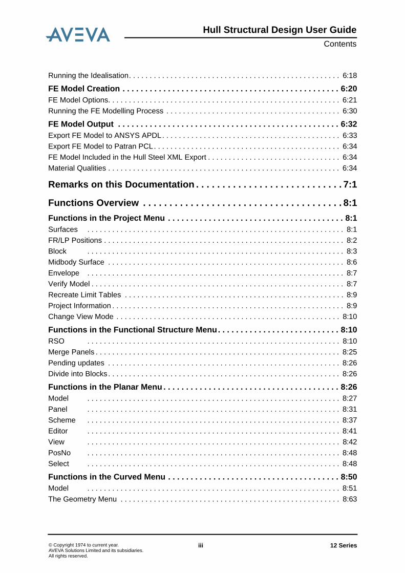
Figure 6:9. Idealized panel (enlarged)
In the other case a line in a stiffener end point perpendicular to the stiffener line will beintersected with other components. When the distance between the intersection point andthe stiffener end point is less than the given tolerance the stiffener end point will be snappedto the intersection point.
Example for perpendicular
12 Series 6:10© Copyright 1974 to current year.AVEVA Solutions Limited and its subsidiaries. All rights reserved.

Hull Structural Design User GuideFinite Element Model
Figure 6:10. Ordinary panel
Figure 6:11. Ordinary panel (enlarged)
12 Series 6:11© Copyright 1974 to current year.AVEVA Solutions Limited and its subsidiaries. All rights reserved.
Hull Structural Design User GuideFinite Element Model
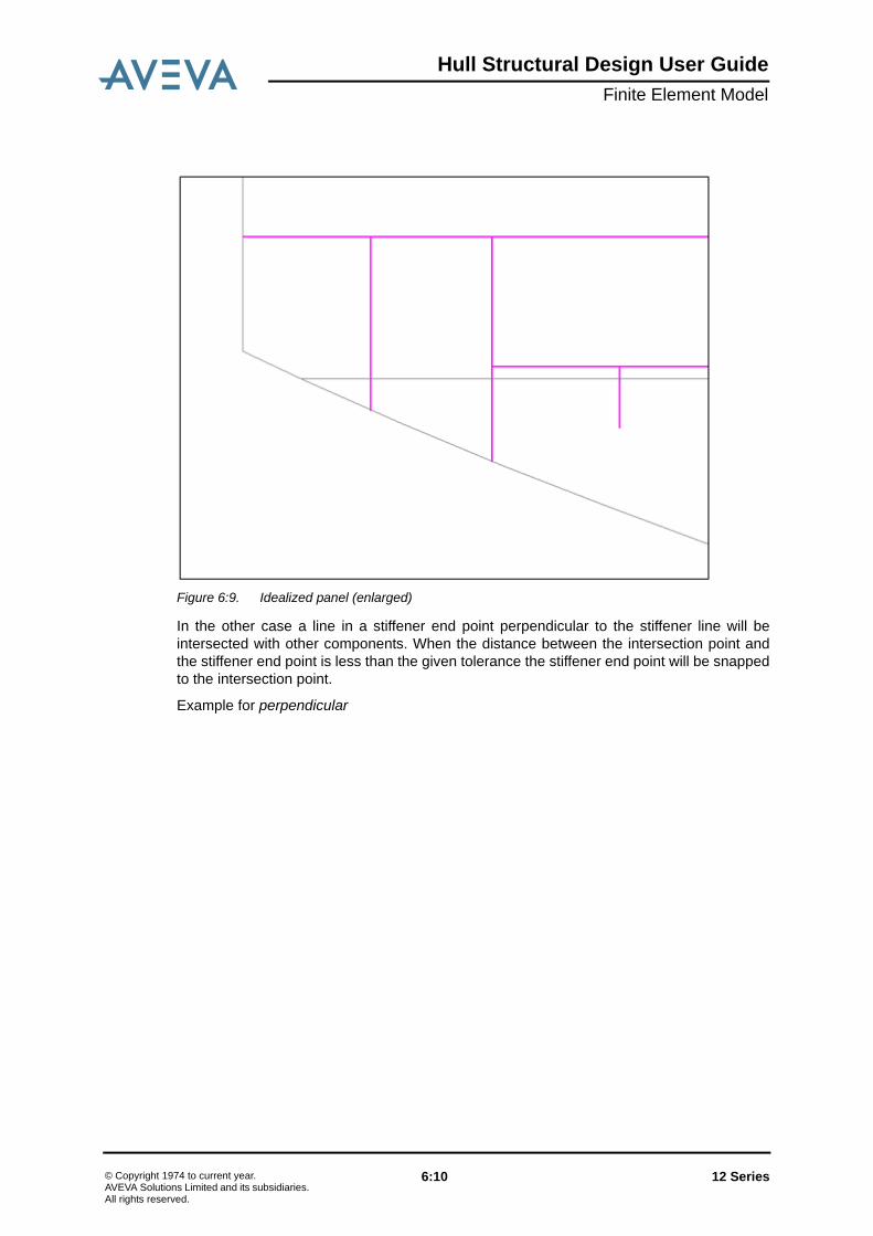
Figure 6:12. Idealized panel
12 Series 6:12© Copyright 1974 to current year.AVEVA Solutions Limited and its subsidiaries. All rights reserved.

Hull Structural Design User GuideFinite Element Model
Figure 6:13. Idealized panel (enlarged)
Cases, in which the distance is more than the keyed in value, are not handled in theidealisation but later in the FE modelling. The stiffener line will be extended and divides theshell element it belongs to.
Example:
Figure 6:14. Ordinary panel
12 Series 6:13© Copyright 1974 to current year.AVEVA Solutions Limited and its subsidiaries. All rights reserved.

Hull Structural Design User GuideFinite Element Model
Figure 6:15. Idealized panel
Figure 6:16. FE Model
- Effective Width Factor (Stiffeners, Girders as Panels)
A plate above a girder or stiffener acts as an additional flange. It increases the moment ofinertia when the girder is modelled as a beam. This theoretical part of the plate which isresponsible for the increasing of the moment of inertia is called effective width.
One method to take the effective width into consideration is to calculate it as a multiply of thethickness of the web plate. This factor (default 40) can be given in the idealization options.
12 Series 6:14© Copyright 1974 to current year.AVEVA Solutions Limited and its subsidiaries. All rights reserved.

Hull Structural Design User GuideFinite Element Model
- Lumped Beams
When this option is activated all stiffeners are lumped where main structural membersconnect as shown in the below picture. The geometric properties of the stiffeners willaccumulate to the surrounding geometry.
Figure 6:17. Example of plate and stiffener assemblies (Courtesy of Germanischer Lloyd)
This is done in the FE modelling. Stiffeners that are too small are already sorted out in theidealization process but all the remaining stiffeners are then lumped. This option can beused especially in global models to keep a coarse mesh.
• SwagesIn the global case swages are not modelled explicitly. The plate containing the swages ismodelled as shell element with orthotropic material based on the isotropic material of theplate.
… modified Young modulus perpendicular to the corrugated direction.
… Shear modulus in the plane of the plate.
12 Series 6:15© Copyright 1974 to current year.AVEVA Solutions Limited and its subsidiaries. All rights reserved.

Hull Structural Design User GuideFinite Element Model
In a local model the plate is again modelled as shell but with beams in the swage positions.The correct beam dimension is given by the user. The plate thickness is changed:
For detailed analyses the swages have to be modelled as they are.
• HolesHoles in the model are treated differently depending on their size. If they are small enoughthey will be removed already in the idealisation step. A hole in the idealized model with anarea bigger than the intended element size or intersecting a seam will be integrated into theplating as a free edge.
For the remaining holes they will lead to a thickness reduction of the shell elementcontaining them. There are two parameters that can be given to control thickness reduction:the absolute minimum thickness and the minimum percentage of the remaining material.When the resulting thickness is less than any of the given values the shell element will beremoved from the model.
The remaining material is measured along two directions taken from the orientation of thehole. Imagine we have the situation below:
Example:
l … plate length perpendicular to the swages.
… developed plate length.
12 Series 6:16© Copyright 1974 to current year.AVEVA Solutions Limited and its subsidiaries. All rights reserved.

Hull Structural Design User GuideFinite Element Model
Figure 6:18. Holes
First the hole's main direction is checked, this is the dashed line. Here the shell elementwidth is 1000 and the hole is 600 leaving 400. The remaining area factor is then 400/1000 =0.4 which is above the default factor (0.25). However in the direction perpendicular to themain direction (dashed-dotted line) the shell element width is 500 and the hole is 400leaving 100. The factor is then 100/500 = 0.2 that is below the limit and the shell element willbe removed! So if the hole weakens the shell element too much in any of these twodirections the shell element is removed.
Regarding the hole radii it is always removed in the FE model as it only contains straightlines. However in the idealized panels the radii always remain. The simplification of the holeradii in the FE model is controlled by the intended element size. If the size is small enoughthe radii will appear to be there even in the FE model, but if you zoom enough you will seethe lines.
• Unit SystemThe unit system in AVEVA Marine might differ from that one used to run FE analyses e.g.due to classification societies' requirements. In this case key points and properties have tobe converted to the new unit system before they are exported to e.g. an APDL file.
By clicking on the Unit System... button a dialogue will be opened in which you can set-upthe conversion factors. The conversion factors are stored together with the idealized block.They will be exported to the APDL file to let the user know in which unit system the inputdata was created. No further conversion is done in ANSYS itself.
• Functional Codes and DescriptionsSome functional descriptions defined while creating the panels have special meaning. E.g. agirder or web frame modelled as panel with two plates would be treated as an ordinary
12 Series 6:17© Copyright 1974 to current year.AVEVA Solutions Limited and its subsidiaries. All rights reserved.

Hull Structural Design User GuideFinite Element Model
panel and the plates always idealized as shells without taking special options for girderstaking into account. Using functional descriptions ensures that the correct idealizationoptions for the structural elements will be applied.
These functional descriptions are implemented so far:
6.1.4 Running the IdealisationTo start the idealisation process, click the OK button in the dialog. You will be notified if therewere any errors under the process. They should be carefully investigated becauseerroneous geometry may lead to unpredictable results in the FE modelling process.
Before running a new idealisation with the same idealized block, the old model has to bedeleted. You can do this in the FE geometry dialogue Analysis | Create FE Model. Selectthe block from the tree view and right-click, in the popup menu click on the item Delete.Confirm and the block and the idealized panels will be removed.
• Example for Idealisation with Different Types of Analysis
Figure 6:19. Original Panel
9901 Bracket
9902 Flange
9905 Girder/Web frame
The panel has to have a shape close to a rectangle and a single flange on asingle limit. All other limits except the two adjacent to the flange limit willform the beam trace.
9906 Transition girder (cambered decks)
9907 Stiffener
12 Series 6:18© Copyright 1974 to current year.AVEVA Solutions Limited and its subsidiaries. All rights reserved.

Hull Structural Design User GuideFinite Element Model
Figure 6:20. Idealized panel (global analysis, stiffeners as beams to be lumped in FE modelling)
Figure 6:21. Idealized panel (local analysis, stiffeners as beams)
12 Series 6:19© Copyright 1974 to current year.AVEVA Solutions Limited and its subsidiaries. All rights reserved.
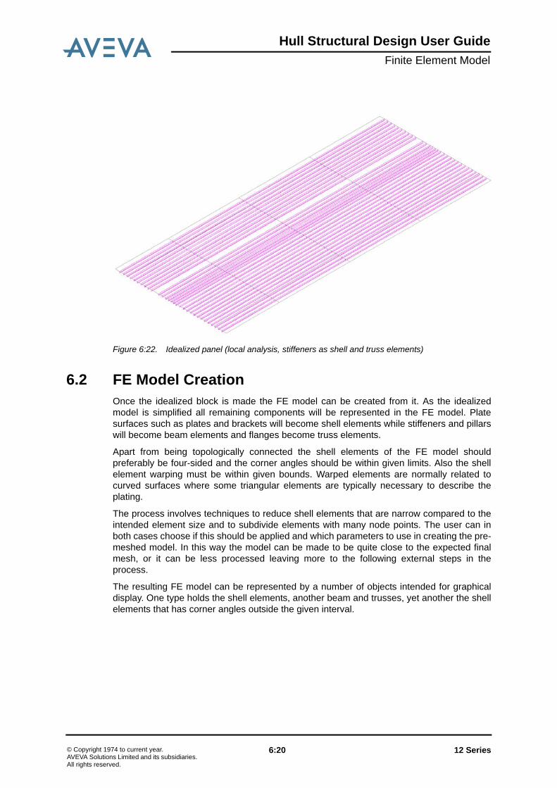
Hull Structural Design User GuideFinite Element Model
Figure 6:22. Idealized panel (local analysis, stiffeners as shell and truss elements)
6.2 FE Model CreationOnce the idealized block is made the FE model can be created from it. As the idealizedmodel is simplified all remaining components will be represented in the FE model. Platesurfaces such as plates and brackets will become shell elements while stiffeners and pillarswill become beam elements and flanges become truss elements.
Apart from being topologically connected the shell elements of the FE model shouldpreferably be four-sided and the corner angles should be within given limits. Also the shellelement warping must be within given bounds. Warped elements are normally related tocurved surfaces where some triangular elements are typically necessary to describe theplating.
The process involves techniques to reduce shell elements that are narrow compared to theintended element size and to subdivide elements with many node points. The user can inboth cases choose if this should be applied and which parameters to use in creating the pre-meshed model. In this way the model can be made to be quite close to the expected finalmesh, or it can be less processed leaving more to the following external steps in theprocess.
The resulting FE model can be represented by a number of objects intended for graphicaldisplay. One type holds the shell elements, another beam and trusses, yet another the shellelements that has corner angles outside the given interval.
12 Series 6:20© Copyright 1974 to current year.AVEVA Solutions Limited and its subsidiaries. All rights reserved.

Hull Structural Design User GuideFinite Element Model
6.2.1 FE Model Options
Figure 6:23. FE Model Options
A couple of options can be applied to prepare the FE model for the later use in FiniteElement Analysis software.
• Recreate FE ModelThis option is always to be checked if there is no FE geometry in the idealized block.
When the block already contains FE geometry you can check this option to recreate the FEmodel with different settings.
The following options can be applied without recreating the whole FE geometry.
• Divide Shell ElementsThis is the refinement process, basically to meet FEA software restrictions (number ofpoints, angles etc.).
The Divide shell elements option acts on all shell elements regardless of their origin. Theword shell may cause confusion here as in the FE context it refers to all thin surfaces asopposed to beam and truss elements while in our products shell is related to the sculpturedsurface. So the FE model shell elements come from curved and planar plating and maybealso from profile webs depending on detail level.
Max no of points is the maximum number of points that an area shall contain. In generalfour-sided elements are preferred especially when the model contains curved parts.
Min length factor means that, when you refine the FE geometry, the created lines will notbe shorter than ["Min length factor" x element size].
Angle is the angle between two neighbouring lines in an area. The angle deviation meansthat angles should preferably be right angular plus or minus the Angle deviation.
The relation between the criteria is that if a shell element has more points than Max no ofpoints an attempt is made so subdivide it. However in doing so it is made sure that lines
12 Series 6:21© Copyright 1974 to current year.AVEVA Solutions Limited and its subsidiaries. All rights reserved.
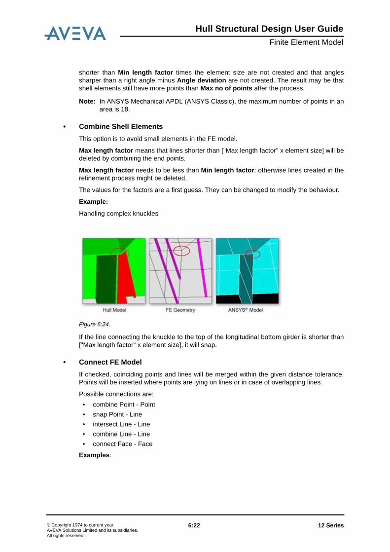
Hull Structural Design User GuideFinite Element Model
shorter than Min length factor times the element size are not created and that anglessharper than a right angle minus Angle deviation are not created. The result may be thatshell elements still have more points than Max no of points after the process.
Note: In ANSYS Mechanical APDL (ANSYS Classic), the maximum number of points in anarea is 18.
• Combine Shell ElementsThis option is to avoid small elements in the FE model.
Max length factor means that lines shorter than ["Max length factor" x element size] will bedeleted by combining the end points.
Max length factor needs to be less than Min length factor; otherwise lines created in therefinement process might be deleted.
The values for the factors are a first guess. They can be changed to modify the behaviour.
Example:
Handling complex knuckles
Figure 6:24.
If the line connecting the knuckle to the top of the longitudinal bottom girder is shorter than["Max length factor" x element size], it will snap.
• Connect FE ModelIf checked, coinciding points and lines will be merged within the given distance tolerance.Points will be inserted where points are lying on lines or in case of overlapping lines.
Possible connections are:• combine Point - Point• snap Point - Line• intersect Line - Line• combine Line - Line• connect Face - Face
Examples:
12 Series 6:22© Copyright 1974 to current year.AVEVA Solutions Limited and its subsidiaries. All rights reserved.

Hull Structural Design User GuideFinite Element Model
Figure 6:25. Connect FE Model
• Remove Transition StepThis is a special option for connection points of sloped panels and planar panels such ascambered decks. Generally in detailed and fine analysis, the cambered locations aremodelled as they are. However in global and local analysis, these locations will be handleddifferently. Using this settings, the user is able to select the tolerance where this step will beignored. Otherwise structure between cambered and non-cambered panels is to beidealized with truss elements at the element edges. The girder in the transition has to beindicated by a special functional code.
• Unwarp Shell ElementsIt allows the user to have control over shell element warping typically coming from theplating of sculptured surfaces. In general, a four sided face maybe somewhat warped butfaces with more than four sides need to be planar. In order to get desirable meshes withoutwarnings and errors, a maximum warping factor should be defined within a certain limit. Thewarping factor is the height deviation divided by the square root of the area.
12 Series 6:23© Copyright 1974 to current year.AVEVA Solutions Limited and its subsidiaries. All rights reserved.

Hull Structural Design User GuideFinite Element Model
Figure 6:26. Example for different warping factors
It may be that elements are created with too sharp angles as a result form the unwarpingprocess. The unwarping is done by subdividing the warped element along lines created byconnecting boundary points. The requirement to remove warping is stronger than the anglecriteria as a warped element cannot be used while an element with a sharp angle is justundesired.
• Images for Visualisation and Error CheckingThe resulting FE model can be checked in AVEVA Marine. When you run the FE modelleryou have the possibility to create an FE image for shell, beam and truss elements. Thatmeans the Shell element image will contain all the polygons coming from platesrepresenting the later shell elements. The Beam and Truss element image contain allpolylines coming from stiffeners, flanges, pillars… representing the later beam and trusselements.
Shell, Beam and Truss element image represent the model data being exported on FEmodel output. There are some more images available for error checking purposes. Freeedge and Angle image are options that can be created by choosing the according item fromthe idealized block's context menu.
All images can be created without recreating the whole FE geometry. The FE images can bedisplayed by dragging and dropping from the Design Explorer or by inserting the model withthe FE Image criteria checked.
• Shell Element ImageIf checked, an FE image will be created containing all areas representing shell elements.
The resulting object will get the name _FGSxxx with xxx=name of the idealized block (e.g._FGSTEST for the idealized block named TEST). The shell polygons are drawn as simpleclosed polylines (no shading).
When the model doesn't contain any shell elements the _FGSxxx object will not be created.
12 Series 6:24© Copyright 1974 to current year.AVEVA Solutions Limited and its subsidiaries. All rights reserved.
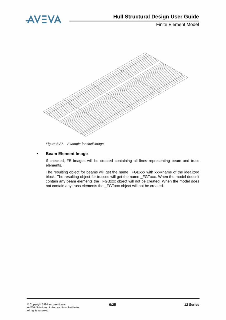
Hull Structural Design User GuideFinite Element Model
Figure 6:27. Example for shell image
• Beam Element ImageIf checked, FE images will be created containing all lines representing beam and trusselements.
The resulting object for beams will get the name _FGBxxx with xxx=name of the idealizedblock. The resulting object for trusses will get the name _FGTxxx. When the model doesn'tcontain any beam elements the _FGBxxx object will not be created. When the model doesnot contain any truss elements the _FGTxxx object will not be created.
12 Series 6:25© Copyright 1974 to current year.AVEVA Solutions Limited and its subsidiaries. All rights reserved.

Hull Structural Design User GuideFinite Element Model
Figure 6:28. Example for beam image (on top of shell image)
Figure 6:29. Example for truss image (on top of shell image)
• Available from the Idealized Block's Context Menu;
- Angle Image
If checked, an FE image will be created containing lines in places where the angle deviationin the FE model is smaller than the value given in the FE model settings.
12 Series 6:26© Copyright 1974 to current year.AVEVA Solutions Limited and its subsidiaries. All rights reserved.

Hull Structural Design User GuideFinite Element Model
Small angles should be avoided but especially in the curved parts this is not alwayspossible. Triangles need to be used to break down warped shell elements (i.e. the points ofthe shell elements are not all in the same plane which can not be handled by FEA software).
The angle between two lines sharing one endpoint is calculated and compared with thevalue given in "Angle deviation".
The resulting object will get the name _FGAxxx with xxx=name of the idealized block
When the model does not contain any angle problems the _FGAxxx object will not becreated.
Figure 6:30. Example for angle image (on top of shell image)
- Element Image
Shell, Beam and Truss element image will be created.
- Free Edge Image
An FE image will be created containing the lines which belong to only one area. They occurfor example at panel boundaries when the panel is not connected to another object or inholes. Free edges in other places might be an indication of a missing connection betweenmodel parts.
The resulting object will get the name _FGFxxx with xxx=name of the idealized block
When the model does not contain any free edges the _FGFxxx object will not be created.
12 Series 6:27© Copyright 1974 to current year.AVEVA Solutions Limited and its subsidiaries. All rights reserved.

Hull Structural Design User GuideFinite Element Model
Figure 6:31. Example for angle image (on top of shell image)
- Line Image
An FE image will be created containing all lines.
The resulting object will get the name _FGLxxx with xxx=name of the idealized block.
When the model doesn't contain any lines the _FGLxxx object will not be created.
- Point Image
An FE image will be created containing all points as they would be exported on FE modeloutput.
The resulting object will get the name _FGPxxx with xxx=name of the idealized block.
When the model doesn't contain any points the _FGPxxx object will not be created.
• Other Functions Available from the Contextmenu
- Statistics
The Statistics dialogue might give an idea of the data amount of the pre-meshed model.
Example:
12 Series 6:28© Copyright 1974 to current year.AVEVA Solutions Limited and its subsidiaries. All rights reserved.

Hull Structural Design User GuideFinite Element Model
Figure 6:32.
Minimum block limit, maximum block limit:
This is the bounding box that has been used to select the model objects for idealisation. Thenumber seen in the example represent the default case that no box has been explicitly set.
Type of analysis, Element size:
These are the settings that have been used for idealising the block.
Number of objects:
This is the number of plane panels and surfaces contributing to the model.
Number of polylines:
This is the number of all polylines - not only beams and trusses - in the model. A lot of themcome from e.g. shell curves and panel trace curves to create the curved parts of the modelwithout being a part of the final model itself.
Number of surface elements:
Number of beam elements:
Number of truss elements:
This is the number of the actual data elements to be exported on FE model output..
Number of lines:
12 Series 6:29© Copyright 1974 to current year.AVEVA Solutions Limited and its subsidiaries. All rights reserved.

Hull Structural Design User GuideFinite Element Model
This is the number of all lines defined by start and end point index referred by polylines andareas.
Number of points:
This is the number of all points in the model. They are exported on FE model output andreferred by shell, beam and truss elements.
- Check
This function checks the FE model and informs the user about errors like intersecting orcoinciding lines.
It is mainly used for advanced error investigation.
- Dump
This function writes detailed information about the selected item in the console window.Depending on the level in the tree this might be the geometry of one selected polygon or alllines, polygons and properties in a panel. On block level the geometry and properties of allpanels and surfaces is dumped.
It is mainly used for advanced error investigation.
- Delete
The selected idealized block and all related objects will be removed.
- Delete Images
Only the images created for the selected idealized blocks will be removed.
6.2.2 Running the FE Modelling ProcessIn general the topological connection of plane panels with the hull, decks and other curvedobjects determines the portion(s) of the curved surface(s) that shall be part of the FE model.The FE modeller calculates a bounding box of these panel trace curves and intersects thesurface by the principal planes forming the box. A boundary polygon is created from theintersection curves (blue) and refined by curves representing shell profiles, seams and soon. Adding the panel trace curves to this grid guarantees the topological connectionbetween the surfaces and the inner structure. Material properties for the curved parts arefetched from shell plates and shell stiffeners belonging to shell profiles.
Due to the great variety of surface shapes it is not always possible to find and assemblethose polygon boundaries automatically and it might be necessary to interactively indicatethe portion of the surface that is part of the FE model.
It is therefore recommended to have at least one view to create and/or select some seamsor shell curves that shall create a closed boundary polygon in the surface(s). Theintersection points of the curves must not be more than 5 x element size far away from theFE model box limits.
Portside and starboard are handled separately, so when the model is extending over CLthere need to be a curve near CL as well to limit both parts of the model in centreline.
After these preparations the FE Model dialog can be opened, the necessary settings madeand the FE model built by pressing the OK button. When user support is needed do asdescribed in the following section.
12 Series 6:30© Copyright 1974 to current year.AVEVA Solutions Limited and its subsidiaries. All rights reserved.
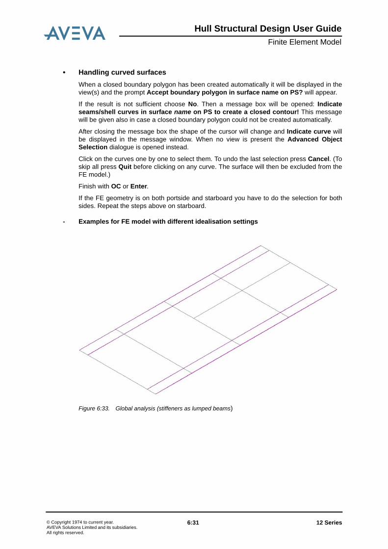
Hull Structural Design User GuideFinite Element Model
• Handling curved surfacesWhen a closed boundary polygon has been created automatically it will be displayed in theview(s) and the prompt Accept boundary polygon in surface name on PS? will appear.
If the result is not sufficient choose No. Then a message box will be opened: Indicateseams/shell curves in surface name on PS to create a closed contour! This messagewill be given also in case a closed boundary polygon could not be created automatically.
After closing the message box the shape of the cursor will change and Indicate curve willbe displayed in the message window. When no view is present the Advanced ObjectSelection dialogue is opened instead.
Click on the curves one by one to select them. To undo the last selection press Cancel. (Toskip all press Quit before clicking on any curve. The surface will then be excluded from theFE model.)
Finish with OC or Enter.
If the FE geometry is on both portside and starboard you have to do the selection for bothsides. Repeat the steps above on starboard.
- Examples for FE model with different idealisation settings
Figure 6:33. Global analysis (stiffeners as lumped beams)
12 Series 6:31© Copyright 1974 to current year.AVEVA Solutions Limited and its subsidiaries. All rights reserved.

Hull Structural Design User GuideFinite Element Model
Figure 6:34. Local analysis (stiffeners as beams)
Figure 6:35. Detailed analysis (stiffeners as shell and truss elements)
6.3 FE Model OutputThe FE model can be exported in the following ways:
• creating an ANSYS command file in APDL format• creating a Patran session file in PCL format
12 Series 6:32© Copyright 1974 to current year.AVEVA Solutions Limited and its subsidiaries. All rights reserved.

Hull Structural Design User GuideFinite Element Model
• included in the Hull Steel XML Export
6.3.1 Export FE Model to ANSYS APDLThis option creates an ANSYS command file in APDL format. The APDL file can beprocessed in ANSYS Mechanical APDL (ANSYS Classic) where the geometry, elementproperties and materials are created for further meshing and analysis.
Figure 6:36. Create ANSYS Input File
Using the default settings will export the element types SHELL181, BEAM188 and LINK180.When element types with midnodes are chosen, SHELL281, BEAM189 and LINK180 areexported. It is possible to use different types for the planar and the curved parts of the modelbut the user should be aware that this will effect the order in which the parts of the modelhave to be meshed in ANSYS (see ANSYS help for detailed information).
Using the old ANSYS element types will export SHELL63, BEAM44 and LINK8. This is notrecommended because these elements are no longer documented by ANSYS.
• ANSYS WorkbenchIt is not possible to import the APDL file directly into ANSYS Workbench. But there is a linkbetween ANSYS Classic and ANSYS Workbench so that the meshed model can be used inWorkbench.
• Import the model into ANSYS Classic and mesh it.• From the command line run CDOPT, ANF to setup the output format.• Run CDWRITE, COMB, filename, CDB. This will write both geometry and database
information to one file. For more information and options see CDWRITE in the ANSYSHelp.
• Open ANSYS Workbench and create an empty project.• Click Link to ANSYS CDWRITE Input… and open the cdb file you created before.• Select the filename. In ANSYS CDWRITE Tasks click New FE Model. This will read all
information from the cdb file.
12 Series 6:33© Copyright 1974 to current year.AVEVA Solutions Limited and its subsidiaries. All rights reserved.

Hull Structural Design User GuideFinite Element Model
6.3.2 Export FE Model to Patran PCLThis option creates a Patran session file in PCL format. This session file can then be playedpreferably in batch mode in Patran creating a database file containing all geometry withmaterial and element properties for further meshing and analysis.
The following settings and element types are used in the Patran export:
6.3.3 FE Model Included in the Hull Steel XML ExportIn the Hull Steel XML Export it is possible to select idealized blocks for export. An additionaloption allows the user to export the according FE model as well, if present.
The FE model part of the Hull Steel XML Export contains the node points and the shell,beam and truss elements with properties as well as references to the original ship modelpanels.
6.3.4 Material QualitiesMaterial qualities are not explicitly handled in AVEVA Marine but they are mandatory to runthe finit element analysis.
Material properties can be defined in an XML file and imported by choosing "XML | Import |Hull Steel Import" from the menu in Structural Design. That creates a material object whichis used to export material properties to the 3rd party software.
Example File:
<?xml version="1.0" encoding="UTF-8"?>
<Ship xmlns:xsi="http://www.w3.org/2001/XMLSchema-instance" xsi:noNamespaceSchemaLocation="M:\xml\schema\Export\HullPanel.xsd" Version="1.3">
<Material Grade="A" Density="7840" YoungsModulus="206E3" PoissonRatio="0.3" YieldStress="220" UltimateStress="360"/>
<Material Grade="A22" Density="7840" YoungsModulus="206E3" PoissonRatio="0.3" YieldStress="220" UltimateStress="360" ThermalExpansionCoefficient="0.012"/>
<Material Grade="A27" Density="7790" YoungsModulus="205E3" PoissonRatio="0.3" YieldStress="270" UltimateStress="490" ThermalExpansionCoefficient="0.011"/>
<Material Grade="A32" Density="7790" YoungsModulus="205E3" PoissonRatio="0.3" YieldStress="320" UltimateStress="510" ThermalExpansionCoefficient="0.011"/>
Analysis Code: "MSC.Nastran"
Analysis Type: "Structural"
Element types: "Shell" with options "Thin", "Homogenous" and "Standard Formulation"
"Beam" with option "General Section (CBEAM)"
"Rod" with options "General Section", "Standard Formulation"
12 Series 6:34© Copyright 1974 to current year.AVEVA Solutions Limited and its subsidiaries. All rights reserved.

Hull Structural Design User GuideFinite Element Model
<Material Grade="A25" Density="7910" YoungsModulus="205E3" PoissonRatio="0.3" YieldStress="250" UltimateStress="430" ThermalExpansionCoefficient="0.011"/>
</Ship>
12 Series 6:35© Copyright 1974 to current year.AVEVA Solutions Limited and its subsidiaries. All rights reserved.

Hull Structural Design User GuideFinite Element Model
12 Series 6:36© Copyright 1974 to current year.AVEVA Solutions Limited and its subsidiaries. All rights reserved.

Hull Structural Design User GuideRemarks on this Documentation
7 Remarks on this Documentation
The rest of this documentation consists mainly of detailed comments on most of thefunctions of the application. There are other aspects that currently are less carefullycovered. Since some functionality of Structural Design is common to functionality of PlanarHull Modelling and Curved Hull Modelling detailed information may often be gathered fromthe documentation of these two modules.
An example is the default file. Structural Design has a default file of its own by namesj700.sbd. The content of this file is mainly a merge of the default files of Planar andCurved Hull Modelling. For the meaning of the default parameters, please refer to thedetailed description of them in these documents.
12 Series 7:1© Copyright 1974 to current year.AVEVA Solutions Limited and its subsidiaries. All rights reserved.

Hull Structural Design User GuideRemarks on this Documentation
12 Series 7:2© Copyright 1974 to current year.AVEVA Solutions Limited and its subsidiaries. All rights reserved.

Hull Structural Design User GuideFunctions Overview
8 Functions Overview
The functions of Structural Design consist of a mixture of Structural Design specificfunctions and hull functions that are common to all hull modules. In addition, the completeset of Drafting functions are available. This documentation will focus on the StructuralDesign specific functions, while functions common to all hull modules are more brieflydescribed, but with references to the documentation in the specific hull module. All Draftingfunctions are described in AVEVA Marine Drafting.
8.1 Functions in the Project MenuThe functions in the Project menu are used to make settings valid for a whole project. Thefunctions cover the definition of frame and longitudinal positions, the definition and handlingof block objects, the definition of a first simple midbody surface, tools to verify the hull modelto be topologically correctly defined and a tool to recreate limit tables used within AVEVAMarine.
Figure 8:1. The functions in the project menu.
8.1.1 Surfaces
Purpose: To register/view the name of the main hull form, deck form andadditional surfaces.
Prerequisites: A surface (hull form) has to be released from Lines or Surface/Compartment before it can be registered for use by StructuralDesign.
12 Series 8:1© Copyright 1974 to current year.AVEVA Solutions Limited and its subsidiaries. All rights reserved.

Hull Structural Design User GuideFunctions Overview
8.1.2 FR/LP Positions
Instructions: The Register Surfaces dialog presents a list of surfaces whichhave been released from Lines or Surface/Compartment or havebeen registered by Initiate Hull Standards. The information is listedin the following columns:
• RegisteredIndicates whether the surface is registered for use byStructural Design. If a surface is not registered, then it can beregistered by selecting the checkbox. The number followingthe checkbox is the surface reference number used by thedefaults parameter SURFACES (see Hull / Planar Modelling /User’s Guide / Default File of Planar Hull Modelling /Parameters / General Purpose).
• NameName of the surface.
• SuffixThis is normally a one or two character string which is used asa suffix when creating Longitudinals, Transversals, ShellStiffeners and Shell Profile Trace Curves. The main hull formdoes not require a suffix. All other surfaces must have aunique suffix. Specify the suffix my clicking in the cell andtyping it in.
• TypeThe purpose of the surface which can be one of Main Hull,Main Deck, Shell or Deck. Choose a purpose for a surface byselecting the cell and choosing an item from the drop downlist. There can only be one Main Hull and one Main Deck
• SourceWhich application created the surface. This is forinformational purposes and cannot be changed.
• DesignThe name of the design from which the surface was released.This is for informational purposes and cannot be changed.
• Delete SurfaceFrom this dialog surfaces can also be deleted by selecting asurface in the list and then pressing the delete button in thedialog.
Options: None
Result: Any surfaces which are selected by their checkbox are stored inthe Hull Reference Object
Purpose: To view/change the frame and longitudinal positions.
Prerequisites: None.
12 Series 8:2© Copyright 1974 to current year.AVEVA Solutions Limited and its subsidiaries. All rights reserved.

Hull Structural Design User GuideFunctions Overview
8.1.3 BlockThe Block menu contains functions for the creation and manipulation of block objects asshown below:
• Block - Edit
Instructions: Choose frame, horizontal or vertical longitudinal positions. Thepositions are given as start, step and end values. Also thecoordinate values are given as start, step and end values. If any ofthe end values are omitted it will be calculated automatically. If twoend values are given the program will make sure they arematching by recalculating one of them if necessary.
The function also allows the user to define additional positiontables to be used in cases where this is required, typically when aship contains two distinct parts with different positions (e.g. a steellower part and an aluminium upper part). The different tables aredefined within a geographical area and the modelling functionsand ruler functions will consider this. However, presentingcoordinates with the dimensioning function will always use thedefault table for translation.
See also Hull Model Concepts / Co-ordinate Systems and RelativePositions
Options: Not available.
Result: The frame and/or longitudinal positions are defined.
Purpose: To create, modify, recreate, copy or delete Design and ProductionBlocks.
Prerequisites: None.
12 Series 8:3© Copyright 1974 to current year.AVEVA Solutions Limited and its subsidiaries. All rights reserved.

Hull Structural Design User GuideFunctions Overview
• Block - Recreate
• Block - Create from CSV
Instructions: All existing blocks are presented in a tree-like dialogue. An existingblock can be selected and modified. Properties that can bemodified are the nominal limits and the offset value at each limit.Limiting Objects, Stored Planes, Reference Surface Objects andSurfaces, can be given to get the exact shape of the block. If alimiting object is selected, the nominal limit is adjusted based onthe extents of the generated block volume. Finally, colour,symmetry and type of block can be updated. The changes areapplied by using the function Save Block Data within the dialogue.
The functions New, Copy, Recreate and Delete are activated bythe right-button on the mouse. When recreating blocks, the usercan select to recreate only the currently selected block or allblocks.
Options: Not available.
Result: Blocks may have been created, modified, recreated or deleted.
Purpose: To recreate a block based on the block definition of nominal limitsand limiting objects.
Prerequisites: None.
Instructions: Pick blocks to be recreated in the current drawing.
Options: Not available.
Result: Picked blocks are recreated.
Purpose: To create or update blocks with data given in a CSV file.
Prerequisites: None.
12 Series 8:4© Copyright 1974 to current year.AVEVA Solutions Limited and its subsidiaries. All rights reserved.

Hull Structural Design User GuideFunctions Overview
• Block - Extract to CSV
Instructions: The CSV file is selected within a dialogue and all blocks in the fileare created or updated according to the given data.
File Format:
<Type(D or P)>, <Name,> <Nom. Aft>,<Nom. Stbd>,<Nom. Bot>,<Nom. For>,<Nom. Port>,<Nom. Top>,<Encl. Block>,<Offset Aft>,<Offset Stbd>,<Offset Bot>,<Offset For>,<Offset Port>,<Offset Top>,<Limit Aft>,<Limit Stbd>,<Limit Bot>,<Limit For>,<Limit Port>,<Limit Top>,<Sym>,<Colour>
• The first row in the file is treated as comment and will not beprocessed.
• The Type character (D or P) is given if it is a Design Block or aProduction Block that shall be created.
• The nominal coordinates of the block are given as X, Y and Zcoordinates. Frame and LP positions are possible to use.
• The Enclosing Block name is the name of the design blockthat encloses the production block to be created. Only neededwhen creating Production Blocks and when the project alsocontains Design Blocks.
• Offset values are given in mm.• The limiting objects are given with a prefix defining the type
followed by the name of the limiting object. The prefix areSUR/ for surfaces, RSO/ for reference surfaces and PLA/ forstored planes.
• Symmetry definition is given as Yes or No.• The colour code is given as an integer.
If a block description is given in the file and the block alreadyexists, then the block is updated only in case the block is actuallychanged.
Options: Not available.
Result: Blocks are created and updated.
Purpose: To extract the current block structure into a CSV file
Prerequisites: None.
Instructions: When function is selected, a file is created on SB_SHIPDATA andis made available via the Log Viewer. The format of the file isspecified within the function Block - Create from CSV.
Options: Not available.
Result: The file is created
12 Series 8:5© Copyright 1974 to current year.AVEVA Solutions Limited and its subsidiaries. All rights reserved.

Hull Structural Design User GuideFunctions Overview
8.1.4 Midbody Surface
Purpose: To quickly create a parallel mid-body surface directly fromStructural Design.
Prerequisites: None.
Instructions: A dialogue is presented, with instructions to add basic informationto create the surface as specified below:
• Aft extent of the midbody surface• Forward extent of the midbody surface• Beam• Depth• Rise Of Floor,• Flat Of Keel, • Bilge Type (None, Flat, Circular)• Bilge Radius (for Circular bilges)• Bilge Y Point (for Flat bilges)• Bilge Z Point (for Flat bilges)• Tumble In Y Point• Tumble In Z Point• Tumble Out Y Point• Tumble Out Z Point
Options: Not available.
Result: The surface is stored in database and registered in the hullreference object (hullref).
12 Series 8:6© Copyright 1974 to current year.AVEVA Solutions Limited and its subsidiaries. All rights reserved.

Hull Structural Design User GuideFunctions Overview
8.1.5 Envelope
8.1.6 Verify Model
Purpose: To create or modify an Envelope by combining a number ofsurfaces and RSOs into a closed volume. Envelopes are used asthe outer boundary when e.g. creating or modifying an RSO.
Prerequisites: The surfaces and RSOs needed to create the envelope must exist.
Instructions: A dialogue is presented containing 3 lists, one presenting availableenvelopes, one presenting boundaries within each envelope andone containing all limits that can be used when defining envelopes.
A new envelope is created by right-clicking in the envelope list andby selecting function New in the pop-up menu. The surfaces andRSOs that shall form the closed volume are fetched from the listwith limits. Select and use right-click to get a drop-down menuwhere function Add can be used. An alternative way to selectlimits is to use the function Pick in Dwg. By using this function,surfaces and RSOs can be selected in the current drawing. Usethe Option function to toggle between the two limit types.
An existing envelope can be changed by selecting it in theenvelope list and add or remove envelope boundaries. Remove aboundary by selecting it and use right-click to get a drop-downmenu where function Remove is used. Boundaries are added inthe same way as when creating a new envelope.
When an envelope is created or modified, the function SaveEnvelope shall be used to create and save the envelope.
An envelope can be deleted by selecting it in the envelope list anduse right-click to get a drop-down menu where Delete can beactivated.
Options: There are no options available to this function.
Result: Envelopes are created, modified or deleted.
Purpose: To get a smooth and correct transition from Structural to DetailDesign, using the Block Splitting function, it is essential that themodel is correctly defined regarding all topological dependencies.This function verifies that this is the case, otherwise warningmessages are issued.
Prerequisites: None.
Instructions: Any number of Blocks and Panels can be selected via thefunction dialogue. The Verify operation is executed via the LogViewer where the results of this operation can be obtained.
Options: Not available.
12 Series 8:7© Copyright 1974 to current year.AVEVA Solutions Limited and its subsidiaries. All rights reserved.

Hull Structural Design User GuideFunctions Overview
Result: The model is checked and warnings are presented in caseswhere there is a need for actions to get a correct model. Beloware given a examples of warnings and recommended actions tobe performed:
The name QF9801-LB8700A1__3 may be too long. Should be maximum 17 characters
A panel name can be at most 19 characters as prefix (twocharacters) are added to create e.g. a topology object andsuffixes are used in e.g. block divide when creating new panels(at least two characters) and then the objects on PLDB andPROFDB are derived from the panel name. If it is over 17characters there is a small risk that the maximum length will beexceeded but over 19 a greater risk for e.g. a stiffener on abracket on a panel as a profile object. If the panel name is longerthan 19 characters it should be renamed.
Panel QF9801-T214A2, boundary -! CAT-object does not exist
One of the objects referred to from the boundary definition doesnot exist. It may be a curve object or another panel. Make surethe correct CGDB is used. Make sure that referred objects havenot been deleted after panel generation.
Panel QF9801-TMT213A2, boundary -! The outer contour could not be recreated with notches/cutouts
The outer contour including cutout geometry can not be created.It may be that the profiles referred to are no longer intersected bythe current panel or they do not exist any more. Generate thepanel interactively to check the cutout definition.
Panel QF9602-TG215F1, missing topology object!
The topology object corresponding to the given panel does notexist in the topology databank connected. Make sure the correctREFDB is used. Update the topology database with the utilityprogram sj903.
Panel QF9801-TBA213D2, bracket group #7 -> object QF9602-L6300A2__1 - missing in topology object for QF9801-TBA213D2!
The panel has a bracket referring another object, but thereference is not noted in the topology object of this panel.Generate and store the panel to update the topology object.
Panel QF9801-TG207A2, boundary group #3 -> object QF9800-TBA201D2, flange group #5 - invalid reference in topology object for QF9801-TG207A2!
The topology object contains a reference that does not exist inthe panel. Generate and store the panel to update the topologyobject.
12 Series 8:8© Copyright 1974 to current year.AVEVA Solutions Limited and its subsidiaries. All rights reserved.
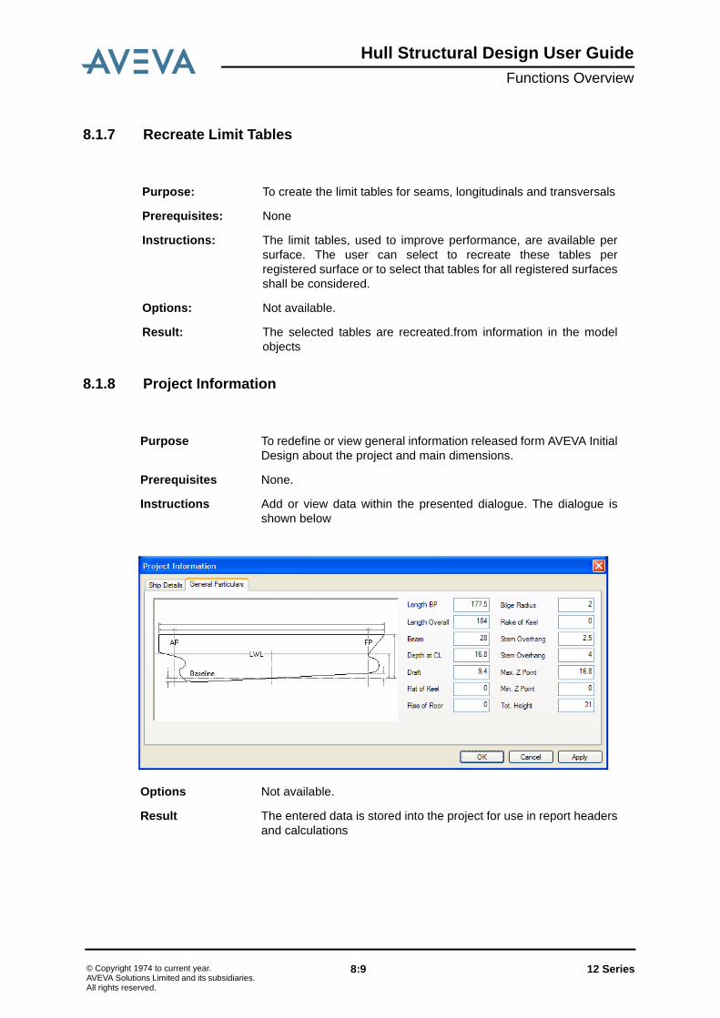
Hull Structural Design User GuideFunctions Overview
8.1.7 Recreate Limit Tables
8.1.8 Project Information
Purpose: To create the limit tables for seams, longitudinals and transversals
Prerequisites: None
Instructions: The limit tables, used to improve performance, are available persurface. The user can select to recreate these tables perregistered surface or to select that tables for all registered surfacesshall be considered.
Options: Not available.
Result: The selected tables are recreated.from information in the modelobjects
Purpose To redefine or view general information released form AVEVA InitialDesign about the project and main dimensions.
Prerequisites None.
Instructions Add or view data within the presented dialogue. The dialogue isshown below
Options Not available.
Result The entered data is stored into the project for use in report headersand calculations
12 Series 8:9© Copyright 1974 to current year.AVEVA Solutions Limited and its subsidiaries. All rights reserved.
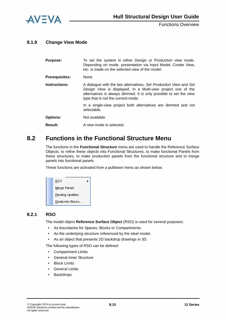
Hull Structural Design User GuideFunctions Overview
8.1.9 Change View Mode
8.2 Functions in the Functional Structure MenuThe functions in the Functional Structure menu are used to handle the Reference SurfaceObjects, to refine these objects into Functional Structures, to make functional Panels fromthese structures, to make production panels from the functional structure and to mergepanels into functional panels.
These functions are activated from a pulldown menu as shown below.
8.2.1 RSOThe model object Reference Surface Object (RSO) is used for several purposes:
• As boundaries for Spaces, Blocks or Compartments.• As the underlying structure referenced by the steel model.• As an object that presents 2D backdrop drawings in 3D.
The following types of RSO can be defined:• Compartment Limits• General Inner Structure• Block Limits• General Limits• Backdrops
Purpose: To set the system in either Design or Production view mode.Depending on mode, presentation via Input Model, Create View,etc. is made on the selected view of the model.
Prerequisites: None
Instructions: A dialogue with the two alternatives, Set Production View and SetDesign View is displayed. In a Multi-view project one of thealternatives is always dimmed. It is only possible to set the viewtype that is not the current-mode.
In a single-view project both alternatives are dimmed and notselectable.
Options: Not available
Result: A new mode is selected.
12 Series 8:10© Copyright 1974 to current year.AVEVA Solutions Limited and its subsidiaries. All rights reserved.

Hull Structural Design User GuideFunctions Overview
Note: The steel model can only be located in RSO of type Compartment Limit or GeneralInner Structure.
The RSO menu contains sub-functions in a pulldown menu as shown below.
The functions in this submenu are described below.
• Key In
Purpose: To create an RSO by keying in its position and by selecting limitingobjects.
Prerequisites: The envelope to be used must exist as an object in the data base.
Instructions: Key in position and select plane and limiting objects, either from adrop-down list or by picking in the 2D canvas. Define the type ofRSO by picking from a list within the dialogue.
Options: None.
Result: The RSO is created as a limited plane surface. The RSO is limitedby the given envelope and by the given limits.
12 Series 8:11© Copyright 1974 to current year.AVEVA Solutions Limited and its subsidiaries. All rights reserved.

Hull Structural Design User GuideFunctions Overview
• Sketch 2D
Purpose: To create and modify an RSO by the use of 2D drafting tools.
Prerequisites: The envelope to be used must exist as an object in the data base.The function operates on two of the drafting views; the SymbolicPlanar View and on Backdrop Views.
Instructions: The function operates on two of the drafting views; the SymbolicPlanar View and on Backdrop Views.
When the function is activated the following dialogue window ispresented:
The functions Draw allows the user to sketch a polyline (possiblyaided by a grid definition). When defined, an RSO is createdlimited by the closest surface or RSO at the line end points.
The function Select allows the user to select already definedgeometry in a view. The selected geometry is used for the RSOcreation in the same way as when using function Draw.
The function Trim allows the user to trim an RSO. An RSO (andthe end to be trimmed) is selected first, and secondly a surface oranother RSO to be used as trimming object.
The drop down list contains envelopes that can be selected andapplied on the created RSOs.
The generated RSOs are automatically named using the symboliccoordinate of the plane coordinate. If no symbolic translation of thecoordinate can be made, then a prefix X, Y or Z is added. Anyminus (-) character is exchanged with the character N and anyplus (+) character is exchanged with character P. Finally and indexpostfix can be added in case more than one RSO is added in thesame plane. The automatic name can be changed by using one ofthe options (see below) or by renaming it using the function RSO >Rename.
The type of the RSO is always set to General Inner Structure. Thiscan be changed in functions Properties or Edit Shape.
12 Series 8:12© Copyright 1974 to current year.AVEVA Solutions Limited and its subsidiaries. All rights reserved.
Hull Structural Design User GuideFunctions Overview
• From Backdrop
• From Panel
Options: When activating the Grid, a grid distance in U and V direction mustbe given. The grid is considered when using the Draw function
When Mirror Copy is activated, the RSO definition is mirroredwhere possible. Typically, a cambered deck only needs to bedefined on one side of the centre line.
When Verify Name and Limits is activated, the automaticallygenerated name and the selected limits of the RSO to be createdis presented and made possible to change.
Result: The RSO is created or modified.
Purpose: To generate an RSO by the use of a backdrop view and to store allgeometry within this view as marking on the created RSO.
The function will only create the RSO if the backdrop is defined ina principle plane. The plane and the coordinate (keyed in whencreating the backdrop view) are used to generate the RSOgeometry. If a surface exists and an intersection between thesurface and the plane is successful, the RSO is created using thisintersection curve. If this is not the case, the RSO limits aregenerated from the window of the selected backdrop view.
An RSO that is created in a principle planes X and Y, will be limitedby the surface and the upper deck. If an RSO named WEATHERexists, this one is used as the upper limit. If it does not exists, thenthis RSO is created automatically. The function fetches a suitableZ value from the intersection curve between the plane and thesurface.
Prerequisites: A view generated as a Backdrop must exist in the current drawing.Backdrops are generated using the function Backdrop in the Toolsmenu.
Instructions: A Backdrop view shall be indicated and a RSO name shall begiven.
Options: Not available.
Result: The created RSO of type Backdrop with marking is stored on thedata bank.
Purpose: To create an RSO from existing panels.
Prerequisites: The involved panels must exist.
12 Series 8:13© Copyright 1974 to current year.AVEVA Solutions Limited and its subsidiaries. All rights reserved.

Hull Structural Design User GuideFunctions Overview
• Recreate
• Edit Shape
Instructions: This function, is used to create or update an RSO from existingpanels in cases where no internal surfaces are already available.First a number of panel instances are picked, and then the name ofthe RSO can be defined in a dialog together with an option toupdate the involved panels to depend on the RSO for theirlocation. The extension of the RSO is fetched from the panelboundaries.
The RSO is composed of a number of connected, limitedsubplanes. It can also contain references to plane panels. Fromthe other end a plane panel can refer to an RSO for its position inspace. This makes it possible to refer to the RSO rather than thepanel in a number of cases. The advantage of referring an RSO isthat the reference is stable even if the RSO initially contains jumbopanels that are later subdivided into panels for detail design.
Options: Not available.
Result: The RSO is created.
Purpose: To recreate the geometry of an RSO in cases where the limitingobjects or the envelope has changed. In case the RSO is createdfrom panels, then also any panel changes are considered.
Prerequisites: The RSO and the objects on which the RSO depends must exist.
Instructions: By picking the RSO the recreation is done. The recreated RSO willexchange all instances of the RSO in the current drawing.
Options: By using the options button, all RSO’s within a view can beselected to be recreated.
Result: The RSO is recreated.
Purpose: To modify the shape of an RSO via table values for profiles.
Prerequisites: The surface to be used as an envelope must exist as an object inthe data base.
12 Series 8:14© Copyright 1974 to current year.AVEVA Solutions Limited and its subsidiaries. All rights reserved.

Hull Structural Design User GuideFunctions Overview
Instructions: When the function is activated the following dialogue window ispresented:
The dialogue provides possibility to change the shape of an RSOvia grid input for profiles and their definition points.
There is also a possibility to change the limits, envelope andposition of an RSO. Limits are changed either by selecting from adrop - down list or picked in the current drawing.
The shape of the RSO is defined by profiles (cross-sections).These profiles are described in the profile tab of the dialog.
Each profile defines a cross-section of the shape via absoluteposition of the profile and profile definition points.
All profiles have the same number of definition points.
12 Series 8:15© Copyright 1974 to current year.AVEVA Solutions Limited and its subsidiaries. All rights reserved.

Hull Structural Design User GuideFunctions Overview
Addition, removal or insertion of profile is facilitated by the Add,Del and Ins buttons in the Profile group. The Del and Ins buttonswork based on the currently selected cell.
In a similar fashion, the addition, removal and insertion of profilepoints is facilitated by the Add, Del and Ins buttons in the Profilepoint group.
Each time a change is made to the grid describing the profiles, thechange is saved in the profile editing history. Each step in thathistory is available to the user via the forward and backwardbuttons in the Profile history group. If the Profile history backbutton is used, then the current history point is moved and eachchange in the grid will insert new profile history entry. This isdifferent to the well established Undo/Redo concept, where eachchange after Undo will erase all the Redo steps.
The buttons also display the number of available steps in thecorresponding direction.
The presentation of the data in the grid can be adjusted via theShow translated and Show absolute coordinates checkboxes.
The Show translated checkbox converts all possible absolutevalues to translated FP/LP position strings.
The Show absolute coordinates checkbox converts all deltavalues to absolute coordinates based on the current position valuefor the RSO.
When editing values in the grid the user must be aware of thecurrent setting i.e. - if the Show absolute coordinates checkboxis selected, all input from the user will be interpret as absolutecoordinate values.
12 Series 8:16© Copyright 1974 to current year.AVEVA Solutions Limited and its subsidiaries. All rights reserved.

Hull Structural Design User GuideFunctions Overview
The main requirement when describing the shape of an RSO isthat the individual RSO faces are not knuckled, keeping the four-sided faces flat. There are various options in the Edit shapedialogue to help the user with this requirement.
Every time a value is changed in the profile definition grid, there isa potential possibility that the requirement is not met. Toautomatically adjust after each value change the Keep profileparallel radio button can be selected. This will instruct thedialogue to change related values on the edited profile, so theshape of the edited RSO does not contain any faces with knuckles.The algorithm can be instructed to try and adjust the next line (theline of the profile formed from the point being edited and the nextpoint in the current profile) or the previous line. Via Modify nextline and Modify previous line radio buttons.
In some cases a more drastic change in the shape of the RSOmay be necessary. Then the Single cell edit radio button shouldbe selected. This will switch off the algorithms for keeping theprofiles in accordance with the requirements for the shape. Aftersuch a change it is a good idea to select a cell in the grid thatbelongs to the profile that should not be changed, and then clickon the Iron button. The Iron button will change the rest of theprofiles and make them fulfil the compliance with the mainrequirement.
For sa imple overview of changed values, the grid control will mark(with darker background colour) all cells changed as a result of‘Ironing’. Similar change in appearance will be noticed when cellvalue was changed by the "anti-knuckle" algorithm.
If the desired result was not obtained with the Iron button, orduring any step in during modifying the shape of the RSO, a clickon the <- button in the Profile history can revert to the grid valuesbefore that change.
Options: Not available.
Result: The RSO shape is modified according to the profile descriptions.
12 Series 8:17© Copyright 1974 to current year.AVEVA Solutions Limited and its subsidiaries. All rights reserved.

Hull Structural Design User GuideFunctions Overview
• Copy
Purpose: To copy an existing RSO.
Prerequisites: The limiting objects of the copied RSO must exist as objects in thedata base.
Instructions: A dialogue is presented to the user.
The name of the new RSO, its position (relative from the original orabsolute) and type of RSO should be given. In case the selectedRSO type is block limit, then the created RSO can be madetopologically dependent of the original RSO, by ticking the KeepConnection box.
Multiple copies can be made by using a repetition term in thePosition field. The syntax of the repetition term is:
<Start value>[(Step)<End value][+-Offset]
In case multiple copies are requested, the naming of RSOs aremade in the following way:
• If name XXX is given as target name and multiple copies arerequested, then the copied RSOs are named XXX, XXX1,XXX2, ...XXXn
• if name XXX10 is given as target name and multiple copiesare requested, then the copied RSOs are named XXX10,XXX11, XXX12, ...XXXn
• If name XXX10(10) is given as target name and multiplecopies are requested, then the copied RSOs are namedXXX10, XXX20, XXX30, ...XXXn
Options: Not available.
Result: The RSO is copied and recreated into the new positions.
12 Series 8:18© Copyright 1974 to current year.AVEVA Solutions Limited and its subsidiaries. All rights reserved.

Hull Structural Design User GuideFunctions Overview
• Move
• Rename
• Change Envelope
Purpose: To move an RSO into a new position
Prerequisites: The limiting objects of the copied RSO must exist as objects in thedata base.
Instructions: Key in the offset distance to be used.
Options: Not available.
Result: The RSO is moved and recreated in the new position
Purpose: To change the name of an existing RSO
Prerequisites: None
Instructions: Key in the new unique name of the RSO
Options: Not available
Result: The RSO is renamed. Panels located in the renamed RSO areupdated with the new location and the boundary conditions ofRSOs that are topologically dependent of the renamed RSO areupdated.
Note: That all other topological dependences are currently notupdated, e.g. hull panels using the RSO as boundary limitneeds to be manually updated.
Purpose: To move RSOs defined in one envelope into another envelope
Prerequisites: None
12 Series 8:19© Copyright 1974 to current year.AVEVA Solutions Limited and its subsidiaries. All rights reserved.

Hull Structural Design User GuideFunctions Overview
Instructions: The following dialogue is presented to the user:
Select the envelope in the drop-down list in which RSOs shall bechanged. Available RSOs will be presented. Then select targetenvelope in the drop-down list for target envelopes. Mark RSOsand use the Add button to move the RSOs. Use the Removebutton to change the selection. When ready, then apply thechanges either by using the Apply button or the OK button (whichalso will close the dialogue).
Options: Not available.
Result: The RSOs are moved into and regenerated in their new envelope.
12 Series 8:20© Copyright 1974 to current year.AVEVA Solutions Limited and its subsidiaries. All rights reserved.

Hull Structural Design User GuideFunctions Overview
• Properties
Purpose: To add modelling properties to the RSOs available on thedatabank SB_TID, in order to prepare them for automaticgeneration of steel.
To copy, create, edit, move or recreate RSOs.
Prerequisites: When releasing items from Surface/Compartment to the PIM(menu item: File / Release / Design) the following issues shouldbe observed to ensure that correct limits are produced (to allowautomatic steel generation).
• A Main Deck should be defined as part of the envelopedefinition. This may be a deck definition or a more generalsurface. Whichever is used should be marked for release (atick appearing in the Design column of the Full View tree); asit will be referenced by any Reference Surface Objects,RSOs, (i.e. transverses, longitudinals or decks) that are alsomarked for release.
• RSOs may also reference the bounding shell surface (inSurface/Compartment this is the parent envelope). The nameof this surface is determined by checks in the following order:
1. If the envelope is marked for Design release, its ID isused.
2. If the barehull of the envelope is marked for Designrelease, its ID is used.
3. If the barehull used a Hull Form (i.e. a dml file) for itsdefinition, then the dml name is used.
Note: The dependency of the barehull on a released dml file isset when the dml file is used to create a surface (menuitem: File \ Use \ Hull Form…).
Note: Any of these surfaces must also be registered through thefunction Project / Surfaces or via Initiate Hull Standards.
4. If none of the above items are found, then the limit will becalled ìHULL_NOT_KNOWNî.
The functional descriptions are based on the standard set-up ofthese descriptions. If these are not displayed properly, then checkthe functional descriptions and make additions according to thisdocumentation. Alternatively, the current standard object can bedeleted (with risk of loosing any added information). The next timeany access is made to the object, it will automatically be recreatedwith the standard descriptions.
12 Series 8:21© Copyright 1974 to current year.AVEVA Solutions Limited and its subsidiaries. All rights reserved.
Hull Structural Design User GuideFunctions Overview
• Generate Panels
Instructions: The function brings in all the RSOs from the databank andpresents them in a tree-type dialogue.
RSOs of types General Limits, Block Limits and Backdrop arepresented below specific named nodes in the tree browser withinthe dialogue. For these types of RSOs, general information ispresented together with an editable field for the RSO type.
For RSO of type Compartment Limit or General Inner Structurealso structural properties, such as functional descriptions,materials, profile data and end cut information can be added to acomplete RSO or individually on faces of an RSO. The RSOs fromwhich panels shall be generated automatically, should be markedusing a tic box in the dialogue. The properties of a RSO aredescribed in Extracting RSO Information in Chapter Batch Utilities.
The end cut information is based on the set-up of the standardobject for stiffener connections. See Hull / Setup andCustomisation / Profiles in AVEVA Marine.
Bracket can currently be added to transversal bulkheads, using thebracket instance handling of AVEVA Marine. Set-up of thisinstance handling is further described in Hull / Setup andCustomisation / Brackets.
This function also contains a possibility to generate new RSOs orcopy, move, recreate, delete or edit the shape of existing onessimply by using the right-click-button within the dialogue.
Options: Not available.
Result: The RSOs will be stored with the updated information.
Purpose: To automatically generate a first attempt of steel panels based onthe available RSOs with modelling properties added.
Prerequisites: Only RSOs with information that steel shall be generatedautomatically will be considered and a functional description isdefined describing the function of the RSO (see functionProperties).
Instructions: The function brings in all the RSOs from the databank, andextracts the ones that are ordered to be generated steel on.
Once all these RSOs are extracted, the panels are generatedstarting with decks and then all other remaining panels. Panels willbe placed in a block named JUMBO, which will be created if notavailable. The names of created panels will be JUMBO-><RSOname without the prefix>_<face number of the RSO>
The following panel components are added depending of thefunctional description of the RSO:
12 Series 8:22© Copyright 1974 to current year.AVEVA Solutions Limited and its subsidiaries. All rights reserved.

Hull Structural Design User GuideFunctions Overview
Decks (9000 - 9099):
Generated with plate material and stiffeners in the horizontallongitudinal positions. No stiffeners are placed in positions wherethe deck is intersected by any RSO representing a longitudinalbulkhead.
Transversal Bulkheads (9200 - 9299):
Generated with plate material. Stiffeners are generated in thehorizontal longitudinal positions. No stiffeners are placed inpositions where the RSO is intersected by any other RSOrepresenting a longitudinal bulkhead. If the RSO is limited by adeck, the stiffeners are connected to this decks stiffeners andbrackets are created if asked for.
Longitudinal Bulkheads (9100 - 9199):
Generated with plate material. Stiffeners are generated in thevertical longitudinal positions. No stiffeners are placed in positionswhere the RSO is intersected by any other RSO representing adeck. Stiffening is added (if requested via the RSO properties) todecks and bulkhead using the frame and longitudinal positions. Noprofiles are placed in intersections between these panel types.
General Web Frame Member (9400):
The intention of this RSO is to generate panels depending on theintersecting RSOs. The current implementation handles somepossible cases:
• Floor Panels are created if the RSO is intersected by a RSOrepresenting the Inner Bottom (9010), the Double Bottom(9011) or the Tank Top (9012) and if this deck is intersectingeither the main surface, a Girder (9300) or the Inner Side(9102), then the floor panel is created with the samecomponents as the transversal bulkhead described above.
• Hopper Transverse Webs are created if the creation of FloorPanel succeeded and if the RSO is intersected by a HopperTank Sloping (9104) . No stiffening are made on these panels.
• Vertical Web panels are created if the creation of Floor Paneland the Hopper Transverse Web Panels succeeded and if theRSO is intersected by an Inner Side (9102)
RSOs with other functional descriptions:
The current implementation will generate a panel with plate material only.
Cutouts:
Cutouts are added to all panel types. The definition depends on the setup for automatic setting of cutouts. See Hull / Setup and Customization / Cutouts and Clips / Automatic Setting of Cutouts.
12 Series 8:23© Copyright 1974 to current year.AVEVA Solutions Limited and its subsidiaries. All rights reserved.

Hull Structural Design User GuideFunctions Overview
• Disconnect
• RSO - Delete
Options: In case the option for Fibre Reinforced Plastics (FRP) is used, thelogical variable SBH_GRP_LAM shall be assigned with defaultlaminate code.
Result: The generated panels are stored and presented in existing views.If no views are available, a new view is created in the currentdrawing.
Purpose: To disconnect panels from an RSO and to translate the locationof the referenced panels.
Prerequisites: None
Instructions: The user is asked to indicate either an RSO or a paneldepending on selection mode (see Options below). The selectedpanels are all depending on a RSO for their position. Thedisconnect operation will update the location definition for thepanels and remove the reference from the RSO to the panel. Thenew panel location will be derived from the panel plane and willbe either a position along one of the principal axes, or threepoints.
Internal references to the RSO (within e.g. the Boundary of thepanel) are not translated. These changes must be mademanually by the user.
Options: Selecting the Option button will toggle between selection of aRSO or a panel.
Result: The selected panels and the RSO are updated.
Purpose: To delete an RSO and to translate the location of the referencedpanels
Prerequisites: None
Instructions: This function is used to delete an RSO from the database afterconfirmation. It will also be removed from the picture. It may bethat plane panels are depending on the RSO for their position. Insuch a case the user is given an additional control questionbefore deletion.
The location definition for the panels that refer to the RSO isupdated. The new location will be derived from the panel planeand will be either a position along one of the principal axes, orthree points.
12 Series 8:24© Copyright 1974 to current year.AVEVA Solutions Limited and its subsidiaries. All rights reserved.

Hull Structural Design User GuideFunctions Overview
8.2.2 Merge Panels
Options: Not available.
Result: The RSO is deleted and connected panels updated.
Purpose: To merge a number of panels into one panel.
Prerequisites: The panels to merge must exist.
Instructions: Pick the panels to merge from the picture. The merging betweenpanels can take place provided that they share a common limit andthat the limits surrounding the shared limit have equal definitions.Also the panels must be defined in the same plane and havecompatible symmetry codes.
In the dialog, give the name of the new panel and the name of theblock.
Options: If the checkbox Only check if panels can be merged is markedany problem merging the given panels is reported to the user. Ifsuccessful, the scheme file of the temporary resulting panel isshown. No panel or block name need to be given as no real panelis created.
Result: The boundaries of the panels are merged, but also plates withedges along the coinciding limits. Also seams, stiffeners andflanges with ends meeting at the coinciding limits are combined ifpossible.
For panel components to be combined they must share the maincharacteristics such as type, dimension, direction, inclination etc.
If more than two panels are given all panels are compared witheach other recursively, including the new panels resulting from themerge of two previous ones, until no more merges are possible.Only one panel should remain, otherwise the function fails with anerror message.
In a multi-view project with Design Panels and Production Panels,only Design Panels can be merged by this function. If the mergedDesign Panels have connected Production Panels, a Block Seamis created replacing the merged limit.
Production Panels can not be merged as the Block Seam referredby from the coinciding limits may connect to limits on otherProduction Panels as well. However by using the function Planar >Panel > Remove Seam, all Production Panels connecting to thisBlock Seam can be merged two and two.
12 Series 8:25© Copyright 1974 to current year.AVEVA Solutions Limited and its subsidiaries. All rights reserved.

Hull Structural Design User GuideFunctions Overview
8.2.3 Pending updates
8.2.4 Divide into Blocks
8.3 Functions in the Planar MenuBelow follows a short description of the functions used to create and view the planar parts ofthe ship, e.g. the inner structure such as bulkheads and girders. More detailed informationcan be found in the documentation Hull / Planar Modelling.
The corresponding pull-down menus are shown below.
Purpose: To update Design/Production panels when its corresponding panelhas been modified.
Prerequisites: Only meaningful in a Multi-View project.
Instructions: Make a selection containing panels. These panels will then bechecked for pending updates and also updated after userconfirmation. The updated panels are left activated.
Options: If no selection is made before invoking the function, the user isprompted to pick panels. If Options is used then, the generalselection tools appears.
Result: Any pending updates are performed.
Purpose: In Multi-View projects:
To create Production Panels from Design Panels. It can also beused to subdivide a Design Block into smaller Design Blocks.
In Single-View (ordinary) projects:
To subdivide blocks into smaller units.
Prerequisites: The block to divide and the target blocks must exist. If ProductionPanels are created Production Blocks must be connected to theDesign Block.
Instructions: See Structural Design / Block Division
Options: See Structural Design / Block Division
Result: See Structural Design / Block Division
12 Series 8:26© Copyright 1974 to current year.AVEVA Solutions Limited and its subsidiaries. All rights reserved.

Hull Structural Design User GuideFunctions Overview
Figure 8:2. The Planar Model Menu.
8.3.1 ModelThe functions within the Model group of functions are all functions to add, modify or deletestructure items (.e.g. stiffeners, holes, etc) to a planar panel. Below is given a description ofeach individual function within this group.
Figure 8:3. The functions in the Model menu.
• Create
Purpose: To create components in a plane panel.
Prerequisites: Only one panel can be active at a time. If there is no active panel,panel activation is prompted prior to performing this function.
Instructions: Due to the volume of information required for this function,reference must be made to the Hull Planar Modelling Users'Guide.
Options: Not available.
Result: Sub-menu is displayed
12 Series 8:27© Copyright 1974 to current year.AVEVA Solutions Limited and its subsidiaries. All rights reserved.

Hull Structural Design User GuideFunctions Overview
• Modify
• Edit
Purpose: To modify existing components in a panel using the input schemesyntax.
Prerequisites: The panel containing the components to be modified must beactive. If there is no active panel, panel activation is promptedprior to performing this function. The required components mustbe displayed in the hull view.
Instructions: Indicate and confirm the components to be modified in the hullview. After component selection, the scheme statement of thegroup will be displayed in an editor window. Note that if multiplecomponents are defined in the same group, the entire group willreceive the same modifications. Group Divide can be used toavoid this.
Options: If activated when prompted to indicate component, a menu toselect component type appears. This is useful in graphicallymessy situations.
Result: The component or group of components will be changed asspecified in the statement. The panel, scheme and view will beupdated.
Purpose: To modify existing components in a panel using the input schemesyntax.
Prerequisites: The panel containing the components to be modified must beactive. If there is no active panel, panel activation is promptedprior to performing this function. The required components mustbe displayed in the hull view.
Instructions: Indicate and confirm the components to be modified in the hullview. After component selection, the scheme statement of thegroup will be displayed in an editor window. Note that if multiplecomponents are defined in the same group, the entire group willreceive the same modifications. Group Divide can be used toavoid this
Options: If activated when prompted to indicate component, a menu toselect component type appears. This is useful in graphicallymessy situations.
Result: The component or group of components will be changed asspecified in the statement. The panel, scheme and view will beupdated.
12 Series 8:28© Copyright 1974 to current year.AVEVA Solutions Limited and its subsidiaries. All rights reserved.
Hull Structural Design User GuideFunctions Overview
• Divide
• Split STI
Purpose: To separate a group of components into two groups.
Prerequisites: A panel must be active. If there is no active panel, panel activationis prompted prior to performing this function. The panel mustcontain multiple components belonging to a group (i.e.corresponded by a single statement in the scheme). The group tobe divided must be displayed in the required view, otherwiseselection is not possible.
Instructions: Indicate the group of components to be divided, then indicate andconfirm the components to be removed from the group.
Options: Not available.
Result: A new group is created containing all of the removed components.The components not selected will remain in the original group.
Purpose: To split stiffeners at the intersection with a given line or a selectedintersecting component. The selection of stiffeners to be split canbe made as the complete group of stiffeners or an individualstiffener within a group.
Prerequisites: A panel must be active. If there is no active panel, panel activationis prompted prior to performing this function.
Instructions: Indicate the stiffener or the group of stiffeners to be split. Choose aline definition from the displayed sub-menu. Indicate of the locationof the line to split the group. If preferred, components may be usedto split stiffeners. The types of components that can be used tosplit stiffeners are any of the types: another stiffener, a seam, ahole or a panel.
Options: Options can activated in two situations:
1. When selecting stiffeners to be split, the Option button is usedto toggle between group selection and individual stiffenerselection.
2. When selecting intersecting element, the Option button isused to toggle between line definition and selection of anintersecting component..
Result: The selected stiffeners are split. If a group of stiffeners areselected and an intersecting component is selected instead of aline, then it may be the case that not all stiffeners in the groupintersect the component. In this situation, the stiffeners that do notintersect are left in the original group, and a new group with theupdated stiffeners is inserted.
12 Series 8:29© Copyright 1974 to current year.AVEVA Solutions Limited and its subsidiaries. All rights reserved.
Hull Structural Design User GuideFunctions Overview
• Modify STI End
• Delete
Purpose: This function is used to modify stiffener ends. A stiffener group oran individual stiffener is selected. One of the ends is modified tostop at either a line or an existing component. As for the Split_STIfunction the component can be any component on the panel that astiffener end can connect to or it can be another intersecting panel.A third option is to pick the panel boundary in which case thestiffener will end at the panel edge.
Prerequisites: A panel must be active. If there is no active panel, panel activationis prompted prior to performing this function.
Instructions: Indicate a stiffener or a group of stiffeners to be modified. Thegiven pick point is also used to select which end that shall bemodified. This may not always be possible (e.g. picking in a crosssection view) and a question is then asked about which end to bemodified. Choose a line definition from the displayed sub-menuand make the line definition. If preferred, existing components maybe selected instead
Options: Options can activated in two situations:
1. When selecting stiffeners to be modified, the Option button isused to toggle between group selection and individualstiffener selection.
2. When selecting intersecting element, the Option button isused to toggle between line definition and selection of anintersecting component..
Result: The selected stiffeners are modified
Purpose: To delete a complete group of components or an individualcomponent from a planar panel. The corresponding views andscheme will be updated accordingly.
Prerequisites: A panel must be active. If there is no active panel, panel activationis prompted prior to performing this function.
Instructions: Indicate and confirm the selection (group or individual component)to be removed.
Options: The Option button is used to toggle between selection of a groupof components or individual components
Result: The delete operation will be performed.
12 Series 8:30© Copyright 1974 to current year.AVEVA Solutions Limited and its subsidiaries. All rights reserved.

Hull Structural Design User GuideFunctions Overview
8.3.2 PanelThe functions within the Panel group of functions are all functions to manipulate the planarpanel as one unit, e.g. to copy, rename, delete etc. Below is given a description of eachindividual function within this group.
Figure 8:4. The functions in the Panel menu
• Copy
Purpose: To make copies of existing panels at new locations.
Prerequisites: One or more panels should be active in hull views on the currentdrawing. If there are no active panels, panel activation isrequested before copying can commence.
Instructions: A form will appear on the screen. On this form, the names andblocks of the currently active panels are already filled in. Enter thenames and blocks of the new panels to be created. Alternatively,select AS OLD or NEW MODULE to reduce manual input. ASOLD will copy the names and modules of the existing activepanels into the fields for the new panels. NEW MODULE requiresa module number to be entered in the field at the bottom of theform, which will then substitute the modules in the existing panelnames. Direction buttons are provided to navigate through theform if the number of active panels exceeds one page.
12 Series 8:31© Copyright 1974 to current year.AVEVA Solutions Limited and its subsidiaries. All rights reserved.

Hull Structural Design User GuideFunctions Overview
• Move
After new panel names have been entered and checked in theform, a second form will appear, which requires a location to bedefined for the new panels. Enter a new absolute location for thepanels, or specify an incremental move along the X, Y or Z-axis.The Relative position button on the location form activates anincremental move. Incremental moves may be entered as a lineardistance from the original position or as a number of Frame orLongitudinal positions. A positive number (e.g. 10000 or +FR10)will move the panels forward on the X-axis, towards port of the Y-axis or up on the Z-axis. A negative number (e.g. -5000 or -LP10)will move the panels aft on the X-axis, towards Starboard on the Y-axis or down on the Z-axis. Multiple duplication is possible, eitherby repeating the copy command on the new panels, or by usingrepetition syntax.
Options: Not available
Result: New panels will be generated at the specified location. Thecoordinate references and name references will be updated in thepanel definition data. References to hull curves, frames andlongitudinal positions are also updated to correspond to the newlocation. Hull views are also updated, but view limits must bemodified to include the new panels otherwise the panels will not bedisplayed when the view is updated.
Purpose: To move an existing panel to a new location.
Prerequisites: One or more panels should be active in hull views on the currentdrawing. If there are no active panels, panel activation is promptedbefore moving can commence.
Instructions: A form will appear, which requires a new location to be defined forthe active panels. Enter a new absolute location for the panels, orspecify an incremental move along the X, Y or Z-axis. The'Relative position' button on the location form activates anincremental move. Incremental moves may be entered as a lineardistance from the original position or as a number of Frame orLongitudinal positions. A positive number (e.g. 10000 or +FR10)will move the panels forward on the X-axis, towards port of the Y-axis or up on the Z-axis. A negative number (e.g. -5000 or -LP10)will move the panels aft on the X-axis, towards Starboard on the Y-axis or down on the Z-axis.
Options: Not available.
Result: Active panels will be moved to the new location. They will beupdated with new location information and references to hullcurves, frames and longitudinal positions are updated tocorrespond to the new location.
12 Series 8:32© Copyright 1974 to current year.AVEVA Solutions Limited and its subsidiaries. All rights reserved.

Hull Structural Design User GuideFunctions Overview
• Rename
• Split
Purpose: To rename, change block or change functional description ofexisting panels.
Prerequisites: One or more panels should be active in hull views on the currentdrawing. If there are no active panels, panel activation isrequested before the function can commence.
Instructions: When one or several panels are activated, a form will appear onthe screen for each activated panel. On this form, the name ofthe panel can be changed, a new block can be picked from adrop-down list and a new functional description can be picked.
Options: Not available
Result: The active panels will be changed according to the actions fromthe user. All panels referring are updated regarding their namereferences.
Purpose: To split a panel, or group of panels, into two separate panels by aplane or a RSO.
Prerequisites: One or more panels should be active in hull views on the currentdrawing. If there are no active panels, panel activation is promptedbefore splitting can commence.
Instructions: Indicate a line signifying the plane to use for splitting the panels. Aform will be displayed requiring new names to be provided for thepanels that will be created by this function. The form also providesthe facility to create AVEVA Marine panels from non-reflectedpanels and vice-versa.
Options: Options may be selected when prompted to indicate a line,offering a menu from which to choose the splitting method. Panelsmay be split by picking an existing line in the view, by defining aco-ordinate value along the X, Y or Z-axis, by selecting anintersecting panel or a RSO.
Result: Two new panels are created. The old panel is discarded from thedata bank after user confirmation. If an intersecting panel wasused to split the active panel, the thickness of the intersectingpanel is considered when creating the new panels.
12 Series 8:33© Copyright 1974 to current year.AVEVA Solutions Limited and its subsidiaries. All rights reserved.

Hull Structural Design User GuideFunctions Overview
• Remove Seam
• Modify Symm
Purpose: To remove a seam and combine adjacent components two by two.
Prerequisites: One or more panels should be active in hull views on the currentdrawing. If there are no active panels, panel activation is promptedbefore splitting can commence.
Instructions: Indicate the seam to remove. The plates on either side of the seamare combined into one. Also the stiffeners and flanges crossing theseam are combined two and two. For the combination to bepossible the number of components in the groups on either side ofthe seam need to be equal. Also the dimensions and the positionsmust be equal. If differences are detected for non-critical data theuser is asked to select from one of the two components.
Options: Not available
Result: The indicated seam is removed. The components on either side ofthe seam are combined if possible.
Purpose: To generate two side specific (port and starboard) panels from anactive symmetric panel.
Prerequisites: One or more symmetric panels should be active in the currentdrawing. If there are no active panels, panel activation is promptedbefore modification can commence.
Instructions: The panels are created automatically and the original panel isdeleted from the databank. Make certain the new panels arestored to prevent any loss of data
Options: Not available
Result: The new panels with side specific codes are generated.
12 Series 8:34© Copyright 1974 to current year.AVEVA Solutions Limited and its subsidiaries. All rights reserved.

Hull Structural Design User GuideFunctions Overview
• Topology
• Compare
Purpose: This function can be used to visualize the dependencies betweenmodel objects using the topology information within the planepanel as a basis. Given a model object both the objects defining itand the objects depending on it can be shown.
Furthermore the objects shown can be listed and activated (onlyplane panels). Once the plane panels are activated they can bee.g. regenerated to adapt to any changes in the defining objectsusing the Recreate function described above.
Prerequisites: None
Instructions: Multiple objects can be given initially and the resulting objects canbe used for the next search. This means that the dependenciescan be visualized repeatedly, level-by-level. To benefit from thisfunction the model must be created using topological referencesrather than pure coordinates whenever possible.
Also other objects than plane panels can be picked initially,provided that they are used in the definition of a panel. This is validfor e.g. shell curves and surfaces.
Options: Using the Option button will give the user a possibility to key in themodel object name (e.g. a panel, a RSO, a surface, etc.) instead ofindicating it in the drawing.
Result: The activation of panels can be made using the stored topologyinformation of AVEVA Marine
Purpose: Suppose a situation where a big panel (e.g. a complete deck) hasbeen generated in the early design phase. Further suppose thatthis big panel has been broken down into panels of production(e.g. block) size. In the detail design stage details are added andchanges are made (e.g. of dimensions and qualities), also in partsthat have been derived form the original big panel. To make certainthat these changes do not jeopardize the strength calculationsmade during the basic design stage, a function has beendeveloped to assist the designer in comparing the original bigpanel with the derived panels of production size.
This function compares a number of component types (plates,stiffeners, welded flanges, pillars and brackets) regardingdimensions and quality. Found differences will be displayed bothgraphically and in a list. To identify a difference, AVEVA Marinemust be able to find a component in the big panel in the samelocation as a component of the same type in the part panel.Additional requirements for stiffeners are that they have to be onthe same side of the panel and have the same inclination.
12 Series 8:35© Copyright 1974 to current year.AVEVA Solutions Limited and its subsidiaries. All rights reserved.

Hull Structural Design User GuideFunctions Overview
• Knuckled
In the view of the part panel the following colours are used toindicate differences/no differences compared to the big panel:
• The dimensions are smaller or the quality differs: Red • The dimensions are bigger and the quality is the same: Blue • The dimensions and quality are the same: Green • No corresponding component found on the big panel: White
For the big panel: • No corresponding component found on the part panel: White
The identity of the component will also be displayed to make iteasier to find the corresponding row in the list of differences that isalso displayed. This difference list contains the component identity,the dimensions and quality of matching components of both thepart panel and big panel.
Prerequisites: None
Instructions: Select the big panel and the part panel to be compared.
Options: Using the Option button will give the user a possibility to key in thename of the big panel or the part panel instead of indicating
Result: The differences are displayed in the drawing (using colours asdescribed above) and in a dialogue window on the screen. Thedifferences optionally be output as a CSV list.
Purpose: This function is used to create a knuckled panel from a number ofordinary panels.
The symmetry code of the main knuckled panel is derived from thecontained panels. If all panels are symmetrical, the knuckled panelwill be symmetrical. If any of the panels is over-CL, or if panels aredefined on both sides of the CL, the knuckled panel will be definedas over-CL. In other cases the knuckled panel will be defined oneither PS or SB.
Prerequisites: The ordinary planar panels that will be used to create the knuckledpanel must exist.
Instructions: One or more panels should be selected and information aboutname of knuckled panel, the block it shall belong to and bendingtype must be given.
Options: None available.
Result: The given panels are converted into sub-panels, removed from theblock they belong to and are included in the created knuckled mainpanel.
12 Series 8:36© Copyright 1974 to current year.AVEVA Solutions Limited and its subsidiaries. All rights reserved.

Hull Structural Design User GuideFunctions Overview
• Recreate
• Delete
8.3.3 SchemeThe functions within the Scheme group are all functions covering the use of the scheme formodelling of planar panels. Below is given a description of each individual function withinthis group.
Purpose: This function is used to regenerate a number of panels using theexisting definition. It can be useful e.g. when the geometricalshape of panel need to adapt to changes in the surroundingpanels. All active panels are regenerated. The function will make atopological sorting of the panels automatically, so that the panelsare regenerated in the correct order.
Prerequisites: One or more panels should be active in the current drawing. Ifthere are no active panels, panel activation is prompted before therecreate process can commence.
Instructions: No further instructions are necessary
Options: None available
Result: The activated panels are recreated
Purpose: To delete active panels from the data bank and the work area.
Prerequisites: One or more panels should be active in the current drawing. Ifthere are no active panels, panel activation is requested beforedeletion can commence.
Instructions: Confirm panel deletion as prompted. Confirmation will not berequired if All is selected.
Options: Selecting Options will display a form, which gives the option ofdeleting specific panels or blocks, given as names with wild cards.Panel deletion may be performed by a combination of bothgraphically selected and named panels.
Result: Deleted panels will be removed from the work area and the databank.
12 Series 8:37© Copyright 1974 to current year.AVEVA Solutions Limited and its subsidiaries. All rights reserved.
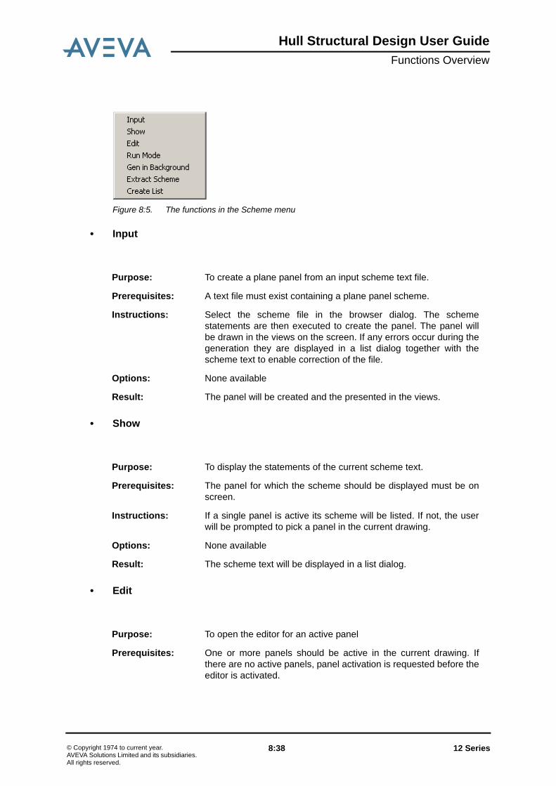
Hull Structural Design User GuideFunctions Overview
Figure 8:5. The functions in the Scheme menu
• Input
• Show
• Edit
Purpose: To create a plane panel from an input scheme text file.
Prerequisites: A text file must exist containing a plane panel scheme.
Instructions: Select the scheme file in the browser dialog. The schemestatements are then executed to create the panel. The panel willbe drawn in the views on the screen. If any errors occur during thegeneration they are displayed in a list dialog together with thescheme text to enable correction of the file.
Options: None available
Result: The panel will be created and the presented in the views.
Purpose: To display the statements of the current scheme text.
Prerequisites: The panel for which the scheme should be displayed must be onscreen.
Instructions: If a single panel is active its scheme will be listed. If not, the userwill be prompted to pick a panel in the current drawing.
Options: None available
Result: The scheme text will be displayed in a list dialog.
Purpose: To open the editor for an active panel
Prerequisites: One or more panels should be active in the current drawing. Ifthere are no active panels, panel activation is requested before theeditor is activated.
12 Series 8:38© Copyright 1974 to current year.AVEVA Solutions Limited and its subsidiaries. All rights reserved.

Hull Structural Design User GuideFunctions Overview
• Run Mode
• Gen in Background
Instructions: Once the editor is activated, the scheme of the first of the activepanel is presented and the full set of editor functions are availablevia an icon toolbar or by a right-click on the mouse.
Options: None available
Result: The scheme will be available for editing.
Purpose: This function gives the operator the possibility of controlling theexecution mode in a number of respects.
Prerequisites: None.
Instructions: Two different run mode controls can be updated:
1. ConfirmIn this subfunction, the operator selects whether a generatedcomponent should be displayed for acceptance before beinginserted in the picture (Confirm on) or if it is to be inserteddirectly (Confirm off). Default is Confirm off. When creating a BOUNDARY or a CURVE, the Confirm onstate has a special implication. Then the separate boundaries/curve segment will be available for inspection, one by one.This is intended as an aid in tracing errors when creating theouter geometry of the panel or a curve. The graphicalfunctions Zoom up, Zoom down and Original scale can beused to look into the corners, etc. in detail.
2. Trace If the keyword TRACEON is given in the Hull Modellingdefault file, and this function is set, valuable information forerror correction by AVEVA Marine will be written into the logfile. The activation of trace will have a heavy impact on theperformance!
Options: None available
Result: The run-mode of the system is changed.
Purpose: To generate panels in the background using the scheme files
Prerequisites: The scheme files must exists, preferable on the directory given bythe logical SB_SHIPSCH.
Instructions: Select one or many files in the presented file selection dialogue
12 Series 8:39© Copyright 1974 to current year.AVEVA Solutions Limited and its subsidiaries. All rights reserved.

Hull Structural Design User GuideFunctions Overview
• Extract Scheme
• Create List
Options: None available
Result: The panels will be generated in the background. Information aboutthe background job (log and list files) can be found in the LogViewer.
Purpose: To extract the schemes from existing panels and storing theseschemes on the directory given by the logical SB_SHIPSCH
Prerequisites: None
Instructions: Select one or many planar panels by picking in the drawing or byselecting from the data banks
Options: None available
Result: The schemes will be generated in the background. Informationabout the background job (log and list files) can be found in theLog Viewer
Purpose: This function is used to create lists of schemes. After defining thename of the scheme list file, scheme files are collected. The filetype is .schlst and the files are placed in the SB_SHIPSCHdirectory by default. A scheme can be part of many scheme lists.The scheme lists can be used by the Gen in Backgroundfunction.
Prerequisites: None
Instructions: Give a name of the scheme list file and select scheme files to beadded.
Options: None available
Result: The scheme list file will be created.
12 Series 8:40© Copyright 1974 to current year.AVEVA Solutions Limited and its subsidiaries. All rights reserved.

Hull Structural Design User GuideFunctions Overview
8.3.4 Editor
Figure 8:6. The functions in the Editor menu
• New
• Open
• Close
Purpose: To open the editor and a new scheme to create a panel using thescheme input language
Prerequisites: None
Instructions: Key in the name of the new panel. Continue by adding newstatements to the opened scheme
Options: None available.
Result: The editor is opened and ready for addition of new statements.
Purpose: To select an existing scheme file and to open this file in thestatement editor.
Prerequisites: None
Instructions: Select the scheme file to be open in the file selection dialogue.
Options: None available.
Result: The editor is opened and ready for addition of changes ofstatements.
Purpose: To close the currently available scheme in the editor withoutstoring any information
Prerequisites: None
Instructions: See purpose.
12 Series 8:41© Copyright 1974 to current year.AVEVA Solutions Limited and its subsidiaries. All rights reserved.

Hull Structural Design User GuideFunctions Overview
• Save
• Edit
• Statement
8.3.5 ViewThe functions within the View group are all functions covering the creation and manipulationof symbolic hull views. Below is given a description of each individual function within thisgroup.
Options: None available.
Result: The currently edited scheme is closed
Purpose: To store the currently edited scheme.
Prerequisites: None
Instructions: See purpose.
Options: None available.
Result: The currently edited scheme is stored as a file on the directoryassigned to the logical SB_SHIPSCH
Purpose: The Edit menu contains various edit functions (e.g. Cut, Past, Find,etc.) to simplify the editing of scheme files
Prerequisites: None
Instructions: Select appropriate sub-functions to simplify the editing work
Options: None available.
Result: The selected editing operations are performed.
Purpose: The Statement menu contains various functions on statements,e.g. to execute a statement, create a new statement, etc.
Prerequisites: None
Instructions: Select appropriate sub-function for the statement activity. Note thata new statement always must be created by using the sub-functionNew.
Options: None available.
Result: The selected statement operations are performed.
12 Series 8:42© Copyright 1974 to current year.AVEVA Solutions Limited and its subsidiaries. All rights reserved.

Hull Structural Design User GuideFunctions Overview
Figure 8:7. The View Menu
• Create
• Detail – Two Cursor Positions
Purpose: To add a new symbolic 2-D hull view to a drawing or redefine theview definition data of an existing view.
Prerequisites: A drawing must be open. To redefine view definition data, a 2-Dhull view must already exist.
Instructions: Enter the required view definition data in the fields of the form todefine view boundaries, plane and view direction. Panels, blocks,shell curves and shell profiles can also be included in or excludedfrom the view. Alternatively, the view may be created usingassembly names rather than panels and blocks.
Options: Options may be selected to allow utilisation of the current viewdefinition data of an existing view.
Result: If Add is selected, a view with the selected view definition data willbe created and transformations can be performed using Way toTransform before placing the view in the drawing. If Replace isselected, the newly created view will replace a picked existingview.
Purpose: To add a detail view of a specific section in a plane perpendicularto an existing view.
Prerequisites: A hull view must exist in the current drawing for extraction of detailviews.
Instructions: Select two cursor positions and specify a distance in front and adistance behind the plane of the existing view. As with Insert,specific panels, blocks, shell curves or shell profiles may chosen tobe included in or excluded from the view.
12 Series 8:43© Copyright 1974 to current year.AVEVA Solutions Limited and its subsidiaries. All rights reserved.

Hull Structural Design User GuideFunctions Overview
• Detail - Flange
• Detail - Stiffener
Options: Define the view direction and view depth by selecting Cancelwhen prompted to confirm the indicated line.
Result: A detail view will be created and transformations can be performedusing Way to Transform before placing the view in the drawing.
Purpose: To add a detail view of a flange from an existing view.
Prerequisites: A hull view containing a panel with a flange must exist in thecurrent drawing.
Instructions: Select a flange from an existing panel. If the flange is selectednear the midpoint, the detail view created will display the full size ofthe flange. If the flange is selected near an end, then the detailview will show only the chosen end of the flange. Detail viewscreated from curved flanges are not reliable.
Options: Options may be selected to allow the inclusion or exclusion ofspecific panels, blocks, shell curves and shell profiles in the detailview. If Options is not selected, only members of the indicatedpanel will be displayed in the detail view.
Result: A detail view will be created and transformations can be performedusing Way to Transform prior to placing the detail in the drawing.The view direction will be per the system default.
Purpose: To add a detail view of a stiffener from an existing view.
Prerequisites: A hull view containing a panel with a stiffener must exist in thecurrent drawing.
Instructions: Select a stiffener from an existing panel. If the stiffener is selectednear the midpoint, the detail view created will display the wholestiffener. If the stiffener is selected near an end, then the detail willshow only the chosen end of the stiffener. Detail views createdfrom curved stiffeners are not reliable.
Options: Options may be selected to allow the inclusion or exclusion ofspecific panels and blocks in the detail view. If Options is notselected, only members of the indicated panel will be displayed inthe detail view.
Result: A detail view will be created and transformations can be performedusing Way to Transform prior to placing the detail in the drawing.The view direction will be per the system default.
12 Series 8:44© Copyright 1974 to current year.AVEVA Solutions Limited and its subsidiaries. All rights reserved.
Hull Structural Design User GuideFunctions Overview
• Detail - Bracket
• Detail - Seam
• Recreate
Purpose: To add a detail view of a bracket from an existing view.
Prerequisites: A hull view containing a panel with a bracket must exist in thecurrent drawing.
Instructions: Select a bracket from an existing panel.
Options: Options may be selected to allow the inclusion or exclusion ofspecific panels, blocks, shell curves and shell profiles in the detailview. If Options is not selected, only members of the indicatedpanel and (in most cases) the item the bracket is connected to willbe displayed in the detail view.
Result: A detail view will be created and transformations can be performedusing Way to Transform prior to placing the detail in the drawing.The view direction will be per the system default.
Purpose: To add a large-scale detail section through a seam or a boundaryof a panel.
Prerequisites: A hull view containing a planar panel must exist in the drawing.
Instructions: Select a seam (or bevelled edge) from an existing panel.
Options: Not available.
Result: A detail view will be created and transformations can be performedusing Way to Transform prior to placing the detail in the drawing.The view direction will be per the system default.
Purpose: To update an existing view to include any modifications made tomodel objects in the range of the view.
Prerequisites: A hull view must exist in the current drawing.
Instructions: Select an existing view or choose All and confirm the selection.
12 Series 8:45© Copyright 1974 to current year.AVEVA Solutions Limited and its subsidiaries. All rights reserved.

Hull Structural Design User GuideFunctions Overview
• Modify - Remake Panel
• Modify - Add Reflected Image
Options: 3 options are available:• To merge the indicated view with a previously stored view.• To suppress the addition of the new panels.• To recreate the view with mould line representation.
Note: Any added or changed panels to such a view will bepresented with thickness. If this occurs, a new recreate ofthe view must be executed.
Result: If one hull view is selected to update, that view will be regeneratedincluding any model changes made to panels shown in the view. IfAll is selected, then all views in the drawing will be regenerated.Note that the previous definition data of the view are chosen by thesystem when regenerating the view. Any modifications made to theview outside the current limits will be lost unless the limits of theview are modified.
Purpose: To replace a single updated panel in a view.
Prerequisites: A hull view must exist in the current drawing.
Instructions: Select the required panel in an existing view and confirm whenprompted.
Options: Options may be selected to switch the drawing mode from Planeview to Intersection and vice-versa.
Result: The selected panel is regenerated in the chosen hull view.
Purpose: To add the reflected image of an existing panel.
Prerequisites: A hull view showing a symmetric panel must exist in the currentdrawing.
Instructions: Select the panel in an existing view and confirm when prompted.
Options: Options may be selected to switch the drawing mode from Planeview to Intersection and vice-versa.
Result: The image of the selected panel, mirrored in the CL plane isdisplayed in the chosen view.
Note: that if any area of the mirrored image falls outside theexisting limits of the view, that area will be lost when theview is regenerated.
12 Series 8:46© Copyright 1974 to current year.AVEVA Solutions Limited and its subsidiaries. All rights reserved.

Hull Structural Design User GuideFunctions Overview
• Modify - Add Named Panel
• Modify - Modify Limits
• Select
Purpose: To display an additional, user-defined panel in an existing view.
Prerequisites: A hull view must exist in the current drawing.
Instructions: Indicate the existing view in which the new panel should bedisplayed, then enter the panel name.
Options: None available.
Result: The specified panel is displayed in the chosen view.
Note: that if any area of it falls outside the existing limits of theview, that area will be lost when the view is regenerated.
Purpose: To redefine the limits of an existing view.
Prerequisites: A hull view must exist in the current drawing.
Instructions: Indicate and confirm the view to be modified. Select cursorpositions for the diagonally opposite corners of a box indicating thedesired limits of the view.
Options: Select Options to modify the depth of the view, in front of andbehind the existing plane.
Result: The view limits will be changed in the drawing and the view will beautomatically regenerated to fit the new limits.
Purpose: To select/deselect views to be updated when creating panelcomponents.
Prerequisites: A drawing with more than one view must be current.
Instructions: Indicate the view to change the status on.
Options: Options may be selected to switch between select and deselect.
Result: Views marked with a rectangle will be updated with generatedcomponents. Views marked with a cross will NOT be updated.
12 Series 8:47© Copyright 1974 to current year.AVEVA Solutions Limited and its subsidiaries. All rights reserved.

Hull Structural Design User GuideFunctions Overview
• Edit
• Properties
8.3.6 PosNo
8.3.7 SelectThe functions within the Select group are all functions covering the selection and handling ofactive planar panels. Below is given a description of each individual function within thisgroup.
Purpose: To edit (move) automatically created text and symbols in asymbolic hull view. Changes made with this function will beretained also when the view is recreated.
Prerequisites: A drawing with a symbolic hull view must exist.
Instructions: Indicate the information to move and perform the transformation.
Options: None available
Result: The changes are performed and marked to be unaffected by anyrecreate view operations.
Purpose: To allow the user to blank (or un-blank) the symbolic or textualinformation on an individual panel or on a complete hull view.
Prerequisites: A drawing with a symbolic hull view must exist.
The hull defaults values control the initial status of the blank/un-blank information when a view is created.
Instructions: A dialogue with display options are used to set which informationshould be displayed or hidden.
Options: None available.
Result: If a view is selected, previously selected display options onindividual models are overruled. If a single model is selected, thevalues previously set on a belonging view are overridden.
Purpose: To handle position numbering on planar panel parts
Instructions: Detailed instructions can be found in Hull->Planar Modelling /Interactive Planar Hull Modelling Functions / PosNo.
12 Series 8:48© Copyright 1974 to current year.AVEVA Solutions Limited and its subsidiaries. All rights reserved.

Hull Structural Design User GuideFunctions Overview
Figure 8:8. The Planar Select Menu
• Activate
• Store
Purpose: To activate one or more panels, allowing changes to be made tothe panels without opening the scheme. The activated panels willbe locked in the database to prevent others from making changes.
Prerequisites: A hull view containing the required panels must exist in the currentdrawing.
Instructions: Indicate the panel to be activated. Continue indicating if furtherpanels should be activated.
Options: Selecting Options will display a form, which gives the option ofincluding and excluding specific panels or blocks, given as nameswith wild cards. Panel activation may be performed by acombination of both graphically selected and named panels.
Result: The selected panels will be highlighted with a rectangle placedaround all views in the drawing that contain the panel. Therectangle will have either a letter S or a letter M on the line. Smeans Stored and indicates that the panel is identical to the panelon the data bank, and M means Modified and indicates that thepanel has been modified after activation.
Purpose: To store active panels that have been changed.
Prerequisites: One or more panels must be active in hull views in the currentdrawing. One or more active panels must have been changed.
Instructions: Choose Save from the menu. Confirmation to save panels is onlyrequested if a panel has been modified. Confirmation will not berequired if All is selected.
Options: None available.
Result: Panels confirmed for saving will be updated on the data bank, andthe schemes will be re-written to include the modificationsprovided storing of schemes is active. The M which appeared onthe top line of the highlight rectangle to indicate modification, willrevert to an S when the panel is saved.
12 Series 8:49© Copyright 1974 to current year.AVEVA Solutions Limited and its subsidiaries. All rights reserved.

Hull Structural Design User GuideFunctions Overview
• Skip
• Store and Skip
• List Activated
8.4 Functions in the Curved MenuBelow follows a short description of the functions used to create and view the curved partsof the ship, e.g. shell structure such as seams, shell plates and shell longitudinals. Detaileddescription can be found in Hull / Curved Modelling.
The corresponding pull-down menus are shown below.
Purpose: To deactivate previously selected panels without storing.
Prerequisites: One or more panels must be active in hull views on the currentdrawing.
Instructions: Choose Deselect from the menu. Confirmation to Deselect panelsis only requested if a panel has been modified. Modifications willnot be saved if panel deselection is confirmed. Confirmation willnot be required if All is selected.
Options: None available.
Result: All previously selected panels will be deactivated. If a panel hasbeen changed while activated, it will be removed from the workarea and the picture. The highlight rectangle around the selectedpanels will disappear.
Purpose: To first store and then deactivate previously selected panels.
Prerequisites: See the two functions Store and Skip.
Instructions: See the two functions Store and Skip.
Options: None available.
Result: See the two functions Store and Skip.
Purpose: To list all selected objects.
Prerequisites: None.
Instructions: Not applicable.
Options: None available.
Result: The selected objects are listed.
12 Series 8:50© Copyright 1974 to current year.AVEVA Solutions Limited and its subsidiaries. All rights reserved.

Hull Structural Design User GuideFunctions Overview
Figure 8:9. The Curved Model Menu.
8.4.1 ModelThis menu contains the functions used to create objects in the curved part.
Figure 8:10. The Model Menu
• Create Seam/Butt
Purpose: To create or modify a seam or butt in a hull surface.
Prerequisites: None.
Instructions: • In create mode, the user must give a curve definition, a seamnumber and symmetry information. If a curve is alreadyselected, it will be used as the curve definition. If severalcurves are selected, the seams may be automatically named.In this case, the user must enter the first seam name.The seam may also be marked as a block limit seam, whichwill be drawn differently than other seams in some views. Theseam may be symmetric (if the curve is defined on portside),port side specific (again, curve defined on portside), starboardspecific (if the curve is defined on starboard) or over thecentreline (if the curve extends over the centreline).
12 Series 8:51© Copyright 1974 to current year.AVEVA Solutions Limited and its subsidiaries. All rights reserved.

Hull Structural Design User GuideFunctions Overview
• Create Shell Plate
• In modify mode, the user may change any part of the seam,including its name and box. The Modify Curve button lets theuser change the curve definition. Since the seam is trimmedwith the box, the extension of the seam can be changed bymodifying the box co-ordinates.
Options: None available.
Result: • In create mode, a new seam will be created and selected. TheStore function may be used to store the seam on the hull formdata bank.
• In modify mode, the selected seam will be updated with thenew definition data. To make the changes permanent, Storemust be used. Using the Skip function before the seam hasbeen stored will undo the changes.
Purpose: To create one or several shell plates.
Prerequisites: The seams and butts defining the shell plate or shell plates mustexist.
Instructions: This function may be used either to create a single shell plate, orseveral plates generated by a grid of intersecting seams and butts.If a temporary plate has been created via the Developed Platefunction in the View menu and this is still selected, this one will beused as input to this function, and the user will not be prompted topick any seams and butts.
If no plate is selected, in the single plate case, the user isprompted to indicate which seams and butts that define the plate.These must be indicated in a clock-wise direction when seen fromthe inside of the ship, and the first seam or butt must be the oneclosest to the aft end of the ship. The plate may consist of three,four or five edges. If the plate has less than five edges, the usermust end the picking of seams and butts by Operation Complete.
In case the user wants to create several plates from a seam/buttgrid, he will first be prompted to indicate butts from the aft end indirection forward. When the picking of butts has been finished withOperation Complete, the user will be asked to indicate seamsfrom the top in the side shell in direction towards the centre line.
When all seams and butts have been picked, the plate data formwill appear. This form is used to enter all main plate data such assymmetry information, position number, thickness, material quality,bevelling and excess. If several plates are created at once, AutoNumbering may be checked to automatically set the positionnumber of all plates. Only the position number of the first plate isthen entered, and this number will be increased by one for eachnew plate. If All is checked, the entered plate data will be valid forall plates created. Otherwise, the user must fill in the form once forevery plate.
12 Series 8:52© Copyright 1974 to current year.AVEVA Solutions Limited and its subsidiaries. All rights reserved.

Hull Structural Design User GuideFunctions Overview
• Shell Profile - Create
Finally, the plate name form must be filled in to give the platenames. If Add Posno is checked, the position number of a platewill be added at the end of the name given in the Plate Name field.The Auto Name check box is used to automatically form platenames the same way as for hull curves and storable planes.Checking Templates will make plate templates be generated forthe plate. These templates are stored together with the plate itself.
Options: Activating “Options” displays a menu that allows the designer tocontrol the development process in a number of ways:
• If roll axis should be evaluated or not• Method. Options are contraction (plates to be formed by
shrinkage (heating/cooling))• The raw plate margin• The direction of strips used in the plate development• The number of strips• The tolerance of the spline function used when creating the
edges of the developed plate.
Remark:
In addition to these options there is an additional option to controlthe plate development. Normally the strips are restricted by curvesin principal planes. The environment variableSBH_PERP_STRIPS can modify that. If set to DIS the strip curveswill be distributed along the longer edge of the plate in the sameproportion girth-wise as along the base line of the plate.If set toany other value the strip curves will be perpendicular to thebaseline curve.
Result: One or more new shell plates will be created and selected. TheStore function may be used to store the plates on the plate databank.
Purpose: To create a longitudinal or transversal
Prerequisites: None.
Instructions: • In create mode, the user must give a curve definition and shellprofile data, which includes symmetry information, profile typeand dimensions, material orientation, etc. If a curve is alreadyselected, it will be used as the trace curve. If several curvesare selected, the shell profiles may be automatically named.In this case, the user must enter the first profile number, whichwill then be increased by 10 for longitudinals and 1 fortransversals.
12 Series 8:53© Copyright 1974 to current year.AVEVA Solutions Limited and its subsidiaries. All rights reserved.

Hull Structural Design User GuideFunctions Overview
• Shell Profile – Split Symmetric
• Shell Stiffener - Split
The profile may be symmetric (if the curve is defined onportside), port side specific (again, curve defined on portside),starboard specific (if the curve is defined on starboard) or overthe centreline (if the curve extends over the centreline).Profile type and dimensions can be entered in the form orselected from lists. The profile data can also copied fromanother shell profile (Same As).
• In modify mode, the user may change any part of the shellprofile, including its name and box. The Modify Curve buttonlets the user change the curve definition, and the Modify Boxbutton is used for changing the shell profile box. Since theshell profile is trimmed with the box, the extension of theprofile can be changed by modifying the box coordinates. Ifseveral shell profiles are selected, All may be checked tomake the same changes to all of them. The Same Box ForAll check box may be used to set the same box for allselected shell profiles.
Options: Use the Option button for advanced selection methods.
Result: • In create mode, a new shell profile will be created andselected. A single shell stiffener will also be created extendingalong the whole profile. The Store function may be used tostore the shell profile and the shell stiffener on the hullstructure data bank.
• In modify mode, the shell profile will be updated with the newdefinition data. To make the changes permanent, Store mustbe used. Using the Skip function before the shell profile hasbeen stored will undo the changes.
Purpose: To split a symmetric shell profile into port and starboard specificobjects
Prerequisites: None.
Instructions: When splitting a symmetrical shell profile, the user is asked toselect a symmetrical shell profile to be split into a port and astarboard specific instance
Options: None available.
Result: When performing a splitting, two new shell profiles will be created,one valid portside and the other on starboard.
Purpose: To split an existing shell stiffener into two or more smaller pieces.
Prerequisites: None.
12 Series 8:54© Copyright 1974 to current year.AVEVA Solutions Limited and its subsidiaries. All rights reserved.

Hull Structural Design User GuideFunctions Overview
• Shell Stiffener - Combine
• Shell Stiffener - To Profile DB
Instructions: A pop-up menu will let the user select the kind of object that shouldbe used to split the stiffeners. Objects that can be used to split ashell stiffener are:
• Hull curves• Seams• Shell profiles• Planes• Planar panels.
If any shell stiffeners are already selected, these will be split, and ifany shell profiles are selected, the shell stiffeners belonging tothese will be selected. As the final step, the user has to indicatethe objects to use for the splitting. Several shell stiffeners may beselected at a time, as well as several splitting objects.
Options: None available.
Result: The selected shell stiffeners will be split in the intersections withthe selected splitting objects. The Store function may be used tostore the shell stiffeners and their shell profiles on the hull structuredata bank.
Purpose: To combine previously split shell stiffeners.
Prerequisites: Two or more shell stiffeners that can be combined must exist. Twoshell stiffeners may be combined only if they are adjacent to eachother and belong to the same curve branch of a shell profile.
Instructions: If no shell stiffeners are selected, the user will be prompted toindicate which stiffeners to combine. After this is finished withOperation Complete, or if some stiffeners were already selected,the stiffeners will be combined.
Options: None available.
Result: The selected shell stiffeners will be combined into the smallestpossible number of stiffeners. The Store function may be used tostore the shell stiffeners and their shell profiles on the hull structuredata bank.
Purpose: To transfer shell stiffeners ready for production to the profile databank.
Prerequisites: The shell stiffener or shell stiffeners to transfer must exist.
12 Series 8:55© Copyright 1974 to current year.AVEVA Solutions Limited and its subsidiaries. All rights reserved.
Hull Structural Design User GuideFunctions Overview
• Create Feature - Hole
Instructions: Any selected shell stiffeners or shell stiffeners belonging to anyselected shell profiles will be used as input to this function. In casenothing is selected, the user will be prompted to pick the desiredshell stiffeners, and end the input with Operation Complete.When some stiffeners have been selected, they will be written tothe profile data bank.
Options: None available.
Result: The stiffeners will be output to the profile data bank.
Remark:
The release of shell stiffeners is normally done via the Cpanpartsfunction in the Hull Production Interface.
Purpose: To create one or more holes in a number of shell profiles.
Prerequisites: A shell profile (and thus at least one shell stiffener) must exist. Theenvironment variable SBH_HOLE_CTRL must be set.
Instructions: • In create mode, the user must indicate one or more shellprofiles in which to create the holes, and then give a holedefinition. If any shell profiles are already selected, they willbe used as input to this function.The user must enter the position of the hole or holes in thePositions field. The hole type may be entered in the form,selected from a list or copied from another hole (Same As).Alternatively, the hole may be generated from an arbitrarytwo-dimensional curve object (Arbitrary). A distance from theshell profile trace to the centre of the hole may be set, as wellas the inclination angle of the hole.
• In modify mode, the user may change the hole definition. Themodification will only affect the holes in the selected shellprofile. If holes have been created in several profiles at once,the hole definitions in the different profiles must be changedone at a time.
Options: None available.
Result: • In create mode, holes will be created in the selected shellprofiles. The Store function may be used to store the shellprofile with the new holes on the hull structure data bank.
• In modify mode, the shell profile will be updated with the newhole definition. To make changes permanent, Store must beused. Using the Skip function before the shell profile hasbeen stored will undo the changes.
12 Series 8:56© Copyright 1974 to current year.AVEVA Solutions Limited and its subsidiaries. All rights reserved.

Hull Structural Design User GuideFunctions Overview
• Create Feature - Notch
• Create Feature - Cutout
Purpose: To create one or more notches in a number of shell profiles.
Prerequisites: A shell profile (and thus at least one shell stiffener) must exist. Theenvironment variable SBH_NOTCH_CTRL must be set.
Instructions: • In create mode, the user must indicate one or more shellprofiles in which to create the notches, and then give a notchdefinition. If any shell profiles are already selected, they willbe used as input to this function.The user may enter notch positions or names of the seams atwhich to set notches in the Positions field. Multiple seamnames are separated by a comma. Reference is used to tellwhether coordinates or seam references have been entered.If Indicate Seam Refs is checked, the user will instead beprompted to pick seams interactively after the form has beenclosed with the Ok button. The notch type may be entered inthe form, selected from a list or copied from another notch(Same As). Alternatively, the notch may be generated froman arbitrary two-dimensional curve object (Arbitrary).
• In modify mode, the user may change the notch definition.The modification will only affect the notches in the selectedshell profile. If notches have been created in several profilesat once, the notch definitions in the different profiles must bechanged one at a time.
Options: None available.
Result: • In create mode, notches will be created in the selected shellprofiles. The Store function may be used to store the shellprofile with the new notches on the hull structure data bank.
• In modify mode, the shell profile will be updated with the newnotch definition. To make changes permanent, Store must beused. Using the Skip function before the shell profile hasbeen stored will undo the changes.
Purpose: To create one or more cutouts in a number of shell profiles.
Prerequisites: A shell profile (and thus at least one shell stiffener) must exist.
12 Series 8:57© Copyright 1974 to current year.AVEVA Solutions Limited and its subsidiaries. All rights reserved.

Hull Structural Design User GuideFunctions Overview
• Create Feature - Marking
Instructions: • In create mode, the user must indicate one or more shellprofiles in which to create the cutouts, and then give a cutoutdefinition. If any shell profiles are already selected, they willbe used as input to this function.The user may enter names of the penetrating shell profiles inthe Positions field. Multiple profile names are separated by acomma. If Indicate Shell Profiles is checked, the user willinstead be prompted to pick shell profiles interactively afterthe form has been closed via the Ok button. The cutout typemust also be entered in the Cutout Type field.
• In modify mode (Modify was selected in the Model menu),the user may change the cutout definition. The modificationwill only affect the cutouts in the selected shell profile. Ifcutouts have been created in several profiles at once, thecutout definitions in the different profiles must be changedone at a time.
Options: None available.
Result: • In create mode, cutouts will be created in the selected shellprofiles. The Store function may be used to store the shellprofile with the new cutouts on the hull structure data bank.
• In modify mode, the shell profile will be updated with the newcutout definition. To make changes permanent, Store must beused. Using the Skip function before the shell profile hasbeen stored will undo the changes.
Purpose: To create one or more markings in a number of shell profiles.
Prerequisites: A shell profile (and thus at least one shell stiffener) must exist.
Instructions: • In create mode, the user must indicate one or more shellprofiles in which to create the markings, and then give amarking definition. If any shell profiles are already selected,they will be used as input to this function.The user must enter the position of the marking or markings inthe Positions field. The Profile Height and Symmetriccheck boxes together with Direction and Inclination Anglemay be used to set the appearance of the markings. A textmay also be entered in the Marking Text field.
• In modify mode, the user may change the marking definition.The modification will only affect the markings in the selectedshell profile. If markings have been created in several profilesat once, the marking definitions in the different profiles mustbe changed one at a time.
12 Series 8:58© Copyright 1974 to current year.AVEVA Solutions Limited and its subsidiaries. All rights reserved.

Hull Structural Design User GuideFunctions Overview
• Create Curved Panel
Options: None available.
Result: • In create mode, markings will be created in the selected shellprofiles. The Store function may be used to store the shellprofile with the new markings on the hull structure data bank.
• In modify mode, the shell profile will be updated with the newmarking definition. To make changes permanent, Store mustbe used. Using the Skip function before the shell profile hasbeen stored will undo the changes.
Purpose: To create or modify a curved panel.
Prerequisites: Shell plates and shell stiffeners to be included in the panel mustexist.
Instructions: • In create mode, the user must first enter the panel and blocknames and specify the symmetry. The block may also beselected from a list by pressing the Select button. Note thatthe panel symmetry must correspond to the symmetry of theplates and stiffeners to be included in the panel. This meansthat portside or starboard specific panels, as well assymmetric panels, may only consist of shell plates and shellstiffeners with the same symmetry as the curved panel. In apanel extending over the centre line, there are no limitationswith regard to plate and stiffener symmetries.The next step is to select what parts to include in the curvedpanel. The user is first prompted to indicate (in any order) allshell plates to include and then (after Operation Complete)all shell stiffeners. After that, the curved panel will be created.
• In modify mode, the user may change symmetry information,block name and panel name. It is also possible to add orremove shell plates and shell stiffeners by using one of thePlates or Stiffeners buttons. The Handle Holes buttonmakes it possible to add holes in the curved panel orremoving existing holes.
Options: None available.
Result: • In create mode, a new curved panel will be created andselected. The Store function may be used to store the panelon the hull structure data bank.
• In modify mode, the curved panel will be updated with thenew definition data. To make the changes permanent, Storemust be used. Using the Skip function before the panel hasbeen stored will undo the changes.
12 Series 8:59© Copyright 1974 to current year.AVEVA Solutions Limited and its subsidiaries. All rights reserved.

Hull Structural Design User GuideFunctions Overview
• Create Hull Curve
• Create Storable Plane
Purpose: To create or modify a hull curve in a hull surface.
Prerequisites: None.
Instructions: • In create mode, the user must give a curve definition and ahull curve name. If a curve is already selected, it will be usedas the curve definition. If several curves are selected, the hullcurves may be automatically named. In this case, the usermay enter the name of the first hull curve, with the numericalpart to increase for every following curve surrounded by <and > symbols. If < and > are not a part of the name, arunning number starting at one will be added at the end of theentered name. Alternatively, the name may include arepetition term within < and >, where the repetition term willgenerate the names of the curves. Examples of valid entriesin the name field are HCURVE, HCURVE<5>C andHCURVE<5(10)25>C (with the last example valid only withthree selected curves).
• In modify mode, the user may change any part of the hullcurve, including its name and box. The Modify Curve buttonlets the user change the curve definition. Since the hull curveis trimmed with the box, the extension of the hull curve can bechanged by modifying the box coordinates.
Options: None available.
Result: • In create mode, a new hull curve will be created and selected.The Store function may be used to store the hull curve on thehull form data bank.
• In modify mode, the hull curve will be updated with the newdefinition data. To make the changes permanent, Store mustbe used. Using the Skip function before the hull curve hasbeen stored will undo the changes.
Purpose: To create or modify a storable plane.
Prerequisites: None.
Instructions: • In create mode, the user must give a plane definition and aplane name. If a temporary plane (created with one of thePlane functions in the Geometry menu) is already selected, itwill be used as the plane definition. If several planes areselected, the storable planes may be automatically named.The rules for auto naming of storable planes are the same asfor hull curves.
• In modify mode, the user may change any part of the plane,including its name. The Modify Plane button lets the userchange the plane definition.
12 Series 8:60© Copyright 1974 to current year.AVEVA Solutions Limited and its subsidiaries. All rights reserved.
Hull Structural Design User GuideFunctions Overview
• Create Storable Point
• Create Curved Surface
Options: None available.
Result: • In create mode, a new storable plane will be created andselected. The Store function may be used to store the planeon the hull form data bank.
• In modify mode, the plane will be updated with the newdefinition data. To make the changes permanent, Store mustbe used. Using the Skip function before the plane has beenstored will undo the changes.
Purpose: To create or modify a storable point.
Prerequisites: None.
Instructions: • In create mode, this function lets you name and store a pointfor later use. The storable point object is simply a temporarypoint with a user-defined name. If any points are selectedwhen the function is invoked, these are used. Otherwise, youwill be prompted for a point definition. Next, a form will bedisplayed allowing the designer to name the point with apossibility of auto-naming. Using auto-naming, the Name fieldthen contains the name of the first point. This name musthave a numerical part surrounded by the characters < and> to define what to increment. If this is not the case, an ordinalnumber will be added at the end of the name as given in theName field, starting with 1 for the first point. For examples,please refer to the description of the Create Hull Curve.
• In modify mode, the user may change any part of the plane,including its name. The Modify Point button lets the userchange the point definition.
Options: None available.
Result: • In create mode, a new storable point will be created andselected. The Store function may be used to store the pointon the hull form data bank.
• In modify mode, the plane will be updated with the newdefinition data. To make the changes permanent, Store mustbe used. Using the Skip function before the plane has beenstored will undo the changes.
Purpose: To create or modify a parametric curved surface
Prerequisites:. The TID Surface system must be in use.
12 Series 8:61© Copyright 1974 to current year.AVEVA Solutions Limited and its subsidiaries. All rights reserved.

Hull Structural Design User GuideFunctions Overview
• Delete
• Recreate
Instructions: A dialogue for creation or modification of three types of parametricsurfaces is presented. The three types, Cylinder, Cone and Fillet ,are presented on different flaps within the dialogue.
The dialogue expects definition data to be keyed in or picked fromexisting information on the drawing canvas.
Options: None available.
Result: The created surface is presented on the canvas, registered in thesystem and is ready to be used for any curved hull operation.Boundary curves are created and can be used directly for seamgeneration.
Purpose: To delete model objects (seams, hull curves, storable planes, shellplates, curved panels, shell profiles and parametric surfaces) fromtheir respective data banks or delete features from shell profiles.
Prerequisites: None.
Instructions: Any objects or features already selected will be used as input tothis function. If no objects or features are selected, the user will beprompted to indicate one or more objects to delete. If any featureshave been deleted, their respective shell profiles will automaticallybe selected afterwards. These profiles must be stored for theremoval of the features to take effect.
Options: Using Options will bring up the Advanced selection dialog box.
Result: The selected objects or features will be deleted.
Purpose: To regenerate model objects from their definition data.
Prerequisites: None.
Instructions: Any model objects already selected will be used as input to thisfunction. If no model objects are selected, the user will beprompted to indicate one or more objects to recreate. Afterrecreation, all objects must be stored on the data bank. Using theSkip function without first storing an object will undo the recreationof that object.
Options: Using Options will bring up the Advanced selection dialog box.
Result: The selected model objects will be recreated from their definitiondata.
12 Series 8:62© Copyright 1974 to current year.AVEVA Solutions Limited and its subsidiaries. All rights reserved.

Hull Structural Design User GuideFunctions Overview
• Modify
• Topology
8.4.2 The Geometry MenuThe functions in this menu are used to create geometry, such as points, planes and curves,which can be used to define model objects.
Purpose: To modify the definition of model and geometry objects andfeatures.
Prerequisites: None.
Instructions: Any objects or features already selected will be used as input tothis function. If no objects or features are selected, the user will beprompted to indicate an object or feature to modify.
When objects have been selected the modification procedure issimilar to the creation of the respective object.
Options: Using Options will bring up the Advanced selection dialog box.
Result: The modification is made.
Purpose: This function can be used to visualize the dependencies betweenmodel objects using the topology information using curved objectas a basis. Given a model object both the objects defining it andthe objects depending on it can be shown.
Furthermore the objects shown can be listed and activated (onlycurved objects). Once the activation is made, they can be e.g.regenerated to adapt to any changes in the defining objects usingthe Recreate function described above.
Prerequisites: None available.
Instructions: Multiple objects can be given initially and the resulting objects canbe used for a new search. This means that the dependencies canbe visualized repeatedly, level-by-level. To benefit from thisfunction the model must be created using topological referencesrather than pure coordinates whenever possible.
Options: Using Options will bring up the Advanced selection dialog box.
Result: The activation of panels can be made using the stored topologyinformation of AVEVA Marine
12 Series 8:63© Copyright 1974 to current year.AVEVA Solutions Limited and its subsidiaries. All rights reserved.

Hull Structural Design User GuideFunctions Overview
Figure 8:11. The Geometry Menu.
• Point - 3 Coords
• Point - On Surface
Purpose: To create or modify a point defined by three coordinates.
Prerequisites: None.
Instructions: • In create mode, the x, y and z coordinates of the point mustbe entered. After the user has pressed the Ok button, thepoint will be created. Apply has the same function as the Okbutton, but keeps the form open for input of another point.
• In modify mode, the point definition may be changed. SelectType will let the user change the point into another type (pointon the surface or point in the intersection between a curveand a plane).
Options: Options may be used for further possibilities to define the point.
Result: • In create mode, a new point at the given location will becreated and selected.
• In modify mode, the selected point will be updated with thenew definition data.
Purpose: To create or modify a point on the default surface.
Prerequisites: None.
Instructions: • In create mode, two of the point coordinates must be entered.Optionally, the third one may be entered as an approximatecoordinate. In case of ambiguities, the system will use thiscoordinate to determine the location in the surface. The exactvalue of the third coordinate will be automatically calculatedwhen the user pressed the Ok button. Apply has the samefunction as the Ok button, but keeps the form open for input ofanother point.
• In modify mode, the point definition may be changed. SelectType lets the user change the point into another type (threecoordinates or point in the intersection between a curve and aplane). Select Surface lets the user select another surface touse in the point definition.
12 Series 8:64© Copyright 1974 to current year.AVEVA Solutions Limited and its subsidiaries. All rights reserved.

Hull Structural Design User GuideFunctions Overview
• Point - Curve + Plane/Plane Panel
• Plane - Principal
Options: None available.
Result: • In create mode, a new point at the given location will becreated and selected.
• In modify mode, the selected point will be updated with thenew definition data.
Purpose: To create or modify a point in the intersection between a curve(shell curve, seam or hull curve) and a plane.
Prerequisites: None.
Instructions: • In create mode, the user is asked to define a curve and aplane. Any curves or planes already selected will be used asinput to this function
• In modify mode, the point definition may be changed. SelectType lets the user change the point into another type (threecoordinates or point on the surface).
Options: None available.
Result: • In create mode, a new point at the given location will becreated and selected. If several curves or planes areselected, points will be created in all intersections.
• In modify mode, the selected point will be updated with thenew definition data.
Purpose: To create or modify a plane perpendicular to one of the principalaxes.
Prerequisites: None.
Instructions: • In create mode, the location of the principal plane must beentered. When Ok is pressed, the plane will be created.Apply has the same function as the Ok button, but keeps theform open for input of another plane.
• In modify mode, the plane definition may be changed. SelectType lets the user change the plane into another type (threepoints, 2 points and axis or 2 points and angle).
Options: None available.
Result: • In create mode, a new plane at the given location will becreated and selected.
• In modify mode, the selected plane will be updated with thenew definition data.
12 Series 8:65© Copyright 1974 to current year.AVEVA Solutions Limited and its subsidiaries. All rights reserved.
Hull Structural Design User GuideFunctions Overview
• Plane - 3 Points
• Plane - 2 Points + Axis
Purpose: To create or modify a plane defined by three points.
Prerequisites: None.
Instructions: • In create mode, the user will be prompted to define threepoints. Any points already selected will be used as input tothis function. When three points have been given, a planerunning through these points will be created.
• In modify mode, the plane definition may be changed. SelectType lets the user change the plane into another type(principal plane, 2 points and axis or 2 points and angle).
Options: None available.
Result: • In create mode, a new plane at the given location will becreated and selected.
• In modify mode, the selected plane will be updated with thenew definition data.
Purpose: To create or modify a plane defined by two points and a principalaxis.
Prerequisites: None.
Instructions: • In create mode, the user will be prompted to define twopoints. Any points already selected will be used as input tothis function. The user must also select the principal axis touse in the definition of the plane. The line between the twopoints and the line made up by the selected principal axisdefine the plane.
• In modify mode, the plane definition may be changed. SelectType lets the user change the plane into another type(principal plane, 3 points or 2 points and angle).
Options: None available.
Result: • In create mode, a new plane at the given location will becreated and selected.
• In modify mode, the selected plane will be updated with thenew definition data.
12 Series 8:66© Copyright 1974 to current year.AVEVA Solutions Limited and its subsidiaries. All rights reserved.

Hull Structural Design User GuideFunctions Overview
• Plane - 2 Points + Angle
• Plane - Rotated
Purpose: To create or modify a plane defined by two points and an angleagainst one of the principal axes.
Prerequisites: None.
Instructions: • In create mode, the user will be prompted to define twopoints. Any points already selected will be used as input tothis function.The user must also enter an angle against one of the principalaxes. This angle will also be used in the definition of theplane.An angle of 0 always means the positive direction of thespecified axis.A positive angle means rotation towards the positive directionof the next higher ordered axis (a rotation from the z-axis isalways made towards the x-axis). E.g. if the axis is x and theangle 45 degrees, this will result in a line a bisector of the x-and y- axes. The line between the two points and the linemade up from rotating the selected axis the desired angledefine the plane.Optionally, a second axis and angle may be entered. Theseare not used in the plane definition, but if a shell profile iscreated, by intersecting the plane with a surface, theinclination angles will automatically be copied from the planedefinition.
• In modify mode, the plane definition may be changed. SelectType lets the user change the plane into another type(principal plane, 3 points or 2 points and axis).
Options: None available.
Result: • In create mode, a new plane at the given location will becreated and selected.
• In modify mode, the selected plane will be updated with thenew definition data.
Purpose: This function creates a plane by rotating a principal plane aroundone of the principal axis.
Any principal plane already selected will be used as a base object,which means that rotated planes can be created from several baseplanes in a single operation. If there are no principal planesselected, you will be asked to define or select one or more.
Prerequisites: None.
12 Series 8:67© Copyright 1974 to current year.AVEVA Solutions Limited and its subsidiaries. All rights reserved.

Hull Structural Design User GuideFunctions Overview
• Plane - Reflected
• General Cylinder
Instructions: When the base planes have been defined, then a dialogue ispresented. Within the dialogue, the rotational axis, the angle axis,coordinates along the chosen rotational axis, used for defining theline around which the plane will be rotated and angles defining theangle between the angle axis and the resulting plane. Severalcoordinates and angles may be specified at once with a repetitionterm, e-g- for angles in the form <first angle><spacing><lastangle>.
Options: None available.
Result: Planes will be created according to input.
Purpose: This function creates a plane by reflecting another one in thecentre line of the ship.
Prerequisites: None.
Instructions: Any planes already selected will be used as input to this function. Ifthere are no planes selected, you will be asked to define or selectone or more.
If the function is used in modify mode, the user is also given thepossibility to modify the base plane and the type of plane
Options: None available.
Result: Planes will be created according to input.
Purpose: To create or modify a general cylinder.
Prerequisites: If points in the cylinder directrix are to be indicated in a view, aplane view perpendicular to the generator axis of the generalcylinder must exist.
Instructions: • In create mode, the user must first select the generator axis ofthe general cylinder. When this has been done, any numberof points forming the directrix may be entered. The points mayeither be given as coordinates in a form or (using the Indicatebutton) indicated in the drawing. The Apply button should beused to enter all points but the last one, in which case the Okbutton is used. This will close the form, and a second form,letting the user set the limits and end point angles of thecylinder, will appear.
• In modify mode, the cylinder definition may be changed.
12 Series 8:68© Copyright 1974 to current year.AVEVA Solutions Limited and its subsidiaries. All rights reserved.

Hull Structural Design User GuideFunctions Overview
• Shell Curve - By Plane
• Shell Curve - By General Cylinder
Options: In create mode, the user may use Options when indicating pointsin the drawing to get back to the form for entering points.
Result: • In create mode, a new general cylinder will be created andselected.
• In modify mode, the selected general cylinder will be updatedwith the new definition data.
Purpose: To create or modify a shell curve in the intersection between aplane and the default surface.
Prerequisites: None.
Instructions: • In create mode, the user will be prompted to define a plane.Any plane already selected will be used as input to thisfunction. This plane will then be cut with the default surface,and the resulting curve will be added to the selection.
• In modify mode, the curve definition may be changed. SelectType lets the user change the curve into another type(intersection between surface and general cylinder, parallelcurve or combined curve). By use of the button Modify Boxthe extension of the curve can be changed.
Options: None available.
Result: • In create mode, a new shell curve at the given location will becreated and selected.
• In modify mode, the selected shell curve will be updated withthe new definition data.
Purpose: To create or modify a shell curve in the intersection between ageneral cylinder and the default surface.
Prerequisites: None.
Instructions: • In create mode, the user will be prompted to define a generalcylinder. Any cylinder already selected will be used as input tothis function. This cylinder will then be cut with the defaultsurface, and the resulting curve will be added to the selection.
• In modify mode, the curve definition may be changed. SelectType lets the user change the curve into another type(intersection between surface and plane, parallel curve orcombined curve. By use of the button Modify Box theextension of the curve can be changed.
12 Series 8:69© Copyright 1974 to current year.AVEVA Solutions Limited and its subsidiaries. All rights reserved.

Hull Structural Design User GuideFunctions Overview
• Shell Curve - Parallel
Options: Not available.
Result: • In create mode, a new shell curve at the given location will becreated and selected.
• In modify mode, the selected shell curve will be updated withthe new definition data.
Purpose: To create or modify a shell curve moved in the default surface fromanother curve or shell profile trace, with a distance along the entirecurve that may be constant or vary linearly.
Prerequisites: None.
Instructions: • In create mode, the user must indicate an existing curve. Anycurve already selected will be used as input to this function.The distance (in the surface) from this curve to the parallelone is entered in the Distance field. If the curve is to bemoved different distances at the different ends, the seconddistance is entered in the Distance 2 field. In this case,Direction has to be set to tell which of the ends the differentdistances are valid for.For example, with a curve with longitudinal direction, settingthe direction to FOR means that the curve is seen as runningfrom the aft end towards the forward end, and Distance refersto the first (aft) end and Distance 2 refers to the last (forward)end of the curveMethod defines what method to use when measuring thedistance between the curves. Perp means that the distance ismeasured along plane curves perpendicular to the originalcurve, while X, Y and Z implies that the distance is measuredin principal plane curves. The excess fields may be set toextend the parallel curve at either end. In special cases wherethe curve cannot be moved properly, increasing the values ofthe Tolerance and Iterations fields may help in creating thecurve.
• In modify mode, the curve may be changed. Select Type letsthe user change the curve into another type (intersectionbetween surface and plane, intersection between surface andgeneral cylinder or combined curve. By use of the buttonModify Box the extension of the curve can be changed.
Options: None available.
Result: • In create mode, a new shell curve at the given location will becreated and selected.
• In modify mode, the selected shell curve will be updated withthe new definition data.
12 Series 8:70© Copyright 1974 to current year.AVEVA Solutions Limited and its subsidiaries. All rights reserved.

Hull Structural Design User GuideFunctions Overview
• Shell Curve - Combined
• Shell Curve – From External Surface
Purpose: To create or modify a curve as a combination of two intersectingcurves.
Prerequisites: None.
Instructions: • In create mode, the user will be prompted to indicate twocurves. Any curves already selected will be used as input tothis function. When two curves have been selected, the usermust indicate what part of each curve to use for the combinedcurve. After this, the curve will be created by the selectedparts of the two curves. Note that the curves must intersect.
• In modify mode, the curve may be changed. Select Type letsthe user change the curve into another type (intersectionbetween surface and plane, intersection between surface andgeneral cylinder or parallel curve). By use of the buttonModify Box the extension of the curve can be changed.
Options: None available.
Result: • In create mode, a new shell curve will be created andselected.
• In modify mode, the selected shell curve will be updated withthe new definition data.
Purpose: This function may be used to create a shell curve from a curvestored directly in a surface. The latter curve might for examplehave been created at an earlier design stage in AVEVA MarineLines. Once the curve name has been entered as defined in thesurface, the shell curve will be created.
Prerequisites: The external curve must have been exported into the surface.
Instructions: If the surfaces is an AVEVA Marine surface, the program will list allcurves available in the surface file, making it easy to pick the rightone. If using any other type of surface, the name of the externalcurve must be known and keyed in by the user.
Options: None available.
Result: A new shell curve will be created and selected.
12 Series 8:71© Copyright 1974 to current year.AVEVA Solutions Limited and its subsidiaries. All rights reserved.

Hull Structural Design User GuideFunctions Overview
• Shell Curve - Surface/Surface Intersection
• Shell Curve – Reflected
8.4.3 The Default Menu
Figure 8:12. The Default Menu
• Surface
Purpose: The function is used to create or modify a shell curve byintersecting the default surface and a selected sculptured surface.
Prerequisites: The AVEVA Marine Surface System must be in use.
Instructions: In create mode, the user will be prompted to select a sculpturedsurface. Any already selected surface will be used as input to thisfunction. The resulting curve will be added to the current selectionof curved elements.
Options: None available.
Result: The created shell curve is displayed and added to the selection ofcurved elements.
Purpose: This function creates a curve by mirroring an existing curve in thecentre line of the ship.
Prerequisites: None
Instructions: Any curves already selected will be used as input to this function. Ifthere are no curves selected, you will be asked to define or selectone or more.
If the function is used in modify mode, the user is also given thepossibility to modify the base curve and the type of curve.
Options: None available
Result: A new shell curve will be created and selected.
Purpose: To specify which surface to work with.
Prerequisites: None.
Instructions: Choose the surface to work with from the presented list.
12 Series 8:72© Copyright 1974 to current year.AVEVA Solutions Limited and its subsidiaries. All rights reserved.

Hull Structural Design User GuideFunctions Overview
• Box
8.4.4 The View MenuThis group of functions creates views of the model specific to the curved parts of the ship,such as shell expansion and bodyplan views.
Options: None available.
Result: The current surface is set and this surface will be used for surfaceintersections until changed.
Purpose: This function defines a default box. This box is used when thesurface is intersected to avoid cutting in the parts of the surfacethat are outside the box. Also the resulting curves are trimmed bythe box.
Prerequisites: None.
Instructions: A dialogue with fields to fill in and functions to select will bepresented.
The Xmin, Xmax, Ymin, Ymax, Zmin and Zmax fields: The co-ordinates of the default box are entered in these fields. If a field isleft blank the box will be unlimited in the corresponding direction.
The From View button: Press this button to fetch box extensionsfrom an existing view. Note that only 2-dimensional views, such asshell expansion or other symbolic views can be picked. After aview has been selected, the form will reappear for confirmation ofthe box settings.
The From Object button: This button works in a similar manner asthe previous one, but is used to fetch a box from an object createdin Curved Hull. Valid object types are seams, other curves, shellprofiles, shell stiffeners and stored planes.
The Show button: This button is used to graphically display thebox as entered in the form.
The Ok button: Accept the input and change the extension of thedefault box.
The Cancel button: Exit the function without changing the defaultbox.
Options: None available
Result: The default box is changed.
12 Series 8:73© Copyright 1974 to current year.AVEVA Solutions Limited and its subsidiaries. All rights reserved.

Hull Structural Design User GuideFunctions Overview
Figure 8:13. The View Menu.
• Shell Expansion
Purpose: To create a traditional view of the shell, rolled out along framecurves either for drawing development or as an additional view formodelling work.
Prerequisites: A drawing must be current.
Instructions: The user is first asked to give the name (make sure that the nameis not occupied by another object), side and the limits of the shellexpansion and also where to develop the shell expansion from (bydefault from the centre line).
Then the objects to include in the shell expansion are selected.These are:
• Seams/butts• Longitudinals• Transversals• Panels• Hull curves
Options: Default parameters used:• NOLONGNO when given, no longitudinal names are drawn,• SHX_LNO_DIST specifies the minimum distance between
longitudinal names,• SHX_PARTITION the distance between development curves,• SHX_ENDCUT_SYMB when given, end cut symbols will be
drawn at the ends of shell profiles,• SHX_BUTTS_OVER_CL when given, the SB/PS part of butts
over CL with the longest extension will be drawn.
Result: A shell expansion view is produced and placed interactively.Modelling work can be performed in the shell expansion view.When an object is created/modified the shell expansion view willbe updated in the same way as in any other type of view. To getthe best result in the forward and aft part of the ship, the shellexpansion might have to be partitioned into smaller parts in theseregions.
12 Series 8:74© Copyright 1974 to current year.AVEVA Solutions Limited and its subsidiaries. All rights reserved.

Hull Structural Design User GuideFunctions Overview
• Bodyplan
• Developed Plate
Purpose: To create a traditional bodyplan drawing or an additional view formodelling work.
Prerequisites: A drawing must be current.
Instructions: First specify a name (make sure that the name is not occupied byanother object) and the limits of the view. Specify if the view shouldbe created looking in either forward or aft direction.
Then specify the objects and the type of information to be includedin the view:
• Cross-sections and/or trace curves of longitudinal members,• Seams and butts,• Frames (cross-sections are drawn at a specific frame or all
frames),• Arbitrary hull curves,• Traces of plane panels welded against the hull,• A grid with arbitrary spacing.
Cross-sections of profiles can be of three types:• Full profile cross-section,• The mould-line side of the profile,• A tick.
Options: If the default parameter NOLONGNO is not set, then longitudinalnames will be drawn.
Result: A bodyplan view is created and placed interactively. Modellingwork can be performed in the bodyplan view. When an object iscreated/modified the bodyplan view will be updated in the sameway as any other type of view.
Purpose: To create a view of a developed plate, and see if it is possible tomanufacture such a plate.
Prerequisites: A current drawing must exist, and developed plates and/or seams.
12 Series 8:75© Copyright 1974 to current year.AVEVA Solutions Limited and its subsidiaries. All rights reserved.

Hull Structural Design User GuideFunctions Overview
• Shell Profile
• Curved Panel
Instructions: If a developed plate is already selected, a developed plate viewwill be made of it. If no developed plate is selected the user isprompted to indicate seams (3 - 5 seams must be indicated). Theseams should form the boundary of a possible plate. WhenOperation Complete is given the system will make a temporarydeveloped plate from the indicated seams. Before developmentthere is a possibility to give additional data to refine the platedefinition. If Cancel is given on the Indicate Seam prompt theuser is instead prompted to indicate an existing developed plate, topresent in a view.
It is possible to store a temporary plate using Store. If the plateshall be stored it will have to be given a name.
Options: If Options is given at the prompt for the indicating, a form willappear containing plate development default values.
Result: The developed plate is presented in a view of its own containingalso the smallest possible raw plate contour with dimensions, thegap/overlap measures, the baseline and optionally the roll axes.
Purpose: To create a view of a developed shell profile.
Prerequisites: The profile must exist on the profile data bank as well as on themodel data bank.
Instruction: If no profile is selected then the user is prompted to indicate one.
Options: None available.
Result: A view of a developed shell profile is presented containing the sideview of the profile itself, the length and the cross-sectiondimensions. Also the inverse bending curves are shown.
Purpose: To create a symbolic view of a curved panel.
Prerequisites: A curved panel must exist.
Instruction: If no panel is selected then the user is prompted to indicate one. Aform appears making it possible to decide the information to beincluded in the view. To be able to show jigs, stage two of the jigsystem must have been executed for the current panel. Only jigpillars will be shown.
Options: None available.
Result: A symbolic view of the curved panel is presented with the specifiedinformation.
12 Series 8:76© Copyright 1974 to current year.AVEVA Solutions Limited and its subsidiaries. All rights reserved.

Hull Structural Design User GuideFunctions Overview
• Recreate
• Select View
8.4.5 The Select MenuThis menu contains functions used to select objects to perform operations on.
Figure 8:14. The Select Menu.
Purpose: To update a view to reflect changes in the model.
Prerequisites: A view must exist
Instruction: Indicate the desired view/views and Operation Complete toupdate selected views or choose All to update all views in thecurrent drawing.
Options: None available.
Result: The selected views are updated to reflect any changes made inthe model.
Purpose: To select views to be active or not for updates during modelling. Allviews are by default active and updated with modelling changes.This function allows the user to change this default behaviour
Prerequisites: None
Instruction: One or many views are selected by picking in the current drawing.When entering the function, active views are marked with a drawnrectangle, while non-active ones are marked with a cross.
Options: Use the Option button to toggle between setting views active ornon-active for modelling updates.
Result: The selected views are updated to reflect the new status.
12 Series 8:77© Copyright 1974 to current year.AVEVA Solutions Limited and its subsidiaries. All rights reserved.

Hull Structural Design User GuideFunctions Overview
• In Drawing
• Advanced
Purpose: Lets the user indicate objects in the drawing.
Prerequisites: A drawing containing relevant objects must be open.
Instructions: Indicate the object by picking. If the wrong object was indicatedthen choose Cancel to deselect the last indicated object.
Options: If selected, a change to Advanced Mode will occur. This allowsfurther refinement of the selection, or the possibility to select a filterto distinguish between different types of objects in the drawing.
Result: The objects will be highlighted and added to the other selectedobjects.
Purpose: Lets the user select objects by name, type and box. The objectsneed not be present the current drawing.
Prerequisites: None.
Instructions: Select type, specify a box (if any) and give a name. Wildcards canbe used (*, %) when specifying the name. Choose which action toperform (add, remove or restrict) in order to:
• Add objects to this selection.• Remove objects from this selection.• Refine this selection with the current information.
The check box button Select All Objects selects all objects in thedata banks of the following types:
• Shell profile• Curved Panel• Shell Plate• Seam/Butt• Hull Curve• Plane
OK will perform the action and add the objects to the otherselected objects.
Apply will perform the current action and allows for furtheroperations on the selection, before choosing OK to make theobjects selected.
Indicate lets the user indicate objects in the current drawing. Theindicated objects will be added/removed to/from the selectiondepending on the specified action.
Cancel aborts the function and no further objects are selected.
12 Series 8:78© Copyright 1974 to current year.AVEVA Solutions Limited and its subsidiaries. All rights reserved.

Hull Structural Design User GuideFunctions Overview
• Store
• Store and Skip
• Skip
Options: None available.
Result: The objects will be selected and if part of the current drawing, theyare also highlighted.
Purpose: Stores the selected objects on the data banks.
Prerequisites: None.
Instructions: Not applicable.
Options: None.
Result: The selected objects are stored on the data banks.
Purpose: Stores the selected objects on the data banks and thenimmediately deselects them.
Note: that temporary objects currently selected will be deselectedas well.
Prerequisites: None.
Instructions: Not applicable.
Options: None available.
Result: The selected objects are stored on the data banks and thendeselected from the list of active objects.
Purpose: Deselects objects.
Prerequisites: None.
Instructions: Indicate one of the highlighted objects in the drawing.
12 Series 8:79© Copyright 1974 to current year.AVEVA Solutions Limited and its subsidiaries. All rights reserved.
Hull Structural Design User GuideFunctions Overview
• Skip All
• List
Options: If selected a change to Advanced Mode will occur. The objectsfrom the advanced selection will be deselected.
Result: The object is deselected. If it is a temporary object or changeshave been made but not stored the user is asked if it should beskipped or not. If the object is to be skipped then:
• For objects stored on the data banks, all changes made sincethe last time it was stored will be lost.
• Temporary objects will be deleted.
If the object is to be kept, it will stay selected.
Purpose: Deselects all selected objects.
Prerequisites: None.
Instructions: Not applicable.
Options: None available.
Result: The objects are deselected. If a temporary object or unsavedchanges are found then the user is asked if the object should beskipped or not. If the object is to be skipped then:
• For objects stored on the data banks, all changes made sincethe last time it was stored will be lost.
• Temporary objects will be deleted.
If the object is to be kept, it will stay selected.
Use All to deselect all temporary and modified objects withoutbeing prompted for each one.
Purpose: To list all selected objects.
Prerequisites: None.
Instructions: Not applicable.
Options: None available.
Result: The selected objects are listed.
12 Series 8:80© Copyright 1974 to current year.AVEVA Solutions Limited and its subsidiaries. All rights reserved.

Hull Structural Design User GuideFunctions Overview
• Show Definition
8.5 Functions in the XML MenuThe functions in the menu are used to import or export model data as XML files. For adescription of the AVEVA Marine XML formats see Hull Model Concept / XML Interfaces.
Figure 8:15. The XML Menu.
8.5.1 Import
Figure 8:16. The XML Import Menu.
• Structural Design Import
Purpose: The function provides an easy way to examine the currentdefinition of any object created in Curved Hull.
Prerequisites: None.
Instructions: If no objects are selected when the function is invoked, the userwill be prompted to pick an object from the drawing, and thedefinition of that object will be displayed. If objects already areselected, the definition data of the selected objects will be shown,one at the time.
Options: None available.
Result: The definition data of the selected objects are shown
Purpose: To import the content of an XML file in TXHBD format, and store itin a AVEVA Marine project.
Note: The feature only imports Ship Parameter data.
Prerequisites: The program has to have access to a databank connected toSB_TID.
Instructions: The program will prompt for the location of the XML file.
12 Series 8:81© Copyright 1974 to current year.AVEVA Solutions Limited and its subsidiaries. All rights reserved.

Hull Structural Design User GuideFunctions Overview
• Hull Steel Import
Options: None available.
Result: The XML file will be parsed, and the information collected will bestored in the databank connected to SB_TID.
Purpose: To import the content of an XML file in TXHSTL-M format, andstore it in a AVEVA Marine project.
Note: The feature only imports Material data.
Prerequisites: The program has to have access to a databank connected toSB_OGDB.
Instructions: The program will prompt for the location of the XML file.
Options: None available.
Result: The XML file will be parsed, and the information collected will bestored in the databank connected to SB_ OGDB.
12 Series 8:82© Copyright 1974 to current year.AVEVA Solutions Limited and its subsidiaries. All rights reserved.

Hull Structural Design User GuideFunctions Overview
• 2D Import
Purpose: To import the content of an XML file in TXHBD format,automatically create a parallel midbody surface, shell structures,RSOs and plane panels, and store it in an AVEVA Marine project.
Prerequisites: The program has to have access to a databank connected toSB_OGDB, SB_CGDB and SB_TID.
The MainParticulars section containing ship parameters must bepresent in the XML file.
The functional properties occurring in the XML file need to bespecified according to the pre-defined Functional Descriptions ofAVEVA Marine. Refer to User Guide Hull Model Concept /Functional Descriptions / Pre-Defined Functional Description forfurther information.
XML input data from GL Poseidon:
Germanischer Lloyd use a small subset of functional descriptionsin their XML export. It is possible to provide them as a list in a textfile:descr, 9018 /value = ' DECK';
descr, 9019 /value = ' WEATHER_DECK';
descr, 9020 /value = ' INNER_BOTTOM';
descr, 9107 /value = ' LONGITUDINAL_BULKHEAD';
descr, 9304 /value = ' LONGITUDINAL_GIRDER';
descr, 9508 /value = ' OUTER_SHELL';
descr, 9604 /value = ' HATCHWAY_SIDECOAMING';
Then add these environment variables to enable GL specific XMLimport:GL_ENABLED YES
GL_FUNCTIONAL_PROPERTIES [Pathname]\[Filename]
This will add the GL specific functional descriptions to the correctgroup of pre-defined functional descriptions.
12 Series 8:83© Copyright 1974 to current year.AVEVA Solutions Limited and its subsidiaries. All rights reserved.
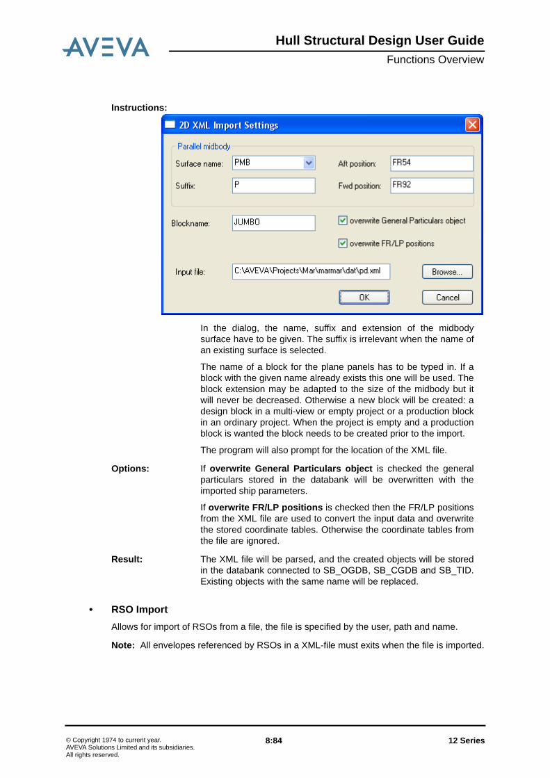
Hull Structural Design User GuideFunctions Overview
• RSO ImportAllows for import of RSOs from a file, the file is specified by the user, path and name.
Note: All envelopes referenced by RSOs in a XML-file must exits when the file is imported.
Instructions:
In the dialog, the name, suffix and extension of the midbodysurface have to be given. The suffix is irrelevant when the name ofan existing surface is selected.
The name of a block for the plane panels has to be typed in. If ablock with the given name already exists this one will be used. Theblock extension may be adapted to the size of the midbody but itwill never be decreased. Otherwise a new block will be created: adesign block in a multi-view or empty project or a production blockin an ordinary project. When the project is empty and a productionblock is wanted the block needs to be created prior to the import.
The program will also prompt for the location of the XML file.
Options: If overwrite General Particulars object is checked the generalparticulars stored in the databank will be overwritten with theimported ship parameters.
If overwrite FR/LP positions is checked then the FR/LP positionsfrom the XML file are used to convert the input data and overwritethe stored coordinate tables. Otherwise the coordinate tables fromthe file are ignored.
Result: The XML file will be parsed, and the created objects will be storedin the databank connected to SB_OGDB, SB_CGDB and SB_TID.Existing objects with the same name will be replaced.
12 Series 8:84© Copyright 1974 to current year.AVEVA Solutions Limited and its subsidiaries. All rights reserved.

Hull Structural Design User GuideFunctions Overview
8.5.2 Export
Figure 8:17. The XML Export Menu.
• Surface Export
• Structural Design Export
Purpose: To create an XML file containing surface data according to theTXSUR schema.
Prerequisites: The project has to contain main surface and/or reference surfaceinformation. The information is fetched from the databankconnected to SB_TID.
Instructions: Select MainSurface to be used. Empty or Cancel means moveon to ReferenceSurface selection. Select direction of curves, X orZ.Give curve interval on the form[Start],[Step],[Stop]>. Several intervals can be given.Select Cancel in the Select direction dialog to proceed. SelectReferenceSurface to be used. Wildcards are accepted.
Options: None available
Result: A file containing XML output of the information selected is created.
Purpose: To create an XML file containing general ship data according tothe TXHBD schema.
Prerequisites: The project has to contain compartments and/or generalparticulars information and transverse sections. The information isfetched from the databank connected to SB_TID and SB_OGDB.
12 Series 8:85© Copyright 1974 to current year.AVEVA Solutions Limited and its subsidiaries. All rights reserved.

Hull Structural Design User GuideFunctions Overview
• Hull Steel Export
• RSO ExportAllows for export of all existing RSOs to be exported to file, the file is specified by the user,path and name.
Instructions: • Select the different categories by ticking the boxes.• Key in the names of the spaces, comma separated, that
should be exported, if any. Wildcards are allowed. A SpaceWorld or Arrangement name has to be given.
• Key in the names of the compartments, comma separated,that should be exported, if any. Wildcards are allowed.
• Key in the frame numbers, comma separated, to beintersected. The frames can be in frame format (FR 25),frame offset (FR25-200) or absolute coordinate (27500).
• Key in the names of the compartments that should beexported, if any. Wildcards are allowed, and selections canbe repeated until all wanted compartments are selected.
• The selection is then ended with an empty selection. Give afile name for the resulting file.
Options: None available
Result: A file containing XML output of the information selected is created.
Purpose: To create an XML file containing Hull Steel data according to theTXHSTL-R schema.
Prerequisites: The project has to contain a hull steel model as planar or curvedpanel objects. The information is fetched from the databanksconnected to SB_OGDB and SB_CGDB.
Instructions: On the first page of the dialog blocks or panels in the tree view canbe picked and added to the right side to be included in theexported XML file. Also the name of the output file can be chosen.
Options: On the second page Idealization can be activated. Optionally thesnap distance can be set and Joint Lines can be added.
Result: A file containing XML output of the information selected is created.
12 Series 8:86© Copyright 1974 to current year.AVEVA Solutions Limited and its subsidiaries. All rights reserved.

Hull Structural Design User GuideFunctions Overview
8.6 Functions in the Analysis Menu
Figure 8:18. The Analysis Menu.
8.6.1 Section Modulus
Purpose: To calculate the total area, height of the neutral axis, moment ofinertia and the section modulus at the keel and deck for a cross-section of the ship at a given position along the X-axis of the ship.
Prerequisites: A cross-section view at the desired position must exist.
Instructions: All hull items involved in the calculations are collected using anindicate cross-section view. Once the collection is made, all basicdata are presented in a dialogue and the user is allowed to definefactors on individual items that should not be considered fully.When the OK button leaves the collection dialogue, the results arepresented.
12 Series 8:87© Copyright 1974 to current year.AVEVA Solutions Limited and its subsidiaries. All rights reserved.

Hull Structural Design User GuideFunctions Overview
8.6.2 Weld Calculation
Options: The involved items are presented in dialogues and lists with theirAVEVA Marine name. The Functional Description on panel levelcan be selected to be presented instead (if existing). This option isselected by setting the logical SBH_SECMOD_FD to any value.
The resulting CSV files are named as specified below using arunning number.The running number is by default locally initialisedto 1 at the start of a session and resulting files will get runningnumbers 1, 2 etc. Global running numbers can be selectedinstead, giving a resulting files a unique 6-digit number within aproject. An ASCII file assigned to the logical variableSBH_SECMOD_NAMES controls the global running numbers.The setup of this file is described in Manufacturing / ProductionProgram Interface / Automatic Naming of Drawings.
Result: The calculated values for the complete collection of items arepresented in the drawing. The neutral axis is draw together withcalculated data and the information can be shown or hidden usingthe function Planar > View > Properties.
If the user has changed any factors for individual items, thisinformation is stored with the selected view (in the drawing) andthese values are used the next time a Section Modulus calculationis made on this view.
The set of data and all calculations are presented in a CSV fileaccessible via the Log Viewer. The names of the resulting CSVfiles are SEC_MOD_<X-position>_<runningnumber>.csv, e.g. if calculations are made on a view in FR54the resulting file name may become SEC_MOD_FR54_1.csv.All resulting files will be placed on the directory assigned to thelogical SB_SHIPPRINT.
Purpose: To evaluate all connections within selected model blocks and topresented the type of weld and length of weld in a CSV file.
Prerequisites: None
Instructions: Select one or many hull blocks to be evaluated.
Options: None available
Result: The results will be presented on the screen and can be furtherprocessed using the CSV file presented in the Log Viewer.
12 Series 8:88© Copyright 1974 to current year.AVEVA Solutions Limited and its subsidiaries. All rights reserved.
Hull Structural Design User GuideFunctions Overview
8.6.3 Block Preliminary WCOG
Purpose: To support the user in the definition of the hull production blockstructure. The function estimates the weight and centre of gravityof the steel contents within hull blocks, created by a fictive blockdivision of the hull model. The fictive block division is achieved bydividing the complete hull model by a number of axis-alignedboxes given within a comma-separated input file.
The input file can have the following three different formats:
1. <Type(D or P)>, <Name> ,<Nom. Aft>,<Nom. Stbd>,<Nom.Bot>,<Nom. For>,<Nom. Port>,<Nom. Top>,<Encl. block>
2. The full input format as specified in Basic Design->FunctionOverview->Functions in the Project Menu->Block->Block -Create from CSV
3. A file with block names, one block name per row.
In all the three alternatives, the first row of the file must be acomma-separated headline, from which the input format can bedecided, e.g. if file format alternative number 3 is used, then theheadline shall consist of only one word without any commas.
The calculation result is presented by adding the calculated valuesto the given comma-separated file at the end of each row. Thefunction can be used iteratively, making changes to the boxinformation and re-running using the same file. If the file formatalternative 2 is used and the result from this calculation isaccepted, production blocks can be generated using the same fileas input.
The calculations are done by intersecting the hull model by thegiven boxes and then calculating the weight and centre of gravityof the hull items in each box. A fixed density of 7.84E-6 is used.The actual material definition of the hull is not considered.
The intention of the function is support in the definition of aproduction block structure and design blocks are therefore notconsidered.
Prerequisites: An input file, preferable placed on the directory assigned toSB_SHIPDATA, must exist.
Instructions: Select an input file in the displayed dialogue.
Options: None available.
Result: The resulting CSV file can be viewed using the Log Viewer.
12 Series 8:89© Copyright 1974 to current year.AVEVA Solutions Limited and its subsidiaries. All rights reserved.

Hull Structural Design User GuideFunctions Overview
8.6.4 WCOG
8.6.5 Material List
Purpose: To present the weight and centre of gravity of a number ofselected hull panels.
The calculations are made in two steps, first one when storing thepanel and second when the panel is split into production parts.The calculation made when storing the panel does not considerany production related information (bevel gaps, excess, etc.).Furthermore, notches and cutouts in stiffeners are not consideredin this first calculation.
Prerequisites: None
Instructions: Select one or many hull objects from the object dialogue or bygraphical picking from the drawing
Options: Toggle between selection of view and panel when makinggraphical picking
Result: The results will be presented on the screen and can be furtherprocessed using the CSV file presented in the Log Viewer.
Purpose: To present the material estimates (plates and profiles) of anumber of selected hull panels.
The material information is extracted from the model objects,independently of if production parts are available or not.
Prerequisites: None
Instructions: Select one or many hull objects from the object dialogue or bygraphical picking from the drawing.
Options: The resulting lists are presented in a CSV format. This can bechanged into a fixed format list by changing the file extension ofthe output files for Material Lists in the set-up file. The set-up file(applications.xml) controls all jobs executed via the LogViewer.
Result: The content of the lists is the same as in the lists for MaterialOrdering of Bars and Material Ordering of Plates (seeMiscellaneous Hull Functions / Material Ordering), but presentedas CSV files and possible to customize by the user.
12 Series 8:90© Copyright 1974 to current year.AVEVA Solutions Limited and its subsidiaries. All rights reserved.

Hull Structural Design User GuideFunctions Overview
8.6.6 Painting Areas
8.6.7 Idealize Model
Purpose: To generate painting area rooms and to initialise the areacalculations of these rooms.
Prerequisites: None.
Instructions: The function brings in all the Painting Rooms from the databankand presents them in a tree-type dialogue.
New rooms can be created, using the right-button of the mouse orexisting rooms can be modified.
TID Compartments can be used to define the painting roomtogether with additional limits.
Once the room definition is done, the room calculations can beperformed by marking the room in question and once again usingfunctions on the right-button menu.
The calculations are made without painting definitions. Thepresented results can be used for area analysis only.
Options: None available
Result: The resulting CSV file can be viewed using the Log Viewer.
Purpose: To create a block containing idealized panels as a preparation forcreating a Finite Element model
Prerequisites: A FEMWLD element must exist. Block with panels must exist.
Instructions: On the first pane select the blocks and/or panel to be included inthe FE model. Optionally a limiting box can be defined cutting outa portion of the selected model objects.
The second pane contains parameters used in creation of theidealized model and also later when making the FE model. TheType of Analysis section gives possibilities to save up to fourdifferent sets of parameters. The Intended Element size hasimpact mainly in the later stage when the FE model is created.
The lower half of the pane contains settings per component type. Itis possible to ignore any component type unconditionally ordepending on its size. For stiffeners, pillars and flanges maximumdistances are given within which the ends can snap to thesurroundings.
12 Series 8:91© Copyright 1974 to current year.AVEVA Solutions Limited and its subsidiaries. All rights reserved.

Hull Structural Design User GuideFunctions Overview
8.6.8 Create FE Model
The setting should be saved before starting the idealizationprocess.
The default settings can be brought back.
Result: A special kind of block containing idealized panels is created andstored.
Purpose: To create or recreate a Finite Element model from an Idealizedblock or to refine an existing FE model.
Prerequisites: An idealized block or an existing FE model in case of refinement.
Instructions: Checking Recreate FE geometry will create/recreate the FEmodel from the idealized block.
Divide shell elements will subdivide elements with a highernumber of node points than the specified one. Elements will not bedivided if it creates new elements with corner angles outside thegiven deviation from a right angle or if lines are created shorterthan the given factor multiplied by the intended element size givenwhen creating the idealized block.
Combine shell elements will prevent narrow shell elements byremoving them if two parallel sides are smaller than the givenlength factor times the intended element size. Note that this factormust be smaller than the one for "Divide shell elements".
Connect FE model will connect all node points and lines that arecloser than the given Distance tolerance.
Remove transition step is a special option for connection pointsof sloped panels and planar panels such as cambered decks. Thestep is ignored when the distance of the points is smaller than thegiven tolerance. The girder in the transition has to be indicated bya special functional code.
Unwarp shell elements allows the user to have control over shellelement warping. A four sided face maybe somewhat warped. Inorder to have desirable meshes without warnings and errors, amaximum warping factor should be defined within a certain limit.
12 Series 8:92© Copyright 1974 to current year.AVEVA Solutions Limited and its subsidiaries. All rights reserved.

Hull Structural Design User GuideFunctions Overview
8.6.9 Export FE Model to ANSYS APDL
8.6.10 Export FE Model to Patran PCL
8.7 Right Click Context MenusA quick way to perform certain actions on objects in the drawing is by indicating and use theright-click. The context menu alternative depends on which object type the user has clickedon.
• RSOsThe following context menu is presented when right-clicking an RSO in the 2D canvas:
Divide, Combine Connect and Unwrap can be applied to anexisting FE model refining it further.
Image objects can be selected for shells, beams and trusses. Alsoan object showing the shell elements with corner angles outsidethe tolerances can be created.
Result: An FE model is created and attached to the idealized block.Various image objects are created and stored. They can beinserted in the picture as FE Images. Their names are derivedfrom the idealized block name prefixed with _FGS for the shellimage, _FGB for the beam image, _FGT for the truss image and_FGA for the angle image.
Purpose: To create an ANSYS command file in apdl format from an FEmodel.
Prerequisites: An idealized block with an attached FE model must exist.
Instructions: Select the idealized block and specify the name of the apdl file.
The user can choose between old element types and current-technology types. It is recommended to use the newer types.
Result: An ANSYS apdl file.
Purpose: To create a Patran session file in PCL format from an FE model.
Prerequisites: An idealized block with an attached FE model must exist.
Instructions: Select the idealized block and specify the name of the ses file.
Result: A Patran ses file.
12 Series 8:93© Copyright 1974 to current year.AVEVA Solutions Limited and its subsidiaries. All rights reserved.

Hull Structural Design User GuideFunctions Overview
The selected function, described above, is performed on the right-clicked RSO
• BlocksThe following context menu is presented when right-clicking a block in the 2D canvas:
The selected function, described above, is performed on the right-clicked block.
12 Series 8:94© Copyright 1974 to current year.AVEVA Solutions Limited and its subsidiaries. All rights reserved.
Hull Structural Design User GuideDefault File of Structural Design
9 Default File of Structural Design
The Structural Design module can to some respect be controlled by a number of defaultparameters. These parameters should be defined in a file named sj700.sbd and aredescribed in this chapter.
Note: The default parameters defined for Planar Modelling and Curved Modelling are alsorelevant for Structural Design.
As for all other interactive Marine modules the general default file given by the environmentvariable SBD_DEF1 is valid. This default file is described in User Guide Marine Drafting /Operator’s Instructions / Defaults.
PROD_PAN_VIEW
Relevant only in a multi-view project. If set, the system starts in production view mode. If notset the system starts in design view mode for a multi-view project.
MIN_PLA_WIDTH = <width>
Minimum panel plate strip width used when cutting a panel in two. If the cut would give aplate strip narrower than the given value, no cut is made. If not given the value 50 mm willbe used.
MIN_STI_LENGTH = <length>
Minimum stiffener length used when cutting a panel in two. If the cut would give a stiffenershorter than the given value, the stiffener is not divided. If not given the value 100 mm willbe used.
PAN_SPLIT_ECUT_FLATBAR = <endcut>, <endcut>, …
PAN_SPLIT_ECUT_BULB_LBAR = <endcut>, <endcut>, …
PAN_SPLIT_ECUT_TBAR = <endcut>, <endcut>, …
PAN_SPLIT_ECUT_BUILT_TBAR = <endcut>, <endcut>, …
Additional endcut types used when defining stiffener offsets in Block Division (see BlockDivision).
BLOCK_DIV_SSTI_OVER = <dist>
Shell Stiffener Overlap used in Block Division of Curved Panels. This will move the cuttingplane to make Shell Stiffeners to be cut at a distance from the edge of the Curved Panel. Ifnot defined, -50 mm will be used.
12 Series 9:1© Copyright 1974 to current year.AVEVA Solutions Limited and its subsidiaries. All rights reserved.

Hull Structural Design User GuideDefault File of Structural Design
12 Series 9:2© Copyright 1974 to current year.AVEVA Solutions Limited and its subsidiaries. All rights reserved.

Hull Structural Design User GuideBatch Utilities
10 Batch Utilities
10.1 Block Division
10.1.1 GeneralThis program is used to make the block division in batch instead of interactive. Details arespecified below.
10.1.2 Set-up of ProgramThe name of the executable of this program is sj701. It communicates via an input file andresulting files. The program is normally activated through the Log Viewer (JL) where thefollowing set-up is required:
10.1.3 InputThe program requires information about which block to split, where to split it and where toplace the resulting panels. This information can be given in an input file, with name assignedto SB_INPUT1.
The input file should follow the following syntax:
MAIN_BLOCK, <block_name>;
This statement can only be given once and it is the main block <block_name> this it tobe divided.
FORCE { /MAIN | /CURRENT };
This statement indicates where to place the resulting panels that are intersected by ablock limit. MAIN means that the panel should remain in the original block. CURRENTwill place the panel in the block that is currently handled by the system. This statementshould only be given once. Default is CURRENT.
KEEP { /YES | /NO };
Name recognised by JL: Hull Block Division
Logical variable JL set-up and explanation
SB_INPUT1 Input file to be set up with extension .dat in JL
SB_OUTPUT1 Output file with run-time information. To be set up in JL asfirst output file with extension .log
12 Series 10:1© Copyright 1974 to current year.AVEVA Solutions Limited and its subsidiaries. All rights reserved.

Hull Structural Design User GuideBatch Utilities
This statement indicates whether the original panels will be kept or deleted. Keptpanels will loose all topological data and will no be available for further production orany changes. This statement should only be given once. Default is NO.
This statement is to define a plane where to split the main block. The statement canbe repeated any number of times and all planes will be handled within the main block.The statement is optional.
MODEL_TYPE { /ALL | /PLANE_PANELS | /CURVED_PANELS };
This statement selects whether plane or curved or both kinds of panels are to behandled. The statement is optional.
SEAM, <seam_name>;
With this statement it is possible to use already existing block seams. The statementcan be repeated any number of times and all seams will be handled within the mainblock. The statement is optional.
RSO, <RSO_name>;
With this statement it is possible to use an RSO as a block divider. This optionalstatement can be repeated any number of times.
STORED_PLANE, <plane_name>;
This statement adds already defined planes to the cutters. The statement can berepeated any number of times. The statement is optional.
FUNCTIONAL_BLOCK_SEAM { /CREATE | /CREATE_ONLY | /USE };
This statement defines the handling of Block Seams on Design panels. If a Designblock is divided into Production blocks the Block Seams can either be created (/CREATE) or used as cutters (/USE). Block Division can also be used to only createBlock Seams from cutters without creating new panels. In this case /CREATE_ONLYis used. For other blocks that Design blocks this statement is irrelevant.
PROFILE_END /CUTTER=<cutter_name> /PANEL=<panel_name>
/DIRECTION={PS | SB | AFT | FOR | TOP | BOT} /SHIFT=<value> /SLANT=<value>
/FLANGE_SHIFT=<value>/NOTCH=<notch_designation>
/FLANGE_NOTCH=<notch_designation>;
This statement defines the stiffener end details relative to the intersection between thepanel and the cutter. The new stiffeners on both sides of the cut will get matching enddefinitions.
<cutter_name> is the name of one of the cutters previously defined. If not given theoffset values are supposed to be valid for all cutters and all intersected panels.
<panel_name> is the name of an panel intersected by the given cutter. Irrelevant if nocutter is given. If a panel is not given the offset values are supposes to be valid for allthe panels intersected by the cutter.
12 Series 10:2© Copyright 1974 to current year.AVEVA Solutions Limited and its subsidiaries. All rights reserved.

Hull Structural Design User GuideBatch Utilities
The direction indicates along which principal axis the values are given.
The shift and slant values are given in mm and the notch designation according to thestandards. Note that the values given must translate to a set of connection codes andendcut codes. FLANGE_SHIFT and FLANGE_NOTCH are only valid for built profiles.If not given the values are set to zero/empty. See chapter Block Division for moredetails.
BLOCK, <res_block>;
This statement defines the receiving block where panels in the main block will beplaced after the split. The statement can be repeated any number of times.
• Example of an Input File:
10.1.4 Output FilesThe result of the interpretation of the input file will be presented in a file assigned to thelogical SB_OUTPUT1.
The logfile will contain informational messages and error messages.
10.2 Extracting RSO Information General
This program is used to extract properties of the RSOs in the current project. The extractedinformation is presented in a comma-separated file (CSV), which can be updated manually.The updated file can be used as input by another AVEVA Marine program (Update RSOsfrom CSV File), which updates the properties of RSOs.
Set-Up of the Program
The name of the executable of this program is sj703. It communicates with the user via aresult file. The program is normally activated through the Log Viewer (JL), recognized by thename Extract RSOs to CSV. The following set-up is required
Example:
MAIN_BLOCK, 'BLOCK1';
FORCE /MAIN;
KEEP /NO;
PLANE, X=FR58+400;
PLANE, X=FR72-200;
SEAM, AAS44;
BLOCK, AABLOCK1;
BLOCK, AABLOCK2;
BLOCK, AABLOCK3;
12 Series 10:3© Copyright 1974 to current year.AVEVA Solutions Limited and its subsidiaries. All rights reserved.

Hull Structural Design User GuideBatch Utilities
If the program is activated in other ways (e.g. via a windows script), the CSV file name maybe given as an argument to the program at execution, e.g. sj703 c:\temp\rso.csv.
Input
No input is needed to run this program
Output
The output file is organized as a comma-separated file. Each extracted RSO will generatetwo rows with the following layout:
Logical variable JL set-up and explanation
SB_OUTPUT1 Output file with extracted RSO information. To be set up in JL asfirst output file with extension .csv
Column name Description
Function Functional description of the RSO given as a code. Codes to beused can be found in Hull Model Concepts / Functional Descriptions/ Pre-Defined Functional Descriptions.
The second row contains the envelope name.
Tight If structure shall be defined as water-tight or not. Possible valuesare YES or NO.
The second row contains a boundary of the RSO, given atdefinition. Bounding side is SB if RSO in X plane, TOP if RSO in Yplane and AFT if RSO in Z plane.
Name Name of the RSO.
The second row contains a boundary of the RSO given, atdefinition. Bounding side is PS if RSO in X plane, BOT if RSO in Yplane and FOR if RSO in Z plane.
Face Face number of the RSO.
The second row contains a boundary of the RSO given, atdefinition. Bounding side is TOP if RSO in X plane, AFT if RSO in Yplane and SB if RSO in Z plane.
Principle Plane Possible vales or X, Y, Z or NO.
The second row contains a boundary of the RSO given, atdefinition. BOT if RSO in X plane, FOR if RSO in Y plane and PS ifRSO in Z plane.
Coord. Coordinate value defining the position of the plane. If not in aprinciple plane, this value is undefined.
Second row is blank.
12 Series 10:4© Copyright 1974 to current year.AVEVA Solutions Limited and its subsidiaries. All rights reserved.

Hull Structural Design User GuideBatch Utilities
Auto Gen. Information if steel shall be automatically generated on this face ofthe RSO. Possible values are YES or NO.
Second row is blank.
Mtrl Side Information about material side for automatically generated panels.Possible values are PS, SB, BOT TOP, AFT, FOR and MID.
Second row is blank.
Mtrl Th. Plate material thickness for automatically generated panels.
Second row is blank.
Mtrl Qual. Plate material quality for automatically generated panels.
Second row is blank.
Auto Stiffeners Information if stiffeners shall be generated on an automaticallygenerated panel. Possible values are YES or NO.
Second row is blank.
Stiffener Side Information about stiffener side for automatically generatedstiffeners. Possible values are PS, SB, BOT TOP, AFT and FOR.
Second row is blank.
Profile Type Profile type given as a code. Available codes can be found in HullModel Concept / Standards / Survey of Design Standards in AVEVAHull.
Second row is blank.
Profile Dim. Profile dimension given using delimiter *, e.g. 220*12.
Second row is blank.
Limits/Stiff. Ends
(the column isrepeated for thenumber of limitsbounding the RSOface)
The first row contains the name of the RSO limit. Values can beeither a surface name, an RSO name or a face number. If a facenumber, the current face is limited by another face within the sameRSO. A face number is given with prefix FACE_, e.g. FACE_3.
The second row contains end connection data for stiffeners. End cutand connection code is given using keyword as defined by the set-up described in Hull Model Concept->Standards->Survey of DesignStandards in Hull->Stiffener Connections. Brackets are given usinga bracket instance, further described in Hull Model Concept->Standards->Survey of Design Standards in AVEVA Hull->Brackets. The bracket instance is given after the stiffenerconnection separated by a slash (/).
Example of this column:
TTPHULL
SNIPE/B16
Column name Description
12 Series 10:5© Copyright 1974 to current year.AVEVA Solutions Limited and its subsidiaries. All rights reserved.

Hull Structural Design User GuideBatch Utilities
10.3 Updating RSO Information General
This program is used to update the properties of existing RSOs or to create new RSOs. Thecreation of new RSOs is restricted to RSOs in principle planes with one face only. Morecomplicated RSOs must be modelled using interactive tools in Structural Design or InitialDesign Surface/Compartment. Definition data for a new RSO is the envelope name andboundary information found in the second row on each RSO.
The updates shall be made in a CSV file, previously extracted using AVEVA Marineprogram Extract RSOs to CSV.
Set-Up of the Program
The name of the executable of this program is sj704. It communicates with the user via aninput file. The program is normally activated through the Log Viewer (JL), recognized by thename Update RSOs from CSV file. The following set-up is required
If the program is activated in other ways (e.g. via a windows script), the CSV file name maybe given as an argument to the program at execution, e.g. sj704 c:\temp\rso.csv.
Input
A comma-separated file. The layout of the file is described in Extracting RSO Information
Output
The RSOs are updated with new properties. New RSOs are stored in the database.
10.4 Generate Steel from RSOGeneral
The program is used to generate simple panels on RSOs with modelling properties added.Prerequisite for the modelling is that a functional description is added and that automaticgeneration is asked for via the RSO properties. Further description can be found inGenerate Panels in Chapter Functions Overview.
Set-Up of the Program
The name of the executable of this program is sj705 and the program is normallyactivated through the Log Viewer (JL), recognized by the name Generate Steel from RSO.
Input
All input is fetched from the RSOs and the properties stored with these RSOs. Theproperties are updated using either the program Update RSOs from CSV file or using the
Logical variable JL set-up and explanation
SB_INPUT1 Input file with updated RSO information. To be set up in JL as firstinput file.
12 Series 10:6© Copyright 1974 to current year.AVEVA Solutions Limited and its subsidiaries. All rights reserved.
Hull Structural Design User GuideBatch Utilities
interactive functions within Structural Design (see Properties in Chapter FunctionsOverview.
Output
Panels are generated.
10.5 Create/Remove Design Blocks and PanelsGeneral
The program creates respectively removes Design blocks and panels depending on inputargument. It should be used with caution and it is recommended that OGDB is backed upbefore execution.
Set-Up of the Program
The name of the executable is sj706. Default action is Create, if input argument /REMOVEis supplied the action is Remove. The program can be activated through the Log Viewer bythe names Create Design Project and Remove Design Project. To avoid usage bymistake, the remove option has to be activated in the control file for the Log Viewer by thesystem administrator.
Input
None.
Output
Create An input file is requested with definition of Design Blocks, using thesame syntax as when creating blocks in batch. Further informationcan be found in Block - Create from CSV in Chapter FunctionsOverview.
All existing blocks are changed to be Production blocks belongingthe Design blocks that are created from the input file. All existingordinary panels are changed to Production panels and correspondingDesign panels are created in respective Design block.
Remove All Design panels and blocks are deleted. All Production blocks andpanels are changed to ordinary panels.
12 Series 10:7© Copyright 1974 to current year.AVEVA Solutions Limited and its subsidiaries. All rights reserved.

Hull Structural Design User GuideBatch Utilities
12 Series 10:8© Copyright 1974 to current year.AVEVA Solutions Limited and its subsidiaries. All rights reserved.