Embed Size (px)
Citation preview

1
C20X & C50X SERIES
www.NightOwlSP.com
USER’S MANUAL
2
Night Owl’s C20X and C50X Series DVRs are compatible with most analog cameras (400-900TVL), Night Owl’s Analog HD (AHD) and HD Analog (HDA) cameras:
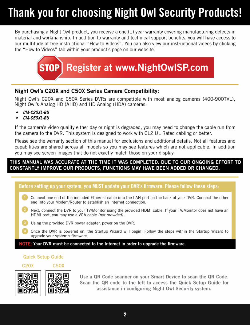
Thank you for choosing Night Owl Security Products!
Use a QR Code scanner on your Smart Device to scan the QR Code. Scan the QR code to the left to access the Quick Setup Guide for
assistance in configuring Night Owl Security system.
By purchasing a Night Owl product, you receive a one (1) year warranty covering manufacturing defects in material and workmanship. In addition to warranty and technical support benefits, you will have access to our multitude of free instructional “How to Videos”. You can also view our instructional videos by clicking the “How to Videos” tab within your product’s page on our website.
Register at www.NightOwlSP.com
Night Owl’s C20X and C50X Series Camera Compatibility:
Connect one end of the included Ethernet cable into the LAN port on the back of your DVR. Connect the other end into your Modem/Router to establish an Internet connection.
Next, connect the DVR to your TV/Monitor using the provided HDMI cable. If your TV/Monitor does not have an HDMI port, you may use a VGA cable (not provided).
Using the provided DVR power adapter, power on the DVR.
Once the DVR is powered on, the Startup Wizard will begin. Follow the steps within the Startup Wizard to upgrade your system’s firmware.
Before setting up your system, you MUST update your DVR’s firmware. Please follow these steps:
NOTE: Your DVR must be connected to the Internet in order to upgrade the firmware.
1
2
3
4
If the camera’s video quality either day or night is degraded, you may need to change the cable run from the camera to the DVR. This system is designed to work with CL2 UL Rated cabling or better.
Please see the warranty section of this manual for exclusions and additional details. Not all features and capabilities are shared across all models so you may see features which are not applicable. In addition you may see screen images that do not exactly match those on your display.
THIS MANUAL WAS ACCURATE AT THE TIME IT WAS COMPLETED. DUE TO OUR ONGOING EFFORT TO CONSTANTLY IMPROVE OUR PRODUCTS, FUNCTIONS MAY HAVE BEEN ADDED OR CHANGED.
Quick Setup Guide
C20X C50X
• CM-C20XL-BU
• CM-C50XL-BU

3
TABLEOF CONTENTS
4
Table of ContentsChapter 1: FCC Warnings . . . . . . . . . . . . . . . . . . . . . . . . . . . . . . . . . . . . . . . . . . . . . .7Chapter 2: Safety Instructions . . . . . . . . . . . . . . . . . . . . . . . . . . . . . . . . . . . . . . . . . .9Chapter 3: Specifications . . . . . . . . . . . . . . . . . . . . . . . . . . . . . . . . . . . . . . . . . . . .11 3.1 System Requirements . . . . . . . . . . . . . . . . . . . . . . . . . . . . . . . . . .11 3.2 Package Contents . . . . . . . . . . . . . . . . . . . . . . . . . . . . . . . . . . . . .11 3.2.1 DVR Diagram . . . . . . . . . . . . . . . . . . . . . . . . . . . . . . . . . . . .12 3.2.2 Camera Diagram . . . . . . . . . . . . . . . . . . . . . . . . . . . . . . . . . .13 3.2.3 Mouse Diagram . . . . . . . . . . . . . . . . . . . . . . . . . . . . . . . . . . .13Chapter 4: Camera Installation . . . . . . . . . . . . . . . . . . . . . . . . . . . . . . . . . . . . . . . . .15 4.1 Video/Audio . . . . . . . . . . . . . . . . . . . . . . . . . . . . . . . . . . . . . . . . .15 4.2 Power . . . . . . . . . . . . . . . . . . . . . . . . . . . . . . . . . . . . . . . . . . . . .16 4.2.1 Standard Camera Power . . . . . . . . . . . . . . . . . . . . . . . . . . . . .16 4.3 Mounting the Cameras . . . . . . . . . . . . . . . . . . . . . . . . . . . . . . . . . .17Chapter 5: DVR Installation . . . . . . . . . . . . . . . . . . . . . . . . . . . . . . . . . . . . . . . . . . .20 5.1 Connecting to a TV (via HDMI) . . . . . . . . . . . . . . . . . . . . . . . . . . . .20 5.2 Power . . . . . . . . . . . . . . . . . . . . . . . . . . . . . . . . . . . . . . . . . . . . .21Chapter 6: Getting Started . . . . . . . . . . . . . . . . . . . . . . . . . . . . . . . . . . . . . . . . . . . .23 6.1 Startup Wizard . . . . . . . . . . . . . . . . . . . . . . . . . . . . . . . . . . . . . . .23 6.1.1 Camera Test . . . . . . . . . . . . . . . . . . . . . . . . . . . . . . . . . . . . .24 6.1.2 Network Check . . . . . . . . . . . . . . . . . . . . . . . . . . . . . . . . . . .24 6.1.3 Firmware Check . . . . . . . . . . . . . . . . . . . . . . . . . . . . . . . . . . .26 6.1.4 Password Creation . . . . . . . . . . . . . . . . . . . . . . . . . . . . . . . . .27 6.1.5 Date and Time Setup . . . . . . . . . . . . . . . . . . . . . . . . . . . . . . .28 6.1.6 Night Owl Connect App . . . . . . . . . . . . . . . . . . . . . . . . . . . . .29 6.1.6 (a) Using Night Owl Connect . . . . . . . . . . . . . . . . . . . . . . . .30 6.1.6 (b) App Overview . . . . . . . . . . . . . . . . . . . . . . . . . . . . . . . .33 6.1.7 Password Verification . . . . . . . . . . . . . . . . . . . . . . . . . . . . . . .34 6.1.8 Camera/Channel Settings . . . . . . . . . . . . . . . . . . . . . . . . . . . .34 6.1.9 Camera Positioning . . . . . . . . . . . . . . . . . . . . . . . . . . . . . . . .35 6.1.10 Channel Configuration . . . . . . . . . . . . . . . . . . . . . . . . . . . . .35 6.1.11 Default View . . . . . . . . . . . . . . . . . . . . . . . . . . . . . . . . . . . .37 6.1.12 Helpful Links . . . . . . . . . . . . . . . . . . . . . . . . . . . . . . . . . . .38 6.1.13 Wizard Complete . . . . . . . . . . . . . . . . . . . . . . . . . . . . . . . . .38 6.2 Displays and Icons . . . . . . . . . . . . . . . . . . . . . . . . . . . . . . . . . . . .39 6.2.1 Login Screen . . . . . . . . . . . . . . . . . . . . . . . . . . . . . . . . . . . . .39 6.2.2 Live View (All Channels) . . . . . . . . . . . . . . . . . . . . . . . . . . . . .40 6.2.3 Right-Click Menu . . . . . . . . . . . . . . . . . . . . . . . . . . . . . . . . . .41 6.2.3 (a) Light Menu . . . . . . . . . . . . . . . . . . . . . . . . . . . . . . . . . .42 6.2.4 Menu Screen . . . . . . . . . . . . . . . . . . . . . . . . . . . . . . . . . . . . .43

5
Chapter 7: Menus and Settings . . . . . . . . . . . . . . . . . . . . . . . . . . . . . . . . . . . . . . . .45 7.1 General Menu . . . . . . . . . . . . . . . . . . . . . . . . . . . . . . . . . . . . . . . .46 7.1.1 Display . . . . . . . . . . . . . . . . . . . . . . . . . . . . . . . . . . . . . . . . .46 7.1.2 Network . . . . . . . . . . . . . . . . . . . . . . . . . . . . . . . . . . . . . . . .47 7.1.3 DDNS . . . . . . . . . . . . . . . . . . . . . . . . . . . . . . . . . . . . . . . . . .48 7.2 Cameras Menu . . . . . . . . . . . . . . . . . . . . . . . . . . . . . . . . . . . . . . .49 7.2.1 Settings . . . . . . . . . . . . . . . . . . . . . . . . . . . . . . . . . . . . . . . .49 7.2.2 Encode . . . . . . . . . . . . . . . . . . . . . . . . . . . . . . . . . . . . . . . . .50 7.2.3 Motion . . . . . . . . . . . . . . . . . . . . . . . . . . . . . . . . . . . . . . . . .51 7.2.4 Setting Detection Area . . . . . . . . . . . . . . . . . . . . . . . . . . . . . .53 7.3 Record Menu . . . . . . . . . . . . . . . . . . . . . . . . . . . . . . . . . . . . . . . .54 7.3.1 Schedule . . . . . . . . . . . . . . . . . . . . . . . . . . . . . . . . . . . . . . .54 7.3.2 Playback . . . . . . . . . . . . . . . . . . . . . . . . . . . . . . . . . . . . . . . .55 7.3.2 (a) Video Playback . . . . . . . . . . . . . . . . . . . . . . . . . . . . . . .55 7.3.2 (b) Right-Click Menu. . . . . . . . . . . . . . . . . . . . . . . . . . . . . .56 7.3.3 Exporting Recordings . . . . . . . . . . . . . . . . . . . . . . . . . . . . . . .58 7.4 Device Menu . . . . . . . . . . . . . . . . . . . . . . . . . . . . . . . . . . . . . . . .61 7.4.1 HDD . . . . . . . . . . . . . . . . . . . . . . . . . . . . . . . . . . . . . . . . . . .61 7.4.2 PTZ . . . . . . . . . . . . . . . . . . . . . . . . . . . . . . . . . . . . . . . . . . .62 7.4.2 (a) Using Control Method RS485 . . . . . . . . . . . . . . . . . . . . .62 7.4.2 (b) Using Control Method UTC (Up-The-Coax) . . . . . . . . . . . .63 7.5 System Menu . . . . . . . . . . . . . . . . . . . . . . . . . . . . . . . . . . . . . . . .64 7.5.1 General . . . . . . . . . . . . . . . . . . . . . . . . . . . . . . . . . . . . . . . .64 7.5.1 (a) DST . . . . . . . . . . . . . . . . . . . . . . . . . . . . . . . . . . . . . . .65 7.5.1 (b) NTP . . . . . . . . . . . . . . . . . . . . . . . . . . . . . . . . . . . . . . .65 7.5.2 Users . . . . . . . . . . . . . . . . . . . . . . . . . . . . . . . . . . . . . . . . . .66 7.5.2 (a) Modify User . . . . . . . . . . . . . . . . . . . . . . . . . . . . . . . . .67 7.5.3 Info . . . . . . . . . . . . . . . . . . . . . . . . . . . . . . . . . . . . . . . . . . .68 7.5.4 Log . . . . . . . . . . . . . . . . . . . . . . . . . . . . . . . . . . . . . . . . . . .69 7.6 Advanced Menu . . . . . . . . . . . . . . . . . . . . . . . . . . . . . . . . . . . . . .70 7.6.1 Maintain . . . . . . . . . . . . . . . . . . . . . . . . . . . . . . . . . . . . . . . .70 7.6.2 Events . . . . . . . . . . . . . . . . . . . . . . . . . . . . . . . . . . . . . . . . .71 7.6.3 Alarm Status . . . . . . . . . . . . . . . . . . . . . . . . . . . . . . . . . . . . .73 7.6.4 Auto Upgrade . . . . . . . . . . . . . . . . . . . . . . . . . . . . . . . . . . . .75Chapter 8: Glossary . . . . . . . . . . . . . . . . . . . . . . . . . . . . . . . . . . . . . . . . . . . . . . . . .77Chapter 9: Warranty . . . . . . . . . . . . . . . . . . . . . . . . . . . . . . . . . . . . . . . . . . . . . . . .79Chapter 10: Troubleshooting . . . . . . . . . . . . . . . . . . . . . . . . . . . . . . . . . . . . . . . . . .82Chapter 11: User Information . . . . . . . . . . . . . . . . . . . . . . . . . . . . . . . . . . . . . . . . .85Customer Support . . . . . . . . . . . . . . . . . . . . . . . . . . . . . . . . . . . . . . . . . . . .Back Cover
Night Owl’s DVRs are manufactured for quality and ease of use. As such, our DVRs contain menus designed for advanced users that should not be adjusted without having enhanced knowledge regarding the menu. In most cases the default settings allow for optimal functionality. The menus that should maintain the default settings are indicated with this icon.ADVANCED

6
CHAPTER 1FCC WARNINGS
7
Chapter 1: FCC Warnings
FCCThis device complies with Part 15 of the FCC Rules. Operation is subject to the following two conditions: (1) this device may not cause harmful interference and (2) this device must accept any interference received, including interference that may cause undesired operation.
FCC Compliance StatementThese limits are designed to provide reasonable protection against frequency interference in residential installation. This equipment generates, uses and can radiate radio frequency energy and if not installed or used in accordance with the instructions, may cause harmful interference to radio communication. However, there is no guarantee that interference will not occur in television reception, which can be determined by turning the equipment off and on. The user is encouraged to try and correct the interference by one or more of the following measures:
• Reorient or relocate the receiving antenna.
• Increase the separation between the equipment and the receiver.
• Connect the equipment into an outlet on a circuit different from that to which the receiver is connected.
• Consult the dealer or an experienced radio/TV technician for help.
The Federal Communications Commission warns the user that changes or modifications to the unit not expressly approved by the part responsible for compliance could void the user’s authority to operate the equipment.
CAUTION!

8
CHAPTER 2SAFETY
INSTRUCTIONS

9
Chapter 2: Safety Instructions
USE THE PROVIDED POWER ADAPTER.Do not use this product with a power source that applies more than the specified voltage.
NEVER INSERT METAL INTO THE DVR CASE OR ITS OPENINGS.Inserting metal into the DVR case may cause electric shock.
DO NOT OPERATE IN WET OR DUSTY AREAS.Avoid placing the DVR in areas such as a damp basement or dusty attic.
DO NOT EXPOSE THE DVR TO RAIN OR USE NEAR WATER.If the DVR accidentally gets wet, unplug it and contact technical support immediately.
KEEP PRODUCT SURFACES CLEAN AND DRY.To clean the outside case of the DVR, use a lightly dampened cloth. Do not use cleaning solutions or solvents.
DO NOT INSTALL NEAR ANY HEAT SOURCES.Do not install the DVR near any heat sources such as stoves, heat registers, radiators or electronics (including amplifiers) that produce heat.
UNPLUG THE DVR WHEN MOVING IT.Make sure that the DVR is unplugged before you move it. When moving this device, be sure to handle it with care.
MAKE SURE THERE IS GOOD AIR CIRCULATION AROUND THE DVR.This DVR uses an internal hard drive, which generates heat during operation for video storage. Do not block vents on the DVR, as these vents reduce the generated heat while the system is running. Place this product in well-ventilated area.
DO NOT ATTEMPT TO REMOVE THE TOP COVER.If you observe any abnormal operation, unplug the DVR immediately and contact technical support. Do not attempt to open the DVR to diagnose the cause of the problem.
HANDLE THE DVR CAREFULLY.If you drop the DVR on any hard surface, it may damage the device. If the DVR doesn’t work properly due to physical damage, contact an authorized dealer for repair.
IT IS RECOMMENDED TO USE YOUR DVR WITH AN UNINTERRUPTIBLE POWER SUPPLY (UPS).Connecting your DVR and cameras to a UPS allows continuous operation even during power outages.The run-time duration will depend on the rating of the UPS used.
You may be subjected to severe electrical shock if you remove the cover of the DVR.
CAUTION!

10
CHAPTER 3SPECIFICATIONS

11
Chapter 3: Specifications3.1 System Requirements
Please be sure that your PC/MAC® complies with the following specifications:
Please be sure that your mobile device complies with the following specifications:
4.2 Package Contents
THIS MANUAL WAS ACCURATE AT THE TIME IT WAS COMPLETED. DUE TO OUR ONGOING EFFORT TO CONSTANTLY IMPROVE OUR PRODUCTS, SPECIFICATIONS MAY HAVE BEEN ADDED OR CHANGED.
• PC Operating System: Windows® 10 and above• MAC Operating System: MAC OS X® 10.9 and above
• Android™: 4.2 and above• iOS®: 9 and above
NOTE: For best results, use the included Night Owl accessories. Third party accessories may not work properly.
NOTE: Monitor is requiredfor initial setup.
USBMouse (x1)
6 ft. HDMI (x1)
6 ft. Ethernet (x1)
Power Splitter(s)(1 per 4 cameras)
Monitor Router
Items Not Included
RESET LAN1 LAN2 LAN3 LAN4 WAN
Mounting Hardware
SafetyStickers
60 ft. Video/Power Cables (1 cable per camera)
DVR Power Adapter (x1)
Camera Power Adapter(s)
(1 per 4 cameras)
Camera(s)DVR
3.2 Package ContentsDISCLAIMER: Package contents vary by model number, please refer to your Quick Setup Guide for a complete list of contents.

12
QR Code QR Code
Once you have downloaded Night Owl Connect and connected your DVR to your router, you can network your DVR by scanning the QR code which is located on the top of the DVR.
FRONT VIEWC20X C50X
REAR VIEW
NOTE: While the front view may vary, the DVR rear view is the same for both C20X and C50X systems.
Video Inputs – Allows for the connection of BNC wired cameras. Wireless cameras connect to the DVR’s built-in Wi-Fi.
HDMI Output – Allows for the video connection. If the TV/Monitor has an HDMI input, connect the HDMI cable from the HDMI output port on the DVR to the HDMI input port on your TV/Monitor. NOTE: Preferred method.
VGA Output – Allows for the video connection. If the TV/Monitor has a VGA input, connect the VGA cable from the VGA output port on the DVR to the VGA input port on your TV/Monitor. (VGA Cable not included. VGA Port not available on all models.)
Audio Output – Allows for the connection of an amplified speaker using an RCA connector.
Audio Input – Allows for the connection of audio enabled cameras by connecting the white RCA plug to one of the audio inputs. After making the audio input connection, be sure to enable the audio function in the DVR’s menu interface. (VGA Cable not included)
USB Ports – Allows for the connections of a USB mouse and/or a USB flash drive. You will connect the included USB mouse to assist you in navigating the DVRs menu interface. You will connect a USB flash drive to download video files from the DVR and save them to your USB flash drive.
RJ-45 (Ethernet) Port – Used to connect the DVR to your router/modem via the included Ethernet cable.
Power Input – Used to connect the included 12V DC power supply.
1
2
3
4
5
6
7
8
1 2 3 6
74
85
3.2.1 DVR Diagram
Images used are for reference only. Your product may vary slightly depending on your model number.

13
Built-In Spotlight
1080p / 5MP ResolutionWide Viewing Angle 100ºNight Vision up to 100 ft.
3-Axis Mounting Bracket (Vandal-Proof Wire Camera Protection)
Video/Power Cables
CAMERA
4.2.3 Mouse Diagram
MOUSE
Live Viewing: Double-click the left button on any camera view in split-screen mode to bring it to full screen display.Double-click again to return to split-screen mode. Right-click to show the Right-Click Menu at the bottom of the screen. Right-clicking again will hide the Right-Click Menu.
In Setup: Left-click to make a selection. Right-click to cancel setup or return to previous screen.
To Enter Values: Move the cursor to a blank field and click the mouse. A virtual keyboard will appear which supports numbers, letters and symbols. The Shift function will access symbols in addition to upper case letters.
Connect all cameras locally before final placement to ensure that all components function properly.
3.2.2 Camera Diagram
3.2.3 Mouse Diagram

14
CHAPTER 4CAMERA
INSTALLATION
15
Camera
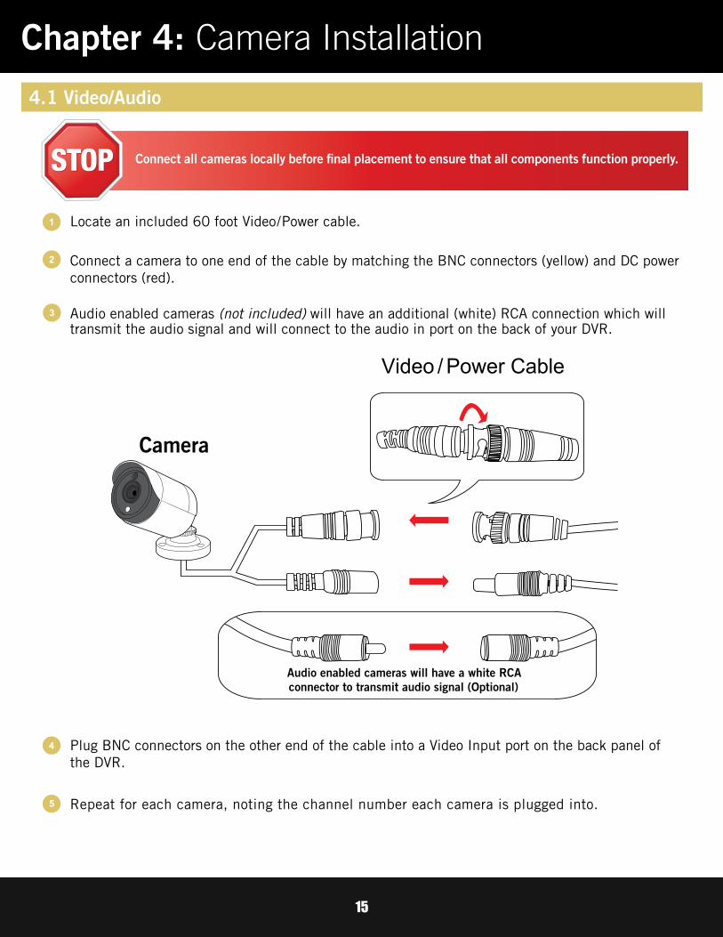
Chapter 4: Camera Installation
Connect a camera to one end of the cable by matching the BNC connectors (yellow) and DC power connectors (red).
Locate an included 60 foot Video/Power cable.
Audio enabled cameras (not included) will have an additional (white) RCA connection which will transmit the audio signal and will connect to the audio in port on the back of your DVR.
1
2
3
Repeat for each camera, noting the channel number each camera is plugged into.
4
5
Plug BNC connectors on the other end of the cable into a Video Input port on the back panel of the DVR.
4.1 Video/Audio
Connect all cameras locally before final placement to ensure that all components function properly.
16
4.2 Power
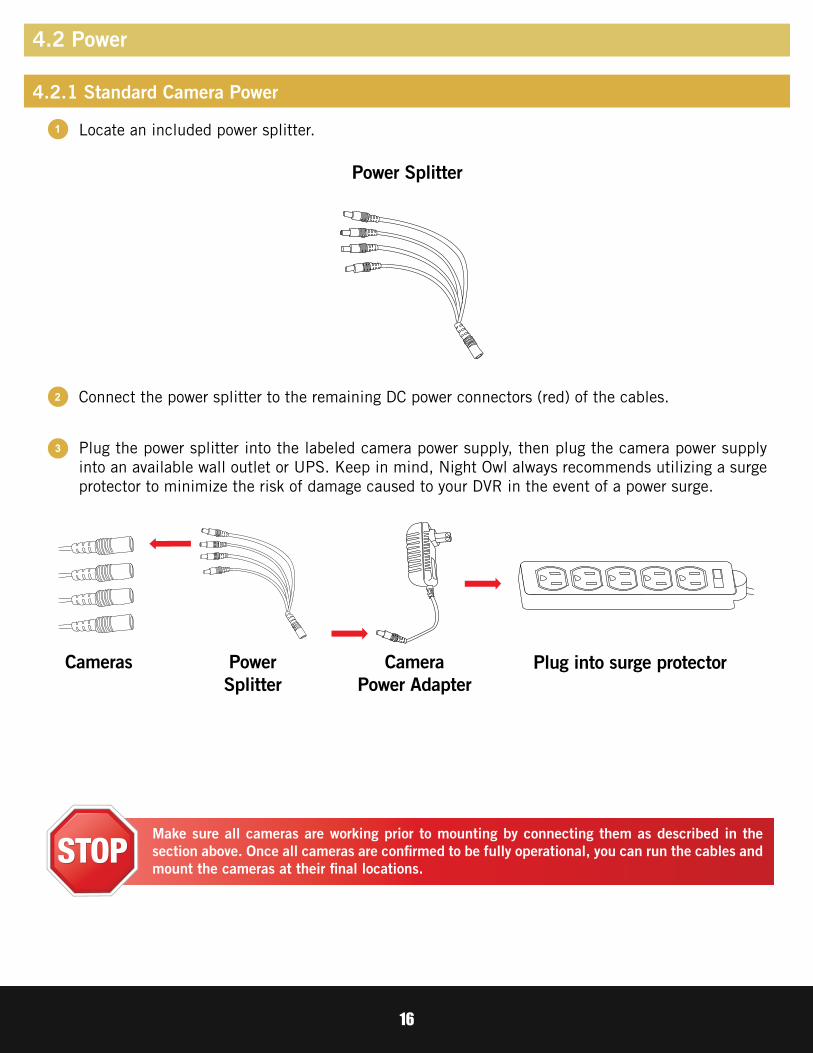
Locate an included power splitter.
Connect the power splitter to the remaining DC power connectors (red) of the cables.
Plug the power splitter into the labeled camera power supply, then plug the camera power supply into an available wall outlet or UPS. Keep in mind, Night Owl always recommends utilizing a surge protector to minimize the risk of damage caused to your DVR in the event of a power surge.
1
2
3
Plug into surge protectorCameras CameraPower Adapter
Power Splitter
PowerSplitter
Make sure all cameras are working prior to mounting by connecting them as described in the section above. Once all cameras are confirmed to be fully operational, you can run the cables and mount the cameras at their final locations.
4.2.1 Standard Camera Power
17
4.3 Mounting the Cameras
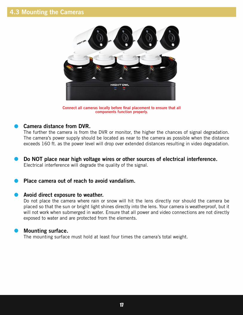
Camera distance from DVR.The further the camera is from the DVR or monitor, the higher the chances of signal degradation. The camera’s power supply should be located as near to the camera as possible when the distance exceeds 160 ft. as the power level will drop over extended distances resulting in video degradation.
Do NOT place near high voltage wires or other sources of electrical interference.Electrical interference will degrade the quality of the signal.
Avoid direct exposure to weather.Do not place the camera where rain or snow will hit the lens directly nor should the camera be placed so that the sun or bright light shines directly into the lens. Your camera is weatherproof, but it will not work when submerged in water. Ensure that all power and video connections are not directly exposed to water and are protected from the elements.
Mounting surface.The mounting surface must hold at least four times the camera’s total weight.
Place camera out of reach to avoid vandalism.
Connect all cameras locally before final placement to ensure that all components function properly.

18
1
4
2
3
5
6
7
Locate a camera and choose a location where you would like to mount the camera.
Insert the screw anchors.
Indicate screw positions by marking three holes on the surface where you plan to mount the camera, using the holes in the camera base as a guide.
Using a drill bit slightly smaller than the included screw anchors, drill into the mounting surface using the guide marks you placed in the previous step.
Line up the camera base holes with the screw anchors. Holding the base in place, insert screws and tighten until secure.
Once the base is screwed in place, make sure that the camera is securely mounted by placing gentle pressure on the mount.
Adjust the camera housing to point in the direction of the area you would like to monitor.
Follow these instructions to correctly install your cameras.
19
CHAPTER 5DVR
INSTALLATION

20
Monitor
1
2
3
4
Locate the included HDMI cable.
Plug one end of the cable into the HDMI port on the back of the DVR.
Connect the other end of the cable to an available HDMI input on your TV or monitor.
Select the appropriate video input channel on your TV or monitor to view the DVR.
If your TV does not have an HDMI port, you will need to purchase a VGA video cable.For VGA connection, attach one end of the VGA cable to the DVR VGA port and the other end to your TV VGA port.
Chapter 5: DVR Installation
5.1 Connecting to a TV (via HDMI)
DVR

21
DVR power adapter may vary slightly.
5.2 Power
1
2
3
Locate the labeled DVR power adapter.
Plug the included power adapter cable into the back of the DVR.
Plug the other end of the power adapter cable into an available wall outlet. If you are using an uninterruptible power supply (UPS), plug the adapter cable into one of its output sockets. Keep in mind, Night Owl always recommends utilizing a surge protector to minimize the risk of damage caused to your DVR in the event of a power surge.
NOTE: The camera power adapter and DVR power adapter should never be interchanged.

22
CHAPTER 6GETTING STARTED

23
After initialization, you will be prompted to use the Startup Wizard. Follow the on-screen instructions to:
Complete the basic setup of your DVR. Test your cameras locally.
Upgrade the firmware. Create an Admin password.
Set up the Night Owl Connect App. Configure the recording settings.
Configure notifications.
6.1 Startup WizardWhen your DVR is powered on it will display the Night Owl logo while initializing.
Chapter 6: Getting Started

24
The Network Check screen of the Startup Wizard displays instructions for how to connect your DVR to the Internet. You will need the included Ethernet cable to establish connection, your DVR will not be able to wirelessly connect to your router/modem. Once you have made the required connection using the Ethernet cable, you may click Test within the Startup Wizard to confirm Internet connection.
The Camera Test screen of the Startup Wizard serves as a reminder to test the camera connections to the DVR. If a connected camera displays a “No Signal” message, please visit www.NightOwlSP.com and click on the Support tab.
6.1.1 Camera Test
6.1.2 Network Check

25
The Advanced Network Configuration tab is recommended only for advanced users.
Once the internet connection has been established, the Startup Wizard will display a successful connection screen.
If your DVR is not able to establish Internet connectivity, a Connection Failed screen will appear.Follow the instructions on this screen to re-test the network.
If you wish to proceed with the DVR setup without a network connection, you may do so by clicking the box marked, “I do not want to connect to a network.”

26
The Firmware Check screen of the Startup Wizard will automatically check for updated firmware for your DVR.
NOTE: If your DVR does not have a network connection, the firmware will not update.
If a firmware upgrade is detected, the startup wizard will display the screen below. Please select “Upgrade” to download and install the new upgrade to your system.
Once prompted, the DVR will begin updating and when complete the DVR will restart automatically. This process could take up to 10 minutes, please be patient.
NOTE: Do NOT turn off your DVR or disconnect it from the Internet while the system is upgrading.
When the firmware for your DVR is updated to the most current version, the Startup Wizard will display the below screen.
6.1.3 Firmware Check

27
The Password Creation screen of the Startup Wizard requires you to create an admin password for your DVR system. Night Owl strongly suggests that you write down your admin password on page 5 of the Quick Setup Guide of your DVR, as you will be required to log in any time you want to configure or adjust your system settings.
This screen will also require that you set a recovery email address in the event that your admin password is forgotten.
Simply click on the text box to open the on-screen keyboard. Use this keyboard to create your admin password and to input your recovery email address.
NOTE: You will not be able to complete the Startup Wizard unless a recovery email address is established. To change your recovery email address, you MUST rerun the Startup Wizard.
6.1.4 Password Creation

28
The Date and Time Setup screen of the Startup Wizard will allow you to set the current date and time. You may choose to use Network Time Protocol (NTP) to auto-configure the current date and time.
If your DVR is not connected to the Internet, the Secure Code will not be sent to your recovery email address. In this case, the screen below will appear, please follow the instructions to contact Tech Support, an agent will assist you in creating a new password for your DVR.
NOTE: In order to use Network Time Protocol (NTP), your DVR must be connected to the Internet.
NOTE: Forgot the admin password? Click the “Forgot PWD?” tab in the Startup Wizard and a Secure Code will be sent to your recovery email address. Enter the Secure Code when prompted, then create a new password for the DVR. Your DVR MUST be connected to the Internet to receive the secure code.
6.1.5 Date and Time Setup

29
Follow the next steps to create your Night Owl Connect account.
Night Owl recommends using the same recovery email address that you previously chose in the Startup Wizard when creating your Night Owl Connect account.
The Night Owl Startup Wizard gives you information on where to find the Night Owl Connect App and how it can be used to remotely view your DVR recordings and live stream.
Once you have installed the Night Owl Connect App on your smart device and created an account, you can scan the QR code on the Startup Wizard to configure your DVR with the Night Owl Connect App!
DISCLAIMER: QR Code within this image is not active. Please scan the QR Code on your TV/Monitor within the Startup Wizard.
NOTE: In order to view your system remotely, your DVR must be connected to the Internet.
Please follow the next steps for creatingand using your Night Owl Connect account.
6.1.6 Night Owl Connect App

30
Download the appropriate app from the App Store or Google Play Store and install the application on your device.
Download and Install Application
1
3
The Night Owl Application will lead you through the rest of the setup process.
After completing the account setup and verification process, sign into the app and tap the “+” symbol to add a device.
NOTE: Setup is the same for Smartphone and Tablet.
2 Create an account using an email address for the username and a password between 6–20 characters.
6.1.6 (a) Using Night Owl Connect

31
A device can be added to the Night Owl Connect App by using the application’s Smart Auto Detection or through a QR Code Setup. With Smart Auto Detection, your DVR will automatically be detected by the Night Owl Connect software, making connecting easy! To use this preferred method, ensure your Smart Device and DVR are both on the same network.
Connecting and Adding your Device
If your DVR and Smart Device are running Night Owl Connect on the same network, the Smart Auto Detection will find your DVR. If this method is not available, please use the QR Code Setup from step 4B below.
Smart Auto Detection
To use the QR Code Setup, select Setup device by QR Code and hover your Smart Device camera lens over the QR Code located on the top of your DVR.
QR Code Setup
Ethernet Cable
WIFI
NOTE: When adding a new device, it may take 5–10 minutes before you begin receiving notifications.
To begin adding a new device, first select the yellow plus sign within the Device menu. Then select your device type from the Device list and follow the on screen instructions.
Adding a Device4
4A
4B

32
On the Device Login screen, enter the login information for the DVR (Remember, the DVR login and Night Owl Connect App login are different). The DVR username is admin by default. If you are not the admin, login with your username credentials.
Login to your App
5
admin is case sensitive (all lowercase).
The password will be the same password you created during the Startup Wizard and should be stored in your Quick Setup Guide. NOTE: This is the password of your DVR, NOT the password used to login to the Night Owl Connect App. You must key the DVR password verbatim to add it to the app.
33
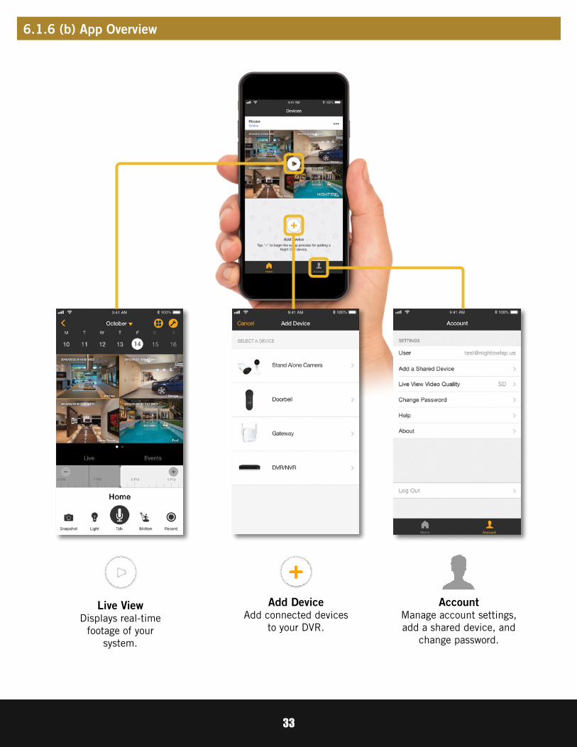
Account Manage account settings, add a shared device, and
change password.
Add Device Add connected devices
to your DVR.
Live ViewDisplays real-time
footage of yoursystem.
6.1.6 (b) App Overview

34
The Password Verification screen of the Startup Wizard will display your Admin password. Night Owl strongly recommends writing down your password within the Quick Setup Guide of your DVR.
The Camera/Channel Settings screen of the Startup Wizard serves as a reminder to mount your system’s cameras in the final position so you can make accurate adjustments to positioning, detection area and channel sensitivity.
6.1.7 Password Verification
6.1.8 Camera/Channel Settings
35
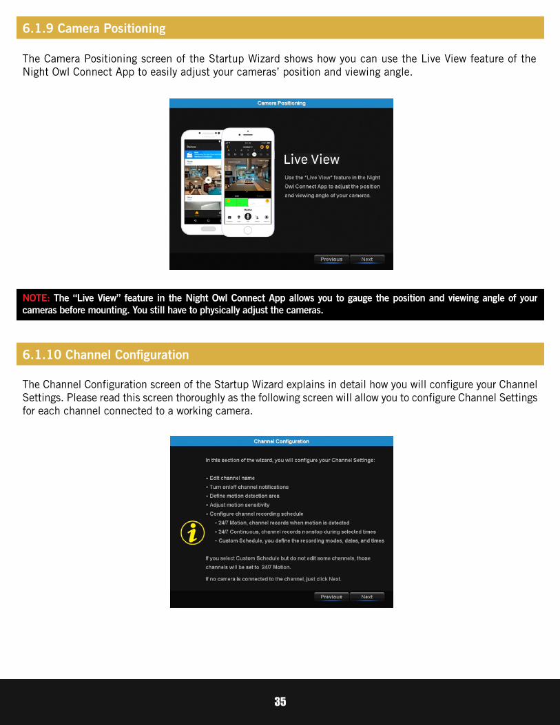
The Camera Positioning screen of the Startup Wizard shows how you can use the Live View feature of the Night Owl Connect App to easily adjust your cameras’ position and viewing angle.
The Channel Configuration screen of the Startup Wizard explains in detail how you will configure your Channel Settings. Please read this screen thoroughly as the following screen will allow you to configure Channel Settings for each channel connected to a working camera.
NOTE: The “Live View” feature in the Night Owl Connect App allows you to gauge the position and viewing angle of your cameras before mounting. You still have to physically adjust the cameras.
6.1.9 Camera Positioning
6.1.10 Channel Configuration

36
1
4
5
2
3
5b
5c
5a
Edit channel name.
Turn on/off alarm (push notifications).
Define motion detection area.
Configure channel recording schedule:
24/7 Motion – Channel records when motion is detected.
24/7 Continuous – Channel records non-stop during selected times.
Custom Schedule – You define the recording modes, dates and times.
1
4
5b
2
3
5a
5
5c
Adjust motion sensitivity.
The second Channel Configuration screen of the Startup Wizard allows you to configure the following channel settings:
NOTE: If you select Custom Schedule, but do not edit all active channels, the unedited channels will default to 24/7 recording.

37
The Default View screen of the Startup Wizard allows you to select the default view of the monitor connected to your DVR. You may select several viewing options from the drop-down menu:
1*1 channels on-screen.
2*2 channels on-screen.
3*3 channels on-screen.
8 channels on-screen (if applicable).
6.1.11 Default View

38
The Helpful Links and Support screen of the Startup Wizard contains QR codes linked to:
For more information, visit www.NightOwlSP.com and click the Support tab at the top of the page.
DVR Troubleshooting GuidePC/MAC® software download pageDVR Support pageRemote Viewing Support page
NOTE: Please scan these QR Codes directly from your TV/Monitor, NOT directly from this page.
Once you have successfully completed the Startup Wizard, click Finish to begin using your Night Owl DVR.
6.1.12 Helpful Links
6.1.13 Wizard Complete

39
6.2 Displays and Icons
The following sections will describe the main screens you will access for login, playback, recording and configuration.
Any time you want to configure or adjust your system settings you will be required to login by entering your user name and password. It’s important you save your login info or you won’t be able to access your DVR. Be sure to store your user name and password in a safe location. You will need this information to access the main menu.
User Name: Enter the Username you created in the Startup Wizard or User Menu.
Password: Enter the Password you created in the Startup Wizard or User Menu. If the password is incorrect you will be prompted to try again. Keep in mind the password is case sensitive between 6 and 20 characters.
Forgot PWD?: Sends a secure code to your recovery email. Once you input the secure code, you will be able to create a new password. Your DVR MUST be connected to the Internet to receive a secure code. If you do not have Internet connection, follow the instructions on your DVR to call Tech Support, an agent will assist you in creating a new password for you DVR.
6.2.1 Login Screen

40
Live View is the default screen you will see when viewing all channels on your DVR. You can customize the Live View by selecting Quad, Eight, or Nine channel configuration. In Quad and Nine view mode, double clicking on a channel will display the camera image in full screen; double click the full screen channel to revert to multiple channel view. In Eight view mode, double click on a channel to display in the larger screen within the Eight view screen; double clicking the larger screen turns that channel into full screen view. Double click again to revert to Eight view mode.
1
8
2 CAM01
3 4 5 6 79 10
1
2
3
4
5
6
7
10
9
8
Date and Time: Current date and time of the system.
Channel Name: On screen display of channel name.
DVR Status Recording Icon: Indicates that your DVR is currently recording video from this camera. This icon will be the same whether the recording was scheduled, initiated manually or triggered by motion.
Speaker Icon: Allows you to enable or disable audio streamed from an audio enabled camera.
Motion Detection Icon: Indicates that an alarm event such as motion detection, video loss or tampering has occurred.
Refresh Icon: Auto detection of camera formatting. By double clicking on this icon, you can change the format from CVI to AHD to TVI. This would allow the DVR to have different types of cameras connected at once. Question Mark: Shown when there is no signal to that particular channel.
Night Owl Logo: Indicates that the coaxial transmission protocols are operating.
Human Detection Icon: Indicates that an alarm event due to human activity has taken place.
Video Loss Icon: Indicates that the specific channel has lost the feed from the corresponding camera. This may be caused by a disconnected/damaged cable, the camera may have lost power or the camera may have been de-registered from the channel. This also appears if you do not have a camera connected to the channel.
6.2.2 Live View (All Channels)

41
1 2 3 4 5 6 7 8 9 10 11
1
2
3
4
5
6
7
8
10
11
9
Main Menu: Access the main menu to configure or adjust settings. Be sure to store your username and password in a safe location. You will need this information to access the main menu.
Lock Screen: Manually locks or unlocks screen. Once the screen is locked, you will need to enter your username and password to gain access.
Startup Wizard: Prompts the Startup Wizard to begin Startup Configuration.
Quad View: 4 channel viewing layout.
8-Channel View: 8 channel viewing layout.
9-Channel View: 9 channel viewing layout.
Auto Sequence: Start/Stop the slide show sequence of each channel.
Audio: Adjust the volume of the audio streaming from an audio enabled camera or audio input.
Playback: Access the recording/playback menu and functions.
Light: Manage individual light control settings for each camera.
PTZ: Open the Pan, Tilt, Zoom (PTZ) menu. This function will only work when a PTZ camera is connected to your DVR.
6.2.3 Right-Click Menu

42
For cameras with spotlights, use this sub menu to adjust the settings of the light.
On - All Bubble: Turns on the spotlight(s) for camera(s) with this feature that are connected to the DVR.
On - Ch.1 - Ch.8 Bubble(s): Activates the spotlight for the spotlight camera connected to the selected channel.
Off - All Bubble: Turns off the spotlight for all spotlight cameras connected to the DVR.
Off - Ch.1 - Ch.8 Bubble(s): Turns off the spotlight for the spotlight camera connected to the selected channel.
DelayTime: Determines the amount of time the spotlight will be on/active when manually turned on from the Light Menu.
Maximum DelayTime: The maximum DelayTime is 5 minutes, or 300 seconds.
Minimum DelayTime: The minimum DelayTime is 5 seconds.
6.2.3 (a) Light Menu
43
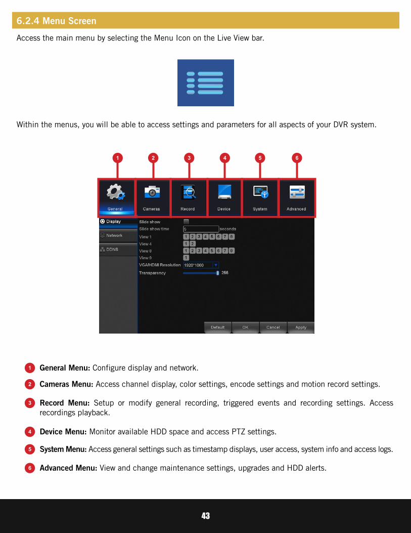
Access the main menu by selecting the Menu Icon on the Live View bar.
Within the menus, you will be able to access settings and parameters for all aspects of your DVR system.
1 2 3 4 5 6
1
2
3
5
6
4
General Menu: Configure display and network.
Cameras Menu: Access channel display, color settings, encode settings and motion record settings.
Record Menu: Setup or modify general recording, triggered events and recording settings. Access recordings playback.
System Menu: Access general settings such as timestamp displays, user access, system info and access logs.
Advanced Menu: View and change maintenance settings, upgrades and HDD alerts.
Device Menu: Monitor available HDD space and access PTZ settings.
6.2.4 Menu Screen
44
CHAPTER 7MENUS
AND SETTINGS
45
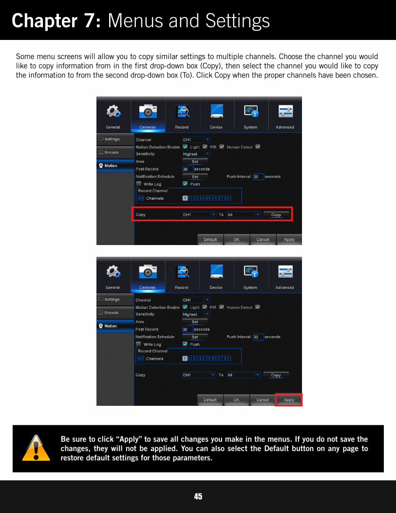
Some menu screens will allow you to copy similar settings to multiple channels. Choose the channel you would like to copy information from in the first drop-down box (Copy), then select the channel you would like to copy the information to from the second drop-down box (To). Click Copy when the proper channels have been chosen.
Chapter 7: Menus and Settings
Be sure to click “Apply” to save all changes you make in the menus. If you do not save the changes, they will not be applied. You can also select the Default button on any page to restore default settings for those parameters.
46
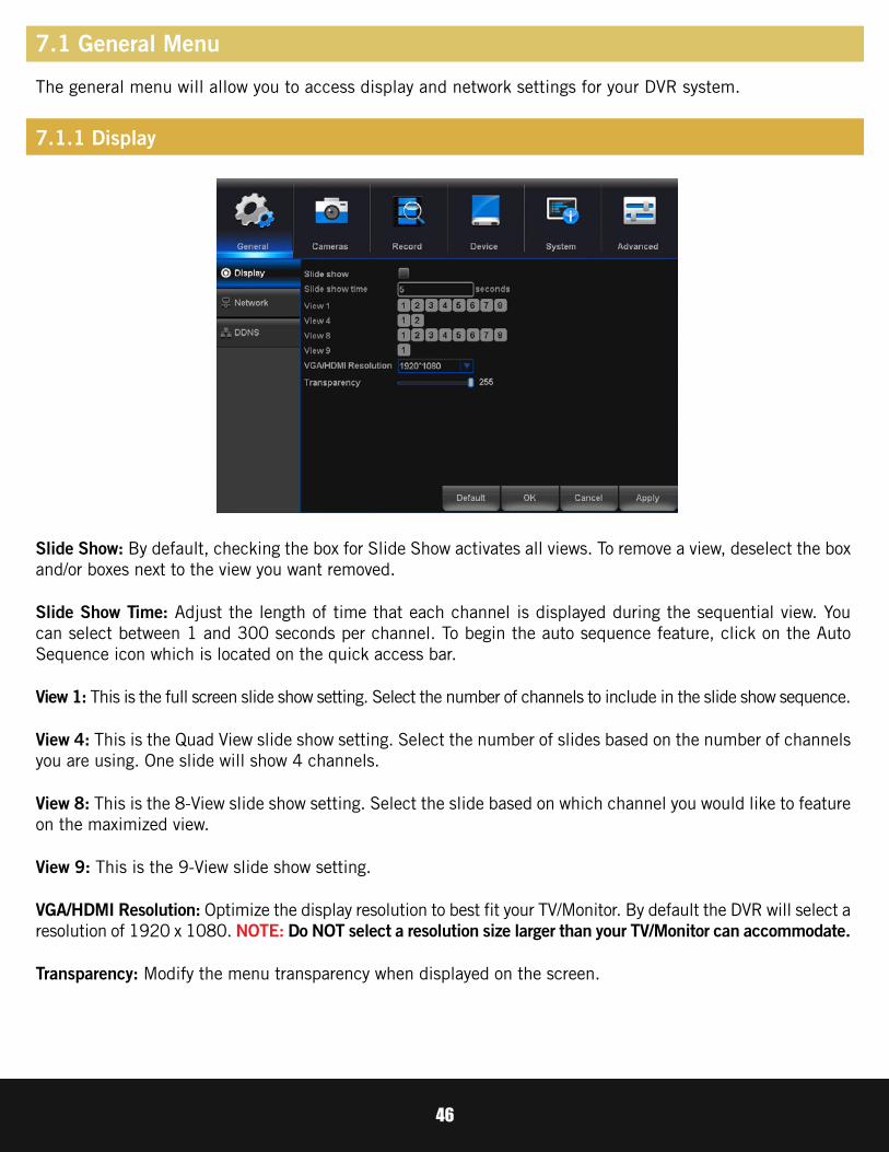
Slide Show: By default, checking the box for Slide Show activates all views. To remove a view, deselect the box and/or boxes next to the view you want removed.
Slide Show Time: Adjust the length of time that each channel is displayed during the sequential view. You can select between 1 and 300 seconds per channel. To begin the auto sequence feature, click on the Auto Sequence icon which is located on the quick access bar.
View 1: This is the full screen slide show setting. Select the number of channels to include in the slide show sequence.
View 4: This is the Quad View slide show setting. Select the number of slides based on the number of channels you are using. One slide will show 4 channels.
View 8: This is the 8-View slide show setting. Select the slide based on which channel you would like to feature on the maximized view.
View 9: This is the 9-View slide show setting.
VGA/HDMI Resolution: Optimize the display resolution to best fit your TV/Monitor. By default the DVR will select a resolution of 1920 x 1080. NOTE: Do NOT select a resolution size larger than your TV/Monitor can accommodate.
Transparency: Modify the menu transparency when displayed on the screen.
7.1 General Menu
The general menu will allow you to access display and network settings for your DVR system.
7.1.1 Display

47
Find network values and optimize connectivity based on your Internet connection. In most cases the values should populate automatically once your DVR is connected to your Modem/Router and Internet connection is established. The values in this section should only be adjusted if you are an advanced user and have extensive experience in device networking.
DHCP Enable: The most common network connection type. These values will be gathered automatically from your ISP when connected.
Static IP: Modify these values if you are using a static IP address. Information can be obtained from your router and ISP.
Web Port: Allows access to your DVR with your computer through your LAN or the Internet. In most cases the default value of 80 will provide the most optimal connectivity.
IP Address: Network address of the connected DVR.
Subnet Mask: The range of IP addresses that can be found in the network. This should always be set to the default address 255.255.255.000.
Gateway: The connection between two networks. This should always be the IP address of the connected router.
DNS1: Primary Domain Name System server address.
DNS2: Secondary Domain Name System server address.
7.1.2 Network ADVANCED

48
The DDNS option allows you to set up a free website address that will point back to the DVR regardless of whether the IP Address changes. If you do not have a static IP Address, you should use this option.
Please visit www.NightOwlDVR.com to register for your free domain name (DNS).
Enable: Allows you to enable or disable the use of DDNS protocol.
Server: When using the Night Owl free domain name server, you must configure this setting to NIGHTOWL.
Domain Name: Input the domain name you created by registering your DDNS at www.NightOwlDVR.com.
User Name: Input the UserID created during the DDNS registration.
Password: Input the password created during the DDNS registration.
7.1.3 DDNS

49
7.2 Cameras MenuAdjust or modify individual camera settings connected to your DVR.
Channel Title: Set display options for each channel.
Time Display: Time displayed on channel view.
Channel Title: Display channel name on channel view.
Record Status: Display record status on channel view.
Alarm Status: Display alarm status on channel view.
Bitrate Info: Display bitrate information on channel view.
Channel: Set the channel to edit.
Time Display Position and Channel Title Position: Check the boxes Display Time and Channel Title to view the time and channel title on channel view.
Color Setting: Click Set to access a sub-menu to adjust the colors of the selected channel. In this sub-menu, you can adjust the Hue, Brightness, Contrast, Grain, Horizontal Sharpness, Vertical Sharpness and Saturation of the image.
Region Cover: Enable or Disable privacy zones on the selected channel.
7.2.1 Settings
50
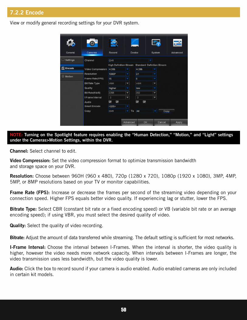
Channel: Select channel to edit.
Video Compression: Set the video compression format to optimize transmission bandwidth and storage space on your DVR.
Resolution: Choose between 960H (960 x 480), 720p (1280 x 720), 1080p (1920 x 1080), 3MP, 4MP, 5MP, or 8MP resolutions based on your TV or monitor capabilities.
Frame Rate (FPS): Increase or decrease the frames per second of the streaming video depending on your connection speed. Higher FPS equals better video quality. If experiencing lag or stutter, lower the FPS.
Bitrate Type: Select CBR (constant bit rate or a fixed encoding speed) or VB (variable bit rate or an average encoding speed); if using VBR, you must select the desired quality of video.
Quality: Select the quality of video recording.
Bitrate: Adjust the amount of data transferred while streaming. The default setting is sufficient for most networks.
Audio: Click the box to record sound if your camera is audio enabled. Audio enabled cameras are only included in certain kit models.
I-Frame Interval: Choose the interval between I-Frames. When the interval is shorter, the video quality is higher, however the video needs more network capacity. When intervals between I-Frames are longer, the video transmission uses less bandwidth, but the video quality is lower.
View or modify general recording settings for your DVR system.
7.2.2 Encode
NOTE: Turning on the Spotlight feature requires enabling the “Human Detection,” “Motion,” and “Light” settings under the Cameras>Motion Settings, within the DVR.

51
Motion Detection Enable: When checked, the motion detection feature will be enabled on the selected channel. By default all channels have motion detection enabled.
Sensitivity: Adjust the level of motion detection. A lower setting will require more movement in the camera range to begin recording.
Post Record: Set the amount of time to record after motion is detected (between 30 and 300 seconds). This feature also sets the amount of time the spotlight remains on after detecting motion.
Area: Clicking Set will allow you to configure areas which will and will not detect motion. Red boxes denote areas that will detect motion and uncolored boxes show areas that will not. When finished, right click to go back to menu.
Channel: Select the channel you want to configure.
Light: Toggle between ON and OFF to enable spotlight on the camera during motion detection.
PIR: Toggle between ON and OFF for passive infrared sensor (PIR) based motion detection.
Human Detection: Toggle between ON and OFF to enable human motion detection on the camera.
Notification Schedule: Set the push notification schedule.
7.2.3 Motion
52
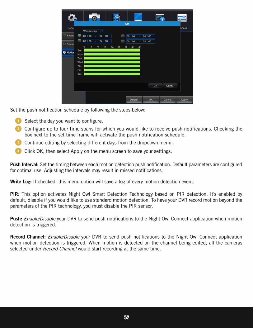
Set the push notification schedule by following the steps below:
Push Interval: Set the timing between each motion detection push notification. Default parameters are configured for optimal use. Adjusting the intervals may result in missed notifications.
Select the day you want to configure.
Configure up to four time spans for which you would like to receive push notifications. Checking the box next to the set time frame will activate the push notification schedule.
Continue editing by selecting different days from the dropdown menu.
Click OK, then select Apply on the menu screen to save your settings.
Write Log: If checked, this menu option will save a log of every motion detection event.
Push: Enable/Disable your DVR to send push notifications to the Night Owl Connect application when motion detection is triggered.
Record Channel: Enable/Disable your DVR to send push notifications to the Night Owl Connect application when motion detection is triggered. When motion is detected on the channel being edited, all the cameras selected under Record Channel would start recording at the same time.
PIR: This option activates Night Owl Smart Detection Technology based on PIR detection. It’s enabled by default, disable if you would like to use standard motion detection. To have your DVR record motion beyond the parameters of the PIR technology, you must disable the PIR sensor.
1
2
3
4
53
Night Owl’s Smart Detection Security System uses both motion sensors and infrared sensors to ensure the number of false alerts produced are minimal. Current motion detection technology allows your system to begin recording when a pixel change is detected by your unit. With the incorporation of infrared sensors, now your system must detect both a pixel change and a change in heat in order for your system to record when set to motion. Night Owl utilizes high tech UTC cabling which sends a signal from the camera to the DVR. If configured, the DVR will then send a push notification out to your Smart Device which will contain an embedded video clip of the object triggering the motion and infrared sensors.
In order to set the PIR Detection Area for your PIR camera, first log in to your DVR’s Main Menu then select Cameras > Motion. Choose the channel you want to configure from the drop down menu labeled Channel and then click the Area > Set button. You will be directed to the detection area screen. By default, all squares should be red, indicating the entire field of view is set to detect heat change.
If there is an area within the camera’s field of view that you do not want detection to be active, follow the steps below:
Click on a square in one corner of the area you don’t want to be detected.
Click and drag the mouse over the area you want to block.
Release the mouse and verify you have selected your desired area.
Right click the mouse and select Save to apply settings and exit the menu.
1
2
3
4
7.2.4 Setting Detection Area

54
Channel: Select the channel to edit recording settings.
Copy: Copy record settings to multiple channels.
Default: Revert to factory settings.
Max Pre-Record: Input the amount of time you would like the DVR to pre-record once an alarm has triggered recording. NOTE: You may choose between 0 and 30 seconds of pre-record. Keep in mind that this is an approximation.
Save: You must select save once a change has been made. If you do not select save, your changes will revert to previous settings.
Record Configuration: Click and drag to select the scheduled times of continuous and motion/alarm recording. Each square represents one hour of time within that day. Red squares indicate the DVR is set to Motion Record. Yellow squares represent the time in which the DVR will continuously record.
Video Length: Enter the duration of time to record when motion is detected, between 1 and 120 minutes. When using Continuous Recording, the video length will be the time scheduled.
7.3 Record MenuFrom this menu you can enable recording, set video settings and adjust streaming options.
7.3.1 Schedule
55
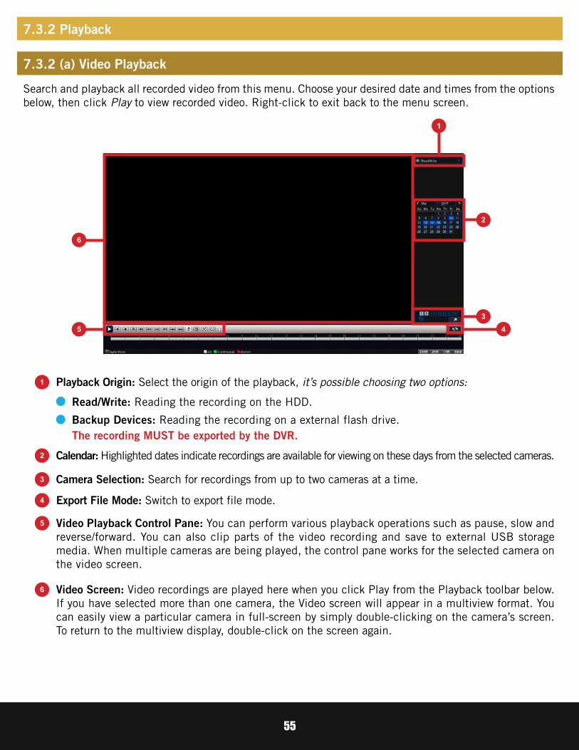
Search and playback all recorded video from this menu. Choose your desired date and times from the options below, then click Play to view recorded video. Right-click to exit back to the menu screen.
1
1
2
5
6
3
4
2
35
6
4
Playback Origin: Select the origin of the playback, it’s possible choosing two options:
Calendar: Highlighted dates indicate recordings are available for viewing on these days from the selected cameras.
Video Playback Control Pane: You can perform various playback operations such as pause, slow and reverse/forward. You can also clip parts of the video recording and save to external USB storage media. When multiple cameras are being played, the control pane works for the selected camera on the video screen.
Video Screen: Video recordings are played here when you click Play from the Playback toolbar below. If you have selected more than one camera, the Video screen will appear in a multiview format. You can easily view a particular camera in full-screen by simply double-clicking on the camera’s screen. To return to the multiview display, double-click on the screen again.
Camera Selection: Search for recordings from up to two cameras at a time.
Export File Mode: Switch to export file mode.
Read/Write: Reading the recording on the HDD.
Backup Devices: Reading the recording on a external flash drive.The recording MUST be exported by the DVR.
7.3.2 Playback
7.3.2 (a) Video Playback

56
Right-click within the Video Playback screen and the menu bar shown above will appear. This menu bar will allow you to go back, stop playing, and set to full screen.
7.3.2 (b) Right-Click Menu
57
9
10
11
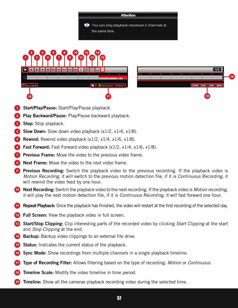
Previous Recording: Switch the playback video to the previous recording. If the playback video is Motion Recording, it will switch to the previous motion detection file, if it is Continuous Recording, it will rewind the video feed by one hour.
Next Recording: Switch the playback video to the next recording. If the playback video is Motion recording, it will play the next motion detection file, if it is Continuous Recording, it will fast forward one hour.
Repeat Playback: Once the playback has finished, the video will restart at the first recording of the selected day.
12
13
17
18
19
14
15
16
Full Screen: View the playback video in full screen.
Start/Stop Clipping: Clip interesting parts of the recorded video by clicking Start Clipping at the start and Stop Clipping at the end.
Type of Recording Filter: Allows filtering based on the type of recording: Motion or Continuous.
Timeline Scale: Modify the video timeline in time period.
Timeline: Show all the cameras playback recording video during the selected time.
Backup: Backup video clippings to an external file drive.
Status: Indicates the current status of the playback.
Sync Mode: Show recordings from multiple channels in a single playback timeline.
1
1
2
3
4
5
6
7
8
16
19
17 18
753 9 11 13 152 4 6 8 10 12 14
Start/Play/Pause: Start/Play/Pause playback.
Play Backward/Pause: Play/Pause backward playback.
Stop: Stop playback.
Slow Down: Slow down video playback (x1/2, x1/4, x1/8).
Rewind: Rewind video playback (x1/2, x1/4, x1/6, x1/8).
Fast Forward: Fast Forward video playback (x1/2, x1/4, x1/6, x1/8).
Previous Frame: Move the video to the previous video frame.
Next Frame: Move the video to the next video frame.

58
To export a Recording, once you have selected a specific date, switch to Export Recording Mode by clicking the Export File icon.
A list of all recordings will show in the navigation panel. You can play the video on the video screen before exporting. Play the video on the video screen, before exporting, by double clicking the video segment you want to watch.
After selecting the videos that you would like to export, click the Backup icon.
7.3.3 Exporting Recordings

59
The backup Dialog:
Format: Format the selected flash drive.
Burn: Start recording the live view video in the selected flash drive.
Backup: Export the recording videos.
Refresh: Will search for USB storage devices plugged into the DVR.
NOTE: This option will delete all data from your flash drive.

60
When “Backup” option is selected:
Recording: Recording Options: Motion Detection (MD), Manual, General, Alarm/MD, and All.
Channel: The channel to export recordings.
Start Time: Date/Time to start searching for recordings.
End Time: Date/Time to end the search for recordings.
Remove: Delete the recording from the search.
Add: Shows the recordings. Prompts the menu to display video recordings within the set search parameters.
Backup Format: The type of format used to backup your recordings. Standard format is MP4 and should be set to default. H26X should ONLY be selected if the firmware supports it. Please refer to system specifications.

61
Check available memory on your DVR HDD and set recording parameters to optimize storage.
Select: If multiple drives are installed, choose the HDD you would like to customize.
View Recording Times: Shows recordings that are on your HDD.
View Type and Capacity: Shows total storage being used and available space on your HDD. Also shows the type and status of recording. Also shows the type and status of the DVR’s HDD. If the status does not say Normal, please restart your DVR. If the status does not return to Normal after restarting, you may need to replace your HDD.
7.4 Device Menu
7.4.1 HDD

62
Configure settings on your DVR to control a PTZ enabled camera.
Channel: Choose the channel with a PTZ enabled camera. Not all cameras are PTZ enabled.
Address: Enter an ID number for the PTZ camera, greater than 0. If using multiple PTZ cameras, ID numbers cannot be the same.
Baudrate: Indicate the frequency of communication to the PTZ camera. We recommend leaving the default setting which is 9600.
DataBit: Select the amount of data to send during each transmission. 8 bits is standard for all modern data transmissions.
Parity: Detects corrupt commands sent to and from the PTZ camera. This should generally be left Disabled.
StopBit: Select the amount of extra data to send each time a direction is sent to the camera. The stopbit serves as a buffer between commands and should be 1 (by default) when utilizing Night Owl’s AHD PTZ camera.
Protocol: Is the type of PTZ data protocol that the DVR will use to control the PTZ cameras. The Default Value for Night Owl’s PTZ camera is PelcoD.
7.4.2 PTZ
7.4.2 (a) Using Control Method RS485
63
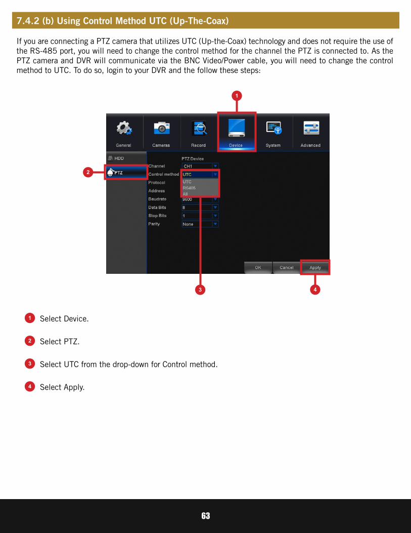
If you are connecting a PTZ camera that utilizes UTC (Up-the-Coax) technology and does not require the use of the RS-485 port, you will need to change the control method for the channel the PTZ is connected to. As the PTZ camera and DVR will communicate via the BNC Video/Power cable, you will need to change the control method to UTC. To do so, login to your DVR and the follow these steps:
Select Device.
Select PTZ.
Select Apply.
Select UTC from the drop-down for Control method.
2
1
3 4
1
2
4
3
7.4.2 (b) Using Control Method UTC (Up-The-Coax)

64
Set or adjust basic DVR settings such as the time, date and language.
Basic system configuration.
System Time: Manually set the date and time of your DVR.
Date Separator: Choose the format of date display.
Time Format: Select between a 12Hour or 24Hour display.
Language: Pick between ENGLISH, SPANISH or FRENCH language preferences.
Storage Full: Choose Overwrite if you would like your DVR to write over old recordings when the HDD is full. Choose Stop Record if you would like your DVR to stop recording when the HDD is full.
Video Format: NTSC or PAL formats are available to choose from. NTSC is the standard for video in North America and is the DVR’s default setting. Prior to changing the video format, make sure that your TV/Monitor is PALL compatible.
Menu Timeouts: Select the duration of time for an inactive menu to be displayed on-screen.
NTP: Select to change the NTP server.
Date Format: Choose the display format for the date. You can select Month/Day/Year, Year/Month/Day or Day/Month/Year.
7.5 System Menu
7.5.1 General

65
Configure Daylight Savings Time settings.
Configure National Time Protocol.
DST: Enable or Disable the Daylight Savings Time feature.Week Day - Date: Indicate whether you would like this feature to be applied the week of or an exact date.
Start Time: Select the date and time to apply the DST offset.End Time: Select the date and time to remove the DST offset.
Server Address: Select the server that the DVR will use.
7.5.1 (a) DST
7.5.1 (b) NTP

66
Create and modify user’s permissions.
Modify User: Select an existing user from the list to change the Username, Enable or Disable password access and modify permissions.
Modify Group: Select an existing group from the list to change the Group Name, Enable or Disable password access and modify permissions.
Modify PWD: Modify password.
Add User: Add a new user.
Delete User: Remove user.
Delete Group: Remove group.
Refresh: Restore User/Group settings to factory default.
Modify Email: Edit the email address used for password recovery.
Add Group: Add a new group.
7.5.2 Users

67
User Name: Create the new user’s User Name.
Password: Set the password for the new user.
Confirm Password: Re-input the set password for the new user.
Memo: Optional description of the new user account.
Group: Select a group to administer authority parameters.
Authority: Customize DVR authorities for the selected Group.
7.5.2 (a) Modify User

68
View your DVR system’s information and specifications at a glance. This menu will provide crucial device and network information to allow manual reconfiguration of your mobile application if needed. Keep in mind you can also scan the QR code on this screen using your Night Owl Connect App to quickly reconfigure your mobile device via our Owl Scan feature.
DISCLAIMER: The QR Code within this image is not active. Please use a QR Code Scanner on your Smart Device to scan the QR Code on your DVR’s menu screen.
Hardware Version: The current hardware version of your DVR.
Firmware Version: The current software version of you DVR.
Device Name: Product model number of your DVR.
UID: Your DVR’s unique identifier.
Model: Product model number of your DVR.
7.5.3 Info

69
Search for logs of all events and notifications on the DVR.
Type: Select the type of event log that you would like to Search for. Each choice corresponds to an action or event that was triggered and noted within the system. For example, System logs are recorded when the DVR time is synced with NTP (if enabled) or if the system is turned on or off.
Start Time: Choose the initial date of your log search period.
End Time: Choose the end date of your log search period.
Previous Page: Select to move backward through the search log.
Next Page: Select to move forward through the search log.
7.5.4 Log

70
Configure additional settings related to maintenance, hard drive space and upgrades.
Adjust settings related to default user access and reboot schedules.
Reboot: Set the frequency of reboots if this feature is enabled.
Auto Delete Old Files: Set whether you would like the DVR to automatically delete old files. This option is like the Overwrite option, however this allows you to customize the time period in which the HDD will automatically delete old recordings.
Load/Save: Load previously saved settings from a USB flash drive. Export logs and DVR configuration settings to a USB flash drive for future use.
Load Default: Revert to the standard reboot schedule.
Shutdown: Display the power menu (Shutdown, Reboot, Cancel).
7.6 Advanced Menu
7.6.1 Maintain

71
Within the Load Default menu, you may select which settings you would like to restore to default.
Configure notification settings for other triggered events not related to motion detection such as disk error, disk full or and/or video loss. These events will be added to the Alarm Status window.
7.6.2 Events

72
Net Disconnection: The DVR lost Internet connectivity.
IP Conflict: Another device is attempting to use the same IP Address of your DVR.
Illegal Login: Unauthorized access was attempted on your DVR.
Video Loss: The absence of video due to power loss disconnection.
Storage: No Space: This event setting allows you to set a percentage of available HDD space alarm so that when the available storage space is less than the percentage it is set to, the notification will appear on the Alarm Status window.
Storage Device Error: Refers to the status of the HDD and will notify you if it crashes or has become corrupt.
Event Type: Choose the type of event notification that you would like to appear on the Alarm Status window.
Enable: Select channel then turn notifications on or off for the selected Event type.
Show Message: Enable an icon to be displayed in Live View when the selected Event Type is triggered.
Buzzer: Turn an audible buzzer on for a duration of time to alert you when this Event Type happens. Deselect to disable this feature.
Push: select this option to send a notification to your Night Owl Connect App when this Event Type happens. NOTE: This option is not available for Event Types: Net Disconnected or IP Conflict.
No Storage: The HDD is full.
Auto Reboot: Enable or Disable the automatic reboot feature. NOTE: This is only available when Event Type or Storage Device Error is selected.
Less Than: Select the percentage of available HDD space to set the, Storage: No Space, Event Type notification. NOTE: This is only available for HDD space.

73
Index: Represents each camera.
Type of Alarms:
Notifications Check:
The Alarm Status notification message shows each camera’s alarm status. To prompt the Alarm Status message, you should enable the “Show Message” check mark on the Camera>Motion or the Advanced>Events menus. By default, this message is disabled.
Empty: No trigger detected.
Video Obstruction: Flags scenarios in which someone may cover the camera’s field of view or if they are attempting to tamper with the video signal.
Motion Detection: Video motion detection occurs when there is movement in front of your camera.
Video Loss: Video loss is regarded as an alarm event and occurs any time the DVR does not receive an active video signal on any of its inputs.
Green Check Mark: Unchecked alarm that already finished.
Red Check Mark: The alarm is happening.
7.6.3 Alarm Status

74
Advanced: Provides information about this window and allows you to adjust alarm notification settings.
OK: Hide the alarm status and verify that the alarm was noticed.
Red Check: The alarm is happening.
Green Check: Unchecked alarm that already finished.
Empty Box: No trigger detected.
0 Seconds: Clear alarm after 0 seconds.
5 Seconds: Clear alarm after 5 seconds.
30 Seconds: Clear alarm after 30 seconds.
5 minutes: Clear alarm after 5 minutes.
30 minutes: Clear alarm after 30 minutes.
After Confirmation: Clear alarm after confirmation.
Never: Never clear alarm.
Clear Alarm State In Time: 0 Seconds:

75
Control settings for auto upgrades of the DVR software.
Upgrade from USB: Upgrade the DVR firmware from a USB flash drive. To upgrade DVR firmware, insert a USB flash drive containing the DVR upgrade file into the USB port on the back of your DVR. Then select the correct file from the “Upgrade File” drop-down menu and select “Upgrade”.
Auto Upgrade: Enable or Disable the auto upgrade feature. Firmware updates will be detected automatically when this feature is enabled. The default selection for the auto upgrade feature is “enable”.
Check For Updates: Click on “Check” button to manually check for updated software versions. If an upgrade is detected, click “OK” button on the pop-up window to download and install the new version.
Camera Upgrade: To upgrade camera firmware, insert a USB flash drive containing the camera upgrade file into the USB port on the back of your DVR. Then select the correct file from the “Upgrade File” drop-down menu and select “Upgrade”.
7.6.4 Auto Upgrade

76
CHAPTER 8GLOSSARY

77
DDNS: Dynamic Domain Naming System. Method for automatically updating hostnames, address or other information like a URL on a given name server.
DHCP: Dynamic Host Configuration Protocol. A network protocol that allows a server to automatically assign a device and IP address.
IP: Internet Protocol. Protocol for standard communications across the Internet.
ISP: Internet Service Provider. An organization that provides services for accessing or using the Internet.
PIR: Passive Infrared. Heat-based sensors eliminate most false alarms and only delivers alerts when people, animals or vehicles are detected.
SMTP: Simple Mail Transfer Protocol. Standards used for email transmission.
UPS: Uninterrupted Power Supply. Device used to keep the DVR and cameras powered when the main power supply is lost or disconnected.
UTC (Up-the-Coax): This new technology allows for PTZ functions to be sent back and forth between the DVR and camera using a standard BNC (Video/Power) cable without the need for a separate port.
C20X and C50X: Hi-Definition Analog. Delivering crisp and clear HD images over coaxial cable.
Chapter 8: Glossary

78
CHAPTER 9WARRANTY
79
NIGHT OWL, LLC (“Night Owl”) provides the following warranty to the original retail purchaser only (the “Purchaser”) with respect to this product (the “Product”):
For a period of one (1) year after the date of sale, the Product shall be free from manufacturing defects in material and workmanship. In the event that the Product is defective, the Purchaser must return the Product at Purchaser’s cost with the original proof of purchase receipt. In its sole discretion, Night Owl will either repair or replace the Product at no additional cost to the Purchaser. Any replacement Product (or parts) will be covered by the same warranty as the original Product through the expiration date of the original warranty period.
Except as otherwise prohibited by law, this warranty is in lieu of other warranties, express or implied and Night Owl neither assumes no authorizes any person to assume for it any other obligation or liability in connection with the sale or service of the Product.
In no event shall Night Owl be liable for any special or consequential damages arising from the use of the Product or arising from the malfunctioning or non-functioning of the Product or for any delay in the performance of this warranty due to any cause beyond its control. This warranty shall not apply to installation or the removal and re-installation of products after repair.
Night Owl does not make any claims or warranties of any kind whatsoever regarding the Product’s potential, ability or effectiveness to prevent, minimize or in any way affect personal or property damage or injury. Night Owl is not responsible for any personal damage, loss or theft related to the Product or to its use for any harm, whether physical or mental related thereto. Any and all claims or statements, whether written or verbal, by salespeople, retailers, dealers or distributors to the contrary are not authorized by Night Owl and do not affect this provision of this warranty.
ExclusionsThis warranty does not apply to the following parts or upon the following events:
1. Bulbs, LEDS and batteries;2. The Product was not used or installed in the manner described in the installation instructions;3. Negligent use of the Product or misuse or abuse of the Product;4. Electrical short circuits or power surges;5. Use of replacement parts not supplied by Night Owl;6. Product is either tampered with, modified or repaired by another service provider;7. Product has not been maintained in accordance;8. Accident, fire, flood or other acts of God;9. Failure to use Night Owl approved accessories;10. Defects or damages arising by use of the Product in other than normal conditions (including
normal atmospheric, moisture and humidity conditions).
Chapter 9: Warranty

80
Returns Under This WarrantyIn order to obtain service, please make sure that you have registered your product on-line no later than thirty (30) days after purchase at www.NightOwlSP.com in the warranty registration section or in any other manner described in the instructions.
DisclaimerCertain uses, publication and/or distribution of video/audio recordings from security cameras and/or audio devices are prohibited or restricted by federal, state and local laws. When enabling and/or using audio recording features with your hidden security camera, be sure to comply with the laws in your country, state and locality.
Mac and Mac OS X are registered trademarks of Apple Inc. Windows, Windows XP, Windows Vista, Windows 7, Windows 8 and Windows 10 are registered trademarks of Microsoft Corporation in the United States and/or other countries.

81
CHAPTER 10TROUBLESHOOTING

82
If a problem occurs, you may be able to easily correct it yourself. The following table describes some common issues and their most likely solutions. Please refer to the table before calling technical support.
Chapter 10: Troubleshooting
Error Possible Causes Solutions
System is not receiving power or is not powering up.
Cable from power adapter is loose or is unplugged.
1. Confirm that all cables are connected correctly.
2. Confirm that the power adapter is securely connected to the back of the unit.
Cables are connected, but system is not receiving sufficient power.
1. Confirm that the system is powered ON (LED indicators on the front should be ON).
2. If the unit is connected through a power bar or surge protector, try bypassing the bar and connecting the power directly to the wall outlet.
3. Confirm that there is power at the outlet.
4. Connecting the power cable to another outlet.
5. Test the outlet with another plugged device (such as a phone charger).
Hard drive is full (0%) and the unit is no longer recording. Overwrite is not enabled.
Go to the Device Menu > HDD and ensure that Overwrite is set to Auto.
Mouse not detected by system.
Mouse cable is not firmly connected to the system. Firmly connect the mouse cable
to the USB Mouse port on the front panel.Mouse is not connected to the
system.
System needs to be reset.
Power off the system (disconnect power cable). Firmly connect a USB mouse to the USB Mouse port on the front panel of the system. Reconnect the power cable to the DC 19V port on the real panel.

83
Error Possible Causes Solutions
There is no picture on selected channels/camera picture is not being displayed.
Camera cables are loose or have become disconnected.
1. Check the camera video cable and connections.
2. Disconnect and reconnect the cable at the system and at the camera.
3. Try moving the camera to another channel or use another cable.
The image on the DVR appears, but does not have sound.
Audio cables are loose or have been disconnected.
Check the AUDIO connection to the DVR.
Audio channels are disabled.
Left click in Live View to bring up the Volume control and ensure that the channel(s) are not low or muted.
Volume on external speakers(not included) is low or off.
Increase volume on external speakers (not included).
A “whirring” noise is coming from the system. Fan is active. The noise means the exhaust
fan is working normally.The system beeps at startup. The beep at startup is normal.
The system beeps during motion detection.
Motion detection is enabled, but the alarm buzzer is activated.
Go to Right-Click Menu > Main Menu > Cameras > Motion > Select the Channel andun-check the Buzzer check box.

84
CHAPTER 11USER INFORMATION

85
Be sure to write down all the important information below and place it in a secure location.
Admin Password:
IP Address:
Web Port:
Subnet Mask:
Gateway:
DNS1:
DNS2:
User Password:
Model Number:
UID:
General DVR Information
Internet Login Information
NOTE: This information can be found within the General Menu tab under Network in your DVR’s Main Menu.
NOTE: This information can be found on page 67.
Chapter 11: User Information
86
Rev 190211
www.NightOwlSP.comiPhone, iPad, Mac and Mac OS X are registered trademarks of Apple Inc.Windows, Windows XP, Windows Vista, Windows 7, Windows 8 and Windows 10 are registered trademarks of Microsoft Corporation in the United States and/or other countries.
EMAILSales [email protected]
Technical [email protected]
PHONE (English, Spanish & French)
Sales / Technical Support1.866.390.1303Live Chat 24/7, 365 days a year
WEBSITE24/7 Product Support• How-To Videos• Manuals
CONTACT US
Need Help?
For system manuals, troubleshooting guides, FAQs, video tutorials and more:
Please refer to the sticker located on top of the device for steps on how to access your product’s support material.