Embed Size (px)
Citation preview
SHOP MANUALWEBMTNV000
DIESEL ENGINE
3D82AE SERIES
3D84E SERIES
3D88E SERIES
4D88E SERIES
4D98E SERIES
4D106 SERIES
S4D84E SERIES
S4D98E SERIES
S4D106 SERIES
SHOP MANUALWEBMTNV000
APPLICABLE MACHINE MODEL
ENGINE MODEL
PC27R-8 3TNV82A-M5FA 3D82AE-5MFAPC35R-8 3TNV88-N5FA 3D88E-5NFAPC45R-8 4TNV88-N5FA 4D88E-5NFAPC75R-2 4TNV98-X2FB 4D98E-2XFBPW75R-2 4TNV98-X2FB 4D98E-2XFBPC95R-2 4TNV106-S2FB 4D106-2SFBPW95R-2 4TNV106-S2FB 4D1062SFBPC110R-1 4TNV106T-W2FB S4D106-2WFBPW110R-1 4TNV106T-W2FB S4D106-2WFBSK510-5 3TNV84-K5FD 3D84E-5KFDSK714-5 4TNV88-K5FD 4D88E-5KFDSK815-5 4TNV88-K5FD 4D88E-5KFDSK815-5 turbo 4TNV84T-K5FD S4D84E-5KFDSK818-5 4TNV88-K5FD 4D88E-5KFDSK820-5 turbo 4TNV84T-K5FD S4D84E-5KFDSK1020-5 4TNV98-N2FE 4D98E-2NFESK1020-5 turbo 4TNV98T-N2FE S4D98E-2NFESK1026-5 turbo 4TNV98T-N2FE S4D98E-2NFEWB70A-1 4TNV98-N2FA 4D98E-2NFAWB98A-2 4TNV106T-S2FC S4D106-2SFCWB91R-2 4TNV106-S2FA 4D106-2SFAWB93R-2 4TNV106T-S2FA S4D106-2SFAWB97R-2 4TNV106T-S2FA S4D106-2SFAWB97S-2 4TNV106T-S2FA S4D106-2SFAWB150AWS-2 4TNV106T-S2FA S4D106-2SFA
YANMAR DESCRIPTION KOMATSU DESCRIPTION
PREFACE This manual describes the service procedures for the TNV series engines of indirect injection system that have been certified by the US EPA, California ARB and/or the 97/68/EC Directive for industrial use. Please use this manual for accurate, quick and safe servicing of the said engine. Since the explanation in this manual assumes the standard type engine, the specifications and components may partially be different from the engine installed on individual work equipment (power generator, pump, compressor, etc.). Please also refer to the service manual for each work equipment for details. The specifications and components may be subject to change for improvement of the engine quality without notice. If any modification of the contents described herein becomes necessary, it will be notified in the form of correction information each time.
SAFETY LABELS
Most accidents are caused by negligence of basic safety rules and precautions. For accident prevention, it is important to avoid such causes before development to accidents. Please read this manual carefully before starting repair or maintenance to fully understand safety precautions and appropriate inspection and maintenance procedures. Attempting at a repair or maintenance job without sufficient knowledge may cause an unexpected accident.
It is impossible to cover every possible danger in repair or maintenance in the manual. Sufficient consideration for safety is required in addition to the matters marked . Especially for safety precautions in a repair or maintenance job not described in this manual, receive instructions from a knowledgeable leader.
Safety marks used in this manual and their meanings are as follows:
DANGER-indicates an imminently hazardous situation, which, if not avoided, WILL result in death or serious injury.
WARNING-indicates a potentially hazardous situation, which, if not avoided, COULD result in death or serious injury.
CAUTION-indicates a potentially hazardous situation, which, if not avoided, MAY result in minor or moderate injury.
NOTICE-indicates that if not observed, the product performance or quality may not be guaranteed.
Safety Precautions
(1) SERVICE AREA
Sufficient Ventilation Inhalation of exhaust fumes and dust particles may be hazardous to ones health. Running engines welding, sanding, painting, and polishing tasks should be only done in well ventilated areas.
Safe / Adequate Work Area
The service area should be clean, spacious, level and free from holes in the floor, to prevent “slip” or “trip and fall” type accidents.
Bright, Safely Illuminated Area The work area should be well lit or illuminated in a safe manner. For work in enclosed or dark areas, a “drop cord” should be utilized. The drop cord must have a wire cage to prevent bulb breakage and possible ignition of flammable substances.
Safety Equipment Fire extinguisher(s), first aid kit and eye wash / shower station should be close at hand (or easily accessible) in case of an emergency.
(2) WORK – WEAR (GARMENTS
Safe Work Clothing Appropriate safety wear (gloves, special shoes/boots, eye/ear protection, head gear, harness’, clothing, etc.) should be used/worn to match the task at hand. Avoid wearing jewelry, unbuttoned cuffs, ties or loose fitting clothes around moving machinery. A serious accident may occur if caught in moving/rotating machinery.
(3) TOOLS
Appropriate Lifting / Holding
When lifting an engine, use only a lifting device (crane, jack, etc.) with sufficient lifting capacity. Do not overload the device. Use only a chain, cable, or lifting strap as an attaching device. Do not use rope, serious injury may result. To hold or support an engine, secure the engine to a support stand, test bed or test cart designed to carry the weight of the engine. Do not overload this device, serious injury may result. Never run an engine without being properly secured to an engine support stand, test bed or test cart, serious injury may result.
Appropriate Tools Always use tools that are designed for the task at hand. Incorrect usage of tools may result in damage to the engine and or serious personal injury.
(4) GENUINE PARTS and MATERIALS
Genuine Parts Always use genuine parts or recommended parts and goods. Damage to the engine, shortened engine life and or personal injury may result.
(5) FASTENER TORQUE
(
(
Torqueing Fasteners Always follow the torque values and procedures as designated in the service manual. Incorrect values, procedures and or tools may cause damage to the engine and or personal injury.
6) Electrical
Short Circuits Always disconnect the (-) Negative battery cable before working on the electrical system. An accidental “short circuit” may cause damage, fire and or personal injury. Remember to connect the (-) Negative battery cable (back onto the battery) last. Fasten the terminals tightly.
Charging BatteriesCharging wet celled batteries produces hydrogen gas. Hydrogen gas is extremely explosive. Keep sparks, open flame and any other form of ignition away. Explosion may occur causing severe personal injury.
Battery Electrolyte Batteries contain sulfuric acid. Do NOT allow it to come in contact with clothing, skin and or eyes, severe burns will result.
7) WASTE MANAGEMENT
Observe the following instructions with regard to hazardous waste disposal. Negligence of these will have a serious impact on environmental pollution concerns. 1)
2)
3)
Waste fluids such as lube oil, fuel and coolant shall be carefully put into separate sealed containers and disposed of properly. Do NOT dispose of waste materials irresponsibly by dumping them into the sewer, overland or into natural waterways. Waste materials such as oil, fuel, coolant, solvents, filter elements and batteries, must be disposed of properly according to local ordinances. Consult the local authorities or reclamation facility.
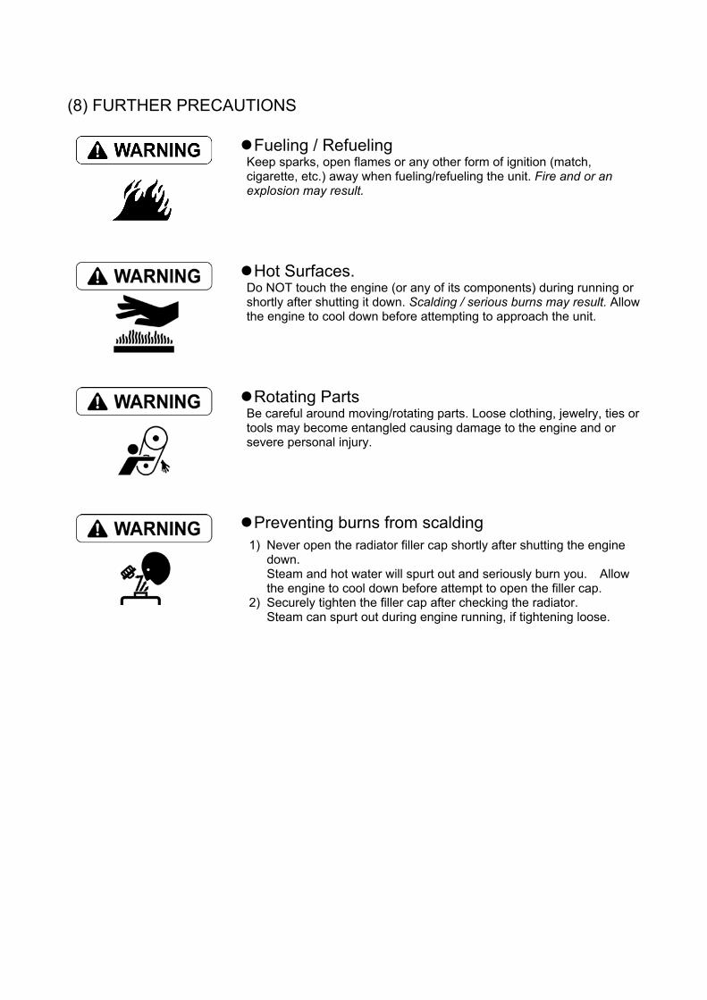
(8) FURTHER PRECAUTIONS Fueling / Refueling
Keep sparks, open flames or any other form of ignition (match, cigarette, etc.) away when fueling/refueling the unit. Fire and or an explosion may result.
Hot Surfaces. Do NOT touch the engine (or any of its components) during running or shortly after shutting it down. Scalding / serious burns may result. Allow the engine to cool down before attempting to approach the unit.
Rotating Parts Be careful around moving/rotating parts. Loose clothing, jewelry, ties or tools may become entangled causing damage to the engine and or severe personal injury.
Preventing burns from scalding 1)
2)
Never open the radiator filler cap shortly after shutting the engine down. Steam and hot water will spurt out and seriously burn you. Allow the engine to cool down before attempt to open the filler cap. Securely tighten the filler cap after checking the radiator. Steam can spurt out during engine running, if tightening loose.
Precautions for Service Work (1) Precautions for Safety Read the safety precautions given at the beginning of this manual carefully and always mind safety in work.
(2) Preparation for Service Work Preparation is necessary for accurate, efficient service work. Check the customer ledger file for the history of the engine. Preceding service date Period/operation hours after preceding service Problems and actions in preceding service Replacement parts expected to be required for service Recording form/check sheet required for service
(3) Preparation before Disassembly Prepare general tools, special service tools, measuring instruments, oil, grease, non-reusable parts, and parts expected to be required for replacement. When disassembling complicated portions, put match-marks and other marks at places not adversely affecting the function for easy reassembly.
(4) Precautions in Disassembly Each time a parts is removed, check the part installed state, deformation, damage, roughening, surface defect, etc. Arrange the removed parts orderly with clear distinction between those to be replaced and those to be used again. Parts to be used again shall be washed and cleaned sufficiently. Select especially clean locations and use clean tools for disassembly of hydraulic units such as the fuel injection pump.
(5) Precautions for Inspection and Measurement Inspect and measure parts to be used again as required to determine whether they are reusable or not.
(6) Precautions for Reassembly Reassemble correct parts in correct order according to the specified standards (tightening torques, and adjustment standards). Apply oil important bolts and nuts before tightening when specified. Always use genuine parts for replacement. Always use new oil seals, O-rings, packing and cotter pins. Apply sealant to packing depending on the place where they are used. Apply of grease to sliding contact portions, and apply grease to oil seal lips.
(7) Precautions for Adjustment and Check Use measuring instruments for adjustment to the specified service standards. How to Read this Manual (1) Range of Operation Explanation This manual explains the troubleshooting, installation/removal, replacement, disassemble/reassembly, inspection, adjustment and adjusting operation procedures for the TNV series engines with direct injection system. Refer to the manufacturer’s manual for each of the fuel injection pump, governor, starting motor and alternator except for their installation.
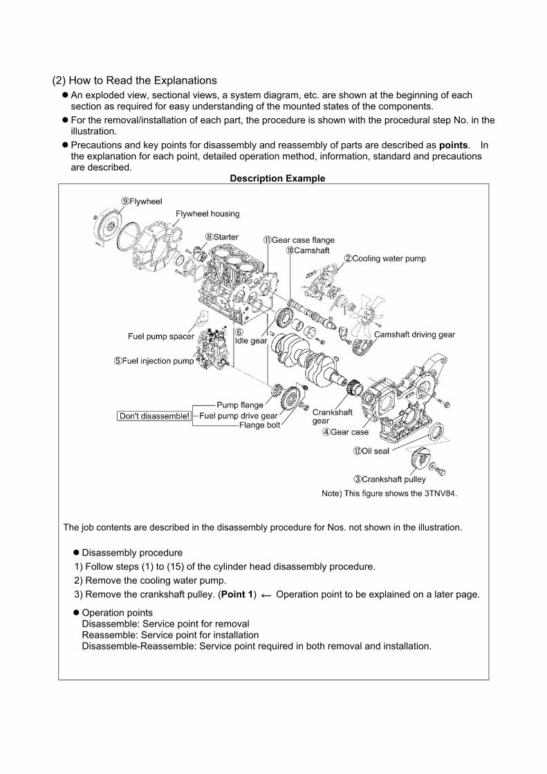
(2) How to Read the Explanations An exploded view, sectional views, a system diagram, etc. are shown at the beginning of each section as required for easy understanding of the mounted states of the components. For the removal/installation of each part, the procedure is shown with the procedural step No. in the illustration. Precautions and key points for disassembly and reassembly of parts are described as points. In the explanation for each point, detailed operation method, information, standard and precautions are described.
Description Example
The job contents are described in the disassembly procedure for Nos. not shown in the illustration. Disassembly procedure
1) Follow steps (1) to (15) of the cylinder head disassembly procedure. 2) Remove the cooling water pump. 3) Remove the crankshaft pulley. (Point 1) Operation point to be explained on a later page.
Operation points Disassemble: Service point for removal Reassemble: Service point for installation Disassemble-Reassemble: Service point required in both removal and installation.
Contents omitted in this manual Though the following jobs are omitted in the explanation in this manual, they should be conducted in actual work: 3) 4) 5)
Jacking up and lifting Cleaning and washing of removed parts as required Visual inspection
(3) Definition of Terms [NOTICE]: Instruction whose negligence is very likely to cause an accident. Always observe it. Standard: Allowable range for inspection and adjustment. Limit: The maximum or minimum value that must be satisfied during inspection or adjustment.
(4) Abbreviations
Abbreviation Meaning Abbreviation Meaning Assy assembly T.D.C. top dead center
Sub-Assy sub-assembly B.D.C. bottom dead center
a.T.D.C after top dead center OS oversize
b.T.D.C before top dead center US undersize
STD Standard Min-1 revolutions per minute
IN Intake PS Output (metric horsepower)
EX Exhaust T Bolt/nut tightening torque
CONTENTS
1. General ....................................................................................................... 1 1.1 Engine Nomenclature .............................................................................................................. 1 1.2 Specifications........................................................................................................................... 1 1.3 Fuel Oil, Lubricating Oil and Cooling Water........................................................................... 14
1.3.1 Fuel oil....................................................................................................................................14 1.3.2 Lubricating oil .........................................................................................................................15 1.3.3 Cooling water .........................................................................................................................15
1.4 Engine External Views........................................................................................................... 16 1.5 Structural Description............................................................................................................. 17 1.6 Exhaust gas emission regulation........................................................................................... 18
1.6.1 The Emission Standard in USA ..............................................................................................18 1.6.2 Engine identification ...............................................................................................................19 1.6.3 Guarantee Conditions for the EPA Emission Standard...........................................................20
2. Inspection and Adjustment........................................................................ 22 2.1 Periodic Maintenance Schedule ............................................................................................ 22 2.2 Periodic Inspection and Maintenance Procedure .................................................................. 23
2.2.1 Check before Daily Operation ................................................................................................23 2.2.2 inspection after initial 50 hours operation ...............................................................................25 2.2.3 Inspection every 50 hours ......................................................................................................28 2.2.4 Inspection every 250 hours or 3 months ................................................................................32 2.2.5 Inspection every 500 hours or 6 months ................................................................................35 2.2.6 Inspection every 1,000 hours or one year ..............................................................................37 2.2.7 Inspection every 2000 hours or 2 years .................................................................................46
2.3 Adjusting the no-load maximum or minimum speed.............................................................. 49 2.4 Sensor Inspection.................................................................................................................. 50
2.4.1 Oil pressure switch .................................................................................................................50 2.4.2 Thermo switch ........................................................................................................................50
2.5 Water leak check in cooling water system............................................................................. 50 2.6 Radiator cap inspection ......................................................................................................... 51 2.7 Thermostat Inspection ........................................................................................................... 51 2.8 Adjusting Operation ............................................................................................................... 52 2.9 Long storage.......................................................................................................................... 52
3. TROUBLESHOOTING.............................................................................. 53 3.1 Preparation before troubleshooting ....................................................................................... 53 3.2 Quick Reference Table for Troubleshooting .......................................................................... 54 3.3 Troubleshooting by measuring Compression Pressure......................................................... 57
4. Disassembly, Inspection and Reassembly of Engines.............................. 59 4.1 Complete disassembly and reassembly ................................................................................ 59
4.1.1 Introduction ............................................................................................................................59 4.1.2 Special service tools...............................................................................................................60 4.1.3 Complete disassembly ...........................................................................................................65 4.1.4 Precautions before and during reassembly ............................................................................69 4.1.5 Adjusting operation.................................................................................................................69
4.2 Cylinder Head: Disassembly, Inspection and Reassembly.................................................... 70 4.2.1 Components (2-valve cylinder head)......................................................................................70 4.2.2 Disassembly procedure:.........................................................................................................70 4.2.3 Reassembly procedure: .........................................................................................................71 4.2.4 Servicing points ......................................................................................................................72 4.2.5 Parts Inspection and measurement........................................................................................76 4.2.6 Valve seat correction ..............................................................................................................80 4.2.7 Valve guide replacement ........................................................................................................81 4.2.8 Valve stem seal replacement..................................................................................................82
4.3 Gear Train and Camshaft ...................................................................................................... 83 4.3.1 Components ...........................................................................................................................83 4.3.2 Disassembly procedure:.........................................................................................................83 4.3.3 Reassembly procedure: .........................................................................................................83 4.3.4 Servicing points ......................................................................................................................84 4.3.5 Parts inspection and measurement ........................................................................................87 4.3.6 Oil seal replacement (Gear case side) ...................................................................................89 4.3.7 Camshaft bushing replacement..............................................................................................89
4.4 Cylinder Block........................................................................................................................ 90 4.4.1 Components ...........................................................................................................................90 4.4.2 Disassembly procedure:.........................................................................................................90 4.4.3 Reassembly procedure: .........................................................................................................90 4.4.4 Servicing points ......................................................................................................................91 4.4.5 Parts inspection and measurement ........................................................................................95 4.4.6 Cylinder bore correction .......................................................................................................106 4.4.7 Piston pin bushing replacement ...........................................................................................107 4.4.8 Oil seal replacement (Flywheel housing side) ......................................................................107
5. LUBRICATION SYSTEM ........................................................................ 108 5.1 Lubrication System Diagram ............................................................................................... 108 5.2 Trochoid Pump Components ............................................................................................... 109 5.3 Disassembly(Reverse the procedure below for assembly) ................................................. 109 5.4 Servicing Points................................................................................................................... 109 5.5 Parts Inspection and Measurement......................................................................................110
5.5.1 Trochoid pump inspection and measurement.......................................................................110
6. COOLING SYSTEM.................................................................................112 6.1 Cooling Water System..........................................................................................................112 6.2 Cooling Water Pump Components .......................................................................................112 6.3 Disassembly (Reverse the procedure below for assembly) .................................................113 6.4 Servicing Points....................................................................................................................113
7. FUEL INJECTION PUMP/GOVERNOR...................................................114 7.1 Introduction ...........................................................................................................................114 7.2 Fuel Injection Pump..............................................................................................................114
7.2.1 Fuel system diagram ............................................................................................................114 7.2.2 External view and components.............................................................................................115 7.2.3 Disassembly procedure:.......................................................................................................115 7.2.4 Assembly procedure.............................................................................................................116 7.2.5 Servicing points ....................................................................................................................116
8. TURBOCHAGER: Disassembly, inspection and reassembly.....................118 8.1 Structure and Functions........................................................................................................118
8.1.1 Main specifications ...............................................................................................................118 8.1.2 Construction .........................................................................................................................118 8.1.3 Structural and functional outline ...........................................................................................119 8.1.4 Components .........................................................................................................................120
8.2 Service Standards and Tightening Torque........................................................................... 121 8.2.1 Service standards.................................................................................................................121 8.2.2 Tightening torque..................................................................................................................122
8.3 Periodic Inspection Procedure............................................................................................. 123 8.3.1 Periodic inspection intervals .................................................................................................123 8.3.2 Inspection procedure............................................................................................................124 8.3.3 Waste gate valve adjustment procedure ..............................................................................125
8.4 Disassembly Procedure....................................................................................................... 127 8.4.1 Preparation for disassembly .................................................................................................127 8.4.2 Inspection before disassembly .............................................................................................128 8.4.3 Disassembly .........................................................................................................................128
8.5 Washing and Inspection procedure ..................................................................................... 130 8.5.1 Washing ...............................................................................................................................130 8.5.2 Inspection procedure............................................................................................................131
8.6 Reassembly Procedure ....................................................................................................... 134 8.6.1 Preparation for reassembly...................................................................................................134 8.6.2 Reassembly .........................................................................................................................134
8.7 Handling after Disassembly and Reassembly ..................................................................... 137 8.7.1 Instructions for turbocharger installation...............................................................................137
8.8 Troubleshooting ................................................................................................................... 138 8.8.1 Excessively exhaust smoke .................................................................................................138 8.8.2 White smoke generation.......................................................................................................138 8.8.3 Sudden oil decrease.............................................................................................................139 8.8.4 Decrease in output ...............................................................................................................139 8.8.5 Poor (slow) response (starting) of turbocharger ...................................................................139 8.8.6 Abnormal sound or vibration.................................................................................................139
9. STARTING MOTOR................................................................................ 140 9.1 For 4TNV94L/ 98 ................................................................................................................. 140
9.1.1 Specifications .......................................................................................................................140 9.1.2 Components .........................................................................................................................141 9.1.3 Troubleshooting....................................................................................................................142 9.1.4 Names of parts and disassembly procedure ........................................................................143 9.1.5 Inspection and Maintenance ................................................................................................147 9.1.6 Service standards.................................................................................................................152 9.1.7 Assembly..............................................................................................................................153 9.1.8 Characteristic test.................................................................................................................155
9.2 For 4TNV106(T) .................................................................................................................. 156 9.2.1 Specifications .......................................................................................................................156 9.2.2 Congiguration drawing .........................................................................................................156 9.2.3 Troubleshooting ....................................................................................................................157 9.2.4 Component names and disassembly procedure ..................................................................158 9.2.5 Disassembly procedure........................................................................................................159 9.2.6 Inspection and maintenance ................................................................................................167 9.2.7 Assembly..............................................................................................................................173 9.2.8 Adjustment ...........................................................................................................................174 9.2.9 Service standards.................................................................................................................175
10. ALTERNATOR....................................................................................... 176 10.1 The 40A Alternator for 3TNV84 and other models............................................................. 176
10.1.1 Components .......................................................................................................................176 10.1.2 Specifications .....................................................................................................................177 10.1.3 Wiring diagram ...................................................................................................................177 10.1.4 Standard output characteristics ..........................................................................................178 10.1.5 Inspection...........................................................................................................................178
10.2 Troubleshooting ................................................................................................................. 179
11. ELECTRIC WIRING .............................................................................. 180 11.1 Electric Wiring Diagram ..................................................................................................... 180 11.2 PRECAUTION ON ELECTRIC WIRING............................................................................ 181
11.2.1 Alternator ............................................................................................................................181 11.2.2 Starter .................................................................................................................................182 11.2.3 Current limiter .....................................................................................................................183 11.2.4 Section area and resistance of electric wire .......................................................................184
12. SERVICE STANDARDS ....................................................................... 185 12.1 Engine Tuning.................................................................................................................... 185 12.2 Engine Body ...................................................................................................................... 186
12.2.1 Cylinder head .....................................................................................................................186 12.2.2 Gear train and camshaft .....................................................................................................189 12.2.3 Cylinder block.....................................................................................................................190
12.3 Lubricating Oil System (Trochoid Pump) ........................................................................... 195 12.3.1 Outside clearance of outer rotor .........................................................................................195 12.3.2 Side clearance of outer rotor ..............................................................................................195 12.3.3 Inside clearance of inner rotor ............................................................................................195 12.3.4 Rotor shaft clearance .........................................................................................................195
13. TIGHTENING TORQUE for BOLTS and NUTS .................................... 196 13.1 Tightening Torques for Main Bolts and Nuts ...................................................................... 196 13.2 Tightening Torques for Standard Bolts and Nuts ............................................................... 197
1. General
1. General
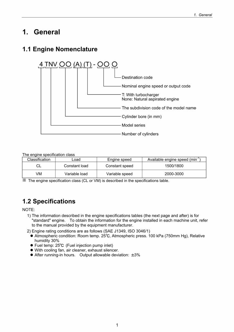
1.1 Engine Nomenclature
The engine specification class Classification Load Engine speed Available engine speed (min-1)
CL Constant load Constant speed 1500/1800
VM Variable load Variable speed 2000-3000
The engine specification class (CL or VM) is described in the specifications table.
1.2 Specifications NOTE:
1) The information described in the engine specifications tables (the next page and after) is for "standard" engine. To obtain the information for the engine installed in each machine unit, refer to the manual provided by the equipment manufacturer.
2) Engine rating conditions are as follows (SAE J1349, ISO 3046/1) Atmospheric condition: Room temp. 25 , Atmospheric press. 100 kPa (750mm Hg), Relative humidity 30% Fuel temp: 25 (Fuel injection pump inlet) With cooling fan, air cleaner, exhaust silencer. After running-in hours. Output allowable deviation: 3%
1
1. General
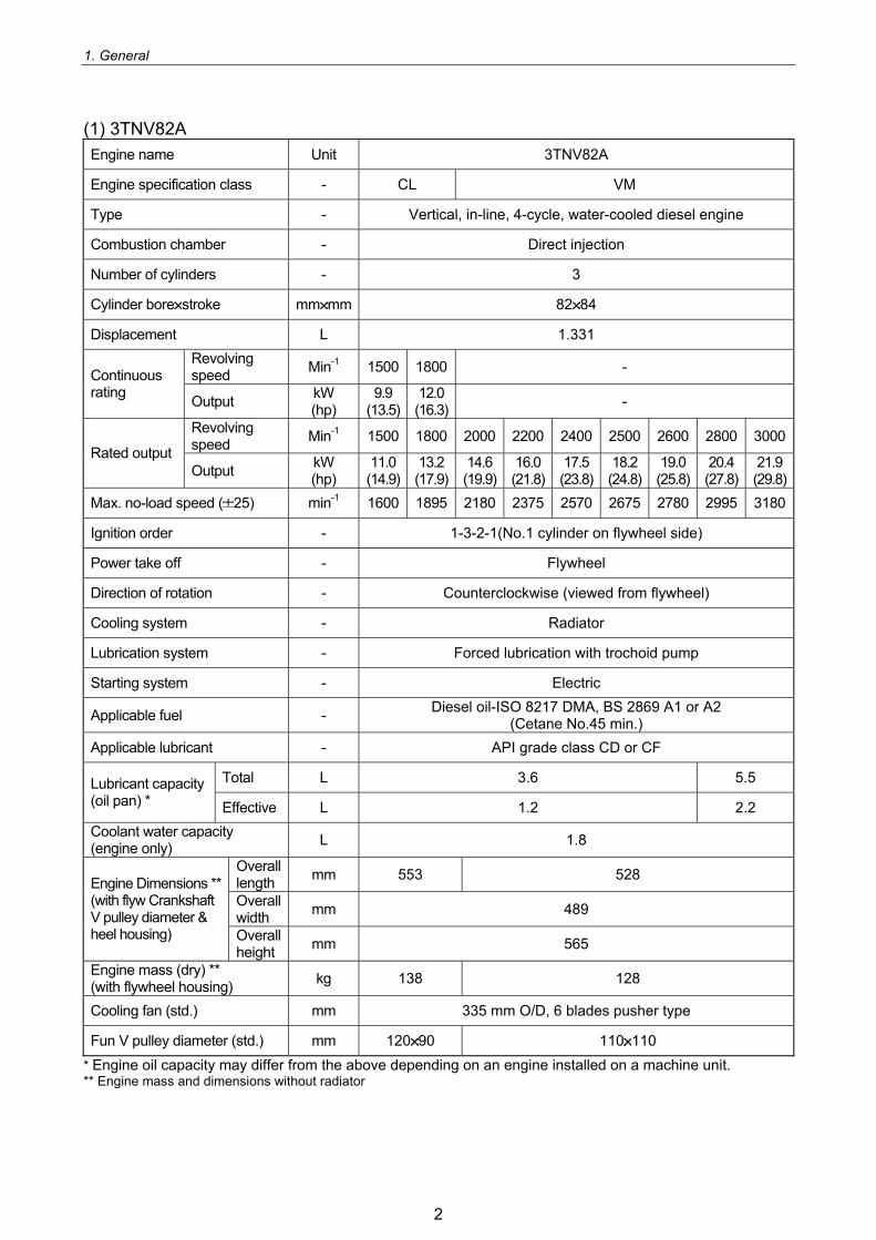
(1) 3TNV82A Engine name Unit 3TNV82A
Engine specification class - CL VM
Type - Vertical, in-line, 4-cycle, water-cooled diesel engine
Combustion chamber - Direct injection
Number of cylinders - 3
Cylinder bore stroke mm mm 82 84
Displacement L 1.331 Revolving speed Min-1 1500 1800 - Continuous
rating Output kW (hp)
9.9 (13.5)
12.0(16.3) -
Revolving speed Min-1 1500 1800 2000 2200 2400 2500 2600 2800 3000
Rated output Output kW
(hp) 11.0(14.9)
13.2(17.9)
14.6(19.9)
16.0(21.8)
17.5(23.8)
18.2 (24.8)
19.0 (25.8)
20.4(27.8)
21.9(29.8)
Max. no-load speed ( 25) min-1 1600 1895 2180 2375 2570 2675 2780 2995 3180
Ignition order - 1-3-2-1(No.1 cylinder on flywheel side)
Power take off - Flywheel
Direction of rotation - Counterclockwise (viewed from flywheel)
Cooling system - Radiator
Lubrication system - Forced lubrication with trochoid pump
Starting system - Electric
Applicable fuel - Diesel oil-ISO 8217 DMA, BS 2869 A1 or A2 (Cetane No.45 min.)
Applicable lubricant - API grade class CD or CF
Total L 3.6 5.5 Lubricant capacity (oil pan) * Effective L 1.2 2.2 Coolant water capacity (engine only) L 1.8
Overall length mm 553 528
Overall width mm 489
Engine Dimensions ** (with flyw Crankshaft V pulley diameter & heel housing) Overall
height mm 565
Engine mass (dry) ** (with flywheel housing) kg 138 128
Cooling fan (std.) mm 335 mm O/D, 6 blades pusher type
Fun V pulley diameter (std.) mm 120 90 110 110 * Engine oil capacity may differ from the above depending on an engine installed on a machine unit. **
Engine mass and dimensions without radiator
2
1. General
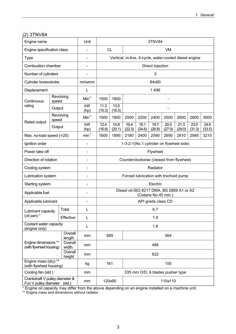
(2) 3TNV84 Engine name Unit 3TNV84
Engine specification class - CL VM
Type - Vertical, in-line, 4-cycle, water-cooled diesel engine
Combustion chamber - Direct injection
Number of cylinders - 3
Cylinder bore stroke mm mm 84 90
Displacement L 1.496 Revolving speed Min-1 1500 1800 - Continuous
rating Output kW (hp)
11.3(15.3)
13.5(18.3) -
Revolving speed Min-1 1500 1800 2000 2200 2400 2500 2600 2800 3000
Rated output Output kW
(hp) 12.4(16.8)
14.8(20.1)
16.4(22.3)
18.1(24.6)
19.7(26.8)
20.5 (27.9)
21.3 (29.0)
23.0(31.3)
24.6(33.5)
Max. no-load speed ( 25) min-1 1600 1895 2180 2400 2590 2690 2810 2995 3210
Ignition order - 1-3-2-1(No.1 cylinder on flywheel side)
Power take off - Flywheel
Direction of rotation - Counterclockwise (viewed from flywheel)
Cooling system - Radiator
Lubrication system - Forced lubrication with trochoid pump
Starting system - Electric
Applicable fuel - Diesel oil-ISO 8217 DMA, BS 2869 A1 or A2 (Cetane No.45 min.)
Applicable lubricant - API grade class CD
Total L 6.7 Lubricant capacity (oil pan) * Effective L 1.9 Coolant water capacity (engine only) L 1.8
Overall length mm 589 564
Overall width mm 486 Engine dimensions **
(with flywheel housing) Overall height mm 622
Engine mass (dry) ** (with flywheel housing) kg 161 155
Cooling fan (std.) mm 335 mm O/D, 6 blades pusher type Crankshaft V pulley diameter & Fun V pulley diameter (std.) mm 120 90 110 110
* Engine oil capacity may differ from the above depending on an engine installed on a machine unit. **
Engine mass and dimensions without radiator
3
1. General
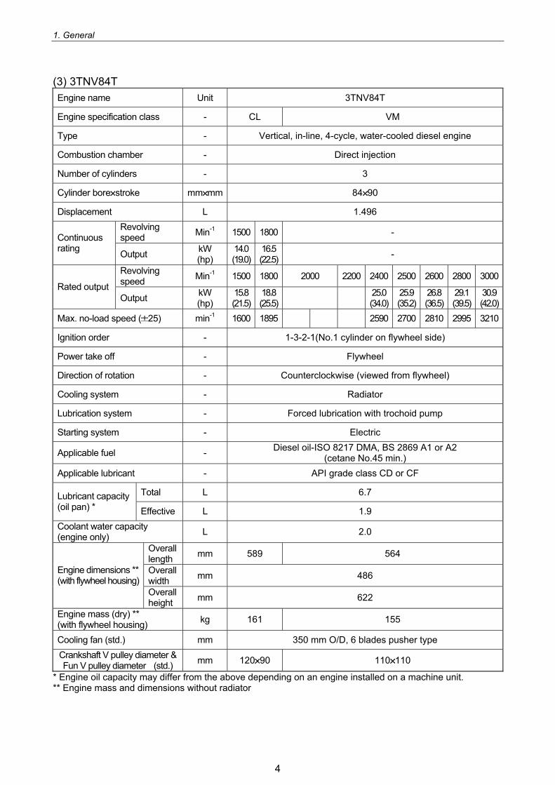
(3) 3TNV84T Engine name Unit 3TNV84T
Engine specification class - CL VM
Type - Vertical, in-line, 4-cycle, water-cooled diesel engine
Combustion chamber - Direct injection
Number of cylinders - 3
Cylinder bore stroke mm mm 84 90
Displacement L 1.496 Revolving speed Min-1 1500 1800 - Continuous
rating Output kW (hp)
14.0 (19.0)
16.5 (22.5) -
Revolving speed Min-1 1500 1800 2000 2200 2400 2500 2600 2800 3000
Rated output Output kW
(hp) 15.8 (21.5)
18.8 (25.5)
25.0 (34.0)
25.9 (35.2)
26.8 (36.5)
29.1 (39.5)
30.9 (42.0)
Max. no-load speed ( 25) min-1 1600 1895 2590 2700 2810 2995 3210
Ignition order - 1-3-2-1(No.1 cylinder on flywheel side)
Power take off - Flywheel
Direction of rotation - Counterclockwise (viewed from flywheel)
Cooling system - Radiator
Lubrication system - Forced lubrication with trochoid pump
Starting system - Electric
Applicable fuel - Diesel oil-ISO 8217 DMA, BS 2869 A1 or A2 (cetane No.45 min.)
Applicable lubricant - API grade class CD or CF
Total L 6.7 Lubricant capacity (oil pan) * Effective L 1.9 Coolant water capacity (engine only) L 2.0
Overall length mm 589 564
Overall width mm 486 Engine dimensions **
(with flywheel housing) Overall height mm 622
Engine mass (dry) ** (with flywheel housing) kg 161 155
Cooling fan (std.) mm 350 mm O/D, 6 blades pusher type Crankshaft V pulley diameter & Fun V pulley diameter (std.) mm 120 90 110 110
* Engine oil capacity may differ from the above depending on an engine installed on a machine unit. ** Engine mass and dimensions without radiator
4
1. General
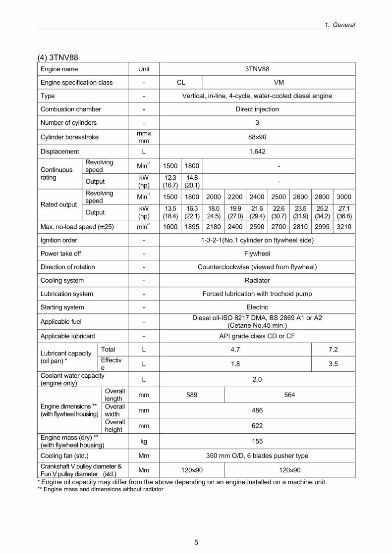
(4) 3TNV88 Engine name Unit 3TNV88
Engine specification class - CL VM
Type - Vertical, in-line, 4-cycle, water-cooled diesel engine
Combustion chamber - Direct injection
Number of cylinders - 3
Cylinder bore stroke mmmm 88 90
Displacement L 1.642 Revolving speed Min-1 1500 1800 - Continuous
rating Output kW (hp)
12.3(16.7)
14.8(20.1) -
Revolving speed Min-1 1500 1800 2000 2200 2400 2500 2600 2800 3000
Rated output Output kW
(hp) 13.5(18.4)
16.3(22.1)
18.024.5)
19.9(27.0)
21.6(29.4)
22.6 (30.7)
23.5 (31.9)
25.2(34.2)
27.1(36.8)
Max. no-load speed ( 25) min-1 1600 1895 2180 2400 2590 2700 2810 2995 3210
Ignition order - 1-3-2-1(No.1 cylinder on flywheel side)
Power take off - Flywheel
Direction of rotation - Counterclockwise (viewed from flywheel)
Cooling system - Radiator
Lubrication system - Forced lubrication with trochoid pump
Starting system - Electric
Applicable fuel - Diesel oil-ISO 8217 DMA, BS 2869 A1 or A2 (Cetane No.45 min.)
Applicable lubricant - API grade class CD or CF
Total L 4.7 7.2 Lubricant capacity (oil pan) * Effectiv
e L 1.8 3.5
Coolant water capacity (engine only) L 2.0
Overall length mm 589 564
Overall width mm 486 Engine dimensions **
(with flywheel housing) Overall height mm 622
Engine mass (dry) ** (with flywheel housing) kg 155
Cooling fan (std.) Mm 350 mm O/D, 6 blades pusher type Crankshaft V pulley diameter & Fun V pulley diameter (std.) Mm 120 90 120 90
* Engine oil capacity may differ from the above depending on an engine installed on a machine unit. **
Engine mass and dimensions without radiator
5
1. General
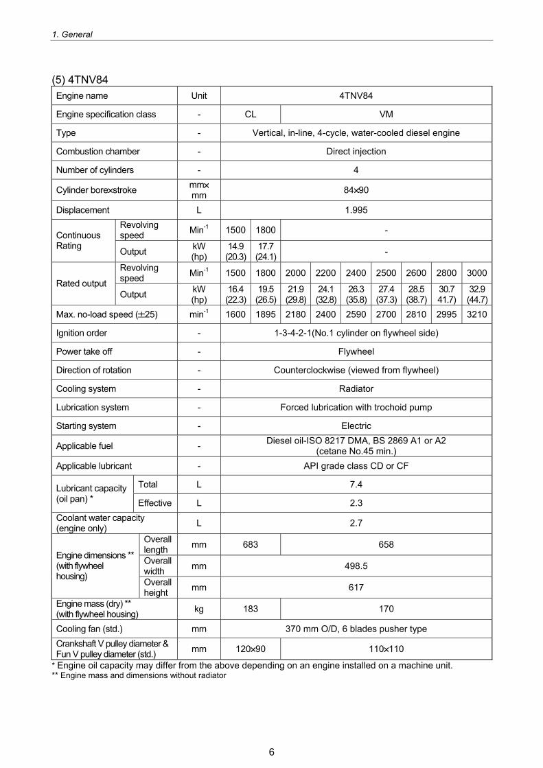
(5) 4TNV84 Engine name Unit 4TNV84
Engine specification class - CL VM
Type - Vertical, in-line, 4-cycle, water-cooled diesel engine
Combustion chamber - Direct injection
Number of cylinders - 4
Cylinder bore stroke mmmm 84 90
Displacement L 1.995 Revolving speed Min-1 1500 1800 - Continuous
Rating Output kW (hp)
14.9(20.3)
17.7(24.1) -
Revolving speed Min-1 1500 1800 2000 2200 2400 2500 2600 2800 3000
Rated output Output kW
(hp) 16.4(22.3)
19.5(26.5)
21.9(29.8)
24.1(32.8)
26.3(35.8)
27.4 (37.3)
28.5 (38.7)
30.741.7)
32.9(44.7)
Max. no-load speed ( 25) min-1 1600 1895 2180 2400 2590 2700 2810 2995 3210
Ignition order - 1-3-4-2-1(No.1 cylinder on flywheel side)
Power take off - Flywheel
Direction of rotation - Counterclockwise (viewed from flywheel)
Cooling system - Radiator
Lubrication system - Forced lubrication with trochoid pump
Starting system - Electric
Applicable fuel - Diesel oil-ISO 8217 DMA, BS 2869 A1 or A2 (cetane No.45 min.)
Applicable lubricant - API grade class CD or CF
Total L 7.4 Lubricant capacity (oil pan) * Effective L 2.3 Coolant water capacity (engine only) L 2.7
Overall length mm 683 658
Overall width mm 498.5
Engine dimensions ** (with flywheel housing) Overall
height mm 617
Engine mass (dry) ** (with flywheel housing) kg 183 170
Cooling fan (std.) mm 370 mm O/D, 6 blades pusher type Crankshaft V pulley diameter & Fun V pulley diameter (std.) mm 120 90 110 110
* Engine oil capacity may differ from the above depending on an engine installed on a machine unit. ** Engine mass and dimensions without radiator
6
1. General
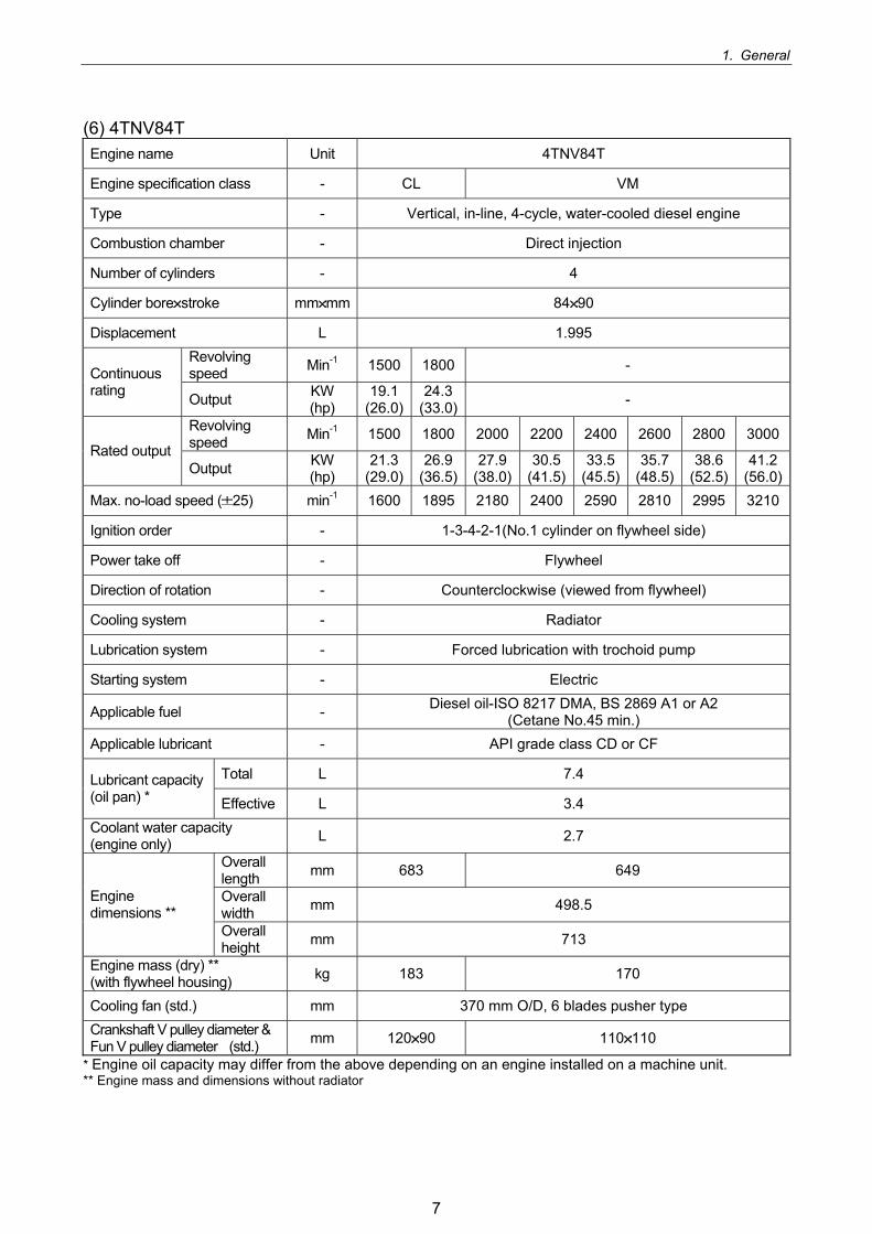
(6) 4TNV84T Engine name Unit 4TNV84T
Engine specification class - CL VM
Type - Vertical, in-line, 4-cycle, water-cooled diesel engine
Combustion chamber - Direct injection
Number of cylinders - 4
Cylinder bore stroke mm mm 84 90
Displacement L 1.995 Revolving speed Min-1 1500 1800 - Continuous
rating Output KW (hp)
19.1(26.0)
24.3(33.0) -
Revolving speed Min-1 1500 1800 2000 2200 2400 2600 2800 3000
Rated output Output KW
(hp) 21.3
(29.0)26.9
(36.5)27.9
(38.0)30.5
(41.5)33.5
(45.5) 35.7
(48.5) 38.6
(52.5)41.2
(56.0)Max. no-load speed ( 25) min-1 1600 1895 2180 2400 2590 2810 2995 3210
Ignition order - 1-3-4-2-1(No.1 cylinder on flywheel side)
Power take off - Flywheel
Direction of rotation - Counterclockwise (viewed from flywheel)
Cooling system - Radiator
Lubrication system - Forced lubrication with trochoid pump
Starting system - Electric
Applicable fuel - Diesel oil-ISO 8217 DMA, BS 2869 A1 or A2 (Cetane No.45 min.)
Applicable lubricant - API grade class CD or CF
Total L 7.4 Lubricant capacity (oil pan) * Effective L 3.4 Coolant water capacity (engine only) L 2.7
Overall length mm 683 649
Overall width mm 498.5 Engine
dimensions ** Overall height mm 713
Engine mass (dry) ** (with flywheel housing) kg 183 170
Cooling fan (std.) mm 370 mm O/D, 6 blades pusher type Crankshaft V pulley diameter & Fun V pulley diameter (std.) mm 120 90 110 110
* Engine oil capacity may differ from the above depending on an engine installed on a machine unit. ** Engine mass and dimensions without radiator
7
1. General
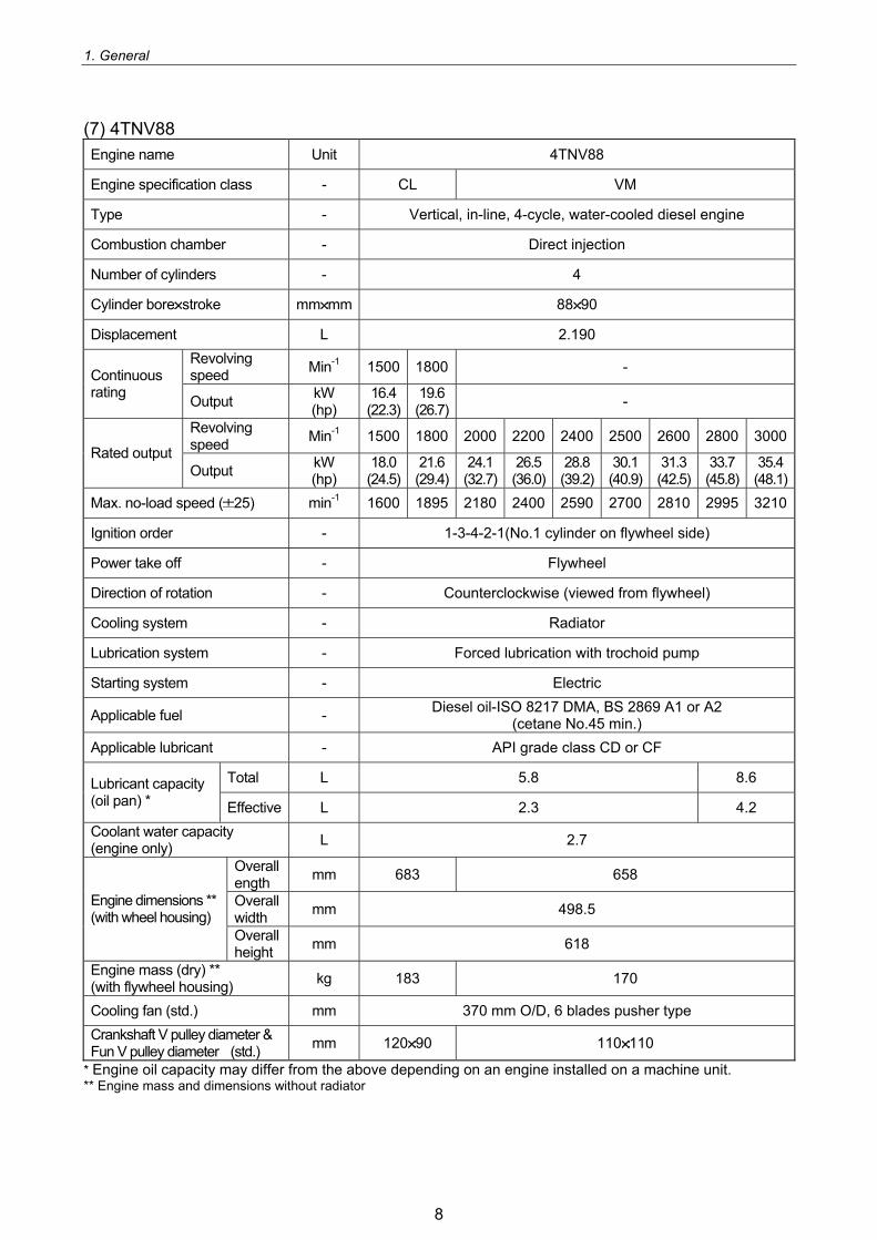
(7) 4TNV88 Engine name Unit 4TNV88
Engine specification class - CL VM
Type - Vertical, in-line, 4-cycle, water-cooled diesel engine
Combustion chamber - Direct injection
Number of cylinders - 4
Cylinder bore stroke mm mm 88 90
Displacement L 2.190 Revolving speed Min-1 1500 1800 - Continuous
rating Output kW (hp)
16.4(22.3)
19.6(26.7) -
Revolving speed Min-1 1500 1800 2000 2200 2400 2500 2600 2800 3000
Rated output Output kW
(hp) 18.0(24.5)
21.6(29.4)
24.1(32.7)
26.5(36.0)
28.8(39.2)
30.1 (40.9)
31.3 (42.5)
33.7(45.8)
35.4(48.1)
Max. no-load speed ( 25) min-1 1600 1895 2180 2400 2590 2700 2810 2995 3210
Ignition order - 1-3-4-2-1(No.1 cylinder on flywheel side)
Power take off - Flywheel
Direction of rotation - Counterclockwise (viewed from flywheel)
Cooling system - Radiator
Lubrication system - Forced lubrication with trochoid pump
Starting system - Electric
Applicable fuel - Diesel oil-ISO 8217 DMA, BS 2869 A1 or A2 (cetane No.45 min.)
Applicable lubricant - API grade class CD or CF
Total L 5.8 8.6 Lubricant capacity (oil pan) * Effective L 2.3 4.2 Coolant water capacity (engine only) L 2.7
Overall ength mm 683 658
Overall width mm 498.5 Engine dimensions **
(with wheel housing) Overall height mm 618
Engine mass (dry) ** (with flywheel housing) kg 183 170
Cooling fan (std.) mm 370 mm O/D, 6 blades pusher type Crankshaft V pulley diameter & Fun V pulley diameter (std.) mm 120 90 110 110
* Engine oil capacity may differ from the above depending on an engine installed on a machine unit. **
Engine mass and dimensions without radiator
8

1. General
(8) 4TNV94L Engine name Unit 4TNV94L
Engine specification class - CL VM
Type - Vertical, in-line, 4-cycle, water-cooled diesel engine
Combustion chamber - Direct injection
Number of cylinders - 4
Cylinder bore stroke mm mm 94 110
Displacement L 3.053 Revolving speed Min-1 1500 1800 - Continuous
rating Output kW (hp)
26.1 (35.5)
31.3 (42.5) -
Revolving speed Min-1 1500 1800 2000 2200 2400 2500
Rated output Output kW
(hp) 29.1
(39.5) 34.6
(47.0) 35.3
(48.0) 38.2
(52.0) 41.6
(56.5) 43.0
(58.5) Max. no-load speed ( 25) min-1 1600 1895 2180 2400 2590 2700
Ignition order - 1-3-4-2-1(No.1 cylinder on flywheel side)
Power take off - Flywheel
Direction of rotation - Counterclockwise (viewed from flywheel)
Cooling system - Radiator
Lubrication system - Forced lubrication with trochoid pump
Starting system - Electric
Applicable fuel - Diesel oil-ISO 8217 DMA, BS 2869 A1 or A2 (Cetane No.45 min.)
Applicable lubricant - API grade class CD or CF
Total L 10.2 Lubricant capacity (oil pan) * Effective L 4.5 Coolant water capacity (engine only) L 4.2
Overall length mm 719
Overall width mm 498 Engine dimensions **
(with flywheel housing) Overall height mm 717
Engine mass (dry) ** (with flywheel housing) kg 245
(equivalent to SAE#3)235
(equivalent to SAE#4) Cooling fan (std.) mm 410 mm O/D, 6 blades pusher type Crankshaft V pulley diameter & Fun V pulley diameter (std.) mm 130 130
* Engine oil capacity may differ from the above depending on an engine installed on a machine unit. ** Engine mass and dimensions without radiator
9
1. General
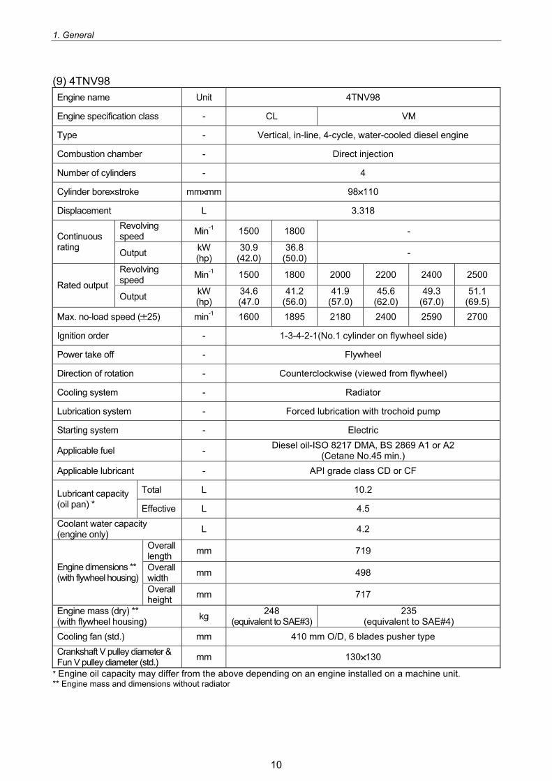
(9) 4TNV98 Engine name Unit 4TNV98
Engine specification class - CL VM
Type - Vertical, in-line, 4-cycle, water-cooled diesel engine
Combustion chamber - Direct injection
Number of cylinders - 4
Cylinder bore stroke mm mm 98 110
Displacement L 3.318 Revolving speed Min-1 1500 1800 - Continuous
rating Output kW (hp)
30.9 (42.0)
36.8 (50.0) -
Revolving speed Min-1 1500 1800 2000 2200 2400 2500
Rated output Output kW
(hp) 34.6 (47.0
41.2 (56.0)
41.9 (57.0)
45.6 (62.0)
49.3 (67.0)
51.1 (69.5)
Max. no-load speed ( 25) min-1 1600 1895 2180 2400 2590 2700
Ignition order - 1-3-4-2-1(No.1 cylinder on flywheel side)
Power take off - Flywheel
Direction of rotation - Counterclockwise (viewed from flywheel)
Cooling system - Radiator
Lubrication system - Forced lubrication with trochoid pump
Starting system - Electric
Applicable fuel - Diesel oil-ISO 8217 DMA, BS 2869 A1 or A2 (Cetane No.45 min.)
Applicable lubricant - API grade class CD or CF
Total L 10.2 Lubricant capacity (oil pan) * Effective L 4.5 Coolant water capacity (engine only) L 4.2
Overall length mm 719
Overall width mm 498 Engine dimensions **
(with flywheel housing) Overall height mm 717
Engine mass (dry) ** (with flywheel housing) kg 248
(equivalent to SAE#3)235
(equivalent to SAE#4) Cooling fan (std.) mm 410 mm O/D, 6 blades pusher type Crankshaft V pulley diameter & Fun V pulley diameter (std.) mm 130 130
* Engine oil capacity may differ from the above depending on an engine installed on a machine unit. ** Engine mass and dimensions without radiator
10
1. General
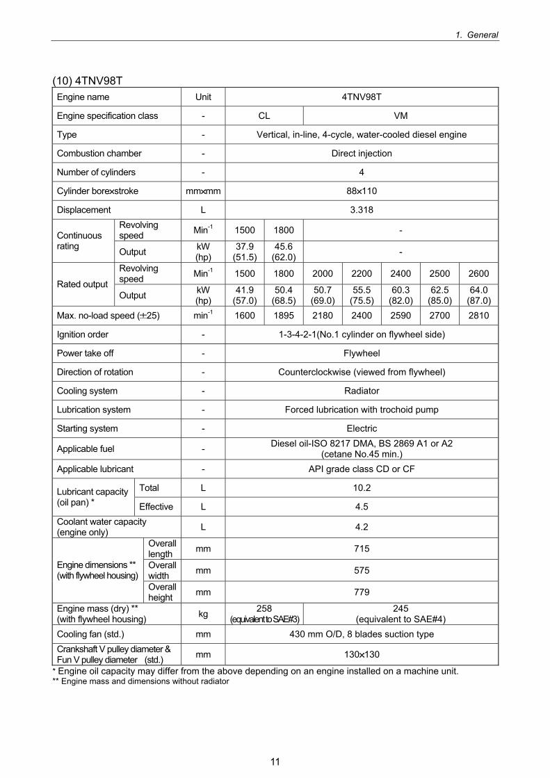
(10) 4TNV98T Engine name Unit 4TNV98T
Engine specification class - CL VM
Type - Vertical, in-line, 4-cycle, water-cooled diesel engine
Combustion chamber - Direct injection
Number of cylinders - 4
Cylinder bore stroke mm mm 88 110
Displacement L 3.318 Revolving speed Min-1 1500 1800 - Continuous
rating Output kW (hp)
37.9 (51.5)
45.6 (62.0) -
Revolving speed Min-1 1500 1800 2000 2200 2400 2500 2600
Rated output Output kW
(hp) 41.9
(57.0)50.4
(68.5)50.7
(69.0)55.5
(75.5)60.3
(82.0) 62.5
(85.0) 64.0
(87.0)Max. no-load speed ( 25) min-1 1600 1895 2180 2400 2590 2700 2810
Ignition order - 1-3-4-2-1(No.1 cylinder on flywheel side)
Power take off - Flywheel
Direction of rotation - Counterclockwise (viewed from flywheel)
Cooling system - Radiator
Lubrication system - Forced lubrication with trochoid pump
Starting system - Electric
Applicable fuel - Diesel oil-ISO 8217 DMA, BS 2869 A1 or A2 (cetane No.45 min.)
Applicable lubricant - API grade class CD or CF
Total L 10.2 Lubricant capacity (oil pan) * Effective L 4.5 Coolant water capacity (engine only) L 4.2
Overall length mm 715
Overall width mm 575 Engine dimensions **
(with flywheel housing) Overall height mm 779
Engine mass (dry) ** (with flywheel housing) kg 258
(equivalent to SAE#3)245
(equivalent to SAE#4) Cooling fan (std.) mm 430 mm O/D, 8 blades suction type Crankshaft V pulley diameter & Fun V pulley diameter (std.) mm 130 130
* Engine oil capacity may differ from the above depending on an engine installed on a machine unit. ** Engine mass and dimensions without radiator
11
1. General
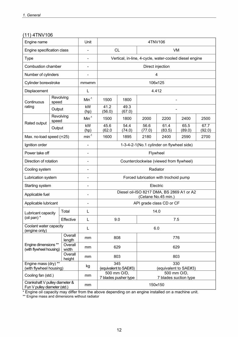
(11) 4TNV106 Engine name Unit 4TNV106
Engine specification class - CL VM
Type - Vertical, in-line, 4-cycle, water-cooled diesel engine
Combustion chamber - Direct injection
Number of cylinders - 4
Cylinder bore stroke mm mm 106 125
Displacement L 4.412 Revolving speed Min-1 1500 1800 - Continuous
rating Output kW (hp)
41.2 (56.0)
49.3 (67.0) -
Revolving speed Min-1 1500 1800 2000 2200 2400 2500
Rated output Output kW
(hp) 45.6 (62.0
54.4 (74.0)
56.6 (77.0)
61.4 (83.5)
65.5 (89.0)
67.7 (92.0)
Max. no-load speed ( 25) min-1 1600 1895 2180 2400 2590 2700
Ignition order - 1-3-4-2-1(No.1 cylinder on flywheel side)
Power take off - Flywheel
Direction of rotation - Counterclockwise (viewed from flywheel)
Cooling system - Radiator
Lubrication system - Forced lubrication with trochoid pump
Starting system - Electric
Applicable fuel - Diesel oil-ISO 8217 DMA, BS 2869 A1 or A2 (Cetane No.45 min.)
Applicable lubricant - API grade class CD or CF
Total L 14.0 Lubricant capacity (oil pan) * Effective L 9.0 7.5 Coolant water capacity (engine only) L 6.0
Overall length mm 808 776
Overall width mm 629 629 Engine dimensions **
(with flywheel housing) Overall height mm 803 803
Engine mass (dry) ** (with flywheel housing) kg 345
(equivalent to SAE#3)330
(equivalent to SAE#3)
Cooling fan (std.) mm 500 mm O/D, 7 blades pusher type
500 mm O/D, 7 blades suction type
Crankshaft V pulley diameter & Fun V pulley diameter (std.) mm 150 150
* Engine oil capacity may differ from the above depending on an engine installed on a machine unit. ** Engine mass and dimensions without radiator
12
1. General
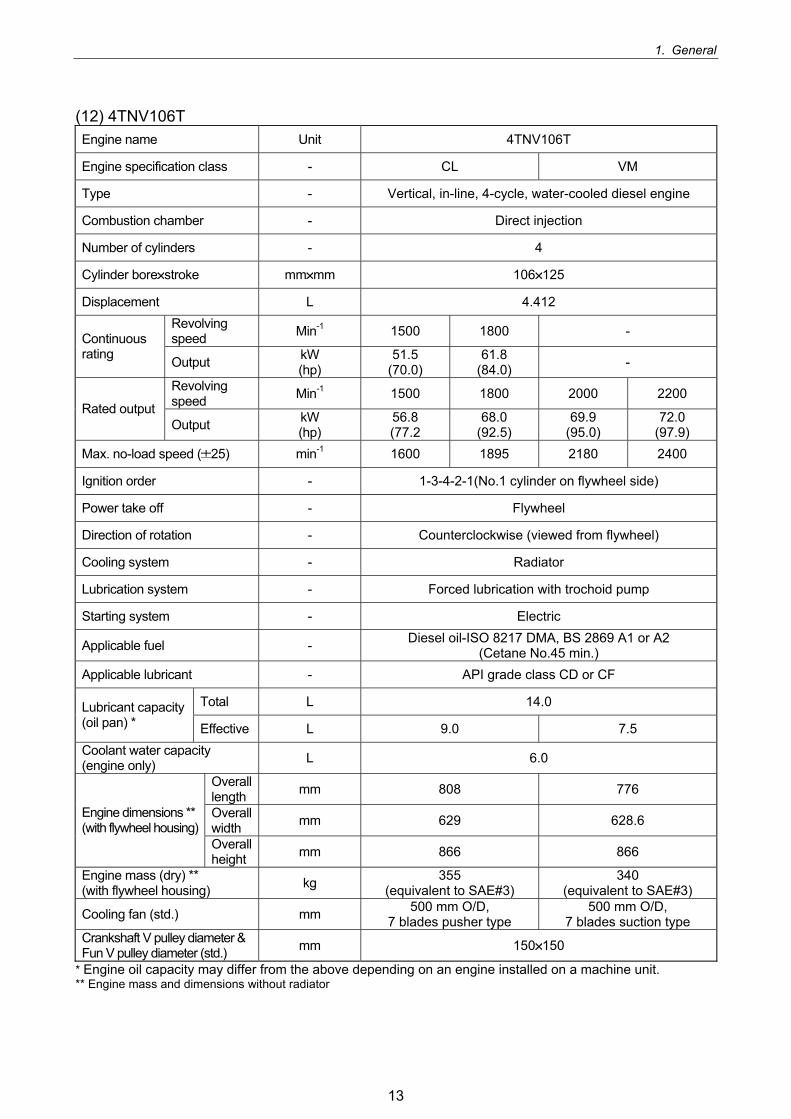
(12) 4TNV106T Engine name Unit 4TNV106T
Engine specification class - CL VM
Type - Vertical, in-line, 4-cycle, water-cooled diesel engine
Combustion chamber - Direct injection
Number of cylinders - 4
Cylinder bore stroke mm mm 106 125
Displacement L 4.412 Revolving speed Min-1 1500 1800 - Continuous
rating Output kW (hp)
51.5 (70.0)
61.8 (84.0) -
Revolving speed Min-1 1500 1800 2000 2200
Rated output Output kW
(hp) 56.8 (77.2
68.0 (92.5)
69.9 (95.0)
72.0 (97.9)
Max. no-load speed ( 25) min-1 1600 1895 2180 2400
Ignition order - 1-3-4-2-1(No.1 cylinder on flywheel side)
Power take off - Flywheel
Direction of rotation - Counterclockwise (viewed from flywheel)
Cooling system - Radiator
Lubrication system - Forced lubrication with trochoid pump
Starting system - Electric
Applicable fuel - Diesel oil-ISO 8217 DMA, BS 2869 A1 or A2 (Cetane No.45 min.)
Applicable lubricant - API grade class CD or CF
Total L 14.0 Lubricant capacity (oil pan) * Effective L 9.0 7.5 Coolant water capacity (engine only) L 6.0
Overall length mm 808 776
Overall width mm 629 628.6 Engine dimensions **
(with flywheel housing) Overall height mm 866 866
Engine mass (dry) ** (with flywheel housing) kg 355
(equivalent to SAE#3) 340
(equivalent to SAE#3)
Cooling fan (std.) mm 500 mm O/D, 7 blades pusher type
500 mm O/D, 7 blades suction type
Crankshaft V pulley diameter & Fun V pulley diameter (std.) mm 150 150
* Engine oil capacity may differ from the above depending on an engine installed on a machine unit. ** Engine mass and dimensions without radiator
13
1. General
1.3 Fuel Oil, Lubricating Oil and Coolant Water
1.3.1 Fuel oil
IMPORTANT: Only use the recommended fuel to obtain the best engine performance and prevent damage of parts, also prevent air pollution.
(1) Selection of fuel oil Use the following diesel fuels for best engine performance: BS 2869 A1 or A2 Fuels equivalent to Japanese Industrial Standard, JIS. No. K2204-2 Fuel cetane number should be 45 or greater
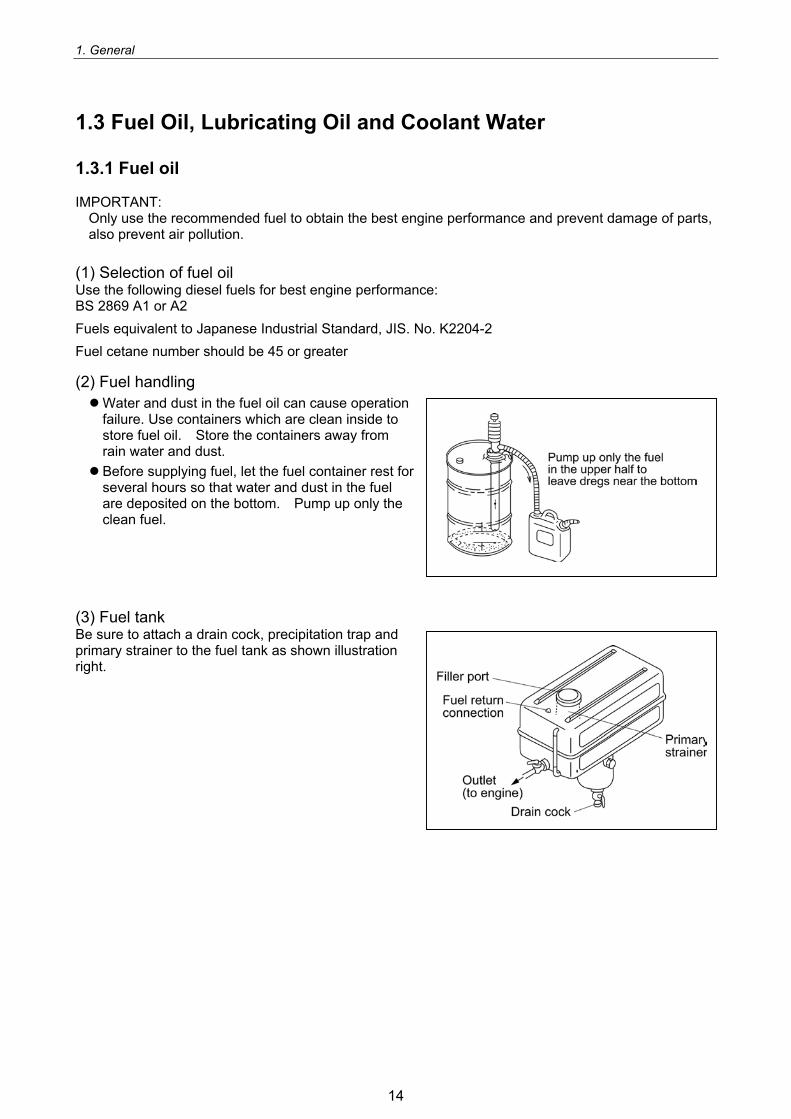
(2) Fuel handling Water and dust in the fuel oil can cause operation failure. Use containers which are clean inside to store fuel oil. Store the containers away from rain water and dust. Before supplying fuel, let the fuel container rest for several hours so that water and dust in the fuel are deposited on the bottom. Pump up only the clean fuel.
(3) Fuel tank Be sure to attach a drain cock, precipitation trap and primary strainer to the fuel tank as shown illustration right.
14
1. General
1.3.2 Lubricating oil
IMPORTANT: Use of other than the specified engine oil may cause inner parts seizure or early wear, leading to shorten the engine service life.
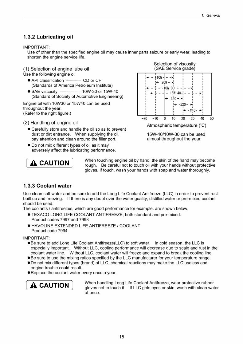
(1) Selection of engine lube oil Use the following engine oil API classification CD or CF (Standards of America Petroleum Institute) SAE viscosity 10W-30 or 15W-40 (Standard of Society of Automotive Engineering)
Engine oil with 10W30 or 15W40 can be used throughout the year. (Refer to the right figure.)
(2) Handling of engine oil Carefully store and handle the oil so as to prevent dust or dirt entrance. When supplying the oil, pay attention and clean around the filler port. Do not mix different types of oil as it may adversely affect the lubricating performance.
When touching engine oil by hand, the skin of the hand may become rough. Be careful not to touch oil with your hands without protective gloves. If touch, wash your hands with soap and water thoroughly.
1.3.3 Coolant water Use clean soft water and be sure to add the Long Life Coolant Antifreeze (LLC) in order to prevent rust built up and freezing. If there is any doubt over the water guality, distilled water or pre-mixed coolant should be used. The coolants / antifreezes, which are good performance for example, are shown below. TEXACO LONG LIFE COOLANT ANTIFREEZE, both standard and pre-mixed. Product codes 7997 and 7998 HAVOLINE EXTENDED LIFE ANTIFREEZE / COOLANT Product code 7994
IMPORTANT: Be sure to add Long Life Coolant Antifreeze(LLC) to soft water. In cold season, the LLC is especially important. Without LLC, cooling performance will decrease due to scale and rust in the coolant water line. Without LLC, coolant water will freeze and expand to break the cooling line. Be sure to use the mixing ratios specified by the LLC manufacturer for your temperature range. Do not mix different types (brand) of LLC, chemical reactions may make the LLC useless and engine trouble could result. Replace the coolant water every once a year.
When handling Long Life Coolant Antifreeze, wear protective rubber gloves not to touch it. If LLC gets eyes or skin, wash with clean water at once.
15
1. General
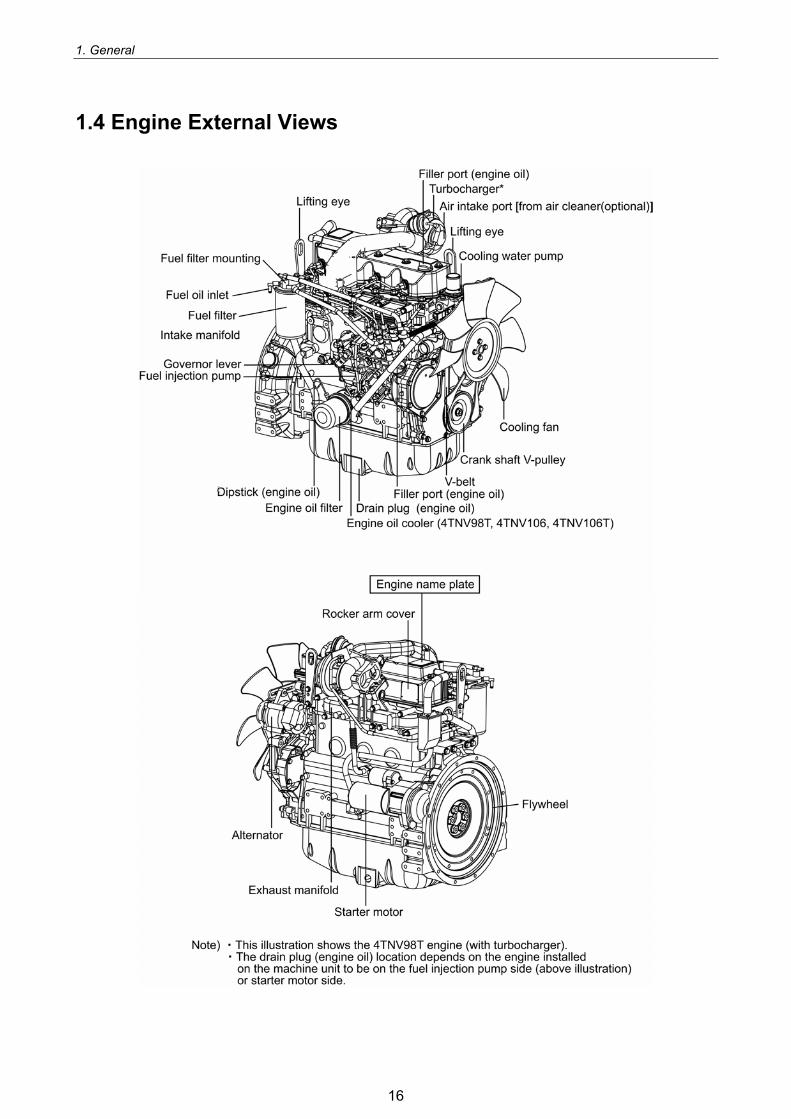
1.4 Engine External Views
16


![home.komatsu · 2019-03-08 · コマツ 4d88e 4サイクル、水冷直列式、直接噴射式 2.189[2189] 電子式hst 出力軸制動密閉湿式多板ディスク 15.5/60-18-8pr](https://img.dokumen.tips/doc/110x75/5e7a1357f1dfaf72ac211388/homekomatsu-2019-03-08-ff-4d88e-4ficic.jpg)