Embed Size (px)
Citation preview

SUBJECT: MP4000 Alarm Descriptions BULLETIN: C 100 DATE: June 19, 2013
ALARM LIST Where it is possible the alarm number is kept the same as for MP-3000. MP-3000 holds alarm number from 0 to 127. New alarms not matching the MP-3000 scheme is allocated above 127.
MP-4000 Alarm List
(Software version 2.4.3 or later)
No Alarm text In use in
normal run
In use during
test
0 SUP AIR SENSOR OPEN CIRCUIT. N T
1 SUP AIR SENSOR SHORT CIRCUIT. N T
2 RET AIR SENSOR OPEN CIRCUIT. N T
3 RET AIR SENSOR SHORT CIRCUIT. N T
4 EVA COIL SENSOR OPEN CIRCUIT. N T
5 EVA COIL SENSOR SHORT CIRCUIT. N T
6 COMP CURRENT TOO HIGH. T
7 COMP CURRENT TOO LOW T
10 HEATER CURRENT TOO HIGH. T
11 HEATER CURRENT TOO LOW. T
12 EVA HIGH CURRENT TOO HIGH. T
13 EVA HIGH CURRENT TOO LOW. T
14 EVA LOW CURRENT TOO HIGH. T
15 EVA LOW CURRENT TOO LOW. T
16 CON CURRENT TOO HIGH. T
17 CON CURRENT TOO LOW. T
18 POWER SUPPLY PHASE ERROR. N T
19 TEMP TOO FAR FROM SETPOINT. N
20 DEFROST TOO LONG. N T
22 CAPACITY TEST 1 ERROR. T
23 CAPACITY TEST 2 ERROR. T
26 VAPOR. INJECTION ERROR T
Service Bulletin

MP-4000 Alarm List
(Software version 2.4.3 or later)
No Alarm text In use in
normal run
In use during
test
31 LOW PRESS CUTOUT N T
32 CON AIR SENSOR OPEN CIRCUIT. N T
33 CON AIR SENSOR SHORT CIRCUIT. N T
34 AMB AIR SENSOR OPEN CIRCUIT. N T
35 AMB AIR SENSOR SHORT CIRCUIT. N T
43 RET AIR TEMP TOO HIGH. N T
44 RET AIR TEMP TOO LOW N
51 VOLTAGE TOO LOW. N T
52 PROBE ERROR. N T
53 HIGH PRESSURE SWITCH OFF. T
54 HIGH PRESSURE SWITCH ON. T
56 COMPRESSOR TEMP TOO HIGH. N
57 FAE DEVICE ERROR N T
58 PHASE SENSOR ERROR T
59 DELTA CUR ERROR. N T
60 HUMIDITY SENSOR ERROR. T
65 CO2 TOO HIGH. N
66 CO2 TOO LOW. N
68 GAS ANALYSER ERROR. N T
69 GAS ANALYSER CALIBRATION. N T
70 O2_SENSOR ERROR T
71 CO2 SENSOR ERROR T
97 COMP SENSOR OPEN CIRCUIT. N T
98 COMP SENSOR SHORT CIRCUIT. N T
119 DIGITAL VALVE ERROR. T
120 SUCTION PRESSURE SENSOR ERROR. N T
121 DISCHARGE PRESSURE SENSOR ERROR. N T
122 O2 SENSOR CALIBRATION ERROR T
123 DATALOGGER BATTERY ERROR N T
124 COLD TREATMENT RESTART N
127 ALARM_GENERAL_UNIT_ERROR N T
128 SUPPLY AIR TEMPERATURE PROBE ERROR N T
129 RETURN AIR TEMPERATURE PROBE ERROR N T
130 EVAPORATOR COIL TEMPERATURE PROBE ERROR N T
131 AMB - COND TEMPERATURE PROBE ERROR N T
132 POWER MODULE SENSOR ERROR N T
133 POWER MODULE NETWORK ERROR N T
134 CONTROLLER ERROR N T
135 POWER MODULE ERROR N T

MP-4000 Alarm List
(Software version 2.4.3 or later)
No Alarm text In use in
normal run
In use during
test
136 TRANSDUCER CIRCUIT ERROR N T
137 SENSOR SYSTEM OVERLOAD N T
138 AVL SENSOR ERROR N T
139 INTERNAL FILE HANDLING ERROR N T
140 EVAPORATOR SECTION TOO HOT N T

ALARM DESCRIPTIONS Each alarm is described with a description of the alarm and the recommended corrective action.
Some alarms are special related to specific customer requests and may not be active for standard
settings.
If the specific alarm depends on special customer options it is noticed in the description setting.
Alarm #0000
Supply Air Temperature Sensor Open Circuit
Description Corrective Action
• When the sensor circuit resistance is above 1300Ω.
• Indicates:
- Open circuit.
- Defective or wrong sensor.
- Defective wiring.
- Defective controller.
• Check for damaged sensor wires.
• Check for sensor connections at controller.
• The sensor is a pt1000 – 2 wire sensor, connected to
the MP-4000 at connector J3 pin 1 and 2. CM-4000
upper left connector J3, 17 pin wide, pin number 1 is
the right pin, seen at the backside of the controller.
• The 2 sensor wires can be switched without affecting
the measurement.
• Disconnect the sensor, use an Ohm (Ω) measuring
device, measure the electrical resistance between the
two sensor wires.
The sensor can’t be examined without disconnecting
it.
The electrical resistance towards chassis must be
above meg ohm (MΩ) range.
• The sensor is a pt1000 – positive temperature
coefficient, which means that the electrical resistance
of the sensor increases with temperature.
The sensor is defined to be 1000Ω@ 0°C.
Normal condition measuring with disconnected
sensor is 960Ω@-10°C, 1000Ω@0°C,1039Ω@+10°C,
1058Ω@+15°C, 1078Ω@+20°C.
The valid measuring limit for this pt1000 sensor is -
100°C(602Ω) +75°C(approx 1300Ω).

Alarm #0001
Supply Air Temperature Sensor Short Circuit
Description Corrective Action
• When the sensor circuit resistance is below 602Ω.
• Indicates:
- Short circuit.
- Defective or wrong sensor.
- Defective wiring.
- Defective controller.
• Check for damaged sensor wires.
• Check for sensor connections at controller.
• The sensor is a pt1000 – 2 wire sensor, connected to
the MP-4000 at connector J3 pin 1 and 2. CM-4000
upper left connector J3, 17 pin wide, pin number 1 is
the right pin, seen at the backside of the controller.
• The 2 sensor wires can be switched without affecting
the measurement.
• Disconnect the sensor, use an Ohm (Ω) measuring
device, measure the electrical resistance between the
two sensor wires.
The sensor can’t be examined without disconnecting
it.
The electrical resistance towards chassis must be
above meg ohm (MΩ) range.
• The sensor is a pt1000 – positive temperature
coefficient, which means that the electrical resistance
of the sensor increases with temperature.
The sensor is defined to be 1000Ω@ 0°C.
Normal condition measuring with disconnected
sensor is 960Ω@-10°C, 1000Ω@0°C,1039Ω@+10°C,
1058Ω@+15°C, 1078Ω@+20°C.
The valid measuring limit for this pt1000 sensor is -
100°C(602Ω) +75°C(approx 1300Ω).

Alarm #0002
Return Air Temperature Sensor Open Circuit
Description Corrective Action
• When the sensor circuit resistance is above 1300Ω.
• Indicates:
- Open circuit.
- Defective or wrong sensor.
- Defective wiring.
- Defective controller.
• Check for damaged sensor wires.
• Check for sensor connections at controller.
• The sensor is a pt1000 – 2 wire sensor, connected to
the MP-4000 at connector J3 pin 3 and 4. CM-4000
upper left connector J3, 17 pin wide, pin number 1 is
the right pin, seen at the backside of the controller.
• The 2 sensor wires can be switched without affecting
the measurement.
• Disconnect the sensor, use an Ohm (Ω) measuring
device, measure the electrical resistance between the
two sensor wires.
The sensor can’t be examined without disconnecting
it.
The electrical resistance towards chassis must be
above meg ohm (MΩ) range.
• The sensor is a pt1000 – positive temperature
coefficient, which means that the electrical resistance
of the sensor increases with temperature.
The sensor is defined to be 1000Ω@ 0°C.
Normal condition measuring with disconnected
sensor is 960Ω@-10°C, 1000Ω@0°C,1039Ω@+10°C,
1058Ω@+15°C, 1078Ω@+20°C.
The valid measuring limit for this pt1000 sensor is -
100°C(602Ω) +75°C(approx 1300Ω).

Alarm #0003
Return Air Temperature Sensor Short Circuit
Description Corrective Action
• When the sensor circuit resistance is below 602Ω.
• Indicates:
- Short circuit.
- Defective or wrong sensor.
- Defective wiring.
- Defective controller.
• Check for damaged sensor wires.
• Check for sensor connections at controller.
• The sensor is a pt1000 – 2 wire sensor, connected to
the MP-4000 at connector J3 pin 3 and 4. CM-4000
upper left connector J3, 17 pin wide, pin number 1 is
the right pin, seen at the backside of the controller.
• The 2 sensor wires can be switched without affecting
the measurement.
• Disconnect the sensor, use an Ohm (Ω) measuring
device, measure the electrical resistance between the
two sensor wires.
The sensor can’t be examined without disconnecting
it.
The electrical resistance towards chassis must be
above meg ohm (MΩ) range.
• The sensor is a pt1000 – positive temperature
coefficient, which means that the electrical resistance
of the sensor increases with temperature.
The sensor is defined to be 1000Ω@ 0°C.
Normal condition measuring with disconnected
sensor is 960Ω@-10°C, 1000Ω@0°C,1039Ω@+10°C,
1058Ω@+15°C, 1078Ω@+20°C.
The valid measuring limit for this pt1000 sensor is -
100°C(602Ω) +75°C(approx 1300Ω).

Alarm #0004
Evaporator Coil Temperature Sensor Open Circuit
Description Corrective Action
• When the sensor circuit resistance is above 1300Ω.
• Indicates:
- Open circuit.
- Defective or wrong sensor.
- Defective wiring.
- Defective controller.
• Check for damaged sensor wires.
• Check for sensor connections at controller.
• The sensor is a pt1000 – 2 wire sensor, connected to
the MP-4000 at connector J3 pin 5 and 6. CM-4000
upper left connector J3, 17 pin wide, pin number 1 is
the right pin, seen at the backside of the controller.
• The 2 sensor wires can be switched without affecting
the measurement.
• Disconnect the sensor, use an Ohm (Ω) measuring
device, measure the electrical resistance between the
two sensor wires.
The sensor can’t be examined without disconnecting
it.
The electrical resistance towards chassis must be
above meg ohm (MΩ) range.
• The sensor is a pt1000 – positive temperature
coefficient, which means that the electrical resistance
of the sensor increases with temperature.
The sensor is defined to be 1000Ω@ 0°C.
Normal condition measuring with disconnected
sensor is 960Ω@-10°C, 1000Ω@0°C,1039Ω@+10°C,
1058Ω@+15°C, 1078Ω@+20°C.
The valid measuring limit for this pt1000 sensor is -
100°C(602Ω) +75°C(approx 1300Ω).

Alarm #0005
Evaporator Coil Temperature Sensor Short Circuit
Description Corrective Action
• When the sensor circuit resistance is below 602Ω.
• Indicates:
- Short circuit.
- Defective or wrong sensor.
- Defective wiring.
- Defective controller.
• Check for damaged sensor wires.
• Check for sensor connections at controller.
• The sensor is a pt1000 – 2 wire sensor, connected to
the MP-4000 at connector J3 pin 5 and 6. CM-4000
upper left connector J3, 17 pin wide, pin number 1 is
the right pin, seen at the backside of the controller.
• The 2 sensor wires can be switched without affecting
the measurement.
• Disconnect the sensor, use an Ohm (Ω) measuring
device, measure the electrical resistance between the
two sensor wires.
The sensor can’t be examined without disconnecting
it.
The electrical resistance towards chassis must be
above meg ohm (MΩ) range.
• The sensor is a pt1000 – positive temperature
coefficient, which means that the electrical resistance
of the sensor increases with temperature.
The sensor is defined to be 1000Ω@ 0°C.
Normal condition measuring with disconnected
sensor is 960Ω@-10°C, 1000Ω@0°C,1039Ω@+10°C,
1058Ω@+15°C, 1078Ω@+20°C.
The valid measuring limit for this pt1000 sensor is -
100°C(602Ω) +75°C(approx 1300Ω).

Alarm #0006
Compressor Current Too High
Description Corrective Action
• Occurs during pretrip (PTI) or function test only.
• During compressor test, if Compressor power
consumption is 25% above expected current draw or
compressor phase current level differs 33% or more.
• If both alarm #6 and #7 is active this indicates too
high phase difference.
• Expected compressor current is a function of the
surrounding conditions.
• Indicates:
- Defective Digital Control valve.
- Defective compressor.
- Defective volt or amp meter on power module.
- Inaccurate condenser or evaporator
temperature measurement.
- Excessive condenser pressure due to air or
wrong refrigerant in system, or refrigerant over
charge.
• Check evaporator and condenser sensor
temperatures for correct value (± 5 °C [± 9 F]) by
viewing Data menu.
• To determine the current draw measurement, enter
Manual Function Test menu. Start and check current
draw of the following components separately and
together: compressor, compressor full loaded,
condenser fan and evaporator fan (high or low).
• Check power supply volts on all 3 phases.

Alarm #0007
Compressor Current Too Low
Description Corrective Action
• Occurs during pretrip (PTI) or function test only.
• During compressor test, if Compressor power
consumption is 25% below expected current draw or
compressor phase current level differs 33% or more.
• If both alarm #6 and #7 is active this indicates too
high phase difference.
• Expected compressor current is a function of the
surrounding conditions.
• Indicates:
- Defective or open high pressure cutout switch.
- Defective or open low pressure cutout switch or
transmitter if mounted.
- Defective compressor relay.
- Defective volt or amp meter on power module.
- Low refrigerant charge.
- Defective compressor.
- Defective volt or amp meter on power module.
- Inaccurate condenser or evaporator
temperature measurement.
- Defective or open compressor motor internal
over temperature protection switch.
• Check evaporator, condenser sensor temperatures
for correct value (± 5 °C [± 9 F]) by viewing Data
menu.
• To determine the current draw measurement, enter
Manual Function Test menu. Start and check current
draw of the following components separately and
together: compressor, compressor full loaded,
condenser fan and evaporator fan (high or low).
• Check discharge and suction pressure gauge readings.
• Check power supply volts on all 3 phases.

Alarm #0010
Heater Current Too High
Description Corrective Action
• Occurs during pretrip (PTI) or function test only.
• Heater power consumption is 25% above expected
current draw or phase current level differs 33% or
more.
• If both alarm #10 and #11 is active this indicates too
high phase difference.
• Expected heater current is a function of the heating
element resistance and the power supply voltage.
• The Magnum+ may be equipped with extended
heating capability.
• Normal heating element 4kw@460VAC
- above approximately 6,3Amp / 5,3Amp.
• Extended heating element 6kw@460VAC
- above approximately 9,4Amp / 8,1Amp.
• Indicates:
- Incorrect heaters or heater connections.
- Defective heating elements.
- Defective volt or amp meter on power module.
• Enter Manual Function Test and turn heaters on.
Check current draw on each phase. Evaluate current
draw in relation to expected values.
• Enter configuration menu and check the heating
element setting.
• Check heater resistance.
• The electrical resistance towards chassis must be
above meg ohm (MΩ) range.
• Normal heating element 4kw@460VAC
- expects 5,0Amp@460VAC
- expects 4,3Amp@400VAC
- expected resistance 99Ω on each leg.
• Extended heating element 6kw@460VAC
- expects 7,5Amp@460VAC
- expects 6,5Amp@400VAC
- expected resistance 66Ω on each leg.
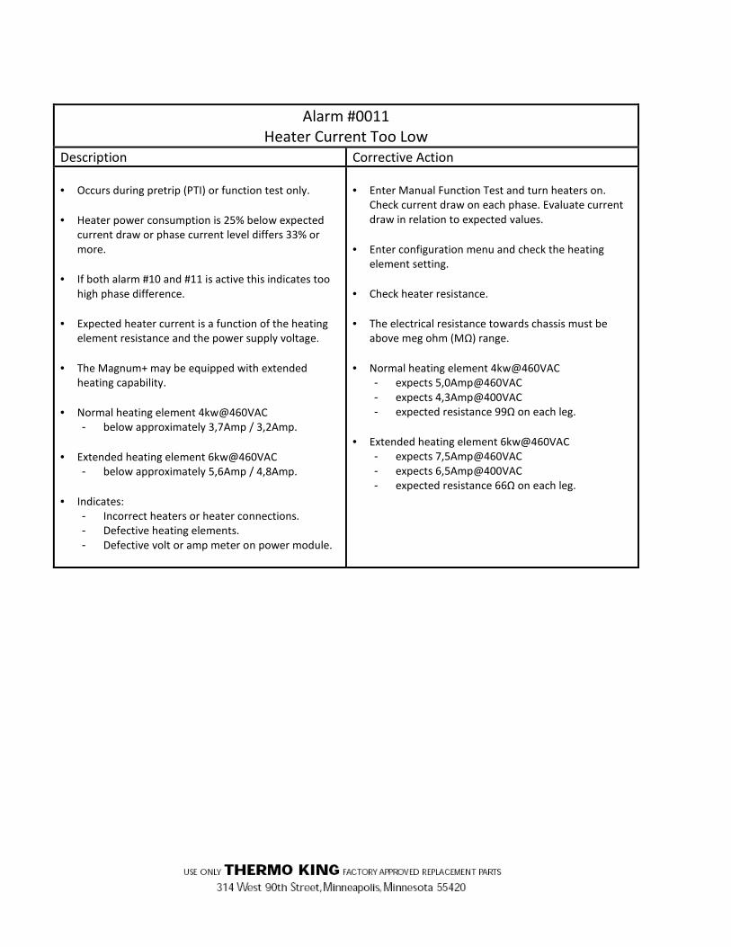
Alarm #0011
Heater Current Too Low
Description Corrective Action
• Occurs during pretrip (PTI) or function test only.
• Heater power consumption is 25% below expected
current draw or phase current level differs 33% or
more.
• If both alarm #10 and #11 is active this indicates too
high phase difference.
• Expected heater current is a function of the heating
element resistance and the power supply voltage.
• The Magnum+ may be equipped with extended
heating capability.
• Normal heating element 4kw@460VAC
- below approximately 3,7Amp / 3,2Amp.
• Extended heating element 6kw@460VAC
- below approximately 5,6Amp / 4,8Amp.
• Indicates:
- Incorrect heaters or heater connections.
- Defective heating elements.
- Defective volt or amp meter on power module.
• Enter Manual Function Test and turn heaters on.
Check current draw on each phase. Evaluate current
draw in relation to expected values.
• Enter configuration menu and check the heating
element setting.
• Check heater resistance.
• The electrical resistance towards chassis must be
above meg ohm (MΩ) range.
• Normal heating element 4kw@460VAC
- expects 5,0Amp@460VAC
- expects 4,3Amp@400VAC
- expected resistance 99Ω on each leg.
• Extended heating element 6kw@460VAC
- expects 7,5Amp@460VAC
- expects 6,5Amp@400VAC
- expected resistance 66Ω on each leg.

Alarm #0012
Evaporator Fan High Speed Current Too High
Description Corrective Action
• Occurs during pretrip (PTI) or function test only.
• Fan power consumption is 33% above expected
current draw or phase current level differs 33% or
more.
• If both alarm #12 and #13 is active this indicates too
high phase difference.
• Expected fan current is a function of the power line
frequency and the supply voltage.
• With 20’ setting above approximately
- 3,4Amp@400VAC/50Hz
- 4,2Amp@460VAC/60Hz
• With 40’ setting above approximately
- 2,7Amp@400VAC/50Hz
- 3,4Amp@460VAC/60Hz
• Indicates:
- Defective or stuck evaporator fan motor.
- Incorrect motor or motor connections.
- Defective volt or amp meter on power module.
• Open evaporator door and make sure all fans rotate
freely.
• Enter Manual Function Test and start evaporator fans
on high speed. Make sure all fans start on high speed.
Check fan motor volts and amps.
• With 20’ setting expect
- 2,4Amp@400VAC/50Hz
- 3,1Amp@460VAC/60Hz
• With 40’ setting expect
- 1,8Amp@400VAC/50Hz
- 2,4Amp@460VAC/60Hz
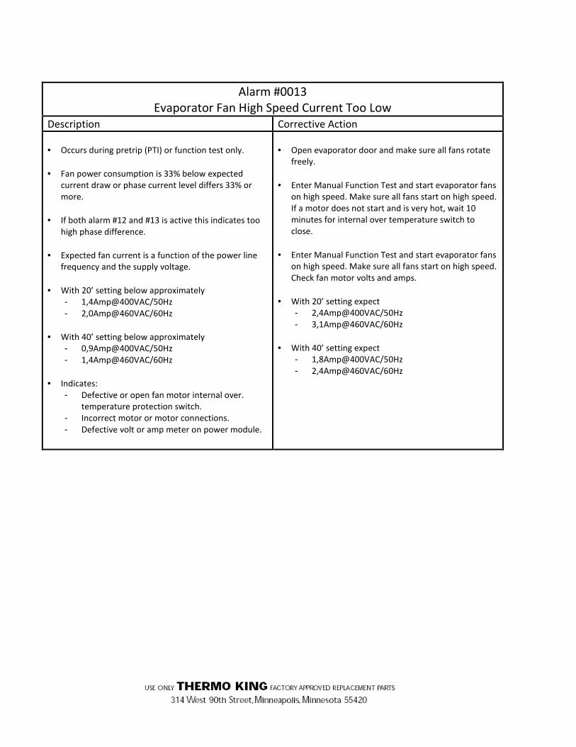
Alarm #0013
Evaporator Fan High Speed Current Too Low
Description Corrective Action
• Occurs during pretrip (PTI) or function test only.
• Fan power consumption is 33% below expected
current draw or phase current level differs 33% or
more.
• If both alarm #12 and #13 is active this indicates too
high phase difference.
• Expected fan current is a function of the power line
frequency and the supply voltage.
• With 20’ setting below approximately
- 1,4Amp@400VAC/50Hz
- 2,0Amp@460VAC/60Hz
• With 40’ setting below approximately
- 0,9Amp@400VAC/50Hz
- 1,4Amp@460VAC/60Hz
• Indicates:
- Defective or open fan motor internal over.
temperature protection switch.
- Incorrect motor or motor connections.
- Defective volt or amp meter on power module.
• Open evaporator door and make sure all fans rotate
freely.
• Enter Manual Function Test and start evaporator fans
on high speed. Make sure all fans start on high speed.
If a motor does not start and is very hot, wait 10
minutes for internal over temperature switch to
close.
• Enter Manual Function Test and start evaporator fans
on high speed. Make sure all fans start on high speed.
Check fan motor volts and amps.
• With 20’ setting expect
- 2,4Amp@400VAC/50Hz
- 3,1Amp@460VAC/60Hz
• With 40’ setting expect
- 1,8Amp@400VAC/50Hz
- 2,4Amp@460VAC/60Hz

Alarm #0014
Evaporator Fan Low Speed Current Too High
Description Corrective Action
• Occurs during pretrip (PTI) or function test only.
• Fan power consumption is 33% above expected
current draw or phase current level differs 33% or
more.
• If both alarm #14 and #15 is active this indicates too
high phase difference.
• Expected fan current is a function of the power line
frequency and the supply voltage.
• With 20’ setting above approximately
- 1,0Amp@400VAC/50Hz
- 1,2Amp@460VAC/60Hz
• With 40’ setting above approximately
- 1,0Amp@400VAC/50Hz
- 1,2Amp@460VAC/60Hz
• Indicates:
- Defective or stuck evaporator fan motor.
- Incorrect motor or motor connections.
- Defective volt or amp meter on power module.
• Open evaporator door and make sure all fans rotate
freely.
• Enter Manual Function Test and start evaporator fans
on low speed. Make sure all fans start on low speed.
Check fan motor volts and amps.
• With 20’ setting expect
- 0,8Amp@400VAC/50Hz
- 0,9Amp@460VAC/60Hz
• With 40’ setting expect
- 0,8Amp@400VAC/50Hz
- 0,9Amp@460VAC/60Hz

Alarm #0015
Evaporator Fan Low Speed Current Too Low
Description Corrective Action
• Occurs during pretrip (PTI) or function test only.
• Fan power consumption is 33% below expected
current draw or phase current level differs 33% or
more.
• If both alarm #14 and #15 is active this indicates too
high phase difference.
• Expected fan current is a function of the power line
frequency and the supply voltage.
• With 20’ setting below approximately
- 0,5Amp@400VAC/50Hz
- 0,6Amp@460VAC/60Hz
• With 40’ setting below approximately
- 0,5Amp@400VAC/50Hz
- 0,6Amp@460VAC/60Hz
• Indicates:
- Defective or open fan motor internal over
temperature protection switch.
- Incorrect motor or motor connections.
- Defective volt or amp meter on power module.
• Open evaporator door and make sure all fans rotate
freely.
• Enter Manual Function Test and start evaporator fans
on high speed. Make sure all fans start on high speed.
If a motor does not start and is very hot, wait 10
minutes for internal over temperature switch to
close.
• Enter Manual Function Test and start evaporator fans
on high speed. Make sure all fans start on high speed.
Check fan motor volts and amps.
• With 20’ setting expect
- 0,8Amp@400VAC/50Hz
- 0,9Amp@460VAC/60Hz
• With 40’ setting expect
- 0,8Amp@400VAC/50Hz
- 0,9Amp@460VAC/60Hz

Alarm #0016
Condenser Fan Current Too High
Description Corrective Action
• Occurs during pretrip (PTI) or function test only.
• Fan power consumption is 33% above expected
current draw or phase current level differs 33% or
more.
• If both alarm #16 and #17 is active this indicates too
high phase difference.
• Expected fan current is a function of the power line
frequency and the supply voltage.
• Above approximately
- 1,5Amp@400VAC/50Hz
- 1,8Amp@460VAC/60Hz
• Indicates:
- Defective or stuck condenser fan motor.
- Incorrect motor or motor connections.
- Defective volt or amp meter on power module.
• Enter Manual Function Test and start condenser fan.
Make sure the fan starts.
• Check fan motor volts and amps.
• Expect
- 1,0Amp@400VAC/50Hz
- 1,2Amp@460VAC/60Hz

Alarm #0017
Condenser Fan Current Too Low
Description Corrective Action
• Occurs during pretrip (PTI) or function test only.
• Fan power consumption is 33% below expected
current draw or phase current level differs 33% or
more.
• If both alarm #16 and #17 is active this indicates too
high phase difference.
• Expected fan current is a function of the power line
frequency and the supply voltage.
• Above approximately
- 0,5Amp@400VAC/50Hz
- 0,6Amp@460VAC/60Hz
• Indicates:
- Defective condenser fan motor relay.
- Incorrect motor or motor connections.
- Defective or open fan motor internal over
temperature protection switch.
- Defective volt or amp meter on power module.
• Enter Manual Function Test and start condenser fan.
Make sure the fan starts.
• Check fan motor volts and amps.
• Expect
- 1,0Amp@400VAC/50Hz
- 1,2Amp@460VAC/60Hz
Alarm #0018
Power Supply Phase Error
Description Corrective Action
• Shutdown Alarm
• The power module are not capable of detect the
rotation direction.
• Indicates:
- Phase(s) missing at the power supply line.
- Defective fuse at the power module.
- Power module failure.
- Heating element problem (used for current load
to decide the rotation direction).
• Check fuses on the power module.
• Check power line voltage on all 3 phases.
• Use the tester to detect the problem.
• Replace power module.

Alarm #0019
Temperature Too Far From Set Point
Description Corrective Action
• Occurs during Normal Run only.
• After 75 minutes of operation, supply or return air
temperature is not in-range and does not approach
set point within preset pull-down rate.
• Indicates:
- Ice or frost on evaporator coil.
- Low refrigerant charge.
- Air exchange vent open too much.
- Container air leakage (doors open).
• Use DATA menu to check supply and return air sensor
temperatures.
• Compare temperatures to evaluate unit cooling
capacity and performance.
• Temperature difference should be 4 °C to 6 °C (39 F -
43 F).
• Open evaporator door. Inspect coil for ice or frost
and initiate manual defrost if necessary.
• Check refrigerant charge.
NOTE: This alarm can be activated if the supply
or return air temperature varies, even if the
mean temperature does approach set point.
Alarm #0020
Defrost Duration Too Long
Description Corrective Action
• May occur during any defrost.
• Heat signal has been on for too long.
• Time limit is 90 minutes with supply voltage above
440VAC and 120 minutes below 440VAC.
• Indicates:
- Low power supply voltage.
- Defective heater elements.
- Evaporator fans running during defrost.
- Evaporator sensor placed wrong.
• Initiate a manual defrost and check amperage draw
and evaporator coil temperature. Evaluate defrost
performance.
• Open evaporator door and check location of
evaporator coil sensor.
NOTE: This alarm can be activated at low
voltage and very low box temperature
conditions, even under normal operating
conditions.

Alarm #0022
Capacity Test 1 Error
Description Corrective Action
• Occurs during pretrip (PTI) test only.
• Difference between supply and return air
temperature is too small with high speed evaporator
fans (less than approximately 4.5 °C [8F]).
• When the return air temperature does not reach -18C
(0 F) within preset time.
• Indicates:
- Incorrect location of supply or return air sensor.
- Air leakage at supply sensor cable.
- Defective supply or return air sensor.
- Interchanged sensor connections.
- Incorrect evaporator fan rotation or high speed
operation.
- Incorrect refrigeration system operation.
- Container/side panels defective, damaged or
leaking.
- Economizer circuit defective.
• Enter Manual Function Test and start evaporator fans
on high speed and let operate fans for 5 minutes.
Check supply, return and evaporator coil (defrost)
sensor temperatures. Sensor readings should be the
same (supply air may be 0.5 °C [1.0 F] higher due to
fan motor heat).
• Open evaporator door and inspect evaporator fan
rotation. Make sure fans are rotating correctly on low
and high speed.
• Check the sensor connections.
• Enter Manual Function Test menu. Start and check
current draw of the following components separately
and together: compressor, vapor on, condenser fan
and evaporator fans (high). Check discharge and
suction pressure readings. Also check the refrigerant
charge.
NOTE: This alarm can be activated in ambient
temperatures below -10 °C (14 F), even under
normal conditions.

Alarm #0023
Capacity Test 2 Error
Description Corrective Action
• Occurs during pretrip (PTI) test only.
• When the supply air temperature does not reach 0 °C
(32 F) within preset time.
• Indicates:
- Incorrect location of supply air sensor.
- Air leakage at supply sensor cable.
- Defective supply air sensor.
- Interchanged sensor connections.
- Incorrect evaporator fan rotation or high speed
operation.
- Incorrect refrigeration system operation.
- Container/side panels defective, damaged or
leaking.
- Air exchange vent open too much.
- Low refrigerant charge.
- Cooling circuit defective.
• Enter Manual Function Test and start evaporator fans
on high speed and let operate fans for 5 minutes.
Check supply, return and evaporator coil (defrost)
sensor temperatures. Sensor readings should be the
same (supply air may be 0.5 °C [1.0 F] higher due to
fan motor heat).
• Open evaporator door and inspect evaporator fan
rotation. Make sure fans are rotating correctly on low
and high speed.
• Check the sensor connections.
• Enter Manual Function Test menu. Start and check
current draw of the following components separately
and together: compressor, vapor on, condenser fan
and evaporator fans (high). Check discharge and
suction pressure readings. Also check the refrigerant
charge.
Alarm #0026
Vapor Injection Error
Description Corrective Action
• Occurs during pti, brief pti and function tests
• Power consumption does not increase when
activating economizer valve.
• Current consumption not correct for valve position.
• Enter Manual Function Test and start compressor and
evaporator fans on high speed, with digital valve off,
operate vapor injection valve and observe current
consumption change. An increase in current
consumption is expected.
• Check vapor injection valve function.
• Evaluate economizer Tx valve operation.
NOTE: This alarm can be activated in low
ambient temperatures where condenser
temperature may not be high.

Alarm #0031
Low Pressure Cut Out
Description Corrective Action
• If Low pressure switch is mounted
- The switch is OPEN.
• If pressure transducer is mounted
- The suction pressure has been measured below
-0,27BarR and has not yet increased above
+0,38BarR.
• Indicates:
- Low refrigerant charge.
- Refrigeration system restriction at filter drier or
expansion valve.
- Defective low pressure cutout switch.
- Defective low pressure transmitter.
• Check discharge and suction pressure gauge readings:
- If refrigerant pressures are low, check for a
restriction and leak check the refrigeration
system.
- If refrigerant pressures are high, check for a high
refrigerant charge (see below).
• Check for a restriction:
- Check for frost on downstream side of the filter
drier.
- Check for high evaporator superheat using
supply air sensor temperature readings in Data
menu or a frost pattern on expansion valve side
of the evaporator coil. A large temperature
difference between the left hand and right hand
supply air sensors indicates a possible
evaporator restriction or incorrect superheat.
• If Low pressure switch is mounted
- Check low pressure cutout switch wiring.
- Measure the voltage across the switch, located
at J9 pin 6 and pin 5.
- Switch closed (normal) voltage is 0VDC.
- Switch open (LPCO) voltage is approx.
12VDC.
- Replace switch.
• If pressure transducer is mounted,
- Measure the transducer supply voltage at J1 pin
8 related to J1 pin 9 (GND). Expects to be
approx. 12VDC.
- Measure the transducer output voltage at J1 pin
7 related to J1 pin 9 (GND). Expects to be above
0,5VDC (0BarR = 0,8VDC)

Alarm #0032
Condenser Coil Temperature Sensor Open Circuit
Description Corrective Action
• When the sensor circuit resistance is above 1785Ω.
• Indicates:
- Open circuit.
- Defective or wrong sensor.
- Defective wiring.
- Defective controller.
• Check for damaged sensor wires.
• Check for sensor connections at controller.
• The sensor is a pt1000 – 2 wire sensor, connected to
the MP-4000 at connector J3 pin 7 and 8. CM-4000
upper left connector J3, 17 pin wide, pin number 1 is
the right pin, seen at the backside of the controller.
• The 2 sensor wires can be switched without affecting
the measurement.
• Disconnect the sensor, use an Ohm (Ω) measuring
device, measure the electrical resistance between the
two sensor wires.
The sensor can’t be examined without disconnecting
it.
The electrical resistance towards chassis must be
above meg ohm (MΩ) range.
• The sensor is a pt1000 – positive temperature
coefficient, which means that the electrical resistance
of the sensor increases with temperature.
The sensor is defined to be 1000Ω@ 0°C.
Normal condition measuring with disconnected
sensor is 960Ω@-10°C, 1000Ω@0°C,1039Ω@+10°C,
1058Ω@+15°C, 1078Ω@+20°C.
The valid measuring limit for this pt1000 sensor is -
100°C(602Ω) +200°C(approx 1758Ω).

Alarm #0033
Condenser Coil Temperature Sensor Short Circuit
Description Corrective Action
• When the sensor circuit resistance is below 602Ω.
• Indicates:
- Short circuit.
- Defective or wrong sensor.
- Defective wiring.
- Defective controller.
• Check for damaged sensor wires.
• Check for sensor connections at controller.
• The sensor is a pt1000 – 2 wire sensor, connected to
the MP-4000 at connector J3 pin 7 and 8. CM-4000
upper left connector J3, 17 pin wide, pin number 1 is
the right pin, seen at the backside of the controller.
• The 2 sensor wires can be switched without affecting
the measurement.
• Disconnect the sensor, use an Ohm (Ω) measuring
device, measure the electrical resistance between the
two sensor wires.
The sensor can’t be examined without disconnecting
it.
The electrical resistance towards chassis must be
above meg ohm (MΩ) range.
• The sensor is a pt1000 – positive temperature
coefficient, which means that the electrical resistance
of the sensor increases with temperature.
The sensor is defined to be 1000Ω@ 0°C.
Normal condition measuring with disconnected
sensor is 960Ω@-10°C, 1000Ω@0°C,1039Ω@+10°C,
1058Ω@+15°C, 1078Ω@+20°C.
The valid measuring limit for this pt1000 sensor is -
100°C(602Ω) +200°C(approx 1758Ω).

Alarm #0034
Ambient Air Temperature Sensor Open Circuit
Description Corrective Action
• When the sensor circuit resistance is above 1785Ω.
• Indicates:
- Open circuit.
- Defective or wrong sensor.
- Defective wiring.
- Defective controller.
• Check for damaged sensor wires.
• Check for sensor connections at controller.
• The sensor is a pt1000 – 2 wire sensor, connected to
the MP-4000 at connector J3 pin 9 and 10. CM-4000
upper left connector J3, 17 pin wide, pin number 1 is
the right pin, seen at the backside of the controller.
• The 2 sensor wires can be switched without affecting
the measurement.
• Disconnect the sensor, use an Ohm (Ω) measuring
device, measure the electrical resistance between the
two sensor wires.
The sensor can’t be examined without disconnecting
it.
The electrical resistance towards chassis must be
above meg ohm (MΩ) range.
• The sensor is a pt1000 – positive temperature
coefficient, which means that the electrical resistance
of the sensor increases with temperature.
The sensor is defined to be 1000Ω@ 0°C.
Normal condition measuring with disconnected
sensor is 960Ω@-10°C, 1000Ω@0°C,1039Ω@+10°C,
1058Ω@+15°C, 1078Ω@+20°C.
The valid measuring limit for this pt1000 sensor is -
100°C(602Ω) +200°C(approx 1758Ω).

Alarm #0035
Ambient Air Temperature Sensor Short Circuit
Description Corrective Action
• When the sensor circuit resistance is below 602Ω.
• Indicates:
- Short circuit.
- Defective or wrong sensor.
- Defective wiring.
- Defective controller.
• Check for damaged sensor wires.
• Check for sensor connections at controller.
• The sensor is a pt1000 – 2 wire sensor, connected to
the MP-4000 at connector J3 pin 9 and 10. CM-4000
upper left connector J3, 17 pin wide, pin number 1 is
the right pin, seen at the backside of the controller.
• The 2 sensor wires can be switched without affecting
the measurement.
• Disconnect the sensor, use an Ohm (Ω) measuring
device, measure the electrical resistance between the
two sensor wires.
The sensor can’t be examined without disconnecting
it.
The electrical resistance towards chassis must be
above meg ohm (MΩ) range.
• The sensor is a pt1000 – positive temperature
coefficient, which means that the electrical resistance
of the sensor increases with temperature.
The sensor is defined to be 1000Ω@ 0°C.
Normal condition measuring with disconnected
sensor is 960Ω@-10°C, 1000Ω@0°C,1039Ω@+10°C,
1058Ω@+15°C, 1078Ω@+20°C.
The valid measuring limit for this pt1000 sensor is -
100°C(602Ω) +200°C(approx 1758Ω).

Alarm #0043
Return Air Temperature Too High
Description Corrective Action
• Occurs during defrost.
• With de humidify operation; during defrost the return
air temperature increases above 38 °C (100 F).
• Indicates:
- Defective return or evaporator coil sensor.
- Return and evaporator coil sensor connections
are switched.
• Check for sensor alarm codes.
• Check supply and return sensor connections and
locations.
Alarm #0044
Return Air Temperature Too Low
Description Corrective Action
• Occurs during Normal Run only.
• Only active with the surveillance active (OOCL option)
• During de humidify operation or if ambient air
temperature is below set point:
- If return air temperature is below set point -3C.
• Else (other operation range):
- If return air temperature is below set point -1C.
• The alarm state has to be present for 15minutes
before the alarm is set.
• Indicates:
- Container/side panels defective, damaged or
leaking.
• Using DATA menu to evaluate sensors.
• Use PROBE TEST to help determine the problem.
• Replace sensor.

Alarm #0051
Power Line Voltage Too Low
Description Corrective Action
• Shutdown Alarm.
• Occurs if line voltage has been below 330VAC and is
below 340 volts for 30 minutes.
• During the 30 minutes and until voltage gets back
above 340VAC the compressor is stopped, for
protecting the unit.
• Indicates:
- Poor power supply.
• Using DATA menu to evaluate the power line quality.
• Refer to the electrical specifications in the
Specifications Section for correct power
requirements.
Alarm #0052
Probe Error
Description Corrective Action
• Occurs during pretrip (PTI) test or probe test in
Chilled mode.
• Temperature difference between supply and return
air is above 1,5C and the system is capable of
pinpointing which probe is failing.
• Temperature difference between supply and return
air and evaporator coil is above 1,5C and the system
is capable of pinpointing which probe is failing.
• Indicates:
- Sensor error.
- Sensor misplacement.
• Using MANUAL FUNCTION TEST, ventilate with
evaporator fan high speed and evaluate the readings.
• Check sensor connections.
• Replace sensor.
• Check sensor.

Alarm #0053
High Pressure Switch Off Error
Description Corrective Action
• Occurs during pretrip (PTI) test only.
• Compressor does not stop during high pressure
cutout switch test.
• Indicates:
- Faulty compressor contactor or control circuit.
- Low refrigerant charge.
- Defective high pressure cutout switch.
- Strong winds causing cooling of condenser coil
in low ambient conditions.
• Check discharge and suction pressure gauge readings
and check refrigerant charge.
• Enter Manual Function Test menu.
- Start the following components together:
compressor 100 percent, compressor and
evaporator fans (high). Discharge pressure
should increase and compressor should stop at
2250 kPa, 22.5 bar, 326 psig (high pressure
cutout switch opens).
Alarm #0054
High Pressure Switch On Error
Description Corrective Action
• Occurs during pretrip (PTI) test only.
• Compressor does not start within normal time during
high pressure cutout switch test.
• Indicates:
- High pressure cutout switch did not respond to
pressure change within 5 seconds.
- Air in refrigeration system.
- Defective high pressure cutout switch.
• Check discharge and suction pressure gauge readings.
• Enter Manual Function Test menu.
- Start the following components together:
compressor 100 percent, compressor and
evaporator fans (high). Discharge pressure
should increase and compressor should stop at
2250 kPa, 22.5 bar, 326 psig (high pressure
cutout switch opens).
- Then start condenser fan. Discharge pressure
must drop quickly (10 to 20 seconds) to 1550
kPa, 15.5 bar, 225 psig and compressor should
start (switch closes)

Alarm #0056
Compressor Temperature Too High
Description Corrective Action
• Shutdown Alarm.
• Compressor discharge line temperature is above 148
°C (298 F). Compressor stopped until discharge line
temperature decreases to normal.
• Indicates:
- Air in refrigeration system.
- Low refrigerant charge.
- Defective compressor.
- Defective vapor injection.
• Operate unit on Cool and check discharge and suction
pressure gauge readings.
• Enter Manual Function Test menu and test (operate)
Vapor Injection Valve to determine if valve opens
(energizes).
• Check compressor discharge sensor resistance.
Resistance must be approx. 86,000 ohms at 25 °C (77
F).
• Check discharge line temperature with a separate
electronic thermometer and compare to “HIGH PR
TEMP” shown in the Data menu of controller.
NOTE: Unit will operate normally without
compressor sensor. However, controller
compressor high temperature protection is not
active.
Alarm #0057
FAE Device Error
Description Corrective Action
• Occurs during pretrip testing if the expected door
endpoints can’t be reached.
• Occurs during normal operation
- If the AFAM+ module isn’t detected.
- During door position calibration the expected
door endpoints feedback can’t be reached.
- During pulsing movement the expected door
end points feedback can’t be reached.
• Indicates:
- Stocked air vent. door motor.
- Failing or missing AFAM+ module.
• Inspect AFAM+ module connection to the controller.
• Using STATES MENU / EXPANSION MODULE to
inspect the observed presence and readings of the
AFAM+ module.
- From backside left bay is bay 1
- From backside right bay is bay 2
If the module is not found use the tester to decide
the problem.
• Inspect wiring from AFAM+ motor to AFAM+ module.
• Using MANUAL FUNCTION TEST move and Inspect air
vent door movement.
• Inspect air vent.
• Replace AFAM+ motor.

Alarm #0058
Phase Sensor Error
Description Corrective Action
• Occurs during pretrip (PTI) or function test only.
• During Phase Sensor Test, while direction is reversed,
the condenser fan and compressor is tested.
- If the current consumption of the condenser
fan is below 0,5A on each phase.
- If the current consumption of the compressor is
below 2,0A on each phase.
• Indicates:
- Defective phase relay.
- Defective power module.
• Start a Manual Function Test. With reverse phase
direction selected, check the condenser fan runs
reversed direction and the compressor is activated
and makes loud noise. Allow only for short time
activation max. 5 sec.
Alarm #0059
Delta Current Error
Description Corrective Action
• 100% ampere difference between current phases,
max reading must be above 1,5A.
• The alarm is protected by a timer which demand the
state to be present for 3 minutes before the alarm is
set.
• Indicates:
- Open connection on one phase of power supply
to a motor or heater element.
- Blown fuse.
• Enter Manual Function Test menu and test (operate)
each 3-phase component to locate the defective
connection.
• Check fuses.

Alarm #0060
Humidity Sensor Error
Description Corrective Action
• Occurs during pretrip (PTI) test.
• Relative humidity reading is less than 15%.
• Indicates:
- Sensor disconnected.
- Wrong controller configuration, sensor might be
disconnected or removed.
- Defective sensor.
• Check sensor connections.
• Check controller configuration menu for correct
humidity setting.
• Replace sensor.
Alarm #0065
CO2 Too High
Description Corrective Action
• Occurs during Normal Run with AFAM+ DEMAND.
• If the Co2 level has been within 0.6% of set point for
at least one hour and then gets 1.6% above set point.
• Indicates:
- Need of ventilation with fresh air
- Stocked air vent door.
- Air Vent. Motor defect.
• Using Manual Function Test - Check air vent door
functionality.
• Check wiring.
Alarm #0066
CO2 Too Low
Description Corrective Action
• Occurs during Normal Run with AFAM+ DEMAND.
• If the Co2 level has been within 0.6% of set point for
one hour and then gets 1.6% below set point.
• Indicates:
- Not intended ventilation with fresh air
- Stocked air vent door.
- Air Vent. Motor defect.
- Container doors open.
• Using Manual Function Test - Check air vent door
functionality.
• Check wiring.
• Check container doors.

Alarm #0068
Gas Analyzer Error
Description Corrective Action
• Occurs during pretrip (PTI) test only.
• With O2 ON, If Both O2 and CO2 sensor reading is not
ready and valid within 10 minutes.
• Occurs during normal run with AFAM+ DEMAND
- If the sensor is capable of producing valid
reading for 10 minutes.
• Indicates:
- Failing sensor, not capable of heating up or
create conditions for valid reading.
• Redo AFAM+ PTI.
• Replace sensor.
Alarm #0069
Gas Analyzer Calibration Error
Description Corrective Action
• Occurs during AFAM+ PTI test.
- After ventilation if the CO2 reading is below 0%
or above 2%.
• Occurs during normal run with AFAM+ DEMAND
- With O2 ON, if (CO2+O2) is not within 10% to
30%.
- With O2 OFF, if CO2 is above 25%.
• Indicates
- Sensor lost the calibration.
- Failing sensor.
• Redo the test.
• Replace sensor.

Alarm #0070
O2 Sensor Error
Description Corrective Action
• Occurs during pretrip (PTI) test only.
• If the sensor reading is not ready and valid within 10
minutes.
• Indicates:
- Failing sensor, not capable of heating up or
create conditions for valid reading.
• Redo the test.
• Replace sensor.
Alarm #0071
CO2 Sensor Error
Description Corrective Action
• Occurs during pretrip (PTI) test only.
• If the sensor reading is not ready and valid within 10
minutes.
• Indicates:
- Failing sensor, not capable of heating up or
create conditions for valid reading.
• Redo the test.
• Replace sensor.

Alarm #0098
Compressor temperature Sensor Short Circuit
Description Corrective Action
• When the sensor circuit resistance is below 550Ω.
• Indicates:
- Short circuit.
- Defective or wrong sensor.
- Defective wiring.
- Defective controller.
• Check for damaged sensor wires.
• Check for sensor connections at controller.
• The compressor temperature sensor is a NTC – 2 wire
sensor. The sensor is located/connected to the MP-
4000 at connector J3 pin 13 and 14. CM-4000 upper
left connector J3, 17 pin wide, pin number 1 is the
right pin, seen at the backside of the controller.
• The 2 sensor wires can be switched without affecting
the measurement.
• Disconnect the sensor, use an Ohm (Ω) measuring
device, measure the electrical resistance between the
two sensor wires.
• The sensor can’t be examined without disconnecting
it.
• The electrical resistance towards chassis must be
above meg ohm (MΩ) range.
• The sensor is a NTC thermistor type - negative
temperature coefficient, which in this case means
that the resistance of the sensor decreases with
temperature.
- The sensor is defined to be 86000Ω@ 25°C.
- Normal condition measuring with disconnected
sensor is
- 475kΩ@-10°C,
- 280kΩ@0°C,
- 171kΩ@+10°C,
- 135kΩ@+15°C,
- 107kΩ@+20°C.
• The valid measuring limit for this sensor is -
25°C(approx 1MΩ) +185°C(approx 550Ω).
Note: OPEN circuit state is not reasonable since open
indicates high electrical resistance which with this type of
sensor is possible at very low temperature. Instead -
30°C is shown as temperature. The needed protection
compressor temperature vice is at the high temperature
end of the scale.

Alarm #0119
Digital Valve Error
Description Corrective Action
• Occurs during pretrip (PTI) test only.
• Compressor Current consumption not correct for
valve position.
• Using Manual Function Test, without compressor and
fans active check the function of the valve by
observing the sound or feel of the valve while
activating/deactivating.
• Using Manual Function Test, with compressor and
fans active check the function of the valve.
- The current consumption during NOT energized
valve must be higher than during energized
position.
- With Condenser coil temperature above 35C the
expected increase is min 0,9A and below 35C
expected limit is 1,5A.
Alarm #0120
Suction Pressure Sensor Error
Description Corrective Action
• Occurs during Normal Run if the sensor is detected to
be out of range, open or short circuit.
• Occurs during pretrip (PTI) test if the sensor readings
do not act correct during compressor activity.
- Expected to decrease 0,15Bar from stopped to
compressor running loaded.
• Indicates:
- Wrong location of the sensor.
- Sensor failure.
• Using DATA menu evaluate sensor readings.
• Check wiring to be correct and connected.
• Check J1 plug is plugged into MRB.
• Check voltage at J1 pin7 to be 0.5 – 4.5 VDC.
• Replace sensor.

Alarm #0121
Discharge Pressure Sensor Error
Description Corrective Action
• Occurs during Normal Run if the sensor is detected to
be out of range, open or short circuit.
• Occurs during pretrip (PTI) test if the sensor readings
do not act correct during compressor activity.
- Expected to increase 0,15Bar from stopped to
compressor running loaded.
• Indicates:
- Wrong location of the sensor.
- Sensor failure.
• Using DATA menu evaluate sensor readings.
• Check wiring to be correct and connected.
• Check J1 plug is plugged into MRB.
• Check voltage at J1 pin4 to be 0.5 – 4.5 VDC.
• Replace sensor.
Alarm #0122
O2 Sensor Calibration Error
Description Corrective Action
• Occurs during AFAM+ PTI test.
• Occurs only if the setting O2 SENSOR USAGE is ON.
• After ventilation if the O2 reading is below 17% or
above 25%.
• Indicates
- Sensor lost the calibration.
- Failing sensor.
• Open doors and ventilate container.
• Redo the test.
• Recalibrate sensor.
• Replace the sensor.
Alarm #0123
Data logger Battery Error
Description Corrective Action
• In cold ambient if the battery heater (battery
internal) is not capable of heating up the battery,
ready for charging within 2 hours.
• If the battery is not connected.
• If the battery voltage is below 3,0VDC.
• Using DATA menu to determine the state of the
battery. Evaluate temperature and voltage.
• Check the battery physically, dismount and examine
wires and the connection to the controller.
• Replace battery.

Alarm #0124
Cold Treatment Restart
Description Corrective Action
• Occurs during Normal Run and only with cold
Treatment active.
• Only active with the surveillance active (OOCL option)
• Indicates:
- Cold treatment period is restarted due to
temperatures.
- Problem with cooling process,
- Too long duration of power off.
• Unit will automatically restart the treatment period.
Alarm #0127
General Unit Error
Description Corrective Action
• The surveillance has determined that the unit is not
capable of continue running, and has shut down.
• The reason is displayed at the controller main screen,
and is stated at the event next to the alarm event.
• Known reason to the shutdown state is:
- "SET POINT OUT OF RANGE"
- "VOLTAGE OUT OF RANGE"
- "POWER LINE PHASE ERROR"
- "REGULATION PROBE ERROR"
- "COMPRESSOR TEMPERATURE HIGH"
"SET POINT OUT OF RANGE"
• The temperature set point is outside valid operation
range. +30°C to -40°C (+35°C with extended range).
• Check configurations and settings on the controller.
"VOLTAGE OUT OF RANGE"
• The measured voltage is below 330VAC.
• Check power line voltage while loaded.
"POWER LINE PHASE ERROR"
• The phase detection system detects phase error or
not capable of securing the correct rotation.
• Check power line voltage and quality.
"REGULATION PROBE ERROR"
• If supply and return air temperature sensor and
evaporator coil temperature sensors ALL indicate
OPEN or SHORT circuit, the software is not capable of
determine a reasonable action related to the cargo.
• Following steps related to the sensor alarms.
"COMPRESSOR TEMPERATURE HIGH"
• The compressor temperature is measured to be
above 148°C. The state will stay until compressor
temperature is measured to be below 132°C.

• Check refrigerant level and flow through the cooling
circuit.
Alarm #0128
Supply Air Temperature Sensor Error
Description Corrective Action
• Occurs during pretrip (PTI) test and probe test only.
• After ventilation with the evaporator fans.
• If the supply and return air temperature sensor
differs more than 1,5C and the return air
temperature is within 1,5C of evaporator coil
temperature.
• If evaporator coil temperature sensor is failing, if the
supply and return air temperature sensors differs
more than 1,5C. Both alarm 129 and 128 will be set.
• Indicates:
- Failing sensors.
- Misplaced sensors.
- Failing controller.
• Use the DATA menu to detect the failing sensor.
• Replace sensors.
• Use the tester to determine the problem.
Alarm #0129
Return Air Temperature Sensor Error
Description Corrective Action
• Occurs during pretrip (PTI) test and probe test only.
• After ventilation with the evaporator fans.
• If the supply and return air temperature sensor
differs more than 1,5C and the supply air
temperature is within 1,5C of evaporator coil
temperature.
• If evaporator coil temperature sensor is failing, if the
supply and return air temperature sensors differs
more than 1,5C. Both alarm 129 and 128 will be set.
• Indicates:
- Failing sensors.
- Misplaced sensors.
- Failing controller.
• Use the DATA menu to detect the failing sensor.
• Replace sensors.
• Use the tester to determine the problem.

Alarm #0130
Evaporator Coil Temperature Sensor Error
Description Corrective Action
• Occurs during pretrip (PTI) test and probe test only.
• After ventilation with the evaporator fans.
• If the evaporator coil temperature differs more than
1,5C from the mean value of supply and return air
temperature.
• Indicates:
- Failing sensors.
- Misplaced sensors.
- Failing controller.
• Use the DATA menu to detect the failing sensor.
• Replace sensors.
• Use the tester to determine the problem.
Alarm #0131
Ambient Air – Condenser Coil Temperature Sensor Error
Description Corrective Action
• Occurs during pretrip (PTI) test and probe test only.
• After ventilation with the condenser fan.
• If the ambient air and condenser coil temperature
sensor readings differs more than 2.5C.
• Indicates:
- Failing sensors.
- Misplaced sensors.
- Failing controller.
• Use the DATA menu to detect the failing sensor.
• Replace sensors.
• Use the tester to determine the problem.

Alarm #0132
Power Module Sensor Error
Description Corrective Action
• The surveillance continually evaluates the
measurements reported by the power module.
• The surveillance includes a timer with a timeout at 60
seconds before the alarm is set.
• Indicates:
- Power module located readings outside allowed
range.
• Use DATA menu to determine the failing reading.
• The accepted limit for
- Line AC voltage is 180 to 700VAC.
- Power line current is 0mA to 32A.
- Radiator temperature is -100C to 200C.
• Check for latest software revision.
• Use tester to determine the problem.
Alarm #0133
Power Module Network Error
Description Corrective Action
• The surveillance has not received valid status
communication from the power module for 10
seconds.
• Indicates:
- Communication problem.
• Check connection between controller and power
module.
• Use tester to determine the problem.
Alarm #0134
Controller Error
Description Corrective Action
• The surveillance has determined the state “controller
internal error”.
• Indicates:
- The controller is failing one way or another.
• Use the tester to determine the problem.

Alarm #0135
Power Module Error
Description Corrective Action
• The surveillance has determined the state “Power
module error”.
• Indicates:
- The power module is failing one way or another.
• Use the tester to determine the problem.
Alarm #0136
Controller Transducer Circuit Error
Description Corrective Action
• The controller is not capable of generating the
expected voltage for the 12V transducer sensors,
(suction pressure and discharge pressure, AVL and
humidity sensor).
• Replace Data logger Battery.
• Use the tester to determine the problem.
Alarm #0137
Sensor System Overload
Description Corrective Action
• The controller sensor measurement is overloaded.
• This situation will probably introduce wrong readings
at other sensors than the one introducing the
overload.
• Indicates:
- Not intended voltage is introduced at one of the
sensor inputs.
- Transducer, connection or cabling with voltage
supply for the sensor might short circuit this
voltage supply onto the measuring input.
• Sensor input which might initiate the problem:
- At connector J3:
- Humidity sensor (4-20mA type) pin 15-16.
- At connector J1:
- AVL position pin 1-3.
- Discharge pressure pin 4-6.
- Suction pressure pin 7-9.
• At least one of the sensors circuits holds a short
between sensor voltage and sensor signal.
• Problem might be located any were from the
connection to the sensor itself.
• Action:
- Disconnect sensors and look for a non intended
short between sensor voltage and the sensor
line.
- The sensor with the problem might show up
with its own alarm.

Alarm #0138
AVL Sensor Error
Description Corrective Action
• Occurs if the sensor is detected to be out of range,
open or short circuit.
• Indicates:
- Sensor failure.
• Using DATA menu evaluate sensor readings.
• Check wiring to be correct and connected.
• Check J1 plug is plugged and connected to controller.
• Check voltage at J1 pin 1 to be 0.5 – 4.5 VDC.
• Check supply voltage at J1 pin 3 (GND) to pin 2 to be
approximately 12.6VDC.
• Replace sensor.
Alarm #0139
Internal File Handling Error
Description Corrective Action
• Occurs if the read or write process of nonvolatile
information (ie. Configuration and settings) fails.
• Indicates:
- Internal file read or write failure.
• Replace controller.
Alarm #0140
Evaporator section too hot
Description Corrective Action
• Occurs if supply air, return air or evaporator coil
temperature reads temperature at or above 60C.
• Indicates:
- Failing heater circuit, hanging output.
- Failing evaporator fan.
• Observe temperature readings to locate the problem.
• Use manual function test to determine the failing
component.
• Use the tester to determine the problem.