Embed Size (px)
Citation preview

INSTRUCTIONS
C-ROOT I (VI)C-ROOT I (VI)
&
*Thanks for applying the apex locator & pulp tester instrument. Forthe sake of safety and efficient use of the product, please read this manual carefully.
0482

Introduction
Intended use/indications
Contraindications
Warnings
Precautions
Adverse Reactions
Contents
LCD Screen
Recharging the Battery
Sound Adjustment
How to use your apex locator
How to use your pulp tester
Automatic Shutdown
Troubleshooting
Service and Maintenance
Guarantee
Technical Specifications
Standard symbols
1
1
2
2
2
2
3
4
5
5
6
14
17
18
20
20
21
21
CONTENT

Introduction
Congratulations on the purchase of C-Root I (VI), as an apex loc-
ator which is precise, ergonomic, and able to determine the exact wo-
rking in seconds as a pulp tester which is a wise assistant to j-
udge the pulp vitality
length ,
.( )Fig.1
Fig.1
Intended use/indications
C-Root I (VI) is an electronic device used for apex location determi-
ion and as an aid in establishing pulp vitality.nat
1
Power on/off button
Mode button
Sound on/offcontrol button
Measuring wire(apex locator)
External charger
Test handlepulp tester( )
Set button set flash bar and
memory bar in Apex locator
,
Charger indicator

Contraindications
Warnings
Precautions
Adverse Reactions
In case where a patient has been fitted with an implanted heart p-aker (or other electrical instrument) and has been cautioned ag-
of small electrical appliances (such as electric shavers,recommended that the C-Root I (VI) not be used.
Do not modify this instrument
None known.
. Modification may violate safety co-
and endanger patient and operator Any modification will void the
warranty
Before using, the user shall determine the suitability of the produ-ct for its intended use and the user assumes all risk and liability what-soever in connection with such use.
.
.
- ( )
- ( )
( ) .
- ( ) .
C Root I VI is only used by a properly licensed practitioner.
We do not advise the use of C Root I VI on patients fitted with
pacemakers or other electrical instrument for safety reasons
Do not expose C Root I VI to any liquid
C-Root I (VI) must be stored in normal temperature (< 70 C) and
humidity conditions.Do not use in the presence of inflammable products.
acemainst the usehair dryers etc.) it is
des
2

Contents
Before use, please check the exact contents of the new instrument:
1 C-Root I (VI) main unit
1 charger
1 Li-ion battery Already installed in instrument
1 Measuring wire apex locator
2 file holders (apex locator)
4 lip clips
2 tooth probes pulp tester
1 test handle (pulp tester)
Handle base
Instructions
-
-
- ( )
- ( )
-
-
- ( )
-
-
- 1
lip clips
C-Root I (VI) main unit
chargerLi-ion battery
Measuring wire
file holders
tooth probes
test handle Instructions
3
Handle base
INSTRUCTIONS
C-ROOT I (VI)C-ROOT I (VI)
&
*Thanks for applying the apex locator & pulp tester instrument. Forthe sake of safety and efficient use of the product, please read this manual carefully.
0482

LCD Screen
Meter
Indicator bars
Informationdisplay
Test sign
Volume
Battery powerindicator
Mode sign
File into theroot canal sign
Apex zone triangle
Recharging the Battery
The C-Root I (VI) is delivered with a rechargeable battery
The C-Root I (VI) screen has an indicator showing the level of cha-
rge of the battery. When it s empty, the battery requires recharging.
.
'
X
X
Fig.3
Procedure for recharging the battery:
1) Disconnect the Measuring wire or test
handle.( )Fig.3
4
Fig.2

2) Connect the charger cable to the
instrument.
3) Connect the charger to the mains.
( )Fig.4
Note:
C-Root I (VI) cannot be used
while charging.
Used batteries must be dis-
posed of in accordance with
any applicable legislation.
Fig.4
Fig.5
5
When the instrument is connected to
the charger, it will power off automatic-
ally, and the charger indicator turns on.
Indicator is red during charging proce-
dures and turns green when charging is
complete
Duration of charging: about 4 hours
hours after long periods without use).
.
(8
( )Fig.5
Sound Adjustment
C-Root I (VI) is equipped with a sonic indicator which enables m-
onitoring of the progression of the file within the canal or the stimulus
on the probe.
On/off the sound by press the Sound on off control button/ .
red: charging
green charging iscomplete
:

ears appear indicates that
3) Switch to apex locator mode by suc-cessive presses on the MODE SWI-
TCH button visual information app-
the apex locator is ready for use.
(Fig.8
,
)
How to use your apex locator
Getting Started:
1) Disconnect the charger from the in-
strument if connected
2) Connect the measurement wire andswitch on the instrument, two tonesaudio signal are emitted when the
unit is turned on
.
.
(Fig.6
(Fig.7
)
)
Fig.6
Fig.7
6
X
Fig.8
pressdi didi di

) .
4) Link the lip clip to the patient.
5 Insert the file into the canal
(Fig.9
(Fig.10
)
)
Fig.9
Fig.10
7
6 Connect the file holder to the file
Fig.11
) .
( )
Fig.11
Note: no other specific adjustment is necessary before
commencing measurement.

Set flash bar
The position of the flash bar can beset as guide for canal measurement
and enlargement.
The reference point for measurementof enlargement can be set anywhere
between 2 and APEX.
When the file reaches the position
2.0mm away from the apex of the root
canal there will be continuous alarm.
During measurement, information dis-play number of bars left before flash b-ar is reached.
flash bar can be set in freex locator mode, press set
the reference position will
memorized automatically
-
,
.
Set method:state of ap-
e button andchange and
(Fig.12
(Fig.13
(Fig.14
(Fig.15
)
)
)
)
Fig.12
Fig.13
Between 2.0to the apex
Flash bar
In free state ofapex locator mode
can be set
Fig.14
continuousalarm
2mm
Fig.15
press
In free state ofapex locator mode
Memery bar
Flash bar
In free state ofapex locator mode
8

During operation dentist can memory
the current position of the file tip. It canbe used to mark the beginning of a sharpcurve or some certain distance from theapex. It can also be used as a guide wh-en the file size is changed for canal enl-
argement.
Memory bar can t be shown on screen
during measurement. In free state me-
mory bar will appear and the informationdisplay the bars number from the mem-
ory bar to the flash bar.
the memory bar can be set by pressthe set button in measurement state.
,
'
,
Set method:
(Fig.16
(Fig.17
(Fig.18
)
)
)
Memory bar
memory bardisappear
During measurement.
press
In measurement state
Memery bar
Flash bar
In free state ofapex locator mode
9
Fig.16
Fig.17
Fig.18

10
In apex locator mode, if the file isn t
erted into root canal, the screen dis-
plays the memory bar and the flash bar
the information display the bars numb-
er from the memory bar to the flash bar
2) Pre-apical zone (2 - 3mm away fro-
the apex of root canal
The meter is activated when the fileinserted into a root canal. The numb-
er of bars remaining before the file re-aches the flash bar is shown by the in-
formation display. Fig.22
'
,
.
:
).
- )
( )
ins
m
is
Meter of 1,2,3 show that the distancefrom the apex is not in mm as a unit,but it mean that file tip is near the a-pex hole.
Information display Number of ba-
rs left before flash bar is reached
during measurement).
The bars number from the memory
bar to the flash bar (in free state
The information shows not the rootcanal length, but the number of bars.
(
(Fig.19)
)
)
(Fig.20
(Fig.21
Operation method:
1) Free state without measurement( )
Memery bar
Flash bar
In free state ofapex locator mode
In free state ofapex locator mode
The bars number from thememory bar to the flash bar
Number of bars leftbefore flash bar is reached
During measurement.
Fig.19
Fig.20
Fig.21
Fig.22

11
3) Narrow zone 0.5 - 1 mm away fro-
the apex of root canal
When the file tip reaches a positi-the apex, on the screen, the
bar color changes to green to indicate
you have reached narrow zone The
number of bars remaining before thefile reaches the flash bar is shown by
the information display Fig
4) Apical zone (0.5 mm away from
apex of root canal
When the file tip approaches the a-zone, the green triangle is flashi-
ng indicates the point set for reference
At this point please fasten the file with
the rubber vernier caliper on the refer-ence point of the tooth crest rather th-an keep up probing into the root-canal.
Fig
5) Beyond the apexThe position of the apex is repre-
ented by the word APEX and infor-
ation display The meter bars in t-
his area are pink indicates that you
have passed the Apex (Fig.25)
(
- )
.
. ( .23)
-0
- )
.
,
( .24)
“ ”
“--”.
,
m
on near
the
pical
s
m
Deciding the working length of root canal
. 0.5-1.0
- .
Measure the distance from the bottom of rubber vernier caliper to
the tip of the file. Note down this distance So subtract mm from
the above data is the working length of root canal
Fig.23
Fig.24
Fig.25
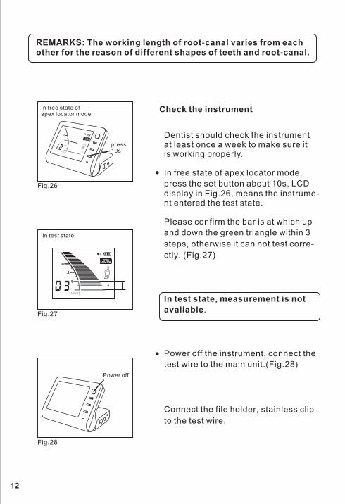
REMARKS: The working length of root canal varies from each
other for the reason
-
of different shapes of teeth and root-canal.
Check the instrument
Dentist should check the instrumentat least once a week to make sure itis working properly.
In free state of apex locator mode,
press the set button about s LCD
display in , means the instentered the test state.
Please confirm the bar is at which up
and down the green triangle within
steps otherwise it can not test corre
ctly
Power off the instrument, connect the
test wire to the main unit.
Connect the file holder stainless clip
to the test wire
10 ,
3
, -
.
.
,
.
rume-nt
In test state, measurement is not
available
Fig.26
(Fig.27
(Fig.28
)
)
Fig.26
press10s
In free state ofapex locator mode
In statetest
Power off
12
Fig.27
Fig.28

Precautions for Apex Locator Use
. ,
.
.
.
.
. .
.
.
. -
. -
, .
To ensure that short circuits do not impair the measurements be
particularly careful with patients fitted with metal crowns or bridges
Avoid excessive liquids inside the tooth cavity to prevent overflow
and incorrect measurements.
Make sure that the canal is wet enough to ensure reliability of the
measurement
Ensure that the file does not touch another instrument
Measurements in canals with open apex may provide results with
reduced precision
The result of measurement is for reference only, dentist should che
ck by X-ray film.
Sometimes, bars will unusually shake in the moment of the file inse
rted into the root canal, and when the file tip moved in the direction
of apex the result will get right
13
Fig.30
Contact with the file holder and stain
less clip, Fig. Confirm all the bars
displayed on screen and the green tr-
iangle is flashing Fig.
-
( 29)
. ( 30).
Fig.29

How to use your pulp tester
Preparation
1) Disconnect the charger from the
instrument if connected.
2) Connect the test handle and switchon the instrument, two tones audiosignal are emitted when the unit is
turned on
(Fig.31
(Fig.32
)
).
Fig.31
Fig.32
14
di didi di
press
X
Fig.33
ars, appear indicates that the
3) Switch to pulp tester mode by succ-essive presses on the MODE SWIT-
CH button visual information appe-,
pulp tester is ready for use (Fig.33).

' ;
.
4) Link the lip clip to the patient s lip
instead the patient may hold the lip clip
firmly in the hand
5) Insert the tooth probe into the handle.
(Fig.34
(Fig.35
)
)
Fig.35
15
Fig.34
Note: no other specific adjustment is necessary before
commencing test.

Getting Started
1) Clean and dry the tooth to be tested
2) To improve contact between tooth and
toothpaste to the metal tip
3) Place the probe on the middle of the
Avoid soft tissue and restorations such
.
.
,
. ,
.
, .
.
5
,
.
, . 50-80,
. 80, .
probe apply a little prophy
paste or
labial or lingual surface of the
tooth as crowns amalga-
ms or composites
4) When the probe contact tooth unquestionable, the unit activated
automatically. The number will indicate that an increasing Gentle-
Pulse stimulus is being applied to the tooth.
5) When the patient feels the stimulus leave the probe from the tooth
The stimulus will stop immediately The display will flash and hold
the final reading for approximately seconds, so it can be noted,
at this time contact tooth again the unit will apply stimulus contin-
uative After 5 seconds the unit will automatically turn to ready stat-
us.
6) During 20-50 beeper emits tone slowly During emits tone
faster After emits a f toneastest
16

Clinical Observations:
1) The reading corresponding to the
stimulus is 1-99, is estimated
that the tooth is vital Fig.36
2) No sensation at the maximum stimu-lus (--) suggests that the tooth is non
-vital This conclusion should be co-
nfirmed by thermal testing.
3) Generally incisors have similar thr-
olds about 10 premolars a-
bout molars about 35
4) Molars generally require greater sti-
lus than premolars but the thres-
may also be affected by such f -
ctors as the age of the patient trau-
pathology
–
( ).
,
,
30,
25 45, 70.
,
,
.
n
ormal
Fig.37
esh
mu
hold a
ma and
( )
–
– –
Fig.36
Fig.37
17
Automatic Shutdown
C-Root I (VI) automatically shuts down after 3 minutes without use.
It is advisable, however, to manually switch off instrument after worki-
ng by simply press the POWER button.

Troubleshooting
If the equipment is not normal work, before call our after-sales center,
please check the table below
Phenomenon Reason analyses Problem shooting
Can t power on'
Is battery installed
properly?Check the battery
Low battery? Charge the battery
Is the charger is con-nected to main unit?
Remove the chargerplug from main unit
Can t measure-
ment the lengthof canal
' Is all the connectionreliable?
Is test wire in good
state?
Check the connection
Check the test wire
No alarmIs volume in mute
condition?Turn on the sound
Can t set
memory bar
' Is instrument infree state?
Can t set flash
bar
'
The memory bar can be set only
by measurement state.
Instrument is inmeasurement state?
The flash bar can be
set only by free state.
Inaccurateapex value
The unit is in unstablecondition
Bad condition in rootcanal
Check the unit andcompare with X-ray film.
Clean the liquid andremnant
Electromagneticinterference
Don t use other
electronic equipment
'
Canal LengthIndicatoroverreacts or istoo sensitive.
Measurements
are too short.Poor accuracy.Erratic results.)
(
Is blood or salivaoverflowingfrom the opening ofthe crown?
If blood or other fluids overflow thecanal, the current will leak to the g-ums and the meter will jump to Ap-ex. Clean the canal, canal openingand tooth crown thoroughly.
Is the root canal filledwith blood, saliva orchemical solutions?
The canal length indicator bar maysuddenly swing when it breaks thesurface of fluids inside the rootcanal, but it will return to normal asit approaches the apex
18
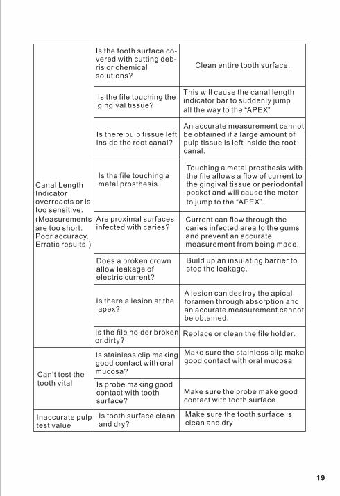
Canal LengthIndicatoroverreacts or istoo sensitive.
Measurements
are too short.Poor accuracy.Erratic results.)
(
Is the tooth surface co-vered with cutting deb-ris or chemicalsolutions?
Clean entire tooth surface.
Is the file touching thegingival tissue?
This will cause the canal lengthindicator bar to suddenly jump
all the way to the APEX“ ”
Is there pulp tissue leftinside the root canal?
An accurate measurement cannotbe obtained if a large amount ofpulp tissue is left inside the rootcanal.
Is the file touching ametal prosthesis
Touching a metal prosthesis withthe file allows a flow of current tothe gingival tissue or periodontalpocket and will cause the meter
to jump to the APEX“ ”.
Are proximal surfacesinfected with caries?
Current can flow through thecaries infected area to the gumsand prevent an accuratemeasurement from being made.
Does a broken crownallow leakage ofelectric current?
Build up an insulating barrier tostop the leakage.
Is there a lesion at theapex?
A lesion can destroy the apicalforamen through absorption andan accurate measurement cannotbe obtained.
Is the file holder brokenor dirty?
Replace or clean the file holder.
Can t test the
tooth vital
'
Inaccurate pulptest value
Is stainless clip makinggood contact with oralmucosa?
Is probe making goodcontact with toothsurface?
Make sure the stainless clip makegood contact with oral mucosa
Make sure the probe make goodcontact with tooth surface
Is tooth surface cleanand dry?
Make sure the tooth surface isclean and dry
19

Service and Maintenance
Guarantee
'
'
)
( 134
The instrument doesn t contain user serviceable parts. The service
and repair should be provided by trained service personnel only.
The instrument may be cleaned with a damp cloth and wiped with a
cold sterilant. Use of chemical agents may cause damage to the
instrument.
The measuring wire and test handle can t be autoclaved.
The accessories (lip clip, file holder, tooth probe can be sterilized
between treatments by autoclave at C).
C-Root I (VI) main unit is guaranteed for 24 months from the date of
purchase. The accessories (wire, battery etc.) are guaranteed for 6 mo-
nths.
The guarantee is valid for normal usage conditions. Any modificat-
ion or accidental damage will render the guarantee void.
We will repair or replace, at its option, a defective unit. This warran-
ty is in lieu of all warranties of merchantability, fitness for purpose or ot-
her warranties express or implied. We do not accept liability for any loss
or damage, direct, consequential or otherwise, arising out of the use of
or the inability to use the product herein described.
Note: autoclaving does not remove debris that may haveaccumulated. To assure adequate sterilization, washthe autoclavable components in warm, soapy water(before autoclaving).
20

Technical Specifications
Standard symbols
C-Root I (VI) belongs to following category of medical devices:
Type of screen: liquid crystalSupply: Li-ion 7.4 V batteryExternal charger: Input : AC100-240V 50/60 Hz or 220V /50 Hz
Output: DC 10V 1.5A
-
-
Internally powered equipment (7.4 V Li-ion rechargeable battery)
Type LF (Low Frequency) applied parts
Not suitable for use in the presence of flammable anaesthetic mixtur-
es with air or with oxygen or nitrous oxide
Continuous operation
Ingress of liquids not protected
Environmental conditions during transportation:
temperature: 20 C to +60 C to F)
relative humidity: 10% to 90%, non-condensing
On the instrument or external charger label appear standard
symbols as follows
Class II equipment
Type B applied part
Attention, consult accompanying documents
Direct current
Certified to MDD93/42/EEC
WEEE
-
-
-
-
(0 140
:
–
–
Technical specifications
21

Ver1.0
Foshan COXO Medical Instrument Co. Ltd
Address: 21 Wufeng Si Road, Foshan, Guangdong China
,
,
Wellkang Ltd.
Address: Suite B, 29 Harley Street London W1G QR
United Kingdom
, ,9


![· cantaluppi oreste colombo stefano botta christian grassi andrea mai-darell] dario lijppi massimo redaecli gianluca cat. vi vi vi vi vi vi vi vi vi vi vi vi vi vi vi vi vi vi vi](https://img.dokumen.tips/doc/110x75/5c69360d09d3f242168cb2b8/-cantaluppi-oreste-colombo-stefano-botta-christian-grassi-andrea-mai-darell.jpg)