Embed Size (px)
Citation preview
C 200 HC 200 HIC 200 H x4C 250 HC 250 HIC 250 HI LEC 250 H x4C 250 H x4 LE
OPERATOR’SMANUAL
ENGLISHOriginal Manual


AUSA Forklift Truck
C 200 H C 200 HI C 200 H x4 C 250 H C 250 HI C 250 HI LE C 250 H x4 C 250 HI x4 LE
Above chassis number 206 62866
ORIGINAL MANUAL


C200H-HI / C200H x4 / C250H-HIC250HI LE / C250H x4 / C250H x4 LE 3
Thank you for choosing this AUSA forklift truck (hereinafter forklift). The purpose of this Operators and Safety Manual is to provide you, the user, with instructions concerning the productive, safe and efficient use of this forklift. You should read and understand this manual before operating the forklift. The Manual contains safety messages concerning the use of the forklift. Remember that “you” are the key to safety.
The preservation of these qualities over a long period of time is in your hands. The correct use of your forklift will allow you to make the most of the resultant benefits.
The Operator’s and Safety Manual also contains instructions for some adjustments and for maintenance of this fork-lift. Follow these instructions carefully while performing routine maintenance checks and keep a record of all maintenance. As wide variations in operating conditions may be experienced, you are urged to contact your AUSA Distributor to resolve any operational or service problems.
Please have all operators of this forklift read and understand this Operator’s and Safety Manual.
Any damage resulting from the incorrect use of the forklift shall not be considered to be the responsibility of AUSA. In the event of query, complaint or to place an order for spares, please contact your Official AUSA Dealer.
This forklift is designed and intended for off highway use. If it is temporarily operated on any public street or highway, the state and local laws governing speed, size, weight, brakes and lighting must be complied with.
For further information you may write, FAX or E-mail to:
AUSA Center, S.L.U.Apartado P.O.B. 194
08243 MANRESA (Barcelona) SPAINTel. 34- 93 874 75 52 / 93 874 73 11
Fax 34- 93 873 61 39 / 93 874 12 11 / 93 874 12 55E-mail: [email protected]
Web: http://www.ausa.com
AUSA is continuously trying to improve the efficiency, productivity and safety of its products and reserves the right to make such improvements without incurring any obligation to make changes to forklifts previously sold. Because of this policy of striving for constant product improvement, the specifications and operating instructions shown in this Operator’s and Safety Manual may be different from prior forklift models. As such, we will not accept claims that are based on the data, illustrations or descriptions included in these instructions.
Only original AUSA spare parts should be used. This is the only way to guarantee that AUSA machinery has the same operational level as at the time of delivery. No alterations should be made to the forklift without the prior authorization of the manufacturer.
When not in use keep it stored on the forklift in the Manual holder box in the engine’s compartment in the control valve support (fig. 1).
(fig.
1)
Foreword
M O P 1 0 0 9 1 0 0 2

C200H-HI / C200H x4 / C250H-HIC250HI LE / C250H x4 / C250H x4 LE4
Index Uses and improper Uses of the forklift ................................................................... 5
Identification of the forklift components ................................................................. 6
Vehicle Identification and Serial Numbers .............................................................. 7
Technical Specifications .......................................................................................... 8
Decals / labels / identification plates all markets (except USA) ............................ 22
Decals / labels / identification plates (USA Market) ............................................... 34
Controls and instruments ........................................................................................ 48
Instrument Panel and controls ................................................................................ 51
Operating the forklift ................................................................................................ 57
Special procedures ................................................................................................. 61
Special Safety Messages ........................................................................................ 64
Parking the machine ............................................................................................... 72
Transporting the machine ....................................................................................... 73
Recommended fluids and lubricants ...................................................................... 76
Maintenance Chart .................................................................................................. 78
Periodic Maintenance Operations ........................................................................... 80
Hydrostatic transmission error conditions ............................................................. 100
Electric circuit .......................................................................................................... 102
Electric circuitC200H / C200HI / C200H x4 / C250HI LE / C250H x4 LE ................................ 103
Electric wiringC200H / C200HI / C200H x4 / C250HI LE / C250H x4 LE ................................ 107
Electric circuitC250H / C250HI / C250H x4 ............................................................................. 108
Electric wiringC250H / C250HI / C250H x4 ............................................................................. 113
Hydraulic diagram (Hydraulic appliances) ............................................................. 114
Hydraulic diagram (Transmission)C200H / C200HI / C200H x4 / C250HI LE / C250H x4 LE ................................ 115
Hydraulic diagram (Transmission)C250H / C250HI / C250H x4 ............................................................................. 116
Transmission Troubleshooting ................................................................................ 117
EC Certificate of Conformity .................................................................................... 118

C200H-HI / C200H x4 / C250H-HIC250HI LE / C250H x4 / C250H x4 LE 5
Uses for which the forklift is designedForklifts C200H-HI / C250H x4 / C250H-HI / C250H x4 / C250HI LE / C250HI X4 LE have been designed and manufactured for lifting, handling and transporting loads on rough ground and industrial use. The safety of individuals and of the loads carried must be ensured through the use of forks or other accessories and equipment.
ROUGH TERRAIN USE (C200/250H)This forklift truck is designed for transporting and lifting loads on grounds not in good condition, roughly flat, not too steep slopes and small obstacles, so that the stability conditions are not optimal.
INDUSTRIAL USE (C200/250HI)This forklift truck is designed for transporting and lifting loads on good condition floors, that means flat, levelled and paved ground, so that there are optimal stability conditions.
Any use other than that described above shall be considered inappropriate and therefore improper.Strict adherence to the operating, maintenance and repair conditions specified by the manufacturer are essential in order to maintain the forklift in good working order.Driving, maintenance and repair of the forklift should only be carried out by suitably qualified personnel, with the necessary tools and knowledge of the control and safety procedures relative to the forklift. When handling loads or carrying out maintenance and/or repair work, the occupational health and safety regulations, together with those relative to accident prevention, should be observed.When driving with the forklift on public highways, special care should be taken to ensure compliance with the current legislation for this type of vehicle (Highway Code).AUSA does not assume responsibility for any damage resulting from modifications made to the forklift without express authorization.
The texts following this symbol provide information on recycling and protecting the environment.
Improper useImproper use is understood to mean the use of the forklift in a manner not in keeping with the criteria and instructions given in this Operator’s and Safety Manual and in a way which might cause damage to persons or objects.Some of the more common and dangerous examples of improper use are given below:
- Carrying persons other than the operator on the forklift.- Not strictly observing the instructions for use and maintenance given in this
Operator’s and Safety Manual.- Exceeding the limits for load and centre of gravity given in the relevant load
charts.- Working on unstable, unshared grounds or at the edges of trenches and ditches.- Working on excessively steep slopes.- The use of accessories or equipment for purposes other than those for which
they have been designed.- The use of accessories or equipment not manufactured or authorized by AUSA.
Uses and improperUses of the forklift

C200H-HI / C200H x4 / C250H-HIC250HI LE / C250H x4 / C250H x4 LE6
Term such as right, left, front and rear when used in this Operator’s and Safety Manual indicate the right and left sides of the machine, the front and back of the machine, as viewed from the operators seat looking forward.
Identification components1- Overhead guard.2- Driving and load control (Joystick)3- Parking brake switch.4- Driver seat with seat belt.5- Diesel tank.6- Hydraulic tank.7- Forks.8- Lifting mast.9- Rotating beacon.10- Lighting equipment ().11- Rear-view mirror.
Identification of the forklift
components1
3
2
4
10
8
6 5
11
9 10
7

C200H-HI / C200H x4 / C250H-HIC250HI LE / C250H x4 / C250H x4 LE 7
¡Important! Write your machine Model number, date of sale, chassis and engine serial number in the spaces provided below. Give this information to your AUSA dealer when you need parts or information for your machine. Make a record of these numbers in your files.
Model number: .....................................................................
Date of sale: .........................................................................
Chassis serial number: ........................................................
Engine serial number: ..........................................................
The Vehicle Identification Plate is located at the left of the operators seat (fig. 1). The Engine Serial Number is located on the left side of the engine (fig. 3-4). The Chassis Serial Number is located on the right side of the chassis (fig. 2).
Principals components of identification platesThe plates of every components not built directly by AUSA, (for example: engines, pumps, etc.) are directly applied on the same components, in points where the respective makers put them originally.
(fig.
3 -
ISU
ZU 4
LE2)
(fig.
4 –
KU
BO
TA V
2403
-M)
(fig.
2)
(fig.
1)
Vehicle Identification
and Serial Numbers

C200H-HI / C200H x4 / C250H-HIC250HI LE / C250H x4 / C250H x4 LE8
Dimensions (in)
A B C D
E
F G I J K Lnarrow version
wideversion
C 200 H COMPACT 6ft 7.1in 8.1in 11.6in 4ft 5.5in 4ft 6.1in - R 9ft 2.2in 8ft 6.4in 4in 1.6in 2ft 13ft 11in
C 200 HC 200 HI C 250 HI LE
6ft 8.7in 9.6in 12.2in 4ft 6.1in 4ft 9.5in 5ft 10in R 9ft 2.2in 8ft 6.4in 4in 1.6in 2ft 13ft 11in
C 200 H x4C 250 H x4 LE 6ft 9.9in 10.6in 12.2in 4ft 6.8in 4ft 9.5in 5ft 10in R 14ft 5.2in 9ft 6.2in 4in 1.6in 2ft 13ft 11in
C 250 HC 250 HI 7ft 0.6in 11in 15.3in 4ft 6.1in 4ft 11.5in 5ft 11.2in R 9ft 2.2in 8ft 6.4in 5.1in 1.8in 2.01ft 13ft 11.1in
C 250 H x4 6ft 11.5in 12.6in 15.3in 4ft 6.8in 4ft 11.5in 5ft 11.2in R 14ft 5.2in 9ft 6.2in 5.1in 1.8in 2.01ft 13ft 11.1in
Dimensions (mm)
A B C D
E
F G I J K Lnarrow version
wideversion
C 200 H COMPACT 2010 205 295 1360 1375 - R 2800 2600 100 40 610 4240
C 200 HC 200 HI C 250 HI LE
2050 245 310 1375 1460 1782 R 2800 2600 100 40 610 4240
C 200 H x4C 250 H x4 LE 2080 270 310 1392 1460 1782 R 4400 2900 100 40 610 4240
C 250 HC 250 HI 2150 280 390 1375 1510 1810 R 2800 2600 130 45 615 4245
C 250 H x4 2120 320 390 1392 1510 1810 R 4400 2900 130 45 615 4245
Technical Specifications

C200H-HI / C200H x4 / C250H-HIC250HI LE / C250H x4 / C250H x4 LE 9
Mast chart (in)
Type ofmast
Max.liftingheight(ft in)
Front axleFreelift
(ft in)
Machine height with mast retracted(ft in)
Machine height with mast extended(ft in)
Pay Load (lb.) at maximum height.Load center at 24 in (600 mm) (USA)
C200HCOMPACT
C200HC200HIC200Hx4C250HI LEC250Hx4 LE
C250HC250HIC250Hx4
C200HCOMPACT
C200HC200HIC200Hx4C250HI LEC250Hx4 LE
C250HC250HIC250Hx4
C200HCOMPACT (narrow
axle)
C200H (narrow
axle)
C200H (wideaxle)
C200HI (narrow
axle)
C250H (narrow
axle)
C250H (wideaxle)
C250HI (narrow
axle)
Duplex (Std.)
10ft 10inNarrow /
Wide (op.)4.7in - 7ft 10.3in 8ft 0.9in - 13ft 7.4in 13ft 10in - 4040 4040 4040 5060 5060 5060
Duplex 8ft 6inNarrow /
Wide (op.)4.7in 6ft 7.7in 6ft 8.5in 6ft 11in 7ft 11.7in 11ft 3.9in 11ft 6.4in 4040 4040 4040 4040 5060 5060 5060
Duplex 11ft 10inNarrow /
Wide (op.)4.7in - 8ft 4.2in 8ft 6.8in - 14ft 7.2in 14ft 9.8in - 4040 4040 4040 4650 4850 5060
Duplex 14ft 9inWide /
Narrow (HI)4.7in - 9ft 9.9in 10ft 0.5in - 17ft 6.6in 17ft 9.2in - - 3640 3640 - 4250 5060
Triplex(free lift)
12ft 2inNarrow /
Wide (op.)4ft 4in 6ft 7.7in 6ft 8.5in 8ft 11.5in 15ft 15ft 0.7in 15ft 3.7in 4040 3640 4040 4040 4450 4650 5060
Triplex(free lift)
14ft 1inWide /
Narrow (HI)4ft 4in - 7ft 4.5in 7ft 7.5in - 17ft 2in 17ft 5in - - 3640 3640 - 4250 5060
Triplex(free lift)
17ft 8inNarrow /
Wide (op.)5ft 6in - 8ft 6.8in 8ft 9.7in - 20ft 7.8in 20ft 11in - - 2220 3440 - 2220 4430
Mast chart (mm)
Type ofmast
Max.liftingheight(mm)
Front axleFreelift
(mm)
Machine height with mast retracted(mm)
Machine height with mast extended(mm) Pay Load (Kg.) at maximum height
C200HCOMPACT
C200HC200HIC200Hx4C250HI LEC250Hx4 LE
C250HC250HIC250Hx4
C200HCOMPACT
C200HC200HIC200Hx4C250HI LEC250Hx4 LE
C250HC250HIC250Hx4
C200HCOMPACT (narrow
axle)
C200H (narrow
axle)
C200H (wideaxle)
C200HI (narrow
axle)
C250H (narrow
axle)
C250H (wideaxle)
C250HI (narrow
axle)
Duplex (Std.)
3300Narrow /
Wide (op.)120 - 2395 2460 - 4150 4215 - 2000 2000 2000 2500 2500 2500
Duplex 2600Narrow /
Wide (op.)120 2025 2045 2110 2430 3450 3515 2000 2000 2000 2000 2500 2500 2500
Duplex 3600Narrow /
Wide (op.)120 - 2545 2610 - 4450 4515 - 2000 2000 2000 2300 2400 2500
Duplex 4500Wide /
Narrow (HI)120 - 2995 3060 - 5350 5415 - - 1800 1800 - 2100 2500
Triplex(free lift)
3700Narrow /
Wide (op.)1130 2025 2045 2120 4570 4590 4665 2000 1800 2000 2000 2200 2300 2500
Triplex(free lift)
4300Wide /
Narrow (HI)1330 - 2245 2320 - 5230 5300 - - 1800 1800 - 2100 2500
Triplex(free lift)
5400Narrow /
Wide (op.)1680 - 2610 2685 - 6295 6370 - - 1100 1700 - 1100 2200
Technical Specifications

C200H-HI / C200H x4 / C250H-HIC250HI LE / C250H x4 / C250H x4 LE10
Diesel engineFour cylinders, four strokes, water-cooled. Electric starter. Mixed radiator (water/oil).
C 200 H-HI / C 200 H x4 / C 250 HI LE / C 250 HI x4 LE: Isuzu 4LE2- Tier II. Power 45.92 HP (33.8 kw at 2,700 rpm in accordance with SAE J 1349 Norm).C 250 H-HI / C 250 H x4: KUBOTA V2403-M – E3B.Power 49.6 HP (36.5 kw at 2,600 rpm in accordance with SAE J 1995 Norm).
See the engine instructions handbook.
TransmissionHydrostatic system with variable flow pump and inching. Electronic control on C 250 H-HI / C 250 H x4 models.
C 200 H-HI / C 200 H x4 / C 250 HI LE / C 250 HI x4 LE: Hydrostatic motor with two speeds selected by electrical switch. Maximum operating pressure: 4,713 PSI (325 bar).C 250 H-HI / C 250 H x4: Hydrostatic motor with variable flow. Maximum operating pressure: 6,091 PSI (420 bar)
Both models with 2 wheel drive version (2WD) and 4 wheel drive version (4WD).
Permanent 4WD with COMPEN® System in Standard Machine4x4 connectable on demand with “Full grip system®” ()
Directional control The selection of the drive (forwards/ backwards) is made using a switch on the lower part of the joystick. A lamp in the shape of an arrow lights up on the top of it when a movement mode is selected.
SteeringHydr aulic powered with one double acting hydraulic cylinder on the rear axle.Working pressure (all models): 2320 PSI (160 bar).
Wheels
Dimensions:
Dimensions
Front wheels Rear wheels
C 200 H COMPACT 10.0 / 75 - 15,3 (14 PR) 6.50 - 10 (10 PR)
C 200 H 11.5 / 80 - 15,3 (14 PR) 7.00 - 12 (12 PR)
C 200 HI 11.5 / 80 - 15,3 (14 PR) 7.00 - 12 (12 PR)
C 200 H x4 11.5 / 80 - 15,3 (14 PR) 27 x 10 - 12 (14 PR)
C 250 H 12.5 / 80 - 18 (12 PR) 7.00 - 12 (12 PR)
C 250 HI 12.5 / 80 - 18 (12 PR) 7.00 - 12 (12 PR)
C 250 H x4 12.5 / 80 - 18 (12 PR) 10.0 / 75 - 15,3 (10 PR)
C 250 HI LE 12.5 / 80 - 18 (12 PR) 7.00 - 12 (12 PR)
C 250 H x4 LE 12.5 / 80 - 18 (12 PR) 10.0 / 75 - 15,3 (10 PR)
Technical Specifications
C200H-HI / C200H x4 / C250H-HIC250HI LE / C250H x4 / C250H x4 LE 11
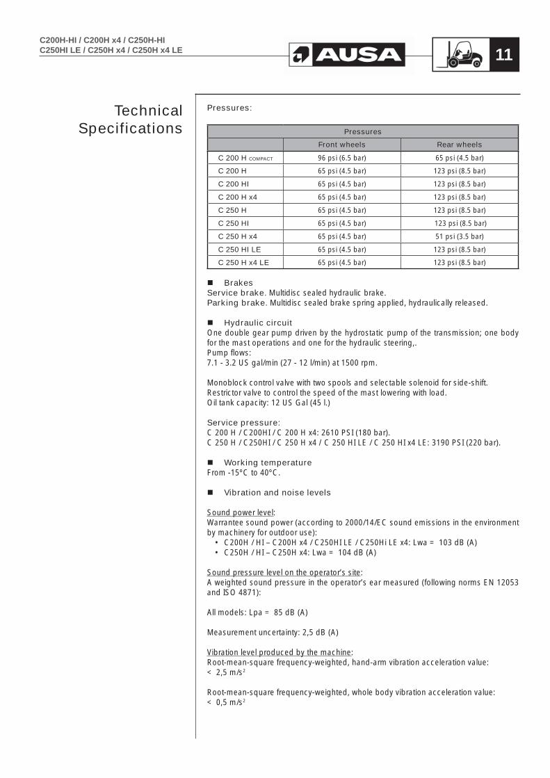
Pressures:
Pressures
Front wheels Rear wheels
C 200 H COMPACT 96 psi (6.5 bar) 65 psi (4.5 bar)
C 200 H 65 psi (4.5 bar) 123 psi (8.5 bar)
C 200 HI 65 psi (4.5 bar) 123 psi (8.5 bar)
C 200 H x4 65 psi (4.5 bar) 123 psi (8.5 bar)
C 250 H 65 psi (4.5 bar) 123 psi (8.5 bar)
C 250 HI 65 psi (4.5 bar) 123 psi (8.5 bar)
C 250 H x4 65 psi (4.5 bar) 51 psi (3.5 bar)
C 250 HI LE 65 psi (4.5 bar) 123 psi (8.5 bar)
C 250 H x4 LE 65 psi (4.5 bar) 123 psi (8.5 bar)
BrakesService brake. Multidisc sealed hydraulic brake.Parking brake. Multidisc sealed brake spring applied, hydraulically released.
Hydraulic circuitOne double gear pump driven by the hydrostatic pump of the transmission; one body for the mast operations and one for the hydraulic steering,.Pump flows:7.1 - 3.2 US gal/min (27 - 12 l/min) at 1500 rpm.
Monoblock control valve with two spools and selectable solenoid for side-shift.Restrictor valve to control the speed of the mast lowering with load.Oil tank capacity: 12 US Gal (45 l.)
Service pressure:C 200 H / C200HI / C 200 H x4: 2610 PSI (180 bar).C 250 H / C250HI / C 250 H x4 / C 250 HI LE / C 250 HI x4 LE: 3190 PSI (220 bar).
Working temperatureFrom -15ºC to 40ºC.
Vibration and noise levels
Sound power level:Warrantee sound power (according to 2000/14/EC sound emissions in the environment by machinery for outdoor use):
• C200H / HI – C200H x4 / C250HI LE / C250Hi LE x4: Lwa = 103 dB (A) • C250H / HI – C250H x4: Lwa = 104 dB (A)
Sound pressure level on the operator’s site:A weighted sound pressure in the operator’s ear measured (following norms EN 12053 and ISO 4871):
All models: Lpa = 85 dB (A)
Measurement uncertainty: 2,5 dB (A)
Vibration level produced by the machine:Root-mean-square frequency-weighted, hand-arm vibration acceleration value: < 2,5 m/s2
Root-mean-square frequency-weighted, whole body vibration acceleration value: < 0,5 m/s2
Technical Specifications

C200H-HI / C200H x4 / C250H-HIC250HI LE / C250H x4 / C250H x4 LE12
Electrical equipmentElectrical starter 2,0 Kw. Pre-heating spark plugs. Alternator of 35A (Isuzu Engine) and 480W (Kubota Engine). Battery 12V- 70 AH. Horn. Rotating beacon. Back-up alarm. Engine oil pressure alarm. Hydraulic oil level alarm. Coolant temperature alarm.
WeightsUnladen weight (with full tanks):C 200 H-HI: 4200 kg (9,259 lbs). C 200 H x4: 4200 kg (9,259 lbs).C 250 H-HI: 4400 kg (9,700 lbs). C 250 H x4: 4400 kg (9,700 lbs)C 250 H x4 LE: 4400 kg (9,700 lbs). C 250 HI x4 LE: 4400 kg (9,700 lbs). (The Compact machine has the same weight than the C 200 H-HI).
Unladen weight (with full tanks):C 200 H-HI: 6200 kg (13,668 lbs). C 200 H x4: 6200 kg (13,668 lbs).C 250 H-HI: 6900 kg (15,211 lbs). C 250 H x4: 6900 kg (15,211 lbs)C 250 H x4 LE: 6900 kg (15,211 lbs). C 250 HI x4 LE: 6900 kg (15,211 lbs).
(The Compact machine has the same weight than the C 200 H-HI).
Load Capacity With the load center of the load at 500 mm. (see LOAD CHARTS In this manual)C 200 H-HI / C 200 H x4: 2.000 Kg; C 250 H-HI / C 250 H x4 / C 250 H x4 LE / C 250 HI x4 LE: 2.500 Kg.With the load center at 24 inches (600 mm) (see LOAD CHARTS In this manual)C 200 H-HI / C 200 H x4: 4040 lbs (1835 Kg).C 250 H-HI / C 250 H x4 / C 250 H x4 LE / C 250 HI x4 LE: 5060 lbs (2294 Kg).
Fork carriageClass: FEM/ISO 2.
Standard mastSide-shift 47 in. (1200 mm ) widthLifting height: 10ft. 10in. (3,30 m).Free litf: 6 inches (150 mm).Forks length: 47 inches (1200 mm).
Lifting speed Without load: 103 ft/min (0,526 m./sec). with load: 101 ft/min (0,513 m./sec).
Lowering speed Without load: 81 ft/min. (0,412 m./sec). With load: 125 ft/min (0,637 m./sec).
WARNINGThis forklift is not designed to travel with elevated load or with the mast tilted forward.Do not tilt forward the mast with the forks elevated except to pick up or deposit the load.
Technical Specifications

C200H-HI / C200H x4 / C250H-HIC250HI LE / C250H x4 / C250H x4 LE 13
Control panelThe controls, switches and warning lights are integrated in the steering column and below the joystick.
Lighting ()Work lighting equipment, steering indicators, parking lights and warning.
Overhead guardManufactured according with ISO 3449 and ISO 3471 / ASME B56.6.
WARNINGThe operator is protected by an overhead guard which complies with the ISO 3449 and ISO 3471 / ASME B56.6 standards. It provides protection against falling objects and together with the mast, provides protection should the forklift overturn. The seat belt is an important part of the safety system and should always be fastened before starting to operate the forklift. In the event of the forklift overturning, if the seat belt is not fastened the operator may suffer serious injury or even loss of life as a result of crushing from the forklift or even the overhead guard itself.
Aisle widthsSee graph.
Technical Specifications

14C200H-HI / C200H x4 / C250H-HI
C250HI LE / C250H x4 / C250H x4 LE
ROUGH TERRAIN USE (C200H / C250H)This forklift truck is designed for transporting and lifting loads on grounds not in good condition, roughly flat, not too steep slopes and small obstacles, so that the stability conditions are not optimal.
Load charts for C200H / C200H x4 with wide axle (500 mm. load centre)
Load charts for C200H / C200H x4 with wide axle (24 in. load centre)
08243 MANRESA (SPAIN)43.01350.28
AUSA Center, S.L.U.
D = Load center extension from face of forks
D inches 24 28 32 36 40 44 48
D
G
G LBS
MAXIMUM FORKLIFT LOADON LEVEL SURFACE
MODEL C200H / C200H x4
4040
3740
3470
32403040
28612700
8ft 6in10ft 10in11ft 10in12ft 2in
08243 MANRESA (SPAIN)43.01350.28
AUSA Center, S.L.U.
D = Load center extension from face of forks
D inches 24 28 32 36 40 44 48
D
G
G LBS
MAXIMUM FORKLIFT LOADON LEVEL SURFACE
MODEL C200H / C200H x4
3640
3360
3120
29202740
25702430
14ft 1in14ft 9in
08243 MANRESA (SPAIN)43.01350.28
AUSA Center, S.L.U.
D = Load center extension from face of forks
D inches 24 28 32 36 40 44 48
D
G
G LBS
MAXIMUM FORKLIFT LOADON LEVEL SURFACE
MODEL C200H / C200H x4
2220
2050
1910
17801670
15651490
17ft 8in
15C200H-HI / C200H x4 / C250H-HIC250HI LE / C250H x4 / C250H x4 LE
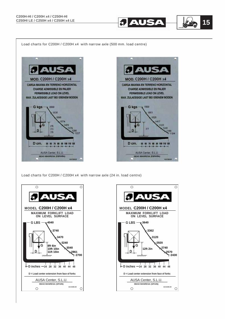
Load charts for C200H / C200H x4 with narrow axle (500 mm. load centre)
Load charts for C200H / C200H x4 with narrow axle (24 in. load centre)
08243 MANRESA (SPAIN)43.01350.28
AUSA Center, S.L.U.
D = Load center extension from face of forks
D inches 24 28 32 36 40 44 48
D
G
G LBS
MAXIMUM FORKLIFT LOADON LEVEL SURFACE
MODEL C200H / C200H x4
4040
3740
3470
32403040
28612700
8ft 6in10ft 10in11ft 10in
08243 MANRESA (SPAIN)43.01350.28
AUSA Center, S.L.U.
D = Load center extension from face of forks
D inches 24 28 32 36 40 44 48
D
G
G LBS
MAXIMUM FORKLIFT LOADON LEVEL SURFACE
MODEL C200H / C200H x4
3640
3362
3120
29202740
25702430
12ft 2in

16C200H-HI / C200H x4 / C250H-HI
C250HI LE / C250H x4 / C250H x4 LE
Load charts for C250H / C250H x4 / C250H x4 LE with wide axle (500 mm. load centre)
Load charts for C250H / C250H x4 / C250H x4 LE with wide axle (24 in. load centre)
08243 MANRESA (SPAIN)43.01350.28
AUSA Center, S.L.U.
D = Load center extension from face of forks
D inches 24 28 32 36 40 44 48
D
G
G LBS
MAXIMUM FORKLIFT LOADON LEVEL SURFACE
MODEL C250H / C250H x4
5060
4670
4340
40603800
35803390
8ft 6in10ft 10in
08243 MANRESA (SPAIN)43.01350.28
AUSA Center, S.L.U.
D = Load center extension from face of forks
D inches 24 28 32 36 40 44 48
D
G
G LBS
MAXIMUM FORKLIFT LOADON LEVEL SURFACE
MODEL C250H / C250H x4
4850
4400
4170
38903650
34403250
11ft 10in
08243 MANRESA (SPAIN)43.01350.28
AUSA Center, S.L.U.
D = Load center extension from face of forks
D inches 24 28 32 36 40 44 48
D
G
G LBS
MAXIMUM FORKLIFT LOADON LEVEL SURFACE
MODEL C250H / C250H x4
4650
4300
3990
37303500
33003110
12ft 2in

17C200H-HI / C200H x4 / C250H-HIC250HI LE / C250H x4 / C250H x4 LE
Load charts for C250H / C250H x4 / C250H x4 LE with wide axle (500 mm. load centre)
Load charts for C250H / C250H x4 / C250H x4 LE with wide axle (24 in. load centre)
08243 MANRESA (SPAIN)43.01350.28
AUSA Center, S.L.U.
D = Load center extension from face of forks
D inches 24 28 32 36 40 44 48
D
G
G LBS
MAXIMUM FORKLIFT LOADON LEVEL SURFACE
MODEL C250H / C250H x4
14ft 1in14ft 9in
4250
3930
3650
34103200
30002840
08243 MANRESA (SPAIN)43.01350.28
AUSA Center, S.L.U.
D = Load center extension from face of forks
D inches 24 28 32 36 40 44 48
D
G
G LBS
MAXIMUM FORKLIFT LOADON LEVEL SURFACE
MODEL C250H / C250H x4
17ft 8in
2220
2050
1910
17801670
15751490

18C200H-HI / C200H x4 / C250H-HI
C250HI LE / C250H x4 / C250H x4 LE
Load charts for C250H / C250H x4 / C250H x4 LE with narrow axle (500 mm. load centre)
Load charts for C250H / C250H x4 / C250H x4 LE with narrow axle (24 in. load centre)

19C200H-HI / C200H x4 / C250H-HIC250HI LE / C250H x4 / C250H x4 LE
INDUSTRIAL USE (C200H / C250HI)This forklift truck is designed for transporting and lifting loads on good condition floors, that means flat, levelled and paved ground, so that there are optimal stability conditions.
Load charts for C200HI (500 mm. load centre)
Load charts for C200HI (24 in. load centre)
08243 MANRESA (SPAIN)43.01350.28
AUSA Center, S.L.U.
D = Load center extension from face of forks
D inches 24 28 32 36 40 44 48
D
G
G LBS
MAXIMUM FORKLIFT LOADON LEVEL SURFACE
MODEL C200HI
8ft 6in10ft 10in11ft 10in12ft 2in
4040
3740
3470
32403040
28612700
08243 MANRESA (SPAIN)43.01350.28
AUSA Center, S.L.U.
D = Load center extension from face of forks
D inches 24 28 32 36 40 44 48
D
G
G LBS
MAXIMUM FORKLIFT LOADON LEVEL SURFACE
MODEL C200HI
14ft 1in14ft 9in
3640
3350
3110
29102735
25802425
08243 MANRESA (SPAIN)43.01350.28
AUSA Center, S.L.U.
D = Load center extension from face of forks
D inches 24 28 32 36 40 44 48
D
G
G LBS
MAXIMUM FORKLIFT LOADON LEVEL SURFACE
MODEL C200HI
17ft 8in
3440
3175
2955
27552580
24252290
20C200H-HI / C200H x4 / C250H-HI
C250HI LE / C250H x4 / C250H x4 LE
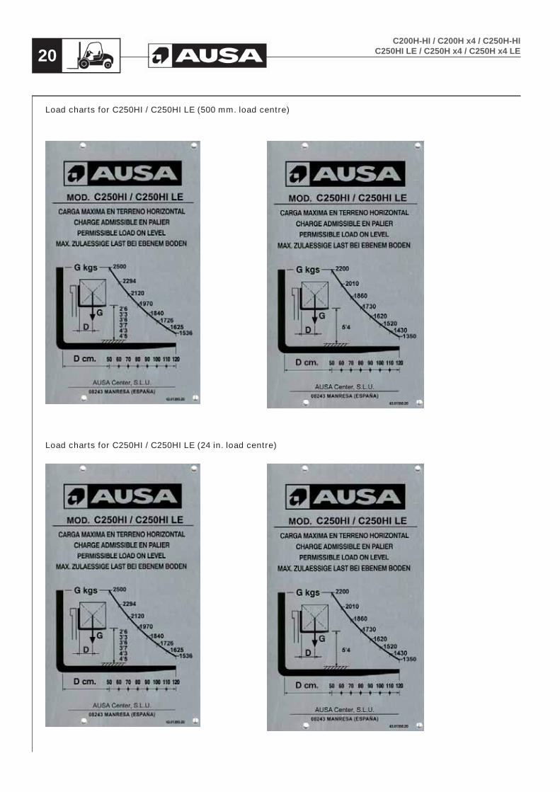
Load charts for C250HI / C250HI LE (500 mm. load centre)
Load charts for C250HI / C250HI LE (24 in. load centre)

C200H-HI / C200H x4 / C250H-HIC250HI LE / C250H x4 / C250H x4 LE 21
Optional equipmentOptional equipment is marked with an asterisk (). Optional equipment is only supplied at the express wish of the customer, for certain versions of forklift or even only in certain countries.
- 4 WD transmission engaged by demand (FULL GRIP®)- Partially closed cab (front and rear windshield).- Closed cab with heating (standard for USA market).- Hydraulic shovels: 14 cu.ft (400 l.) and 21 cu.ft (600 l.)- 8ft 6in (2600 mm), 11ft 10in (3600 mm) and 14ft 9in (4500 mm) maximum height
Duplex Mast- 12ft2in (3700 mm), 14ft 1in (4300 mm) and 17ft 8in (5400 mm) maximum
height Triplex mast (free lift)- 5ft 10in (1782 mm) and 5ft 11in (1810 mm) wide front axle (not available for the
C200H Compact model).- 4ft 9in (1450 mm) 4ft 11in (1510 mm) narrow axle - 63 in. (1600 mm) and 47 in. (1200 mm) width load backrest (standard for USA
market).- Electronic equipment anti-theft.- Oxi-catalytic exhaust purifier.- Exhaust Spark arrestor- Filter of gas-oil with water separator - Side-shift fork carriage 63 in. (1600 mm ) width- Super-elastic solid tyres.- Extra wide tyres.- Industrial use tyres- Lighting equipment (standard for USA market).- 4th hydraulic control for attachments
Where the forklift comes equipped with accessories mounted at factory, please read the relevant Instruction Manual for each accessory carefully before use. Each accessory has its own Instruction Manual issued by the manufacturer, and this is provided with the forklift Operator’s and Safety Manual.Where accessories and equipment are fitted to the basic chassis or fork carriage plate at a later date by companies other than the manufacturer, the specifications and limitations of the forklift with respect to weight and dimensions, the adjustment and effectiveness of the lighting system, the protective system requirements, or any additional systems required to guarantee vehicle safety should be taken into consideration.
Technical Specifications

22C200H-HI / C200H x4 / C250H-HI
C250HI LE / C250H x4 / C250H x4 LE
Decals / labels / identification plates all markets (except USA)
STICKER:JOYSTICK FUNCTION
REFERENCE:10.15003.01
DESCRIPTION:INDICATIVE STICKER 60X75
QUANTITY:1
POSITION:Stuck on the inside of the right front fender, in the top center position. Just above sticker ref. 10.15005.01, at 0.1969 in.
STICKER:JOYSTICK FUNCTION BUTTONS
REFERENCE:10.15005.01
DESCRIPTION:INDICATIVE STICKER MAST SIDE SHIFT
QUANTITY:1
POSITION:Stuck on the inside of the right front fender, in the top center position. Just above sticker ref. 10.15003.01, at 0.1969 in.
STICKER:JOYSTICK FUNCTION BUTTONS
REFERENCE:10.15009.00
DESCRIPTION:INDICATIVE STICKER AUXILIAR HYDRAULIC LINE ()
QUANTITY:1
POSITION:Stuck on the inside of the right front fender, in the top center position. Just above sticker ref. 10.15005.01, at 0.1969 in.

23C200H-HI / C200H x4 / C250H-HIC250HI LE / C250H x4 / C250H x4 LE
STICKER:JOYSTICK FUNCTION BUTTONS
REFERENCE:10.15011.00
DESCRIPTION:INDICATIVE STICKER 4WD CONNECTION ()
QUANTITY:1
POSITION:Stuck on the inside of the right front fender, in the top center position. Just above sticker ref. 10.15005.01 o 10.15009.00, at 0.1969 in.
STICKER:DANGEROUS AREA
REFERENCE:45.01352.00
DESCRIPTION:INDICATIVE STICKER
QUANTITY:2
POSITION:On both sides of the mast, above the beam, with its upper side aligned at 4ft 92 in from the ground, below the sticker ref. 13.12136.00 “AUSA Make”, and 0.3937 in away from it.
STICKER:TO HOIST MACHINE
REFERENCE:58.01353.01
DESCRIPTION:INDICATIVE STICKER 105X100
QUANTITY:1
POSITION:On the left side of the machine, at the lower exterior part of the front fender, aligned on its upper side with sticker 45.19101.00 “EC mark”.

24C200H-HI / C200H x4 / C250H-HI
C250HI LE / C250H x4 / C250H x4 LE
STICKER:AUSA
REFERENCE:13.12136.00
DESCRIPTION:AUSA STICKER
QUANTITY:2
POSITION:On both sides of the machine, at a distance of 0.984 in and a height of 1.969 in from the lower rear corner of each tank, aligned with the bottom of the tank.
STICKER:FRONT AXLE WHEELS INFLATED PRESSURE (Only on C200H compact)
REFERENCE:01.12107.00
DESCRIPTION:INDICATIVE STICKER 6,5 BAR / 96 PSI
QUANTITY:2
POSITION:On both sides of the machine, above the fenders of the front wheels, at the front outer end of the fenders, aligned with the outer edge.
STICKER:FRONT AXLE WHEELS INFLATED PRESSURE (ALL MODELS EXCEPT C200H compact)
REFERENCE:01.12105.01
DESCRIPTION:INDICATIVE STICKER 4,5 BAR / 66 PSI
QUANTITY:2
POSITION:On both sides of the machine, above the fenders of the front wheels, at the front outer end of the fenders, aligned with the outer edge.
25C200H-HI / C200H x4 / C250H-HIC250HI LE / C250H x4 / C250H x4 LE
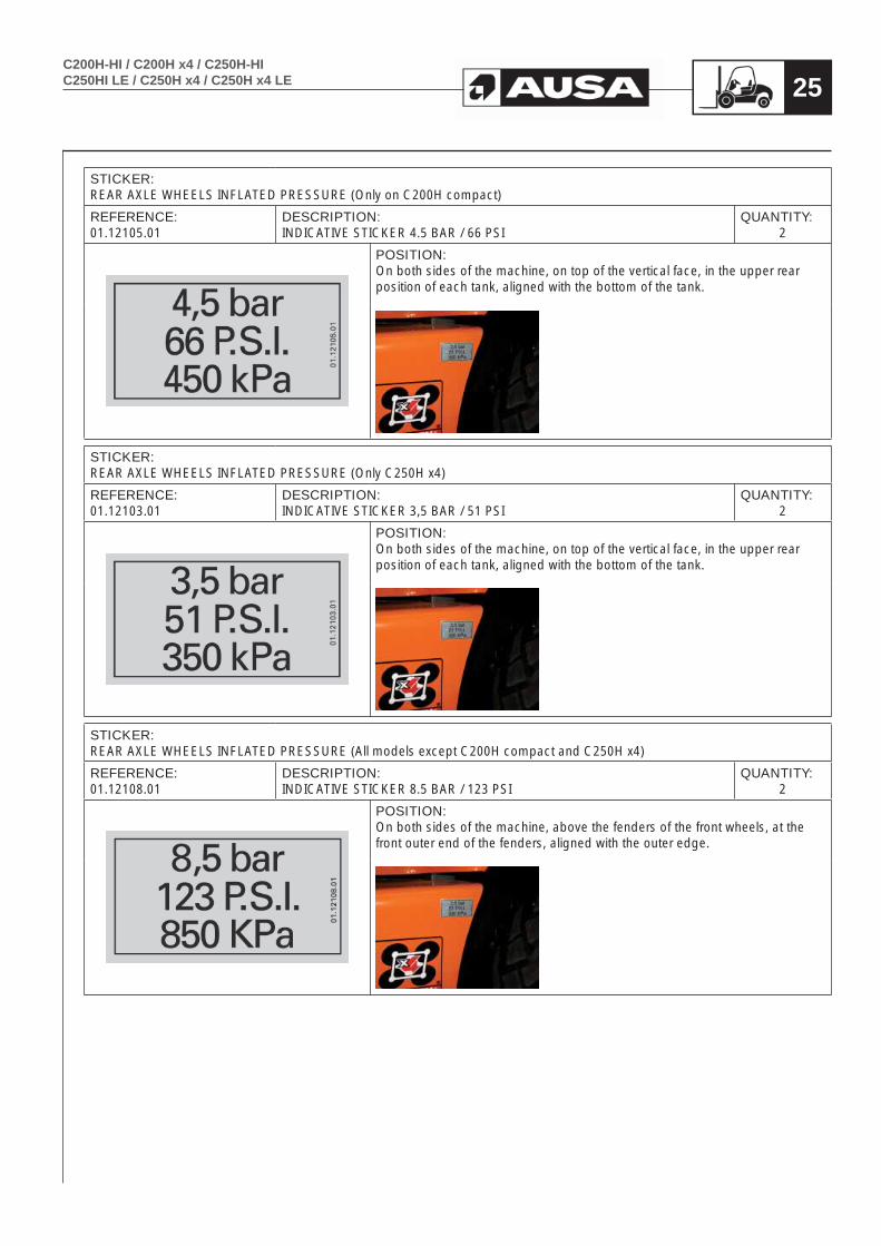
STICKER:REAR AXLE WHEELS INFLATED PRESSURE (Only on C200H compact)
REFERENCE:01.12105.01
DESCRIPTION:INDICATIVE STICKER 4.5 BAR / 66 PSI
QUANTITY:2
POSITION:On both sides of the machine, on top of the vertical face, in the upper rear position of each tank, aligned with the bottom of the tank.
STICKER:REAR AXLE WHEELS INFLATED PRESSURE (Only C250H x4)
REFERENCE:01.12103.01
DESCRIPTION:INDICATIVE STICKER 3,5 BAR / 51 PSI
QUANTITY:2
POSITION:On both sides of the machine, on top of the vertical face, in the upper rear position of each tank, aligned with the bottom of the tank.
STICKER:REAR AXLE WHEELS INFLATED PRESSURE (All models except C200H compact and C250H x4)
REFERENCE:01.12108.01
DESCRIPTION:INDICATIVE STICKER 8.5 BAR / 123 PSI
QUANTITY:2
POSITION:On both sides of the machine, above the fenders of the front wheels, at the front outer end of the fenders, aligned with the outer edge.

26C200H-HI / C200H x4 / C250H-HI
C250HI LE / C250H x4 / C250H x4 LE
STICKER:
FUEL TYPE INDICATION
REFERENCE: DESCRIPTION: QUANTITY:
43.01356.00 INDICATIVE STICKER 90x45 FUEL 1
POSITION:
On the right tank of the machine, next to the fuel cap, aligned with the vertical outer wall of the tank.
STICKER:
EC INDICATION
REFERENCE: DESCRIPTION: QUANTITY:
45.19101.00 INDICATIVE STICKER 70x70 1
POSITION:
On the left side of the machine, at the bottom inner side of the front fenders, aligned on its upper side with mark id 58.01353.01 “To hoist machine”.
STICKER:
HYDRAULIC OIL TYPE
REFERENCE: DESCRIPTION: QUANTITY:
43.01352.20 INDICATIVE STICKER 70x32 HYDRAULIC OIL 1
POSITION:
On the left-hand side tank, below the filler cap, aligned with the inner edge of the tank, and centered with the cap.

27C200H-HI / C200H x4 / C250H-HIC250HI LE / C250H x4 / C250H x4 LE
STICKER:
ENGINE OIL TYPE
REFERENCE: DESCRIPTION: QUANTITY:
43.01170.02 INDICATIVE STICKER 90x45 1
POSITION:
On the inner cab lock, easily legible with the cab raised.
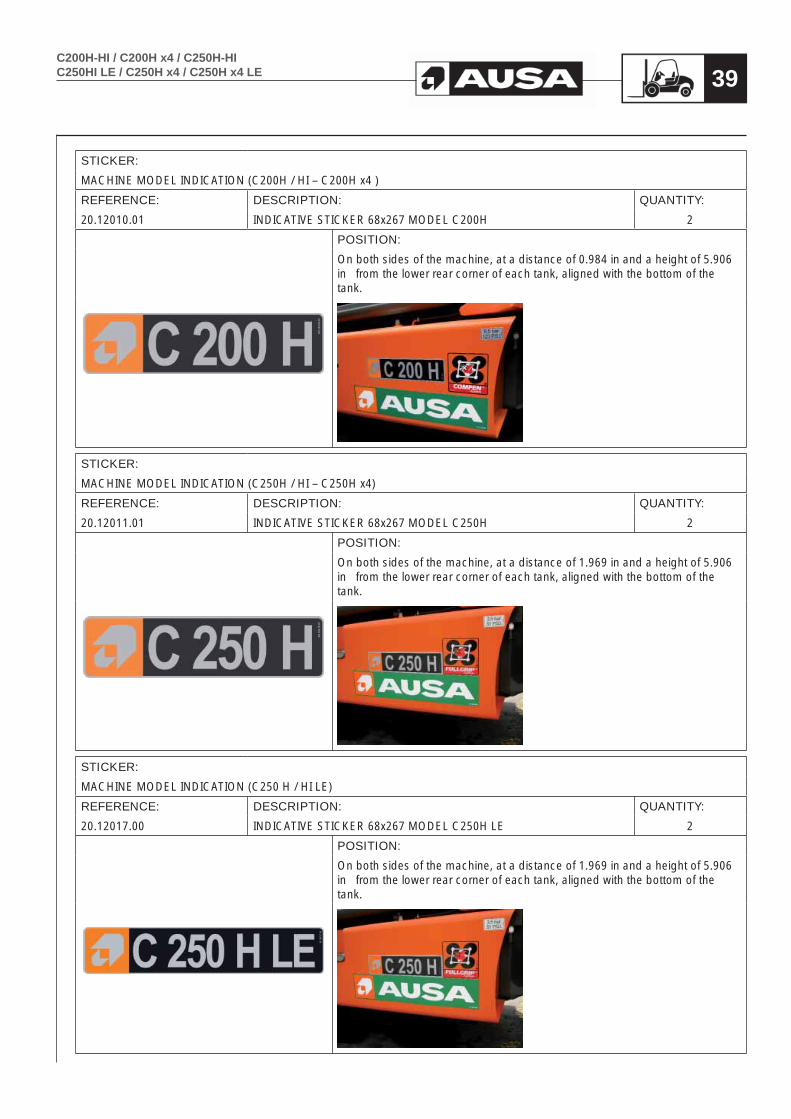
STICKER:
MACHINE MODEL INDICATION (C200H / HI – C200H x4 )
REFERENCE: DESCRIPTION: QUANTITY:
20.12010.01 INDICATIVE STICKER 68x267 MODEL C200H 2
POSITION:
On both sides of the machine, at a distance of 0.984 in and a height of 5.906 in from the lower rear corner of each tank, aligned with the bottom of the tank.
STICKER:
MACHINE MODEL INDICATION (C250H / HI – C250H x4)
REFERENCE: DESCRIPTION: QUANTITY:
20.12011.01 INDICATIVE STICKER 68x267 MODEL C250H 2
POSITION:
On both sides of the machine, at a distance of 1.969 in and a height of 5.906 in from the lower rear corner of each tank, aligned with the bottom of the tank.
28C200H-HI / C200H x4 / C250H-HI
C250HI LE / C250H x4 / C250H x4 LE
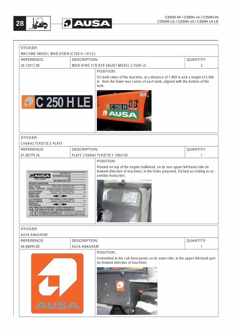
STICKER:
MACHINE MODEL INDICATION (C250 H / HI LE)
REFERENCE: DESCRIPTION: QUANTITY:
20.12017.00 INDICATIVE STICKER 68x267 MODEL C250H LE 2
POSITION:
On both sides of the machine, at a distance of 1.969 in and a height of 5.906 in from the lower rear corner of each tank, aligned with the bottom of the tank.
STICKER:
CHARACTERISTICS PLATE
REFERENCE: DESCRIPTION: QUANTITY:
01.00779.26 PLATE CHARACTERISTICS 100x130 1
POSITION:
Riveted on top of the engine bulkhead, on its rear upper left-hand side (in forward direction of machine), in the holes prepared. Etched according to as-sembly instruction.
STICKER:
AUSA ANAGRAM
REFERENCE: DESCRIPTION: QUANTITY:
46.08099.00 AUSA ANAGRAM 1
POSITION:
Embedded in the cab front panel, on its outer side, in the upper left-hand part (in forward direction of machine).

29C200H-HI / C200H x4 / C250H-HIC250HI LE / C250H x4 / C250H x4 LE
STICKER:
WARNING IN CASE OF OVERTURNING THE MACHINE
REFERENCE: DESCRIPTION: QUANTITY:
12.12010.00 SAFETY STICKER 1
POSITION:
Top left-hand corner of the dashboard, under sticker ref. 02.00774.00 “Do not use” and aligned with this on its left side.
STICKER:
ACOUSTIC OPERATOR PROTECTION
REFERENCE: DESCRIPTION: QUANTITY:
01.00757.00 INDICATIVE STICKER D40 1
POSITION:
Top left-hand corner of the instrument panel, under sticker 02.00774.00 “Do not use”, aligned with this on its right side and centered with sticker ref. 12.12010.00.
STICKER:
POINT HOISTED MACHINE
REFERENCE: DESCRIPTION: QUANTITY:
09.15720.00 INDICATIVE STICKER 35x35 4
POSITION:
Above each of the four eyebolts at the bottom of the frame for lifting the ma-chine.

30C200H-HI / C200H x4 / C250H-HI
C250HI LE / C250H x4 / C250H x4 LE
STICKER:
MAXIMUM SOUND LEVEL (C250H / HI – C250H x4)
REFERENCE: DESCRIPTION: QUANTITY:
09.12014.00 STICKER NOISE 104 DB 1
POSITION:
On the inside of the right front wheel arch, aligned with the cab floor.
STICKER:
MAXIMUM SOUND LEVEL ((C200H / HI – C200H x4 / C250HI LE / C250Hi LE x4)
REFERENCE: DESCRIPTION: QUANTITY:
09.12013.00 STICKER NOISE 103 DB 1
POSITION:
On the inside of the right front wheel arch, aligned with the cab floor.
STICKER:
COMPEN SYSTEM® (C200H x4 / C250H x4 / C250H x4 LE)
REFERENCE: DESCRIPTION: QUANTITY:
43.00395.00 INDICATIVE STICKER 110X110 2
POSITION:
On both sides of the machine, next to the AUSA sticker (ref. 13.12136.00) and aligned on the right side.
31C200H-HI / C200H x4 / C250H-HIC250HI LE / C250H x4 / C250H x4 LE
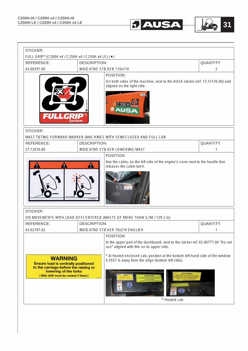
STICKER:
FULL GRIP® (C200H x4 / C250H x4 / C250H x4 LE) ()
REFERENCE: DESCRIPTION: QUANTITY:
43.00397.00 INDICATIVE STICKER 110x110 2
POSITION:
On both sides of the machine, next to the AUSA sticker (ref. 13.12136.00) and aligned on the right side.
STICKER:
MAST TILTING FORWARD MARKER (MACHINES WITH SEMI-CLOSED AND FULL CAB
REFERENCE: DESCRIPTION: QUANTITY:
57.12010.00 INDICATIVE STICKER LOWERING MAST 1
POSITION:
Into the cabin, on the left side of the engine’s cover next to the handle that releases the cabin latch.
STICKER:
ON MOVEMENTS WITH LOAD OFFCENTERED (MASTS OF MORE THAN 3,7M / 12ft 2 in)
REFERENCE: DESCRIPTION: QUANTITY:
43.02187.02 INDICATIVE STICKER 70x210 ENGLISH 1
POSITION:
In the upper part of the dashboard, next to the sticker ref. 02.00777.00 “Do not use” aligned with this on its upper side.
* In heated enclosed cab, position at the bottom left-hand side of the window 0.3937 in away from the edge (bottom left side).
* Heated cab

32C200H-HI / C200H x4 / C250H-HI
C250HI LE / C250H x4 / C250H x4 LE
STICKER:
AUSA STICKER
REFERENCE: DESCRIPTION: QUANTITY:
13.12136.00 AUSA STICKER 2
POSITION:
On both sides of the mast, above the beam, with its lower side aligned at 4ft 95 in from the ground, above the sticker ref. 45.01352.00 “Dangerous area”, and 0.3937 in away from it.
STICKER:
INDICATION TRANSFER BOX OIL. (C200H x4 / C250H x4 / C250H x4 LE)
REFERENCE: DESCRIPTION: QUANTITY:
43.00396.02 INDICATIVE STICKER 60x95 1
POSITION:
Into the engine compartment on the external face of the joystick control valve support, above “Brake fluid indication” sticker.
STICKER:
NOT USE WITHOUT AUTHORIZATION
REFERENCE: DESCRIPTION: QUANTITY:
02.00777.00 INDICATIVE STICKER 50x120 ENGLISH 1
POSITION:
Top left-hand corner of the dashboard, aligned on its left side with sticker nº 12.12010.00 “Safety warning”.

33C200H-HI / C200H x4 / C250H-HIC250HI LE / C250H x4 / C250H x4 LE
STICKER:
BRAKE FLUID INDICATION
REFERENCE: DESCRIPTION: QUANTITY:
43.70780.01 INDICATIVE STICKER 60x100 BRAKE 1
POSITION:
Into the engine compartment on the external face of the joystick control valve support, below “Transfer box oil” sticker.
STICKER:
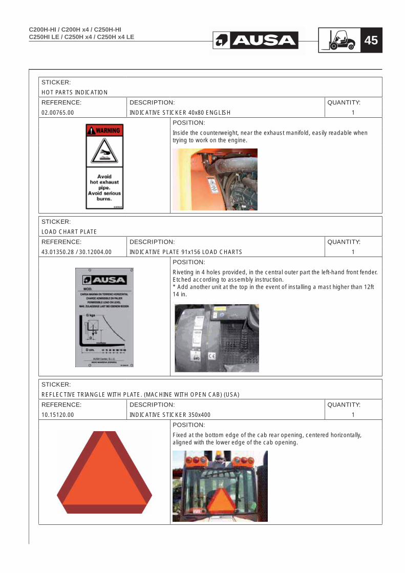
HOT PARTS INDICATION
REFERENCE: DESCRIPTION: QUANTITY:
02.00765.00 INDICATIVE STICKER 40x80 ENGLISH 1
POSITION:
Inside the counterweight, near the exhaust manifold, easily readable when trying to work on the engine.
STICKER:
LOAD CHART PLATE
REFERENCE: DESCRIPTION: QUANTITY:
43.01350.28 / 30.12004.00 INDICATIVE PLATE 91x156 LOAD CHARTS 1
POSITION:
Riveting in 4 holes provided, in the central outer part the left-hand front fender. Etched according to assembly instruction. * Add another unit at the top in the event of installing a mast higher than 12ft 14 in.
34C200H-HI / C200H x4 / C250H-HI
C250HI LE / C250H x4 / C250H x4 LE
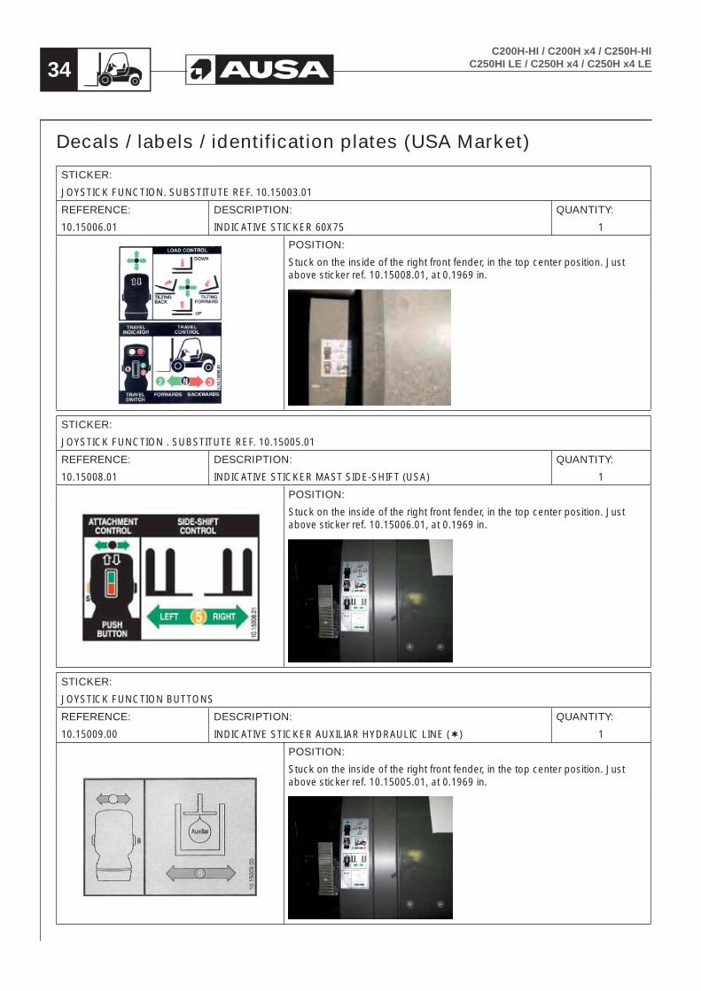
Decals / labels / identification plates (USA Market)
STICKER:
JOYSTICK FUNCTION. SUBSTITUTE REF. 10.15003.01
REFERENCE: DESCRIPTION: QUANTITY:
10.15006.01 INDICATIVE STICKER 60X75 1
POSITION:
Stuck on the inside of the right front fender, in the top center position. Just above sticker ref. 10.15008.01, at 0.1969 in.
STICKER:
JOYSTICK FUNCTION . SUBSTITUTE REF. 10.15005.01
REFERENCE: DESCRIPTION: QUANTITY:
10.15008.01 INDICATIVE STICKER MAST SIDE-SHIFT (USA) 1
POSITION:
Stuck on the inside of the right front fender, in the top center position. Just above sticker ref. 10.15006.01, at 0.1969 in.
STICKER:
JOYSTICK FUNCTION BUTTONS
REFERENCE: DESCRIPTION: QUANTITY:
10.15009.00 INDICATIVE STICKER AUXILIAR HYDRAULIC LINE () 1
POSITION:
Stuck on the inside of the right front fender, in the top center position. Just above sticker ref. 10.15005.01, at 0.1969 in.

35C200H-HI / C200H x4 / C250H-HIC250HI LE / C250H x4 / C250H x4 LE
STICKER:
JOYSTICK FUNCTION BUTTONS
REFERENCE: DESCRIPTION: QUANTITY:
10.15011.00 INDICATIVE STICKER 4WD CONNECTION () 1
POSITION:
Stuck on the inside of the right front fender, in the top center position. Just above sticker ref. 10.15005.01 o 10.15009.00, at 0.1969 in.
STICKER:
DANGEROUS AREA.. SUBSTITUTE REF. 45.01352.00
REFERENCE: DESCRIPTION: QUANTITY:
45.01352.01 INDICATIVE STICKER 2
POSITION:
On both sides of the mast, above the beam, with its upper side aligned at 4ft 92 in from the ground, below the sticker ref. 13.12136.00 “AUSA Make”, and 0.3937 in away from it.
STICKER:
TO HOIST MACHINE
REFERENCE: DESCRIPTION: QUANTITY:
58.01353.01 INDICATIVE STICKER 105X100 2
POSITION:
On both sides of the machine, at the lower exterior part of the front fenders.

36C200H-HI / C200H x4 / C250H-HI
C250HI LE / C250H x4 / C250H x4 LE
STICKER:
AUSA
REFERENCE: DESCRIPTION: QUANTITY:
13.12136.00 AUSA STICKER 2
POSITION:
On both sides of the machine, at a distance of 0.984 in and a height of 1.969 in from the lower rear corner of each tank, aligned with the bottom of the tank.
STICKER:
FRONT AXLE WHEELS INFLATED PRESSURE (Only on C200H compact)
REFERENCE: DESCRIPTION: QUANTITY:
01.12107.00 INDICATIVE STICKER 6,5 BAR / 96 PSI 2
POSITION:
On both sides of the machine, above the fenders of the front wheels, at the front outer end of the fenders, aligned with the outer edge.
STICKER:
FRONT AXLE WHEELS INFLATED PRESSURE (ALL MODELS EXCEPT C200H compact)
REFERENCE: DESCRIPTION: QUANTITY:
01.12105.01 INDICATIVE STICKER 4,5 BAR / 66 PSI 2
POSITION:
On both sides of the machine, above the fenders of the front wheels, at the front outer end of the fenders, aligned with the outer edge.

37C200H-HI / C200H x4 / C250H-HIC250HI LE / C250H x4 / C250H x4 LE
STICKER:
REAR AXLE WHEELS INFLATED PRESSURE (Only on C200H compact)
REFERENCE: DESCRIPTION: QUANTITY:
01.12105.01 INDICATIVE STICKER 4.5 BAR / 66 PSI 2
POSITION:
On both sides of the machine, on top of the vertical face, in the upper rear position of each tank, aligned with the bottom of the tank.
STICKER:
REAR AXLE WHEELS INFLATED PRESSURE (Only C250H x4)
REFERENCE: DESCRIPTION: QUANTITY:
01.12103.01 INDICATIVE STICKER 3,5 BAR / 51 PSI 2
POSITION:
On both sides of the machine, on top of the vertical face, in the upper rear position of each tank, aligned with the bottom of the tank.
STICKER:
REAR AXLE WHEELS INFLATED PRESSURE (All models except C200H compact and C250H x4)
REFERENCE: DESCRIPTION: QUANTITY:
01.12108.01 INDICATIVE STICKER 8.5 BAR / 123 PSI 2
POSITION:
On both sides of the machine, above the fenders of the front wheels, at the front outer end of the fenders, aligned with the outer edge.

38C200H-HI / C200H x4 / C250H-HI
C250HI LE / C250H x4 / C250H x4 LE
STICKER:
FUEL TYPE INDICATION
REFERENCE: DESCRIPTION: QUANTITY:
43.01356.00 INDICATIVE STICKER 90x45 FUEL 1
POSITION:
On the right tank of the machine, next to the fuel cap, aligned with the vertical outer wall of the tank.
STICKER:
HYDRAULIC OIL TYPE (USA). SUBSTITUTE REF. 43.01352.20
REFERENCE: DESCRIPTION: QUANTITY:
60.01352.01 INDICATIVE STICKER 70x32 HYDRAULIC OIL 1
POSITION:
On the left-hand side tank, below the filler cap, aligned with the inner edge of the tank, and centered with the cap.
STICKER:
ENGINE OIL TYPE. SUBSTITUTE REF. 43.01170.02
REFERENCE: DESCRIPTION: QUANTITY:
43.01170.03 INDICATIVE STICKER 90x45 1
POSITION:
On the inner cab lock, easily legible with the cab raised.
39C200H-HI / C200H x4 / C250H-HIC250HI LE / C250H x4 / C250H x4 LE
STICKER:
MACHINE MODEL INDICATION (C200H / HI – C200H x4 )
REFERENCE: DESCRIPTION: QUANTITY:
20.12010.01 INDICATIVE STICKER 68x267 MODEL C200H 2
POSITION:
On both sides of the machine, at a distance of 0.984 in and a height of 5.906 in from the lower rear corner of each tank, aligned with the bottom of the tank.
STICKER:
MACHINE MODEL INDICATION (C250H / HI – C250H x4)
REFERENCE: DESCRIPTION: QUANTITY:
20.12011.01 INDICATIVE STICKER 68x267 MODEL C250H 2
POSITION:
On both sides of the machine, at a distance of 1.969 in and a height of 5.906 in from the lower rear corner of each tank, aligned with the bottom of the tank.
STICKER:
MACHINE MODEL INDICATION (C250 H / HI LE)
REFERENCE: DESCRIPTION: QUANTITY:
20.12017.00 INDICATIVE STICKER 68x267 MODEL C250H LE 2
POSITION:
On both sides of the machine, at a distance of 1.969 in and a height of 5.906 in from the lower rear corner of each tank, aligned with the bottom of the tank.

40C200H-HI / C200H x4 / C250H-HI
C250HI LE / C250H x4 / C250H x4 LE
STICKER:
CHARACTERISTICS PLATE. SUBSTITUTE 01.00779.26
REFERENCE: DESCRIPTION: QUANTITY:
01.00779.23 PLATE CHARACTERISTICS 100x130 SPECIAL 1
POSITION:
Riveted on top of the engine bulkhead, on its rear upper left-hand side (in forward direction of machine), in the holes prepared. Etched according to as-sembly instruction.
STICKER:
AUSA ANAGRAM
REFERENCE: DESCRIPTION: QUANTITY:
46.08099.00 AUSA ANAGRAM 1
POSITION:
Embedded in the cab front panel, on its outer side, in the upper left-hand part (in forward direction of machine).
STICKER:
WARNING IN CASE OF OVERTURNING THE MACHINE
REFERENCE: DESCRIPTION: QUANTITY:
12.12010.00 SAFETY STICKER 1
POSITION:
Top left-hand corner of the dashboard, under sticker ref. 02.00774.00 “Do not use” and aligned with this on its left side.

41C200H-HI / C200H x4 / C250H-HIC250HI LE / C250H x4 / C250H x4 LE
STICKER:
ACOUSTIC OPERATOR PROTECTION
REFERENCE: DESCRIPTION: QUANTITY:
01.00757.00 INDICATIVE STICKER D40 1
POSITION:
Top left-hand corner of the instrument panel, under sticker 02.00774.00 “Do not use”, aligned with this on its right side and centered with sticker ref. 12.12010.00.
STICKER:
POINT HOISTED MACHINE
REFERENCE: DESCRIPTION: QUANTITY:
09.15720.00 INDICATIVE STICKER 35x35 4
POSITION:
Above each of the four eyebolts at the bottom of the frame for lifting the ma-chine.
STICKER:
MAXIMUM SOUND LEVEL (C250H / HI – C250H x4)
REFERENCE: DESCRIPTION: QUANTITY:
09.12014.00 STICKER NOISE 104 DB 1
POSITION:
On the inside of the right front wheel arch, aligned with the cab floor.

42C200H-HI / C200H x4 / C250H-HI
C250HI LE / C250H x4 / C250H x4 LE
STICKER:
MAXIMUM SOUND LEVEL (C200H / HI – C200H x4 / C250HI LE / C250Hi LE x4)
REFERENCE: DESCRIPTION: QUANTITY:
09.12013.00 STICKER NOISE 103 DB 1
POSITION:
On the inside of the right front wheel arch, aligned with the cab floor.
STICKER:
COMPEN SYSTEM® (C200H x4 / C250H x4 / C250H x4 LE)
REFERENCE: DESCRIPTION: QUANTITY:
43.00395.00 INDICATIVE STICKER 110X110 2
POSITION:
On both sides of the machine, next to the AUSA sticker (ref. 13.12136.00) and aligned on the right side.
STICKER:
FULL GRIP® (C200H x4 / C250H x4 / C250H x4 LE) ()
REFERENCE: DESCRIPTION: QUANTITY:
43.00397.00 INDICATIVE STICKER 110x110 2
POSITION:
On both sides of the machine, next to the AUSA sticker (ref. 13.12136.00) and aligned on the right side.

43C200H-HI / C200H x4 / C250H-HIC250HI LE / C250H x4 / C250H x4 LE
STICKER:
MAST TILTING FORWARD MARKER (MACHINES WITH SEMI-CLOSED AND FULL CAB
REFERENCE: DESCRIPTION: QUANTITY:
57.12010.00 INDICATIVE STICKER LOWERING MAST 1
POSITION:
Into the cabin, on the left side of the engine’s cover next to the handle that releases the cabin latch.
STICKER:
NON MOVEMENTS WITH LOAD OFFCENTERED (MASTS OF MORE THAN 3,7M / 12ft 2 in). SUBSTITUTE REF. 43.02187.02
REFERENCE: DESCRIPTION: QUANTITY:
43.02187.02 INDICATIVE STICKER 70x210 ENGLISH 1
POSITION:
In the upper part of the dashboard, next to the sticker ref. 10.01414.01 “Indica-tion structure” aligned with this on its upper side.
* In heated enclosed cab, position at the bottom left-hand side of the window 0.3937 in away from the edge (bottom left side).
* Heated cab
STICKER:
AUSA STICKER
REFERENCE: DESCRIPTION: QUANTITY:
13.12136.00 AUSA STICKER 2
POSITION:
On both sides of the mast, above the beam, with its lower side aligned at 4ft 95 in from the ground, above the sticker ref. 45.01352.00 “Dangerous area”, and 0.3937 in away from it.

44C200H-HI / C200H x4 / C250H-HI
C250HI LE / C250H x4 / C250H x4 LE
STICKER:
INDICATION TRANSFER BOX OIL. (C200H x4 / C250H x4 / C250H x4 LE)
REFERENCE: DESCRIPTION: QUANTITY:
43.00396.02 INDICATIVE STICKER 60x95 1
POSITION:
Into the engine compartment on the external face of the joystick control valve support, above “Brake fluid indication” sticker.
STICKER:
OT USE WITHOUT AUTHORIZATION. SUBSTITUTE REF. 02.00777.00
REFERENCE: DESCRIPTION: QUANTITY:
02.00777.04 INDICATIVE STICKER 216x250 ENGLISH 1
POSITION:
On top of the vertical face of the engine cover, easily readable before access-ing the forklift, aligned with the cab floor.
STICKER:
BRAKE FLUID INDICATION
REFERENCE: DESCRIPTION: QUANTITY:
43.70780.01 INDICATIVE STICKER 60x100 BRAKE 1
POSITION:
Into the engine compartment on the external face of the joystick control valve support, below “Transfer box oil” sticker.
45C200H-HI / C200H x4 / C250H-HIC250HI LE / C250H x4 / C250H x4 LE
STICKER:
HOT PARTS INDICATION
REFERENCE: DESCRIPTION: QUANTITY:
02.00765.00 INDICATIVE STICKER 40x80 ENGLISH 1
POSITION:
Inside the counterweight, near the exhaust manifold, easily readable when trying to work on the engine.
STICKER:
LOAD CHART PLATE
REFERENCE: DESCRIPTION: QUANTITY:
43.01350.28 / 30.12004.00 INDICATIVE PLATE 91x156 LOAD CHARTS 1
POSITION:
Riveting in 4 holes provided, in the central outer part the left-hand front fender. Etched according to assembly instruction. * Add another unit at the top in the event of installing a mast higher than 12ft 14 in.
STICKER:
REFLECTIVE TRIANGLE WITH PLATE. (MACHINE WITH OPEN CAB) (USA)
REFERENCE: DESCRIPTION: QUANTITY:
10.15120.00 INDICATIVE STICKER 350x400 1
POSITION:
Fixed at the bottom edge of the cab rear opening, centered horizontally, aligned with the lower edge of the cab opening.

46C200H-HI / C200H x4 / C250H-HI
C250HI LE / C250H x4 / C250H x4 LE
STICKER:
REFLECTIVE TRIANGLE (MACHINES WITH SEMI-CLOSED AND FULL CAB)) (USA)
REFERENCE: DESCRIPTION: QUANTITY:
10.15122.00 INDICATIVE STICKER 356x356 1
POSITION:
On the cab rear window, centered horizontally on the glass, aligned with the lower edge 0.3937 in away from it.
STICKER:
NOT TO TOUCH INDICATION
REFERENCE: DESCRIPTION: QUANTITY:
02.00766.00 INDICATIVE STICKER 40x80 USA 1
POSITION:
On the top of the radiator fan guard.
STICKER:
PROTECTION STRUCTURE INDICATION
REFERENCE: DESCRIPTION: QUANTITY:
10.01414.01 INDICATIVE STICKER 60x125 USA 1
POSITION:
In the upper left-hand corner of the dashboard, aligned at the left with the adhesive ref. 10.01414.01 “Warning Security”.

47C200H-HI / C200H x4 / C250H-HIC250HI LE / C250H x4 / C250H x4 LE
STICKER:
CALIFORNIA INDICATION (USA)
REFERENCE: DESCRIPTION: QUANTITY:
43.01171.00 INDICATIVE STICKER 42x77 1
POSITION:
In the upper right-hand corner of the dashboard, aligned at the top with the bend in the dashboard.
C200H-HI / C200H x4 / C250H-HIC250HI LE / C250H x4 / C250H x4 LE48
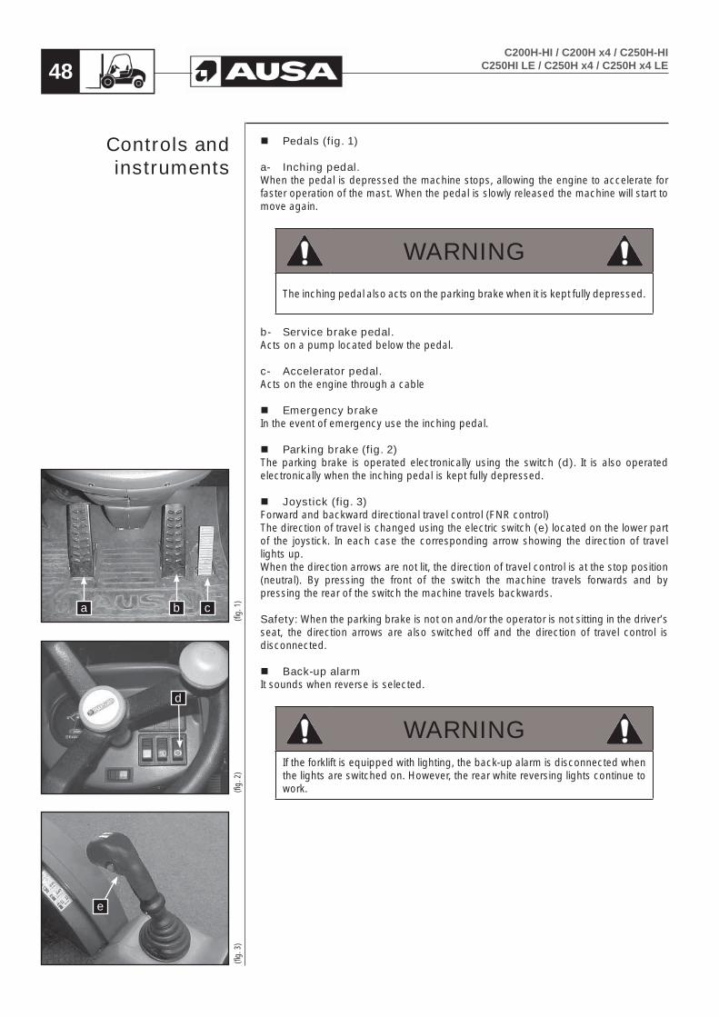
Pedals (fig. 1)
a- Inching pedal. When the pedal is depressed the machine stops, allowing the engine to accelerate for faster operation of the mast. When the pedal is slowly released the machine will start to move again.
WARNING
The inching pedal also acts on the parking brake when it is kept fully depressed.
b- Service brake pedal. Acts on a pump located below the pedal.
c- Accelerator pedal. Acts on the engine through a cable
Emergency brakeIn the event of emergency use the inching pedal.
Parking brake (fig. 2)The parking brake is operated electronically using the switch (d). It is also operated electronically when the inching pedal is kept fully depressed.
Joystick (fig. 3)Forward and backward directional travel control (FNR control)The direction of travel is changed using the electric switch (e) located on the lower part of the joystick. In each case the corresponding arrow showing the direction of travel lights up.When the direction arrows are not lit, the direction of travel control is at the stop position (neutral). By pressing the front of the switch the machine travels forwards and by pressing the rear of the switch the machine travels backwards.
Safety: When the parking brake is not on and/or the operator is not sitting in the driver’s seat, the direction arrows are also switched off and the direction of travel control is disconnected.
Back-up alarmIt sounds when reverse is selected.
WARNINGIf the forklift is equipped with lighting, the back-up alarm is disconnected when the lights are switched on. However, the rear white reversing lights continue to work.
Controls and instruments
(fig.
2)
d
(fig.
3)
e
(fig.
1)
a b c

C200H-HI / C200H x4 / C250H-HIC250HI LE / C250H x4 / C250H x4 LE 49
Horn (fig. 1, 2)
Standard machine: The horn is operated using the button (f) located on the right of the joystick.
Machine equipped with Full Grip ® System (): The horn is operated using the button (g) located on the upper right switch of the instrument panel.
Speed control (fig. 3) Only in C200H-HI / C200H x4 / C250HI LE / C250H x4 LEPushing the joystick switch button (h) the fast speed is connected/disconnected. When it is connected the fast speed lamp on the instrument panel is lit.
4x4 connection (Full Grip® System) () (fig. 4)
Connecting the 4x4The 4x4 connects by pressing yellow switch (i) located underneath the joystick at the right side.
Disconnecting the 4x4The 4x4 disconnects just leaving yellow switch (i) on its rest position.
CAUTION
Do not connect the 4x4 traction at high speed
REMARK: Moreover, some models may differ from (fig. 4) and assemble a plastic plug instead of red switch (h).
(Abb
. 4)
(Abb
. 3)
(Abb
. 2)
(Abb
. 1)
Controls and instruments
(fig.
2)
(fig.
3)
(fig.
4)
(fig.
1)
f
6
h
5
i h
f

C200H-HI / C200H x4 / C250H-HIC250HI LE / C250H x4 / C250H x4 LE50
Load handling controls (fig. 1)The mast and the load are moved by using the joystick.
Raising and lowering the mast.If the joystick is pulled backwards the mast and the forks lift and if pushed forwards the mast and the forks lower.
Tilting the forks.If the joystick is pulled to the left, the mast forks tilt backwards (forks lift) and if pushed to the right, they tilt forward (forks lower).
Side-shift (fig. 2).By holding down button (5) on the joystick and pulling the joystick to the left, the forks move to the left.By holding down button (5) and pushing the joystick to the right the forks move to the right.Always centre the carriage when in transit or when transporting a load.
Additional hydraulic control for attachments () (fig. 3).By holding down button (6) of the joystick and pulling it to the left (towards the operator), or pushing it to the right, pressure is supplied to the quick hydraulic
WARNINGThe fork positioner allows the operator to set the forks with a variable gap matching different pallet size without removing the forks manually.Be aware this attachment is NOT foreseen for lateral pushing operation (similar to an hydraulic clamp).This type of operation is forbidden, it could be dangerous for the persons and it is considered a misuse, consequently, the manufacturer does not accept any claim for damages caused in this way.
(fig.
3)
(fig.
2)
(fig.
1)
Controls and instruments

C200H-HI / C200H x4 / C250H-HIC250HI LE / C250H x4 / C250H x4 LE 51
Starter switch (fig. 1)See section “Starting the engine”
a- In this position the ignition and the engine are disconnected.b- Ignition on. The engine pre-heating system and the lamp on the control panel are
activated for a few seconds.c- Starter. Turning the key to position (c) starts the engine.
Before re-starting the engine, the key should first be switched to position (a).
Fuse box (fig. 2)This is located at the right of the steering column, next to the starter switch.See the section “Electric circuit” in this Operator’s and Safety Manual to identify the number and function of each fuse.
Instrument Panel and controls
(fig.
2)
(fig.
1)
a
b c

C200H-HI / C200H x4 / C250H-HIC250HI LE / C250H x4 / C250H x4 LE52
NOTEFor ease of understanding, the picture shows the panel with the steering wheel removed.
Standard Instrument panel: Components and Operation (fig. 1)
1- Multi-function instrument. See the section “Multi-function instrument”.2- Light switch. This switch has two positions, the first switches on the low beam
and the second switches on the high beam.3- Heating switch (). This has two positions to give two fan speeds.4- Working light switch (). To connect the front lights switch turn on the switch.5- Parking brake. To activate the forklift parking brake, press the switch.6- Windscreen wiper switch (). To switch on the windscreen wiper, press the
switch. To activate the windscreen wiper washer pump, press the same switch again.
7- Rotating beacon switch. To switch on, press the button and it will light up. To switch off, press the button again.
8- Indicators switch (). The turning indicators are switched on by pressing the switch to the left or to the right.
9- Hazard lights switch (). To switch on, press the button and it will blink. To switch off, press the button again.
Instrument Panel and controls
1 2
789
3
6
4
5

C200H-HI / C200H x4 / C250H-HIC250HI LE / C250H x4 / C250H x4 LE 53
Machine equipped with Full Grip® System Instrument panel (): Components and Operation (fig. 1)
1- Multi-function instrument. See the section “Multi-function instrument”.2- Light switch. This switch has two positions, the first switches on the low beam
and the second switches on the high beam.3- Heating switch (). This has two positions to give two fan speeds.4- Horn switch. To activate the horn, press the switch.5- Parking brake. To activate the forklift parking brake, press the switch.6- Windscreen wiper switch (). To switch on the windscreen wiper, press the
switch. To activate the windscreen wiper washer pump, press the same switch again.
7- Rotating beacon switch. To switch on, press the button and it will light up. To switch off, press the button again.
8- Indicators switch (). The turning indicators are switched on by pressing the switch to the left or to the right.
9- Working light switch (). To connect the front lights switch turn on the switch.10- Hazard lights switch (). To switch on, press the button and it will blink. To
switch off, press the button again.
Instrument Panel and controls
1
10 9 8 7 6 5
2 3 4

C200H-HI / C200H x4 / C250H-HIC250HI LE / C250H x4 / C250H x4 LE54
Multifunction instrument (fig. 1)
A- Hourmeter. This gauge indicates the total running time of the forklift engine to enable servicing of the engine at proper intervals. (See MAINTENANCE CHART for servicing frequency).
B- Fuel level. This gauge indicates the diesel fuel level in the tank.
C- Fuel reserve indicator lamp. This lights up when the level of fuel in the tank falls into reserve.
D- Air filter warning lamp. When the air filter of the diesel engine becomes clogged with dirt, this lamp will light. The air filter should be immediately cleaned or serviced.
E- Engine pre-heat indicator lamp. When this lamp glows it indicates that the engine pre-heat plugs are in operation and heating the combustion chamber the temperature required to start the engine.
F- Hydraulic oil level warning lamp. This lights up and emits an audible warning when the hydraulic oil level is at the minimum level. Oil should be added to top up the level to the correct level
G- Engine oil pressure warning lamp. When the ignition is on, this lamp lit and turns off when the engine is running. If this lamp turns on emits an audible warning while the engine is running, the engine must be stopped immediately to prevent damages. Check the level and add oil if necessary.
(fig. 1)
Instrument Panel and controls

C200H-HI / C200H x4 / C250H-HIC250HI LE / C250H x4 / C250H x4 LE 55
H- Battery charge warning lamp. This lamp shows the condition of the battery and indicates if the battery charge is too low or if the alternator is not charging properly. Once the engine starts to run, this red lamp turns off If it remains lit, stop the engine and determine the cause.
I- Engine temperature warning lamp. This gauge shows the temperature of the coolant in the engine cooling system. When this lamp glows emits an audible warning means that the engine is operating at high temperature which could damage the engine. The engine should be stopped immediately to determine the cause of the high temperature. It could be low coolant, debris in the radiator or a thermostat, which does not operate correctly.
J- Transmission fast speed indicator lamp C200H-HI / C200H x4 / C250HI LE / C250H x4 LE.
This lamp is lit when the fast speed is selected.
K- High beam indicator lamp (with lighting equipment) (). This lamp is lit when high beams are selected.
L- Turn signal indicator lamp (with lighting equipment) (). This lamp will blink indicating turn signals are operating.
Fuel
The current regulations of exhaust emissions, require that, for the whole life of the machine, the level on the different components of these emissions, are under the maximum figures stated on the regulations.As a consequence of that, the maintenance plan of the engine has to be followed up carefully, giving special attention to the quality and pureness of the fuel, the cleanliness of the filters and, in general, to the general maintenance of the fuel circuit.
Handling
- Only use the fuel type authorized by AUSA. Do not use fuel mixed with oil, other fuels or unsuitable additives.
- The correct fuel for the forklift is diesel. For further details regarding fuel type and required specifications see the section “Fluids and lubricants”.
- Do not allow the fuel to come into contact with the skin and avoid inhaling the fumes, which are toxic. High concentrations of fuel vapour may cause sickness, loss of consciousness or even loss of life in the event of prolonged exposure. If you experience symptoms such as sickness or loss of consciousness seek medical advice immediately.
Instrument Panel and controls

C200H-HI / C200H x4 / C250H-HIC250HI LE / C250H x4 / C250H x4 LE56
- Do not store fuel in closed places. The fuel vapours will alter the atmosphere of the enclosure and may cause a fire or explosion.
- Use suitable impermeable clothing, safety glasses and gloves when handling fuel. When refuelling from a tank, bucket or barrel using a siphon, the following precautions should be taken.
- If refuelling is by gravity, from a raised tank, open the fuel output valve of the tank slowly.
- If the tank or barrel does not have an output valve use a suitable vacuum pump.
WARNINGNever suck the fuel into the pipe by mouth to start the siphoning. Fuel and its vapours are highly toxic.
- In the event of fuel spillage, please inform the supervisor, mark the area suitably and cover the spillage with absorbent material.
- Take suitable measures to avoid risk until the remains of the fuel have been completely removed.
Refuelling
WARNINGSmoking, naked flames or sparks are not permitted in the refuelling area. Fuel vapours can be explosive.
- Refuel in a well-ventilated area.
- Position the forklift as close as possible to the fuel pump so that the filler hose reaches the opening of the tank comfortably.
- Apply the parking brake, switch off the engine and lights, including the rotating beacon.
NOTEIf the fuel pump is equipped with a vehicle earth connection, connect this to a non-isolated metal component of the forklift.
- Clean the fuel cap and surrounding area with a cloth if they have been dirtied. Do not allow dust, water, or any other substance to enter the tank.
- Open the fuel cap using the key and turning to the left.
- Fill the tank without exceeding the volume specified for the forklift. Take care not to spill fuel outside the tank. If you do, clean immediately and dry the surface well.
- Close the tank using the key and remove it from the cap. Check that the cap is correctly closed.
Instrument Panel and controls

C200H-HI / C200H x4 / C250H-HIC250HI LE / C250H x4 / C250H x4 LE 57
WARNINGBefore each period of operation, check the forklift for correct operation of the steering, brakes, hydraulic controls, instruments and safety equipment. Check the neutral position of the FNR switch. A machine that runs correctly is more efficient and can prevent accidents. Make all necessary adjustments or repairs before you operate the machine.
Entering and leaving the operator cabin (fig. 1)Don’t hold and pull of the steering wheel to come in/out the forklift, use the handles located on the overhead guard and always place your foot on the rough bands of the step, to prevent any downfall when you come in or come out.
Adjusting the seat and the steering wheel (figs. 2, 3, 4, 5)Before using the forklift adjust the seat and the steering wheel to a comfortable driving position.
On all machines the operator is able to adjust the seat in the fore-aft direction by lifting knob (a) and sliding seat to the desired position, then releasing the knob to lock the seat into position.
The seat suspension may be adjusted from 132 to 264 lb. (60 to120 Kg) for driver’s weight by turning knob (b). Turning clockwise the weight decreases and turning counter-clockwise it increases. Seats normally leave the factory adjusted for a driver weighting 198 lb. (90 Kg).
It is also possible to adjust the seat backrest angle. The seat backrest tilts forward or backwards by turning knob (c).
WARNING
Securely fasten the seat belt.
(fig.
3)
(fig.
4)
(fig.
5)
(fig.
2)
Operatingthe forklift
(fig.
1)
b
bc
a
a
c

C200H-HI / C200H x4 / C250H-HIC250HI LE / C250H x4 / C250H x4 LE58
The position of the steering wheel is adjusted by tilting forward/backwards the steering column. Loose the lever (d) and release the steering column. Adjust it to the most comfortable position. Tight lever (d) to lock it again.
Starting the engine (fig. 2)
WARNINGFor safety reasons, when starting the engine the driver should be seated, directional control switch in neutral, seatbelt fastened and the parking brake applied.
Starting engine when the operator is seated:The engine starts when accomplishing one of these two conditions o both at the same time:
- FNR control switch in neutral - Parking brake switch on.
Starting engine when the operator is not seated:The FNR control switch o the parking brake switch can be in any position.
Then proceed as follows:
- Place the key in the ignition switch and turn to position (b) ignition. Wait a few moments until the engine preheating light goes out.
- Press the accelerator pedal 1/4 of the way and turn the key to position (c) to start the engine. Do not hold the key in this position for more than 15 seconds. If the engine does not start, repeat the above steps and wait 30 seconds between each attempt. Before re starting the engine, the key should first be switched to position (a).
CAUTIONWith ambient temperatures lower than 0ºC (32ºF), AUSA recommends to run the engine at idle speed for 3 minutes before starting to work with the forklift in order to reach the appropriate fluency on the engine and hydraulic oil
Checks
With the engine running at idle and the forklift is warming-up, carry out the following tests:
- Check the instrument panel controls.- Check the steering by turning it gently to the left and right.- Lift the forks off the ground 6 in (15 cm).- Check the parking brake.- Check that the brake pedal action is firm.
Operatingthe forklift
(fig.
1)
d
(fig.
2)
ab c

C200H-HI / C200H x4 / C250H-HIC250HI LE / C250H x4 / C250H x4 LE 59
Forklift nominal loadThe Rated Capacity of this forklift is the weight the machine is capable of lifting under safe operating conditions. The lifting capacity of a forklift is determined by the height and weight limits of the load. Poor ground conditions as well as shape of the load may reduce the weight that can be safely lifted. Overloading the forks can make the forklift unstable, hard to handle, and may be in danger of tipping over.Inspect the load you intend to lift and make certain it is within the limits of the Load Capacity Chart located on the left hand side mudguard.
Load Center (fig. 1, 2)To rate the lifting capacity of forklifts manufacturers have standardized on a certain size of load. The rated capacity of this forklift is based on a cube measuring 48in (1 m.), in all three dimensions with the center of gravity in the center of this cube. This is known as 24in (600 mm) o 20in (500 mm.)load center from both the vertical face of the mast and from the lifting surface of the forks. lt is important to keep load center in mind for as the load center increases the lifting capacity of the forklift decreases.
Load Capacity
With the load center of the load at 20 in (500 mm.) from vertical face of the forks, the C 200 H-HI and C 200 H x4 has a rated capacity of 2000 Kg.
With the load center of the load at 24 in (600 mm.) from vertical face of the forks, the C 200 H-HI and C 200 H x4 has a rated capacity of 4040 lbs (2000 Kg).
With the load center of the load at 20 in (500 mm.) from vertical face of the forks, the C 250 H-HI / C 250 H x4 / C 250 H x4 LE / C 250 HI x4 LE has a rated capacity of 2500 Kg.
With the load center of the load at 24 in (600 mm.) from vertical face of the forks, the C 250 H-HI / C 250 H x4 / C 250 H x4 LE / C 250 HI x4 has a rated capacity of 5060 lbs (2294 Kg).
If the load is too heavy split it and re-stack it. Use of attachments other than the pallet forks that came with this machine may reduce lifting capacity and affect other machine handling characteristics.
Reproduced copies of the Load Charts are included in the section “Tecnical Specifications” on this Operator’s and Safety Manual. Study the Load Capacity Chart of your machine carefully and make certain you understand it before lifting loads on the forks
(fig.
2)
(fig.
1) 6
00 m
m(fi
g. 1
) 600
mm
(fig.
1) 5
00 m
m
Operatingthe forklift
1- Fork Face2- Load Center
1 m
48 in.
1 m
48 in
.
1 m
48 in.
load center600 mm
24 in. load center
1 m
1 m
1 m
load center500 mm
C200H-HI / C200H x4 / C250H-HIC250HI LE / C250H x4 / C250H x4 LE60
Alteration to the forklift / load relationThe relationship between the forklift and the load is altered by changes in:
- Removable attachments (see LOAD CHARTS in this manual).- Height of the forks.- Changes in the motion of the machine and the grade of the ground on which it is
moving.- Smoothness and stability of the ground.- Machine stability must be maintained while these factors change constantly
during forklift operation.
This requires careful judgement on the part of the operator.
Lifting CapacityMachine stability is maintained only when the forklift handles loads within its rated lifting capacity. The Load Capacity Charts are included in the section TECHNICAL SPECIFICATIONS on this Operator’s and Safety Manual. The lifting capacity of the machine is determined by the safe height and weight limits of the load. An overload on the forks makes the forklift unstable, hard to handle, and will present the danger of tipping over.
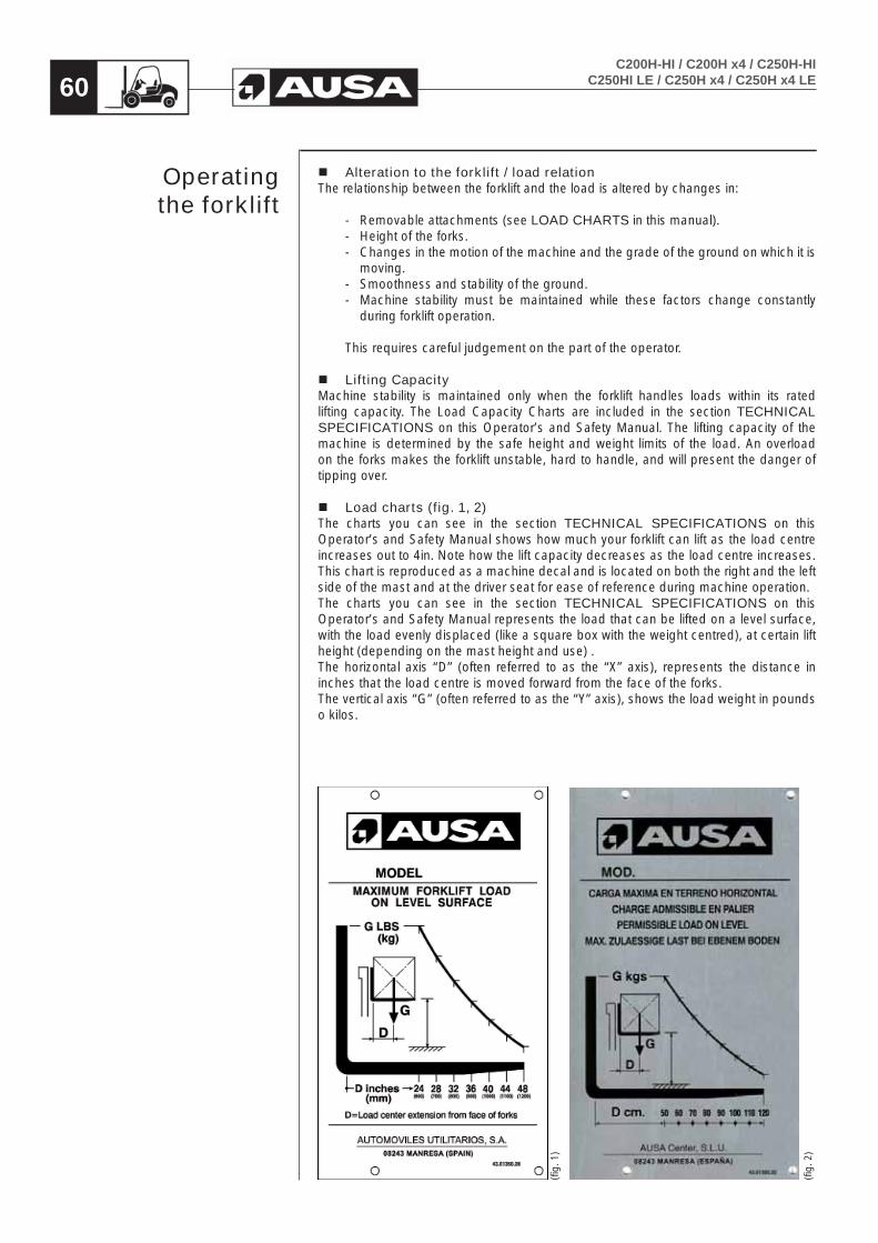
Load charts (fig. 1, 2)The charts you can see in the section TECHNICAL SPECIFICATIONS on this Operator’s and Safety Manual shows how much your forklift can lift as the load centre increases out to 4in. Note how the lift capacity decreases as the load centre increases. This chart is reproduced as a machine decal and is located on both the right and the left side of the mast and at the driver seat for ease of reference during machine operation.The charts you can see in the section TECHNICAL SPECIFICATIONS on this Operator’s and Safety Manual represents the load that can be lifted on a level surface, with the load evenly displaced (like a square box with the weight centred), at certain lift height (depending on the mast height and use) .The horizontal axis “D” (often referred to as the “X” axis), represents the distance in inches that the load centre is moved forward from the face of the forks.The vertical axis “G” (often referred to as the “Y” axis), shows the load weight in pounds o kilos.
Operatingthe forklift
(fig.
1)
(fig.
2)

C200H-HI / C200H x4 / C250H-HIC250HI LE / C250H x4 / C250H x4 LE 61
Engine overheatingIf the engine overheats and the engine temperature warning light on the control panel lights up, try the following:
- Check and clean the radiator coolant blades. See the section PERIODIC MAINTENANCE OPERATIONS in this Operator’s and Safety Manual.
- Slow down the speed but keep the forklift moving in order to allow air to circulate around the radiator.
- If the engine is still overheating after approximately one minute, stop driving the forklift, set the forward / backwards directional travel control switch to neutral, apply the parking brake and stop the engine.
WARNING
The radiator may be extremely hot. Use gloves before touching the radiator.
- Allow the engine to cool down. Check the coolant level and refill if necessary.
- If the engine continues to overheated, pls. contact to an authorized AUSA dealer as soon as possible.
After-use careWhen the forklift is used in salt water areas (beach areas, etc.), rinse the machine with fresh water to protect the forklift and its components from rust. We recommend lubricating the metal components. This should be carried out at the end of every day after using the forklift.When the forklift has been working in muddy areas, it should be washed with fresh water to protect the forklift and keep the lights clean.
Note: Never use high-pressure water to clean the forklift. ONLY USE LOW-PRESSURE WATER. High-pressure water may cause electrical and mechanical damage.
Rolling over (fig. 1)In the event of the machine rolling over it is important that the driver avoids being caught between the machine and the ground.To prevent this we recommend:
1. Try to remain within the seated operator area / cabin.2. Grasp the steering wheel firmly.3. Push feet, firmly, against the ground floor of the cabin.4. Try to keep as far away from the point of impact as possible.
(fig.
1)
Special procedures

C200H-HI / C200H x4 / C250H-HIC250HI LE / C250H x4 / C250H x4 LE62
When the forklift overturns or is knocked onto one side, restore it to normal operating position (on all four wheels).
WARNINGDO NOT TRY TO START THE FORKLIFT without first checking with an authorized AUSA dealer.
- Remove the four glow plugs.
- Turn the key in the ignition to position (c). Hold the key in position until the oil has come out of the combustion chamber.
WARNINGThe oil will come out of the combustion chambers at high pressure and may cause injury.
- Re-assemble the four glow plugs.
- Check the engine oil level and refill if necessary.
- If the engine oil pressure warning light remains lit after starting the engine, stop immediately to prevent internal damages and refer contact to an authorized AUSA dealer as soon as possible.
Immersion of the forkliftIf the forklift becomes submerged under water, it will be necessary to take it to an authorized AUSA dealer as soon as possible.
CAUTIONDO NOT START THE ENGINE. Immersion of the forklift may cause serious damage to the engine if the start-up procedures are not followed correctly.
- Arrange for an authorized AUSA dealer to carefully inspect the supply system as shown in the MAINTENANCE CHART.
Storage and pre-parking preparation.When the forklift is not to be used for more than a month it should be stored correctly.When the forklift is brought out for use again after a period of storage, special preparation is required. Ask an authorized AUSA dealer about the appropriate procedures.
Special procedures

C200H-HI / C200H x4 / C250H-HIC250HI LE / C250H x4 / C250H x4 LE 63
Tilting the mast while the engine is stopped (emergency movement)It is possible to tilt the mast of the forklift (emergency movement) forwards with the ignition off. To do so, proceed as follows:
- Locate the emergency movement connector under the dash panel, next to the steering column (fig. 1)
- Remove the protective cover from the connector by lifting the locking tab and moving it forwards.
- With the help of an external battery supply the connector with + 12V DC and earth (-) as follows:
Connector, contact 1: + 12V DCConnector, contact 2: earth (-)
- Push the joystick to the right in order to tilt the mast.
NOTETo help this movement, we recommend applying a small load on the end of the forks.
(fig.
1)
Special procedures

C200H-HI / C200H x4 / C250H-HIC250HI LE / C250H x4 / C250H x4 LE64
WARNINGDo not operate this machine unless you have read and understand the safety and operational instructions contained in this Operator’s and Safety Manual and have been instructed and trained in the safe operation of this Forklift. REMEMBER THAT “YOU” ARE THE KEY TO SAFETY.
General comments
Operator responsibilitiesBefore using the forklift that is initially unfamiliar, you should read the Operator’s and Safety Manual carefully and resolve any doubts with a supervisor (fig. 1). It is your responsibility to read and understand this Operator’s and Safety Manual before operating any rough terrain forklift. This Operator’s and Safety Manual takes you step by step through your working day.In order to help you better understand the text, graphics have been provided in this Operator’s and Safety Manual.It’s important that you know and apply all applicable laws and rules including OSHA requirements for operator training and certification.The forklift must only be used by authorized and correctly trained personnelAUSA manufactures its forklifts in accordance with ASME B56.6 and the corresponding International Standards.The Occupational Safety and Health Administration (OSHA) enforces federal laws that apply to safety of operation, application and maintenance of equipment on a worksite. Because it is an employer’s responsibility to apply these laws, an OSHA representative may periodically inspect a worksite to see that these laws are being followed. There may also be local or state/provincial laws that apply to this equipment and its use along with specific worksite or employer rules. It is important that you know and apply all applicable laws and rules.Any danger resulting from improper use, not complying with these provisions or others which are specifically provided with the machinery, shall be the responsibility of the user and not of AUSA. This section provides instructions on the use of the forklift, in accordance with that established by ASME B56.6, 2006/42/EC standard and OSHA documents.
Description of a forklift truckA forklift truck is a powered vehicle used for transporting or handling loads with the aid of tools specific to the task to be carried out. The forklift is able to lift loads. It consists of a resistant chassis resting upon two axles. The front axle is the drive axle and the rear axle the steering axle, although versions exist in which both axles are driving axles.At the front of the forklift there is a mast, along it moves the front carriage. The unit formed by both is designed to lift and tilt the load forwards and backwards, making handling easier
(fig.
1)
Special SafetyMessages

C200H-HI / C200H x4 / C250H-HIC250HI LE / C250H x4 / C250H x4 LE 65
General recommendations for driving a forklift truck
Basic information for starting up a forklift truckEntering and leaving the operator cabin, do not hold or pull the steering wheel to enter the driver cabin, use the handles provided on the front structure of the overhead guard. Always place one foot on the tread of the sill to prevent slipping when climbing in or out (fig. 1).Never start or operate any of the controls unless seated on the driver’s seat.Keep the driver’s cab free of objects and tools. These may move around, block a control or a pedal, and prevent a manoeuvre or stop the forklift.Before starting to work with the forklift, clean any oil or fuel spills, clean and remove grease from hands and the soles of shoes (fig. 2). Do not forget to carry out the operations and daily checks listed in the MAINTENANCE CHART on this Operator’s and Safety Manual.Check the correct position and fastening of all the guards, caps and safety stops.Check that all the controls are operating correctly.Check that informative and safety plates on the forklift are clean and in good condition. If they are not in good condition, replace them.Wear suitable protective that will protect you in the working environment. This may include a helmet, ear plugs, protective goggles or reflective clothing (fig. 3). Do not wear loose clothing or jewellery or long hair as these could become entangled in the controls, in moving parts or edges of the machine and prove dangerous.If working in an enclosed area make certain there is sufficient ventilation to prevent excessive build-up of exhaust fumes. Under this conditions always stop this engine when not in use.Before starting the forklift be certain to check or test the following items:
- Check for any leaks in the fuel, hydraulic or cooling system.- Clean any oil or fuel leaks that may exist on the forklift controls or operating area.- Check tire conditions and pressures.- Re-tight wheel nuts if necessary.- Check that all controls are working correctly.- Check the operator seat belt and its attachments. Ensure seat belt is properly latched. Inspect carefully the condition of this security
system with special attention to:- cuts or damages in the belt.- wear or damages in the metallic parts including the anchorage elements.- badly functioning of the buckle.- seams or free points of sewing.
Check brake pedal travel and effectiveness.Check the following fluid levels:
- Fuel- Braking fluid- Hydraulic fluid- Cooling system fluid- Engine oil
Check the horn.Check that lighting and signalling systems are clean and work correctly. If they do not work check the corresponding fuses and bulbs as shown in “Maintenance Operations” on this Operator’s and Safety Manual.
Jumping on or off the forklift can cause serious injury. Always face the machine and use rails and steps to slowly get on and slowly get off the forklift.Adjust seat position so you are comfortable and can easily reach all the controls. Now fasten your seat belt.Always stop the engine and do not smoke when fuelling the machine. (fig. 4) Follow the instructions given in the section “Fuel” on this Operator’s and Safety Manual.
(fig.
4)
(fig.
3)
(fig.
2)
(fig.
1)
Special SafetyMessages

C200H-HI / C200H x4 / C250H-HIC250HI LE / C250H x4 / C250H x4 LE66
Before starting and operating the forklift- Stay alert. Concentrate fully on your work. Your safety and that of others depends
on the care you take when operating this forklift.- Remember that you are the key to safety. Good safety practices not only protect
you but also the people around you.
The surrounding areaBe careful around any pedestrians in the surrounding areaThis forklift was designed to lift loads not people. Never transport people on any part of the forklift. Do not let people ride on the forks (fig. 1).Do not let people stand or walk under raised forks, loaded or unloaded (fig. 2).Give way to the right to pedestrians found in your path.Do not drive rapidly. Driving too fast is dangerous to the driver and to the load. The speed at which the forklift is operated should always be suited to the working conditions and to the space available for manoeuvring.Always drive smoothly and not in a jerky fashion.Never put any part of your body between the fork mast and the forklift body. (fig. 3).Be careful around any load edges, pressure zones or revolving movements and extensions.Be certain you have good visibility at all times. It is important that you can see clearly both forward and backward when operating the forklift. If the load does not allow clear forward visibility, then drive with caution in reverse. (fig. 4).This forklift is not designed to be used as a tow truck or tow vehicle. However if the forklift is to be towed to or from work location, see the section “Towing the forklift” on this Operator’s and Safety Manual.
Work circuitThe movement of loads within an installation or enclosure must be carried out following certain instructions concerning the circulation of forklifts and pedestrians. If you are not aware of these regulations, please check with your supervisor. Study the movements of the forklift to avoid making manoeuvres which are unnecessary, or involve risk to the surrounding areas. Find out which paths are suited to the type of vehicle you are driving and the load carried. If it is necessary to drive along public highways, first check that the forklift complies with current regulations of the country. Highway use of this off-road equipment may be restricted or prohibited by the laws of a State or Province.
Work cycleIf it is necessary to move loads continuously and repeatedly, try to do so with the minimum number of movements necessary, where possible. Reducing the number of movements saves fuel and reduces the emission of exhaust fumes. If the work is very intense, remember to check the instrument panel from time to time, especially in extreme climates, as the engine will be working in particularly hard conditions.
Forklift truck circulationWhen approaching a junction with poor visibility, reduce speed, emit acoustic warnings and proceed slowly according to the available visibility.The speed of the forklift should at all times be adapted to the working conditions and the surrounding area. Systematically driving at the maximum speed permitted by the machine may put the operator and the surrounding area at risk.
(fig.
4)
(fig.
3)
(fig.
2)
(fig.
1)
Special SafetyMessages

C200H-HI / C200H x4 / C250H-HIC250HI LE / C250H x4 / C250H x4 LE 67
Driving in reverseEnsure good visibility of the path to be taken. If the load being carried obstructs visibility, drive in reverse with the utmost of caution.Before reversing, the operator should ensure that this does not involve risks for the forklift, people or objects in the surrounding area (fig. 1).
Driving on gradientsSpecial care should be taken when driving on gradients: move slowly, avoid placing the machine across the gradient and do not work on higher gradients than those recommended.The maximum permitted gradient does not imply that it is possible to manoeuvre here in absolute safety under full load, ground and operating conditions.Gradients should be descended in reverse, with the load facing the direction of greatest stability (fig. 2).
Rudiments of static equilibriumIn order that the forklift is able to handle loads in a stable and safe manner, certain equilibrium conditions must exist and be maintained between the load and the machinery. Therefore, the forklift is fitted with counterweights at the rear. These are designed to compensate for the weight of the load being carried, as long as the centre of gravity of the load and the forklift are within certain established limits. In order to calculate the values of the transportable weight and the position of the centre of gravity permitted for the forklift see the Load Charts in the section “Operating the Machine” on this Operator’s and Safety Manual .
Rudiments of dynamic equilibriumWhile the forklift is moving, and as it gains speed, the equilibrium conditions of the load-forklift unit are modified as the centre of gravity shifts. This is accentuated on lifting loads, turning, braking, etc. In these conditions it is necessary to take the utmost care to ensure that the centre of gravity of the load is maintained within the specifications showed on the load chart plate.
Static equilibrium of a conventional forkliftThe forklift counterweight produces a situation of imbalance when the forklift is unloaded. The centre of gravity is maintained low and close to the rear of the forklift. When the load is collected, the imbalance is corrected and the centre of gravity shifts forward. If the load is within the margins given on the load chart, equilibrium is maintained. As the load is lifted, the centre of gravity also rises, shifting upwards. At the moment that the centre of gravity shifts beyond the forklift, the equilibrium is lost and the forklift becomes unstable. Therefore, the forklift should not move while the load is raised.
StabilityDo not carry unstable or loose loads, or loads which are oversized with respect to the forklift. If very large or wide loads must be carried, every precaution must be taken to prevent bumps or other possible accidents. When carrying out lifting manoeuvres, particularly at height, ensure that the forklift is on stable ground as levelled as possible.Do not drive over objects which may endanger the stability of the machine.
(fig.
2)
(fig.
1)
Special SafetyMessages

C200H-HI / C200H x4 / C250H-HIC250HI LE / C250H x4 / C250H x4 LE68
The triangle of horizontal stabilityTo prevent the loads which are being transported from falling, it is necessary to consider the triangle of horizontal stability (fig. 1). This is an imaginary inverted triangle, with the lower end located on the centre of the rear axle and the two upper vertices on each of the front wheels. Stability is guaranteed when the centre of gravity of the combination load (c)+ machine (m) remains within the limits of this imaginary triangle.
Longitudinal stabilizationThe risk of longitudinal overturning increases if the forklift is driven while the load is raised. Sharp braking and accelerating or rapid tilting movements decrease stability.
Transversal stabilityThe risk of overturning sideways increases on turning at incorrect speeds, while the forklift is unloaded or when the load is raised. Rough ground, sharp braking or accelerating or shifts in the load make these conditions worse.
Centre of gravity and the capacity of the forklift truckDo not overload the forklift or handle loads which shift the centre of gravity beyond that for which it is designed. Manoeuvre slowly, especially when changing direction on slippery ground .Do not handle loads that are unstable, loose or disproportionate to the size of the forks and the forklift machine itself. Make certain that long or wide loads are fastened together so as to be stable and secure.
The load and counterweightThe load should be lifted and lowered with the mast in vertical position or slightly tilted backwards. The raised load should only be tilted forwards when it is about to be unloaded.Tilting the load forwards or backwards (swinging) is very useful for collecting or positioning the load, but affects the longitudinal and lateral stability. Therefore, when handling raised loads, do not swing the mast more than is absolutely essential.The forklift may tip forwards when carrying a raised load with the mast tilted forwards, or in the event of sudden braking or accelerating while the load is raised. If using an accessory, attachment or tool, first check the permitted load. The combination of the weight of the forklift plus the weight of the accessory or attachment reduces the nominal load.
WARNINGThis forklift is not designed to travel with elevated load or with the mast tilted forward.Do not tilt forward the mast with the forks elevated except to pick up or deposit the load.The fully forward tilting mast angle is only intended to transport the forklift on a truck bed, always without load.For operating with load do not exceed 10º for the forward tilting mast angle.
(fig.
1)
Special SafetyMessages
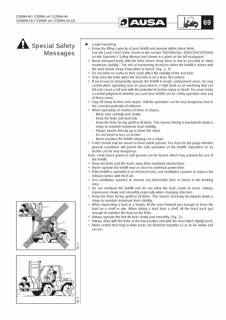
C200H-HI / C200H x4 / C250H-HIC250HI LE / C250H x4 / C250H x4 LE 69
Load handling• Know the lifting capacity of your forklift and operate within those limits. See the Load Limit Charts shown in the section TECHNICAL SPECIFICATIONS
on this Operator’s Safety Manual and shown in a plate on the left mudguard.• Never transport loads with the forks raised -keep them as low as possible to attain
maximum stability-. The risk of overturning increases when the forklift is driven with the load raised. Keep it low when in transit. (fig. 1, 2)
• Do not drive on surfaces that could affect the stability of the machine. • Only raise the forks when the machine is on a level, flat surface.• If necessary to temporarily operate the forklift in rough, unimproved areas, be very
careful when operating near an open trench, a high bank or an overhang that can fall and cause a roll over with the potential of serious injury or death. You must make a careful judgement whether you and your forklift can be safely operated near any of these areas.
• Stay off steep inclines and slopes. Hillside operation can be very dangerous due to the constant potential of rollovers.
• When operating on modest inclines or slopes: - Move very carefully and slowly.- Keep the forks and load low.- Keep the forks facing uphill at all times. This means driving in backwards down a
slope to maintain maximum load stability.- Always travels directly up or down the slope.- Do not travel across an incline.- Never position the forklift sideways on a slope.
• Forks should only be raised on level stable ground. You must be the judge whether ground conditions will permit the safe operation of the forklift. Operation on an incline can be very dangerous.
Rain, snow, loose gravel or soft ground can be factors which may prevent the use of the forklift.
• Keep the forks and the loads away from overhead obstructions.• Never operate the forklift near or close to overhead power lines.• If the forklift is operated in an enclosed area, use ventilation systems to replace the
exhaust fumes with fresh air.• Use ventilation systems to remove any flammable dust or steam in the working
area.• Do not overload the forklift and do not allow the load centre to move. Always
manoeuvre slowly and smoothly especially when changing direction.• Keep the forks facing uphill at all times. This means reversing backwards down a
slope to maintain maximum load stability. • When depositing a load to a height, tilt the mast forward just enough to leave the
load on a shelf or pile. When taking a load from a shelf, tilt the mast back just enough to stabilise the load on the forks.
• Always operate the fork tilt lever slowly and smoothly. (fig. 2).• Always drive with the forks in the low position and with the mast tilted slightly back.• Make certain that long or wide loads are fastened together so as to be stable and
secure.
(fig.
1)
(fig.
2)
Special SafetyMessages

C200H-HI / C200H x4 / C250H-HIC250HI LE / C250H x4 / C250H x4 LE70
Critical speedThe speed at which the forklift moves affects its stability. When turning, braking, or accelerating, the centre of gravity shifts within the triangle of stability. Sharp turns, sudden braking or accelerating cause the centre of gravity to shift sharply and it may fall outside the triangle. This is the moment when the stability of the forklift and the load are not guaranteed and there is a risk of accident.When manoeuvring reduce the speed of the forklift and avoid turning the steering wheel sharply.Do not drive the forklift at a fast speed and then attempt a turn as the forklift may tip over. Always drive slowly when making a turn and keep the forks low when turning (fig. 1).
Accesses and doorsMake sure that the passages and doors along the route are sufficiently high to allow all the forklift to pass.When carrying out lifting manoeuvres, pay special attention to the height of the roof, lighting and other overhead installations.
Ground surfaceCheck that the ground is strong enough to bear the forklift when loaded, especially when approaching bridges, the edges of embankments, concrete floors elevators, etc. (fig. 2).
LightingThe forklift working area should be adequately lit to prevent the risk of accident, running over persons or colliding with obstacles. As soon as the daylight fades, the forklift lighting system should be switched on. If the forklift is not equipped with lighting, make sure that the working area is adequately lit. If this is not possible, do not continue working with the forklift, this may result in an accident.
Loading bay. Communication. Shelving and installations. The loadThe loading bay or area where the loads are handled should be correctly equipped and signposted. The operating area of the forklift should be free of obstacles and pedestrians, however if their presence is necessary, the pedestrians should move in areas which have been duly marked as such and they should be easily distinguished, for example, by wearing reflective jackets.If the area is closed it should be well-ventilated and the forklift must be equipped with lighting and exhaust gas purifier systems. The forklift operator should be able to communicate normally with pedestrians. If the surrounding area is excessively noisy, pedestrians should refrain from walking in the immediate vicinity. If this is unavoidable, the utmost care should be taken. Radio communication equipment should not be handled while driving the forklift. If it is necessary to use the radio, pull over to one side and signal the position of the forklift, using the lights or hazard warning lights.Shelving for the loads have a series of marked passageways. The width of these should be at least the width of the forklift plus 40 in (1 m). If the passageway is two-way, the width must be sufficient to allow two forklifts to pass plus an additional 55 in (1,5 m).Before using the forklift to handle loads check the load and ensure that the weight does not exceed the forklift capacity. At the same time, check that the load is stabilized and correctly secured, to ensure that no part of the load falls off during transportation.
(fig.
2)
(fig.
1)
Special SafetyMessages

C200H-HI / C200H x4 / C250H-HIC250HI LE / C250H x4 / C250H x4 LE 71
Order and cleanlinessCarrying out a series of checks before starting the forklift and keeping the operator cab clean help to make the work safer. To do so, follow the MAINTENANCE CHART given in this Operator’s and Safety Manual strictly, and keep the operator cab clean and free of earth, gravel, mud, oil or other objects which may cause falls.Do not carry objects in the operator cab. These may injure the operator or accidentally activate the forklift controls.
Overhead Guard
WARNINGYou are protected by an overhead guard which complies with the provisions of ISO 3449 and ISO 3471 / ASME B56.6. It protects the operator against falling objects and, together with the mast, gives protection to the operator in the event of an accidental tip over. The seat belt is an important part of this safety system and must always be fastened before operating the forklift.Failure to wear the seat belt in the event of an accidental tip over could result serious injury or death as you could be crushed by the machine or by the overhead guard.
The above decal is located on the side of the machine. Overhead Guard must be weekly inspected for excessive damage cracks permanent deformation or signs of potential cracks. If these incidents appear, structure must not be repaired but replaced for a new one.
When leaving / parking the forklift (fig. 1, 2, 3)A poorly parked forklift truck is a risk.Park the forklift in the areas provided for this purpose, without obstructing the passage of others, exits or entrances to stairs and emergency equipment.
• Place the forks or attachment in the fully lowered position.• Set all the controls in the “0” neutral position.• Apply the parking brake.• Do not park the forklift on a slope. If it is necessary to park the forklift on a gradient,
in addition to using the parking brake, place chocks against the wheels.• Stop the engine and cut the ignition circuit. Remove the ignition key.• Lock all mechanisms to prevent any unauthorised person from using the machine.• Remember that you are the key to safety. Good safety practices not only protect
you but also the people around you.
(fig.
3)
(fig.
2)
(fig.
1)
Special SafetyMessages

C200H-HI / C200H x4 / C250H-HIC250HI LE / C250H x4 / C250H x4 LE72
Parking the machine and stopping the engineMake certain that the forklift is parked on level ground when leaving it overnight. Also park it on level ground before any scheduled maintenance is attempted.
- Lower the forks to the ground, apply the parking brake and push directional switch to neutral.
- Run the engine at idle for 1 minute if the engine has been working at full load -as this procedure will cool the engine components evenly.
- Turn off the key switch in a counter-clockwise motion to stop the engine.- Remove the key from the ignition and take it with you. Never leave the key
in a parked machine.
Be careful with the environmentAt the end of the operating life of the machine, bring it to a recycling center or an scrap-dealer.It is absolutely forbidden to leave the materials in public places.
When changing the engine oil or other fluids, use a big collecting trough. Make sure not to pollute the environment with emerging oil and other waste products (coolant, batteries, etc.) bring them to the corresponding recycling centre.In case that substances escape from the machine that are harmful to the environment and/or to the people, take remedial measures inmediately, (eg.: if hydraulic oil emerges; apply oil bonding agent, put a collecting vessel underneath, tighten leakage, remove and dispose of contaminated earth, if required).At the end of the life cycle of the machine, bring it to the specialised and recognised recycling centres.
Parking the machine

C200H-HI / C200H x4 / C250H-HIC250HI LE / C250H x4 / C250H x4 LE 73
Fastening the forklift to a lorry or trailer bed. (fig. 1, 2)When transporting the forklift on a trailer or truck bed, carefully follow the instructions in the Caution Decal. Move slowly and carefully up (or down) the loading ramps. Once on the trailer make certain the forks are lowered, handbrake applied and the forks and tires are blocked. Lastly make certain the forklift is securely tied down. After the machine has been positioned on the Lorry/Trailer bed, put chocks at the front and rear of the forklift tires.Firmly fast the forklift to the trailer or truck bed with chains, cable or tie-down straps to prevent any movement in the position shown in the picture 1.Use the four eyes welded on to the chassis of the forklift purpose (fig. 2)
WARNINGBefore you put the forklift on a trailer or truck bed, make certain that the ramp is strong enough to support the load and that the parking surface is fee of debris, oil, grease or ice.
• Do not transport the forklift with a full diesel fuel tank.• Make certain your seat belt is properly fastened. • Move the forklift slowly and carefully up the ramp onto the trailer.• Shift the directional control lever to neutral.• Apply the parking brake. • In transit position lower the forks to their lowest level.• Stop the engine and remove the key.• Put blocks under the tips of each fork and tilt the mast slightly forward.• Choks must be placed on all four wheels.• Fast the forklift to the lorry chassis using chains, straps or sling cablesof sufficiente strengh.
Loading onto a trailer by crane (fig. 3)lf a sling and crane are used to load the forklift onto a trailer or truck, attach the sling as shown in the next figure. Before lifting check that the sling cable is firmly attached. While lifting the forklift do not permit riders on the forklift or by standers within 15ft (5m).
To lift the machine with a crane, bear in mind the following advice: - Front slings must not be shorter than 8ft (2,5 meters).- Always raise the machine in a balanced position. - Keep the angle of inclination of the front sling approximately the same as the
angle of inclination of the mast.
(fig.
3)
(fig.
1)
(fig.
2)
Transportingthe machine

C200H-HI / C200H x4 / C250H-HIC250HI LE / C250H x4 / C250H x4 LE74
Towing the machineIf the machine must be towed for short distances, only do so with a solid tow-bar to prevent any lateral sway. Attach the tow bar to the bolt at the rear of the counter weight (fig. 1). Drive slowly and carefully at a speed not exceeding 6 mph (10 Km/h) and of maximum for a duration not exceeding 3 minutes.. Comply with all state laws governing the operation / towing of an off-highway machine on public roads and highways.
Before towing the machine:
Release the parking brake (fig. 2, 3, 4)In the event that the parking brake is blocked, due, for example, to a loss of brake fluid, or because the engine does not start, proceed as follows to release it.
Remove the bleeder (a) from the brake.Screw on the nipple (b)supplied in the forklift tool box.Using a hand pump lubricator (d) insert grease until the internal pressure manages to release the parking brake.Remove handbrake release pressure hose and plug in the fitting with a M12 x 1,5 mm. thread plug (c).To finally release the parking brake, unscrew the nipple (b). The grease will come out of the brake thanks to the operation of the internal springs.Re-assemble the bleeder (a).Disassemble plug (c) and connect handbrake hose again.
WARNINGAny repair to the brake system should be carried out by an authorized AUSA dealer.
CAUTIONNot plugging in handbrake hose fitting before inserting grease into the brake unit can lead to a hydrostatic pump damage. Contact your nearest AUSA dealer if you have any doubt.
(fig.
3)
(fig.
2)
(fig.
4)
(fig.
5)
(fig.
1)
Transportingthe machine
a
b
c
d
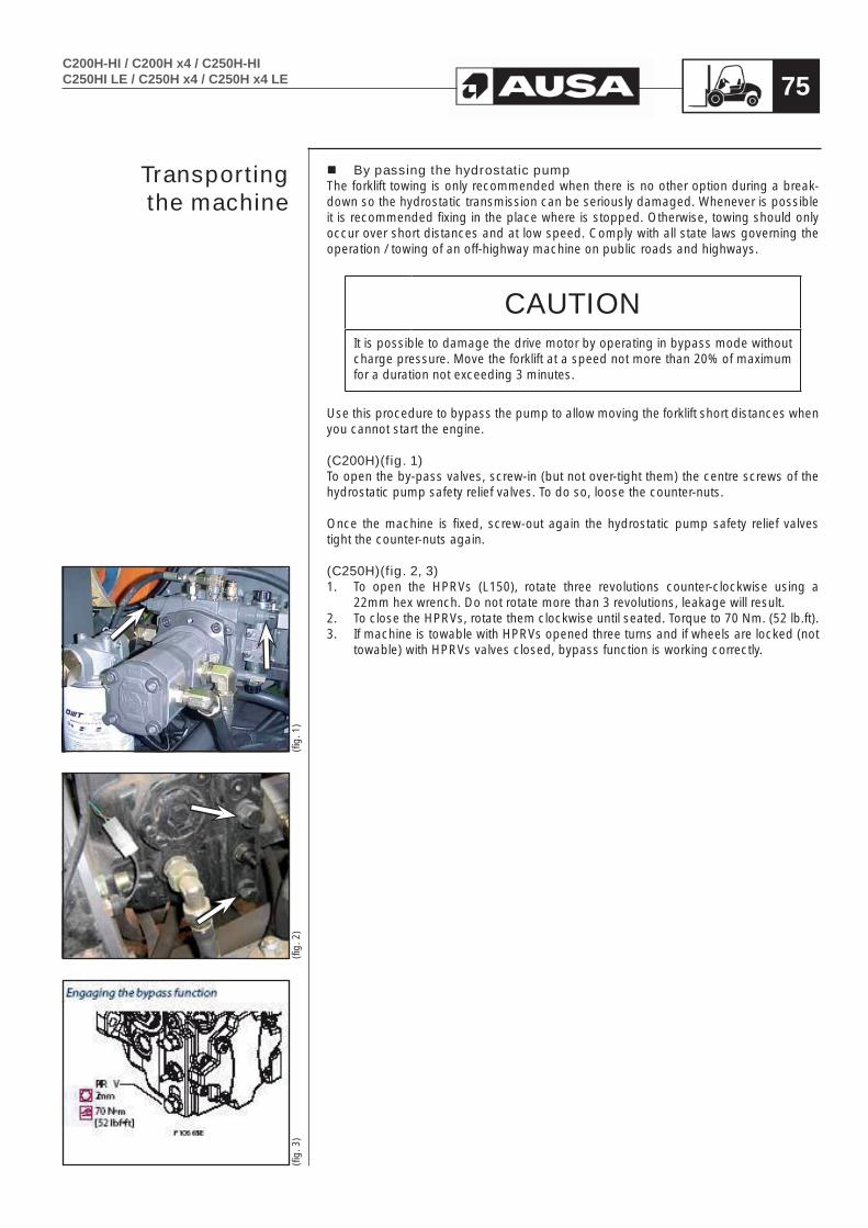
C200H-HI / C200H x4 / C250H-HIC250HI LE / C250H x4 / C250H x4 LE 75
By passing the hydrostatic pump The forklift towing is only recommended when there is no other option during a break-down so the hydrostatic transmission can be seriously damaged. Whenever is possible it is recommended fixing in the place where is stopped. Otherwise, towing should only occur over short distances and at low speed. Comply with all state laws governing the operation / towing of an off-highway machine on public roads and highways.
CAUTIONIt is possible to damage the drive motor by operating in bypass mode without charge pressure. Move the forklift at a speed not more than 20% of maximum for a duration not exceeding 3 minutes.
Use this procedure to bypass the pump to allow moving the forklift short distances when you cannot start the engine.
(C200H)(fig. 1)To open the by-pass valves, screw-in (but not over-tight them) the centre screws of the hydrostatic pump safety relief valves. To do so, loose the counter-nuts.
Once the machine is fixed, screw-out again the hydrostatic pump safety relief valves tight the counter-nuts again.
(C250H)(fig. 2, 3) 1. To open the HPRVs (L150), rotate three revolutions counter-clockwise using a
22mm hex wrench. Do not rotate more than 3 revolutions, leakage will result.2. To close the HPRVs, rotate them clockwise until seated. Torque to 70 Nm. (52 lb.ft). 3. If machine is towable with HPRVs opened three turns and if wheels are locked (not
towable) with HPRVs valves closed, bypass function is working correctly.
Transportingthe machine
(fig.
1)
(fig.
3)
(fig.
2)

C200H-HI / C200H x4 / C250H-HIC250HI LE / C250H x4 / C250H x4 LE76
This section specifi es the recommended liquid and lubricants. See the MAINTENANCE CHART on this Manual for the recommended change /
service intervals.FLUID OR
LUBRICANTSPECIFICATION REMARKS AUSA P/N
CAPACITY (Litres)
CAPACITY (US Gal.)
FUEL
Use clean auto diesel (class A), preferably in accordance with
Directive 98/70/EEC modified by directive 2003/17 or Standard
EN 590 equivalent to the same. In Spain this corresponds to RD 1728/1999. For the USA market, it should conform to Grades 1D and 2D of ASTM D975 and for
supplies not conforming to these requirements, in no event should the sulphur content exceed 0.5% by mass. Initially, the use of REM
type biodiesel or similar is not recommended. In the event that
it is used, it should not be used in proportions higher than 5 % of the
fuel mixture
50 13,2
ISUZU 4LE2 ENGINE OIL
Engine oil in accordance with MIL- 2104C / API CD or higher
See section“ENGINE OIL”in this section
461.00099.01
8,1 2,1
KUBOTA V2403-M
ENGINE OIL9,5 2,51
ENGINE COOLANT
Ethylene glycol antifreeze with corrosion inhibitors for aluminum engines with internal combustion. 50% glycol / 50% distilled water in
Standard machine.
See section“ENGINE COOLANT”
in this section45.00075.01 7 1,8
HYDRAULIC CIRCUIT
Hydraulic oil ISO Grade VG-46 in accordance with ISO 6743/4 HV DIN 51524 Part 3 - class HVLP
461.00099.06 45 11,9
FRONT AXLE DIFF. Transmission oil SAE 90 in
accordance with API GL5 / MIL L-2105D with additive, “LIMITED
SLIP”
See section“OIL FOR COMPEN, FULL GRIP () AND
FRONT AXLE”in this section
461.00099.09
4 1
FINAL DRIVE ON THE
FRONT AXLE 0,4 0’10
REAR AXLE DIFF. 4x4
Transmission oil SAE 90 inaccordance with API GL5 / MIL
L- 2105B 461.00004.01
3,3 0,9
FINAL DRIVE ON REAR AXLE 4x4
0,3 0,08
TRANSFER BOX 4x2
1,4 0,35
TRANSFER BOX 4x4
(COMPEN AND FULL GRIP)
AUSA COMPEN OIL
See section“OIL FOR COMPEN, FULL GRIP () AND
FRONT AXLE”in this section
461.00099.09 2,75 0,7
BRAKE FLUID AND INCHING
SAE 10W Hydraulic Oil or ATF fl uid in accordance with CAT TO-4
/ TO-2 o ALLISON C-4 / C-3.
See section“BRAKE FLUID AND INCHING”
inthis section
461.00099.07 1 0’25
WINDSCREEN WIPER
WASHER Freezing point
temperature: - 20ºC 465.00016.00 1,5 0,4
BATTERY ELECTROLYTE
Distilled Water
See section “BATTERY
ELECTROLYTE”in this section
GREASING POINTS
Calcic grease NLGI-3 consistency
See section“LUBRICATION
POINTS”in this Operator’s
Manual
461.00009.00
Recommended fluids and lubricants
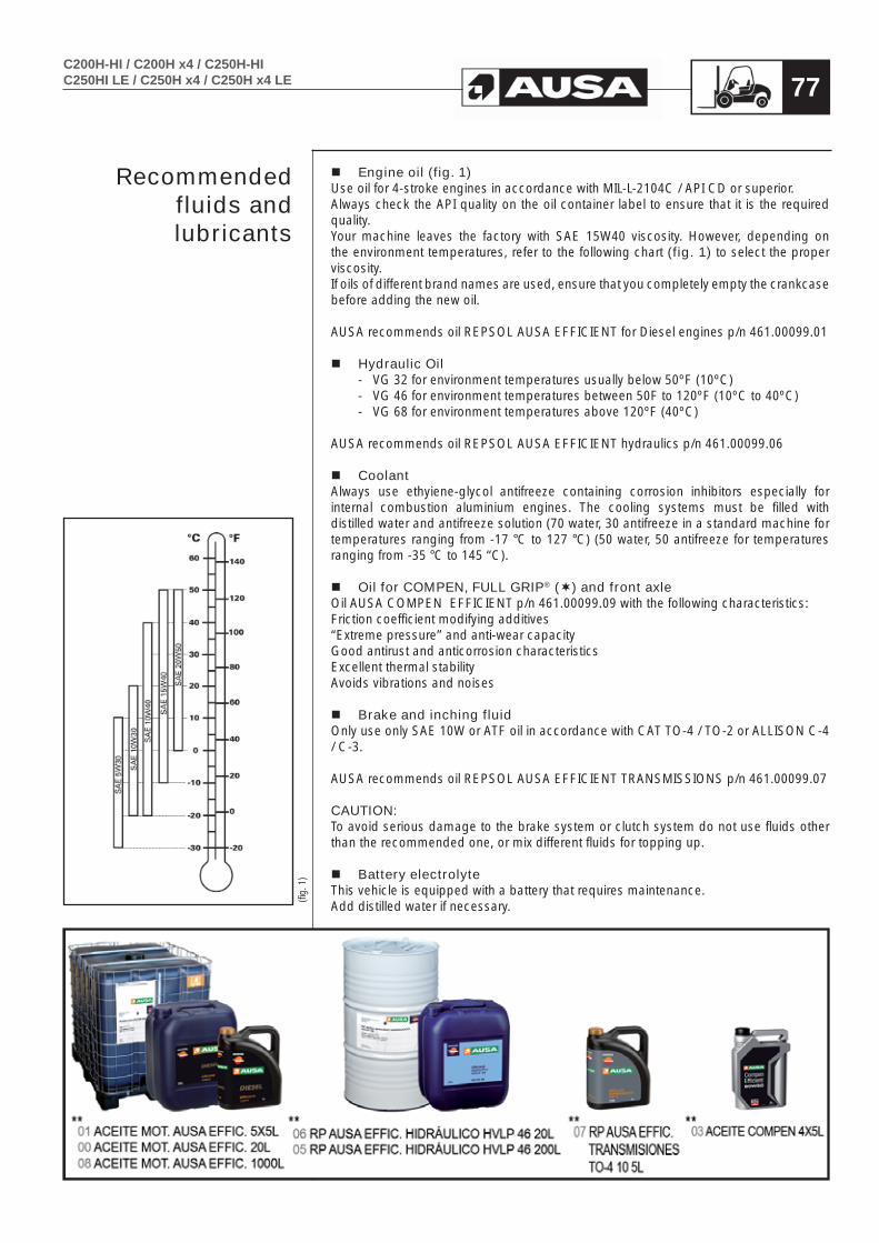
C200H-HI / C200H x4 / C250H-HIC250HI LE / C250H x4 / C250H x4 LE 77
Engine oil (fig. 1)Use oil for 4-stroke engines in accordance with MIL-L-2104C / API CD or superior.Always check the API quality on the oil container label to ensure that it is the required quality.Your machine leaves the factory with SAE 15W40 viscosity. However, depending on the environment temperatures, refer to the following chart (fig. 1) to select the proper viscosity. If oils of different brand names are used, ensure that you completely empty the crankcase before adding the new oil.
AUSA recommends oil REPSOL AUSA EFFICIENT for Diesel engines p/n 461.00099.01
Hydraulic Oil- VG 32 for environment temperatures usually below 50ºF (10ºC)- VG 46 for environment temperatures between 50F to 120ºF (10ºC to 40ºC)- VG 68 for environment temperatures above 120ºF (40ºC)
AUSA recommends oil REPSOL AUSA EFFICIENT hydraulics p/n 461.00099.06
CoolantAlways use ethyiene-glycol antifreeze containing corrosion inhibitors especially for internal combustion aluminium engines. The cooling systems must be filled with distilled water and antifreeze solution (70 water, 30 antifreeze in a standard machine for temperatures ranging from -17 °C to 127 °C) (50 water, 50 antifreeze for temperatures ranging from -35 °C to 145 “C).
Oil for COMPEN, FULL GRIP® () and front axleOil AUSA COMPEN EFFICIENT p/n 461.00099.09 with the following characteristics:Friction coefficient modifying additives “Extreme pressure” and anti-wear capacityGood antirust and anticorrosion characteristicsExcellent thermal stabilityAvoids vibrations and noises
Brake and inching fluidOnly use only SAE 10W or ATF oil in accordance with CAT TO-4 / TO-2 or ALLISON C-4 / C-3.
AUSA recommends oil REPSOL AUSA EFFICIENT TRANSMISSIONS p/n 461.00099.07
CAUTION:To avoid serious damage to the brake system or clutch system do not use fluids other than the recommended one, or mix different fluids for topping up.
Battery electrolyteThis vehicle is equipped with a battery that requires maintenance.Add distilled water if necessary.
Recommended fluids and lubricants
(fig.
1)
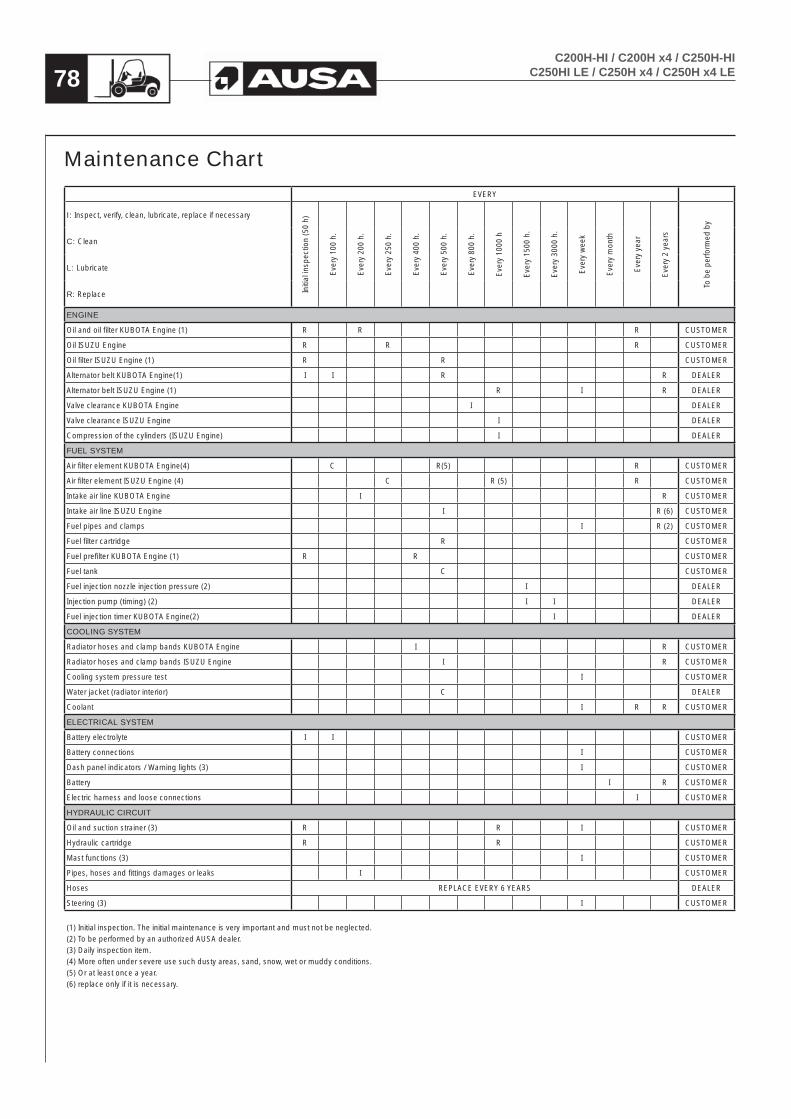
78C200H-HI / C200H x4 / C250H-HI
C250HI LE / C250H x4 / C250H x4 LE
Maintenance ChartEVERY
I: Inspect, verify, clean, lubricate, replace if necessary
Initi
al in
spec
tion
(50
h)
Eve
ry 1
00 h
.
Eve
ry 2
00 h
.
Eve
ry 2
50 h
.
Eve
ry 4
00 h
.
Eve
ry 5
00 h
.
Eve
ry 8
00 h
.
Eve
ry 1
000
h
Eve
ry 1
500
h.
Eve
ry 3
000
h.
Eve
ry w
eek
Eve
ry m
onth
Eve
ry y
ear
Eve
ry 2
yea
rs
To b
e pe
rform
ed b
y
C: Clean
L: Lubricate
R: Replace
ENGINE
Oil and oil filter KUBOTA Engine (1) R R R CUSTOMER
Oil ISUZU Engine R R R CUSTOMER
Oil filter ISUZU Engine (1) R R CUSTOMER
Alternator belt KUBOTA Engine(1) I I R R DEALER
Alternator belt ISUZU Engine (1) R I R DEALER
Valve clearance KUBOTA Engine I DEALER
Valve clearance ISUZU Engine I DEALER
Compression of the cylinders (ISUZU Engine) I DEALER
FUEL SYSTEM
Air filter element KUBOTA Engine(4) C R(5) R CUSTOMER
Air filter element ISUZU Engine (4) C R (5) R CUSTOMER
Intake air line KUBOTA Engine I R CUSTOMER
Intake air line ISUZU Engine I R (6) CUSTOMER
Fuel pipes and clamps I R (2) CUSTOMER
Fuel filter cartridge R CUSTOMER
Fuel prefilter KUBOTA Engine (1) R R CUSTOMER
Fuel tank C CUSTOMER
Fuel injection nozzle injection pressure (2) I DEALER
Injection pump (timing) (2) I I DEALER
Fuel injection timer KUBOTA Engine(2) I DEALER
COOLING SYSTEM
Radiator hoses and clamp bands KUBOTA Engine I R CUSTOMER
Radiator hoses and clamp bands ISUZU Engine I R CUSTOMER
Cooling system pressure test I CUSTOMER
Water jacket (radiator interior) C DEALER
Coolant I R R CUSTOMER
ELECTRICAL SYSTEM
Battery electrolyte I I CUSTOMER
Battery connections I CUSTOMER
Dash panel indicators / Warning lights (3) I CUSTOMER
Battery I R CUSTOMER
Electric harness and loose connections I CUSTOMER
HYDRAULIC CIRCUIT
Oil and suction strainer (3) R R I CUSTOMER
Hydraulic cartridge R R CUSTOMER
Mast functions (3) I CUSTOMER
Pipes, hoses and fittings damages or leaks I CUSTOMER
Hoses REPLACE EVERY 6 YEARS DEALER
Steering (3) I CUSTOMER
(1) Initial inspection. The initial maintenance is very important and must not be neglected.(2) To be performed by an authorized AUSA dealer. (3) Daily inspection item.(4) More often under severe use such dusty areas, sand, snow, wet or muddy conditions.(5) Or at least once a year. (6) replace only if it is necessary.

79C200H-HI / C200H x4 / C250H-HIC250HI LE / C250H x4 / C250H x4 LE
EVERY
I: Inspect, verify, clean, lubricate, replace if necessary
Initi
al in
spec
tion
(50
h)
Eve
ry 1
00 h
.
Eve
ry 2
00 h
.
Eve
ry 2
50 h
.
Eve
ry 4
00 h
.
Eve
ry 5
00 h
.
Eve
ry 8
00 h
.
Eve
ry 1
000
h
Eve
ry 1
500
h.
Eve
ry 3
000
h.
Eve
ry w
eek
Eve
ry m
onth
Eve
ry y
ear
Eve
ry 2
yea
rs
To b
e pe
rform
ed b
y
C: Clean
L: Lubricate
R: Replace
GREASING POINTS
Masts guides L CUSTOMER
Nipples (see section “Greasing points” in this Manual) L CUSTOMER
Cables and articulations (throttle, lifting rams...) L CUSTOMER
TRANSFER-BOX
Oil (1) R R I R CUSTOMER
Oil leaks I CUSTOMER
Screws and nuts torque I CUSTOMER
AXLES (FRONT AND REAR)
Oil (1) R R I R CUSTOMER
Oil leaks I CUSTOMER
Fixation wheel nuts torque I CUSTOMER
Chassis fixation screws (torque) I DEALER
Cardan joint fixation screws (torque) I DEALER
Flange fixation nut (torque) I DEALER
Condition of tires and pressures I CUSTOMER
BRAKES
Brake fluid (3) R I R CUSTOMER
Foot brake adjustment (3) I I DEALER
Handbrake adjustment I I DEALER
BODY / FRAME
Cabin I CUSTOMER
Seat belt (3) I CUSTOMER
Foot plate, access steps and handles (3) I / C CUSTOMER
Guards and covers (3) I CUSTOMER
Plates and decals (3) I / C CUSTOMER
Tipped cabin safety latch I CUSTOMER
Cabin lock I CUSTOMER
(1) Initial inspection. The initial maintenance is very important and must not be neglected.(2) To be performed by an authorized AUSA dealer. (3) Daily inspection item.(4) More often under severe use such dusty areas, sand, snow, wet or muddy conditions.(5) Or at least once a year. (6) replace only if it is necessary.
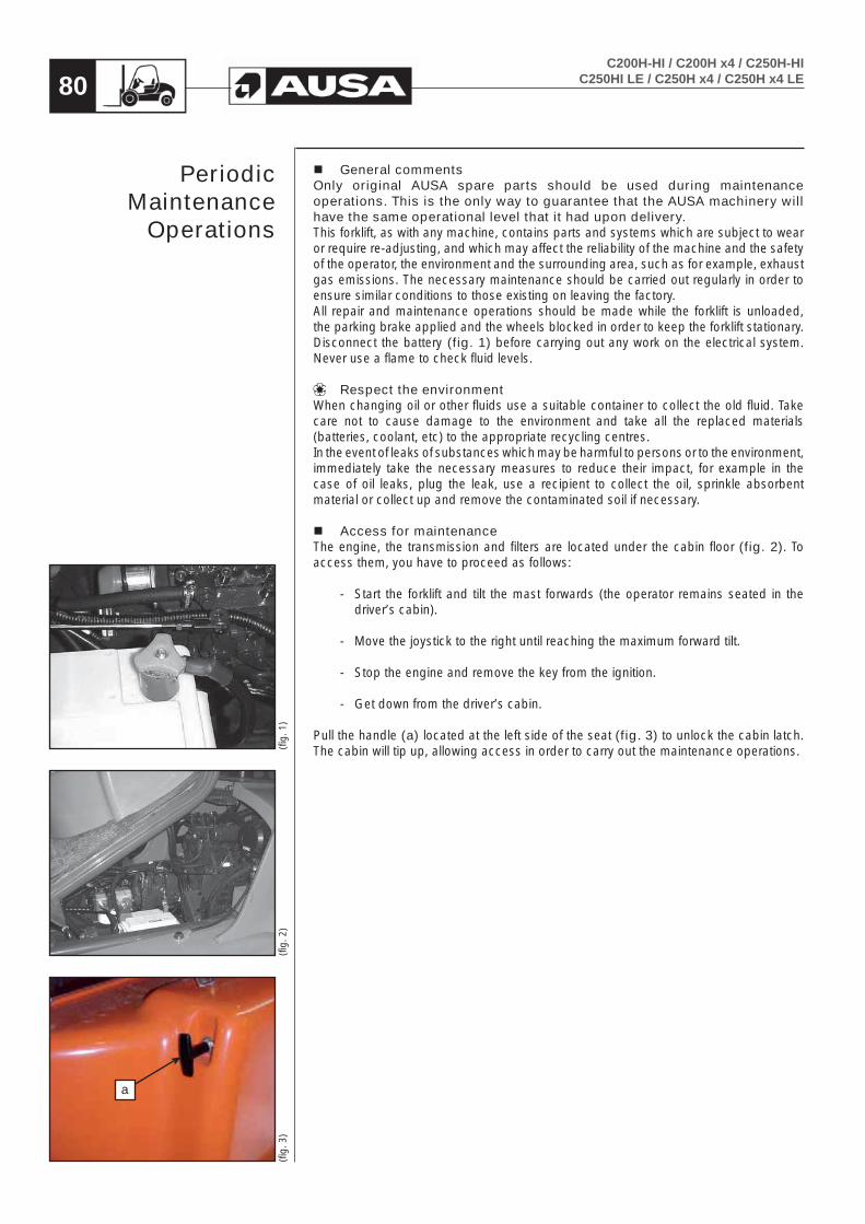
C200H-HI / C200H x4 / C250H-HIC250HI LE / C250H x4 / C250H x4 LE80
General commentsOnly original AUSA spare parts should be used during maintenance operations. This is the only way to guarantee that the AUSA machinery will have the same operational level that it had upon delivery. This forklift, as with any machine, contains parts and systems which are subject to wear or require re-adjusting, and which may affect the reliability of the machine and the safety of the operator, the environment and the surrounding area, such as for example, exhaust gas emissions. The necessary maintenance should be carried out regularly in order to ensure similar conditions to those existing on leaving the factory.All repair and maintenance operations should be made while the forklift is unloaded, the parking brake applied and the wheels blocked in order to keep the forklift stationary.Disconnect the battery (fig. 1) before carrying out any work on the electrical system. Never use a flame to check fluid levels.
Respect the environmentWhen changing oil or other fluids use a suitable container to collect the old fluid. Take care not to cause damage to the environment and take all the replaced materials (batteries, coolant, etc) to the appropriate recycling centres.In the event of leaks of substances which may be harmful to persons or to the environment, immediately take the necessary measures to reduce their impact, for example in the case of oil leaks, plug the leak, use a recipient to collect the oil, sprinkle absorbent material or collect up and remove the contaminated soil if necessary.
Access for maintenanceThe engine, the transmission and filters are located under the cabin floor (fig. 2). To access them, you have to proceed as follows:
- Start the forklift and tilt the mast forwards (the operator remains seated in the driver’s cabin).
- Move the joystick to the right until reaching the maximum forward tilt.
- Stop the engine and remove the key from the ignition.
- Get down from the driver’s cabin.
Pull the handle (a) located at the left side of the seat (fig. 3) to unlock the cabin latch. The cabin will tip up, allowing access in order to carry out the maintenance operations.
Periodic Maintenance
Operations
(fig.
3)
a
(fig.
2)
(fig.
1)

C200H-HI / C200H x4 / C250H-HIC250HI LE / C250H x4 / C250H x4 LE 81
After lifting up the cabin, it should be secured using the safety lock- CAB SAFETY PROP STOWED AWAY (fig. 1)- CAB SAFETY PROP LOWERED INTO POSITION (fig. 2)
WARNINGWhenever the cabin is raised, the safety lock must be on. This prevents the cabin from causing an accident on descending.
To access the sides of the engine, undo the bolt (a) and nut (b) (fig. 3) and remove the rear wheel cover. There is a wheel cover on each side of the machine.
Daily checks- Before starting to work with the forklift, clean any oil or fuel spills, clean and
remove grease from hands and the soles of shoes and do not forget to make the following checks:
- Condition of the lifting chains
- Tyre pressure and condition of the tread.
- Brakes.
- Leaks in the hydraulic, coolant, fuel circuits, etc.
- Check the correct position and fastening of all the guards, caps and safety stops.
- Absence of cracks or other structural defects visible at first glance.
- Check that all the controls are operating correctly.
- Check fluid levels:- fuel.- brake fluid.- hydraulic circuit fluid.- coolant circuit fluid.
- Check that alarm and signalling devices are operating correctly (for example: acoustic warning, air intake filter blocked warning, etc.)
- Check that informative and safety plates on the forklift are clean and in good condition.
- Clean and check lighting and signalling system are operating correctly.
- Check electrical battery connections and level of electrolyte.
- Adjust the seat to your build.
- Carefully inspect the condition of the seatbelt, paying special attention to:- Cuts or fraying on the belt.- Wear or damage to the fastenings including the anchorage points.- Poor functioning of the buckle or automatic reel device.- Loose stitching.
Correct any problems before using the forklift.Where necessary, refer the problem to an authorized AUSA dealer.
Periodic Maintenance
Operations
(fig.
3)
ab
(fig.
1)
(fig.
2)

C200H-HI / C200H x4 / C250H-HIC250HI LE / C250H x4 / C250H x4 LE82
Machine cleaning During the clean operations, not to direct pressure water on the intake (air filter), the steering column, battery, alternator and other electric devices because can deteriorate their components.
Breakdown in road (fig. 1)• In case of breakdown when driving on public roads, warn other users of the road
with the hazard warning triangles (). They could be stored under the cabin; raising it.
EngineFor operating instructions, list of spare parts and general maintenance, see the engine handbooks or the MAINTENANCE CHART.
Alternator beltCheck the tension of the alternator belt regularly. Also check for cracks or other damage. Ref er to an authorized AUSA dealer for the replacement of the alternator belt.
Engine oilOil level: Checking
With the forklift on a level surface, while the engine is cold and switched off, check the oil level as follows:
- Pull out the dipstick and clean on a clean cloth.
- Replace the dipstick in its casing.
- Remove again and check the oil level. This should be at the upper level. (fig. 2).
a- Fullb- Add oilc- Operating range
- Add oil until the level reaches the upper level.
Oil level: Correct
- Remove the dipstick and place a funnel in the opening of the oil filler neck located above the rocker arm cover.
CAUTIONDo not exceed the maximum level mark. Starting the engine with incorrect oil levels may cause serious damage. Clean up any spillage. Check the oil level often and top up where necessary.
- Top up with oil gradually until the level is correct.
(fig.
2)
(fig.
1)
Periodic Maintenance
Operations

C200H-HI / C200H x4 / C250H-HIC250HI LE / C250H x4 / C250H x4 LE 83
Engine oil: Draining
The oil change should be made when the oil is warm.
WARNINGThe engine oil may be very hot. To avoid the risk of burns, do not remove the drain plug or unscrew the filter if the engine is hot. Wait until the engine oil is cooler.
- Make sure the forklift is on level ground.- Remove the dipstick.- Clean the area around the oil drain plug.- Place a container below the oil drain plug.- Unscrew the oil drain plug (fig. 1).- Allow all the oil to drain from the engine.- Clean the oil sump drain plug and replace the plug with a new plug.- Screw on the plug by hand and tighten it.
Oil filter cartridge: Replacing
The oil filter cartridge (a) is located on the left-hand side of the engine.
- Unscrew the oil filter cartridge by turning to the left.- Clean the base of the filter and oil the seal of the new filter element.- Screw on the new filter element and tighten by hand, without using mechanical
means.
Dispose of the used oil filter cartridge in an authorized centre for this purpose.
(fig.
3 –
KU
BO
TA V
2403
-M)
(fig.
2 -
ISU
ZU 4
LE2)
(fig.
1)
a
a
Periodic Maintenance
Operations

C200H-HI / C200H x4 / C250H-HIC250HI LE / C250H x4 / C250H x4 LE84
Engine oil: Filling up
- Remove the dipstick (b) and place a funnel in the opening of the oil filler neck located above the rocker arm cover.
- Fill the engine to the recommended oil level. See the TABLE OF FLUIDS AND LUBRICANTS (references and capacities) in this Operator’s manual for oil type and capacity.
- Start the engine and leave idling for a few minutes. Check the areas around the oil filter and oil drain plug for leaks.
- Switch off the engine.
Wait a few seconds to allow the oil to flow towards the engine oil pan and then check the level.
- Top up if necessary.
CAUTIONDo not exceed the maximum level mark. Starting the engine with incorrect oil levels may cause serious damage. Clean up any spillage. Check the oil level often and top up where necessary.
Dispose of used oil in authorized centres.
Coolant systemLevel of coolant: Checking
WARNINGNever remove the coolant reservoir cap while the engine is hot. Wait until the engine has cooled down.
The level of coolant should be between the “MIN” and “MAX” marks on the coolant reservoir (fig. 2).
If the coolant level is below the “MIN” mark, top up the coolant reservoir with coolant. Check the engine, hoses and radiator for possible coolant leaks.
(fig.
4 –
KU
BO
TA V
2403
-M)
(fig.
3 -
ISU
ZU 4
LE2)
(fig.
2 –
KU
BO
TA V
2403
-M)
(fig.
1 -
ISU
ZU 4
LE2)
b
b
FULL
LOW
FULL
LOW
Periodic Maintenance
Operations

C200H-HI / C200H x4 / C250H-HIC250HI LE / C250H x4 / C250H x4 LE 85
Coolant circuit: Draining
The coolant should be changed according to “Table of fluids and lubricants“ (references and capacities), or when the circuit is drained for repair purposes. To do so, proceed as follows:
- Place a container below the radiator.
- Disconnect the lower radiator hose in order to drain the radiator here.
Coolant circuit: Filling and bleeding
- Before filling the circuit, re-connect the lower radiator hose.
- The circuit is filled through the coolant reservoir (Isuzu 4LE1 Engine) and through the filling cap (fig. 1) (Kubota V2403-M).
Proportions of coolant and distilled water:
Temperatures from -17 ºC to 127 ºC: 40 % glycol and 60 % distilled water.Temperatures from -35 ºC to 145 ºC: 50 % glycol and 50 % distilled water.
- Start the engine until the thermostat opens.- Then, when the engine is cold, check the level of coolant in the coolant
reservoir.
NOTEAlthough the cooling system is equipped with a self-bleeding system, refer to an authorized AUSA dealer for the replenishment of the coolant after draining it.
Dispose of used coolant in authorized centres.
Air filter
Replacing
The air intake in the engine is through a dry filter (fig. 2, 3) with double element. The life of the engine and its performance largely depend on the correct maintenance of this filter.The filters should be changed and cleaned as shown in the MAINTENANCE CHART.If the forklift is working in a dusty atmosphere the filter element should be replaced more often than that specified.
NOTEThe intake filter includes a filter blocked clogged indicator. If the warning light on the control panel lights up and the acoustic warning is heard, the filter element should be cleaned or replaced as soon as possible.
CAUTIONDo not start the engine when there is water inside the air filter casing. When there are fluids or dirt inside the casing, the filter cartridges should be inspected, drained or replaced.
(fig.
3)
(fig.
2)
(fig.
1 –
KU
BO
TA V
2403
-M)
(fig.
3 -
ISU
ZU 4
LE2)
Periodic Maintenance
Operations

C200H-HI / C200H x4 / C250H-HIC250HI LE / C250H x4 / C250H x4 LE86
- Undo the left and right-hand staples of the filter cover (fig. 1) and remove the cover.
- To clean the filter element, blow high-pressure air maximum 5 bar / 60 PSI) through the element from the inside to the outside while turning.
- Also clean the interior of the filter casing.
Air filter blocked warning light. check the working.
- Disconnect the wiring from the air filter clogged indicator.- Make a bridge between the connector contacts using, for example, a small
diameter piece of electrical cable.- The air filter blocked warning light on the multi-function instrument should light
up.
If the warning light does not light up, contact a AUSA dealer.
Fuel pre-filter (only on KUBOTA V2403-M Engine)
ReplacingThe fuel pre-filter (fig. 2) is located next to the fuel tank, on the inside of the chassis.
CAUTION
Always replace this component. Never try to clean it.
a- Bracketsb- Fuel pre-filter
- Remove the fastening brackets and the filter.
- Make sure that the new filter is fitted in the correct direction as shown by the arrow on the body of the filter.
Dispose of remains of fuel in authorized centres.
Fuel filter
- Unscrew, by turning to the left, the cartridge (c) of the fuel filter (fig. 3) located on the right side of the engine compartment (ISUZU 4LE2 Engine) or on the left-hand side of the engine compartment (KUBOTA V2403-M Engine) and remove it from its support.
- Clean the base and oil the seal of the new filter.
- Screw on the new filter element and tighten by hand, without using mechanical means.
Dispose of remains of fuel in authorized centres.
CAUTIONTake care to correctly tighten the filter element otherwise the circuit may suction air from the outside, causing faults in the supply to the engine.
(fig.
1)
a
b
a
(fig.
2)
(fig.
4 –
KU
BO
TA V
2403
-M)
(fig.
3 -
ISU
ZU 4
LE2)
Periodic Maintenance
Operations

C200H-HI / C200H x4 / C250H-HIC250HI LE / C250H x4 / C250H x4 LE 87
Parking brake
Oil: ReplacingIf the brake pedal lowers excessively, refer to the authorized AUSA dealer for adjusting, bleeding or replacement of the inner discs.
Releasing the parking brake while the engine is stopped:
- This operation should be carried out following the instructions given in TOWING THE FORKLIFT in this Operator’s and Safety Manual.
Service brake and parking brakeThis machine has a brake which doesn’t need any maintenance. If the brake pedal goes down too much, contact your AUSA dealer for bleeding operation or replacement of the internal disks.
Service brake
Adjusting (fig. 1)
If the pedal has excessive free play, this can be corrected using the push rod (a) of the pedal which operates the brake pump. This has a system of nut and locknut. Allow the push rod to have a free play of between 1 to 1’5 mm (0’04 and 0’06 in.), making sure that the pump is free of internal pressure.If, on applying the service brake, the pedal lowers too much it should be adjusted. To do so, contact an AUSA authorized dealer.
Brake and inching fluid: Checking the level
With the forklift parked on a level surface, the level of the brake fluid in the tank should lie between the marks MIN. and MAX. (fig. 2).
If necessary, top up the brake fluid in the tank:
- Unscrew the filler cap and use a funnel to prevent spillage.
- Top up with fluid until the level reaches the MAX. mark.
- Close the filler cap by screwing it on again.
Note: While topping up, do not exceed the MAX. mark.
WARNINGIf it becomes necessary to top up the brake fluid frequently, it is possible that the brake system has a leak. Park the forklift correctly (See the section “Parking the forklift truck”) and consult an authorized AUSA dealer.
Brake an inching fluid: Replacing
The replacement of brake fluid or any repair to the brake system should be carried out by an authorized AUSA dealer.
(fig.
2)
(fig.
1)
a
MÁX
MÍN
Periodic Maintenance
Operations

C200H-HI / C200H x4 / C250H-HIC250HI LE / C250H x4 / C250H x4 LE88
Transfer box oil levelChecking
- To check the oil level unscrew the cap (b) (fig. 1, 2).
Draining
- To drain the oil, unscrew the plug (c) located on the lower part.
Topping up
- Top up with the specified oil through the filler cap (a) located on the upper part. See the FLUIDS AND LUBRICANTS CHART (references and capacities) in this Operator’s and Safety Manual for oil specs. and capacity.
Dispose of used oil in authorized centres.
Oil level in the rear axles differential (4x4 models) (fig. 3)
Checking
- To check the oil level unscrew the cap (b). The oil should be at the level of the casing.
Draining
- To drain the oil, unscrew the plug (c) located on the lower part.
Topping up
- To fill or top up the rear axle with oil use opening (b) of the level.
- Fill with the specified oil through the opening of the plug (b). See the FLUIDS AND LUBRICANTS CHART (references and capacities) in this Operator’s manual for oil specs and capacity.
Dispose of used oil in authorized centres.(fig.
1)
(fig.
2)
b
c
a
(fig.
3)
c b
Periodic Maintenance
Operations

C200H-HI / C200H x4 / C250H-HIC250HI LE / C250H x4 / C250H x4 LE 89
Oil level on front axle (fig. 2)
This should be checked while the forklift is on flat ground. The oil of the differentials and the reducers is connected internally.
Differential: Checking the level
- To check the oil level in the differentials use the cap (b).
Differential: Draining
- To drain the oil, unscrew the plug (c) located on the lower part.
Dispose of used oil in authorized centres.
Differential: Topping up- Fill with the specified oil through the opening of the plug (b). See the FLUIDS
AND LUBRICANTS CHART (references and capacities) in this Operator’s manual for oil specs and capacity.
(fig.
1)
c
b
Periodic Maintenance
Operations

C200H-HI / C200H x4 / C250H-HIC250HI LE / C250H x4 / C250H x4 LE90
Oil level in final drives on front axle (all models) and rear axle (only 4x4 models).
WARNINGNever remove the drain plug of the final drives when the oil is hot. The gases formed in the interior may cause injury.
Final drives: Checking the level (fig. 1)
- Turn the wheel until the mark “Oil Stand Level” on the wheel hub is horizontal.
- To check the oil level in the final drives use the cap (a).
Final drives: Draining
- Remove the wheel.
WARNINGIf is necessary to remove the drain plug while the oil is still hot, place it on the upper part of the wheel hub, and remove the plug carefully covering it with a cloth or similar.
- To drain the oil, turn the wheel hub until plug (a) (fig. 2) is located on the lower part of it.
Dispose of used oil in authorized centres.
Final drives: Topping up (fig. 2)
- Turn the wheel until the mark “Oil Stand Level” on the wheel hub is horizontal.
- Fill with the specified oil through the opening of the plug (a). See the FLUIDS AND LUBRICANTS CHART (references and capacities) in this Operator’s manual for oil specs and capacity.
(fig.
2)
(fig.
1)
a
a
Periodic Maintenance
Operations

C200H-HI / C200H x4 / C250H-HIC250HI LE / C250H x4 / C250H x4 LE 91
Hydraulic oil
Level: checking
This should be checked while the forklift is on flat ground, the forks are lowered to rest position and the engine is switched off.
NOTEThe oil tank is equipped with an oil level low warning light. When this level is reached, the light on the multi-function instrument lights up and an acoustic warning is emitted. Add oil immediately to prevent damage to the hydraulic pumps.
- Loosen the dipstick (a) (fig. 1).
- Check whether the oil level reaches the upper mark.
- If necessary, top up with oil through the plug hole.
Draining
- The tank is drained through plug (b) (fig. 2) on the lower part of the tank.
Dispose of used oil in authorized centres.
Topping up
Fill with the specified oil through the plug hole (a) (fig. 1). See FLUIDS AND LUBRICANTS CHART (references and capacities) in this Operator’s and Safety Manual for oil specs. and capacity.
Clean the hydraulic oil strainer (fig. 4)
There is an oil strainer filter located on the interior of the tank in the hydraulic circuit. This is a metal filter which should be cleaned every time the hydraulic oil is drained.
- To do so, remove the 6 screws (c) from the plate (fig. 3).
- Before assembling, check the condition of the seal and replace if necessary.
Hydraulic hosesAll the hydraulic hoses should be replaced at least every 6 years.
(fig.
4)
(fig.
3)
(fig.
2)
(fig.
1)
a
b
c
Periodic Maintenance
Operations

C200H-HI / C200H x4 / C250H-HIC250HI LE / C250H x4 / C250H x4 LE92
Hydraulic system safety valves: trimmingThere are two safety valves for preventing overpressure: one on the steering circuit and one on the mast operating circuit. The first is located on the hydraulic steering (fig. 1) and the second on the control valve (fig. 2). These valves are set to the correct pressure in the factory, but their trim should be checked regularly and adjusted accordingly. The trimming should be carried out by personnel with a good knowledge of hydraulics and suitable tools. The pressures should never exceed those given in the section TECHNICAL SPECIFICATIONS in this Operator’s and Safety Manual.
Hydraulic steering valve
- Remove the plug (a).
- To increase the hydraulic pressure, turn the interior screw clockwise using a screwdriver. To reduce the pressure, turn the interior screw in the opposite direction.
Control valve
- Remove the seal.
- Remove the plastic cover.
- Unscrew the metal cap (b) and loosen the locknut.
- To increase the hydraulic pressure turn the screw clockwise using an allen key. To reduce the pressure, turn the interior screw in the opposite direction.
Hydrostatic transmission filter: ReplacingThe hydrostatic circuit has a cartridge filter (fig. 3) which should be replaced regularly (See MAINTENANCE CHART).
- Undo the cartridge filter by turning it to the left.
- Clean the base of the filter and oil the seal of the new filter element.
- Screw on the new filter element and tighten by hand, without using mechanical tools.
Check whether the filter needs replacing (vacuometer).
The filter support has a filter clogged indicator (fig. 4). When the engine is running the needle should lie in the green zone, or at a maximum, in the yellow zone. If the needle approaches or lies in the red zone, replace the cartridge filter as soon as possible.
CAUTIONTake care to correctly tighten the filter element otherwise the circuit may suction air from the outside, causing faults in the transmission.
(fig.
4)
(fig.
3)
(fig.
2)
(fig.
1)
a
b
Periodic Maintenance
Operations

C200H-HI / C200H x4 / C250H-HIC250HI LE / C250H x4 / C250H x4 LE 93
Wheels
WARNINGUnless it is imperative for the work to be carried out, given that the machine does not have suspension, the use of solid tyres is not recommended, as this increases the effect of impacts on the transmission and the operator.
Tyre pressure: CheckingIf possible, the tyres should be inflated by specialised personnel.The following operations are recommended, in particular for the front wheels:
Checking and inflating tyres: Safety measures
WARNINGThe tyre pressures of the forklift are very high. Inflating the wheels could be dangerous if not performed with care.
- Inflate the forklift tyres when cold to the pressure given by AUSA before starting the day’s work (See the section TECHNICAL SPECIFICATIONS in this Operator’s and Safety Manual).
- Checking tyre pressures and inflation should be carried out with a manometer in good condition fitted with a nozzle with safety clip. The safety clip is essential for preventing the manometer nozzle from coming off the tyre valve during inflation, which could cause serious injury to the operator.
- Use gloves to protect hands.
Wheel mounted on the machine
This should be checked while the forklift is on flat ground, the forks are lowered to rest position and the engine is switched off.
Wheel dismounted
- Place the tyre in a cage or other device suitable for inflating tyres of this nature.
Wheel nuts: Tightening torque
The tightening torque of the wheel nuts should be checked every week. The exact values of the wheel nut torques are given in the attached table.
- Use a torque wrench in good condition to check the tightening torque of the wheel nuts.
Periodic Maintenance
Operations

C200H-HI / C200H x4 / C250H-HIC250HI LE / C250H x4 / C250H x4 LE94
- If pneumatic wrenches have been used, the torques should still be checked using a torque wrench.
- Do not force the torque wrench by using extensions (pipes or similar).
Tightening Torques (Nm)
Front wheels Rear wheels
C 200 H COMPACT 350 ± 50 250 ± 30
C 200 H 350 ± 50 250 ± 30
C 200 HI 350 ± 50 250 ± 30
C 200 H x4 350 ± 50 350 ± 50
C 250 H 350 ± 50 250 ± 30
C 250 HI 350 ± 50 250 ± 30
C 250 H x4 350 ± 50 350 ± 50
C 250 HI LE 350 ± 50 250 ± 30
C 250 H x4 LE 350 ± 50 350 ± 50
Tightening Torques (lbf·ft)
Front wheels Rear wheels
C 200 H COMPACT 258 ± 37 184 ± 22
C 200 H 258 ± 37 184 ± 22
C 200 HI 258 ± 37 184 ± 22
C 200 H x4 258 ± 37 258 ± 37
C 250 H 258 ± 37 184 ± 22
C 250 HI 258 ± 37 184 ± 22
C 250 H x4 258 ± 37 258 ± 37
C 250 HI LE 258 ± 37 184 ± 22
C 250 H x4 LE 258 ± 37 258 ± 37
Mast: tension and length of mast chainsThe tension and length of the mast chains should be checked regularly. They stretch gradually due to the strain applied to them.The mast chains should be replaced when their nominal length has increased by 3%.Length can be checked by counting the links in one meter of 5/8” chain. Nominally there should be the length of 61 links. The change should be made when there is the length of 62.5 links, or a maximum of 63.The chain is tensioned by turning the stop nut (fig. 1) of the tensioning rods.
(fig.
1)
Periodic Maintenance
Operations

C200H-HI / C200H x4 / C250H-HIC250HI LE / C250H x4 / C250H x4 LE 95
Lubrication
Rear axle
C200H-HI / C250H-HI / C250HI LE 1 nipple on the central articulation of the axle (fig. 1).
2 nipples, one on each wheel pivot (fig. 2).2 nipples, one on hydraulic cylinder pin (fig. 3)
C200H x4 / C250H x4 / C250H x4 LE1 nipples on the central articulation of the axle (fig. 4).4 nipples, two on each wheel reduction joint (fig. 5).
Rear Axle cardan shafts
C200H x4 / C250H x4 / C250H x4 LE2 nipples, one on each cross (fig. 6).1 nipple on the grooving (fig. 6).
(fig.
1)
(fig.
2)
(fig.
5)
(fig.
6)
(fig.
4)
(fig.
3)
Periodic Maintenance
Operations
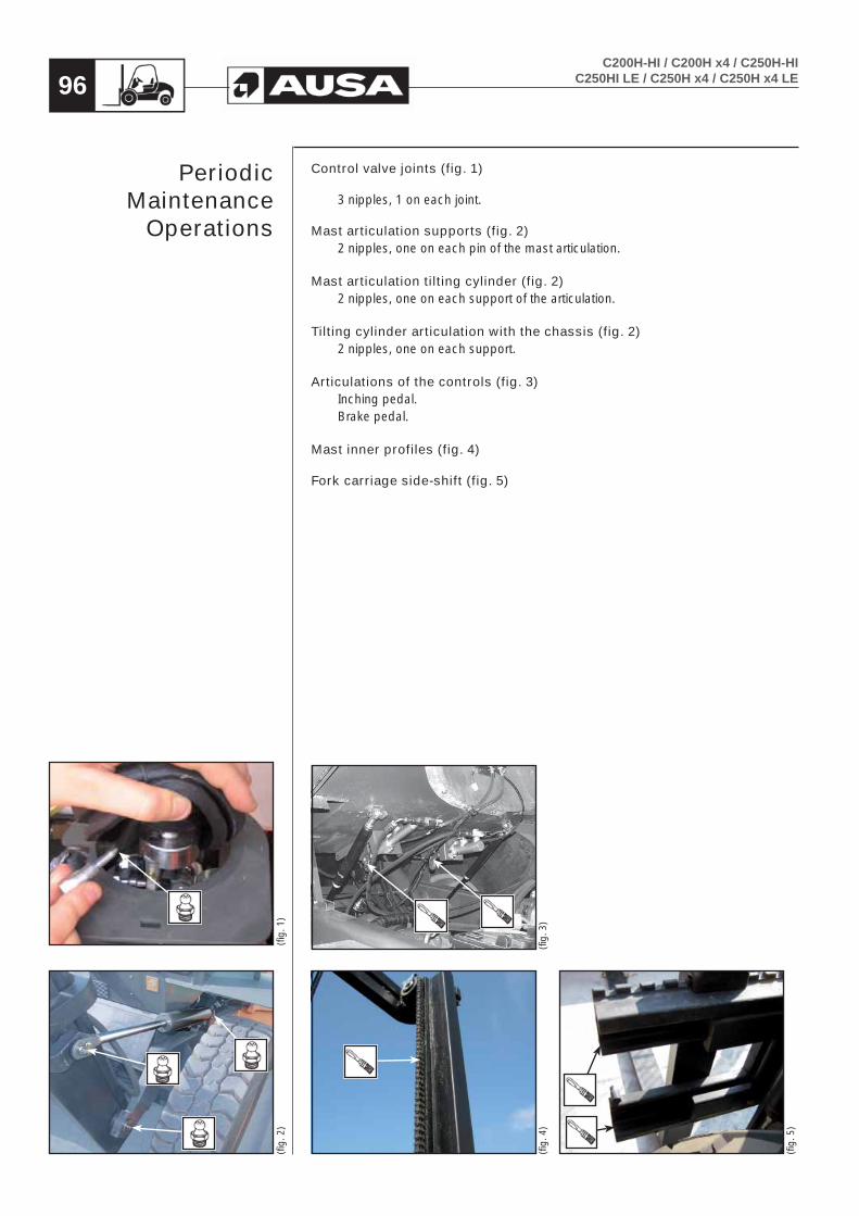
C200H-HI / C200H x4 / C250H-HIC250HI LE / C250H x4 / C250H x4 LE96
Control valve joints (fig. 1)
3 nipples, 1 on each joint.
Mast articulation supports (fig. 2)2 nipples, one on each pin of the mast articulation.
Mast articulation tilting cylinder (fig. 2)2 nipples, one on each support of the articulation.
Tilting cylinder articulation with the chassis (fig. 2)2 nipples, one on each support.
Articulations of the controls (fig. 3)Inching pedal.Brake pedal.
Mast inner profiles (fig. 4)
Fork carriage side-shift (fig. 5)
(fig.
1)
(fig.
2)
(fig.
3)
(fig.
4)
(fig.
5)
Periodic Maintenance
Operations

C200H-HI / C200H x4 / C250H-HIC250HI LE / C250H x4 / C250H x4 LE 97
Lighting and signaling system ()Indicator, parking, reverse, left and right side light bulbs: replacing (fig. 1).
- Undo bolts (a) and remove the lens.
- Remove the bulb by pressing it gently inwards and turning it to the left at the same time in order to release it from the lamp holder.
- Replace the bulb with a new bulb of the same type and power.
Operating beacon bulbs: replacing (fig. 2).
- Undo bolts (b) and remove the rear housing of the operating beacon.
Operating beacon bulb:
- Remove the connector from the bulb.
- Undo the clip fastening the bulb by pressing it inwards and to the right at the same time.
- Replace the bulb with a new bulb of the same type and power.
CAUTIONDo not touch the surface of the glass of the bulb. If it is dirty wipe gently using a clean dry cloth.
- Secure the clip again by pressing it inwards and to the left at the same time.
Indicator bulb:
- Remove the connector from the bulb.
- Remove the bulb by pressing it gently inwards and turning it to the left at the same time in order to release it from the lamp holder.
- Replace the bulb with a new bulb of the same type and power.
(fig.
1)
a
a
(fig.
2)
b
Periodic Maintenance
Operations

C200H-HI / C200H x4 / C250H-HIC250HI LE / C250H x4 / C250H x4 LE98
Rotating beacon bulb: replacing (fig. 1, 2)
- Turn the amber cover (a) of the rotary beacon to the left and remove.
- Unhook the plate (b) holding the bulb by pressing it inwards and to the left at the same time.
- Replace the bulb with a new bulb of the same type and power.
CAUTIONDo not touch the surface of the glass of the bulb. If it is dirty wipe gently using a clean dry cloth.
- Fasten the plate holding the bulb by pressing it inwards and to the right at the same time.
Electrical systemSteering column fuses: checking (fig. 3)
- Switch off the ignition.
- Remove the protective cover from the fuses by pulling it outwards.
- The burnt fuse can be recognised as the metal strip which is visible in the centre of each fuse will have melted (viewing window).
- Remove the burnt fuse and replace with a new fuse of the same type.
CAUTION
Do not use fuses of a higher value, this could cause major damage.
Battery fuses: checking (fig. 4)
- Switch off the ignition.
- Remove the protective cover from the fuses (c).
- The burnt fuse can be recognised as the metal strip which is visible in the centre of each fuse will have melted (viewing window).
- Remove the burnt fuse and replace with a new fuse of the same type.
CAUTION
Do not use fuses of a higher value, this could cause major damage.
(fig.
4)
(fig.
3)
(fig.
2)
(fig.
1)
a
b
c
Periodic Maintenance
Operations

C200H-HI / C200H x4 / C250H-HIC250HI LE / C250H x4 / C250H x4 LE 99
Windscreen wiper blade (): replacing (fig. 1)
- Loosen screws (a) to remove the blade from the windscreen wiper arm.
- Replace blade.
- Check that the screws (a) hold the blade tightly to the wiper arm.(fi
g. 1
)
a
Periodic Maintenance
Operations

C200H-HI / C200H x4 / C250H-HIC250HI LE / C250H x4 / C250H x4 LE100
Hydrostatic TransmissionError conditions The error conditions for this system will cover all important parts of the Automotive System. If any of the errors listed in the table occur, the machine will ramp down the pump current to stop and depending on the detected error, stays in STOP or changes to LIMITED-Mode. This mode will disable all control functions, like Constant-Speed for example, and will force the Motor to max. Displacement.If several errors appear at once, the errors are prioritized and the error with the lowest Error Flash Code will be shown
Table of Errors and System Reactions
Error Flash Code
Description Action Reference Page
11 Watchdog and Injection Channel SAFE-Mode Watchdog Control15 Watchdog SAFE-Mode
15
The Battery Voltage will be monitored. <9 V or > 36V is SAFE MODE12V System: < 9V is SAFE >16V is LIMITED MODE24V System: < 18V or > 32V is LIMITED MODE
SAFE-ModeSoftware
16Sensor Voltage Error. Nominal 5V. <4,875V or >5,125V is out of Range.
SAFE-Mode
21 Pump Current Forward Error LIMITED-Mode
Mechanical22 Pump Current Reverse Error LIMITED-Mode
21 and 22 Pump Current Forward and Reverse Error SAFE-Mode
25 COR Error SAFE-Mode
26 Buzzer/Brake Error LIMITED-Mode Electrical Outputs
28 Motor Current Error LIMITED-ModeInput/Output
Overview
30 Brake Pressure Defeat Error LIMITED-ModeMotor Brake
Pressure Defeat (BPD)
31 Engine Speed RPM Error LIMITED-Mode Software
35 FNR Shortcut Error SAFE-ModeElectrical Inputs /
Outputs
39 Inching Sensor Error LIMITED-ModePedal Data
43 Driving Sensor Error LIMITED-Mode
47 Mode Switch-B Error LIMITED-ModeElectrical Inputs /
Outputs
51 Swashplate Angle LIMITED-ModeSwashplate
Control
58 Motor RPM Error LIMITED-Mode Electrical Inputs / Outputs59 Motor Direction Error LIMITED-Mode
70 CAN Hardware Error LIMITED-Mode Log Functions – CAN Screens72 CAN RX Message timeout LIMITED-Mode
98 CAN Engine Remote Control SAFE-Mode J1939 CAN RX
General Status Information: Electrical Inputs Electrical Outputs
HydrostaticTransmission
Error conditions

C200H-HI / C200H x4 / C250H-HIC250HI LE / C250H x4 / C250H x4 LE 101
SAFE-ModeThe machine will stop with error ramp and will not be able to be driven.
• Clear the error• Restart the machine
LIMITED-ModeThe machine will stop with error ramp. If the error can not be cleared, the machine can run in LIMITED-Mode. The pump current will be reduced by parameter defined in the System Setup and the motor will be held in vgmax. Functions like swash-plate control, constant speed, flow limiter and speed limiter are switched off!
• Engine speed must be lower than the X1 value in the active mode
To reset the Error and run again with full functionality:
• Clear the error
The Error Flash Codes on the red led are interpreted as follows:
Code numbers interpretationThe LED lights for a short space of time is interpreted as “POINT” If time is longer interpreted as “LINE”
Introduction Space Tens Space Units
This example shows the error 35: Short circuit selector switch forward / neutral / reverse. The machine would go to safe mode
Additional Information
Sensor calibration Driving, Rocker and Inching
• If the minimum value will be lower than 2,5% of the sensor power (approximately 0,125V) an open circuit will be detected.
• If the maximum value will be higher than 97,5% of the sensor power (approximately 4,875V) a short circuit will be detected.
The error conditions for this system will cover all important parts of the MC024-21 Automotive System. If any of the errors listed in the table occur the machine will ramp down the pump current to stop.
HydrostaticTransmission
Error conditions

102C200H-HI / C200H x4 / C250H-HI
C250HI LE / C250H x4 / C250H x4 LE
Electric circuit
CABLE COLOURS
A Light Blue
B White
C Orange
G Yellow
H Grey
L Blue
M Brown
N Black
R Red
S Pink
V Green
Z Violet
Remark: In the bicolor cables, the longitudinal or traverse shape of the marks on the protective coating are to indicate the color. For example:
G - V: Yellow and Green with traverse marks G / V : Yellow / Green with longitudinal marks

103C200H-HI / C200H x4 / C250H-HIC250HI LE / C250H x4 / C250H x4 LE
Electric circuit 1 C200H / C200HI / C200H x4 / C250HI LE / C250H x4 LE

104C200H-HI / C200H x4 / C250H-HI
C250HI LE / C250H x4 / C250H x4 LE
Electric circuit 2 C200H / C200HI / C200H x4 / C250HI LE / C250H x4 LE

105C200H-HI / C200H x4 / C250H-HIC250HI LE / C250H x4 / C250H x4 LE
Electric circuit 3 C200H / C200HI / C200H x4 / C250HI LE / C250H x4 LE

106C200H-HI / C200H x4 / C250H-HI
C250HI LE / C250H x4 / C250H x4 LE
Electric circuit 4 C200H / C200HI / C200H x4 / C250HI LE / C250H x4 LE

107C200H-HI / C200H x4 / C250H-HIC250HI LE / C250H x4 / C250H x4 LE
Electric wiring C200H / C200HI / C200H x4 / C250HI LE / C250H x4 LE
Item Description Sheet Item Description Sheet
A28 Pre-heat relay 1 M15 Rear wiper motor 4
A39 Horn 2 M20 Electric fuel pump 3
C2 Condenser 4 M25 Starter motor 1
E12 Left hand headlight 4 M32 Windscreen washer motor 3
E13 Right hand headlight 4 P52 Instrument panel 1
F1 Low beam fuse (10A) 4 R21 Pre-heater plugs 1
F2 High Beam fuse (10A) 4 S16 Air filter blockage indicator 1
F3 Side lights / brake lights / reverse relay fuse (7’5A) 4 S18 Hydraulic oil level sensor 1
F4 Front windscreen wiper fuse (15A) 3 S23 Coolant temperature warning switch 1
F5 Ignition feed stop solenoid / fuel pump / pre-heating / alternator fuse (7’5A) 1 S24 Engine oil pressure switch 3
F6 Ignition feed warning lights / horn fuse (10A) 4 S33 Seat switch 3
F7 Seat switch / hand brake / timer relay fuse (7’5A) 2 S40 Brake lights switch 3
F8 3rd.and 4rth.service solenoids (sideshift or attachments) fuse (7’5A) 2 S51 Ignition barrel 1
F9 Dash panel lights / heater motor fuse (10A) 1 S53 Hazard light switch 4
F10 Flashing / rotating beacon and working lights fuse (25A) 4 S54 Indicator switch 4
F11 Permanent live warning lights switch (5A) 4 S55 Headlight / sidelight switch 4
FG1 Permanent live main fuse (50A) 1 S56 Rotating / Flashing beacon switch 4
FG2 Starter motor relay main fuse (50A) 1 S57 Worklight switch 4
FG3 Pre-heat relay main fuse (30A) 1 S58 Heater motor switch 3
FG4 Battery main fuse (200A) 1 S59 Optional switch 2
G19 Battery 1 S60 Front windscreen wiper switch 3
G26 Alternator 1 S61 Handbrake switch 2
H1 Right hand reverse light 4 S99 Joystick spool valve lock link connector 3
H2 Brake and tail lights right hand side 4 S100 Forward and Reverse switch (joystick) 2
H3 Rear right hand indicator 4 S101 Horn switch (joystick) 2
H5 Rear left hand indicator 4 S102 2 Speed selector switch (joystick) 2
H6 Brake and tail lights left hand side 4 S103 3rd. service switch (side shift) (joystick) 2
H7 Left hand reverse light 4 S104 4rd. service switch (attachments) (joystick) 2
H9 Number plate light 4 S31a Fuel tank gauge 3
H14 Work lights 4 S31b Low level fuel warning light 3
H17 Reverse alarm 3 Y22 Engine stop solenoid 1
H45 Rotating / Flashing beacon 4 Y29 Forward solenoid 2
H71 Dash panel buzzer (warning lights) 1 Y30 Reverse solenoid 2
K63 Driver’s seat timer relay 2 Y34 Parking brake solenoid 3
K64 Flasher relay 4 Y35 2 Speed solenoid (not used) 2
K65 Neutral start relay 1 Y36 Joystick spool valve lock units 3
K67 Reverse alarm relay (night silence) 2 Y37 3rd. service solenoid (side shift) 2
K68 Starter relay 1 Y38 4rd. service solenoid (attachments) 2
K73 FNR switch disconnection relay (handbrake on) 2 Y39 Brake assistance solenoid 3
M14 Windshild wiper 1

108C200H-HI / C200H x4 / C250H-HI
C250HI LE / C250H x4 / C250H x4 LE
Electric circuit 1C250H / C250HI / C250H x4

109C200H-HI / C200H x4 / C250H-HIC250HI LE / C250H x4 / C250H x4 LE
Electric circuit 2C250H / C250HI / C250H x4

110C200H-HI / C200H x4 / C250H-HI
C250HI LE / C250H x4 / C250H x4 LE
Electric circuit 3C250H / C250HI / C250H x4

111C200H-HI / C200H x4 / C250H-HIC250HI LE / C250H x4 / C250H x4 LE
Electric circuit 4C250H / C250HI / C250H x4
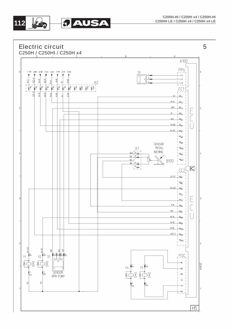
112C200H-HI / C200H x4 / C250H-HI
C250HI LE / C250H x4 / C250H x4 LE
Electric circuit 5C250H / C250HI / C250H x4

113C200H-HI / C200H x4 / C250H-HIC250HI LE / C250H x4 / C250H x4 LE
Electric wiring C250H / C250HI / C250H x4
Item Description Sheet Item Description Sheet
A100 Sauer Unit (ECU) 5 M15 Rear wiper motor 4
A28 Pre-heat relay 1 M20 Electric fuel pump 3
A39 Horn 2 M25 Starter motor 1
B100 Inching sensor 5 M32 Windscreen washer motor 3
C2 Condenser 4 P52 Instrument panel 1
E12 Left hand headlight 4 R21 Pre-heater plugs 1
E13 Right hand headlight 4 S1 RPM Motor 5
F1 Low beam fuse (10A) 4 S2 RPM Pump 5
F2 High Beam fuse (10A) 4 S16 Air filter blockage indicator 1
F3 Side lights / brake lights / reverse relay fuse (7’5A) 4 S18 Hydraulic oil level sensor 1
F4 Front windscreen wiper fuse (15A) 3 S23 Coolant temperature warning switch 1
F5 Ignition feed stop solenoid / fuel pump / pre-heating / alternator fuse (7’5A) 1 S24 Engine oil pressure switch 3
F6 Ignition feed warning lights / horn fuse (10A) 4 S33 Seat switch 3
F7 Seat switch / hand brake / timer relay fuse (7’5A) 2 S40 Brake lights switch 3
F8 3rd.and 4rth.service solenoids (sideshift or attachments) fuse (7’5A) 2 S51 Ignition barrel 1
F9 Dash panel lights / heater motor fuse (10A) 1 S53 Hazard light switch 4
F10 Flashing / rotating beacon and working lights fuse (25A) 4 S54 Indicator switch 4
F11 Permanent live warning lights switch (5A) 4 S55 Headlight / sidelight switch 4
FG1 Permanent live main fuse (50A) 1 S56 Rotating / Flashing beacon switch 4
FG2 Starter motor relay main fuse (50A) 1 S57 Worklight switch 4
FG3 Pre-heat relay main fuse (30A) 1 S58 Heater motor switch 3
FG4 Battery main fuse (200A) 1 S59 Optional switch 2
G19 Battery 1 S60 Front windscreen wiper switch 3
G26 Alternator 1 S61 Handbrake switch 2
H1 Right hand reverse light 4 S99 Joystick spool valve lock link connector 3
H2 Brake and tail lights right hand side 4 S100 Forward and Reverse switch (joystick) 2
H3 Rear right hand indicator 4 S101 Horn switch (joystick) 2
H5 Rear left hand indicator 4 S102 2 Speed selector switch (joystick) 2
H6 Brake and tail lights left hand side 4 S103 3rd. service switch (side shift) (joystick) 2
H7 Left hand reverse light 4 S104 4rd. service switch (attachments) (joystick) 2
H9 Number plate light 4 S31a Fuel tank gauge 3
H14 Work lights 4 S31b Low level fuel warning light 3
H17 Reverse alarm 3 Y1 Speed control solenoid 5
H45 Rotating / Flashing beacon 4 Y2 Braked pressure control solenoid 5
H71 Dash panel buzzer (warning lights) 1 Y4 Front solenoid 5
K63 Driver’s seat timer relay 2 Y5 Rear solenoid 5
K64 Flasher relay 4 Y22 Engine stop solenoid 1
K65 Neutral start relay 1 Y34 Parking brake solenoid 3
K67 Reverse alarm relay (night silence) 2 Y36 Joystick spool valve lock units 3
K68 Starter relay 1 Y37 3rd. service solenoid (side shift) 2
K73 FNR switch disconnection relay (handbrake on) 2 Y38 4rd. service solenoid (attachments) 2
K74 H1 inhibit relay 2 Y39 Brake assistance solenoid 3
M14 Windshild wiper 1 Y45 4x4 transmission solenoid 2

114C200H-HI / C200H x4 / C250H-HI
C250HI LE / C250H x4 / C250H x4 LE
Hydraulic diagram (Hydraulic appliances)

115C200H-HI / C200H x4 / C250H-HIC250HI LE / C250H x4 / C250H x4 LE
Hydraulic diagram (Transmission)C200H / C200HI / C200H x4 / C250HI LE / C250H x4 LE

116C200H-HI / C200H x4 / C250H-HI
C250HI LE / C250H x4 / C250H x4 LE
Hydraulic diagram (Transmission)C250H / C250HI / C250H x4

117C200H-HI / C200H x4 / C250H-HIC250HI LE / C250H x4 / C250H x4 LE
Transmission Troubleshooting
INSTRUCTIONS FOR THE IDENTIFICATION OF FAILURES IN HYDROSTATIC TRANSMISSIONS
FAILURES POSSIBLE CAUSE CHECK LOCATION CORRECT VALUES
The machine does not move neither forward nor reserve
Oil Level is low Oil level Oil tank
Suction hose is bent or squashed Suction hose
Hydraulic oil cartridge is clogged Depressor marked in vacuum gauge Suction filter < 0,3 bar
Faulty coupling Motor or pump coupling
Pre-load pump turns counter wise to engine
Load pressurePressure intake with a gauge on pump sport M3 (SAUER GROUP) or S (BOSCH REXROTH GROUP)
20 ÷ 24 barFaulty pre-load pump
Faulty oil motor
Directional solenoid does not workResistance and voltage Control box (SAUER)
Directional solenoids in pump
Inching is seized, disconnected or badly set (SAUER)
Throw and connections Pedal and electric connections
Faulty oil strainerFaulty oil suction Seadling of tubes connectors and suction
Oil connections
Non instant motion response, abnormal
Oil is air emulsified or Oil level is lowOil level seating of pipes / hoses, fittings
Oil tank, fittings
Vacuum filter is clogged Depressor marked in vacuum gauge Vacuum filter < 0,3 bar
Inching is seized, disco meeted or badly connected (SAUER)
Potentiometer, linkage and connections
Pedal and electric connections
Engine is overloaded
Low engine power or faulty engineEngine does not accelerate at max. Load
Engine85 ÷ 95 % max rpm. of engine
High pressure limit is set too low Working pressure Working pressure ports in pumpRecommended max. Pressure 345 or 410 bar.
Inching is seized (SAUER) Potentiometer / linkage Pedal < 0,3 bar
Low traction power
Engine does not work at nominal level or it’s over Haul of accelerator lever Engine85 ÷ 95 % max rpm. of engine
Low load pressure Load pressurePressure intake with a gauge on pump sport M3 (SAUER GROUP) or S (BOSCH REXROTH GROUP)
20 ÷ 24 bar.
Inching is seized (SAUER)Potentiometer / linkage Pedal
M4, M5 (SAUER) or Xa, Xb (BOSCH REXROTH) Piloting hoses of hydrostatic motor are reversed.
Hydraulic chart Connections
Hydraulic Oil overheating Dirt in radiator Radiator oil
Hydraulic oil overheating
Low oil level Oil level
Oil tankFaulty oil Oil degradation an pollution
Suction line is not sealed Sealing for hoses, fittings and cartridge
Oil connections
Faulty high pressure relief valves Working pressure Working pressure ports in pumpRecommended max. Pressures 345 or 410 bar.
Radiator is dogged Dirt in radiator
Transmission over speed
Max. Engine RPM is higher than recommended Max. RPM on the engine Engine
Faulty hydrostatic motor. Does not move to max. flow.
Irregular running
M4, M5 (SAUER) or Xa, Xb (BOSCH REXROTH) Piloting hoses of hydrostatic motor are reversed.
Hydraulic Chart Oil connections
Insufficient acceleration
Low engine power Haul of accelerator lever Engine
M4, M5 (SAUER) or Xa, Xb (BOSCH REXROTH) Piloting hoses of hydrostatic motor are reversed.
Hydraulic Chart Oil connections
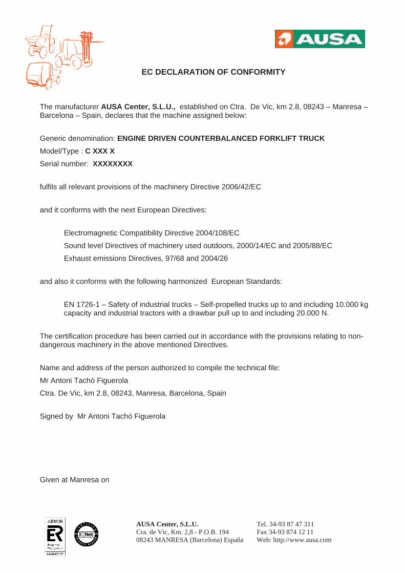
AUSA Center, S.L.U. Tel. 34-93 87 47 311 Cra. de Vic, Km. 2,8 - P.O.B. 194 Fax 34-93 874 12 11 08243 MANRESA (Barcelona) España Web: http://www.ausa.com
EC DECLARATION OF CONFORMITY
The manufacturer AUSA Center, S.L.U., established on Ctra. De Vic, km 2.8, 08243 – Manresa – Barcelona – Spain, declares that the machine assigned below:
Generic denomination: ENGINE DRIVEN COUNTERBALANCED FORKLIFT TRUCKModel/Type : C XXX X Serial number: XXXXXXXX
fulfils all relevant provisions of the machinery Directive 2006/42/EC
and it conforms with the next European Directives:
Electromagnetic Compatibility Directive 2004/108/EC
Sound level Directives of machinery used outdoors, 2000/14/EC and 2005/88/EC
Exhaust emissions Directives, 97/68 and 2004/26
and also it conforms with the following harmonized European Standards:
EN 1726-1 – Safety of industrial trucks – Self-propelled trucks up to and including 10.000 kg capacity and industrial tractors with a drawbar pull up to and including 20.000 N.
The certification procedure has been carried out in accordance with the provisions relating to non-dangerous machinery in the above mentioned Directives.
Name and address of the person authorized to compile the technical file:
Mr Antoni Tachó Figuerola
Ctra. De Vic, km 2.8, 08243, Manresa, Barcelona, Spain
Signed by Mr Antoni Tachó Figuerola
Given at Manresa on


![THE STRUCTURE OF AERIAL DISPLAYS IN THREE SPECIES OF ... · April 1983] Calidris Aerial Displays 443 a A B C b B C 500 H ) J 250 5OO G 250 250 • Fig. 3. Oscillograms of Rhythmically](https://img.dokumen.tips/doc/110x75/5fb160b40afdad3d725d3eb6/the-structure-of-aerial-displays-in-three-species-of-april-1983-calidris-aerial.jpg)


