Embed Size (px)
DESCRIPTION
Extended Uart The High Speed Digital Systems Laboratory, Electrical Engineering Faculty, Technion. By: Marganit Fina Supervisor: Rivkin Ina Winter 2007/8 Duration: Semester. Final Presentation. Project purpose. - PowerPoint PPT Presentation
Citation preview
Extended Uart The High Speed Digital Systems Laboratory,
Electrical Engineering Faculty, Technion
By: Marganit Fina
Supervisor: Rivkin Ina
Winter 2007/8
Duration: Semester
Final Presentation

Project purpose
Extending the UART IP Core from previous project ,to UART 16550 and adding additional features.
Goal : – Write a UART Core in VHDL, that can be used in other
projects– Synthesize the UART-Core for FPGA.– Two phases core-verification:
RTL logic verification ( VHDL-based test-benches) Lab – real-time testing of the core

UART work environment
PC
FPGA
RS-232communication
UARTCore
User
The UART passes bidirectional data from the PC to the User .
The USER uses the “services” of the UART to receive and send data from/to the PC.
Introduction : UART - Universal Asynchronous Receiver-Transmitter
Converts the bytes it receives from the computer along parallel circuits into a single serial bit stream for outbound transmission .
On inbound transmission, converts the serial bit stream into the bytes that the computer handles.
Adds a parity bit on outbound transmissions and checks the parity of incoming bytes and discards the parity bit (optional).
Adds start and stop delineators on outbound and strips them from inbound transmissions .
UART’s Features
Support sending and receiving data-packets in length of 5-8 bits.
– The UART has a new control interface ,which enable the client to determine the amount of bits (in a signal transaction).
Preamble data-assertion : the UART can add/remove standard asynchronous communication bits( start, stop and parity) for each received data-packet in the host-side.
– For all packet-lengths
UART’s Features - continue
Support even, odd and no-parity bit generation and detection.– Additional control interface to support parity
detection and generation, while sending the data in RS232.
Support sending 1,2 stop-bit.– The RS232 serial interface supports 1 or 2 stop
bits to signal the PC end of transaction.– The amount of stop bits is determined by the host.
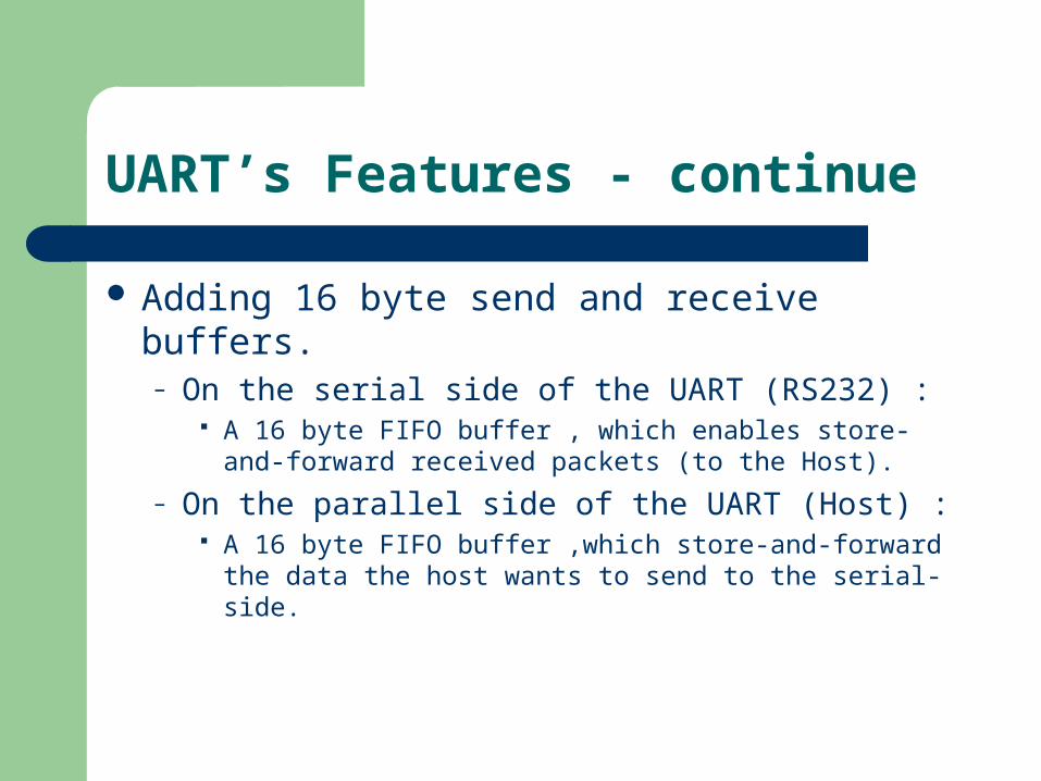
UART’s Features - continue
Adding 16 byte send and receive buffers.– On the serial side of the UART (RS232) :
A 16 byte FIFO buffer , which enables store-and-forward received packets (to the Host).
– On the parallel side of the UART (Host) : A 16 byte FIFO buffer ,which store-and-forward the data
the host wants to send to the serial-side.
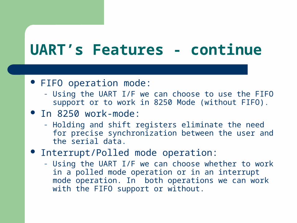
UART’s Features - continue
FIFO operation mode:– Using the UART I/F we can choose to use the FIFO support
or to work in 8250 Mode (without FIFO). In 8250 work-mode:
– Holding and shift registers eliminate the need for precise synchronization between the user and the serial data.
Interrupt/Polled mode operation:– Using the UART I/F we can choose whether to work in a
polled mode operation or in an interrupt mode operation. In both operations we can work with the FIFO support or without.

UART’s Features - continue
Programmable baud generator divides any input clock by to and generates the 16xClock.
Support baud rate from 2400 up-to 115200. Packet Checker logic
– When a new packet is collected. It detects parity error ,frame error or overrun error ,and reports it to the user on the Host side.
1 162 1

UART’s data-path example : User -> RS-232
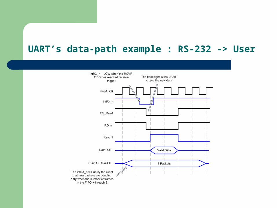
UART’s data-path example : RS-232 -> User
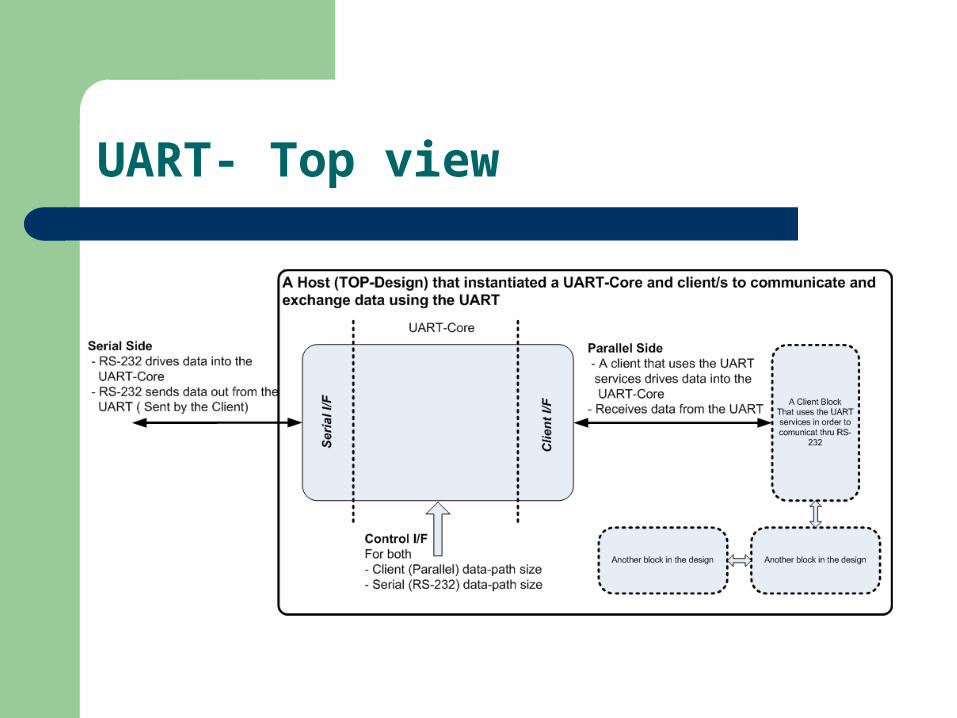
UART- Top view
UART Port-Map: User’s Interface side
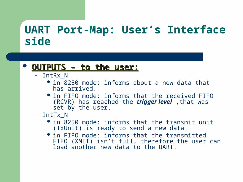
OUTPUTS – to the user:OUTPUTS – to the user:– IntRx_N
in 8250 mode: informs about a new data that has arrived. in FIFO mode: informs that the received FIFO (RCVR) has
reached the trigger level ,that was set by the user.– IntTx_N
in 8250 mode: informs that the transmit unit (TxUnit) is ready to send a new data.
in FIFO mode: informs that the transmitted FIFO (XMIT) isn’t full, therefore the user can load another new data to the UART.

UART Port-Map: User’s Interface side
OUTPUTS – to the user :OUTPUTS – to the user :– Ferr_N
indicates about a frame error (interrupt mode only).– Oerr_N
Indicates about an overrun error (interrupt mode only).– Paerr
indicates about a parity error (interrupt mode only).– SysClk
the transmit unit clock.– DataOut
from here we get the new 8,7,6 or 5 -bit data (parallel form).

UART Port-Map: User’s Interface side
OUTPUTS – to the user :OUTPUTS – to the user :– Empty_xmit
indicates that the UART has sent all the data that was given to him by the user (FIFO and interrupt mode only).
– RCVR_empty indicates that there is no new data for the user to read. (FIFO and
interrupt mode only).

UART Port-Map: User’s Interface side
OUTPUTS – to the user :OUTPUTS – to the user :– Status [7:0]
operates in polled mode in both 8250 and FIFO operations .gives information about the status of the UART:
– Full/Emptiness of the FIFO’s , Transmit and Receive Units.– Overrun error.– Parity error .– Frame error.

UART Port-Map: User’s Interface side
INPUTS to the UART:INPUTS to the UART:– FPGA_Clk
• FPGA base clock.
– Divider • Determining the Baud Rate.
– Reset• Active-low
– Mode• Determining whether use fifo support or not.
– Int_enable• Determining interrupt or polled mode operation.
– CS_Write• Loading a new data to the UART for transmitting.
UART Port-Map: User’s Interface side
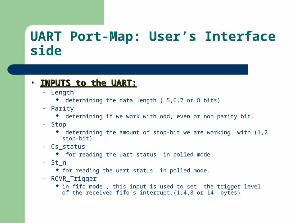
• INPUTS to the UART:INPUTS to the UART:– Length
determining the data length ( 5,6,7 or 8 bits)– Parity
determining if we work with odd, even or non parity bit.– Stop
determining the amount of stop-bit we are working with (1,2 stop-bit).– Cs_status
for reading the uart status in polled mode.– St_n
for reading the uart status in polled mode.– RCVR_Trigger
in fifo mode , this input is used to set the trigger level of the received fifo’s interrupt.(1,4,8 or 14 bytes)
UART I/F : The Host’s side I/F
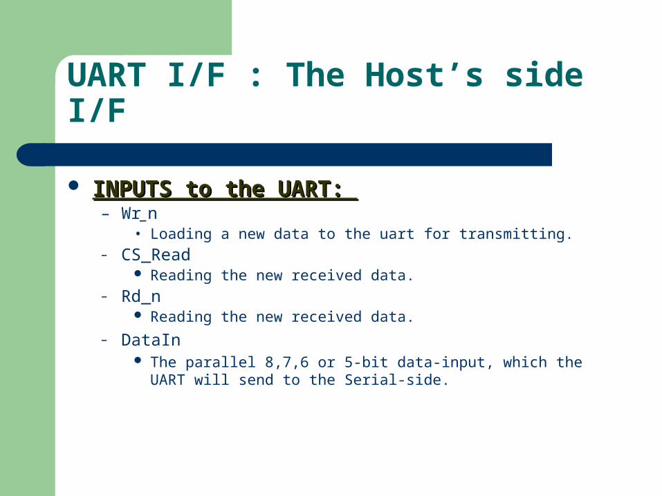
INPUTS to the UART: INPUTS to the UART: – Wr_n
• Loading a new data to the uart for transmitting.– CS_Read
Reading the new received data.– Rd_n
Reading the new received data.
– DataIn The parallel 8,7,6 or 5-bit data-input, which the UART will send to the
Serial-side.
UART Port-Map: RS-232 I/F
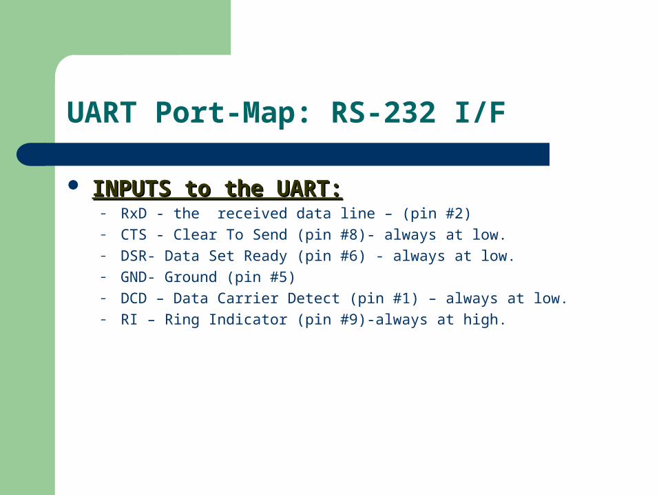
INPUTS to the UART:INPUTS to the UART:– RxD - the received data line – (pin #2) – CTS - Clear To Send (pin #8)- always at low.– DSR- Data Set Ready (pin #6) - always at low.– GND- Ground (pin #5)– DCD – Data Carrier Detect (pin #1) – always at low.– RI – Ring Indicator (pin #9)-always at high.
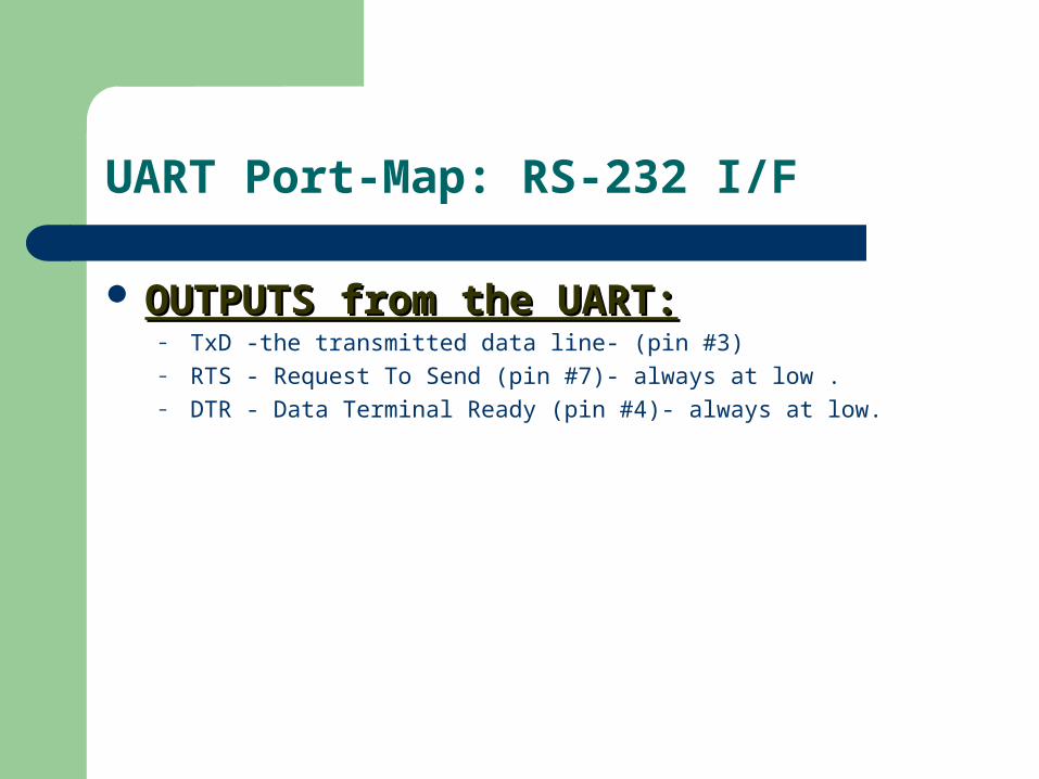
UART Port-Map: RS-232 I/F
OUTPUTS from the UART:OUTPUTS from the UART:– TxD -the transmitted data line- (pin #3)– RTS - Request To Send (pin #7)- always at low .– DTR - Data Terminal Ready (pin #4)- always at low.
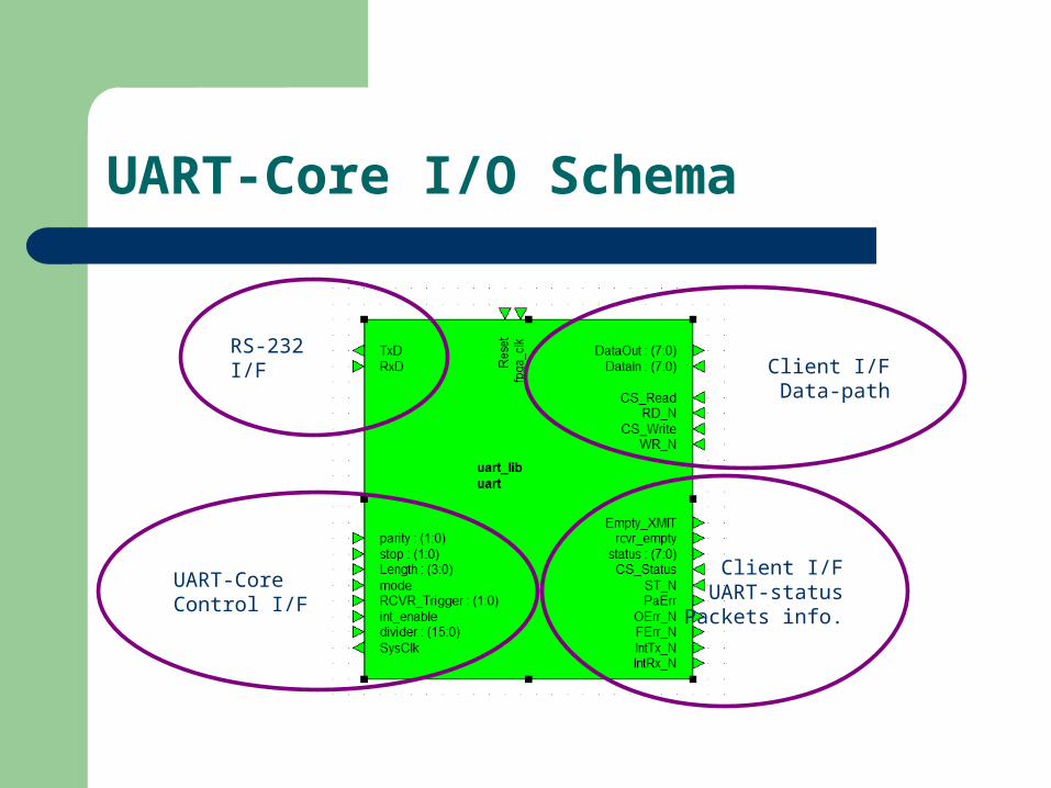
UART-Core I/O Schema
RS-232 I/F
UART-CoreControl I/F
Client I/F Data-path
Client I/FUART-statusPackets info.
UART Structure
The UART is divided into two main
sub-blocks:– Miniuart Unit : controls sending and receiving
processes.– Clock-control Units : responsible for creating the
clocks for the miniuart block, according to the host’s requested Baud-Rate.

UART Structure

Clock Control Unit
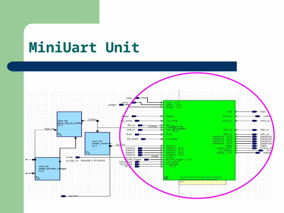
MiniUart Unit
MiniUart Structure
Consists of 6 main blocks:– 2 eb1– RCVR FIFO– RX Unit – TX Unit– XMIT FIFO – RSBusCtrl
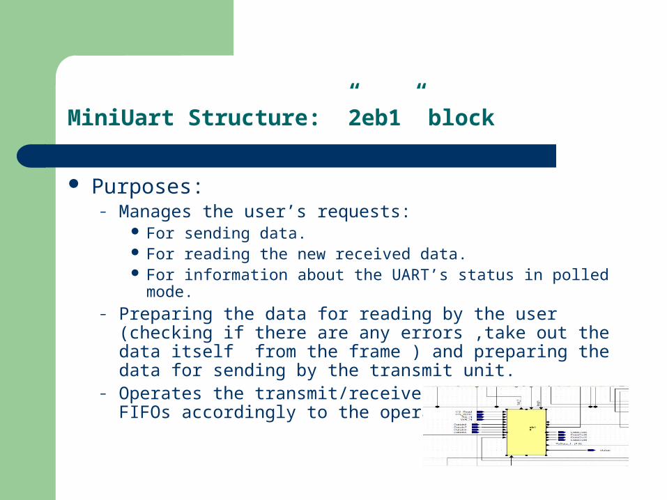
MiniUart Structure: ”2eb1” block
Purposes:– Manages the user’s requests:
For sending data. For reading the new received data. For information about the UART’s status in polled mode.
– Preparing the data for reading by the user (checking if there are any errors ,take out the data itself from the frame ) and preparing the data for sending by the transmit unit.
– Operates the transmit/receive units and the FIFOs accordingly to the operation mode.

MiniUart Structure: The Receive FIFO (RCVR)
Consists of 3 blocks:– RCVR Controller.– RCVR Operator.– DUAL Port 16x10Bits RAM.

The Receive FIFO (RCVR): RCVR Controller block.
Purposes: – Calculates the write address and the read address,– Informs about the num of occupied slots, – Full and empty
indications
– Overflow and
underflow indications of the FIFO.

The receive FIFO (RCVR): RCVR Operator block.
Purposes: – manages the RCVR controller and the DUAL port
RAM according to the state of the receive unit and user’s requests.
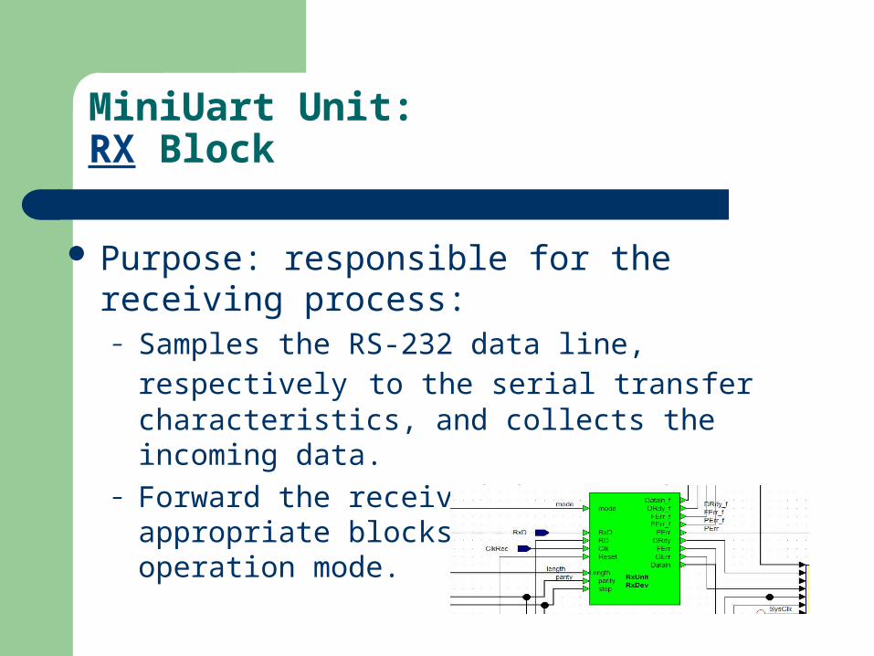
MiniUart Unit:RX Block
Purpose: responsible for the receiving process:– Samples the RS-232 data line, respectively to the
serial transfer characteristics, and collects the incoming data.
– Forward the received data to the appropriate blocks, according to the operation mode.

MiniUart Unit:TX Block
Purpose: responsible for the transmitting process :– Converts and Sends the data vector to the RS-232
data line ,respectively to the serial transfer characteristics.
MiniUart Structure:the Transmitting FIFO (XMIT)
Consists of 3 blocks:– XMIT Controller.– XMIT Operator.– DUAL Port RAM.

The Transmitting FIFO (XMIT):XMIT Cotroller
Purpose :– Calculates the write address and the read
address,– Informs about the num of occupied slots, – Full and empty indications– Overflow and underflow indications of the FIFO.

The Transmitting FIFO (XMIT):XMIT Operator
Purpose : – Manages the XMIT Controller and the Dual Port
RAM , according the state of the transmitting unit and user’s requests.
MiniUart Unit:RSbusCtrl block
This block has 4 different mode of functioning, match for every operation mode of the UART: – polled/interrupt. – with FIFO support/without FIFO support.
This block is responsible for sending interrupts, based on the UART’s status and the user’s preferences.

MiniUart Unit:RSbusCtrl block
This block also informs about parity error, frame error ,overrun error and emptiness of the XMIT and RCVR FIFOs.
The outputs of this block combine the status vector, which active in polled mode.

UART - Core : Verification
An “error generator” block was build. Purpose:
– Inverse bits in the new received data, enable checking the UART’s behavior to parity and frame errors.

UART - Core : Verification
Sending files to the UART, using HyperTerminal and got back the correct frames that were received by the UART, number of frame errors and number of parity errors, that were generated by the “error generation”.
This was tested in all the 4 operation modes of the UART (with FIFO support/without FIFO support , interrupt /polled mode).
This was tested in all the baud rates from 2400 to 115200.

UART - Core : Verification
Verified/Tested corner-cases :– Correct roll-over of both of the FIFOs.– Using different RCVR Trigger of the RCVR FIFO.– Changing serial transfer characteristics during
running.– Correct overrun error in different operations
modes.
UART - Core : Verification
Verified/Tested corner-cases : – UART’s support of various serial transfer
characteristics :– 5,6,7 and 8-bit characters. – Even, odd or none parity.– 1,2 stop bit.
Further improvements
16850 UART- which includes a 128 bytes FIFO.
DUART- (“Dual UART”) :combines two UARTs into
a single chip . USART-(A Universal Synchronous Asynchronous
Receiver /Transmitter) : a UART that can also communicate synchronously.


