Embed Size (px)
Citation preview

THE NATURE OF THE WINGTIP VORTEX FLOW
by J. Claude Patterson, Jr.
The wingtip vortex, the strength of which is a function of the lift or weight of an aircraft having a particular wing aspect ratio, has been in existence since the beginning of flight. It has been an ever-increasing problem as the weight of each succeeding generation of aircraft has in-creased. In addition to the large drag associated with the lift-induced vortex, 35 to 40 percent of the total drag of a transport type airplane, the vortex system of the large jumbo-jet aircraft of to-day has become a major problem to the air traffic controller in the terminal area as well as an un-seen hazard to smaller aircraft during cruise flight. This is a result of not only the strength of the vortex but also the persistent nature of its flow. To fully comprehend the nature of lift-induced wingtip vortex, the lift produced by a wing of an airplane should be closely examined.
Air is actually a mixture of a number of gases, approximately 75 percent nitrogen, 16 percent oxygen, with the remaining 9 percent made up mainly of argon along with minute amounts of helium, neon, carbon dioxide, kayton and methane. The molecules of the different gases are able to move freely amongst each other because there is no chemical bond or magnetic attraction between the different atoms of this mixture, which would tend to hold them together or hinder their movement. The molecules of each gas in the air are pushed forward, up, down, sideways and left mostly spinning around in all directions after an aircraft has rushed through this mixture of gases. To simulate this free movement of air, each atom of each gas could be compared to a grain of sand, where ocean waves have worn away all the sharp edges. If an at-tempt is made to pick up this sand, the grains will slip through your fingers, flowing back to the ground. But sand can, however, be scooped up in the palm of your hand, which actually com-presses the grains together. Sand can be compressed, offering resistance, but when pulled the grains just slip by one another having no ability to hold to each other. These same characteristics are found in air where the atoms can be pushed together and will push back, but cannot be pulled and will not pull back.
When air suction is mentioned, a push is actually implied rather than a pull. There are a number of examples showing that air cannot be pulled, only pushed. If, for example, a glass tube 36 inches in length with an inside diameter of 1/8 of an inch, is permanently sealed at one end, filled with mercury and inverted such that the opened end, sealed temporarily, is submerged into a reservoir of mercury, part of the fluid will run into the reservoir when the open end is unsealed. The height of the mercury in the tube, measured from the reservoir surface, will be 29.9 inches on a standard day. The pressure of the air in the tube above the mercury, approximately six inches, will be zero pounds per square inch. One might wonder, is the air at zero pressure hold-ing the mercury up in the glass tube or is it the atmospheric pressure pushing down on the mer-cury in the reservoir? It can be shown that the latter is the case. Obviously a barometer has just been described which has the sole purpose of weighing the atmosphere.
1
We could not drink soda through a straw if it were not for atmospheric pressure. The fa-miliar home vacuum cleaner machine, where a high speed motor/fan blade combination blows air out one end of a tube and allows the atmospheric pressure to push the dirty air into the other end, would not function were it not for atmospheric pressure. Even our breathing is the result of atmospheric pressure forcing air into our expanded lungs. We are at the bottom of an ocean of air where the atmospheric pressure is the result of a column of air twenty-eight miles high exert-ing a pressure of approximately two thousand one hundred twenty (2,120) pounds on every square foot of the earth. The coffee table in your living room is supporting approximately eight tons of air but fortunately there are also eight tons of air pushing upward from below the table, equalizing the force felt by the table. If it were possible to increase the pressure on the lower side of the table, dynamically, it would rise from the floor like the proverbial barn door which is known to be able to fly if there' is enough power to move the door through the air at great enough speed. It might be mentioned here that the potential energy of air is directly related to its pressure, the higher the pressure the higher its potential energy and conversely the lower the pressure the lower the potential energy. Zero pressure has zero potential.
To produce lift, the lower surface of a wing therefore pushes the mass of air beneath it vertically downward. A force is created in that direction (force equals mass times acceleration). The wing pushes the air downward and the air reacts to this action, Newton's third law, by push-ing back against the lower surface of the wing in an upward direction creating a reaction force, which is lift.
The mass of air below a wing in motion, affected by the wing’s lower surface, also in-cludes part of the air that would have been in the area above the wing but is blocked by the wing itself. This additional air mass, also accelerated downward by the wing’s lower surface, in-creases the force developed by the wing while leaving the air above the wing less dense and therefore less able to resist the lift force developed. The higher-pressure ambient air surrounding the wing will rush in from all directions in an attempt to remedy this deficiency above the wing.
The wing produces more lift than indicated by the simple equation of dynamic pressure times the area effected (F=qA). I will endeavor to explain this phenomenon, as well as the aforementioned increase in mass. First there are a couple of misconceptions that might be men-tioned which would be helpful if clarified. Aeronautics is taught using the wind tunnel where air is forced to flow past a stationary model of an aircraft. The wind tunnel is an excellent tool for aeronautical research if used properly and possibly every airplane that has ever flown was first tested in a wind tunnel. But as a result of this training early in the research engineer's career, there is a mistaken consensus that air also streams by an airplane in flight. It is very difficult, at first, to think otherwise. In reality the airplane is charging through air, which is made up of mil-lions of practically stationary molecules of the different gases that comprise it and which are pre-sent everywhere. The airplane is actually planing on the air as its name implies. It pushes air forward and downward as it moves through the air, forming an invisible wave of air particles on which it rides. It is planing on air similar to a boat planing on water. It is easier to see a boat
2
planing because it is continually moving through two different mediums: both water and air, one visible and one invisible.
In flight the wing’s lower surface is charging against the air, causing an obverse compres-sion beneath the wing. The upper surface pressure, on the other hand, is reduced not only due to the air captured or blocked by the wing’s lower surface, but also due to the fact that this surface is moving away from the air. This low pressure leads to a favorable pressure gradient over the forward half of the airfoil section, leading to an acceleration of the flow by the ambient pres-sures, where the velocity may exceed the stream velocity over this area. This is followed by an unfavorable pressure gradient over the aft half the airfoil section, where the air flow must return to ambient conditions. The upper surface curvature is important and has been studied and tested for many years to perfect a shape which will provide a flow without separation. The lower wing surface, which is actually the lift-producing surface, has been almost ignored—a situation that will hopefully be remedied.
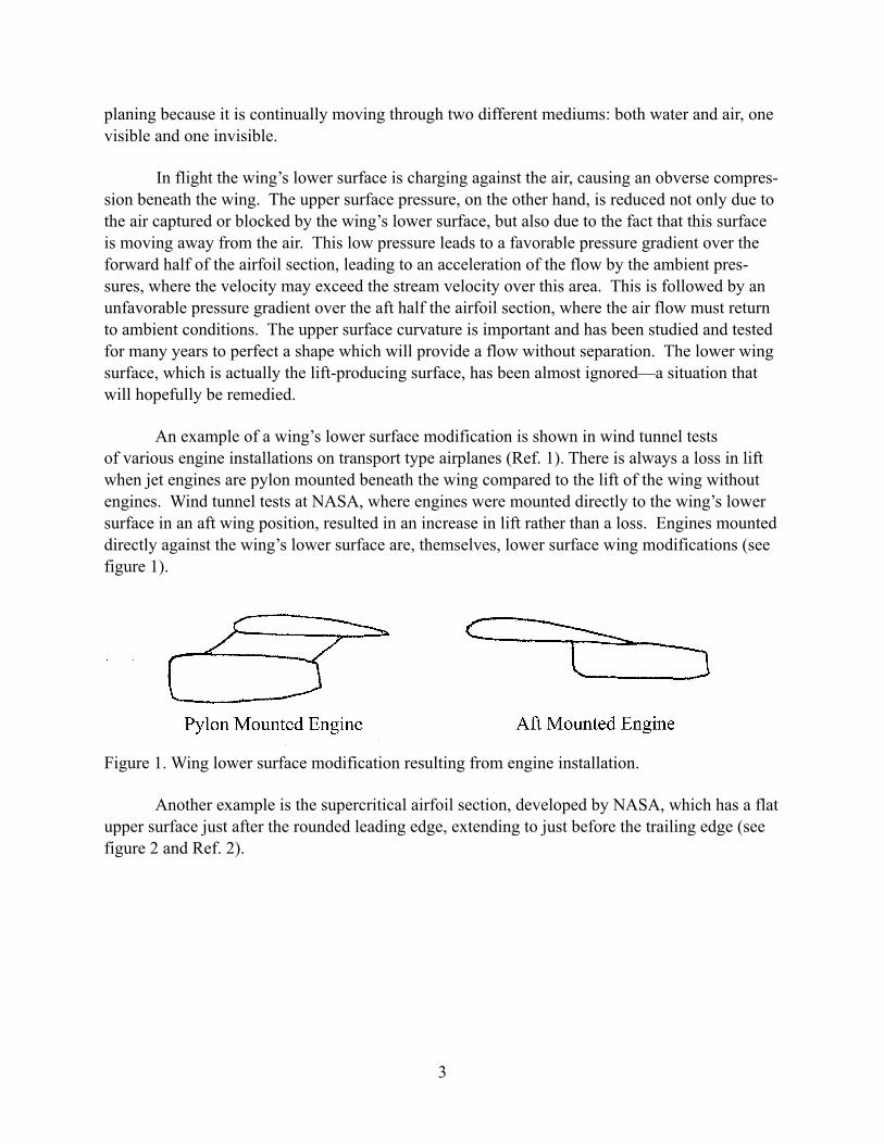
An example of a wing’s lower surface modification is shown in wind tunnel tests of various engine installations on transport type airplanes (Ref. 1). There is always a loss in lift when jet engines are pylon mounted beneath the wing compared to the lift of the wing without engines. Wind tunnel tests at NASA, where engines were mounted directly to the wing’s lower surface in an aft wing position, resulted in an increase in lift rather than a loss. Engines mounted directly against the wing’s lower surface are, themselves, lower surface wing modifications (see figure 1).
Figure 1. Wing lower surface modification resulting from engine installation.
Another example is the supercritical airfoil section, developed by NASA, which has a flat upper surface just after the rounded leading edge, extending to just before the trailing edge (see figure 2 and Ref. 2).
3
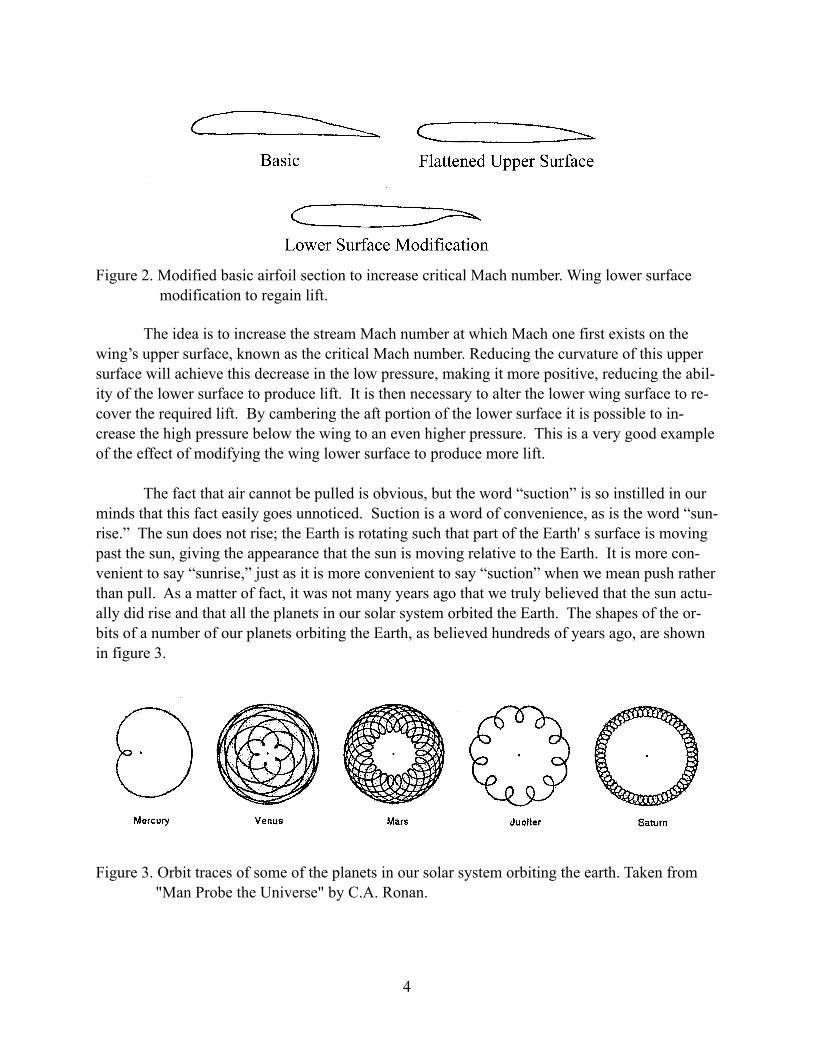
Figure 2. Modified basic airfoil section to increase critical Mach number. Wing lower surface modification to regain lift.
The idea is to increase the stream Mach number at which Mach one first exists on the wing’s upper surface, known as the critical Mach number. Reducing the curvature of this upper surface will achieve this decrease in the low pressure, making it more positive, reducing the abil-ity of the lower surface to produce lift. It is then necessary to alter the lower wing surface to re-cover the required lift. By cambering the aft portion of the lower surface it is possible to in-crease the high pressure below the wing to an even higher pressure. This is a very good example of the effect of modifying the wing lower surface to produce more lift.
The fact that air cannot be pulled is obvious, but the word “suction” is so instilled in our minds that this fact easily goes unnoticed. Suction is a word of convenience, as is the word “sun-rise.” The sun does not rise; the Earth is rotating such that part of the Earth' s surface is moving past the sun, giving the appearance that the sun is moving relative to the Earth. It is more con-venient to say “sunrise,” just as it is more convenient to say “suction” when we mean push rather than pull. As a matter of fact, it was not many years ago that we truly believed that the sun actu-ally did rise and that all the planets in our solar system orbited the Earth. The shapes of the or-bits of a number of our planets orbiting the Earth, as believed hundreds of years ago, are shown in figure 3.
Figure 3. Orbit traces of some of the planets in our solar system orbiting the earth. Taken from "Man Probe the Universe" by C.A. Ronan.
4
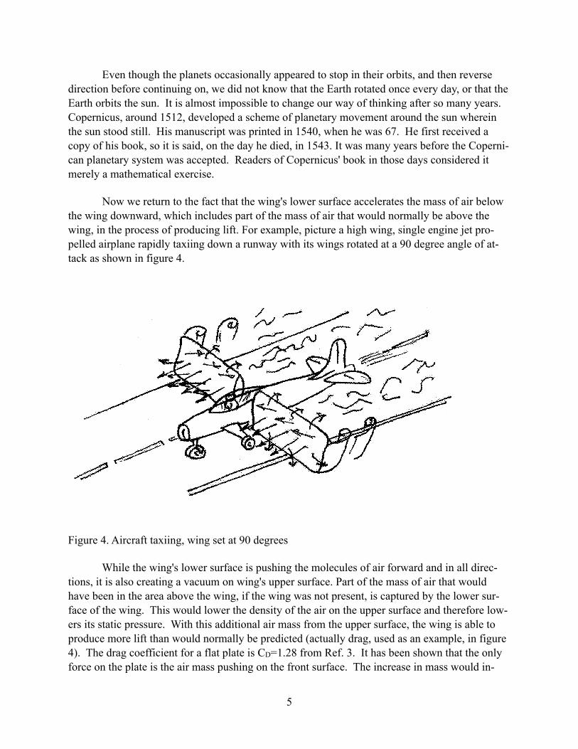
Even though the planets occasionally appeared to stop in their orbits, and then reverse direction before continuing on, we did not know that the Earth rotated once every day, or that the Earth orbits the sun. It is almost impossible to change our way of thinking after so many years. Copernicus, around 1512, developed a scheme of planetary movement around the sun wherein the sun stood still. His manuscript was printed in 1540, when he was 67. He first received a copy of his book, so it is said, on the day he died, in 1543. It was many years before the Coperni-can planetary system was accepted. Readers of Copernicus' book in those days considered it merely a mathematical exercise.
Now we return to the fact that the wing's lower surface accelerates the mass of air below the wing downward, which includes part of the mass of air that would normally be above the wing, in the process of producing lift. For example, picture a high wing, single engine jet pro-pelled airplane rapidly taxiing down a runway with its wings rotated at a 90 degree angle of at-tack as shown in figure 4.
Figure 4. Aircraft taxiing, wing set at 90 degrees
While the wing's lower surface is pushing the molecules of air forward and in all direc-tions, it is also creating a vacuum on wing's upper surface. Part of the mass of air that would have been in the area above the wing, if the wing was not present, is captured by the lower sur-face of the wing. This would lower the density of the air on the upper surface and therefore low-ers its static pressure. With this additional air mass from the upper surface, the wing is able to produce more lift than would normally be predicted (actually drag, used as an example, in figure 4). The drag coefficient for a flat plate is CD=1.28 from Ref. 3. It has been shown that the only force on the plate is the air mass pushing on the front surface. The increase in mass would in-
5

crease the force developed, while the associated decrease in pressure on the back surface reduces the resistance manifesting itself as part of the increase in lift on the front surface or the wing’s lower surface.
To summarize, the lower surface of a wing in motion accelerates a mass of air downward, and the air, in turn, reacts by pushing upward against the wing's lower surface, which is a reac-tion lift force. The wing's lower surface is actually planing on the molecules of air, similar to that of high-speed racing boat planing on the surface of water. As speed is increased, the bow of the boat usually rises, reducing the submerged surface area, which in turn reduces drag, but at the same time exposes the lower surface of the hull to the surrounding air. The boat is now planing on air as well as on water. The boat has no aerodynamic controls, like most gliders before the success of the Wright brothers. In many cases the boat’s center of gravity is in the aft-position, so the moment caused by the aerodynamic lift further increases the boat’s angle relative to the surface of the water, causing the boat, in some cases, to clear the water completely. It begins to roll to one side or the other due to the lack of lift similarity across the boat’s hull, such that the exposed hull area is now reduced to only that of the side of the boat. Unable to maintain the re-quired lift, the boat falls back into the water, usually disastrously.
A commercial transport airplane sitting at one end of a runway is given clearance for take off. The airplane starts accelerating along the runway until it reaches flying speed—the speed required, based on dynamic pressure and wing area, to lift the airplane from the ground. The pas-sengers feel themselves being pushed back against their seats when, in fact, the seats are actually pushing forward against their resting bodies. At flying speed the pilot pulls back on the control column causing the horizontal tail to angle downward, thereby increasing the angle of attack of the wing, exposing the lower surface of the wing to the air molecules in the up stream flight path. The low pressure on the wing's upper surface is a result of the blockage affected by the wing’s lower surface.
Once it is understood how a wing produces lift, how air acts and reacts, and the nature of the wing, lift is much less abstract and mysterious. In fact, the nature of lift will becomes obvi-ous, but still very interesting. The wing is actually a remarkable machine. The lower surface produces lift and, in the process, reduces the pressure on the wing’s upper surface, helping it generate lift. It is interesting to note that it is the action of the wing itself that produces both the high and low static pressures.
Lift Induced Wingtip Vortex
The lift-induced wingtip vortex is a by-product of lift and has absolutely nothing to do with the production of lift. Just how the wingtip vortex is created and why it persists so long af-ter the airplane has passed has long been a mystery. Now that it is recognized, physically, how the wing develops lift and that air can only be pushed and not pulled, the problems in aerody-namics are reduced by half. It becomes almost obvious just how the wingtip vortex is formed.
6
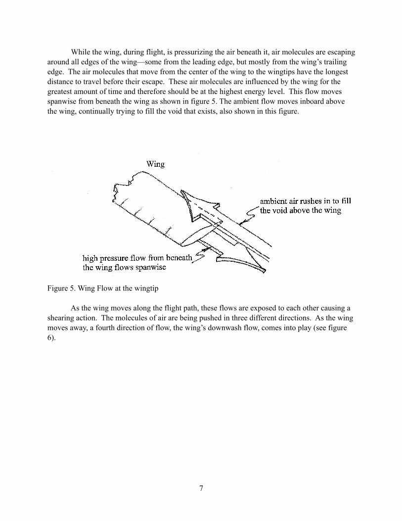
While the wing, during flight, is pressurizing the air beneath it, air molecules are escaping around all edges of the wing—some from the leading edge, but mostly from the wing’s trailing edge. The air molecules that move from the center of the wing to the wingtips have the longest distance to travel before their escape. These air molecules are influenced by the wing for the greatest amount of time and therefore should be at the highest energy level. This flow moves spanwise from beneath the wing as shown in figure 5. The ambient flow moves inboard above the wing, continually trying to fill the void that exists, also shown in this figure.
Figure 5. Wing Flow at the wingtip
As the wing moves along the flight path, these flows are exposed to each other causing a shearing action. The molecules of air are being pushed in three different directions. As the wing moves away, a fourth direction of flow, the wing’s downwash flow, comes into play (see figure 6).
7
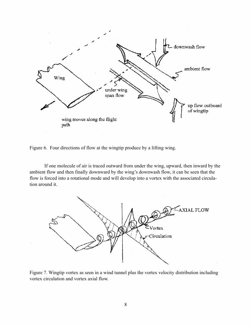
Figure 6. Four directions of flow at the wingtip produce by a lifting wing.
If one molecule of air is traced outward from under the wing, upward, then inward by the ambient flow and then finally downward by the wing’s downwash flow, it can be seen that the flow is forced into a rotational mode and will develop into a vortex with the associated circula-tion around it.
Figure 7. Wingtip vortex as seen in a wind tunnel plus the vortex velocity distribution including vortex circulation and vortex axial flow.
8
Wind tunnel measurements have shown that the vortex is fully developed within one half of the length of the tip chord behind the wing, rotating at a maximum speed of twenty five thou-sand (25,000) revolutions per minute. There is a sizable amount of energy in the vortex, which, as stated earlier, results in 35 to 40 percent of the total drag of the airplan, in the form of induced drag. There is an overall change in the flow field experienced by the wing caused by the vortex resulting in induced drag.
Vortex Persistence
When a vortex is formed just behind the wingtip, it is stationary relative to the earth and rotating at its highest RPM. The vortex’s internal pressure at this point is also at its lowest value due to centrifugal force. With time, air friction reduces this rotational speed resulting in an in-crease in internal pressure. The vortex will also increase in diameter as it slows down, to con-serve angular momentum, resulting in an increase in internal volume and an associated increase in internal pressure. A pressure gradient exists between the continually forming wingtip vortex as the airplane moves along its flight path and the stationary vortex left behind. This pressure gradient causes an axial flow, which is approximately 15 percent of the airplane’s speed in the flight direction. The axial flow, moving through the stationary vortex, adds vectorally to the rota-tion of vortex, raising its energy level, which is responsible for the well-known persistence of the vortex long after the airplane has passed.
It has been shown in the NASA Langley Vortex Research Facility that interrupting this vortex axial flow will cause the vortex to collapse, changing it from a stable rotational flow to a leaner, turbulent type flow which is known to dissipate very rapidly.
Knowing how the vortex develops and the secret to its longevity is key to eliminating the vortex, improving the efficiency of the aircraft. In doing so, the first benefit will be a sizable in-crease in fuel economy. The induced drag or, actually, the wingtip vortex drag will be near zero.
Each time I see a transport airplane climbing majestically, seemingly effortlessly toward the heavens with its thin sharp wings slicing through the air like dueling foils (from which the wing gets its title: "airfoil") it always comes to mind that 35 to 40 percent of the airplane's enor-mous power is unnecessarily wasted on vortex drag. This drag is similar to that which an auto-mobile might experience driving at highway speed with both front doors braced in the wide-open position. Forget the gas mileage….
Another factor, far more important than fuel economy, is the fact there will be no more vortex hazard to following airplanes, particularly in the terminal area, now that the lift induced vortex can be eliminated. When jumbo-jet airplanes were first introduced some years ago, it was necessary to increase the separation distance for following airplanes from the normal one minute to eight minutes or more in order to avoid being upset by the tornado-like vortex flow produced by such heavy airplanes. The strength of the vortex is a direct function of airplane weight. If an airplane should enter this circular rotational flow there will be an up flow on one wing panel and
9

a powerful down flow on the other, producing positive lift on one wing panel and negative lift on the other. This combination would cause the airplane to rotate at a rate that would, more than likely, exceed the power of the lateral controls of the craft. If in a landing mode, at low landing velocity (thereby increasing the angle of attack caused by the vortex as well as reduce the effec-tiveness of the lateral controls), the airplane could be rotated 180 degrees, possibly crashing up-side down on the runway with little chance for survivors.
The material presented is based on analysis of the actual movement of air molecules through aerodynamic measurements and is entirely different from the theoretical descriptions of today. This more realistic view of aerodynamic flows relative to the airplane will offer a greater understanding of actual flight.
It has been said that during our quest for reality, even if nature is stripped of all its dis-guises, the evolving picture fleets further from our experience and we are less able to recognize true reality. This is as it was with the planetary orbit traces shown earlier, with the Earth at their centers. These traces suggest that the planets move in every direction, and this was believed by humanity to be true and accurate for many years before it was revealed that the sun, not the Earth is the center of our solar system.
The low pressure on the wing’s upper surface is said to produce lift, enabling the airplane to fly. This is a theoretical statement which is not, in any way, grounded in reality. It has been said that once we accept a mathematical description of aerodynamics, we lose sight of the way flight is actually achieved.
10

References
1. Abeyounis, William K.; and Patterson, James C. Jr.: Effect of Location of Aft-. Mounted Nacelles on Longitudinal Aerodynamic Characteristics of a High-Wing Transport Airplane. NASA TP 3047, December 1990.
2. Whitcomb, Richard T.: Review of NASA Supercritical Airfoils Proceeding, 9th Congress of the International Council of the Aeronautical Sciences (ICAS). Haifa, Israel, 25-30 August 1974.
3. Dommasch, Daniel 0.: Airplane Aerodynamics. Published 1951, page 148.
References of Vortex Attenuation
Wake Vortex Minimization Symposium. Washington, D.C. February 25-26,1976. NASA SP409.
Patterson, James C., Jr.; and Jordan, Frank L. Jr.: Thrust-Augmented Vortex Attenuation. (Page 251)
Patterson, James C., Jr.; Hasting, Earl C., Jr.; and Jordan, Frank L., Jr.: Ground Development and Flight Correlation of the Vortex Attenuation Spline Device. (Page 271)
Patterson, James C. Jr.; and Flechner, Stuart G.: An Exploratory Wind-Tunnel Investigation of the Wake Effect of a Panel Tip-Mounted Fan-Jet Engine on the Induced Vortex. NASA TN D-5729, May 1970.
Patterson, James C., Jr., NASA, Hampton, VA; and Bartlett, Glynn R., ViGY AN Research Asso-ciates: Effect ,of a Wing-Tip Mounted Pusher Turboprop on the Aerodynamic Characteristics of a Semi-Span Wing. AIAA-85-1347.
Hasting, Earl C., Jr.;.Patterson, James C., Jr.; Shanks, Richard E.; Champine, Richard A.; Cope-land, William L.; and Yound, D.C.: Development and Flight Test of Vortex Attenuating Splines. NASA TN C8083, December 1975.
Patterson, James C. Jr., NASA Langley Research Center, Hampton, VA: Lift-Induced Wing-Tip Vortex Attenuation. AIAA 12th Aerospace Sciences Meeting, Washington, D.C., January 30 -February 1, 1974. AIAA 74-38.
11