Embed Size (px)
Citation preview
ASHRAE - Variable Speed Drives
By Dan Watkins, LEED BD+C
Bornquist, Inc.
Adjustable Frequency Drive Fundamentals
• How does a VFD actually work • VS Pumping Analysis • VS Pumping Features • Harmonics • VFDs and Motors

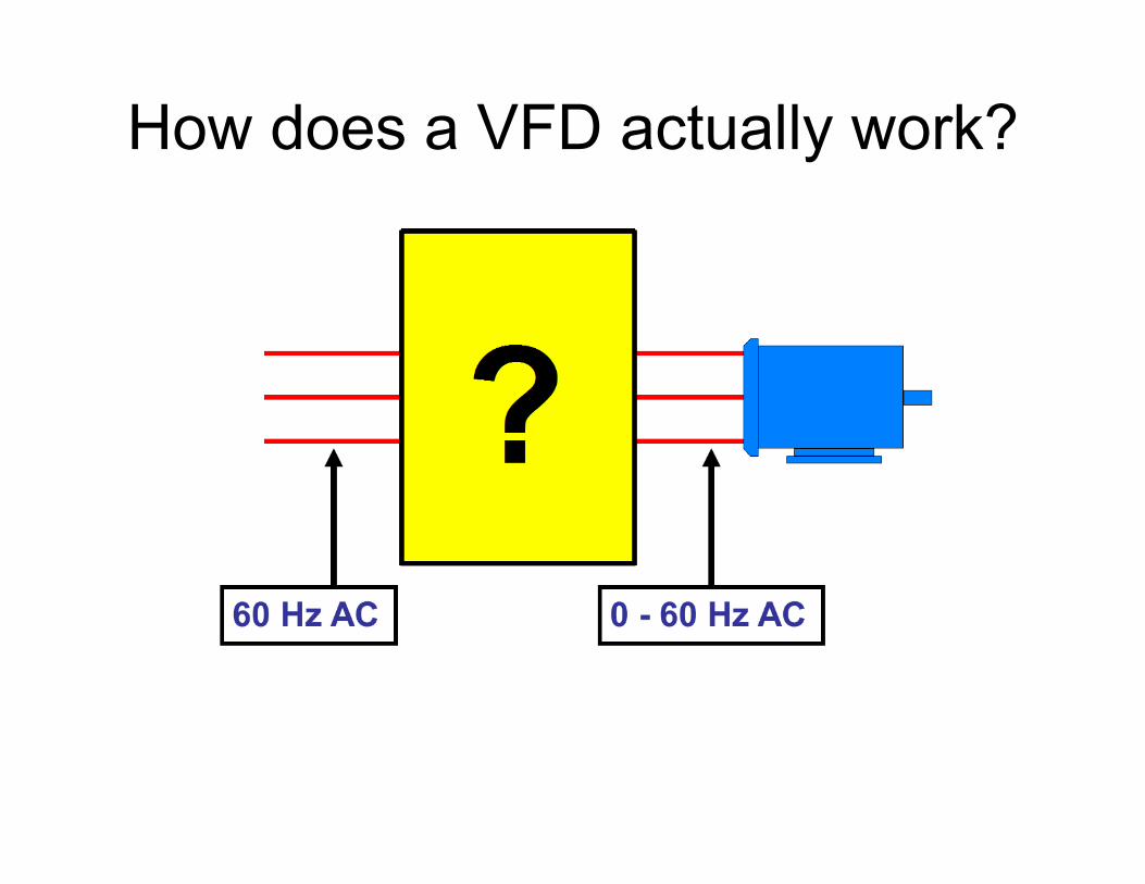
How does a VFD actually work?
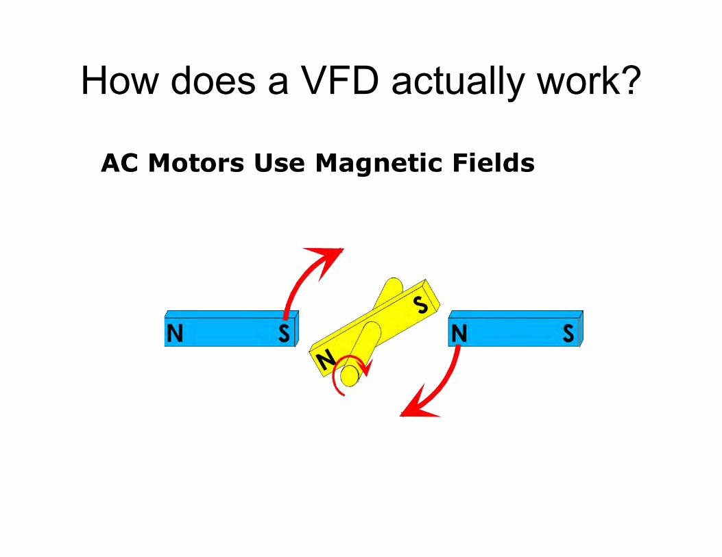
How does a VFD actually work?
Frequency Controls Motor Speed
How does a VFD actually work?
How does a VFD actually work?

Converts AC to DC, then DC to AC
460 V, 60 Hz 640 V, DC 307 V, 40 Hz

Basic Drive
Diodes Change AC to DC
Capacitors Filter the DC
Transistors Switch DC to AC
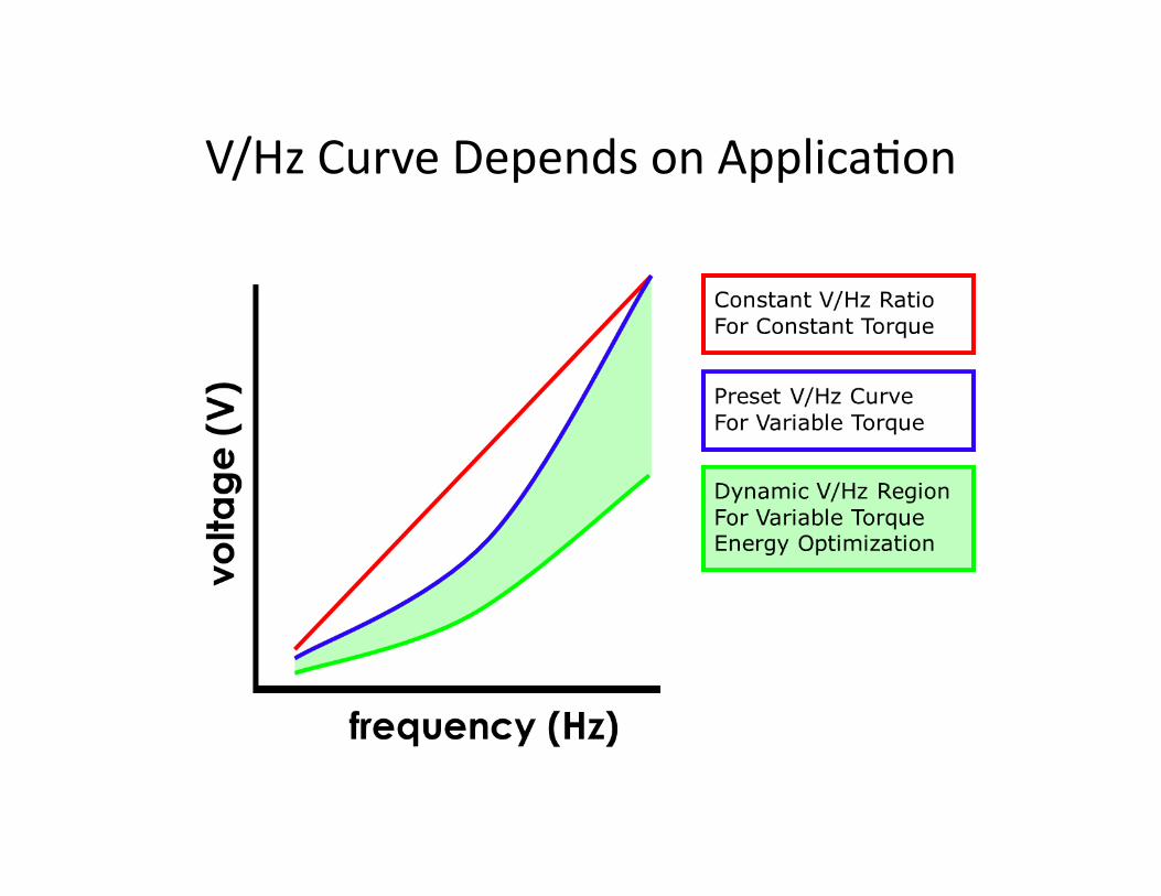
V/Hz Curve Depends on ApplicaCon

Extended Frequency OperaCon

Extended Frequency OperaCon

Extended Frequency OperaCon
So, why do we want to do variable speed pumping?
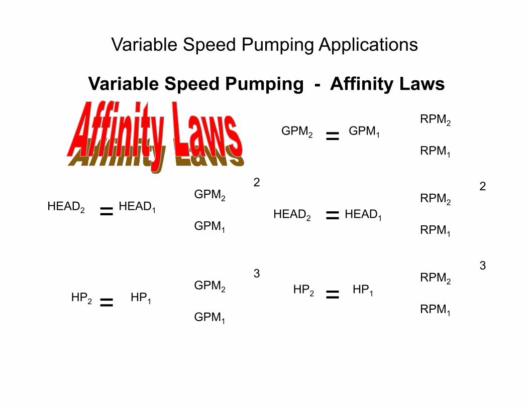
GPM2 GPM1
HEAD2
RPM2
RPM1
HEAD1
HP2 HP1
=
= =
=
=
RPM2
RPM1
RPM2
RPM1 HP2 HP1
GPM2
GPM1
GPM2
GPM1
HEAD2 HEAD1
22
33
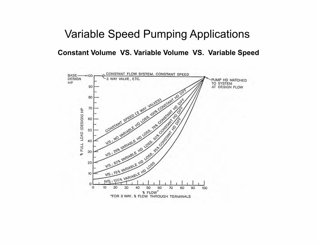
Variable Speed Pumping Applications
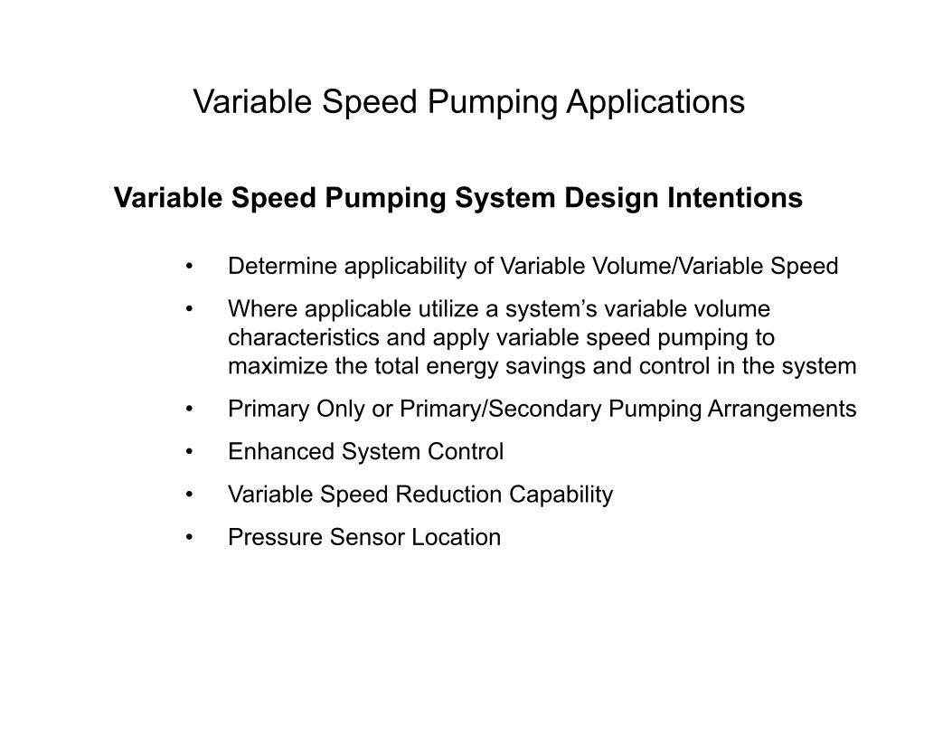
• Determine applicability of Variable Volume/Variable Speed
• Where applicable utilize a system’s variable volume characteristics and apply variable speed pumping to maximize the total energy savings and control in the system
• Primary Only or Primary/Secondary Pumping Arrangements
• Enhanced System Control
• Variable Speed Reduction Capability
• Pressure Sensor Location
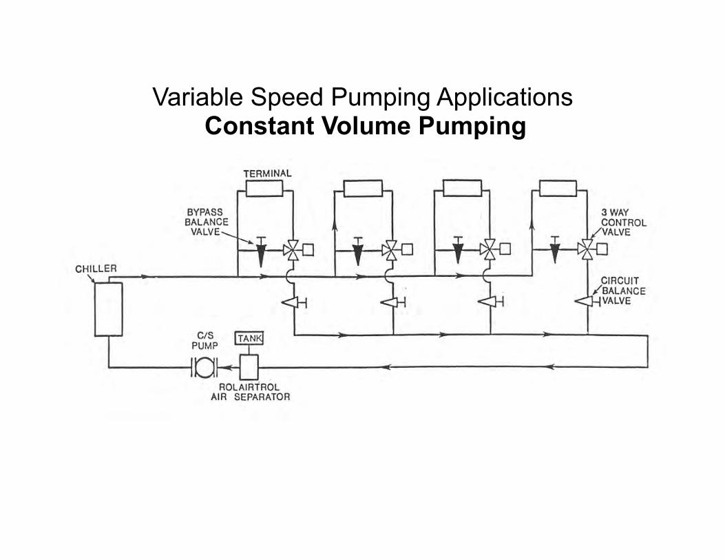
Variable Speed Pumping Applications
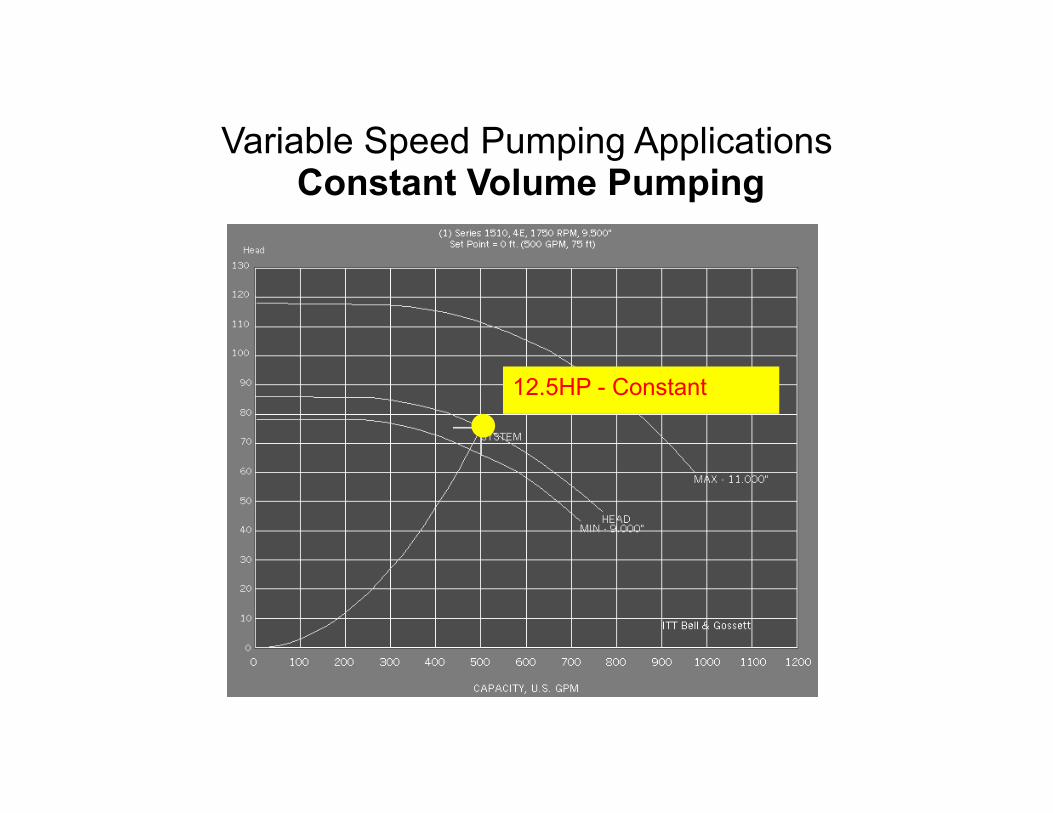
Variable Speed Pumping Applications
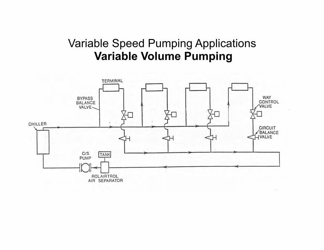
Variable Speed Pumping Applications
12.5HP - Constant
Variable Speed Pumping Applications

Variable Speed Pumping Applications
15HP 10HP
12.5HP - 7.5HP Depending on Flow

Variable Speed Pumping Applications

Variable Speed Pumping Applications
12.5HP
1.6HP
HP2 12.5 = 900 1800
3
HP1 = 1.6 HP
Variable Speed Pumping Applications

Variable Speed Pumping ApplicaCons -‐ Applicability
The question of applicability of Variable Volume/Variable Speed on your system is based on the system’s inherent operating characteristics. In system’s with generally steady load characteristics and/or limited volume variation - Variable Speed is not generally applied due to poor payback calculations. In system’s with varying load characteristics and greater volume variation - Variable Speed is generally applied, based on a payback analysis.

Variable Speed Pumping ApplicaCons -‐ Sensor LocaCon
ΔP Sensor/Transmitter
SOU
RC
E
SOU
RC
E
ΔP Sensor/ Transmitter
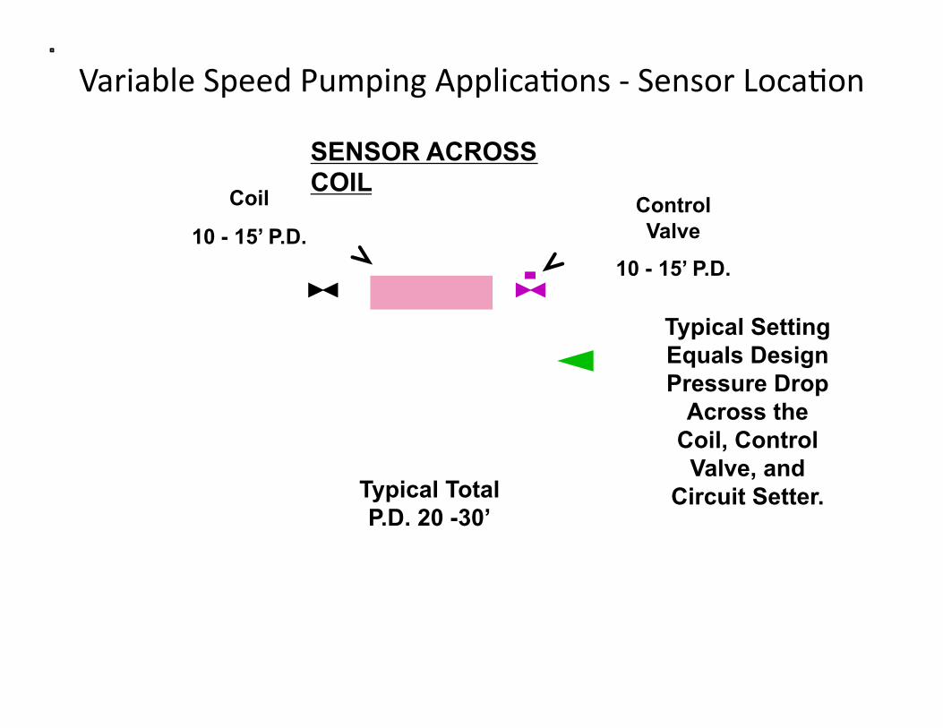
Variable Speed Pumping ApplicaCons -‐ Sensor LocaCon
Coil
10 - 15’ P.D. Control Valve
10 - 15’ P.D.
Typical Total P.D. 20 -30’
Typical Setting Equals Design Pressure Drop
Across the Coil, Control Valve, and
Circuit Setter.

Variable Speed Pumping ApplicaCons -‐ Sensor LocaCon
SOU
RC
E
SOU
RC
E
ΔP Sensor/ Transmitter
Typical Setting Equals Total Pump Head Minus Noted
Pressure Drops
Pump Trim 5’ P.D.
Air Separator
3’ - 5’ P.D.
Piping Loss
3’ - 5’ P.D.
PumpOverhead
0 - 15% P.D.

Variable Speed Cost Savings
• Easy Pump Balancing • Variable Flow Systems
• Pressure Booster Packages

Variable Speed Pumping Easy Pump Balancing
Pump Selected at:
1000 GPM @ 100’ 40 HP required.
Duty Point: 30 HP
Oversized by 15%
15’ head on TDV
X

Variable Speed Pumping

Variable Speed Pumping
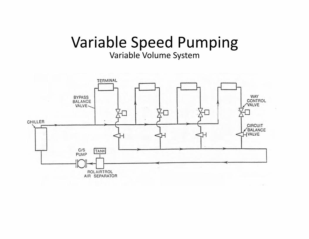
Variable Speed Pumping Variable Volume System
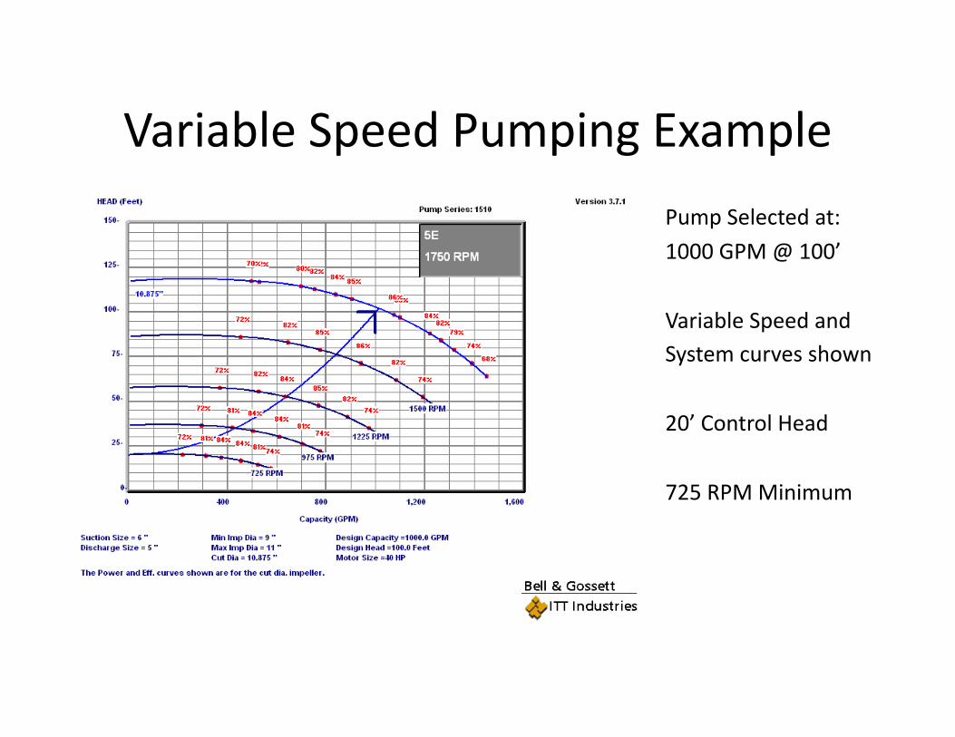
Variable Speed Pumping Example
Pump Selected at:
1000 GPM @ 100’
Variable Speed and System curves shown
20’ Control Head
725 RPM Minimum

Variable Speed Pumping Example
PE Motor

Variable Speed Pumping Example
PE Motor

Variable Speed Pressure BoosCng
• Height of building – 12 stories • 150 _. staCc li_ • 30 PSI City pressure • 30 PSI required at the top • 50’ piping pressure drop at
design flow
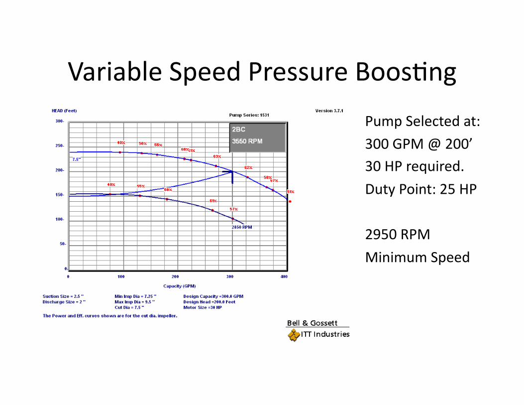
Variable Speed Pressure BoosCng
Pump Selected at:
300 GPM @ 200’ 30 HP required.
Duty Point: 25 HP
2950 RPM
Minimum Speed
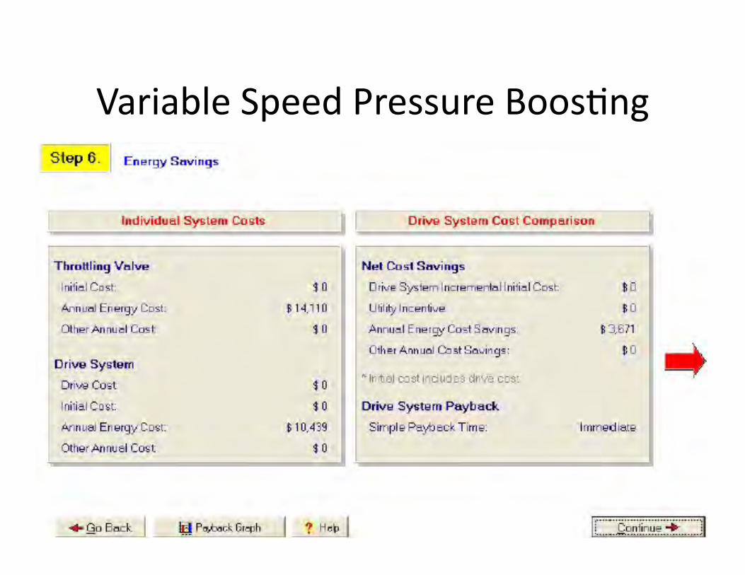
Variable Speed Pressure BoosCng

Application-Specific Capabilities Pumps
Compressors

Flying Start
• Synchronizes the drive to the speed of a coasting fan
• Searches for the fan’s speed in both directions
• Applies DC braking if needed
• Provides a smooth start

Vibration Avoidance
• Avoids speed that can cause mechanical resonant vibration
• Up to four frequency bands of individual sizes
• Simple, prompted automated setup

Other Pump-Protection Functions
• Dry pump detection • Over-flow (“end of curve”)
protection

Power Line Harmonics – Their Cause and Solutions

What are Harmonics? A sinusoidal waveform is a pure frequency All waveforms have a fundamental frequency Harmonics are integer multiples of the fundamental
frequency The first harmonic is the fundamental frequency

What is Harmonic Distortion? Harmonic distortion results when harmonics currents are combined
with a fundamental frequency The resulting waveform is no longer a pure sine wave Harmonic currents operate at the same time as the fundamental, but
at faster rate Harmonic currents are additive, producing a “distorted” sine wave
Fundamental = 60Hz
5th Harmonic = 300Hz

Why are Harmonics a concern? Overheating of power distribution transformers Overheating of conductors, especially neutral
wiring Overheating of induction motors Torque reduction of induction motors Overheating of power factor correction
capacitors Nuisance tripping of circuit breakers Blown fuses

Why are Harmonics a concern?
• Carrier current signals – Lighting systems (Leviton) – Some security systems
• Sensitive electronic equipment – Communication – Research – Computers – Airport Electronics – Medical – Security
• Stand-by generators

What Causes Harmonics?
NON-LINEAR LOADS - Loads which do not draw sinusoidal current from the line
Non-incandescent lighting Computers Uninterruptible power supplies Telecommunications equipment Copy machines Battery chargers Electronic variable speed drives
Any load with an AC to DC power converter

• For a typical 6 pulse inverter, these multiples are: – Fundamental = 60 Hz – 5th Harmonic = 60 x 5 = 300 Hz – 7th Harmonic = 60 x 7 = 420 Hz – 11th Harmonic = 60 x 11 = 660 Hz – 13th Harmonic = 60 x 13 = 780 Hz – 17th Harmonic = 60 x 17 = 1,020 Hz
Harmonics

One Drive in Different Buildings
“Strong” Power Line • Total harmonic voltage
distortion 1.1%
“Weak” Power Line • Total harmonic voltage
distortion 5.1%

IEEE 519-1992
• Designed to protect the utility power grid • Measured at the “Point of Common Coupling” (PCC)
– “This recommendation … focuses on the point of common coupling (PCC) with the consumer-utility interface. … some harmonic effects are unavoidable at some points in the system.” (IEEE Std 519-1992, sec. 10.1)
• The PCC is not at the wiring to an individual device

Drive Manufactures Addressing Harmonics
• Some just ignore the problem • Build in DC link chokes • Built in line reactors • Build special 12 and 18 pulse drives • Optional separate filters
Product Selection Goal: Select products that give you performance without excess cost
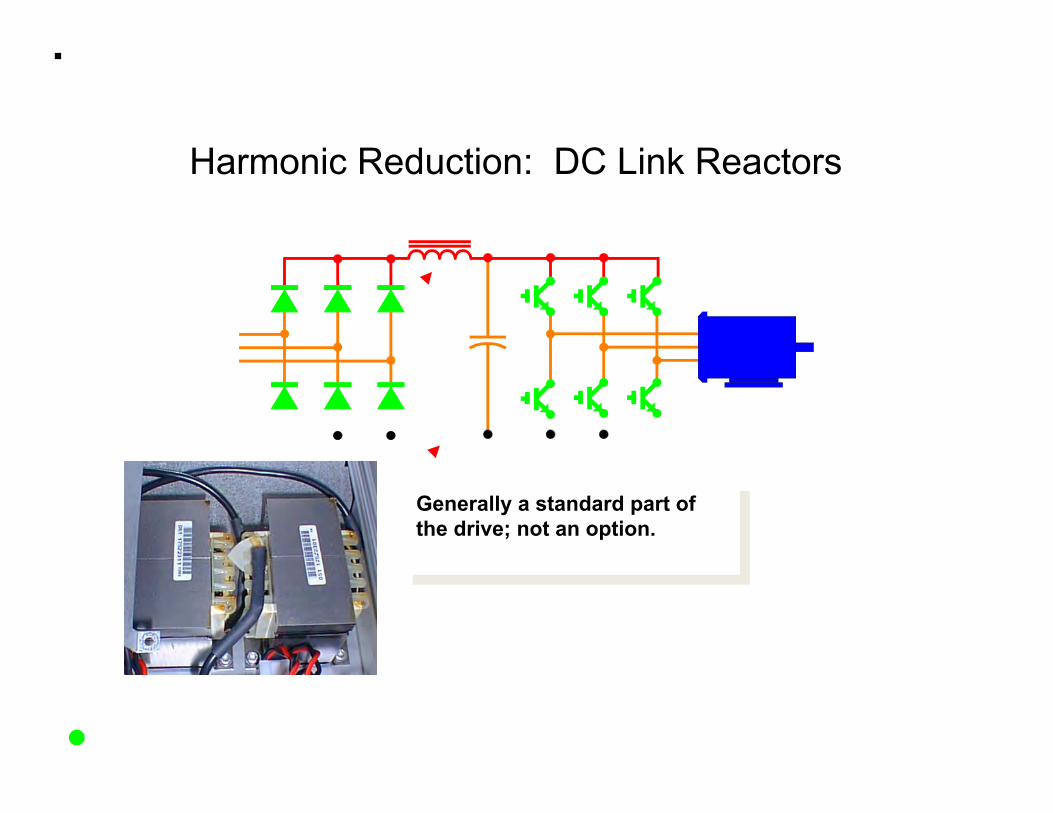
Harmonic Reduction: DC Link Reactors
Generally a standard part of the drive; not an option.
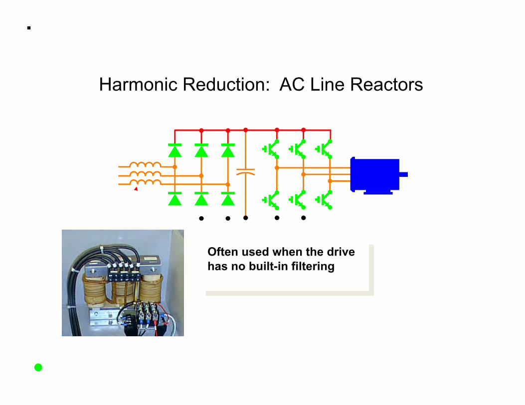
Harmonic Reduction: AC Line Reactors
Often used when the drive has no built-in filtering
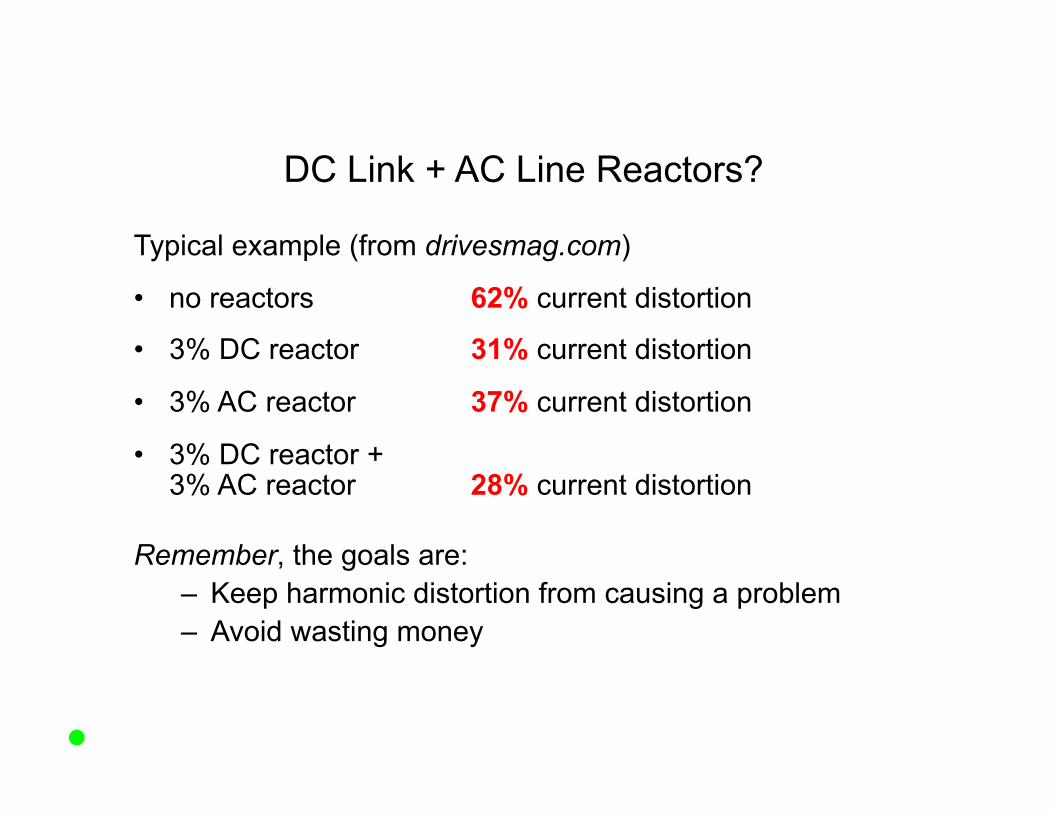
DC Link + AC Line Reactors?
Typical example (from drivesmag.com)
• no reactors 62% current distortion
• 3% DC reactor 31% current distortion
• 3% AC reactor 37% current distortion
• 3% DC reactor + 3% AC reactor 28% current distortion
Remember, the goals are: – Keep harmonic distortion from causing a problem – Avoid wasting money

12-Pulse (and Higher) Rectifier
• Theoretically eliminates the 5th and 7th harmonics
• Uses two sets of input diodes
to the rest of the drive
to the power line
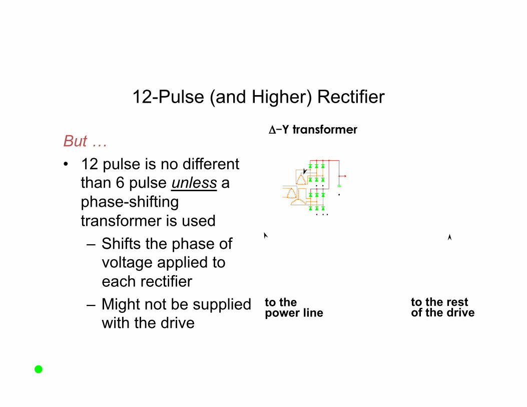
12-Pulse (and Higher) Rectifier
But … • 12 pulse is no different
than 6 pulse unless a phase-shifting transformer is used – Shifts the phase of
voltage applied to each rectifier
– Might not be supplied with the drive
Δ-Y transformer
to the power line
to the rest of the drive
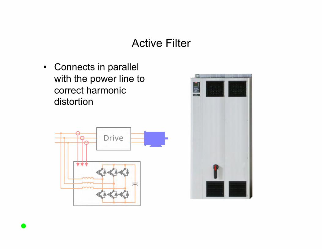
Active Filter
• Connects in parallel with the power line to correct harmonic distortion

Comparing All Harmonic Solutions
Adjustable Frequency Drives and Motor InteracCon

Drive and Motor Interaction
• Audible Motor Noise • Motor Overheating • Motor Insulation Stress • Motor Bearing Damage

Audible Motor Noise
• Caused by the pulses of electrical energy that the drive uses to power the motor
• The loudness depends on – Motor design – Pulse frequency – Motor current
Drive and Motor Interaction
• Audible Motor Noise • Motor Overheating • Motor Insulation Stress • Motor Bearing Damage
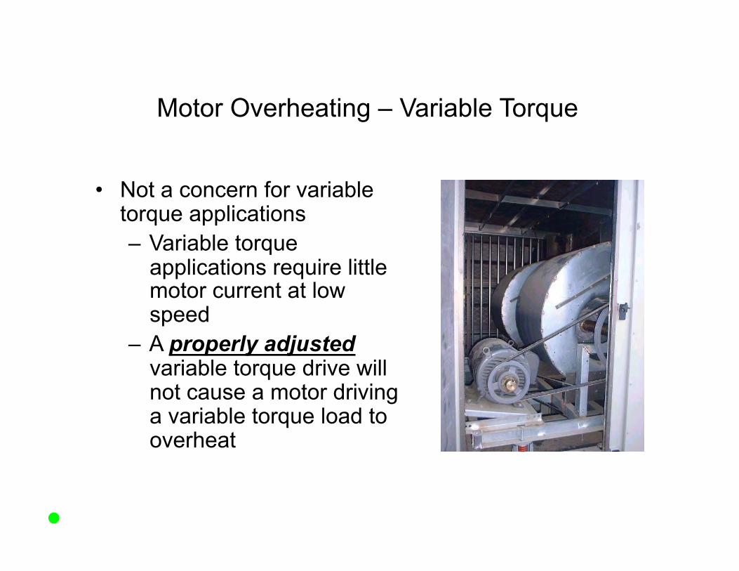
Motor Overheating – Variable Torque
• Not a concern for variable torque applications – Variable torque
applications require little motor current at low speed
– A properly adjusted variable torque drive will not cause a motor driving a variable torque load to overheat

Drive and Motor Interaction
• Audible Motor Noise • Motor Overheating • Motor Insulation Stress • Motor Bearing Damage

Motor Insulation Stress
• Shows up first as an over current trip, ground fault trip or fuse blowing in bypass
• Motor insulation looks and smells good
• “Megger” or “Hi Pot” test shows shorting between windings or from a winding to ground

Cause of Motor Insulation Stress
• When current is switched, a coil generates a “back voltage”
• The faster the change (dV/dt), the greater the “back voltage”
• This can arc through motor insulation

Minimizing Motor Insulation Stress
• Better motor insulation – Standard Motor
NEMA MG 1, Part 30: 1000 V peak voltage, 2 µs rise time
– Special-Purpose Motor NEMA MG 1, Part 31: 1600 V peak voltage, 0.1 µs rise time

Minimizing Motor Insulation Stress
• Better motor insulation • Short wire length to the motor
The longer the motor leads, the less the effect of the diodes.

Short Wire Length to the Motor
10 Foot Motor Lead
90 Foot Motor Lead
210 Foot Motor Lead
200 V/div – vertical; 0.2 µs/div – horizontal
Waveforms are for a “soft switching” drive
1000 V

Slow Switching Power Components
So_ Switching IGBT Standard IGBT
90 ft motor leads
200 V/div – vertical; 0.5 µs/div – horizontal
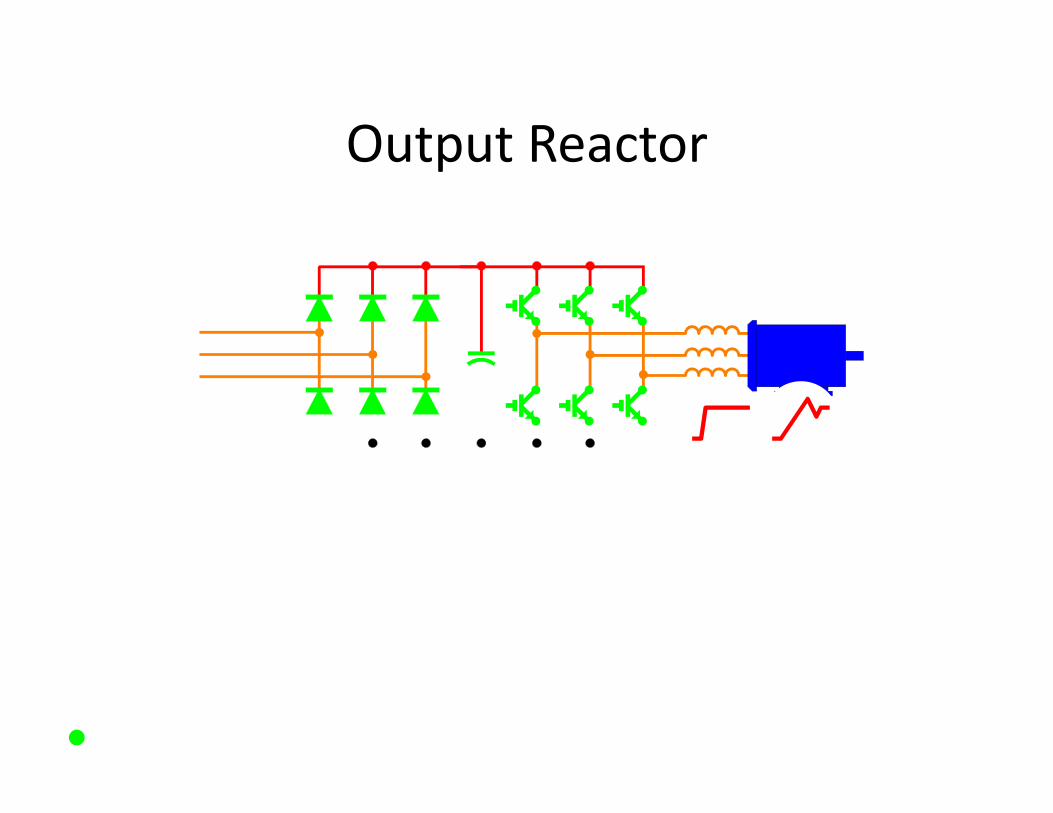
Output Reactor
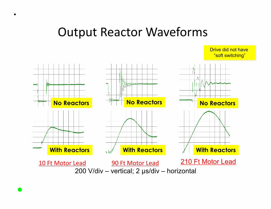
Output Reactor Waveforms
10 Ft Motor Lead 90 Ft Motor Lead 210 Ft Motor Lead 200 V/div – vertical; 2 µs/div – horizontal
Drive did not have “soft switching”
No Reactors No Reactors No Reactors
With Reactors With Reactors With Reactors
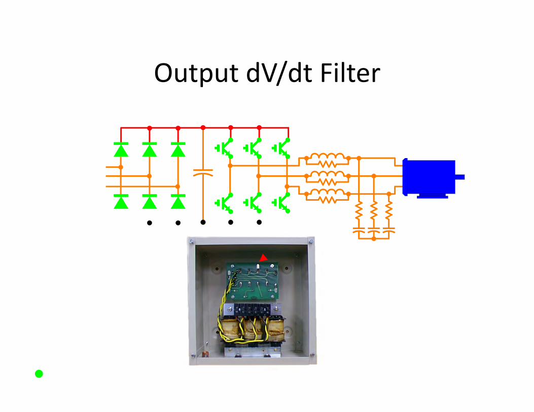
Output dV/dt Filter
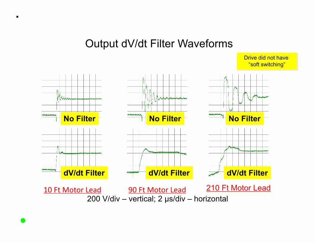
Output dV/dt Filter Waveforms
10 Ft Motor Lead 90 Ft Motor Lead
No Filter No Filter No Filter
dV/dt Filter dV/dt Filter dV/dt Filter
210 Ft Motor Lead 200 V/div – vertical; 2 µs/div – horizontal
Drive did not have “soft switching”
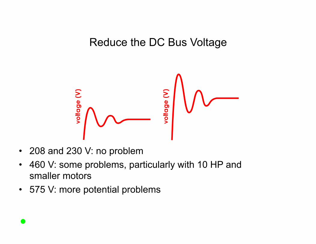
Reduce the DC Bus Voltage
• 208 and 230 V: no problem • 460 V: some problems, particularly with 10 HP and
smaller motors • 575 V: more potential problems

Drive and Motor Interaction
• Audible Motor Noise • Motor Overheating • Motor Insulation Stress • Motor Bearing Damage

Motor Bearing Damage
• This can cause a “washboard” pattern to be etched into the bearings
• Capacitive coupling can couple voltage from the stator to the rotor
• If this gets too high, voltage can discharge through the motor bearings

Motor Bearing Damage Solutions
• Reduced motor peak voltage – Drives which reduce motor insulation stress also
reduce the possibilities of bearing damage
Motor Bearing Damage Solutions
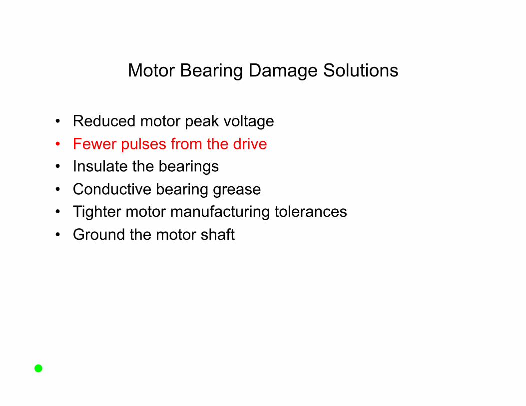
• Reduced motor peak voltage • Fewer pulses from the drive • Insulate the bearings • Conductive bearing grease • Tighter motor manufacturing tolerances • Ground the motor shaft
Motor Bearing Damage Solutions
• Reduced motor peak voltage • Fewer pulses from the drive • Insulate the bearings • Conductive bearing grease • Tighter motor manufacturing tolerances • Ground the motor shaft
Motor Bearing Damage Solutions
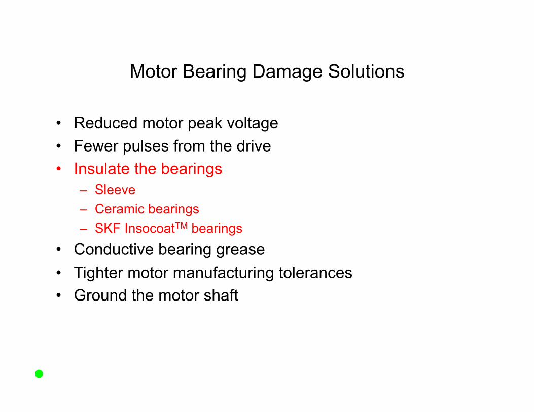
• Reduced motor peak voltage • Fewer pulses from the drive • Insulate the bearings
– Sleeve – Ceramic bearings – SKF InsocoatTM bearings
• Conductive bearing grease • Tighter motor manufacturing tolerances • Ground the motor shaft

Motor Bearing Damage Solutions
• Reduced motor peak voltage • Fewer pulses from the drive • Insulate the bearings • Conductive bearing grease • Tighter motor manufacturing tolerances • Ground the motor shaft
Motor Bearing Damage Solutions
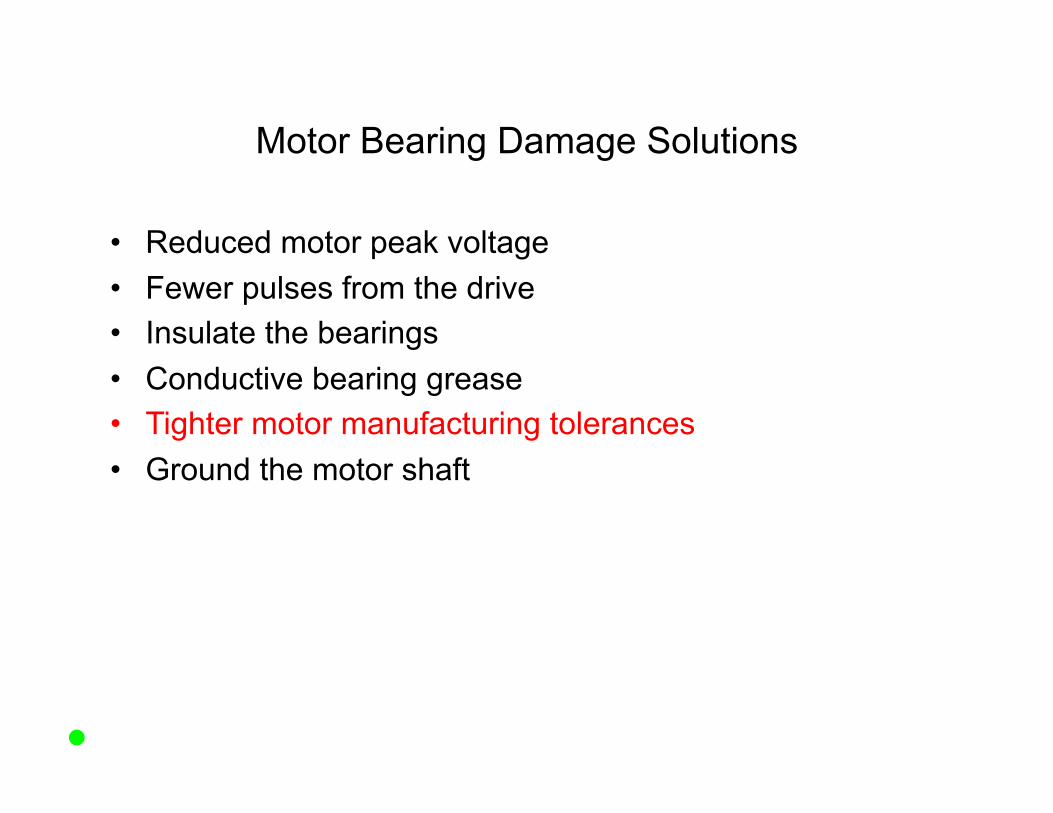
• Reduced motor peak voltage • Fewer pulses from the drive • Insulate the bearings • Conductive bearing grease • Tighter motor manufacturing tolerances • Ground the motor shaft
Motor Bearing Damage Solutions
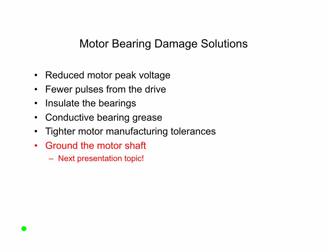
• Reduced motor peak voltage • Fewer pulses from the drive • Insulate the bearings • Conductive bearing grease • Tighter motor manufacturing tolerances • Ground the motor shaft
– Next presentation topic!

Thank You! Questions?


![Star Trek Pc Manual 021213[1]](https://img.dokumen.tips/doc/110x75/577cddcc1a28ab9e78adc384/star-trek-pc-manual-0212131.jpg)


