Embed Size (px)
Citation preview

ICT EU OneFIT
OneFIT Deliverable D2.1 1/72
Business scenarios, technical challenges and system requirements – D2.1
Project Number: ICT-2009-257385
Project Title: Opportunistic networks and Cognitive Management Systems for Efficient Application Provision in the Future Internet - OneFIT
Document Type: Deliverable
Contractual Date of Delivery: 31.10.2010
Actual Date of Delivery: 29.10.2010
Editors: O. Moreno
Participants: See contributors’ table
Workpackage: WP2
Estimated Person Months: 32 PMs
Nature: PU1
Version: 1.14
Total Number of Pages: 72
File: OneFIT_D2.1_20101031
Abstract
This document contains a detailed description of the working scenarios that will be used as a basis for the research to be carried out in OneFIT. Through the definition of target applications, business aspects and use cases, the technical challenges of the project are extracted. These challenges, along with a business model description and a security risks analysis, lead to the identification of the system requirements that guarantee that the OneFIT project will achieve its objectives.
Keywords List Opportunistic networks, business models, scenarios, system requirements, technical challenges, opportunistic capacity extensions, opportunistic coverage extensions, infrastructureless networks, traffic aggregation, mobile network operator.
1 Dissemination level codes: PU = Public
PP = Restricted to other programme participants (including the Commission Services) RE = Restricted to a group specified by the consortium (including the Commission Services) CO = Confidential, only for members of the consortium (including the Commission Services)

ICT EU OneFIT
OneFIT Deliverable D2.1 2/72
Executive Summary
The OneFIT project [1] is a collaborative research project that aims to design and validate an opportunistic network (ON) solution that enhances wireless service provision and extends the access capabilities for the Future Internet era. The OneFIT solution envisages a cognitive, context-aware system approach that allows higher resource utilization with lower costs and a more efficient management.
This document presents the functional scenarios for the project and derives the consequent system requirements, gathering the work performed in the tasks T2.1, Scenarios and use cases and T2.2, Technical challenges and requirements of Work Package 2.
Initially, a qualitative analysis of the business background related to opportunistic networking and the business models that will allow future exploitation of the system is presented. This work gathers all the common issues identified during T2.1 development.
Next, five different scenarios have been identified and are described in the following chapters. Each description includes a technical proposal and a preliminary assessment of the expected outcomes from the implementation of the solution:
Scenario 1 “Opportunistic coverage extension” describes a situation in which a device cannot connect to the network operator’s infrastructure, due to lack of coverage or a mismatch in the radio access technologies. The proposed solution includes an additional connected user that, by creating an opportunistic network, establishes a link between the initial device and the infrastructure, and acts as a data relay for this link.
Scenario 2 “Opportunistic capacity extension” depicts a situation in which a device cannot access the operator infrastructure due to the congestion of the available resources at the serving access node. The proposed solution proposes the redirection of the access route through an opportunistic network that avoids the congested network segment.
Scenario 3 “Infrastructure supported opportunistic ad-hoc networking” shows the creation of a localised, infrastructureless opportunistic network among several devices for a specific purpose (Peer-to-peer communications, home networking, location-based service providing, etc.). Infrastructure governs the ON creation and benefits from the local traffic offloading, as well as develops new opportunities for service providing.
Scenario 4 “Opportunistic traffic aggregation in the radio access network” describes the usage of a localised opportunistic network among several devices, in order to share a reduced number of infrastructure links towards a remote service-providing server or database. This situation allows some degree of traffic aggregation and caching that is useful to improve the overall network performance.
Scenario 5 “Opportunistic resource aggregation in the backhaul network” depicts how opportunistic networks can be used to aggregate both backhaul bandwidth and processing/storage resources on access nodes. In this case, the ON is created over access points rather than user terminals, thus offering a new focus on system performance improvement.
The document continues with the identification of the technical challenges that should be addressed during the OneFIT development phases, and the subsequent system requirements that have been derived from them.
Finally, a review of the state of the art in the context of opportunistic networks and cognitive management is presented, and used to derive a functional description of the envisaged solution, the expected outcomes and the criteria used to assess its performance.

ICT EU OneFIT
OneFIT Deliverable D2.1 3/72
Revision History
Revision Date Author(s) Description
0.1 21/09/2010 TID First draft of ToC
1.0 04/10/2010 [All WP2 partners]
First stable version to be commented at Plenary Meeting
1.1 05/10/2010 TID Contribution from IFX added
1.2 07/10/2010 TID Reviews and new structure from Plenary Meeting
1.3 13/10/2010 ALUD Section 6 reworked
1.4 15/10/2010 NTUK, VTT Sections 3 and 4 reworked
1.5 15/10/2010 UPC, UNS Section 8 reworked
1.6 15/10/2010 UPRC Section 5 reworked
1.7 17/10/2010 EIT+ Section 7 reworked
1.8 19/10/2010 TID Integrated Version for review / PhC 21.10
1.9 21/10/2010 UPC Comments inserted
1.10 21/10/2010 NTUK Section 3 updated
1.11 22/10/2010 ALUD Section 6 updated
1.12 22/10/2010 UPRC Section 5 updated
1.13 23/10/2010 EIT+ Section 4.4.4 updated
1.14 25/10/2010 TID Prefinal version for comments
1.15 26/10/2010 VTT Reviewed by VTT
1.16 27/10/2010 ALUD Reviewed by ALUD
1.17 27/10/2010 TID Reviewed by TID
1.18 29/10/2010 UPRC Reviewed by UPRC
1.19 29/10/2010 UPRC Reviewed by UPRC
1.20 29/10/2010 TID Final version

ICT EU OneFIT
OneFIT Deliverable D2.1 4/72
Contributors
First Name Last Name Affiliation Email
Óscar Moreno TID [email protected]
David Visiedo TID [email protected]
Diego Urdiales TID [email protected]
Miguel Ángel Santiago TID [email protected]
Jens Gebert ALUD Jens.Gebert @alcatel-lucent.com
Christian Lange ALUD Christian.Lange @alcatel-lucent.com
Andreas Wich ALUD Andreas.Wich @alcatel-lucent.com
Ramon Agustí UPC [email protected]
Ramon Ferrús UPC [email protected]
Jordi Pérez-Romero UPC [email protected]
Oriol Sallent UPC [email protected]
Miia Mustonen VTT [email protected]
Marja Matinmikko VTT [email protected]
Panagiotis Demestichas UPRC [email protected]
Vera Stavroulaki UPRC [email protected]
Kostas Tsagkaris UPRC [email protected]
Lia Tzifa UPRC [email protected]
Maria Akezidou UPRC [email protected]
Marios Logothetis UPRC [email protected]
Andreas Georgakopoulos UPRC [email protected]
Evangelos Thomatos UPRC [email protected]
Nikos Koutsouris UPRC [email protected]
Yiouli Kritikou UPRC [email protected]
Aimilia Bantouna UPRC [email protected]
Marcin Filo EIT+ [email protected]
Radoslaw Piesiewicz EIT+ [email protected]
Dragan Boskovic UNS [email protected]
Milenko Tosic UNS [email protected]
Ilija Pecelj UNS [email protected]
Andreas Schmidt IFX [email protected]
Markus Mück IFX [email protected]
Christian Mouton NTUK [email protected]
Vincent Mérat NTUK [email protected]
Paul Bender BNetzA [email protected]

ICT EU OneFIT
OneFIT Deliverable D2.1 5/72
Table of Acronyms
Term Meaning
3G 3rd Generation
3GPP 3rd Generation Partnership Project
4G 4th Generation
ACK Acknowledgement
AP Access Point
API Application Programming Interface
ARPU Average Revenue per User
BS Base Station
C4MS Control Channels for the Cooperation of the Cognitive Management System
CAPEX Capital Expenditure
CELL_PCH Cell Paging Channel
CELL_FACH Cell Fast Access Channel
CELL_DCH Cell Dedicated Channel
CMON Cognitive Management system for the Opportunistic Network
CN Core Network
COCA Cooperative Caching
CPU Central Processing Unit
CQI Channel Quality Indicator
CSCI Cognitive Management System for the Coordination of the Infrastructure
CSG Closed Subscriber Group
CU Control Unit
DC Donor Cell
DMO Direct Mode Operation
DSL Digital Subscriber Line
EDGE Enhanced Data rates for GSM Evolution
EPC Evolved Packet Core
GAN Generic Access Network
GPRS General Packet Radio Service
GroCOCA Group-based Peer-to-Peer Cooperative Caching
GSM Global System for Mobile communications
GW Gateway
HARQ Hybrid Automatic Repeat Request
HCF Hybrid Coordination Function

ICT EU OneFIT
OneFIT Deliverable D2.1 6/72
HS-DPCCH High Speed-Dedicated Physical Control Channel
HSDPA High Speed Downlink Packet Access
HSPA High Speed Packet Access
IEEE Institute of Electrical and Electronics Engineers
IP Internet Protocol
ISM Industrial, Scientific and Medical
IT Information Technology
LAN Local Area Network
LTE Long Term Evolution
M-DMO Managed-DMO
MAC Medium Access Control
MBS Macro Base Station
MC-HSPA Multicarrier High Speed Packet Access
MIMO Multiple Input Multiple Output
OAM Operations, Administration and Maintenance
ON Opportunistic Network
OPEX Operational Expenditure
P2P Peer to Peer
PC Personal Computer
PDN Packet Data Network
STA Station
QAM Quadrature Amplitude Modulation
QoE Quality of Experience
QoS Quality of Service
QPSK Quadrature Phase Shift Keying
RACH Random Access Channel
RAN Radio Area Network
RANOp RAN operator
RAT Radio Access Technology
RF Radio Frequency
RN Relay Node
SCC41 IEEE Standards Coordinating Committee 41
SME Small- and Medium-sized Enterprise
SoHo Small Office – Home Office
SON Self Organizing Networks

ICT EU OneFIT
OneFIT Deliverable D2.1 7/72
SP Service Provider
SR Scheduling Request
TETRA Terrestrial Trunked Radio
UDP User Datagram Protocol
UE User Equipment
UMA Unlicensed Mobile Access
UMTS Universal Mobile Telecommunications System
URA PCH UTRAN Registration Area Paging Channel
USB Universal Serial Bus
VHO Vertical Handover
VLAN Virtual Local Area Network
VoIP Voice over IP
VPN Virtual Private Network
Wi-FI Wireless Fidelity
WLAN Wireless Local Area Network
WP Work Package

ICT EU OneFIT
OneFIT Deliverable D2.1 8/72
Table of Contents
1. Introduction ............................................................................................................................................... 11 2. Business background ............................................................................................................................. 12 2.1 Necessities identification ................................................................................. 12
2.1.1 Radio access network operators’ necessities ............................................. 12 2.1.2 Service providers’ necessities ................................................................. 13 2.1.3 End users’ necessities ............................................................................ 13
2.2 ON-based business models ............................................................................. 13 2.2.1 Billing .................................................................................................. 13 2.2.2 Advertising/sponsoring .......................................................................... 14 2.2.3 Security and trust ................................................................................. 14 2.2.4 Customer rewarding .............................................................................. 15 2.2.5 Life cycle of the business model .............................................................. 16
3. Summary on scenarios ........................................................................................................................... 17 3.1 Identified scenarios ........................................................................................ 17 3.2 Actors and roles ............................................................................................ 18 4. Description of the scenarios ................................................................................................................ 20 4.1 Scenario 1: Opportunistic coverage extension ................................................... 20
4.1.1 Summary ............................................................................................. 20 4.1.2 Use cases ............................................................................................ 20 4.1.3 Target applications ................................................................................ 22 4.1.4 Benefits for different stakeholders ........................................................... 22
4.2 Scenario 2: Opportunistic capacity extension .................................................... 23 4.2.1 Summary ............................................................................................. 23 4.2.2 Use cases ............................................................................................ 24 4.2.3 Target applications ................................................................................ 27 4.2.4 Benefits for different stakeholders ........................................................... 27
4.3 Scenario 3: Infrastructure supported opportunistic ad-hoc networking ................. 28 4.3.1 Summary ............................................................................................. 28 4.3.2 Use cases ............................................................................................ 28 4.3.3 Target applications ................................................................................ 31 4.3.4 Benefits for different stakeholders ........................................................... 32
4.4 Scenario 4: Opportunistic traffic aggregation in the radio access network ............. 34 4.4.1 Summary ............................................................................................. 34 4.4.2 Use cases ............................................................................................ 35 4.4.3 Target applications ................................................................................ 38 4.4.4 Benefits for different stakeholders ........................................................... 39
4.5 Scenario 5: Opportunistic resource aggregation in the backhaul network .............. 40 4.5.1 Summary ............................................................................................. 40 4.5.2 Use cases ............................................................................................ 40 4.5.3 Target applications ................................................................................ 42 4.5.4 Benefits for different stakeholders ........................................................... 43
5. Technical challenges ............................................................................................................................... 44 5.1 Suitability determination ................................................................................. 44
5.1.1 Definition ............................................................................................. 45 5.1.2 Triggers ............................................................................................... 45 5.1.3 Subchallenges ...................................................................................... 45 5.1.4 Output ................................................................................................ 46
5.2 Opportunistic network creation ........................................................................ 46 5.2.1 Definition ............................................................................................. 47 5.2.2 Trigger ................................................................................................ 47 5.2.3 Subchallenges/ Output .......................................................................... 47
5.3 Opportunistic network maintenance ................................................................. 48 5.3.1 Definition ............................................................................................. 48 5.3.2 Trigger ................................................................................................ 48 5.3.3 Subchallenges/ Output .......................................................................... 49

ICT EU OneFIT
OneFIT Deliverable D2.1 9/72
5.4 Opportunistic network termination ................................................................... 51 5.4.1 Definition ............................................................................................. 51 5.4.2 Triggers ............................................................................................... 51 5.4.3 Subchallenges/Output ........................................................................... 51
5.5 Security and trust .......................................................................................... 52 6. System requirements ............................................................................................................................. 54 6.1 General requirements ..................................................................................... 54 6.2 User and service related requirements ............................................................. 55 6.3 Opportunistic network management requirements ............................................. 55
6.3.1 Related algorithms requirements ............................................................ 56 6.4 Protocol requirements .................................................................................... 57 6.5 Security requirements .................................................................................... 58 7. State of the art ........................................................................................................................................... 60 7.1 Coverage extension ....................................................................................... 60 7.2 Congestion resolution and congestion preventing in Radio Access Networks .......... 61 7.3 Infrastructure supported ad-hoc networking ...................................................... 62 7.4 Traffic aggregation in the radio access network ................................................. 63 7.5 Cooperative Caching ...................................................................................... 63 7.6 Resource aggregation in the backhaul network .................................................. 64 7.7 Heterogeneous Radio Access Network management ........................................... 64 8. Envisaged technical solution ............................................................................................................... 66 8.1 Description of the solution .............................................................................. 66 8.2 Expected outcome ......................................................................................... 67 8.3 Validation criteria .......................................................................................... 68 9. Conclusions ................................................................................................................................................ 70 10. References................................................................................................................................................ 71

ICT EU OneFIT
OneFIT Deliverable D2.1 10/72
List of Figures Figure 1: OneFIT scenarios: Expanding the coverage of the infrastructure ......................................... 20 Figure 2: Expanding the coverage of the infrastructure by forwarding using the same radio access
technology .................................................................................................................................... 20 Figure 3: Providing connectivity by forwarding with different radio access technologies ................... 21 Figure 4: Connecting the UE to an access point with wired backhaul .................................................. 21 Figure 5: Connecting the UE to an access point with wireless backhaul .............................................. 21 Figure 6: Providing connectivity by combining different methods....................................................... 22 Figure 7: Scenario 2 “Resolving cases of congested access to the infrastructure” – Generic case ...... 23 Figure 8: Resolving cases of congested access to the infrastructure (congested Macro BS) ............... 24 Figure 9: Resolving cases of congested access to the infrastructure (macro-cell/femto-cell
management) ................................................................................................................................ 25 Figure 10: Resolving cases of congested access to the infrastructure (interfering RATs, type 1). ....... 26 Figure 11: Resolving cases of congested access to the infrastructure (interfering RATs, type 2). ....... 27 Figure 12: Operator-governed cost-efficient localized application/service/content provision scenario.
...................................................................................................................................................... 28 Figure 13: “Infrastructure offload” use case for the operator-governed cost-efficient localized
application/service/content provision scenario. .......................................................................... 29 Figure 14: “Infrastructure-governed home networking” use case for the operator-governed cost-
efficient localized application/service/content provision scenario. ............................................. 30 Figure 15: “Opportunistic networks as platforms for location-specific services” use case for the
operator-governed cost-efficient localized application/service/content provision scenario. ..... 31 Figure 16: (a) General illustration of the fourth scenario; (b) ON creation due to limited capabilities
or poor channel quality of some users/devices; (c) ON creation for optimization of resource utilization, and especially, signalling ............................................................................................. 35
Figure 17: Solving backhaul congestion by means of a multiple-BS ON ............................................... 40 Figure 18: Multipath routing in order to aggregate backhaul capacity of base station and femto cells
...................................................................................................................................................... 41 Figure 19: Multipath routing in order to aggregate backhaul capacity of access points ..................... 42 Figure 20: Main phases in the operation of an ON and the related key functionalities ...................... 44 Figure 21: Suitability determination key concerns ............................................................................... 45 Figure 22: Creation phase challenges ................................................................................................... 47 Figure 23: Maintenance phase main objectives ................................................................................... 48 Figure 24: Termination phase main challenges .................................................................................... 51 Figure 25: Simplified vision of data relaying based on the 3GPP vision of EPC .................................... 60 Figure 26: High level hierarchical OneFIT system description .............................................................. 66

ICT EU OneFIT
OneFIT Deliverable D2.1 11/72
1. Introduction Opportunistic Networks (ONs) are temporary, localised network segments that are created under certain circumstances. In the OneFIT vision, ONs are always governed by the radio access network (RAN) operator (which provides the resources, the policies and the knowledge – profiles, context, etc.), so they can be considered as coordinated extensions of the infrastructure network. ONs comprise both nodes of the infrastructure and infrastructureless devices. Due to the feature of being operator-governed, the life cycle of an ON comprises the following phases:
Suitability determination: The operator assesses the convenience of setting a new ON up according to the triggering situation, previous knowledge, policies, profiles, etc. This includes several other procedures, such as discovering new nodes, identifying candidate nodes and detecting spectrum opportunities.
Creation: This includes the selection of the optimal, feasible configuration for the new ON. A configuration includes the selection of the participant nodes, the spectrum and the routing pattern.
Maintenance: This phase involves monitoring and controlling the QoS of the data flows involved in the ON as well as performing the appropriate corrective actions when needed.
Termination: The operator should control the reallocation of resources once the ON is released. In the case of a forced termination, the operator will provide the mechanisms to handle the handovers and to keep applications alive if it is possible.
The aim for a RAN operator to use ONs is to improve the performance of the infrastructure network, but also (and perhaps via a third party) to provide a new span of localised or closed-group services. The scope of the OneFIT project is not only to develop the technology to enable the existence of ONs, but also to explore profitable ways to take advantage of their usage.
The work in the OneFIT project is divided in six workpackages [1]. In particular, Workpackage WP2 is devoted to describe the technical requirements and the functional architecture of the envisaged system. To this end, WP2 is divided into three main tasks. The outcome of the first two tasks T2.1 Scenarios and use cases and T2.2 Technical challenges and requirements, is summarised in this deliverable while the output of T2.3 on functional and system architecture will be described in the next deliverable [2].
The rest of this document is organized as follows. Chapter 2 derives the business background and identifies the necessities of different stakeholders in mobile communications. Chapter 3 summarized the developed scenarios for ONs and introduces the roles of the different stakeholders. The scenarios are described in more detail in Chapter 4. Technical challenges for the different phases of the operation of ON are presented in Chapter 5. Requirements for the OneFIT system are drawn in Chapter 6. State of the art describing the status of current technology for the scenarios is presented in Chapter 7. The OneFIT technical solution is introduced in Chapter 8. Finally, conclusions are drawn in Chapter 9.

ICT EU OneFIT
OneFIT Deliverable D2.1 12/72
2. Business background
2.1 Necessities identification This section summarizes the needs of the different actors in the mobile communications arena that could be satisfied by deploying opportunistic networks and ON-supported services.
2.1.1 Radio access network operators’ necessities
In general, RAN operators need to find mechanisms to enhance the performance of their networks in an efficient way. These enhancements should ideally lead to:
reach previously unreachable users, and attract them from competitors;
offer a better experience to the users, helping to keep customers’ fidelity and decreasing the churn rate;
provide a new span of attractive services to the users, increasing the Average Revenue per User (ARPU) and the revenues.
To achieve this, operators need to overcome some current limitations
Coverage. There are a number of factors that prevent a RAN operator from achieving its maximum theoretical coverage area: imperfect planning, unavailability of proper sites, insufficient power, shadowing, interference, etc. As a result, an operator does not completely cover a desired area and does not reach all of its users with the required quality level.
To enhance the coverage, usual methods are deploying more nodes, installing repeaters or increasing the radiated power. However, it is not always possible for an operator to perform these actions, so there is a need to develop new efficient ways to increase the reach of existing nodes.
Capacity. On the other hand, a full-coverage infrastructure network may in any moment experience capacity problems due to a number of reasons: a mass event, a growth in the amount of customers, seasonal displacement of users, etc. In any case, a network segment turns out to be temporarily underdimensioned and, therefore, congestion issues arise.
Operators need ways to solve congestion situations by deriving excess traffic towards uncongested nodes in an immediate and efficient manner.
Offloading. One efficient way to fight against congestion is taking preventive actions to avoid excessive traffic. One example of these actions is offloading, that forces the transfer of bulky background data to alternative RANs whenever possible (e.g. if the operator operates both Long Term Evolution (LTE) and wireless fidelity (Wi-Fi) networks, traffic from one can be derived to the other).
Nevertheless, offloading mechanisms are yet to be fully researched and developed, and opportunistic networks might play a role in it.
Backhaul traffic . Sometimes traffic congestion problems arise in the backhaul network rather than in the RAN nodes, due to an imperfect planning and dimensioning, and the funnelling effect of backhaul connections.
Apart from increasing the capacity of the backhaul lines, some effort can be done within research ways to aggregate redundant traffic, to cache some data or to pre-process some information at the end nodes.

ICT EU OneFIT
OneFIT Deliverable D2.1 13/72
2.1.2 Service providers’ necessities Mobile services have been traditionally provided by the RAN operators, but in the Future Internet arena, the presence of third parties providing differentiated services will boost.
Some of the service provider’s needs that can be addressed in the context of opportunistic networks are:
Localised services. Services restricted to a geographically limited area or to a limited time span. These services may range e.g. from advertising/offers in stores/restaurants to ad-hoc social networks during sports events.
Closed-group services. Services restricted to a limited number of users that may communicate among them with a smart usage of infrastructure resources. Examples are Virtual Private Network (VPN) or trunking services.
Traffic aggregation. Services oriented to offer a single aggregated connection to a remote server/application for a certain number of users in the same ON. They might be useful in VPN or Small and Medium sized Enterprise (SME) environments.
2.1.3 End users’ necessities
The current increasing penetration of mobile broadband services, along with the successful boost of smartphones is leading users to demand new services and a reliable quality of the connection. Some of these needs can be addressed using ONs, such as:
Resources availability. The users need a reliable Quality of Service (QoS) whenever and wherever they want to run a desired service, and they need not to be limited by coverage or capacity limitations.
Access technology. The users sometimes need to access the network even if the air interface supported by their device and the available RANs are different (e.g. the user’s device supports wireless local area network (WLAN) and Bluetooth but not UMTS or LTE).
Home networking. The presence of wired and wireless devices at households is growing fast, consisting of not only multimedia and internet-ready equipment, but also appliances with some home automation capabilities. There is, thus, a need to interconnect all of them in a home network environment and in a straightforward manner, independently of the air interfaces supported by the devices.
The concept can be easily extended to Small office – Home office (SoHo) and SME environments.
2.2 ON-based business models
2.2.1 Billing
At first, in order to draft a feasible business model, the revenue sources should be identified. The main revenue in a mobile service comes from user billing, so we need to ensure that proper billing mechanisms are developed.
Taking into consideration the previously stated needs and the technical scenarios to be described in the following sections, two business scenarios may be identified:
Performance-improvement ON. When an ON is used to improve the coverage of a RAN or to prevent/solve congestion situations, we are dealing with users that just want to make a normal use of resources, so general tariffs should be applied to them (i.e. connection to ON should – or might – be transparent).

ICT EU OneFIT
OneFIT Deliverable D2.1 14/72
For RAN operators this is a winning situation, because they get revenues from users that otherwise would be lost. These extra revenues might be used to reward the bridging users, if any (direct discount in bill for bridging ON users may be a possibility, see 2.2.4).
Service-providing ON. When an ON is used to provide a localised service, users are demanding a specific data traffic that is only present in the ON context. Two strategies may be followed by the operator:
The value-added service: as such, this service should be charged on the basis of an extra fare (e.g. connection to remote servers costs X€). This extra fare might be a flat rate (i.e. fixed cost per month) or connection-oriented (i.e. fixed cost per use).
The promotional service: if the operator wants to attract users to a certain novel service, a free service (or some other reward) can be offered.
If the service is offered by a third party provider, then the final fare may depend on the contractual agreement reached by the RAN operator and the Service Provider (SP), but similar to both cases above.
These scenarios might not use a terminal device to bridge the ON, but an infrastructure Access Point (AP) (in fact, this should be the usual case), so no rewarding is foreseen.
In the context of opportunistic networks, there is an additional difficulty that arises when trying to charge the users of an ON. Ideally, all of them should be charged, as all of them are using network resources, but it can be uneasy to identify and locate non-infrastructure users, measure their traffic consumption and charge them for the provided service. Mechanisms to identify ON-only users and measure their traffic can be developed, but billing them may require signing ad-hoc contracts before engaging the ON (especially if the ON-user is not a customer of the RAN operator), which could detract the flexibility of the service.
A different approach could be, once ONs are commonly used, to sign wide agreements among RAN operators, similar to the ones used in roaming situations. These agreements would allow charging customers through their main billing operator, thus allowing a greater flexibility to build multioperator ONs.
2.2.2 Advertising/sponsoring A second source of revenues for the RAN operator or the service provider that should be explored is advertising. This mechanism makes sense in the context of ONs oriented to offer localised services; the devices involved in the ON could receive advertising information related to the geographical area where the ON takes place or to the event that motivated its creation.
Long-lasting ONs might even be sponsored by a third party for long periods, so that more customers can be attracted.
2.2.3 Security and trust
Different factors related to security and trust would drive the popularity of ON and how it spreads among the customers. The more they trust the ON or the services offered over it, the more the success of the ON and the possibility to offer services that require more robustness and availability.
One of the perceptions to the users is how secure and trustworthy the ON and the applications running on his terminals are. Some are the aspects that could influence users to use and rely on the ONs:
Trust on (and allow) using his device to support services to other users; it is necessary to convince or guarantee the users that allow their devices to be used by the ON to service other users is not risky or is not going to cause troubles to them or their terminal.

ICT EU OneFIT
OneFIT Deliverable D2.1 15/72
Guarantee that private data of the user, stored or not in the terminal is not going to be accessed by other unauthorized users. There can be a large amount of private data stored on a terminal that need to be protected.
Guarantee that communications made over the ON are secure enough that no one other than the sender or the receiver could access the content of them.
The value of the network and the quality of the services depend on the number of “potential” intermediate nodes available. This means that users need to be convinced to leave open some of their device’s interfaces and ports in periods they are not being used (leave Bluetooth/Wi-Fi activated while not using it). Those users need to be informed about the security aspects and terminals should comply with certain requirements and obtain a certification score.
Guarantee that local resources of the terminal are not going to be abused or topped by ON applications. The customer is the owner of the terminal and he is who decides at last how much of the available resources are going to be lent to the ON infrastructure.
All of these concepts in a positive way should help users to trust the ONs, giving a chance to spread the ON and to use the services offered by the ONs.
2.2.4 Customer rewarding
For ONs to work, users must agree to be part of them. Network operators and/or service providers need to find mechanisms to encourage their customers to join (or create) ONs.
This encouragement is especially important for those users (Supporting Users) that would act as a bridge between ON-only users and the infrastructure. Supporting Users provide their resources (their air interface, their central processing unit (CPU) power and their battery charge level) in order to relay end users communications. The best way to encourage users to become supporters is to implement some rewarding methods, so that the users find a tangible reason to participate. Some examples are:
Direct discounts on the customer’s bill. These discounts may be flat (i.e. a fixed monthly discount just for being part of the “ON-friendly users”) or per use (e.g. a given discount each time the user joins an ON or a variable amount – depending on the time spent – each time the user acts as a bridge)
Tradable points. The user may accumulate “points” which could be traded later for new devices or other goods from a “gift catalogue”.
Social networking rewards: There is a recent boost in several social networks to offer “virtual rewards” to their users. These rewards have no real cost at all for the service provider and they promote the use of the network by encouraging competition among users. Some examples are:
“Karma”: A measure of how popular a user is among their contacts, which can increase or decrease its value by voting. In an ON-based service, users might be able to increase other users’ karma when they offer good bridging resources.
Badges: An acknowledgement of the number of times a customer uses the service. In an ON-based service, it may be given to that user that has become the bridge of a specific ON more times than any other.
Achievements: An acknowledgement of the number of “challenges” successfully unlocked by the user. In an ON-based service, it may be given to those users that become bridges for e.g. 5, 10, 20, times, or in 2, 5, 10 different places

ICT EU OneFIT
OneFIT Deliverable D2.1 16/72
2.2.5 Life cycle of the business model How an ON-based business model might evolve with time:
Birth. The operator needs customers to begin creating ONs. In this phase, rewarding should be high, and new services to attract users should be developed.
Depending on the operator’s policies, application programming interfaces (APIs) to build services over ONs could be opened to third parties. This might boost service generation and more users may be interested in being part of the ONs. As a disadvantage, the profits should be shared and security issues may rise (so, the operator might want to have the last word to approve new services and applications).
Youth. If customers are used and willing to build ONs to get new services, they might be encouraged to offer their own resources to the network in order to use them as a bridge for performance improvements needed by the operator. New (and probably higher) rewards should be offered to those customers. New customers might then be attracted by the better coverage/capacity/reliability of the network.
This may be the moment to begin charging some of the service-oriented ON.
Maturity. Once ONs are common and widely-used, rewards to bridging users may be lowered (this might be the time for social network-oriented rewards) and most service-oriented ONs might be charged.
The operator might be interested in considering the purchase and direct control of some of the most successful and profitable third-party services.

ICT EU OneFIT
OneFIT Deliverable D2.1 17/72
3. Summary on scenarios
3.1 Identified scenarios Five main scenarios have been identified where the OneFIT system can be used with clear benefits for the actors, by creating opportunities for solving persistent issues of mobile networks or for offering new type of services on top of existing infrastructure.
These scenarios consider the use of spectrum under all type of regulatory regime: licensed, unlicensed, opportunistic.
The first scenario, “Opportunistic Coverage Extension”, is about the use of ONs for enabling the connection of devices that are not under the direct coverage of the infrastructure, through intermediate connection(s) to device(s) up to the point where proper infrastructure coverage is available.
This scenario has been derived in different use cases, depending on:
the variety of Radio Access Technology/spectrum used for the different “hops” of the complete path between the out-of-coverage device and the infrastructure;
the type(s) of intermediate node(s) used between the out-of-coverage device and the infrastructure : User Equipment (UE), APs with wired backhaul, APs with wireless backhaul
This scenario and associated use cases emphasize the potential efficiency of the ON technology applied to various deployments already in the field.
The second scenario, “Opportunistic Capacity Extension”, is about the use of Opportunistic Networks for the resolution of capacity/congestion issues in mobile (infrastructure) networks.
This scenario has been derived in different use cases, depending on:
the type(s) of Base Station (BS) involved: macro or femto;
the targeted solution: congestion (for initial access or established connections) solving, congestion avoidance, etc.
The third scenario, “Infrastructure-supported opportunistic ad-hoc networking” is about the use of ONs and local Peer-to-Peer (P2P) communications, enabling the optimization of resource usage and the provision of new services.
This scenario has been derived in different use cases, depending on the type of opportunity for optimization or new service: infrastructure off-loading, home networking, location-specific/event-based services.
The fourth scenario, “Opportunistic traffic aggregation in the RAN” is about the use of Opportunistic Networks for enabling the optimization of resource usage and QoS provision in the Radio Access Network. This is achieved by having a limited sub-set of the ON terminals exchanging data with the infrastructure; these terminals aggregate/distribute data from/to all the other terminals in the ON.
This scenario has been derived in different use cases, depending on the targeted issue; poor quality links, diverse UE’s capabilities, or signalling overhead.
An additional use case proposes the use of ON for smart cooperative caching to reduce traffic and latency.
The fifth scenario, “Opportunistic traffic aggregation in the backhaul” is about the use of ONs and multipath routing for enabling the optimization of backhaul resource usage in the infrastructure network.

ICT EU OneFIT
OneFIT Deliverable D2.1 18/72
This scenario has been derived in different use cases, depending on the type of AP used (cellular or Wi-Fi) and a special use case has been identified for an “open community” ON where backhaul resources could be from multiple operators.
3.2 Actors and roles Actors identified for the various scenarios are the following:
Radio Access Network Operator. A RANOp is the provider of mobile access via e.g. a cellular network, a Wi-Fi AP or a femto BS. It is responsible for the infrastructure node maintenance and for the deployment of the OneFIT technology, plus specific decision-making logic to address the optimization goal.
Its main roles are:
Setting up of the framework for ON existence, including its own equipment (macro- or femto-BS), resources (spectrum, policies, management capabilities) and context information (policies, knowledge on the operational scenario and on the profiles of the involved users, applications and devices).
Full control of the lifecycle of ON, from suitability determination to the release decision.
Full control of the authentication, selection and authorisation of the UE nodes contributing to its ON, based on subscription data and contextual data.
Full control of routing of traffic and signalling within the ON and towards the infrastructure.
Service Provider. A SP is the provider of a specific service that may need to be supported over an opportunistic network, so they need to request the establishment of an ON to the RANOp. In many cases, SP and RANOp are the same entity, so these requests are simplified.
A SP can also provide some supporting functionalities used within the ON management systems. For instance, a geo-located spectrum database provided by a third party may be used by a RANOp to feed its decision-making processes regarding spectrum suitability detection and selection.
Its main roles are:
Collect context information (QoS requirements of the requested application, identification of end users, etc.),
Monitor the performance of the application,
Interface with the RANOp to request the creation/modification/release of the ON
Provide supporting functionalities for ON management.
ON End Users/Terminals. An ON End User/Terminal is the user/device which benefits or “enjoys” a service provided through an ON.
It contributes to the definition of the QoS requirements on the in-ON communication chain and to the determination of suitability, creation, maintenance and release of the ON.
Its main roles are:
Provide the operator with all information related to its own capabilities (e.g. Radio Frequency (RF) and power) and required for the ON management function, and pro-actively inform of any change.
Provide the operator with all information related to its own situation (e.g. location, mobility, QoS requirements, user preferences, sensed interferences, etc.) and required for the ON management function, and pro-actively inform of any change.

ICT EU OneFIT
OneFIT Deliverable D2.1 19/72
Provide the operator with all information related to other ON nodes it is connected to (e.g. link quality, identifiers, etc.) and required for the ON management function, and pro-actively inform of any change.
Execute the required procedures for connecting/disconnecting to/from other ON nodes on request from the ON management function.
ON Supporting Users/Terminals. A supporting ON User/Terminal is an entity which supports the communication by forwarding/relaying the traffic from one or more end users towards the infrastructure (and vice versa) or between end users (in the case of local communication). One entity can be both End User/Terminal and Supporting User/Terminal at the same time.
Its main roles are the same as the ones of the End User/Terminal, except it has no own QoS requirement. And, in addition, it must serve the following roles:
Optionally provide some local storage/caching capabilities to contribute to the global performance of the delivery, managed by the ON management function.
Provide all capabilities and perform all procedures required to locally enforce the end-to-end security based on policies and data from the RANOp.

ICT EU OneFIT
OneFIT Deliverable D2.1 20/72
4. Description of the scenarios
4.1 Scenario 1: Opportunistic coverage extension
4.1.1 Summary
In this scenario, a device (traffic source like a laptop or a camera) is out of the coverage of the infrastructure. An opportunistic network is created in order to serve the source. Opportunism primarily lies in the:
Selection for participation in the opportunistic network of the appropriate subset of nodes, among those that happen to be in the particular area, based on profile and policy information of the operator.
Use of spectrum that will be designated by the operator, for the communication of the nodes of the opportunistic network.
Figure 1: OneFIT scenarios: Expanding the coverage of the infrastructure
This scenario enables devices to communicate over infrastructure networks even if there is no direct connection to an infrastructure network.
4.1.2 Use cases
4.1.2.1 Use case 1: Coverage extension via a supporting user
Figure 2 shows the scenario where a user 1 (UE1) is out of the coverage of the infrastructure. An opportunistic network is created where a 2nd device (UE2) provides the connectivity towards the infrastructure.
UE1 UE2 Network
User 1 User 2 Operator A
Technology A
Frequency f1 InternetTechnology A
Frequency f2
Coverage of the infrastructure
Opportunistic Network
UE1 UE2 Network
User 1 User 2 Operator A
Technology A
Frequency f1 InternetTechnology A
Frequency f2
Coverage of the infrastructure
Opportunistic Network
Figure 2: Expanding the coverage of the infrastructure by forwarding using the same
radio access technology

ICT EU OneFIT
OneFIT Deliverable D2.1 21/72
4.1.2.2 Use case 2: Mismatch between device and infrastructure capabilities
Figure 3 shows the scenario where a device (UE1) can’t connect to the infrastructure because the device´s air interfaces are not compatible with those provided by the infrastructure. Thus, another device (UE2) provides the bridging functionality.
UE1 UE2 Network
User 1 User 2 Operator A
InternetTechnology A
Frequency f2
Coverage of the infrastructure
Opportunistic Network
Technology B
Frequency f1
UE1 UE2 Network
User 1 User 2 Operator A
InternetTechnology A
Frequency f2
Coverage of the infrastructure
Opportunistic Network
Technology B
Frequency f1
Figure 3: Providing connectivity by forwarding with different radio access technologies
In the case that both UE1 and UE2 belong to user 1, then there are no issues on trust relationship.
4.1.2.3 Use case 3: Coverage extension via an access point
A further solution for providing coverage extension is the case that UE1 is connected to an access point (see Figure 4). Such solutions are state of the art, e.g. connecting UE1 via Wi-Fi to an access point or via third generation (3G) or fourth generation (4G) technologies towards a femto BS. This solution can also be used for offloading traffic from the 3G/4G network to femtocells or WLAN as will be described in the OneFIT Scenario 2.
UE1 Access Point Network
User 1 Access Provider 1 Operator A
Technology A
Frequency f1
Coverage of the infrastructureOpportunistic
Network
Internet
UE1 Access Point Network
User 1 Access Provider 1 Operator A
Technology A
Frequency f1
Coverage of the infrastructureOpportunistic
Network
Internet
Figure 4: Connecting the UE to an access point with wired backhaul
The access point may have a wired backhaul (e.g. via digital subscriber line (DSL)) as shown in Figure 4 or a wireless backhaul, e.g. via UMTS as shown in Figure 5.
OneFIT will improve such scenarios by providing cognitive management functions in order to select the best spectrum and to minimize interference with other users.
UE1 Access Point Network
User 1 Access Provider 1 Operator A
InternetTechnology A
Frequency f2
Coverage of the infrastructure
Opportunistic Network
Technology B
Frequency f1
UE1 Access Point Network
User 1 Access Provider 1 Operator A
InternetTechnology A
Frequency f2
Coverage of the infrastructure
Opportunistic Network
Technology B
Frequency f1
Figure 5: Connecting the UE to an access point with wireless backhaul

ICT EU OneFIT
OneFIT Deliverable D2.1 22/72
4.1.2.4 Use case 4: Multiple supporting users or access points
More complex scenarios, e.g. having more than two devices and several radio links need also to be supported. Figure 6 shows an example where some of the previous scenarios are combined into a more complex scenario.
Access Point Network
Access Provider 1 Operator A
InternetTechnology A
Frequency f3
Coverage of the infrastructure
Opportunistic Network
Techno
logy B
Fre
quency f2
Technology C
Frequency f1
UE1 UE2
User 1 User 2
Access Point Network
Access Provider 1 Operator A
InternetTechnology A
Frequency f3
Coverage of the infrastructure
Opportunistic Network
Techno
logy B
Fre
quency f2
Technology C
Frequency f1
UE1 UE2
User 1 User 2
Figure 6: Providing connectivity by combining different methods
4.1.3 Target applications
The target application is to provide connectivity between the end user and the infrastructure.
4.1.4 Benefits for different stakeholders
End user: End user gets access to the infrastructure in situations where it normally would not be possible.
Supporting user: Depending on operator policies, supporting user can obtain certain benefits from the operator when assisting the end users.
Access provider: More users are being supported leading to higher income

ICT EU OneFIT
OneFIT Deliverable D2.1 23/72
4.2 Scenario 2: Opportunistic capacity extension
4.2.1 Summary This scenario depicts a localized region where there is a traffic hot-spot and an opportunistic network is created in order to route the traffic to non-congested access points. It may also include cases such as dynamic spectrum management between macrocells and underlying micro-, pico- and femtocells, or 3G traffic offloading towards Wi-Fi.
The generic scenario comprises a congested infrastructure BS, several not-congested APs (part of the operator’s infrastructure or not), several devices or nodes to build up the opportunistic network, and one or more terminals that try to connect to the congested BS.
In a first step, the type of congestion in a heterogeneous context needs to be identified, e.g. in case there is a high level of interference due to simultaneous spectrum access in unlicensed bands, or licensed band systems are overloaded, etc.
In a second step, the analysis results of previous step are exploited in order to eventually reconfigure system parameters (if accessible) and/or to use rerouting strategies in order to route the traffic via uncongested nodes.
The following figure depicts this generic case: incoming device intends to connect to BS1, but instead, it is connected to BS2/femtoBS/Wi-Fi AP through an opportunistic network.
Figure 7: Scenario 2 “Resolving cases of congested access to the infrastructure” –
Generic case
This scenario enables devices to maintain the required level of QoS for a wireless communication link even though a congestion situation occurs. In particular, the following two types of congestion situations are considered:
A system operating in a licensed/unlicensed band is overloaded and cannot guarantee the provision of the required QoS anymore. In this case, the traffic may be re-routed, e.g. based on hot-spots or links via other RATs in order to avoid any congested link.
A system operating in an unlicensed band (such as Wi-Fi, etc.) or licensed band (such as femto BS in a randomly deployed, dense environment) is experiencing high levels of interference, since neighbouring APs/BSs are accessing an identical part of the spectrum. Due to this problem, the link throughput is greatly decreased and a congestion situation

ICT EU OneFIT
OneFIT Deliverable D2.1 24/72
occurs. In this case, a two-fold strategy is typically applied: First, the origin of the interference is identified (which bands are concerned? which Access Points/Base Stations are concerned? etc.) and the concerned APs/BSs are reconfigured in order to avoid the congestion situation if this is possible (e.g. if the concerned system components are owned by a single owner, etc.) Typically, it is assumed that the reconfiguration strategy can be applied to resolve a part of the problem, while further measures are required in order to fully guarantee the required QoS levels. In particular, rerouting strategies based on opportunistic networks are applied in order to avoid congested links.
4.2.2 Use cases
Generic use cases
Congestion access control: This is a generic use case, where a new incoming user tries to access a congested network access point. An opportunistic network is created in order to re-route his traffic to a decongested area, thus allowing service provisioning to a user that otherwise would have been rejected due to lack of resources.
Congestion solving: The network should be able to detect congestion situations when or before they happen, and then try to create one or more opportunistic networks. These will allow data flows to be re-routed towards not-congested access points and thus free some resources on affected cells.
Offloading (congestion avoidance): Whenever possible, the operator will try to divert traffic towards infrastructure-less access points (e.g. Wi-Fi APs) so that overlying cellular (outdoor) network resources are saved
The detailed use cases are presented in the following.
4.2.2.1 Use case 1: Congestion resolving for cell edge users
Figure 8 shows the scenario where two users are experiencing a very low level of QoS because
the neighbouring Macro BS are heavily loaded
the concerned UEs are close to the cell-edge
Due to the high level of radio resources that would be required for delivering high data rate services to those cell-edge users, the concerned devices typically won’t receive their target QoS.
Due to congested Macro BS, a cell edge UE is
obtaining only a low level of QoS (due to the inherent
resource requirements for a high data-rate link)
RAT B
RAT B
RAT C
RAT D
An Opportunistic
Network is created
in order to provide
uncongested access
Concerned UEs are accessing
to uncongested Network in
order to obtain requested QoS
Figure 8: Resolving cases of congested access to the infrastructure (congested Macro
BS)

ICT EU OneFIT
OneFIT Deliverable D2.1 25/72
Neighbouring RATs (in this example, “RAT B”, “RAT C” and “RAT D”2) are used in order to set-up an opportunistic network in order to enable high data-rate/high QoS services for the concerned UEs (in particular to those positioned at cell edges).
It should be noted that the primary focus is on femtocells that cover the same service area region, and/or on macro BSs (which may be covering neighbouring service area regions; in this case it can be assumed that the traffic is routed to them through ad-hoc networks).
In the context of macro-cell/femto-cell management (when RAT B/C/D are femtocells), resolving congested access to a macro-cell can be solved by allocating spectrum to femto-cells in the area: the macro-cell can decide on the most efficient configuration (in terms of spectrum and power) of the femtocells with the following objectives:
offload a number of terminals to the femto-cells so that the load on the macro-cell does not exceed a threshold;
minimize femto-cell to macro-cell interferences when both operate in the same band.
These two objectives are contradicting: having an important number of terminals capable of connecting to the femto-cell means increasing the power of the femto-cell, thus the interferences to the macro-cell; minimizing the interferences by reducing the power allocated to the femto-cell means reducing the coverage of the femto-cell, thus the number of terminals that can connect to it. In this scenario, the femto-cell parameters are adjusted depending on the capability to create opportunistic networks allowing terminals connected to the femto-cell to relay data from/to neighbouring terminals not under the coverage of the femto-cell.
4.2.2.2 Use case 2: Macro-cell/femto-cell management
Figure 9 shows the allocation of resource to a femtocell and its integration into an opportunistic network.
Figure 9: Resolving cases of congested access to the infrastructure (macro-cell/femto-
cell management)
In the initial situation, opportunistic networks (ON1 and ON2) exist between mobile terminals, which have common needs/capabilities. These terminals are connected to the BS. The ONs provide measurements to the BS. Femto BS is off (no resource allocated to it).
2 The new RATs B, C and D either represent Femto-BS for Resource Management
between Femto/Macro-BS or RATs which have not been designed in an integrated
framework (such as various Wi-Fi flavours, WiMAX, etc.)

ICT EU OneFIT
OneFIT Deliverable D2.1 26/72
As part of the suitability determination step, the BS decides to modify the configuration of ON2 based on the measurements provided by ON2 and on the overall level of load on the BS. The objective is to decrease the load on the BS by allocating resources to Femto BS and having it added to ON2.
As part of the ON reconfiguration step, Femto BS has allocated resources (spectrum band with associated allowed power levels). Some of the terminals from ON2 stop using the BS and connect to Femto BS. Some other terminals from ON2 (those not under the coverage of Femto BS) access Femto BS through other terminals from ON2 (multi-hop communication) which are under the coverage of Femto BS. As a consequence, load on the BS has been decreased to reach an acceptable level while the decision on the configuration of Femto BS ensures acceptable level of interference.
4.2.2.3 Use case 3: Congestion resolving among different RATs on unlicensed band I
Moving beyond the cellular framework, Figure 10 shows the scenario where interference occurs in RATs B, C and D which are accessing unlicensed spectrum opportunistically. Also, it is assumed that RATs B, C as well as the cellular network are not designed in an integrated framework (as it would be the case for GSM and various 3rd Generation Partnership Project (3GPP) flavours such as UMTS, HSPA, LTE, etc.). Rather, various independently designed RATs are used and exploited in an optimum way in order to fill in available bands and to provide access to the users concerned by the network congestion. This approach is a clear distinction compared to Self-Organizing Networks (SON) based management as introduced in 3GPP, etc. In the given scenario, the various RATs are using identical parts of the band which creates interference and greatly reduces the overall QoS.
Due to the high level of interferences
occuring for RAT B, RAT C and RAT
D, the corresponding QoS is low
RAT B
RAT D RAT C
RAT B
RAT B, RAT C, RAT D are accessing identical parts of the
spectrum è strong interference occurs è throughput is
limited; furthermore, those APs are working in an
uncoordinated way and thus load distribution is poor
RAT C
RAT B
RAT D
RAT B
RAT B, RAT C, RAT D are reconfigured to non-interfering
radio parameters. Moreover they are integrated into an
Opportunistic Network in order to efficiently manage load
distribution (may include a Macro BS, too)
Concerned UEs are
experiencing high QoS due
to resolved congestion by
interference elimination
Figure 10: Resolving cases of congested access to the infrastructure (interfering RATs,
type 1).
In this case, the UEs are typically used in order to identify the interference creating entities. Then, the identified nodes are re-parameterized assuming that the required changes can actually be performed (i.e. nodes belong to a single owner, etc.).
4.2.2.4 Use case 4: Congestion resolving among different RATs on
unlicensed band II
Figure 11 shows the scenario similar to the one in Figure 10 where interference occurs in RATs B, C and D which are accessing unlicensed spectrum opportunistically. The difference consists in the fact that some RATs are out of control of any Management entity for ONs and they cannot be re-parameterized.

ICT EU OneFIT
OneFIT Deliverable D2.1 27/72
Due to the high level of interferences occuring for RAT
B, RAT C and RAT D, the corresponding QoS is low
RAT B
RAT DRAT C
RAT B
RAT B, RAT C, RAT D are accessing identical parts of
the spectrum è strong interference occurs è
throughput is limited; furthermore, those APs are
working in an uncoordinated way and thus load
distribution is poor
RAT C
RAT B
RAT D
RAT B
Those RAT B, RAT C, RAT D which can be reconfigured are actually
reconfigured to non-interfering radio parameters. Moreover they are
integrated into an Opportunistic Network in order to efficiently
manage load distribution (may include a Macro BS, too)
Concerned UEs are experiencing high
QoS due to resolved congestion by
interference elimination
Those RATs which cannot be
reconfigured (e.g. owned by different
parties, etc.) will be excluded from the
Opportunistic Network
Figure 11: Resolving cases of congested access to the infrastructure (interfering RATs,
type 2).
Consequently, an ON is set-up such that only those RATs that are representing non-interfering entities are included. Those are reconfigured such that no interference occurs within the ON and the maximum QoS can be achieved.
4.2.3 Target applications
The target application is to provide connectivity between the end user and the infrastructure, even in the context of high-interference and congestions.
4.2.4 Benefits for different stakeholders
Access provider: More users can be supported since new incoming users that otherwise would be blocked can now be served.
End user: Improved QoS for the end user since congestion situations can be resolved.

ICT EU OneFIT
OneFIT Deliverable D2.1 28/72
4.3 Scenario 3: Infrastructure supported opportunistic ad-hoc networking
4.3.1 Summary In this scenario, the opportunistic network is completely infrastructure-less, but still operator-governed. Operator governance is materialized through the provision of resources and policies, and it is also based on the offer of information and knowledge (on context and profiles). The rationale for building the opportunistic network in this case is to exploit the fact that often the end-points of an application are “closely” located so that traffic exchange can be limited within its scope. This scenario is illustrated in Figure 12.
C4MS
Built based on operator policies/ resources
Traffic exchange limited within its scope
BS1
Coverage of the BS1
BS2
Coverage of BS2
Opportunistic (Social) Network
Figure 12: Operator-governed cost-efficient localized application/service/content
provision scenario.
One important benefit gained from this approach is a potential reduction of the traffic load (user/control planes) that has to flow through the infrastructure. Moreover, the interconnection of spatially close end-points through an opportunistic network can also reduce the required transmission powers and ultimately the energy consumption. This would reduce interference and results in more efficient frequency reuse. Main examples, on which OneFIT will focus, are social networking and prosumer related applications, services and “micro-services” (e.g., traffic jam information, collections on-the-fly, recommended places, personal advertisements, etc.). These can involve local multi-conferences with voice/video flows and local exchanges of multimedia files.
The key concept behind operator-governed opportunistic networks can be extended to manage communications between other types of wireless communications devices that operate in a local area. Hence, specialised services to help configure the main operational settings, optimize and improve quality of ad-hoc communications technologies can be offered by infrastructure service network providers. As an example, in the context of home networking, the proliferation of wireless devices and wireless networks increases the risk of interference, either from local devices or from neighbouring home networks. In this scenario, in order to relieve end users from technical configurations of wireless home equipment, RAN operators providing home connectivity to cellular devices by means of femtocells could also become a sort of “integral connectivity” service providers encompassing both access and home networking communications. The clear benefit of this approach is that home networking devices can be managed to operate in a more appropriate manner and operator owned spectrum can contribute towards the provisioning of QoS guarantees to some communications.
4.3.2 Use cases
Building opportunistic networks when cellular communication devices are closely located to each other would allow superfluous traffic moving up and down though the network infrastructure to be downsized. This is currently not supported by existing cellular technologies. Offloading unnecessary

ICT EU OneFIT
OneFIT Deliverable D2.1 29/72
traffic from the infrastructure pipes can turn into a reduction of infrastructure costs for network operators and to a reduction in the congestion of both the transport and radio access networks. In the same way, QoS for communication services that necessarily must traverse the infrastructure can be enhanced as long as more capacity is available, helping the operator to improve its commercial offer.
Additionally, the commercial service portfolio of the network operator can benefit from the addition of the specialised services to help configure and improve performance of user’s home networking communications. This can enable network operators to position themselves as a sort of “integral connectivity” service providers encompassing both mobility access and home networking communications.
Under such a basis, the following three main use cases are identified:
4.3.2.1 Use case 1. Infrastructure offload
In this case, the opportunistic network paradigm envisioned under OneFIT project is used to establish a P2P communications network between cellular devices that otherwise will be connected though the operator infrastructure. As previously introduced, this approach will pursue a better efficiency in the usage of communications resources by avoiding unnecessary transfer of data over the infrastructure resources and ultimately enhancing communications performance (reduced power consumption and better QoS for end users). Key aspects of the envisioned use case are:
Communications transfer between devices within the opportunistic network can be supported over the spectrum owned by the operator or using additional bands under different spectrum usage models (e.g. opportunistic access in white spaces).
Switching between infrastructure and opportunistic communications modes should be possible without end user intervention. To that end, functionality to determine the best option is needed. Selection criteria need to consider distances between communicating devices, power and interference levels, spectrum availability, rates and data volumes to be exchanged, QoS constraints, etc.
This use case is illustrated in Figure 13.
Built based on operator policies/ resources
Localised content/applications/services
BS1
Coverage of BS1
BS2
Coverage of BS2
Opportunistic (Social) Network
InternetNetwork operator infrastructure
BS1
Coverage of BS1
BS2
Coverage of BS2
InternetNetwork operator infrastructure
C4MSUser data plane
User data traffic unnecessarily uses infrastructure resources
Infrastructure offloading
Built based on operator policies/ resources
Localised content/applications/services
BS1
Coverage of BS1
BS2
Coverage of BS2
Opportunistic (Social) Network
InternetNetwork operator infrastructure
BS1
Coverage of BS1
BS2
Coverage of BS2
InternetNetwork operator infrastructure
C4MSUser data plane C4MSUser data plane
User data traffic unnecessarily uses infrastructure resources
Infrastructure offloading
Figure 13: “Infrastructure offload” use case for the operator-governed cost-efficient
localized application/service/content provision scenario.

ICT EU OneFIT
OneFIT Deliverable D2.1 30/72
4.3.2.2 Use case 2. Infrastructure-governed home networking
Users’ communication needs in the future digital home are arising within many different areas: information and entertainment, home automation, home care, and home security and management. The proliferation of wireless devices and wireless networks to satisfy users’ needs increases the risk of interferences, either from local devices or from neighbouring home networks. Several multimedia streams and data communications connections are competing against each other. The level of knowledge required to correctly configure and diagnose issues in a wireless environment cannot usually be addressed by standard users. The need for autonomous mechanisms to enable dynamic and intelligent configuration and management of radios is becoming an important requirement.
In this context, specialised services to manage home networking communications become an interesting use case to exploit opportunistic network concepts addressed within the project. In particular, an outstanding use case could be:
RANOps providing home connectivity to cellular devices by means of femtocells become also service providers to manage/support/enhance ad-hoc networking (e.g., QoS ad-hoc networking by using operator owned spectrum, configuration of key ad-hoc network parameters based on policies provided by the infrastructure, etc.). Operator’s femtocell management systems can be leveraged by adding support for home communications management service platforms.
Spectrum-awareness to be exploited by the system can be enhanced by local home sensing subsystem. Geo-location spectrum information available to the operator can be used for spectrum opportunity detection and selection. Operator’s licensed spectrum can also be made available for home networking (attending to pertinent spectrum regulation).
Figure 14 depicts the “Infrastructure-governed home networking” use case.
Entertainment
PC equipment
Home Internet Access
Cellularservices
Unmanaged short range wirelesscommunications
FemtoBS
Wi-FiAP
HomeAutomation
…
Internet
Entertainment
PC equipment
Home Internet Access
Cellularservices
FemtoBS
Wi-FiAP
HomeAutomation
…
Internet
Opportunistic Infrastructure’s governed home network
C4MS
Built based on operator policies/ resources
Entertainment
PC equipment
Home Internet Access
Cellularservices
Unmanaged short range wirelesscommunications
FemtoBS
Wi-FiAP
HomeAutomation
…
Internet
Entertainment
PC equipment
Home Internet Access
Cellularservices
FemtoBS
Wi-FiAP
HomeAutomation
…
Internet
Opportunistic Infrastructure’s governed home network
C4MSC4MS
Built based on operator policies/ resources
Figure 14: “Infrastructure-governed home networking” use case for the operator-
governed cost-efficient localized application/service/content provision scenario.
4.3.2.3 Use case 3. Opportunistic networks as platforms for location-
specific services
In this scenario, opportunistic networks are formed by devices which are physically close. Therefore, they constitute an excellent opportunity to provide relevant services to the devices forming the ON at any given time (good examples are: attendees to a conference or concert, customers of a pub or

ICT EU OneFIT
OneFIT Deliverable D2.1 31/72
restaurant, travellers in the same bus or train, visitors to a tourist site, etc.) To make this possible, mechanisms which feed ON-related information to the service layer, such as an identification of the ON and an identification of the devices connected to the ON at a given time (or at least a mechanism to discover them) are needed.
The envisioned use case is illustrated in Figure 15.
Location-specific services
Opportunistic Network
BS
Coverage of operator BSs
InternetNetwork operator infrastructure
C4MSUser data plane forlocation-specific services
Location-specific services
Opportunistic Network
BS
Coverage of operator BSs
InternetNetwork operator infrastructure
C4MSUser data plane forlocation-specific services
Figure 15: “Opportunistic networks as platforms for location-specific services” use case
for the operator-governed cost-efficient localized application/service/content provision
scenario.
4.3.3 Target applications
Target applications for the “Infrastructure offload” use case are those involving intensive multimedia exchanges between end users located close to each other. Hence, applications allowing users to share a large amount of multimedia content can be automatically handed over from infrastructure-based to opportunistic network communications modes. As an example, two colleagues in the same building could share video or pictures taken with one of their mobile devices. Or, a video clip downloaded in one handset could be streamed to the other device. Users do not have to worry about how communications take place between the end devices but they simply make use of the final service.
As to the “Infrastructure's governed home networking” use case, the target application is the provisioning of a service intended to help configure user’s home networking communications. As an example, in a family home environment multiple devices can coexist using wireless communications (e.g., wireless router, media server, PCs, VoIP phones, several TV screens, stereo headphones, wireless home cinema, home automation, etc.) that could generate a considerable amount of traffic exchange over overcrowded license-exempt bands. At the same time communications can easily suffer from interference arising from other devices in other neighbouring home networks, degrading user QoS experience. The appropriate configuration of the communications to avoid this interference can become a hard task due to the lack of knowledge about the potential interfering sources. Then, allowing a specialized player to manage overall communications in such an environment (e.g., select the most appropriate channels, not being limited to the license-exempt bands) could turn into an improved user satisfaction.
In addition to home networking configuration, opportunistic networks can also serve as a platform for communication continuity between all home devices. An example of this is voice or video communication or content streaming sessions which are active on a mobile terminal and can continue operating seamlessly in any of the connected home devices (a TV screen, digital frame,

ICT EU OneFIT
OneFIT Deliverable D2.1 32/72
sound players, etc.) once the user enters his/her home and the phone becomes part of the home ON.
As for the third use case, “Opportunistic networks as platforms for location-specific services”, there are a myriad of target applications in the realm of casual social networking, content exchange, information access or even gaming. As an example, clients of a nightclub may be invited to set up a social profile for the night, solely accessible and searchable within the scope of the ON. The attendees to a classical concert may be given access to the libretto on their mobile devices and may share their impressions or leave compliments for the performing artists on the spot.
4.3.4 Benefits for different stakeholders
Players involved the “Infrastructure offload” use case are:
Access provider: By incorporating opportunistic network technologies, a RANOp can benefit from a better resource utilization of its costly infrastructure assets. The adoption of this new operational mode does not necessarily change operator’s business model but enables other applications/services tailored to exploit local connectivity to emerge.
End user: The support of opportunistic network capabilities should be transparent to the end user. Hence, end users are not aware of whether their devices are connected through a base station or talking to each other. In any case, the better resource utilisation envisioned by a supporting opportunistic network solution could ultimately turn into a better commercial service offer for end users and an enhanced QoS experience.
Service providers: Specialised service providers other than RANOps can also contribute to deploy key functionalities used within the opportunistic network management systems. For example, a geo-located spectrum database provided by a third party can be used by a RANOp to feed its decision-making processes regarding spectrum suitability detection and selection.
Concerning the “Infrastructure's governed home networking” use case:
Access provider: By incorporating opportunistic network technologies in their femtocell deployments, RANOps can become “integral connectivity” service providers encompassing both mobility access and home networking communications.
End users: End users in this case are home/office users that would like to enjoy wireless connectivity at home for many and different users’ communication needs but, at the same time, they do not want, or have the required level of knowledge, to correctly configure and diagnose issues in a wireless environment.
Manufacturers of home devices/appliances: The existence of a flexible and low-cost configuration technology allowing for a proper management of the diverse wireless systems that could co-exist within home environments should make vendors to incorporate this technology in their products. Otherwise, a home device without the capability to be properly configured for operation under specific conditions (i.e., tailored to a given house/office environment), might not be appealing to the end user.
Service providers: As in the previous use case, specialised service providers other than RANOps can contribute to deploy key functionalities used within the infrastructure's governed home networking system, e.g. by providing the geo-located spectrum database.
Finally, for the “Location-specific service” use case:
Access provider: By incorporating this opportunistic network approach, a RANOp can offload part of its traffic, thus benefiting from better resource utilization, while offering a new span of services to current and new users.

ICT EU OneFIT
OneFIT Deliverable D2.1 33/72
End users: Users should enjoy a new set of geographically-tailored socially-based services that will enhance their user experience.
Service providers: Specialised third-party service providers will contribute to develop new location-based services, social networking applications, etc. Those will make use of the novel capabilities offered by the ON presence.

ICT EU OneFIT
OneFIT Deliverable D2.1 34/72
4.4 Scenario 4: Opportunistic traffic aggregation in the radio access network
4.4.1 Summary In the fourth scenario, there is a certain concentration of users in a certain service area region. These users request a set of applications. These applications necessitate the communication with entities (e.g. database, servers, etc.) that are found beyond the service area region. Therefore, the infrastructure is required. In general, multiple nodes in the service area region of some cellular network operator try to gain access to the infrastructure via a radio access interface (e.g., GSM, UMTS, LTE, etc.).
The application may be causing significant demand for resources. For instance, users may be interested in specific multimedia streams and files, which are located in the remote (beyond the specific service area region) servers/databases. From a different perspective, regardless of the level of resource demand, the application may cause underutilization of resources and Quality of Experience (QoE)/QoS degradations, due to current inefficiencies of the infrastructure.
The operator drives the users that are in the particular service area region into forming an opportunistic network with, at least, one network element of the infrastructure. The business motivations are explained in the next subsection. The network element of the infrastructure (which is also a node of the opportunistic network) bridges the opportunistic network with the segment that is outside. The formed opportunistic networks can have different sizes. In general, it will comprise a base station providing macro-cell (or femtocell) coverage and a set of served devices, a subset of which is organized in an ad-hoc network mode. In general, an opportunistic network is created, in order to enable:
Aggregation of traffic; specifically some nodes of the opportunistic network aggregate to/from multiple other users/devices of the opportunistic network;
Traffic exchange with the infrastructure via a limited number of users/devices (dynamically chosen among the nodes within the opportunistic network); this yields improvement of the utilization of resources (assignment of fewer resources, better utilized, compared to the assignment of resources to all users).
Cooperative caching of data
This scenario is operator-governed (as all in OneFIT). Operator governance is materialized through the provision of policies (e.g., on resource usage), and it is also based on the offer of information and knowledge (on the context of operation and the profiles of users, devices and applications).

ICT EU OneFIT
OneFIT Deliverable D2.1 35/72
4.4.2 Use cases The following figure is a first, overall illustration of the fourth scenario:
(a)
(b)
(c)
Figure 16: (a) General illustration of the fourth scenario; (b) ON creation due to limited
capabilities or poor channel quality of some users/devices; (c) ON creation for
optimization of resource utilization, and especially, signalling
Our focus is on service area regions, denoted as l, which is served by an operator n. Users in the service area regions are interested in application a. The sets of users are denoted as UA(a,l). The

ICT EU OneFIT
OneFIT Deliverable D2.1 36/72
application involves also accessing multimedia streams that exist in database servers X and Y. Area l is covered by a base-station that offers macrocell coverage (Macro-BS (MBS), e.g. MBS in Figure 16(a)).
The support of application a will create demand for resources in the area. It is found out that the provision of application in a classical (legacy) way is not the most efficient approach, in terms of resource consumption, and therefore, cost and “green” footprint.
In the light of the aspects above, opportunistic networks are established. An MBS serves directly a set of devices of the opportunistic network, while the other nodes of the opportunistic network are organized in an ad-hoc network. The opportunistic network works in a coordinated manner with the infrastructure.
Each opportunistic network involves a set of entities (entities in opportunistic network, “EON”) that can be various terminals, devices (“things” in general), femto base stations, or macro BSs. This set can be denoted as EON(l). The set will comprise users (and their respective devices) interested in the application (i.e., the users in the UA(a,l) set).
Figure 16(b) and (c) also present a generic comparison of a legacy approach with the opportunistic approach. The scenario shows traffic aggregation and bridging (through the macro BS). An opportunistic network is created for aggregating traffic. Moreover, there is bridging of the opportunistic network with the outside world
4.4.2.1 Use case 1: Handling cases of users with poor quality towards
the infrastructure
In this use case, there can be users that have poor channel quality towards the infrastructure (for example because they are residing at the edge of a cell) and very good channel quality towards some of their neighbours. The situation is depicted in Figure 16(b). Users with poor channel quality, compared to those with better quality, need more resources (e.g. power, time, spectrum) to transmit the same amount of data. By means of the opportunistic network, users with good channel conditions towards the infrastructure will be responsible for forwarding traffic to those that have poor channel conditions through their direct (inter-equipment) interfaces. The opportunistic network will decrease the user-plane and signalling traffic exchange with the infrastructure, and therefore, can decrease the operational expenditure (OPEX), increase the overall system capacity and resource utilization, and offer a service in a green manner.
In narrative form the use case can be described as follows: A set of users set-up direct connections (via cellular interfaces) with a network to stream some videos; at some point in time the quality of the users’ connections significantly drops down (e.g., more users are admitted to the cellular network); at the same time, these users may maintain very good channel quality towards some of their neighbours; the infrastructure (operator n), in collaboration with the users, perceives that, and initiates the process for the creation of an opportunistic network; the users and the operator jointly determine one or several users (possibly with the best channel conditions or with the state-of-the-art capabilities) to aggregate and/or relay traffic of other users (that have poor channel conditions towards the infrastructure); the active connections are then handed-over to the nodes of the opportunistic network.
4.4.2.2 Use case 2: Handling cases of devices with diverse capabilities
In another, similar, situation, users may support different capabilities, e.g., as in the case of the different user equipment categories in UMTS. A part of the users may not be capable of fully exploiting the capabilities of the cellular system, e.g. a Node-B may support MIMO (Multiple Input Multiple Output) technologies, whilst a part of the user equipment may not. On the contrary, the devices may have high-speed interfaces that can interconnect them. The situation is also depicted in Figure 16(b). Through the opportunistic network, users with the full set of capabilities will be

ICT EU OneFIT
OneFIT Deliverable D2.1 37/72
responsible for relaying traffic of those that have poor channel conditions or lack certain (optional) capabilities, through their direct, inter-equipment interfaces.
In narrative form the use case can be described as follows: a set of users supporting different technology features (e.g. MIMO, quadrature phase shift keying (QPSK), 16-quardature amplitude modulation (QAM), 64QAM) set-up direct connections (via cellular interfaces) with a Node-B, which supports all the state-of-the-art features; the infrastructure (operator n), in collaboration with the users, perceive that some of the users decrease the overall system performance by not employing some of the advanced features provided by the Node-B; an opportunistic network is created; one or several users that support the state-of-the-art technology are assigned with the task of aggregating and relaying traffic of other users; the active connections are then handed over to one or several relaying users; the relaying of traffic for multiple nodes by limited number of selected nodes allows the selected users to fully exploit their state-of-the-art equipment and decrease the number of users, without state-of-the-art equipment that compete for the cellular resources.
4.4.2.3 Use case 3: Resource utilization improvement and reduction of overhead for switching between common and dedicated channels
Figure 16(c) is an illustration of the use case. The excessive overhead introduced by dedicated and common control channels, or the avoidance of the time required for the transition from common signalling to dedicated traffic channels, can also be the trigger for the establishment of opportunistic networks. For instance, each active user connected to a cellular network needs to maintain dedicated signalling channels (e.g. HS-DPCCH channel in HSDPA). Opportunistic networks can reduce this resource consumption, by enabling the relaying of user data, via other users. This decreases the number of dedicated signalling channels, which need to be maintained simultaneously. Likewise, each non-active user in the network uses RACH (Random Access Channel) for signalling and user data transmission. Since RACH does not employ any sophisticated resource management mechanisms (e.g. in UMTS RACH power is higher than dedicated channel), the channel in densely populated areas becomes a bottleneck (e.g., collisions in GSM, uplink power overload in UMTS). The frequent usage of RACH (especially in UMTS) may cause rapid fluctuations of interference in the channel and result in user drops. Similarly, the transition between URA_PCH (UTRAN registration area paging channel), CELL_PCH (cell paging channel), or CELL_FACH (cell fast access channel) states to CELL_DCH (cell dedicated channel) is time consuming. Opportunistic networks and traffic aggregation could decrease the utilization of RACH channel by:
Reducing the signalling overhead transmitted over RACH channel related to e.g. transition from URA_PCH/CELL_PCH/ CELL_FACH states to CELL_DCH (less users would request the transition).
Keeping limited number of dedicated channel alive instead of having multiple users trying to access network via the RACH (the traffic aggregated from multiple users could be sufficient to maintain several users in the active state, i.e., CELL_DCH).
In narrative form the use case can be described as follows: a set of users set-up direct connections (via cellular interfaces) with the infrastructure to browse websites; since the users are idle (do not generate any traffic) while reading web-content the infrastructure frees resources by deallocating dedicated channels; when users want to browse new content a significant delay is introduced as new dedicated channels need to be allocated; the infrastructure (operator n) detects the situation, and the presence of suitable entities, and creates an opportunistic network. The network determines one or several users (possibly those with the best channel conditions or with the state-of-the-art equipment) to aggregate and relay traffic of other users; the active connections are then handovered to one or several relaying users; the opportunistic network concept enables only a subset of the user to maintain active dedicated connections; therefore, signalling resources are not wasted and there is no time lost for the transition between common and dedicated traffic channels.

ICT EU OneFIT
OneFIT Deliverable D2.1 38/72
4.4.2.4 Use Case 4: Cooperative caching
The existence of users with similar mobility patterns and data affinity in the same area can also be the trigger for the establishment of the ONs. In this use case the opportunistic network is created in order to enable cooperative caching and thus increase the amount of data which could be exchanged locally between the users (Cooperative caching aggregates the cache space of individual nodes to increase the data accessibility in the local area networks). This improves the overall system performance by
Decreasing the network load
Decreasing the user response time
Decreasing the energy consumption
In narrative form the use case can be described as follows: a set of users set up direct connections (via cellular interfaces) with a network to browse some websites. In order to decrease the number of requests generated to the outside world, users cache some of the data in their memory. Since users operate on mobile terminals they soon run out of memory space to store enough data to maintain a low number of requests to the outside world. Since users which browse web pages are most of the time idle, the network deallocates the channels allocated to the users. Each time a user experiences a cache miss the transition from URA_PCH/CELL_PCH to CELL_FACH or URA_PCH/CELL_PCH/ CELL_FACH to CELL_DCH needs to be conducted, consuming the resources and increasing the response time of the request. In order to decrease the amount of cache misses, users decide to create an opportunistic network with their neighbours. The ON allows users to share their cached data with other users within the ON thus significantly increasing data accessibility. The increased local data accessibility decreases the ratio of cache misses what results in a lower network load (lower ratio of power state transitions) and an increased user satisfaction (lower response time).
4.4.3 Target applications Applications have been mentioned in Section 4.4.1. These may be resource-demanding ones (e.g., “local” interest for multimedia flows, which should be downloaded from a remote location).
More precisely, the following application areas can be foreseen:
VoIP (Voice over IP). VoIP packets are usually small and are transmitted regularly. Their transmission may require significant resources. Therefore, it could be beneficial to aggregate VoIP traffic generated by multiple sources, and thus decrease the resources required by the infrastructure, provided that the delay introduced by the opportunistic networks does not make the VoIP calls infeasible.
Bursty traffic services (e.g. web browsing). In this case there can be reduction of the reserved signalling and user data resources. Moreover, there can be avoidance of the delay of the transition from signalling to dedicated channels. Some dedicated channels will need to be maintained for the entities of the opportunistic network that aggregate transmissions of the served users.
Sparse traffic services (e.g. VPN tunnels - requires periodical user datagram packet (UDP) transmission to maintain the connection). Such services are not associated with large amounts of data, so as to justify the maintenance of direct dedicated channel connections, or the existence of many users that will have to continuously switch between different power states URA_PCH/CELL_PCH and CELL_FACH or URA_PCH/CELL_PCH/ CELL_FACH and CELL_DCH.
Video/voice streaming and file sharing/downloading. Efficient QoS/QoE provision can be achieved since

ICT EU OneFIT
OneFIT Deliverable D2.1 39/72
o resources are not wasted by being allocated as dedicated user data or signalling channels to a large number of users
o users with poor channel quality or users with lower system capabilities towards the infrastructure would not contend for resources
As can be seen there is relevance to all types of applications.
4.4.4 Benefits for different stakeholders
End user: deployment of opportunistic networks increases user throughput and lowers user delay. Additionally, users experience lower energy consumption what leads to an increased device lifetime.
Access provider: deployment of opportunistic networks leads to a higher utilization of available network radio resources and thus a higher network capacity without investing in the infrastructure (this means lower capital expenditures with at least equivalent QoE/QoS levels). Moreover, opportunistic networks lower transmission powers in the infrastructure thus decreasing operational expenditures.

ICT EU OneFIT
OneFIT Deliverable D2.1 40/72
4.5 Scenario 5: Opportunistic resource aggregation in the backhaul network
4.5.1 Summary In this scenario, an opportunistic network is created across multiple APs in order to primarily aggregate backhaul bandwidth and match the bandwidth of modern wireless access technologies towards the user with the adequate bandwidth on the backhaul/core network (CN) side. The same ON can be used to pull together processing or storage resources across multiple APs in order to pre-process user generated content and relieve pressure on the bandwidth resources needed for its transmission or the storage.
In a first step, the mismatch between access and backhaul capacity needs to be identified. This can be simply done by comparing the packet drop counts on the UE and serving AP.
In a second step, the control unit (CU) which has visibility over the UE’s and AP’s packet drop counts identify not busy neighbouring APs that can help the struggling AP. CU can sit on any of the existing infrastructure elements or be a completely separate network element.
In a third step, the options of the previous step are evaluated in order to create the ON, the CU dynamically reconfigures operating parameters and work out routing strategies in order to bring the parallel data feeds to a single AP.
Figure 17: Solving backhaul congestion by means of a multiple-BS ON
4.5.2 Use cases This scenario enables devices to extract the full potential from the wireless link even in the cases where the backhaul is considered to be a traffic bottleneck. In particular, the following three types of use cases are considered:
4.5.2.1 Use case 1: Multipath routing on operator band
An operator operates both proper cellular network and a femto underlay network. A particular femto has multiple users associated with it, and the bandwidth needed for the requested services exceeds the backhaul bandwidth of that AP. Operator forms a mesh network across multiple Aps

ICT EU OneFIT
OneFIT Deliverable D2.1 41/72
and, alters routing tables. As a result, aggregated resources across ON are now sufficient to meet the demand of the users/applications in the area. Control signalling can be established over wired or wireless links. User nodes can be included in ON, in case they receive/send data to/from multiple infrastructure nodes (APs, BSs, femto BS) in parallel. On the other hand, in case every user node is connected only to one infrastructure node at a time, then the ON, which is created over infrastructure nodes in order to aggregate backhaul resources, will not include user devices.
The following picture depicts this use case:
Figure 18: Multipath routing in order to aggregate backhaul capacity of base station and
femto cells
4.5.2.2 Use case 2: Multipath routing on licensed and unlicensed bands
The second use case is very similar to the first one except that instead of pure femto underlay there are Wi-Fi APs. In this case it is important to take into account the nature of unlicensed spectrum and select the candidate APs for the ON, by considering the level of activity/interference in the unlicensed spectrum. To assist with this task a concept of the geo-location information will need to be used during the analytical evaluation of the possible ON topologies.
The following picture depicts this use case:

ICT EU OneFIT
OneFIT Deliverable D2.1 42/72
Figure 19: Multipath routing in order to aggregate backhaul capacity of access points
4.5.2.3 Use case 3: Multipath routing in multioperator context
In the third use case an ON is created across some kind of Open/Community network in which APs are likely to be connected to different operators. In that scenario much of the ON management logic has to reside on the UE, or to have a third party that would be acting as some sort of ON virtual network operator.
4.5.3 Target applications In all three previously mentioned use cases, revenues can be generated by the operator or third party ON provider on basis of owning, deploying and operating an underlay femto and/or Wi-Fi network. This might be a more efficient way of addressing the ever increasing demand for mobile services since most of the bandwidth hungry applications are run by users within the comfort of their homes.
Since most of the current market studies suggest that the backhaul is the biggest cost and issue in operating wireless network, the solutions that can effectively exploit parallel routing for a given application and share the access load across the backhaul resources will have a market/business advantage over current routing protocols.
Multipath routing is a technique that aims to increase exploitation efficiency of the underlying physical network resources by utilizing multiple source-destination paths. It is generally used for a number of purposes, including bandwidth aggregation, controlling end-to-end delay, improving fault-tolerance, enhancing reliability, and so on.
There are three classes of the resource aggregation scenarios, namely:
Backhaul Aggregation by means of Dynamic Network overlay creation: this scenario is to exploit the advantages of multipath routing, mainly with regards to bandwidth aggregation, in order to provide the means to form a virtual backhaul capacity pool, giving to UE much better chance to access desired services at the highest QoS possible.

ICT EU OneFIT
OneFIT Deliverable D2.1 43/72
Coordinated Storage: ON is created to connect the storage resources across different APs and UEs. The primary benefit of this use case is to be able to form a distributed storage that can be exploited either in context of video delivery and/or personal content safe back-up.
Neighbourhood Networking: In this scenario primary access connectivity is supplemented with connectivity achieved via an ON network. For instance in case of video streaming, portion of the video might be coming from the central server while the complementing segments of the same file might be coming from other nodes within ON to which a given UE belongs. In that case the content would be pre-stored on some AP within the ON.
The target application has to be a bandwidth hungry application such as video streaming. The application will have to be to some extent intelligent and make the best use of the additional contextual information and resources, which are pulled together by the ON.
4.5.4 Benefits for different stakeholders
End user: Better QoS in situations where backhaul would normally be congested.
Access Provider: Access provider can make more efficient use of its network resources and generate more income.

ICT EU OneFIT
OneFIT Deliverable D2.1 44/72
5. Technical challenges This section describes the technical challenges that derive from the previously mentioned scenarios in relation with the suitability determination, the creation of an ON, the maintenance and the termination of an ON. Figure 20 depicts the interrelation between the four operational phases of an ON (plus the Security & Trust –which exists during all phases) along with the key functionalities allocated in each phase.
SUITABILITY CREATION MAINTENANCE
TERMINATION
•Detection of opportunities •Nodes• Applications• Mobility
• Resources
• Potential radio paths
•Assessment of potential gains
ON creation for:• Coverage
extension• Capacity
extension• Localized service
provision
• Traffic aggregation in the RAN
• Resource aggregation in the backhaul network
• Input to the creation phase is the information and knowledge accumulated from the suitability phase
Monitor• Nodes
• Spectrum• Policies• QoS
Reconfiguration:•Modification of an ON•Merge/Split ONs (governed by the operator)
•Alterations to the nodes, spectrum, operator’s policies, QoS trigger the maintenance phase
• Cessation of application provision• Resource release
• Inadequate gains• Handover to
infrastructure• Resource release
•Forced termination• Handover to
infrastructure for preserving important flows
• Resource release
Composite Wireless NetworkOpportunistic Network
• Suitability triggers the creation phase
SECURITY & TRUST
Figure 20: Main phases in the operation of an ON and the related key functionalities
5.1 Suitability determination This subsection discusses on the suitability determination. It provides the definition, the triggers, the decomposition to subchallenges and the output. The next figure shows the key concerns of the suitability determination phase.

ICT EU OneFIT
OneFIT Deliverable D2.1 45/72
DETECTION OF OPPORTUNITIES WITH RESPECT TO NODES
Applications: application requirements and the similarity level of the requested applications (i.e. common application interests)
Mobility: the mobility level of each node
Resources: transmission, processing, storage, energy
Scenario specific challenges:nodes need to:• have some type
of access to the infrastructure
• have some type of access to a decongested AP
• be close enough• have high
capabilities and/or good links to the macro BS,
• have some type of access to a decongested BS in the backhaul
SUITABILITY DETERMINATION
ASSESSMENT OF POTENTIAL GAINS
In providing more/enhanced applications
In provided QoS\QoE levels
Spectrum utilization efficiency
Energy efficiency
DETECTION OF OPPORTUNITIES WITH RESPECT TO POTENTIAL
RADIO PATHS
Mechanisms leading to the identification of the potential radio paths
Figure 21: Suitability determination key concerns
5.1.1 Definition
Based on the observed radio environment, the node capabilities, the network policies and the user profiles, the outcome of the Suitability Determination phase is to decide whether it is suitable to set-up an ON or not, at a specific time and place. The suitability assessment constitutes a first decision towards the creation of an ON, as a result of a rough initial feasibility analysis, in order to keep complexity moderate.
5.1.2 Triggers The suitability determination phase of each of the above described scenarios will be triggered as discussed below:
The first scenario, by the existence of node(s) which is(are) out of infrastructure coverage
The second scenario, by the overloading of the infrastructure’s access network
The third scenario, by the existence of local application end-points
The fourth scenario, by the excessive overheads, the poor channel quality, the limited node capabilities, or the minimization of the time needed to transition from dedicated to common channels and vice versa
The fifth scenario, by the congestion in the backhaul of the infrastructure network
5.1.3 Subchallenges
The following subchallenges are considered at the suitability determination phase:
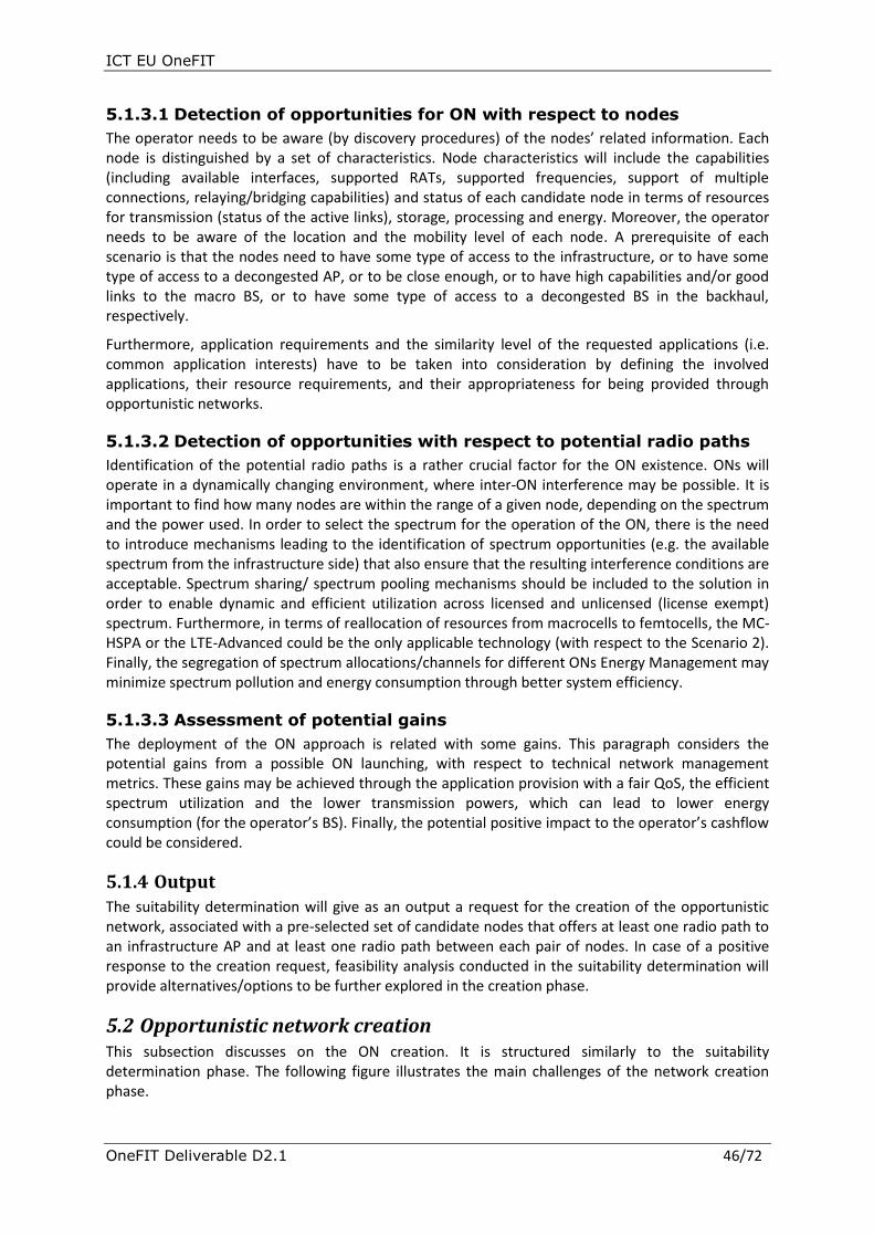
ICT EU OneFIT
OneFIT Deliverable D2.1 46/72
5.1.3.1 Detection of opportunities for ON with respect to nodes
The operator needs to be aware (by discovery procedures) of the nodes’ related information. Each node is distinguished by a set of characteristics. Node characteristics will include the capabilities (including available interfaces, supported RATs, supported frequencies, support of multiple connections, relaying/bridging capabilities) and status of each candidate node in terms of resources for transmission (status of the active links), storage, processing and energy. Moreover, the operator needs to be aware of the location and the mobility level of each node. A prerequisite of each scenario is that the nodes need to have some type of access to the infrastructure, or to have some type of access to a decongested AP, or to be close enough, or to have high capabilities and/or good links to the macro BS, or to have some type of access to a decongested BS in the backhaul, respectively.
Furthermore, application requirements and the similarity level of the requested applications (i.e. common application interests) have to be taken into consideration by defining the involved applications, their resource requirements, and their appropriateness for being provided through opportunistic networks.
5.1.3.2 Detection of opportunities with respect to potential radio paths
Identification of the potential radio paths is a rather crucial factor for the ON existence. ONs will operate in a dynamically changing environment, where inter-ON interference may be possible. It is important to find how many nodes are within the range of a given node, depending on the spectrum and the power used. In order to select the spectrum for the operation of the ON, there is the need to introduce mechanisms leading to the identification of spectrum opportunities (e.g. the available spectrum from the infrastructure side) that also ensure that the resulting interference conditions are acceptable. Spectrum sharing/ spectrum pooling mechanisms should be included to the solution in order to enable dynamic and efficient utilization across licensed and unlicensed (license exempt) spectrum. Furthermore, in terms of reallocation of resources from macrocells to femtocells, the MC-HSPA or the LTE-Advanced could be the only applicable technology (with respect to the Scenario 2). Finally, the segregation of spectrum allocations/channels for different ONs Energy Management may minimize spectrum pollution and energy consumption through better system efficiency.
5.1.3.3 Assessment of potential gains
The deployment of the ON approach is related with some gains. This paragraph considers the potential gains from a possible ON launching, with respect to technical network management metrics. These gains may be achieved through the application provision with a fair QoS, the efficient spectrum utilization and the lower transmission powers, which can lead to lower energy consumption (for the operator’s BS). Finally, the potential positive impact to the operator’s cashflow could be considered.
5.1.4 Output The suitability determination will give as an output a request for the creation of the opportunistic network, associated with a pre-selected set of candidate nodes that offers at least one radio path to an infrastructure AP and at least one radio path between each pair of nodes. In case of a positive response to the creation request, feasibility analysis conducted in the suitability determination will provide alternatives/options to be further explored in the creation phase.
5.2 Opportunistic network creation This subsection discusses on the ON creation. It is structured similarly to the suitability determination phase. The following figure illustrates the main challenges of the network creation phase.
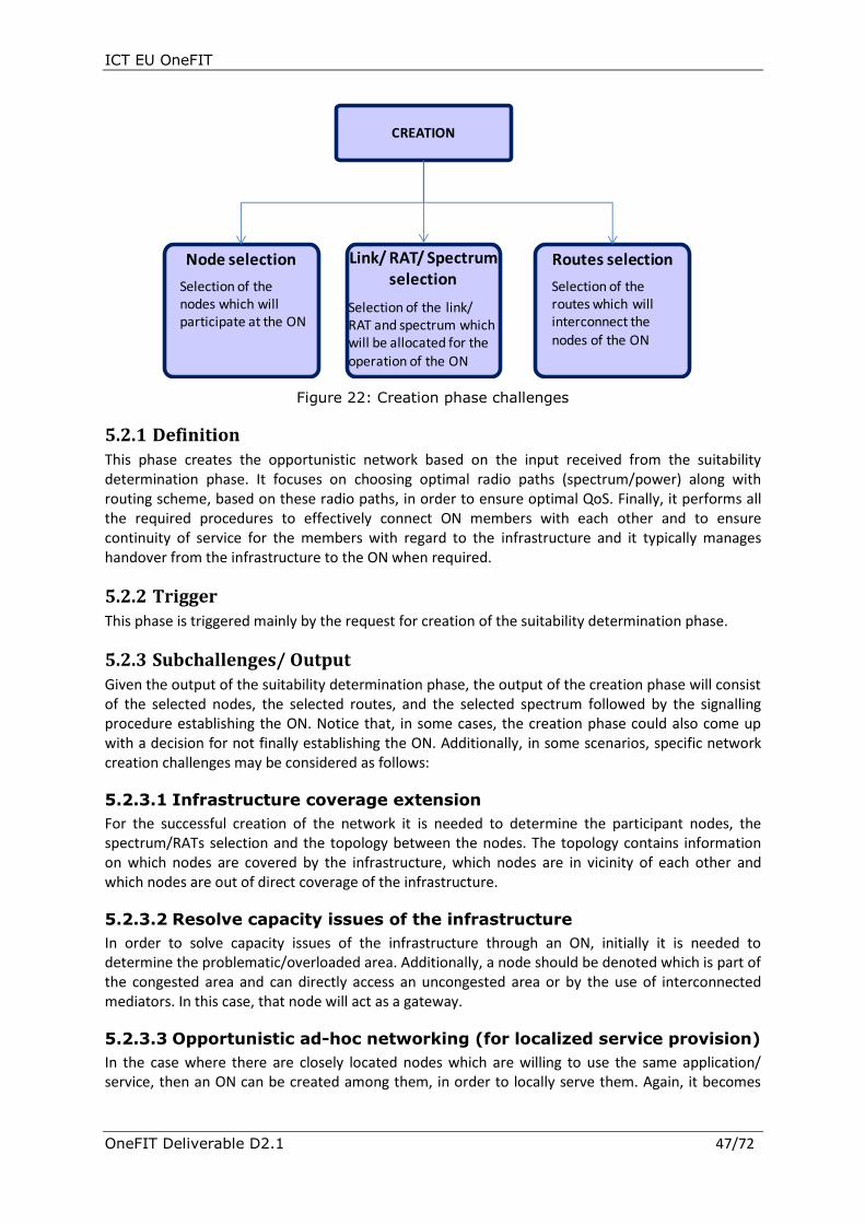
ICT EU OneFIT
OneFIT Deliverable D2.1 47/72
CREATION
Node selection Link/ RAT/ Spectrum selection
Routes selection
Selection of the nodes which will participate at the ON
Selection of the link/ RAT and spectrum which will be allocated for the
operation of the ON
Selection of the routes which will interconnect the nodes of the ON
Figure 22: Creation phase challenges
5.2.1 Definition
This phase creates the opportunistic network based on the input received from the suitability determination phase. It focuses on choosing optimal radio paths (spectrum/power) along with routing scheme, based on these radio paths, in order to ensure optimal QoS. Finally, it performs all the required procedures to effectively connect ON members with each other and to ensure continuity of service for the members with regard to the infrastructure and it typically manages handover from the infrastructure to the ON when required.
5.2.2 Trigger
This phase is triggered mainly by the request for creation of the suitability determination phase.
5.2.3 Subchallenges/ Output
Given the output of the suitability determination phase, the output of the creation phase will consist of the selected nodes, the selected routes, and the selected spectrum followed by the signalling procedure establishing the ON. Notice that, in some cases, the creation phase could also come up with a decision for not finally establishing the ON. Additionally, in some scenarios, specific network creation challenges may be considered as follows:
5.2.3.1 Infrastructure coverage extension
For the successful creation of the network it is needed to determine the participant nodes, the spectrum/RATs selection and the topology between the nodes. The topology contains information on which nodes are covered by the infrastructure, which nodes are in vicinity of each other and which nodes are out of direct coverage of the infrastructure.
5.2.3.2 Resolve capacity issues of the infrastructure
In order to solve capacity issues of the infrastructure through an ON, initially it is needed to determine the problematic/overloaded area. Additionally, a node should be denoted which is part of the congested area and can directly access an uncongested area or by the use of interconnected mediators. In this case, that node will act as a gateway.
5.2.3.3 Opportunistic ad-hoc networking (for localized service provision)
In the case where there are closely located nodes which are willing to use the same application/ service, then an ON can be created among them, in order to locally serve them. Again, it becomes

ICT EU OneFIT
OneFIT Deliverable D2.1 48/72
clear that the selection of the participant nodes, the spectrum availability and the interconnection of nodes is rather important in order to successfully create the ON.
5.2.3.4 Opportunistic traffic aggregation in the access network
In order to enable a better utilization of the available radio resources through an ON, an aggregator node(s) which will act as a gateway and provide the interconnection between the macro BS and the ON via a dedicated channel needs to be identified. The gateway node(s) must have strong resources and high quality of link (or links, in case of multiple interfaces) with the macro BS. Finally, it needs to be located in a good position/location regarding the macro BS (i.e. low level of interference, inbound the service area of the macro BS etc.) in order to be able to establish and maintain the connection.
5.2.3.5 Opportunistic resource aggregation in the backhaul
Finally, the ON may be created in order to handle resource aggregation in the backhaul network, in cases when the backhaul experiences overloading situations. Thus, a multiple-BS opportunistic network is created with respect to the above considerations.
5.3 Opportunistic network maintenance The ON will have to be dynamic during all its operational life-time. In order to achieve this, once the creation phase has been completed, the maintenance phase has to be initiated.
In general, the maintenance phase will have to:
monitor nodes, spectrum, policies, QoS and
decide whether it is suitable to proceed to a merge/split of an ON, or to a reconfiguration of an ON.
5.3.1 Definition
The maintenance phase is responsible for applying, at the right time, all the appropriate changes at the ON configuration, in order to maintain the efficient operation of the ON and to provide adaptability to changing environmental conditions.
The figure that follows explains the main objectives of the maintenance phase.
MAINTENANCE
Monitor Reconfiguration Decisions• Application QoS
• Mobility• Spectrum condition
changes• Policy changes
• Modification of an ON • Merge/Split of ONs (governed by the
operator)
Figure 23: Maintenance phase main objectives
5.3.2 Trigger
The trigger to the maintenance phase is the successful completion of the creation phase.

ICT EU OneFIT
OneFIT Deliverable D2.1 49/72
5.3.3 Subchallenges/ Output This phase key subchallenges are the monitoring of the ON environment and the dynamic implementation of all the appropriate reconfigurations at the ON.
5.3.3.1 Monitoring
One basic process of the maintenance phase is that of acquiring information from ON nodes about their experiencing application QoS, mobility, spectrum condition changes and policy changes. We need to have information about the providing QoS for services running on the nodes which request the access via another node, to be sure that the application prosumer nodes are successfully served. Furthermore, information is needed regarding the providing QoS for services already running on the relaying/forwarding nodes, in order to assure that the QoS of those nodes hasn’t been influenced by the additional relaying/forwarding functionalities.
Moreover, it is essential to monitor the mobility level of each node, in order to have information regarding the movement patterns and speed of nodes in the ON. These movement patterns will help to define which nodes are going to leave the ON. Moreover, spectrum condition and policy changes have to be monitored frequently in order to be aware of the spectrum availability and the altered policies so that the respective changes are made.
This monitoring information will be used to define a fair level of the ON operation. This involves a variety of mechanisms and strategies whose target is to ensure the preservation of application provisioning and that the established QoS criteria are met by properly handling interference. Also by this information we can ensure that ON users have a fair level of throughput which means that the communication links operate normally. Additionally, through this information the relaying amount of different nodes can be checked in order to maintain the effectiveness of the ON.
Finally, monitoring is also needed, in order to define when the reconfiguration decision will take place.
5.3.3.2 Reconfiguration decisions
This section contains the reconfiguration decisions that can be made during the maintenance phase. These decisions can be made because of alterations in ON nodes’ status, radio paths conditions or in policies.
5.3.3.2.1 Reconfiguration of an ON
The reconfiguration process, which is part of the ON maintenance phase, is responsible for applying all the appropriate changes at the ON configuration in order to achieve the most efficient operation of the ON.
The reconfiguration process has to act in cases where the ON nodes status has been altered, or nodes are joining or disconnect from the ON (e.g. when a node becomes idle while it was active, or the opposite, or when a node which has relaying/forwarding functionalities stops operating). In cases like this, the reconfiguration process has to be supported by dynamic discovery procedures leading to the dynamic identification of nodes which start (just joined the ON or were already participants) or stop (disconnected from the ON or just became unavailable) requiring services, so that the reconfiguration process reserves or releases resources. The infrastructure shall also be able to advertise the presence of potential available relaying nodes, or the presence of a nearby established ON.
Moreover, a more specific case that the reconfiguration process has to be activated is when there is a change at the gateway of the ON. This could happen if the used gateway node becomes unavailable or when the used gateway becomes inappropriate (e.g. moved away from the served nodes). In cases like this the reconfiguration process has to select a new gateway and also to initialize rerouting algorithms in order to dynamically derive the proper routes across the nodes

ICT EU OneFIT
OneFIT Deliverable D2.1 50/72
forming the ON taking into consideration the interference that the different nodes and routes may cause. In advance the reconfiguration has to provide seamless handovers, within opportunistic network, between the end nodes and the new gateways.
Another case where the reconfiguration process has to engage, is when there are changes at the available spectrum. For example, when a frequency band is released by another network then the reconfiguration process has to initialize mechanisms leading to the dynamic identification of spectrum opportunities that also ensure that the resulting interference conditions are acceptable. Furthermore, reconfiguration is responsible for enabling peaceful cohabitation of composite/ heterogeneous radio systems through sensing and coordinated adaptation via an intelligent overlay protocol. By this functionality ON becomes more scalable as it can adapt to different operational environments.
Another use case of the reconfiguration process is when there is a change in policies by the network operator, which affects ON’s users. In cases like this, there has to be an enforcement of the new policy at the nodes which are affected; by changing whatever the policy indicates.
Furthermore, the reconfiguration process has to be enhanced with cognitive engine/learning loop which includes networking routing/management of network elements or other cognitive radio units. In addition, these elements or units have to be enhanced with some basic cognitive attributes such as adaptation loop which has been expanded to include contextual parameters and to have memory for learning from past parameters. Also those learning/cognition attributes have to be controlled by policies and be technology independent. Finally, hierarchical policies/learning distributed between device and network edges will exist in order to enable management of segmented data base, content video library or files across ON and enable collaborative sensing and deep learning.
5.3.3.2.2 Merging/Splitting of ONs
Another reconfiguration decision that may be made during the maintenance phase is the merging or splitting of ONs. Merging/splitting decisions have to be in any case ensured that they will be operator governed, thus ONs will not be able to decide autonomously for its existence. A more detailed description of this procedure follows.
The maintenance of an ON might be in some cases a difficult task because of the fact that there might not be enough resources to support the ON operation or the ON itself may be “weak” (i.e. the ON’s radio environment maybe suffers from interference so the radio paths are not stable, the supporter nodes cannot support the requested load, etc). But there might be other ONs nearby which are more robust and can serve more users than those who are already serving. In cases like this, a solution would be the weak ON to be merged with a neighbouring/adjacent and more powerful ON which is capable to support the weak ON’s users.
Otherwise, if there is no other stronger ON nearby, a possible solution would be the weak ON to be split in smaller ONs in order to maintain the provision of services to the nodes which were already served by the primary ON.
The challenges which derive from the merging/splitting procedure can be listed as follows:
The network operator has to be aware of the ONs which operate in the same area, each ON current status, which means to have information about its serving users and each user condition (e.g. resources, location, provided QoS), and also to be aware whether or not an ON is in a critical situation (which means that is difficult to continue operating).
If an ON splitting is going to take place, then a suitability determination, followed by a creation process, which has to be initialized.
The network operator should arrange the handover of the weak ON’s users to the better ON or to the new born ONs, in order to finish the merging/splitting procedure.
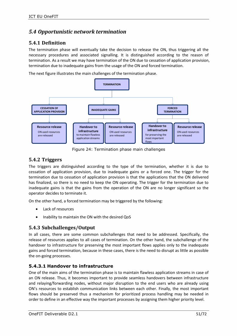
ICT EU OneFIT
OneFIT Deliverable D2.1 51/72
5.4 Opportunistic network termination
5.4.1 Definition The termination phase will eventually take the decision to release the ON, thus triggering all the necessary procedures and associated signalling. It is distinguished according to the reason of termination. As a result we may have termination of the ON due to cessation of application provision, termination due to inadequate gains from the usage of the ON and forced termination.
The next figure illustrates the main challenges of the termination phase.
CESSATION OF APPLICATION PROVISION
INADEQUATE GAINS
TERMINATION
Resource release Resource release
ON used resources are released
ON used resources are released
Resource release
ON used resources are released
Handover to infrastructure
for preserving the most important flows
Handover to infrastructure
to maintain flawless application streams
FORCED TERMINATION
Figure 24: Termination phase main challenges
5.4.2 Triggers
The triggers are distinguished according to the type of the termination, whether it is due to cessation of application provision, due to inadequate gains or a forced one. The trigger for the termination due to cessation of application provision is that the applications that the ON delivered has finalized, so there is no need to keep the ON operating. The trigger for the termination due to inadequate gains is that the gains from the operation of the ON are no longer significant so the operator decides to terminate it.
On the other hand, a forced termination may be triggered by the following:
Lack of resources
Inability to maintain the ON with the desired QoS
5.4.3 Subchallenges/Output
In all cases, there are some common subchallenges that need to be addressed. Specifically, the release of resources applies to all cases of termination. On the other hand, the subchallenge of the handover to infrastructure for preserving the most important flows applies only to the inadequate gains and forced termination, because in these cases, there is the need to disrupt as little as possible the on-going processes.
5.4.3.1 Handover to infrastructure
One of the main aims of the termination phase is to maintain flawless application streams in case of an ON release. Thus, it becomes important to provide seamless handovers between infrastructure and relaying/forwarding nodes, without major disruption to the end users who are already using ON’s resources to establish communication links between each other. Finally, the most important flows should be preserved thus a mechanism for prioritized process handling may be needed in order to define in an effective way the important processes by assigning them higher priority level.

ICT EU OneFIT
OneFIT Deliverable D2.1 52/72
5.4.3.2 Resource release
When an ON termination procedure takes place, then the ON used resources are released. The released opportunistic network resources can then be allocated to another ON, in order to provide an extension to the infrastructure or to solve congestion issues, etc.
5.5 Security and trust Security and trust is presented separately because it takes place during all phases. A first security principle is that any underlying infrastructure is supposed to be insecure. It could be composed by a set of heterogeneous transmission media, each one with different security services or features. Such claim forces us to think about the transmission medium as an open broadcasting medium that any device could listen, read and modify the contents of the communication.
In general, a service might be analysed, as being composed by layers or blocks. The layers’ analysis may be the following:
Application layer, developed by the service developer. This one contains the real application that gives value to the ON and makes use of it.
API layer, developed by the ON service provider. This second layer provides services to the application layer: local resources allocation, registration, sending messages, setting up a virtual circuit, etc.
Protocol layer, developed by the ON service provider. This contains the definitions of the messages the ON nodes should understand when they are received and use for sending messages.
Transmission medium specific, e.g. Bluetooth, Wi-Fi or 3G layers. This is a different layer depending on which of the supported transmission media are used. This layer provides different services depending on the transmission medium selected.
Specifically, local resources and private data stored in the terminal should be protected, thus the access to local resources should be controlled and limited. The access to private data stored in the terminal should be protected and audited. Moreover, the device identity has to be protected by hiding its real identification and by avoiding associating a user’s identity and his device’s identity. This association could mean a threat to that user’s physical integrity (i.e. especially related to terrorism, and interest for public figures). The avoidance of the ON applications to select/ reject a device is also important, as the decision upon the path and the devices involved in the communication falls within the responsibility of the ON algorithms. If the applications were allowed to do this task, the ON performance would be cut down. Furthermore, the protection of the privacy of the data while traversing the ON is crucial as some pieces of data should be protected against revealing by intermediate devices. Security of user credentials via authentication, authorization and accounting data is a prerequisite. Content security with respect to privacy issues, trust relationships (i.e. determination/discovery of trust relationship between nodes and access networks or nodes and relaying/forwarding nodes), ownership of data and content encryption is required as well.
Moreover, the applications that use the ON will be controlled as some applications behave abnormally, either because of damages caused to the networks, or due to users’ behaviour. The applications that are created with bad aims would not pass a certification process. The applications that behave in a proper manner (and pass the certification process) but afterwards users may complain about a bad behaviour should be prohibited as well.
Another challenge lies on the fact that messages of the ON protocol should be kept off modification by any unauthorized entity. This happens, in order to avoid attacks against ON protocol and to detect those messages that had been modified by an unauthorized entity, as well as to avoid access

ICT EU OneFIT
OneFIT Deliverable D2.1 53/72
to unauthorized resources by unauthorized devices that could use message modification as a key to access resources from the ON.
The ON has to prevent incidents of identity disguise. This means that a user with bad intentions will not be able to use another’s identity to act in his name or to access resources at no cost, or to access resources the other user does. On the other hand, a certain amount of anonymity to users, using an alias in some ON services or applications could be allowed.
The maintenance of a minimum level of availability is important as an ON will be composed of a number of nearby devices. As a result, ON should have a level of availability that ensures the continuity of the service, in case one of the nodes fells down (go out of the reachability zone of other device).
ICT EU OneFIT
OneFIT Deliverable D2.1 54/72
6. System requirements This section describes the system requirements for the OneFIT system. These system requirements will guide the further work in the OneFIT project, including the specification of the architecture, the control channels for the cooperation of the cognitive management system (C4MS) protocol design, the algorithms as well as the validation activities.
6.1 General requirements
Requirement G1: Communication with the infrastructure
The OneFIT system shall allow terminals to directly or indirectly communicate with the infrastructure.
Requirement G2: Communication between terminals
The OneFIT system shall allow terminals to directly or indirectly communicate with each other.
Requirement G3: Versatile spectrum use
The OneFIT system shall support the operation of ON using spectrum with any regulatory regime, licensed, shared/unlicensed or opportunistic.
Requirement G4: Versatile RAT/RAN use
The OneFIT system shall be able to operate opportunistic networks making use of different kinds of radio access technologies.
Requirement G5: Mobility
The OneFIT system shall support service continuity during the full lifecycle of the ON. This means that dependent on the specific service cases, seamless mobility or lossless mobility is supported from the Infrastructure to the ON, within an ON as well as from the ONs to the infrastructure.
Requirement G6: Relaying
Relaying shall be supported. The relaying can be provided by infrastructure nodes or by user terminals. The relaying mechanism shall provide forwarding capabilities for user data as well as for control signalling. The OneFIT system shall support heterogeneous as well as homogeneous relaying.
Requirement G7: Creation of opportunistic networks
The OneFIT system shall support mechanisms that achieve on-the-fly negotiations and agreements for the creation of opportunistic networks.
The nodes of the ON can be terminal-type or infrastructure-type.
Requirement G8: Opportunistic Networks controllable by single operator
The OneFIT system shall support the operation of Opportunistic Networks under the control of and within resources of a single operator, with all members of the ON being direct subscriber of this operator or under a “roaming agreement3” with the latter.
Requirement G9: Preservation of legacy RAN operation
3 The requirement to support roaming subscribers as ON members may lead to an over-
complexity compared to the benefit – analysis of “roaming scenarios” is needed

ICT EU OneFIT
OneFIT Deliverable D2.1 55/72
The operation of the OneFIT system and opportunistic networks shall not affect the efficiency and performance of the “anchor” network, in terms of mobility (idle and connected), spectrum use, signalling load, security/privacy, charging/billing.
Requirement G10: Compatibility with legacy RAN deployments
The operation of the OneFIT system and opportunistic networks shall be compatible with legacy and foreseeable RAN deployments/planning techniques, e.g. overlays of macro/femto/relay.
Requirement G11: Resource efficiency
The OneFIT system shall fulfil the service requirements in a resource efficient manner.
6.2 User and service related requirements Requirement U1: Hide complexity from the end user
The OneFIT system shall hide the complexity from the end user.
User intervention shall be avoided when creating an opportunistic network.
Requirement U2: User’s service perception
Creation, reconfiguration and termination of an opportunistic network should not affect end user’s service perception.
Requirement U3: Availability of ON-related information to the service layer
In order to provide ON-specific services, relevant ON-related information should be propagated to the service layer, such as:
The fact that the terminal is connected to an ON, a sort of “In ON flag”
An identification of the ON, i.e. what ON(s) the device is connected to
An identification of the devices connected to the ON at a given time (or at least a mechanism to discover them)
6.3 Opportunistic network management requirements
Requirement M1: Identification of the need for an opportunistic network
It shall be possible to identify the need of an opportunistic network. This can e.g. be based on application-level information.
Requirement M2: Suitability determination
It shall be possible to determinate the suitability of opportunistic networks.
Requirement M3: Creation of opportunistic networks
The OneFIT system shall support mechanisms that achieve on-the-fly negotiations and agreements for the creation of opportunistic networks.
Requirement M4: Connection set-up
A terminal in an ON shall be able to set-up a connection with the infrastructure.
The infrastructure shall be able to trigger a terminal in an ON to set-up a connection.
Requirement M5: Maintenance of opportunistic networks
The OneFIT system shall support mechanisms for the maintenance and reconfiguration of opportunistic networks.

ICT EU OneFIT
OneFIT Deliverable D2.1 56/72
The OneFIT system shall enable nodes to join and disconnect from the opportunistic networks.
It shall be possible for the OneFIT system to select/appoint one of the terminals in an ON as a relaying node.
It shall be possible for the OneFIT system to change the relaying node (i.e. pick a new one) during operation.
Requirement M6: Release of opportunistic networks
The OneFIT system shall support mechanisms for the release of opportunistic networks.
Requirement M7: Coordination of opportunistic networks with the infrastructure
The opportunistic network shall be able to coordinate its functions with the infrastructure network(s).
Requirement M8: Opportunistic network identification
It shall be possible to uniquely identify an ON.
It should be possible to assign a human readable name to an ON.
Further on, each node of an ON shall have a unique identity/address within the ON.
Requirement M9: Maximum size of an opportunistic network
The OneFIT system shall be able to control the maximum size of an opportunistic network.
Requirement M10: Coexistence of opportunistic networks
The OneFIT system shall support the coexistence of opportunistic networks. Several opportunistic networks may coexist in the same geographical area.
Requirement M11: Assignment of bandwidth
It shall be possible to assign bandwidth for traffic to/from ON nodes dynamically.
6.3.1 Related algorithms requirements
Requirement A1: Context awareness
The system shall be able to obtain the capabilities and status of the network and the involved nodes.
The system shall be able to obtain QoS requirements for applications/services supported in an ON.
The system shall be able to estimate the radio channel conditions between ON nodes.
It shall be possible to obtain information about the geo-location of the nodes.
The system shall be able to identify the spectrum occupancy related to a given time and place.
It shall be possible to predict the occupancy in all the bands considered by the supporting network for creation and/or usage of the ON.
The system shall be able to monitor resource usage (including current traffic flows) and QoS metrics of an ON.
It shall be possible to predict the mobility of the nodes in the ON (e.g. is this candidate node expected to remain in the vicinity of the ON for a sufficient time? This information is also

ICT EU OneFIT
OneFIT Deliverable D2.1 57/72
needed to prepare for re-allocation/re-routing if/when a node will not be suitable any more).
Requirement A2: Decision making
The system shall be able to make decisions for the management of the opportunistic networks, including decisions for the creation, reconfiguration and termination of an ON (see also requirements M1 – M9 above). This includes:
The system shall be able to make decisions on which candidate nodes to participate in an ON.
The system shall be able to make decisions on the more appropriate spectrum bands and other radio transmission parameters for an ON.
The system shall be able to make decisions to control the QoS for applications/services supported in an ON.
Requirement A3: Routing
Optimized routing shall be applied after consideration of latency, power consumption and risk (see prediction of mobility)
Requirement A4: ON Advertisement:
The OneFIT system shall be able to advertise the presence of a potential relaying node at a given location.
The OneFIT system shall be able to advertise the presence of an established ON at a given location.
The relaying node shall be able to advertise its ON capabilities via the ON
6.4 Protocol requirements
Requirement P1: Protocol usage
A protocol or a set of protocols shall be used for the communication between different nodes.
The protocol(s) shall enable communication between nodes belonging to a single opportunistic network
The protocol(s) shall enable communication between nodes belonging to different opportunistic networks
Requirement P2: Broadcast/Multicast
The protocol(s) shall support mechanisms to transmit information to several nodes, e.g. via broadcast or multicast mechanisms.
Requirement P3: Unicast/Dedicated addressing
The protocol(s) shall support mechanisms to transmit information to a single node identified via an address, e.g. via unicast or dedicated mechanisms.
Such a peer-to-peer connectivity shall be supported also in cases without the existence of a direct link between the two communicating nodes.
Requirement P4: Secure as well as unsecure communication
The protocol shall allow for unsecured as well as secure data transmission, dependent on the confidentiality of the data.

ICT EU OneFIT
OneFIT Deliverable D2.1 58/72
Requirement P5: Protocol efficiency
Scalable: The protocol shall be capable of supporting several simultaneous requests.
Radio technology independence: The protocol should be usable for different types of radio access technologies and should therefore be radio independent. However, radio technology intrinsic mechanism e.g. to broadcast certain information may also be supported.
The information shall be encoded compactly.
Reuse of existing protocols should be considered. Open protocols are preferred.
The amount of signalling shall be minimized.
The protocol shall allow reliable transfer of information
The latency shall be compatible with targeted applications’ requirements for QoS, even if several hops are involved.
6.5 Security requirements
Requirement S1: Security
The OneFIT system shall allow that the communication can take place in a secure manner. It is also very important to establish a trust relationship between the various parts of the opportunistic network.
Mutual authentication shall be used between terminals in the ON
Mutual authentication shall be used between relaying nodes and the infrastructure
Mutual authentication shall be used between terminal in the ON and the infrastructure (via the relaying node)
Requirement S2: Accountability, charging and billing
The OneFIT system shall provide means for the nodes to conduct authorization and authentication for charging and billing.
The OneFIT system must also be able to interact with legacy accounting systems.
The OneFIT system shall support rewarding systems. The implementation of such a rewarding system may differ depending on the scenario (direct bill discounts, 'karma' points, etc.)
Requirement S3: Protection of user identity
The real user of an ON service/application must be identified and authenticated.
The identity shown to other users could be the real identity or an alias if the user chooses to do so.
The user may in any moment switch his identity from real or an alias or assign default identity for each ON application or service.
Requirement S4: Protection of device identity
Each device should have a unique device identity. The aim of this identity is to identify the device uniquely to the infrastructure. Temporary identities should be used to avoid associations of a device identity with the user’s identity.
Device identities should be anonymized to ON applications by the ON API. The ON API should maintain a table to translate anonymized identities to temporary identities and vice versa.

ICT EU OneFIT
OneFIT Deliverable D2.1 59/72
Requirement S5: Authorization of applications
The ON applications should contain a list of permissions to use some ON services.
The ON should provide control mechanisms to decide which applications are or are not allowed to use the ON services.
The ON application’s binary code should contain integrity controls allowing the ON API to know about the identity of the application.
The ON should be able to cancel a yet-provisioned ON application/service, e.g. in cases where an abnormal or dangerous behaviour has been detected.
Requirement S6: Protection of local private data (e.g. inside the terminal)
Local resources and private data stored in the terminal should be protected.
The ON applications should run with a lower level of privileges in the terminal avoiding that an insecure application could threat private data of the user or abuse resources/capabilities of the terminal.
The ON API or a wrapper application should run with higher privileges in order to access local resources and/or private data. Access to private data should be auditable.
Requirement S6: Protection of private data while traversing the network
The ON layer (API) should be the interface between application layer and the infrastructure. This layer must provide functionalities to cipher those data packets as instructed by the application level. The application would only concern about which of the data elements must be protected, but not how they are protected or which of the algorithms has been used to do that.
Every message of the ON protocol should include an integrity check signature. This signature should be based on a key and the contents of the message, and the key should be known only by those devices involved in the communication (sender, receiver and, probably, intermediates of the communication).
The integrity mechanism used should be such that a device couldn’t be a target of a Denial of Service attack. Calculation of such integrity signatures should involve an appropriate amount of processing power (limited as it is in mobile devices).
Requirement S7: Approval
It shall not be possible to establish an ON without approval of the RANOp. Such an approval may be included in the operator’s policies or in the user profile settings.
It shall not be possible to establish an ON without the approval of the user of the relaying node. Such an approval may be included in general user settings or may be made per call/session.
The user of the relaying node should be informed if their device is used as a relaying node.

ICT EU OneFIT
OneFIT Deliverable D2.1 60/72
7. State of the art This chapter reviews the state of the art related to the scenarios identified in Chapter 4.
7.1 Coverage extension The standard solution in mobile networks is that a user has a direct connection to the infrastructure without any relaying/forwarding nodes in-between. The following section reviews different existing solutions for the network coverage extension (it is worth to note that relaying/forwarding is present in most of the OneFIT scenarios and it is essential not only for the coverage extension but also for capacity extension and for enabling traffic aggregation).
One of the solutions on the market is a “tethering-functionality” where a mobile device (e.g. a smartphone), is used like a modem to provide internet access for another device, typically connected short range over Bluetooth or a universal serial bus (USB) cable. In contrast to this solution, where the owner of the device in the middle has to pay for the service, OneFIT targets a solution in which the end user is charged for the service and the service is provided also over longer ranges.
Another solution is based on the concept of fixed relays and it is part of 3GPP Rel-10 for LTE-Advanced. The Relay Node (RN) is served by a Donor Cell (DC), and the cells controlled by a RN (serving the user equipment) appear as separate cells distinct from the DC, i.e. they have their own physical cell identification, own synchronization channels, reference symbols, etc. The user equipment receives scheduling information and Hybrid Automatic Repeat Request (HARQ) feedback directly from the RN and sends its uplink control channel information (SR/CQI/ACK) directly to the RN. The RN as described in [5] is a fixed node belonging to the operator’s network, but like shown in the scenario 1 (see Figure 2), it can also be envisaged to use a mobile terminal as relay node. More details on RN in 3GPP (including a comparison of various architecture options) can be found in 3GPP TR 36.806 [27].
Another relaying solution is based on the 3GPP vision of Evolved Packet Core (EPC) which enables interoperation of non-3GPP technologies with legacy 3GPP technologies. In this solution multi-mode mobile terminals can be treated as non-3GPP Internet Protocol (IP) network access points and thus can be used as relays/forwarders. Figure 25 shows the path of the data forwarded/relayed by the multi-mode terminal. The data of the served terminal shares the path with the data of the relaying/forwarding terminal up to the Packet Data Network (PDN) Gateway of the forwarding/relaying terminal. From that point, the data of the served terminal follows the path established during the initial attachment procedure for an untrusted/trusted non-3GPP IP access connection (more details can be found in [11]).
Figure 25: Simplified vision of data relaying based on the 3GPP vision of EPC
Although the solution enables relaying with the seamless Vertical Handover (VHO) and thus in theory could also support the service of data relaying/forwarding in the framework of opportunistic networks, several shortcomings which do not allow its full application can be identified:

ICT EU OneFIT
OneFIT Deliverable D2.1 61/72
Lack of mechanisms for creation and maintenance of opportunistic networks;
lack of procedures for reservation of resources and maintaining the QoS for services running on the UE requesting access to the network via another UE;
lack of procedures to guarantee QoS for services running on UE acting as a forwarder/relay;
lack of procedures, which would enable the determination of the identity of the forwarder/relay which is necessary to implement user rewarding system.
The Unlicensed Mobile Access (UMA) enables GSM, GPRS/EDGE, as well as UMTS/HSPA services, to be transported over WLAN or similar technologies in license free ISM-bands. In 3GPP, this solution, which requires Wi-Fi/UMA enabled handsets, is called Generic Access Network (GAN) [6]. UMA/GAN supports scenarios as shown in Figure 4. However, Wi-Fi/UMA enabled handsets are needed for this solution.
Home Node Bs (femto BS) are also state of the art [1][4]. OneFIT targets solutions where not only a limited number of persons (e.g. the subscriber who has the Femto Base Station in his home or a Closed User Group), but also other users can use the Home Node-B by joining the opportunistic network.
7.2 Congestion resolution and congestion preventing in Radio Access Networks
The following sub-section describes the existing solutions for preventing and resolving congestions in accessing the infrastructure network. The section describes state-of-the-art specific to the problems introduced in scenario 2.
Within current 3GPP networks, load balancing mechanisms try to avoid that a cell is going into a congested situation. Load balancing algorithms may result in handover or cell reselection decisions with the purpose of redistributing traffic from highly loaded cells to underutilized cells [5]. Such a handover can be an intra-technology handover or an inter-technology handover [22][24]. The load of the network is also considered in the case of a 3GPP system to WLAN interworking, e.g. when a multi-mode terminal can use both 3GPP systems and WLAN selection [23].
Further on, 3GPP considers the re-parameterization of base stations with self-x algorithms for adapting handover and/or reselection configuration parameters to improve the load balancing [5]. However, those approaches build on RATs that have been defined in an integrated framework, such as GSM, UMTS, HSPA, LTE, etc.
The current schemes for coordination between macrocell overlay and underlying femtocells have some level of dynamicity [19] and are based on local measurements and signalling through backhaul connection. The femtocell is managed remotely by a Home Node-B Management System deployed in the operator Operations, Administration, and Maintenance (OAM) system. The architecture is described in [21]. The interference scenarios between macrocell and femtocell are described in [20]. A femtocell can operate in a dedicated channel or in a co-channel (a channel shared with a macro-cell network) or in a partial co-channel (the femtocell uses only a subset of the macrocell band). Six interference scenarios have been identified: UE attached to femtocell interferes with macrocell uplink; femtocell interferes with macrocell downlink; UE attached to macrocell interferes with femtocell uplink; macrocell interferes with femtocell downlink; UE attached to femtocell interferes with (another) femtocell uplink; femtocell interferes with (another) femtocell downlink.
The solution proposed in OneFIT will allow to optimize the settings (radio resource and power allocation, but also possibly other logic parameters such as Closed User Group (CSG) support) of any underlying femtocell in coordination with the macro overlay, at any time and to address any change in the users’ population. The ON solution does not make use of backhaul resources and rather makes use of available radio resources.

ICT EU OneFIT
OneFIT Deliverable D2.1 62/72
7.3 Infrastructure supported ad-hoc networking An intrinsic characteristic of current infrastructure-based network technologies is the fact that communications between mobile/portable devices are always conducted through a BS or an AP, even when these devices are close to each other and direct communications would be possible. This is the case in current cellular technologies where mobile network operators have full control of any traffic exchanged over its licensed spectrum assets but also in the case of widely used infrastructure IEEE 802.11 local area networks operating in license-exempt bands where stations (STAs) cannot directly communicate with each other.
In IEEE 802.11 technologies, the hybrid coordination function (HCF) protocol introduced in [7] defines a mechanism to establish a direct link connection between STAs. The support of direct link connections in IEEE 802.11 is mainly motivated by an improvement in network performance (e.g., reduced delay and higher capacity in the air interface since information should not be sent twice). Before the actual direct link communication between STAs is activated, the direct link connection should be established based on the connectivity information (e.g., geographical locations and range of the STAs that could be eligible for direct link establishment). In any case, the method for obtaining the connectivity information is not specified in [7]. In the case of cellular technologies, no equivalent mode is currently supported. Apart from the technical challenges in doing so in cellular technologies (e.g., interference management), the support of a sort of direct mode able to cope with different OneFIT use cases (e.g. the “Infrastructure offload” and “Opportunistic networks as platforms for location-specific services”) is also conditioned to the existence of appropriate mechanisms in the network allowing the operator to retain the full control of those communications (e.g., support for accounting and charging functionalities within the opportunistic network).
Support for both direct and infrastructure modes constitutes an important characteristic of specialised technologies for professional users such as Terrestrial Trunked Radio (TETRA). In TETRA, a direct operation mode (DMO) is mainly intended to allow terminals to communicate with each other when no infrastructure is available. So, TETRA does not specify any control mechanisms to manage the switching between DMO and infrastructure modes attending to, e.g., network resource efficiency issues as would be the case in the “Infrastructure offload” scenario. In any case, TETRA supports a so-called Managed Direct Mode Operation (M-DMO) [8] by which frequencies used in DMO may be given for use for a period of time from the infrastructure. Hence, under M-DMO, frequency channels used for direct mode communications need to be first authorised by the infrastructure. The main objective of this is to constrain the transmission such that TETRA terminals will not transmit in a geographical area in which they are not authorised to transmit. The M-DMO mode constitutes a very simple realisation of the managed ad-hoc communications concept envisioned in OneFIT.
Even though there are some preliminary advances towards solutions for the “Infrastructure offload” scenario, as it would be the case of direct link support in IEEE 802.11 infrastructure-based networks, key technical challenges remain unsolved, such as the existence of a proper method for obtaining the required information to decide on the suitability to switch from infrastructure to direct links. This fact constitutes one of the elements to be considered within OneFIT technical challenges referred to as “Discovery procedure” and “Candidate node identification”. Furthermore, IEEE 802.11 direct link is conceived under the idea that involved STAs share the same communication channel with the rest of transmissions to/from the AP. In this regard, OneFIT seeks a more ambitious approach where spectrum opportunity detection and selection functionalities can improve communications efficiency by using the most appropriate frequency bands. As well, QoS control of established connections constitutes a key challenge in this use case. OneFIT solution must be aware of relevant QoS and resource efficiency metrics and, in case of dynamic changing conditions, take adequate actions to keep satisfying them (e.g., a spectrum handover can be triggered when a given band is no longer considered the best choice for a given application).

ICT EU OneFIT
OneFIT Deliverable D2.1 63/72
Efficiently managing ad-hoc networking from the infrastructure side also constitutes a key challenge in OneFIT (e.g. “Infrastructure's governed home networking” use case). As already mentioned in the previous section, M-DMO in TETRA can be thought as a very simple realisation of the infrastructure supported ad-hoc management concept, even though its use is limited to DMO channel authorisation. Regarding the use cases proposed in OneFIT, the variety of technologies in place turns into even more stringent constraints in the conception of a versatile solution able to cope with this heterogeneous environment. Hence, coordination of spectrum utilization and configuration of the key operational parameters of devices using different wireless technologies to communicate with one another is crucial to avoid some channels to become congested (e.g., a Wi-Fi wireless router providing Internet access and a wireless video distribution system are both tuned in overlapping frequency channels). As well, spectrum opportunity detection and selection functionalities should allow application requirements and technology constraints to be considered in the decision-making process. The consideration of potential interference from neighbouring households adds more complexity to this technical challenge. Hence, under such a scenario, OneFIT is expected to cover a holistic approach for spectrum opportunity detection and selection where both licensed and unlicensed spectrum will be considered for home networking communications.
7.4 Traffic aggregation in the radio access network Traffic aggregation has been identified as one of the potential solutions for overcoming the problems related to the underutilization of network resource and signalling overhead to decrease the energy consumption and increase the delivered bandwidth.
The traffic aggregation has been studied in many earlier researches. In order to improve system performance, different types of traffic aggregation schemes have been proposed (e.g. end-to-end aggregation, hop-by-hop aggregation, forced-delay aggregation, accretion aggregation). The majority of the research has been focused however on single-hop (e.g. [30]) or multi-hop (e.g. [29]) IEEE 802.11 networks and sensor networks (e.g. [28]), leaving the cellular networks relatively unexplored (traffic aggregation for the cellular networks has been considered only for the backhaul).
In OneFIT we shall focus on multi-RAT scenarios with the traffic aggregation in the radio access part of cellular networks. Additionally, we shall explore the aspects related to the costs of creation and maintenance of the ad-hoc (opportunistic) networks which are set up to enable traffic aggregation (the previous research focused on homogeneous network scenarios thus such problems were not considered).
7.5 Cooperative Caching Cooperative caching has been identified as one of the possible solutions for enabling more efficient radio resource utilization in the framework of Opportunistic Networks (scenario 4).
Several different cooperative schemes were proposed in the last years. The work related to cooperative caching can be basically subdivided into two categories: cooperative data dissemination and cooperative cache management [15]. Cooperative data dissemination research mainly focuses on efficient protocols for locating the desired data within the network and efficient forwarding of the data to the requesting user (e.g. [18], [12]). Cooperative cache management research focuses on development of protocols for cooperative management of aggregated cache space (e.g. cooperative cache invalidation [16], cooperative cache admission [17], cooperative cache replacement [13]). The most relevant work for OneFIT has been presented by Chow in [14] and [15], in which two cooperative caching schemes, cooperative caching (COCA) and group-based peer-to-peer cooperative caching (GroCOCA), were presented. Both schemes were developed to address a scenario in which users are employed with two radio interfaces using one of them to exchange information with peers and the other one to access the server via a single hop network. In [15],

ICT EU OneFIT
OneFIT Deliverable D2.1 64/72
Chow considers also mobility patterns and data affinity to improve the cache admission and replacement strategies.
Although cooperative caching has been a topic of extensive research for the past several years, it seems that there are still some paths worth exploring. In the case of OneFIT most of them are related with problems specific to cellular networks which, to the best of our knowledge, have never been considered in the context of cooperative caching. These problems could be related with the additional overhead introduced by setting up the connection or with inactivity timers which are used to maintain the active connection for some specific period of time after the data transmission is finished. Besides the issues related to the cellular networks, the costs related to the creation and maintenance of the network for local cache exchange could be included into the evaluation of the cooperative caching for opportunistic networks. Additionally, it is also worth noting that the previous research did not focus on the repercussions of user disconnection in determination of cache admission and cache replacement strategies (user disconnection could lead to the situations in which other users suffer from high ratio of cache misses). This means that the research needs to take the opportunistic network stability into account (period of time when opportunistic network remains unchanged).
7.6 Resource aggregation in the backhaul network Dynamic overlay network creation has been identified as an important aspect for resource aggregation in the backhaul network. The state of the art study showed that there is no prior research looking into this problem in conjunction with the equipment/routing reconfiguration. Some elements of the resource aggregation idea were proposed in the EU-MESH project [26]. EU-MESH (FP7 ICT, project no. 215320) “goal is to develop, evaluate, and trial a system of software modules for building dependable multi-radio multi-channel mesh networks with QoS support that provide ubiquitous and ultra-high speed broadband access”. However it falls short of addressing the resource aggregation by means of dynamic ON creation and equipment reconfiguration. Current mesh networks support creation of several different virtual local area networks (VLANs) on top of existing physical network with different priorities and levels of protection. However routing is done on top of current physical configuration ignoring possibilities of different routing strategies for different virtual networks (i.e. different VLANs can be introduced with different default gateways for sending and receiving data)
7.7 Heterogeneous Radio Access Network management Opportunistic Networks which comprise different wireless systems that operate on unlicensed or licensed bands have been identified as one of the key enablers for improving the overall system performance in OneFIT. However, due to the coexistence issues between the systems, operation of a heterogeneous ON or several homogeneous ONs in one area without the proper management may result in significant degradation of performance (e.g. “Infrastructure's governed home networking” use case).
The main limitation of the state-of-the-art so far is the lack of a configuration framework allowing for a proper management for the coexistence of the diverse wireless systems. At this regard, there are some research efforts focused on the development of an integrated framework where all these physical wireless technologies, together with wired technologies such as power line communications and fibre, could converge. Hence, Omega project [9] is elaborating on a solution framework based on an inter-medium access control (MAC) concept intended to create an Integrated Home Networking technology as a combination of radio, free space optics and wireline technologies within a single “network” solution. Under such an approach, the home itself constitutes the backbone network where all devices are attached. Layer 2 and above are interoperable over all the media (e.g., the home network is a LAN where devices are attached by different transmission media). Another different approach is the development of solutions intended to manage operational settings of

ICT EU OneFIT
OneFIT Deliverable D2.1 65/72
diverse home wireless technologies so that a better overall performance is achieved. Under such a view, Aragorn project [10] considers among its demonstration scenarios the introduction of cognitive radio networks in a home environment to showcase the potential of dynamic spectrum access, cross layer optimization, application adaptation and policy-based prioritization.
The management of heterogeneous RATs which have not been designed in an integrated framework (non-3GPP access networks) has been also a topic of various documents published by the IEEE Standards Coordinating Committee (SCC41) standardization body [25]. In particular, the IEEE 1900.4 standard addresses Network-Device Distributed Decision Making for Optimized Radio Resource Usage in Heterogeneous Wireless Access Networks. However, it does not address the set-up of local, opportunistic networks which needs to be studied and correspondingly addressed (eventually building on IEEE 1900.4) in the framework of OneFIT activities related to the resolution of identified challenges (e.g. congested access to the infrastructure).

ICT EU OneFIT
OneFIT Deliverable D2.1 66/72
8. Envisaged technical solution
8.1 Description of the solution In order to address the identified challenges, there is a need for cognitive management systems combining self-management functionality and knowledge obtained through learning. In particular, two components/ sub-systems are required to be recognised as constituting entities of an ON management system:
CSCI - Cognitive management System for the Coordination of the infrastructure: This entity is in charge of the context acquisition, processing of the same and the determination whether or not right conditions are in place for creating the opportunistic network. In case that the conditions (dictated by the policy engine) are satisfied, the CSCI will come up with an ON blue print design and pass it to the CMON for the execution. As CSCI is responsible for providing the interface between the overall system management system and the CMON it will also assist in the creation, maintenance and release phases. The CSCI should also be in charge of issuing and supervising a request for the forced ON termination.
CMON - Cognitive Management system for the Opportunistic Network: This entity is responsible for executing on the design obtained from the CSCI and then operationally supervising the created ON. This entity should be in charge of the creation, maintenance and release (according to the policies maintained in the CSCI) of the opportunistic network. The contextual and performance parameters collected by the CMON during the life cycle of an ON are used for learning and improvement of its management functions/logic. Equally these data are passed onto the CSCI for improving the governance functions/logic hosted by the CSCI.
The cooperation of the two cognitive management systems will require existence of well defined control messages and protocols/channels for their exchange:
C4MS- Control Channels for the Cooperation of the Cognitive Management Systems
Figure 26: High level hierarchical OneFIT system description
The above figure depicts the protocol stack for the interworking of network nodes participating in a given ON. Different scenarios include the overall composition of ONs. Nevertheless the Scenario 5

ICT EU OneFIT
OneFIT Deliverable D2.1 67/72
can compose an ON exclusively across the infrastructure nodes, therefore a physical connection can be established either over wireless links or wired links.
In terms of functionality implementation the following directions can be identified:
Suitability determination can rely on off-line simulations, conducted a priori. These can investigate the suitability of the opportunistic network approach with respect to specific applications, mobility levels, and interference conditions.
Creation can rely on centralized algorithm (useful for benchmarking) and on distributed ones.
Maintenance can rely on a distributed algorithm (similar to the creation one).
Release can rely on a centralized algorithm.
Emphasis will be placed on solutions compatible with current architectural choices made in 3GPP while taking into account modern IT trends/thinking In this regard, new functional extensions on the user side and the network side need to be implemented in order to address the shortcomings of current 3GPP solutions to fulfil OneFIT system requirements.
8.2 Expected outcome Related to Scenario 1 “Opportunistic coverage extension”, the coverage extension capability of an ON enables devices to communicate over infrastructure networks even if there is no direct connection to an infrastructure network. This is a benefit for the user because he has connectivity also in situations where a direct communication with the infrastructure is not possible. In addition, the operator also benefits because network coverage can be extended without expensive investments in building the infrastructure.
The envisioned solution should bring into Scenario 2 “Opportunistic capacity extension” a number of benefits for network operators, service providers and end users. In particular, users under congestion situation should expect a seamless service provision, with no effects on their quality of experience. For some of them, their data flows will be diverted towards the opportunistic network, but no changes should occur on their previously agreed QoS level. This will allow service providers to offer reliable data-consuming products/applications. New incoming users should be able to connect to their desired service with a sufficient QoS. This will mean a revenue for both network operators and service providers that otherwise would be lost. On the other side, infrastructure nodes should be able to save resources that could be used with new users, enhancing the service level of current ones, or just reducing their energy consumption. When envisioned solution is deployed, we should expect statistical gains in capacity/coverage/load management with a given dual-layer (macro & femto) network, allowing for better return on investment. These statistic gains will be estimated during the initial phase of the study.
The most important benefit expected from developing a solution for the “Infrastructure offload” use case in Scenario 3 “Infrastructure supported opportunistic ad-hoc networking” is the potential reduction of the traffic load (user/control planes) that has to go through the infrastructure. Additionally, the creation of the opportunistic network can also reduce the required transmission powers and ultimately the energy consumption of involved devices. Interference is also reduced resulting in more efficient frequency reuse. As well, the opportunistic network can constitute the enabling platform for location-specific services, as pointed out in the third use case “Opportunistic networks as platforms for location-specific services”. As to coming up with a solution addressing the “Infrastructure's governed home networking” in Scenario 3, the clear benefit is that home networking communications are expected to be managed to operate in a smarter and more autonomous manner. This ultimately contributes to the improvement of end user satisfaction and

ICT EU OneFIT
OneFIT Deliverable D2.1 68/72
enables network operators to position themselves as a sort of “integral connectivity” service providers encompassing both mobility access and home networking communications.
As for Scenario 4 “Opportunistic traffic aggregation in the radio access network”, the expected outcome from the exploitation of an opportunistic network solution includes lower transmission powers in the infrastructure (and therefore, operational expenditures), similar volume of traffic served with less signalling traffic going through the infrastructure, higher utilization of resources (e.g., spectrum, therefore, higher capacity levels) without investing in the infrastructure; this means lower capital expenditures with at least equivalent QoE/QoS levels.
Solutions able to support Scenario 5 “Opportunistic resource aggregation in the backhaul network” should benefit entire value chain including network operators, service providers and end users. Users experiencing slow data service due to the congestion on the backhaul of the connectivity link should expect improved experience as the quality of services is managed by aggregating the backhaul capacity. Data flow will be divided among multiple streams managed by intelligence both on the client side and within the network itself. Between these two pockets of intelligence a control mechanism will reside to create, operate and tear down opportunistic networks when and where needed. Idle pockets of resources within the network will be dynamically aggregated to form an opportunistic overlay network and serve increased number of users with the requested QoS, This should translate into additional revenue for the operators. When the backhaul bandwidth solution is deployed, the overall capacity of the system to serve rich data applications should be increased. The concept will become increasingly attractive as the wireless system solutions become more heterogeneous and incorporate micro/femto underlay based on Wi-Fi and femto cellular AP technologies.
8.3 Validation criteria In general, OneFIT solution shall be validated against State of the Art solutions that address different scenarios introduced in this document. Validation will rely on the following high-level approach:
Individual validation of the functionalities that form part of the envisioned solution, based on simulation.
Integration and testing between components, based on simulation and hardware platform.
Demonstration and experiments based on the hardware platform.
In the following, some further hints specific to some selected scenarios are provided.
With respect to Scenario 1 “Opportunistic coverage extension”, the solution shall be validated against State of the Art solutions on coverage extension, e.g. using fixed relay nodes installed by the operator or 802.11 based ad-hoc/mesh networks. It is assumed that a 3GPP based network using fixed relay nodes provides more stable coverage extension compared to an opportunistic network. However, this comes also along with higher capital expenditure (CAPEX) and operational expenditure (OPEX) for the operator. Further on, it is assumed that a pure 802.11 based ad-hoc/mesh network may have certain security issues compared to a OneFIT solution where guidance and security support can be provided by the infrastructure, e.g. that each user in the opportunistic network can be authenticated.
With respect to Scenario 2 “Opportunistic capacity extension”, two test cases can be validated. In the first one, some selected network nodes are operated on an identical frequency band (e.g., Wi-Fi APs) leading to interference and thus an overall low QoS. The corresponding interference generating devices are identified, reconfigured and included into an opportunistic network applying intelligent routing. In the second one, the validation building on a (near) network overload configuration will be addressed, highlighting how the provision of a basic QoS level can be guaranteed building on opportunistic networks

ICT EU OneFIT
OneFIT Deliverable D2.1 69/72
The analysis to be conducted around Scenario 3 “Infrastructure supported opportunistic ad-hoc networking” needs to consider indicators derived from the impact of the developed solutions over the end users as well as over the efficiency in the utilisation of communications resources. In this respect, a first element to consider is the QoS experience of the users. Relevant indicators to consider from the user perspective would be the user throughput, accounting for the volume of information transmitted per unit of time by a given user, the transmission delay, accounting for the time needed to transmit a certain application message to the other end of the communication, or the service availability, accounting for the probability that the requested service can be set-up at the time when it is needed by the user. As to the efficiency in how the network resources are utilised, a first indicator to consider is the reduction in the traffic volume transmitted through the infrastructure thanks to the use of the opportunistic network. A second aspect to consider is signalling requirements (measured in e.g. bits per second or messages per second) needed by the different processes involved. Also associated with signalling, the time needed to detect the opportunity and set-up the opportunistic network would be useful to assess the performance of the considered solution. Similarly, focusing on the radio resource utilisation, the improvements in spectrum efficiency thanks to the use of the opportunistic network need to be quantified. In the “Infrastructure’s governed home networking” use case, the interesting elements are the reduction in the interference seen by the devices thanks to the coordination carried out by the home networking manager or the spectrum efficiency measured as the total volume of traffic that can be exchanged per unit of bandwidth. Similarly, the required number of spectrum handovers and the associated signalling due to the appearance of a primary user in a frequency being used by the home networking devices can also be an indication to assess the performance of different strategies. In this use case, a benchmark reference for the considered indicators would be the situation when there is no coordination done by the home networking manager in terms of what are the appropriate frequencies to use, etc.
To validate the performance and the benefits of the ON solutions for the Scenario 5 “Opportunistic resource aggregation in the backhaul network”, it is necessary to do the following:
Control the availability of the backhaul bandwidth in such way that it is at least e.g. 20% lower than the available bandwidth on a given wireless AP.
Create means to monitor congestion and availability of the resources within a given region. This should be done by means of a centralized and/or distributed data base that will be updated frequently enough to capture the dynamism (migration of users and temporal variation in the application/services requested).
Information captured in this data base will be used to feed the algorithms used to control creation of the ON. The exact data structures, nature of information, structure and placement of the database will be subject of thorough investigations in this project.
Validation process will aim to figure out the most beneficial architecture of the database that should cover the wide range of input parameters and efficiently and reliably interface with the ON algorithms. The validation scenarios will be refined along with the development of the algorithms and architectural work on the data base.

ICT EU OneFIT
OneFIT Deliverable D2.1 70/72
9. Conclusions This document presented a common ground to analyse the business aspects of the OneFIT solution and to assess the feasibility of developing a profitable business model for the usage of Opportunistic Networks. The ideas on the ways to encourage the customers to share their network resources, to form ONs that enhance the performance of other users and on the means of rewarding that could be applied by network operators have been described.
Additionally, five different scenarios, where opportunistic networks may pose a significant difference with current state-of-the-art solutions have been presented. Upcoming research in OneFIT project will then be focused on these scenarios, including the development of the demonstration platforms.
Derived from the scenarios, the technical challenges and requirements have been identified in detail. This work has led to the drafting of the proposed solution, a first step prior to the development of the final system architecture, which will be fully addressed in the upcoming deliverable D2.2, Functional and System Architecture.

ICT EU OneFIT
OneFIT Deliverable D2.1 71/72
10. References
[1] ICT-2009-257385 OneFIT Project, http://www.ict-onefit.eu/
[2] OneFIT Deliverable D2.2 “Functional and system architecture”, to appear in February 2011
[3] 3GPP TS 22.222, “Service requirements for Home Node B (HNB) and Home eNode B (HeNB) (Release 10)”
[4] 3GPP TS 25.467, “UTRAN architecture for 3G Home Node B (HNB); Stage 2 (Release 9)”
[5] 3GPP TS 36.300, “Evolved Universal Terrestrial Radio Access (E-UTRA) and Evolved Universal Terrestrial Radio Access Network (E-UTRAN); Overall description; Stage 2 (Release 10)”
[6] 3GPP TS 43.318, “Generic Access Network (GAN); Stage 2 (Release 9)” ”, v9.0.0.
[7] IEEE 802.11e, “Wireless LAN Medium Access Control (MAC) and Physical Layer Specifications: Medium Access Control (MAC) Quality of Service (QoS) Enhancements,” 2005.
[8] ETSI EN 300 396-10 V1.1.2 (2002-08), Terrestrial Trunked Radio (TETRA); Technical requirements for Direct Mode Operation (DMO); Part 10: Managed Direct Mode Operation (M-DMO)”.
[9] OMEGA Project white paper, "Inter-MAC concept for Gbps Home Network", OMEGA Project. Available online at http://www.ict-omega.eu/fileadmin/documents/presentations/White_Paper/Omega_White_Paper.pdf
[10] Atanasovski, V. et al., "Cognitive Radio for Home Networking," New Frontiers in Dynamic Spectrum, 2010 IEEE Symposium on , vol., no., pp.1-2, 6-9 April 2010
[11] 3GPP TS 23.402: “Architecture enhancements for non-3GPP accesses”, v9.3.0.
[12] F. Sailhan, V. Issarny, “Cooperative caching in ad hoc networks”, Fourth International Conference on Mobile Data Management, Springer-Verlag, London, 2003, pp. 13–28.
[13] E. Chan, W. Li, D. Chen, “Energy saving strategies for cooperative cache replacement in mobile ad hoc networks”, Pervasive and Mobile Computing 5, 2009, pp. 77–92.
[14] C.Y. Chow, H.V. Leong, A. Chan, “Peer-to-peer cooperative caching in mobile environments”, Proceedings of the 24th International Conference on Distributed Computing Systems Workshops, Volume 7, 2004
[15] C.Y. Chow, H.V. Leong, A. Chan, “GroCoca: Group-based Peer-to-Peer Cooperative Caching in Mobile Environment”, The IEEE Journal on Selected Areas in Communications (J-SAC): Special Issue on Peer-to-Peer Communications and Applications, Vol. 25, No. 1, pages 179-191, January 2007
[16] H. Hayashi, T. Hara, S. Nishio, “Cache Invalidation for Updated Data in Ad Hoc Networks”, in Proc. of International Conference on Cooperative Information Systems, Nov. 2003
[17] S. Lim, W.-C. Lee, G. Cao, and C. R. Das, “A novel caching scheme for internet based mobile ad hoc networks,” in Proc. of ICCCN, Oct.2003, pp. 38–43
[18] W. H. O. Lau, M. Kumar, and S. Venkatesh, “A cooperative cache architecture in support of caching multimedia objects in MANETs,” in Proc. of MobiCom Workshop on Wireless Mobile Multimedia, Sep. 2002, pp. 56–63.

ICT EU OneFIT
OneFIT Deliverable D2.1 72/72
[19] 3GPP TS 32.581 “Concepts and Requirements for Type 1 interface HNB and HNB Management System (HMS)”, v10.0.0
[20] 3GPP TR25.820 “3GPP Home NodeB Study Item Technical Report”, v8.2.0
[21] 3GPP TS 32.583, “Procedure flows for Type 1 interface HNB to HNB Management System (HMS)”, v9.2.0
[22] 3GPP TS 22.129 “Handover requirements between UTRAN and GERAN or other radio systems (Release 9)”
[23] 3GPP TS 22.234 “Requirements on 3GPP system to WLAN interworking (Release 10)”
[24] 3GPP TS 25.304 “UE procedures in idle mode and procedures for cell reselection in connected mode (Release 9)”
[25] http://grouper.ieee.org/groups/scc41/
[26] http://www.eu-mesh.eu/
[27] http://www.3gpp.org/ftp/Specs/archive/36_series/36.806/36806-900.zip
[28] M.Y. Mohamed Yacoab, V. Sundaram, “An Adaptive Traffic Aware Data Aggregation Technique for Wireless Sensor Networks”, American Journal of Scientific Research, 2010
[29] K. Lee, S. Yun, I. Kang, and H. Kim, "Hop-by-Hop Frame Aggregation for VoIP on Multi-Hop Wireless Networks," in Proc. IEEE ICC 2008, Beijing, China, May 2008.
[30] S. Yun, H. Kim, H. Lee and I. Kang, “100+ VoIP calls on 802.11b: The power of combining voice frame aggregation and uplink-downlink bandwidth control in wireless LANs”, IEEE Journals on Selected Areas in Communications (JSAC), Vol. 25, Issue 4, pp. 689-698, May 2007