Embed Size (px)
Citation preview

SuperCor®BURIED FLEXIBLE STEEL STRUCTURES
N E W G E N E R A T I O N B R I D G E S
ViaCon SC druk_Layout 1 2012-10-04 12:52 Strona 2

1. Introduction
2. Application
3. Production
3.1. Production of corrugated plates
3.2. Corrosion protection
3.3. Bolts, nuts, anchor bolts, base channels
4. Design / construction
4.1. Scope of design
4.2. Design algorithm
4.3. Dimensioning
4.4. Selection of structure cross section
4.5. Cover depth
4.6. Geometry of a structure in longitudinal direction
4.7. Skew angles
4.8. Reinforcing ribs
4.9. Multiple installation
4.10. Foundation
4.11. Bedding and backfill
4.12. End treatment (inlet/outlet)
4.13. Concrete collar
4.14. Fittings
4.15. Durability
5. Installation and construction procedures
5.1. Delivery
5.2. Assembly
5.3. Torque of bolts
5.4. Assembly equipment
5.5. Assembly time
5.6. Deformation during backfilling
5.7. Shape control
6. Relining
7. Tolerances
8. Tests
9. Profiles
10. Case studies
page 1
page 3
page 4
page 4
page 6
page 7
page 8
page 8
page 8
page 9
page 9
page 10
page 11
page 12
page 13
page 15
page 16
page 18
page 19
page 20
page 21
page 22
page 24
page 24
page 25
page 26
page 27
page 27
page 28
page 29
page 30
page 31
page 32
page 34
page 45- 52
www.viacon.pl
Table of contents

www.viacon.pl 1.
SuperCor® structures are the new generation of flexible structures made of galvanized corrugated steel plates of a very
high stiffness. To take the loads, those structures use interaction with surrounding backfill soil. The load capacity
of SuperCor® is far higher than traditional structures made of corrugated steel. SuperCor® structures are used for building
engineering objects above and under roads and railways. Spans can reach 25 m.
Structures are simple and easy to assembly.
Average assembly time takes a few days in assistance with small crew.
The beginning of SuperCor® use dates back to the middle of 80’ in 20th century. Nowadays they have been used in many
countries all over the world, in Poland used since 2000. ViaCon group manufactures SuperCor® in Scandinavia and Poland.
ViaCon Polska has been producing SuperCor® structures since 2008 in Rydzyna, Poland.
1. Introduction

2.
Typical sequence for construction of SuperCor® bridges:
- foundations
- delivery
- assembly
- backfilling
- finishing works
SuperCor® structures have many advantages over traditional bridge solutions:
- simple design due to fewer details, drawings and calculations database for standard application
- easy and fast assembly
- possibility to assemble in temperatures below zero
- possibility to assemble structures without traffic stop
- possibility to assemble of partial or total prefabrication
of structures
- due to lightweight, corrugated plates can be delivered easily
and economically to remote locations
- reduction in total time and cost of building a bridge
1. Introduction

www.viacon.pl 3.
SuperCor® versatile structures are used for roads and railways and industrial applications:
- bridges
- overpasses
- tunnels
- culverts
- underpasses
- pedestrian tunnels
- ecological crossings, hangars
- shelters
- underground storages
- belt conveyor protection
Furthermore, SuperCor® structures can be used for reinforcement and reconstruction of existing structures (bridges,
culverts, tunnels, underpasses).
2. Application
4.
We manufacture SuperCor® using TQM approach. Our production is certified in accordance to ISO 9001:2008 and ISO 14001:2004 .
The process of SuperCor production consists of mechanical forming of steel flat plates to the shape of corrugated curved plates which
are later hot-dip galvanized. Producing of holes, cutting is done prior to galvanizing.
Corrugated plates can be epoxy painted on request. Whole process is located indoor.
3.1. Production of corrugated plates
3. Production

5.www.viacon.pl
3. Production
Steel used for production of SuperCor® conforms to EN 10149-2 or EN 10025-2.
Steel grade: S315MC.
Yield stress for this steel is min. 315 MPa.
Fig. 2. Geometry of a SuperCor® plate (total length, i.e. multiple S=406,4 mm)
Table 1. Section properties for Supercor® plate.
Plate thickness [mm]
Area[mm2/mm]
Moment of inertia [mm4/mm]
Section modulus[mm3/mm]
5,57,0
6,9688,867
17 141,1521 897,45
235,62297,92
Other plate configurations are available upon request. Selection of plate thickness depends on structure shape, span, depth of cover
and live load.
Before you specify any of SuperCor® structures, please take the opportunity to consult with ViaCon technical representative for advice
and assistance on your project.
Fig. 1. Cross section of SuperCor® plate
[mm]
[mm]

6.
Hot –dip galvanizing is the most durable method of corrosion protection.
Galvanized coating is metallurgically- bonded to the steel surface, providing extended service life.
In order to extend the durability of SuperCor® structures, especially in an aggressive environment, there is a possibility to apply
an additional corrosion protection by applying epoxy paint.
Corrosion protection of SuperCor® structures is made in a production plant and consists of:
- hot-dip galvanizing of steel plates and additional fitting elements
- epoxy painting galvanized plates (if specified additionally)
SuperCor® structures are protected by hot galvanizing as a standard, with zinc coating layer according to EN ISO 1461 (table 2).
Other thickness of zinc layer is possible on request.
Please contact ViaCon representative for advice.
The protection of structures both by hot-dip galvanizing and epoxy paint creates ViaCoat system conformed to EN ISO 12944-5.
Paint coat thickness is controlled by EN ISO 2808. Minimum adhesion of the epoxy paint to the zinc base measured by pull - off method
shouldn’t be less than 4 MPa, and an adjacent test is conducted acc. to the norm PN-EN ISO 4624.
In order to obtain right adhesion galvanized plates are sweep blast prior to application of paint.
In order to obtain the proper protection effect, paint coatings are applied in special conditions i.e. inside of closed halls with controlled
temperature, humidity. Keeping a technological regime is crucial for successful performance of the protection system.
Characteristics
Requirements acc. to EN ISO 1461
Minimal local zinc coating thickness[μm]
Minimal average zinc coating thickness[μm]
Steel plates:
≥6 mm thick ≥3 mm up to <6 mm≥1,5 mm up to < 3 mm
7055453555
Bolts, nuts, anchor bolts Base channel
8570554570
3.2. Corrosion protection
Table 2. Zinc layer in acc. to EN ISO 1461
3. Production
7.www.viacon.pl
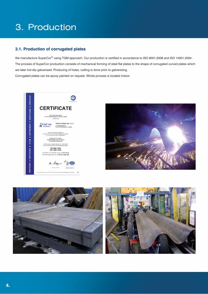
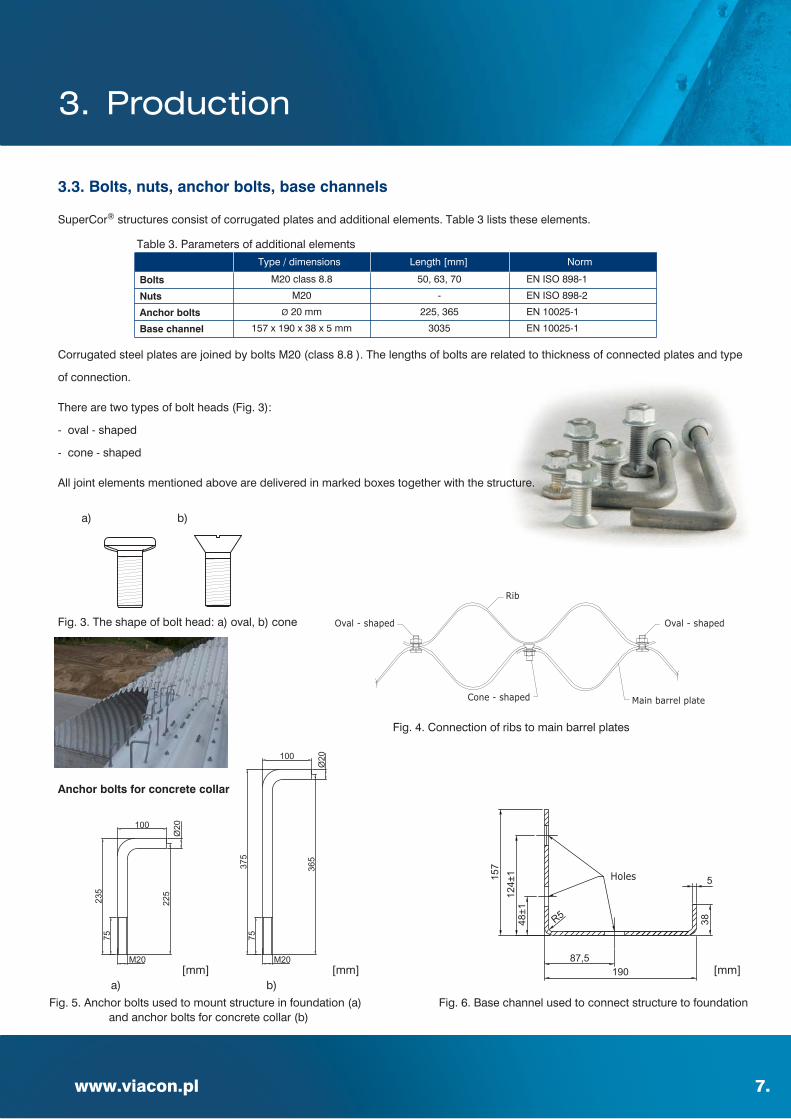
Corrugated steel plates are joined by bolts M20 (class 8.8 ). The lengths of bolts are related to thickness of connected plates and type
of connection.
There are two types of bolt heads (Fig. 3):
- oval - shaped
- cone - shaped
All joint elements mentioned above are delivered in marked boxes together with the structure.
SuperCor® structures consist of corrugated plates and additional elements. Table 3 lists these elements.
a) b)
a) b)
Fig. 4. Connection of ribs to main barrel plates
Fig. 5. Anchor bolts used to mount structure in foundation (a)and anchor bolts for concrete collar (b)
Fig. 6. Base channel used to connect structure to foundation
Type / dimensions Length [mm] Norm
Bolts
Nuts
Anchor bolts
Base channel
M20 class 8.8
M20
Ø 20 mm
157 x 190 x 38 x 5 mm
50, 63, 70
-
225, 365
3035
EN ISO 898-1
EN ISO 898-2
EN 10025-1
EN 10025-1
3.3. Bolts, nuts, anchor bolts, base channels
Table 3. Parameters of additional elements
Fig. 3. The shape of bolt head: a) oval, b) cone
Anchor bolts for concrete collar
[mm] [mm] [mm]
3. Production

8.
Design process includes the following:
- design of SuperCor® structure (including assembly and backfilling procedure)
- design of engineered backfill
- design of foundation
- design of in and outlet fitting elements
SuperCor® structures are designed for all road and railway live load classes acc. to Eurocode 1 EN 1991-2 and for national standards
as well as for (STANAG 2021) loads.
4. Design / construction
4.1. Scope of design
The following algorithm should be used when designing of SuperCor®
structures:
- specify the function of a structure bridge (culvert, viaduct,
ecological crossing, etc.)
- choose the shape (for underpasses, ecological crossings,
adjust to box clearance)
- determine water flow and light (for culverts and bridges)
- choose the type of foundation and specify material
- specify the cover depth
- determine type of dead and live load (for seismic areas specify
seismic zone)
- specify the engineered backfill material and its installation procedure
- make static calculations as well as specify deformations during construction
- select the corrosion protection depending on required durability
- choose the assembly procedure (estimate the labor and the cost of assembly)
- design of inlet and outlet
- design skewed part of a structure
4.2. Design algorithm

9.
4. Design / construction
www.viacon.pl
Contact us for help in static calculations of SuperCor® structures.
SuperCor® structures are dimensioned with use of Swedish design method developed by prof. Sundquist and prof. Pettersson.
They can also be designed with the use of other methods, approved by producer of the structures, e.g. CHBDC. In complex cases finite
element method (FEM) can be used.
4.3. Dimensioning
In order to select a typical shape of a structure please use tables provides on (pages 34-44). These tables include standard shapes.
Other shapes are available on request.
A profile of a structure should fit to a clearance box.
Allow for tolerances of structure dimensions.
Acceptable tolerances are given in chapter 7.
4.4. Selection of structure cross section

10.
Definition of the cover depth for road structures:
Vertical distance between top of a steel structure main barrel and top of the pavement including the pavement layer.
Definition of the cover depth for railway structures:
Vertical distance between top of a steel structure main barrel and bottom of railway sleeper.
Box structures
Depth of cover for box structure should be:
0,45 ≤ hc ≤ 1,5 [m]
Minimum cover depth also depends on the thickness of the pavement layer (Gn) and should not be less than:
hc = Gn + 0,15 [m]
Other shapes
For arch, round, elliptical shapes estimated cover depth is calculated using the formula:
hc = 0,1 × B [m]
where B – span of the structure [m]
Lover cover depth is permissible when appropriate static calculations are conducted. Maximum depth of a cover is always designed
individually. For high cover depth load reduction techniques are available.
Please contact us for advice.
4.5. Cover depth
4. Design / construction
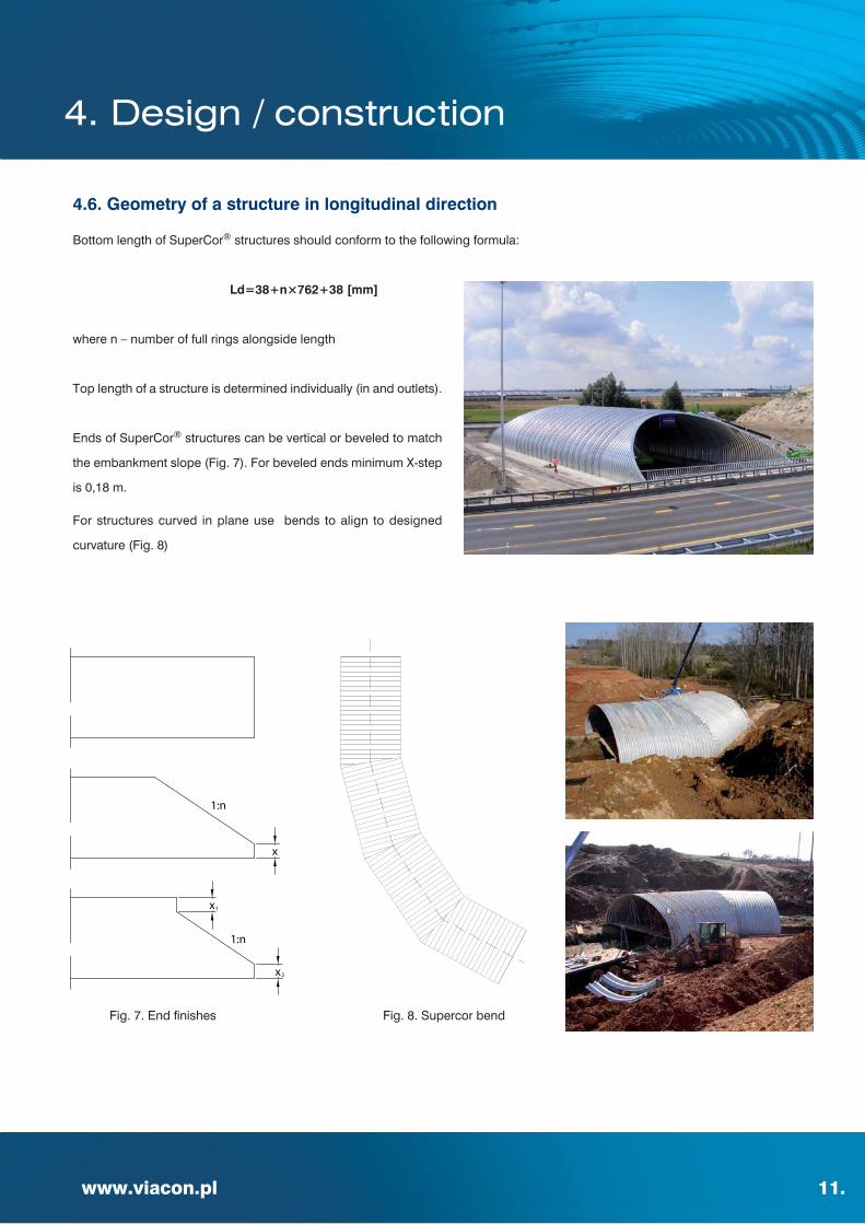
Bottom length of SuperCor® structures should conform to the following formula:
Ld=38+n×762+38 [mm]
where n – number of full rings alongside length
Top length of a structure is determined individually (in and outlets).
Ends of SuperCor® structures can be vertical or beveled to match
the embankment slope (Fig. 7). For beveled ends minimum X-step
is 0,18 m.
For structures curved in plane use bends to align to designed
curvature (Fig. 8)
www.viacon.pl 11.
Fig. 7. End finishes Fig. 8. Supercor bend
x
x
x1
2
1:n
1:n
4.6. Geometry of a structure in longitudinal direction
4. Design / construction

12.
Minimum permissible angle for skewed ends is 55º.
Concrete collars are used for large skews .
Steel meshes attached to SuperCor® structure can be also used
for skewed areas.
Please contact us for advice.
Fig. 9. Skewed structure
4.7. Skew angles
4. Design / construction

www.viacon.pl 13.
4.8. Reinforcing ribs
Reinforcing ribs should be used when flexural capacity of the section is exceeded.
Ribs can be used for all shapes of structures.
Reinforcing ribs:
in cross section (Fig. 10)
– in haunch and crown
– on whole perimeter
In order to get a bigger capacity, space between main barrel and reinforcing ribs can be filled with concrete (EC ribs).The use of EC ribs
can be necessary for large span structures. C25/30 concrete is used as filling acc. to EN 206-1:2000. Thanks to such a sulution used for
arch structures, bigger cross sectional area is achieved, which leads to decrease of compression stresses in steel wall. For boxes,
higher flexural capacity is reached by connecting ribs to the main barrel.
in longitudinal section (Fig. 11)
- continuous – placed on the whole top length of the structure
- spaced at intervals of 762 mm, 1143 mm or 1524 mm
Fig. 10. Placement of the ribs in cross section of the structure
4. Design / construction
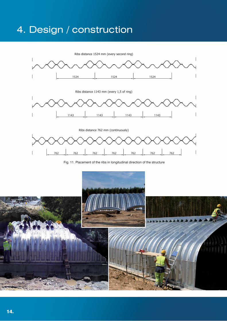
Fig. 11. Placement of the ribs in longitudinal direction of the structure
14.
4. Design / construction
www.viacon.pl 15.
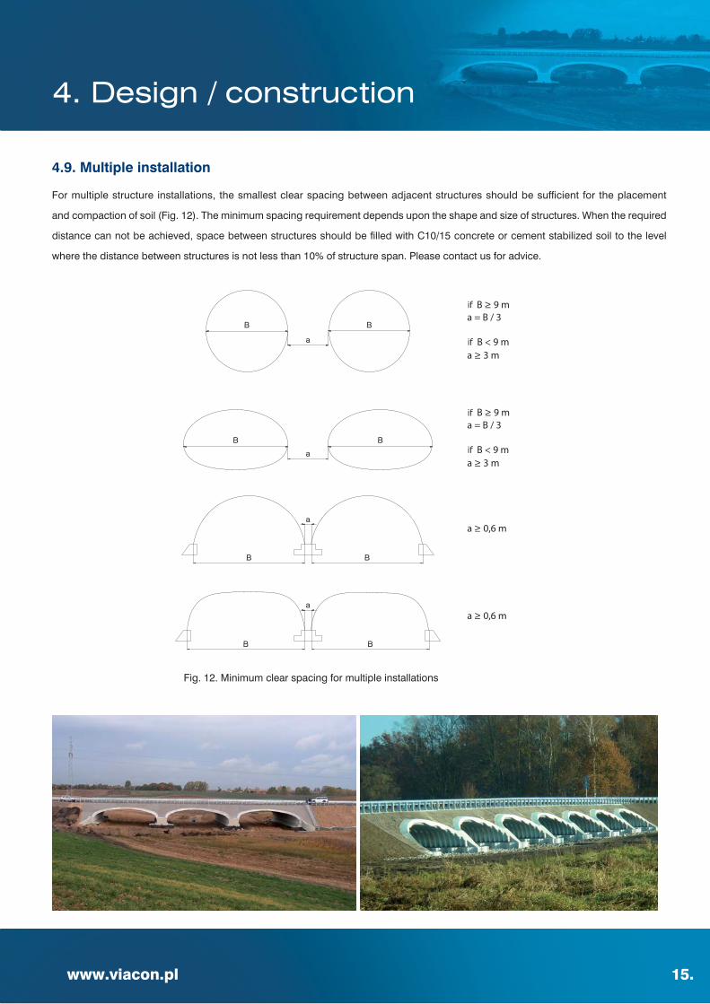
For multiple structure installations, the smallest clear spacing between adjacent structures should be sufficient for the placement
and compaction of soil (Fig. 12). The minimum spacing requirement depends upon the shape and size of structures. When the required
distance can not be achieved, space between structures should be filled with C10/15 concrete or cement stabilized soil to the level
where the distance between structures is not less than 10% of structure span. Please contact us for advice.
Fig. 12. Minimum clear spacing for multiple installations
4.9. Multiple installation
4. Design / construction

16.
SuperCor® structures with closed shapes (round, elliptical, pipe-arch) are placed on soil bedding as follows:
- thickness of soil bedding – minimum 60 cm
- top portion of the bedding should be shaped to fit to the bottom plates of a structure
- particular care should be exercised in compacting soil under haunches
- upper 15 cm layer of the bedding should be relatively loose material so that the corrugation can seat in it
SuperCor® structures with open shapes (arches, boxes) are placed on concrete footings, steel footer pads or a full steel invert.
Connection of the structure to the concrete footings is realized by the means of anchor bolts, taking the following into account:
- anchor bolts for concrete foundations to be installed in concrete footings prior to delivery of a SuperCor® structure
- anchor bolts should not stick out from the top of the footing more than 40 mm
- placing of anchor bolts should conform to assembly drawing; the allowable tolerance is ±3 mm in longitudinal direction and ±2 mm
in the transverse direction
- to minimize a risk of mistake, the location of each anchor should always be measured from the starting point (first anchor)
- parallel placement of anchor bolts on each footing and perpendicular placement of each pair of anchor bolts for individual rings
are of great importance; better accuracy, easier assembly of the structure
Fig. 13. Connection of SuperCor® structure with concrete footing
4.10. Foundation
4. Design / construction

www.viacon.pl 17.
Fig. 14. Connection of SuperCor® structure with steel footer pads of a full steel invert
Steel footings must have appropriate erosion control measures.
For design of steel footing (width, thickness, depth, erosion control etc.) please contact us for advice.
SuperCor® Wall
Steel footing
Base channel
4. Design / construction

18.
Material:
- gravel, sand - gravel mix, all - in aggregates and crushed stone can be used as bedding and backfill material
- aggregate grain size depends on size of corrugation profile; for 381x140 mm maximum size is 120 mm
- aggregate grain size should be 0-120 mm, ununiformity coefficient is Cu>5,0, curvature coefficient 1<Cc<3
and permeability k>6 m/24 hours
- soil restrictions apply for area adjacent to a structure (please contact us for advice)
- the use of cohesive soils, organic soils and soils included permafrost is not acceptable
Placing:
- backfill material around the structure should be placed in uncompacted layers maximum 300 mm thick and then compacted
- the fill should be placed on both sides of the structure at the same time, or alternating from one side of the structure to the other side,
to keep it close to the same elevation on both sides of the structure at all times. No more than one layer difference in elevation on each
side should be allowed. Each layer must be compacted to the specified density before adding the next
- backfill material should be compacted to minimum 95% standard Proctor density – in the area of 20 cm next to the structure,
98% standard Proctor density – in the remaining area
In order to increase load bearing capacity/ soil stiffness of surrounding soil geosynthetic and galvanized steel which can be used.
4.11. Bedding and backfill
4. Design / construction

www.viacon.pl 19.
4.12. End treatment (inlet/outlet)
End treatment depends on the way the ends of structure are cut. For beveled ends, slopes can be finished by paving with stones blocks,
etc. For bevel ends with gabion mattresses, waterproof solutions must be applied. Please contact us for advice.
As an alternative to concrete headwalls MSE Walls (for instance ViaWall system) or gabions can be applied.
4. Design / construction

20.
200
Concrete collar is used:
- in order to stiffen inlet and outlet of SuperCor® structure with beveled ends
- as finishing element used as support of end treatment
Concrete collar is applied mostly in following cases:
- structures with skew angles to the road axis , when skew angle on outlet and inlet
is ≤ 65 ° and span is > 3,5m
- structures exceed 6,0 m span
- large skews
Fig. 15. Example of a concrete collar on inlet and outlet of the structure
Contact us for application of steel collars. Formwork for concrete collar
4.13. Concrete collar
4. Design / construction

www.viacon.pl 21.
4.14. Fittings
SuperCor® structures can be equipped with additional elements depending on function of the structure e.g.:
- lighting boxes
- ventilation
- shelves for animals
- technical holes
- others
Please contact us for advice.
4. Design / construction

22.
Hot-dip galvanization is a basic anti-corrosion protection
of SuperCor® structures.
Durability of SuperCor® structures can extend over 100 years.
SuperCor® structures are hot-dip galvanized according
to EN ISO 1461.
If necessary, SuperCor® structures can be provided with
an extra layer of zinc or additional corrosion protection by
epoxy coating called ViaCoat. These solutions are applied
for aggressive environments.
In most cases the extend of corrosion protection by epoxy coating is as follows:
- inside and/or outside on the whole area of a structure
- at inlet and outlet of the structure (1,5 m inside the structure)
- inside up to 0,5 m above mean water level
- as a combination of above mentioned
Most common thickness of epoxy paint is 200 μm, however other thicknesses are possible. Please contact us of advice.
Following factors have an influence on structure’s durability:
- aggressiveness of an environment
- application of structure
- draining solutions
- abrasion
- installation damages
- corrosion protection
- plate thickness
- quality and frequency maintenance
4.15. Durability
Fig. 16. Epoxy coating protection
4. Design / construction

www.viacon.pl 23.
Procedure of calculating durability of SuperCor® structures:
- define the function of a structure
- define the required durability (lifetime) of a structure
- define the aggressiveness of the environment (water, backfill, air)
- select the type of a structure
- specify the plate thickness based on static calculations (acc. to Sundquist-Petterson method)
- specify the corrosion protection (thickness of zinc coating, paint coating, extend of painting, painting procedure)
- define annual loss of the protection layers in upper and lower part of a structure
- calculate the structure durability by considering corrosion progress over service lifetime
- compare calculated durability with the required
- adjust the anticorrosion solution and if required repeat the calculations
In cases, when the durability of SuperCor® structure is not enough, following measures can be taken :
- change corrosion protection (thickness of zinc layer, paint coat)
- increase the plate thickness
- adjust the shape of a structure and section stiffness to allow for more corrosion reserve
Durability of the ViaCoat system is higher than sum of durability of the protection layers and can be calculated as:
SD=α * (SC+SZ)
where:
SD – total durability of the protection layer [years]
SC – durability of zinc coat [years]
SZ – durability of the epoxy coat [years]
α – synergy factor (from 1,5 to 2,5) for 200 μm thick paint layer α = 1,5; for 400 μm thick paint layer α = 1,75
4. Design / construction
5. Installation and construction procedures
24.
5.1. Delivery
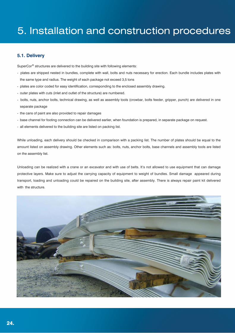
SuperCor® structures are delivered to the building site with following elements:
- plates are shipped nested in bundles, complete with wall, bolts and nuts necessary for erection. Each bundle includes plates with
the same type and radius. The weight of each package not exceed 3,5 tons
- plates are color coded for easy identification, corresponding to the enclosed assembly drawing.
- outer plates with cuts (inlet and outlet of the structure) are numbered.
- bolts, nuts, anchor bolts, technical drawing, as well as assembly tools (crowbar, bolts feeder, gripper, punch) are delivered in one
separate package
- the cans of paint are also provided to repair damages
- base channel for footing connection can be delivered earlier, when foundation is prepared, in separate package on request.
- all elements delivered to the building site are listed on packing list.
While unloading, each delivery should be checked in comparison with a packing list. The number of plates should be equal to the
amount listed on assembly drawing. Other elements such as: bolts, nuts, anchor bolts, base channels and assembly tools are listed
on the assembly list.
Unloading can be realized with a crane or an excavator and with use of belts. It’s not allowed to use equipment that can damage
protective layers. Make sure to adjust the carrying capacity of equipment to weight of bundles. Small damage appeared during
transport, loading and unloading could be repaired on the building site, after assembly. There is always repair paint kit delivered
with the structure.
www.viacon.pl 25.
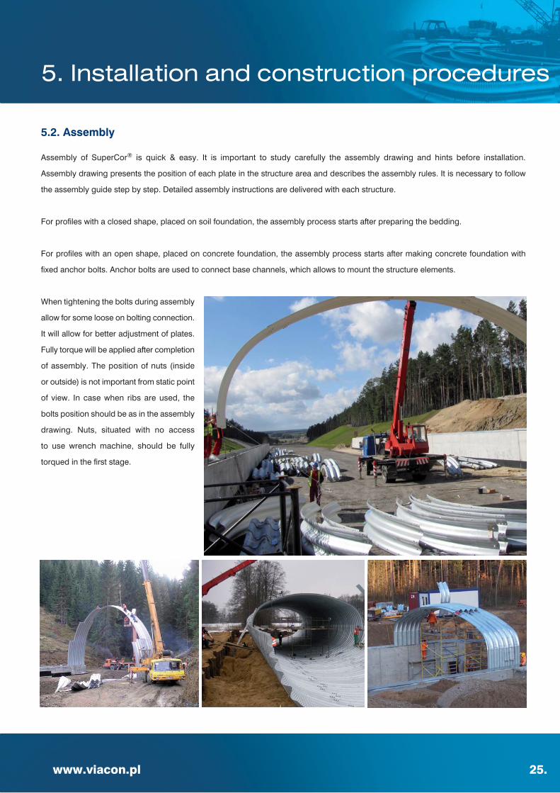
5.2. Assembly
Assembly of SuperCor® is quick & easy. It is important to study carefully the assembly drawing and hints before installation.
Assembly drawing presents the position of each plate in the structure area and describes the assembly rules. It is necessary to follow
the assembly guide step by step. Detailed assembly instructions are delivered with each structure.
For profiles with a closed shape, placed on soil foundation, the assembly process starts after preparing the bedding.
For profiles with an open shape, placed on concrete foundation, the assembly process starts after making concrete foundation with
fixed anchor bolts. Anchor bolts are used to connect base channels, which allows to mount the structure elements.
When tightening the bolts during assembly
allow for some loose on bolting connection.
It will allow for better adjustment of plates.
Fully torque will be applied after completion
of assembly. The position of nuts (inside
or outside) is not important from static point
of view. In case when ribs are used, the
bolts position should be as in the assembly
drawing. Nuts, situated with no access
to use wrench machine, should be fully
torqued in the first stage.
5. Installation and construction procedures

26.
5.3. Torque of bolts
For connection of corrugated plates in SuperCor® structures bolts M20 with nuts are used. Bolts and nuts are color coded for ease
in identification and delivered together with steel plates in separate packages.
Final torque should be done after whole structure is assembled but before backfilling. Bolts should be tighten progressively and uniformly,
starting from the center of the structure towards both ends. During backfilling checks of torque should be done as the actual bolt torque
can decrease slightly due to deformation.
The recommended torque is:
Minimum of 300 Nm, maximum of 360 Nm for structures with spans up to 7,0 m
Minimum of 360 Nm, maximum of 450 Nm for structures with spans more than 7,0 m
Control of torque.
5% of the whole number of bolts should be checked for torque. Minimum
95% of checked bolts must have required torque and the torque
of remaining 5% can not be less than 250 Nm.
The measurements are realized with use of dynamometrical key, with
a valid calibration certificate.
5. Installation and construction procedures
www.viacon.pl 27.
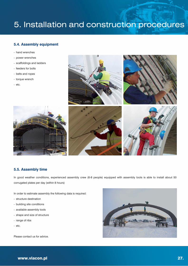
5.4. Assembly equipment
- hand wrenches
- power wrenches
- scaffoldings and ladders
- feeders for bolts
- belts and ropes
- torque wrench
- etc.
5.5. Assembly time
In good weather conditions, experienced assembly crew (6-8 people) equipped with assembly tools is able to install about 50
corrugated plates per day (within 8 hours)
In order to estimate assembly the following data is required:
- structure destination
- building site conditions
- available assembly tools
- shape and size of structure
- range of ribs
- etc.
Please contact us for advice.
5. Installation and construction procedures

28.
5.6. Deformation during backfilling
During backfilling SuperCor® structure will deform developing soil - structure interaction.
The Supercor structure with surrounding soil, constitute soil - steel composite structure with soil being a major load carrying component.
Deformations of the structure should be controlled.
Please contact us for estimation of deformation of SuperCor® structure during backfilling.
Fig. 17. Example of structure deformation during backfilling (Machelski 2008)
w - vertical deflection z - cover depth
5. Installation and construction procedures

www.viacon.pl 29.
5.7. Shape control
Structure must be checked periodically during the backfilling procedure to ensure the shape is consistent with the producer’s
recommendation.
Once one full ring of structure is assembled, preliminary shape control should be performed.
Shape checks should be carried out both during and after assembly.
It is recommended that the producer’s representative be present during erection and backfilling of the structure.
Control of compaction during construction is the responsibility of the contractor.
Please contact us for advise in shape control.
5. Installation and construction procedures

30.
SuperCor® structures are also commonly used to repair old bridges where there
are no possibilities to build a new one. This method is called relining. Corrugated
steel structure is placed inside the existing structure (bridge / culvert / underpass)
and space between an old bridge / culvert and new structural plate is filled
with concrete C12.5/15. This method allows to strengthen the structures without
any traffic stops and eliminates the necessity of remaining the old structure.
The control of pouring concrete between existing structure and new steel
structure should be done by revision holes. During pouring concrete
it is necessary to control deformations of SuperCor®. They shouldn’t exceed
maximum allowed in section No. 7 “Tolerances”. In a case where so called “open” shapes will be used for relining there is a need to make
concrete footings which could be connected to existing one. Existing footings can be used also but it will require separate analysis
or expertise.
6. Relining

www.viacon.pl 31.
Plate dimensions tolerances:
- length and width of the plate ±7mm
- length and height of the corrugation ±5mm
- distance between the holes ±3mm
- plate thickness acc. to EN 10051 +A1
- radius of curvature ±10mm
Tolerances of structure geometry (all profiles excl. Boxes):
Structure dimensions after torque shouldn’t be different than designed with following tolerances:
- span +2%
- rise ±2%
- length ±0.5%
Deformation of cross section after backfilling shouldn’t exceed 2% of the span measured after assembly.
Tolerances of Box structure geometry:
Structure dimensions after torque shouldn’t be different than designed with following tolerances:
- span +2%
- rise +2% / -4%
- length ±0.5%
Deformation of cross section after backfilling shouldn’t exceed 1% of the
span measured after assembly. Based on experience those deflections
are much smaller.
7. Tolerances

32.
SuperCor® tests done in Poland:
- Nowa Ruda SCA-13, SCA-19 Special, SC-48B and SC-23B.
Deformations of steel structure were measured during backfilling (long term test)and under live load
(Class “A” (4x200 kN/axle) acc. to PN-85/S-10030.
- Polanica Zdrój-Szczytna SC-48B and SC-56B.
Strain and deflections measurements. Live load test (Class “A” (4x200 kN/axle)
acc. to PN-85/S-10030.
- Pieńsk SC-33B (bridge under railway).
Live load test. Strain and deflections measurements Class k+2
acc. to PN-85/S-10030.
- Rydzyna SC-57S.
Strain and deflections measurements. Dead load test.
- A4 Motoway SCA-33.
Strain and deflections measurements. Dead load test.
In order to continuously improve design method we cooperate with science centers and research institutes in Europe. Effect of this
collaboration is number of research programs including SuperCor® structures.
8. Tests

www.viacon.pl 33.
SuperCor® abroad tests (selected):
- Giman (Sweden) SC-56B. Strain and deflections measurements.
- Jarpas (Sweden) SC-35B and SC-60B
- Male Zernoseky (Czech Republic) SC-19B
- Alberta Stone Mine White Horse Creek (Canada) SC-92SA
- Tests of composite effect (barrel+rib) (Canada)
Tests mentioned above were done to:
- scale and verify the calculation methods
- optimize design process
- confirm safety of solution especially large span structures

34.
SC-B
SC-SA
SC-NA
SC-R
SC-OA
SC-HA
9. Profiles

www.viacon.pl 35.
SC-R
Type B [mm] H [mm] A [m2] Rc [mm] Total S*
SC-66R 8 400 8 400 55,42 4 200 66
SC-68R 8 650 8 650 58,77 4 325 68
SC-70R 8 910 8 910 62,35 4 455 70
SC-72R 9 170 9 170 66,04 4 585 72
SC-74R 9 430 9 430 69,84 4 715 74
SC-76R 9 690 9 690 73,75 4 845 76
SC-78R 9 950 9 950 77,76 4 975 78
SC-80R 10 200 10 200 81,71 5 100 80
SC-82R 10 460 10 460 85,93 5 230 82
SC-84R 10 720 10 720 90,26 5 360 84
SC-86R 10 980 10 980 94,69 5 490 86
SC-88R 11 240 11 240 99,23 5 620 88
SC-90R 11 500 11 500 103,87 5 750 90
SC-94R 12 020 12 020 113,47 6 010 94
SC-98R 12 530 12 530 123,31 6 265 98
SC-102R 13 050 13 050 133,76 6 525 102
SC-106R 13 570 13 570 144,63 6 785 106
SC-110R 14 080 14 080 155,70 7 040 110
SC-114R 14 600 14 600 167,42 7 300 114
SC-118R 15 120 15 120 179,55 7 560 118
SC-122R 15 640 15 640 192,12 7 820 122
9. Profiles

Type B [mm] H [mm] A [m2] Rt [mm] α [º] Rs [mm] β [º] L [mm] δ [º] Total S*
SC-1B 3 170 1 180 3,12 8 820 7,36 1 016 72,32 406 14,00 11
SC-2B 3 550 1 420 4,33 8 820 9,96 1 016 75,02 559 10,00 13
SC-3B 3 840 1 465 4,94 8 820 12,56 1 016 77,41 517 6,31 14
SC-4B 3 965 2 210 7,35 8 820 9,87 1 016 72,09 1 430 12,98 17
SC-5B 3 865 1 260 4,19 8 820 12,71 1 016 73,28 385 10,37 13
SC-6B 4 105 1 860 6,55 8 820 12,51 1 016 72,07 1 024 11,68 16
SC-7B 4 210 1 310 4,78 8 820 15,32 1 016 73,29 389 9,05 14
SC-8B 4 735 1 960 8,14 8 820 17,74 1 016 72,08 1 023 9,05 18
SC-9B 4 550 1 360 5,38 8 820 17,93 1 016 73,30 389 7,74 15
SC-10B 4 890 1 610 6,96 8 820 20,42 1 016 74,73 562 5,06 17
SC-11B 4 860 2 365 10,08 8 820 17,71 1 016 72,10 1 434 9,05 20
SC-12B 5 155 2 420 11,06 8 820 20,45 1 016 72,36 1 423 7,42 21
SC-13B 5 215 1 670 7,71 8 820 23,01 1 016 74,74 565 3,76 18
SC-14B 5 360 2 075 9,88 8 820 23,00 1 016 72,07 1 023 6,43 20
SC-15B 5 320 1 440 6,61 8 820 23,57 1 016 69,69 415 8,53 17
SC-16B 5 445 2 480 12,05 8 820 22,95 1 016 72,09 1 431 6,44 22
SC-17B 5 655 1 505 7,33 8 820 26,17 1 016 69,69 417 7,22 18
SC-18B 5 955 2 645 14,23 8 820 27,67 1 016 72,36 1 473 3,80 24
SC-19B 5 895 1 595 8,15 8 820 28,31 1 016 72,36 405 3,49 19
SC-20B 6 165 1 900 10,31 8 820 30,29 1 016 72,36 658 2,50 21
SC-21B 6 235 2 715 15,36 8 820 30,28 1 016 72,36 1 474 2,50 25
SC-22B 6 320 1 645 8,91 8 820 31,43 1 016 69,69 420 4,60 20
SC-23B 6 480 1 975 11,25 8 820 32,91 1 016 72,36 661 1,19 22
SC-24B 6 495 2 380 13,89 8 820 32,89 1 016 72,36 1 066 1,20 24
SC-25B 6 645 1 720 9,77 8 820 34,04 1 016 69,69 421 3,29 21
SC-26B 6 970 1 795 10,66 8 820 36,67 1 016 69,68 418 1,98 22
SC-27B 7 000 2 200 13,50 8 820 36,69 1 016 69,68 823 1,97 24
SC-28B 7 025 2 610 16,36 8 820 36,76 1 016 70,36 1 234 1,26 26
SC-29B 7 290 1 870 11,57 8 820 39,30 1 016 69,68 411 0,67 23
SC-30B 7 300 2 286 14,6 8 820 39,30 1 016 69,68 826 0,67 25
SC-31B 7 310 2 690 17,56 8 820 39,31 1 016 69,68 1 231 0,66 27
SC-32B 7 315 3 095 20,51 8 820 39,27 1 016 69,69 1 637 0,67 29
SC-33B 7 405 1 680 10,21 8 820 39,29 1 016 58,98 418 11,38 22
SC-34B 7 800 1 965 12,7 8 820 41,91 1 016 58,97 620 10,08 24
SC-35B 7 945 2 370 15,89 8 820 41,92 1 016 58,97 1 031 10,07 26
SC-36B 8 575 1 920 13,9 11 430 36,45 1 016 69,69 419 2,09 26
SC-37B 8 605 2 325 17,38 11 430 36,45 1 016 69,68 824 2,10 28
SC-38B 8 635 2 735 20,91 11 430 36,45 1 016 69,68 1 234 2,10 30
36.
SC-B
9. Profiles

37.
SC-B
Type B [mm] H [mm] A [m2] Rt [mm] α [º] Rs [mm] β [º] L [mm] δ [º] Total S*
SC-39B 9 145 1 940 14,64 11 430 39,49 1 016 64,31 419 5,94 27
SC-40B 9 225 2 345 18,36 11 430 39,47 1 016 64,33 827 5,94 29
SC-41B 9 310 2 750 22,11 11 430 39,47 1 016 64,32 1 234 5,95 31
SC-42B 9 810 2 105 16,9 11 430 43,55 1 016 64,31 416 3,91 29
SC-43B 9 865 2 510 20,89 11 430 43,54 1 016 64,31 823 3,92 31
SC-44B 9 920 2 920 24,94 11 430 43,54 1 016 64,31 1 234 3,92 33
SC-45B 10 460 2 285 19,42 11 430 47,58 1 016 64,32 418 1,89 31
SC-46B 10 485 2 690 23,66 11 430 47,57 1 016 64,33 824 1,89 33
SC-47B 10 515 3 100 27,97 11 430 47,59 1 016 64,32 1 233 1,89 35
SC-48B 10 895 2 355 20,6 11 430 50,09 1 016 61,63 419 3,33 32
SC-49B 10 940 2 760 25,02 11 430 50,08 1 016 61,64 825 3,32 34
SC-50B 10 990 3 165 29,46 11 430 50,10 1 016 61,63 1 230 3,32 36
SC-51B 11 645 2 530 32,3 11 430 54,66 1 016 58,96 418 3,71 34
SC-52B 11 700 2 935 28,04 11 430 54,68 1 016 58,95 823 3,71 36
SC-53B 11 750 3 345 32,83 11 430 54,67 1 016 59,07 1 232 3,60 38
SC-54B 12 270 2 745 26,46 11 430 58,73 1 016 58,96 421 1,68 36
SC-55B 12 290 3 150 36,45 11 430 58,71 1 016 58,96 827 1,69 38
SC-56B 12 315 3 555 36,45 11 430 58,72 1 016 58,96 1 232 1,68 40
SC-57B 13 028 2 830 30,73 16 430 39,39 1 454 68,70 540 1,61 39
SC-58B 13 050 3 236 36,02 16 430 39,39 1 454 68,70 946 1,61 41
SC-59B 14 092 3 071 35,61 16 430 43,75 1 454 66,85 571 1,28 42
SC-60B 14 111 3 477 41,34 16 430 43,75 1 454 66,87 977 1,26 44
SC-61B 15 020 3 168 38,38 16 430 47,62 1 454 64,95 471 1,24 44
SC-62B 15 038 3 574 44,48 16 430 47,62 1 454 64,94 875 1,25 46
SC-63B 15 579 3 845 49,46 16 430 49,39 1 454 61,12 1 130 4,19 48
SC-64B 15 748 3 994 52,12 16 430 50,10 1 454 61,12 1 232 3,83 49
www.viacon.plwww.viacon.pl
9. Profiles

38.
SC-SA
Type B [mm] H [mm] A [m2] Rc [mm] α [º] Total S*
SC-27SA 6 990 3 495 19,19 3 495 180 27
SC-28SA 7 250 3 625 20,64 3 625 180 28
SC-29SA 7 508 3 754 22,14 3 754 180 29
SC-30SA 7 766 3 883 23,68 3 883 180 30
SC-31SA 8 026 4 013 25,30 4 013 180 31
SC-32SA 8 284 4 142 26,95 4 142 180 32
SC-33SA 8 542 4 271 28,65 4 271 180 33
SC-34SA 8 802 4 401 30,42 4 401 180 34
SC-35SA 9 060 4 530 32,23 4 530 180 35
SC-36SA 9 320 4 660 34,11 4 660 180 36
SC-37SA 9 578 4 789 36,03 4 789 180 37
SC-38SA 9 836 4 918 37,99 4 918 180 38
SC-39SA 10 096 5 048 40,03 5 048 180 39
SC-40SA 10 354 5 177 42,10 5 177 180 40
SC-41SA 10 612 5 306 44,22 5 306 180 41
SC-42SA 10 872 5 436 46,42 5 436 180 42
SC-43SA 11 130 5 565 48,65 5 565 180 43
SC-44SA 11 390 5 695 50,95 5 695 180 44
SC-45SA 11 648 5 824 53,28 5 824 180 45
SC-46SA 11 906 5 953 55,67 5 953 180 46
SC-47SA 12 166 6 083 58,12 6 083 180 47
SC-48SA 12 424 6 212 60,62 6 212 180 48
SC-49SA 12 682 6 341 63,16 6 341 180 49
SC-50SA 12 942 6 471 65,78 6 471 180 50
SC-51SA 13 200 6 600 68,42 6 600 180 51
SC-52SA 13 458 6 729 71,12 6 729 180 52
SC-53SA 13 718 6 859 73,90 6 859 180 53
SC-54SA 13 976 6 988 76,71 6 988 180 54
SC-55SA 14 234 7 117 79,56 7 117 180 55
SC-56SA 14 494 7 247 82,50 7 247 180 56
SC-57SA 14 752 7 376 85,46 7 376 180 57
SC-58SA 15 012 7 506 88,50 7 506 180 58
SC-59SA 15 270 7 635 91,57 7 635 180 59
SC-60SA 15 528 7 764 94,69 7 764 180 60
SC-61SA 15 788 7 894 97,88 7 894 180 61
SC-62SA 16 046 8 023 101,11 8 023 180 62
SC-63SA 16 304 8 152 104,39 8 152 180 63
SC-64SA 16 564 8 282 107,74 8 282 180 64
9. Profiles
www.viacon.pl 39.
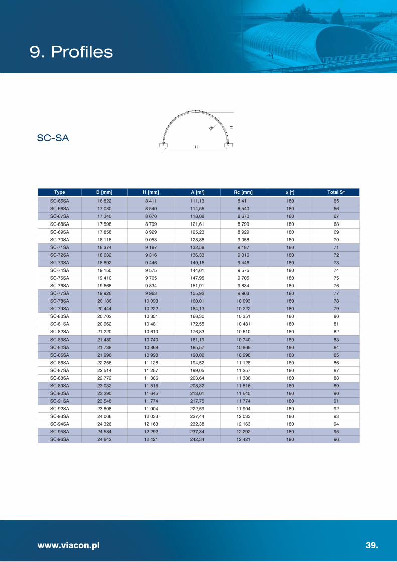
SC-SA
Type B [mm] H [mm] A [m2] Rc [mm] α [º] Total S*
SC-65SA 16 822 8 411 111,13 8 411 180 65
SC-66SA 17 080 8 540 114,56 8 540 180 66
SC-67SA 17 340 8 670 118,08 8 670 180 67
SC-68SA 17 598 8 799 121,61 8 799 180 68
SC-69SA 17 858 8 929 125,23 8 929 180 69
SC-70SA 18 116 9 058 128,88 9 058 180 70
SC-71SA 18 374 9 187 132,58 9 187 180 71
SC-72SA 18 632 9 316 136,33 9 316 180 72
SC-73SA 18 892 9 446 140,16 9 446 180 73
SC-74SA 19 150 9 575 144,01 9 575 180 74
SC-75SA 19 410 9 705 147,95 9 705 180 75
SC-76SA 19 668 9 834 151,91 9 834 180 76
SC-77SA 19 926 9 963 155,92 9 963 180 77
SC-78SA 20 186 10 093 160,01 10 093 180 78
SC-79SA 20 444 10 222 164,13 10 222 180 79
SC-80SA 20 702 10 351 168,30 10 351 180 80
SC-81SA 20 962 10 481 172,55 10 481 180 81
SC-82SA 21 220 10 610 176,83 10 610 180 82
SC-83SA 21 480 10 740 181,19 10 740 180 83
SC-84SA 21 738 10 869 185,57 10 869 180 84
SC-85SA 21 996 10 998 190,00 10 998 180 85
SC-86SA 22 256 11 128 194,52 11 128 180 86
SC-87SA 22 514 11 257 199,05 11 257 180 87
SC-88SA 22 772 11 386 203,64 11 386 180 88
SC-89SA 23 032 11 516 208,32 11 516 180 89
SC-90SA 23 290 11 645 213,01 11 645 180 90
SC-91SA 23 548 11 774 217,75 11 774 180 91
SC-92SA 23 808 11 904 222,59 11 904 180 92
SC-93SA 24 066 12 033 227,44 12 033 180 93
SC-94SA 24 326 12 163 232,38 12 163 180 94
SC-95SA 24 584 12 292 237,34 12 292 180 95
SC-96SA 24 842 12 421 242,34 12 421 180 96
9. Profiles

40.
SC-NA
Type Bmax [mm] B [mm] H [mm] A [m2] Rt [mm] α [º] Rs [mm] β [º] δ [º] Total S*
SC-1NA 8 000 7 994 3 594 23,53 9 930 10,06 3 430 87,29 2,32 30,0
SC-2NA 9 000 8 983 3 760 28,15 9 930 18,95 3 430 84,57 4,04 33,0
SC-3NA 9 500 9 455 3 956 31,54 9 930 23,43 3 430 84,81 6,53 35,0
SC-4NA 10 000 9 967 3 961 33,14 9 930 27,95 3 430 81,68 5,66 36,0
SC-5NA 10 000 9 740 4 547 38,93 9 930 27,95 3 430 91,66 15,64 39,0
SC-6NA 10 500 10 476 3 974 34,75 9 930 32,52 3 430 78,49 4,75 37,0
SC-7NA 11 000 10 947 4 193 38,53 9 930 37,14 3 430 78,54 7,11 39,0
SC-8NA 11 000 10 697 4 776 44,86 9 930 37,14 3 430 88,52 17,09 42,0
SC-9NA 11 500 11 462 4 221 40,27 9 930 41,82 3 430 75,15 6,06 40,0
SC-10NA 12 000 11 974 4 259 42,02 9 930 46,58 3 430 71,71 5,00 41,0
SC-11NA 12 000 11 781 5 639 57,10 9 930 33,17 4 430 86,19 12,78 47,0
SC-12NA 12 500 12 447 4 501 46,26 9 930 51,42 3 430 71,44 7,15 43,0
SC-13NA 13 000 12 964 4 553 48,18 9 930 56,37 3 430 67,71 5,90 44,0
SC-14NA 13 000 12 745 5 890 64,39 9 930 44,22 4 430 81,68 13,79 50,0
SC-15NA 13 500 13 479 4 612 50,12 9 930 61,43 3 430 63,80 4,52 45,0
SC-16NA 14 000 13 958 4 877 54,88 9 930 66,63 3 430 63,03 6,35 47,0
SC-17NA 14 000 13 872 6 543 75,91 9 930 40,84 5 430 78,37 8,79 54,0
SC-18NA 14 500 14 433 5 150 59,87 9 930 71,99 3 430 62,03 8,03 49,0
SC-19NA 15 000 14 960 5 232 62,15 9 930 77,53 3 430 57,42 6,19 50,0
SC-20NA 15 000 14 780 7 022 87,32 9 930 54,77 5 430 74,17 11,56 58,0
SC-21NA 15 500 15 441 5 520 67,55 9 930 83,31 3 430 55,84 7,50 52,0
SC-22NA 16 000 15 942 4 922 64,47 13 930 51,60 3 430 71,65 7,45 52,0
SC-23NA 16 000 15 870 6 666 89,41 13 930 35,20 5 430 81,28 8,88 59,0
SC-24NA 16 500 16 406 5 168 69,78 13 930 54,65 3 430 72,18 9,51 54,0
SC-25NA 17 000 16 930 5 224 72,02 13 930 57,74 3 430 69,33 8,20 55,0
SC-26NA 17 000 16 909 6 720 94,96 13 930 42,37 5 430 76,38 7,57 61,0
SC-27NA 17 500 17 451 5 285 74,29 13 930 60,88 3 430 66,38 6,82 56,0
SC-28NA 18 000 17 921 5 547 80,14 13 930 64,08 3 430 66,65 8,69 58,0
SC-29NA 18 000 17 886 6 999 104,17 13 930 49,67 5 430 73,46 8,30 64,0
SC-30NA 18 500 18 447 5 617 82,59 13 930 67,32 3 430 63,48 7,14 59,0
SC-31NA 19 000 18 912 5 889 88,82 13 930 70,63 3 430 63,51 8,83 61,0
SC-32NA 19 000 18 926 7 099 110,10 13 930 57,22 5 430 68,07 6,68 66,0
SC-33NA 19 500 19 448 5 968 91,46 13 930 74,01 3 430 60,07 7,08 62,0
SC-34NA 20 000 19 924 6 250 98,10 13 930 77,47 3 430 59,83 8,57 64,0
SC-35NA 20 000 19 919 7 424 120,17 13 930 65,05 5 430 64,47 7,00 69,0
SC-36NA 20 500 20 455 6 339 100,94 13 930 81,01 3 430 56,06 6,57 65,0
SC-37NA 21 000 20 937 6 630 107,96 13 930 84,65 3 430 55,44 7,77 67,0
SC-38NA 21 000 20 892 8 462 144,33 13 930 65,73 6 430 64,56 7,43 75,0
9. Profiles
www.viacon.pl 41.
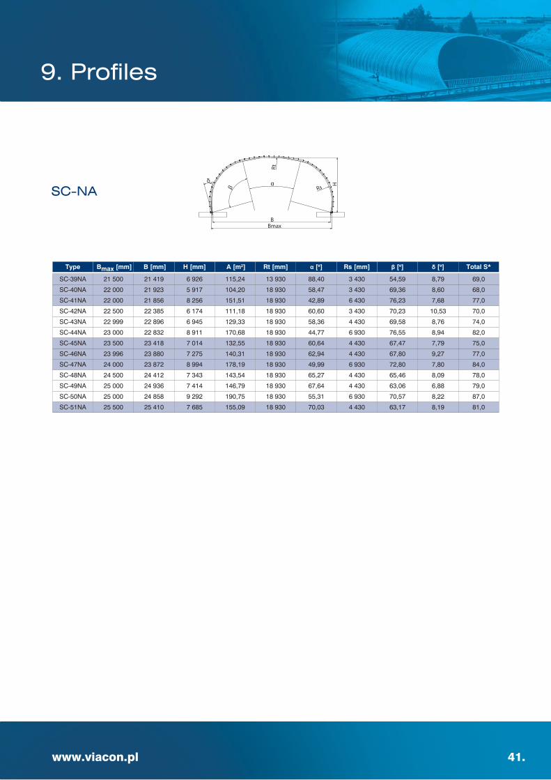
SC-NA
Type Bmax [mm] B [mm] H [mm] A [m2] Rt [mm] α [º] Rs [mm] β [º] δ [º] Total S*
SC-39NA 21 500 21 419 6 926 115,24 13 930 88,40 3 430 54,59 8,79 69,0
SC-40NA 22 000 21 923 5 917 104,20 18 930 58,47 3 430 69,36 8,60 68,0
SC-41NA 22 000 21 856 8 256 151,51 18 930 42,89 6 430 76,23 7,68 77,0
SC-42NA 22 500 22 385 6 174 111,18 18 930 60,60 3 430 70,23 10,53 70,0
SC-43NA 22 999 22 896 6 945 129,33 18 930 58,36 4 430 69,58 8,76 74,0
SC-44NA 23 000 22 832 8 911 170,68 18 930 44,77 6 930 76,55 8,94 82,0
SC-45NA 23 500 23 418 7 014 132,55 18 930 60,64 4 430 67,47 7,79 75,0
SC-46NA 23 996 23 880 7 275 140,31 18 930 62,94 4 430 67,80 9,27 77,0
SC-47NA 24 000 23 872 8 994 178,19 18 930 49,99 6 930 72,80 7,80 84,0
SC-48NA 24 500 24 412 7 343 143,54 18 930 65,27 4 430 65,46 8,09 78,0
SC-49NA 25 000 24 936 7 414 146,79 18 930 67,64 4 430 63,06 6,88 79,0
SC-50NA 25 000 24 858 9 292 190,75 18 930 55,31 6 930 70,57 8,22 87,0
SC-51NA 25 500 25 410 7 685 155,09 18 930 70,03 4 430 63,17 8,19 81,0
9. Profiles

42.
SC-OA
Type Bmax [mm] B [mm] H [mm] A [m2] Rt [mm] α [º] Rs [mm] β [º] δ [º] Total S*
SC-1OA 9 320 9 311 4 542 34,04 5800 27,77 4300 78,76 2,64 36
SC-2OA 9 298 9 061 5 328 41,30 6600 17,46 4300 94,74 13,47 40
SC-3OA 9 538 9 518 4 651 35,92 6100 30,19 4300 78,76 3,85 37
SC-4OA 9 516 9 328 5 245 41,50 6400 25,19 4300 89,41 12,01 40
SC-5OA 9 835 9 817 4 760 37,87 6200 33,42 4400 76,99 3,71 38
SC-6OA 9 889 9 665 5 546 45,67 6600 24,44 4500 90,60 12,81 42
SC-7OA 10 210 10 166 5 024 41,90 6800 30,50 4500 80,40 5,66 40
SC-8OA 10 186 9 754 5 739 49,53 7700 26,97 4300 94,74 18,23 44
SC-9OA 10 523 10 514 4 618 39,65 8300 27,82 4300 78,76 2,67 39
SC-10OA 10 604 10 493 5 232 46,00 7500 33,84 4400 82,20 9,12 42
SC-11OA 10 525 10 200 5 937 52,21 6400 43,19 4600 83,67 15,26 45
SC-12OA 10 829 10 821 4 728 41,69 8200 30,97 4400 76,99 2,48 40
SC-13OA 10 802 10 632 5 317 48,03 8000 34,62 4300 84,08 11,40 43
SC-14OA 10 790 10 397 6 026 54,42 6500 53,16 4500 80,40 16,99 46
SC-15OA 11 116 11 059 4 994 45,88 8400 35,74 4300 78,76 6,63 42
SC-16OA 11 083 10 890 5 403 50,22 8300 36,17 4300 84,08 12,17 44
SC-17OA 11 141 10 695 6 329 59,11 6700 51,59 4700 81,91 17,71 48
SC-18OA 11 347 11 282 5 098 48,06 9400 29,51 4400 82,20 6,96 43
SC-19OA 11 434 11 132 5 626 54,56 9500 31,63 4300 89,41 15,23 46
SC-20OA 11 360 10 825 6 445 61,40 6700 61,91 4600 78,68 19,64 49
SC-21OA 11 698 11 642 5 189 50,29 9400 31,96 4500 80,40 6,39 44
SC-22OA 11 701 11 364 5 719 56,85 9700 33,37 4300 89,41 16,10 47
SC-23OA 11 658 11 159 6 497 64,04 8000 37,51 4800 89,80 18,55 50
SC-24OA 11 998 11 827 5 410 54,64 10000 34,68 4300 84,08 11,43 46
SC-25OA 11 994 11 668 5 844 59,37 9500 36,50 4400 87,41 15,66 48
SC-26OA 11 993 11 696 6 714 67,29 8600 21,49 5400 92,72 13,46 51
SC-27OA 12 260 12 110 5 534 57,13 10800 29,99 4500 85,50 10,49 47
SC-28OA 12 269 11 783 6 094 63,94 10500 33,04 4400 92,62 19,14 50
SC-29OA 12 291 11 902 7 006 72,32 9200 20,09 5500 95,23 15,28 53
SC-30OA 12 571 12 289 5 789 61,76 10800 34,27 4400 87,41 14,55 49
SC-31OA 12 603 12 220 6 234 66,92 11000 29,45 4700 91,68 16,40 51
SC-32OA 12 621 12 135 7 001 74,85 9 800 25,95 5 300 94,44 17,42 54
SC-33OA 12 892 12 703 5 914 64,62 13 000 23,16 4 800 89,80 11,38 50
SC-34OA 12 921 12 554 6 346 69,66 10 800 32,13 4 800 89,80 15,86 52
SC-35OA 12 941 12 347 7 279 80,12 10 500 24,23 5 400 96,97 19,09 56
SC-36OA 13 249 13 082 6 063 67,36 10 700 34,59 4 900 83,30 10,60 51
SC-37OA 13 208 12 880 6 464 72,50 11 700 27,70 5 000 90,85 14,69 53
SC-38OA 13 210 12 745 7 482 83,50 11 600 15,96 5 800 98,30 16,28 57
9. Profiles

www.viacon.pl 43.
SC-OA
Type Bmax [mm] B [mm] H [mm] A [m2] Rt [mm] α [º] Rs [mm] β [º] δ [º] Total S*
SC-39OA 13 449 13 078 6 265 72,06 12 800 28,95 4 700 91,68 16,15 53
SC-40OA 13 427 13 120 6 615 75,37 12 400 24,27 5 200 91,82 13,95 54
SC-41OA 13 407 12 795 7 535 85,97 11 200 22,73 5 600 97,66 19,02 58
SC-42OA 13 742 13 214 6 277 74,10 12 700 34,64 4 400 92,62 19,94 54
SC-43OA 13 749 13 538 6 810 78,63 11 900 23,34 5 600 89,45 11,12 55
SC-44OA 13 838 13 469 7 752 89,95 11 200 16,53 6 200 95,74 14,01 59
SC-45OA 14 064 13 682 6 462 77,55 12 700 32,82 4 800 89,80 16,21 55
SC-46OA 14 066 13 612 6 965 83,52 12 200 30,36 5 200 91,82 17,00 57
SC-47OA 14 253 13 784 7 970 95,83 11 500 20,13 6 200 95,74 15,80 61
SC-48OA 14 292 13 904 6 623 80,50 12 100 36,35 4 900 87,99 16,17 56
SC-49OA 14 383 13 946 7 079 86,59 12 000 32,80 5 300 90,11 16,50 58
SC-50OA 14 440 14 023 8 194 99,18 10 800 19,28 6 500 94,91 14,55 62
SC-51OA 14 662 14 367 6 735 83,73 12 800 32,57 5 200 87,40 13,68 57
SC-52OA 14 682 14 324 7 233 89,95 12 300 30,12 5 600 89,45 14,51 59
SC-53OA 14 704 14 176 8 218 102,07 11 200 24,79 6 300 94,24 16,64 63
SC-54OA 14 917 14 537 6 892 86,54 11 000 48,38 5 000 81,66 15,85 58
SC-55OA 14 965 14 678 7 441 93,42 11 100 35,44 5 900 84,95 12,67 60
SC-56OA 14 989 14 305 8 502 108,04 11 000 29,45 6 300 94,24 18,96 65
SC-57OA 15 274 15 077 7 041 90,22 12 400 33,61 5 700 83,86 10,67 59
SC-58OA 15 316 15 048 7 534 96,62 11 200 37,19 6 000 83,55 12,15 61
SC-59OA 15 235 14 549 8 639 111,44 10 800 32,13 6 400 92,78 18,85 66
9. Profiles

44.
SC-HA
Type Bmax [mm] B [mm] H [mm] A [m2] Rt [mm] α [º] Rs [mm] β [º] Rc [mm] γ [º] δ [º] Total S*
SC-1HA 9 000 8 724 5 168 40,67 9 930 18,95 3 430 80,53 9 930 9,56 9,57 40,0
SC-2HA 10 000 9 690 5 371 47,06 9 930 27,95 3 430 76,02 9 930 10,14 10,14 43,0
SC-3HA 11 000 10 642 5 864 56,27 9 930 33,18 3 730 73,41 9 930 10,89 10,89 47,0
SC-4HA 12 000 11 612 6 113 63,68 9 930 42,95 3 730 68,52 9 930 11,34 11,34 50,0
SC-5HA 13 000 12 662 6 460 72,07 9 930 48,24 4 130 65,88 9 930 10,58 10,58 53,0
SC-6HA 14 000 13 641 7 009 83,57 9 930 54,44 4 530 62,78 9 930 10,92 10,92 57,0
SC-7HA 15 000 14 663 7 351 92,90 9 930 64,38 4 730 57,81 9 930 10,57 10,57 60,0
SC-8HA 16 000 15 543 7 982 111,11 13 930 39,89 4 930 70,06 13 930 10,39 10,40 66,0
SC-9HA 17 000 16 478 8 483 124,98 13 930 45,03 5 130 67,48 13 930 11,10 11,10 70,0
SC-10HA 18 000 17 350 9 207 143,30 13 930 49,67 5 430 65,17 13 930 12,40 12,41 75,0
SC-11HA 19 000 18 409 9 562 155,81 13 930 53,88 5 830 63,06 13 930 11,81 11,81 78,0
SC-12HA 20 000 19 341 10 344 176,71 13 930 56,85 6 430 61,58 13 930 12,48 12,49 83,0
SC-13HA 21 000 20 341 10 922 194,68 13 930 61,33 6 930 59,34 13 930 12,48 12,49 87,0
SC-14HA 22 000 21 397 11 363 216,73 18 930 36,17 7 430 71,92 18 930 10,24 10,25 92,0
SC-15HA 23 000 22 370 11 894 236,33 18 930 38,61 7 830 70,70 18 930 10,47 10,48 96,0
SC-16HA 24 000 23 382 12 463 257,12 18 930 39,75 8 430 70,13 18 930 10,37 10,38 100,0
SC-17HA 25 000 24 374 13 016 278,59 18 930 41,83 8 930 69,09 18 930 10,43 10,44 104,0
9. Profiles

10. Case studies
Location: Railway line E20 near Rzepin town
In 2007 r. over international double truck electrified railway line E20 Section
Rzepin - Polish –German border two animal overpasses were built.
Two SuperCor® SCA-35 low profile Arch’s set on the concrete foundations were
used in two different locations.
Basic parameters are following:
- span – 20,00 m
- rise – 5,97 m
- bottom length– 57,988 m
- corrugation – 381 x 140 mm
SuperCor® SCA-35 structures were
corrosion protected by zinc coat acc. to
EN ISO 1461:2000
Assembly was realized parallel by two
independent crew and took 19 days only.
Structures were assembled using plate by
plate method and partially preassembled
using one crane/structure and two basket
elevators/structure.
Arches were backfilled with sand-gravel mix (0-32mm) and compacted to min 98%
Acc. to standard Proctor density. Height of cover is 1.5 m.
Over each structure geosynthetic (NV geotextile + geomembrane +NV geotextile
“ambrella” were used to protect against rain water leak.
On the top of the overpasses antidazzle fences were built with height 2.5 m.
(West border of Poland)
www.viacon.pl 45.

46.
Location : Highway A2, section Konin – Koło
In 2006 over highway A2 section Konin – Koło two animal overpasses were built.
Both overpasses are consist of two corrugated steel arch structures SuperCor®
SC–57S with span 17,7 m and two MultiPlates structures MP200 G30 with PipeArch
profile. There are the biggest structures of these types in Europe. The structures
were galvanized acc. to EN ISO 1461:2000 and additionally epoxy painted 200 µm
acc. to EN ISO 12944-5.
Each Supercor® SC-57S structure has the following parameters:
- rise – 5,461 m
- span – 17,667 m
- bottom length – 60 m
- corrugation – 381 x 140 mm
Each MultiPlate G-30 structure has the following parameters:
- rise – 8,12 m
- span – 9,36 m
- bottom length – 76 m
- corrugation – 200 x 55 mm
The structure was designed to carry a live load class E acc. to PN–85/S–10030.
Assembly of these 4 structures lasted 2 months. Structure was assembled acc. to
plate–by–plate method with the use of two cranes situated on either side of the
structure and movable scaffold.
10. Case studies

www.viacon.pl 47.
Location: Wągrowiec By Pass
In 2002 at the crossing of a new by pass of Wągrowiec and existing railway
line SuperCor® SC–50B box structure was designed.
The structure has the following parameters:
- rise – 3,165 m
- span – 10,990 m
- bottom length– 40,386 m
- corrugation – 381 x 140 mm
The structure was designed to carry a live load class A acc. to PN–85/S–10030.
The structures were galvanized in acc. to EN ISO 1461:2000
In order to ensure the required railway clearance the steel structure was
founded on concrete footings 5 m high.
The full rings of the structure were first prefabricated and next the rings were
installed on the concrete footings.
The assembly of the whole structure lasted 2 weeks.
At the ends of the structure delicate concrete collars were constructed.
The slopes were paved by means of concrete blocks.
10. Case studies

48.
Location: Baczyn close to Sucha Beskidzka
In 2001 in Baczyn close to Sucha Beskidzka a bridge was destroyed by the flood.
Old bridge was replaced with new corrugated steel structure SuperCor® SC-20B.
The structure has the following parameters:
- rise – 1,9 m
- span – 6,165 m
- bottom length– 12,192 m
- corrugation – 381 x 140 mm
The structures was galvanized in acc. to EN ISO 1461:2000.
The structure were installed on the concrete footings.
The assembly of the whole structure lasted 6 days.
The cost of steel structure was much less than traditional bridge construction.
10. Case studies

www.viacon.pl 49.
Location: National Road No. 5 Poznań – Wrocław, section Komorniki – Głuchowo, Trzebaw
In 2003 over National Road No. 5 Poznań – Wrocław between Komorniki and
Głuchowo in Trzebaw building of animal overpass was started with the use of
corrugated steel arch structure SuperCor® SC–57S .
The steel structure has the following parameters:
- rise – 5,461 m
- span – 17,667 m
- bottom length – 55,626 m
- corrugation – 381 x 140 mm
The structures was galvanized in acc. to EN ISO 1461:2000.
The structure was designed to carry a class E live load acc. to PN–85/S–10030.
Assembling of the structure lasted 11 days and was conducted without stopping the
traffic. Structure was assembled acc. to plate–by–plate method with the use of two
cranes situated on either side of the structure and movable scaffold.
Steel structure was backfilled with the use of sand–gravel mix compacted to Standard
Proctor density of minimum 97%. The depth of cover over the steel structure is 1,80 m.
Costs of the structure is 70% of costs of the structure built in traditional technology.
10. Case studies

50.
Location: Gniezno bypass
Three span bridge was built with use of steel box structures SuperCor® in Gniezno in 2004.
Each of the steel box structure SC-59B has the following parameters:
- rise – 3,07 m
- span – 14,075 m
- bottom length – 23,56 m
- corrugation – 381 x 140 mm
The structure were installed on the pile foundation.
SuperCor® SC- 59B structures are hot dip galvanized acc. to EN ISO 1461:2000 with zinc
layer 85 m and additionally epoxy painted 200 μm acc. to EN ISO 12944-5.
The structure were reinforced by steel ribs situated on the whole area.
The assembly lasted 3 weeks in assistance with 8 people crew.
10. Case studies

www.viacon.pl 51.
section „B” Wykroty – Krzyżowa
In 2008 over A4 Motorway on Zgorzelec – Krzyżowa section construction of two animal
overpasses has started. Each of the overpass consists of two SuperCor® SCA-33 arch
structures placed on concrete footings.
Steel structures have following parameters:
- span – 19,50 m
- rise – 5,97 m
- bottom length – 67,89 m
- corrugation profile – 380 x 140 mm
Location: A4 Motorway
10. Case studies

52.
SCA-33 structures are reinforced by means of additional steel plates. In order to
decrease the load on middle footing, helically corrugated steel pipe HelCor Ø2400
mm was used.
SuperCor® SCA-33 structures are hot dip galvanized acc. to EN ISO 1461 and
additionally epoxy painted 200 μm acc. to EN ISO 12944-5.
HelCor pipes are hot dip galvanized with zinc coating thickness of 42 μm and have
polymer Trenchcoat coating 250 μm thick.
Assembly of all 4 structures for two passings lasted 12 weeks.
Wooden fences on top of the passings are installed to separate the animal passage
from view of moving vehicles.
10. Case studies
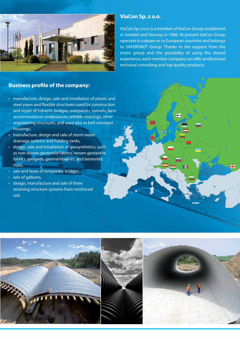
ViaCon Sp. z o.o.
ViaCon Sp. z o.o. is a member of ViaCon Group established in Sweden and Norway in 1986. At present ViaCon Group operates in a dozen or so European countries and belongs to SAFEROAD® Group. Thanks to the support from the entire group and the possibility of using the shared experience, each member company can offer professional technical consulting and top quality products.
Business profile of the company:
• manufacture, design, sale and installation of plastic and steel pipes and flexible structures used for construction and repair of culverts, bridges, overpasses, tunnels, farm accommodation underpasses, wildlife crossings, other engineering structures, and used also as belt conveyor housings,
• manufacture, design and sale of storm water drainage systems and holding tanks,
• design, sale and installation of geosynthetics, such as non-woven geotextile fabrics, woven geotextile fabrics, geogrids, geomembranes, and bentonite mats,
• sale and lease of temporary bridges,• sale of gabions,• design, manufacture and sale of three
retaining structure systems from reinforced soil.

Woven and non-woven geotextiles
HelCor® MultiPlate MP200HelCor PA®PECOR OPTIMA®
Acrow® 700XS® - temporary bridges
Gabions HelCor® wells
PECOR OPTIMA® M wells
SuperCor® Geogrids
HelCor® TC holding tanks Pecor Quattro sewage system
ViaWall B retaining walls ViaBlock retaining wallsViaWall A retaining walls
MP200 pl ok_folder-srodek2.qxd 2012-10-08 15:00 Strona 13
ViaCon Sp. z o.o. ul. Przemysłowa 6 64-130 Rydzyna, Polandphone: +48 65 525 45 45fax: +48 65 525 45 55e-mail: [email protected]
Our goal is to improve products and to cooperate closely with customers, scientific and research centres, public administration and suppliers.
That’s why our motto is:
”Let’s Create a Better Future Together”
www.viacon.pl