Embed Size (px)
Citation preview

J Elast (2017) 129:197–212DOI 10.1007/s10659-016-9606-1
Bulging Brains
J. Weickenmeier1 · P. Saez2 · C.A.M. Butler3 ·P.G. Young4 · A. Goriely5 · E. Kuhl1,6
Received: 23 May 2016 / Published online: 24 October 2016© Springer Science+Business Media Dordrecht 2016
Abstract Brain swelling is a serious condition associated with an accumulation of fluid in-side the brain that can be caused by trauma, stroke, infection, or tumors. It increases thepressure inside the skull and reduces blood and oxygen supply. To relieve the intracranialpressure, neurosurgeons remove part of the skull and allow the swollen brain to bulge out-ward, a procedure known as decompressive craniectomy. Decompressive craniectomy hasbeen preformed for more than a century; yet, its effects on the swollen brain remain poorlyunderstood. Here we characterize the deformation, strain, and stretch in bulging brains us-ing the nonlinear field theories of mechanics. Our study shows that even small swellingvolumes of 28 to 56 ml induce maximum principal strains in excess of 30 %. For radiallyoutward-pointing axons, we observe maximal normal stretches of 1.3 deep inside the bulgeand maximal tangential stretches of 1.3 around the craniectomy edge. While the stretch mag-nitude varies with opening site and swelling region, our study suggests that the locations ofmaximum stretch are universally shared amongst all bulging brains. Our model has the po-tential to inform neurosurgeons and rationalize the shape and position of the skull opening,
B E. [email protected]
1 Department of Mechanical Engineering, Stanford University, Stanford, CA 94305, USA
2 Laboratori de Calcul Numeric, Universitat Politècnica de Catalunya BarcelonaTech,08034 Barcelona, Spain
3 Synopsys/Simpleware, Bradninch Hall, Castle Street, Exeter EX4 3PL, UK
4 College of Engineering, University of Exeter, Exeter, Devon, UK
5 Mathematical Institute, University of Oxford, Oxford OX2 6GG, UK
6 Department of Bioengineering, Stanford University, Stanford, CA 94305, USA

198 J. Weickenmeier et al.
with the ultimate goal to reduce brain damage and improve the structural and functionaloutcomes of decompressive craniectomy in trauma patients.
Keywords Soft matter · Hyperelasticity · Swelling · Finite element analysis ·Neuromechanics · Brain · Craniectomy
Mathematics Subject Classification 74L15 · 92B05 · 92C10 · 92C50
Einen Druck über einen gewissen Grad und über eine gewisse Zeit hinaus hält das Gehirnnicht aus. Darum ist es stets Pflicht, einen Druck auf das ungefährliche Mass von Intensitätund Dauer zu reduciren.
Emil Theodor Kocher [1901]
1 Motivation
Under physiological conditions, the mechanical environment of our brain is tightly regu-lated. The intracranial pressure, for example, lies within a narrow window between 0 and10 mmHg [18]. An increase in intracranial pressure—most commonly caused by traumaticbrain injury, subarachnoid hemorrhage, ischemic stroke or a brain tumor—can be devas-tating or even fatal: It reduces cerebral perfusion, and limits the supply of metabolites andoxygen [8]. As a method of last resort, neurosurgeons remove part of the skull to allowthe swollen brain to bulge outward and facilitate an immediate release of the elevated pres-sure [27]. This life-saving procedure, known as decompressive craniectomy [35], is typi-cally recommended if the intracranial pressure exceeds 20 mmHg for longer than 30 min-utes [25]. While a decompressive craniectomy improves short-term pressure managementand survival, its survivors often experience severe long-term disabilities [23]. To date, theprecise criteria related to the optimal timing of treatment, the optimal location and size ofthe skull opening, and the long-term functional outcome remain unclear.
From a mechanical perspective, a decompressive craniectomy is a compromise betweenmaximizing the management of the intracranial pressure and minimizing the deformationsinduced by the bulging brain [19]. Recent studies have characterized bulge kinematics basedon computerized tomography images before and after a decompressive craniectomy usingnon-linear image registration [44]; yet, little is know about the stress, stretch, and strain in-side the brain. While our mechanical intuition tells us that stretch and strain can be reducedby increasing the opening size, a larger opening area is more prone to infection and clini-cally undesirable [39]. Clinical guidelines suggest opening diameters of about 12 cm [40],but the rationale for this recommendation is rather vague and lacks a clear mechanistic un-derstanding of the bulging process itself.
When aiming to optimize the craniectomy size, it is unclear to which extent the loca-tion of the opening influences the stretch and strain profiles across the brain [13]. The mostcommon procedure in clinical practice is a unilateral craniectomy with an opening on ei-ther the left or the right lateral skull depending on the side of the swelling [35]. Recentclinical studies have challenged the engineering intuition that a collateral craniectomy withthe opening at the site of swelling is less invasive than a contralateral craniectomy withthe opening at the opposite, non-injured side [43]. While the opening size for a unilateralcraniectomy is anatomically limited, a bilateral craniectomy with a bifrontal opening acrossboth hemispheres provides sufficient anatomic space for large opening sizes [27]. Yet, the

Bulging Brains 199
precise bulging kinematics for the different types of craniectomy are far from being com-pletely understood.
Mathematical models and computational simulations can provide analytical and numeri-cal insight into the strain, stretch, and stress fields of bulging solids. Using the classic theoryof contact mechanics [3, 24], we have recently shown that in the small deformation limit,the bulging problem is conceptually similar to an inverted punch problem [19]. This allowsus to solve the bulging problem explicitly for a bulging half-space under plane strain, planestress, and axisymmetric conditions. The explicit analytical solution for the stress field moti-vates the introduction of damage drops, drop-shaped zones of high and low shear stress withsingularities that scale with the inverse square root of the distance from the opening [45].Interestingly, the shape of the bulge, the singularities of the stress profile, and the orientationof the drops are generic for all bulging problems and independent of the constitutive model.These characteristic features also agree nicely with computational simulations, both in thelinear [12] and in the nonlinear [45] regime. However, it remains unclear how these charac-teristics evolve in geometries as complex as the human brain. First attempts along these lineshave modeled the brain via its convex hull embedded in a rigid skull [16], and shown thatshear strains can reach values up to 25 %, even for bulge volumes of only 22 ml [14]. Whilethese numbers clearly highlight the need for a kinematically and constitutively nonlinearformulation, the bulging brain has never been modeled using the nonlinear field theories ofmechanics.
Here we introduce a continuum model for bulging brains in the finite deformation set-ting. We model brain tissue as a swelling, elastically incompressible Mooney-Rivlin solidand illustrate how to translate its mathematical model into a general, nonlinear finite elementenvironment. To demonstrate the features of the bulging problem under finite deformations,we conduct a series of case studies and perform systematic sensitivity analyses with respectto the swelling area, the opening size, and the opening location. We then create a person-alized brain model from magnetic resonance images and simulate two different cases ofcraniectomy, a left unilateral flap and a frontal flap. For both cases, we study three swellingscenarios, swelling in both hemispheres, exclusively in the left hemisphere, and exclusivelyin the right hemisphere. We report and compare displacements, deformations, radial andtangential stretches, and maximum principal strains.
2 Brain Model
To model brain tissue, we adopt a classical hyperelastic constitutive formulation [22]. Wefollow the recommendation to approximate brain as an isotropic material since our deforma-tion rates are moderate [47]. To characterize the brain at finite deformations, we introducethe nonlinear deformation map ϕ and its gradient F = ∇Xϕ with respect to the coordinatesX in the undeformed reference configuration. We allow parts of the brain to swell [29], anddecompose the deformation gradient multiplicatively into an elastic part F e and a swellingpart F s,
F = ∇Xϕ = F e · F s with J = det(F ) = J eJ s. (1)
The Jacobian J denotes the total volume change and J e = det(F e) and J s = det(F s) denotethe volume change associated with the elastic deformation and with swelling. We then maketwo major kinematic assumptions: We assume that the elastic behavior is incompressible,J e = 1, such that the total volume change is caused exclusively by swelling, J = J s, andthat swelling is volumetric, F s = (J s)1/3I , such that the isochoric deformation is purely

200 J. Weickenmeier et al.
elastic F = F e. These assumptions imply that we can decompose the deformation gradientF into a volumetric contribution purely associated with swelling, J = J s, and an isochoriccontribution purely associated with the elastic deformation, F = F e,
F = ∇Xϕ = J 1/3F with J = det(F ) and F = J−1/3F . (2)
We introduce the left Cauchy-Green deformation tensor b and decompose it into itsswelling-induced volumetric contribution in terms of the Jacobian J and its elastic isochoriccontribution b,
b = F · F t = J 2/3b with b = F · F t. (3)
To characterize the swelling-induced deformation, we explore three kinematic metrics asso-ciated with the Green-Lagrange strain tensor,
E = 1
2
[F t · F − I
], (4)
the maximum principal strain, λmaxE , associated with the eigenvalue problem of the Green-
Lagrange strain tensor E,
E · nE = λEnE and λmaxE = max{λE}, (5)
the normal stretch along the axon, and the tangential stretch perpendicular to the axon. Wethen introduce the invariants I1, I2, and I3, in terms of the left Cauchy-Green deformationtensor b,
I1 = tr(b) with ∂I1/∂b = I ,
I2 = 1
2
[tr2(b) − tr
(b2)] with ∂I2/∂b = I1I − b,
I3 = det(b) with ∂J/∂b = 1
2Jb−1
(6)
and their elastic, isochoric counterparts I1, I2, and I3, either in terms of the isochoric leftCauchy-Green deformation tensor b or in terms of the isochoric principal stretches λ1, λ2,and λ3,
I1 = tr(b) = J−2/3 I1 = λ21 +λ2
2 +λ23,
I2 = 1
2
[tr2(b) − tr
(b
2)] = J−4/3 I2 = λ−21 +λ−2
2 +λ−23 ,
I3 = det(b) = J−6/3 I3 = 1.
(7)
Many common constitutive models for brain tissues are special cases of the general Ogdenmodel [33],
ψ =N∑
i=1
ci
αi
[λ
αi
1 + λαi
2 + λαi
3 − 3], (8)
parameterized in terms of the Ogden parameters ci and αi . For the special case of N = 2,with α1 = 2 and α2 = −2, the Ogden model simplifies to the Mooney-Rivlin model [32, 36],
ψ = 1
2c1
[λ2
1 + λ22 + λ2
3 − 3] + 1
2c2
[λ−2
1 + λ−22 + λ−2
3 − 3], (9)
which we can reformulate in terms of the elastic isochoric invariants I1 and I2,
ψ = 1
2c1[I1 − 3] + 1
2c2[I2 − 3]. (10)

Bulging Brains 201
The Mooney-Rivlin parameters c1 and c2 are related to the shear modulus μ as c1 + c2 =12μ, and their values can be identified through finite deformation experiments [15, 31]. Weenforce the elastic incompressibility constraint, J e − 1 = 0, in the form, J − J s = 0, via aLagrange multiplier p, and add the term p[J − J s] to the energy functional,
ψ = 1
2c1[I1 − 3] + 1
2c2[I2 − 3] + p
[J − J s
]. (11)
To derive the stresses, it proves convenient to reformulate the energy in terms of the overallinvariants I1 and I2 and the Jacobian J ,
ψ = 1
2c1
[J−2/3I1 − 3
] + 1
2c2
[J−4/3I2 − 3
] + p[J − J s
]. (12)
We can then directly obtain the Kirchhoff stress,
τ = ∂ψ
∂F· F t = 2
∂ψ
∂b· b = 2
[∂ψ
∂I1
∂I1
∂b+ ∂ψ
∂I2
∂I2
∂b+ ∂ψ
∂J
∂J
∂b
]· b (13)
or, with the derivatives of the invariants in Eq. (6),
τ = 2
[∂ψ
∂I1+ I1
∂ψ
∂I2
]b + 2
∂ψ
∂I2b2 + J
∂ψ
∂JI . (14)
Using the definition of the energy (12), we obtain the following explicit representation of theKirchhoff stress τ for a volumetrically swelling, elastically incompressible, Mooney-Rivlinmaterial [17],
τ = [c1 + I1c2]b − c2b2 −
[1
3I1c1 + 2
3I2c2 + Jp
]I . (15)
The isochoric contributions to the third term, 13 I1c1 + 2
3 I2c2, reflect the fact that we haveformulated the Mooney-Rivlin model in terms of the isochoric invariants I1 and I2 andnot of the total invariants I1 and I2. Even though the elastic behavior is incompressible,the overall behavior is not, and the isochoric invariants I1 and I2 indirectly depend on theamount of swelling J . Rather than rewriting the energy formulation in Eq. (12), we couldhave introduced the Kirchhoff stress as τ = ∂Ψ/∂ b : P · b, where P = ∂ b/∂b denotes thespatial fourth order isochoric projection tensor, to obtain the term, 1
3 I1c1 + 23 I2c2, from the
isochoric projection with P [22].In our continuum model, we prescribe the amount of swelling J s pointwise and phe-
nomenologically rather than modeling the swelling process itself [29]. We gradually in-crease the local tissue volume as �V = [J s − 1.0] · 100 %. In our computational model, werepresent volumetric swelling via volumetric thermal expansion [1], and only allow selectedregions of the cerebral white matter tissue to swell, while all other substructures remainpurely elastic with J s .= 1.0. We enforce the incompressibility constraint J − J s = 0 byusing a hybrid finite element formulation with displacement degrees of freedom for the iso-choric part and pressure degrees of freedom for the volumetric part of the deformation.
3 Bulging of a Hemidisk
Our previous analysis of the bulging of a linear elastic half-space through an opening hasrevealed two interesting features related to damage and stress distributions and relevant tothe problem of craniectomy: Large fiber stretches develop deep in the center of the bulgeand large shear stresses develop around the opening edge [19, 45]. These previous results

202 J. Weickenmeier et al.
Fig. 1 Bulging of a hemidisk.We allow an elastic body to swelllocally, either in a sector of angleα (A) or in a disk (B). Theswelling body bulges out throughan opening of angle β
Fig. 2 Bulging of a hemidisk with a swelling sector. Displacement, vertical displacement, and radial andtangential stretches for frictional contact without sliding (left) and frictionless contact with sliding (right). Infrictional contact without sliding, the solid is pushed outward with large displacements along the symmetryaxis in the center of the bulge. In frictionless contact with sliding, the solid slides along the boundary androtates outward around the opening edge
were obtained analytically under the assumption of uniform swelling in a rectangular half-space geometry. In this section, we study the importance of geometric effects in an idealizedgeometry computationally by systematically varying the location and area of swelling.
3.1 Hemidisk Model
We first consider the bulging problem in a simple two-dimensional geometry. As depictedin Fig. 1, an incompressible isotropic elastic hemidisk is swelling and the deformations areconstrained within the hemidisk except in an opening of angle β . We consider two swellingscenarios: the swelling of a sector with an opening α where both α and β are centered aboutthe axis of symmetry as illustrated in Fig. 1A, and the swelling of a disk where the openingβ is inclined off the axis of symmetry as illustrated in Fig. 1B. We assume that the axonaldirection n is oriented radially outward, with t denoting the tangential direction. For bothswelling scenarios, we present the radial or normal stretch λn = [n · F t · F · n]1/2 and thetangential or shear stretch λt = [t · F t · F · t]1/2.
3.2 Bulging of a Hemidisk with a Swelling Sector
An important consideration for the stress distribution within the solid is the type of contact.By definition, the boundary of the bulge is traction free. On the base of the hemidisk, weassume no sliding. On the curved part of the contact region, we use two types of boundaryconditions: either frictional contact without sliding or frictionless contact with sliding. Tovisualize both contact conditions side by side, we only show half of the hemidisk for eachcontact condition, frictional contact on the left and frictionless contact on the right.
Figure 2 illustrates the impact of the contact condition for a swelling sector of α = 80◦and an opening angle of β = 60◦ at a swelling magnitude of J = 1.2. For frictional contactwithout sliding shown on the left, the boundary nodes are fixed. Upon swelling, the solid is

Bulging Brains 203
Fig. 3 Bulging of a hemidisk with a swelling sector. Radial and tangential stretches for varying openingangles of β (rows) and for varying swelling sector angles α (columns) for frictional contact without sliding(left) and frictionless contact with sliding (right). Radial stretches take maximum values of 1.7 in regions deepinside the bulge; tangential stretches take maximum values of 1.7 in regions localized around the craniectomyedge
pushed outward with large displacements along the symmetry axis in the center of the bulge.For frictionless contact with sliding, the boundary nodes are allowed to slide freely alongthe contact region. Upon swelling, the solid slides along the boundary and rotates outwardaround the opening edge.
Figure 3 illustrates a sensitivity analysis with respect to the opening angle β , the swellingsector angle α, and the contact condition for a swelling magnitude of J = 1.2. As the angleα of the swelling sector increases with α = 20◦,40◦,60◦,80◦, from left to right, the relativeswelling area increases as �A/A = α/π[J − 1]. Figure 3 reveals a number of expected andnew features: (i) As expected, an increase in skull opening reduces the maximal deformationand with it the maximal stretch; (ii) The radial stretch is maximal in a zone deep inside thebulge and increases rapidly as the swelling increases; (iii) The tangential stretch is maximalat the opening edge in a zone that takes the form of a drop; (iv) The maximal radial stretchis markedly higher in the case of frictional contact without sliding than in the frictionlesscontact case; (v) The maximal tangential stretch is markedly higher in the case of frictionlesscontact with sliding than in the frictional contact case. These features and trends appear tobe shared broadly by all bulging cases.
3.3 Bulging of a Hemidisk with a Swelling Disk
In the case of tumor-induced swelling, it is likely that the swelling region takes a sphericalrather than a sector shape. To explore the effects of a swelling disk and analyze the sensitivityof the swelling location with respect to the location of the skull opening, we study five caseswith varying swelling locations for a swelling of J = 1.3. For all five cases, we model thecontact region as frictionless with sliding.
Figure 4 illustrates the radial and tangential stretches for the bulging hemidisk with avarying position of the swelling disk. In all five cases, swelling is a local event. Maximal

204 J. Weickenmeier et al.
Fig. 4 Bulging of a hemidisk with a swelling disk. Radial and tangential stretches (rows) for five differentswelling locations (columns). Radial and tangential stretches take maximal and mimimal values around theswelling disk, while large regions of the hemidisk are unaffected by the local swelling
and minimal stretches are localized close to the swelling disk. Except for the swelling regionitself, the overall stretch profile is rather insensitive to the location of swelling.
4 Bulging of a Personalized Brain
To simulate the effects of swelling in an anatomically detailed brain geometry, we create apersonalized human head model from magnetic resonance images and simulate six differentscenarios: a decompressive craniectomy with either unilateral flap or frontal flap subjectedto both left and right, exclusively left, and exclusively right hemispherical swelling of thewhite matter tissue.
4.1 Personalized Brain Model
Figure 5 shows representative sagittal, coronal, and transverse slices of an adult female headthat form the basis of our anatomic model. The brain has a total volume of 1,108 cm3,a surface area of 1,673 cm2, and an average cortical thickness of 0.252 mm. Our mag-netic resonance image set contains a total of 190 slices in the sagittal plane at a spacing of0.9 mm. Each slice has a matrix representation of 256 × 256 pixels with an in-plane resolu-tion of 0.9 × 0.9 mm [38]. From the magnetic resonance images, we create a personalizedhigh-resolution anatomic model of the brain using the ScanIP software environment of Sim-pleware [48]. This semi-automatic software iteratively produces an anatomically detailedand geometrically accurate three-dimensional reconstruction of all relevant substructures in-cluding the cerebral gray and white matter, the cerebrospinal fluid, the cerebellum, the skin,and the skull [9]. From these substructures, we create a finite element model with 1,275,808linear tetrahedral elements and 241,845 nodes with the help of Simpleware [48]. Our modelrepresents the skull with 43,614 elements and 14,591 nodes, the skin with 33,821 elementsand 11,250 nodes, the cerebral gray matter with 666,570 elements and 99,124 nodes, thecerebral white matter with 338,346 elements and 53,719 nodes, the cerebellum with 10,208elements and 3,466 nodes, and the remaining cerebrospinal fluid, the veins, the meninges,part of the brain stem, the sinuses, the falx, and the ventricles with 185,249 elements and59,595 nodes [46]. For simplicity, our current model does not include an explicit represen-tation of the falx and the tentorium although recent studies suggest that the falx could playan important role in distributing deformations more evenly across the brain [21]. We importour head model into the finite element software package Abaqus, in which we prescribe theconstitutive models as well as the boundary, contact, and loading conditions [1].
For the constitutive model, we adapt a Mooney-Rivlin model with gray matter parametersc1 = 0.28 kPa and c2 = 333 kPa [31]. We assume that the cerebellum is as stiff as the gray

Bulging Brains 205
Fig. 5 Personalized decompressive craniectomy model. Magnetic resonance images (left) and computationalmodel (right). Anatomically detailed and geometrically accurate three-dimensional reconstructions of theindividual substructures including the gray matter (red), the white matter (pink), the cerebellum (green), theskin (brown), the skull (gray), and the remaining cerebrospinal fluid, the veins, the meninges, part of the brainstem, the sinuses, the falx, and the ventricles (beige); shown for selected sagittal, coronal, and transverse slices
Table 1 Material parameters ofthe Mooney-Rivlin model indifferent regions of the brain
Substructure Parameter c1 [kPa] Parameter c2 [kPa]
Cerebral gray matter 0.28 333.0
Cerebral white matter 0.56 666.0
Cerebellum 0.28 333.0
Cerebrospinal fluid 0.03 33.3
matter tissue, and that the white matter tissue is twice as stiff [4, 5, 26, 28]. For simplicity,we model the cerebrospinal fluid as an ultrasoft solid with a stiffness ten times lower thanthe gray matter stiffness. We assume that all soft tissues are incompressible and enforce theincompressibility constraint using hybrid linear tetrahedral C3D4H elements [1]. Table 1summarizes our material parameters for the individual substructures of the brain.
Figure 6 illustrates our boundary and loading conditions across the brain. For the bound-ary conditions, we use a combination of fixed and sliding contact. To limit the motion ofthe inferior soft tissue regions, we fix the lower boundary of the cerebrospinal fluid shownin red [14]. To allow the brain to slide freely along the skull, we apply frictionless contactat the upper interface between the cerebrospinal fluid and the skull, shown in purple [46].This implies that the shared nodes between the cerebrospinal fluid and the skull are du-plicated to allow for relative sliding between them. To prohibit separation and penetration,tensile and compressive forces can be transmitted between these pairs of nodes. We enforcethe contact constraint by allowing for a relative motion between the cerebrospinal fluid andthe skull while penalizing separation and penetration at the fluid-skull interface. To reducethe computational time, we ignore the skin layer, model the skull as a rigid body, and as-sume a tight contact between gray and white matter, the cerebellum, and the cerebrospinalfluid [14]. For the loading conditions, we simulate brain swelling by prescribing a local vol-umetric expansion in a predefined white matter region. We gradually increase the amountof swelling from J s = 1.0 to J s = 1.1 to model a volumetric expansion of 10 % in selectedregions of the white matter tissue. We solve the resulting non-linear system of equationsusing Abaqus/Standard based on an implicit Newton-Raphson iteration scheme. We adopt a

206 J. Weickenmeier et al.
Fig. 6 Personalized decompressive craniectomy model. Boundary conditions and loading conditions. Toprow: Full model discretized with 1,275,808 linear tetrahedral elements and 241,845 nodes; representativecoronal section; anatomic details with cortical folds; frontal flap with 4,279 skull elements removed; lateralflap with 2,494 elements removed. Bottom row: Boundary conditions with lower red region fixed relative tothe skull and upper purple region allowed to slide along the skull; swelling of left, right, and both white matterhemispheres
quasi-static analysis with an automatic time incrementation, which would terminate if therewas no convergence for a minimal pseudo-time increment specified to 10−5 [1].
4.2 Bulging of a Personalized Brain with Swelling White Matter Tissue
We simulate three different cases of swelling, in both hemispheres, exclusively in the lefthemisphere, and exclusively in the right hemisphere. To release the swelling-induced pres-sure, we simulate two different decompressive craniectomies, a frontal flap with 4,279 skullelements removed and a unilateral flap with 2,494 elements removed. For all cases, we quan-tify and compare the mechanical response in terms of the overall deformation, the maximumprincipal strain, the radial and tangental stretch, and the midline shift. The midline shift isa common clinical indicator to characterize the degree of subcortical swelling and axonaldamage.
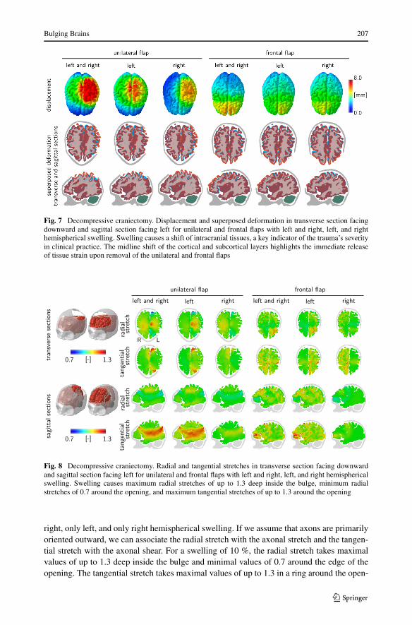
Figure 7 illustrates the displacement and the superposed deformation in transverse sec-tions facing downward and in sagittal sections facing left for unilateral and frontal flaps withboth left and right, only left, and only right hemispherical swelling. The surgical area avail-able for a frontal flap is about twice as large as the area for a unilateral flap. Consequently, forthe same amount of swelling, the displacements of the frontal flap are significantly smallerthan for the unilateral flap. This finding is in agreement with our intuition and with our ide-alized hemidisk simulation in Fig. 3, for which larger opening angles generate smaller radialand tangential stretches. The superposed deformation in transverse and sagittal sections inFig. 7 highlights the relative motion of different regions of the brain as the brain bulges out-ward. Swelling naturally causes a shift of all intracranial tissues. The shift of the midline,which is clearly visible in this sequence of images, is a key clinical indicator for the degreeof trauma.
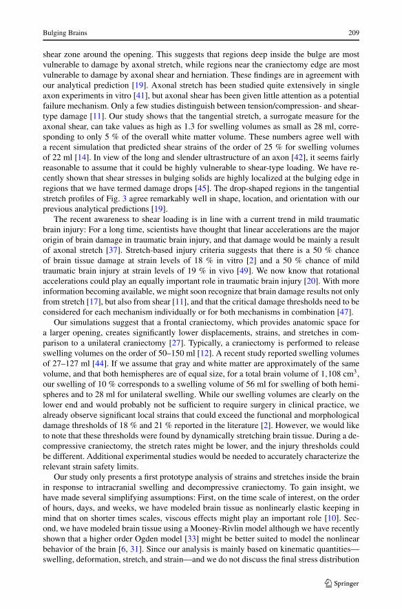
Figure 8 illustrates the radial and tangential stretches in transverse sections facing down-ward and in sagittal sections facing left for unilateral and frontal flaps with both left and
Bulging Brains 207
Fig. 7 Decompressive craniectomy. Displacement and superposed deformation in transverse section facingdownward and sagittal section facing left for unilateral and frontal flaps with left and right, left, and righthemispherical swelling. Swelling causes a shift of intracranial tissues, a key indicator of the trauma’s severityin clinical practice. The midline shift of the cortical and subcortical layers highlights the immediate releaseof tissue strain upon removal of the unilateral and frontal flaps
Fig. 8 Decompressive craniectomy. Radial and tangential stretches in transverse section facing downwardand sagittal section facing left for unilateral and frontal flaps with left and right, left, and right hemisphericalswelling. Swelling causes maximum radial stretches of up to 1.3 deep inside the bulge, minimum radialstretches of 0.7 around the opening, and maximum tangential stretches of up to 1.3 around the opening
right, only left, and only right hemispherical swelling. If we assume that axons are primarilyoriented outward, we can associate the radial stretch with the axonal stretch and the tangen-tial stretch with the axonal shear. For a swelling of 10 %, the radial stretch takes maximalvalues of up to 1.3 deep inside the bulge and minimal values of 0.7 around the edge of theopening. The tangential stretch takes maximal values of up to 1.3 in a ring around the open-

208 J. Weickenmeier et al.
Fig. 9 Decompressive craniectomy. Displacement, maximum principal strain, radial stretch, and tangentialstretch for unilateral and frontal flaps with left and right, left, and right hemispherical swelling. Swellingcauses maximum principal strains of up to 30 % localized around the opening, maximum radial stretches ofup to 1.3 deep inside the bulge, minimum radial stretches of 0.7 around the opening, and maximum tangentialstretches of up to 1.3 around the opening
ing. These three regions might be associated with potential zones of herniation and axonalfailure, either by tension or compression, or by shear.
Figure 9 illustrates the displacement, maximum principal strain, radial stretch, and tan-gential stretch for unilateral and frontal flaps with both left and right, only left, and onlyright hemispherical swelling. The displacement field confirms that the deformation is largerfor the unilateral flap than for the frontal flap. Naturally, the displacements are largest inthe center of the bulge, which explains the large radial strains in the bulge region. In agree-ment with Fig. 8, the radial stretch takes maximum values of 1.3 deep inside the bulge andminimum values of 0.7 around the opening. Similarly, the tangential stretch takes maximumvalues of 1.3 in a ring around the opening.
5 Discussion
Decompressive craniectomy is an invasive neurosurgical procedure to release elevated pres-sures in a swollen brain. Although the technique is highly controversial, it is often performedas a method of last resort; yet, little is known about how the opening of the skull affects thestrain and stress fields inside the brain. Here we introduce a computational model to explorethe effects of decompressive craniectomy in idealized and personalized geometries. Througha systematic analysis of different sets of simulations, we identify several common featuresand trends that could help make the overall procedure less invasive.
In all cases, a unified stretch pattern with three extreme stretch regions emerges: a tensilezone deep inside the bulge, a highly localized compressive zone around the opening, and a
Bulging Brains 209
shear zone around the opening. This suggests that regions deep inside the bulge are mostvulnerable to damage by axonal stretch, while regions near the craniectomy edge are mostvulnerable to damage by axonal shear and herniation. These findings are in agreement withour analytical prediction [19]. Axonal stretch has been studied quite extensively in singleaxon experiments in vitro [41], but axonal shear has been given little attention as a potentialfailure mechanism. Only a few studies distinguish between tension/compression- and shear-type damage [11]. Our study shows that the tangential stretch, a surrogate measure for theaxonal shear, can take values as high as 1.3 for swelling volumes as small as 28 ml, corre-sponding to only 5 % of the overall white matter volume. These numbers agree well witha recent simulation that predicted shear strains of the order of 25 % for swelling volumesof 22 ml [14]. In view of the long and slender ultrastructure of an axon [42], it seems fairlyreasonable to assume that it could be highly vulnerable to shear-type loading. We have re-cently shown that shear stresses in bulging solids are highly localized at the bulging edge inregions that we have termed damage drops [45]. The drop-shaped regions in the tangentialstretch profiles of Fig. 3 agree remarkably well in shape, location, and orientation with ourprevious analytical predictions [19].
The recent awareness to shear loading is in line with a current trend in mild traumaticbrain injury: For a long time, scientists have thought that linear accelerations are the majororigin of brain damage in traumatic brain injury, and that damage would be mainly a resultof axonal stretch [37]. Stretch-based injury criteria suggests that there is a 50 % chanceof brain tissue damage at strain levels of 18 % in vitro [2] and a 50 % chance of mildtraumatic brain injury at strain levels of 19 % in vivo [49]. We now know that rotationalaccelerations could play an equally important role in traumatic brain injury [20]. With moreinformation becoming available, we might soon recognize that brain damage results not onlyfrom stretch [17], but also from shear [11], and that the critical damage thresholds need to beconsidered for each mechanism individually or for both mechanisms in combination [47].
Our simulations suggest that a frontal craniectomy, which provides anatomic space fora larger opening, creates significantly lower displacements, strains, and stretches in com-parison to a unilateral craniectomy [27]. Typically, a craniectomy is performed to releaseswelling volumes on the order of 50–150 ml [12]. A recent study reported swelling volumesof 27–127 ml [44]. If we assume that gray and white matter are approximately of the samevolume, and that both hemispheres are of equal size, for a total brain volume of 1,108 cm3,our swelling of 10 % corresponds to a swelling volume of 56 ml for swelling of both hemi-spheres and to 28 ml for unilateral swelling. While our swelling volumes are clearly on thelower end and would probably not be sufficient to require surgery in clinical practice, wealready observe significant local strains that could exceed the functional and morphologicaldamage thresholds of 18 % and 21 % reported in the literature [2]. However, we would liketo note that these thresholds were found by dynamically stretching brain tissue. During a de-compressive craniectomy, the stretch rates might be lower, and the injury thresholds couldbe different. Additional experimental studies would be needed to accurately characterize therelevant strain safety limits.
Our study only presents a first prototype analysis of strains and stretches inside the brainin response to intracranial swelling and decompressive craniectomy. To gain insight, wehave made several simplifying assumptions: First, on the time scale of interest, on the orderof hours, days, and weeks, we have modeled brain tissue as nonlinearly elastic keeping inmind that on shorter times scales, viscous effects might play an important role [10]. Sec-ond, we have modeled brain tissue using a Mooney-Rivlin model although we have recentlyshown that a higher order Ogden model [33] might be better suited to model the nonlinearbehavior of the brain [6, 31]. Since our analysis is mainly based on kinematic quantities—swelling, deformation, stretch, and strain—and we do not discuss the final stress distribution

210 J. Weickenmeier et al.
in the bulging brain, we believe this is a reasonable first assumption, although a four- or six-parameter Ogden model would more accurately capture the characteristic shear stiffening ofbrain tissue [34]. Third, while recent experiments suggest that the elastic response of braintissues may reasonably well be approximated as isotropic [47], the damage response couldvery well be anisotropic with different failure mechanisms and different damage thresholdsassociated with axonal tension and axonal shear [7]. Fourth, for simplicity, we have as-sumed that all axons point radially outward. A more realistic model would take into accountthe discrete axonal orientation at each individual point of the brain [30]. Conceptually, ouranalysis itself would remain the same; yet, the post-processing to calculate the normal andshear stretches would use the true axonal direction n from diffusion tensor images ratherthan the simplified assumption that n points radially outward.
6 Conclusion
Taken together, our study of bulging brains illustrates how swelling-induced deformationspropagate across the brain when opening the skull. It underlines the notion that a decompres-sive craniectomy is a highly invasive surgical procedure that releases an elevated intracranialpressure at the expense of inducing local zones of extreme strain and stretch. Mathematicalmodels and computational simulations can help identify regions of extreme tissue kine-matics. This approach could guide neurosurgeons to optimize the shape and position of thecraniectomy with the goal to avoid placing the craniectomy edge near functionally importantregions of the brain.
Acknowledgements We thank Allan L. Reiss and his group for providing the MRI scans. This work wassupported by the Timoshenko Scholar Award to Alain Goriely and by the Humboldt Research Award and theNational Institutes of Health grant U01 HL119578 to Ellen Kuhl.
References
1. Abaqus 6.14. Analysis user’s manual. SIMULIA. Dassault Systèmes (2014)2. Bain, A.C., Meaney, D.F.: Tissue-level thresholds for axonal damage in an experimental model of central
nervous system white matter injury. J. Biomech. Eng. 122, 615–622 (2000)3. Barber, J.R.: The solution of elasticity problems for the half-space by the method of Green and Collins.
Appl. Sci. Res. 40, 135–157 (1983)4. Brauna, J., Guob, J., Lutzkendorf, R., Stadler, J., Papazoglou, S., Hirsch, S., Sack, I., Bernarding, J.:
High-resolution mechanical imaging of the human brain by three-dimensional multifrequency magneticresonance elastography at 7T. NeuroImage 90, 308–314 (2014)
5. Budday, S., Nay, R., de Rooij, R., Steinmann, P., Wyrobek, T., Ovaert, O.C., Kuhl, E.: Mechanicalproperties of gray and white matter brain tissue by indentation. J. Mech. Behav. Biomed. Mater. 46,318–330 (2015)
6. Budday, S., Sommer, G., Birkl, C., Langkammer, C., Haybäck, J., Kohnert, J., Bauer, M., Paulsen,F., Steinmann, P., Kuhl, E., Holzapfel, G.: Mechanical characterization of human brain tissue. ActaBiomater. (2017), accepted for publication
7. Cloots, R.J.H., van Dommelen, J.A.W., Nyberg, T., Kleiven, S., Geers, M.G.D.: Micromechanics ofdiffuse axonal injury: influence of axonal orientation and anisotropy. Biomech. Model. Mechanobiol.10, 413–422 (2011)
8. Cooper, D.J., Rosenfeld, J.V., Murray, L., Arabi, Y.M., Davies, A.R., D’Urso, P., Kossmann, T., Pons-ford, J., Seppelt, I., Reilly, P., Wolfe, R.: Decompressive craniectomy in diffuse traumatic brain injury.N. Engl. J. Med. 364, 1493–1502 (2011)
9. Cotton, R.T., Pearce, C.W., Young, P.G., Kota, N., Leung, A.C., Bagchi, A., Qidwai, S.M.: Developmentof a geometrically accurate and adaptable finite element head model for impact simulation: the navalresearch laboratory-simpleware head model. Comput. Methods Biomech. Biomed. Eng. 19, 101–113(2016)

Bulging Brains 211
10. de Rooij, R., Kuhl, E.: Constitutive modeling of brain tissue: current perspectives. Appl. Mech. Rev. 68,010801 (2016)
11. ElSayed, T., Mota, A., Fraternali, F., Ortiz, M.: Biomechanics of traumatic brain injury. Comput. Meth-ods Appl. Mech. Eng. 197, 4692–4701 (2008)
12. Fletcher, T.L., Kolias, A.G., Hutchinson, P.J.A., Sutcliffe, M.P.F.: Development of a finite element modelof decompressive craniectomy. PLoS ONE 9, e102131 (2014)
13. Fletcher, T.L., Kolias, A.G., Hutchinson, P.J.A., Sutcliffe, M.P.F.: An improved method for assessingbrain deformation after decompressive craniectomy. PLoS ONE 9, e110408 (2014)
14. Fletcher, T.L., Kolias, A.G., Adams, H., Hutchinson, P.J.A., Sutcliffe, M.P.F.: Modelling of brain defor-mation after decompressive craniectomy. Ann. Biomed. Eng. (2016). doi:10.1007/s10439-016-1667-7
15. Franceschini, G., Bigoni, D., Regitnig, P., Holzapfel, G.A.: Brain tissue deforms similarly to filled elas-tomers and follows consolidation theory. J. Mech. Phys. Solids 54, 2592–2620 (2006)
16. Gao, C.P., Ang, B.T.: Biomechanical modeling of decompressive craniectomy in traumatic brain injury.Acta Neurochir., Suppl. 102, 279–282 (2008)
17. Goriely, A., Budday, S., Kuhl, E.: Neuromechanics: from neurons to brain. Adv. Appl. Mech. 48, 79–139(2015)
18. Goriely, A., Geers, M.G.D., Holzapfel, G.A., Jayamohan, J., Jerusalem, A., Sivaloganathan, S., Squier,W., van Dommelen, J.A.W., Waters, S., Kuhl, E.: Mechanics of the brain: perspectives, challenges, andopportunities. Biomech. Model. Mechanobiol. 14, 931–965 (2015)
19. Goriely, A., Weickenmeier, J., Kuhl, E.: Stress singularities in swelling soft solids. Phys. Rev. Lett. 117,138001 (2016)
20. Hernandez, F., Wu, L.C., Yip, M.C., Laksari, K., Hoffmann, A.R., Lopez, J.R., Grant, G.A., Kleiven,S., Camarillo, D.B.: Six degree-of-freedom measurements of human mild traumatic brain injury. Ann.Biomed. Eng. 43, 1918–1934 (2015)
21. Hernandez, F., Giordano, C., Kleiven, S., Camarillo, D.B.: Coronal head rotation, falx cerebri displace-ment, and corpus callosum strain are related and implicated in sport-related MTBI. J. Neurotrauma 33,A34–A35 (2016)
22. Holzapfel, G.A.: Nonlinear Solid Mechanics: A Continuum Approach for Engineering. John Wiley &Sons, New York (2000)
23. Hutchinson, P.J., Corteen, E., Czosnyka, M., Mendelow, A.D., Menon, D.K., Mitchell, P., Murray, G.,Pickard, J.D., Rickels, E., Sahuquillo, J., Servadei, F., Teasdale, G.M., Timofeev, I., Unterberg, A., Kirk-patrick, P.J.: Decompressive craniectomy in traumatic brain injury: the randomized multicenter RES-CUEicp study. Acta Neurochir., Suppl. 96, 17–20 (2006)
24. Johnson, K.L.: Contact Mechanics. Cambridge University Press, Cambridge (1987)25. Jones, H.R., Burns, T.M., Aminoff, M.J., Pomeroy, S.L.: Netter Collection of Medical Illustrations:
Nervous System: Part I, Brain, vol. 7. Saunders Elsevier, Philadelphia (2013)26. Kaster, T., Sack, I., Samani, A.: Measurement of the hyperelastic properties of ex vivo brain tissue slices.
J. Biomech. 44, 1158–1163 (2011)27. Kolias, A.G., Kirkpatrick, P.J., Hutchinson, P.: Decompressive craniectomy: past, present and future.
Nat. Rev. Neurol. 9, 405–415 (2013)28. Kruse, S.A., Rose, G.H., Glaser, K.J., Manduca, A., Felmlee, J.P., Jack, C.R., Ehman, R.L.: Magnetic
resonance elastography of the brain. NeuroImage 39, 231–237 (2008)29. Lang, G., Stewart, P.S., Vella, D., Waters, S.L., Goriely, A.: Is the Donnan effect sufficient to explain
swelling in brain tissue slices? J. R. Soc. Interface 11, 20140123 (2014)30. Li, X., van Holst, H., Kleiven, S.: Decompressive craniectomy causes significant strain increase in axonal
fiber tracts. J. Clin. Neurosci. 20, 509–513 (2013)31. Mihai, L.A., Chin, L.K., Janmey, P.A., Goriely, A.: A hyperelastic constitutive model for compression
stiffening applicable to brain and fat tissues. J. R. Soc. Interface 12, 20150486 (2015)32. Mooney, M.: A theory of large elastic deformation. J. Appl. Phys. 11, 582–592 (1940)33. Ogden, R.W.: Large deformation isotropic elasticity – on the correlation of theory and experiment for
incompressible rubberlike solids. Proc. R. Soc. Lond. A 326, 565–584 (1972)34. Pogoda, K., Chin, L.K., Georges, P.C., Byfield, F.R.J., Bucki, R., Kim, R., Weaver, M., Wells, R.G.,
Marcinkiewicz, C., Janmey, P.A.: Compression stiffening of brain and its effect on mechanosensing byglioma cells. New J. Phys. 16, 075002 (2014)
35. Quinn, T.M., Taylor, J.J., Magarik, J.A., Vought, E., Kindy, M.S., Ellegala, D.B.: Decompressive craniec-tomy: technical note. Acta Neurol. Scand. 123, 239–244 (2011)
36. Rivlin, R.S.: Large elastic deformations of isotropic materials. IV. Further developments of the generaltheory. Philos. Trans. R. Soc. Lond. 241, 379–397 (1948)
37. Rowson, S., Duma, S.M., Beckwirth, J.G., Chu, J.J., Greenwald, R.M., Crisco, J.J., Brolinson, P.G.,Duhaime, A.C., McAllister, T.W., Maerlender, A.C.: Rotational head kinematics in football impacts: aninjury risk function for concussion. Ann. Biomed. Eng. 40, 1–13 (2012)

212 J. Weickenmeier et al.
38. Saggar, M., Quintin, E.M., Kienitz, E., Bott, N.T., Sun, Z., Hong, W.C., Chien, Y., Liu, N., Dougherty,R.F., Royalty, A., Hawthorne, G., Reiss, A.L.: Pictionary-based fMRI paradigm to study the neuralcorrelates of spontaneous improvisation and figural creativity. Sci. Rep. 5, 10894 (2015)
39. Stiver, S.I.: Complications of decompressive craniectomy for traumatic brain injury. Neurosurg. Focus26, E7 (2009)
40. Tagliaferri, F., Zani, G., Iaccarino, C., Ferro, S., Ridolfi, L., Basaglia, N., Hutchinson, P., Servadei, F.:Decompressive craniotomies, facts and fiction: a retrospective analysis of 526 cases. Acta Neurochir.154, 916–919 (2012)
41. Tang-Schomer, M.D., Patel, A.R., Baas, P.W., Smith, D.H.: Mechanical breaking of microtubules inaxons during dynamic stretch injury underlies delayed elasticity, microtubule disassembly, and axondegeneration. FASEB J. 24, 1401–1410 (2010)
42. van den Bedem, H., Kuhl, E.: Tau-ism: the Yin and Yang of microtubule sliding, detachment, and rupture.Biophys. J. 109, 2215–2217 (2015)
43. von Holst, H., Li, X.: Decompressive craniectomy (DC) at the non-injured side of the brain has thepotential to improve patient outcome as measured with computational simulation. Acta Neurochir. 156,1961–1967 (2014)
44. von Holst, H., Li, X., Kleiven, S.: Increased strain levels and water content in brain tissue after decom-pressive craniectomy. Acta Neurochir. 154, 1583–1593 (2012)
45. Weickenmeier, J., Kuhl, E., Goriely, A.: The mechanics of decompressive craniectomy: bulging in ide-alized geometries. J. Mech. Phys. Solids 96, 572–590 (2016)
46. Weickenmeier, J., Butler, C., Young, P.G., Goriely, A., Kuhl, E.: The mechanics of decompres-sive craniectomy: personalized simulations. Comput. Methods Appl. Mech. Eng. (2017). doi:10.1016/j.cma.2016.08.011
47. Wright, R.M., Ramesh, K.T.: An axonal strain injury criterion for traumatic brain injury. Biomech.Model. Mechanobiol. 11, 245–260 (2011)
48. Young, P.G., Beresford-West, T.B.H., Coward, S.R.L., Notarberardino, B., Walker, B., Abdul-Aziz, A.:An efficient approach to converting 3D image data into highly accurate computational models. Philos.Trans. R. Soc. Lond. A 366, 3155–3173 (2008)
49. Zhang, L., Yang, K.H., King, A.I.: A proposed injury threshold for mild traumatic brain injury.J. Biomech. Eng. 126, 226–236 (2004)