Embed Size (px)
Citation preview

1
Building Scalable Cisco Internetworks
Module 1 Network Requirements
Lesson 1 Describing Network Requirments
Cisco hierarchical network model: � Access layer � Distribution layer � Core layer (backbone). SAFE: � Enterprise campus � Enterprise edge � Service provider edge. SONA (Cisco Service-Oriented netork Architecture): � Network infrastructure layer � Interactive services layer � Application layer IIN (Intellignet Information Network): � Integrated transport � Integrated services � Integrated applications

2
Module 2 Configuring EIGRP
Lesson 1 Introducing EIGRP
EIGRP capabilities and attributes: (Cisco proprietary protocol) � Fast convergence � Loop free � DUAL (Diffusing Update Algorithm) � VLSM & discontinuous subnetworks support � Partial updates – triggered updates � Multiple network-layer protocol support – IP, AppleTalk, Novel NetWare IPX � Seamless connectivity across all data link layer protocols and topologies � Sophisticated metric – 32 bit � Multicast & unicast – 224.0.0.10 EIGRP Key Technologies: � Neighbor discovery/recovery - hello � Reliable transport protocol (RTP) � DUAL finite-state machine � Protocol-dependent modules (PDMs) Neighbor Table: � List adjacent routers ( topology table –learned routes to each destination, feasible successor route routing table – best route to each destination, successor route best route – successor route feasible successor route – backup route to a destination, in topology table) � Neighbor’s adderss & interface � Neighbor -> hello (hold time) -> no response -> DUAL is informed of the
topology change DUAL � Select loest-cost, loop-free paths � AD (Advertised Distance) = cost <next-hop router - destination> � FD (Feasbible Distance) = cost <local - destination> = AD + cost <local –
netx-hop router> � Lowest-cost = lowest FD � (Current) successor – next-hop router with lowest-cost, loop-free path – lowest
FD � Feasible successor – backup router with loop-free path
(AD of feasible successor < FD of current successor route) � Default 4 successors can be added to the routing table. Max 6 Topology Table:

3
� Contain all destinations advertised by neighboring routiers � Maintains the metric that each neighbor advettises for each destination (AD) &
the metric that this router would use to reach the destination via that neighbor (FD)
� Changed when a directly connected route or interface changes or when a neighobring router reports a change to a route
� Two states: active / passive � Active: the router is performing a recomputation � Passive: the router is not performing a recomputation (desired state) Routing Table: � The lowest FD – successor router EIGRP Packets: � Hello: neighbor discovery – multicasts, no acknowledgement requirement � Update: unicast to specific router or multicast to multiple router

4
� Query: ask for feasible successor – multicast but can be retransmitted as unicast � Reply: unicast � ACK: for update, query and reply – unicast hello packets and contain a nonzero
acknowledge number EIGRP Metric: (bandwidth & delay by default. 256 * IGRP metric) � Bandwidth: smallest bandwidth between source and destination � Delay: cumulative interface delay along the path � Reliability: worst reliability between source and destination, based on keepalives � Loading: worst load on a link between source and destination � MTU: (Maximum Transmission Unit) smallest MTU in the path EIGRP Metric Calculation: � Default : K1=K3=1, K2=K4=K5=0 � Default: Metric = bandwidth (slowest link)+ delay (sum of delay) � Metric = (K1*bandwidth) + [(K2*bandwidth)/(256-load)] + (K3*delay) � If K5 not equal to 0 Metric = Metric * [K5/(reliability + K4)] � Delay: sume of delay in the path, in 10ms, multiplied by 256 � Bandwidth = [10^7 / (minimum bandwidth link along the path, in kbps)] * 256 � K values are carried in EIGRP hello packets. Integrating the EIGRP & IGRP Routes � EIGRP: 32 bit; IGRP: 24 bit � EIGRP metric = IGRP metric * 256

5
Lesson 2 Implementing and Verifying EIGRP
Configuring Basic EIGRP: � R(config)#router eigrp autonomous-system-number � R(config-router)#network network-number [ wildcard-mask] � R(config-if)#bandwidth kilobits (default T1)
- NOTE: EIGRP automatically summarizes routes on the major netowork boundary
EIGRP Default Route: � R(config)#ip default-network netowork-number
Verify EIGRP IP Routes and IP Operations: � R#show ip eigrp neighbors
� R#show ip router eigrp
R1#show ip eigrp neighbors
IP-EIGRP neighbors for process 100
H Address Interface Hold Uptime SRT T RTO Q Seq
(sec) (ms) Cnt Num
0 192.168.1.102 Se0/0/1 10 00:07:22 10 2280 0 5
R1#
R1#show ip route eigrp
D 172.17.0.0/16 [90/40514560] via 192.168.1.102, 00:07:01, Serial0/0/1
172.16.0.0/16 is variably subnetted, 2 subnets , 2 masks
D 172.16.0.0/16 is a summary, 00:05:13, Null0
192.168.1.0/24 is variably subnetted, 2 subnet s, 2 masks
D 192.168.1.0/24 is a summary, 00:05:13, Null 0
R1#show ip route
<output omitted>
Gateway of last resort is not set
D 172.17.0.0/16 [90/40514560] via 192.168.1.102, 00:06:55, Serial0/0/1
172.16.0.0/16 is variably subnetted, 2 subnets , 2 masks
D 172.16.0.0/16 is a summary, 00:05:07, Null0
C 172.16.1.0/24 is directly connected, FastEt hernet0/0
192.168.1.0/24 is variably subnetted, 2 subnet s, 2 masks
C 192.168.1.96/27 is directly connected, Seri al0/0/1
D 192.168.1.0/24 is a summary, 00:05:07, Null 0
6
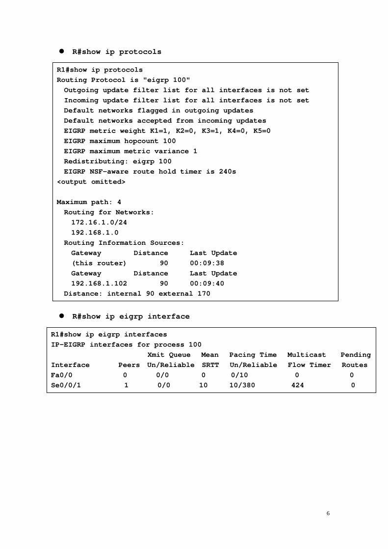
� R#show ip protocols
� R#show ip eigrp interface
R1#show ip protocols
Routing Protocol is "eigrp 100"
Outgoing update filter list for all interfaces is not set
Incoming update filter list for all interfaces is not set
Default networks flagged in outgoing updates
Default networks accepted from incoming updates
EIGRP metric weight K1=1, K2=0, K3=1, K4=0, K5=0
EIGRP maximum hopcount 100
EIGRP maximum metric variance 1
Redistributing: eigrp 100
EIGRP NSF-aware route hold timer is 240s
<output omitted>
Maximum path: 4
Routing for Networks:
172.16.1.0/24
192.168.1.0
Routing Information Sources:
Gateway Distance Last Update
(this router) 90 00:09:38
Gateway Distance Last Update
192.168.1.102 90 00:09:40
Distance: internal 90 external 170
R1#show ip eigrp interfaces
IP-EIGRP interfaces for process 100
Xmit Queue Mean Paci ng Time Multicast Pending
Interface Peers Un/Reliable SRTT Un/Reli able Flow Timer Routes
Fa0/0 0 0/0 0 0/1 0 0 0
Se0/0/1 1 0/0 10 10/3 80 424 0

7
� R#show ip eigrp topology
� R#show ip eigrp trafic
R1#show ip eigrp topology
IP-EIGRP Topology Table for AS(100)/ID(192.168.1.10 1)
Codes: P - Passive, A - Active, U - Update, Q - Que ry, R - Reply,
r - reply Status, s - sia Status
P 192.168.1.96/27, 1 successors, FD is 40512000
via Connected, Serial0/0/1
P 192.168.1.0/24, 1 successors, FD is 40512000
via Summary (40512000/0), Null0
P 172.16.0.0/16, 1 successors, FD is 28160
via Summary (28160/0), Null0
P 172.16.1.0/24, 1 successors, FD is 28160
via Connected, FastEthernet0/0
P 172.17.0.0/16, 1 successors, FD is 40514560
via 192.168.1.102 (40514560/28160), Serial0 /0/1
R1#show ip eigrp traffic
IP-EIGRP Traffic Statistics for AS 100
Hellos sent/received: 429/192
Updates sent/received: 4/4
Queries sent/received: 1/0
Replies sent/received: 0/1
Acks sent/received: 4/3
Input queue high water mark 1, 0 drops
SIA-Queries sent/received: 0/0
SIA-Replies sent/received: 0/0
Hello Process ID: 113
PDM Process ID: 73

8
Lesson 3 Confirguring Advanced EIGRP Options
Automatic summarization: default - enable Manual summarization: � When the last specific route of summary goes away, the summary is deleted � Metric: minimum � Summary routes to interface null0 � R(config-router)#no auto-summary � R(config-if)#ip summary-address eigrp as-number address
mask [ admin-distance]
Load Balancing Across Equal Paths: � Default – 4; Max – 6 (command: maximum-paths maximum-path) � maximum-path = 1 – disable load balancing � fast-switched – on a per-packet basis Load Balancing Across Unequal-Cost Paths: � R(config-router)#variance multiplie
� Two feasiblity conditions: 1. the loacl best metric (the current FD) > the best metric (AD) learned from the next router. 2. multiplie * the current FD > the metric throught the next route (alternative FD)
EIGRP Bandwidth Use Across WAN Links � Support : point-to-point links
Nonboradcast Multiacess (NBMA): point-to-point links Multipoint links
� Default - 50% bandwidth � command: bandwidth
ip bandwidth-percent eigrp as-number percent (percent can be greater than 100) Bandwidth Utilization over WAN Interfaces � Point-to-point subinterfaces using Frame Relay:
- T1 by default - manually configure bandwidth to match the contracted committed information rate (CIR) of the permanent virtual circuit (PVC). � Multipoint Frame Relay, ATM, ISDN PRI:
- all neighbors share the bandwidth equally - EIGRP uses the bandwidth on the physical interface divided by the number of neighbors on that interface to calculate the bandwidth attributed per neighbor � Each PVC can have a different CIR, creating an EIGRP packet-pacing problem � Multipoint intervace – convert these to point-to-point configuration or manually
configure bandwidth by multiplying the lowest CIR by the number of PVCs

9
EIGRP WAN Configuration: � Frame Relay Hub-and-Spoke Topology
- configure each virtual Circuit as point-to-point, specify bandwidth = 1/10 of link capacity - increase EIGRP utilization to 50% of actual VC capacity
� Hybrid Multipoint - Configure lowest CIR vitual circuit as point-to-point, specify bandwidth = CIR - Configure higher CIR vitual circuits as multipoint, combine CIRS

10
Lesson 4 Confirguring EIGRP Authentication
Route Authentication � Simple password (plain-text): IS-IS, OSPF, RIPv2 � MD5: OSPF, RIPv2, BGP, EIGRP EIGRP MD5 Authentication � Router generates and checks every packet. Router authenticates the source of
each routing update packet that it receives. � Configure a key (password) and key ID on both the sending and the receiving
router; each participating neighbor must have same key configured. � Rotuer generates a message digest, or hash, of the key, key ID, and message � EIGRP allows keys to be managed using key chains � Specify key ID (number), key, and lifetime of key. (key activation times overlap
to avoid any period of time for which no key is activated.) � Fisrt valid actived key, in order of key numbers, is used Configuring MD5 Authentication � R(config-if)#ip authentication mode eigrp
autonomous-systme md5
� R(config-if)#ip authentication key-chain eigrp autonomous-systme name-of-chain
� R(config)#key chain name-of-chain � R(config-keychain)#key key-id � R(config-keychain-key)#key-string text � R(config-keychain-key)#accept-lifetime start-time
{infinite | end-time | duration seconds} � R(config-keychain-key)#send-lifetime start-time
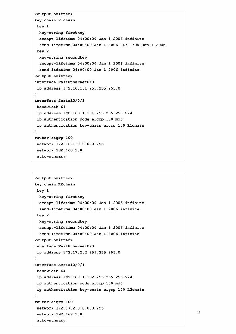
{infinite | end-time | duration seconds} Troubleshooting MD5 Authentication � R#debug eigrp packets Example:
11
<output omitted>
key chain R1chain
key 1
key-string firstkey
accept-lifetime 04:00:00 Jan 1 2006 infinite
send-lifetime 04:00:00 Jan 1 2006 04:01:00 Jan 1 2006
key 2
key-string secondkey
accept-lifetime 04:00:00 Jan 1 2006 infinite
send-lifetime 04:00:00 Jan 1 2006 infinite
<output omitted>
interface FastEthernet0/0
ip address 172.16.1.1 255.255.255.0
!
interface Serial0/0/1
bandwidth 64
ip address 192.168.1.101 255.255.255.224
ip authentication mode eigrp 100 md5
ip authentication key-chain eigrp 100 R1chain
!
router eigrp 100
network 172.16.1.0 0.0.0.255
network 192.168.1.0
auto-summary
<output omitted>
key chain R2chain
key 1
key-string firstkey
accept-lifetime 04:00:00 Jan 1 2006 infinite
send-lifetime 04:00:00 Jan 1 2006 infinite
key 2
key-string secondkey
accept-lifetime 04:00:00 Jan 1 2006 infinite
send-lifetime 04:00:00 Jan 1 2006 infinite
<output omitted>
interface FastEthernet0/0
ip address 172.17.2.2 255.255.255.0
!
interface Serial0/0/1
bandwidth 64
ip address 192.168.1.102 255.255.255.224
ip authentication mode eigrp 100 md5
ip authentication key-chain eigrp 100 R2chain
!
router eigrp 100
network 172.17.2.0 0.0.0.255
network 192.168.1.0
auto-summary

12
Lesson 5 Using EIGRP in an Enterprise Network
Factors that Influence EIGRP Scalability � Quantity of routing information exchanged between neighbors; without proper
route summarization, this can be excessive � Number of routers that must be invlved when a topoloy change occurs � Depth of topology: the number of hops that information must travel to reach all
routers � Number of alternate paths rhrouth the network. (stuck in active (SIA)) EIGRP Query Process � Queries are sent when a route is lost and no feasible successor is available � The lost route is now in active state � Queries are sent to all neighboring routers on all interfaces except the interface to
the successor � If the neighbors do not have the lost-route information, queries aer sent to their
neighbors � If a router has an alternate route, it answers the qurey; this stops the query form
speading in that branch of the network EIGRP Stub � The EIGRP stub routing feature improves network stability, reduces resource
utilization, and simplifies remote router (spoke) configuration. � Stub routing is commonly used in a hub-and-spoke topology. � A stub router sends a special peer information packet to all neighboring routers to
report its status as a stub router. � A neighbor that receives a packet informing it of the stub status does not query
the stub router for any routes. Configuring EIGRP Stub � R(config-router)#eigrp stub [receive-only | connected |
static | summary] - receive-only : Prevent the stub from sending any type of route. - connected : Permits stub to send connected routes (may still need to redistribute) (command: redistribute connected ). - static : Permits stub to send static routes (must still redistribute) (command: redistribute static ). - summary : Permits stub to send summary routes. (command: ip summary-address or auto-summary ) - Default - connected and summary
Limiting Updates and Queries: Using EIGRP Stub � R(config)#router eigrp 1 � R(config-router)#eigrp stub

13
Example: eigrp stub Parameters � If stub connected is configured:
- B will advertise 10.1.2.0/24 to A. - B will not advertise 10.1.2.0/23, 10.1.3.0/23, or 10.1.4.0/24. � If stub summary is configured:
- B will advertise 10.1.2.0/23 to A. - B will not advertise 10.1.2.0/24, 10.1.3.0/24, or 10.1.4.0/24.
� If stub static is configured:
- B will advertise 10.1.4.0/24 to A. - B will not advertise 10.1.2.0/24, 10.1.2.0/23, or 10.1.3.0/24. � If stub receive-only is configured:
- B will not advertise anything to A, so A needs to have a static route to the networks behind B to reach them.

14
SIA Connections: (Stuck in Active) � The router has to get all replies form the neighbors with an outstanding query
before the router calculates the successor information � If any neighbor fails to reply to the query within 3 minutes by default, the route is
SIA, and the router resets the neighbor relationship with the neighbor that fails to reply.
Most Common Reasons for SIA Routes: � The router is too busy to answer the query – high CPU, membory problems � The link between the two routers is not good – some packets are lost � A failure causes traffic on a link to flow in only one direction – unidirectional link Preventing SIA Connections: Graceful Shutdown � Goodbye message is broadcast when an EIGRP ruting process is shut down, to
inform adjacent peers about the impending topology change.
� Before Router A resets relationship to router B when the normal active timer expires. However, the problem is the link between router B and C.
� After Router A sends an SIA-Query at half of the normal active timer. Router B acknowledges the query there by keeping the relationship up.

15
Module 3 Configuring OSPF
Lesson 1 Introducing the OSPF Protocol
Linkstate Routing Protocols � Respond quickly to network changes � Send triggered updates when a network change occurs � Send periodic updates, known as link-state refresh, at long intervals, such as
every 30 minutes � LSA (link-state advertisement) -> multicast -> LSDB (link-state database)
updated -> forwards LSA to their neighbors: LSA flooding ensures that all routing devices update their database befor updating routing tables to reflect the new topology.
� LSDB is used to calculate the bes paths through the network. – apply Dijkstra’s algorithm (SPF) to build the SPF tree. – the best paths are selected from the SPF tree and placed in the routing table.
Link-State Data Structures � Each router independently calculates its best paths to all destinations in the
network. Each router maintains its own view of the network. � Neighbor table:
- Adjacency database - Contains list of recognized neighbors � Toploogy table:
- Typically referred to as LSDB - Contains all routers and their attached links in the area or network - Identical LSDB for all routers within an area � Routing table:
- Commonly named a forwarding databae - Contains list of best paths to destinations
Link-State Routing Protocols � Link-state routers recognize more information about the network than their
distance vector counterparts � Each router has a full picture of the topology � Consequently, link-state routers tend to make more accurate decisions Network hierarchy � Transit area (backbone or area0) � Regular areas (nonbackbone areas) OSPF Areas: � Minimizes routing table entries � Localizes impact of a topology change within an area

16
� Detailed LSA flooding stops at the area boundary � Requires a hierarchical network design Area Terminology � Backbone router: router that make up area 0 � ABR (area border router): connect area 0 to the nonbackbone areas
- Separate LSA flooding zones - Primar point for area address summarization - Function regualrly as the source for defualt routes - Maintain the LSDB for each area with which it is connected
OSPF Adjacencies: � Multicast – send and receive hello packets to and from neighboring routers � Exchange hello packets subject to protocol-specific parameters � After neighbor adjacency esablished, synchronize their LSDBs by exchanging
LSAs and confirming the receipt of LSAs from the adjacent router. For OSPF, the routers are now in full adjacnecy state with each other.
� If necessory, new LSAs to other neighboring routers Forming OSPF Adjacencies � Point-to-point WAN: High-Level Data Link Control (HDLC) or PPP � LAN links:
- Neighbors form a full adjacency with DR (designated router) BDR (backup designated router) - Routers maintain two-way state with the other routers (DROTHERs) � Routing updates and topology information are passed only between adjacent
routers � Once an adjacency is formed, LSDBs are synchronized by exchanging LSAs � LSAs are flooded reliably throughout the area (or network). OSPF Calculation � Every router in an area has the identical link-state database � Each router in the are places itself into the root of the tree that is built � The best path is calculated with respect to the lowest total cost of links to a
specific destination � Best routes are put into the forwarding database (routing table)

17
LSA OperationL using LSUs (link-state updates), can contain one or more LSAs

18
Lesson 2 OSPF Packet Types
OSPF Packet Types � Hello: discovers neighbors and builds adjacencies between them � DBD (Database Description): checks for database synchronization between
routers � LSR (Link-State Request): requests specific link-state records from router to
router � LSU (Link-State Update): sends specifically requested lin-state records � LSAck (Link-State Acknowldgement): Acknowledges the other packet types OSPF Packet Header Format Establishing OSPF Neighbor Adjacencies � Multicast 224.0.0.5 to send hello packets periodically

19
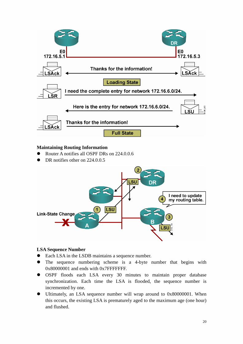
Exchanging and Synchronizing LSDBs Discovering the Network Routes
20
Maintaining Routing Information � Router A notifies all OSPF DRs on 224.0.0.6 � DR notifies other on 224.0.0.5 LSA Sequence Number � Each LSA in the LSDB maintains a sequence number. � The sequence numbering scheme is a 4-byte number that begins with
0x80000001 and ends with 0x7FFFFFFF. � OSPF floods each LSA every 30 minutes to maintain proper database
synchronization. Each time the LSA is flooded, the sequence number is incremented by one.
� Ultimately, an LSA sequence number will wrap around to 0x80000001. When this occurs, the existing LSA is prematurely aged to the maximum age (one hour) and flushed.

21
� When a router encounters two instances of an LSA, it must determine which is more recent. The LSA having the newer (higher) LS a sequence number is more recent.
LSA Sequence Numbers and Maximum Age � Every OSPF router announces a router LSA for those interfaces that it owns in
that area. � Router with link ID 192.168.1.67 has been updated eight times; the last update
was 48 seconds ago. Debug ip ospf packet
� v – OSPF version � t – 1: hello; 2: DBD; 3: LSR; 4: LSU; 5: LSAck � l – OSPF packet length in bytes � rid – OSPF router ID � aid – OSPF area ID � chk – OSPF checksum � aut – 0: no authentication; 1: simple password; 2: MD5 � auk – OSPF authentication key, if used � keyid – MD5 key ID, only used for MD5 authentication � swq – sequence number, only used for MD5 authentiation
RTC# show ip ospf database
OSPF Router with ID (192.168.1.67) (P rocess ID 10)
Router Link States (Area 1)
Link ID ADV Router Age Seq# Checksum Lin k count
192.168.1.67 192.168.1.67 48 0x80000008 0xB112 2
192.168.2.130 192.168.2.130 212 0x80000006 0x3F44 2
<output omitted>
R1#debug ip ospf packet
OSPF packet debugging is on
R1#
*Feb 16 11:03:51.206: OSPF: rcv. v:2 t:1 l:48 rid:1 0.0.0.12
aid:0.0.0.1 chk:D882 aut:0 auk: from Serial0/ 0/0.2

22
Lesson 3 Configuring OSPF Routing
Configuring Basic OSPF � R(config)#router ospf process-id [vrf vpn-name] � R(config-router)#network ip-address wildcard-mask area
area-id � R(config-if)#ip ospf process-id area area-id [secondaries
none] Configuring OSPF on Internal Routers of a Single Area Configuring OSPF for Multiple Areas
23
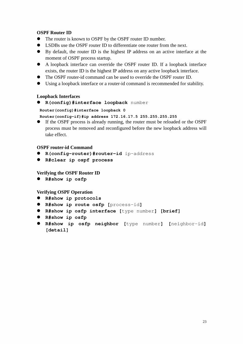
OSPF Router ID � The router is known to OSPF by the OSPF router ID number. � LSDBs use the OSPF router ID to differentiate one router from the next. � By default, the router ID is the highest IP address on an active interface at the
moment of OSPF process startup. � A loopback interface can override the OSPF router ID. If a loopback interface
exists, the router ID is the highest IP address on any active loopback interface. � The OSPF router-id command can be used to override the OSPF router ID. � Using a loopback interface or a router-id command is recommended for stability. Loopback Interfaces � R(config)#interface loopback number � If the OSPF process is already running, the router must be reloaded or the OSPF
process must be removed and reconfigured before the new loopback address will take effect.
OSPF router-id Command � R(config-router)#router-id ip-address � R#clear ip ospf process Verifying the OSPF Router ID � R#show ip osfp Verifying OSPF Operation � R#show ip protocols � R#show ip route osfp [ process-id] � R#show ip osfp interface [ type number] [brief] � R#show ip osfp � R#show ip osfp neighbor [ type number] [ neighbor-id]
[detail]
Router(config)#interface loopback 0
Router(config-if)#ip address 172.16.17.5 255.255.25 5.255

24
Lesson 4 OSPF Network Types
OSPF Network Types � Point-to-point: a netwrok that joins a single pair of routers � Broadcat: a multiaccess broadcast network, such as ethernet � Nonboardcast multiaccess (NBMA): a network that interconnects more than two
routers but that has no boradcast capability. Frame Relay, ATM and X.25 Point-to-Point Links � Usually a serial interface running either PPP or HDLC. � May also be a point-to-point subinterface running Frame Relay or ATM. � No DR or BDR election required. � OSPF autodetects this interface type. � OSPF packets are sent using multicast 224.0.0.5. � Hello :10s; dead: 40s Multiaccess Broadcast Network � Generally these are, LAN technologies like Ethernet and Token Ring. � DR and BDR selection are required. � All neighbor routers form full adjacencies with the DR and BDR only. � Packets to the DR and the BDR use 224.0.0.6. � Packets from DR to all other routers use 224.0.0.5. � BDR does not operate when DR is operating. BDR performs the DR tasks only if
the DR fails. If the DR fails, BDR automaticall becomes the DR and a new BDR election occurs
Electing the DR and BDR � Hello packets are exchanged via IP multicast. � The router with the highest OSPF priority is selected as
the DR. The router with the second-highest priority value is the BDR. � Use the OSPF router ID as the tiebreaker. � The DR election is nonpreemptive. Setting Priority for DR Election � R(config-if)#ip osfp priority number � This interface configuration command assigns the OSPF priority to an interface. � Different interfaces on a router may be assigned different values. � The default priority is 1. The range is from 0 to 255. � 0 means the router cannot be the DR or BDR. � A router that is not the DR or BDR is DROTHER. NBMA Topology � A single interface interconnects multiple sites. � NBMA topologies support multiple routers, but without broadcasting capabilities.
25
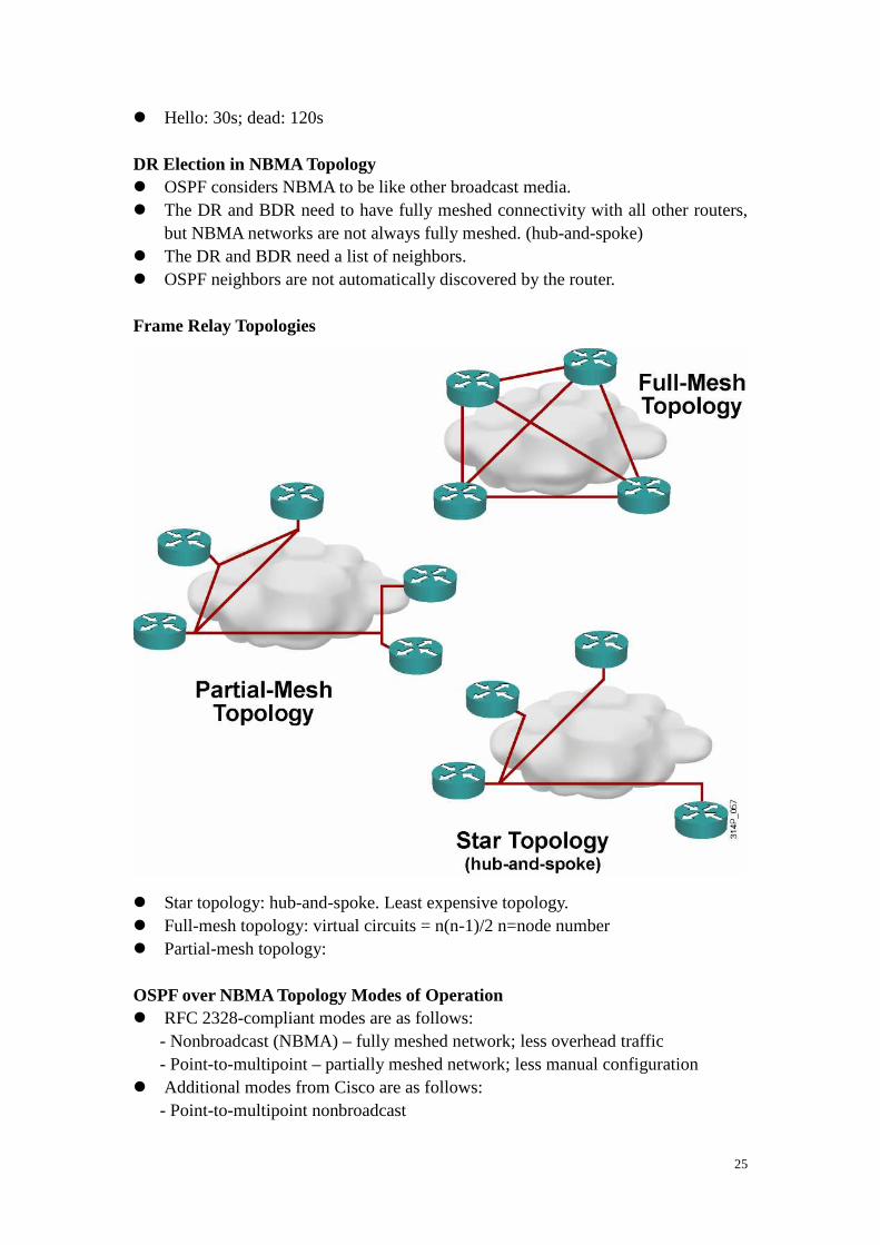
� Hello: 30s; dead: 120s DR Election in NBMA Topology � OSPF considers NBMA to be like other broadcast media. � The DR and BDR need to have fully meshed connectivity with all other routers,
but NBMA networks are not always fully meshed. (hub-and-spoke) � The DR and BDR need a list of neighbors. � OSPF neighbors are not automatically discovered by the router. Frame Relay Topologies � Star topology: hub-and-spoke. Least expensive topology. � Full-mesh topology: virtual circuits = n(n-1)/2 n=node number � Partial-mesh topology: OSPF over NBMA Topology Modes of Operation � RFC 2328-compliant modes are as follows:
- Nonbroadcast (NBMA) – fully meshed network; less overhead traffic - Point-to-multipoint – partially meshed network; less manual configuration � Additional modes from Cisco are as follows:
- Point-to-multipoint nonbroadcast

26
- Broadcast - Point-to-point
Selecting the OSPF Network Type for NBMA Networks � R(config-if)#ip osfp network [{broadcast | non-broadcast
| point-to-multipoint [non-broadcast] | point-to-point}] � Broadcast : cisco extension
- Makes the WAN interface appear to be a LAN - One IP subnet - Uses multicast OSPF hello packet to automatially discover the neighbors - DR and BDR elected - Requires a full-mesh or partial-mesh topology � non-broadcast : RFC-compliant mode
- One IP subnet - Neighbors must be manually configured - DR and BDR elected - DR and BDR need to have full connectivity with all other routers - Typically uses in a full-mesh or partial-mesh topology � point-to-multipoint : RFC-compliant mode
- One IP subnet - Uses multicast OSPF hello packet to automatially discover the neighbors - DR and BDR not required – router sends additional LSAs with more information about neighboring routers - Typically uses in partial-mesh or star topology � point-to-multipoint non-broadcast : cisco extension
- if multicast and broadcast are not enabled on the virtual circuits, the RFC-compliant point-to-multipoint mode cannot be used because the router cannot dynamically discover its neighboring routers using hello multicast packets; the Cisco mode should be used instead - Neighbors must be manually configured - DR and BDR election is not required � point-to-point : cisco extension
- Different IP subnet on each subinterface - No DR or BDR election - Used when only two routers need to form an adjacency on a pair of interfaces - Interfaces can be either LAN or WAN
OSPF over Frame Relay NBMA Configuration � Treated as a broadcast
network by OSPF (acts like a LAN).
� All serial ports are part of the same IP subnet.
� Frame Relay, X.25, and

27
ATM networks default to nonbroadcast mode. � Neighbors must be statically configured. � Duplicates LSA updates. � Complies with RFC 2328 � Routers are usually fully meshed. If not fully meshed, select the DR and BDR
manually to ensure the selected DR and BDR have full connectivity to all other neighboring routers.
Using the neighbor Command � R(config-router)#neighbor ip-address [priority number]
[poll-interval number] [cost number] [database-filter all]
� This command is used to statically define adjanct relationships in NBMA network � ip-address: IP address of neighboring router � priority number: default – 0 – means the neighbor does not become the DR � poll-interval number: time to wait before sending hellos to the neighbor
even if the neighbor is inactive. – in second � cost number: cost to the neighbor. 1-65535. � database-filter all : filters outgoing LSAs to an OSPF neighbor
neighbor Command Example `
show ip ospf neighbor Command � R#show ip ospf neighbor [ type number] [ neighbor-id]
[detail]
RouterA(config)# router ospf 100
RouterA(config-router)# network 192.168.0.0 0.0.255.255 area 0
RouterA(config-router)# neighbor 192.168.1.2 priority 0
RouterA(config-router)# neighbor 192.168.1.3 priority 0
RouterA(config-router)# network 172.16.0.0 0.0.255.255 area 0

28
OSPF over Frame Relay Point-to-Multipoint Configuration � The point-to-multipoint mode allows for NBMA networking. � The point-to-multipoint mode fixes partial-mesh and star topologies. � No DR is required and only a single subnet is used. � A 30-second hello is used. � This mode is RFC 2328-compliant. � In large netowrks, using point-to-multipoint mode reduces the number of PVCs
required for complete connectivity, because not requried to have a full-mesh topology. In addition, no having full-mesh topology reduces the number of neighbor entries in the neighbor table.
� Properties: - Does not require a fully meshed network - Does not require a static neighbor configuration - Uses one IP subnet - Duplicates LSA packets
Point-to-Multipoint Configuration � RouterA � RouterC
RouterA# show ip ospf neighbor
Neighbor ID Pri State Dead Time Add ress Interface
192.168.1.3 0 FULL/DROTHER 00:01:57 192.1 68.1.3 Serial0/0/0
192.168.1.2 0 FULL/DROTHER 00:01:33 192.1 68.1.2 Serial0/0/0
172.16.1.1 1 FULL/BDR 00:00:34 172. 16.1.1 FastEthernet0/0
interface Serial0/0/0
ip address 192.168.1.1 255.255.255.0
encapsulation frame-relay
ip ospf network point-to-multipoint
<output omitted>
router ospf 100
log-adjacency-changes
network 172.16.0.0 0.0.255.255 area 0
network 192.168.0.0 0.0.255.255 area 0
interface Serial0/0/0
ip address 192.168.1.3 255.255.255.0
encapsulation frame-relay
ip ospf network point-to-multipoint
ip ospf priority 0
29
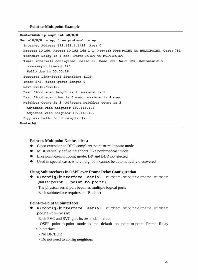
Point-to-Multipoint Example Point-to-Multipoint Nonbroadcast � Cisco extension to RFC-compliant point-to-multipoint mode � Must statically define neighbors, like nonbroadcast mode � Like point-to-multipoint mode, DR and BDR not elected � Used in special cases where neighbors cannot be automatically discovered Using Subinterfaces in OSPF over Frame Relay Configuration � R(config)#interface serial number.subinterface-number
{multipoint | point-to-point} - The physical serial port becomes multiple logical ports - Each subinterface requires an IP subnet
Point-to-Point Subinterfaces � R(config)#interface serial number.subinterface-number
point-to-point - Each PVC and SVC gets its own subinterface - OSPF point-to-point mode is the default on point-to-point Frame Relay subinterface.
- No DR/BDR - Do not need to config neighbors
RouterA#sh ip ospf int s0/0/0
Serial0/0/0 is up, line protocol is up
Internet Address 192.168.1.1/24, Area 0
Process ID 100, Router ID 192.168.1.1, Network Ty pe POINT_TO_MULTIPOINT, Cost: 781
Transmit Delay is 1 sec, State POINT_TO_MULTIPOIN T
Timer intervals configured, Hello 30, Dead 120, W ait 120, Retransmit 5
oob-resync timeout 120
Hello due in 00:00:26
Supports Link-local Signaling (LLS)
Index 2/2, flood queue length 0
Next 0x0(0)/0x0(0)
Last flood scan length is 1, maximum is 1
Last flood scan time is 0 msec, maximum is 4 msec
Neighbor Count is 2, Adjacent neighbor count is 2
Adjacent with neighbor 192.168.1.3
Adjacent with neighbor 192.168.1.2
Suppress hello for 0 neighbor(s)
RouterA#

30
Point-to-Point Subinterfaces Example � PVCs are treated like point-to-point links � Each subinterface requires a subnet Multipoint Subinterfaces � R(config)#interface serial number.subinterface-number
multipoint - Multiple PVC and SVC are on a single subinterface - OSPF nonbroadcast mode is the default
- DR and BDR are required - Neighbors need to be statically configured
Multipoint Subinterfaces Example � Single interface serial 0/0/0 has been logically separated into two subinterfaces:
one point-to-point (S0/0/0.1) and one point-to-multipoint (S0/0/0.2). � Each subinterface requires a subnet. � OSPF defaults to point-to-point mode on point-to-point subinterfaces. � OSPF defaults to nonbroadcast mode on point-to-multipoint subinterfaces.

31
OSPF over NBMA Topology Summary
Creating of Adjacencies for Point-to-Point Mode
RouterA# debug ip ospf adj
OSPF: Interface Serial0/0/0.1 going Up
OSPF: Build router LSA for area 0, router ID 192.16 8.1.1, seq 0x80000023
OSPF: Rcv DBD from 192.168.1.2 on Serial0/0/0.1 seq 0xCF0 opt 0x52 flag 0x7 len 32
mtu 1500 state INIT
OSPF: 2 Way Communication to 192.168.1.2 on Serial0 /0/0.1, state 2WAY
OSPF: Send DBD to 192.168.1.2 on Serial0/0/0.1 seq 0xF4D opt 0x52 flag 0x7 len 32
OSPF: NBR Negotiation Done. We are the SLAVE
OSPF: Send DBD to 192.168.1.2 on Serial0/0/0.1 seq 0xCF0 opt 0x52 flag 0x2 len 132
OSPF: Rcv DBD from 192.168.1.2 on Seria l0/0/0.1 seq 0xCF1 opt 0x52 flag 0x3 len 132
mtu 1500 state EXCHANGE
OSPF: Send DBD to 192.168.1.2 on Serial0/0/0.1 seq 0xCF1 opt 0x52 flag 0x0 len 32
OSPF: Database request to 192.168.1.2
OSPF: sent LS REQ packet to 192.168.1.2, length 12
OSPF: Rcv DBD f rom 192.168.1.2 on Serial0/0/0.1 seq 0xCF2 opt 0x52 flag 0x1 len 32
mtu 1500 state EXCHANGE
OSPF: Exchange Done with 192.168.1.2 on Serial0/0/0 .1
OSPF: Send DBD to 192.168.1.2 on Serial0/0/0.1 seq 0xCF2 opt 0x52 flag 0x0 len 32
OSPF: Synchronized with 192.168.1.2 on Serial0/0/0. 1, state FULL
%OSPF-5-ADJCHG: Process 100, Nbr 192.168.1.2 on Serial0/0/0 .1 from LOADING to FULL,
Loading Done
OSPF: Build router LSA for area 0, router ID 192.16 8.1.1, seq 0x80000024

32
Creating of Adjacencies for Broadcast Mode
RouterA# debug ip ospf adj
OSPF: Interface FastEthernet0/0 going Up
OSPF: Build router LSA for area 0, router ID 192.16 8.1.1,seq 0x80000008
OSPF: 2 Way Communication to 172.16.1.1 on FastEthe rnet0/0, state 2WAY
OSPF: end of Wait on interface FastEthernet0/0
<output omitted>
OSPF: Neighbor change Event on interface FastEthern et0/0
OSPF: DR/BDR election on FastEthernet0/0
OSPF: Elect BDR 172.16.1.1
OSPF: Elect DR 192.168.1.1
DR: 192.168.1.1 (Id) BDR: 172.16.1.1 (Id)
OSPF: Rcv DBD from 172.16.1.1 on FastEthernet0/0 se q 0x14B 7 opt 0x52 flag 0x7 len
32 mtu 1500 state EXSTART
OSPF: First DBD and we are not SLAVE-if)#
OSPF: Send DBD to 172.16.1.1 on FastEthernet0/0 seq 0xDCE opt 0x52 flag 0x7 len 32
OSPF: Retransmitting DBD to 172.16.1.1 on FastEther net0/0[1]
OSPF: Rcv DBD from 172.16.1.1 on FastEthernet0/0 se q 0xDCE
opt 0x52 flag 0x2 len 152 mtu 1500 state EXSTART
<output omitted>

33
Lesson 5 Link-State Advertisements
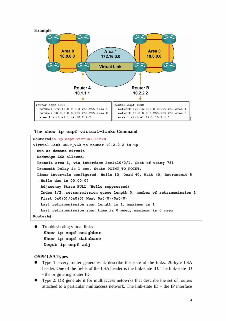
Large OSPF Network � Frequrnt SPF algorithm calculation � Large routing table � Large LSDB Solution: OSPF Hierarchical Routing � Reduced frequency of SPF calculation � Smaller routing tables � Reduced link-state update (LSU) overhead Types of OSPF Routers OSPF Virtual Links � Virtual links are used to connect a discontiguous area to area 0. � A logical connection is built between router A and router B. � Virtual links are recommended for backup or temporary connections. � Hello: 10s; LSA: 30m; DoNotAge (DNA): does not age out Configuring Virtual Links � R(config-router)#area area-id virtual-link router-id
[authentication [message-digest | null]] [hello-interval seconds] [retransmit-interval seconds] [transmit-delay seconds] [dead-interval seconds] [[authentication-key key] | [message-digest-key key-id md5 key]]
34
Example The show ip ospf virtual-links Command � Troubleshoting vittual links
- Show ip ospf neighbor - Show ip ospf database - Degub ip ospf adj
OSPF LSA Types � Type 1: every router generates it. describe the state of the links. 20-byte LSA
header. One of the fields of the LSA header is the link-state ID. The link-state ID - the originating router ID.
� Type 2: DR generate it for multiaccess netowrks that describe the set of routers attached to a particular multiaccess network. The link-state ID – the IP interface
RouterA# sh ip ospf virtual-links
Virtual Link OSPF_VL0 to router 10.2.2.2 is up
Run as demand circuit
DoNotAge LSA allowed.
Transit area 1, via interface Serial0/0/1, Cost o f using 781
Transmit Delay is 1 sec, State POINT_TO_POINT,
Timer intervals configured, Hello 10, Dead 40, Wa it 40, Retransmit 5
Hello due in 00:00:07
Adjacency State FULL (Hello suppressed)
Index 1/2, retransmission queue length 0, numbe r of retransmission 1
First 0x0(0)/0x0(0) Next 0x0(0)/0x0(0)
Last retransmission scan length is 1, maximum i s 1
Last retransmission scan time is 0 msec, maximu m is 0 msec
RouterA#

35
address of DR � Type 3&4: ABRs generate it. Type 3 describes routes to networks and aggregates
routes. Type 4 describes routes to ASBRs. Type 3 link-state ID – the destination network number. Type 4 link-state ID – the the router ID of the described ASBR. These LSAs are flooded throughout the backbone area to the other ABRs. These entries are not flooded into totally stubby areas or not-so-stubby areas (NSSAs).
� Type 5: ASBRs generate it. Describe routes to destinations external to the AS and flooded everywhere except stub areas, totally stubby areas and NSSAs. The link-state ID – the external network number
� Type 6: multicast OSPF applications. � Type 7: used in NSSAs. � Type 8: used in internetworking OSPF and Border Gateway Protocol (BGP). � Type 9,10&11: N/A
Type 1: Router LSA � One router LSA (type 1) for every router in an area
- Includes list of directly attached links - Each link identified by IP prefix assigned to link and link type

36
� Identified by the router ID of the originating router � Floods within its area only; does not cross ABR � Also desribe whether the router is an ABR or ASBR.
Type 2: Network LSA � One network (type 2) LSA for each transit broadcast or NBMA network in
an area - Includes list of attached routers on the transit link - Includes subnet mask of link � Advertised by the DR of the broadcast network � Floods within its area only; does not cross ABR Type 3: Summary LSA � Type 3 LSAs are used to flood network information to areas outside the
originating area (interarea)
37
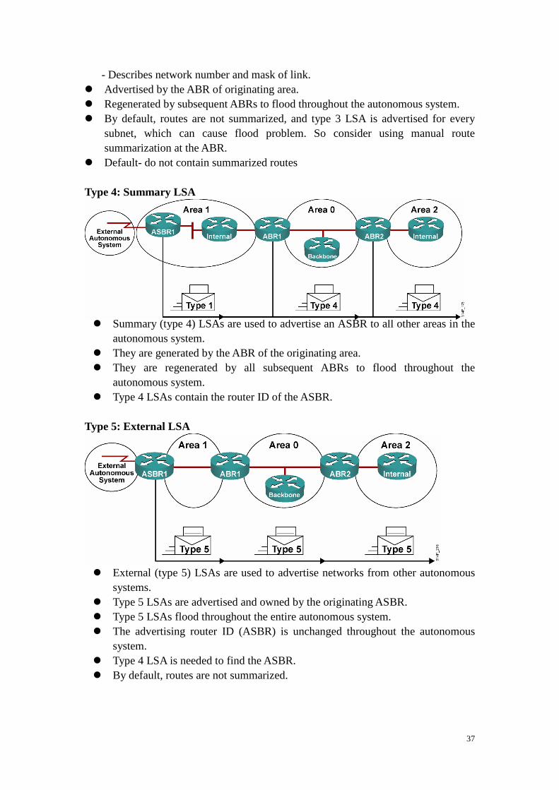
- Describes network number and mask of link. � Advertised by the ABR of originating area. � Regenerated by subsequent ABRs to flood throughout the autonomous system. � By default, routes are not summarized, and type 3 LSA is advertised for every
subnet, which can cause flood problem. So consider using manual route summarization at the ABR.
� Default- do not contain summarized routes Type 4: Summary LSA � Summary (type 4) LSAs are used to advertise an ASBR to all other areas in the
autonomous system. � They are generated by the ABR of the originating area. � They are regenerated by all subsequent ABRs to flood throughout the
autonomous system. � Type 4 LSAs contain the router ID of the ASBR.
Type 5: External LSA � External (type 5) LSAs are used to advertise networks from other autonomous
systems. � Type 5 LSAs are advertised and owned by the originating ASBR. � Type 5 LSAs flood throughout the entire autonomous system. � The advertising router ID (ASBR) is unchanged throughout the autonomous
system. � Type 4 LSA is needed to find the ASBR. � By default, routes are not summarized.

38
Interpreting the OSPF LSDB Interpreting the OSPF Routing Table: Types of Routes
Cost for E1 and E2 Routers – default: E2
RouterA#show ip ospf database
OSPF Router with ID (10.0.0.11) (Process ID 1)
Router Link States (Area 0)
Link ID ADV Router Age Se q# Checksum Link count
10.0.0.11 10.0.0.11 548 0x8 0000002 0x00401A 1
10.0.0.12 10.0.0.12 549 0x8 0000004 0x003A1B 1
100.100.100.100 100.100.100.100 548 0x800 002D7 0x00EEA9 2
Net Link States (Area 0)
Link ID ADV Router Age Se q# Checksum
172.31.1.3 100.100.100.100 549 0x80 000001 0x004EC9
Summary Net Link States (Area 0 )
Link ID ADV Router Age Se q# Checksum
10.1.0.0 10.0.0.11 654 0x8 0000001 0x00FB11
10.1.0.0 10.0.0.12 601 0x8 0000001 0x00F516
<output omitted>

39
The show ip rout Command Configuring OSPF LSDB Overload Protection � Excessive LSAs generated by other routers can drain local router resources. � This feature can limit the processing of non-self-generated LSAs for a defined
OSPF process. � R(config-router)# max-lsa maximum-number
[ threshold-percentage] [warning-only] [ignor-time minutes] [ignor-count count-number] [reset-time minutes]
RouterB >show ip route
Codes: C - connected, S - static, R - RIP, M - mobi le, B - BGP
D - EIGRP, EX - EIGRP external, O - OSPF, IA - OSPF inter area
N1 - OSPF NSSA external type 1, N2 - OSPF NS SA external type 2
E1 - OSPF external type 1, E2 - OSPF externa l type 2
i - IS-IS, su - IS-IS summary, L1 - IS-IS le vel-1, L2 - IS-IS level-2
ia - IS-IS inter area, * - candidate default , U - per-user static route
o - ODR, P - periodic downloaded static rout e
Gateway of last resort is not set
172.31.0.0/24 is subnetted, 2 subnets
O IA 172.31.2.0 [110/1563] via 10.1.1.1, 00:12:3 5, FastEthernet0/0
O IA 172.31.1.0 [110/782] via 10.1.1.1, 00:12:35 , FastEthernet0/0
10.0.0.0/8 is variably subnetted, 6 subnets, 2 masks
C 10.200.200.13/32 is directly connected, Loo pback0
C 10.1.3.0/24 is directly connected, Serial0/ 0/0
O 10.1.2.0/24 [110/782] via 10.1.3.4, 00:12:3 5, Serial0/0/0
C 10.1.1.0/24 is directly connected, FastEthe rnet0/0
O 10.1.0.0/24 [110/782] via 10.1.1.1, 00:12:3 7, FastEthernet0/0
O E2 10.254.0.0/24 [110/50] via 10.1.1.1, 00:12: 37, FastEthernet0/0

40
Changing the Cost Metric � Default = (100 Mbps)/(bandwidth in Mbps) � Use R(config-if)#bandwidth value to accurately define the bandwidth
of the interface (in kbps). � If the interfaces that are faster than 100Mbps, use auto-cost
reference-bandwidth ref-bw on all routers. ref-bw is a reference bandwidth in megabits per second (1-4,294,967).
� Voerride the default cost – R(config-if)#ip ospf cost interface-cost Cost value 1-65,535, the lower, the better and more strongly preferred the link

41
Lesson 6 OSPF Route Summarization
Benefits of Route Summarization � Minimizes number of routing table entries � Localizes impact of a topology change � Reducdes LSA type 3 and 5 flooding and saves CPU resources � Default – type 3&5 LSAs do not contain summarized routes Using Route Summarization � Classess routing protocol, support VLSM or discontiguous subnets � R(config-router)#area area-id range address mask
[advertise | not-advertise] [cost cost] - Consolidates interarea routes on an ABR
� R(config-router)#summary-address ip-address mask
[not-advertise] [tag tag] - Consolidates external routes, usually on an ASBR

42
Route Summarization configuration at ABR � Depending on network topology, you may not want to summarize are 0 networks
into other area – suboptimal path selection may occur. Route Summarization configuration at ASBR Benefit of a Default Route in OSPF � default-information originate
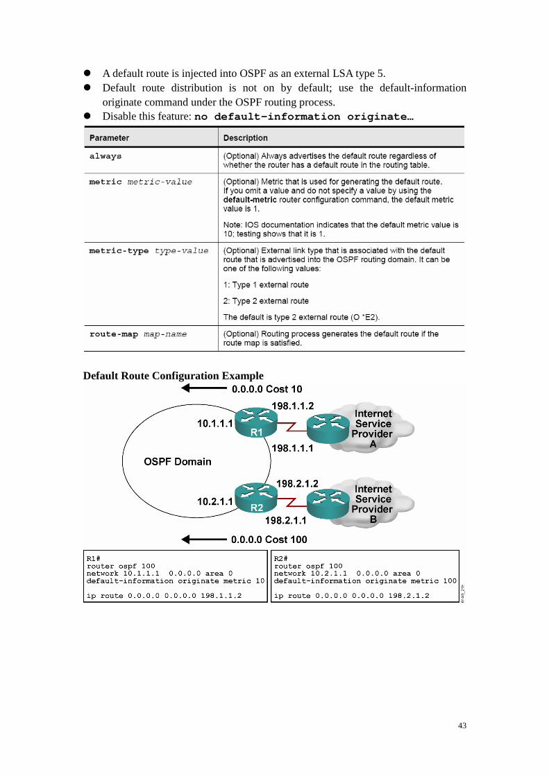
- Advertise 0.0.0.0 into the OSPF domain, provided that the advertising router already has a default route. - Advertise 0.0.0.0 regardless of whether the advertising router already has a default route. Default-information originate always
Configuring OSPF Default Routes � R(config-router)#default-information originate [always]
[metric metric-value] [metric-type type-value] [route-map map-name]
43
� A default route is injected into OSPF as an external LSA type 5. � Default route distribution is not on by default; use the default-information
originate command under the OSPF routing process. � Disable this feature: no default-information originate…
Default Route Configuration Example

44
Lesson 7 Configuring OSPF Special Area Types
Types of Areas � Standaer area: default – accept link updates, route summaries, external routes � Backbone area (transit area): area 0. � Stub area: does not accept information about routes external to the AS. Stub areas
cannot contain ASBRs (except the ABRs may also be ASBRs). � Totally stubby area: does not accept external AS routes or summary routes from
other areas internal to the AS. Totally stuby area cannot contain ASBRs (except the ABRs may also be ASBRs).
� NSSA: LSA type 7. NSSA allow ASBRs, which is against the rule in a stub area. Stub and Totally Stub Area Rules � An area can be stub or totally stub if:
- There is a single ABR, or if there is more than one ABR, suboptimal routing paths to other areas or external autonomous systems are acceptable. - All routers in the area must be configured as stub routers before they can become neighbors and exchange routing information - There is no ASBR inside the stub area. - The area is not the backbone area, area 0. - No virtual links go through the area.
Configuring Stub Areas � Configuring a stub area reduces the size of the LSDB inside an aera. External
network LSA(type 5) are not permitted to flood into a stub area � A stub area is typically created when a hub-and-spok topology is used, with the
spoke being the stub area. � R(config-router)#area area-id stub [no-summary]
- This command turns on stub area networking - All routers in a stub are must use the stub command.
� R(config-router)#area area-id default-cost cost - This command defines the cost of a default route sent into the stub area - The default cost is 1.

45
OSPF Stub Area Configuration � Each router in the stub ara must be configured with the area stub command Configuring Totally Stubby Areas � Cisco proprietary. Bolcks external (type 5) and summary (type 3&4). � Totally stubby area – only intra-arearoutes and the default route of 0.0.0.0. every
router picks the closest ABR as a gateway to everything outside the area. � If ABR is a Cisco router, using totally stubby area is better than using stub area. � R(config-router)#area area-id stub no-summary � Only ABRs use no-summary to keep summary LSAs form being propagated
into another area � All routers in a sbut or totally stubby area must bu configured as stub. An OSPF
adjacency will not form between stub and nonstub routers. Routing Table in a Standard Area
P1R3#sh ip route
<output omitted>
Gateway of last resort is not set
172.31.0.0/32 is subnetted, 4 subnets
O IA 172.31.22.4 [110/782] via 10.1.1.1, 00:02:4 4, FastEthernet0/0
O IA 172.31.11.1 [110/1] via 10.1.1.1, 00:02:44, FastEthernet0/0
O IA 172.31.11.2 [110/782] via 10.1.3.4, 00:02:5 2, Serial0/0/0
[110/782] via 10.1.1.1, 00:02:5 2, FastEthernet0/0
O IA 172.31.11.4 [110/782] via 10.1.1.1, 00:02:4 4, FastEthernet0/0
10.0.0.0/8 is variably subnetted, 7 subnets, 2 masks
O 10.11.0.0/24 [110/782] via 10.1.1.1, 00:03: 22, FastEthernet0/0
C 10.200.200.13/32 is directly connected, Loo pback0
C 10.1.3.0/24 is directly connected, Serial0/ 0/0
O 10.1.2.0/24 [110/782] via 10.1.3.4, 00:03:2 3, Serial0/0/0
C 10.1.1.0/24 is directly connected, FastEthe rnet0/0
O 10.1.0.0/24 [110/782] via 10.1.1.1, 00:03:2 3, FastEthernet0/0
O E2 10.254.0.0/24 [110/50] via 10.1.1.1, 00:02: 39, FastEthernet0/0
P1R3#

46
Routing Table in a Stub area Routing Table in a Stub area with summarization
P1R3#sh ip route
<output omitted>
Gateway of last resort is 10.1.1.1 to network 0.0.0 .0
172.31.0.0/32 is subnetted, 4 subnets
O IA 172.31.22.4 [110/782] via 10.1.1.1, 00:01:4 9, FastEthernet0/0
O IA 172.31.11.1 [110/1] via 10.1.1.1, 00:01:49, FastEthernet0/0
O IA 172.31.11.2 [110/782] via 10.1.3.4, 00:01:4 9, Serial0/0/0
[110/782] via 10.1.1.1, 00:01:4 9, FastEthernet0/0
O IA 172.31.11.4 [110/782] via 10.1.1.1, 00:01:4 9, FastEthernet0/0
10.0.0.0/8 is variably subnetted, 6 subnets, 2 masks
O 10.11.0.0/24 [110/782] via 10.1.1.1, 00:01: 50, FastEthernet0/0
C 10.200.200.13/32 is directly connected, Loo pback0
C 10.1.3.0/24 is directly connected, Serial0/ 0/0
O 10.1.2.0/24 [110/782] via 10.1.3.4, 00:01:5 0, Serial0/0/0
C 10.1.1.0/24 is directly connected, FastEthe rnet0/0
O 10.1.0.0/24 [110/782] via 10.1.1.1, 00:01:5 0, FastEthernet0/0
O*IA 0.0.0.0/0 [110/2] via 10.1.1.1, 00:01:51, Fast Ethernet0/0
P1R3#
P1R3#sh ip route
<output omitted>
Gateway of last resort is 10.1.1.1 to network 0.0.0 .0
172.31.0.0/16 is variably subnetted, 2 subnets , 2 masks
O IA 172.31.22.4/32 [110/782] via 10.1.1.1, 00:1 3:08, FastEthernet0/0
O IA 172.31.11.0/24 [110/1] via 10.1.1.1, 00:02: 39, FastEthernet0/0
10.0.0.0/8 is variably subnetted, 6 subnets, 2 masks
O 10.11.0.0/24 [110/782] via 10.1.1.1, 00:13: 08, FastEthernet0/0
C 10.200.200.13/32 is directly connected, Loo pback0
C 10.1.3.0/24 is directly connected, Serial0/ 0/0
O 10.1.2.0/24 [110/782] via 10.1.3.4, 00:13:0 9, Serial0/0/0
C 10.1.1.0/24 is directly connected, FastEthe rnet0/0
O 10.1.0.0/24 [110/782] via 10.1.1.1, 00:13:0 9, FastEthernet0/0
O*IA 0.0.0.0/0 [110/2] via 10.1.1.1, 00:13:09, Fast Ethernet0/0
P1R3#

47
Routing Table in a Totally Stubby area Configurint NSSAs � Nonproprietary extension of existing stub area feature that allows the jinection of
external routes in a limited fashion into the stub area. � Type 7 -> type 5 � Type 7 in routing table – O N2 or O N1 (default – N2) � R(config-router)#area area-id nssa [no-redistribution]
[default-information-originate [metric metric-value] [metric-type type-value]] [no-summary] - The no-summary keyword creates an NSSA totally stubby area; this is a Cisco proprietary feature. � All routers in the NSSA must have this command configured; router will not form
an adjacency unless both aer configured as NSSA.
P1R3#sh ip route
<output omitted>
Gateway of last resort is 10.1.1.1 to network 0.0.0 .0
10.0.0.0/8 is variably subnetted, 6 subnets, 2 masks
O 10.11.0.0/24 [110/782] via 10.1.1.1, 00:16: 53, FastEthernet0/0
C 10.200.200.13/32 is directly connected, Loo pback0
C 10.1.3.0/24 is directly connected, Serial0/ 0/0
O 10.1.2.0/24 [110/782] via 10.1.3.4, 00:16:5 3, Serial0/0/0
C 10.1.1.0/24 is directly connected, FastEthe rnet0/0
O 10.1.0.0/24 [110/782] via 10.1.1.1, 00:16:5 3, FastEthernet0/0
O*IA 0.0.0.0/0 [110/2] via 10.1.1.1, 00:00:48, Fast Ethernet0/0
P1R3#

48
Example: NSSA Configuration Example: NSSA Totally Stubby Configuration – Cisco proprietary feature Verifying All Stub Area Types � R#show ip ospf � R#show ip ospf database � R#show ip ospf database nssa-external � R#show ip route

49
Lesson 8 Configuring OSPF Authentication
OSPF Authentication Types � OSPF supports 2 types of authentication:
- Simple password (or plain text) authentication - MD5 authentication � Router generates and checks every OSPF packet. Router authenticates the source
of each routing update packet that it receives. � Configure a “key” (password); each participating neighbor must have same key
configured. � OSPF MD5 authentication includes a nondecreasing sequence number in each
OSPF packet to protect against reply attacks. Configuring OSPF Simple Password Authentication � R(config-if)#ip ospf authentication-key password
- If the service password-encrytpion command is not used when configuring OSPF authentication, the key will be stored as plain text in the router configuration. If you configure the service password-encrytpion command, the key will be stored and displayed in an encrypted form; when it is displayed, there will be an encryption-type of 7 specified before encrypted key. � R(config-if)#ip ospf authentication-key [message-digest
| null]
- For simple password authentication, use the ip ospf authentication-key
command with no parameters. � R(config-if)#area area-id authentication-key
[message-digest]

50
Example: Simple Password Authentication configuration

51
Verifying Simple Password Authentication Configuring OSPF MD5 Authentication � R(config-if)#ip ospf message-digest-key key-id md5 key
- The same key-id on the neighbor router must have the sme key value. - The key ID allows for uninterrupted transitions between keys. If an interface is configured with a new key, the router will send multiple copies of the same packet, each authenticatied by different keys. The router will stop sending duplicated packets when it detects that all of its neighbors have adopted the new key. - It is recommended that only keep one key per interface. - If the service password-encrytpion command is not used when configuring OSPF authentication, the key will be stored as plain text in the router configuration. If you configure the service password-encrytpion command, the key will be stored and displayed in an encrypted form; when it is displayed, there will be an encryption-type of 7 specified before encrypted key. � R(config-if)#ip ospf authentication [message-digest |
null]
R1#sh ip ospf neighbor
Neighbor ID Pri State Dead Time A ddress Interface
10.2.2.2 0 FULL/ - 00:00:32 1 92.168.1.102 Serial0/0/1
R1#show ip route
<output omitted>
Gateway of last resort is not set
10.0.0.0/8 is variably subnetted, 2 subnets, 2 masks
O 10.2.2.2/32 [110/782] via 192.168.1.102, 00 :01:17, Serial0/0/1
C 10.1.1.0/24 is directly connected, Loopback 0
192.168.1.0/27 is subnetted, 1 subnets
C 192.168.1.96 is directly connected, Serial0 /0/1
R1#ping 10.2.2.2
Type escape sequence to abort.
Sending 5, 100-byte ICMP Echos to 10.2.2.2, timeout is 2 seconds:
!!!!!
Success rate is 100 percent (5/5), round-trip min/a vg/max = 28/29/32 ms

52
- Use ip ospf authentication message-digest for MD5 authentication. � R(config-area)#area area-id authentication
[message-digest] Example: MD5 Authentication configuration
53
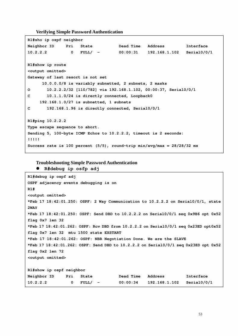
Verifying Simple Password Authentication Troubleshooting Simple Password Authentication � R#debug ip osfp adj
R1#sho ip ospf neighbor
Neighbor ID Pri State Dead Time A ddress Interface
10.2.2.2 0 FULL/ - 00:00:31 1 92.168.1.102 Serial0/0/1
R1#show ip route
<output omitted>
Gateway of last resort is not set
10.0.0.0/8 is variably subnetted, 2 subnets, 2 masks
O 10.2.2.2/32 [110/782] via 192.168.1.102, 00 :00:37, Serial0/0/1
C 10.1.1.0/24 is directly connected, Loopback 0
192.168.1.0/27 is subnetted, 1 subnets
C 192.168.1.96 is directly connected, Serial0 /0/1
R1#ping 10.2.2.2
Type escape sequence to abort.
Sending 5, 100-byte ICMP Echos to 10.2.2.2, timeout is 2 seconds:
!!!!!
Success rate is 100 percent (5/5), round-trip min/a vg/max = 28/28/32 ms
R1#debug ip ospf adj
OSPF adjacency events debugging is on
R1#
<output omitted>
*Feb 17 18:42:01.250: OSPF: 2 Way Communication to 10.2.2.2 on Serial0/0/1, state
2WAY
*Feb 17 18:42:01.250: OSPF: Send DBD to 10.2.2.2 on Serial0/0/1 seq 0x9B6 opt 0x52
flag 0x7 len 32
*Feb 17 18:42:01.262: OSPF: Rcv DBD from 10.2.2.2 o n Serial0/0/1 seq 0x23ED opt0x52
flag 0x7 len 32 mtu 1500 state EXSTART
*Feb 17 18:42:01.262: OSPF: NBR Negotiation Done. W e are the SLAVE
*F eb 17 18:42:01.262: OSPF: Send DBD to 10.2.2.2 on S erial0/0/1 seq 0x23ED opt 0x52
flag 0x2 len 72
<output omitted>
R1#show ip ospf neighbor
Neighbor ID Pri State Dead Time A ddress Interface
10.2.2.2 0 FULL/ - 00:00:34 1 92.168.1.102 Serial0/0/1

54
Troubleshooting Simple Password Authentication Problems � Simple authentication on R1, no authentication on R2 - type 0: null; type 1: simple password; type 2: MD5 � Simple authentication on R1 and R2, but different passwords Troubleshooting MD5 Authentication � R#debug ip osfp adj
R1#
*Feb 17 18:51:31.242: OSPF: Rcv pkt from 192.168.1. 102, Serial0/0/1 : Mismatch
Authentication type. Input packet specified type 0, we use type 1
R2#
*Feb 17 18:50:43.046: OSPF: Rcv pkt from 192.168.1. 101, Serial0/0/1 : Mismatch
Authentication type. Input packet specified type 1, we use type 0
R1#
*Feb 17 18:54:01.238: OSPF: Rcv pkt from 192.168.1. 102, Serial0/0/1 : Mismatch
Authentication Key - Clear Text
R2#
*Feb 17 18:53:13.050: OSPF: Rcv pkt from 192.168.1. 101, Serial0/0/1 : Mismatch
Authentication Key - Clear Text
R1#debug ip ospf adj
OSPF adjacency events debugging is on
<output omitted>
*Feb 17 17:14:06.530: OSPF: Send with youngest Key 1
*Feb 17 17:14:06.546: OSPF: 2 Way Communication to 10.2.2.2 on Serial0/0/1,
state 2WAY
*Feb 17 17:14:06.546: OSPF: Send DBD to 10.2.2.2 on Serial0/0/1 seq 0xB37
opt 0x52 flag 0x7 len 32
*Feb 17 17:14:06.546: OSPF: Send with youngest Key 1
*Feb 17 17:14:06.562: OSPF: Rcv DBD from 10.2.2.2 o n Serial0/0/1 seq 0x32F
opt 0x52 flag 0x7 len 32 mtu 1500 state EXSTART
*Feb 17 17:14:06.562: OSPF: NBR Negotiation Done. W e are the SLAVE
*Feb 17 17:14:06.562: OSPF: Send DBD to 10.2.2.2 on Serial0/0/ 1 seq 0x32F
opt 0x52 flag 0x2 len 72
*Feb 17 17:14:06.562: OSPF: Send with youngest Key 1
<output omitted>
R1#show ip ospf neighbor
Neighbor ID Pri State Dead Time A ddress Interface
10.2.2.2 0 FULL/ - 00:00:35 1 92.168.1.102 Serial0/0/1

55
Troubleshooting MD5 Authentication Problems � MD5 authentication on both R1 and R2, but R1 has key 1 and R2 has key 2, both
with the same passwords:
R1#
*Feb 17 17:56:16.530: OSPF: Send with youngest Key 1
*Feb 17 17:56:26.502: OSPF: Rcv pkt from 192.168.1.102, Serial0/0/1 : Mismatch
Authentication Key - No message digest key 2 on int erface
*Feb 17 17:56:26.530: OSPF: Send with youngest Key 1
R2#
*Feb 17 17:55:28.226: OSPF: Send with youngest Key 2
*Feb 17 17:55:28.286: OSPF: Rcv pkt from 192 .168.1.101, Serial0/0/1 : Mismatch
Authentication Key - No message digest key 1 on int erface
*Feb 17 17:55:38.226: OSPF: Send with youngest Key 2

56
Module 4 The IS-IS Protocol
Lesson 1 Introducing IS-IS and Integrated IS-IS Routing
Uses for IS-IS Routing – Large ISPs IS-IS Routing � IS = router � IS-IS it a part of the Open Systems Interconnection (OSI) suit of protocols � OSI suite uses Connectionless Network Service (CLNS) to provide
connectionless delivery of data, and the actual Layer 3 protocol is Connetionless Network Protocol (CLNP).
� CLNP is the solution for “unreliable” (connctionless) delivery fo data, similar to IP.
� IS-IS uses CLNS address to identify the routers and to build the LSDB. � IS-IS – CLNS; integrated IS-IS – IP & CLNS IS-IS Feature � Link-state routing protocol � Supports VLSM � Uses Dijkstra’s SPF algorithm; has fast convergence � Distributes routing information for routing CLNP data for the ISO CLNS
environment � Uses hellos to establish adjacencies and LSPs to exchange link-state information � Efficient use of bandwidth, memory, and processor � Supports two routing levels within an AS:
- Level 1: Builds common topology of system IDs in local area and routes within area using lowest cost path. All devices in a Level 1 routing area have the same area address. - Level 2: Exchanges prefix information (area addresses) between areas. All ISs in a Level 2 routing area use the destination area adderss to route traffic using the lowest-cost path
IS-IS Link-State Operation
57
� Level 1 routers use LSPs to build topology for local area. (intra-area) � Level 2 routers use LSPs to build topology between different areas. (interarea) � Level 1-2 routers act as border routers between Level 1 and Level 2 routing
domains. (=ABRs in OSPF) � The path of connected Level 2 and Level 1-2 routers is called the backbone. All
areas and the backbone must be contiguous. � All boundaries fall on the links. Each IS-IS router belongs to exactly one area Integrated (or Dual ) IS-IS Routing � Integrated IS-IS is IS-IS for multiple protocols - IP, CLNS, or both � Uses its own PDUs to transport IP routing information; updates not sent in IP
packets. IS-IS information is not carried within a network-layer protocol but is instead carried directly within data link layer frames.
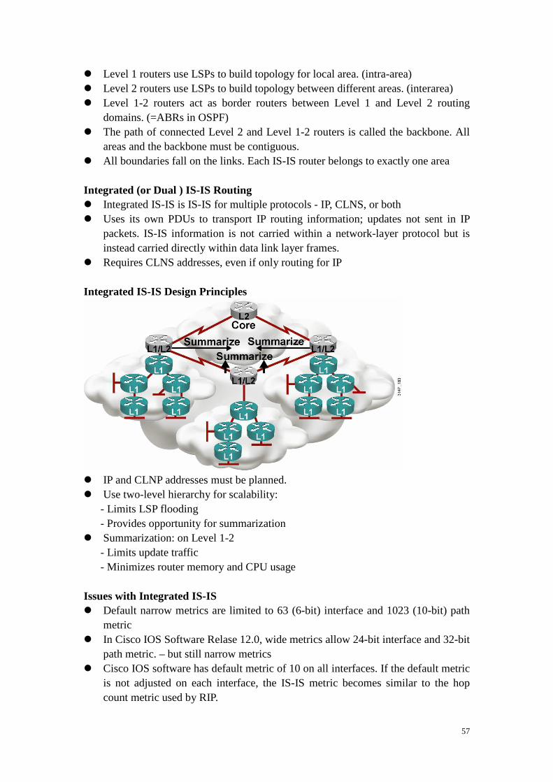
� Requires CLNS addresses, even if only routing for IP Integrated IS-IS Design Principles � IP and CLNP addresses must be planned. � Use two-level hierarchy for scalability:
- Limits LSP flooding - Provides opportunity for summarization � Summarization: on Level 1-2
- Limits update traffic - Minimizes router memory and CPU usage
Issues with Integrated IS-IS � Default narrow metrics are limited to 63 (6-bit) interface and 1023 (10-bit) path
metric � In Cisco IOS Software Relase 12.0, wide metrics allow 24-bit interface and 32-bit
path metric. – but still narrow metrics � Cisco IOS software has default metric of 10 on all interfaces. If the default metric
is not adjusted on each interface, the IS-IS metric becomes similar to the hop count metric used by RIP.

58
ES-IS Protocol � ES-IS forms adjacencies between ESs and routers (ISs)
- IP end-systems do not use ES-IS. IP has its own – ICMP, ARP, DHCP � ESs transmit ESHs to announce their presence to ISs. � ISs transmit ISHs to announce their presence to ESs. � ISs transmit IIHs to other ISs. � If ES send a packet to another ES, it sends the packet to one of the ISs (routers)
on its directly attached network. Four OSI Routing Levels � Level 0: ES-IS � Level 1 and Level 2 : IS-IS
- Level 1 routing is also called intra-area routing. - Level 2 routing is also called interarea routing. � Level 3 OSI routing is not implented on Cisco routers but is specified as being
accomplished through the Interdomain Routing Protocol (IDRP)

59
IS-IS and OSPF Similarity � Integrated IS-IS and OSPF are both open standard link-state protocols with the
following similar features: - Link-state advertisements (LSAs), aging timers, and LSDB synchronization to maintain the health of LSDB - SPF algorithms - Update, decision, and flooding processes - VLSM support � Scalability of link-state protocols has been proven (used in ISP backbones). � They both converge quickly after changes. Integrated IS-IS vs. OSPF: Area Design � OSPF is based on a central backbone with all other areas attached to it.
- In OSPF the border is inside routers (ABRs). - Each link belongs to one area.
� In IS-IS the area borders lie on links
- Each IS-IS router belongs to exactly one area. - IS-IS is more flexible when extending the backbone. The backbone can be extended by simply adding more Level 2 and Level 1-2 routers.
Advantages of Integrated IS-IS � OSPF produces many small LSAs. IS-IS updates are grouped by the router and
sent as one LSP. With the network complexity increases, more LSAs than LSP. So make IS-IS more scalable than OSPF.
� OSPF runs on top of IP, IS-IS run through CLNS. � IS-IS is less CPU-intensive than OSPF � IS-IS converge faster than OSPF � IS-IS is easy to extend throught he Type, Length, Value (TLV) mechanism. TLV
stings, called tuples, encode all IS-IS updates. IS-IS can easily grow to cover Ipv6 or any other protocol, because extending IS-IS consists simply of creating new

60
type codes. Advantages of OSPF � OSPF has more features, including:
- Has three area types: normal, stub, and NSSA - Defaults to scaled metric (IS-IS always 10) � OSPF is supported by many vendors. � Information, examples, and experienced engineers are easier to find. Summary of Difference between OSPF and Integrated IS-IS

61
Lesson 2 Performing IS-IS Routing Operations
� CLNS address apply to entire nodes and not to interfaces. � CLNS address that are used by routers are called network service access points
(NSAPs). � One part of an NSAP address is the NSAP selector (NSEL) byte. If NSEL = 0,
then the NSAP is called the network entity thtle (NET). OSI (Open Systems Interconnection) Address � OSI network layer addressing is implemented with NSAP addresses. � IS-IS link-state packets (LSPs) use NSAP address to identify the router and build
the topology table and the underlying IS-IS routing tree � NSAP address contain: OSI address of the device; Link to the higher-layer
process � An NSAP address identifies a system in the OSI network; an address represents
an entire node, not an interface. � Various NSAP formats are used in various systems, because different protocols
may use different representations of NSAP. � NSAP address = IP address + upper-layer protocol in an IP header � NSAP addresses are a maximum of 20 bytes:
- Higher-order bits identify the interarea structure. - Lower-order bits identify unique systems within area.
Integrated IS-IS NSAP Addres Structure � The Cisco implementation of Integrated IS-IS distinguishes only the following
three fields in the NSAP address: - Area address: Variable-length field (1 to 13 octets) composed of the higher-order NSAP octets, excluding system ID and NSEL. - System ID: ES or IS identifier in an area; fixed length of six octets in Cisco IOS software. - NSEL: One octet NSAP selector, service identifier. � Total length of NSAP is from 8 (minimum) to 20 octets (maximum). � AFI and IDI make up IDP (initial domain part) of the NSAP address
- AFI – authorith and format identifier. 49 - private - IDI – initial domain identifier.
Typical NSAP Address Structure � Area address (must be at least 1 byte)
- AFI set to 49 - Locally administered; thus, you can assign your own addresses. - Area ID - The octets of the area address after the AFI.

62
� System ID - Cisco routers require a 6-byte system ID. � NSEL - Always set to 0 for a router. � The NSAP is called the NET if NSEL = 0. Routers use the NET to identify
themselves in the IS-IS protocol data units (PDUs). � 49.0001.0000.0c12.3456.00
- AFI – 49 - Area ID – 0001 - System ID - 0000.0c12.3456, the MAC address of a LAN interface - NSEL - 0
Identifying Systems in IS-IS: Area Address � All routers within an area must use the same area address. � An ES may be adjacent to a router only if they share a common area address. � Area address is used in Level 2 routing. Identifying Systems in IS-IS: System ID � System ID in the address used to identify the IS; it is not just an interface. Cisco
supports only a 6-byte system ID. � System ID is used in Level 1 routing and has to be unique within an area. � System ID has to be unique within Level 2 routers that form the routing domain. � General recommendation: use domain-wide unique system ID.
- This may be MAC (for example, 0000.0c12.3456) or IP address. (for example, 1921.6800.0001) taken from an interface.
OSI Addressing: NET Address � NSAP address includes NSEL field (process or port number) � NET: NSAP with a NSEL field of 0
- Refers to the device itself (equivalent to the Layer 3 OSI address of the device) - Used in routers because they implement the network layer only (base for SPF calculation)
Sbunetwork Point of Attachment (SNPA) and Circuit � Three additional IS-IS terms: SNPA, circuit, link � SNPA is the point that provides subnetwork services. SNPA is equivalent to Layer
2 address - MAC address on a LAN interfaces - Virtual circuit ID from X.23 or ATM; data-link connection identifier (DLCI) from Frame Relay connections - For High-Level Data Link Control (HDLC) interfaces, simply “HDLC” � Circuit is the IS-IS term for an interface. Circuit ID is used to distinguish a
particular interface (one Octet) - On Point-to-point interfaces, SNPA is the sole identifier for the circuit. For example HDLC point-to-point link ,circuit ID is 0x00. - On LAN interfaces, circuit ID is tagged to the end of the system ID (6 octet) of

63
the Designated IS (DIS) to form 7-octet LAN ID. For example, 1921.6800.0001.01. - Cisco router use host name instead of system ID. For example “R1.01”. � Link is the path between two neighbor ISs and is defined as being up when
communication is possible between the two neighbor SNPAs. IS-IS Routing Levels � Level 1 (like OSPF internal nonbackbone routers):
- Intra-area routing enables ESs to communicate. - Level 1 area is a collection of Level 1 and Level 1-2 routers. - Level 1 IS keeps copy of the Level 1 area LSDB. � Level 1-2 (like OSPF ABR):
- Intra-area and interarea routing. - Level 1-2 IS keeps separate Level 1 and Level 2 LSDBs and advertises default route to Level 1 routers. � Level 2 (like OSPF backbone routers):
- Interarea routing. - Level 2 (backbone) area is a contiguous set of Level 1-2 and Level 2 routers. - Level 2 IS keeps a copy of the Level 2 area LSDB. � The path of connected Level 2 and Level 1-2 routers is called the backbone. All
areas and the backbone must be contiguous. � Area boundaries fall on the links. Each IS-IS router belongs to exactly one area. Intra-Area and Interarea Addressing and Routing � Area address is used to route between areas; system ID is not considered. � System ID is used to route within an area; area address is not considered. OSI IS-IS Routing Logic � Level 1 router: For a destination address, compare the area address to this area.
- If not equal, pass to nearest Level 1-2 router. - If equal, use Level 1 database to route by system ID. � Level 1-2 router: For a destination address, compare the area address to this area.
- If not equal, use Level 2 database to route by area address. - If equal, use Level 1 database to route by system ID. � Each router makes its own best-path decisions at every hop along the way, so the
return traffic can take a different path than the outgoing traffic.

64
Route Leaking � Available since Cisco IOS Sofware Release 12.0 � Helps reduce suboptimal routing by allowing Level 2 information to be leaked
into Level 1 � Uses up/down bit in Type, Length, and Value (TLV) field
- Up/down bit = 0: the route was originated within that Level 1 area - Up/down bit = 1: the route has been redistributed into the area from Level 2. - Up/down bit is used to prevent routing loops: a Level 1-2 router does not readvertise into Level 2 any Level 1 routes that have the up/down bit set.
IS-IS PDUs � PDU between peers:
- Network PDU = datagram, packet - Data-link PDU = frame � IS-IS and ES-IS PDUs are encapsulated directly in a data-link PDU (frame); there
is no CLNP header and no IP header. ( in other words, IS-IS and ES-IS do not put routing information in IP or CLNP packet, rather they put routing informationdirectly in a data link layer frame.)
� True CLNP (data) packets contain a full CLNP header between the data-link
Must support Level 2 routing to ensure that the backbone is contiguous.

65
header and any higher-layer CLNS information IS-IS PDU � IS-IS PDUs are encapsulated directly into a data-link frame. There is no CLNP or
IP header in a PDU. � IS-IS PDUs are as follows:
- Hello (ESH, ISH, IIH): used to establish and maintain adjacencies - LSP: used to distribute link-state information - PSNP (partial sequence number PDU): used to acknowledge and request missing pieces of link-state information - CSNP (complete sequence number PDU): used to describe the complete list of LSPs in the LSDB of a router
Link-State Packet Represents Router � LSP contains an LSP header and TLV fields � LSP header:
- PDU type and length - LSP ID - LSP sequence number: identify duplicate LSPs and to ensure that the latest LSP information is stored in the topology table - Remaining lifetime: age out LSPs � TLV :
- IS neighbors: build the map of the network - ES neighbors - Authentication information: secure routing updates - Attached IP subnets (optional for Integrated IS-IS)
LSP Header � LSPs are sequenced to prevent duplication of LSPs.
- Assists with synchronization. - Sequence numbers begin at 1. - Sequence numbers are increased to indicate the newest LSP.
- Ensure the latest LSPs in their route calculations - Aviod entering duplicate LSPs in the topology tables - If a router reloads, the sequence number is set to 1. the router then receives its previous LSPs from its neighbors. Thes LSPs have the last valid sequence number before the router reloaded. The router records this number and reissues its own LSPs with the next-highest sequence number
� LSPs in LSDB have a remaining lifetime. - Allows synchronization. - Decreasing timer. - ensure the removal of outdated and invalided LSPs from the topology table after a suitable time. - count to zero operation from 1200 seconds (default)

66
LSP TLV Examples
IS-IS Network Representation � Generally, physical links can be placed in the following two groups:
- Broadcast: Multipoint WAN links or LAN links such as Ethernet, Token Ring, or FDDI - Point-to-point: Permanent established (Leased line, permanent virtual circuit (PVC)) or dynamically established (ISDN, switched virtual circuit (SVC)) links � Only two link-state representations are available in IS-IS:
- Broadcast for LANs and multipoint WANs - Point-to-point for all other topologies � IS-IS has no concept of NBMA networks. Recommend: use point-to-point links,
such as point-to-point subinterface, over NBMA networks such as ATM, Frame Relay, or X.25.
Implementing IS-IS in NBMA (such as Frame Relay, ATM) � Broadcast mode assuems fully meshed connectivity. � In broadcast mode, you must enable CLNS mapping and include the
broadcast keyword: frame-relay map clns dlci-number broadcast , in addition to creating the IP maps with the broadcast keyword.
� Point-to-point mode is highly recommended (using subinterfaces). Implementing IS-IS in Broadcast Netowrks � Used for LAN and multipoint WAN interfaces.
- Recommend for use only on LAN interface. � Adjacency is recognized through hellos; separate adjacencies for Level 1 and
Level 2. � Designated IS (DIS) creates a pseudonode and represents LAN. � DIS is elected based on these criteria: (Only routers with adjacencies are eligible)
- Highest interface priority. (the priority value is configurable) - Highest SNPA (MAC) breaks ties. � Default priority for Level 1 and Level 2 is 64. Can be confirgured from 0 to 127.

67
command: isis priority number-value [level-1 | level-2] . The Level 1 DIS and the Level 2 DIS on a LAN may or may not be the same router because an interface can have different Level 1 and Level 2 priorities.
� A selected router is not guaranteed to remain the DIS. Any adjacent with a higher priority automaticaly takes over the DIS role. This behaviro is called preemptive. There is no backup DIS.
LSP Representing Routers: LAN Representation � n connected ISs would require n (n-1)/2 adjacency advertisements Level 1 and Level 2 LSPs and IIHs � The two-level nature of IS-IS requires separate types of LSPs: Level 1 and Level
2 LSPs. � DIS is representative of LAN:
- DIS sends pseudo-Level 1 and pseudo-Level 2 LSPs for LAN. - Separate DIS for Level 1 and Level 2. � LSPs are sent as unicast on point-to-point networks. � LSPs are sent as multicast on broadcast networks (LANs). � LAN uses separate Level 1 and Level 2 IIHs; sent as multicast. � Point-to-point uses a common IIH format; sent as unicast.

68
Comparing Broadcast and Point-to-Point Topology
LSP Flooding � Single procedure for flooding, aging, and updating of LSPs. � Level 1 LSPs are flooded within an area. � Level 2 LSPs are flooded throughout the Level 2 backbone. � Large PDUs are divided into fragments that are independently flooded.
- Each PDU is assigned an LSP fragment number, starting at 0 and incrementing by 1. � Separate LSDBs are maintained for Level 1 and Level 2 LSPs. LSDB Synchronization � SNP (Sequence number PDUs) packets are used to ensure synchronization and
reliability. Two type of SNPs: CSNP, PSNP. - Contents are LSP descriptions � PSNP is used for the following:
- For acknowledgment of LSPs on point-to-point links - To request missing pieces of LSDB � CSNP is used for the following:
- Periodically by DIS on LAN to ensure LSDB accuracy - On point-to-point link when the link comes up
LSDB Synchronization: LAN � On a LAN, the DIS periodically (every 10 seconds) sends CSNPs that list the
LSPs that it holds in its LSDB. This update is a multicast to all Level 1 or Level 2 IS-IS routers on the LAN.

69
LSDB Synchronization: Point-to-Point � CSNPs are not periodically sent on point-to-point links, a CSNP is sent only once,
when the point-to-point link first becomes active. After that, LSPs are sent to describe topology changes, and they are acknowledged with a PSNP.
LAN Adjacencies � Adjacencies are established based on the area address announced in the incoming
IIHs and the type of the router.
WAN Adjacencies
� Level 1 router in the same area exchange IIH PDUs that specify Level 1 and
establish a Level 1 adjacency. � Level 2 routers exchange IIH PDUs that specify Level 2 and establish a Level 2

70
adjacency. � Two Level 1-2 routers in the same area establish both Level 1 and Level 2
adjacencies and maintain these with a common IIH PDU that specifies the Level 1 and Level 2 information.
� Two level 1 router that are physically connected, but that are not in the sam area, can exchange IIHs, but they do not establish adjacency because the area addresses do not match.

71
Lesson 3 Configuring Basic Integrated IS-IS
Integrated IS-IS: Requires NET Address � A NET address identifies a device (IS or ES) and not an interface. This is a
critical difference between a NET address and an IP address. � Common CLNS parameters (NET) and area planning are still required even in an
IP environment. � Even when Integrated IS-IS is used for IP routing only, routers still establish
CLNS adjacencies and use CLNS packets. OSI Area Routing: Building an OSI Forwarding Database (Routing Table) � When databases are synchronized, Dijkstra’s algorithm (SPF) is run on the LSDB
to calculate the SPF tree. � The shortest path to the destination is the lowest total sum of metrics. � Separate route calculations are made for Level 1 and Level 2 routes in Level 1-2
routers. � Best paths are placed in the OSI forwarding database (CLNS routing table). Building an IP Routing Table � Partial route calculation (PRC) is run to calculate IP reachability.
- Because IP and ES are represented as leaf objects, they do not participate in SPF. � Best paths are placed in the IP routing table following IP preferential rules.
- They appear as Level 1 or Level 2 IP routes. Integrated IS-IS Configuration Steps � Define areas, prepare addressing plan (NETs) for routers, and determine
interfaces. � Enable IS-IS on the router. router isis [ area-tag] � Configure the NET. net network-entity-title � Enable Integrated IS-IS on the appropriate interfaces. Do not forget interfaces to
stub IP networks, such as loopback interfaces (although there are no CLNS neighbors there). ip router isis [ area-tag]
Step 1: Define Area and Addressing � Area determined by NET prefix

72
- Assign to support two-level hierarchy. � Addressing
- IP: Plan to support summarization. - CLNS: Prefix denotes area. System ID must be unique.
Step 2: Enable IS-IS on the Router � router(config)#router isis [ area-tag]
- enable the IS-IS routing protocol. area-tag – name for a process - CLNS routing is disabled by default. When routing of CLNS packets is also needed, use the clns routing command. Additionally, you must enable CLNS routing at each interface. � By default, Cisco IOS software makes the router a Level 1-2 router. Step 3: Configure the NET � router(config-router)#net network-entity-title
- Configure a IS-IS NET address for the routing process Step 4: Enable Integrated IS-IS � router(config-if)#ip router isis [ area-tag]
- Includes an interface in an IS-IS routing process � Do not forget interfaces to stub IP networks,such as loopback interfaces (even
though there aer no CLNS neighbors on those interfaces). � Use the clns router isis [ area-tag] , to enable the IS-IS routing process
on an interface to support CLNS routing. Simple Integrated IS-IS Example � CLNS routing is not enabled. � No level has been configured under the IS-IS routing process, the router acts as a
Level 1-2 router by default.
interface FastEthernet0/0
ip address 10.1.1.2 255.255.255.0
ip router isis
!
interface Serial 0/0/1
ip address 10.2.2.2 255.255.255.0
ip router isis
!
<output omitted>
router isis
net 49.0001.0000.0000.0002.00

73
Change IS-IS Router Level � router(config-router)#is-type {level-1 | levle-1-2 |
level-2-only} - default: Level 1-2
Change IS-IS Interface Level � router(config-if)#isis circuit-type {level-1 | levle-1-2
| level-2-only} - default: Level 1-2
Change IS-IS Metric � router(config-if)#isis metric metric [ delay-netric
[ expense-metric [ error-metric]]] {level-1 | level-2 } - Configures the metric for an interface; the default is 10 - Metric value is from 1 to 63. � router(config-router)#metric default-value {level-1 |
level-2 } - Alternately, configures the metric globally for all interfaces. - If the keyworkd level-1 or level-2 is not entered, the metric will be applied to both Level 1 and Level 2 IS-IS interface..
Example: tuning IS-IS Configuration IP Summarization � router(config-router)#summary-address address mask
[level-1 | level-2 | level-1-2] [tag tag-number] [metric metric-value] - Creates summary.

74
- Default is Level 2. � router(config-router)#summary-address 10.3.2.0
255.255.254.0 level-1-2 - Summarizes 10.3.2.0/23 into Level 1-2. � Remove route summarization with the no form of command Example: Is Integrated IS-IS Running? � router#show ip protocols Example: Are There Any IP Routes? � router#show ip route [ adderss [ mask]] | [ protocol
[ process-id]] Troubleshooting Commands: CLNS � router#show clns
-Displays information about the CLNS network. � router#show clns [ area-tag] protocol
-Lists the protocol-specific information. � router#show clns interface [ type number]
-Lists the CLNS-specific information about each interface.
R2#show ip protocols
Routing Protocol is "isis"
Invalid after 0 seconds, hold down 0, flushed aft er 0
Outgoing update filter list for all interfaces is not set
Incoming update filter list for all interfaces is not set
Redistributing: isis
Address Summarization:
None
Maximum path: 4
Routing for Networks:
FastEthernet0/0
Loopback0
Serial0/0/1
Routing Information Sources:
Gateway Distance Last Update
10.10.10.10 115 00:00:02
10.30.30.30 115 00:00:03
Distance: (default is 115)
R2#
R2#show ip route isis
10.0.0.0/24 is subnetted, 5 subnets
i L2 10.30.30.0 [115/45] via 10.2.2.3, Serial0/0 /1
i L1 10.10.10.0 [115/20] via 10.1.1.1, FastEther net0/0
R2#

75
� router#show clns [ area-tag] neighbors [ type number] [detail] -Displays both ES and IS neighbors.
Troubleshooting Commands: CLNS and IS-IS � router#show isis [ area-tag] route
-Displays IS-IS Level 1 routing table (system Ids). (requires that CLNS routing be enabled both globally and at the interface level.) � router#show clns route [ nsap]
-Displays IS-IS Level 2routing table (areas). � router#show isis [ area-tag] database
-Displays the IS-IS LSDB. -To force IS-IS to refresh its LSDB and recalculate all routes, clear isis command; an asterisk (*) can be used to clear all IS-IS processes. � router#show isis [ area-tag] topology
-Displays IS-IS least-cost paths to destinations. (Level 1 and Level 2 topology table).
Example: OSI Intra-Area and Interarea Routing
R1#show isis topology
IS-IS paths to level-1 routers
System Id Metric Next-Hop Interface SNPA
R1 --
R2 10 R2 Fa0/0 0016.4650.c470
R2#show isis topology
IS-IS paths to level-1 routers
System Id Metric Next-Hop Interface SNPA
R1 10 R1 Fa0/0 0016.4610.fdb0
R2 --
IS-IS paths to level-2 routers
System Id Metric Next-Hop Interface SNPA
R1 **
R2 --
R3 35 R3 Se0/0/1 *HDLC*

76
� The subnetwork point of attachment (SNPA) column contains the OSI Layer 2 address of the next hop. High-Level Data Link Control (HDLC) is shown as the SNPA across an HDLC serial interface. The SNPA on a Fast Ethernet interface is the MAC address. The SNPA would be the data-link connection identifier (DLCI) if it is on a Frame Relay interface.
Simple Troubleshooting: What About CLNS Protocol?
R2# show clns protocol
IS-IS Router: <Null Tag>
System Id: 0000.0000.0002.00 IS-Type: level-1-2
Manual area address(es):
49.0001
Routing for area address(es):
49.0001
Interfaces supported by IS-IS:
Loopback0 - IP
Serial0/0/1 - IP
FastEthernet0/0 - IP
Redistribute:
static (on by default)
Distance for L2 CLNS routes: 110
RRR level: none
Generate narrow metrics: level-1-2
Accept narrow metrics: level-1-2
Generate wide metrics: none
Accept wide metrics: none

77
Are Adjacencies Established?
R2# show clns neighbors
System Id Interface SNPA State Holdtime Type Protocol
R3 Se0/0/1 *HDLC* Up 28 L2 IS-IS
R1 Fa0/0 0016.4610.fdb0 Up 23 L1 IS-IS
R2#show clns interface s0/0/1
Serial0/0/1 is up, line protocol is up
Checksums enabled, MTU 1500, Encapsulation HDLC
ERPDUs enabled, min. interval 10 msec.
CLNS fast switching enabled
CLNS SSE switching disabled
DEC compatibility mode OFF for this interface
Next ESH/ISH in 45 seconds
Routing Protocol: IS-IS
Circuit Type: level-2
Interface number 0x1, local circuit ID 0x100
Neighbor System-ID: R3
Level-2 Metric: 35, Priority: 64, Circuit ID: R 2.00
Level-2 IPv6 Metric: 10
Number of active level-2 adjacencies: 1
Next IS-IS Hello in 5 seconds
if state UP

78
Module 5 Manipulating Routing Updates
Lesson 1 Operating a Network Using Multiple IP Routing Protocols
Redistributing Routing Information Using Seed Metrics � Use the default-metric command to establish the seed metric for the route
or specify the metric when redistributing. � Once a compatible metric is established, the metric will increase in increments
just like any other route. - Exception – OSPF E2, which hold their initial metric regardless of how far they are propagated across an AS � The initial seed metric should be set to a value larger than the largest metric
within the receiving AS to help prevent suboptimal routing and routing loop. Redistribution with Seed Metric

79
� Default seem metric: - Rip – infinity - IGRP or EIGRP – infinity - OSPF – 20 for all except BGP, which is 1 - IS-IS – 0 - BGP – BGP metric is set to IGP metric value

80
Lesson 2 Confirguring and Verifying Routing Redistribution
Redistribution into RIP � R(config-router)#redistributie protocol [ process-id]
[match route-type] [metric metric-value] [route-map map-tag]
� Default metric is infinity

81
Redistribution into OSPF � R(config-router)#redistributie protocol [ process-id]
[metric metric-value] [metric-type type-value] [route-map map-tag] [subnets] [tag tag-value]
� Default metric is 20 � Default metric type is 2 � Subnets do not redistribute by default
� Redistribution into OSPF can also be limited to a defined number of prefixes by
the redistribute maximum-prefix maximum [ threshold] [warnning-only] route configuration command - Threshold – default to logging a warning at 75 percent of the defined maximum value configured. - warnning-only – no limitation is placed on redistribution.

82
Redistribution into EIGRP � R(config-router)#redistributie protocol [ process-id]
[match {internal | external 1 | external 2}] [metric metric-value] [route-map map-tag]
� Default metric is infinity � When erdistributing a static or connected route into EIGRP, the default metric is
equal to the metric of the associated interface
� Bandwidth in
kilobytes = 10000 � Delay in tens of
microseconds = 100 � Reliability = 255
(maximum) � Load = 1 (minimum) � MTU = 1500 bytes � External EIGRP
routes hava a higher AD than internal EIGRP (D) routes, so internal EIGRP routes are preferred over external EIGRP routes.

83
Redistribution into IS-IS � R(config-router)#redistributie protocol [ process-id]
[level level-value] [metric metric-value] [metric-type type-value][route-map map-tag]
� Routes are introduced as Level 2 with a metric of 0 by default
� Redistribution into IS-IS can also be limited to a defined number of prefixes by
the redistribute maximum-prefix maximum [ threshold] [warnning-only | withdraw] route configuration command - Threshold – default to logging a warning at 75 percent of the defined maximum value configured. - warnning-only – no limitation is placed on redistribution. - withdraw – cause IS-IS to rebuild link-state protocol data units (PDUs) (link-state packets (LSPs)) without the external (redistributed) IP prefixes.

84
Example: Before Redistribution � RIP is required to run on the serial 1 interface only, so passive-interface
command is given for interface serial 2. Example: Configuring Redistribution at Router B � Under the OSPF process, a value of 300 is selected because it is a worse metric
than any of the native OSPF routes � Under the RIP process, a value of 5 is chosen because it is higher than any metric
in the RIP network.
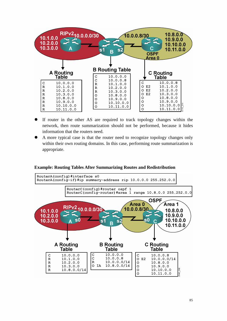
85
� If router in the other AS are required to track topology changes within the
network, then route summarization should not be performed, because it hides information that the routers need.
� A more typical case is that the router need to recognize topology changes only within their own routing domains. In this case, performing route summarization is appropriate.
Example: Routing Tables After Summarizing Routes and Redistribution
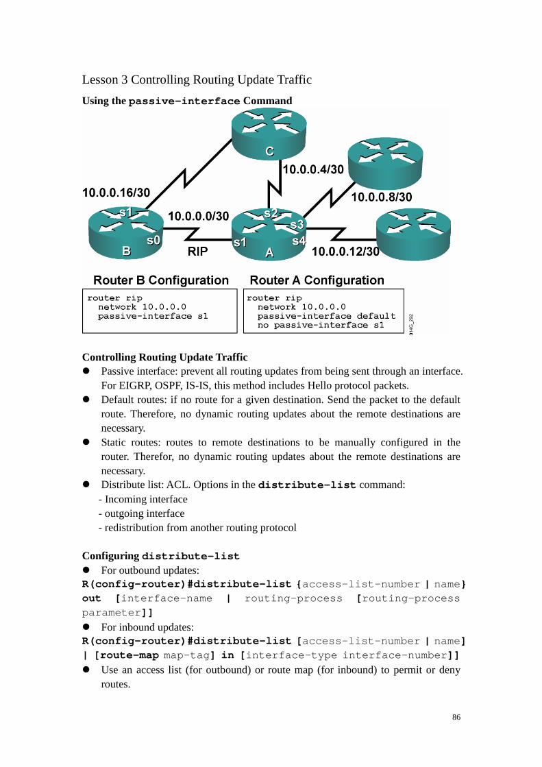
86
Lesson 3 Controlling Routing Update Traffic
Using the passive-interface Command Controlling Routing Update Traffic � Passive interface: prevent all routing updates from being sent through an interface.
For EIGRP, OSPF, IS-IS, this method includes Hello protocol packets. � Default routes: if no route for a given destination. Send the packet to the default
route. Therefore, no dynamic routing updates about the remote destinations are necessary.
� Static routes: routes to remote destinations to be manually configured in the router. Therefor, no dynamic routing updates about the remote destinations are necessary.
� Distribute list: ACL. Options in the distribute-list command: - Incoming interface - outgoing interface - redistribution from another routing protocol
Configuring distribute-list � For outbound updates: R(config-router)#distribute-list { access-list-number | name} out [ interface-name | routing-process [ routing-process parameter]] � For inbound updates: R(config-router)#distribute-list [ access-list-number | name] | [route-map map-tag] in [ interface-type interface-number]] � Use an access list (for outbound) or route map (for inbound) to permit or deny
routes.

87
� Can be applied to transmitted, received, or redistributed routing updates. � Configure a distribute list using an ACL:
- Identify the network address that you want to filter and creat an ACL - Determine whether you want to filter traffic on an incoming interface, an outgoing interface, or routes being redistributed from another routing source. - use the distribute-list out to assign the ACL to filter outgoing routing updates or to assign it to route being redistributed into the protocol. distribute-list out canot be used with link-state routing protocols for blocking outbound link-state advertisements (LSAs) on an interface. - use the distribute-list in to assign the ACL to filter incoming routing updates coming in through an interface. This command prevents most routing protocols from placing the filtered routes in their database. When this command is used with OSPF, the routes are placed in the database but not the routing table. � distribute-list out
� distribute-list in

88
Filtering Routing Updates with a Distribute List � Hides network 10.0.0.0 using interface filtering Controlling Redistribution with Distribute Lists Route Maps � They work like a more sophisticated access list.
- They offer top-down processing. - Once there is a match, leave the route map. � Lines are sequence-numbered for easier editing.
- Insertion of lines - Deletion of lines � Route maps are named rather than numbered for easier documentation. � Match criteria and set criteria can be used, similar to the “if, then” logic in a

89
scripting language. Route Map Applications � Redistribution route filtering: a more sophisticated alternative to distribute lists.
(use set command) � Policy-based routing (PBR): the ability to determine routing policy based on
criteria other than the destination network � BGP policy implementation: the primary tool for defining BGP routing policies Route Map Operation � A list of statements constitutes a route map. � The list is processed top-down like an access list. � The first match found for a route is applied. � The sequence number is used for inserting or deleting specific route map
statements. � An implicit deny at the end of a route map � The match statement may contain multiple references. � Multiple match criteria in the same line use a logical OR. � At least one reference must permit the route for it to be a candidate for
redistribution. � Each vertical match uses a logical AND. � All match statements must permit the route for it to remain a candidate for
redistribution. � Route map permit or deny determines if the candidate will be redistributed. route-map commands � R(config)#route-map map-tag [permit | deny]
[ sequence-number] - defines the route map conditions � R(config-route-map)#match { conditions}
- defines the conditions to match � R(config-route-map)#set { actions}
route-map my_bgp permit 10
{ match statements }
{ match statements }
{ set statements }
{ set statements }
route-map my_bgp deny 20
:: :: ::
:: :: ::
route-map my_bgp permit 30
:: :: ::
:: :: ::

90
- defines the action to be taken on a match � R(config-route)#redistribute protocol [ process id]
route-map map-tag - allows for detailed control of routes being redistributed into a routing protocol.
The match Command

91
The set Command
Route Maps and Redistribution Commands � Routes matching either access list 23 or 29 are redistributed with an OSPF cost of
500, external type 1. � Routes permitted by access list 37 are not redistributed. � All other routes are redistributed with an OSPF cost metric of 5000, external type
2.
Router(config)# router ospf 10
Router(config-router)# redistribute rip route-map r edis-rip
Router(config)#
route-map redis-rip permit 10
match ip address 23 29
set metric 500
set metric-type type-1
route-map redis-rip deny 20
match ip address 37
route-map redis-rip permit 30
set metric 5000
set metric-type type-2
Router(config)#
access-list 23 permit 10.1.0.0 0.0.255.255
access-list 29 permit 172.16.1.0 0.0.0.255
access-list 37 permit 10.0.0.0 0.255.255.255
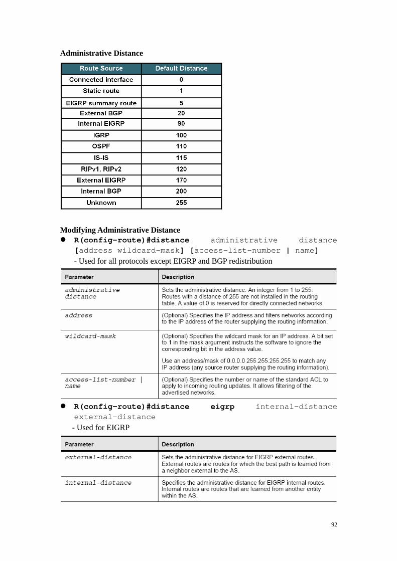
92
Administrative Distance
Modifying Administrative Distance � R(config-route)#distance administrative distance
[ address wildcard-mask] [ access-list-number | name] - Used for all protocols except EIGRP and BGP redistribution
� R(config-route)#distance eigrp internal-distance
external-distance - Used for EIGRP

93
� R(config-route)#distance bgp - Used for BGP
Example: Redistribution Using Administrative Distance � P3R1 or P3R2 learned 10.3.3.0 via RIPv2 and OSPF. But use OSPF because
lower AD even though the path via OSPF might be the longer (worse) path. � Configuration for P3R1 � Configuration for P3R2
router ospf 1
redistribute rip metric 10000 metric-type 1 subnet s
network 172.31.0.0 0.0.255.255 area 0
!
router rip
version 2
redistribute ospf 1 metric 5
network 10.0.0.0
no auto-summary
router ospf 1
redistribute rip metric 10000 metric-type 1 subnet s
network 172.31.3.2 0.0.0.0 area 0
!
router rip
version 2
redistribute ospf 1 metric 5
network 10.0.0.0
no auto-summary

94
� Something needed to be done to prevent suboptimal path. � Change the AD of the redistributed RIP route to ensure that the boundary routers
select the native RIP routes. � P3R1
hostname P3R1
!
router ospf 1
redistribute rip metric 10000 metric-type 1 subnet s
network 172.31.0.0 0.0.255.255 area 0
distance 125 0.0.0.0 255.255.255.255 64
!
router rip
version 2
redistribute ospf 1 metric 5
network 10.0.0.0
no auto-summary
!
access-list 64 permit 10.3.1.0 0.0.0.255
access-list 64 permit 10.3.3.0 0.0.0.255
access-list 64 permit 10.3.2.0 0.0.0.255
access-list 64 permit 10.200.200.31
access-list 64 permit 10.200.200.34
access-list 64 permit 10.200.200.32
access-list 64 permit 10.200.200.33
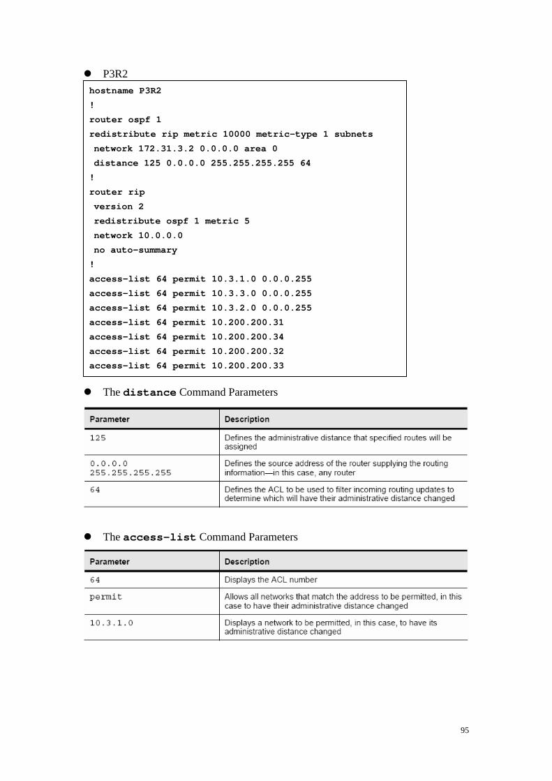
95
� P3R2 � The distance Command Parameters
� The access-list Command Parameters
hostname P3R2
!
router ospf 1
redistribute rip metric 10000 metric-type 1 subnets
network 172.31.3.2 0.0.0.0 area 0
distance 125 0.0.0.0 255.255.255.255 64
!
router rip
version 2
redistribute ospf 1 metric 5
network 10.0.0.0
no auto-summary
!
access-list 64 permit 10.3.1.0 0.0.0.255
access-list 64 permit 10.3.3.0 0.0.0.255
access-list 64 permit 10.3.2.0 0.0.0.255
access-list 64 permit 10.200.200.31
access-list 64 permit 10.200.200.34
access-list 64 permit 10.200.200.32
access-list 64 permit 10.200.200.33

96

97
Lesson 4 Implementing Advanced Cisco IOS Features: Configuring DHCP
DHCP in an Enterprise Network � DHCP is tructured on the Bootstrap Protocol (BOOTP) server and BOOTP
well-know ports in User Datagram Protocol (UDP). Previous to DHCP, IP addresses were manually administered to IP hosts, which was a tedious, error-prone, and labor-intensive process.
Dynamic Host Configuration Protocol

98
� DHCPDISCOVE broadcast message � DHCPOFFER unicast message � DHCPREQUEST broadcast message � DHCPACK unist message � DHCP supports three possible address allocation mechanisms: - Manual: the network administrator assigns the IP address to a specific MAC address. DHCP is used to dispatch the assigned address to the host. - Automatic: the IP address is permanently assigned to a host. - Dynamic: the IP address is assigned to a host for a limited time or until the host explicitly releases the address. This mechanism supports automatic address reuse when the host to which the adderss has been assigned no longer needs the address. Configuring a DHCP Server � R(config)#ip dhcp pool [pool name]
- Enables a DHCP pool for use by hosts � R(config-dhcp)#import all
- imports DNS and WINS information for IPCP � R(config-dhcp)#network [network address] [subnet mask]
- specifies the network and subnet mask of the pool � R(config-dhcp)#default-router [host address]
- specifies the default router for the pool to use

99
� Cisco IOS DHCP Server Command and Parameters
DHCP Server Configuration Example
ipdhcp database ftp://user:[email protected]/r outer-dhcp write-delay 120
ip dhcp excluded-address 172.16.1.100 172.16.1.103
ip dhcp excluded-address 172.16.2.100 172.16.2.103
ip dhcp pool 0
network 172.16.0.0/16
domain-name global.com
dns-server 172.16.1.102 172.16.2.102
netbios-name-server 172.16.2.103 172.16.2.103
default-router 172.16.1.100

100
� Before configuring the Cisco IOS DHCP Server featuer: - Identify an external FTP, TFTP, or Remote Copy Protocol (RCP) server that will be used to store the DHCP binding database. - Identify the IP address range to be assigned by the DHCP server and the IP addresses to be excluded (default routers and other statically assigned addresses within a dynamically assigned range). - Identify DHCP options for devices where necessary, including these:
- Default boot image name - Default routers - DNS servers - Network BISO (NetBIOS) name server - IP telephony options, such as option 150
- Decide on a DNS domain name � The following example, two DHCP address pools are created, one for subnet
172.16.1.0 and on for subnet 172.16.2.0. the host will receive its address from the DHCP server on the closest device. The router determines how to provide the addresses based on the IP address on the router interface.
!
ip dhcp pool 1
network 172.16.1.0/24
domain-name global.com
dns-server 172.16.1.102
netbios-name-server 172.16.2.103
default-router 172.16.1.100 172.16.1.101
lease 30
!
ip dhcp pool 2
network 172.16.2.0/24
domain-name global.com
dns-server 172.16.2.102
netbios-name-server 172.16.2.103
default-router 172.16.2.100 172.16.2.101
lease 30

101
Importing and Autoconfiguration DHCP Client � R(config-if)#ip address dhcp
- Enables a Cisco IOS device to obtain an IP address dynamically from a DHCP server
Helper Addressing Overview � Routers do not forward broadcasts, by default. � Helper address provides selective connectivity. � The Cisco IOS DHCP relay agent is enabled on an interface only when the ip
helper-address is configured.
Central Router
ip dhcp-excluded address 10.0.0.1 10.0.0.5
ip dhcp pool central
network 10.0.0.0 255.255.255.0
default-router 10.0.0.1 10.0.0.5
domain-name central.com
dns-server 10.0.0.2
interface fastethernet0/0
ip address 10.0.0.1 255.255.255.0
Remote Router
ip dhcp pool client
network 20.0.0.0 255.255.255.0
ip dhcp-excluded address 20.0.0.2
default-router 20.0.0.2
import all
interface fastethernet0/0
ip address dhcp

102
� The DHCP relay agent is any host that forwards DHCP packets between clients and servers. Relay agents are used to forward requests and replies between clients and servers when they are not on the same physical subnet.
� Relay agents receive DHCP messages and then generate a new DHCP message to send out on another interface.
Why Use a Helper Address? � Sometimes clients do not know the server address. � Helpers change broadcast to unicast to reach server. � DHCP clients use UDP broadcasts to send their initial DHCPDISCOVER
message, because they do not have information about the network to which they are attached.
� If the client is on a network that does not include a server, UDP broadcasts are normally not forwarded by the attached router.
� The ip helper-address command causes the UDP broadcast to be changed to a unicast and forwarded out another interface to a unicast IP address specified by the command.
� The relay agent sets the gateway address (giaddr field of the DHCP packet) and, if configured, adds the relay agent information option (option 82) in the packet and forwards it to the DHCP server. The reply from the server is forwarded back to the client after removing option 82.
IP Helper Address Commands � R(config)#ip helper-address address
- Enables forwarding and specifies destination address for main UDP broadcast packets - Changes destination address from broadcast to unicast or directed broadcast address � R(config)#ip forward-protocol {udp [ port]}
- Specifies which protocols will be forwarded

103
Multiple Servers: Remote Networks � The UDP well-known ports identified by default forwarding UDP services are:
- Time: 37 - TACACS: 49 - DNS: 53 - BOOTP/DHCP server: 67 - BOOTP/DHCP client: 68 - TFTP: 69 - NetBIOS name service: 137 - NetBIOS datagram service: 138
Ports can be eliminated from the forwarding service with the no ip forward-protocol command, and ports can be added to the forwarding service with the ip forward-protocol command. The following is an example: This configuration would cause time and NetBIOS ports to not be forwarded, and UDP port 8000 would be added to the forwarded list.
!
interface fastethernet0/0
ip address 10.3.3.3 255.255.255.0
ip helper-address 10.1.1.1
no ip forward-protocol upd 137
no ip forward-protocol upd 138
no ip forward-protocol upd 37
ip forward-protocol upd 8000

104
Relay Agent Option Support � When you use the ip dhcp relay information option command, the
relay agent adds the circuit identifier suboption and the remote ID suboption to the relay agent information and forwards them to a DHCP server. The following explains the DHCP relay services process: 1. The DHCP client generates a DHCP request and broadcasts it on the network. 2. The DHCP relay agent intercepts the broadcast DHCP request packet and inserts the relay agent information option (82) in the packet. The relay agent option contains the related suboptions. 3. The DHCP relay agent unicasts the DHCP packet to the DHCP server. 4. The DHCP server receives the packet and uses the suboptions to assign IP addresses and other configuration parameters and forwards them back to the client. 5. The suboption fields are stripped off of the packet by the relay agent while forwarding to the client.

105
� Description of Option Support Commands and Parameters

106
DHCP Verification Commands � R#show ip dhcp database
- Displays recent activity on the DHCP database � R#show ip dhcp server statistics
- Show count information about statistics and messages sent and received � R#show ip route dhcp
- Displays routes added to the routing table by DHCP � R#show ip dhcp server {events | packets | linkage}
- Enables debugging on the DHCP server Description of DHCP Verification Commands and Parameters

107
Module 6 Implementing BGP
Lesson 1 Explaining BGP Concepts and Terminology
BGP – Border Gateway Protocol Using BGP to Connect to the Internet � If only one ISP, do not need BGP. If multiple ISPs, use BGP, because it allows
manipulation of path attributs so that the optimal path can be selected. � IGP: a routing protocol that exchanges routing information within an AS. RIP,
IGRP, OSPF, IS-IS, and EIGRP are examples of IGPs.. � EGP: a routing protocol that exchanges routing information between different
automous systems. BGP is an example of EGP. � BGP is an interdomain routing protocol (IDRP), also know as an EGP. � EBGP: BGP is running between routers in different autonomous systems � IBGP: BGP is running between routers in the same autonomous systems Multihoming � Connecting to two or more ISPs to increase the following:
- Reliability: If one ISP or connection fails, there is still Internet access. - Performance: Better path selection to common Internet destinations. � Perform multihoming with BGP, three common ways to do:
- Each ISP passes only a default route to the AS: The default route is passed to the internal routers. - Each ISP passes only a default route and provider-owned specific routes to the AS: These routes may be passed to internal routers, or all internal routers in the transit path can run BGP and pass these routes between them. - Each ISP passes all routes to the AS: All internal routers in the transit path run BGP and pass these routes between them.
Example: default Routes from All Providers

108
Default Routes from All Providers and Partial Table Example: Full Routes from All Providers BGP Autonomous Systems � An AS is a collection of networks under a single technical administration. � IGPs operate within an AS. � BGP is used between autonomous systems. � Exchange of loop-free routing information is guaranteed. � AS numbers: 16-bit numbers from 1 to 65535. private: 64512 - 65535 BGP Path-Vector Routing � IGPs announce networks and describe the metric to reach those networks. � BGP announces paths and the networks that are reachable at the end of the path.

109
BGP describes the path by using attributes, which are similar to metrics. � BGP allows administrators to define policies or rules for how data will flow
through the autonomous systems. BGP Routing Ploicies � BGP can support any policy conforming to the hop-by-hop (AS-by-AS) routing
paradigm. BGP Characteristics � BGP is most appropriate when at least one of the following conditions exists:
- An AS allows packets to transit through it to reach other autonomous systems (for example, it is a service provider). - An AS has multiple connections to other autonomous systems. - Routing policy and route selection for traffic entering and leaving the AS must be manipulated. � BGP is not always appropriate. Do not have to use BGP if you have one of the
following conditions: - Limited understanding of route filtering and BGP path selection process - A single connection to the Internet or another AS - Lack of memory or processor power to handle constant updates on BGP routers � BGP is a path-vector protocol with the following enhancements over distance
vector protocols: - Reliable updates: BGP runs on top of TCP (port 179) - Incremental, triggered updates only - Periodic keepalive messages to verify TCP connectivity (every 60 seconds) - Rich metrics (called path vectors or attributes) - Designed to scale to huge internetworks (for example, the Internet) � NOTE: BGP use TCP as its transport layer. OSPF, IGRP, EIGRP reside dierctly
above the IP layer and RIP use UDP BGP Databases � Neighbor table
- List of BGP neighbors � BGP table (forwarding database)
- List of all networks learned from each neighbor - Can contain multiple paths to destination networks - Contains BGP attributes for each path � IP routing table
- List of best paths to destination networks � AD: EBGP 20; IBGP: 200 BGP Message Types � Open
- Includes holdtime and BGP router ID

110
� Keepalive � Update
- Information for one path only (could be to multiple networks) - Includes path attributes and networks � Notification
- When error is detected - BGP connection is closed after being sent

111
Lesson 2 Explaining EBGP and IBGP
Peers = Neighbors � A “BGP peer,” also known as a “BGP neighbor,” is a specific term that is used for
BGP speakers that have established a neighbor relationship. � Any two routers that have formed a TCP connection to exchange BGP routing
information are called BGP peers or BGP neighbors. � BGP peer must be configured with a BGP neighbor command. External BGP � When BGP is running between neighbors that belong to different autonomous
systems, it is called EBGP. � EBGP neighbors, by default, need to be directly connected. Internal BGP � When BGP is running between neighbors within the same AS, it is called IBGP. � The neighbors do not have to be directly connected.

112
IBGP in a Transit AS (ISP) � Redistributing BGP into an IGP (OSPF in this example) is not recommended. � Instead, run IBGP on all routers. IBGP in a NonTransit AS � By default, routes learned via IBGP are never propagated to other IBGP peers, so
they need full-mesh IBGP. Routing Issues if BGP Is Not on in All Routers in Transit Path � Router C will drop the packet to network 10.0.0.0. Router C is not running IBGP;
therefore, it has not learned about the route to network 10.0.0.0 from router B. � In this example, router B and router E are not redistributing BGP into OSPF.

113
Lesson 3 Configuring Basic IBGP Operations
BGP Commands � R(config)#router bgp autonomous-system
- This command enters router configuration mode only; subcommands must be entered to activate BGP. - Only one instance of BGP can be configured on the router at a single time. - The autonomous system number identifies the autonomous system to which the router belongs. (the local AS number) - The autonomous system number in this command is compared to the autonomous system numbers listed in neighbor statements to determine if the neighbor is an internal or external neighbor.
BGP neighbor remote-as Commands � R(config-router)#neighbor { ip-address | peer-group-name}
remote-as autonomous-system
- The neighbor command activates a BGP session with this neighbor. - The IP address that is specified is the destination address of BGP packets going to this neighbor. - This router must have an IP path to reach this neighbor before it can set up a BGP relationship. - The remote-as option shows what AS this neighbor is in. This AS number is used to determine if the neighbor is internal or external. - This command is used for both external and internal neighbors.
Example: BGP neighbor Commands

114
BGP neighbor shutdown Commands � R(config-router)#neighbor { ip-address | peer-group-name}
shutdown
- Administratively brings down a BGP neighbor - Used for maintenance and policy changes to prevent route flapping � R(config-router)#no neighbor { ip-address |
peer-group-name} shutdown
- Re-enables a BGP neighbor that has been administratively shut down BGP Issues with Source IP Address � When creating a BGP packet, the neighbor statement defines the destination IP
address and the outbound interface defines the source IP address. � When a BGP packet is received for a new BGP session, the source address of the
packet is compared to the list of neighbor statements: - If a match is found, a relationship is established. - If no match is found, the packet is ignored. � Make sure that the source IP address matches the address that the other router has
in its neighbor statement. Example: IBGP Peering Issue � If router D uses neighbor 10.3.3.1 remote-as 65102 , but router A is
sending the BGP packets to router D via router B, the source IP address will be 10.1.1.1. Therefore, the IBGP session between router A and router D cannot be established.
� A solution to this problem is to establish the IBGP session using a loopback interface when there are multiple paths between the IBGP neighbors.

115
BGP neighbor update-source Command � R(config-router)#neighbor { ip-address | peer-group-name}
update-source interface-type interface-number
- This command allows the BGP process to use the IP address of a specified interface as the source IP address of all BGP updates to that neighbor. - A loopback interface is usually used, because it will be available as long as the router is operational. - The IP address used in the neighbor command on the other router will be the destination IP address of all BGP updates and should be the loopback interface of this router. - The neighbor update-source command is normally used only with IBGP neighbors. - The address of an EBGP neighbor must be directly connected by default; the loopback of an EBGP neighbor is not directly connected.
Example: BGP Using Loopback Address � The neighbor update-source command should be used on both routers. BGP neighbor ebgp-multihop Command � R(config-router)#neighbor { ip-address | peer-group-name}
ebgp-multihop [ ttl]
- This command allows the router to accept and attempt BGP connections to external peers residing on networks that are not directly connected. - This command increases the default of one hop for EBGP peers by changing the default Time to Live (TTL) value of 1. (default: TTL is set to 255) - It allows routes to the EBGP loopback address (which will have a hop count greater than 1).

116
Example: BGP Using Loopback Address � BGP is not designed to perform load balancing; paths are chosen because of
policy, not based on bandwidth. BGP will choose only a single best path. Using the loopback addresses and the neighbor ebgp-multihop command as shown in this example allows load balancing, as well as redundancy, across the two paths between the autonomous systems.
Next-Hop Behavior � BGP is an AS-by-AS routing protocol, not a router-by-router routing protocol. � In BGP, the next hop does not mean the next router; it means the IP address to
reach the next AS. � For EBGP, the default next hop is the IP address of the neighbor router that sent
the update. � For IBGP, the BGP protocol states that the next hop advertised by EBGP should
be carried into IBGP. Example: Next-Hop Behavior � Router A advertises network 172.16.0.0 to router
B in EBGP, with a next hop of 10.10.10.3. � Router B advertises 172.16.0.0 in IBGP to router
C, keeping 10.10.10.3 as the next-hop address.

117
BGP neighbor next-hop-self Command � R(config-router)#neighbor { ip-address | peer-group-name}
next-hop-self
- Forces all updates for this neighbor to be advertised with this router as the next hop. - The IP address used for the next-hop-self option will be the same as the source IP address of the BGP packet.
Example: next-hop-self Configuration Example: Next Hop on a Multiaccess Network

118
� Router B advertises network 172.30.0.0 to router A in EBGP with a next hop of 10.10.10.2, not 10.10.10.1. This avoids an unnecessary hop.
� BGP is being efficient by informing AS 64520 of the best entry point into AS 65000 for network 172.30.0.0.
� Router B in AS 65000 also advertises to AS 64520 that the best entry point for each network in AS 64600 is the next hop of router C because that is the best path to move through AS 65000 to AS 64600.
Using a Peer Group � R(config-router)#neighbor peer-group-name peer-group
- This command creats a peer group. � R(config-router)#neighbor ip-address peer-group
peer-group-name
- This command defines a template with parameters set for a group of neighbors instead of individually. - This command is useful when many neighbors have the same outbound policies. - Members can have a different inbound policy. - Updates are generated once per peer group. - Configuration is simplified. - Must enter the neighbor peer-group-name peer-group command before the router will accept this command.
Example: Using a Peer Group
router bgp 65100
neighbor 192.168.24.1 remote-as 65100
neighbor 192.168.24.1 update-source Loopback 0
neighbor 192.168.24.1 next-hop-self
neighbor 192.168.24.1 distribute-list 20 out
neighbor 192.168.25.1 remote-as 65100
neighbor 192.168.25.1 update-source Loopback 0
neighbor 192.168.25.1 next-hop-self
neighbor 192.168.25.1 distribute-list 20 out
neighbor 192.168.26.1 remote-as 65100
neighbor 192.168.26.1 update-source Loopback 0
neighbor 192.168.26.1 next-hop-self
neighbor 192.168.26.1 distribute-list 20 out
router bgp 65100
neighbor internal peer-group
neighbor internal remote-as 65100
neighbor internal update-source Loopback 0
neighbor internal next-hop-self
neighbor internal distribute-list 20 out
neighbor 192.168.24.1 peer-group internal
neighbor 192.168.25.1 peer-group internal
neighbor 192.168.26.1 peer-group internal
Router C Without a Peer Group
Router C Using a Peer Group

119
BGP network Command � R(config-router)#network network-number [mask
network-mask] [route-map map-tag]
- This command tells BGP what network to advertise. - The command does not activate the protocol on an interface. - Without a mask option, the command advertises classful networks. If a subnet of the classful network exists in a routing table, the classful address is announced. - With the mask option, BGP looks for an exact match in the local routing table before announcing the route.
� The neighbor command tells BGP where to advertise, and the network
command tells BGP what to advertise. Example: BGP network Command � R(config-router)#network 192.168.1.1 mask 255.255.255.0
- The router looks for exactly 192.168.1.1/24 in the routing table, but cannot find it, so it will not announce anything. � R(config-router)#network 192.168.0.0 mask 255.255.0.0
- The router looks for exactly 192.168.0.0/16 in the routing table. - If the exact route is not in the table, you can add a static route to null0 so that the route can be announced.
BGP Synchronization � Synchronization rule: Do not use or advertise to an external neighbor a route
learned by IBGP until a matching route has been learned from an IGP. In other words, BGP and the IGP must be synchronized before the networks learned from an IBGP neighbor can be used. - Ensures consistency of information throughout the AS - Safe to have it off only if all routers in the transit path in the AS are running full-mesh IBGP; off by default in Cisco IOS software release 12.2(8)T and later � R(config-router)#no synchronization
- Disables BGP synchronization so that a router will advertise routes in BGP without learning them in an IGP � R(config-router)#synchronization
- Enables BGP synchronization so that a router will not advertise routes in BGP until it learns them in an IGP � BGP synchronization is unnecessary in some situations. It is safe to have BGP

120
synchronization off only if all routers in the transit path in the AS are running full-mesh IBGP.
� Use synchronization if there are routers in the BGP transit path in the AS that are not running BGP (therefore, the routers do not have full-mesh IBGP within the AS).
� In the past, the best practice was to redistribute BGP into the IGP running in an AS, so that IBGP was not needed in every router in the transit path. In this case, synchronization was needed to make sure that packets did not get lost, so synchronization was on by default. As the Internet grew, the number of routes in the BGP table became too much for the IGPs to handle, so the best practice changed to not redistributing BGP into the IGP, but instead using IBGP on all routers in the transit path. In this case, synchronization is not needed; it is now off by default.
Example: BGP Synchronization � If synchronization is on, then:
- Routers A, C, and D would not use or advertise the route to 172.16.0.0 until they receive the matching route via an IGP. - Router E would not hear about 172.16.0.0. � If synchronization is off (the default), then:
- Routers A, C, and D would use and advertise the route that they receive via IBGP; router E would hear about 172.16.0.0. - If router E sends traffic for 172.16.0.0, routers A, C, and D would route the packets correctly to router B. � In modern autonomous systems, because the size of the Internet routing table is
large, redistributing from BGP into an IGP is not scalable; therefore, most modern autonomous systems run full-mesh IBGP and do not require synchronization. Advanced BGP configuration methods, for example, using route reflectors and confederations, reduce the full-mesh requirements.

121
Example: BGP Configuration
1. RouterB(config)# router bgp 65000
2. RouterB(config-router)# neighbor 10.1.1.2 remote-as 64520
3. RouterB(config-router)# neighbor 192.168.2.2 remote-as 65000
4. RouterB(config-router)# neighbor 192.168.2.2 update-source Loopback 0
5. RouterB(config-router)# neighbor 192.168.2.2 next-hop-self
6. RouterB(config-router)# network 172.16.10.0 mask 255.255.255.0
7. RouterB(config-router)# network 192.168.1.0
8. RouterB(config-router)# network 192.168.3.0
9. RouterB(config-router)# no synchronization

122
BGP States When establishing a BGP session, BGP goes through the following states: 1. Idle: Router is searching routing table to see whether a route exists to reach the
neighbor. 2. Connect: Router found a route to the neighbor and has completed the three-way
TCP handshake. 3. Open sent: Open message sent, with the parameters for the BGP session. 4. Open confirm: Router received agreement on the parameters for establishing
session. - Alternatively, router goes into active state if no response to open message
5. Established: Peering is established; routing begins. BGP Established and Idle States � Idle: The router in this state cannot find the address of the neighbor in the routing
table. Check for an IGP problem. Is the neighbor announcing the route? - The router is idle because of one of the following scenarios:
- It is waiting for a static route to that IP address or network to be configured. - It is waiting for the local routing protocol (IGP) to learn about this network through an advertisement from another router.
- Check these two conditions first to correct this problem: - Ensure that the neighbor announces the route in its local routing protocol (IGP). - Verify that you have not entered an incorrect IP address in the neighbor statement.
� Established: The established state is the proper state for BGP operations. In the output of the show ip bgp summary command, if the state column has a number, then the route is in the established state. The number is how many routes have been learned from this neighbor.
Example: show ip bgp neighbors Command
RouterA#sh ip bgp neighbors
BGP neighbor is 172.31.1.3, remote AS 64998, exter nal link
BGP version 4, remote router ID 172.31.2.3
BGP state = Established , up for 00:19:10
Last read 00:00:10, last write 00:00:10, hold tim e is 180, keepalive
interval is 60 seconds
Neighbor capabilities:
Route refresh: advertised and received(old & ne w)
Address family IPv4 Unicast: advertised and rec eived
Message statistics:
InQ depth is 0
OutQ depth is 0
Sent Rcvd
Opens: 7 7
Notifications: 0 0
Updates: 13 38
<output omitted>

123
BGP Active State Troubleshooting � Active: The router has sent an open packet and is waiting for a response. The
state may cycle between active and idle. The neighbor may not know how to get back to this router because of the following reasons: - Neighbor does not have a route to the source IP address of the BGP open packet generated by this router. - Neighbor is peering with the wrong address. - Neighbor does not have a neighbor statement for this router. - AS number is misconfiguration. – the most common problem
Example: BGP Active State Troubleshooting � At the router with the wrong remote AS number:
%BGP-3-NOTIFICATION: sent to neighbor 172.31.1.3 2/2 (peer in wrong AS) 2 bytes FDE6 FFFF FFFF FFFF FFFF FFFF FFFF FFFF FFFF 002D 0104 FDE6 00B4 AC1F 0203 1002 0601 0400 0100 0102 0280 0002 0202 00 � At the remote router:
%BGP-3-NOTIFICATION: received from neighbor 172.31.1.1 2/2 (peer in wrong AS) 2 bytes FDE6
Example: BGP Peering � The show ip bgp summary command is one way to verify the neighbor
relationship.
RouterA# show ip bgp summary
BGP router identifier 10.1.1.1, local AS number 650 01
BGP table version is 124, main routing table versio n 124
9 network entries using 1053 bytes of memory
22 path entries using 1144 bytes of memory
12/5 BGP path/bestpath attribute entries using 1488 bytes of memory
6 BGP AS-PATH entries using 144 bytes of memory
0 BGP route-map cache entries using 0 bytes of memo ry
0 BGP filter-list cache entries using 0 bytes of me mory
BGP using 3829 total bytes of memory
BGP activity 58/49 prefixes, 72/50 paths, scan inte rval 60 secs
Neighbor V AS MsgRcvd MsgSent TblVer InQ OutQ Up/Down State/PfxRcd
10.1.0.2 4 65001 11 11 124 0 0 00:02:28 8
172.31.1.3 4 64998 21 18 124 0 0 00:01:13 6
172.31.11.4 4 64999 11 10 124 0 0 00:01:11 6

124
BGP Neighbor Authentication � R(config-router)#neighbor { ip-address | peer-group-name }
password string
- BGP authentication uses MD5. - Configure a key (password); router generates a message digest, or hash, of the key and the message. - Message digest is sent; key is not sent. - Router generates and checks the MD5 digest of every segment sent on the TCP connection. Router authenticates the source of each routing update packet that it receives
� If a router has a password configured for a neighbor, but the neighbor router does
not: %TCP-6-BADAUTH: No MD5 digest from 10.1.0.2(179) to 10.1.0.1(20236) � If the two routers have different passwords configured:
%TCP-6-BADAUTH: Invalid MD5 digest from 10.1.0.1(12293) to 10.1.0.2(179) Example: BGP Neighbor Authentication

125
Example: show ip bgp Command Example: show ip bgp rib-failure Command � Displays networks that are not installed in the RIB and the reason that they were
not installed Clearing the BGP Session � When policies such as access lists or attributes are changed, the change takes
effect immediately, and the next time that a prefix or path is advertised or received, the new policy is used. It can take a long time for the policy to be applied to all networks.
� You must trigger an update to ensure that the policy is immediately applied to all affected prefixes and paths.
� Ways to trigger an update: - Hard reset - Soft reset - Route refresh
RouterA# show ip bgp
BGP table version is 14, local router ID is 172.31. 11.1
Status codes: s suppressed, d damped, h history, * valid, > best, i - internal,
r RIB-failure, S Stale
Origin codes: i - IGP, e - EGP, ? - incomplete
Network Next Hop Metric LocP rf Weight Path
*> 10.1.0.0/24 0.0.0.0 0 32768 i
* i 10.1.0.2 0 100 0 i
*> 10.1.1.0/24 0.0.0.0 0 32768 i
*>i10.1.2.0/24 10.1.0.2 0 1 00 0 i
*> 10.97.97.0/24 172.31.1.3 0 64998 64997 i
* 172.31.11.4 0 64999 64997 i
* i 172.31.11.4 0 100 0 64999 64997 i
*> 10.254.0.0/24 172.31.1.3 0 0 64998 i
* 172.31.11.4 0 64999 64998 i
* i 172.31.1.3 0 100 0 64998 i
r> 172.31.1.0/24 172.31.1.3 0 0 64998 i
r 172.31.11.4 0 64999 64998 i
r i 172.31.1.3 0 100 0 64998 i
*> 172.31.2.0/24 172.31.1.3 0 0 64998 i
<output omitted>
RouterA# show ip bgp rib-failure
Network Next Hop RI B-failure RIB-NH Matches
172.31.1.0/24 172.31.1.3 Higher admin distance n/a
172.31.11.0/24 172.31.11.4 Higher admin distance n/a

126
Hard Reset of BGP Sessions � R#show ip bgp *
- Resets all BGP connections with this router. - Entire BGP forwarding table is discarded. - BGP session makes the transition from established to idle; everything must be relearned. � R#clear ip bgp [ neighbor-address]
- Resets only a single neighbor. - BGP session makes the transition from established to idle; everything from this neighbor must be relearned. - Less severe than clear ip bgp *.
Soft Reset Outbound � R#clear ip bgp {*| neighbor-address} [soft out]
- Routes learned from this neighbor are not lost. - This router resends all BGP information to the neighbor without resetting the connection. - The connection remains established. - This option is highly recommended when you are changing outbound policy. - The soft out option does not help if you are changing inbound policy.
Inbound Soft Reset � R(config-router)#neighbor [ ip-address]
soft-reconfiguration inbound - This router stores all updates from this neighbor in case the inbound policy is changed. - The command is memory-intensive. � R#clear ip bgp {*| neighbor-address} soft in
- Uses the stored information to generate new inbound updates Route Refresh: Dynamic Inbound Soft Reset � R#clear ip bgp {*| neighbor-address} [soft in | in]
- Routes advertised to this neighbor are not withdrawn. - Does not store update information locally. - The connection remains established. - Introduced in Cisco IOS software release 12.0(2)S and 12.0(6)T.
NOTE: The clear ip bgp soft command performs a soft reconfiguration of both inbound and outbound updates.

127
debug ip bgp updates Command
RouterA# debug ip bgp updates
Mobile router debugging is on for address family: I Pv4 Unicast
RouterA# clear ip bgp 10.1.0.2
<output omitted>
*Feb 24 11:06:41.309: %BGP-5-ADJCHANGE: neighbor 10 .1.0.2 Up
*Feb 24 11:06:41.309: BGP(0): 10.1.0.2 send UPDATE (format) 10.1.1.0/24,
next 10.1.0.1, metric 0, path Local
*Feb 24 11:06:41.309: BGP(0): 10.1.0.2 send UPDATE (prepend, chgflags: 0x0)
10.1.0.0/24, next 10.1.0.1, metric 0, path Local
*Feb 24 11:06:41.309: BGP(0): 10.1.0.2 NEXT_HOP part 1 net 10.97.97.0/24,
next 172.31.11.4
*Feb 24 11:06:41.309: BGP(0): 10.1.0.2 send UPDATE (format) 10.97.97.0/24,
next 172.31.11.4 , metric 0, path 64999 64997
*Feb 24 11:06:41.309: BGP(0): 10.1.0.2 NEXT_HOP par t 1 net 172.31.22.0/24,
next 172.31.11.4
*Feb 24 11:06:41.309: BGP(0): 10.1.0.2 send UPDATE (format) 172.31.22.0/24,
next 172.31.11.4, metric 0, path 64999
<output omitted>
*Feb 24 11:06:41.349: BGP(0): 10.1.0.2 rcvd UPDATE w/ attr: nexthop 10.1.0.2,
origin i, localpref 100, metric 0
*Feb 24 11:06:41.349: BGP(0): 10.1.0.2 rcvd 10.1.2.0/24
*Feb 24 11:06:41.349: BGP(0): 10.1.0.2 rcvd 10.1.0.0/24

128
Lesson 4 Selecting a BGP Path
BGP Path Attributes � BGP metrics are called path attributes. � Characteristics of path attributes include:
- Well-known versus optional - Mandatory versus discretionary - Transitive versus nontransitive - Partial � Path attributes:
- Well-known mandatory - Well-known discretionary - Optional transitive - Optional nontransitive - Only optional transitive attributes can be marked as partial.
Well-Known Attributes � Well-known attributes
- Must be recognized by all compliant BGP implementations - Are propagated to other neighbors � Well-known mandatory attributes
- Must be present in all update messages � Well-known discretionary attributes
- May be present in update messages Optional Attributes � Optional attributes
- They are recognized by some implementations (could be private); but expected not to be recognized by all BGP routers. - Recognized optional attributes are propagated to other neighbors based on their meaning. � Optional transitive attributes
- If not recognized, marked as partial and propagated to other neighbors � Optional nontransitive attributes
- Discarded if not recognized BGP Attributes � Well-known mandatory attribute
- AS path - Next-hop - Origin � Well-known discretionary attribute
- Local preference - Atomic aggregate

129
� Optional transitive attribute - Aggregator
� Optional nontransitive attribute - Multi-exit discriminator (MED)
AS Path Attribute � A list of autonomous systems that a
route has traversed: - For example, on router B, the path to 192.168.1.0 is the AS sequence (65500, 64520). - A to B: (65500, 65000) - C to A: (64520) - C to B: (65000) � The AS path attribute is well-known,
mandatory. Next-Hop Attribute � The IP address of the next AS to reach
a given network: - Router A advertises network 172.16.0.0 to router B in EBGP, with a next hop of 10.10.10.3. - Router B advertises 172.16.0.0 in IBGP to router C, keeping 10.10.10.3 as the next-hop address. � The next-hop attribute is well-known,
mandatory. Origin Attribute � IGP (i): network command � EGP (e): Redistributed from EGP � Incomplete (?): Redistributed from IGP or static � The origin attribute informs all autonomous systems in the internetwork how the
prefixes were introduced into BGP. � The origin attribute is well-known, mandatory.

130
Example: Origin Attribute Local Preference Attribute � Paths with highest local preference value are preferred:
- Local preference is used to advertise to IBGP neighbors about how to leave their AS. - The local preference is sent to IBGP neighbors only (that is, within the AS only). - The local preference attribute is well-known and discretionary. - Default value is 100.
RouterA# show ip bgp
BGP table version is 14, local router ID is 172.31. 11.1
Status codes: s suppressed, d damped, h history, * valid, > best, i - internal,
r RIB-failure, S Stale
Origin codes: i - IGP, e - EGP, ? - incomplete
Network Next Hop Metric Loc Prf Weight Path
*> 10.1.0.0/24 0.0.0.0 0 32768 i
* i 10.1.0.2 0 100 0 i
*> 10.1.1.0/24 0.0.0.0 0 32768 i
*>i10.1.2.0/24 10.1.0.2 0 1 00 0 i
*> 10.97.97.0/24 172.31.1.3 0 64998 64997 i
* 172.31.11.4 0 64999 64997 i
* i 172.31.11.4 0 100 0 64999 64997 i
*> 10.254.0.0/24 172.31.1.3 0 0 64998 i
* 172.31.11.4 0 64999 64998 i
* i 172.31.1.3 0 100 0 64998 i
r> 172.31.1.0/24 172.31.1.3 0 0 64998 i
r 172.31.11.4 0 64999 64998 i
r i 172.31.1.3 0 100 0 64998 i
*> 172.31.2.0/24 172.31.1.3 0 0 64998 i
<output omitted>

131
MED Attribute � The paths with the lowest MED (also
called the metric) value are the most desirable: - MED is used to advertise to EBGP neighbors how to exit their AS to reach networks owned by this AS. - By default, a router compares the MED attribute only for paths from neighbors in the same AS. � The MED attribute is optional and
nontransitive. � MED influences inbound traffic to an AS, and local preference influences
outbound traffic from an AS. NOTE: The MED attribute means that BGP is the only protocol that can affect how routes are sent into an AS. Weight Attribute (Cisco Only) � Paths with the highest weight value are preferred � Weight not sent to any BGP neighbors; local to this router only � The weight can have a value from 0 to 65535. Paths that the router originates
have a weight of 32768 by default, and other paths have a weight of 0 by default. BGP Path Selection � The BGP forwarding table usually has multiple paths from which to choose for
each network. � BGP is not designed to perform load balancing:
- Paths are chosen because of policy. - Paths are not chosen based on bandwidth. � The BGP selection process eliminates any multiple paths through attrition until a
single best path is left. � That best path is submitted to the routing table manager process and evaluated
against the methods of other routing protocols for reaching that network (using administrative distance).
132
� The route from the source with the lowest administrative distance is installed in the routing table.
Route Selection Decision Process � Consider only (synchronized) routes with no AS loops and a valid next hop, and
then: 1. Prefer highest weight (local to router). 2. Prefer highest local preference (global within AS). 3. Prefer route originated by the local router (next hop = 0.0.0.0). 4. Prefer shortest AS path. 5. Prefer lowest origin code (IGP < EGP < incomplete). 6. Prefer lowest MED (exchanged between autonomous systems). 7. Prefer EBGP path over IBGP path. 8. Prefer the path through the closest IGP neighbor. 9. Prefer oldest route for EBGP paths. 10. Prefer the path with the lowest neighbor BGP router ID. 11. Prefer the path with the lowest neighbor IP address.
� The MED comparison is made only if the neighboring AS is the same for all routes considered, unless the bgp always-compare-med command is enabled.

133
Lesson 5 Using Route Maps to Manipulate Basic BGP Paths
BGP Is Designed to Implement Policy Routing � BGP is designed for manipulating routing paths. Changing BGP Local Preference For All Routes � Local preference is used in these ways:
- Within an AS between IBGP speakers - To determine the best path to exit the AS to reach an outside network - Set to 100 by default; higher values preferred � R(config-router)#bgp default local-preference value
- This command changes the default local preference value. - All routes advertised to an IBGP neighbor have the local preference set to the value specified. - value: Local preference value from 0 to 4294967295. A higher value is more preferred. � If an EBGP neighbor receives a local preference value, EBGP neighbor ignores it. Local Preference Case Study � The best path for router C to 65003:
- Steps 1 and 2 look at weight and local preference and use the default settings of weight equaling 0 and local preference equaling 100 for all routes that are learned from the IBGP neighbors of A and B. - Step 3 does not help decide the best path because the three AS routes are not owned or originated by AS 65001.
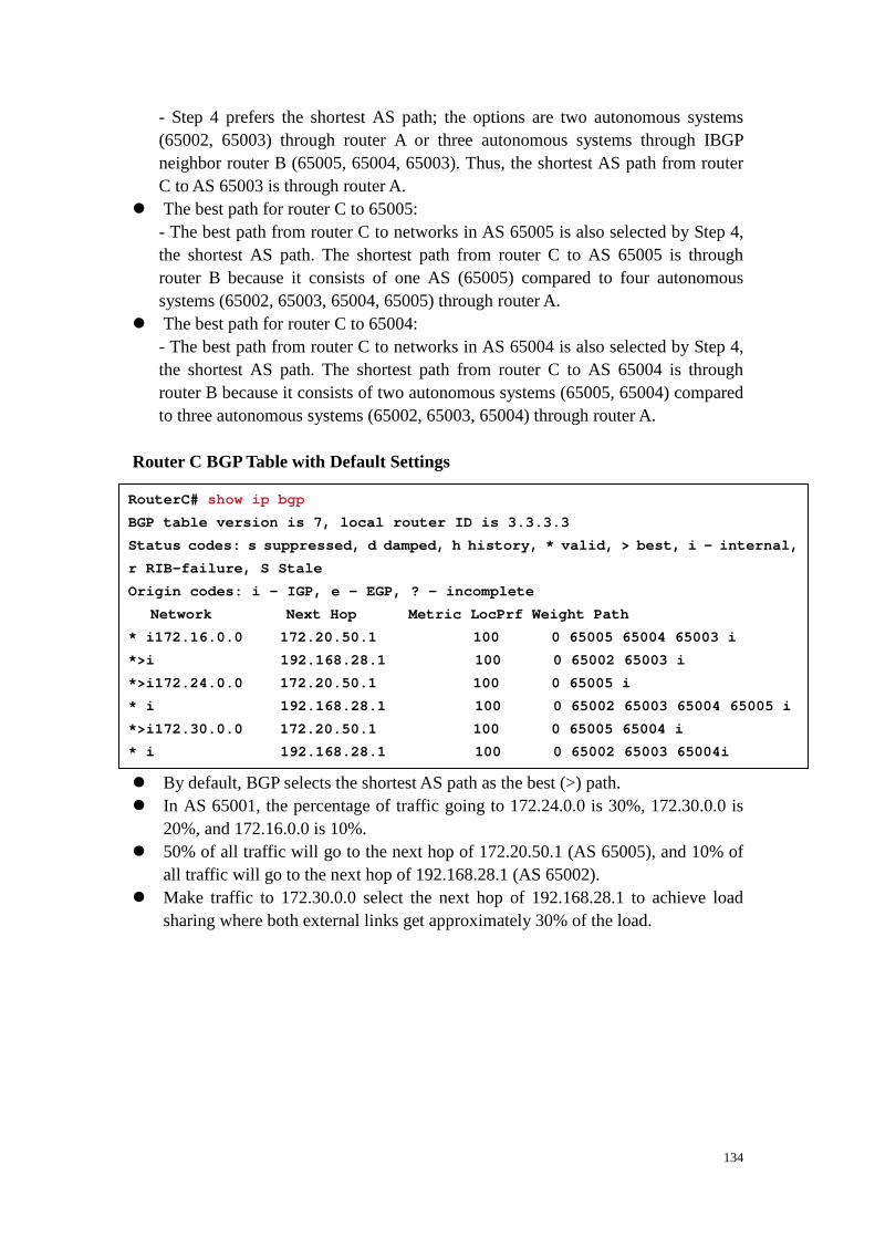
134
- Step 4 prefers the shortest AS path; the options are two autonomous systems (65002, 65003) through router A or three autonomous systems through IBGP neighbor router B (65005, 65004, 65003). Thus, the shortest AS path from router C to AS 65003 is through router A. � The best path for router C to 65005:
- The best path from router C to networks in AS 65005 is also selected by Step 4, the shortest AS path. The shortest path from router C to AS 65005 is through router B because it consists of one AS (65005) compared to four autonomous systems (65002, 65003, 65004, 65005) through router A. � The best path for router C to 65004:
- The best path from router C to networks in AS 65004 is also selected by Step 4, the shortest AS path. The shortest path from router C to AS 65004 is through router B because it consists of two autonomous systems (65005, 65004) compared to three autonomous systems (65002, 65003, 65004) through router A.
Router C BGP Table with Default Settings � By default, BGP selects the shortest AS path as the best (>) path. � In AS 65001, the percentage of traffic going to 172.24.0.0 is 30%, 172.30.0.0 is
20%, and 172.16.0.0 is 10%. � 50% of all traffic will go to the next hop of 172.20.50.1 (AS 65005), and 10% of
all traffic will go to the next hop of 192.168.28.1 (AS 65002). � Make traffic to 172.30.0.0 select the next hop of 192.168.28.1 to achieve load
sharing where both external links get approximately 30% of the load.
RouterC# show ip bgp
BGP table version is 7, local router ID is 3.3.3.3
Status codes: s suppressed, d damped, h history, * valid, > best, i - internal,
r RIB-failure, S Stale
Origin codes: i - IGP, e - EGP, ? - incomplete
Network Next Hop Metric LocPrf We ight Path
* i172.16.0.0 172.20.50.1 100 0 65005 65004 65003 i
*>i 192.168.28.1 100 0 65002 65003 i
*>i172.24.0.0 172.20.50.1 100 0 65005 i
* i 192.168.28.1 100 0 65002 65003 65004 65005 i
*>i172.30.0.0 172.20.50.1 100 0 65005 65004 i
* i 192.168.28.1 100 0 65002 65003 65004i

135
Route Map for Router A � This figure demonstrates the use of a route map on router A to alter the network
172.30.0.0 BGP update from router X (192.168.28.1) to have a high local preference value of 400 so that it will be more preferred.
Router C BGP Table with Local Preference Learned � Best (>) paths for networks 172.16.0.0/16 and 172.24.0.0/16 have not changed. � Best (>) path for network 172.30.0.0 has changed to a new next hop of
192.168.28.1 because the next hop of 192.168.28.1 has a higher local preference, 400.
� In AS 65001, the percentage of traffic going to 172.24.0.0 is 30%, 172.30.0.0 is 20%, and 172.16.0.0 is 10%.
� 30% of all traffic will go to the next hop of 172.20.50.1 (AS 65005), and 30% of all traffic will go to the next hop of 192.168.28.1 (AS 65002).
router bgp 65001
neighbor 2.2.2.2 remote-as 65001
neighbor 3.3.3.3 remote-as 65001
neighbor 2.2.2.2 remote-as 65001 update-source loop back0
neighbor 3.3.3.3 remote-as 65001 update-source loop back0
neighbor 192.168.28.1 remote-as 65002
neighbor 192.168.28.1 route-map local_pref in
!
access-list 65 permit 172.30.0.0 0.0.255.255
!
route-map local_pref permit 10
match ip address 65
set local-preference 400
!
route-map local_pref permit 20
RouterC# show ip bgp
BGP table version is 7, local router ID is 3.3.3.3
Status codes: s suppressed, d damped, h history, * valid, > best, i - internal,
r RIB-failure, S Stale
Origin codes: i - IGP, e - EGP, ? - incomplete
Network Next Hop Metric LocPrf We ight Path
* i172.16.0.0 172.20.50.1 100 0 65005 65004 65003 i
*>i 192.168.28.1 100 0 65002 65003 i
*>i172.24.0.0 172.20.50.1 100 0 65005 i
* i 192.168.28.1 100 0 65002 65003 65004 65005 i
* i172.30.0.0 172.20.50.1 100 0 65005 65004 i
*>i 192.168.28.1 400 0 65002 65003 65004i

136
Changing BGP MED for All Routes � MED is used when multiple paths exist between two autonomous systems. � A lower MED value is preferred. � The default setting for Cisco is MED = 0. � The metric is an optional, nontransitive attribute. � Usually, MED is shared only between two autonomous systems that have
multiple EBGP connections with each other. � R(config-router)#default-metric number
- number: (Optional) The value of the metric, which for BGP is the MED � MED is considered the metric of BGP. � All routes that are advertised to an EBGP neighbor are set to the value specified
using this command. BGP Using Route Maps and the MED Route Map for Router A
Router A’s Configuration:
router bgp 65001
neighbor 2.2.2.2 remote-as 65001
neighbor 3.3.3.3 remote-as 65001
neighbor 2.2.2.2 update-source loopback0
neighbor 3.3.3.3 update-source loopback0
neighbor 192.168.28.1 remote-as 65004
neighbor 192.168.28.1 route-map med_65004 out
!
access-list 66 permit 192.168.25.0.0 0.0.0.255
access-list 66 permit 192.168.26.0.0 0.0.0.255
!
route-map med_65004 permit 10
match ip address 66
set metric 100
!
route-map med_65004 permit 100
set metric 200

137
Route Map for Router B MED Learned by Router Z � Examine the networks that have been learned from AS 65001 on Router Z in AS
65004. � For all networks: Weight is equal (0); local preference is equal (100); routes are
not originated in this AS; AS path is equal (65001); origin code is equal (i). � 192.168.24.0 has a lower metric (MED) through 172.20.50.2 (100) than
192.168.28.2 (200). � 192.168.25.0 has a lower metric (MED) through 192.168.28.2 (100) than
172.20.50.2 (200). � 192.168.26.0 has a lower metric (MED) through 192.168.28.2 (100) than
172.20.50.2 (200).
Router B’s Configuration:
router bgp 65001
neighbor 1.1.1.1 remote-as 65001
neighbor 3.3.3.3 remote-as 65001
neighbor 1.1.1.1 update-source loopback0
neighbor 3.3.3.3 update-source loopback0
neighbor 172.20.50.1 remote-as 65004
neighbor 172.20.50.1 route-map med_65004 out
!
access-list 66 permit 192.168.24.0.0 0.0.0.255
!
route-map med_65004 permit 10
match ip address 66
set metric 100
!
route-map med_65004 permit 100
set metric 200
RouterZ# show ip bgp
BGP table version is 7, local router ID is 122.30.1 .1
Status codes: s suppressed, d damped, h history, * valid, > best, i -
internal, r RIB-failure, S Stale
Origin codes: i - IGP, e - EGP, ? - incomplete
Network Next Hop Metric LocPrf We ight Path
*>i192.168.24.0 172.20.50.2 100 100 0 65001 i
* i 192.168.28.2 200 100 0 65001 i
* i192.168.25.0 172.20.50.2 200 100 0 65001 i
*>i 192.168.28.2 100 100 0 65001 i
* i192.168.26.0 172.20.50.2 200 100 0 65001 i
*>i 192.168.28.2 100 100 0 65001 i

138
BGP in an Enterprise
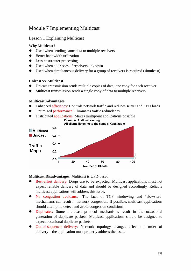
139
Module 7 Implementing Multicast
Lesson 1 Explaining Multicast
Why Multicast? � Used when sending same data to multiple receivers � Better bandwidth utilization � Less host/router processing � Used when addresses of receivers unknown � Used when simultaneous delivery for a group of receivers is required (simulcast) Unicast vs. Multicast � Unicast transmission sends multiple copies of data, one copy for each receiver. � Multicast transmission sends a single copy of data to multiple receivers. Multicast Advantages � Enhanced efficiency: Controls network traffic and reduces server and CPU loads � Optimized performance: Eliminates traffic redundancy � Distributed applications: Makes multipoint applications possible
Multicast Disadvantages: Multicast is UPD-based � Best-effort delivery: Drops are to be expected. Multicast applications must not
expect reliable delivery of data and should be designed accordingly. Reliable multicast applications will address this issue.
� No congestion avoidance: The lack of TCP windowing and “slowstart” mechanisms can result in network congestion. If possible, multicast applications should attempt to detect and avoid congestion conditions.
� Duplicates: Some multicast protocol mechanisms result in the occasional generation of duplicate packets. Multicast applications should be designed to expect occasional duplicate packets.
� Out-of-sequence delivery: Network topology changes affect the order of delivery—the application must properly address the issue.

140
Types of Multicast Applications � One to many: A single host sending to two or more (n) receivers � Many to many: Any number of hosts sending to the same multicast group; hosts
are also members of the group (sender = receiver) � Many to one: Any number of receivers sending data back to a source (via unicast
or multicast) IP Multicast Basic Addressing � IP group addresses:
- Class D address (high-order three bits are set) - Range from 224.0.0.0 through 239.255.255.255 � Well-known addresses assigned by IANA: Reserved use: 224.0.0.0 through
224.0.0.255 - 224.0.0.1 (all multicast systems on subnet) - 224.0.0.2 (all routers on subnet) - 224.0.0.4 (all DVMRP (Distance Vector Multicast Routing Protocol) routers) - 224.0.0.13 (all PIMv2 routers) - 224.0.0.5, 224.0.0.6, 224.0.0.9, and 224.0.0.10 used by unicast routing protocols
- 224.0.0.5 (all OSPF routers) - 224.0.0.6 (all OSPF designated routers (DRs)) - 224.0.0.9 (all RIPv2 routers) - 224.0.0.10 (all EIGRP routers)
� Transient addresses, assigned and reclaimed dynamically (within applications): - Global range: 224.0.1.0-238.255.255.255
- 224.2.X.X usually used in MBONE applications - Limited (local) scope: 239.0.0.0/8 for private IP multicast addresses (RFC-2365)
- Site-local scope: 239.255.0.0/16 - Organization-local scope: 239.192.0.0 to 239.251.255.255
� Part of a global scope recently used for new protocols and temporary usage Layer 2 Multicast Addressing � 01-00-5e: reserved � 5 bits overlap, so several Layer 3 addresses may map to the same Layer 2
multicast address.

141
Learning About Multicast Sessions � Potential receivers have to learn about multicast streams or sessions available
before multicast application is launched. Possibilities: - Another multicast application sending to a well-known group whose members are all potential receivers - Directory services - Web page, e-mail - Session Announcement Protocol

142
Lesson 2 IGMP and Layer 2 Issues
IGMPv2 � Group-specific query
- Router sends group-specific query to make sure that there are no members present before ceasing to forward data for the group for that subnet. � Leave group message
- Host sends leave message if it leaves the group and is the last member (reduces leave latency in comparison to v1).
IGMPv2—Joining a Group � Members joining a multicast group do not have to wait for a query to join. They
send an unsolicited report indicating their interest. This procedure reduces join latency for the end system joining if no other members are present.
� When there are two IGMP routers on the same Ethernet segment (broadcast domain), the router with the highest IP address is the designated querier.
IGMPv2—Leaving a Group 1. H2 sends a leave message. 2. Router sends group-specific query. 3. A remaining member host sends report, so group remains active.

143
IGMPv3—Joining a Group � Joining member sends IGMPv3 report to 224.0.0.22 immediately upon joining.

144
IGMPv3—Maintaining State � Router sends periodic queries: All IGMPv3 members respond.
- Reports contain multiple group state records. Determining IGMP Version Running Layer 2 Multicast Frame Switching � Problem: Layer 2 flooding of multicast frames
- Typical Layer 2 switches treat multicast traffic as unknown or broadcast and must flood the frame to every port (in VLAN). - Static entries may sometimes be set to specify which ports must receive which groups of multicast traffic. - Dynamic configuration of these entries may reduce administration.
rtr-a> show ip igmp interface e0
Ethernet0 is up, line protocol is up
Internet address is 1.1.1.1, subnet mask is 255.2 55.255.0
IGMP is enabled on interface
Current IGMP version is 2
CGMP is disabled on interface
IGMP query interval is 60 seconds
IGMP querier timeout is 120 seconds
IGMP max query response time is 10 seconds
Inbound IGMP access group is not set
Multicast routing is enabled on interface
Multicast TTL threshold is 0
Multicast designated router (DR) is 1.1.1.1 (this system)
IGMP querying router is 1.1.1.1 (this system)
Multicast groups joined: 224.0.1.40 224.2.127.254

145
Layer 2 Multicast Switching Solutions � Cisco Group Management Protocol (CGMP): Simple, proprietary; routers and
switches � IGMP snooping: Complex, standardized, proprietary implementations; switches
only Layer 2 Multicast Frame Switching CGMP � Runs on switches and routers. � CGMP packets sent by routers to switches at the CGMP
multicast MAC address - 0100.0cdd.dddd � CGMP packet contains:
- Type field: join or leave - MAC address of the IGMP client - Multicast MAC address of the group � Switch uses CGMP packet information to add or remove an
entry for a particular multicast MAC address. Layer 2 Multicast Frame Switching IGMP Snooping � Switches become IGMPaware. � IGMP packets are intercepted by the CPU or by special
hardware ASICs. � The switch must examine contents of IGMP messages to
determine which ports want what traffic: - IGMP membership reports - IGMP leave messages � Effect on switch:
- Must process all Layer 2 multicast packets - Administration load increased with multicast traffic load - Requires special hardware to maintain throughput

146
Lesson 3 Explaining Multicast Routing Protocols
Multicast Protocol Basics � Types of multicast distribution trees
- Source-rooted; also called shortest path trees (SPTs) - Rooted at a meeting point in the network; shared trees
- Rendezvous point (RP) - Core
� Types of multicast protocols - Dense mode protocols: flood multicast traffic to all parts of the network and prune the flows where there are no receivers using a periodic flood-and-prune mechanism. - Sparse mode protocols: use an explicit join mechanism where distribution trees are built on demand by explicit tree join messages sent by routers that have directly connected receivers.
Shortest-Path Trees

147
Shared Distribution Trees Multicast Distribution Trees Identification � (S,G) entries
- For this particular source sending to this particular group - Traffic forwarded via the shortest path from the source � (*,G) entries
- For any (*) source sending to this group - Traffic forwarded via a meeting point for this group
Multicast Forwarding � Multicast routing operation is the opposite of unicast routing.
- Unicast routing is concerned with where the packet is going. - Multicast routing is concerned with where the packet comes from. � Multicast routing uses Reverse Path Forwarding to prevent forwarding loops. PIM-DM (PIM Dense Mode) Flood and Prune

148
� PIM dense mode (PIM-DM) initially floods multicast traffic to all parts of the network. PIMDM initially floods traffic out of all non-RPF interfaces where there is another PIM-DM neighbor or a directly connected member of the group.
� PIM-DM prune messages are sent (denoted by dashed arrows) to stop the
unwanted traffic. PIM-SM (PIM Sparse Mode) � Protocol independent: works with any of the underlying unicast routing protocols � Supports both source and shared trees � Based on an explicit pull model: traffic is forwarded only to the parts of the
network that need it. � Uses an RP - Senders and receivers “meet each other.”
- Senders are registered with RP by their first-hop router. - Receivers are joined to the shared tree (rooted at the RP) by their local DR.

149
PIM-SM Shared Tree Join Multiple RPs with Auto RP

150
Lesson 3 Multicast Configuration and Verification
PIM-SM Configuration Commands � R(config)#ip multicast-routing
- Enables multicast routing. � R(config-if)#ip pim { sparse-mode | sparse-dense-mode}
- Enables PIM SM on an interface; the sparse-dense-mode option enables mixed sparse-dense groups. � R(config)#ip pim send-rp-announce { interface type} scope
{ ttl} group-list { acl} R(config)#ip pim send-rp-discovery { interface type} scope { ttl}
- Configures the ability of a group of routers to be and discover RPs dynamically. Inspecting Multicast Routing Table � R#show ip mroute [ group-address] [summary] [count] [active
kbps]
- Displays the contents of the IP multicast routing table - summary : Displays a one-line, abbreviated summary of each entry in the IP multicast routing table. - count : Displays statistics about the group and source, including number of packets, packets per second, average packet size, and bits per second. - active : Displays the rate at which active sources are sending to multicast groups. Active sources are those sending at a rate specified in the kbps argument or higher. The kbps argument defaults to 4 kbps.
show ip mroute
NA-1# sh ip mroute
IP Multicast Routing Table
Flags: D - Dense, S - Sparse, B - Bidir Group, s - SSM Group, C - Connected
L - Local, P - Pruned, R - RP-bit set, F - R egister flag,
T - SPT-bit set, J - Join SPT, M - MSDP crea ted entry,
X - Proxy Join Timer Running, A - Advertised via MSDP, U - URD,
I - Received Source Specific Host Report
Outgoing interface flags: H - Hardware switched
Timers: Uptime/Expires
Interface state: Interface, Next-Hop or VCD, State/ Mode
(*, 224.1.1.1), 00:07:54/00:02:59, RP 10.127.0.7, f lags: S
Incoming interface: Null, RPF nbr 0.0.0.0
Outgoing interface list:
Serial1/3, Forward/Sparse, 00:07:54/00:02:32
(172.16.8.1, 224.1.1.1), 00:01:29/00:02:08, flags: TA
Incoming interface: Serial1/4, RPF nbr 10.139.16. 130
Outgoing interface list:
Serial1/3, Forward/Sparse, 00:00:57/00:02:02

151
� (*, G) entry: Timers, the RP address for the group, and the flags for the group (S is “sparse”) are listed. - The incoming interface is the interface toward the RP—if it is “Null,” the router itself is the RP. The Reverse Path Forwarding (RPF) neighbor is the next-hop address toward the RP—if it is “0.0.0.0,” the router is the RP for the group. - The outgoing interface list (OIL) is a list of outgoing interfaces, along with modes and timers. � (S, G) entry: Timers and flags for the entry are listed (“T” indicates that it is on
the SPT; “A” indicates that it is to be advertised by Multicast Source Discovery Protocol [MSDP]). - The incoming interface is the interface toward the source S. The RPF neighbor is the next-hop address toward the source—if it is “0.0.0.0,” the source is directly attached. - The OIL is a list of outgoing interfaces, in addition to modes and timers.
Finding PIM Neighbors � R#show ip pim interface [ type number] [count]
- Displays information about interfaces configured for PIM � R#show ip pim neighbor [ type number]
- Lists the PIM neighbors discovered by the Cisco IOS software � R#mrinfo [ hosthanme | address]
- Queries which neighboring multicast routers are peering with the local router or router specified
show ip pim interface show ip pim neighbor
NA-2# show ip pim interface
Address Interface Ver/ Nbr Q uery DR DR
Mode Count Intvl Prior
10.139.16.133 Serial0/0 v2/S 1 3 0 1 0.0.0.0
10.127.0.170 Serial1/2 v2/S 1 3 0 1 0.0.0.0
10.127.0.242 Serial1/3 v2/S 1 3 0 1 0.0.0.0
NA-2# show ip pim neighbor
PIM Neighbor Table
Neighbor Interface Uptime/Expires Ver DR
Address Priority
10.139.16.134 Serial0/0 00:01:46/00:01 :28 v2 None
10.127.0.169 Serial1/2 00:01:05/00:01 :40 v2 1 (BD)
10.127.0.241 Serial1/3 00:01:56/00:01 :18 v2 1 (BD)

152
Checking RP Information � R(config)#show ip pim rp [ group-name | group-address |
mapping]
- Displays active RPs that are cached with associated multicast routing entries - mapping - displays all group-to-RP mappings that the router is aware of
� R(config)#show ip rpf { address | name}
- Displays how IP multicast routing does Reverse Path Forwarding (RPF) - address - IP address of a source of an RP
show ip pim rp show ip rpf
P4-2# show ip pim rp
Group: 224.1.2.3, RP: 10.127.0.7, uptime 00:00:20, expires never
P4-2# show ip pim rp mapping
PIM Group-to-RP Mappings
Group(s) 224.0.1.39/32
RP 10.127.0.7 (NA-1), v1
Info source: local, via Auto-RP
Uptime: 00:00:21, expires: never
Group(s) 224.0.1.40/32
RP 10.127.0.7 (NA-1), v1
Info source: local, via Auto-RP
Uptime: 00:00:21, expires: never
Group(s): 224.0.0.0/4, Static
RP: 10.127.0.7 (NA-1)
(towards the RP)
NA-2# show ip rpf 10.127.0.7
RPF information for NA-1 (10.127.0.7)
RPF interface: Serial1/3
RPF neighbor: ? (10.127.0.241)
RPF route/mask: 10.127.0.7/32
RPF type: unicast (ospf 1)
RPF recursion count: 0
Doing distance-preferred lookups across tables
(towards the source)
NA-2# show ip rpf 10.139.17.126
RPF information for ? (10.139.17.126)
RPF interface: Serial0/0
RPF neighbor: ? (10.139.16.134)
RPF route/mask: 10.139.17.0/25
RPF type: unicast (ospf 1)
RPF recursion count: 0
Doing distance-preferred lookups across tables

153
Checking the Group State � R#show ip igmp interface [ type number]
- Displays multicast-related information about an interface � R#show ip igmp groups [ group-address | type number]
- Displays the multicast groups that are directly connected to the router and that were learned via IGMP � ip igmp join-group group-address:
- Joins a multicast group � ip igmp static-group group-address:
- Configures the router as a statically connected member of a group show ip igmp interface show ip igmp groups Verifying IGMP Snooping � Switch>show multicast group [igmp] [ mac_addr] [ vlan_id]
- Displays information about multicast groups. - If igmp keyword is used, only IGMP-learned information is shown. � Switch>show multicast router [igmp] [ mod_num/port_num]
[ vlan_id]
- Displays information on dynamically learned and manually configured multicast router ports.
rtr-a> show ip igmp interface e0
Ethernet0 is up, line protocol is up
Internet address is 1.1.1.1, subnet mask is 255.2 55.255.0
IGMP is enabled on interface
Current IGMP version is 2
CGMP is disabled on interface
IGMP query interval is 60 seconds
IGMP querier timeout is 120 seconds
IGMP max query response time is 10 seconds
Inbound IGMP access group is not set
Multicast routing is enabled on interface
Multicast TTL threshold is 0
Multicast designated router (DR) is 1.1.1.1 (this system)
IGMP querying router is 1.1.1.1 (this system)
Multicast groups joined: 224.0.1.40 224.2.127.254
rtr-a> sh ip igmp groups
IGMP Connected Group Membership
Group Address Interface Uptime Expires Last Reporter
224.1.1.1 Ethernet0 6d17h 00:01:47 1.1.1.12
224.0.1.40 Ethernet0 6d17h never 1.1.1.17

154
- If igmp keyword is used, only IGMP-learned information is shown. Verifying IGMP Snooping—Example
Switch> show igmp statistics 10
IGMP enabled
IGMP statistics for vlan 10:
IGMP statistics for vlan 10:
Transmit:
General Queries: 0
Group Specific Queries: 0
Reports: 0
Leaves: 0
Receive:
General Queries: 1
Group Specific Queries: 0
Reports: 2
Leaves: 0
Total Valid pkts: 4
Total Invalid pkts: 0
Other pkts: 1
MAC-Based General Queries: 0
Failures to add GDA to EARL: 0
Topology Notifications: 0

155
Switch> show multicast router igmp
Port Vlan
---------- ----------------
4/1 10
Total Number of Entries = 1
'*' - Configured
'+' - RGMP-capable
Switch> show multicast group igmp
VLAN Dest MAC/Route Des [CoS] Destination Ports or VCs / [Protocol Type]
---- --------------------------------------------- ------------------------
10 01-00-5e-00-01-28 4/1
10 01-00-5e-01-02-03 4/1-2
Total Number of Entries = 2

156
Module 8 Implementing IPv6
Lesson 1 Introducing IPv6
� IPv6 can recreate end-to-end communications without the need for Network Address Translation (NAT)
IPv6 Advanced Features � Larger address space
- Global reachability and flexibility - Aggregation - Multihoming - Autoconfiguration - Plug-and-play - End to end without NAT - Renumbering � Simpler header
- Routing efficiency - Performance and forwarding rate scalability - No broadcasts - No checksums - Extension headers - Flow labels � Mobility and security
- Mobile IP RFC-compliant - IPsec mandatory (or native) for IPv6 � Transition richness
- Dual stack - 6to4 tunnels - Translation
Larger Address Space � IPv4: 32 bits or 4 bytes long � IPv6: 128 bits or 16 bytes long Larger Address Space Enables Address Aggregation

157
� Aggregation of prefixes announced in the global routing table � Efficient and scalable routing � Improved bandwidth and functionality for user traffic

158
Lesson 2 Defining IPv6 Addressing
Simple and Efficient Header � 64-bit aligned fields and fewer fields � Hardware-based, efficient processing � Improved routing efficiency and performance � Faster forwarding rate with better scalability IPv4 and IPv6 Header Comparison � Version: A 4-bit field. It contains the number 6 instead of the number 4 for IPv4. � Traffic Class: An 8-bit field similar to the type of service (ToS) field in IPv4. It
tags the packet with a traffic class that it uses in differentiated services (DiffServ). These functionalities are the same for IPv6 and IPv4.
� Flow Label: A completely new 20-bit field. It tags a flow for the IP packets. It can be used for multilayer switching techniques and faster packet-switching performance.
� Payload Length: Similar to the Total Length field of IPv4. � Next Header: The value of this field determines the type of information that
follows the basic IPv6 header. It can be a transport-layer packet, such as TCP or UDP, or it can be an extension header. The next header field is similar to the

159
Protocol field of IPv4. � Hop Limit: This field specifies the maximum number of hops that an IP packet
can traverse. Each hop or router decreases this field by one (similar to the Time to Live [TTL] field in IPv4). Because there is no checksum in the IPv6 header, the router can decrease the field without recomputing the checksum. On IPv4 routers the recomputation costs processing time.
� Source Address: This field has 16 octets or 128 bits. It identifies the source of the packet.
� Destination Address: This field has 16 octets or 128 bits. It identifies the destination of the packet.
� Extension Headers: The extension headers, if any, and the data portion of the packet follow the eight fields. The number of extension headers is not fixed, so the total length of the extension header chain is variable.
IPv6 Extension Headers � IPv6 header: This header is the basic header described in the previous figure. � Hop-by-hop options header: When this header is used for the router alert
(Resource Reservation Protocol [RSVP] and Multicast Listener Discovery version 1 [MLDv1]) and the jumbogram, this header (value = 0) is processed by all hops in the path of a packet. When present, the hop-by-hop options header always follows immediately after the basic IPv6 packet header.
� Destination options header (when the routing header is used): This header (value = 60) can follow any hop-by-hop options header, in which case the destination options header is processed at the final destination and also at each visited address specified by a routing header. Alternatively, the destination options header can follow any Encapsulating Security Payload (ESP) header, in which case the destination options header is processed only at the final destination. For example, mobile IP uses this header.
� Routing header: This header (value = 43) is used for source routing and mobile IPv6.
� Fragment header: This header is used when a source must fragment a packet that is larger than the MTU for the path between itself and a destination device. The fragment header is used in each fragmented packet.
� Authentication header and Encapsulating Security Payload header: The authentication header (value = 51) and the ESP header (value = 50) are used within IPsec to provide authentication, integrity, and confidentiality of a packet. These headers are identical for both IPv4 and IPv6.
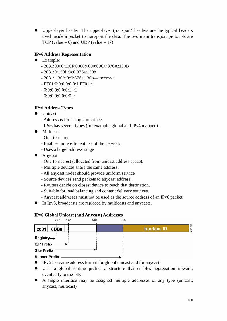
160
� Upper-layer header: The upper-layer (transport) headers are the typical headers used inside a packet to transport the data. The two main transport protocols are TCP (value = 6) and UDP (value = 17).
IPv6 Address Representation � Example:
- 2031:0000:130F:0000:0000:09C0:876A:130B - 2031:0:130f::9c0:876a:130b - 2031::130f::9c0:876a:130b—incorrect - FF01:0:0:0:0:0:0:1 FF01::1 - 0:0:0:0:0:0:0:1 ::1 - 0:0:0:0:0:0:0:0 ::
IPv6 Address Types � Unicast
- Address is for a single interface. - IPv6 has several types (for example, global and IPv4 mapped). � Multicast
- One-to-many - Enables more efficient use of the network - Uses a larger address range � Anycast
- One-to-nearest (allocated from unicast address space). - Multiple devices share the same address. - All anycast nodes should provide uniform service. - Source devices send packets to anycast address. - Routers decide on closest device to reach that destination. - Suitable for load balancing and content delivery services. - Anycast addresses must not be used as the source address of an IPv6 packet. � In Ipv6, broadcasts are replaced by multicasts and anycasts. IPv6 Global Unicast (and Anycast) Addresses � IPv6 has same address format for global unicast and for anycast. � Uses a global routing prefix—a structure that enables aggregation upward,
eventually to the ISP. � A single interface may be assigned multiple addresses of any type (unicast,
anycast, multicast).

161
� Every IPv6-enabled interface must contain at least one loopback (::1/128) and one link-local address.
� Optionally, every interface can have multiple unique local and global addresses. � Anycast address is a global unicast address assigned to a set of interfaces
(typically on different nodes). � IPv6 anycast is used for a network multihomed to several ISPs that have multiple
connections to each other. IPv6 Unicast Addressing � Unicast: One to one
- Global - Link local (FE80::/10) � A single interface may be assigned multiple IPv6 addresses of any type: unicast,
anycast, or multicast.

162
Lesson 3 Implementing Dynamic IPv6 Addresses
Aggregatable Global Unicast Addresses � Cisco uses the extended universal identifier (EUI)-64 format to do stateless
autoconfiguration. � This format expands the 48-bit MAC address to 64 bits by inserting “FFFE” into
the middle 16 bits. � To make sure that the chosen address is from a unique Ethernet MAC address, the
universal/local (U/L bit) is set to 1 for global scope (0 for local scope). Link-Local Address � Link-local addresses have a scope limited to the link and are dynamically created
on all IPv6 interfaces by using a specific link-local prefix FE80::/10 and a 64-bit interface identifier.
� Link-local addresses are used for automatic address configuration, neighbor discovery, and router discovery. Link-local addresses are also used by many routing protocols.
� Link-local addresses can serve as a way to connect devices on the same local network without needing global addresses.
� When communicating with a link-local address, you must specify the outgoing interface because every interface is connected to FE80::/10.
EUI-64 to IPv6 Interface Identifier � A modified EUI-64 address is formed by inserting “FFFE” and “complementing”
a bit identifying the uniqueness of the MAC address.
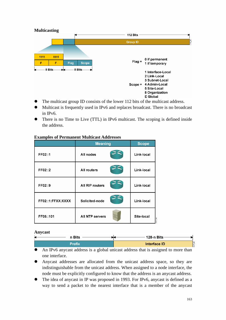
163
Multicasting � The multicast group ID consists of the lower 112 bits of the multicast address. � Multicast is frequently used in IPv6 and replaces broadcast. There is no broadcast
in IPv6. � There is no Time to Live (TTL) in IPv6 multicast. The scoping is defined inside
the address. Examples of Permanent Multicast Addresses Anycast � An IPv6 anycast address is a global unicast address that is assigned to more than
one interface. � Anycast addresses are allocated from the unicast address space, so they are
indistinguishable from the unicast address. When assigned to a node interface, the node must be explicitly configured to know that the address is an anycast address.
� The idea of anycast in IP was proposed in 1993. For IPv6, anycast is defined as a way to send a packet to the nearest interface that is a member of the anycast

164
group, which enables a type of discovery mechanism to the nearest point. � There is little experience with widespread anycast usage. A few anycast addresses
are currently assigned: the router-subnet anycast and the Mobile IPv6 home agent anycast.
� An anycast address must not be used as the source address of an IPv6 packet. Stateless Autoconfiguration A Standard Stateless Autoconfiguration
� Stage 1: The PC sends a router
solicitation to request a prefix for stateless autoconfiguration.
� Stage 2: The router replies with a
router advertisement.

165
IPv6 Mobility � IPv6 mobility is different from IPv4 mobility in several ways:
- The IPv6 address space enables Mobile IP deployment in any kind of large environment. - Because of the vast IPv6 address space, foreign agents are no longer required. Infrastructures do not need an upgrade to accept Mobile IPv6 nodes, so the care-of address (CoA) can be a global IPv6 routable address for all mobile nodes. - The Mobile IPv6 model takes advantage of some of the benefits of the IPv6 protocol itself. Examples include option headers, neighbor discovery, and autoconfiguration. - In many cases, triangle routing is eliminated, because Mobile IPv6 route optimization allows mobile nodes and corresponding nodes to communicate directly. Support for route optimization is a fundamental part of the protocol, rather than a nonstandard set of extensions. Support is also integrated into Mobile IPv6 for allowing route optimization to coexist efficiently with routers that perform ingress filtering. Mobile IPv6 route optimization can operate securely even without prearranged security associations. It is expected that route optimization can be deployed on a global scale between all mobile nodes and correspondent nodes. - Mobile nodes work transparently even with other nodes that do not support mobility (same as in IPv4 mobility). - The dynamic home agent address-discovery mechanism in Mobile IPv6 returns a single reply to the mobile node. The directed broadcast approach used in IPv4 returns separate replies from each home agent. - Most packets sent to a mobile node while it is away from home in Mobile IPv6 are sent using an IPv6 routing header rather than IP encapsulation, reducing the amount of resulting overhead compared to Mobile IPv4.

166
Lesson 4 Using IPv6 with OSPF and Other Routing Protocols
IPv6 Routing Protocols � IPv6 routing types
- Static - RIPng (RFC 2080) - OSPFv3 (RFC 2740) - IS-IS for IPv6 - MP-BGP4 (RFC 2545/2858) - EIGRP for IPv6 � The ipv6 unicast-routing command is required to enable IPv6 before any
routing protocol configured. RIPng � Same as IPv4
- Distance vector, radius of 15 hops, split horizon, and poison reverse - Based on RIPv2 � Updated features for IPv6
- IPv6 prefix, next-hop IPv6 address - Uses the multicast group FF02::9, the all-rip-routers multicast group, as the destination address for RIP updates - Uses IPv6 for transport - Named RIPng
OSPF Version 3 (OSPFv3) (RFC 2740) � Similar to IPv4
- Same mechanisms, but a major rewrite of the internals of the protocol � Updated features for IPv6
- Every IPv4-specific semantic removed - Carry IPv6 addresses - Link-local addresses used as source - IPv6 transport - OSPF for IPv6 currently an IETF proposed standard
Integrated IS-IS � Same as for IPv4 � Extensions for IPv6:
- Two new Type, Length, Value (TLV) attributes: - IPv6 reachability (with 128-bit prefix) - IPv6 interface address (with 128 bits)
- New protocol identifier - Not yet an IETF standard

167
Multiprotocol Border Gateway Protocol (MP-BGP) (RFC 2858) � Multiprotocol extensions for BGP4:
- Enables protocols other than IPv4 - New identifier for the address family � IPv6 specific extensions:
- Scoped addresses: NEXT_HOP contains a global IPv6 address and potentially a link-local address (only when there is a link-local reachability with the peer). - NEXT_HOP and Network Layer Reachability Information (NLRI) are expressed as IPv6 addresses and prefix in the multiprotocol attributes.
OSPFv3—Hierarchical Structure � Topology of an area is invisible from outside of the area:
- LSA flooding is bounded by area. - SPF calculation is performed separately for each area. � Backbones must be contiguous. � All areas must have a connection to the backbone:
- Otherwise a virtual link must be used to connect to the backbone. OSPFv3—Similarities with OSPFv2 � OSPFv3 is OSPF for IPv6 (RFC 2740)
- Based on OSPFv2, with enhancements - Distributes IPv6 prefixes - Runs directly over IPv6 � OSPFv3 and OSPFv2 can be run concurrently, because each address family has a
separate SPF (ships in the night). � OSPFv3 uses the same basic packet types as OSPFv2:
- Hello - Database description (DBD) - Link state request (LSR) - Link state update (LSU) - Link state acknowledgment (ACK) � Neighbor discovery and adjacency formation mechanism are identical. � RFC-compliant NBMA and point-to-multipoint topology modes are supported.
Also supports other modes from Cisco, such as point-to-point and broadcast, including the interface.
� LSA flooding and aging mechanisms are identical. Enhanced Routing Protocol Support Differences from OSPFv2 � OSPFv3 has the same five
packet types, but some fields have been changed.

168
� All OSPFv3 packets have a 16-byte header vs. the 24-byte header in OSPFv2. OSPFv3 Differences from OSPFv2 � OSPFv3 protocol processing is per link, not per subnet
- IPv6 connects interfaces to links. - Multiple IPv6 subnets can be assigned to a single link. - Two nodes can talk directly over a single link, even though they do not share a common subnet. - The terms “network” and “subnet” are being replaced with “link.” - An OSPF interface now connects to a link instead of to a subnet. � Multiple OSPFv3 protocol instances can now run over a single link
- This structure allows separate autonomous systems, each running OSPF, to use a common link. A single link could belong to multiple areas. - Instance ID is a new field that is used to allow multiple OSPFv3 protocol instances per link. - In order to have two instances talk to each other, they need to have the same instance ID. By default, it is 0, and for any additional instance it is increased. � Multicast addresses:
- FF02::5—Represents all SPF routers on the link-local scope; equivalent to 224.0.0.5 in OSPFv2 - FF02::6—Represents all DR routers on the link-local scope; equivalent to 224.0.0.6 in OSPFv2 � Removal of address semantics
- IPv6 addresses are no longer present in OSPF packet header (part of payload information). - Router LSA and network LSA do not carry IPv6 addresses. - Router ID, area ID, and link-state ID remain at 32 bits. - DR and BDR are now identified by their router ID and not by their IP address. � Security
- OSPFv3 uses IPv6 AH and ESP extension headers instead of variety of the mechanisms defined in OSPFv2.

169
LSA Overview
� OSPFv3 LSA features include the following: - The LSA is composed of a router ID, area ID, and link-state ID. They are each 32 bits and are not derived from an IPv4 address. - Router LSAs and network LSAs contain only 32-bit IDs. They do not contain addresses. - LSAs have flooding scopes that define a diameter that they should be flooded to:
- Link local: Flood all routers on the link. - Area: Flood all routers within an OSPF area. - Autonomous system (AS): Flood all routers within the entire OSPF AS.
- OSPFv3 supports the forwarding of unknown LSAs based on the flooding scope. This can be useful in an NSSA. - OSPFv3 now takes advantage of IPv6 multicasting, using FF02::5 for all OSPF routers and FF02::6 for the OSPF DR and the OSPF BDR. � The two renamed LSAs are as follows:
- Interarea prefix LSAs for area border routers (ABRs) (type 3): Type 3 LSAs advertise internal networks to routers in other areas (interarea routes). Type 3 LSAs may represent a single network or a set of networks summarized into one advertisement. Only ABRs generate summary LSAs. In OSPF for IPv6, addresses for these LSAs are expressed as prefix, prefix length instead of address, mask. The default route is expressed as a prefix with length 0. - Interarea router LSAs for autonomous system boundary routers (ASBRs) (type 4): Type 4 LSAs advertise the location of an ASBR. Routers that are trying to reach an external network use these advertisements to determine the best path to the next hop. ASBRs generate type 4 LSAs. � The two new LSAs in IPv6 are as follows:
- Link LSAs (type 8): Type 8 LSAs have link-local flooding scope and are never flooded beyond the link with which they are associated. Link LSAs provide the link-local address of the router to all other routers attached to the link, inform other routers attached to the link of a list of IPv6 prefixes to associate with the link, and allow the router to assert a collection of options bits to associate with the

170
network LSA that will be originated for the link. - Intra-area prefix LSAs (type 9): A router can originate multiple intra-area prefix LSAs for each router or transit network, each with a unique link-state ID. The link-state ID for each intra-area prefix LSA describes its association to either the router LSA or the network LSA. The link-state ID also contains prefixes for stub and transit networks.
Larger Address Space Enables Address Aggregation � Aggregation of prefixes announced in the global routing table � Efficient and scalable routing � Improved bandwidth and functionality for user traffic Configuring OSPFv3 in Cisco IOS Software � Similar to OSPFv2
- Prefixes existing interface and EXEC mode commands with “ipv6” � Interfaces configured directly
- Replaces network command � “Native” IPv6 router mode
- Not a submode of router ospf command � To configure OSPFv3, first enable IPv6, and then enable OSPFv3 and specify a
router ID, using the following commands: - R(config)#ipv6 unicast-routing - R(config)#ipv6 router ospf process-id - R(config-rtr)#router-id router-id

171
Enabling OSPFv3 Globally
Enabling OSPFv3 on an Interface
ipv6 unicast-routing
!
ipv6 router ospf 1
router-id 2.2.2.2
interface Ethernet0/0
ipv6 address 3FFE:FFFF:1::1/64
ipv6 ospf 1 area 0
ipv6 ospf priority 20
ipv6 ospf cost 20

172
Cisco IOS OSPFv3-Specific Attributes � Configuring area range:
- area area-id range ipv6_prefix/prefix_length [advertise | notadvertise] [cost cost] � Showing new LSAs:
- show ipv6 ospf [ process-id] database link - show ipv6 ospf [ process-id] database prefix � Example:
- Router(config)#ipv6 router ospf 1 - Router(config-rtr)#area range 1 2001:0DB8::/48
- The cost of the summarized routes will be the highest cost of the routes being summarized. For example, if the following routes are summarized:
OI 2001:0DB8:0:0:7::/64 [110/20] via FE80::A8BB:CCFF:FE00:6F00, Ethernet0/0 OI 2001:0DB8:0:0:8::/64 [110/100] via FE80::A8BB:CCFF:FE00:6F00, Ethernet0/0 OI 2001:0DB8:0:0:9::/64 [110/20] via FE80::A8BB:CCFF:FE00:6F00, Ethernet0/0
- They become one summarized route: OI 2001:0DB8::/48 [110/100] via FE80::A8BB:CCFF:FE00:6F00, Ethernet0/0
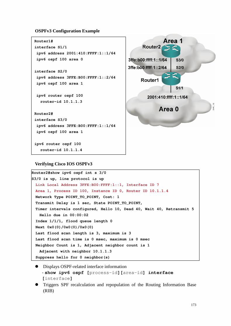
173
OSPFv3 Configuration Example Verifying Cisco IOS OSPFv3 � Displays OSPF-related interface information
- show ipv6 ospf [ process-id][ area-id] interface [ interface]
� Triggers SPF recalculation and repopulation of the Routing Information Base (RIB)
Router1#
interface S1/1
ipv6 address 2001:410:FFFF:1::1/64
ipv6 ospf 100 area 0
interface S2/0
ipv6 address 3FFE:B00:FFFF:1::2/64
ipv6 ospf 100 area 1
ipv6 router ospf 100
router-id 10.1.1.3
Router2#
interface S3/0
ipv6 address 3FFE:B00:FFFF:1::1/64
ipv6 ospf 100 area 1
ipv6 router ospf 100
router-id 10.1.1.4
Router2#show ipv6 ospf int s 3/0
S3/0 is up, line protocol is up
Link Local Address 3FFE:B00:FFFF:1::1, Interface ID 7
Area 1, Process ID 100, Instance ID 0, Router ID 10 .1.1.4
Network Type POINT_TO_POINT, Cost: 1
Transmit Delay is 1 sec, State POINT_TO_POINT,
Timer intervals configured, Hello 10, Dead 40, Wa it 40, Retransmit 5
Hello due in 00:00:02
Index 1/1/1, flood queue length 0
Next 0x0(0)/0x0(0)/0x0(0)
Last flood scan length is 3, maximum is 3
Last flood scan time is 0 msec, maximum is 0 msec
Neighbor Count is 1, Adjacent neighbor count is 1
Adjacent with neighbor 10.1.1.3
Suppress hello for 0 neighbor(s)

174
- clear ipv6 ospf [ process-id] {process | force-spf | redistribution | counters [neighbor [ neighbor-interface | neighbor-id]]}
show ipv6 ospf
R7#show ipv6 ospf
Routing Process “ospfv3 1” with ID 75.0.7.1
It is an area border and autonomous system boundary router
Redistributing External Routes from, connected
SPF schedule delay 5 secs, Hold time between two SP Fs 10 secs
Minimum LSA interval 5 secs. Minimum LSA arrival 1 secs
LSA group pacing timer 240 secs
Interface floor pacing timer 33 msecs
Retransmission pacing timer 33 msecs
Number of external LSA 3. Checksum Sum 0x12B75
Number of areas in this router is 2. 1 normal 0 stu b 1 nssa
Area BACKBONE(0)
Number of interfaces in this area is 1
SPF algorithm executed 23 times
Number of LSA 14. Checksum Sum 0x760AA
Number of DCbitless LSA 0
Number of Indication LSA 0
Number of DoNotAge LSA 0
Flood list length 0
Area 2
Number of interfaces in this area is 1
It is a NSSA area
Perform type-7/type-5 LSA translation
SPF algorithm executed 17 times
Number of LSA 25. Checksum Sum 0xE3BF0
Number of DCbitless LSA 0
Number of Indication LSA 0
Number of DoNotAge LSA 0
Flood list length 0

175
show ipv6 ospf neighbor detail
Router2#show ipv6 ospf neighbor detail
Neighbor 10.1.1.3
In the area 0 via interface S2/0
Neighbor: interface-id 14, link-local address 3 FFE:B00:FFFF:1::2
Neighbor priority is 1, State is FULL, 6 state changes
Options is 0x63AD1B0D
Dead timer due in 00:00:33
Neighbor is up for 00:48:56
Index 1/1/1, retransmission queue length 0, num ber of retransmission 1
First 0x0(0)/0x0(0)/0x0(0) Next 0x0(0)/0x0(0)/0 x0(0)
Last retransmission scan length is 1, maximum i s 1
Last retransmission scan time is 0 msec, maximu m is 0 msec

176
show ipv6 ospf database

177
show ipv6 ospf database database-summary

178
Lesson 4 Using IPv6 with IPv4
IPv4-to-IPv6 Transition � No fixed day to convert; no need to convert all at once. � Different transition mechanisms are available:
- Smooth integration of IPv4 and IPv6. - Use of dual stack or 6to4 tunnels. � Different compatibility mechanisms:
- IPv4 and IPv6 nodes can communicate. Cisco IOS Software Is IPV6-Ready: Cisco IOS Dual Stack � If both IPv4 and IPv6 are configured on an interface, this interface is
dual-stacked. Dual Stack

179
� Dual stack is an integration method where a node has implementation and connectivity to both an IPv4 and IPv6 network.
Cisco IOS Software Is IPv6-Ready: Overlay Tunnels � Tunneling encapsulates the IPv6 packet in the IPv4 packet. Tunneling � Tunneling is an integration method where an IPv6 packet is encapsulated within
another protocol, such as IPv4. This method of encapsulation is IPv4 protocol 41: - This method includes a 20-byte IPv4 header with no options and an IPv6 header and payload. - This method is considered dual stacking.
““““Isolated” Dual-Stack Host � Encapsulation can be done by edge routers between hosts or between a host and a
router.

180
Cisco IOS Software Is IPv6-Ready: Configured Tunnel � Configured tunnels require:
- Dual-stack endpoints - IPv4 and IPv6 addresses configured at each end
Example: Cisco IOS Tunnel Configuration Cisco IOS Software Is IPv6-Ready: 6to4 Tunneling � 6to4
- Is an automatic tunnel method - Gives a prefix to the attached IPv6 network
Translation—NAT-PT

181
� NAT-Protocol Translation (NAT-PT) is a translation mechanism that sits between an IPv6 network and an IPv4 network.
� The job of the translator is to translate IPv6 packets into IPv4 packets and vice versa.
� Other possible solutions are as follows: - ALGs: This method uses a dual-stack approach and enables a host in an IPv6-only domain to send data to another host in an IPv4-only domain. It requires that all application servers on a gateway run IPv6. - API: You can install a specific module in a host TCP/IP stack for every host on the network. The module intercepts IP traffic through an API and converts it for the IPv6 counterpart.