Embed Size (px)
Citation preview
C H A P T E R
Designing ATM Internetworks 8-1
8
Designing ATM Internetworks
This chapter describes current Asynchronous Transfer Mode (ATM) technologies that networkdesigners can use in their networks today. It also makes recommendations for designing non-ATMnetworks so that those networks can take advantage of ATM in the future without sacrificing currentinvestments in cable.
This chapter focuses on the following topics:
• ATM Overview
• Cisco’s ATM WAN Solutions
ATM DefinedATM is an evolving technology designed for the high-speed transfer of voice, video, and datathrough public and private networks in a cost-effective manner. ATM is based on the efforts of StudyGroup XVIII of the International Telecommunication Union Telecommunication StandardizationSector (ITU-T, formerly the Consultative Committee for International Telegraph and Telephone[CCITT]) and the American National Standards Institute (ANSI) to apply very large-scaleintegration (VLSI) technology to the transfer of data within public networks. Officially, the ATMlayer of the Broadband Integrated Services Digital Network (BISDN) model is defined byCCITT I.361.
Current efforts to bring ATM technology to private networks and to guarantee interoperabilitybetween private and public networks is being done by the ATM Forum, which was jointly foundedby Cisco Systems, NET/ADAPTIVE, Northern Telecom, and Sprint in 1991.
Role of ATM in InternetworksToday, ninety percent of computing power resides on desktops, and that power is growingexponentially. Distributed applications are increasingly bandwidth hungry, and the emergence of theInternet is driving most LAN architectures to the limit. Voice communications have increasedsignificantly with increasing reliance on centralized voice mail systems for verbal communications.The internetwork is the critical tool for information flow. Internetworks are being pressured to costless yet support the emerging applications and higher number of users with increased performance.
To date, local and wide area communications have remained logically separate. In the LAN,bandwidth is free and connectivity is limited only by hardware and implementation cost. The LANhas carried data only. In the WAN, bandwidth has been the overriding cost, and such delay-sensitivetraffic as voice has remained separate from data. New applications and the economics of supportingthem, however, are forcing these conventions to change.
8-2 Internetwork Design Guide
Role of ATM in Internetworks
The Internet is the first source of multimedia to the desktop and immediately breaks the rules. SuchInternet applications as voice and real-time video require better, more predictable LAN and WANperformance. In addition, the Internet also necessitates that the WAN recognize the traffic in theLAN stream, thereby driving LAN/WAN integration.
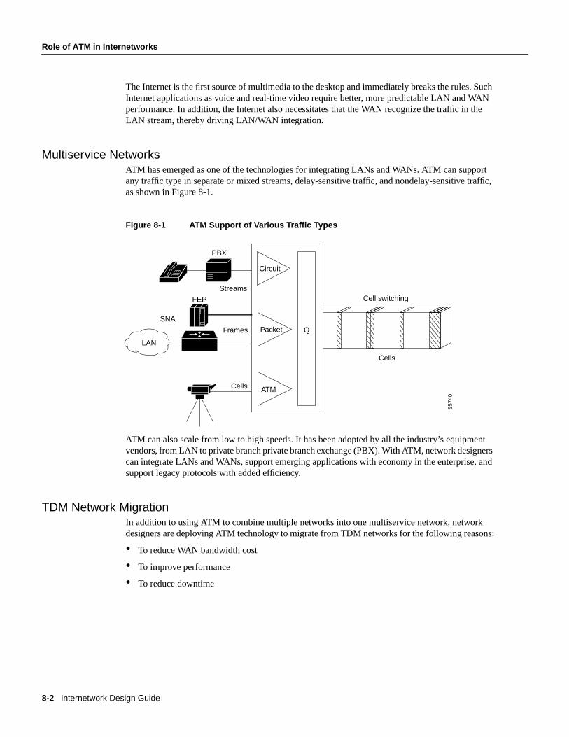
Multiservice NetworksATM has emerged as one of the technologies for integrating LANs and WANs. ATM can supportany traffic type in separate or mixed streams, delay-sensitive traffic, and nondelay-sensitive traffic,as shown in Figure 8-1.
Figure 8-1 ATM Support of Various Traffic Types
ATM can also scale from low to high speeds. It has been adopted by all the industry’s equipmentvendors, from LAN to private branch private branch exchange (PBX). With ATM, network designerscan integrate LANs and WANs, support emerging applications with economy in the enterprise, andsupport legacy protocols with added efficiency.
TDM Network MigrationIn addition to using ATM to combine multiple networks into one multiservice network, networkdesigners are deploying ATM technology to migrate from TDM networks for the following reasons:
• To reduce WAN bandwidth cost
• To improve performance
• To reduce downtime
Cell switching
Cells
S57
40
Streams
Frames
Cells
Circuit
PacketSNA
PBX
FEP
LAN
Q
ATM
Designing ATM Internetworks 8-3
Integrated Solutions
Reduced WAN Bandwidth CostATM reduces WAN bandwidth cost through voice compression, silence compression, repetitivepattern suppression, and dynamic bandwidth allocation. ATM combines the strengths ofTDM—whose fixed time slots are used by telephone companies to deliver voice withoutdistortion—with the strengths of packet-switching data networks—whose variable size data unitsare used by computer networks, such as the Internet, to deliver data efficiently.
While building on the strengths of TDM, ATM avoids the weaknesses of TDM (which wastesbandwidth by transmitting the fixed time slots even when no one is speaking) and PSDNs (whichcannot accommodate time-sensitive traffic, such as voice and video, because PSDNs are designedfor transmitting bursty data). By using fixed-size cells, ATM combines the isochronicity of TDMwith the efficiency of PSDN.
Improved PerformanceATM offers improved performance through performance guarantees and robust WAN trafficmanagement that support the following capabilities:
• Large buffers are required to guarantee Quality of Service (QOS) for bursty data traffic anddemanding multimedia applications
• Per-virtual circuit (VC) queuing and rate scheduling
• Feedback—congestion notification
Reduced DowntimeATM offers high reliability (99.99 percent uptime), thereby reducing downtime. This high reliabilityis available because of the following ATM capabilities:
• Ability to support redundant processors, port and trunk interfaces, and power supplies
• Ability to rapidly reroute around failed trunks
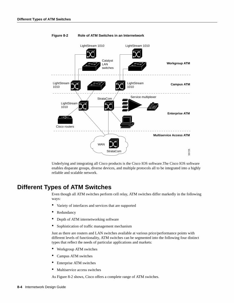
Integrated SolutionsThe trend in internetworking is to provide network designers greater flexibility in solving multipleinternetworking problems without creating multiple networks or writing off existing datacommunications investments. Routers can provide a reliable, secure network and act as a barrieragainst inadvertent broadcast storms in the local networks. Switches, which can be divided into twomain categories—LAN switches and WAN switches—can be deployed at the workgroup, campusbackbone, or WAN level, as shown in Figure 8-2.
8-4 Internetwork Design Guide
Different Types of ATM Switches
Figure 8-2 Role of ATM Switches in an Internetwork
Underlying and integrating all Cisco products is the Cisco IOS software.The Cisco IOS softwareenables disparate groups, diverse devices, and multiple protocols all to be integrated into a highlyreliable and scalable network.
Different Types of ATM SwitchesEven though all ATM switches perform cell relay, ATM switches differ markedly in the followingways:
• Variety of interfaces and services that are supported
• Redundancy
• Depth of ATM internetworking software
• Sophistication of traffic management mechanism
Just as there are routers and LAN switches available at various price/performance points withdifferent levels of functionality, ATM switches can be segmented into the following four distincttypes that reflect the needs of particular applications and markets:
• Workgroup ATM switches
• Campus ATM switches
• Enterprise ATM switches
• Multiservice access switches
As Figure 8-2 shows, Cisco offers a complete range of ATM switches.
LightStream 1010
CatalystLANswitches
LightStream1010
LightStream1010
LightStream1010
S57
25
Service multiplexer
Multiservice Access ATM
Enterprise ATM
Campus ATM
Workgroup ATM
Cisco routers
WAN
StrataCom
StrataCom
LightStream 1010
Designing ATM Internetworks 8-5
Different Types of ATM Switches
Workgroup and Campus ATM SwitchesWorkgroup ATM switches are characterized by having Ethernet switch ports, and an ATM uplink toconnect to a campus ATM switch. An example of a workgroup ATM switch is the CiscoCatalyst 5000.
Campus ATM switches are generally used for small-scale ATM backbones (for instance, to linkATM routers or LAN switches). This use of ATM switches can alleviate current backbonecongestion while enabling the deployment of such new services as virtual LANs (VLANs). Campusswitches need to support a wide variety of both local backbone and WAN types but beprice/performance optimized for the local backbone function. In this class of switches, ATM routingcapabilities that allow multiple switches to be tied together is very important. Congestion controlmechanisms for optimizing backbone performance is also important. The LightStream 1010 familyof ATM switches is an example of a campus ATM switch. For more information on deployingworkgroup and campus ATM switches in your internetwork, see the chapter, “Designing SwitchedLAN Internetworks.”
Enterprise ATM SwitchesEnterprise ATM switches are sophisticated multiservice devices that are designed to form the corebackbones of large, enterprise networks. They are intended to complement the role played by today’shigh-end multiprotocol routers. Enterprise ATM switches are used to interconnect campus ATMswitches. Enterprise-class switches, however, can act not only as ATM backbones but can serve asthe single point of integration for all of the disparate services and technology found in enterprisebackbones today. By integrating all of these services onto a common platform and a common ATMtransport infrastructure, network designers can gain greater manageability and eliminate the need formultiple overlay networks.
Cisco’s BPX/AXIS is a powerful broadband ATM switch designed to meet the demanding,high-traffic needs of a large private enterprise or public service provider. This chapter focuses on thiscategory of ATM switches.
Multiservice Access SwitchesBeyond private networks, ATM platforms will also be widely deployed by service providers both ascustomer premises equipment (CPE) and within public networks. Such equipment will be used tosupport multiple MAN and WAN services—for instance, Frame Relay switching, LANinterconnect, or public ATM services—on a common ATM infrastructure. Enterprise ATM switcheswill often be used in these public network applications because of their emphasis on high availabilityand redundancy, their support of multiple interfaces, and capability to integrate voice and data.

8-6 Internetwork Design Guide
ATM Overview
ATM OverviewThis section discusses the following ATM concepts:
• Structure of an ATM Network
• ATM Functional Layers
• ATM Addressing
• ATM Media
• ATM Data Exchange Interface
Note For more overview information on ATM, see theInternetworking Technology Overviewpublication.
Structure of an ATM NetworkATM is based on the concept of two end-point devices communicating by means of intermediateswitches. As Figure 8-3 shows, an ATM network is made up of a series of switches and end-pointdevices. The end-point devices can be ATM-attached end stations, ATM-attached servers, orATM-attached routers.
Figure 8-3 Components of an ATM Network
As Figure 8-3 shows, there are two types of interfaces in an ATM network:
• User-to-Network Interface (UNI)
• Network-to-Node Interface (NNI)
The UNI connection is made up of an end-point device and a private or public ATM switch. The NNIis the connection between two ATM switches. The UNI and NNI connections can be carried bydifferent physical connections.
In addition to the UNI and NNI protocols, the ATM Forum has defined a set of LAN Emulation(LANE) standards and a Private Network to Network Interface (PNNI) Phase 0 protocol. LANE isa technology network designers can use to internetwork legacy LANs such as Ethernet and TokenRing with ATM-attached devices. PNNI is based on UNI 3.0 signaling and static routes. The ATMForum is continuing work on a PNNI Phase 1 protocol that supports dynamic routing. Most LANEnetworks consist of multiple ATM switches and typically employ the PNNI protocol. The section“Role of LANE” later in this chapter discusses ATM LANE networks in detail.
UNI
UNI = User-to-Network InterfaceNNI = Network-to-Network Interface
NNI
S58
77
Designing ATM Internetworks 8-7
ATM Overview
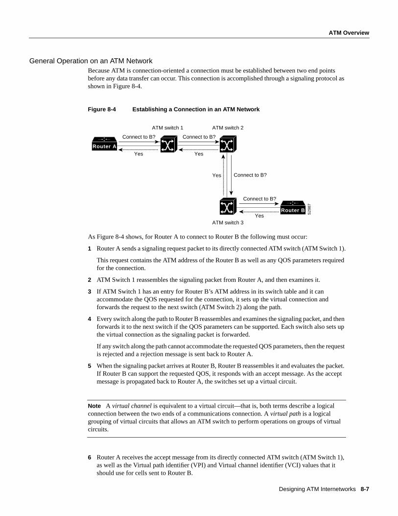
General Operation on an ATM NetworkBecause ATM is connection-oriented a connection must be established between two end pointsbefore any data transfer can occur. This connection is accomplished through a signaling protocol asshown in Figure 8-4.
Figure 8-4 Establishing a Connection in an ATM Network
As Figure 8-4 shows, for Router A to connect to Router B the following must occur:
1 Router A sends a signaling request packet to its directly connected ATM switch (ATM Switch 1).
This request contains the ATM address of the Router B as well as any QOS parameters requiredfor the connection.
2 ATM Switch 1 reassembles the signaling packet from Router A, and then examines it.
3 If ATM Switch 1 has an entry for Router B’s ATM address in its switch table and it canaccommodate the QOS requested for the connection, it sets up the virtual connection andforwards the request to the next switch (ATM Switch 2) along the path.
4 Every switch along the path to Router B reassembles and examines the signaling packet, and thenforwards it to the next switch if the QOS parameters can be supported. Each switch also sets upthe virtual connection as the signaling packet is forwarded.
If any switch along the path cannot accommodate the requested QOS parameters, then the requestis rejected and a rejection message is sent back to Router A.
5 When the signaling packet arrives at Router B, Router B reassembles it and evaluates the packet.If Router B can support the requested QOS, it responds with an accept message. As the acceptmessage is propagated back to Router A, the switches set up a virtual circuit.
Note A virtual channel is equivalent to a virtual circuit—that is, both terms describe a logicalconnection between the two ends of a communications connection. Avirtual path is a logicalgrouping of virtual circuits that allows an ATM switch to perform operations on groups of virtualcircuits.
6 Router A receives the accept message from its directly connected ATM switch (ATM Switch 1),as well as the Virtual path identifier (VPI) and Virtual channel identifier (VCI) values that itshould use for cells sent to Router B.
ATM switch 1 ATM switch 2
ATM switch 3
Connect to B?
Yes
Connect to B?
Yes
Connect to B?Yes
Connect to B?
Yes S29
87
Router B
Router A
8-8 Internetwork Design Guide
ATM Overview
Note ATM cells consist of 5 bytes of header information and 48 bytes of payload data. The VPIand VCI fields in the ATM header are used to route cells through ATM networks. The VPI and VCIfields of the cell header identify the next network segment that a cell needs to transmit on its way toits final destination.
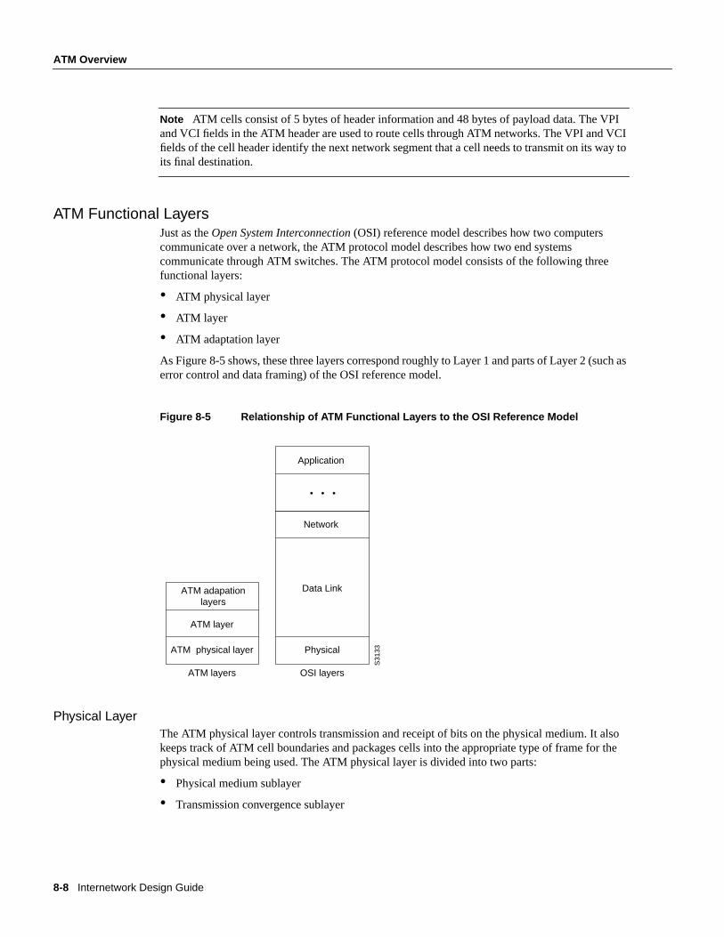
ATM Functional LayersJust as theOpen System Interconnection(OSI) reference model describes how two computerscommunicate over a network, the ATM protocol model describes how two end systemscommunicate through ATM switches. The ATM protocol model consists of the following threefunctional layers:
• ATM physical layer
• ATM layer
• ATM adaptation layer
As Figure 8-5 shows, these three layers correspond roughly to Layer 1 and parts of Layer 2 (such aserror control and data framing) of the OSI reference model.
Figure 8-5 Relationship of ATM Functional Layers to the OSI Reference Model
Physical LayerThe ATM physical layer controls transmission and receipt of bits on the physical medium. It alsokeeps track of ATM cell boundaries and packages cells into the appropriate type of frame for thephysical medium being used. The ATM physical layer is divided into two parts:
• Physical medium sublayer
• Transmission convergence sublayer
ATM adapationlayers
ATM layer
ATM physical layer
ATM layers
Data Link
Physical
OSI layers
Application
Network
S31
33
Designing ATM Internetworks 8-9
ATM Overview
Physical Medium SublayerThe physical medium sublayer is responsible for sending and receiving a continuous flow of bitswith associated timing information to synchronize transmission and reception. Because it includesonly physical-medium-dependent functions, its specification depends on the physical medium used.ATM can use any physical medium capable of carrying ATM cells. Some existing standards that cancarry ATM cells are SONET (Synchronous Optical Network)/SDH, DS-3/E3, 100-Mbps local fiber(Fiber Distributed Data Interface [FDDI] physical layer), and 155-Mbps local fiber (Fiber Channelphysical layer). Various proposals for use over twisted-pair wire are also under consideration.
Transmission Convergence SublayerThe transmission convergence sublayer is responsible for the following:
• Cell delineation—Maintains ATM cell boundaries.
• Header error control sequence generation and verification—Generates and checks the headererror control code to ensure valid data.
• Cell rate decoupling—Inserts or suppresses idle (unassigned) ATM cells to adapt the rate of validATM cells to the payload capacity of the transmission system.
• Transmission frame adaptation—Packages ATM cells into frames acceptable to the particularphysical-layer implementation.
• Transmission frame generation and recovery—Generates and maintains the appropriatephysical-layer frame structure.
ATM LayerThe ATM layer establishes virtual connections and passes ATM cells through the ATM network. Todo this, it uses the information contained in the header of each ATM cell. The ATM layer isresponsible for performing the following four basic functions:
• Multiplexing and demultiplexing the cells of different virtual connections. These connections areidentified by their VCI and VPI values.
• Translating the values of the VCI and VPI at the ATM switches or cross connects.
• Extracting and inserting the header before or after the cell is delivered to or from the higher ATMadaptation layer.
• Handling the implementation of a flow control mechanism at the UNI.
ATM Adaptation Layer (AAL)The AAL translates between the larger service data units (SDUs) (for example, video streams, anddata packets) of upper-layer processes and ATM cells. Specifically, the AAL receives packets fromupper-level protocols (such as AppleTalk, Internet Protocols [IP], and NetWare) and breaks theminto the 48-byte segments that form the payload field of an ATM cell. Several ATM adaptation layersare currently specified.
8-10 Internetwork Design Guide
ATM Overview
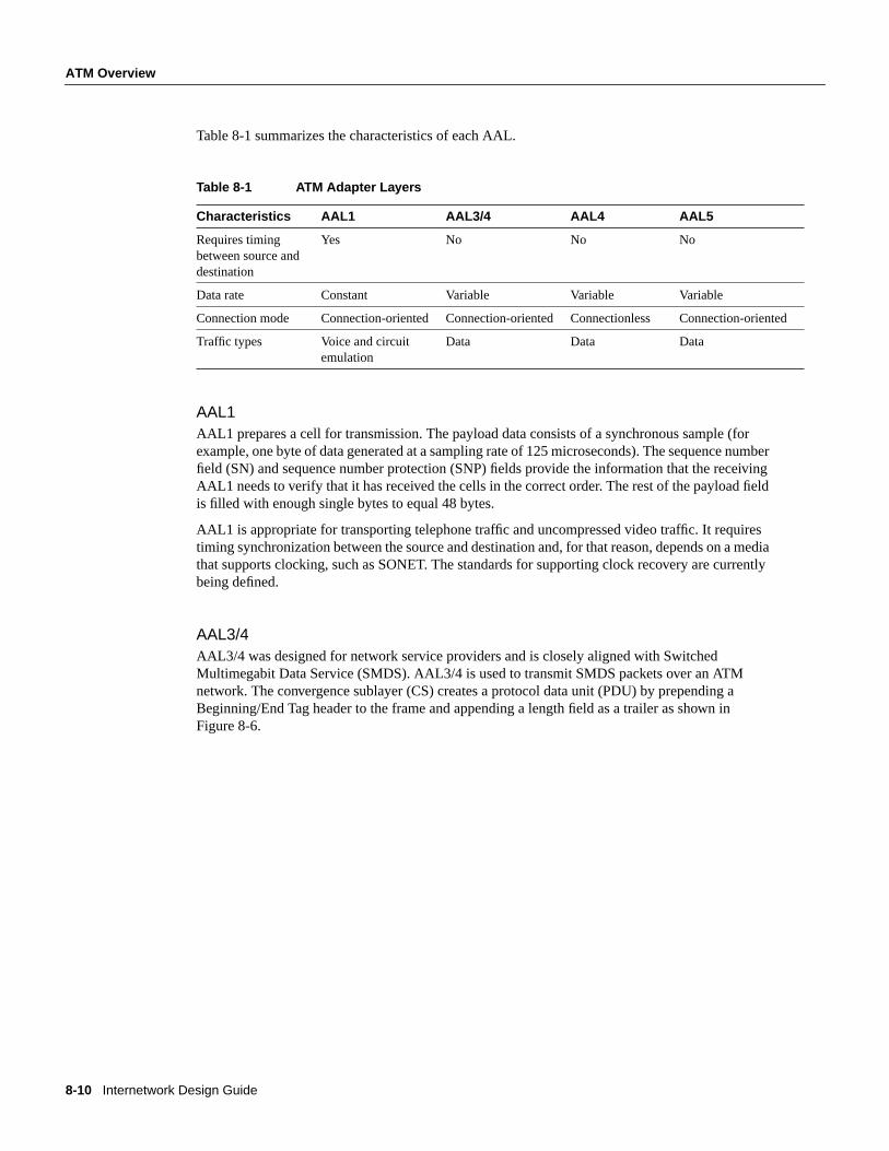
Table 8-1 summarizes the characteristics of each AAL.
Table 8-1 ATM Adapter Layers
AAL1AAL1 prepares a cell for transmission. The payload data consists of a synchronous sample (forexample, one byte of data generated at a sampling rate of 125 microseconds). The sequence numberfield (SN) and sequence number protection (SNP) fields provide the information that the receivingAAL1 needs to verify that it has received the cells in the correct order. The rest of the payload fieldis filled with enough single bytes to equal 48 bytes.
AAL1 is appropriate for transporting telephone traffic and uncompressed video traffic. It requirestiming synchronization between the source and destination and, for that reason, depends on a mediathat supports clocking, such as SONET. The standards for supporting clock recovery are currentlybeing defined.
AAL3/4AAL3/4 was designed for network service providers and is closely aligned with SwitchedMultimegabit Data Service (SMDS). AAL3/4 is used to transmit SMDS packets over an ATMnetwork. The convergence sublayer (CS) creates a protocol data unit (PDU) by prepending aBeginning/End Tag header to the frame and appending a length field as a trailer as shown inFigure 8-6.
Characteristics AAL1 AAL3/4 AAL4 AAL5
Requires timingbetween source anddestination
Yes No No No
Data rate Constant Variable Variable Variable
Connection mode Connection-oriented Connection-oriented Connectionless Connection-oriented
Traffic types Voice and circuitemulation
Data Data Data
Designing ATM Internetworks 8-11
ATM Overview
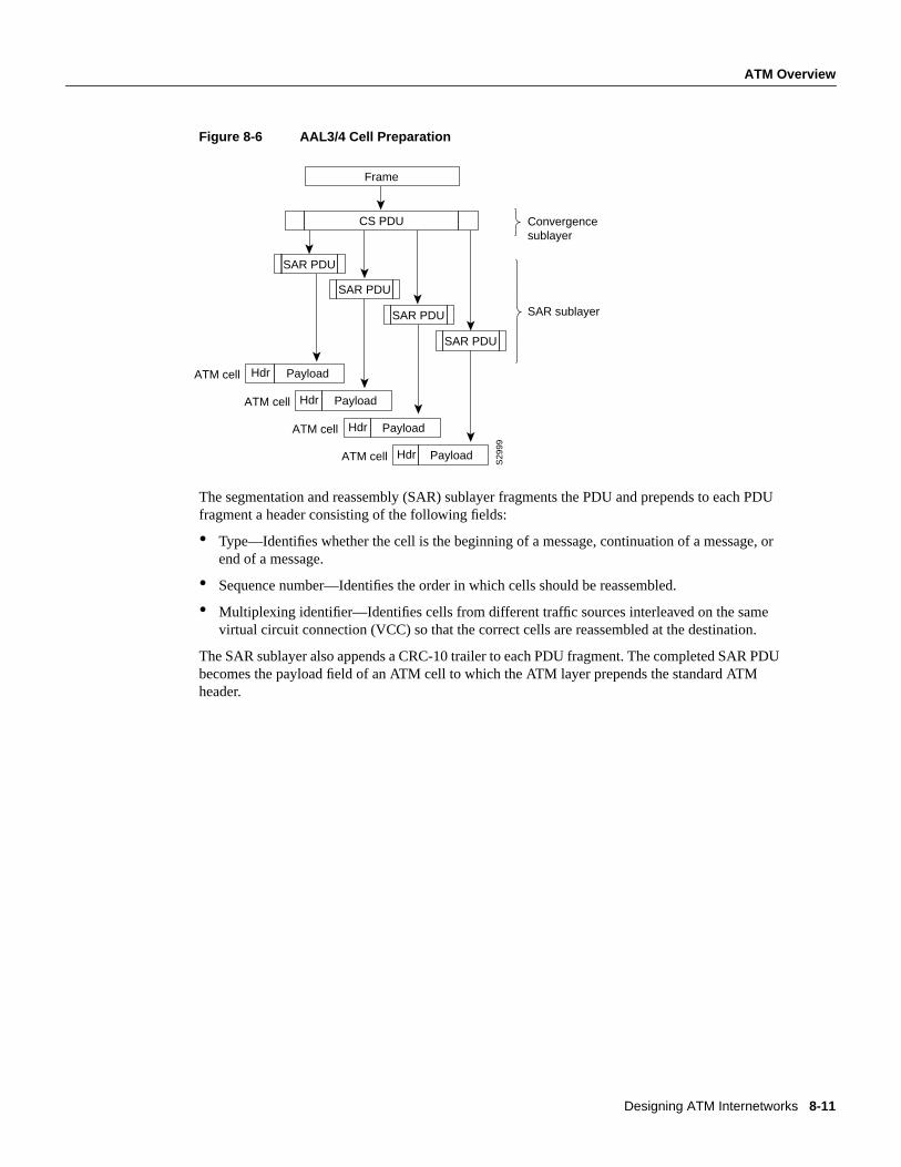
Figure 8-6 AAL3/4 Cell Preparation
The segmentation and reassembly (SAR) sublayer fragments the PDU and prepends to each PDUfragment a header consisting of the following fields:
• Type—Identifies whether the cell is the beginning of a message, continuation of a message, orend of a message.
• Sequence number—Identifies the order in which cells should be reassembled.
• Multiplexing identifier—Identifies cells from different traffic sources interleaved on the samevirtual circuit connection (VCC) so that the correct cells are reassembled at the destination.
The SAR sublayer also appends a CRC-10 trailer to each PDU fragment. The completed SAR PDUbecomes the payload field of an ATM cell to which the ATM layer prepends the standard ATMheader.
Frame
CS PDU
SAR PDU
SAR PDU
SAR PDU
SAR PDU
Payload
S29
99
HdrATM cell
PayloadATM cell
PayloadATM cell
PayloadATM cell
Convergencesublayer
SAR sublayer
Hdr
Hdr
Hdr
8-12 Internetwork Design Guide
ATM Overview
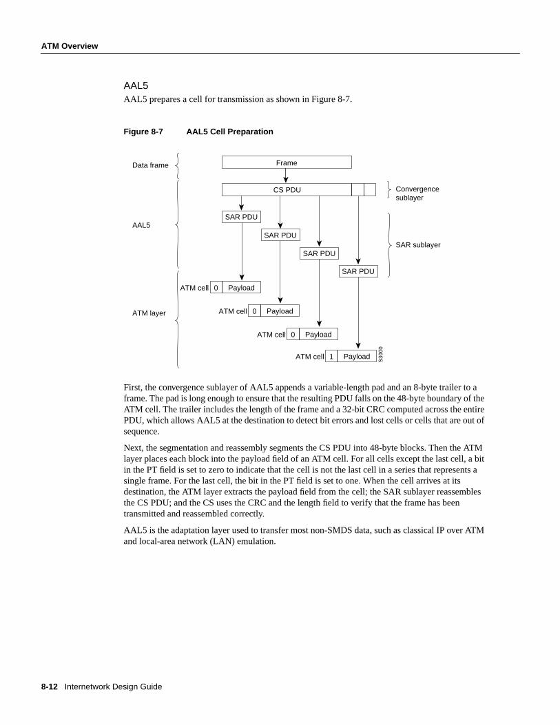
AAL5AAL5 prepares a cell for transmission as shown in Figure 8-7.
Figure 8-7 AAL5 Cell Preparation
First, the convergence sublayer of AAL5 appends a variable-length pad and an 8-byte trailer to aframe. The pad is long enough to ensure that the resulting PDU falls on the 48-byte boundary of theATM cell. The trailer includes the length of the frame and a 32-bit CRC computed across the entirePDU, which allows AAL5 at the destination to detect bit errors and lost cells or cells that are out ofsequence.
Next, the segmentation and reassembly segments the CS PDU into 48-byte blocks. Then the ATMlayer places each block into the payload field of an ATM cell. For all cells except the last cell, a bitin the PT field is set to zero to indicate that the cell is not the last cell in a series that represents asingle frame. For the last cell, the bit in the PT field is set to one. When the cell arrives at itsdestination, the ATM layer extracts the payload field from the cell; the SAR sublayer reassemblesthe CS PDU; and the CS uses the CRC and the length field to verify that the frame has beentransmitted and reassembled correctly.
AAL5 is the adaptation layer used to transfer most non-SMDS data, such as classical IP over ATMand local-area network (LAN) emulation.
Data frame
AAL5
Frame
CS PDU
SAR PDU
Payload
ATM layer
SAR PDU
SAR PDU
SAR PDU
S30
00
ATM cell 0
PayloadATM cell 0
PayloadATM cell 0
PayloadATM cell 1
Convergencesublayer
SAR sublayer
Designing ATM Internetworks 8-13
ATM Overview
ATM AddressingThe ATM Forum has adapted the subnetwork model of addressing in which the ATM layer isresponsible for mapping network-layer addresses to ATM addresses. Several ATM address formatshave been developed. Public ATM networks typically use E.164 numbers, which are also used byNarrowband ISDN (N-ISDN) networks.
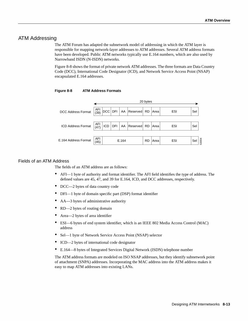
Figure 8-8 shows the format of private network ATM addresses. The three formats are Data CountryCode (DCC), International Code Designator (ICD), and Network Service Access Point (NSAP)encapsulated E.164 addresses.
Figure 8-8 ATM Address Formats
Fields of an ATM AddressThe fields of an ATM address are as follows:
• AFI—1 byte of authority and format identifier. The AFI field identifies the type of address. Thedefined values are 45, 47, and 39 for E.164, ICD, and DCC addresses, respectively.
• DCC—2 bytes of data country code
• DFI—1 byte of domain specific part (DSP) format identifier
• AA—3 bytes of administrative authority
• RD—2 bytes of routing domain
• Area—2 bytes of area identifier
• ESI—6 bytes of end system identifier, which is an IEEE 802 Media Access Control (MAC)address
• Sel—1 byte of Network Service Access Point (NSAP) selector
• ICD—2 bytes of international code designator
• E.164—8 bytes of Integrated Services Digital Network (ISDN) telephone number
The ATM address formats are modeled on ISO NSAP addresses, but they identify subnetwork pointof attachment (SNPA) addresses. Incorporating the MAC address into the ATM address makes iteasy to map ATM addresses into existing LANs.
AFI(39) DCC DFI AA Reserved RD Area ESI Sel
AFI(47) ICD DFI AA Reserved RD Area ESI Sel
AFI(45) RD Area ESI SelE.164
20 bytes
DCC Address Format
ICD Address Format
E.164 Address Format
S30
04

8-14 Internetwork Design Guide
ATM Overview
ATM MediaThe ATM Forum has defined multiple standards for encoding ATM over various types of media.Table 8-2 lists the framing type and data rates for the various media, including unshielded twisted-pair (UTP) and shielded twisted-pair (STP) cable.
Table 8-2 ATM Physical Rates
Because the FDDI chipset standard, TAXI 4B/5B, was readily available, the ATM Forumencouraged initial ATM development efforts by endorsing TAXI 4B/5B as one of the first ATMmedia encoding standards. Today, however, the most common fiber interface is STS3c/STM.
There are two standards for running ATM over copper cable: UTP-3 and UTP-5. The UTP-5specification supports 155 Mbps with NRZI encoding, while the UTP-3 specification supports51 Mbps with CAP-16 encoding. CAP-16 is more difficult to implement, so, while it may be cheaperto wire with UTP-3 cable, workstation cards designed for CAP-16-based UTP-3 may be moreexpensive and will offer less bandwidth.
Because ATM is designed to run over fiber and copper cable, investments in these media today willmaintain their value when networks migrate to full ATM implementations as ATM technologymatures.
Media
FramingData Rate(Mbps)
Multimode Fiber
SingleModeFiber
Coaxial Cable UTP-3 UTP-5 STP
DS-1 1.544
E1 2.048
DS-3 45
E3 34
STS-1 51
SONET STS3c
SDH STM1
155
SONET STS12c
SDH STM4
622
TAXI 4B/5B 100
8B/10B
(Fiber Channel)
155
Designing ATM Internetworks 8-15
ATM Overview
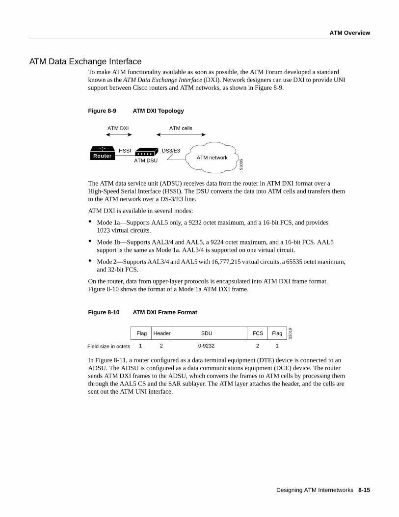
ATM Data Exchange InterfaceTo make ATM functionality available as soon as possible, the ATM Forum developed a standardknown as theATM Data Exchange Interface (DXI). Network designers can use DXI to provide UNIsupport between Cisco routers and ATM networks, as shown in Figure 8-9.
Figure 8-9 ATM DXI Topology
The ATM data service unit (ADSU) receives data from the router in ATM DXI format over aHigh-Speed Serial Interface (HSSI). The DSU converts the data into ATM cells and transfers themto the ATM network over a DS-3/E3 line.
ATM DXI is available in several modes:
• Mode 1a—Supports AAL5 only, a 9232 octet maximum, and a 16-bit FCS, and provides1023 virtual circuits.
• Mode 1b—Supports AAL3/4 and AAL5, a 9224 octet maximum, and a 16-bit FCS. AAL5support is the same as Mode 1a. AAL3/4 is supported on one virtual circuit.
• Mode 2—Supports AAL3/4 and AAL5 with 16,777,215 virtual circuits, a 65535 octet maximum,and 32-bit FCS.
On the router, data from upper-layer protocols is encapsulated into ATM DXI frame format.Figure 8-10 shows the format of a Mode 1a ATM DXI frame.
Figure 8-10 ATM DXI Frame Format
In Figure 8-11, a router configured as a data terminal equipment (DTE) device is connected to anADSU. The ADSU is configured as a data communications equipment (DCE) device. The routersends ATM DXI frames to the ADSU, which converts the frames to ATM cells by processing themthrough the AAL5 CS and the SAR sublayer. The ATM layer attaches the header, and the cells aresent out the ATM UNI interface.
Router
ATM DXI ATM cells
HSSI
ATM DSU
DS3/E3ATM network
S30
05
Flag Header SDU FCS Flag
1 2 0-9232 2 1Field size in octets
S30
19
8-16 Internetwork Design Guide
ATM Overview
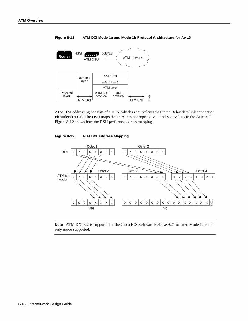
Figure 8-11 ATM DXI Mode 1a and Mode 1b Protocol Architecture for AAL5
ATM DXI addressing consists of a DFA, which is equivalent to a Frame Relay data link connectionidentifier (DLCI). The DSU maps the DFA into appropriate VPI and VCI values in the ATM cell.Figure 8-12 shows how the DSU performs address mapping.
Figure 8-12 ATM DXI Address Mapping
Note ATM DXI 3.2 is supported in the Cisco IOS Software Release 9.21 or later. Mode 1a is theonly mode supported.
RouterHSSI
ATM DSU
DS3/E3ATM network
S30
20
Physicallayer
Data linklayer
ATM DXIphysical
UNIphysical
AAL5 CS
AAL5 SAR
ATM layer
ATM DXI ATM UNI
8 7 6 5 4 3 2 1 8 7 6 5 4 3 2 1
8 7 6 5 4 3 2 1 8 7 6 5 4 3 2 1 8 7 6 5 4 3 2 1
0 0 0 0 X X X X 0 0 0 0 0 0 0 0 0 0 X X X X X X
DFA
ATM cellheader
Octet 1 Octet 2
Octet 2 Octet 3 Octet 4
VPI VCIS
3021
Designing ATM Internetworks 8-17
Role of LANE
Role of LANEThe ATM Forum has defined a standard for LANE. LANE is a technology that network designerscan deploy to internetwork their legacy LANs (for example, Ethernet and Token Ring LANs), withATM-attached devices. LANE uses MAC encapsulation (OSI Layer 2) because this approachsupports the largest number of existing OSI Layer 3 protocols. The end result is that all devicesattached to an emulated LAN (ELAN) appear to be on one bridged segment. In this way, AppleTalk,IPX, and other protocols should have similar performance characteristics as in a traditional bridgedenvironment.
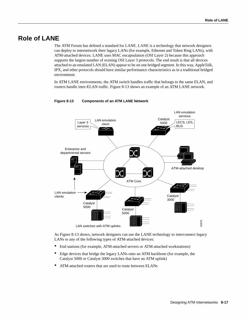
In ATM LANE environments, the ATM switch handles traffic that belongs to the same ELAN, androuters handle inter-ELAN traffic. Figure 8-13 shows an example of an ATM LANE network.
Figure 8-13 Components of an ATM LANE Network
As Figure 8-13 shows, network designers can use the LANE technology to interconnect legacyLANs to any of the following types of ATM-attached devices:
• End stations (for example, ATM-attached servers or ATM-attached workstations)
• Edge devices that bridge the legacy LANs onto an ATM backbone (for example, theCatalyst 5000 or Catalyst 3000 switches that have an ATM uplink)
• ATM-attached routers that are used to route between ELANs
ATM Core
S58
76
ATM-attached desktop
Catalyst3000
Catalyst5000
Catalyst 5000
Enterprise anddepartmental servers
LAN emulationclient
Catalyst5000
LAN emulationservices
LAN switches with ATM uplinks
LAN emulationclients
Layer 3 services
LECS, LES,BUS
8-18 Internetwork Design Guide
Role of LANE
LANE ComponentsLANE components include the following:
• LAN emulation client (LEC)—End systems that support LANE, such as network interface card(NIC)-connected workstations, LAN switches with ATM uplinks (for example, the Catalystfamily of switches), and Cisco 7500, 7000, 4500, and 4000 series routers that support ATMattachment, require the implementation of a LEC. The LEC emulates an interface to a legacyLAN to the higher-level protocols. It performs data forwarding, address resolution, andregistration of MAC addresses with the LANE server and communicates with other LECs viaATM virtual channel connections (VCCs).
• LAN emulation configuration server (LECS)—The LECS maintains a database of ELANs andthe ATM addresses of the LESs that control the ELANs. It accepts queries from LECs andresponds with the ATM address of the LES that serves the appropriate ELAN/VLAN. Thisdatabase is defined and maintained by the network administrator.
The following is an example of this database.
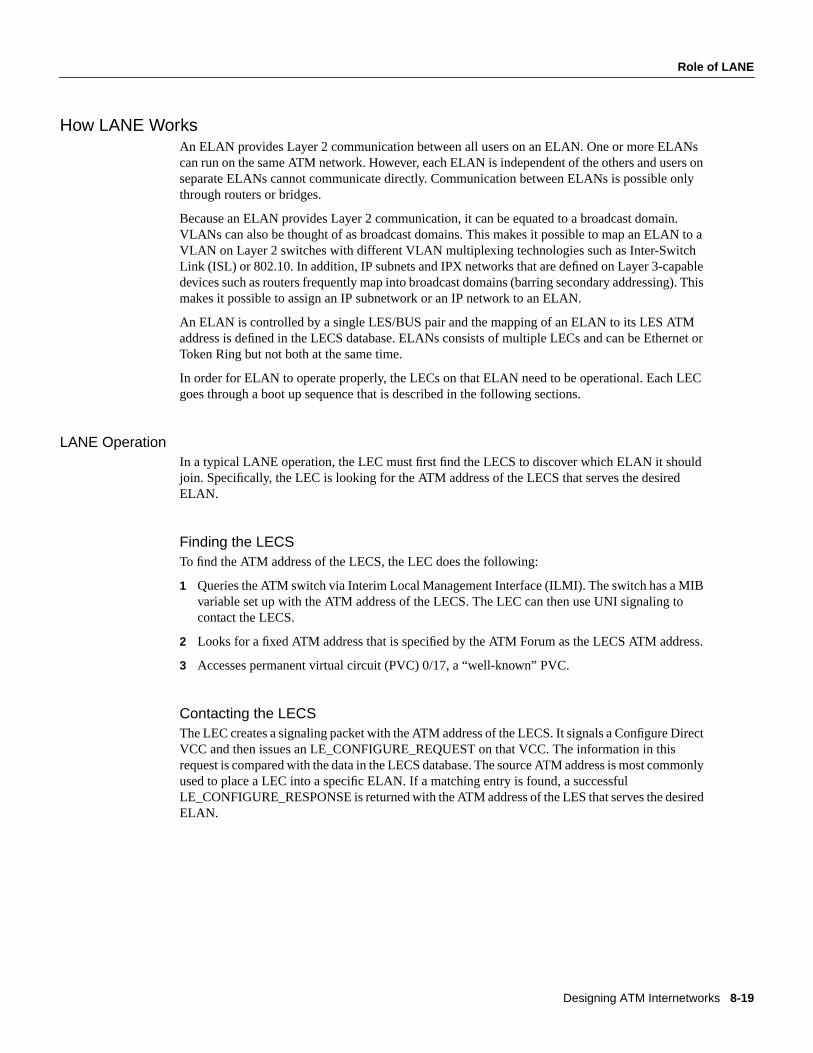
• LAN emulation server (LES)—The LES provides a central control point for all LECs. LECsmaintain a Control Direct VCC to the LES to forward registration and control information. TheLES maintains a point-to-multipoint VCC, known as theControl Distribute VCC, to all LECs.The Control Distribute VDD is used only to forward control information. As new LECs join theATM ELAN, each LEC is added as a leaf to the control distribute tree.
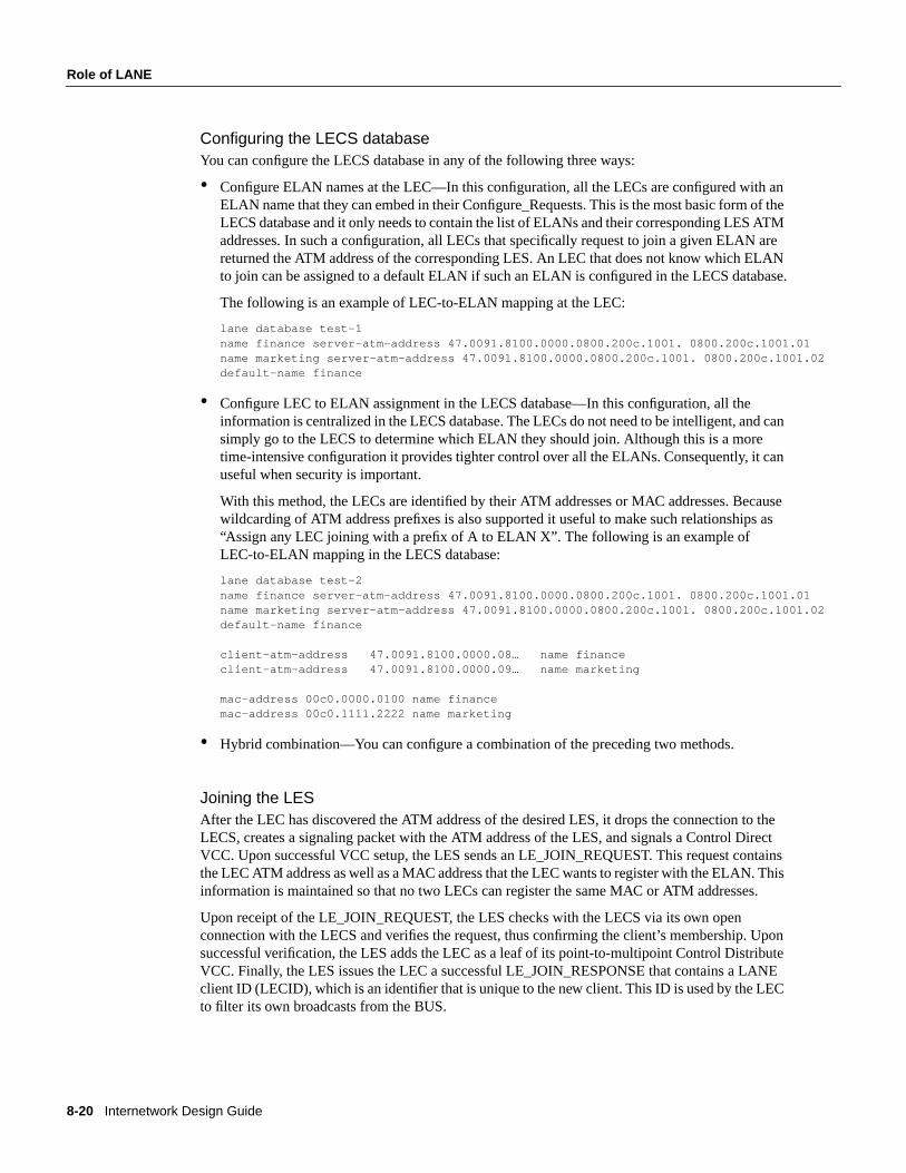
• Broadcast and unknown Server (BUS)—The BUS acts as a central point for distributingbroadcasts and multicasts. ATM is essentially a point-to-point technology without “any-to-any”or “broadcast” support. LANE solves this problem by centralizing the broadcast support in theBUS. Each LEC must set up a Multicast Send VCC to the BUS. The BUS then adds the LEC asa leaf to its point-to-multipoint VCC (known as theMulticast Forward VCC).
The BUS also acts as a multicast server. LANE is defined on ATM adaptation layer 5 (AAL5),which specifies a simple trailer to be appended to a frame before it is broken into ATM cells. Theproblem is that there is no way to differentiate between ATM cells from different senders whenmultiplexed on a virtual channel. It is assumed that cells received will be in sequence, and whenthe End of Message (EOM) cell arrives, you should just have to reassemble all of the cells thathave already arrived.
The BUS takes the sequence of cells on each Multicast Send VCC and reassembles them intoframes. When a full frame is received, it is queued for sending to all of the LECs on the MulticastForward VCC. This way, all the cells from a particular data frame can be guaranteed to be sentin order and not interleaved with cells from any other data frames on the point-to-multipointVCC.
Note that because LANE is defined at OSI Layer 2, the LECS is the only security checkpointavailable. Once it has been told where to find the LES and it has successfully joined the ELAN, theLEC is free to send any traffic (whether malicious or not) into the bridged ELAN. The only place forany OSI Layer 3 security filters is in the router that routes this ELAN to other ELANs. Therefore,the larger the ELAN, the greater the exposure to security violations.
ELAN Name LES ATM Address
finance 47.0091.8100.0000.0800.200c.1001. 0800.200c.1001.01
marketing 47.0091.8100.0000.0800.200c.1001. 0800.200c.1001.02
Designing ATM Internetworks 8-19
Role of LANE
How LANE WorksAn ELAN provides Layer 2 communication between all users on an ELAN. One or more ELANscan run on the same ATM network. However, each ELAN is independent of the others and users onseparate ELANs cannot communicate directly. Communication between ELANs is possible onlythrough routers or bridges.
Because an ELAN provides Layer 2 communication, it can be equated to a broadcast domain.VLANs can also be thought of as broadcast domains. This makes it possible to map an ELAN to aVLAN on Layer 2 switches with different VLAN multiplexing technologies such as Inter-SwitchLink (ISL) or 802.10. In addition, IP subnets and IPX networks that are defined on Layer 3-capabledevices such as routers frequently map into broadcast domains (barring secondary addressing). Thismakes it possible to assign an IP subnetwork or an IP network to an ELAN.
An ELAN is controlled by a single LES/BUS pair and the mapping of an ELAN to its LES ATMaddress is defined in the LECS database. ELANs consists of multiple LECs and can be Ethernet orToken Ring but not both at the same time.
In order for ELAN to operate properly, the LECs on that ELAN need to be operational. Each LECgoes through a boot up sequence that is described in the following sections.
LANE OperationIn a typical LANE operation, the LEC must first find the LECS to discover which ELAN it shouldjoin. Specifically, the LEC is looking for the ATM address of the LECS that serves the desiredELAN.
Finding the LECSTo find the ATM address of the LECS, the LEC does the following:
1 Queries the ATM switch via Interim Local Management Interface (ILMI). The switch has a MIBvariable set up with the ATM address of the LECS. The LEC can then use UNI signaling tocontact the LECS.
2 Looks for a fixed ATM address that is specified by the ATM Forum as the LECS ATM address.
3 Accesses permanent virtual circuit (PVC) 0/17, a “well-known” PVC.
Contacting the LECSThe LEC creates a signaling packet with the ATM address of the LECS. It signals a Configure DirectVCC and then issues an LE_CONFIGURE_REQUEST on that VCC. The information in thisrequest is compared with the data in the LECS database. The source ATM address is most commonlyused to place a LEC into a specific ELAN. If a matching entry is found, a successfulLE_CONFIGURE_RESPONSE is returned with the ATM address of the LES that serves the desiredELAN.
8-20 Internetwork Design Guide
Role of LANE
Configuring the LECS databaseYou can configure the LECS database in any of the following three ways:
• Configure ELAN names at the LEC—In this configuration, all the LECs are configured with anELAN name that they can embed in their Configure_Requests. This is the most basic form of theLECS database and it only needs to contain the list of ELANs and their corresponding LES ATMaddresses. In such a configuration, all LECs that specifically request to join a given ELAN arereturned the ATM address of the corresponding LES. An LEC that does not know which ELANto join can be assigned to a default ELAN if such an ELAN is configured in the LECS database.
The following is an example of LEC-to-ELAN mapping at the LEC:
lane database test-1name finance server-atm-address 47.0091.8100.0000.0800.200c.1001. 0800.200c.1001.01name marketing server-atm-address 47.0091.8100.0000.0800.200c.1001. 0800.200c.1001.02default-name finance
• Configure LEC to ELAN assignment in the LECS database—In this configuration, all theinformation is centralized in the LECS database. The LECs do not need to be intelligent, and cansimply go to the LECS to determine which ELAN they should join. Although this is a moretime-intensive configuration it provides tighter control over all the ELANs. Consequently, it canuseful when security is important.
With this method, the LECs are identified by their ATM addresses or MAC addresses. Becausewildcarding of ATM address prefixes is also supported it useful to make such relationships as“Assign any LEC joining with a prefix of A to ELAN X”. The following is an example ofLEC-to-ELAN mapping in the LECS database:
lane database test-2name finance server-atm-address 47.0091.8100.0000.0800.200c.1001. 0800.200c.1001.01name marketing server-atm-address 47.0091.8100.0000.0800.200c.1001. 0800.200c.1001.02default-name finance
client-atm-address 47.0091.8100.0000.08… name financeclient-atm-address 47.0091.8100.0000.09… name marketing
mac-address 00c0.0000.0100 name financemac-address 00c0.1111.2222 name marketing
• Hybrid combination—You can configure a combination of the preceding two methods.
Joining the LESAfter the LEC has discovered the ATM address of the desired LES, it drops the connection to theLECS, creates a signaling packet with the ATM address of the LES, and signals a Control DirectVCC. Upon successful VCC setup, the LES sends an LE_JOIN_REQUEST. This request containsthe LEC ATM address as well as a MAC address that the LEC wants to register with the ELAN. Thisinformation is maintained so that no two LECs can register the same MAC or ATM addresses.
Upon receipt of the LE_JOIN_REQUEST, the LES checks with the LECS via its own openconnection with the LECS and verifies the request, thus confirming the client’s membership. Uponsuccessful verification, the LES adds the LEC as a leaf of its point-to-multipoint Control DistributeVCC. Finally, the LES issues the LEC a successful LE_JOIN_RESPONSE that contains a LANEclient ID (LECID), which is an identifier that is unique to the new client. This ID is used by the LECto filter its own broadcasts from the BUS.
Designing ATM Internetworks 8-21
Role of LANE
Figure 8-14 shows examples of LES connections.
Figure 8-14 LAN Emulation Server (LES) Connections
Finding the BUSAfter the LEC has successfully joined the LES, its first task is to find the ATM address of the BUSand join the broadcast group. The LEC creates an LE_ARP_REQUEST packet with the MACaddress 0xFFFFFFFF. This special LE_ARP packet is sent on the Control Direct VCC to the LES.The LES recognizes that the LEC is looking for the BUS, responds with the ATM address of theBUS, and forwards that response on the Control Distribute VCC.
Joining the BUSWhen the LEC has the ATM address of the BUS, its next action is to create a signaling packet withthat address and signal a Multicast Send VCC. Upon receipt of the signaling request, the BUS addsthe LEC as a leaf on its point-to-multipoint Multicast Forward VCC. At this time, the LEC hasbecome a member of the ELAN. Figure 8-15 shows examples of BUS connections.
AIP
Control Distribute VCC(Point to Multipoint)
Control Direct VCC(Unidirectional)
LAN EmulationServer (LES)
S44
53
8-22 Internetwork Design Guide
Role of LANE
Figure 8-15 BUS Connections
Address ResolutionThe real value of LANE is the ATM forwarding path that it provides for unicast traffic betweenLECs. When a LEC has a data packet to send to an unknown destination, it issues anLE_ARP_REQUEST to the LES on the Control Direct VCC. The LES forwards the request on theControl Distribute VCC, so all LEC stations hear it. In parallel, the unicast data packets are sent tothe BUS, to be forwarded to all endpoints. This “flooding” is not the optimal path for unicast traffic,and this transmission path is rate-controlled to 10 packets per second (per the LANE standard).Unicast packets continue using the BUS until the LE_ARP_REQUEST has been resolved.
If bridging or switching devices with LEC software participate in the ELAN, they translate andforward the ARP on their LAN interfaces. One of the LECs should issue an LE_ARP_RESPONSEand send it to the LES, which forwards it to the Control Distribute VCC so that all LECs can learnthe new MAC-to-ATM address binding.
When the requesting LEC receives the LE_ARP_RESPONSE, it has the ATM address of the LECthat represents the MAC address being sought. The LEC should now signal the other LEC directlyand set up a Data Direct VCC that will be used for unicast data between the LECs.
While waiting for LE_ARP resolution, the LEC forwards unicasts to the BUS. With LE_ARPresolution, a new “optimal” path becomes available. If the LEC switches immediately to the newpath, it runs the risk of packets arriving out of order. To guard against this situation, the LANEstandard provides a flush packet.
When the Data Direct VCC becomes available, the LEC generates a flush packet and sends it to theBUS. When the LEC receives its own flush packet on the Multicast Forward VCC, it knows that allpreviously sent unicasts must have already been forwarded. It is now safe to begin using the DataDirect VCC.
Figure 8-16 shows an example of a fully connected ELAN.
AIP
Bus Forward VCC(Point to Multipoint)
Bus Send VCC(Unidirectional)
Broadcast andUnknown Server
S44
52

Designing ATM Internetworks 8-23
LANE Implementation
Figure 8-16 Fully Connected ELAN
LANE ImplementationAs Table 8-3 indicates, the LANE functionality (the LECS, LEC, LES, and BUS) can beimplemented in different Cisco devices.
Table 8-3 Cisco LANE Implementation
These functions will be defined on ATM physical interfaces and subinterfaces. A subinterface canbe defined as a logical interface and is a part of a physical interface such as an Optical Carrier 3(OC-3) fiber. ATM interfaces on the Cisco routers and the ATM module on the Catalyst 5000 switchcan be logically divided into up to 255 logical subinterfaces. On the Catalyst 3000 switch, althoughthe same Cisco IOS Software code is used, the subinterface concept does not apply. The LEC can beconfigured using the menu-driven interface.
This section examines the implementation of ATM LANE networks and covers the following topics:
• LANE Design Considerations
• LANE Redundancy
Cisco Product Available LANE Components Required Software Release
Family of Catalyst 5000 switches LECS, LES, BUS, LEC ATM Module Software Version 2.0 or later
Family of Catalyst 3000 switches LECS, LES, BUS, LEC ATM Module Software Version 2.1 or later
Family of Cisco 7000 routers LECS, LES, BUS, LEC Cisco IOS Software Release 11.0 or later
Family of Cisco 7500 routers LECS, LES, BUS, LEC Cisco IOS Software Release 11.1 or later
Family of Cisco 4500 and 4000 routers LECS, LES, BUS, LEC Cisco IOS Software Release 11.1 or later
S44
51
AIP SubinterfacesLES BUS
Client Direct VCC(Bidirectional)
8-24 Internetwork Design Guide
LANE Implementation
LANE Design ConsiderationsThe following are some general LANE design considerations:
• The AIP is limited to 60K packets per second (pps) bidirectionally.
• One active LECS supports all ELANs.
• In each ELAN, there is one LES/BUS pair and some number of LECs.
• The LES and BUS functionality must be defined on the same subinterface and cannot beseparated.
• There can be only one active LES/BUS pair per subinterface.
• There can be only one LES/BUS pair per ELAN.
• The current LANE Phase 1 standard does not provide for any LES/BUS redundancy.
• The LECS and LES/BUS can be different routers, bridges, or workstations.
• VCCs can be either switched virtual circuits (SVCs) or permanent virtual circuits (PVCs),although PVC design configuration and complexity might make anything more than a very smallnetwork prohibitively unmanageable and complex.
• When defining VLANs with the Catalyst 5000 switch, each VLAN should be assigned to adifferent ELAN. The LES/BUS pair for each ELAN can reside on any of the following:
— Different subinterfaces on the same AIP
— Different AIPs in the same router
— Different AIPs in different routers
• There can be only one LEC per subinterface. If a LEC and a LES/BUS pair share a subinterface,they are (by definition) in the same ELAN.
• If a LEC on a router subinterface is assigned an IP, IPX, or AppleTalk address, that protocol isroutable over that LEC. If there are multiple LECs on a router and they are assigned protocoladdresses, routing will occur between the ELANs. For routing between ELANs to functioncorrectly, an ELAN should be in only one subnet for a particular protocol.
PNNI in LANE NetworksNetwork designers can deploy PNNI as a Layer 2 routing protocol for bandwidth management,traffic distribution, and path redundancy for LANE networks. PNNI is an ATM routing protocol usedfor routing call setups and is implemented in the ATM switches. Most LANE networks consist ofmultiple ATM switches and typically employ the PNNI protocol.
Note Although PNNI is an advanced routing protocol and supports QOS-based routing, thisparticular aspect of PNNI is not discussed in this chapter because most LANE networks are basedon the best-effort traffic category.
The LightStream 1010 ATM switch supports some PNNI-related features that can be useful inscaling LANE networks:
• To load balance call setup requests across multiple paths between two end stations
• To load balance call setups across multiple parallel links
Designing ATM Internetworks 8-25
LANE Implementation
• To support link and path redundancy with fast convergence
• To provide excellent call setup performance across multiple hops using the background routingfeature
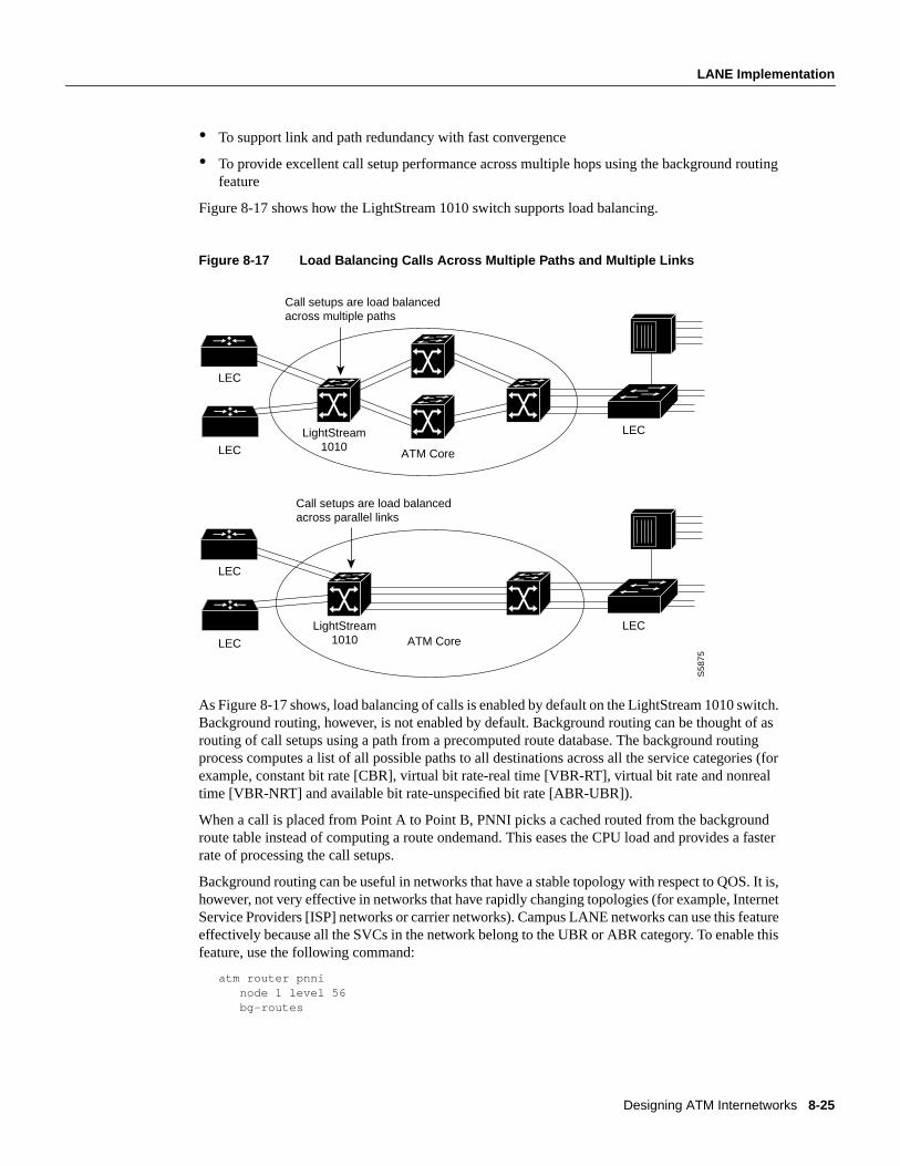
Figure 8-17 shows how the LightStream 1010 switch supports load balancing.
Figure 8-17 Load Balancing Calls Across Multiple Paths and Multiple Links
As Figure 8-17 shows, load balancing of calls is enabled by default on the LightStream 1010 switch.Background routing, however, is not enabled by default. Background routing can be thought of asrouting of call setups using a path from a precomputed route database. The background routingprocess computes a list of all possible paths to all destinations across all the service categories (forexample, constant bit rate [CBR], virtual bit rate-real time [VBR-RT], virtual bit rate and nonrealtime [VBR-NRT] and available bit rate-unspecified bit rate [ABR-UBR]).
When a call is placed from Point A to Point B, PNNI picks a cached routed from the backgroundroute table instead of computing a route ondemand. This eases the CPU load and provides a fasterrate of processing the call setups.
Background routing can be useful in networks that have a stable topology with respect to QOS. It is,however, not very effective in networks that have rapidly changing topologies (for example, InternetService Providers [ISP] networks or carrier networks). Campus LANE networks can use this featureeffectively because all the SVCs in the network belong to the UBR or ABR category. To enable thisfeature, use the following command:
atm router pnni node 1 level 56 bg-routes
LEC
LightStream1010LEC
LEC
S58
75
ATM Core
Call setups are load balanced across multiple paths
LEC
LightStream1010LEC
LECATM Core
Call setups are load balanced across parallel links
8-26 Internetwork Design Guide
LANE Implementation
The current implementation of PNNI on the LightStream 1010 switch does not support hierarchy.Consequently, the LightStream 1010 switch is expected to scale up to 100 to 200 nodes (ATMswitches) depending on the interconnections. Theoretically, PNNI with hierarchy is expected tosupport an unlimited number of nodes.
Scaling an ELAN—Spanning-Tree Protocol IssuesSpanning-Tree Protocol is implemented in Layer 2 switches/bridges to prevent temporary loops innetworks with redundant links. Because an LEC essentially bridges Ethernet/Token Ring traffic overan ATM backbone, the Spanning-Tree Bridge Protocol Data Units (BPDUs) are transmitted over theentire ELAN. The ATM network appears as a shared Ethernet/Token Ring network to thespanning-tree process at the edge Layer 2 switches.
The spanning-tree topology of a LANE-based network is substantially simpler than a pureframe-switched network that employs the Spanning-Tree Protocol. It follows that spanning-treeconvergence times, which can be a major issue in large frame-switched networks, can be less of anissue in LANE networks. Note that Spanning Tree must reconverge if there are failures at the edgedevices or inside the ATM network. If there is a need to tune the convergence time to a lower orhigher value, the forward delay parameter can be used.
LANE RedundancyAlthough LANE allows network designers to connect their legacy LANs to an ATM network, LANEVersion 1.0 does not define mechanisms for building redundancy and fault tolerance into the LANEservices. Consequently, this makes the LANE services a single point of failure. Moreover, routerredundancy and path/link redundancy are also issues that the network designer needs to consider.
Network designers can use the following techniques to build fault-tolerant and resilient LANEnetworks:
• Simple Server Replication Protocol (SSRP) for LANE Services redundancy that works withCisco and any third-party LECs.
• Hot Standby Router Protocol (HSRP) over LANE provides redundancy for the default routerconfigured at IP end stations.
• Dual PHY LANE card on the Catalyst 5000 switch, or multiple ATM uplinks on theCatalyst 3000 switch
• Spanning-Tree Protocol on the Ethernet-ATM switches
The following subsections examine these various mechanisms and highlights design rules and issuesto consider while implementing redundant LANE networks. It begins with a discussion on SSRP thatwas developed to provide redundant LANE services.
Although many vendors have implemented redundant LANE services of some fashion, they violatethe LANE 1.0 specification and therefore are not interoperable with other third-partyimplementations. SSRP, however, does not violate the LANE 1.0 specification and is interoperablewith third-party LEC implementations, which is important when implementing an interoperableATM network.
The discussion on SSRP is followed by a description of HSRP over LANE, which provides amechanism for building router redundancy. Following this is a discussion on the Spanning-TreeProtocol and other product-specific features that can be used to build link and path redundancy intoedge devices.
Designing ATM Internetworks 8-27
LANE Implementation
Issues in a LANE 1.0 NetworkThe main issue with a LANE 1.0 network is that only one set of LANE service components can beaccessed by a LEC at any given time. This results in the following limitations:
• Only a single LECS supports all ELANs.
• There can only be one LES/BUS pair per ELAN.
A failure in any of these service components has the following impact on network operation:
• LECS failure—A failed LECS impacts all the ELANs under its control because it provides accesscontrol for all the ELANs under its control. Although the existing ELANs would continue towork normally (assuming only Cisco LECs), no new LEC can join any ELAN under the controlof that LECS. Also, any LEC that needs to rejoin its ELAN or change its membership to anotherELAN cannot because the LES cannot verify any LEC trying to join an ELAN.
• LES/BUS failure—The LES/BUS pair is needed to maintain an operational ELAN. The LESprovides the LE_ARP service for ATM-MAC address mappings and the BUS provides broadcastand unknown services for a given ELAN. Therefore, a failure of either the LES or the BUSimmediately affects normal communication on the ELAN. However, a LES/BUS failure impactsonly the ELAN served by that pair.
It is clear that these issues can be limiting to networks where resiliency and robustness is arequirement and might even be a deciding factor in your design of whether to implementLANE-based ATM networks. In addition, there are other design considerations such as theplacement of the LANE service components within an ATM network that can have implications onthe overall robustness of the LANE environment.
Resiliency in LANE 1.0 NetworksIncreasing the resiliency of a LANE-based network essentially includes delivering increasedrobustness in the LANE service components such as the LECS, LES, and BUS. Such robustness isprovided by SSRP through a primary-secondary combination of the LANE services. For LECSredundancy, one primary LECS is backed up by multiple secondary LECSs. LES/BUS redundancyis also handled in a similar fashion where one primary LES/BUS pair is backed up by multiplesecondaries. Note that the LES/BUS functions are always colocated in a Cisco implementation andthe pair is handled as one unit with respect to redundancy.
LECS RedundancyIn the LANE 1.0 specification, the first step for an LEC during initialization is to connect with theLECS to obtain the LES ATM address for the ELAN it wants to join. In order for the LEC to connectto the LECS, multiple mechanisms are defined. The first mechanism that an LEC should use is toquery the ATM switch it is attached to for the LECS address. This address discovery process is doneusing the ILMI protocol on VPI, VCI - 0, 16.
The following is an example of the configuration command to add an LECS address to aLightStream 1010 switch:
atm lecs-address <LECS NSAP address> <index>
With SSRP, multiple LECS addresses are configured into the ATM switches. An LEC, whichrequests the LECS address from the ATM switch, gets the entire table of LECS addresses inresponse. The behavior of the LEC should be to attempt to connect to the highest ranking LECSaddress. If this fails, it should try the next one in the list and so on until it connects to the LECS.
8-28 Internetwork Design Guide
LANE Implementation
While the LEC always tries to connect to the highest ranking LECS available, SSRP ensures thatthere is only a single primary that responds to the Configure Request queries coming from the LEC.The establishment of a primary LECS and placing the others in backup goes to the heart of SSRP.The following describes the mechanism used by SSRP to establish a primary LECS. Uponinitialization, an LECS obtains the LECS address table from the switch. The LECS then tries toconnect to all the LECSs that are below itself in rank. The rank is derived from the index entry in theLECS address table.
If an LECS has a connection (VCC) from an LECS whose rank is higher than its own, it is in backupmode. The highest ranking LECS does not have any other LECS that connect to it from above andassumes the role of the primary LECS.
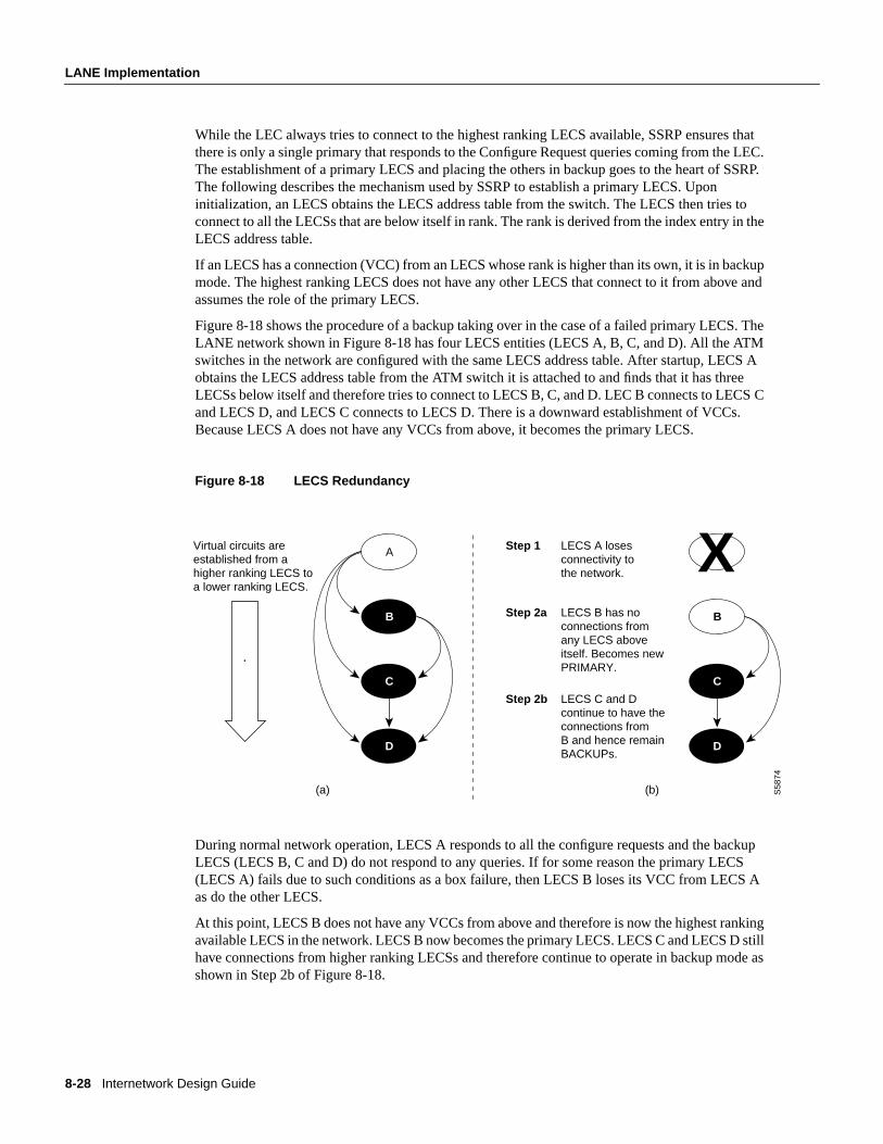
Figure 8-18 shows the procedure of a backup taking over in the case of a failed primary LECS. TheLANE network shown in Figure 8-18 has four LECS entities (LECS A, B, C, and D). All the ATMswitches in the network are configured with the same LECS address table. After startup, LECS Aobtains the LECS address table from the ATM switch it is attached to and finds that it has threeLECSs below itself and therefore tries to connect to LECS B, C, and D. LEC B connects to LECS Cand LECS D, and LECS C connects to LECS D. There is a downward establishment of VCCs.Because LECS A does not have any VCCs from above, it becomes the primary LECS.
Figure 8-18 LECS Redundancy
During normal network operation, LECS A responds to all the configure requests and the backupLECS (LECS B, C and D) do not respond to any queries. If for some reason the primary LECS(LECS A) fails due to such conditions as a box failure, then LECS B loses its VCC from LECS Aas do the other LECS.
At this point, LECS B does not have any VCCs from above and therefore is now the highest rankingavailable LECS in the network. LECS B now becomes the primary LECS. LECS C and LECS D stillhave connections from higher ranking LECSs and therefore continue to operate in backup mode asshown in Step 2b of Figure 8-18.
B
C
D
AVirtual circuits areestablished from ahigher ranking LECS to a lower ranking LECS.
C
D
AXLECS A losesconnectivity tothe network.
Step 1
LECS B has no connections from any LECS above itself. Becomes new PRIMARY.
Step 2a
LECS C and Dcontinue to have theconnections from B and hence remainBACKUPs.
Step 2b
(a) (b) S58
74
B
Designing ATM Internetworks 8-29
LANE Implementation
LES/BUS RedundancyThe LES/BUS redundancy portion of SSRP supports the configuration of multiple LES/BUS pairsthat work in a primary-secondary fashion. However, the mechanisms used here are different fromthose used for the LECS redundancy described in the preceding section.
Multiple LES/BUS pairs for a given ELAN are first configured into the LECS database. Within thisdatabase, each LES/BUS pair is assigned a priority. After initialization, each LES/BUS opens a VCCwith the primary LECS using the LECS address discovery mechanism. The LES/BUS pair with thehighest priority that has an open VCC to the LECS is assigned as the primary LES/BUS by theprimary LECS.
SSRP Usage GuidelinesThere are no theoretical limits on the number of LECSs that can be configured using SSRP, howevera recommended number is two (one primary plus one backup) or three LECSs (one primary plus twobackups). Any more redundancy should be implemented only after very careful considerationbecause it will add a significant amount of complexity to the network. This added complexity canresult in a substantial increase in the amount of time required to manage and troubleshoot suchnetworks.
SSRP Configuration GuidelinesTo support the LECS redundancy scheme you must adhere to the following configuration rules.Failure to do so will result in improper operation of SSRP and a malfunctioning network.
• Each LECS must maintain the same database of ELANs. Therefore, you must maintain the sameELAN database across all the LECSs.
• You must configure the LECS addresses in the LECS address table in the same order on eachATM switch in the network.
• When using SSRP with the Well Known Address, do not place two LECSs on the same ATMswitch. If you place two LECs on the same ATM switch, only one LECS can register the WellKnown Address with the ATM switch (through ILMI) and this can cause problems duringinitialization.
SSRP Interoperability NotesSSRP can be used with independent third-party LECs if they use ILMI for LECS address discoveryand can appropriately handle multiple LECS addresses returned by the ATM switch. For example,the LEC should step through connecting to the list of LECS addresses returned by the ATM switch.The first LECS that responds to the configuration request is the master LECS.
Behavior of SSRP with the Well Known LECS AddressSSRP also works with LECS Well Known Address (47.0079….) defined in the LANE 1.0specification. The Cisco LECS can listen on multiple ATM addresses at the same time. Therefore, itcan listen on the Well Known Address and the auto-configured ATM address, which can bedisplayed using theshow lane defaultcommand.
When the LECS is enabled to listen on the Well Known Address, it registers the Well KnownAddress with the ATM switch so that the ATM switches can advertise routes to the Well KnownAddress and route any call setups requests to the correct place.
8-30 Internetwork Design Guide
LANE Implementation
Under SSRP, there are multiple LECSs in the network. If each LECS registers the Well KnownAddress to the ATM switches that it is connected to, then call setups are routed to different places inthe network. Consequently, under SSRP you must configure an autoconfigured address so that thenegotiation of the master first takes place and then the master registers the Well Known Address withthe ATM switch. If the master fails, the Well Known Address moves with the master LECS. ThePNNI code on the LightStream 1010 switch takes care of advertising the new route to the WellKnown Address when there is a change of LECS mastership. Therefore, third-party LECs that useonly the Well Known Address can also interoperate with SSRP. SSRP is the only redundancy schemethat can be used with almost any LEC in the industry.
To implement SSRP with the Well Known Address, use the following steps:
1 Configure the LECS to listen on the autoconfigured address (or if you want a separate ATMaddress that you have predetermined). This auto-configured (or other) address should beprogrammed into the ATM switches for the LECS address discovery mechanism.
2 Configure each LECS to listen on the Well Known address using thelane configfixed-config-atm-address command. After the master LECS is determined using the LECSredundancy procedure, the master registers the Well Known Address to the ATM switch.
Note SSRP with the Well Known Address does not work properly under certain circumstances(during failover) if two LECS are attached to the same ATM switch. This is due to the possibility ofduplicate address registration on the same switch, which ILMI does not allow. Make sure each LECSis on a separate ATM switch.
Behavior of SSRP in Network PartitionsIn the event of network partitions where two separate ATM clouds are formed due to aninterconnecting link or switch failure, each cloud has its own set of LANE services if SSRP isconfigured to handle network partitions.
When configuring SSRP, use the following guidelines to accommodate the possibility of networkpartition:
• Configure each partition with its own LANE services that can become active during a networkpartition. For example, if you are connecting two sites or campuses across a MAN and you wantthe same ELANs at both locations, then configure each campus/site with its own LANE services.
• Routing behavior should be carefully examined during a network partition in the case where anELAN maps to a Layer 3 network (for example, an IP subnet or IPX network) because there arenow two routes to the same subnet (assuming there are redundant routers in the network). If thereare no redundant routers, then one of the partitions will be effectively isolated from the rest of thenetwork. Intra-ELAN traffic will continue to behave properly.
HSRP over LANEHSRP is a protocol that network designers can use to guard against router failures in the network.The HSRP protocol is exchanged between two routers and one of them is elected as the primaryrouter interface (or subinterface) for a given subnet. The other router acts as the “hot standby” router.
In HSRP, a default IP address and a default MAC address are shared between the two routersexchanging the HSRP protocol. This default IP address is used as the default gateway at all IP endstations for them to communicate with end stations outside their immediate subnet. Therefore, when
Designing ATM Internetworks 8-31
Role of Stratm Technology
there is a primary router failure, the hot standby router takes over the default gateway address andthe MAC address so that the end station can continue communicating with end stations that are notin their immediate subnet.
Because HSRP is a Layer 2 mechanism and needs a MAC address-based Layer 2 network, it ispossible to implement HSRP style recovery over LANE. The mechanisms used are the same as forany Ethernet interface and can be configured at a subinterface level.
Redundant ATM Port Card for the Catalyst 5000Another aspect of addressing the redundancy needs from a physical network perspective is theaddition of a redundant PHY portion of an ATM card. The Catalyst 5000 switch employs the dualPHY redundant ATM card. This redundancy is only at a physical level and is useful in cases wherethe primary link to the ATM switch goes down.
Role of Stratm TechnologyStratm Technology is a new approach to ATM switching technology that incorporates patentedstandards-based Cisco technology into custom silicon. These application-specific integrated circuits(ASICs) dramatically increase ATM efficiency and scalability and significantly lower the absolutecost of delivering ATM solutions. Stratm Technology can be implemented in switches and routersacross LANs, campus networks, and WANs, enabling the delivery of high-performance, end-to-endATM services to meet a wide range of needs.
Benefits of Stratm TechnologyThe benefits of Stratm Technology include the following:
• Dramatic improvement in network price/performance scalability
• Increased application “goodput”
• Protection of technology investments
• Increased portability
• Guaranteed infrastructure
Each of these benefits are described in more detail in the following sections.
Improved Network Price/Performance ScalabilityStratm Technology features can dramatically improve network price/performance and scalability asfollows:
• Support of up to eight OC-3 (155-Mbps) port interfaces per card slot, and up to 12 digital signalLevel 3 T3/E3 (45-Mbps) port interfaces per card slot
• A 30 percent increase in SVC completions to more than 4,000 per second per node
• An increase in connection density per switch by 500 percent
• An increase in the buffering capability of each card to 200,000 cells per card, upgradable tonearly one million cells
• A reduction in the price per port for high-speed connections by up to 50 percent
• The ability to support per-virtual-connection control queuing, rate scheduling, statisticscollection, and fair sharing of network resources on an individual connection basis
8-32 Internetwork Design Guide
Role of Stratm Technology
Increased Application “Goodput”Intelligent ATM features are embodied in Stratm Technology. These features are designed toincrease application “goodput” dramatically through advanced features, which are distributedthroughout the BXM module in silicon.
• Distributed ATM functions—Stratm distributes such ATM services as traffic management,per-VC queuing, class of service (COS) management, SVCs, and multicasting to each card on asilicon chip. Distributed functionality ensures faster, more efficient processing, and eliminatesthe possibility of a single point of failure disrupting the entire network.
• Highest bandwidth efficiency—Stratm delivers guaranteed bandwidth on demand, QOS, and fairsharing of network resources to each individual connection. With fast, efficient processing andguaranteed bandwidth, application performance is significantly enhanced.
• Advanced traffic management capabilities—Stratm incorporates the industry’s firstcommercially available Virtual Source/Virtual Destination (VS/VD) implementation of the fullATM Forum’s Traffic Management Specification Version 4.0. This ensures the highest efficiencyin bandwidth utilization and provides support for the multicasting capabilities required tosuccessfully deliver multimedia and switched internetworking services.
• End-to-end intelligence—With VS/VD implementation, Stratm also represents the industry’sfirst complete LAN-to-WAN ARB implementation. This feature enables ATM services to bedelivered to the desktop, ensuring high performance for the most demanding applications.
Industry-Leading Investment ProtectionStratm allows you to protect your current investments by integrating with today’s networkinfrastructures, and providing advanced features and functionality to protect investments far into thefuture. You can protect your technology investment because of the following Stratm capabilities:
• Seamlessly integrates with existing switches—Stratm Technology integrates into Cisco’s ATMswitching platforms, allowing you to enhance your investment in Cisco technology.
• Delivers unparalleled performance—Current ATM switching platforms deliver performancethat enables end-to-end delivery of high-quality, high-performance network services.
• Delivers the future—Stratm Technology extends the features and functionality of currentswitches to support next generation requirements. With this technology, you can easily delivermultiple services from a single network infrastructure and ensure the highest QOS possible.
Increases Portability and Guarantees an InfrastructureWith a modular chip set, Stratm increases the portability of standards-based ATM. ATM in siliconstabilizes the transport layer of networks, thereby guaranteeing the necessary infrastructure forefficient, high-performance delivery of emerging multimedia and Internet-based applications.
Designing ATM Internetworks 8-33
Cisco ATM WAN Products
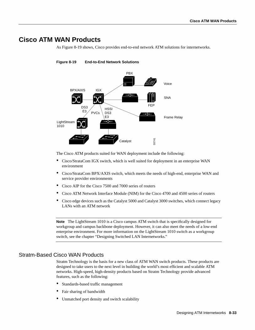
Cisco ATM WAN ProductsAs Figure 8-19 shows, Cisco provides end-to-end network ATM solutions for internetworks.
Figure 8-19 End-to-End Network Solutions
The Cisco ATM products suited for WAN deployment include the following:
• Cisco/StrataCom IGX switch, which is well suited for deployment in an enterprise WANenvironment
• Cisco/StrataCom BPX/AXIS switch, which meets the needs of high-end, enterprise WAN andservice provider environments
• Cisco AIP for the Cisco 7500 and 7000 series of routers
• Cisco ATM Network Interface Module (NIM) for the Cisco 4700 and 4500 series of routers
• Cisco edge devices such as the Catalyst 5000 and Catalyst 3000 switches, which connect legacyLANs with an ATM network
Note The LightStream 1010 is a Cisco campus ATM switch that is specifically designed forworkgroup and campus backbone deployment. However, it can also meet the needs of a low-endenterprise environment. For more information on the LightStream 1010 switch as a workgroupswitch, see the chapter “Designing Switched LAN Internetworks.”
Stratm-Based Cisco WAN ProductsStratm Technology is the basis for a new class of ATM WAN switch products. These products aredesigned to take users to the next level in building the world’s most efficient and scalable ATMnetworks. High-speed, high-density products based on Stratm Technology provide advancedfeatures, such as the following:
• Standards-based traffic management
• Fair sharing of bandwidth
• Unmatched port density and switch scalability
S57
41
BPX/AXIS IGX
DS3E3 PVCs
HSSIDS3E3
LightStream1010
Catalyst
PBX
FEP
SNA
Frame Relay
Voice
8-34 Internetwork Design Guide
Cisco ATM WAN Products
• High-performance SVCs
• Multicast capability
Cisco StrataCom BPXThe Cisco/StrataCom BPX Service Node is a standards-based, multiservice ATM switch designedto deliver the highest levels of network scalability, flexibility, and efficiency. The BPX achievesmultiservice functionality, efficient use of bandwidth, high performance for all users, and guaranteedQOS for all traffic types through its advanced traffic management features. These advanced trafficmanagement capabilities are based on the first fully compliant implementation of the ATM Forum’sTraffic Management Specification V. 4.0, as well as the International Telecommunications Union(ITU) Recommendations I.371 and I.35B.
The BPX incorporates Stratm Technology, which is implemented in custom silicon ASICs. Stratmdistributes advanced ATM capabilities throughout the switch modules, resulting in unmatched portdensity, support for hundreds of thousands of connections, and new functionality. Advanced trafficmanagement features, together with an optimized hardware architecture, enable the switch tosimultaneously support ATM, Frame Relay, Internet, voice, wireless communication, video,switched internetworking, and circuit emulation services.
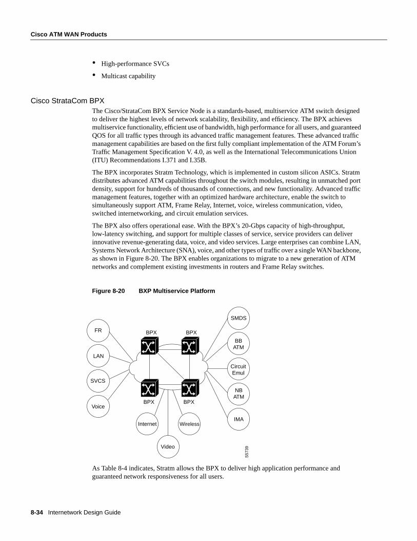
The BPX also offers operational ease. With the BPX’s 20-Gbps capacity of high-throughput,low-latency switching, and support for multiple classes of service, service providers can deliverinnovative revenue-generating data, voice, and video services. Large enterprises can combine LAN,Systems Network Architecture (SNA), voice, and other types of traffic over a single WAN backbone,as shown in Figure 8-20. The BPX enables organizations to migrate to a new generation of ATMnetworks and complement existing investments in routers and Frame Relay switches.
Figure 8-20 BXP Multiservice Platform
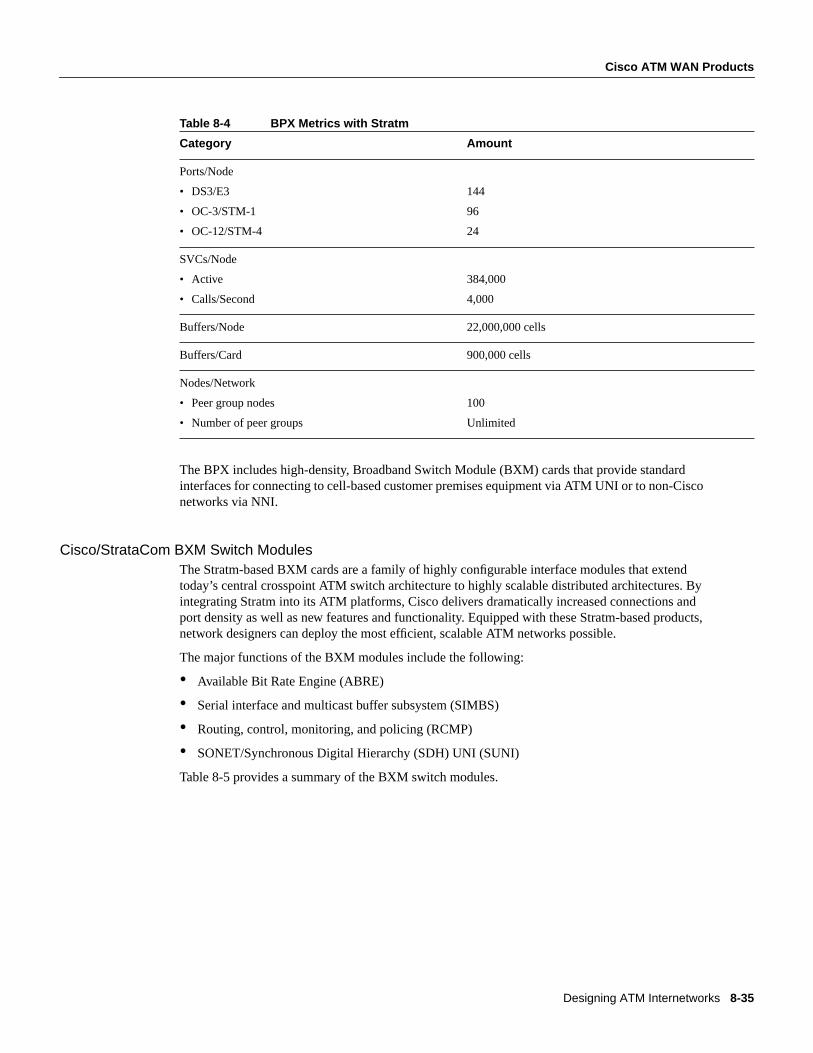
As Table 8-4 indicates, Stratm allows the BPX to deliver high application performance andguaranteed network responsiveness for all users.
SMDS
S57
39
BBATM
CircuitEmul
NBATM
IMA
FR
LAN
SVCS
VoiceBPXBPX
BPXBPX
Internet Wireless
Video
Designing ATM Internetworks 8-35
Cisco ATM WAN Products
Table 8-4 BPX Metrics with Stratm
The BPX includes high-density, Broadband Switch Module (BXM) cards that provide standardinterfaces for connecting to cell-based customer premises equipment via ATM UNI or to non-Cisconetworks via NNI.
Cisco/StrataCom BXM Switch ModulesThe Stratm-based BXM cards are a family of highly configurable interface modules that extendtoday’s central crosspoint ATM switch architecture to highly scalable distributed architectures. Byintegrating Stratm into its ATM platforms, Cisco delivers dramatically increased connections andport density as well as new features and functionality. Equipped with these Stratm-based products,network designers can deploy the most efficient, scalable ATM networks possible.
The major functions of the BXM modules include the following:
• Available Bit Rate Engine (ABRE)
• Serial interface and multicast buffer subsystem (SIMBS)
• Routing, control, monitoring, and policing (RCMP)
• SONET/Synchronous Digital Hierarchy (SDH) UNI (SUNI)
Table 8-5 provides a summary of the BXM switch modules.
Category Amount
Ports/Node
• DS3/E3
• OC-3/STM-1
• OC-12/STM-4
144
96
24
SVCs/Node
• Active
• Calls/Second
384,000
4,000
Buffers/Node 22,000,000 cells
Buffers/Card 900,000 cells
Nodes/Network
• Peer group nodes
• Number of peer groups
100
Unlimited
8-36 Internetwork Design Guide
Cisco ATM WAN Products
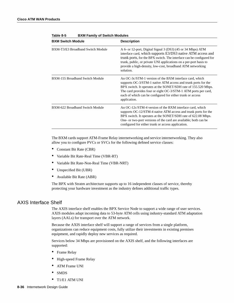
Table 8-5 BXM Family of Switch Modules
The BXM cards support ATM-Frame Relay internetworking and service internetworking. They alsoallow you to configure PVCs or SVCs for the following defined service classes:
• Constant Bit Rate (CBR)
• Variable Bit Rate-Real Time (VBR-RT)
• Variable Bit Rate-Non-Real Time (VBR-NRT)
• Unspecified Bit (UBR)
• Available Bit Rate (ABR)
The BPX with Stratm architecture supports up to 16 independent classes of service, therebyprotecting your hardware investment as the industry defines additional traffic types.
AXIS Interface ShelfThe AXIS interface shelf enables the BPX Service Node to support a wide range of user services.AXIS modules adapt incoming data to 53-byte ATM cells using industry-standard ATM adaptationlayers (AALs) for transport over the ATM network.
Because the AXIS interface shelf will support a range of services from a single platform,organizations can reduce equipment costs, fully utilize their investments in existing premisesequipment, and rapidly deploy new services as required.
Services below 34 Mbps are provisioned on the AXIS shelf, and the following interfaces aresupported:
• Frame Relay
• High-speed Frame Relay
• ATM Frame UNI
• SMDS
• T1/E1 ATM UNI
BXM Switch Module Description
BXM-T3/E3 Broadband Switch Module A 6- or 12-port, Digital Signal 3 (DS3) (45 or 34 Mbps) ATMinterface card,which supports E3/DS3 native ATM access andtrunk ports, for the BPX switch. The interface can be configured fortrunk, public, or private UNI applications on a per-port basis toprovide a high-density, low-cost, broadband ATM networkingsolution.
BXM-155 Broadband Switch Module An OC-3c/STM-1 version of the BXM interface card, whichsupports OC-3/STM-1 native ATM access and trunk ports for theBPX switch. It operates at the SONET/SDH rate of 155.520 Mbps.The card provides four or eight OC-3/STM-1 ATM ports per card,each of which can be configured for either trunk or accessapplication.
BXM-622 Broadband Switch Module An OC-12c/STM-4 version of the BXM interface card, whichsupports OC-12/STM-4 native ATM access and trunk ports for theBPX switch. It operates at the SONET/SDH rate of 622.08 Mbps.One- or two-port versions of the card are available; both can beconfigured for either trunk or access application.
Designing ATM Internetworks 8-37
Cisco ATM WAN Products
• n x T1/E1 inverse multiplexing for ATM (IMATM) UNI
• Circuit emulation
• ISDN switched access
Each AXIS shelf aggregates traffic from as many as 80 T1 or E1 ports onto a single port of themultiport broadband interface card. This high-port density maximizes use of the BPX high-capacityswitch fabric. A compact footprint minimizes the space required within central offices. Each 9-inch,rack-mounted shelf supports more than two thousand 64-kbps users.
Cisco/StrataCom IGX Family of SwitchesFor wide-area networking, LAN data flowing between different enterprise sites is aggregated by therouter and then mixed with voice and other legacy data streams across the corporate wide-areabackbone. Traditionally, these corporate backbones use TDM technology. However, as the use ofLAN data has exploded and older TDM equipment has been fully depreciated, newer solutions canbe cost justified. Enterprises are increasingly turning to a new public service officers (for example,VPN, Frame Relay, and Intranets) and a new generation of Frame Relay/ATM-based enterpriseswitches to maximize the efficient and minimize the cost of their networks.
The Cisco/StrataCom IGX family of switches provides the needed linkage to integrate thehigh-speed LAN data and the lower-speed voice and legacy data across the enterprise backbone inthe most cost-effective manner. The IGX family of switches is specifically designed for enterpriseintegration.
The IGX family of ATM enterprise WAN switches includes the IGX8 (8-slot switch), the IGX16(16-slot switch), and IGX32 (32-slot switch). The IGX family can provide the following enterpriseWAN support:
• Voice—UVM and CVM
• Legacy data—HDM and LDM
• ATM—ALM
• Frame Relay—UFM and FRM
• Trunks—NTM, BTM, and ALM
Benefits of the IGXWith the IGX switch, you can leverage ATM to save costs as follows:
• Apply utilization rates in your network design to source PVCs
• Combine multiple networks into one multiservice network
• Optimize the transmission network with design tools
For example, you can use StrataView+, a network management tool, for network discovery. You canalso use the Configuration Extraction Tool (CET) to populate the design data set with existingfacilities. With such design tools, incremental network design is possible.
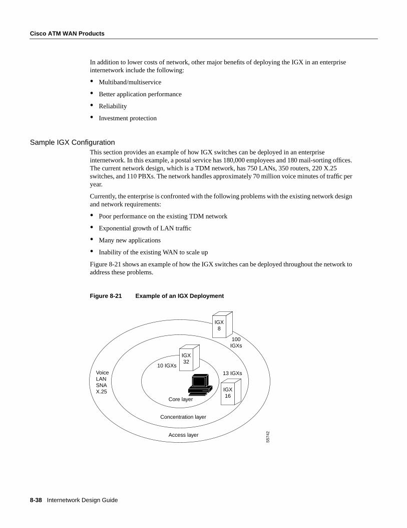
8-38 Internetwork Design Guide
Cisco ATM WAN Products
In addition to lower costs of network, other major benefits of deploying the IGX in an enterpriseinternetwork include the following:
• Multiband/multiservice
• Better application performance
• Reliability
• Investment protection
Sample IGX ConfigurationThis section provides an example of how IGX switches can be deployed in an enterpriseinternetwork. In this example, a postal service has 180,000 employees and 180 mail-sorting offices.The current network design, which is a TDM network, has 750 LANs, 350 routers, 220 X.25switches, and 110 PBXs. The network handles approximately 70 million voice minutes of traffic peryear.
Currently, the enterprise is confronted with the following problems with the existing network designand network requirements:
• Poor performance on the existing TDM network
• Exponential growth of LAN traffic
• Many new applications
• Inability of the existing WAN to scale up
Figure 8-21 shows an example of how the IGX switches can be deployed throughout the network toaddress these problems.
Figure 8-21 Example of an IGX Deployment
S57
42
10 IGXsVoice LANSNAX.25
13 IGXs
100IGXs
Core layer
Concentration layer
Access layer
IGX32
IGX8
IGX16
Designing ATM Internetworks 8-39
Cisco ATM WAN Products
By deploying the IGX switches throughout the enterprise internetwork, the following benefits areobtained:
• Integration of the voice and data networks
• Improved performance for each type of traffic
• Better response times for new applications
• Reduced downtime
• Higher bandwidth utilization (five-fold increase in traffic using existing trunks)
• Implementation of a scalable network that supports rapid deployment of new services
• Simplification of network design with a reduction in management costs
Cisco ATM LANE ProductsCisco offers a complete ATM LANE solution by providing the following:
• Inter-ATM ELAN communication through routing
• LEC/BUS/LECS/LES on Cisco 7500, 7000, 4500, and 4000 series routers
• LEC/BUS/LECS/LES on the Catalyst 5000 and Catalyst 3000 switches
• Cisco LightStream 1010 ATM switch
Cisco 7500 Router SeriesData center consolidation, client/server architectures using centralized servers, and growth in remotesites all drive the rapidly growing need for WAN bandwidth. High-performance routing providescritical functionality in the high-speed WAN environment.
The Cisco 7500 router series extends the capabilities of the Cisco 7000 family and incorporatesdistributed switching functions. The distributed switching capability allows network designers toprovide the high-performance routing necessary to support networks using ATM, multilayer LANswitching, and VLAN technologies.
The Cisco 7500 family of routers offers a broad support of high-speed ATM and WAN interfaces.The higher port densities supported the Cisco 7500 series easily handles the large number ofinterfaces that result from more remote site connectivity. The Cisco IOS software adaptive reroutingincreases network availability, and its flexible interfaces provide support for multiple services and amigration path to ATM. Network designers can deploy the Cisco 7500 series in the WANenvironment to access multiple types of carrier service offerings as they migrate from TDMbackbones to ATM backbones. The Cisco 7500 series also provides network security and minimizesthe loss of transparency. The Cisco 7500 series running Cisco IOS Software Release 11.0 or laterprovides tools for network configuration, fault detection, and minimizing unnecessary traffic acrossexpensive wide-area links.
Note The features discussed for the Cisco 7000 series are also applicable to the Cisco 7500 series.

8-40 Internetwork Design Guide
Cisco ATM WAN Products
Cisco 7000 SeriesThe ATM Interface Processor (AIP) card supports native ATM in Cisco 7000 and Cisco 7010 routersrunning Cisco IOS Software Release 10.0 or later. Supporting both AAL3/4 and AAL5, the ATMinterface processor enables high-speed communications between Cisco 7000 family routers andstandards-based ATM networks. Cisco IOS Software Release 11.0 and later support LANE.
Note Cisco IOS Software Release 10.0 supports AAL5 PVCs only.
Cisco IOS Software Release 10.0 and later support ATM Forum UNI Specification V3.0, whichincludes the user-to-network ATM signaling specification. The AIP card uses RFC 1483(Multiprotocol Encapsulation over AAL5) to transport data through an ATM network. RFC 1483specifies the use of an LLC/SNAP 8-byte header to identify the encapsulated protocol. It alsospecifies a null encapsulation (VC Mux) which, instead of headers, creates a separate virtual circuitper protocol.
The AIP supports the following protocols:
• AppleTalk
• Banyan Virtual Network System (VINES)
• Connectionless Network Service (CLNS)
• DECnet
• IP
• Novell Internetwork Packet Exchange (IPX)
The following physical layer interface modules (PLIMs) are available for the AIP:
• TAXI 4B/5B 100-megabits-per-second (Mbps) multimode fiber-optic cable
• SONET/SDH 155-Mbps multimode fiber-optic (STS-3c or STM1) cable
• SONET/SDH 155-Mbps single mode fiber-optic (STS-3c or STM1) cable
• E3 34-Mbps coaxial cable
• DS-3 45-Mbps cable
The total bandwidth though all the AIPs configured in a router should be limited to 200 Mbps fullduplex. For that reason, only the following combinations are supported:
• Two TAXI interfaces
• One SONET and one E3 interface
• Two SONET interfaces, one of which is lightly used
• Five E3 interfaces
The AIP includes hardware support for various traffic shaping functions. Virtual circuits can beassigned to one of eight rate queues, each of which is programmable for a different peak rate. Eachvirtual circuit can be assigned an average rate and specific burst size. The signaling request specifiesthe size of the burst that will be sent at the peak rate, and after that burst, the rest of the data will besent at the average rate.
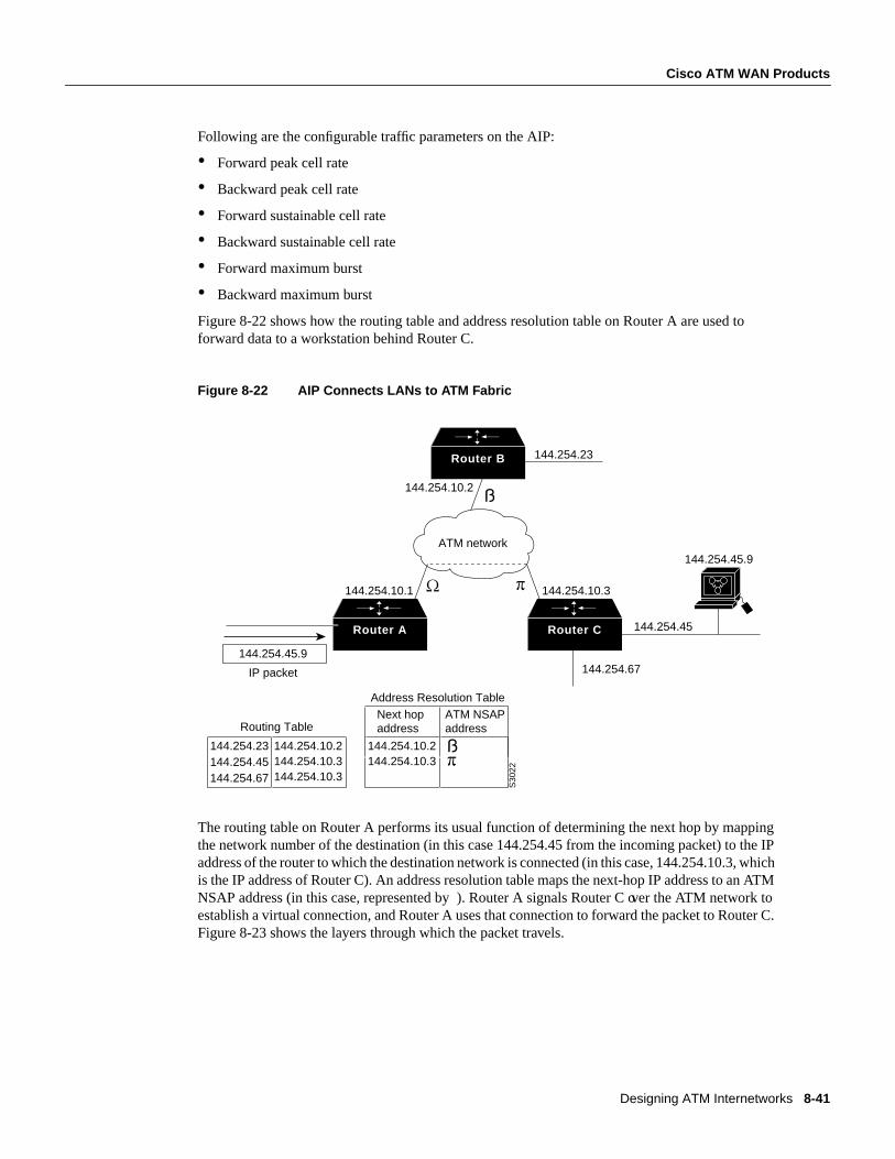
Designing ATM Internetworks 8-41
Cisco ATM WAN Products
Following are the configurable traffic parameters on the AIP:
• Forward peak cell rate
• Backward peak cell rate
• Forward sustainable cell rate
• Backward sustainable cell rate
• Forward maximum burst
• Backward maximum burst
Figure 8-22 shows how the routing table and address resolution table on Router A are used toforward data to a workstation behind Router C.
Figure 8-22 AIP Connects LANs to ATM Fabric
The routing table on Router A performs its usual function of determining the next hop by mappingthe network number of the destination (in this case 144.254.45 from the incoming packet) to the IPaddress of the router to which the destination network is connected (in this case, 144.254.10.3, whichis the IP address of Router C). An address resolution table maps the next-hop IP address to an ATMNSAP address (in this case, represented by ). Router A signals Router C over the ATM network toestablish a virtual connection, and Router A uses that connection to forward the packet to Router C.Figure 8-23 shows the layers through which the packet travels.
Router B
Router A Router C
144.254.45.9
IP packet
144.254.10.1
ATM network
144.254.10.3
144.254.10.2
144.254.23
144.254.45.9
144.254.67
Routing Table
144.254.23144.254.45144.254.67
144.254.10.2144.254.10.3144.254.10.3
Address Resolution Table
144.254.10.2144.254.10.3
144.254.45
S30
22
Next hopaddress
ATM NSAPaddress
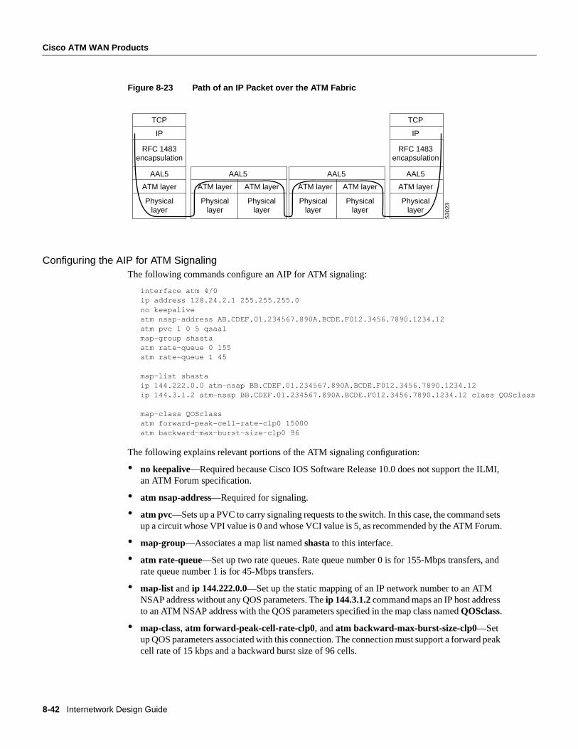
8-42 Internetwork Design Guide
Cisco ATM WAN Products
Figure 8-23 Path of an IP Packet over the ATM Fabric
Configuring the AIP for ATM SignalingThe following commands configure an AIP for ATM signaling:
interface atm 4/0ip address 128.24.2.1 255.255.255.0no keepaliveatm nsap-address AB.CDEF.01.234567.890A.BCDE.F012.3456.7890.1234.12atm pvc 1 0 5 qsaalmap-group shastaatm rate-queue 0 155atm rate-queue 1 45
map-list shastaip 144.222.0.0 atm-nsap BB.CDEF.01.234567.890A.BCDE.F012.3456.7890.1234.12ip 144.3.1.2 atm-nsap BB.CDEF.01.234567.890A.BCDE.F012.3456.7890.1234.12 class QOSclass
map-class QOSclassatm forward-peak-cell-rate-clp0 15000atm backward-max-burst-size-clp0 96
The following explains relevant portions of the ATM signaling configuration:
• no keepalive—Required because Cisco IOS Software Release 10.0 does not support the ILMI,an ATM Forum specification.
• atm nsap-address—Required for signaling.
• atm pvc—Sets up a PVC to carry signaling requests to the switch. In this case, the command setsup a circuit whose VPI value is 0 and whose VCI value is 5, as recommended by the ATM Forum.
• map-group—Associates a map list namedshasta to this interface.
• atm rate-queue—Set up two rate queues. Rate queue number 0 is for 155-Mbps transfers, andrate queue number 1 is for 45-Mbps transfers.
• map-list andip 144.222.0.0—Set up the static mapping of an IP network number to an ATMNSAP address without any QOS parameters. Theip 144.3.1.2 command maps an IP host addressto an ATM NSAP address with the QOS parameters specified in the map class namedQOSclass.
• map-class, atm forward-peak-cell-rate-clp0, andatm backward-max-burst-size-clp0—Setup QOS parameters associated with this connection. The connection must support a forward peakcell rate of 15 kbps and a backward burst size of 96 cells.
TCP
IP
RFC 1483encapsulation
AAL5
ATM layer
Physicallayer
AAL5
ATM layer
Physicallayer
ATM layer
Physicallayer
TCP
IP
RFC 1483encapsulation
AAL5
ATM layer
Physicallayer
S30
23
AAL5
ATM layer
Physicallayer
ATM layer
Physicallayer
Designing ATM Internetworks 8-43
Cisco ATM WAN Products
Interoperability with DXIWhen configuring an AIP to communicate with a Cisco router that uses ATM DXI to connect to theATM network, the AIP requires Network Layer Protocol Identifier (NLPID) encapsulation, which isprovided in Cisco IOS Software Release 10.2, or the ATM DXI requires LLC/SNAP encapsulation.
Cisco 4500/4700 ATM NIMThe NIM is the mid-range ATM router interface for the Cisco 4500 and Cisco 4700 series of routers.The function of this ATM module is internally much different than that of the AIP module. With theCisco 4500 and 4700 series router, the packet memory is kept in a 4-Mbps pool that is shared by allof the NIMs. The Cisco IOS software also runs on these routers so the same ATM functionality andcommands work on both the Cisco AIP and NIM. The performance of the NIM is actually better inthe NIM for process and fast-switched protocols, but the Autonomous/SSE switching available inthe Cisco 7000 series, and fast switching available on the Cisco 7500 series remain the fastest in theproduct family.
In this regard, network designers can deploy the Cisco 4700 series of routers to offer LANE servicesbecause the BUS is in the fast switching path. It is important to note that the NIM supports1024 VCCs and this should be taken into consideration in SVC-intensive LANE networks.
ATM Edge DevicesThe Catalyst 5000 and Catalyst 3000 switches are LAN switches that have ATM uplinks.Consequently, network designers can use these switches as edge devices to interconnect legacyLANs to an ATM network.
Catalyst 5000 as an ATM Edge DeviceThe Catalyst 5000 ATM LANE Dual PHY modules integrates high-speed, switched LANs across anATM campus network providing legacy LANs with access to ATM-based services in the backbone.The ATM module supports two (one primary and one secondary) 155-Mbps OC-3c interfaces witha wide range of media options (for example, single-mode fiber, multimode fiber, and unshieldedtwisted pair [UTP Category 5]).
A maximum of three ATM LANE modules can be supported simultaneously in one Catalyst 5000switch to provide redundant, fault-tolerant connections. This module delivers redundant LANEservices through Cisco’s LANE SSRP.
The Catalyst 5000 ATM module is designed to provide Ethernet to ATM functionality by acting asa LANE client. The BUS functionality on the Catalyst 5000 ATM card was designed for very highperformance. The data path for the BUS is implemented entirely in firmware/hardware.
Catalyst 3000 as an ATM Edge DeviceThe Catalyst 3000 switch can also function as an ATM LANE edge device. Like the Catalyst 5000switch, the Catalyst 3000 switch also supports an ATM LANE module. The Catalyst 3000 ATMmodule supports a 155-Mpbs OC-3c multimode optical interface that is compliant with the ATMForum UNI 3.0 and UNI 3.1 specifications. The ATM module in conjunction with otherCatalyst 3000 modules can also be used to connect Fast Ethernet hubs, switches, and routers to theATM backbone.

8-44 Internetwork Design Guide
Cisco ATM WAN Products
Support for Cisco’s VLAN Trunking Protocol (VTP) allows multiple Catalyst 3000 and Catalyst5000 switches within a network to share ELAN or VLAN configuration information. For example,VTP will automatically map VLANs based upon Fast Ethernet trunks (ISL) to ELANs based uponATM trunks.
LightStream 1010 ATM SwitchesThe LightStream 1010 family of switches are modular switches designed for campuses orworkgroups depending upon the types of interfaces used. Its central processor is dedicated to asingle, field replaceable ATM Switch/Processor module (ASP).
Single-Switch DesignsBecause ATM can use existing multimode fiber networks, FDDI campus backbones can be easilyupgraded from 100-Mbps FDDI to 155-Mbps point-to-point ATM. If the network has spare fiber,AIPs can be installed in each router and interconnected with a LightStream 1010 switch, as shownin Figure 8-24. In this topology, each router has a 155-Mbps point-to-point connection to every otherrouter on the ring.
Figure 8-24 Parallel FDDI and ATM Backbone
The addition of the ATM switch creates a parallel subnet. During the migration to ATM, a routingprotocol, such as the Interior Gateway Routing Protocol (IGRP), can be used to force FDDI routing,as shown by the following commands:
interface fddi 1/0ip address 4.4.4.1 255.255.255.0interface atm 2/0ip address 4.4.5.1 255.255.255.0router igrp 109network 4.4.0.0distance 150 4.4.5.0 0.0.0.255
Thedistance command causes ATM to appear as a less desirable network and forces routing overFDDI.
If the network does not have spare fiber, a concentrator can be installed. Later, an ATM switch canbe installed, as shown in Figure 8-25, which can be used to migrate ATM slowly throughout thenetwork, using FDDI as a backup.
Router Router
Router Router
S30
25
FDDI 4.4.4.0
ATM4.4.5.0
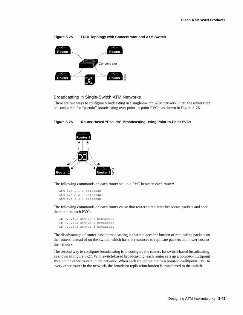
Designing ATM Internetworks 8-45
Cisco ATM WAN Products
Figure 8-25 FDDI Topology with Concentrator and ATM Switch
Broadcasting in Single-Switch ATM NetworksThere are two ways to configure broadcasting in a single-switch ATM network. First, the routers canbe configured for “pseudo” broadcasting over point-to-point PVCs, as shown in Figure 8-26.
Figure 8-26 Router-Based “Pseudo” Broadcasting Using Point-to-Point PVCs
The following commands on each router set up a PVC between each router:
atm pvc 1 1 1 aal5snapatm pvc 2 2 1 aal5snapatm pvc 3 3 1 aal5snap
The following commands on each router cause that router to replicate broadcast packets and sendthem out on each PVC:
ip 4.4.5.1 atm-vc 1 broadcastip 4.4.5.2 atm-vc 2 broadcastip 4.4.5.3 atm-vc 3 broadcast
The disadvantage of router-based broadcasting is that it places the burden of replicating packets onthe routers instead of on the switch, which has the resources to replicate packets at a lower cost tothe network.
The second way to configure broadcasting is to configure the routers for switch-based broadcasting,as shown in Figure 8-27. With switch-based broadcasting, each router sets up a point-to-multipointPVC to the other routers in the network. When each router maintains a point-to-multipoint PVC toevery other router in the network, the broadcast replication burden is transferred to the switch.
Router Router
Router Router
S30
32
Concentrator
Router 1 Router 3
Router 2
S30
34
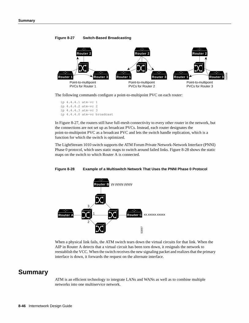
8-46 Internetwork Design Guide
Summary
Figure 8-27 Switch-Based Broadcasting
The following commands configure a point-to-multipoint PVC on each router:
ip 4.4.4.1 atm-vc 1ip 4.4.4.2 atm-vc 2ip 4.4.4.3 atm-vc 3ip 4.4.4.0 atm-vc broadcast
In Figure 8-27, the routers still have full-mesh connectivity to every other router in the network, butthe connections are not set up as broadcast PVCs. Instead, each router designates thepoint-to-multipoint PVC as a broadcast PVC and lets the switch handle replication, which is afunction for which the switch is optimized.
The LightStream 1010 switch supports the ATM Forum Private Network-Network Interface (PNNI)Phase 0 protocol, which uses static maps to switch around failed links. Figure 8-28 shows the staticmaps on the switch to which Router A is connected.
Figure 8-28 Example of a Multiswitch Network That Uses the PNNI Phase 0 Protocol
When a physical link fails, the ATM switch tears down the virtual circuits for that link. When theAIP in Router A detects that a virtual circuit has been torn down, it resignals the network toreestablish the VCC. When the switch receives the new signaling packet and realizes that the primaryinterface is down, it forwards the request on the alternate interface.
SummaryATM is an efficient technology to integrate LANs and WANs as well as to combine multiplenetworks into one multiservice network.
Router 2
Router 1 Router 3
Router 2
Router 1 Router 3
Router 2
Router 1 Router 3
S30
56
Point-to-multipointPVCs for Router 2
Point-to-multipointPVCs for Router 1
Point-to-multipointPVCs for Router 3
Router B
Router A Router C
yy.yyyyy.yyyyy
xx.xxxxx.xxxxx
3
2
1
S30
57