Embed Size (px)
Citation preview

Roof Construction Techniques: Pro’s and Con’s . . . . . . . . . . . . . . . . . . . . . . . . . . . . . . . . . . . . . . . . . . . . . 2
Trusses: Special Benefits for Architects and Engineers . . . . . . . . . . . . . . . . . . . . . . . . . . . . . . . . . . . . . . . 4
Special Benefits for Contractors and Builders . . . . . . . . . . . . . . . . . . . . . . . . . . . . . . . . . . . . . . . . . . . . . . . 5
Special Benefits for the Owner . . . . . . . . . . . . . . . . . . . . . . . . . . . . . . . . . . . . . . . . . . . . . . . . . . . . . . . . . . . 5
How Does A Truss Work? . . . . . . . . . . . . . . . . . . . . . . . . . . . . . . . . . . . . . . . . . . . . . . . . . . . . . . . . . . . . . . . 6
Typical Framing Systems. . . . . . . . . . . . . . . . . . . . . . . . . . . . . . . . . . . . . . . . . . . . . . . . . . . . . . . . . . . . . . . . 8
Gable Framing Variations . . . . . . . . . . . . . . . . . . . . . . . . . . . . . . . . . . . . . . . . . . . . . . . . . . . . . . . . . . . . . . 11
Hip Set Framing Variations . . . . . . . . . . . . . . . . . . . . . . . . . . . . . . . . . . . . . . . . . . . . . . . . . . . . . . . . . . . . . 13
Additional Truss Framing OptionsValley Sets . . . . . . . . . . . . . . . . . . . . . . . . . . . . . . . . . . . . . . . . . . . . . . . . . . . . . . . . . . . . . . . . . . . 15Piggyback Trusses . . . . . . . . . . . . . . . . . . . . . . . . . . . . . . . . . . . . . . . . . . . . . . . . . . . . . . . . . . . . . 17
Typical Truss Configurations . . . . . . . . . . . . . . . . . . . . . . . . . . . . . . . . . . . . . . . . . . . . . . . . . . . . . . . . . . . . 18
Typical Truss Shapes. . . . . . . . . . . . . . . . . . . . . . . . . . . . . . . . . . . . . . . . . . . . . . . . . . . . . . . . . . . . . . . . . . 20
Typical Bearing / Heel ConditionsExterior Bearing Conditions. . . . . . . . . . . . . . . . . . . . . . . . . . . . . . . . . . . . . . . . . . . . . . . . . . . . . . 21Crushing at the Heel . . . . . . . . . . . . . . . . . . . . . . . . . . . . . . . . . . . . . . . . . . . . . . . . . . . . . . . . . . . 22Trusses Sitting on Concrete Walls . . . . . . . . . . . . . . . . . . . . . . . . . . . . . . . . . . . . . . . . . . . . . . . . . 22Top Chord Bearing. . . . . . . . . . . . . . . . . . . . . . . . . . . . . . . . . . . . . . . . . . . . . . . . . . . . . . . . . . . . . 23Mid-Height Bearing . . . . . . . . . . . . . . . . . . . . . . . . . . . . . . . . . . . . . . . . . . . . . . . . . . . . . . . . . . . . 23Leg-Thru to the Bearing. . . . . . . . . . . . . . . . . . . . . . . . . . . . . . . . . . . . . . . . . . . . . . . . . . . . . . . . . 23Tail Bearing Tray. . . . . . . . . . . . . . . . . . . . . . . . . . . . . . . . . . . . . . . . . . . . . . . . . . . . . . . . . . . . . . . 24Interior Bearing Conditions . . . . . . . . . . . . . . . . . . . . . . . . . . . . . . . . . . . . . . . . . . . . . . . . . . . . . . 24Typical Heel Conditions. . . . . . . . . . . . . . . . . . . . . . . . . . . . . . . . . . . . . . . . . . . . . . . . . . . . . . . . . 25
Optional End CosmeticsLevel Return. . . . . . . . . . . . . . . . . . . . . . . . . . . . . . . . . . . . . . . . . . . . . . . . . . . . . . . . . . . . . 25Nailer . . . . . . . . . . . . . . . . . . . . . . . . . . . . . . . . . . . . . . . . . . . . . . . . . . . . . . . . . . . . . . . . . . 25Parapet . . . . . . . . . . . . . . . . . . . . . . . . . . . . . . . . . . . . . . . . . . . . . . . . . . . . . . . . . . . . . . . . . 26Mansard . . . . . . . . . . . . . . . . . . . . . . . . . . . . . . . . . . . . . . . . . . . . . . . . . . . . . . . . . . . . . . . . 26Cantilever . . . . . . . . . . . . . . . . . . . . . . . . . . . . . . . . . . . . . . . . . . . . . . . . . . . . . . . . . . . . . . . 26Stub . . . . . . . . . . . . . . . . . . . . . . . . . . . . . . . . . . . . . . . . . . . . . . . . . . . . . . . . . . . . . . . . . . . 26
Bracing Examples . . . . . . . . . . . . . . . . . . . . . . . . . . . . . . . . . . . . . . . . . . . . . . . . . . . . . . . . . . . . . . . . . . . . 27
Erection of Trusses . . . . . . . . . . . . . . . . . . . . . . . . . . . . . . . . . . . . . . . . . . . . . . . . . . . . . . . . . . . . . . . . . . . 29
Temporary Bracing . . . . . . . . . . . . . . . . . . . . . . . . . . . . . . . . . . . . . . . . . . . . . . . . . . . . . . . . . . . . . . . . . . . 30
Checklist for Truss Bracing Design Estimates . . . . . . . . . . . . . . . . . . . . . . . . . . . . . . . . . . . . . . . . . . . . . . 32
Floor Systems . . . . . . . . . . . . . . . . . . . . . . . . . . . . . . . . . . . . . . . . . . . . . . . . . . . . . . . . . . . . . . . . . . . . . . . 33
Typical Bearing / Heel Conditions for Floor TrussesTop Chord, Bottom Chord, and Mid-Height Bearing. . . . . . . . . . . . . . . . . . . . . . . . . . . . . . . . . . . 34Interior Bearing Conditions . . . . . . . . . . . . . . . . . . . . . . . . . . . . . . . . . . . . . . . . . . . . . . . . . . . . . . 35Ribbon Boards, Strongbacks and Fire Cut Ends . . . . . . . . . . . . . . . . . . . . . . . . . . . . . . . . . . . . . . 36
Steel Trusses . . . . . . . . . . . . . . . . . . . . . . . . . . . . . . . . . . . . . . . . . . . . . . . . . . . . . . . . . . . . . . . . . . . . . . . 37
Ask Charlie V. . . . . . . . . . . . . . . . . . . . . . . . . . . . . . . . . . . . . . . . . . . . . . . . . . . . . . . . . . . . . . . . . . . . . . . 38
Charlie’s Advice on Situations to Watch Out for in the Field. . . . . . . . . . . . . . . . . . . . . . . . . . . . . . . . . . . 41
Glossary of Terms . . . . . . . . . . . . . . . . . . . . . . . . . . . . . . . . . . . . . . . . . . . . . . . . . . . . . . . . . . . . . . . . . . . . 42
Appendix - References . . . . . . . . . . . . . . . . . . . . . . . . . . . . . . . . . . . . . . . . . . . . . . . . . . . . . . . . . . . . . . . . 48
TTable of Contentsable of Contents
1
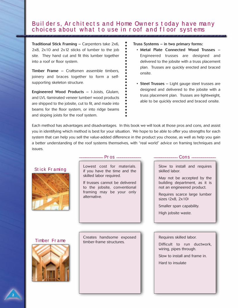
Traditional Stick Framing – Carpenters take 2x6,
2x8, 2x10 and 2x12 sticks of lumber to the job
site. They hand cut and fit this lumber together
into a roof or floor system.
Timber Frame – Craftsmen assemble timbers,
joinery and braces together to form a self-
supporting skeleton structure.
Engineered Wood Products – I-Joists, Glulam,
and LVL (laminated veneer lumber) wood products
are shipped to the jobsite, cut to fit, and made into
beams for the floor system, or into ridge beams
and sloping joists for the roof system.
Truss Systems – in two primary forms:
• Metal Plate Connected Wood Trusses –
Engineered trusses are designed and
delivered to the jobsite with a truss placement
plan. Trusses are quickly erected and braced
onsite.
• Steel Trusses – Light gauge steel trusses are
designed and delivered to the jobsite with a
truss placement plan. Trusses are lightweight,
able to be quickly erected and braced onsite.
Builders, ArBuilders, Architects and Home Owners today have manychitects and Home Owners today have manychoices about what to use in rchoices about what to use in roof and floor systemsoof and floor systems
2
Each method has advantages and disadvantages. In this book we will look at those pros and cons, and assist
you in identifying which method is best for your situation. We hope to be able to offer you strengths for each
system that can help you sell the value-added difference in the product you choose, as well as help you gain
a better understanding of the roof systems themselves, with “real world” advice on framing techniques and
issues.
________________ ________ PrPros os ________________________
Stick FramingStick Framing
TTimber Frameimber Frame
________________ ________ Cons Cons ________________________
Lowest cost for materials. if you have the time and theskilled labor required.
If trusses cannot be deliveredto the jobsite, conventionalframing may be your onlyalternative.
Slow to install and requiresskilled labor.
May not be accepted by thebuilding department, as it isnot an engineered product.
Requires scarce large lumbersizes (2x8, 2x10)
Smaller span capability.
High jobsite waste.
Creates handsome exposedtimber-frame structures.
Requires skilled labor.
Difficult to run ductwork,wiring, pipes through.
Slow to install and frame in.
Hard to insulate
3
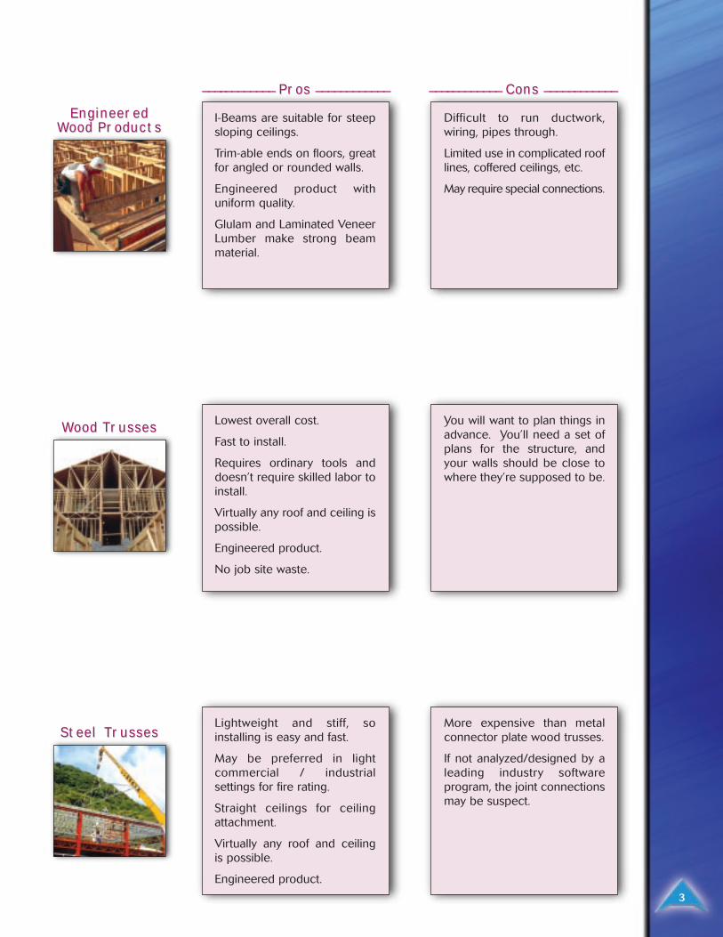
EngineerEngineerededWWood Prood Productsoducts
WWood Tood Trrussesusses
Steel TSteel Trrussesusses
________________ ________ PrPros os ________________________ ________________ ________ Cons Cons ________________________
I-Beams are suitable for steepsloping ceilings.
Trim-able ends on floors, greatfor angled or rounded walls.
Engineered product withuniform quality.
Glulam and Laminated VeneerLumber make strong beammaterial.
Difficult to run ductwork,wiring, pipes through.
Limited use in complicated rooflines, coffered ceilings, etc.
May require special connections.
Lowest overall cost.
Fast to install.
Requires ordinary tools anddoesn’t require skilled labor toinstall.
Virtually any roof and ceiling ispossible.
Engineered product.
No job site waste.
You will want to plan things inadvance. You’ll need a set ofplans for the structure, andyour walls should be close towhere they’re supposed to be.
Lightweight and stiff, soinstalling is easy and fast.
May be preferred in lightcommercial / industrialsettings for fire rating.
Straight ceilings for ceilingattachment.
Virtually any roof and ceiling is possible.
Engineered product.
More expensive than metalconnector plate wood trusses.
If not analyzed/designed by aleading industry softwareprogram, the joint connectionsmay be suspect.
Trusses bring virtually unlimited architectural
versatility, providing simple solutions to complex
designs and unusual conditions without inhibiting
building design freedom. Using trusses, you
have complete flexibility in interior room
arrangements, too. Using Alpine’s proprietary
VIEW software, truss designers can produce
engineered shapes that satisfy virtually any
aesthetic and functional specification by the
building design professional.
Trusses are an engineered and tested product.
There are nationally recognized standards for truss
design and manufacturing of metal plate
connected wood trusses. These standards have
been adopted by major model building codes.
This ensures a quality product. Alpine Professional
Engineers are committed to providing the highest
quality, cost efficient structural products for
your clients.
Trusses span longer than conventional framing,
so you have more open space to work with in
the interior.
Truss manufacturers using Alpine software are
available for consultation when special framing
situations arise.
Wood trusses connected with metal plates enjoy
an outstanding record of more than 35 years of
proven performance and durability.
State of the art truss design software allows
manufacturers to design them to be:
• Hurricane-resistant, and/or
• Withstand heavy snow loads, and/or
• Support storage areas above the ceiling.
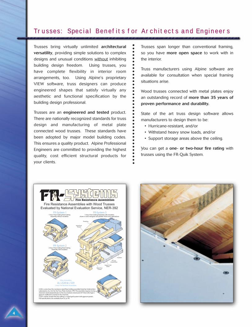
You can get a one- or two-hour fire rating with
trusses using the FR-Quik System.
TTrrusses: Special Benefits for Arusses: Special Benefits for Architects and Engineerschitects and Engineers
4
Trusses go up faster and easier, with less skilled
labor requirements, no matter how complicated
the roof or ceiling is.
Trusses put you under roof faster, which helps in
drawing construction loans.
The use of preassembled components generates
less waste at the jobsite. This improves safety
and reduces cleanup costs. On-site losses
from mis-cutting, theft and damage are
virtually eliminated.
Trusses are built in a computer-aided
manufacturing environment to assure accuracy
and quality.
Industry standards for manufacturing and handling
assure code-compliance. Building departments
recognize these standards and respect the
software used to design trusses. While many
building departments are wary about inspecting
conventional framing, sealed truss designs are
easily inspected.
Trusses are lightweight and easy to install,
requiring only normal construction tools.
The wide nailing surface of 4x2 floor trusses safely
speeds deck and flooring installation.
Expenses are accurately controlled because truss
costs can be predetermined.
Open web design allows easy installation of
plumbing, electrical wiring and heating/cooling
ductwork.
Trusses are available locally for fast delivery. More
than 550 truss manufacturers throughout the
United States and Canada are backed by the
expertise of Alpine Engineered Products, Inc.
The owner can enjoy peace of mind, knowing that
the trusses have been professionally engineered
and quality manufactured for the specific job.
The resiliency of wood provides a floor system that
is comfortable.
Wood is a natural insulator because it is composed
of thousands of individual cells, making it a poor
conductor of heat and cold.
Roof truss details such as tray, vaulted or studio
ceilings improve the appearance and comfort of
homes, offices, churches and commercial
buildings.
Floor trusses can conceal mechanical services,
leaving a clear plane for ceiling installations. This is
ideal for finished rooms in a lower level.
Trusses provide clear spans so interior walls can
be moved easily during remodeling or when
making additions. It is very economical to remodel
homes with trusses, versus frame houses.
Special Benefits for Contractors and BuildersSpecial Benefits for Contractors and Builders
Special Benefits for the OwnerSpecial Benefits for the Owner
5
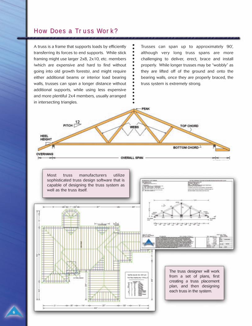
A truss is a frame that supports loads by efficiently
transferring its forces to end supports. While stick
framing might use larger 2x8, 2x10, etc. members
(which are expensive and hard to find without
going into old growth forests), and might require
either additional beams or interior load bearing
walls, trusses can span a longer distance without
additional supports, while using less expensive
and more plentiful 2x4 members, usually arranged
in intersecting triangles.
Trusses can span up to approximately 90’,
although very long truss spans are more
challenging to deliver, erect, brace and install
properly. While longer trusses may be “wobbly” as
they are lifted off of the ground and onto the
bearing walls, once they are properly braced, the
truss system is extremely strong.
How Does a THow Does a Trruss Wuss Work?ork?
6
Most truss manufacturers utilizesophisticated truss design software that iscapable of designing the truss system aswell as the truss itself.
The truss designer will workfrom a set of plans, firstcreating a truss placementplan, and then designingeach truss in the system.
7
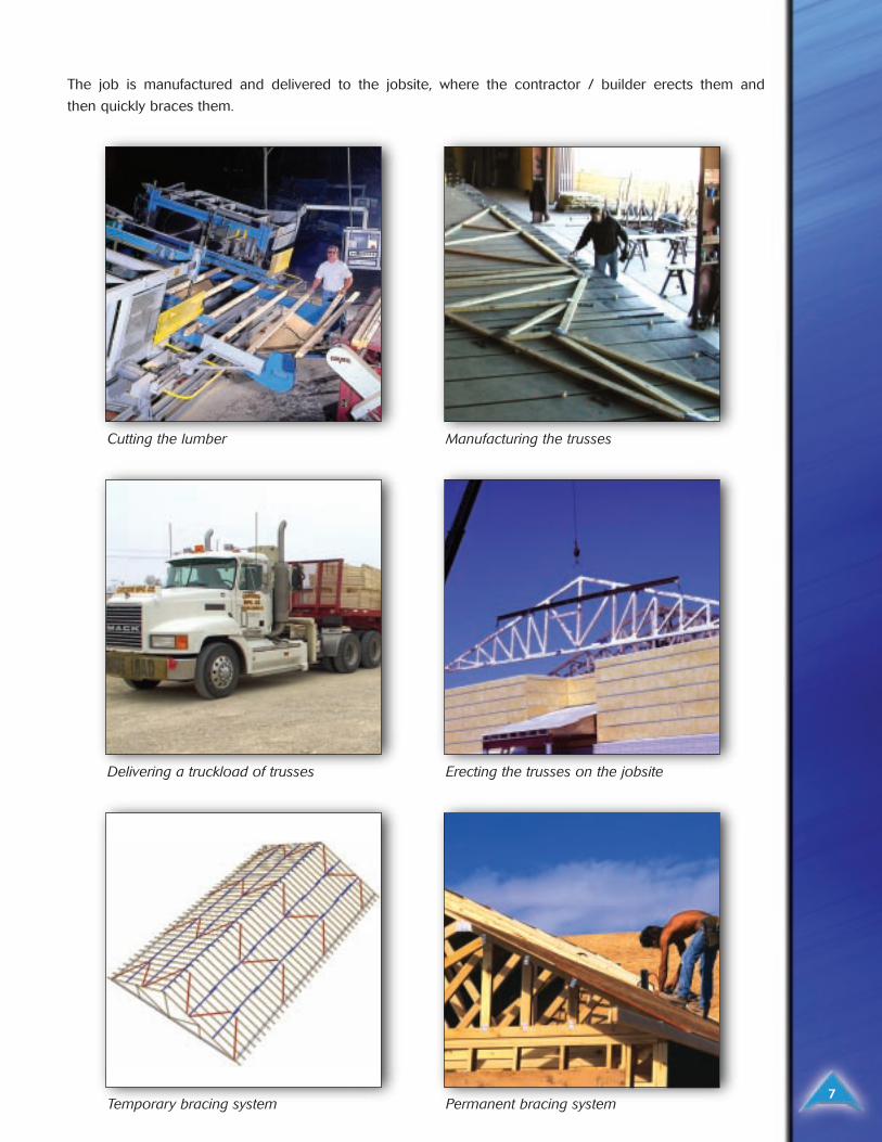
The job is manufactured and delivered to the jobsite, where the contractor / builder erects them and
then quickly braces them.
Cutting the lumber Manufacturing the trusses
Delivering a truckload of trusses Erecting the trusses on the jobsite
Temporary bracing system Permanent bracing system
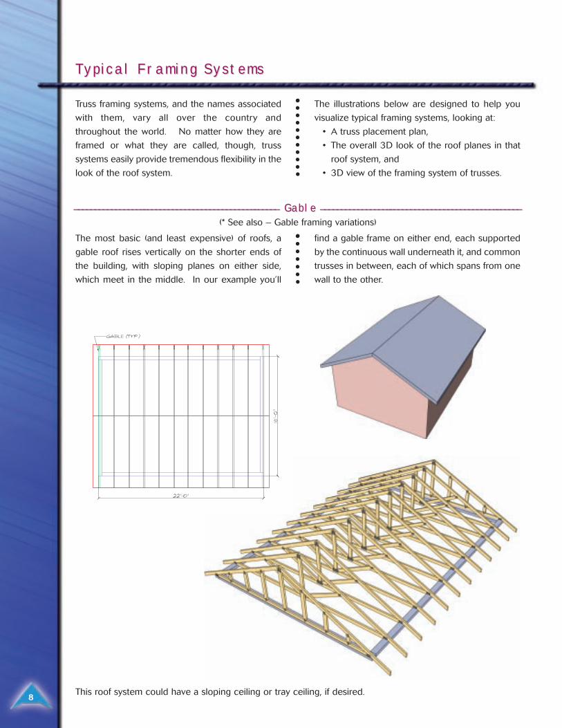
Truss framing systems, and the names associated
with them, vary all over the country and
throughout the world. No matter how they are
framed or what they are called, though, truss
systems easily provide tremendous flexibility in the
look of the roof system.
The illustrations below are designed to help you
visualize typical framing systems, looking at:
• A truss placement plan,
• The overall 3D look of the roof planes in that
roof system, and
• 3D view of the framing system of trusses.
TTypical Framing Systemsypical Framing Systems
8
The most basic (and least expensive) of roofs, a
gable roof rises vertically on the shorter ends of
the building, with sloping planes on either side,
which meet in the middle. In our example you’ll
find a gable frame on either end, each supported
by the continuous wall underneath it, and common
trusses in between, each of which spans from one
wall to the other.
______________________________________________________________________________________________ ______ Gable Gable ____________________________________________________________________________________________ ______
(* See also – Gable framing variations)
This roof system could have a sloping ceiling or tray ceiling, if desired.
9
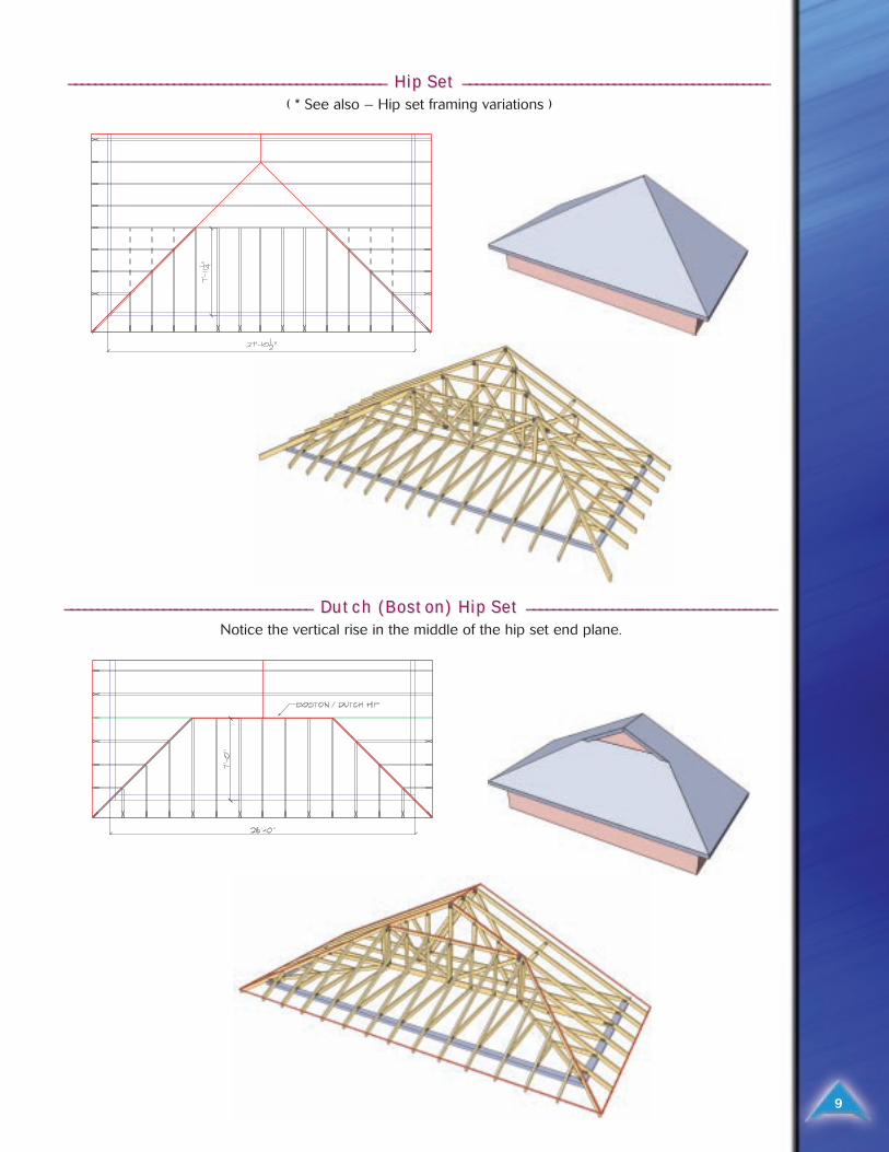
_____________________________________________________________________________________________ _____ Hip Set Hip Set ________________________________________________________________________________________ ______
( * See also – Hip set framing variations )
_______________________________________________________ _____________________ Dutch (Boston) Hip Set Dutch (Boston) Hip Set _________________________________________________________________________ _____
Notice the vertical rise in the middle of the hip set end plane.
10
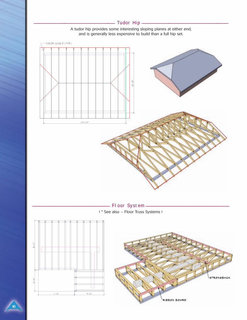
______________________________________________________________________________________ ____ TTudor Hip udor Hip __________________________________________________________________________________________ ______
A tudor hip provides some interesting sloping planes at either end, and is generally less expensive to build than a full hip set.
__________________________________________________________________________________ ____ Floor System Floor System _____________________________________________________________ _______________________________
( * See also – Floor Truss Systems )
Gable Framing VGable Framing Variationsariations
11
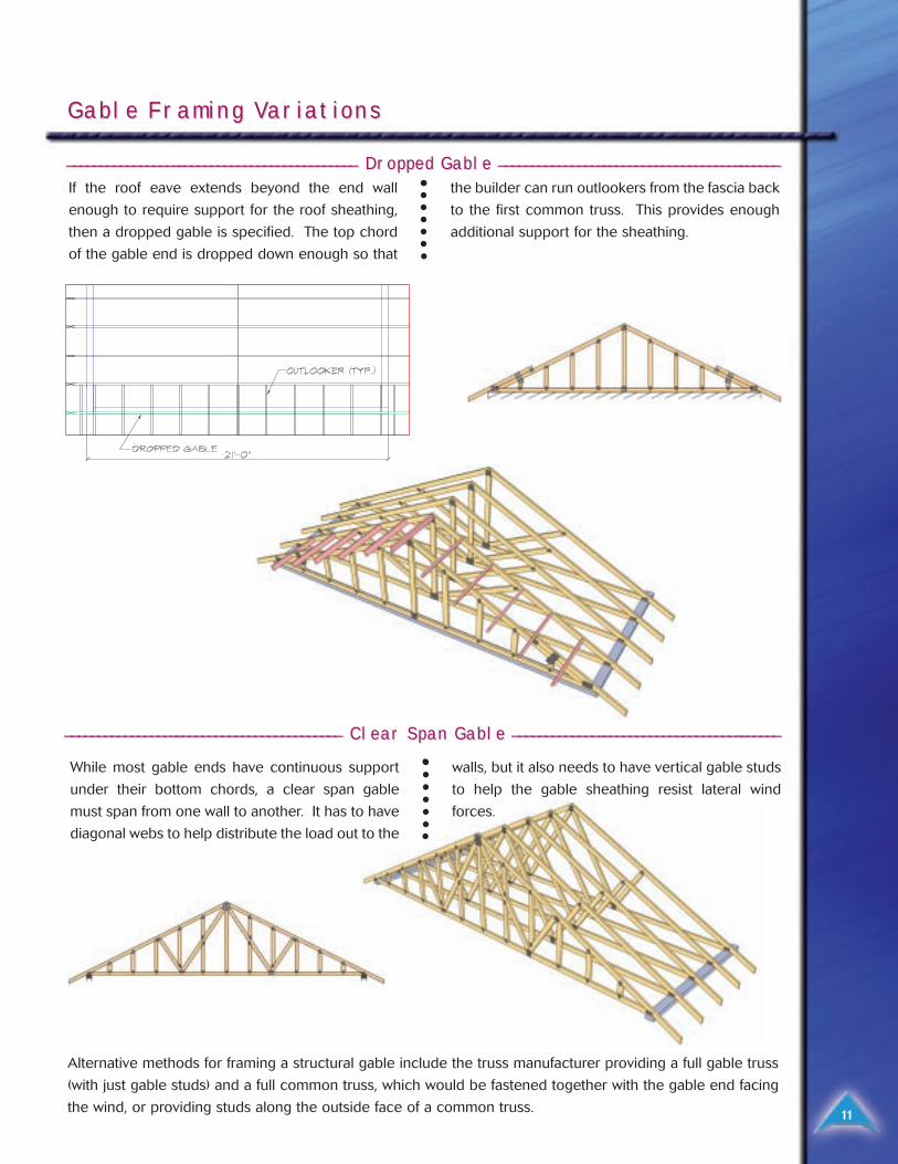
If the roof eave extends beyond the end wall
enough to require support for the roof sheathing,
then a dropped gable is specified. The top chord
of the gable end is dropped down enough so that
the builder can run outlookers from the fascia back
to the first common truss. This provides enough
additional support for the sheathing.
_____________________________________________________________ ___________________________ DrDropped Gable opped Gable ________________________________________________________________________________ ______
___________________________________________________________ _________________________ Clear Span Gable Clear Span Gable ____________________________________________________________________________ ______
While most gable ends have continuous support
under their bottom chords, a clear span gable
must span from one wall to another. It has to have
diagonal webs to help distribute the load out to the
walls, but it also needs to have vertical gable studs
to help the gable sheathing resist lateral wind
forces.
Alternative methods for framing a structural gable include the truss manufacturer providing a full gable truss
(with just gable studs) and a full common truss, which would be fastened together with the gable end facing
the wind, or providing studs along the outside face of a common truss.
12
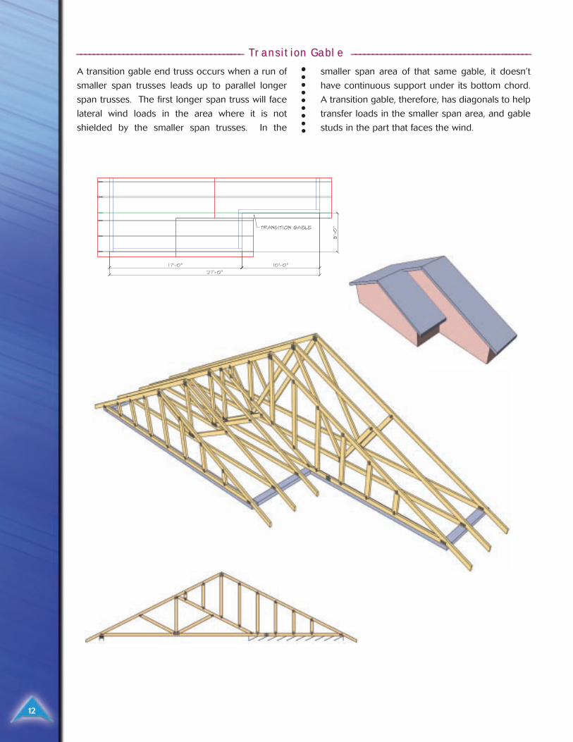
_____________________________________________________________________________ ___ TTransition Gable ransition Gable ________________________________________________________________________________ ______
A transition gable end truss occurs when a run of
smaller span trusses leads up to parallel longer
span trusses. The first longer span truss will face
lateral wind loads in the area where it is not
shielded by the smaller span trusses. In the
smaller span area of that same gable, it doesn’t
have continuous support under its bottom chord.
A transition gable, therefore, has diagonals to help
transfer loads in the smaller span area, and gable
studs in the part that faces the wind.
Under the planes of a hip set roof, there are many
different methods used to frame the trusses.
Preferences for any given system hinges upon
builder preferences, manufacturing efficiencies,
cost, and ceiling requirements. Some of the most
common hip systems are outlined below.
Hip Set Framing VHip Set Framing Variationsariations
13
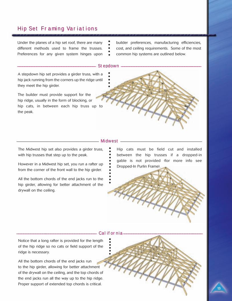
_______________________________________________________________ _____________________________ Stepdown Stepdown ________________________________________________________________________________________ ______
_________________________________________________________________ _______________________________ Midwest Midwest __________________________________________________________________________________________ ______
Notice that a long rafter is provided for the length
of the hip ridge so no cats or field support of the
ridge is necessary.
All the bottom chords of the end jacks run
to the hip girder, allowing for better attachment
of the drywall on the ceiling, and the top chords of
the end jacks run all the way up to the hip ridge.
Proper support of extended top chords is critical.
________________________________________________________________ ______________________________ CaliforCaliforniania________________________________________________________________________________________ ______
A stepdown hip set provides a girder truss, with a
hip jack running from the corners up the ridge until
they meet the hip girder.
The builder must provide support for the
hip ridge, usually in the form of blocking, or
hip cats, in between each hip truss up to
the peak.
The Midwest hip set also provides a girder truss,
with hip trusses that step up to the peak.
However in a Midwest hip set, you run a rafter up
from the corner of the front wall to the hip girder.
All the bottom chords of the end jacks run to the
hip girder, allowing for better attachment of the
drywall on the ceiling.
Hip cats must be field cut and installed
between the hip trusses if a dropped-in
gable is not provided (for more info see
Dropped-In Purlin Frame).
14
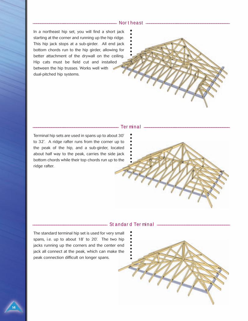
_______________________________________________________________ _____________________________ NorNortheast theast ____________________________________________________________________________________________
In a northeast hip set, you will find a short jack
starting at the corner and running up the hip ridge.
This hip jack stops at a sub-girder. All end jack
bottom chords run to the hip girder, allowing for
better attachment of the drywall on the ceiling.
Hip cats must be field cut and installed
between the hip trusses. Works well with
dual-pitched hip systems.
________________________________________________________________ ______________________________ TTererminal minal ______________________________________________________________________________________________
Terminal hip sets are used in spans up to about 30'
to 32'. A ridge rafter runs from the corner up to
the peak of the hip, and a sub-girder, located
about half way to the peak, carries the side jack
bottom chords while their top chords run up to the
ridge rafter.
__________________________________________________________ ________________________ StandarStandard Td Tererminal minal ________________________________________________________________________________
The standard terminal hip set is used for very small
spans, i.e. up to about 18’ to 20’. The two hip
jacks running up the corners and the center end
jack all connect at the peak, which can make the
peak connection difficult on longer spans.
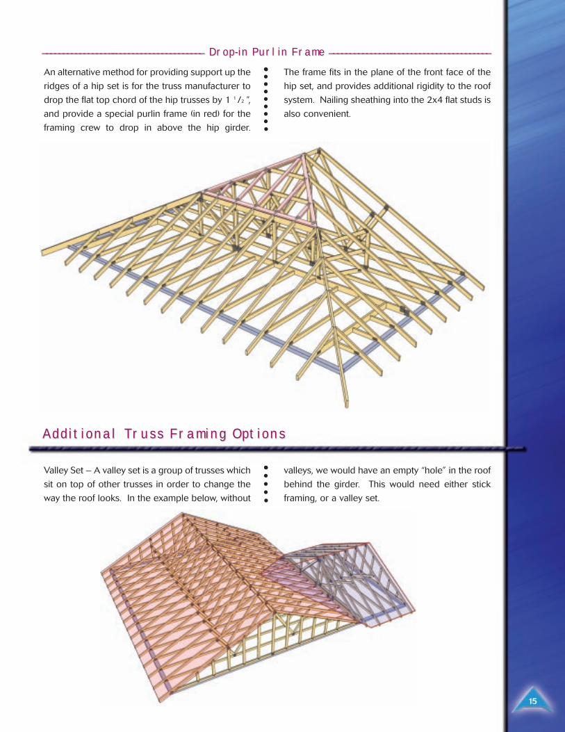
________________________________________________________ ______________________ DrDrop-in Purlin Frame op-in Purlin Frame ______________________________________________________________________________
An alternative method for providing support up the
ridges of a hip set is for the truss manufacturer to
drop the flat top chord of the hip trusses by 1 1 /2 ”,
and provide a special purlin frame (in red) for the
framing crew to drop in above the hip girder.
The frame fits in the plane of the front face of the
hip set, and provides additional rigidity to the roof
system. Nailing sheathing into the 2x4 flat studs is
also convenient.
Additional TAdditional Trruss Framing Optionsuss Framing Options
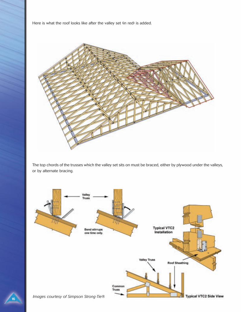
Valley Set – A valley set is a group of trusses which
sit on top of other trusses in order to change the
way the roof looks. In the example below, without
valleys, we would have an empty “hole” in the roof
behind the girder. This would need either stick
framing, or a valley set.
15
16
Here is what the roof looks like after the valley set (in red) is added.
The top chords of the trusses which the valley set sits on must be braced, either by plywood under the valleys,
or by alternate bracing.
Images courtesy of Simpson Strong-Tie®
17
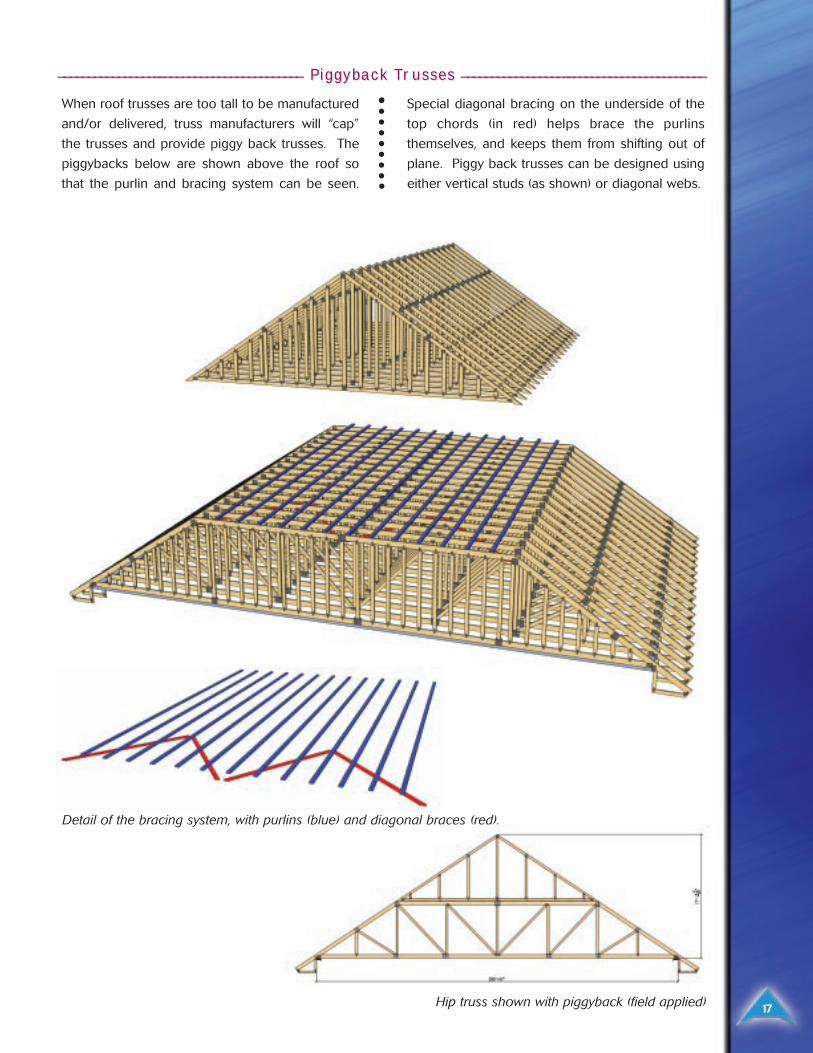
__________________________________________________________ ________________________ Piggyback TPiggyback Trrusses usses __________________________________________________________________________________
When roof trusses are too tall to be manufactured
and/or delivered, truss manufacturers will “cap”
the trusses and provide piggy back trusses. The
piggybacks below are shown above the roof so
that the purlin and bracing system can be seen.
Special diagonal bracing on the underside of the
top chords (in red) helps brace the purlins
themselves, and keeps them from shifting out of
plane. Piggy back trusses can be designed using
either vertical studs (as shown) or diagonal webs.
Detail of the bracing system, with purlins (blue) and diagonal braces (red).
Hip truss shown with piggyback (field applied)
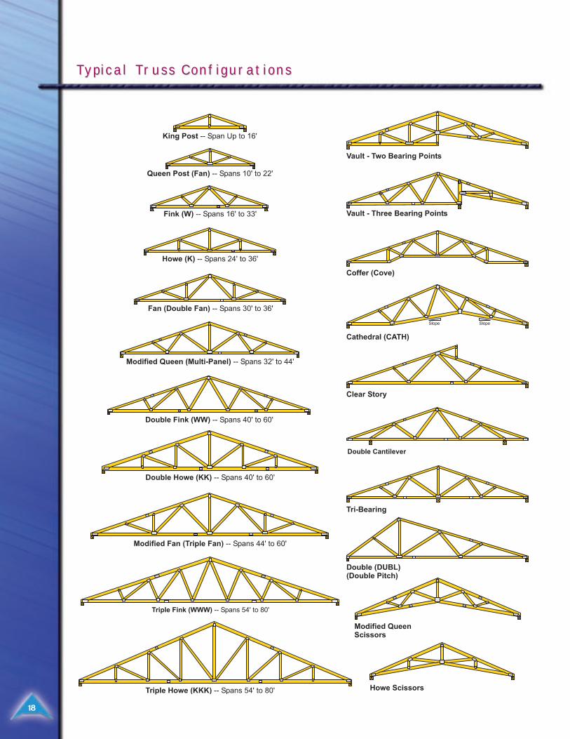
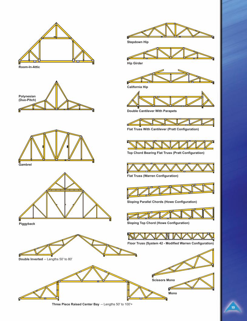
TTypical Typical Trruss Configurationsuss Configurations
18
19
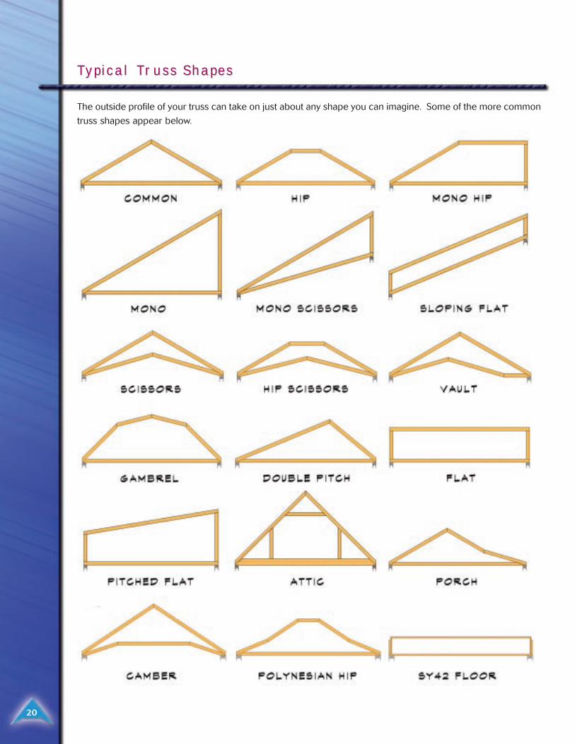
TTypical Typical Trruss Shapesuss Shapes
20
The outside profile of your truss can take on just about any shape you can imagine. Some of the more common
truss shapes appear below.
TTypical Bearing / Heel Conditionsypical Bearing / Heel Conditions
21
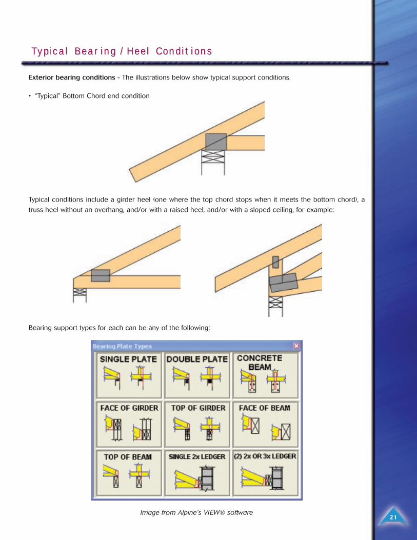
Exterior bearing conditions - The illustrations below show typical support conditions.
• “Typical” Bottom Chord end condition
Typical conditions include a girder heel (one where the top chord stops when it meets the bottom chord), a
truss heel without an overhang, and/or with a raised heel, and/or with a sloped ceiling, for example:
Bearing support types for each can be any of the following:
Image from Alpine’s VIEW® software
22
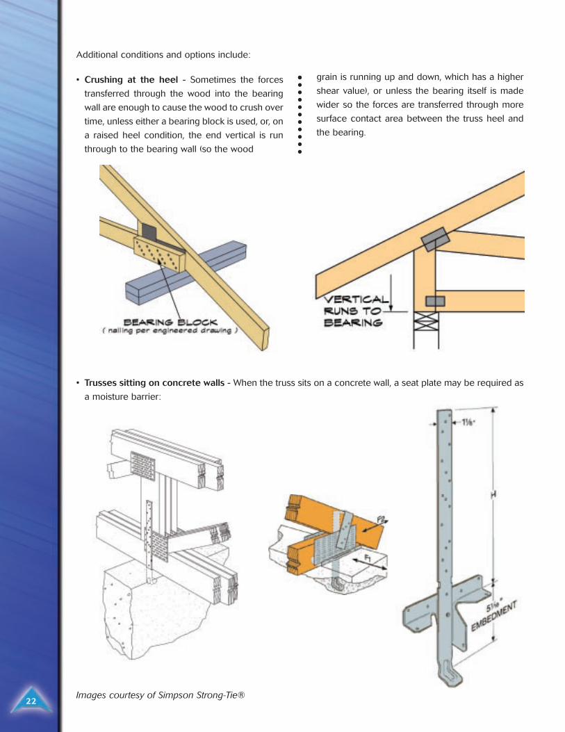
Additional conditions and options include:
• Crushing at the heel - Sometimes the forces
transferred through the wood into the bearing
wall are enough to cause the wood to crush over
time, unless either a bearing block is used, or, on
a raised heel condition, the end vertical is run
through to the bearing wall (so the wood
grain is running up and down, which has a higher
shear value), or unless the bearing itself is made
wider so the forces are transferred through more
surface contact area between the truss heel and
the bearing.
• Trusses sitting on concrete walls - When the truss sits on a concrete wall, a seat plate may be required as
a moisture barrier:
Images courtesy of Simpson Strong-Tie®
23
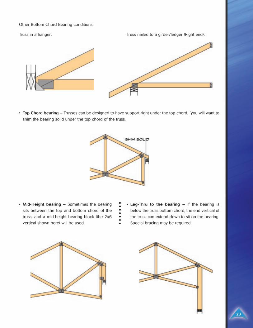
Other Bottom Chord Bearing conditions:
Truss in a hanger: Truss nailed to a girder/ledger (Right end):
• Mid-Height bearing – Sometimes the bearing
sits between the top and bottom chord of the
truss, and a mid-height bearing block (the 2x6
vertical shown here) will be used.
• Leg-Thru to the bearing – If the bearing is
below the truss bottom chord, the end vertical of
the truss can extend down to sit on the bearing.
Special bracing may be required.
• Top Chord bearing – Trusses can be designed to have support right under the top chord. You will want to
shim the bearing solid under the top chord of the truss.
24
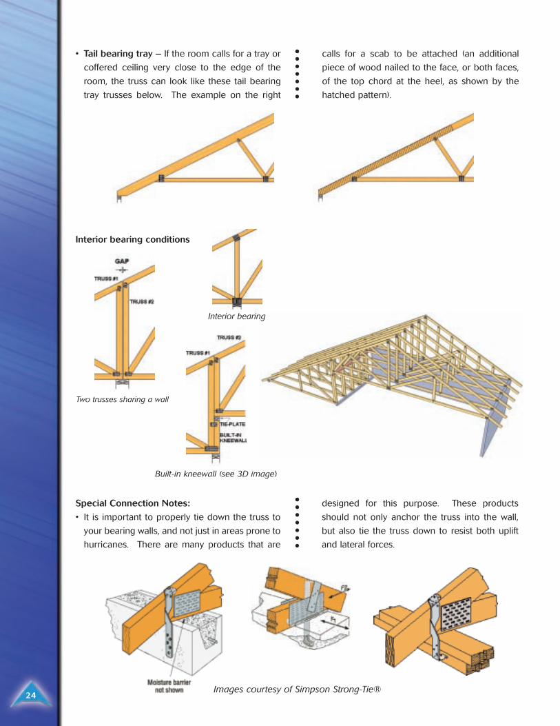
• Tail bearing tray – If the room calls for a tray or
coffered ceiling very close to the edge of the
room, the truss can look like these tail bearing
tray trusses below. The example on the right
calls for a scab to be attached (an additional
piece of wood nailed to the face, or both faces,
of the top chord at the heel, as shown by the
hatched pattern).
Images courtesy of Simpson Strong-Tie®
Special Connection Notes:
• It is important to properly tie down the truss to
your bearing walls, and not just in areas prone to
hurricanes. There are many products that are
designed for this purpose. These products
should not only anchor the truss into the wall,
but also tie the truss down to resist both uplift
and lateral forces.
Interior bearing conditions
Two trusses sharing a wall
Interior bearing
Built-in kneewall (see 3D image}
25
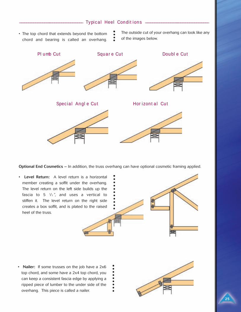
• The top chord that extends beyond the bottom
chord and bearing is called an overhang.
The outside cut of your overhang can look like any
of the images below.
________________________________________________________________________ TTypical Heel Conditions ypical Heel Conditions ________________________________________________________________________
• Level Return: A level return is a horizontal
member creating a soffit under the overhang.
The level return on the left side builds up the
fascia to 5 1/2 ”, and uses a vertical to
stiffen it. The level return on the right side
creates a box soffit, and is plated to the raised
heel of the truss.
Optional End Cosmetics – In addition, the truss overhang can have optional cosmetic framing applied.
• Nailer: If some trusses on the job have a 2x6
top chord, and some have a 2x4 top chord, you
can keep a consistent fascia edge by applying a
ripped piece of lumber to the under side of the
overhang. This piece is called a nailer.
Plumb CutPlumb Cut SquarSquare Cute Cut
Special Angle CutSpecial Angle Cut Horizontal CutHorizontal Cut
Double CutDouble Cut
26
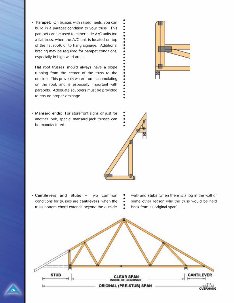
• Parapet: On trusses with raised heels, you can
build in a parapet condition to your truss. This
parapet can be used to either hide A/C units (on
a flat truss, when the A/C unit is located on top
of the flat roof), or to hang signage. Additional
bracing may be required for parapet conditions,
especially in high wind areas.
Flat roof trusses should always have a slope
running from the center of the truss to the
outside. This prevents water from accumulating
on the roof, and is especially important with
parapets. Adequate scuppers must be provided
to ensure proper drainage.
• Cantilevers and Stubs – Two common
conditions for trusses are cantilevers (when the
truss bottom chord extends beyond the outside
wall) and stubs (when there is a jog in the wall or
some other reason why the truss would be held
back from its original span).
• Mansard ends: For storefront signs or just for
another look, special mansard jack trusses can
be manufactured.
_____________________________________________________________ ___________________________ WWeb Bracing eb Bracing ________________________________________________________________________________________
Bracing ExamplesBracing Examples
27
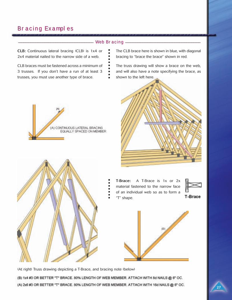
CLB: Continuous lateral bracing (CLB) is 1x4 or
2x4 material nailed to the narrow side of a web.
CLB braces must be fastened across a minimum of
3 trusses. If you don’t have a run of at least 3
trusses, you must use another type of brace.
The CLB brace here is shown in blue, with diagonal
bracing to “brace the brace” shown in red.
The truss drawing will show a brace on the web,
and will also have a note specifying the brace, as
shown to the left here.
T-Brace: A T-Brace is 1x or 2x
material fastened to the narrow face
of an individual web so as to form a
“T” shape.
(At right) Truss drawing depicting a T-Brace, and bracing note (below)
28
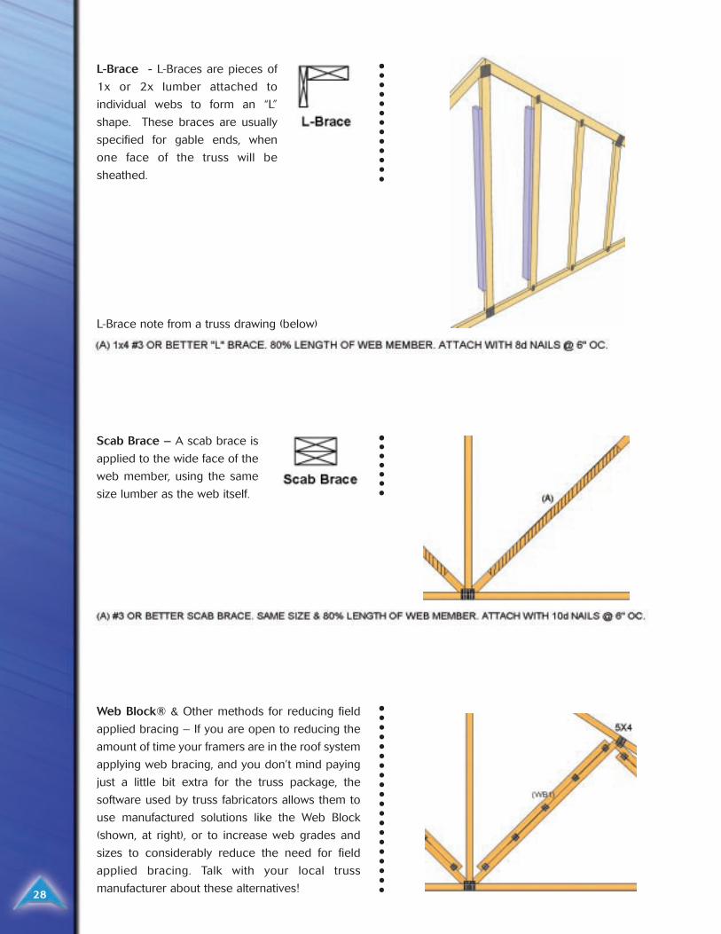
L-Brace - L-Braces are pieces of
1x or 2x lumber attached to
individual webs to form an “L”
shape. These braces are usually
specified for gable ends, when
one face of the truss will be
sheathed.
Scab Brace – A scab brace is
applied to the wide face of the
web member, using the same
size lumber as the web itself.
Web Block® & Other methods for reducing field
applied bracing – If you are open to reducing the
amount of time your framers are in the roof system
applying web bracing, and you don’t mind paying
just a little bit extra for the truss package, the
software used by truss fabricators allows them to
use manufactured solutions like the Web Block
(shown, at right), or to increase web grades and
sizes to considerably reduce the need for field
applied bracing. Talk with your local truss
manufacturer about these alternatives!
L-Brace note from a truss drawing (below)
ErErection of Tection of Trrussesusses
29
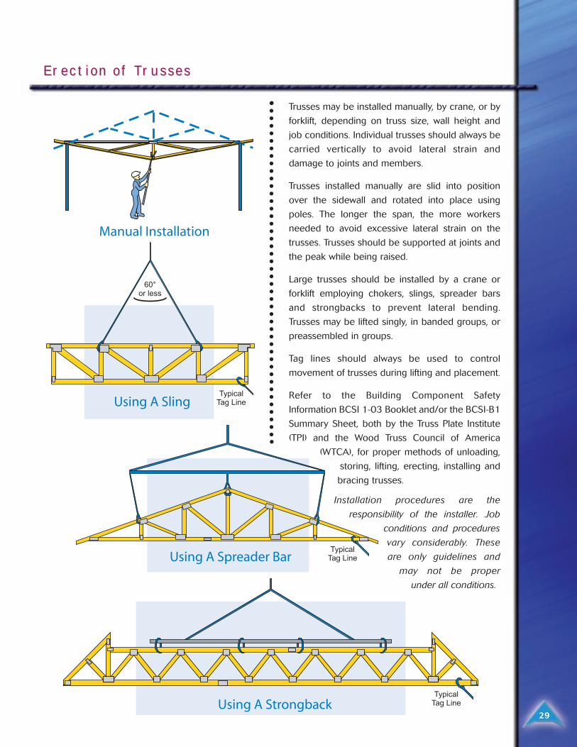
Trusses may be installed manually, by crane, or by
forklift, depending on truss size, wall height and
job conditions. Individual trusses should always be
carried vertically to avoid lateral strain and
damage to joints and members.
Trusses installed manually are slid into position
over the sidewall and rotated into place using
poles. The longer the span, the more workers
needed to avoid excessive lateral strain on the
trusses. Trusses should be supported at joints and
the peak while being raised.
Large trusses should be installed by a crane or
forklift employing chokers, slings, spreader bars
and strongbacks to prevent lateral bending.
Trusses may be lifted singly, in banded groups, or
preassembled in groups.
Tag lines should always be used to control
movement of trusses during lifting and placement.
Refer to the Building Component Safety
Information BCSI 1-03 Booklet and/or the BCSI-B1
Summary Sheet, both by the Truss Plate Institute
(TPI) and the Wood Truss Council of America
(WTCA), for proper methods of unloading,
storing, lifting, erecting, installing and
bracing trusses.
Installation procedures are the
responsibility of the installer. Job
conditions and procedures
vary considerably. These
are only guidelines and
may not be proper
under all conditions.
TTemporaremporary Bracing y Bracing
30
All trusses must be securely braced, both during
erection and after permanent installation.
Individual trusses are designed only as structural
components. Responsibility for proper bracing
always lies with the building designer and
contractor for they are familiar with local and job-
site conditions and overall building design. All
trusses should be installed straight, plumb and
aligned at the specified spacing. Trusses should
also be inspected for structural damage.
There are two types of bracing. Temporary bracing
is used during erection to hold the trusses until
permanent bracing, sheathing and ceilings are in
place. Permanent bracing makes the truss
component an integral part of the roof and
building structure. Temporary and permanent
bracing includes diagonal bracing, cross bracing
and lateral bracing.
Permanent lateral bracing, as may be required by
truss design to reduce the buckling length of
individual truss members, is part of the truss
design and is the only bracing specified on the
design drawing. This bracing must be sufficiently
anchored or restrained by diagonal bracing to
prevent its movement. Most truss designs assume
continuous top and bottom chord lateral support
from sheathing and ceilings. Extra lateral and
diagonal bracing is required if this is not the case.
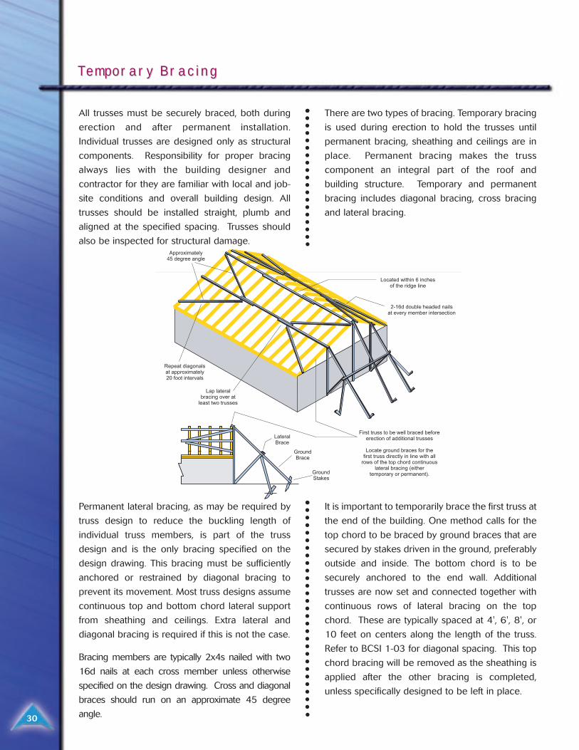
Bracing members are typically 2x4s nailed with two
16d nails at each cross member unless otherwise
specified on the design drawing. Cross and diagonal
braces should run on an approximate 45 degree
angle.
It is important to temporarily brace the first truss at
the end of the building. One method calls for the
top chord to be braced by ground braces that are
secured by stakes driven in the ground, preferably
outside and inside. The bottom chord is to be
securely anchored to the end wall. Additional
trusses are now set and connected together with
continuous rows of lateral bracing on the top
chord. These are typically spaced at 4', 6', 8', or
10 feet on centers along the length of the truss.
Refer to BCSI 1-03 for diagonal spacing. This top
chord bracing will be removed as the sheathing is
applied after the other bracing is completed,
unless specifically designed to be left in place.
31
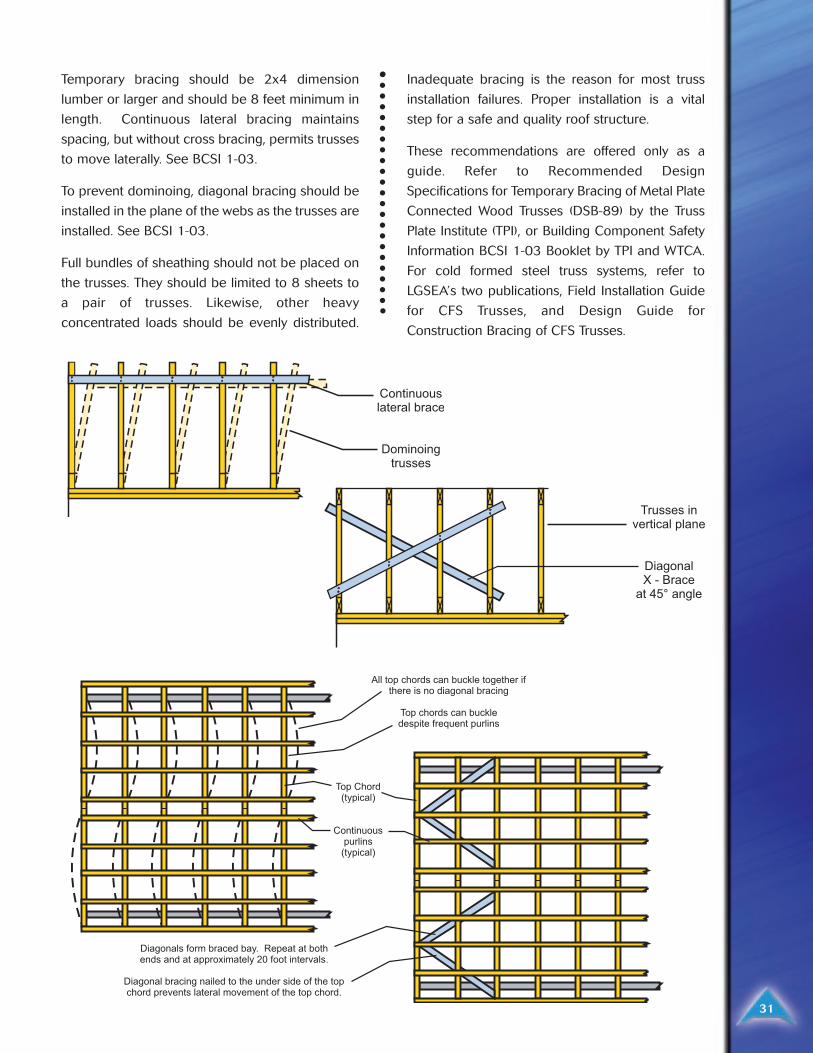
Temporary bracing should be 2x4 dimension
lumber or larger and should be 8 feet minimum in
length. Continuous lateral bracing maintains
spacing, but without cross bracing, permits trusses
to move laterally. See BCSI 1-03.
To prevent dominoing, diagonal bracing should be
installed in the plane of the webs as the trusses are
installed. See BCSI 1-03.
Full bundles of sheathing should not be placed on
the trusses. They should be limited to 8 sheets to
a pair of trusses. Likewise, other heavy
concentrated loads should be evenly distributed.
Inadequate bracing is the reason for most truss
installation failures. Proper installation is a vital
step for a safe and quality roof structure.
These recommendations are offered only as a
guide. Refer to Recommended Design
Specifications for Temporary Bracing of Metal Plate
Connected Wood Trusses (DSB-89) by the Truss
Plate Institute (TPI), or Building Component Safety
Information BCSI 1-03 Booklet by TPI and WTCA.
For cold formed steel truss systems, refer to
LGSEA’s two publications, Field Installation Guide
for CFS Trusses, and Design Guide for
Construction Bracing of CFS Trusses.
Bracing is extremely IMPORTANT!! Every roof
system needs adequate bracing. The purpose of
most bracing is to ensure that the trusses and truss
members remain straight and do not bow out of
their plane. Inadequate, improper or incorrectly
installed bracing can lead to collapses, failures and
serious accidents. An engineered bracing system
will avoid these pitfalls and ensure the structural
integrity of the truss system.
Trusses need to be braced during installation,
which is called Temporary Bracing, and they need
Permanent Bracing which will remain installed for
the life of the roof system.
Temporary Bracing Guidelines: For metal plate
connected wood truss systems, refer to BCSI 1-03
for proper installation bracing guidelines. For cold
formed steel truss systems, refer to LGSEA’s two
publications, Field Installation Guide for CFS
Trusses, and Design Guide for Construction
Bracing of CFS Trusses.
CHECKLIST FOR TRUSS BRACINGCHECKLIST FOR TRUSS BRACING
32
_____________________________________________ ___________ PerPermanent Bracing System Checklistmanent Bracing System Checklist ________________________________________________________
1. Top Chord Planes� Do top chord planes have structural sheathing (plywood, OSB, metal deck)?
� If not, do you have a purlin system, with both purlins (perpendicular to the trusses) and diagonal bracing?Purlin systems can be used for standing seam roofs, or with structural sheathing applied on top of thepurlins. Either way, a diagonal brace system must be engineered. Refer to sealed engineered trussdesigns for specified purlin spacing.
2. Web Bracing – be sure to reference sealed engineered truss designs for proper web bracing callouts.� CLB Bracing crosses a minimum of 3 trusses, including diagonal bracing to “brace the bracing”?
� Properly installed T-Braces, L-Braces (especially on gable ends), Scab Braces, and other web bracingsystems such as the Web Block?
3. Bottom Chord Planes� Do bottom chord planes have structural sheathing directly attached? In many cases drywall is
considered by the building designer to be lateral bracing, but in some cases it is not.
� If not, then you will need a purlin system, which can be attached to the top of your bottom chords, andthose purlins will need diagonal braces.
� If you have any suspended ceilings, do you have a purlin system (including diagonal bracing) on the topor bottom of those bottom chords?
4. Additional Bracing Concerns� Piggyback Systems – If you have piggyback systems, do you have a purlin system installed to support
the bottom chord of the piggyback, as well as purlins and diagonal braces to ensure that the flat topchords of the hip trusses stay in plane?
� Valley Sets – Under the valley trusses, do you have structural sheathing, or other engineered bracingsystem for the top chords of the trusses underneath? Are the valley bottom chords adequately fasteneddown?
� High Heel Heights at a Wall – for trusses with heel heights greater than a nominal 2x6, is special heelblocking required and installed?
� Blocking For the Ridge in Hip Systems – Have you added blocks on the ridge between each hip truss(where a rafter or extended hip jack top chord doesn’t extend to the peak of the hip system) to supportthe decking?
Floor Systems Floor Systems
33
Another popular application for truss systems is in
floor systems. Floor systems can be trussed,
conventionally framed, or built with engineered
wood products such as I-Joists. Both trusses and
engineered wood products are engineered, and
have wider nailing surfaces for the floor decking.
Trusses are built with open chases for ductwork
and have natural open spaces for plumbing and
electrical wiring. Some engineered wood
products have specified or marked notches that
can be removed to allow for the same.
Floor truss systems are sometimes called System
42’s, because to build them manufacturers turn
the 2x4’s on their side. This allows for shallow
depths as well as a 3 1/2” nailing surface. Some
floors are built from 3x2’s, others from 2x4’s.
Floor trusses can be manufactured with many
different possible end conditions to accommodate
different installation needs; around raised walls,
pocketed beams, headers around stairways, etc.
In addition, some manufacturers are taking
advantage of adding an I-Joist to the end of a truss
to make it a trim-able end. Then the truss can be
manufactured just a bit long, and easily trimmed
back as needed in the field. Two of the most
common web patterns for floor trusses appear
below:
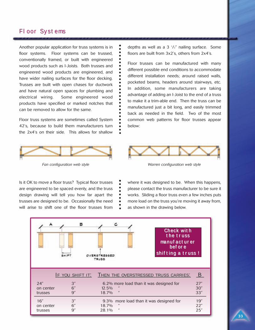
Is it OK to move a floor truss? Typical floor trusses
are engineered to be spaced evenly, and the truss
design drawing will tell you how far apart the
trusses are designed to be. Occasionally the need
will arise to shift one of the floor trusses from
where it was designed to be. When this happens,
please contact the truss manufacturer to be sure it
works. Sliding a floor truss even a few inches puts
more load on the truss you’re moving it away from,
as shown in the drawing below.
Fan configuration web style Warren configuration web style
IIFF YOUYOU SHIFTSHIFT ITIT:: TTHENHEN THETHE OVERSTRESSEDOVERSTRESSED TRUSSTRUSS CARRIESCARRIES:: B B
24” 3” 6.2% more load than it was designed for 27”on center 6” 12.5% “ 30”trusses 9” 18.7% “ 33”
16” 3” 9.3% more load than it was designed for 19”on center 6” 18.7% “ 22”trusses 9” 28.1% “ 25”
Check with Check with the trthe truss uss
manufacturmanufacturererbeforbefore e
shifting a trshifting a truss ! uss !
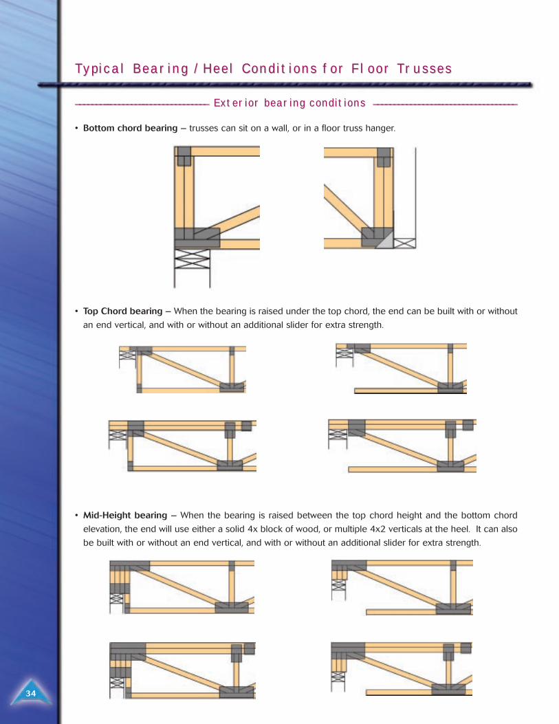
__________________________________________________ ________________ Exterior bearing conditions Exterior bearing conditions ______________________________________________________________________
• Bottom chord bearing – trusses can sit on a wall, or in a floor truss hanger.
• Top Chord bearing – When the bearing is raised under the top chord, the end can be built with or without
an end vertical, and with or without an additional slider for extra strength.
• Mid-Height bearing – When the bearing is raised between the top chord height and the bottom chord
elevation, the end will use either a solid 4x block of wood, or multiple 4x2 verticals at the heel. It can also
be built with or without an end vertical, and with or without an additional slider for extra strength.
TTypical Bearing / Heel Conditions for Floor Typical Bearing / Heel Conditions for Floor Trrussesusses
34

35
__________________________________________________ ________________ Interior bearing conditions Interior bearing conditions ______________________________________________________________________
• This truss is supported by an interior load bearing wall.
• Cut chord condition – Over an interior load
bearing wall, a truss can also be built with a cut
chord condition. This truss is designed to be cut
into two separate trusses in the field.
• Beam Pocket – This truss has a “pocket” built into it so the support can be recessed up into the truss.
• Threaded Beam – This truss has an opening
designed to bear on a beam, which will be
designed and then threaded into the truss to help
support it.
36
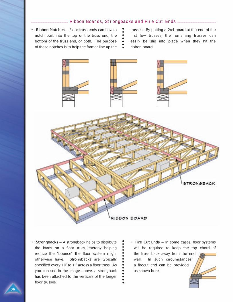
_____________________ _____________________ Ribbon BoarRibbon Boards, Strds, Strongbacks and Firongbacks and Fire Cut Ends e Cut Ends ______________________ ______________________
• Ribbon Notches – Floor truss ends can have a
notch built into the top of the truss end, the
bottom of the truss end, or both. The purpose
of these notches is to help the framer line up the
trusses. By putting a 2x4 board at the end of the
first few trusses, the remaining trusses can
easily be slid into place when they hit the
ribbon board.
• Strongbacks – A strongback helps to distribute
the loads on a floor truss, thereby helping
reduce the “bounce” the floor system might
otherwise have. Strongbacks are typically
specified every 10’ to 11’ across a floor truss. As
you can see in the image above, a strongback
has been attached to the verticals of the longer
floor trusses.
• Fire Cut Ends – In some cases, floor systems
will be required to keep the top chord of
the truss back away from the end
wall. In such circumstances,
a firecut end can be provided,
as shown here.

While there are many steel truss solutions in the
marketplace, Alpine’s TrusSteel products are the
best, providing:
• Lightweight trusses: One worker alone can
typically lift a 35’ truss by himself. TrusSteel
trusses are easy to deliver, handle, and install.
• Meets fire code non-combustible materials
requirements.
• Immune to insect damage, material deterioration
and shrinkage, as well as from dry-wall nail pops.
• It’s an engineered product, so you can build with
confidence!
• The material is stiff, so installing drywall or other
ceiling materials is easier.
Steel TSteel Trrussesusses
37
Ask Charlie VAsk Charlie V..
38
Strength-wise, what is the difference between
conventional framing and trusses? Isn’t
conventional framing as strong?
CV: It should be, but, how do you know? Trusses
are designed with 2 to 3 times the design
load. They are calculated and tested to
perform at that level. The conventional
framing depends on how good the
carpenter in charge of the framing
is. The only thing he knows about loading
is what's been done in the past from a
skilled carpenter. Most don't have formal
training today.
Why use trusses?
CV: Trusses offer virtually unlimited architectural
versatility - complete flexibility of interior
partitioning and room arrangement -
uniformity and accuracy from one truss to
the next - faster and easier erection time -
lightweight (generally 20 to 40 percent less
than most other structural systems) - open
web design - durable. They have a proven
performance record - inspectable and "total
in-place cost" savings.
Esthetically, I can take one basic floor plan
and leave it exactly the same. Yet, from the
outside, I can make it look like four different
floor plans, just by changing the trusses. The only
cost difference is the trusses, not the floor plan. I
am only showing you four; but, with imagination, I
can do a few more elevations.
If I have the resources, I can virtually work all
winter on homes by building the outside shell of
the house in fair weather, and work on the inside
during inclement weather and get a good day's
work done. If I was conventionally framing, my
days would be more subject to the elements.
Most people with construction loans don't get to
their first draw until the roof is dried in. Trusses will
get you there weeks ahead of conventional
framing.
With trusses, if the square foot of the floor plan is
the same, no matter what I do to the floor plan, my
cost difference would be the cost of adding or
deleting a wall. Since trusses can span longer
distances than conventional framing, I don’t often
rely on interior load bearing walls, so you can
make changes to the interior without major
problems. Plus, I can create heavy storage areas
above the ceiling if needed, without changing the
floor plan.
Is it OK to cut a truss in the field?
CV: Structural members of a truss should never
be field cut without proper field repair
For nearly 46 years, Charlie Vaccaro
has worked in virtually every phase
of the truss industry. Originally an
aeronautical engineer, he has
designed truss connector plates
and trusses, started truss plants,
and as been an Alpine production
consultant since 1970. Today, he
serves as a speaker, author and
National Sales and Plant Consultant
for Alpine Engineered Products, Inc.
39
engineering from the truss manufacturer.
Non-structural members, such as overhangs
or filler bottom chords may be cut as long as
they do not interfere with the structural
integrity of the truss.
What is temporary bracing?
CV: Temporary bracing is described as bracing
in WTCA and TPI's BCSI 1-03 as bracing
which is installed to hold the trusses true to
line, dimensions, and plumb. In addition,
temporary bracing holds the trusses in a
stable condition until permanent truss
bracing and other permanent components
such as roof or floor sheathing, joists, or
purlins which contribute to the overall
rigidity of the roof or floor are in place.
What is permanent bracing?
CV: Permanent bracing is bracing that will be
installed in the roof system as a permanent
part of the roof system. The most common
is continuous lateral bracing which is a
member placed and connected at right
angles to a chord or web to prevent buckling
under loads less than design loads. Other
examples are T-braces, L-braces, etc.
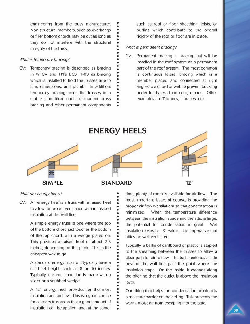
What are energy heels?
CV: An energy heel is a truss with a raised heel
to allow for proper ventilation with increased
insulation at the wall line.
A simple energy truss is one where the top
of the bottom chord just touches the bottom
of the top chord, with a wedge plated on.
This provides a raised heel of about 7-8
inches, depending on the pitch. This is the
cheapest way to go.
A standard energy truss will typically have a
set heel height, such as 8 or 10 inches.
Typically, the end condition is made with a
slider or a snubbed wedge.
A 12" energy heel provides for the most
insulation and air flow. This is a good choice
for scissors trusses so that a good amount of
insulation can be applied; and, at the same
time, plenty of room is available for air flow. The
most important issue, of course, is providing the
proper air flow (ventilation) so that condensation is
minimized. When the temperature difference
between the insulation space and the attic is large,
the potential for condensation is great. Wet
insulation loses its "R" value. It is imperative that
attics be well ventilated.
Typically, a baffle of cardboard or plastic is stapled
to the sheathing between the trusses to allow a
clear path for air to flow. The baffle extends a little
beyond the wall line past the point where the
insulation stops. On the inside, it extends along
the pitch so that the outlet is above the insulation
layer.
One thing that helps the condensation problem is
a moisture barrier on the ceiling. This prevents the
warm, moist air from escaping into the attic.
SIMPLE STANDARD 12”
ENERGY HEELS
40
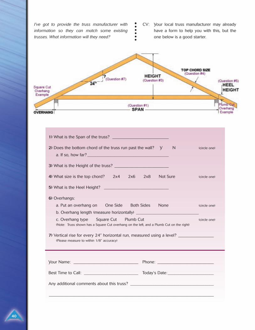
I’ve got to provide the truss manufacturer with
information so they can match some existing
trusses. What information will they need?
CV: Your local truss manufacturer may already
have a form to help you with this, but the
one below is a good starter.
1) What is the Span of the truss? ___________________________
2) Does the bottom chord of the truss run past the wall? Y N (circle one)
a. If so, how far? _______________________________________
3) What is the Height of the truss? __________________________
4) What size is the top chord? 2x4 2x6 2x8 Not Sure (circle one)
5) What is the Heel Height? _______________________________
6) Overhangs:
a. Put an overhang on One Side Both Sides None (circle one)
b. Overhang length (measure horizontally) ______________________________
c. Overhang type Square Cut Plumb Cut (circle one)
(Note: Truss shown has a Square Cut overhang on the left, and a Plumb Cut on the right)
7) Vertical rise for every 24” horizontal run, measured using a level? _________________(Please measure to within 1/8” accuracy)
Your Name: _______________________________ Phone: ___________________________
Best Time to Call: __________________________ Today’s Date:______________________
Any additional comments about this truss? ________________________________________
_______________________________________________________________________________
41
Charlie’s advice on situations to watch out for in
the field:
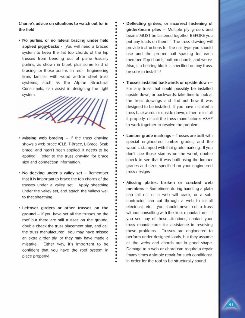
• No purlins, or no lateral bracing under field
applied piggybacks - You will need a braced
system to keep the flat top chords of the hip
trusses from bending out of plane (usually
purlins, as shown in blue), plus some kind of
bracing for those purlins (in red). Engineering
firms familiar with wood and/or steel truss
systems, such as the Alpine Structural
Consultants, can assist in designing the right
system.
• Missing web bracing – If the truss drawing
shows a web brace (CLB, T-Brace, L-Brace, Scab
brace) and hasn’t been applied, it needs to be
applied! Refer to the truss drawing for brace
size and connection information.
• No decking under a valley set – Remember
that it is important to brace the top chords of the
trusses under a valley set. Apply sheathing
under the valley set, and attach the valleys well
to that sheathing.
• Leftover girders or other trusses on the
ground – If you have set all the trusses on the
roof but there are still trusses on the ground,
double check the truss placement plan, and call
the truss manufacturer. You may have missed
an extra girder ply, or they may have made a
mistake. Either way, it’s important to be
confident that you have the roof system in
place properly!
• Deflecting girders, or incorrect fastening of
girder/beam plies – Multiple ply girders and
beams MUST be fastened together BEFORE you
put any loads on them!!! The truss drawing will
provide instructions for the nail type you should
use and the proper nail spacing for each
member (Top chords, bottom chords, and webs).
Also, if a bearing block is specified on any truss,
be sure to install it!
• Trusses installed backwards or upside down –
For any truss that could possibly be installed
upside down, or backwards, take time to look at
the truss drawings and find out how it was
designed to be installed. If you have installed a
truss backwards or upside down, either re-install
it properly, or call the truss manufacturer ASAP
to work together to resolve the problem.
• Lumber grade markings – Trusses are built with
special engineered lumber grades, and the
wood is stamped with that grade marking. If you
don’t see those stamps on the wood, double
check to see that it was built using the lumber
grades and sizes specified on your engineered
truss designs.
• Missing plates, broken or cracked web
members – Sometimes during handling a plate
can fall off, or a web will crack, or a sub-
contractor can cut through a web to install
electrical, etc. You should never cut a truss
without consulting with the truss manufacturer. If
you see any of these situations, contact your
truss manufacturer for assistance in resolving
these problems. Trusses are engineered to
perform under designed loads, but they assume
all the webs and chords are in good shape.
Damage to a web or chord can require a repair
(many times a simple repair for such conditions),
in order for the roof to be structurally sound.
GlossarGlossary of Ty of Terermsms
42
AXIAL FORCE - A push (compression) or pull (tension) force acting along the length of a member [usually
measured in pounds (lbs)].
AXIAL STRESS - The axial force acting along the length of a member, divided by the cross-sectional area of
the member [usually measured in pounds per square inch (psi)].
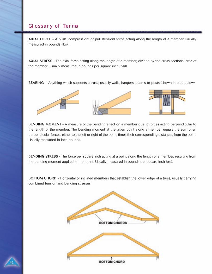
BEARING – Anything which supports a truss; usually walls, hangers, beams or posts (shown in blue below).
BENDING MOMENT - A measure of the bending effect on a member due to forces acting perpendicular to
the length of the member. The bending moment at the given point along a member equals the sum of all
perpendicular forces, either to the left or right of the point, times their corresponding distances from the point.
Usually measured in inch-pounds.
BENDING STRESS - The force per square inch acting at a point along the length of a member, resulting from
the bending moment applied at that point. Usually measured in pounds per square inch (psi).
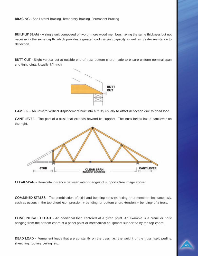
BOTTOM CHORD - Horizontal or inclined members that establish the lower edge of a truss, usually carrying
combined tension and bending stresses.
43
BRACING - See Lateral Bracing, Temporary Bracing, Permanent Bracing
BUILT-UP BEAM - A single unit composed of two or more wood members having the same thickness but not
necessarily the same depth, which provides a greater load carrying capacity as well as greater resistance to
deflection.
BUTT CUT - Slight vertical cut at outside end of truss bottom chord made to ensure uniform nominal span
and tight joints. Usually 1/4-inch.
CAMBER - An upward vertical displacement built into a truss, usually to offset deflection due to dead load.
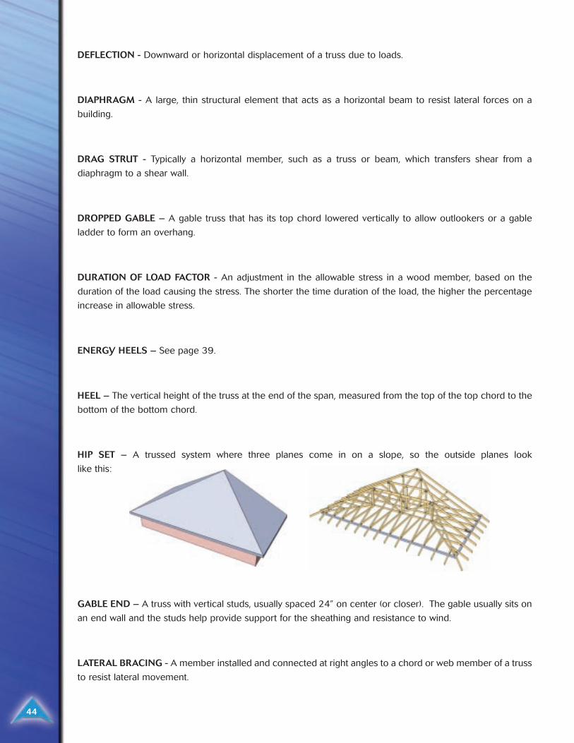
CANTILEVER - The part of a truss that extends beyond its support. The truss below has a cantilever on
the right.
CLEAR SPAN - Horizontal distance between interior edges of supports (see image above).
COMBINED STRESS - The combination of axial and bending stresses acting on a member simultaneously,
such as occurs in the top chord (compression + bending) or bottom chord (tension + bending) of a truss.
CONCENTRATED LOAD - An additional load centered at a given point. An example is a crane or hoist
hanging from the bottom chord at a panel point or mechanical equipment supported by the top chord.
DEAD LOAD - Permanent loads that are constantly on the truss, i.e.: the weight of the truss itself, purlins,
sheathing, roofing, ceiling, etc.
44
DEFLECTION - Downward or horizontal displacement of a truss due to loads.
DIAPHRAGM - A large, thin structural element that acts as a horizontal beam to resist lateral forces on a
building.
DRAG STRUT - Typically a horizontal member, such as a truss or beam, which transfers shear from a
diaphragm to a shear wall.
DROPPED GABLE – A gable truss that has its top chord lowered vertically to allow outlookers or a gable
ladder to form an overhang.
DURATION OF LOAD FACTOR - An adjustment in the allowable stress in a wood member, based on the
duration of the load causing the stress. The shorter the time duration of the load, the higher the percentage
increase in allowable stress.
ENERGY HEELS – See page 39.
HEEL – The vertical height of the truss at the end of the span, measured from the top of the top chord to the
bottom of the bottom chord.
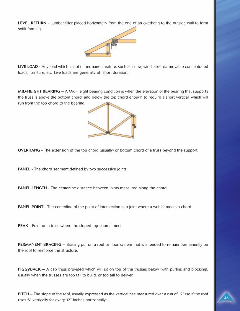
HIP SET – A trussed system where three planes come in on a slope, so the outside planes look
like this:
GABLE END – A truss with vertical studs, usually spaced 24” on center (or closer). The gable usually sits on
an end wall and the studs help provide support for the sheathing and resistance to wind.
LATERAL BRACING - A member installed and connected at right angles to a chord or web member of a truss
to resist lateral movement.
LEVEL RETURN - Lumber filler placed horizontally from the end of an overhang to the outside wall to form
soffit framing.
LIVE LOAD - Any load which is not of permanent nature, such as snow, wind, seismic, movable concentrated
loads, furniture, etc. Live loads are generally of short duration.
MID-HEIGHT BEARING – A Mid-Height bearing condition is when the elevation of the bearing that supports
the truss is above the bottom chord, and below the top chord enough to require a short vertical, which will
run from the top chord to the bearing.
OVERHANG - The extension of the top chord (usually) or bottom chord of a truss beyond the support.
PANEL - The chord segment defined by two successive joints.
PANEL LENGTH - The centerline distance between joints measured along the chord.
PANEL POINT - The centerline of the point of intersection in a joint where a web(s) meets a chord.
PEAK - Point on a truss where the sloped top chords meet.
PERMANENT BRACING – Bracing put on a roof or floor system that is intended to remain permanently on
the roof to reinforce the structure.
PIGGYBACK – A cap truss provided which will sit on top of the trusses below (with purlins and blocking),
usually when the trusses are too tall to build, or too tall to deliver.
PITCH – The slope of the roof, usually expressed as the vertical rise measured over a run of 12” (so if the roof
rises 6” vertically for every 12” inches horizontally). 45
46
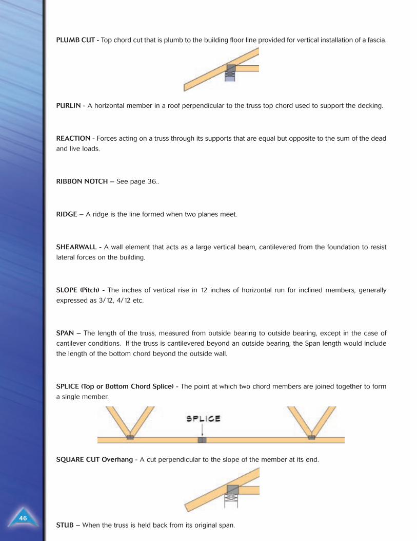
PLUMB CUT - Top chord cut that is plumb to the building floor line provided for vertical installation of a fascia.
PURLIN - A horizontal member in a roof perpendicular to the truss top chord used to support the decking.
REACTION - Forces acting on a truss through its supports that are equal but opposite to the sum of the dead
and live loads.
RIBBON NOTCH – See page 36..
RIDGE – A ridge is the line formed when two planes meet.
SHEARWALL - A wall element that acts as a large vertical beam, cantilevered from the foundation to resist
lateral forces on the building.
SLOPE (Pitch) - The inches of vertical rise in 12 inches of horizontal run for inclined members, generally
expressed as 3/12, 4/12 etc.
SPAN – The length of the truss, measured from outside bearing to outside bearing, except in the case of
cantilever conditions. If the truss is cantilevered beyond an outside bearing, the Span length would include
the length of the bottom chord beyond the outside wall.
SPLICE (Top or Bottom Chord Splice) - The point at which two chord members are joined together to form
a single member.
SQUARE CUT Overhang - A cut perpendicular to the slope of the member at its end.
STUB – When the truss is held back from its original span.
47
SYSTEM 42 – A truss (usually a flat truss) where the 2x4 members have been rotated 90 degrees onto their
sides, resulting in a truss that is 3 _” wide instead of 1 _” wide. These trusses are usually used floor systems,
but can be provided as roof trusses because you can achieve shallow depth trusses when you utilize System
42s. These trusses can sometimes be manufactured using 3x2 lumber instead of 4x2 lumber.
TEMPORARY BRACING – Bracing added to the roof or floor system to brace it during erection and
installation.
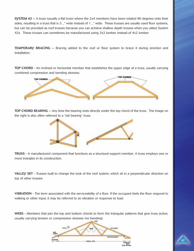
TOP CHORD - An inclined or horizontal member that establishes the upper edge of a truss, usually carrying
combined compression and bending stresses.
TOP CHORD BEARING – Any time the bearing rests directly under the top chord of the truss. The image on
the right is also often referred to a “tail bearing” truss.
TRUSS - A manufactured component that functions as a structural support member. A truss employs one or
more triangles in its construction.
VALLEY SET - Trusses built to change the look of the roof system, which sit in a perpendicular direction on
top of other trusses.
VIBRATION - The term associated with the serviceability of a floor. If the occupant feels the floor respond to
walking or other input, it may be referred to as vibration or response to load.
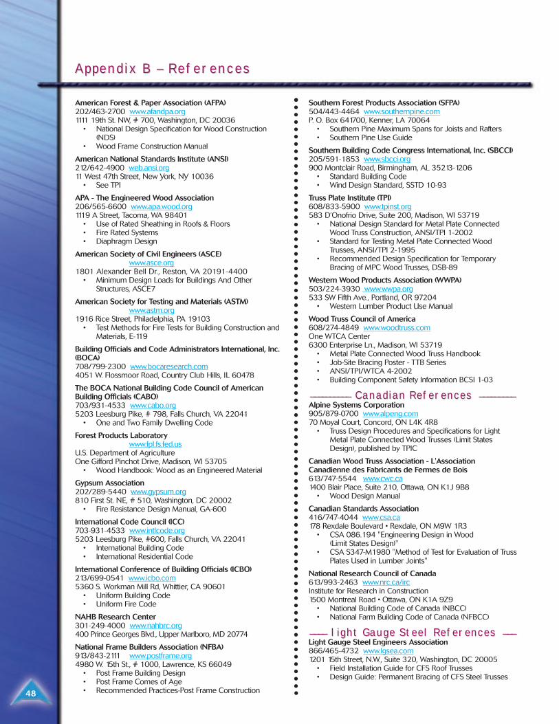
WEBS - Members that join the top and bottom chords to form the triangular patterns that give truss action,
usually carrying tension or compression stresses (no bending).
American Forest & Paper Association (AFPA) 202/463-2700 www.afandpa.org1111 19th St. NW, # 700, Washington, DC 20036
• National Design Specification for Wood Construction(NDS)
• Wood Frame Construction Manual
American National Standards Institute (ANSI) 212/642-4900 web.ansi.org11 West 47th Street, New York, NY 10036
• See TPI
APA - The Engineered Wood Association206/565-6600 www.apa.wood.org1119 A Street, Tacoma, WA 98401
• Use of Rated Sheathing in Roofs & Floors• Fire Rated Systems• Diaphragm Design
American Society of Civil Engineers (ASCE)www.asce.org
1801 Alexander Bell Dr., Reston, VA 20191-4400• Minimum Design Loads for Buildings And Other
Structures, ASCE7
American Society for Testing and Materials (ASTM)www.astm.org
1916 Rice Street, Philadelphia, PA 19103• Test Methods for Fire Tests for Building Construction and
Materials, E-119
Building Officials and Code Administrators International, Inc.(BOCA)708/799-2300 www.bocaresearch.com4051 W. Flossmoor Road, Country Club Hills, IL 60478
The BOCA National Building Code Council of AmericanBuilding Officials (CABO)703/931-4533 www.cabo.org5203 Leesburg Pike, # 798, Falls Church, VA 22041
• One and Two Family Dwelling Code
Forest Products Laboratorywww.fpl.fs.fed.us
U.S. Department of AgricultureOne Gifford Pinchot Drive, Madison, WI 53705
• Wood Handbook: Wood as an Engineered Material
Gypsum Association 202/289-5440 www.gypsum.org810 First St. NE, # 510, Washington, DC 20002
• Fire Resistance Design Manual, GA-600
International Code Council (ICC)703-931-4533 www.intlcode.org5203 Leesburg Pike, #600, Falls Church, VA 22041
• International Building Code• International Residential Code
International Conference of Building Officials (ICBO) 213/699-0541 www.icbo.com5360 S. Workman Mill Rd, Whittier, CA 90601
• Uniform Building Code• Uniform Fire Code
NAHB Research Center301-249-4000 www.nahbrc.org400 Prince Georges Blvd., Upper Marlboro, MD 20774
National Frame Builders Association (NFBA)913/843-2111 www.postframe.org4980 W. 15th St., # 1000, Lawrence, KS 66049
• Post Frame Building Design• Post Frame Comes of Age• Recommended Practices-Post Frame Construction
Southern Forest Products Association (SFPA) 504/443-4464 www.southernpine.comP. O. Box 641700, Kenner, LA 70064
• Southern Pine Maximum Spans for Joists and Rafters• Southern Pine Use Guide
Southern Building Code Congress International, Inc. (SBCCI)205/591-1853 www.sbcci.org900 Montclair Road, Birmingham, AL 35213-1206
• Standard Building Code• Wind Design Standard, SSTD 10-93
Truss Plate Institute (TPI)608/833-5900 www.tpinst.org583 D’Onofrio Drive, Suite 200, Madison, WI 53719
• National Design Standard for Metal Plate ConnectedWood Truss Construction, ANSI/TPI 1-2002
• Standard for Testing Metal Plate Connected WoodTrusses, ANSI/TPI 2-1995
• Recommended Design Specification for TemporaryBracing of MPC Wood Trusses, DSB-89
Western Wood Products Association (WWPA)503/224-3930 www.wwpa.org533 SW Fifth Ave., Portland, OR 97204
• Western Lumber Product Use Manual
Wood Truss Council of America608/274-4849 www.woodtruss.comOne WTCA Center6300 Enterprise Ln., Madison, WI 53719
• Metal Plate Connected Wood Truss Handbook• Job-Site Bracing Poster - TTB Series• ANSI/TPI/WTCA 4-2002• Building Component Safety Information BCSI 1-03
_____________ _______ Canadian ReferCanadian References ences __________________Alpine Systems Corporation905/879-0700 www.alpeng.com70 Moyal Court, Concord, ON L4K 4R8
• Truss Design Procedures and Specifications for LightMetal Plate Connected Wood Trusses (Limit StatesDesign), published by TPIC
Canadian Wood Truss Association - L'AssociationCanadienne des Fabricants de Fermes de Bois613/747-5544 www.cwc.ca1400 Blair Place, Suite 210, Ottawa, ON K1J 9B8
• Wood Design Manual
Canadian Standards Association416/747-4044 www.csa.ca178 Rexdale Boulevard • Rexdale, ON M9W 1R3
• CSA 086.194 "Engineering Design in Wood (Limit States Design)"
• CSA S347-M1980 "Method of Test for Evaluation of TrussPlates Used in Lumber Joints"
National Research Council of Canada613/993-2463 www.nrc.ca/ircInstitute for Research in Construction1500 Montreal Road • Ottawa, ON K1A 9Z9
• National Building Code of Canada (NBCC)• National Farm Building Code of Canada (NFBCC)
____ ____ light Gauge Steel Referlight Gauge Steel References ences ______Light Gauge Steel Engineers Association866/465-4732 www.lgsea.com1201 15th Street, N.W., Suite 320, Washington, DC 20005
• Field Installation Guide for CFS Roof Trusses• Design Guide: Permanent Bracing of CFS Steel Trusses
Appendix B – ReferAppendix B – Referencesences
48