Embed Size (px)
Citation preview
Good Practice Guide & the Residual Stress Working Group
Tony Fry
National Physical Laboratory
BSSM Workshop : The Measurement of Residual Stress using Diffraction Methods, 14th February 2007
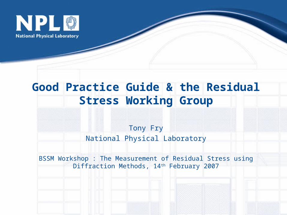
The Good Practice Guide – Where did it all start?
• 1999 – Characterisation and Performance of Materials programme included a project on “The Measurement of Residual Stresses in Components”
• 5 main tasks
– Review current methods
– Assess current methods via a round robin exercise
– Examine the accuracy of current methods
– Case studies
– Standardisation and Good Practice
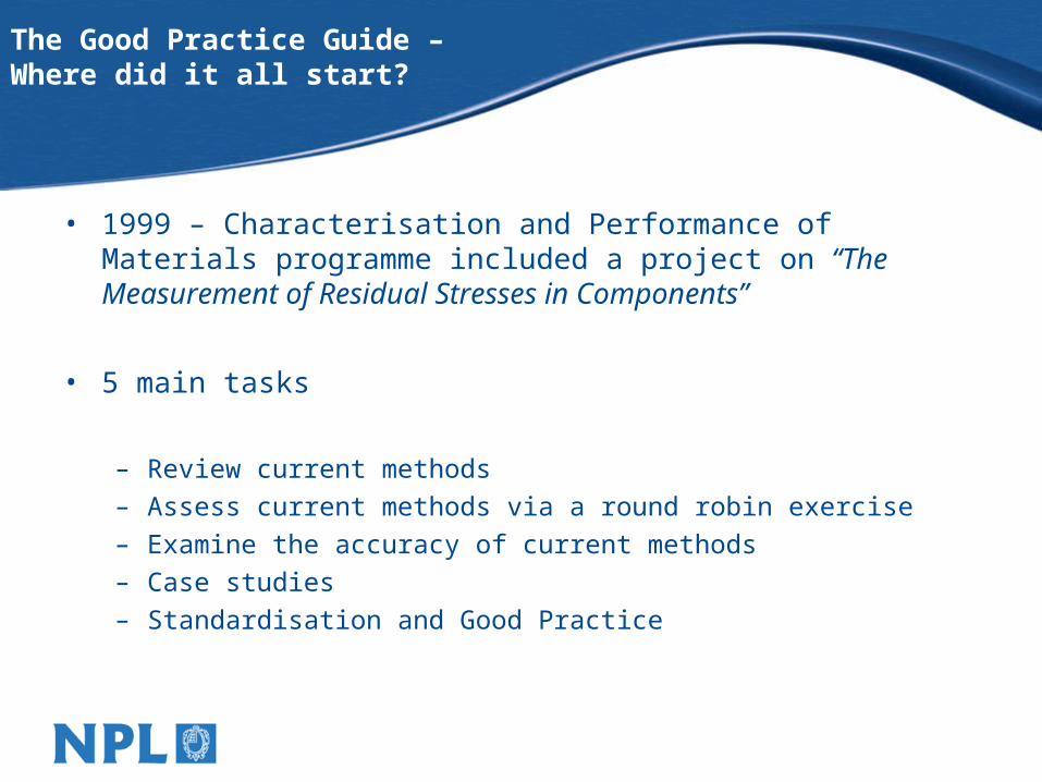
The Good Practice Guide – Was not written in isolation.
Industrial Advisory Group (1999)
• AEA Technology
• Airbus UK
• Alcan
• Alcoa Europe
• British Energy
• Corus
• Dana Glacier Vandervell Bearings
• DERA
• HEXMAT Materials Consultancy
• Imperial College
• Metal Improvement Co
• MMSC
• Powdrex
• Powdrex• Praxair• Quotec• Rolls-Royce• Rolls-Royce Marine • Rutherford Appleton • The Open University • Salford University• Stresscraft• Stresstech• Thin Film Solutions• TWI• UCL• University of Bristol• University of Newcastle
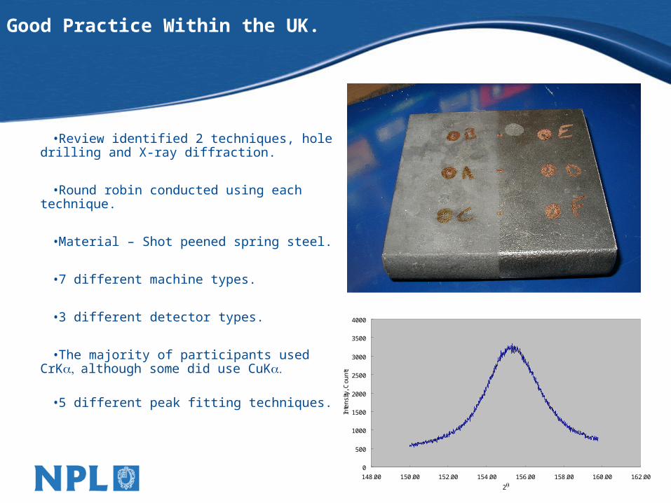
Good Practice Within the UK.
•Review identified 2 techniques, hole drilling and X-ray diffraction.
•Round robin conducted using each technique.
•Material – Shot peened spring steel.
•7 different machine types.
•3 different detector types.
•The majority of participants used CrKalthough some did use CuK
•5 different peak fitting techniques.
0
500
1000
1500
2000
2500
3000
3500
4000
148.00 150.00 152.00 154.00 156.00 158.00 160.00 162.00
2
Inte
nsi
ty, C
ou
nts
Good Practice Within the UK.
-650
-600
-550
-500
-450
-400
-350
-300
-250
A B C D E F G H I J K
Laboratory
No
rma
l Str
ess
, MP
a
Position D
Position E
Position F
NPL Pos D
-650
-600
-550
-500
-450
-400
-350
-300
-250
A B C D E F G H I J K
Laboratory
No
rma
l Str
ess
, MP
a
Position D
Position E
Position F
NPL Pos D

Good Practice Within the UK.
-700
-650
-600
-550
-500
-450
-400
-350
-300
-250
A B C D E F G H I J K
Laboratory
No
rmal
Str
ess,
MP
a
Position D
Position E
Position F
NPL Pos D
We all agreed, why write a Good Practice Guide?
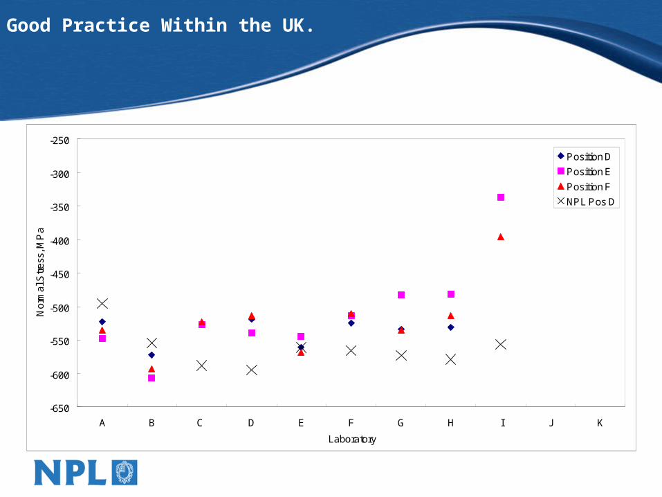
• The round robin showed that on the whole the measurements were in agreement and that everyone was doing the right things.
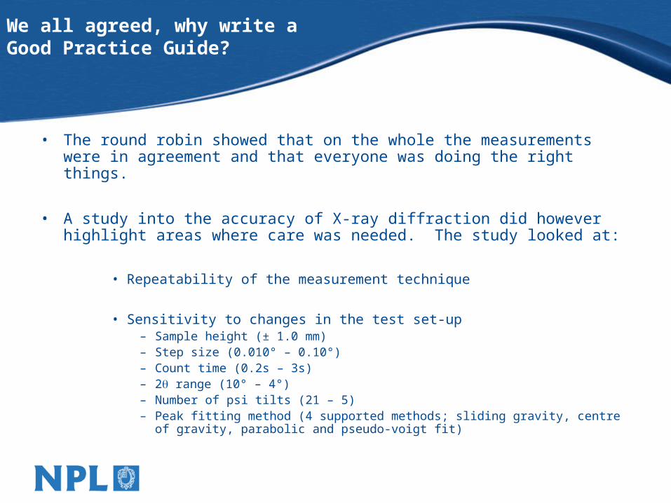
• A study into the accuracy of X-ray diffraction did however highlight areas where care was needed. The study looked at:
• Repeatability of the measurement technique
• Sensitivity to changes in the test set-up– Sample height (± 1.0 mm)– Step size (0.010° – 0.10°)– Count time (0.2s – 3s)– 2 range (10° – 4°)– Number of psi tilts (21 – 5)– Peak fitting method (4 supported methods; sliding gravity, centre of gravity,
parabolic and pseudo-voigt fit)
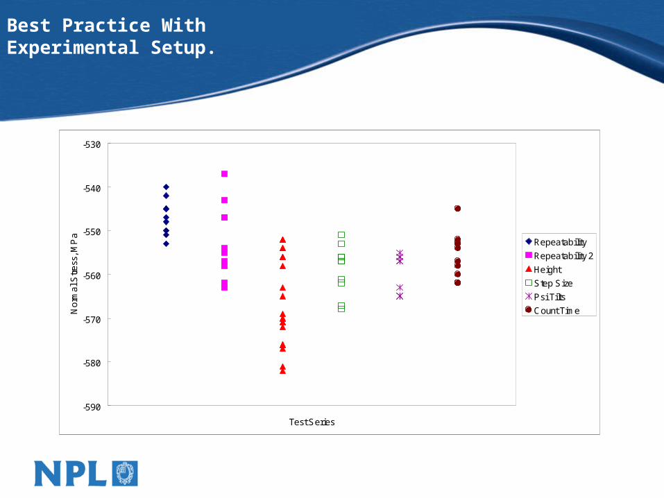
Best Practice With Experimental Setup.
-590
-580
-570
-560
-550
-540
-530
Test Series
No
rma
l Str
ess
, MP
a
Repeatability
Repeatability 2
Height
Step Size
Psi Tilts
Count Time
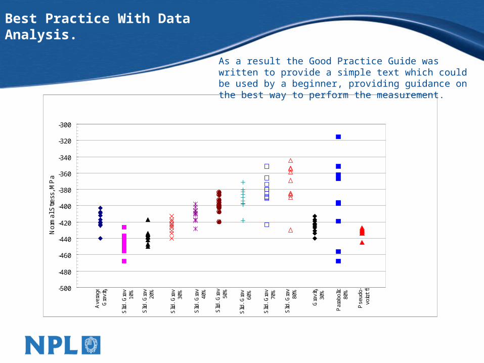
Best Practice With Data Analysis.
-500
-480
-460
-440
-420
-400
-380
-360
-340
-320
-300
No
rma
l Str
ess
, MP
a
Ave
rage
G
ravi
ty
Slid
. G
rav.
10
%
Slid
. G
rav.
20
%
Slid
. G
rav.
30
%
Slid
. G
rav.
40
%
Slid
. G
rav.
50
%
Slid
. G
rav.
60
%
Slid
. G
rav.
70
%
Slid
. G
rav.
80
%
Gra
vity
30
%
Par
abol
ic
80%
Pse
udo-
voig
t fit
As a result the Good Practice Guide was written to provide a simple text which could be used by a beginner, providing guidance on the best way to perform the measurement.
The Good Practice Guide – Written by users, for users.
• NPL Good Practice Guide No. 52 – Determination of Residual Stresses by X-ray Diffraction.
• Authored by experts from the Open University, MMSC, QinetiQ, Stresstech and NPL, with steer from the XRD focus group established as part of this project.
• Scope - The recommendations are meant for stress analysis where only the peak shift is determined. If a full triaxial analysis of stress is performed, using a stress-free reference, then the absolute peak location has to be determined. However, such an analysis is beyond the scope of this Guide, which assumes that measurements are made with the assumption that the stress normal to the surface is zero i.e. plane stress conditions, and so a full triaxial analysis is not required.
The Good Practice Guide – Contents.
• Principles
• Apparatus – Lab based & Portable
• Radiation Selection – Fluorescence, Choice of plane…
• Specimen Issues – Grain size, roughness, coatings…
• Measurement Procedure – Measurement directions & parameters, non-standard samples, data analysis…
• Reporting of Results
• Measurement Uncertainty – Sources, evaluation…
• Options for Data Analysis
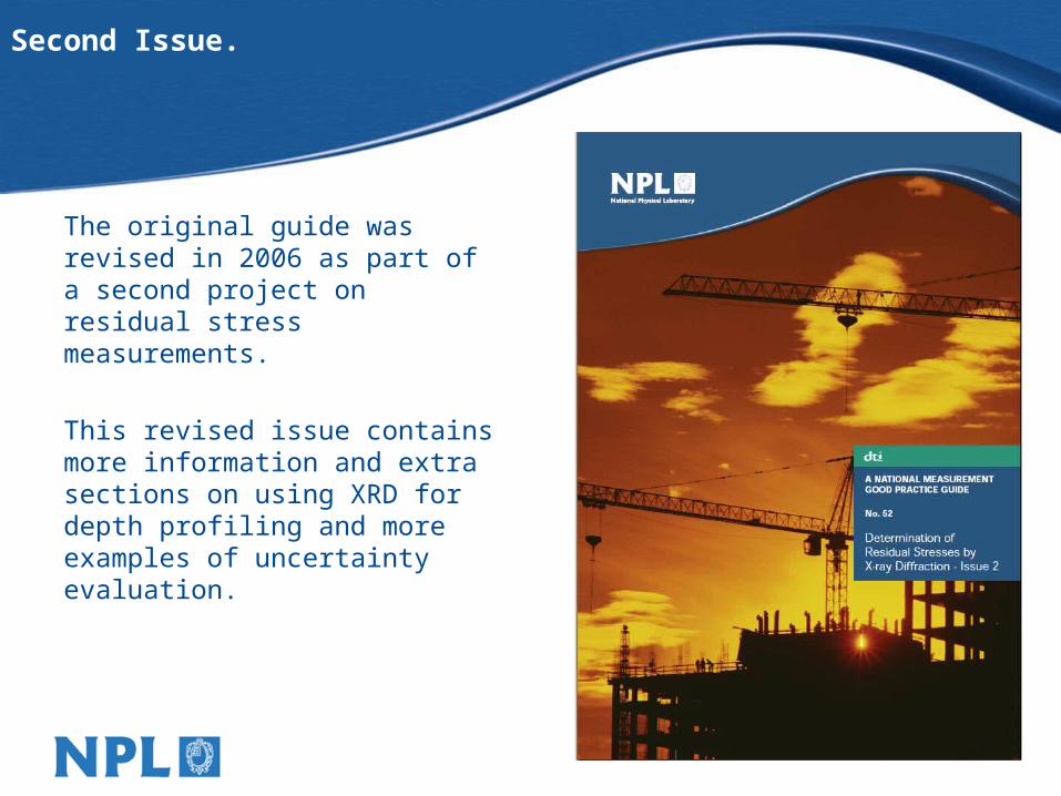
Second Issue.
The original guide was revised in 2006 as part of a second project on residual stress measurements.
This revised issue contains more information and extra sections on using XRD for depth profiling and more examples of uncertainty evaluation.
-60
-40
-20
0
20
40
60
80
100
120
-50 0 50 100 150 200
Depth, m
Re
sid
ua
l Str
ess
, MP
a
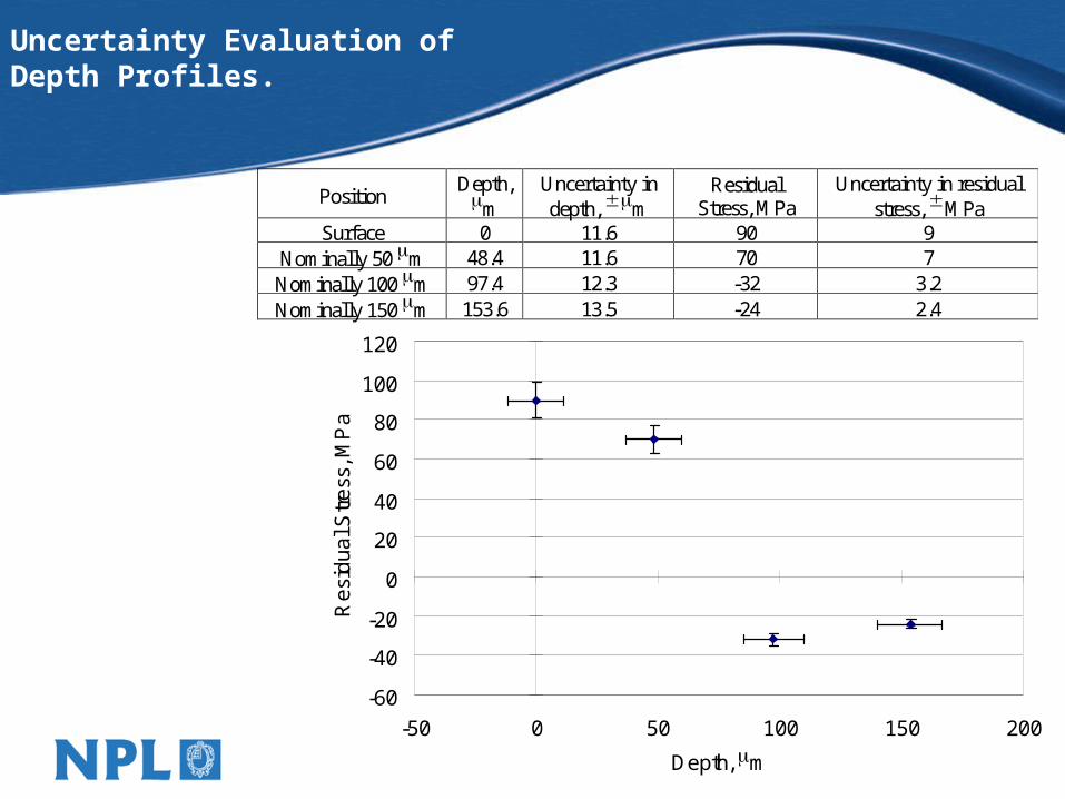
Uncertainty Evaluation of Depth Profiles.
Position Depth, m
Uncertainty in depth, m
Residual Stress, MPa
Uncertainty in residual stress, MPa
Surface 0 11.6 90 9 Nominally 50 m 48.4 11.6 70 7
Nominally 100 m 97.4 12.3 -32 3.2 Nominally 150 m 153.6 13.5 -24 2.4
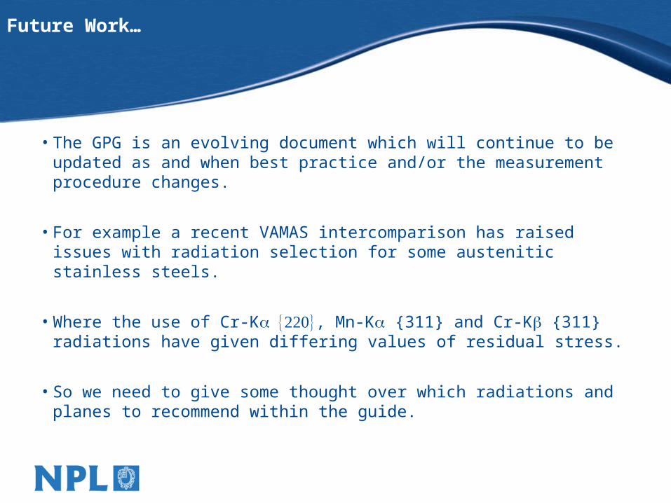
Future Work…
• The GPG is an evolving document which will continue to be updated as and when best practice and/or the measurement procedure changes.
• For example a recent VAMAS intercomparison has raised issues with radiation selection for some austenitic stainless steels.
• Where the use of Cr-K, Mn-K {311} and Cr-K {311} radiations have given differing values of residual stress.
• So we need to give some thought over which radiations and planes to recommend within the guide.
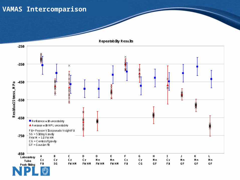
VAMAS Intercomparison
Repeatabilty Results
-850
-750
-650
-550
-450
-350
-250
LaboratoryTube
Peak fitting
Res
idu
al S
tres
s, M
Pa
Reference with uncertainty
Average with NPL uncertainty
LMnGF
KMnGF
JMnGF
ICrFit
HMnGF
GCrCG
ACrFit
FCrFit
EMnFWHM
DMnFWHM
DCrFWHM
CCrFWHM
BCrSG
Fit = Peason VII or pseudo Voight FitSG = Sliding GravityFHWM = 1/2 FWHMCG = Center of gravityGF = Gausian fit
Input into European Standardisation.
Standardisation
• Current activities within Europe (CEN TC138 WG10) to produce a suite of standards for X-ray Powder Diffraction, which includes residual stress measurement using XRD.
• The NPL Good Practice Guide has been used as the basis of the UK contribution to the European Standard.
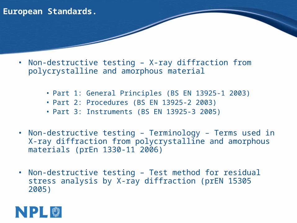
European Standards.
• Non-destructive testing – X-ray diffraction from polycrystalline and amorphous material
• Part 1: General Principles (BS EN 13925-1 2003)• Part 2: Procedures (BS EN 13925-2 2003)• Part 3: Instruments (BS EN 13925-3 2005)
• Non-destructive testing – Terminology – Terms used in X-ray diffraction from polycrystalline and amorphous materials (prEn 1330-11 2006)
• Non-destructive testing – Test method for residual stress analysis by X-ray diffraction (prEN 15305 2005)
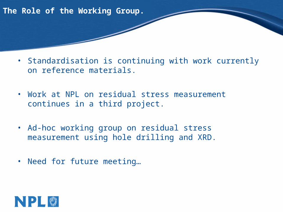
The Role of the Working Group.
• Standardisation is continuing with work currently on reference materials.
• Work at NPL on residual stress measurement continues in a third project.
• Ad-hoc working group on residual stress measurement using hole drilling and XRD.
• Need for future meeting…
![[PPT]PowerPoint Presentation - BSSM - Stress and strain ... presentations/BSSM... · Web viewGood Practice Guide & the Residual Stress Working Group Tony Fry National Physical Laboratory](https://img.dokumen.tips/doc/110x75/5af1f0047f8b9abc788f12b7/pptpowerpoint-presentation-bssm-stress-and-strain-presentationsbssmweb.jpg)