Embed Size (px)
Citation preview

Installation and Operation ManualX -TMF-5964-5850EM-MFC-engPart Number: 541B121AHGNovember, 2008 Brooks® Models 5964, 5850EM
Brooks® Models 5964, 5850EMMass Flow Controllers
Model 5850EMMass Flow Controller
with D-Connector
Model 5850EM DownportedMass Flow Controller
with Card Edge
Model 5964Mass Flow Controller
with D-Connector

Installation and Operation ManualX -TMF-5964-5850EM-MFC-eng
Part Number:541B121AHGNovember, 2008Brooks® Models 5964, 5850EM
ESD (Electrostatic Discharge)
Essential InstructionsRead this page before proceeding!
Brooks Instrument designs, manufactures and tests its products to meet many national and international standards. Becausethese instruments are sophisticated technical products, you must properly install, use and maintain them to ensure theycontinue to operate within their normal specifications. The following instructions must be adhered to and integrated into yoursafety program when installing, using and maintaining Brooks Products.• Read all instructions prior to installing, operating and servicing the product. If this instruction manual is not the correct
manual, please see back cover for local sales office contact information. Save this instruction manual for future reference.• If you do not understand any of the instructions, contact your Brooks Instrument representative for clarification.• Follow all warnings, cautions and instructions marked on and supplied with the product.• Inform and educate your personnel in the proper installation, operation and maintenance of the product.• Install your equipment as specified in the installation instructions of the appropriate instruction manual and per applicable
local and national codes. Connect all products to the proper electrical and pressure sources.• To ensure proper performance, use qualified personnel to install, operate, update, program and maintain the product.• When replacement parts are required, ensure that qualified people use replacement parts specified by Brooks Instrument.
Unauthorized parts and procedures can affect the product's performance and place the safe operation of your process atrisk. Look-alike substitutions may result in fire, electrical hazards or improper operation.
• Ensure that all equipment doors are closed and protective covers are in place, except when maintenance is beingperformed by qualified persons, to prevent electrical shock and personal injury.
Pressure Equipment Directive (PED)All pressure equipment with an internal pressure greater than 0.5 bar (g) and a size larger than 25mm or 1" (inch) falls under thePressure Equipment Directive (PED). The Directive is applicable within the European Economic Area (EU plus Norway, Icelandand Liechtenstein). Pressure equipment can be traded freely within this area once the PED has been complied with.• Section 1 of this manual contains important safety and operating instructions related to the PED directive.• Meters described in this manual are in compliance with EN directive 97/23/EC module H Conformity Assessment.• All Brooks Instrument Flowmeters fall under fluid group 1.• Meters larger than 25mm or 1" (inch) are in compliance with category I, II, III of PED.• Meters of 25mm or 1" (inch) or smaller are Sound Engineering Practice (SEP).
Handling Procedure:1. Power to unit must be removed.2. Personnel must be grounded, via a wrist strap or other safe, suitable means before any printed circuit card or other internal
device is installed, removed or adjusted.3. Printed circuit cards must be transported in a conductive container. Boards must not be removed from protective enclosure
until immediately before installation. Removed boards must immediately be placed in protective container for transport,storage or return to factory.
CommentsThis instrument is not unique in its content of ESD (electrostatic discharge) sensitive components. Most modern electronicdesigns contain components that utilize metal oxide technology (NMOS, SMOS, etc.). Experience has proven that even smallamounts of static electricity can damage or destroy these devices. Damaged components, even though they appear to functionproperly, exhibit early failure.

Installation and Operation ManualX -TMF-5964-5850EM-MFC-engPart Number: 541B121AHGNovember, 2008 Brooks® Models 5964, 5850EM
Dear Customer,We appreciate this opportunity to service your flow measurement and control requirements with a BrooksInstrument device. Every day, flow customers all over the world turn to Brooks Instrument for solutions to theirgas and liquid low-flow applications. Brooks provides an array of flow measurement and control products forvarious industries from biopharmaceuticals, oil and gas, fuel cell research and chemicals, to medical devices,analytical instrumentation, semiconductor manufacturing, and more.
The Brooks product you have just received is of the highest quality available, offering superior performance,reliability and value to the user. It is designed with the ever changing process conditions, accuracy requirementsand hostile process environments in mind to provide you with a lifetime of dependable service.
We recommend that you read this manual in its entirety. Should you require any additional information concerningBrooks products and services, please contact your local Brooks Sales and Service Office listed on the back coverof this manual or visit www.BrooksInstrument.com
Yours sincerely,Brooks Instrument

Installation and Operation ManualX -TMF-5964-5850EM-MFC-eng
Part Number:541B121AHGNovember, 2008Brooks® Models 5964, 5850EM
THIS PAGE WASINTENTIONALLY
LEFT BLANK

i
Brooks® Models 5964, 5850EM
ContentsInstallation and Operation ManualX -TMF-5964-5850EM-MFC-engPart Number: 541B121AHGNovember, 2008
Paragraph PageNumber Number
Section 1 Introduction1-1 How to Use This Manual ............................................................................................................ 1-11-2 Description ................................................................................................................................. 1-11-3 Specifications ............................................................................................................................. 1-2
Section 2 Installation2-1 General ...................................................................................................................................... 2-12-2 Receipt of Equipment ................................................................................................................. 2-12-3 Recommended Storage Practice ............................................................................................... 2-12-4 Return Shipment ........................................................................................................................ 2-22-5 Transit Precaution ...................................................................................................................... 2-22-6 Removal from Storage ............................................................................................................... 2-22-7 In-Line Filter ............................................................................................................................... 2-32-8 Installation .................................................................................................................................. 2-32-9 Electrical Interface ...................................................................................................................... 2-42-10 Operation Procedure .................................................................................................................. 2-5
Section 3 Operation3-1 Overview .................................................................................................................................... 3-13-2 Connections and Controls .......................................................................................................... 3-13-3 Theory of Operation ................................................................................................................... 3-43-4 Features ..................................................................................................................................... 3-63-5 Adjustment Potentiometers ....................................................................................................... 3-153-6 Zero Adjustment ........................................................................................................................ 3-163-7 Calibration Procedure ............................................................................................................... 3-173-8 Response Adjustment ............................................................................................................... 3-22
Section 4 Maintenance4-1 Overview .................................................................................................................................... 4-14-2 Troubleshooting .......................................................................................................................... 4-24-3 Gas Conversion Factors ............................................................................................................ 4-64-4 Orifice Sizing ............................................................................................................................. 4-104-5 Restrictor Sizing ........................................................................................................................ 4-15
Section A CE CertificateCE Certificate of Mass Flow Equipment ................................................................................................A-1
Warranty, Local Sales/Service Contact Information ....................................................................... Back Cover

ii
Brooks® Models 5964, 5850EM
Contents Installation and Operation ManualX -TMF-5964-5850EM-MFC-eng
Part Number:541B121AHGNovember, 2008
FiguresFigure PageNumber Number1-1 MFC/MFM Dimensional Drawing for Model 5964/5850EM
with D-Connector and VCR Fittings ........................................................................................ 1-51-2 MFC/MFM Dimensional Drawing for Model 5964/5850EM
with Card Edge and VCR Fittings ............................................................................................ 1-61-3 MFC/MFM Dimensional Drawing for Model 5964/5850EM Downported with D-Connector .... 1-71-4 MFC/MFM Dimensional Drawing for Model 5964/5850EM Downported with Card Edge ....... 1-82-1 Card Edge Connector ............................................................................................................. 2-62-2 20 Pin Card Edge Connector Ribbon Cable Hookup Diagram ................................................ 2-72-3 D-Connector Shielded Cable Hookup Diagram - Voltage I/O Version ..................................... 2-62-4 D-Connector Shielded Cable Hookup Diagram - Current I/O Version ..................................... 2-82-5 Maximum Allowable Loop Resistance-Current I/O version ..................................................... 2-82-6 Common Electrical Hookups Current I/O version ................................................................... 2-93-1 Model 5964/5850EM Components .......................................................................................... 3-23-2 Externaslly Accessible Adjustments ........................................................................................ 3-33-3 Flow Sensor Operational Diagram (VCRTM End Connections Shown) .................................... 3-43-4 Flow Controller System Block Diagram ................................................................................... 3-43-5 Enhanced Response 20 Pin Card Edge PC Board Jumper location and Function ................. 3-63-6 Standard Response 20 Pin D-Connector PC Board Jumper location and Function ................ 3-73-7 Enhanced Response 15 Pin D-Connector PC Board Jumper location and Function .............. 3-83-8 Standard Response 15 Pin D-Connector PC Board Jumper location and Function ................ 3-93-9 Current I/O Version PC Board Jumper Location and Function .............................................. 3-103-10 Command Steps, Soft Start Disabled .................................................................................... 3-113-11 100% Command Steps, Soft Start Enabled ........................................................................... 3-113-12 Adjustment Potentiometer Location ...................................................................................... 3-143-13 Bench Troubleshooting Circuit .............................................................................................. 3-163-14 Response Adjustment ........................................................................................................... 3-224-1 Model 5964/5850EM Orifice Sizing Nomograph ................................................................... 4-114-2 Example Nomograph ............................................................................................................ 4-14
TablesTable PageNumber Number2-1 Recommended Filter Size .......................................................................................................... 2-33-1 Cables, calibration Covers and PC Boards for Model 5964/5850EM ......................................... 3-34-1 Bench Troubleshooting .............................................................................................................. 4-44-2 Sensor Troubleshooting ............................................................................................................. 4-54-3 Conversion Factors (Nitrogen Base) .......................................................................................... 4-74-4 Model 5964/5850EM Standard Restrictors ................................................................................ 4-16

1-1
Brooks® Models 5964, 5850EM
Section 1 IntroductionInstallation and Operation ManualX-TMF-5964-5850EM-MFC-engPart Number: 541B121AHGNovember, 2008
1-1 How to Use This Manual
This instruction manual is intended to provide the user with all theinformation necessary to install, operate and maintain theBrooks® Models 5964 and 5850EM
This manual is organized into the following sections:
Section 1. IntroductionSection 2. InstallationSection 3. OperationSection 4. MaintenanceSection A CE CertificationsBack Cover Warranty, Local Sales/Service Contact Information
1-2 Description
The Brooks Models 5964 and 5850EM Mass Flow Controllers is used ingas flow handling systems where very low leakage and high performanceare required. The Models 5964 and 5850EM incorporates metal seals orwelded joints, insuring leak integrity for high purity and high vacuumapplications. Reducing the amount of internal threads makes the designless prone to system contamination. The control electronics and flowsensor designs utilized in the Models 5964 and 5850EM have been well-proven in precision gas delivery systems. Standard features include:
• High leak integrity (less than 10-10 atm-cc/sec He)• Enhanced process (7 Ra) internal surface finish (Optional 5850EM)• Electropolished wetted surfaces (Optional 5850EM)• High purity VAR 316L Stainless Steel• All metal seals• Particulate free• Wide flow range (0.06 sccm through 30,000 sccm)• Insensitive to mounting attitude• Negligible flow overshoot/undershoot• Fast response control permits rapid gas settling times with minimal
over/undershoot. Refer to Figure 1-1.• Helium leak check ports• Class 100 Clean Room assembly and calibration (Optional 5850EM)• Available with all popular process connections

1-2
Brooks® Models 5964, 5850EM
Section 1 Introduction Installation and Operation ManualX-TMF-5964-5850EM-MFC-eng
Part Number: 541B121AHGNovember, 2008
1-3 Specifications
PERFORMANCE CHARACTERISTICS:Flow Ranges*Any range from 0 - 3 sccm to 0 - 30,000 sccm Nitrogen equivalent. Lowerflows available, consult factory.*Standard: 0°C and 101 kPa (760 Torr). Per SEMI Guideline E12-96.
Control Range2 - 100% with elastomeric valve seat3 - 100% with metal or Teflon® valve seat
Accuracy1% Full Scale including linearity, at calibration conditions1.5% Full Scale including linearity, for flow ranges greater than 20 slpm
Repeatability0.25% of rate
Settling TimeModel 5964: Enhanced response PCB's less than 1 sec to within 2% ofFull Scale of final value for a 0-100% command step with Normally ClosedValve. (Optional on 5850EM).Model 5850EM: Less than 3 seconds to within 2% of Full Scale of finalvalue for a 0-100% command step with Normally Closed Valve.**Per SEMI Guideline E17-91.
Mounting Attitude SensitivityAvailable in any position0.5% maximum full scale deviation after rezeroing
Temperature SensitivityZero: Less than ±0.075% full scale per °CSpan: Less than ±1.0% full scale shift over 10-50°C range
Pressure Equipment Directive (PED) 97/23/ECSound Engineering Practice
Pressure Sensitivity0.008% per psi Nitrogen
RATINGS:
Operating Pressure1,500 psi (10.342 MPa) max.Note: 150 psi for enhanced response500 psi for stainless steel fasteners option.

1-3
Brooks® Models 5964, 5850EM
Section 1 IntroductionInstallation and Operation ManualX-TMF-5964-5850EM-MFC-engPart Number: 541B121AHGNovember, 2008
Differential PressureValve orifice sized for any pressure drop between 5 to 50 psi (Minimumpressure drop depends on gas and range).
Ambient Temperature LimitsOperating: 40°F to 150°F (5°C to 65°C)Non-Operating: -13°F to 212°F (-25°C to 100°C)
Leak IntegrityInboard to outboard 1 x 10⁻¹⁰ atm. cc/sec. Helium max.
PHYSICAL CHARACTERISTICS:
Materials of Construction316L VAR (Vacuum Arc Remelt), 316L, and high alloy ferritic stainless
steel.External seals: Nickel.Internal seals: Nickel.Valve Seat: 316L, Viton® fluoroelastomers, Buna-N, Kalrez® or Teflon®.
DimensionsRefer to Figures 1-1 thru 1-4
Process Connections1/4" Tube VCRTM
Downport C-SealDownport W-Seal
Surface Finish5850EM: 32Ra, Passivated5964: 7Ra, Electropolished
ELECTRICAL CHARACTERISTICS:
Electrical ConnectionsCard Edge: 30 microinch gold over low stress nickel-plated copperD-Connector: 15 Pin (DA-15P)
Command InputVoltage Option: 0-5 Vdc (Input resistance 40 k ohm min.)Current Option: 4-20 mAdc (Input resistance 75 ohm)
Output SignalVoltage Option: 0 to 5 Vdc into 2,000 ohms minimumCurrent Option: Jumper selectable 4-20 mAdc or 0-20 mAdc, refer toFigure 2-6 for maximum total loop resistance
1-4
Brooks® Models 5964, 5850EM
Section 1 Introduction Installation and Operation ManualX-TMF-5964-5850EM-MFC-eng
Part Number: 541B121AHGNovember, 2008
ELECTRICAL CHARACTERISTICS (continued):
5 Volt Reference Output5 Volts, ±0.01 Vdc into 2,000 ohms minimum
Power RequirementsVoltage Option:N.C. Valve (or N.O. Valve with flow less than 2.5 slpm):
3.25 watts max., + 15 Vdc @ 35 mA -15 Vdc @ 180 mAN.O. Valve with flow rate greater than 2.5 slpm:
10.5 watts max.,+15 Vdc @ 350 mA, -15 Vdc @ 350 mA
Current Option:+15 Vdc to +28 Vdc: 3.68 Watts min, +15 Vdc @ 245 mA
10.36 Watts max., +28 Vdc @ 370 mA
Power Supply SensitivityNone within ±5% of specified voltage (See Power Requirements)

1-5
Brooks® Models 5964, 5850EM
Section 1 IntroductionInstallation and Operation ManualX-TMF-5964-5850EM-MFC-engPart Number: 541B121AHGNovember, 2008
Figure 1-1 MFC/MFM Dimensional Drawing for Model 5964/5850EM with D-Connector and VCR Fittings

1-6
Brooks® Models 5964, 5850EM
Section 1 Introduction Installation and Operation ManualX-TMF-5964-5850EM-MFC-eng
Part Number: 541B121AHGNovember, 2008
Figure 1-2 MFC/MFM Dimensional Drawing for Model 5964/5850EM with Card Edge and VCR Fittings

1-7
Brooks® Models 5964, 5850EM
Section 1 IntroductionInstallation and Operation ManualX-TMF-5964-5850EM-MFC-engPart Number: 541B121AHGNovember, 2008
Figure 1-3 MFC/MFM Dimensional Drawing for Model 5964/5850EM Downported with D-Connector

1-8
Brooks® Models 5964, 5850EM
Section 1 Introduction Installation and Operation ManualX-TMF-5964-5850EM-MFC-eng
Part Number: 541B121AHGNovember, 2008
Figure 1-4 MFC/MFM Dimensional Drawing for Model 5964/5850EM Downported with Card Edge

2-1
Brooks® Models 5964, 5850EM
Section 2 InstallationInstallation and Operation ManualX-TMF-5964-5850EM-MFC-engPart Number: 541B121AHGNovember, 2008
2-1 General
This section contains the procedures for the receipt and installation of theinstrument. See Section 1 for dimensional and connection requirements.Do not attempt to start the system until the instrument has beenpermanently installed. It is important that the start-up procedures befollowed in the exact sequence presented.
2-2 Receipt of Equipment
When the instrument is received, the outside packing case should bechecked for damage incurred during shipment. If the packing case isdamaged, the local carrier should be notified at once regarding his liability.A report should be submitted to your nearest Product Service Department.
Brooks Instrument407 W. Vine StreetP.O. Box 903Hatfield, PA 19440 USAToll Free (888) 554-FLOW (3569)Tel (215) 362-3700Fax (215) 362-3745E-mail: [email protected]
Brooks Instrument Brooks InstrumentNeonstraat 3 1-4-4 Kitasuna Koto-Ku6718 WX Ede, Netherlands Tokyo, 136-0073 JapanP.O. Box 428 Tel 011-81-3-5633-71006710 BK Ede, Netherlands Fax 011-81-3-5633-7101Tel 31-318-549-300 Email: [email protected] 31-318-549-309E-mail: [email protected]
Remove the envelope containing the packing list. Carefully remove theinstrument from the packing case. Make sure spare parts are notdiscarded with the packing materials. Inspect for damaged or missingparts.
2-3 Recommended Storage Practice
If intermediate or long-term storage of equipment is required, it isrecommended that the equipment be stored in accordance with thefollowing conditions:a. Within the original shipping container.b. Stored in a sheltered area, preferably a warm, dry, heated warehouse.c. Ambient temperature 21°C (70°F) nominal, 32°C (90°F) maximum,
45°F (7°C) minimum.d. Relative humidity 45% nominal, 60% maximum, 25% minimum.

2-2
Brooks® Models 5964, 5850EM
Section 2 Installation Installation and Operation ManualX-TMF-5964-5850EM-MFC-eng
Part Number: 541B121AHGNovember, 2008
2-4 Return Shipment
Prior to returning any instrument to the factory, contact your nearest Brookslocation for a Return Materials Authorization Number (RMA#). This can beobtained from one of the following locations:
Brooks Instrument407 W. Vine StreetP.O. Box 903Hatfield, PA 19440 USAToll Free (888) 554-FLOW (3569)Tel (215) 362-3700Fax (215) 362-3745E-mail: [email protected]
Brooks Instrument Brooks InstrumentNeonstraat 3 1-4-4 Kitasuna Koto-Ku6718 WX Ede, Netherlands Tokyo, 136-0073 JapanP.O. Box 428 Tel 011-81-3-5633-71006710 BK Ede, Netherlands Fax 011-81-3-5633-7101Tel 31-318-549-300 Email: [email protected] 31-318-549-309E-mail: [email protected]
Instrument must have been purged in accordance with the following:
All flow instruments returned to Brooks requires completion of FormRPR003-1, Brooks Instrument Decontamination Statement, along with aMaterial Safety Data Sheet (MSDS) for the fluid(s) used in the instrument.Failure to provide this information will delay processing by Brookspersonnel. Copies of these forms can be downloaded from the Brookswebsite www.BrooksInstrument.com or are available from any BrooksInstrument location listed above.
2-5 Transit Precautions
To safeguard the instrument against transportation damage, it isrecommended to keep the instrument in its factory container until ready forinstallation.
2-6 Removal from Storage
Upon removal of the instrument from storage, a visual inspection should beconducted to verify its "as-received" condition. If the instrument has beensubject to storage conditions in excess of those recommended (SeeSection 2-3), it should be subjected to a pneumatic pressure test inaccordance with applicable vessel codes.

2-3
Brooks® Models 5964, 5850EM
Section 2 InstallationInstallation and Operation ManualX-TMF-5964-5850EM-MFC-engPart Number: 541B121AHGNovember, 2008
2-7 In-Line Filter
It is recommended that an in-line filter be installed upstream from thecontroller to prevent the possibility of any foreign material entering theflow sensor or control valve. The filtering element should be replacedperiodically or ultrasonically cleaned.
Maximum Flow Rate Recommended Filter100 sccm 1 micron500 sccm 2 micron
1 to 5 slpm 7 micron10 to 30 slpm 15 micron
2-8 Installation
Prior to installation, make certain all piping is clean and free ofobstructions, for tubing installations. Install the piping in such a mannerthat permits easy access to the instrument if it needs to be removed forcleaning or test bench troubleshooting. For surface mount (downported)devices verify that the seal cavities are clean and free of lateralscratches.
When installing the controller, care should be taken that no foreign materials enter the inlet or outlet of the instrument. Do not remove the protective end caps until time of installation.
CAUTION
Recommended installation procedures:a. The Model 5964/5850EM should be located in a clean, dry atmo-
sphere relatively free from shock and vibration.b. Leave sufficient room for access to the electrical components, span
and zero potentiometers.c. Install in such a manner that permits easy removal if the instrument
requires servicing.
When used with a reactive (sometimes toxic gas) contamination or corrosion may occur as a result of plumbing leaks or improper purging. Plumbing should be checked carefully for leaks and the instrument purged with clean, dry N2 before use.
CAUTION
d. The Model 5964/5850EM Mass Flow Controller can be installed inany position. However, mounting in orientations other than theoriginal factory calibration (see calibration data sheet) can result in a0.5% maximum full scale shift after re-zeroing.
Table 2-1 Recommended Filter Size

2-4
Brooks® Models 5964, 5850EM
Section 2 Installation Installation and Operation ManualX-TMF-5964-5850EM-MFC-eng
Part Number: 541B121AHGNovember, 2008
Use caution when installing surface mount (downported) controllers. Most metal seals can not be reused after compression. Follow the seal manufacturers’ recommendations for installation. Tighten the mounting screws in 10 in-lb. increments such that the seal undergoes uniform compression. Final torque values depend on the screw and hardware material and lubrication.
CAUTION
e. The control valve in the Model 5964/5850EM provides precisioncontrol and is not designed for positive shut-off. If positive shut-off isrequired, it is recommended that a separate shut-off valve beinstalled in-line.
2-9 Electrical Interface

2-5
Brooks® Models 5964, 5850EM
Section 2 InstallationInstallation and Operation ManualX-TMF-5964-5850EM-MFC-engPart Number: 541B121AHGNovember, 2008
To insure proper operation, the Model 5964/5850EM must be connectedper Figures 2-1 through 2-6 depending upon the type of printed circuitboard and connector. As a minimum, the following connections must bemade:
Voltage I/O Version Current I/O Version• Chassis Ground • Chassis Ground• Signal Common • Signal Output Return• Signal Output • Voltage or Current• +15 Vdc Supply Signal Output• -15 Vdc Supply • 15-28 Vdc Supply• Command Input • Supply Common• Command Common • Voltage or Current• Supply Common • Voltage or Current• Valve Return (Specific Command Input to applications see below) • Command Return
The Brooks (electric/electronic) equipment bearing the CE mark has been successfully tested to the regulations of the Electro Magnetic Compatibility (EMC directive 89/336/EEC). Special attention is required when selecting the signal cable to be used with CE marked equipment.
Brooks supplies high quality cables which meet the specifications for CE certification. If you provide your own signal cable you should use a cable which is completely screened with a 100% shield. D-Connectors should also be shielded using a metal shield. If applicable, metal cable glands must be used to provide cable screen clamping. The cable screen should be connected to the metal shell or gland and shielded at both ends over 360 degrees. The shield should be terminated to an earth ground. See Appendix A for CE Certification of Mass Flow Equipment.
NOTICE
Note: If older Brooks secondary electronics are used to power and controlthe Model 5964/5850EM, the 5 Volt reference must be enabled. Brookssecondary electronics that require the 5 Volt reference consist of 587x and589x series.
2-10 Operation Procedure
a. Mount the controller in its final orientation.b. Apply power to the controller and allow approximately 45 minutes for
the instrument to warm up and stabilize its temperature.c. Turn on the gas supply.d. Command zero percent (0%) flow and observe the controller’s output
signal. If the output is not zero mVdc (10 mVdc), check for leaks and, ifnone are found, refer to the re-zeroing procedure in Section 3-6.
e. Set the command for the desired flow rate to assume normal operation.Note: If a separate positive shut-off valve is not installed, a flow signalmay result from leak-through. Leak-through is more significant withstainless steel and Teflon valve seats.

2-6
Brooks® Models 5964, 5850EM
Section 2 Installation Installation and Operation ManualX-TMF-5964-5850EM-MFC-eng
Part Number: 541B121AHGNovember, 2008
Pin No. Function Color Code1 Command Common Black2 0-5 Volt Signal Output White3 Not Used/External Valve Return* Red4 Valve Off Green5 +15 Vdc Supply Orange6 -15 Vdc Supply Blue7 Valve Test Point/Purge Wht/Blk8 Command Input Red/Blk9 Supply Common Grn/Blk
10 0-5 Volt Signal Common Org/Blk11 +5 Volt Reference Output Blu/Blk12 Valve Override Blk/Wht13 Not Used Red/Wht14 Chassis Ground Grn/Wht15 Not Used** Blu/Wht
*Jumper Selectable - Refer to Figure 3-7 or 3-8. **Jumper Selectable -Remote Transducer input on standard response PC board only.
Refer to Figure 3-8.
* This pin is used for Valve Common on Unit replacement PC Board.** Remote Transducer In on 3 second response PCB only. Refer to Figure 3-6.*** Jumper selectable. Refer to Figure 3-5 or 3-6.
SL
OT
1 10986
SL
OT
5432 L ABCD
Component Sideof PC Board
EFJK
Non-Component Sideof PC Board
Figure 2-1 Card Edge Connector
Chassis Ground 1 A Command InputFlow Signal Common* 2 B Command Common
Flow Signal Output 3 C Supply Common+15 Vdc Supply 4 D Valve Test Point
Not Used** 5 E Not UsedNot Used 6 F -15Vdc Supply
Slot 7 H SlotNot Used 8 J Not Used
Valve Override 9 K Not Used5V Ref. or Valve Return or Not Used***10 L Valve Off
Figure 2-3 D-Connector Shielded Cable Hookup Diagram - Voltage I/O Versions
1
159
8

2-7
Brooks® Models 5964, 5850EM
Section 2 InstallationInstallation and Operation ManualX-TMF-5964-5850EM-MFC-engPart Number: 541B121AHGNovember, 2008
Figure 2-2 20 Pin Card Edge Connector Ribbon Cable Hookup Diagram
PCB No. Connector Pin No. Function Color Code1 1 Chassis Ground BrownA 2 Command Input Red2 3 0-5 V Signal Common* OrangeB 4 Command Common Yellow3 5 0-5 V Signal Output GreenC 6 Supply Common Blue4 7 +15 Vdc Supply VioletD 8 Valve test Point Gray5 9 Not Used** WhiteE 10 Not Used Black6 11 Not Used BrownF 12 -15 Vdc Input Red7 13 Slot OrangeH 14 Slot Yellow8 15 Not Used GreenJ 16 Not Used Blue9 17 Valve Override VioletK 18 Not Used Gray10 19 +5 V Reference Output or Valve Return*** WhiteL 20 Valve Off Black
*This Pin is used for Valve Common on Unit replacement PC board.**Jumper Selectable Remote Transducer input on standard response PC board only. Refer to Figure 3-6.***Jumper Selectable - Refer to Figure 3-5 or 3-6.

2-8
Brooks® Models 5964, 5850EM
Section 2 Installation Installation and Operation ManualX-TMF-5964-5850EM-MFC-eng
Part Number: 541B121AHGNovember, 2008
POWER SUPPLY VOLTAGE (VOLTS)
100
200
900
1000
700
800
500
600
300
0
14 27262221 2825
400
2423201918171615
TOTA
L L
OO
P R
ES
ISTA
NC
E (
OH
MS
)
ALLOWABLE OPERATING RANGE
Figure 2-5 Maximum Allowable Loop Resistance - Current I/O Version
Figure 2-4 D-Connector Shielded Cable Hookup Diagram - CurrentI/O Version
Pin No. Function Color Code1 Command Return Black2 0-5 Volt Signal Output White3 Not Used Red4 Current Signal Output Green5 +15 to +28 Vdc Supply Orange6 Not Used Blue7 Current Command Input Wht/Blk8 Voltage Command Input Red/Blk9 Supply Common Grn/Blk10 Signal Output Return Org/Blk11 +5 Volt Reference Output Blu/Blk12 Valve Override Blk/Wht13 Not Used Red/Wht14 Chassis Ground Grn/Wht15 Not Used Blu/Wht
1
159
8

2-9
Brooks® Models 5964, 5850EM
Section 2 InstallationInstallation and Operation ManualX-TMF-5964-5850EM-MFC-engPart Number: 541B121AHGNovember, 2008
Figure 2-6 Common Electrical Hookups Current I/O Version
Voltage Output
+
+
+
1
159
8
Power Supply15 - 28 Vdc
CurrentSetpoint
Input
Signal OutputReturn
Current Signal: Setpoint and Output
ComCurrent Output
Note 2
Indicator orReceiver
+
+
+
1
159
8
Power Supply15 - 28 Vdc
VoltageSetpoint
Input
Signal OutputReturn
Voltage Signal: Setpoint and Output
Com
Ret
Ret
Note 2
Indicator orReceiver
V
Notes:1. The returns for the command input and current output are not isolated from power supply common.2. Tie cable shields to ground at one end only.3. Current and voltage outputs may be used simultaneously.

2-10
Brooks® Models 5964, 5850EM
Section 2 Installation Installation and Operation ManualX-TMF-5964-5850EM-MFC-eng
Part Number: 541B121AHGNovember, 2008
THIS PAGE WASINTENTIONALLY
LEFT BLANK

3-1
Brooks® Models 5964, 5850EM
Section 3 OperationInstallation and Operation ManualX-TMF-5964-5850EM-MFC-engPart Number: 541B121AHGNovember, 2008
3-1 Overview
After the flowmeter has been properly installed in the process, it is readyfor operation. When initiating flow, slowly open the valve to avoid a flowsurge.Bypass is a help in bringing the flow on smoothly. Avoid starting apump to supply the flowmeter without the use of a valve upstream of theflowmeter.
This section contains the following information:• Features and Jumper Configurations• Theory of Operation• Adjustment Potentiometers• Calibration and Response Adjustments
3-2 Connections and Controls
Figure 3-1 shows the locations of the Model 5964/5850EM controls andconnections. Figure 3-2 identifies the externally accessible adjustmentpotentiometers located on the inlet side of the instrument.

3-2
Brooks® Models 5964, 5850EM
Section 3 Operation Installation and Operation ManualX-TMF-5964-5850EM-MFC-eng
Part Number: 541B121AHGNovember, 2008
Figure 3-1 Model 5964/5850EM Components
Electronics Cover
Valve CoilAssembly
Valve Connector
OutletConnector
ElectricalInterface
InletConnector
AdjustmentPotentiometers
Tubing Connections
Electronics Cover
Valve CoilAssembly
Valve Connector
ElectricalInterface
AdjustmentPotentiometers
MountingFastener Bore
Downported

3-3
Brooks® Models 5964, 5850EM
Section 3 OperationInstallation and Operation ManualX-TMF-5964-5850EM-MFC-engPart Number: 541B121AHGNovember, 2008
Table 3-1 Cables, Calibration Covers and PC Boards for Model 5964/5850EM
5964/5850EM To Model Cable Type Cable Part Number5 feet 10 feet 25 feet 50 feet
0151E (Panel) Ribbon S124Z469AAA S124Z470AAA S124Z471AAA S124Z472AAACard Open FrameEdge 0151E (Table Top)
0152E Shielded S124Z669AAA S124Z539AAA S124Z562AAA S124Z670AAA0154E
0151E (Panel) Shielded S124Z361AAA S124Z362AAA S124Z363AAA S124Z435AAAD-Connector Open Frame(Voltage I/O) 0151E (Table Top)
0152E Shielded S124Z576AAA S124Z577AAA S124Z578AAA S124Z579AAA0154E
0151i (Panel) Shielded S124Z361AAA S124Z362AAA S124Z363AAA S124Z435AAAD-Connector 0151i (Table Top)(Current I/O) 0152i Shielded S124Z576AAA S124Z577AAA S124Z578AAA S124Z579AAA
0154i
***QTA = Viton, SUA = Buna, TTA = Kalrez
Break Out Board Assembly:Card Edge P/N S273Z649AAAD-Connector P/N S273Z668AAA
Installs directly between mass flow controller andinterconnecting cable. Allows convenient access to all signalsfor easy troubleshooting of the system.
Contains:1 Break Out PC Board1 5 foot Extension Cable1 Terminal PC Board
Calibration Cover:Card Edge P/N 909Z011EADD-Connector P/N 909Z017EAD
Calibration covers reduce the chance of accidental cantact withthe circuit board but allow access for all adjustmentpotentiometers and test points needed for calibration.

3-4
Brooks® Models 5964, 5850EM
Section 3 Operation Installation and Operation ManualX-TMF-5964-5850EM-MFC-eng
Part Number: 541B121AHGNovember, 2008
3-3 Theory of Operation
The thermal mass flow sensing technique used in the Model 5964/5850EMworks as follows:
A precision power supply provides a constant power heat input (P) at theheater which is located at the midpoint of the sensor tube. Refer to Figure3-3. At zero, or no flow conditions, the heat reaching each temperaturesensor is equal. The temperatures T1 and T2, therefore, are equal. Whengas flows through the sensor tube, the upstream sensor is cooled and thedownstream sensor is heated which produces a temperature difference.The temperature difference T2-T1 is directly proportional to the gas massflow. The equation is:
ΔT = A * P * Cp * m
Where:ΔT = Temperature difference T2 - T1 (K)Cp = Specific heat of the gas at constant pressure (kJ/kg-K)P = Heater power (kJ/s)m = Mass flow (kg/s)A = Constant of proportionality (s2-K2/kJ2)
A bridge circuit interprets the temperature difference and a differentialamplifier generates a linear 0-5 Vdc signal directly proportional to the gasmass flow rate.
Figure 3-2 Externally Accessible Adjustments
Span
Zero
Side View

3-5
Brooks® Models 5964, 5850EM
Section 3 OperationInstallation and Operation ManualX-TMF-5964-5850EM-MFC-engPart Number: 541B121AHGNovember, 2008
Figure 3-3. Flow Sensor Operational Diagram (VCRTM End Connections Shown)
Figure 3-4. Flow Control System Block Diagram.

3-6
Brooks® Models 5964, 5850EM
Section 3 Operation Installation and Operation ManualX-TMF-5964-5850EM-MFC-eng
Part Number: 541B121AHGNovember, 2008
The flow restrictor shown in Figure 3-3 performs a ranging function similarto a shunt resistor in an electrical ammeter. The restrictor provides apressure drop that is linear with flow rate. The sensor tube has the samelinear pressure drop/flow relationship. The ratio of the restrictor flow to thesensor tube flow remains constant over the range of the meter. Differentrestrictors have different pressure drops and produce meters with differentfull scale flow rates. The span adjustment, in the electronics, affects thefine adjustment of the meter's full scale flow.
In addition to the mass flow sensor, the Model 5964/5850EM Mass FlowController has an integral control valve and control circuit as shown inFigure 3-4. The control circuit senses any difference between the flowsensor signal and the command input, adjusting the current in themodulating solenoid valve to increase or decrease the flow.
3-4 Features
Note: All Model 5964/5850EM mass flow controllers/meters are configuredat the factory as ordered and do not require adjustment. The followingsection is for reference should installation conditions change. Not allfeatures are available on all devices.
Refer to Figures 3-5 through 3-9 depending upon the type of printed circuitboard and connector for jumper locations, functions and adjustmentpotentiometers.
Note: To obtain access to the jumpers and test points referenced in thissection, the Electronics Cover must be removed. Extract the cover byremoving the three screws and the valve connector. The cover must bereplaced before returning the device to service.
Fast ResponseAdjusted by the anticipate potentiometer, and where applicable theresponse potentiometer, this circuit, when properly adjusted, allows thehigh frequency information contained in the sensor signal to be amplified.This provides a faster responding flow signal for remote indication and useby the control valve.
Soft Start (Refer to Figures 3-10 and 3-11)This circuit provides a slow injection of the gas as a protection to theprocess, particularly those using a volatile or reactive gas. Full gas flow isachieved in approximately 15 seconds. This is enabled by moving the J2-Red Jumper on the printed circuit board. Refer to Figures 3-5 through3-9, as applicable for jumper configurations.
Valve Test Point/PurgeThis feature allows the user to monitor a relative control valve voltageduring operation. One terminal of the valve coil is connected to the -15 Vdcsupply, the other terminal is modulated by the electronics. The relativevalve voltage can be measured between circuit common and Pin D of thecard edge version or Pin 7 of the D-Connector version.

3-7
Brooks® Models 5964, 5850EM
Section 3 OperationInstallation and Operation ManualX-TMF-5964-5850EM-MFC-engPart Number: 541B121AHGNovember, 2008
Grounding the valve test point pin will cause the valve to open fully onnormally closed devices and close fully on normally open devicesregardless of command input voltage.Note: The Current I/O Version does not offer purge functions or a relativecontrol valve voltage monitor.
Figure 3-5 Enhanced Response 20 Pin Card Edge PC Board Jumper Location and Function
BLACK
BLACKBLACK
A BA B
A B
C D
Pin 10 is connectedto Circuit Common.
5V Ref. disabled.(Standard)
NOTE:For S097X061AAA PC Boards all J1 Pins should be open.
A B
C D
YELLOWYELLOW
YELLOW
External Valve Return.Pin 10 is grounded
at the Power Supplyend of the cable.5V Ref. disabled.
A B
C D
A
A B
C
TEST POINTS:
R9RESPONSE
R6
J1 - CONFIGURATIONS
CS REV G (944), D (992) & C (061) AND HIGHER.COMPONENT SIDE SHOWN.
5V Ref. is enabledon Pin 10.
Disabled(Standard)
- Error+ Error
J5 - GREENLINEARITY JUMPER
J2 - REDSOFT START
CIRCUIT COMMON TP4
D
BN
Enabled
SSJ5
J2
SENSORCONNECTOR
ANTICIPATE
LINEARITY
SPAN
ZERO
R12
R1
R4
LINEARITY VOLTAGE TP2VALVE VOLTAGE TP3
ADJUSTMENT POTENTIOMETERS:
SENSOR VOLTAGE (-) TP1 VALVECONNECTOR
J1SENSOR VOLTAGE (+) TP0

3-8
Brooks® Models 5964, 5850EM
Section 3 Operation Installation and Operation ManualX-TMF-5964-5850EM-MFC-eng
Part Number: 541B121AHGNovember, 2008
Figure 3-6 Standard Response 20 Pin Card Edge PC Board Jumper Location and Function
ADJUSTMENT POTENTIOMETERS:
NormallyClosed
NormallyOpen
J8
J8 - YELLOW5 VOLT REFERENCE & PIN 10 FUNCTION
CS REV J AND HIGHER.COMPONENT SIDE SHOWN.
J8
5V Ref. enabledon Pin 10.
J8
Pin 10 is Connectedto Circuit Common.
5V Ref. Disabled.(Standard)
J3
Valve Drive(30 Volts)
J3
External Valve Return. Usewhere Pin 10 is connected
to Power Supply Common atthe Power Supply for 15 VoltValve Drive or where Pin 10is connected to +15 Voltsat the Power Supply for
30 Volt Valve Drive.5V Ref. Disabled.
Disabled(Standard)
NOTE:Normally open valves are
identified by a label on thesolenoid cover.
Disabled(Standard)
J3
Enabled
Valve Drive(15 Volts)
J7 - GREENREMOTE TRANSDUCER INPUT
J3 - BLACKVALVE DRIVE
J2 - REDSOFT START
CIRCUIT COMMON TP4
N
J3
N
J2
Enabled
SS
NC
J4
J8
J4 & J1 - BLUEVALVE FUNCTION
SENSORCONNECTOR
NO
R
ANTICIPATE
LINEARITY
SPAN
ZERO
R3
R2
R1
R4
LINEARITY VOLTAGE TP2VALVE TEST TP3
TEST POINTS:
SENSOR VOLTAGE TP1(Multiplied by -100)
VALVECONNECTOR
J7
J1
J8
Do not place a jumper between J8 and J3 asshown above.
Permanent damage to the board will result.
J3
CAUTION

3-9
Brooks® Models 5964, 5850EM
Section 3 OperationInstallation and Operation ManualX-TMF-5964-5850EM-MFC-engPart Number: 541B121AHGNovember, 2008
Figure 3-7 Enhanced Response 15 Pin D-Connector PC Board Jumper Location and Function
R9RESPONSE
R6ANTICIPATE
LINEARITY
SPAN
ZERO
R12
R1
R4ADJUSTMENT POTENTIOMETERS:
J3
J2
J1
Disabled(Standard)
J2 - REDSOFT START
Enabled
Valve Drive(15 Volts)
ExternalValve
Return
J3 - BLACKVALVE DRIVE JUMPER
SENSORCONNECTOR
VALVECONNECTOR
A
A
B
B
- ErrorA
B+ Error
J1 - GREENLINEARITY JUMPER
TEST POINTS:
CIRCUIT COMMON TP4
LINEARITY VOLTAGE TP2VALVE VOLTAGE TP3
SENSOR VOLTAGE (-) TP1SENSOR VOLTAGE (+) TP0
NOTE:The 5V Reference is always enabled
and is available on Pin 11.
CS REV H (984) & B (119).COMPONENT SIDE SHOWN.

3-10
Brooks® Models 5964, 5850EM
Section 3 Operation Installation and Operation ManualX-TMF-5964-5850EM-MFC-eng
Part Number: 541B121AHGNovember, 2008
Figure 3-8 Standard Response 15 Pin D-Connector PC Board Jumper Location and Function
N SSJ2
J3J451
NC
J7
NormallyClosed
NormallyOpen
NOTE:Normally open valves are
identified by a label on thesolenoid cover.
NOTE:The 5V reference is always enabled and is available on Pin 11.
J4 & J1 - BLUEVALVE FUNCTION
Disabled(Standard)
J2 - REDSOFT START
Enabled
Disabled(Standard)
Enabled
J7 - GREENREMOTE TRANSDUCER INPUT
CS REV H AND HIGHER.COMPONENT SIDE SHOWN.
Valve Drive.(30 Volts)
External Valve Return.Use where Pin 3 is connectedto Power Supply Common atthe Power Supply for 15 VoltValve Drive or where Pin 3is connected to +15 Voltsat the Power Supply for
30 Volt Valve Drive.
Valve Drive.(15 Volts)
J3 - BLACKVALVE DRIVE JUMPER
SENSORCONNECTOR
ANTICIPATE
LINEARITY
SPAN
ZERO
R3
R2
R1
R4
VALVECONNECTOR
50
NO
CIRCUIT COMMON TP4
LINEARITY VOLTAGE TP2VALVE VOLTAGE TP3
TEST POINTS:
SENSOR VOLTAGE TP1(Multiplied by -100)
J1
ADJUSTMENT POTENTIOMETERS:

3-11
Brooks® Models 5964, 5850EM
Section 3 OperationInstallation and Operation ManualX-TMF-5964-5850EM-MFC-engPart Number: 541B121AHGNovember, 2008
Figure 3-9 Current I/O Version PC Board Jumper Location and Function
B
A
J4
B
J3A
B
A
J4
N SS
J2
J7
B
4 - 20 mAOutput
0 - 20 mAOutput
J3
Note: Does not affect voltage output.
Disabled(Standard)
J2 - REDSOFT START
Enabled
A
A
A
J7 - GREENSETPOINT INPUT SIGNAL TYPE(Mass Flow Controller only)
CS REV H AND HIGHER.COMPONENT SIDE SHOWN.
SENSORCONNECTOR
R3
R2
R1
R4
VALVECONNECTOR
CIRCUIT COMMON TP4
LINEARITY VOLTAGE TP2VALVE VOLTAGE TP3
TEST POINTS:
SENSOR VOLTAGE TP1(Multiplied by +100)
A
B
A
J4
B
J3A
ANTICIPATE
LINEARITY
SPAN
ZERO
ADJUSTMENT POTENTIOMETERS:
0 - 5 VOLTS4 - 20 mA
J3 & J4 - BLUECURRENT OUTPUT RANGE
NOTE:The 5V Reference is always enabled
and is available on Pin 11.
N SS
N SS

3-12
Brooks® Models 5964, 5850EM
Section 3 Operation Installation and Operation ManualX-TMF-5964-5850EM-MFC-eng
Part Number: 541B121AHGNovember, 2008
Figure 3-10 Command Steps,Soft Start Disabled
Figure 3-11 100% Command Step, Soft Start Enabled
ENHANCED RESPONSE PCB

3-13
Brooks® Models 5964, 5850EM
Section 3 OperationInstallation and Operation ManualX-TMF-5964-5850EM-MFC-engPart Number: 541B121AHGNovember, 2008
Five-Volt Reference Output/Valve Drive ConfigurationThe 5 Volt reference output is required if a potentiometer is to be used togenerate the Command Signal. On Card Edge PC Boards, Pin 10 can bejumper selected as any of three mutually exclusive functions, 5 Voltreference output, external valve return or “not used.” In the "not used"state Pin 10 is connected to Circuit Common.
Do not ground the 5 Volt reference output when it is enabled. Improper operation of the printed circuit board will result.
CAUTION
The external valve return is used to minimize the effect of resistance in theconnection wiring. If the “external valve return” feature is not enabled, thevalve voltage is returned internally on the printed circuit board and theconnection wiring resistance must be less than 0.2 ohms.
a. Card Edge Connector VersionOn the enhanced response PC Board, Pin 10 is configured using the J1black and yellow jumpers. On the standard response PC Boards Pin 10is configured using the J3 black and J8 yellow jumpers. Refer to Figure3-5 or 3-6 as applicable for jumper configurations.
b. D-Connector - Voltage I/O Version OnlyThe valve drive is configured using the J3 black jumper. The 5 Voltreference is always available on Pin 11. Refer to Figures 3-7 and 3-8 asapplicable for jumper configurations.
c. D-Connector - Current I/O VersionThe current I/O PC Board provides a 5 Volt reference on Pin 11 at alltimes. The external valve return is not available with this version. Valvevoltage is always returned internally on the printed circuit board. Referto Figures 2-4 and 3-9.
Valve OverrideAllows full opening and closing of the control valve, independent of thecommand input. The valve override for normally closed and normally openmass flow controllers is as follows:
a. To open the valve, apply +15 Vdc supply voltage to the valve override pin.b. To close the valve, apply -15 Vdc supply voltage to the valve override pin.c. Isolating the valve override pin returns the controller to normal opera-
tion. The valve override function is activated by applying the appropri-ate voltage to Pin 9 for Card Edge versions or Pin 12 for D-Connector versions.

3-14
Brooks® Models 5964, 5850EM
Section 3 Operation Installation and Operation ManualX-TMF-5964-5850EM-MFC-eng
Part Number: 541B121AHGNovember, 2008
Valve OffThis feature allows the user to close the control valve by supplying a TTLlevel low signal (<0.4 Vdc) to the proper terminal, independently of thecommand input. A TTL level high or floating at this pin has no effect. Valveoff is accessed via Pin L on the Card Edge or Pin 4 on the D-Connectorversion.Note: Valve off is not available on Current I/O versions.
Remote Transducer InputThis feature allows the use of the integral control electronics and valve toregulate flow in response to signal from an external 0-5 Vdc signal. Theflow signal from the Model 5964/5850EM is still available for processmonitoring. This feature is only available on standard response versions.The external signal is applied to Pin 5 on the Card Edge version or Pin 15D-Connector. The input signal is selected by the J7 green jumper. Refer toFigure 3-6 or 3-8 as applicable for jumper configurations.
Low Command Flow Cutoff (Auto Shut-Off)Prevents the valve from opening whenever the command input is less than2% of full scale. This function is always active and is present on allversions.
Output LimitingPrevents possible damage to delicate data acquisition devices by limitingthe output to +6.8 Vdc and -.7 Vdc (0 to 26 mA with the Current I/OOption).
Current I/O Version (Refer to Figures 2-4, 2-5, 2-6 and 3-9)a. Input Signal Selection
To use the current command, connect the command signal (+) to Pin 7of the D-Connector and the command return (-) to Pin 1 of theD-Connector. Configure the J7 green jumper in the left position.To use the voltage command, connect the command signal (+) to Pin 8and the command return (-) to Pin 1 of the D-Connector. Configure theJ7 green jumper in the right position.
b. Output Signal SelectionTo use the current output, connect the output (+) signal to Pin 4 of theD-Connector and the output return (-) to Pin 10. The current outputrange is jumper selectable from 4-20 mA or 0-20 mA using the J3 andJ4 blue jumpers. The 0-5 Vdc output signal is always enabled on Pin 2.

3-15
Brooks® Models 5964, 5850EM
Section 3 OperationInstallation and Operation ManualX-TMF-5964-5850EM-MFC-engPart Number: 541B121AHGNovember, 2008
3-5 Adjustment Potentiometers
All Model 5964/5850EM instruments are factory calibrated for optimumperformance. The only potentiometer recommended for field adjustment isthe Zero. As shown in Figure 3-2, access to the Zero Potentiometer isprovided by removing the plug labeled 'Z'. The Span Adjustment is alsoaccessible by removing the 'S' plug, however, its adjustment is notrecommended as described below. Adjustment of the remainingpotentiometers necessitates removal of the electronics cover.
Adjusting potentiometers can seriously affect the performance of the mass flow controller and should only be performed by properly trained and qualified personnel.
CAUTION
SpanThe span potentiometer is used to adjust the full scale setting of the massflow controller. An adjustment in the clockwise direction will give less flowwhile turning counterclockwise will give more flow. Adjusting thispotentiometer will alter the calibration and is therefore not recommendedunless calibrating the device.
Figure 3-12 Adjustment Potentiometer Location
Span
Linearity
Anticipate
Zero
Response
Note:1. Linearity, Anticipate and Response Potentiometers
necessitate removal of the electronics cover.2. Not all Printed Circuit Boards contain
a Response Potentiometer.
Side View

3-16
Brooks® Models 5964, 5850EM
Section 3 Operation Installation and Operation ManualX-TMF-5964-5850EM-MFC-eng
Part Number: 541B121AHGNovember, 2008
LinearityThe linearity potentiometer is used to linearize the flow calibration due tosubtle non-linearities in various bypass elements. The linearity signal canbe viewed between TP2 and TP4 (circuit common). The value of the signalis flow rate and gas dependent. On enhanced response PC boardsadjusting the potentiometer clockwise will increase the absolute value ofthis number. On standard response and Current I/O PC boards adjustingthe potentiometer clockwise will increase this number. Adjusting thispotentiometer will alter the calibration and is therefore not recommendedunless calibrating the device.
AnticipateThe anticipate potentiometer is used to adjust the response of the sensorfor steps in flow. Adjusting this potentiometer in the clockwise direction willslow the response of flow signal and cause a controller to overshootmore. Adjusting this potentiometer will alter the response of the mass flowcontroller and is therefore not recommended unless adjusting the responseof the device.
ZeroThe zero potentiometer is used to balance the thermal sensor at a no flowcondition. This potentiometer is adjusted at the time of calibration andminor adjustments may be done in the field. See the "Zero Adjustment"section below for details.
ResponseThe response potentiometer is used to adjust the response of the sensorfor steps in flow. Adjusting this potentiometer in the clockwise direction willincrease actual flow overshoot. Adjusting this potentiometer will alter theresponse of the mass flow controller and is therefore not recommendedunless adjusting the response of the device.Note: Only enhanced response printed circuit boards are equipped with aresponse potentiometer.
3-6 Zero Adjustment
Each Model 5964/5850EM is factory adjusted to provide a zero ±10 mVdcat zero flow. The adjustment is made in our calibration laboratory which istemperature controlled to 20°C (68°F ±3°F). After initial installation andwarm-up in the gas system, the zero flow indication may be other than thefactory setting. This is primarily caused by changes in temperaturebetween our calibration laboratory and the final installation. The zero flowreading can also be affected, to a small degree, by changes in linepressure and mounting attitude.
To check zero, always mount the controller in its final configuration andallow a minimum of twenty minutes for the temperature of the controllerand its environment to stabilize. If an upstream shut-off valve is installed itshould be closed. Verify that the gas system is not pressurized. Using asuitable voltmeter, check the controller output signal. If it differs from thefactory setting, adjust it by removing the lower pot hole plug (refer to Figure3-2) which is located closest to the controller body. Adjust the zeropotentiometer until the desired output signal is obtained.

3-17
Brooks® Models 5964, 5850EM
Section 3 OperationInstallation and Operation ManualX-TMF-5964-5850EM-MFC-engPart Number: 541B121AHGNovember, 2008
3-7 Calibration Procedure
If the valve has been disassembled and any of the following parts havebeen replaced, the control valve adjusting procedure in Section 4-4 mustbe performed before the Model 5964/5850EM is calibrated.
-orifice -lower guide spring-valve stem -valve seat-plunger assembly
Calibration of the Model 5964/5850EM mass flow controller requires theuse of a digital voltmeter (DVM) and a precision flow standard calibratorsuch as the Brooks Instrument’s Vol-U-Meter. It is recommended that thecalibration be performed only by trained and qualified service personnel.The recommended flow circuit for performing zero, adjustments, calibrationand troubleshooting is shown in Figure 3-13.
If the mass flow controller is to be used on a gas other than the calibrationgas, apply the appropriate gas conversion factor, (Refer to Section 4-5).Size the orifice for actual operating conditions (Refer to Section 4-6).
If older Brooks’ secondary electronics, Models 5878, 5876 and 5896, arebeing used as a power supply during the calibration, the 5 Volt referencemust be enabled on the card edge version for proper operation. Rememberto deactivate the 5 Volt reference before installing the calibrated mass flowcontroller in the system where Terminal 10 is grounded.
Do not ground 5 Volt reference output when it is enabled. Improper operation of the printed circuit board will result.
CAUTION
There are three fundamentally different printed circuit boards used on theModel 5964/5850EM depending on line pressure and full scale flow rate.The enhanced response PC Board is the primary board and is used for allNitrogen equivalent full scale flow rates above 50 sccm with line pressuresless than 150 psig. The settling time specification for the enhancedresponse PC Board is one second. The second type of PC Board is thestandard response PC Board with a settling time of three seconds. Theenhanced response PC Board can be identified by five adjustmentpotentiometers versus four potentiometers on the standard response PCboard. The third type of PC Board is the Current I/O version which also hasa settling time of three seconds.
Figure 3-13 Bench Troubleshooting Circuit

3-18
Brooks® Models 5964, 5850EM
Section 3 Operation Installation and Operation ManualX-TMF-5964-5850EM-MFC-eng
Part Number: 541B121AHGNovember, 2008
When calibrating the Current I/O Version, it is easiest to calibrate using0-5 Vdc command and flow signals and follow the standard responseprocedure. Refer to Section 3-4, Features, Current I/O Version, for properhookups. After calibration, the Model 5964/5850EM may be reconfiguredfor Current I/O operation with negligible change in calibration.
Calibration Procedure for the Enhanced Response PC Board(5 adjustment potentiometers)a. With the controller installed in an unpressurized gas line, apply power
and allow approximately 45 minutes for warm-up. During the warm-up,adjustment, and calibration check procedures, do not allow the controlvalve to drift when gas flow is not present. This situation is not a normaloperating mode and will cause abnormal heat-up of the control valve.With this abnormally warm valve, the meter will be difficult to calibrate.This situation can be prevented by switching a normally closed valve tovalve override closed or a normally open valve to valve override openwhen there is no gas flow.
b. Rough-adjust the anticipate and response potentiometers fully clock-wise 20 turns. Then adjust the anticipate and response potentiometers10 turns counterclockwise. This provides a rough adjustment of thiscircuit and makes the flow more stable for calibration.
c. Adjust zero by connecting the DVM (digital voltmeter) positive lead tothe 0-5 Volt output, (Pin 3 Card Edge, Pin 2 D-Connector) and thenegative lead to TP4 (circuit common). Adjust the zero potentiometer(second pot from the bottom) for an output of zero mV ± 2 mV.
d. Apply pressure to the system and insure that the zero signal repeatswithin 2 mV of the voltage set in Step c above. If the zero does notrepeat, check for leakage.Note: Controllers with all metal or Teflon valve seats do not provide tightshut-off. A 0-8% leak through is typical. For metal and Teflon seatcontrollers, close a downstream shut-off valve and observe the flowsignal.
e. Set the command potentiometer for 100% flow (5.000 V). Connect theDVM positive lead to TP2 (linearity voltage) and the negative lead toTP4 (circuit common). Adjust the linearity potentiometer for an output of0.0 V (zero Volts). As an alternative, you can turn the linearity potenti-ometer 25 turns counterclockwise.
f. Read the full scale sensor voltage and flowrate. Prior to taking themeasurement, allow a minimum of two minutes for the flow to stabilize.Connect the DVM positive lead to TP1 and the negative lead to TP0.Measure and record the voltage. If the flowrate is within specification,skip to Step h.
g. Obtain the correct flowrate at 100% command by adjusting the spanpotentiometer, and calculate the new sensor voltage using the followingequation:

3-19
Brooks® Models 5964, 5850EM
Section 3 OperationInstallation and Operation ManualX-TMF-5964-5850EM-MFC-engPart Number: 541B121AHGNovember, 2008
Adjust the span potentiometer until the TP1 to TP0 (sensor voltage) isequal to the value calculated above. Recheck the flow rate after theflow is stable (at least two minutes). Repeat this step until the measuredflow rate is within specification. When the flow rate is within specifica-tion, record the sensor voltage and proceed to Step h.Note: The TP1 to TP0 (sensor voltage) can range from about 12 mV toabout 120 mV. However, it is recommended that this voltage staybetween 20 mV and 90 mV for proper operation. If the recommendedvoltage range is exceeded, the desired accuracy and/or signal stabilitymay not be achieved. If one of the limits is reached, check the orificeand restrictor sizing using the procedures given in Sections 4-6 and 4-7respectively.
h. Set the linearity jumper by adjusting the command potentiometer for50% flow (2.500 V). Allow at least two minutes for the flow to fullystabilize. Read the flow rate. Calculate the error using the followingequation:
Record the error:
If the error is positive (too much flow), the linearity jumper must be inthe (a) position (negative TP2 voltage).If the error is negative (too little flow), the linearity jumper must be in the(b) position (positive TP2 voltage).
i. Measure the linearity voltage by setting the command potentiometer to100% flow (5.000 V) with the DVM positive lead connected to TP2 andthe negative lead connected to TP4. The proper full scale linearityvoltage can be calculated using the following equation:
Note: Error = The error calculated in Step h.Adjust the linearity potentiometer until the voltage at TP2 equals thevalue calculated above.
k. Readjust the span by allowing the flowrate to stabilize at 100% for atleast 30 seconds. Connect the DVM positive lead to TP1 andthenegative lead to TP0. Adjust the span potentiometer until the sensorvoltage (TP1 to TP0) equals the sensor voltage measured in Step g.
l. Check the calibration by rechecking zero and adjusting if necessary.Check the flow rate accuracy at 25, 50, 75 and 100% command values.
m. Adjust the response characteristics. (Refer to Section 3-8).

3-20
Brooks® Models 5964, 5850EM
Section 3 Operation Installation and Operation ManualX-TMF-5964-5850EM-MFC-eng
Part Number: 541B121AHGNovember, 2008
Calibration Procedure for the Standard Response and Current I/OPC Board (4 Adjustment Potentiometers)a. With the controller installed in an unpressurized gas line, apply power
and allow approximately 45 minutes for warm-up. During the warm-up,adjustment, and calibration check procedures, do not allow the controlvalve to drift when gas flow is not present. This situation is not a normaloperating mode and will cause abnormal heat-up of the control valve.With this abnormally warm valve, the meter will be difficult to calibrate.This situation can be prevented by switching a normally closed valve tovalve override closed or a normally open valve to valve override openwhen there is no gas flow.
b. Rough adjust the anticipate potentiometer with 20 clockwise full turns.Then, adjust the anticipate potentiometer with 10 counterclockwiseturns to center the potentiometer. This will provide a rough adjustmentof this circuit and make the flow more stable for calibration.
c. Connect the DVM positive lead to the 0-5 Volt signal output, (Pin 3 CardEdge, Pin 2 D-Connector) and the negative lead to TP4 (circuit com-mon). Adjust the zero potentiometer for an output of zero mV ±2 mV.
d. Apply pressure to the system and insure that the zero signal repeatswithin 2 mV of the voltage set in Step c above. If the zero does notrepeat, check for leakage.Note: Controllers supplied with all metal or Teflon valve seats do notprovide tight shut-off. A 0-8% leak-through is typical. For metal or Teflonseat controllers, close a downstream shut-off valve and observe theflow signal.
e. Set the command potentiometer for 100% of flow (5.000 V). Connectthe DVM positive lead to TP2 (linearity voltage) and the negative lead toTP4 (circuit common). Adjust the linearity potentiometer for an output of0.0 V (zero volts).
f. Connect the DVM positive lead to TP1 (-100x sensor voltage) and thenegative lead to TP4 (circuit common). The command potentiometershould still be set at 100% flow (5.000 V). Measure the flow rate usingsuitable volumetric calibration equipment. To adjust the controller to theproper full scale flow, calculate a new TP1 voltage using the followingequation:
Adjust the span potentiometer until the voltage at TP1 is equal to thevalue calculated above. Recheck the flow rate after the flow is stable (atleast two minutes). Repeat this check and adjustment procedure untilthe measured flow rate is within 1% of the desired flow rate.
Note: The voltage at TP1 is -100 times the output voltage (+100 timesfor Current I/O Version) of the sensor. This voltage can range from -1.2to -12 Volts, however, it is recommended that this voltage stay between-2.0 and -9.0 Volts for proper operation. If the recommended voltagerange exceeds the desired range, accuracy and/or signal stability maynot be achieved. If one of the limits is reached, check the orifice andrestrictor sizing procedures given in Sections 4-6 and 4-7 respectively.

3-21
Brooks® Models 5964, 5850EM
Section 3 OperationInstallation and Operation ManualX-TMF-5964-5850EM-MFC-engPart Number: 541B121AHGNovember, 2008
g. Set the command potentiometer for zero percent of flow. Connect theDVM positive lead to flow signal output (Pin 3 Card Edge, Pin 2 D-Connector) and the negative lead to TP4 (circuit common). Readjustthe zero potentiometer for an output of zero mV ±2 mV as necessary.
h. Set the command potentiometer for 50% of flow (2.500 V) and measurethe flow rate. Calculate the error as a percentage of full scale.
Example:What is the percent of full scale error when full scale is equal to 100sccm?Measured flow rate = 48.5 sccmDesired flow rate = 50.0 sccm
i. Calculate the TP2 correction voltage:error calculated in Step h x 0.450 VoltsExample:Error = -1.5%TP2 correction voltage = -1.5 x 0.450 = -0.675 VoltsNew TP2 voltage = zero volts + (-0.675) = -0675 Volts
j. Set the command potentiometer for 100% flow (5.000 V). Connect theDVM positive lead to TP2 (linearity voltage) and the negative lead toTP4 (circuit common).
k. Adjust the linearity potentiometer for an output equal to the new calcu-lated TP2 voltage.
l. Repeat Steps f, g and h.l1. If the error calculated in Step h is less than 0.5%, then the calibration
procedure is complete.l2. If the error is greater than 0.5%, set the command potentiometer for
100% (5.000 V). Connect the DVM positive lead to TP2 (linearityvoltage) and the negative lead to TP4 (circuit common). Calculate anew TP2 voltage as follows employing the measured TP2 voltage:
Example:Controller error = 0.7%Measured TP2 voltage = -0.567 VoltsTP2 correction = 0.7 x 0.450 = 0.315 VoltsNew TP2 correction = 0.315 + (-0.567) = -0.252 Volts
Adjust the linearity potentiometer for an output equal to the new TP2correction voltage and then repeat Steps f, g and h.

3-22
Brooks® Models 5964, 5850EM
Section 3 Operation Installation and Operation ManualX-TMF-5964-5850EM-MFC-eng
Part Number: 541B121AHGNovember, 2008
Note: The voltage at TP2 can range from -10 to +3 Volts. It isrecommended, however, that this voltage stay between -2.5 and+2.5 Volts for proper operation. If the recommended voltage range isexceeded, the desired accuracy and/or signal stability may not beachieved. If one of the limits is reached, check the restrictor sizing inSection 4-7.
3-8 Response Adjustment
This section describes the procedure for step response adjustment. Forenhanced response PC Boards (5 potentiometers) follow either one of theenhanced response procedures. For standard response PC Boards(4 potentiometers) follow either one of the standard response procedures.Two methods of adjusting the step response on the enhanced or standardresponse PC boards of the Model 5964/5850EM mass flow controller canbe used.
Adjustment #1 describes a method that will get the step response close tooptimum quickly and without any flow measuring equipment. This methodshould be used when the response time of the flow controller is not criticalto overall system performance.
Adjustment #2 describes a method that will allow adjustment of your Model5964/5850EM mass flow controller to optimum step responseperformance. This method is the preferred way to adjust the stepresponse.
Adjustment of the response circuit will not affect the accuracy of the flowcontroller as adjusted in Section 3-7.
Note: The output voltage shown in Figure 3-14 is based on a controllerequipped with an elastomeric seat. For a metal valve seat a positive offsetup to 400 mV can be expected for a zero command.
Enhanced Response PC Board Adjustment #1(specification not guaranteed)Note: This procedure requires an oscilloscope, chart recorder or a DVM -with a sample speed of three samples, or greater, per second to monitorthe rate of change of the output signal.a. Set the command potentiometer for 100% of flow (5.000 V) and wait
about 30 seconds for the flow output signal to stabilize.b. Step the command signal to zero percent or activate valve override
closed to stop the flow. Observe the flow signal output as it decays.c. The behavior of the flow signal during this transition between 100% and
zero percent flow indicates the adjustment required of the anticipatepotentiometer. Refer to Figure 3-14.

3-23
Brooks® Models 5964, 5850EM
Section 3 OperationInstallation and Operation ManualX-TMF-5964-5850EM-MFC-engPart Number: 541B121AHGNovember, 2008
Figure 3-14 Response Adjustment
c1.If the flow signal decays to -0.05 to -0.5 Volt, then rises to zero Volts,the anticipate potentiometer properly adjusted.
c2.If the flow signal decays rapidly and goes below -0.5 Volt beforerising to zero Volt, the anticipate potentiometer must be adjustedclockwise and Steps a and b repeated.
c3.If the flow signal decays slowly and does not go below -0.5 Volt, theanticipate potentiometer must be adjusted counterclockwise andSteps a and b repeated.
Enhanced Response PC Board Adjustment #2(specification guaranteed)
Note: Adjustment of the response circuitry to obtain a flow performance tobe within 2% of final value in less than one second after command changeof 0-100% requires the use of a fast response flowmeter (less than 100millisecond response to within 0.2% of final value) in series with the Model5964/5850EM and a storage oscilloscope or recorder.
a. Set the command to zero percent flow rate (0.000 V) and allow the flowsignal output to stabilize (30 seconds minimum). Step change thecommand to 100% of flow (5.000 V) and record the output signal fromthe fast response flowmeter.
b. This flow signal should overshoot above the final value, then overshootbelow the final value.
b1.If the signal from the fast response flowmeter does not overshootthe final value and/or the signal does not reach and stay within ±2%of final value within 1 second, adjust the anticipate potentiometerone-half to one turn clockwise. If this signal does overshoot abovethe final value then overshoots below the final value by more than2%, the anticipate potentiometer must be adjusted one-half to oneturn clockwise.
b2.If the signal from the fast response flowmeter overshoots above thefinal value by more than 2% and does not overshoot below the finalvalue, then the anticipate potentiometer must be adjusted one-half toone turn counterclockwise.
3-24
Brooks® Models 5964, 5850EM
Section 3 Operation Installation and Operation ManualX-TMF-5964-5850EM-MFC-eng
Part Number: 541B121AHGNovember, 2008
c. Repeat Steps a and b above until no further anticipate potentiometeradjustment is necessary.
d. If the response time and overshoot are not within the required limits, theresponse potentiometer must be adjusted to control the amount ofovershoot. Set the command to 0% flow rate (0.000 V) and allow theflow signal output to stabilize (30 seconds minimum). Step change thecommand to 100% (5.000 V) and record the output signal from the fastresponse flowmeter.
d1.If this signal shows excessive overshoot above the final value,adjust the response potentiometer 2 to 3 turns counterclockwise.
d2.If this signal shows that the overshoot above the final value is notexcessive, adjusting the response potentiometer one-half to one turnclockwise will speed up the response with correspondingly moreovershoot and may also significantly reduce the dead-time betweenapplication of a change in command and the first noticeable changein flowrate.
e. Repeat Step d above until no further adjustment of the responsepotentiometer is necessary. If the desired response characteristics arestill not achieved, some additional improvement can be realized bymaking adjustments to the flow control valve. Refer to Section 4-4.
Standard Response and Current I/O PC Board Adjustment #1(specification not guaranteed)
Note: This procedure requires an oscilloscope, chart recorder or a DVMwith a sample speed of three samples, or greater, per second to monitorthe rate of change of the output signal.
a. Set the command potentiometer for 100% of flow (5.000 V) and waitabout 30 seconds for the flow output signal to stabilize.
b. Step the command signal to zero percent or activate valve overrideclosed to stop the flow. Observe the flow signal output as it decays.
c. The behavior of the flow signal during this transition between 100% andzero percent flow indicates the adjustment required of the anticipatepotentiometer. Refer to Figure 3-14.
c1.If the flow signal decays to -0.05 to -0.5 Volt, then rises to zero Volt,the anticipate potentiometer is properly adjusted.
c2.If the flow signal decays rapidly and goes below -0.5 Volt beforerising to zero Volt, the anticipate potentiometer must be adjustedclockwise and Steps a and b repeated.
c3.If the flow signal decays slowly and does not go below -0.5 Volt, theanticipate potentiometer must be adjusted counterclockwise andSteps a and b repeated.

3-25
Brooks® Models 5964, 5850EM
Section 3 OperationInstallation and Operation ManualX-TMF-5964-5850EM-MFC-engPart Number: 541B121AHGNovember, 2008
Standard Response and Current I/O PC Board Adjustment #2(specification guaranteed)
Note: Adjustment of the anticipate potentiometer to obtain a flow rateperformance to be within 2% of flow rate commanded in less than threeseconds (six seconds for Current I/O Version) after command changerequires the use of a fast response flowmeter (500 millisecond response tobe within 0.2% of final value or better) in series with the Model 5850EMand a storage oscilloscope or recorder.
a. Make a step change in command to the controller from zero to 100% offull scale flow and record the output signal of the fast response flowme-ter.
b. If this signal shows more than 4% overshoot, adjust the anticipatepotentiometer one-half to one turn counterclockwise. If the signal doesnot show overshoot, but is not within 2% full scale of final value afterthree seconds, adjust the anticipate potentiometer one-half to one turnclockwise. Set the command potentiometer for zero percent of flow.
c. Repeat Steps a and b until the fast response flowmeter output signalmeets the specified response requirements.

3-26
Brooks® Models 5964, 5850EM
Section 3 Operation Installation and Operation ManualX-TMF-5964-5850EM-MFC-eng
Part Number: 541B121AHGNovember, 2008
THIS PAGE WASINTENTIONALLY
LEFT BLANK

4-1
Brooks® Models 5964, 5850EM
Section 4 MaintenanceInstallation and Operation ManualX-TMF-5964-5850EM-MFC-engPart Number: 541B121AHGNovember, 2008
4-1 Overview

4-2
Brooks® Models 5964, 5850EM
Section 4 Maintenance Installation and Operation ManualX-TMF-5964-5850EM-MFC-eng
Part Number: 541B121AHGNovember, 2008
No routine maintenance is required on the Model 5964/5850EM. If an in-line filter is used, the filtering element should periodically be replaced.
This section provides the following information:
• Troubleshooting• Cleaning• Control Valve Adjustment• Gas Conversion Factors• Orifice Sizing• Restrictor Sizing
4-2 Troubleshooting
It is important that this controller only be serviced by properly trained and qualified personnel.
CAUTION
A. System ChecksThe Model 5964/5850EM is generally used as a component in gashandling systems which can be quite complex. This can make the task ofisolating a malfunction in the system a difficult one. An incorrectlydiagnosed malfunction can cause many hours of unnecessary downtime. Ifpossible, make the following system checks before removing a suspecteddefective mass flow controller for bench troubleshooting or return,especially if the system is new.
1. Verify a low resistance common connection, correct power supplyvoltage and that signals are reaching and leaving the controller. Thebreakout board, P/N S273Z649AAA Card Edge version orP/N S273Z668AAA D-Connector version listed in Section 5, will makethis job much easier.
2. Verify that the process gas connections have been correctly terminatedand leak-checked.
3. If the mass flow controller appears to be functioning but cannot achieveset-point, verify that sufficient inlet pressure and pressure drop areavailable at the controller to provide the required flow.
4. Verify that all user selectable jumpers are in their desired positionsRefer to Figures 3-5 through 3-9.
If it becomes necessary to remove the controller from the system after exposure to toxic, pyrophoric, flammable or corrosive gas, purge the controller thoroughly with a dry inert gas such as Nitrogen before disconnecting the gas connections. Failure to correctly purge the controller could result in fire, explosion or death. Corrosion or contamination of the mass flow controller, upon exposure to air, may also occur.
WARNING

4-3
Brooks® Models 5964, 5850EM
Section 4 MaintenanceInstallation and Operation ManualX-TMF-5964-5850EM-MFC-engPart Number: 541B121AHGNovember, 2008
B. Bench TroubleshootingIn order to assist in troubleshooting it is highly recommended that thecontroller be installed in a flow circuit as shown in Figure 3-13.1. Properly connect the mass flow controller to a ±15 Vdc power supply or
a +15 to +28 Vdc in the case of a current I/O board. Connect a com-mand voltage source and an output signal readout device (4-1/2 digitvoltmeter recommended) to Pins 2 and 3 on the Card Edge version, orPins 2 and 10 for the D-Connector version (Refer to Figure 2-2, 2-3, 2-4or 2-6). Apply power, set the command voltage to zero and allow thecontroller to warm-up for 45 minutes. Do not connect to a gas source atthis time.Observe the output signal and, if necessary, perform the zero adjust-ment procedure (Section 3-6). If the output signal will not zero properly,refer to the sensor troubleshooting section and check the sensor. If thesensor is electrically functional, the printed circuit board is defective andwill require replacement.
2. Connect the controller to a source of the gas on which it was originallycalibrated. Command 100% flow and adjust the inlet and outlet pres-sures to the calibration conditions. Verify that the output signal reachesand stabilizes at 5.000 Volts. Vary the command voltage over thecontrol range and verify that the output signal follows the commandinput.Apply +15 Volts to the valve override input, (Pin 9 for the Card Edgeversion, Pin 12 for D-Connector version) and verify that the outputexceeds 5.000 Volts.Apply -15 Volts to the valve override terminal and verify that the outputsignal falls below 0.100 Volts for an elastomeric valve seat and below400 Volts for a metal valve seat. If the controller is connected in serieswith a suitable flow standard, observe the actual flow behavior andverify the accuracy of the mass flow controller. If the mass flow control-ler functions as described above, it is functioning properly and theproblem is most likely elsewhere. Table 4-1 lists possible malfunctionswhich may be encountered during bench troubleshooting.
C. Sensor TroubleshootingIf it is believed the sensor coils are either open or shorted, troubleshootusing Table 4-2. If any of the steps do not produce expected results, thesensor assembly is defective. Return to Brooks Instrument for sensorreplacement.
Note:Do not attempt to disassemble the sensor.
D. Cleaning ProceduresNo routine external cleaning is required for Brooks thermal mass flowcontroller. Should the Models 5964 or 5850EM Mass Flow Controllerrequire cleaning due to deposition, return the device toBrooks Instrument for servicing by trained technicians.

4-4
Brooks® Models 5964, 5850EM
Section 4 Maintenance Installation and Operation ManualX-TMF-5964-5850EM-MFC-eng
Part Number: 541B121AHGNovember, 2008
Table 4-1 Bench TroubleshootingTrouble Possible Cause Check/Corrective Action
Actual flow overshoots setpoint by Anticipate potentiometer out of adjustment. Adjust anticipate potentiometer. Refer to Sections 3-5 & 3-8 .more than 5% full scale.
Output stays at zero level regardless Clogged Sensor tube and restrictor and/or a Clean sensor. Refer to cleaning procedure, Section 4-2D.of command and there is no flow clogged orifice.through the controller.
Closed or clogged flow path up- or downstream or Open valve(s). Clean filter(s). Remove any foreign material from gas delivery system.the controller.
Clogged Control Valve. Check TP3 with the command at 100%. If the voltage is more negative than -11V,disassemble and repair the control valve. Refer to Sections 4-3 and 4-4.
Internal reference being used as the command Refer to Section 3-4.source and the yellow jumper is in the wrongposition.
-15 volts applied to the valve override input Check valve override input. Refer to Section 2-6 for terminal assignments.
Defective printed circuit board. Replace printed circuit board. Refer to Section 4-3.
Valve voltage not returned, Pin L at common. Check jumper for external valve return. Refer to Section 3-4.
"Valve-off" pin grounded. Check "Valve-Off" input. Refer to Section 2-6 for terminal assignments.
Output signal stays at +6.8 Volts Valve stuck open or leaky. Clean and/or adjust control valve. Refer to cleaning procedure and/or Section 4-2D.(26 mA for Current I/O Vers.) regard-less of command and there is flow +15 Volts applied to the valve override input. Check the valve override terminal. Refer to Section 2-6 for terminal assignments.
through the controller.Defective printed circuit board. Replace printed circuit board. Refer to Section 4-3.
Command input floating. Connect command signal. Refer to Section 2-6 for terminal assignments.
Pin D connected to common. Remove Pin D from common.
Output signal follows set-point at Leaky control valve Disassemble and repair valve. Refer to Section 4-3.higher commands but will not go tozero. Excessive resistance in valve voltage return line. Reduce wiring resistance or reconfigure controller for "External Valve Return." Refer
to Section 3-4.
Output signal follows set-point at Insufficient inlet pressure or pressure drop. Adjust pressures, inspect in-line filters and clear/replace as necessary.lower commands but does not reachfull scale. Partially clogged sensor Check calibration. Refer to Section 3-7.
Partially clogged valve. Disassemble and repair control valve. Refer to Section 4-3.
Valve out of adjustment. Adjust valve. Refer to Section 4-4.
Valve guide spring failure. Check valve spring.
Controller grossly out of calibration. Partially clogged sensor. Clean sensor. Refer to the cleaning procedure, Section 4-2D.Flow is higher than desired.
Controller grossly out of calibration. Partially clogged restrictor. Replace restrictor. Refer to Section 4-3.Flow is lower than desired.
Controller oscillates. Pressure drop or inlet pressure excessive. Adjust pressures.
Oversized orifice. Check orifice size. Refer to Section 4-6.
Valve out of adjustment. Adjust valve. Refer to Section 4-4.
Anticipate potentiometer out of adjustment. Adjust anticipate potentiometer. Refer to Section 3-8.
Faulty pressure regulator. Check regulator output.
Defective printed circuit board. Replace printed circuit board. Refer to Section 4-3.

4-5
Brooks® Models 5964, 5850EM
Section 4 MaintenanceInstallation and Operation ManualX-TMF-5964-5850EM-MFC-engPart Number: 541B121AHGNovember, 2008
Table 4-2 Sensor Troubleshooting
Remove the sensor connector from the PC Board for this procedure.
OHMMETER CONNECTION RESULT IF ELECTRICALLY FUNCTIONAL
Open circuit on ohmmeter. If either heater (1) or Pin 1 or 4 to meter body sensor common (4) are shorted, an ohmmeter
reading will be obtained.
Pin 4 to Pin 2 Nominal 1100 ohms reading, depending on
Pin 4 to Pin 3
Pin 5 to Pin 1 Nominal 1200 ohm reading.
temperature and ohmmeter current.
SENSORSCHEMATIC
PINNO. FUNCTION
1 HeaterUpstream
2 TemperatureSensor (Su)Downstream
3 TemperatureSensor (Sd)
4 Sensor Common5 Heater Common

4-6
Brooks® Models 5964, 5850EM
Section 4 Maintenance Installation and Operation ManualX-TMF-5964-5850EM-MFC-eng
Part Number: 541B121AHGNovember, 2008
4-3 Gas Conversion Factors
If a mass flow controller is operated on a gas other than the gas it wascalibrated with, a scale shift will occur in the relation between the outputsignal and the mass flow rate. This is due to the difference in heatcapacities between the two gases. This scale shift can be approximated byusing the ratio of the molar specific heat of the two gases or by sensorconversion factor. A list of sensor conversion factors is given in Table 4-5.To change to a new gas, multiply the output reading by the ratio of the gasfactor for the desired gas by the gas factor for the calibration gas used.
Example:The controller is calibrated for Nitrogen.The desired gas is Carbon DioxideThe output reading is 75 sccm when Carbon Dioxide is flowingThen 75 x 0.773 = 57.98 sccm
In order to calculate the conversion factor for a gas mixture, the followingformula should be used:
Where,P1 = percentage (%) of gas 1 (by volume)P2 = percentage (%) of gas 2 (by volume)Pn = percentage (%) of gas n (by volume)

4-7
Brooks® Models 5964, 5850EM
Section 4 MaintenanceInstallation and Operation ManualX-TMF-5964-5850EM-MFC-engPart Number: 541B121AHGNovember, 2008
GAS NAME FORMULA SENSOR ORIFICE DENSITYFACTOR FACTOR (kg/m3)
Acetylene C2H2 0.615 0.970 1.173Air Mixture 0.998 1.018 1.293Allene C3H4 0.478 1.199 1.787Ammonia NH3 0.786 0.781 0.771Argon Ar 1.395 1.195 1.784Arsine AsH3 0.754 1.661 3.478Boron Trichloride BCL3 0.443 2.044 5.227Boron Trifluoride BF3 0.579 1.569 3.025Bromine Pentafluoride BrF5 0.287 2.502 7.806Bromine Trifluoride BrF3 0.439 2.214 6.108Bromotrifluoroethylene C2BrF3 0.326 2.397 7.165Bromotrifluoromethane f-13B1 CBrF3 0.412 2.303 6.6151,3-Butadiene C4H6 0.354 1.413 2.491Butane C4H10 0.257 1.467 2.5931-Butene C4H8 0.294 1.435 2.503CIS-2-Butene C4H8 0.320 1.435 2.503Trans-2-Butene C4H8 0.291 1.435 2.503Carbon Dioxide CO2 0.773 1.255 1.977Carbon Disulfide CS2 0.638 1.650 3.393Carbon Monoxide CO 0.995 1.000 1.250Carbon Tetrachloride CCL4 0.344 2.345 6.860Carbon Tetrafluoride f-14 CF4 0.440 1.770 3.926Carbonyl Fluoride COF2 0.567 1.555 2.045Carbonyl Sulfide COS 0.680 1.463 2.180Chlorine CL2 0.876 1.598 3.214Chlorine Dioxide CLO2 0.693 1.554 3.011Chlorine Trifluoride CLF3 0.433 1.812 4.1252-Chlorobutane C4H9Cl 0.234 1.818 4.134Chlorodifluoromethane f-22 CHCLF2 0.505 1.770 3.906Chloroform (Trichloromethane) CHCL3 0.442 2.066 5.340Chloropentafluoroethane f-115 C2CLF5 0.243 2.397 7.165Chlorotrifluoroethylene C2CLF3 0.337 2.044 5.208Chlorotrifluoromethane f-13 CCLF3 0.430 1.985 4.912Cyanogen (CN)2 0.498 1.366 2.322Cyanogen Chloride CLCN 0.618 1.480 2.730Cyclobutane C4H8 0.387 1.413 2.491Cyclopropane C3H6 0.505 1.224 1.877Deuterium D2 0.995 0.379 0.177Diborane B2H6 0.448 1.000 1.235Diboromodifluoromethane f-12B2 CBr2F2 0.363 2.652 8.7681,2-Dibromotetrafluoroethane f-114B2 C2Br2F4 0.215 2.905 10.53Dichlorodifluoromethane f-12 CCL2F2 0.390 2.099 5.492Dichlorofluoromethane f-21 CHCL2F 0.456 1.985 4.912Dichlorosilane SiH2CL2 0.442 1.897 4.5061,2-Dichloroethane C2H4Cl2 0.382 1.879 4.4191,2-Dichlorotetrafluoroethane f-114 C2CL2F4 0.231 2.449 7.4792,2 Dichloro C2HC12F3 0.259 2.336 6.8291,1-Difluoro-1-Chloroethane C2H3CLF2 0.341 1.957 4.7761,1-Difluoroethane CH3CHF2 0.415 1.536 2.9401,1-Difluoroethylene CH2:CF2 0.458 1.512 2.860Diethylsilane C4H12Si 0.183 1.775 3.940Difluoromethane f-32 CF2H2 0.627 1.360 2.411Dimethylamine (CH3)2NH 0.370 1.269 2.013Dimethylether (CH3)2O 0.392 1.281 2.0552,2-Dimethylpropane C(CH3)4 0.247 1.613 3.244Disilane Si2H6 0.332 1.493 2.779Ethane C2H6 0.490 1.038 1.357Ethanol C2H6O 0.394 1.282 2.057Ethylacetylene C4H6 0.365 1.384 2.388Ethyl Chloride C2H5CL 0.408 1.516 2.879
Table 4-3 Conversion Factors (Nitrogen Base)
Ref. No. J-836D508 Gasdata.doc Vsn. 8.6

4-8
Brooks® Models 5964, 5850EM
Section 4 Maintenance Installation and Operation ManualX-TMF-5964-5850EM-MFC-eng
Part Number: 541B121AHGNovember, 2008
GAS NAME FORMULA SENSOR ORIFICE DENSITYFACTOR FACTOR (kg/m3)
Ethylene C2H4 0.619 1.000 1.261Ethylene Oxide C2H4O 0.589 1.254 1.965Fluorine F2 0.924 1.163 1.695Fluoroform f-23 CHF3 0.529 1.584 3.127Germane GeH4 0.649 1.653 3.418Germanium Tetrachloride GeCl4 0.268 2.766 9.574Halothane (R-123B1) C2HBrClF3 0.257 2.654 8.814Helium He 1.386 0.378 0.178Hexafluoroacetone F3CCOCF3 0.219 2.434 7.414Hexaflorobenzine C6F6 0.632 2.577 8.309Hexafluoroethane f-116 C2F6 0.255 2.219 6.139Hexafuoropropylene (HFP) C3F6 0.249 2.312 6.663Hexamethyldisilane (HMDS) (CH2)6Si2 0.139 2.404 7.208Hexane C6H14 0.204 1.757 3.847Hydrogen H2 1.008 0.269 0.090Hydrogen Bromide HBr 0.987 1.695 3.645Hydrogen Chloride HCL 0.983 1.141 1.639Hydrogen Cyanide HCN 0.744 0.973 1.179Hydrogen Fluoride HF 0.998 0.845 0.893Hydrogen Iodide HI 0.953 2.144 5.789Hydrogen Selenide H2Se 0.837 1.695 3.613Hydrogen Sulfide H2S 0.850 1.108 1.539Iodine Pentafluoride IF5 0.283 2.819 9.907Isobutane C4H10 0.260 1.440 2.593Isobutene C4H8 0.289 1.435 2.503Isopentane C5H12 0.211 1.605 3.222Krypton Kr 1.382 1.729 3.708Methane CH4 0.763 0.763 0.717Methylacetylene C3H4 0.473 1.196 1.782Methyl Bromide CH3Br 0.646 1.834 4.2363-Methyl-1-butene C5H10 0.252 1.584 3.127Methyl Chloride CH3CL 0.687 1.347 2.308Methyl Fluoride CH3F 0.761 1.102 1.518Methyl Mercaptan CH4S 0.588 1.313 2.146Methyl Silane CH6Si 0.393 1.283 2.061Methyl Trichlorosilane (MTS) CH3Cl3Si 0.267 2.310 6.675Methyl Vinyl Ether C3H6O 0.377 1.435 2.567Monoethanolamine C2H7NO 0.305 1.477 2.728Monoethylamine C2HH5NH2 0.359 1.269 2.013Monomethylamine CH3NH2 0.565 1.067 1.420Neon Ne 1.398 0.847 0.902Nickel Carbonyl Ni(CO)4 0.212 2.371 7.008Nitric Oxide NO 0.995 1.030 1.339Nitrogen N2 1.000 1.000 1.251Nitrogen Dioxide NO2 0.758 1.713 2.052Nitrogen Trifluoride NF3 0.501 1.598 3.168Nitrogen Trioxide N2O3 0.443 1.649 3.389Nitrosyl Chloride NOCL 0.644 1.529 2.913Nitrous Oxide N2O 0.752 1.259 1.964Octofluorocyclobutane C4F8 0.169 2.672 8.933Oxygen O2 0.988 1.067 1.429Oxygen Difluoride OF2 0.672 1.388 2.402Ozone O3 0.738 1.310 2.138Pentafluorethane f-125 C2HF5 0.287 2.070 5.360Pentane (n-Pentane) C5H12 0.212 1.605 3.222Perchloryl Fluoride CLO3F 0.448 1.905 4.571Perfluorobutane C4F10 0.738 2.918 10.61Perfluoro-2-Butene C4F8 0.268 2.672 8.933Perfluoromethyl-vinylether PMVE 0.296 2.029 5.131Perfluoropropane C3F8 0.179 2.591 8.396
Table 4-3 Conversion Factors (Nitrogen Base) Continued
Ref. No. J-836D508 Gasdata.doc Vsn. 8.6
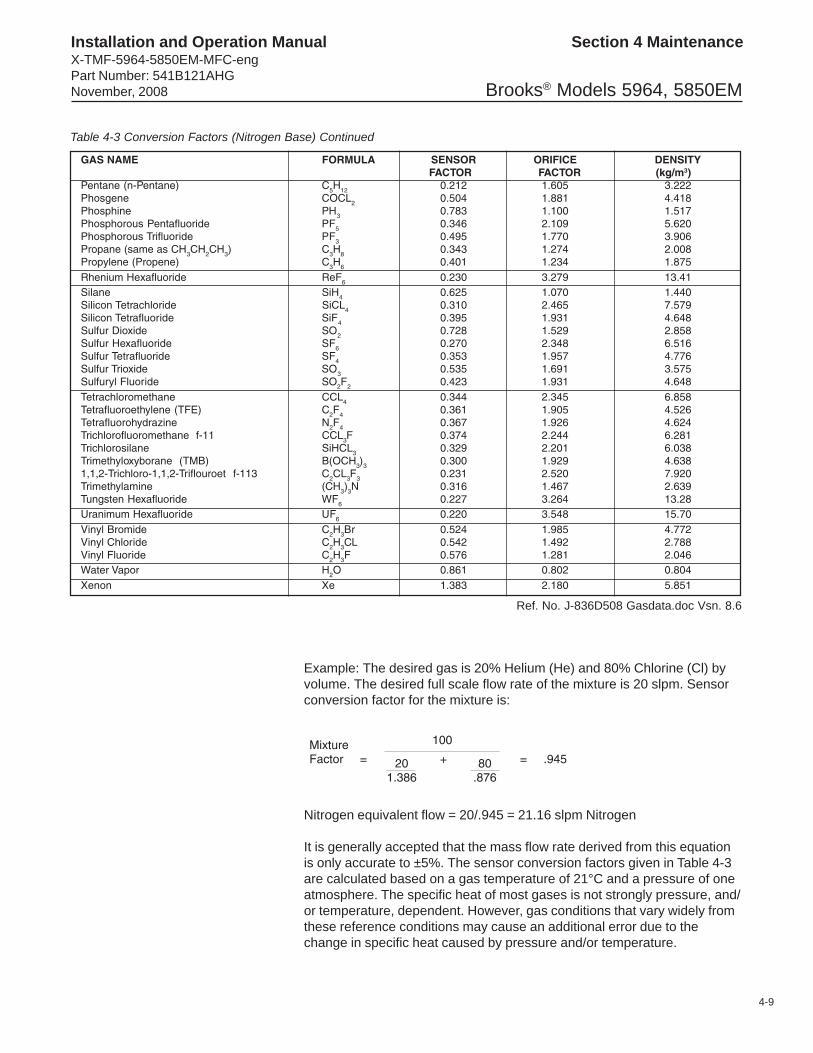
4-9
Brooks® Models 5964, 5850EM
Section 4 MaintenanceInstallation and Operation ManualX-TMF-5964-5850EM-MFC-engPart Number: 541B121AHGNovember, 2008
GAS NAME FORMULA SENSOR ORIFICE DENSITYFACTOR FACTOR (kg/m3)
Pentane (n-Pentane) C5H12 0.212 1.605 3.222Phosgene COCL2 0.504 1.881 4.418Phosphine PH3 0.783 1.100 1.517Phosphorous Pentafluoride PF5 0.346 2.109 5.620Phosphorous Trifluoride PF3 0.495 1.770 3.906Propane (same as CH3CH2CH3) C3H8 0.343 1.274 2.008Propylene (Propene) C3H6 0.401 1.234 1.875Rhenium Hexafluoride ReF6 0.230 3.279 13.41Silane SiH4 0.625 1.070 1.440Silicon Tetrachloride SiCL4 0.310 2.465 7.579Silicon Tetrafluoride SiF4 0.395 1.931 4.648Sulfur Dioxide SO2 0.728 1.529 2.858Sulfur Hexafluoride SF6 0.270 2.348 6.516Sulfur Tetrafluoride SF4 0.353 1.957 4.776Sulfur Trioxide SO3 0.535 1.691 3.575Sulfuryl Fluoride SO2F2 0.423 1.931 4.648Tetrachloromethane CCL4 0.344 2.345 6.858Tetrafluoroethylene (TFE) C2F4 0.361 1.905 4.526Tetrafluorohydrazine N2F4 0.367 1.926 4.624Trichlorofluoromethane f-11 CCL3F 0.374 2.244 6.281Trichlorosilane SiHCL3 0.329 2.201 6.038Trimethyloxyborane (TMB) B(OCH3)3 0.300 1.929 4.6381,1,2-Trichloro-1,1,2-Triflouroet f-113 C2CL3F3 0.231 2.520 7.920Trimethylamine (CH3)3N 0.316 1.467 2.639Tungsten Hexafluoride WF6 0.227 3.264 13.28Uranimum Hexafluoride UF6 0.220 3.548 15.70Vinyl Bromide C2H3Br 0.524 1.985 4.772Vinyl Chloride C2H3CL 0.542 1.492 2.788Vinyl Fluoride C2H3F 0.576 1.281 2.046Water Vapor H2O 0.861 0.802 0.804Xenon Xe 1.383 2.180 5.851
Table 4-3 Conversion Factors (Nitrogen Base) Continued
Ref. No. J-836D508 Gasdata.doc Vsn. 8.6
Example: The desired gas is 20% Helium (He) and 80% Chlorine (Cl) byvolume. The desired full scale flow rate of the mixture is 20 slpm. Sensorconversion factor for the mixture is:
Nitrogen equivalent flow = 20/.945 = 21.16 slpm Nitrogen
It is generally accepted that the mass flow rate derived from this equationis only accurate to ±5%. The sensor conversion factors given in Table 4-3are calculated based on a gas temperature of 21°C and a pressure of oneatmosphere. The specific heat of most gases is not strongly pressure, and/or temperature, dependent. However, gas conditions that vary widely fromthese reference conditions may cause an additional error due to thechange in specific heat caused by pressure and/or temperature.

4-10
Brooks® Models 5964, 5850EM
Section 4 Maintenance Installation and Operation ManualX-TMF-5964-5850EM-MFC-eng
Part Number: 541B121AHGNovember, 2008
4-4 Orifice Sizing
The Orifice Sizing Nomograph, Figure 4-1, is used to calculate the controlvalve's orifice size when changing any or all of the following factors fromthe original factory calibration:
gasoperating pressure (inlet and outlet)flow range
The flow controller's orifice is factory-sized to a preselected gas, operatingpressure and flow range. Note that the orifice is marked with its size inthousandths of an inch. When changing the aforementioned factors,calculate the new orifice size by following the procedure and exampleoutlined in the following paragraphs.
Example: Determine the orifice size for the following conditions:
Gas: HydrogenFlow Rate: 2,000 sccmOutlet Pressure: 30 psigInlet Pressure: 50 psig
1. Determine Nitrogen equivalent flow rate (refer to Table 4-3).
OR
Where:QNITROGEN = Nitrogen equivalent flow rate (sccm)
QGAS = Desired flow rate of the gas (sccm)
ρρρρρNITROGEN = Density of Nitrogen at 70°F
ρρρρρGAS = Density of the gas (taken at customer temperature)
SGGAS = Specific gravity of the gas (taken at customertemperature)
Refer to Table 4-5 for densities.

4-11
Brooks® Models 5964, 5850EM
Section 4 MaintenanceInstallation and Operation ManualX-TMF-5964-5850EM-MFC-engPart Number: 541B121AHGNovember, 2008
Figure 4-1 Model 5850EM Orifice Sizing Nomograph

4-12
Brooks® Models 5964, 5850EM
Section 4 Maintenance Installation and Operation ManualX-TMF-5964-5850EM-MFC-eng
Part Number: 541B121AHGNovember, 2008
Example:
Qgas = 2,000 sccm
= 2,000 x .269
= 538 sccm Nitrogen
In order to calculate the orifice conversion factor when using a gas mixture,the following formula must be used:
Where P1 = percentage by volume of gas 1P2 = percentage by volume of gas 2Pn = percentage by volume of gas n
Example: Find the Nitrogen equivalent for 20 slpm of a 20% Helium and80% Chlorine gas mixture.
QNitrogen = Qgas (orifice conversion factor)
= 20 x 1.439
= 28.78 slpm Nitrogen
2. If inlet and outlet pressures are given in gauge pressure (psig) add 14.7to convert to absolute pressure (psia).
Outlet Pressure — 30 psig + 14.7 = 44.7 psiaInlet Pressure — 50 psig + 14.7 = 64.7 psia

4-13
Brooks® Models 5964, 5850EM
Section 4 MaintenanceInstallation and Operation ManualX-TMF-5964-5850EM-MFC-engPart Number: 541B121AHGNovember, 2008
3. Determine Critical Pressure DropCritical pressure drop occurs when the outlet pressure (psia) is lessthan half the inlet pressure (psia) or
If these conditions exist, the pressure drop (Dp) should be calculatedas follows:
Dp = Pressure drop (psi)Pin = Inlet pressure (psia)
If these conditions do not exist, pressure drop equals the inlet pressureminus the outlet pressure.
Then Dp = 64.7 - 44.7 = 20 psi
4. Using the nomograph, locate the pressure drop (psi) on the vertical linemarked "Dp" (Point A).
5. Locate the Nitrogen equivalent flow rate (sccm Nitrogen) on the verticalline marked "QNitrogen" (Point B).
6. Draw a line connecting Dp and QNitrogen and extend it to the baseline.Mark this point (Point C).
7. Locate inlet pressure (psia) on the vertical line marked "Pin" (Point D).
8. Draw a line connecting Pin (Point D) and baseline (Point C) and thenextend this line to the vertical line marked Do (orifice diameter, inches)(Point E).
9. This point on the line is the minimum orifice size for the givenconditions. If this point is between two orifice sizes, select the nextlargest size orifice to ensure adequate flow. If the orifice selected fallsbelow .0013, choose .0013 size orifice.
For the example in Figure 4-3, the .007 size orifice would be selected.

4-14
Brooks® Models 5964, 5850EM
Section 4 Maintenance Installation and Operation ManualX-TMF-5964-5850EM-MFC-eng
Part Number: 541B121AHGNovember, 2008
Figure 4-2 Example Nomograph

4-15
Brooks® Models 5964, 5850EM
Section 4 MaintenanceInstallation and Operation ManualX-TMF-5964-5850EM-MFC-engPart Number: 541B121AHGNovember, 2008
4-5 Restrictor Sizing
The restrictor assembly is a ranging device for the sensor portion of thecontroller. It creates a pressure drop which is linear with flow rate. Thisdiverts a sample quantity of the process gas flow through the sensor. Eachrestrictor maintains the ratio of sensor flow to restrictor flow, however, thetotal flow through each restrictor is different. Different restrictors (activearea) have different pressure drops and produce controllers with differentfull scale flow rates. For a discussion of the interaction of the various partsof the controller, you are urged to review Section 3-3, Theory of Operation.If the restrictor assembly has been contaminated with foreign matter, thepressure drop versus flow characteristics will be altered and it must becleaned or replaced. It may also be necessary to replace the restrictorassembly when the mass flow controller is to be calibrated to a new flowrate.Restrictor assembly replacement should be performed only by trainedpersonnel. See Section 4-3, Disassembly and Assembly, for restrictorremoval and installation.RestrictorsThe Model 5964/5850EM mass flow controller/device uses two types ofrestrictor assemblies depending on full scale flowrate and expected serviceconditions.
1. Wire mesh for Nitrogen equivalent flow rates above 3.4 slpm. Theserestrictor assemblies are made from a cylinder of wire mesh and areeasily cleaned if they become contaminated in service.
2. Anti-Clog Laminar Flow Element (A.C.L.F.E.) - This type of restrictorassembly is used for Nitrogen equivalent flow rates less than 3.4slpm.
SizingAll Model 5964/5850EM Series Restrictor Assemblies are factory adjustedto provide a specific pressure drop for each flow rate. This corresponds tothe desired full scale flow rate. A list of restrictor assemblies used in theModel 5850EM mass flow controller/device is shown in Table 4-4.
Example:The desired gas is Silane (SiH4).The desired full scale flow rate is 200 sccm.Sensor conversion factor is 0.625 from Table 4-3.Nitrogen equivalent flow = 200/0.625 = 320 sccm Nitrogen

4-16
Brooks® Models 5964, 5850EM
Section 4 Maintenance Installation and Operation ManualX-TMF-5964-5850EM-MFC-eng
Part Number: 541B121AHGNovember, 2008
In the example above a Size P restrictor would be selected.
Note: If the calculated flow rate is such that two different size restrictorscould be used, always select the larger size.
If a mixture of two or more gases is being used, the restrictor selectionmust be based on a Nitrogen equivalent flow rate of the mixture.
Example:The desired gas is 20% Helium (He) and 80% Chlorine (Cl) by volume.The desired full scale flow rate of the mixture is 20 slpm. Sensorconversion factor for the mixture is:
Nitrogen equivalent flow = 20/.945 = 21.16 slpm Nitrogen. In this examplea Size 4 Wire Mesh Assembly would be selected.
Table 4-4 Model 5850EM Standard RestrictorsRange
SCCM Nitrogen Equivalent Flow* Part NumberSize Low High ACLFE Wire Mesh
D 8.038 11.38 S110Z275BMGE 11.25 15.93 S110Z276BMGF 15.75 22.30 S110Z277BMGG 22.05 31.23 S110Z278BMGH 30.88 43.73 S110Z279BMGJ 43.23 61.21 S110Z280BMGK 60.52 85.70 S110Z281BMGL 84.73 119.9 S110Z282BMGM 118.6 167.9 S110Z283BMGN 166.0 235.2 S110Z284BMGP 232.5 329.3 S110Z285BMGQ 325.4 460.9 S110Z286BMGR 455.7 645.3 S110Z287BMGS 638.0 903.4 S110Z288BMGT 893.2 1265. S110Z289BMGU 1250. 1771. S110Z290BMGV 1750. 2479. S110Z291BMGW 2451. 3471. S110Z292BMGX 3431. 4859. S110Z319BMGY 4804. 6802. S110Z321BMG1 6724. 9523. S110Z317BMG2 9388. 13337. S110Z228BMG3 13176. 18667. S110Z226BMG4 18457. 30060. S110Z224BMG
*Materials: BMG = 316 Stainless Steel ElectropolishedCVA = Hastelloy CTM (ACLFE only)DCA = Monel RTM (ACLFE only)
NOTES: • For flow rates less than 8 sccm, use the low flow plug, P/N 618-K-019-BMG in place of a restrictor assembly.• If two sizes are allowed because of overlap, select the larger size.• Restrictor size not required to enter order.

Brooks® Models 5964, 5850EM
A-1
Section A, CE Certification ofMass Flow Equipment
Installation and Operation ManualX-TMF-5964-5850EM-MFC-engPart Number: 541B121AHGNovember, 2008
DanskBrooks Instrument407 West Vine St.Hatfield, PA 19440U.S.A.Emne : Tillæg til instruktions manual.Reference : CE mærkning af Masse Flow udstyrDato : Januar-1996.Brooks Instrument har gennemført CE mærkning af elektronisk udstyr med succes, i henhold til regulativet om elektrisk støj(EMC direktivet 89/336/EEC).Der skal dog gøres opmærksom på benyttelsen af signalkabler i forbindelse med CE mærkede udstyr.Kvaliteten af signal kabler og stik:Brooks lever kabler af høj kvalitet, der imødekommer specifikationerne til CE mærkning.Hvis der anvendes andre kabel typer skal der benyttes et skærmet kabel med hel skærm med 100% dækning.Forbindelses stikket type “D” eller “cirkulære”, skal være skærmet med metalhus og eventuelle PG-forskruninger skal entenvære af metal eller metal skærmet.Skærmen skal forbindes, i begge ender, til stikkets metalhus eller PG-forskruningen og have forbindelse over 360 grader.Skærmen bør være forbundet til jord.“Card Edge” stik er standard ikke af metal, der skal derfor ligeledes benyttes et skærmet kabel med hel skærm med 100%dækning.Skærmen bør være forbundet til jord.Forbindelse af stikket; venligst referer til vedlagte instruktions manual.Med venlig hilsen,
DeutschBrooks Instrument407 West Vine St.Hatfield, PA 19440U.S.A.Subject : Nachtrag zur Bedienungsanleitung.Referenz : CE Zertifizierung für MassedurchflußgeräteDatum : Januar-1996.Nach erfolgreichen Tests enstprechend den Vorschiften der Elektromagnetischen Verträglichkeit (EMC Richtlinie 89/336/EEC) erhalten die Brooks-Geräte (elektrische/elektronische Komponenten) das CE-Zeichen.Bei der Auswahl der Verbindungskabel für CE-zertifizierte Geräte sind spezielle Anforderungen zu beachten.Qualität der Verbindungskabel, Anschlußstecker und der KabeldurchführungenDie hochwertigen Qualitätskabel von Brooks entsprechen der Spezifikation der CE-Zertifizierung.Bei Verwendung eigener Verbindungskabel sollten Sie darauf achten, daß eine100 %igenSchirmababdeckung des Kabels gewährleistet ist.•“D” oder “Rund” -Verbindungsstecker sollten eine Abschirmung aus Metall besitzen.Wenn möglich, sollten Kabeldurchführungen mit Anschlußmöglichkeiten für die Kabelabschrimung verwendet werden.Die Abschirmung des Kabels ist auf beiden Seiten des Steckers oder der Kabeldurchführungen über den vollen Umfang von360 ° anzuschließen.Die Abschirmung ist mit dem Erdpotential zu verbinden.Platinen-Steckverbindunger sind standardmäßige keine metallgeschirmten Verbindungen. Um die Anforderungen der CE-Zertifizierung zu erfüllen, sind Kabel mit einer 100 %igen Schirmababdeckung zu verwenden.Die Abschirmung ist mit dem Erdpotential zu verbinden.Die Belegung der Anschlußpins können Sie dem beigelegten Bedienungshandbuch entnehmen.

A-2
Brooks® Models 5964, 5850EM
Section CE Certification Installation and Operation ManualX-TMF-5964-5850EM-MFC-eng
Part Number: 541B121AHGNovember, 2008
EnglishBrooks Instrument407 West Vine St.Hatfield, PA 19440U.S.A.Subject : Addendum to the Instruction Manual.Reference : CE certification of Mass Flow EquipmentDate : January-1996.The Brooks (electric/electronic) equipment bearing the CE mark has been successfully tested to the regulations of the ElectroMagnetic Compatibility (EMC directive 89/336/EEC).Special attention however is required when selecting the signal cable to be used with CE marked equipment.Quality of the signal cable, cable glands and connectors:Brooks supplies high quality cable(s) which meets the specifications for CE certification.If you provide your own signal cable you should use a cable which is overall completely screened with a 100% shield.“D” or “Circular” type connectors used should be shielded with a metal shield. If applicable, metal cable glands must be usedproviding cable screen clamping. The cable screen should be connected to the metal shell or gland and shielded at both ends over 360 Degrees.The shield should be terminated to a earth ground.Card Edge Connectors are standard non-metallic. The cables used must be screened with 100% shield to comply with CEcertification.The shield should be terminated to a earth ground.For pin configuration : Please refer to the enclosed Instruction Manual.
EspañolBrooks Instrument407 West Vine St.Hatfield, PA 19440U.S.A.Asunto : Addendum al Manual de Instrucciones.Referencia : Certificación CE de los Equipos de Caudal MásicoFecha : Enero-1996.Los equipos de Brooks (eléctricos/electrónicos) en relación con la marca CE han pasado satisfactoriamente las pruebasreferentes a las regulaciones de Compatibilidad Electro magnética (EMC directiva 89/336/EEC).Sin embargo se requiere una atención especial en el momento de seleccionar el cable de señal cuando se va a utilizar unequipo con marca CECalidad del cable de señal, prensaestopas y conectores:Brooks suministra cable(s) de alta calidad, que cumple las especificaciones de la certificación CE .Si usted adquiere su propio cable de señal, debería usar un cable que esté completamente protegido en su conjunto con unapantallamiento del 100%.Cuando utilice conectores del tipo “D” ó “Circular” deberían estar protegidos con una pantalla metálica. Cuando sea posible,se deberán utilizar prensaestopas metálicos provistos de abrazadera para la pantalla del cable.La pantalla del cable deberá ser conectada al casquillo metálico ó prensa y protegida en ambos extremos completamenteen los 360 Grados.La pantalla deberá conectarse a tierra.Los conectores estandar de tipo tarjeta (Card Edge) no son metálicos, los cables utilizados deberán ser protegidos con unapantallamiento del 100% para cumplir con la certificación CE.La pantalla deberá conectarse a tierra.Para ver la configuración de los pines: Por favor, consultar Manual de Instrucciones adjunto.

Brooks® Models 5964, 5850EM
A-3
Section A, CE Certification ofMass Flow Equipment
Installation and Operation ManualX-TMF-5964-5850EM-MFC-engPart Number: 541B121AHGNovember, 2008
FrançaisBrooks Instrument407 West Vine St.Hatfield, PA 19440U.S.A.Sujet : Annexe au Manuel d’Instructions.Référence : Certification CE des Débitmètres Massiques à Effet Thermique.Date : Janvier 1996.Messieurs,Les équipements Brooks (électriques/électroniques) portant le label CE ont été testés avec succès selon les règles de laCompatibilité Electromagnétique (directive CEM 89/336/EEC).Cependant, la plus grande attention doit être apportée en ce qui concerne la sélection du câble utilisé pour véhiculer le signald’un appareil portant le label CE.Qualité du câble, des presse-étoupes et des connecteurs:Brooks fournit des câbles de haute qualité répondant aux spécifications de la certification CE.Si vous approvisionnez vous-même ce câble, vous devez utiliser un câble blindé à 100 %.Les connecteurs « D » ou de type « circulaire » doivent être reliés à la terre.Si des presse-étoupes sont nécessaires, ceux ci doivent être métalliques avec mise à la terre.Le blindage doit être raccordé aux connecteurs métalliques ou aux presse-étoupes sur le pourtour complet du câble, et àchacune de ses extrémités.Tous les blindages doivent être reliés à la terre.Les connecteurs de type « card edge » sont non métalliques. Les câbles utilisés doivent être blindés à 100% pour satisfaire àla réglementation CE.Tous les blindages doivent être reliés à la terre.Se référer au manuel d’instruction pour le raccordement des contacts.
Greek

A-4
Brooks® Models 5964, 5850EM
Section CE Certification Installation and Operation ManualX-TMF-5964-5850EM-MFC-eng
Part Number: 541B121AHGNovember, 2008
NederlandsBrooks Instrument407 West Vine St.Hatfield, PA 19440U.S.A.Onderwerp : Addendum voor Instructie HandboekReferentie: CE certificering voor Mass Flow Meters & ControllersDatum : Januari 1996Dames en heren,Alle CE gemarkeerde elektrische en elektronische produkten van Brooks Instrument zijn met succes getest en voldoen aande wetgeving voor Electro Magnetische Compatibiliteit (EMC wetgeving volgens 89/336/EEC).Speciale aandacht is echter vereist wanneer de signaalkabel gekozen wordt voor gebruik met CE gemarkeerde produkten.Kwaliteit van de signaalkabel en kabelaansluitingen:• Brooks levert standaard kabels met een hoge kwaliteit, welke voldoen aan de specificaties voor CE certificering.
Indien men voorziet in een eigen signaalkabel, moet er gebruik gemaakt worden van een kabel die volledig isafgeschermd met een bedekkingsgraad van 100%.
• “D” of “ronde” kabelconnectoren moeten afgeschermd zijn met een metalen connector kap. Indien kabelwartels wordentoegepast, moeten metalen kabelwartels worden gebruikt die het mogelijk maken het kabelscherm in te klemmenHet kabelscherm moet aan beide zijden over 360° met de metalen connectorkap, of wartel verbonden worden.Het scherm moet worden verbonden met aarde.
• “Card-edge” connectors zijn standaard niet-metallisch. De gebruikte kabels moeten volledig afgeschermd zijn met eenbedekkingsgraad van 100% om te voldoen aan de CE certificering.
Het scherm moet worden verbonden met aarde.Voor pin-configuraties a.u.b. verwijzen wij naar het bijgesloten instruktie handboek.Hoogachtend,
ItalianoBrooks Instrument407 West Vine St.Hatfield, PA 19440U.S.A.Oggetto : Addendum al manuale di istruzioni.Riferimento : Certificazione CE dei misuratori termici di portata in massaData : Gennaio 1996.Questa strumentazione (elettrica ed elettronica) prodotta da Brooks Instrument, soggetta a marcatura CE, ha superato consuccesso le prove richieste dalla direttiva per la Compatibilità Elettomagnetica (Direttiva EMC 89/336/EEC).E’ richiesta comunque una speciale attenzione nella scelta dei cavi di segnale da usarsi con la strumentazione soggetta amarchio CE.Qualità dei cavi di segnale e dei relativi connettori:Brooks fornisce cavi di elevata qualità che soddisfano le specifiche richieste dalla certificazione CE. Se l’utente intendeusare propri cavi, questi devono possedere una schermatura del 100%.I connettori sia di tipo “D” che circolari devono possedere un guscio metallico. Se esiste un passacavo esso deve esseremetallico e fornito di fissaggio per lo schermo del cavo.Lo schermo del cavo deve essere collegato al guscio metallico in modo da schermarlo a 360° e questo vale per entrambe leestemità.Lo schermo deve essere collegato ad un terminale di terra.I connettori “Card Edge” sono normalmente non metallici. Il cavo impiegato deve comunque avere una schermatura del 100%per soddisfare la certificazione CE.Lo schermo deve essere collegato ad un terminale di terra.Per il corretto cablaggio dei terminali occorre fare riferimento agli schemi del manuale di istruzioni dello strumento.

Brooks® Models 5964, 5850EM
A-5
Section A, CE Certification ofMass Flow Equipment
Installation and Operation ManualX-TMF-5964-5850EM-MFC-engPart Number: 541B121AHGNovember, 2008
NorskBrooks Instrument407 West Vine St.Hatfield, PA 19440U.S.A.Vedrørende : Vedlegg til håndbokReferanse : CE sertifisering av utstyr for massestrømsmåling og reguleringDato : Januar 1996
Til den det angårBrooks Instrument elektrisk og elektronisk utstyr påført CE-merket har gjennomgått og bestått prøver som beskrevet i EMCforskrift om elektromagnetisk immunitet, direktiv 89/336/EEC.For å opprettholde denne klassifisering er det av stor viktighet at riktig kabel velges for tilkobling av det måletekniske utstyret.
Utførelse av signalkabel og tilhørende plugger:• Brooks Instrument tilbyr levert med utstyret egnet kabel som møter de krav som stilles til CE-sertifisering.• Dersom kunden selv velger kabel, må kabel med fullstendig, 100% skjerming av lederene benyttes.“D” type og runde plugger og forbindelser må være utført med kappe i metall og kabelnipler må være utført i metall for jordetinnfesting av skjermen. Skjermen i kabelen må tilknyttes metallet i pluggen eller nippelen i begge ender over 360°, tilkobletelektrisk jord.• Kort-kantkontakter er normalt utført i kunststoff. De tilhørende flatkabler må være utført med fullstendig, 100% skjermingsom kobles til elektrisk jord på riktig pinne i pluggen, for å møte CE sertifiseringskrav.For tilkobling av medleverte plugger, vennligst se håndboken som hører til utstyret.Vennlig hilsen
Português
Brooks Instrument407 West Vine St.Hatfield, PA 19440U.S.A.Assunto : Adenda ao Manual de InstruçõesReferência : Certificação CE do Equipamento de Fluxo de MassaData : Janeiro de 1996.O equipamento (eléctrico/electrónico) Brooks com a marca CE foi testado com êxito nos termos do regulamento daCompatibilidade Electromagnética (directiva CEM 89/336/EEC).Todavia, ao seleccionar-se o cabo de sinal a utilizar com equipamento contendo a marca CE, será necessário ter umaatenção especial.Qualidade do cabo de sinal, buchas de cabo e conectores:A Brooks fornece cabo(s) de qualidade superior que cumprem os requesitos da certificação CE.Se fornecerem o vosso próprio cabo de sinal, devem utilizar um cabo que, na sua totalidade, seja isolado com uma blindagem de 100%.Os conectores tipo “D” ou “Circulares” devem ser blindados com uma blindagem metálica. Se tal for necessário, deve utilizar-se buchas metálicas de cabo para o isolamento do aperto do cabo.O isolamento do cabo deve ser ligado à blindagem ou bucha metálica em ambas as extremidades em 360º.A blindagem deve terminar com a ligação à massa.Os conectores “Card Edge” não são, em geral, metálicos e os cabos utilizados devem ter um isolamento com blindagem a100% nos termos da Certificação CE..A blindagem deve terminar com ligação à massa.Relativamente à configuração da cavilha, queiram consultar o Manual de Instruções.

A-6
Brooks® Models 5964, 5850EM
Section CE Certification Installation and Operation ManualX-TMF-5964-5850EM-MFC-eng
Part Number: 541B121AHGNovember, 2008
SuomiBrooks Instrument407 West Vine St.Hatfield, PA 19440U.S.A.Asia : Lisäys KäyttöohjeisiinViite : Massamäärämittareiden CE sertifiointiPäivämäärä : Tammikuu 1996Brooksin CE merkillä varustetut sähköiset laitteet ovat läpäissyt EMC testit (direktiivi 89/336/EEC).Erityistä huomiota on kuitenkin kiinnitettävä signaalikaapelin valintaan.Signaalikaapelin, kaapelin läpiviennin ja liittimen laatuBrooks toimittaa korkealaatuisia kaapeleita, jotka täyttävät CE sertifikaatin vaatimukset. Hankkiessaan signaalikaapelin itse,olisi hankittava 100%:sti suojattu kaapeli.“D” tai “Circular” tyyppisen liitimen tulisi olla varustettu metallisuojalla. Mikälì mahdollista, tulisi käyttää metallisiakaapeliliittimiä kiinnitettäessä suojaa.Kaapelin suoja tulisi olla liitetty metallisuojaan tai liittimeen molemmissa päissä 360°:n matkalta.Suojan tulisi olla maadoitettu.“Card Edge Connector”it ovat standarditoimituksina ei-metallisia. Kaapeleiden täytyy olla 100%: sesti suojattuja jotta neolisivat CE sertifikaatin mukaisia.Suoja on oltava maadoitettu.Nastojen liittäminen; katso liitteenä oleva manuaali.Ystävällisin terveisin,
SvenskBrooks Instrument407 West Vine St.Hatfield, PA 19440U.S.A.Subject : Addendum to the Instruction ManualReference : CE certification of Mass Flow EquipmentDate : January 1996Brooks (elektriska / elektronik) utrustning, som är CE-märkt, har testats och godkänts enligt gällande regler förelektromagnetisk kompabilitet (EMC direktiv 89/336/EEC).Speciell hänsyn måste emellertid tas vid val av signalkabel som ska användas tillsammans med CE-märkt utrustning.Kvalitet på signalkabel och anslutningskontakter:Brooks levererar som standard, kablar av hög kvalitet som motsvarar de krav som ställs för CE-godkännande.Om man använder en annan signalkabel ska kabeln i sin helhet vara skärmad till 100%.“D” eller “runda” typer av anslutningskontakter ska vara skärmade. Kabelgenomföringar ska vara av metall alternativt medmetalliserad skärmning.Kabelns skärm ska, i bada ändar, vara ansluten till kontakternas metallkåpor eller genomföringar med 360 gradersskärmning.Skärmen ska avslutas med en jordförbindelse.Kortkontakter är som standard ej metalliserade, kablar som används måste vara 100% skarmade för att överensstämma medCE-certifieringen.Skärmen ska avslutas med en jordförbindelse.För elektrisk anslutning till kontaktstiften hänvisas till medföljande instruktionsmanual.

Brooks® Models 5964, 5850EM
Installation and Operation ManualX-TMF-5964-5850EM-MFC-engPart Number: 541B121AHGNovember, 2008
THIS PAGE WASINTENTIONALLY
LEFT BLANK

Installation and Operation ManualX-TMF-5964-5850EM-MFC-eng
Part Number: 541B121AHGNovember, 2008Brooks® Models 5964, 5850EM
TRADEMARKSBrooks ................................................................. Brooks Instrument, LLCFreon ........................................................ E.I. DuPont de Nemours & Co.Kalrez .................................................................. DuPont Dow ElastomersTeflon ........................................................ E.I. DuPont de Nemours & Co.VCO ............................................................................................ Cajon Co.VCR ............................................................................................ Cajon Co.Viton ...................................................... DuPont Performance ElastomersVol-U-Meter ......................................................... Brooks Instrument, LLC
LIMITED WARRANTYSeller warrants that the Goods manufactured by Seller will be free from defects in materials or workmanship under normal useand service and that the Software will execute the programming instructions provided by Seller until the expiration of theearlier of twelve (12) months from the date of initial installation or eighteen (18) months from the date of shipment by Seller.Products purchased by Seller from a third party for resale to Buyer (“Resale Products”) shall carry only the warranty extendedby the original manufacturer.All replacements or repairs necessitated by inadequate preventive maintenance, or by normal wear and usage, or by fault ofBuyer, or by unsuitable power sources or by attack or deterioration under unsuitable environmental conditions, or by abuse,accident, alteration, misuse, improper installation, modification, repair, storage or handling, or any other cause not the fault ofSeller are not covered by this limited warranty, and shall be at Buyer’s expense.Goods repaired and parts replaced during the warranty period shall be in warranty for the remainder of the original warrantyperiod or ninety (90) days, whichever is longer. This limited warranty is the only warranty made by Seller and can beamended only in a writing signed by an authorized representative of Seller.
BROOKS SERVICE AND SUPPORTBrooks is committed to assuring all of our customers receive the ideal flow solution for their application, along withoutstanding service and support to back it up. We operate first class repair facilities located around the world to providerapid response and support. Each location utilizes primary standard calibration equipment to ensure accuracy and reliabilityfor repairs and recalibration. The primary standard calibration equipment to calibrate our flow products is certified by ourlocal Weights and Measures Authorities and traceable to the relevant International Standards.Visit www.BrooksInstrument.com to locate the service location nearest to you.
START-UP SERVICE AND IN-SITU CALIBRATIONBrooks Instrument can provide start-up service prior to operation when required.For some process applications, where ISO-9001 Quality Certification is important, it is mandatory to verify and/or (re)calibratethe products periodically. In many cases this service can be provided under in-situ conditions, and the results will be traceableto the relevant international quality standards.
CUSTOMER SEMINARS AND TRAININGBrooks Instrument can provide customer seminars and dedicated training to engineers, end users and maintenance persons.Please contact your nearest sales representative for more details.
HELP DESKIn case you need technical assistance:
Americas 1-888-554-FLOWEurope +(31) 318 549 290 Within Netherlands 0318 549 290Asia +011-81-3-5633-7100
Due to Brooks Instrument's commitment to continuous improvement of our products, all specifications are subject to changewithout notice.