Embed Size (px)
Citation preview

Broadband high-reflection multilayercoatings at oblique angles of incidence
Konstantin V. Popov, J. A. Dobrowolski, Alexander V. Tikhonravov,and Brian T. Sullivan
The angular properties of various wideband high reflectors are investigated. The theory is developed forthe design of high reflectors based on contiguous quarter-wave stacks for use at one oblique angle or fora range of angles of incidence. Numerical results are presented for several high reflectors designed tohave a high reflectance in the 0.4–0.8-mm spectral region for use at 50° and with angles of incidenceranging between 0° and 50°. A random error perturbation analysis shows that such layer systems canbe produced experimentally. © 1997 Optical Society of America
1. Introduction
There are many scientific and technological applica-tions for broadband high reflectance coatings ~see,e.g., the article by Ferencz and Szipocs1!. There isalso an increasing demand for broadband high-reflectance coatings that operate at nonnormal lightincidence. Broadband high-reflectance coatings de-scribed in the past can be classified into two basiccategories. In the first, the maximum possible re-flectance is sought and the transmitted light is of noconsequence. In the second category, both thetransmitted and reflected light are important. Suchpartial reflectors, with a transmittance between 0.05and 0.10, find applications, for example, in Fabry–Perot and other types of interferometers. Here weare only concerned with broadband reflectors of thefirst category, in which a reflectance higher than 0.97is usually desired.In the past, several types of broadband high reflec-
tors have been described that are based on singleopaque metal layers or on all-dielectric and metal-dielectric multilayer systems. It is useful to have abetter understanding of the angular properties ofthese different types of high-reflectance coatings.This can assist in the development of multilayer
K. V. Popov and A. V. Tikhonravov are with the Research Com-puter Center, Moscow State University, Moscow 119899, Russia.J. A. Dobrowolski and B. T. Sullivan are with the Institute forMicrostructural Sciences, National Research Council of Canada,Ottawa, Ontario K1A 0R6, Canada.Received 7 May 1996; revised manuscript received 26 July 1996.0003-6935y97y102139-13$10.00y0© 1997 Optical Society of America
starting designs with a minimum number of layersand a minimum overall thickness for subsequent re-finement. However, it appears that there has been nosystematic investigation in the open literature of theangular properties of such coatings. To our knowl-edge, the only reflecting coatings whose angularproperties have been investigated at length are single-period quarter-wave stack reflectors, which have alimited wavelength region of high reflectance.2–4Here we discuss some of the basic angular and
bandwidth properties of high reflectors and use thisknowledge for the design of broadband high reflectorsand for an understanding of their basic limitations.In particular, we concentrate on broadband high re-flectors of the multiperiod quarter-wave stack type.In Section 2 we present a review of the bandwidth
and angular properties of different types of high-reflectance coatings and discuss their relative advan-tages and disadvantages. In Section 3 the theory ofbroadband reflectors based on contiguous quarter-wave stacks is reviewed. Next, in Section 4, meth-ods are considered for the design of broadbandreflectors of this type for one specific oblique angle ofincidence as well as for a range of angles. In Section5 the calculated performance is presented for multi-layer coatings that have been designed for a highreflectance for both p and s polarizations in the visi-ble spectral region, 0.4–0.8 mm. In Section 6 thestability of these designs with respect to thicknesserrors is investigated. Finally, some concluding re-marks are made in the Section 7.
2. Performance Review of Existing Systems
The first broadband high-reflectance coatings werebased on reflection from metal surfaces. In the case
1 April 1997 y Vol. 36, No. 10 y APPLIED OPTICS 2139

of metals, the highest reflectance in the visible spec-tral region is obtained from a silver surface. Thereflectance of Ag, calculated from the optical con-stants given by Lynch and Hunter,5 is shown in Fig.1. In this and other similar diagrams in this paper,the graph in row A shows the refractive index profileof the system plotted against the optical thickness,along with the number of layers and the overall op-tical thickness of the layer system. Rows B throughG show the reflectance of the system for p- ands-polarized light at angles of incidence from 0° to 50°,in intervals of 10°. The average normal incidencereflectance of an opaque Ag layer in the 0.4–0.8 mmspectral region is '0.95. For oblique angles of inci-dence there is a polarization splitting, but the aver-
Fig. 1. Calculated performance at various angles of incidence of aAg–air interface. Row A depicts the interface between opaque Agand the incident medium. Rows B–G represent the reflectance ofAg for p- and s-polarized light incident at angles of 0° to 50°.
2140 APPLIED OPTICS y Vol. 36, No. 10 y 1 April 1997
age reflectance of the s- and p-polarized light staysapproximately constant. However, there is nowavelength shift of the spectral features that is socharacteristic of all-dielectric multilayer systems.The disadvantage of opaque Ag layers is that theirreflectance may be somewhat lower than desired.Furthermore, the reflectance of an Ag layer will de-grade over time unless layers are added to protect itfrom corrosion.6,7Aluminum is more stable and has a much wider
region of high reflectance than Ag. Usually the thinAl2O3 layer that forms on its surface protects the Alfrom further atmospheric corrosion. However, addi-tional protective layers have to be added for high UVreflectance. Unfortunately, the average reflectanceof Al is '0.91, which is lower than that of Ag in thevisible spectral region. It is possible to enhance thereflectance of Al by overcoating it with a suitabledielectric multilayer system.8 In Fig. 2 are shownthe calculated results for an 11-layer dielectric layersystem on opaque Al. The optical constants of Alused in the calculations were those given by Smith etal.9 In these and subsequent calculations, the twodielectric materials used were assumed to be nonab-sorbing and to have nondispersive refractive indicesof 1.45 and 2.35, roughly corresponding to SiO2 andNb2O5, respectively. The overall optical thickness ofthe dielectric layer system is 1.46 mm. The averagereflectance of the reflector at normal incidence is'0.97. This time, with an increase in the angle ofincidence, the polarization splitting is accompaniedby a distinct shift of the spectral features toward theshorter wavelengths. By increasing the overallthickness and the number of the dielectric layers, onecan bring the enhanced metal reflectance arbitrarilyclose to unity. However, after a certain point, theenhanced metal coatings have no intrinsic advantageover the purely all-dielectric coatings described be-low.The first all-dielectric reflecting coatings were
based on stacks consisting of pairs of quarter-wavelayers of alternating high and low refractive indexmaterials.10 The theory of such quarter-wave stackscan be found in all basic texts on optical thinfilms.11–14 However, with the coating materials thatare available, it may not be possible to provide a highreflectance over the desired broad spectral regionwith only a single-period quarter-wave stack.It appears that Penselin and Steudel were the first
to attempt to enhance the width of the high-reflectance region.15 Although they were concernedwith the design of partial reflectors, the method thatthey described works equally well for high reflectors.In an alternating high and low refractive index stack,adjacent layers i and i 1 1 were monitored to bequarter-wave layers at wavelengths li and li11, re-spectively, such that ~1yli 2 1yli11! 5 const. Thebroader region of high reflectance is achieved, ofcourse, at the expense of a larger number of layersand a larger overall optical thickness of the resultinglayer system.
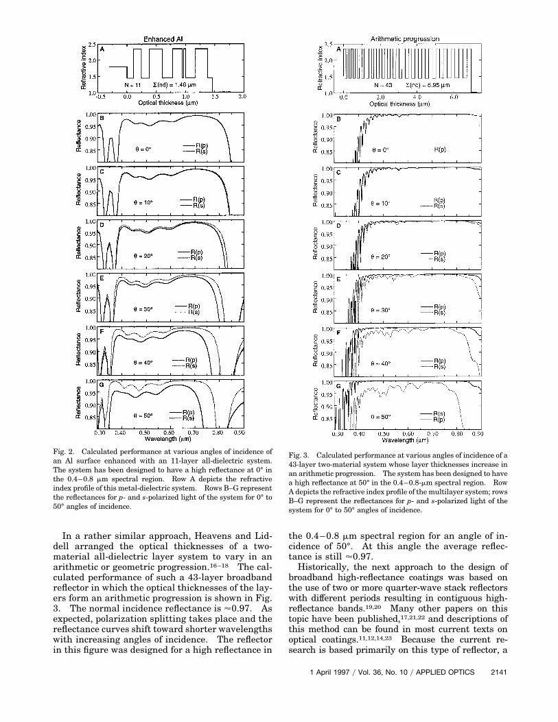
In a rather similar approach, Heavens and Lid-dell arranged the optical thicknesses of a two-material all-dielectric layer system to vary in anarithmetic or geometric progression.16–18 The cal-culated performance of such a 43-layer broadbandreflector in which the optical thicknesses of the lay-ers form an arithmetic progression is shown in Fig.3. The normal incidence reflectance is '0.97. Asexpected, polarization splitting takes place and thereflectance curves shift toward shorter wavelengthswith increasing angles of incidence. The reflectorin this figure was designed for a high reflectance in
Fig. 2. Calculated performance at various angles of incidence ofan Al surface enhanced with an 11-layer all-dielectric system.The system has been designed to have a high reflectance at 0° inthe 0.4–0.8 mm spectral region. Row A depicts the refractiveindex profile of this metal-dielectric system. Rows B–G representthe reflectances for p- and s-polarized light of the system for 0° to50° angles of incidence.
the 0.4–0.8 mm spectral region for an angle of in-cidence of 50°. At this angle the average reflec-tance is still '0.97.Historically, the next approach to the design of
broadband high-reflectance coatings was based onthe use of two or more quarter-wave stack reflectorswith different periods resulting in contiguous high-reflectance bands.19,20 Many other papers on thistopic have been published,17,21,22 and descriptions ofthis method can be found in most current texts onoptical coatings.11,12,14,23 Because the current re-search is based primarily on this type of reflector, a
Fig. 3. Calculated performance at various angles of incidence of a43-layer two-material system whose layer thicknesses increase inan arithmetic progression. The system has been designed to havea high reflectance at 50° in the 0.4–0.8-mm spectral region. RowA depicts the refractive index profile of themultilayer system; rowsB–G represent the reflectances for p- and s-polarized light of thesystem for 0° to 50° angles of incidence.
1 April 1997 y Vol. 36, No. 10 y APPLIED OPTICS 2141

more detailed review of the theory will be given inSection 3.For the sake of completeness, it is worth mention-
ing that it is also possible to obtain a high reflectanceover an extended spectral region with two-materialsystems that consist of several hundred layers of ran-dom thicknesses.24–26 The performance of a repre-sentative 199-layer system of this type is shown inFig. 4. Although the average reflectance is quitehigh, there are many narrow-reflection minimathroughout the spectral region of interest. This mayor may not be a problem, depending on the desiredapplication. The advantage of such randomizedlayer systems is that the average reflectance is quite
Fig. 4. Calculated performance at various angles of incidence of a199-layer two-material system with random layer thicknesses.The system has been designed to have a high reflectance at 50° inthe 0.4–0.8 mm spectral region. Row A depicts the refractiveindex profile of the multilayer system.
2142 APPLIED OPTICS y Vol. 36, No. 10 y 1 April 1997
insensitive to thickness errors. A disadvantage isthat the layer system is many times thicker thannecessary to achieve the same reflectance by theother methods described above. With the use of con-ventional depositionmethods this may have a seriousimpact on their cost. However, this may not be alimitation for long. Plastic multilayer coatings con-sisting of hundreds of layers are currently producedby coextrusion and are stable and cheap enough tofind extensive use for decorative purposes to exploittheir attractive iridescent behavior.27 Furthermore,optical multilayers consisting of hundreds of layershave also been produced in the past by chemicalvapor-deposition methods.28 It is reasonable to as-sume that further progress in these processes will bemade and that stable and cheap reflectors of this typewill become available.
3. Theory of Wideband High Reflectors Based onContiguous Reflectance Bands
A. Contiguous and Overlapping High-Reflectance Bands
As mentioned above, a high reflectance over an ex-tended spectral range can be obtained by depositingtwo or more all-dielectric quarter-wave stacks withindividual high-reflectance bands that are either con-tiguous or overlapping.Consider a multilayer coating consisting of two
subsystems 1 and 2 ~not necessarily periodic!, eachcomposed of nonabsorbing optically homogeneouslayers, with a spacer layer placed between them.Assume the substrate is nonabsorbing and has a re-fractive index ns and that the ambient medium has arefractive index na. The transmittance T of such acoating is given by the expression14
T5T1T2
11 ~12T1!~12T2! 2 2 cos2cÎ~1 2 T1!~1 2 T2! ,
(1)
where T1 and T2 are the transmittance of the firstand second subsystems, respectively. The parame-ter c is defined by the phase changes on reflectionfrom subsystems 1 and 2 and the phase thickness ofthe spacer layer. Equation ~1! is valid for both nor-mal and oblique incidences of light and for s- orp-polarized light.It follows from Eq. ~1! that if the high-reflectance
bands ~the spectral regions where the transmittanceis close to zero! of the subsystems do not overlap, thetransmittance T can be made arbitrarily small inboth bands by simply decreasing T1 and T2. Indeed,if T1 tends to zero and at the same time T2 differsconsiderably from zero, then, according to Eq. ~1!, Talso tends to zero.The situation is more complicated when the high-
reflectance bands of the subsystems overlap ~i.e., T1and T2 are both small!. It follows from Eq. ~1! thatsmall values of both T1 and T2 do not necessarilycause a small value of T. A classical example of thisis a narrow-bandpass transmission filter consisting of

a half-wave spacer placed between two identicalquarter-wave mirrors.In general, if the high-reflectance bands of the sub-
systems overlap, i.e., T1 and T2 are both close to zero,then T will not necessarily be close to zero at thewavelengths of the overlap region where the condi-tion
cos 2c < 1 (2)
is satisfied.Consider the situation with overlapping high-
reflectance bands in more detail. When relation~2! does not hold in a region of overlap, then fromEq. ~1! it is always possible to obtain in this regiona value of T arbitrarily close to zero by simply de-creasing T1 and T2. It follows from Eq. ~1! that ifrelation ~2! holds at some wavelength in an overlapregion, it is still possible to obtain a value of Tarbitrarily close to zero by fixing T1 at a value closeto zero and by decreasing T2. Because we are deal-ing with the case in which subsystems 1 and 2 areperiodic stacks, then it is always possible to obtaina small value of T in the regions of overlap throughthe proper choice of the number of periods in eachstack.We concentrate on broadband high reflectors at
oblique light incidence based on two or more all-dielectric quarter-wave stacks that have individualhigh-reflectance bands that are either contiguous oroverlapping. Hence we need to consider the angularproperties of a single quarter-wave stack.
B. Principal High-Reflectance Band of a Quarter-WaveStack at an Oblique Incidence of Light
Let us first examine the location of the boundariesof the principal high-reflectance band of a quarter-wave stack designed for oblique light incidence.Consider a stack that consists of pairs of layers withrefractive indices nL and nH and physical thick-nesses dL and dH. If at an angle of incidence uq thecondition
dLÎnL2 2 aq 5 dHÎnH
2 2 aq 5l0
4(3)
is satisfied, where aq 5 na2 sin2 uq, then the principal
high-reflectance bands for s- and p-polarized light arecentered at wavelength l0. The angle uq at whichcondition ~3! is fulfilled is called the quarter-waveangle. Let other angles of incidence be denoted by uand their corresponding angular parameters na
2 sin2 ube denoted by a.The wavelength boundaries of a high-reflectance
band at an angle u are determined by the condition14
Fs, p~l, a! 5 21, (4)
where
Fs, p~l, a! 5 cosS2p
ldHÎnH
2 2 aDcosS2p
ldLÎnL
2 2 aD212
Fs, p~a!sinS2p
ldHÎnH
2 2 aD3 sinS2p
ldLÎnL
2 2 aD . (5)
Here the indices s and p refer to s- and p-polarizedlight, respectively, and the function Fs, p~a! is definedas
Fs, p~a! 5hLs, p~a!
hHs, p~a!
1hH
s, p~a!
hLs, p~a!
, (6)
where
hL,Hs ~a! 5 ÎnL, H
2 2 a, hL,Hp ~a! 5
nL,H2
ÎnL, H2 2 a
(7)
are the effective refractive indices of the low and highrefractive index materials at an angle u.The upper ~lu! and lower ~ll! boundaries of the
principal high-reflectance band of the quarter-wavestack at angle uq are obtained by solving Eq. ~4! witha 5 aq. The expressions for these boundaries are14
lus, p 5 l0
p
p 2 Bs, p,
lls, p 5 l0
p
p 1 Bs, p, (8)
where Bs, p 5 arccos~2js, p! and
js, p 5@hL
s, p~aq!#2 1 @hH
s, p~aq!#2 2 6hL
s, p~aq!hHs, p~aq!
@hLs, p~aq! 1 hH
s, p~aq!#2 . (9)
Note that Bs, p is approximately proportional to thebandwidth of the high-reflectance zone centered at agiven wavelength l0. Hence the bandwidth of thehigh-reflectance zone depends only on the ratio of thehigh and low effective refractive indices and increasesmonotonically with this ratio. Because ~hH
p yhLp! ,
~hHs yhL
s ! for all angles, the high reflectance band forp-polarized light is therefore always narrower thanthat for s-polarized light.Let us consider how the positions of the boundaries
of the principal high-reflectance band change whenthe angle of incidence deviates from a given quarter-wave angle uq. We derive the expressions for thederivatives of these boundaries with respect to theangular parameter a.Equation ~4! defines the boundary positions as an
implicit function of the angle of incidence ~or the an-gular parameter a!. Hence, by taking the partialderivatives of Eq. ~4! with respect to l and a, one cansolve for ~dlu,l
s,pyda! at a 5 aq, i.e.,
dlu, ls, p
da5 2
~]Fs, py]a!
~]Fs, py]l!at l 5 lu, l
s, p, a 5 aq. (10)
1 April 1997 y Vol. 36, No. 10 y APPLIED OPTICS 2143

It can then be shown from Eqs. ~5! and ~10! that for spolarization,
1lu, ls
dlu, ls
da5 2
14 F 1
~hLs !2
11
~hHs !2G
6lu, l
sÎhLshH
s
pl0~hLshH
s !2~hH
s 2 hLs !, (11)
and for p polarization,
1lu, lp
dlu, lp
da5 2
14 F 1
~hLs !2
11
~hHs !2G
6 sign~hHp 2 hL
p!lu, lp ÎhL
phHp
pl0~hLshH
s !2~hL
s !2 2 ~hHs !2
hHp 1 hL
p .
(12)
Note that the effective refractive indices in Eqs. ~11!and ~12! are calculated at the quarter-wave angle uq.In Eqs. ~11! and ~12! the plus over minus sign beforethe second term on the right-hand side of the equalsign is minus for the lower boundary and plus for theupper boundary. The function sign~hH
p 2 hLp! is de-
fined as
sign~hHp 2 hL
p! 5 H 1 if hHp . hL
p
21 if hHp , hL
p . (13)
The case in which hHp is equal to hL
p is trivial and willnot be considered further because the reflectance ofp-polarized light is then equal to that of the baresubstrate.In Appendix A it is shown that ~dlu,l
s, pyda! , 0 for allangles of incidence uq and for all values of na, nL, andnH. That is, as the angle of incidence is decreasedfrom the value uq the high-reflectance band bound-aries for both polarizations always shift towardlonger wavelengths, and similarly they shift towardshorter wavelengths if the angle of incidence is in-creased.
4. Design of Reflectors for Oblique Light Incidence
A. Nonpolarizing Wideband High Reflectors for a SingleAngle of Incidence
The goal of this subsection is to design a coating thathas a high reflectance for both s- and p-polarized lightin the wavelength region ~lL, lU! for a given angle ofincidence uq.As wasmentioned above, the high-reflectance band
of an individual quarter-wave stack for p-polarizedlight is narrower than that for s-polarized light.Therefore, one way to design the desired reflector is tocombine the smallest number of quarter-wave stacksrequired to cover the entire ~lL, lU! spectral regionwith their high-reflectance bands for p-polarizedlight. The high-reflectance bands of the stacks fors-polarized light will then cover the entire ~lL, lU!region automatically.From Eq. ~8!, for p-polarized light the ratio of the
2144 APPLIED OPTICS y Vol. 36, No. 10 y 1 April 1997
boundary wavelengths for the jth stack is given by
lu, jp
ll, jp 5
p 1 Bp
p 2 Bp, (14)
so that for exactly contiguous bands, i.e., lu, j11p 5 ll, j
p ,it is easy to show that if lu,1
p 5 lU then the number ofstacks required is given by
N $ln~lUylL!
ln@~p 1 Bp!y~p 2 Bp!#. (15)
Also, from Eqs. ~3! and ~8!, the required effective op-tical thicknesses Dj of the layers of the jth stack aregiven by
Dj 5lU
4p
~p 2 Bp!j
~p 1 Bp!j21 . (16)
If a band overlap for p-polarized light is desired, i.e.,lu, j11p 5 ll, j
p ~1 1 b!, where b is an overlap parameter,formulas ~15! and ~16! can be adjusted accordingly.In any case, the overlapping of high-reflectance bandsof the stacks may occur for p-polarized light and willcertainly occur for s-polarized light, and this mayresult in undesirable reflectance minima in the ~lL,lU! region. These minima can be eliminated eitherby ~a! refinement of the layer thicknesses, or by ~b!proper choice of the total number of layers in eachstack.For a numerical example, we can use the above
theory to design a high reflector at an angle uq 5 50°to cover the spectral region from lL 5 0.4 mm to lU 50.8 mm. For ns 5 1.52, na 5 1.00, nH 5 2.35, and nL5 1.45, we have hH
p 5 2.49, hLp 5 1.71, hH
s 5 2.22, andhLs 5 1.23, giving Bp 5 0.3731 and Bs 5 0.5821.
Hence, from formulas ~3!, ~15! and ~16!, three quarter-wave stacks are required, centered at wavelengths l0,15 0.705 mm, l0,2 5 0.555 mm, and l0,3 5 0.437 mm.The number of periods in each stack is the same and isequal to 7. The refractive index profile and the per-formance of the high-reflectance filter are shown in theleft column of Fig. 5. Note that the layer thicknessesin this system have not been refined.
B. Nonpolarizing Broadband, Wide-Angle High Reflectors
Here we propose a way to design a coating that has ahigh-reflectance for both s- and p-polarized light inthe wavelength region ~lL, lU! over a broad angularrange ~uL, uU!. As above, we concentrate on highreflectors based on two or more all-dielectric quarter-wave stacks that have individual high-reflectancebands that are either contiguous or overlapping.Consider the filter designed to have high reflec-
tance in the wavelength region ~lL, lU! for an angle uqby the technique described in Subsection 4.A withoutrefinement. From Section 3 it is possible to deter-mine under what conditions, for p-polarized light,contiguous high-reflectance bands of two neighboringquarter-wave stacks of the filter will start to overlap asthe angle of incidence is changed. If ll,1
p is the lower-wavelength boundary of the higher-wavelength reflec-

Fig. 5. Calculated performanceat various angles of incidence ofbroadband reflectors consistingof several contiguous quarter-wave stacks. Column 1 repre-sents the performance of a 43-layer system consisting of threequarter-wave stacks designed tohave a high reflectance in the0.4–0.8 mmspectral region for anangle of incidence of 50°.Column 2 depicts the perfor-mance of a four quarter-wavestack 57-layer system designedto have a high reflectance in thesame spectral region for all an-gles between 0° and 50°.
tance stack ~1! and lu,2p is the upper-wavelength
boundary of the lower-wavelength reflectance stack~2!, then if these two bands are exactly contiguous, i.e.,lu,2p 5 ll,1
p , it follows from Eq. ~12! that at an angle uq,
d~lu, 2p 2 ll, 1
p !
da5 sign~hH
p 2 hLp!~lu,2
p !2ÎhL
phHp
p~hLshH
s !2
3~hL
s !2 2 ~hHs !2
hHp 1 hL
p S 1l0, 2
11
l0, 1D . (17)
Let us analyze Eq. ~17!. It follows from Eq. ~7!that @~hL
s !2 2 ~hHs !2# is always negative. Thus the
factor ~hHp 2 hL
p! defines the sign of the derivative onthe left-hand side of Eq. ~17!.
There may exist an angle ub, where hHp 5 hL
p. Ac-cording to Eq. ~7! this equality is satisfied if
ub 5 arcsinnHnL
naÎnH2 1 nL
2. (18)
Clearly, such an angle exists if the condition
nHnLnaÎnH
2 1 nL2
, 1 (19)
is fulfilled.Effective refractive indices for p-polarized light al-
ways increase monotonically with the angle of inci-dence u. At normal light incidence, hH
p . hLp.
1 April 1997 y Vol. 36, No. 10 y APPLIED OPTICS 2145

Hence, hHp . hL
p for u , ub and hHp , hL
p for u . ub.Therefore, it follows from Eq. ~17! that
d~lu, 2p 2 ll, 1
p !
da, 0 if uq , ub,
d~lu, 2p 2 ll, 1
p !
da. 0 if uq . ub (20)
in the vicinity of quarter-wave angle uq.Let us now consider a filter composed of two quarter-
wave stacks with high-reflectance bands that are con-tiguous for p-polarized light. Because ~dlu,l
p yda! , 0for all angles, it follows from condition ~20! that, forp-polarized light and for uq , ub, the contiguous high-reflectance bands will start to overlap and shift towardlonger wavelengths when the angle of incidence is de-creased from uq. For the case in which uq . ub, thehigh-reflectance bands will start to overlap and shifttoward shorter wavelengths if the angle of incidence isincreased from uq. For s-polarized light, the two high-reflectance bands will already overlap and will con-tinue to do so for any change of the angle of incidencefrom its initial value uq. Hence, assuming that theinitial design has a sufficiently broadband region ofhigh reflectance, we see that a reflector designed for asingle angle uq will be effective at all smaller angles ifuq , ub, and it will work at all higher angles if uq . ub.Thus, to obtain nonpolarizing reflectors for the
wavelength range ~lL, lU! and the angular range ~uL,uU!, one must use the techniques described in Sub-section 4.A to design reflectors with a high reflectanceover a broader wavelength region. To ensure thatthe reflectance is high at the minimum desired angleuL for the case in which uU , ub, one must make surethat the high-reflectance bands cover the wavelengthregion ~l#L, lU! at the angle uq 5 uU, where l#L , lL.For a high reflectance at the maximum desired angleuU for the case in which uL . ub, the high-reflectancebands must cover the wavelength region ~lL, l#U! atthe angle uq 5 uL, where l#U . lU. Combining thesequarter-wave stacks into a single filter and eliminat-ing undesirable reflectance minima at all the anglesof interest, either by ~a! refinement of the layersthicknesses or by ~b! proper choice of the total num-ber of layers in each stack, one can then obtain therequired high reflector.
5. Numerical Examples and Discussion
The methods described in Section 4 were used todesign high-reflectance filters for the 0.4–0.8 mmspectral region, both for an angle of incidence of 50°and for angles of incidence ranging from 0° to 50°.In the first column of Fig. 5 are shown the refrac-
tive index profile and the spectral performance atdifferent angles of incidence of a 43-layer high re-flector, consisting of three contiguous quarter-wavestacks, designed for use with light incident at 50°.The total optical thickness of the system is 6.83 mm.The layers in this system have not been refined, and
2146 APPLIED OPTICS y Vol. 36, No. 10 y 1 April 1997
thus the optical thicknesses of all the high and lowrefractive index layers in each stack are the same.The average reflectance of the reflector for lightincident at 50° is 0.98. As expected, there is a shiftof the high-reflectance band toward longer wave-lengths as the angle of incidence is decreased. Thewavelength shift is such that the reflectance is nolonger high at the lower wavelength boundary of 0.4mm for light incident at a normal angle.Column 2 of Fig. 5 depicts the performance of a
high reflector designed for use at all angles of inci-dence up to and including 50°. It is essentially thesystem of column 1, but with one additional contigu-ous quarter-wave stack added to extend the high-reflectance region at normal incidence below thelower-wavelength boundary of 0.4 mm. The result-ing system consists of 57 layers and has an opticalthickness of 8.18 mm. The average reflectance ofthis high reflector for an angle of incidence of 50° is0.98.The easiest method to remove the numerous shal-
low minima that are observed at the higher angles ofincidence in the p-reflectance curves of Fig. 5 is theuse of more layers in the various contiguous quarter-wave stacks that make up the high reflector. In Fig.6 are shown high reflectors designedwithmore layersto minimize the shallow minima. The high reflec-tors designed solely for an angle of incidence of 50°and for the 0° to 50° angle of incidence range areshown in columns 1 and 2 of Fig. 6, respectively, andconsist of 55 and 97 layers. The total overall opticalthicknesses of the two systems are 8.73 and 13.88mm, respectively. The average reflectance for thetwo reflectors, at an angle of incidence of 50°, are0.995 and 0.997, respectively.The shallow minima in the reflectance curves of
Fig. 5 can also be removed through refinement of thethicknesses of the layers of the systems depicted inrow A. The results obtained when all the layerthicknesses of the two high reflectors were numeri-cally refined are shown in Fig. 7. As one can see inthis figure, the fluctuations in the reflectance curvesare now much reduced. One can also see that thenumber of layers in the two systems is unchangedand that the overall optical thicknesses of the twosystems, 6.99 and 8.93 mm, are not very differentfrom those of the original systems. The average re-flectances for the two reflectors at an angle of inci-dence of 50°, 0.992 and 0.993, are also quite similar tothose of the original systems.
6. Influence of Thickness Errors on the Properties ofthe High Reflectors
The solutions described in Section 5 have a satis-factory performance. The question is: Are theypractical? Can they be produced experimentallywith commercially available deposition systems?This question is best answered by performing nu-merical simulations of the monitoring process.Preliminary simulations showed that quartz crystal

Fig. 6. Analogous to Fig. 5, exceptthat the number of layers in thetwo multilayer systems has beenincreased to 55 and 97, respec-tively. It is seen that the ripplesin the s-polarized reflectancecurves are thereby considerably re-duced.
monitoring techniques ~or time monitoring, whenused with steady deposition processes such as mag-netron sputtering! should yield better results thanoptical monitoring methods without real-time eval-uation and reoptimization of the systems.29,30 Ac-cordingly, in Fig. 8 are shown the results of quartzcrystal monitoring simulations for the followinghigh reflectors: row A, 43-layer arithmetic pro-gression system ~Fig. 3!; row B, 43-layer systemconsisting of three contiguous quarter-wave stacks~Fig. 5!; row C, 43-layer refined version of the above~Fig. 7!; and row D, 55-layer system consisting ofthree contiguous quarter-wave stacks ~Fig. 6!.The simulations were performed 30 times by using3% random error perturbations of the layer thick-nesses. In the calculations the optical constants ofall materials were assumed to be constant, which isvalid when high-energy deposition processes areused.
In Fig. 8, columns 1 and 2 correspond to p- ands-polarized light, respectively. The heavy curvesrepresent the reflectances for the unperturbed sys-tems for light incident at 50°. The shaded areasindicate where the reflectances of 67% of the exper-imentally produced reflectors should lie within.It can be seen that for all the high reflectors inves-
tigated, the 3% random thickness errors have essen-tially no effect on the reflectance curves fors-polarized light. There is a larger variation in thereflectance for p-polarized light, but the performanceis still quite acceptable. It should therefore be pos-sible to construct coatings of this type.It should be noted here that all of the coatings
depicted in Fig. 8 were designed only to have a highreflectance for an angle of incidence of 50°. A ran-dom error analysis performed on high reflectors thatwere designed for angles of incidence ranging fromzero to 50° yielded analogous results.
1 April 1997 y Vol. 36, No. 10 y APPLIED OPTICS 2147

Fig. 7. Calculated performance atvarious angles of incidence of thetwo multilayer systems that re-sulted from the refinement of alllayer thicknesses of the systemsdepicted in Fig. 5, row A.
7. Conclusions
In this paper the angular properties of various highwideband reflectors were investigated. The theorywas developed for the design of high reflectors basedon contiguous quarter-wave stacks for use at eitherone oblique angle or for a range of angles. The re-sults show that, in the absence of absorption andscattering, it is possible to achieve any desired reflec-tance, providing that enough layers are used in thedesign.Numerical results were presented for several high
reflectors, based on contiguous quarter-wave stacks,designed to have a high reflectance in the 0.4–0.8 mmspectral region for use at either 50° or for use atangles of incidence ranging from 0° to 50°. A ran-dom thickness error perturbation analysis has shownthat, as far as layer thickness monitoring is con-cerned, it should be possible to produce such layer
2148 APPLIED OPTICS y Vol. 36, No. 10 y 1 April 1997
systems experimentally. Clearly, the samemethodscan be used to design high reflectors for other spectralregions and angle of incidence ranges. These meth-ods can also be applied to high reflectors for use witheither s- or p-polarized light only.In Fig. 8, rows A, B, and C present data for high
reflectors based on a system in which the opticalthicknesses of the layers are in an arithmetic pro-gression, and on systems based on three contiguousstacks before and after refinement of the layer thick-nesses, respectively. All three systems consist of 43layers, and all have approximately the same overalloptical thickness. It is clear from the diagram thatthe system based on the refined version of the threecontiguous stacks has the best performance.High reflectors of the type depicted in Fig. 7 appear
to be well suited for the calibration of spectrophoto-meters and reflectometers and should also find many

Fig. 8. Effect of 3% random errorperturbations of the layer thick-nesses on the calculated reflec-tance at an angle of incidence of50° for p- and s-polarized light ~col-umns 1 and 2, respectively!.Rows A, B, C, and D correspond tothe layer systems of Figs. 3, 5, 7,and 6, respectively. The heavycurves represent the reflectance ofthe unperturbed systems. The re-flectance curves of 67% of experi-mentally produced systems shouldfall within the shaded areasshown.
other applications. However, a word of caution is inorder. The calculations assumed that the opticalconstants were nondispersive and that there was noabsorption or scattering. Certainly, the dispersionof the refractive indices results in second-order effectson the performance of the high reflectors that can bereadily allowed for by refinement of the layer thick-nesses. However, the effect of finite extinction coef-ficients of the coating materials is more serious. Ithas long been known that even small extinction co-
Fig. 9. Effect of finite extinction coefficients of the coating mate-rials on the calculated absorptance for the system depicted incolumn 2 of Fig. 7 for s- and p-polarized light incident at an angleof 50°. The extinction coefficients of the materials used for thesecalculations were kH 5 kL 5 0.005. Also shown is the derivativeof the phase change on reflection with respect to wavelength.
efficients can introduce significant amounts of ab-sorption in themultilayer.31 This can be seen in Fig.9, where the absorptance is calculated for the systemshown in column 2 of Fig. 7, for an angle of incidenceof 50°, assuming the low- and high-index materialshave extinction coefficients of 0.005. A similar dete-rioration in performance when some of the materialsare absorbing is also observed for all the other all-dielectric and metal-dielectric layer systems pre-sented in this paper. Thus, for the bestexperimental implementation of broadband high-reflectance coatings, a deposition process is requiredthat produces coatings with low absorption. Alsoshown in Fig. 9, as a matter of interest, is the deriv-ative of the phase change on reflection with respect tothe wavelength. The remarkable similarity be-tween the absorptance and the reflection phasechange derivative curves in the high-reflectance bandwas first pointed out in Ref. 1. This apparent cor-respondence between the absorptance and the reflec-tion phase change derivative still does not have atheoretical explanation.
Appendix A
It is now shown that dlu,lp,syda , 0 for all uq and for all
values of na, nL, and nH. The two cases, for s- andp-polarized light, are examined separately.
A. s-Polarized Light
Equation ~11! yields expressions for the derivativesdlu,l
syda. Let us examine these expressions.
1. lu,ls 5 ll
s. The fact that dllsyda is always less
than zero follows directly from Eq. ~11! because bothterms on the right-hand side of the equation are lessthan zero.
1 April 1997 y Vol. 36, No. 10 y APPLIED OPTICS 2149

2. lu,ls 5 lu
s . In order to prove that dlusyda , 0, it
is sufficient to show that the absolute value of thesecond term in Eq. ~11! is always less than the abso-lute value of the first. It is thus necessary to showthat
ÎhLshH
s
~hLshH
s !2~hH
s 2 hLs !
114
$@1y~hLs !2# 1 @1y~hH
s !2#%
,pl0
lus .
(A1)
The above inequality can be rewritten in the moreconvenient form
F 4ÎhLshH
s
~hLs 1 hH
s !GF~hHs !2 2 ~hL
s !2
~hHs !2 1 ~hL
s !2G ,pl0
lus . (A2)
The second factor on the left-side of inequality ~A2!is clearly less than unity. Hence it is sufficient toshow that
4ÎhLshH
s
~hLs 1 hH
s !,
pl0
lus . (A3)
Let b represent the ratio hLs yhH
s . Using Eqs. ~8!and ~9!, we can rewrite inequality ~A3! in the follow-ing way:
f ~b! , g~b!, (A4)
where
f ~b! 54Îb1 1 b
g~b! 5 p 2 arccos6b 2 b2 2 1
~1 1 b!2. (A5)
The value of b can vary from zero to one. Figure 10demonstrates that inequality ~A4! is satisfied in thisinterval.It has thus been established that dlu,l
s yda , 0 forall angles uq and for all values of na, nL, and nH.
B. p-Polarized Light
Equation ~12! yields the expressions for the deriva-tives dlu,l
p yda. We show that the absolute value of
Fig. 10. Variation of functions f ~b!, g~b! @Eq. ~A5!# with b 5 hLs, py
hHs, p ~see Appendix A!.
2150 APPLIED OPTICS y Vol. 36, No. 10 y 1 April 1997
the second term in Eq. ~12! is always less than theabsolute value of the first term.
1. lu,lp 5 ll
p. It suffices to show that
F ÎhLphH
p
0.5~hLp 1 hH
p !GF~hHp !2 2 ~hL
p!2
~hHp !2 1 ~hL
p!2G ,pl0
2llp . (A6)
The first factor on the left-hand side of inequality ~A6!is always less than unity—it is a well-known fact thatthe average geometric value of a number of quantitiescannot be larger than their arithmetic average.Thus, the entire left-hand side of inequality ~A6! isalways less than unity. In contrast,
pl0
2llp .
p
2. 1. (A7)
This means that dllpyda is always less than zero.
2. lu,lp 5 lu
p. It is sufficient to show that
4ÎhLphH
p
~hLp 1 hH
p !,
pl0
lup . (A8)
If the ratio hLpyhH
p is denoted by b in the above in-equality, then one obtains inequality ~A4!. Thevalue of b can vary now from zero to infinity. Thevalidity of inequality ~A4! has already been estab-lished for 0 , b , 1. It is thus necessary to showthat inequality ~A4! remains satisfied for 1 , b , `.Now, it follows from Eq. ~A5! that f ~b! 5 f ~1yb! andg~b! 5 g~1yb!. Hence, if inequality ~A4! is valid forintervals from zero to one, then it is also valid for theinterval from one to infinity.We have thus shown that dlu,l
p,syda , 0 for all an-gles uq and for all values of na, nL, and nH.
The authors acknowledge the assistance of theircolleague, M. Trubetskov. This research was sup-ported by North Atlantic Treaty Organization link-age grant HTECH.LG 930841-1284~93!.
References1. K. Ferencz and R. Szipocs, “Recent developments of laser op-
tical coatings in Hungary,” Appl. Opt. 32, 2525–2538 ~1993!.2. P. Baumeister, “The transmission and degree of polarization of
quarter-wave stacks at non-normal incidence,” Opt. Acta 8,105–119 ~1961!.
3. H. F. Mahlein, “Properties of laser mirrors at non-normal in-cidence,” Opt. Acta 20, 687–697 ~1973!.
4. A. V. Tikhonravov, “Multilayer dielectric mirrors with obliquelight incidence,” Opt. Spectrosc. ~USSR! 54, 216–219 ~1983!.
5. D. W. Lynch and W. R. Hunter, “Comments on the opticalconstants of metals and an introduction to the data for severalmetals,” in Handbook of Optical Constants of Solids, E. D.Palik, ed. ~Academic, Orlando, Fla., 1985!, pp. 275–367.
6. G. Hass, J. B. Heaney, J. F. Osantowski, and J. J. Triolo,“Reflectance and durability of Ag mirrors coated with thinlayers of Al2O3 plus reactively deposited silicon oxide,” Appl.Opt. 14, 2639–2644 ~1975!.
7. E. A. Volgunova, G. I. Golubeva, and A. M. Klochkov, “Highlystable silver mirrors,” Sov. J. Opt. Technol. 50, 128–129~1983!.

8. G. Hass, “Filmed surfaces for reflecting objects,” J. Opt. Soc.Am. 45, 945–952 ~1955!.
9. D. Y. Smith, E. Shiles, and M. Inokuti, “The optical propertiesof metallic aluminum,” in Handbook of Optical Constants ofSolids, E. D. Palik, ed. ~Academic, Orlando, Fla., 1985!, pp.369–406.
10. W. Geffcken and E. Berger, “Lichtfilter aus einer Mehrzahllichtdurchlassiger, nichtmetallischer Schichten, von denen im-mer je zwei voneinander durch eine ebensolche Schicht, jedochvon anderer Brechungszahl, getrennt sind,” German patent904357 ~11 April 1943!.
11. Z. Knittl, Optics of Thin Films ~Wiley, London, 1976!, p. 548.12. H. A. Macleod, Thin Film Optical Filters ~McGraw-Hill, New
York, 1986!.13. A. Thelen, Design of Optical Interference Coatings ~McGraw-
Hill, Company, New York, 1988!.14. S. A. Furman and A. V. Tikhonravov, Optics of Multilayer
Systems ~Editions Frontieres, Gif-sur-Yvette, France, 1992!.15. S. Penselin and A. Steudel, “Fabry–Perot-Interferometer-
verspiegelungen aus dielektrischen Vielfachschichten,” Z.Phys. 142, 21–41 ~1955!.
16. O. S. Heavens and H. M. Liddell, “Staggered broad-band re-flecting multilayers,” Appl. Opt. 5, 373–376 ~1966!.
17. F. A. Korolev, A. Y. Klementeva, T. F. Meshcheryakova, andI. A. Ramazina, “Wide-band reflectors with multilayer dielec-tric coatings,” Opt. Spectrosc. ~USSR! 28, 416–419 ~1970!.
18. M. A. Khashan, “A Fresnel formula for dielectric multilayermirrors,” Optik 54, 363–371 ~1979!.
19. D. L. Perry, “Broadband dielectricmirrors formultiple wavelengthlaser operation in the visible,” Proc. IEEE 53, 76–77 ~1965!.
20. A. F. Turner and P. W. Baumeister, “Multilayer mirrors withhigh reflectance over an extended spectral region,” Appl. Opt.5, 69–76 ~1966!.
21. Z. Knittl, “Applications of thin films in optics and the princi-ples and methods of their design,” in Thin Film Technologies I,J. R. Jacobsson, ed., Proc. SPIE 401, 2–18 ~1983!.
22. W. H. Southwell, “Extended bandwidth reflector designs usingwavelets,” in Optical Interference Coatings, Vol. 17 of 1995OSA Technical Digest Series ~Optical Society of America,Washington, D.C., 1995!, pp. 11–13.
23. A. Thelen, “Design of optical minus filters,” J. Opt. Soc. Am. 61,365–369 ~1971!.
24. K. M. Yoo and R. R. Alfano, “Broad bandwidth mirror withrandom layer thicknesses,” Appl. Opt. 28, 2456–2458 ~1989!.
25. K. M. Yoo and R. R. Alfano, “Photon localization in a disor-dered multilayered system,” Phys. Rev. B 39, 5806–5809~1989!.
26. V. A. Antonov and V. I. Pshenitsyn, “Transmission of an elec-tromagnetic wave through randomly organized layered struc-tures,” Opt. Spectrosc. ~USSR! 69, 394–396 ~1990!.
27. T. J. Alfrey, E. F. Gurnee, and W. J. Schrenk, “Physical opticsof iridescent multilayered plastic films,” Polym. Eng. Sci. 9,400–404 ~1969!.
28. L. Edmonds, P. Baumeister, M. Krisl, and N. Boling, “Spectralcharacteristics of a narrowband rejection filter,” Appl. Opt. 29,3203–3204 ~1990!.
29. B. T. Sullivan and J. A. Dobrowolski, “Deposition error com-pensation for optical multilayer coatings: I. Theoretical de-scription,” Appl. Opt. 31, 3821–3835 ~1992!.
30. B. T. Sullivan and J. A. Dobrowolski, “Deposition error com-pensation for optical multilayer coatings. II. Experimentalresults—sputtering system,” Appl. Opt. 32, 2351–2360 ~1993!.
31. A. V. Tikhonravov, “On the synthesis of multilayer opticalsystems,” Ph.D. dissertation ~Moscow State University, Mos-cow, 1973!.
1 April 1997 y Vol. 36, No. 10 y APPLIED OPTICS 2151

![Oblique-incidence radio transmission and the Lorentz ...nvlpubs.nist.gov/nistpubs/jres/26/jresv26n2p105_A1b.pdf · Smith] Radio Transmission and Lorentz Term 107 The method of calculating](https://img.dokumen.tips/doc/110x75/5ab715837f8b9ab7638e6f29/oblique-incidence-radio-transmission-and-the-lorentz-radio-transmission-and.jpg)


