Embed Size (px)
Citation preview

BREVIAR DE CALCUL
SEPARATOR ORIZONTAL TRIFAZIC 80mc
P3902-BC
REVIZIE
1 30.10.2012
A.Maftei A.Stoica G.Colea Rev. Data Descriere Intocmit Verificat Aprobat

Table of Contents Warnings and Errors : ............................................................................................................................... 4
Input Echo : .................................................................................................................................................... 5
XY Coordinate Calculations : ............................................................................................................. 22
Internal Pressure Calculations : .................................................................................................... 23
Element and Detail Weights : ............................................................................................................. 31
Nozzle Flange MAWP : ................................................................................................................................ 34
Wind Load Calculation : ......................................................................................................................... 36
Earthquake Load Calculation : ........................................................................................................... 39
Center of Gravity Calculation : ...................................................................................................... 41
Horizontal Vessel Analysis (Ope.) : ............................................................................................. 42
Horizontal Vessel Analysis (Test) : ............................................................................................. 62
Nozzle Calcs. : GV1a ................................................................................................................................ 78
Nozzle Calcs. : R1 .................................................................................................................................... 82
Nozzle Calcs. : R3 .................................................................................................................................... 86
Nozzle Calcs. : GV2a ................................................................................................................................ 90
Nozzle Calcs. : GV2b ................................................................................................................................ 94
Nozzle Calcs. : M1 .................................................................................................................................... 98
Nozzle Calcs. : R8 .................................................................................................................................. 102
Nozzle Calcs. : R2 .................................................................................................................................. 106
Nozzle Calcs. : R6 .................................................................................................................................. 110
Nozzle Calcs. : R7c ................................................................................................................................ 114
Nozzle Calcs. : R7b ................................................................................................................................ 118
Nozzle Calcs. : R7a ................................................................................................................................ 122
Nozzle Calcs. : R5 .................................................................................................................................. 126
Nozzle Calcs. : R4 .................................................................................................................................. 130
Nozzle Calcs. : R17b .............................................................................................................................. 134
Nozzle Calcs. : R17d .............................................................................................................................. 138
Nozzle Calcs. : R11 ................................................................................................................................ 143
Nozzle Calcs. : R9 .................................................................................................................................. 147
Nozzle Calcs. : R18a .............................................................................................................................. 152
Nozzle Calcs. : R10 ................................................................................................................................ 157
Nozzle Calcs. : R12 ................................................................................................................................ 162
Nozzle Calcs. : R17a .............................................................................................................................. 167
Nozzle Calcs. : R20 ................................................................................................................................ 171

Nozzle Calcs. : GV1b .............................................................................................................................. 175
Nozzle Calcs. : R19 ................................................................................................................................ 179
Nozzle Calcs. : R15 ................................................................................................................................ 183
Nozzle Calcs. : R18b .............................................................................................................................. 187
Nozzle Calcs. : R16 ................................................................................................................................ 191
Nozzle Calcs. : R14 ................................................................................................................................ 195
Nozzle Calcs. : R13 ................................................................................................................................ 199
Nozzle Schedule :..................................................................................................................................... 203
Nozzle Summary : ....................................................................................................................................... 207
Vessel Design Summary : ....................................................................................................................... 222
DESIGN CALCULATION
In Accordance with European Code EN-13445
Analysis Performed by : CONFIND S.R.L.
Job File : D:\PROIECTE CONFIND\P3902-SOT 80 MC\LUCRU\PVELIT
Date of Analysis : Nov 7,2012
PV Elite 2011, March 2011, Service Pack 1

PV Elite 2011 SP1 Licensee: CONFIND S.R.L. FileName : P3902-BC -------------------------------------- Warnings and Errors : Step: 0 7:08a Nov 7,2012
4
Class From To : Basic Element Checks.
==========================================================================
Class From To: Check of Additional Element Data
==========================================================================
There were no geometry errors or warnings.
PV Elite is a trademark of Intergraph CADWorx & Analysis Solutions, Inc. 2011

PV Elite 2011 SP1 Licensee: CONFIND S.R.L. FileName : P3902-BC -------------------------------------- Input Echo : Step: 1 7:08a Nov 7,2012
5
PV Elite Vessel Analysis Program: Input Data
Design Internal Pressure (for Hydrotest) 0.6000 MPa
Design Internal Temperature 60 C
Type of Hydrotest 1
Hydrotest Position Horizontal
Projection of Nozzle from Vessel Top 0.0000 mm
Projection of Nozzle from Vessel Bottom 0.0000 mm
Minimum Design Metal Temperature -20 C
Type of Construction Welded
Special Service None
Degree of Radiography N/A
Miscellaneous Weight Percent 0.
Use Higher Longitudinal Stresses (Flag) Y
Select t for Internal Pressure (Flag) N
Select t for External Pressure (Flag) N
Select t for Axial Stress (Flag) N
Select Location for Stiff. Rings (Flag) N
Consider Vortex Shedding N
Perform a Corroded Hydrotest N
Is this a Heat Exchanger No
User Defined Hydro. Press. (Used if > 0) 0.0000 MPa
User defined MAWP 0.0000 MPa
User defined MAPnc 0.0000 MPa
Load Case 1 NP+EW+WI+FW+BW
Load Case 2 NP+EW+EE+FS+BS
Load Case 3 NP+OW+WI+FW+BW
Load Case 4 NP+OW+EQ+FS+BS
Load Case 5 NP+HW+HI
Load Case 6 NP+HW+HE
Load Case 7 IP+OW+WI+FW+BW
Load Case 8 IP+OW+EQ+FS+BS

PV Elite 2011 SP1 Licensee: CONFIND S.R.L. FileName : P3902-BC -------------------------------------- Input Echo : Step: 1 7:08a Nov 7,2012
6
Load Case 9 EP+OW+WI+FW+BW
Load Case 10 EP+OW+EQ+FS+BS
Load Case 11 HP+HW+HI
Load Case 12 HP+HW+HE
Load Case 13 IP+WE+EW
Load Case 14 IP+WF+CW
Load Case 15 IP+VO+OW
Load Case 16 IP+VE+OW
Load Case 17 IP+VF+CW
Load Case 18 FS+BS+IP+OW
Load Case 19 FS+BS+EP+OW
Wind Design Code ASCE-7 93
Design Wind Speed 112.65 km/hr
Exposure Constant C
Importance Factor 1.
Roughness Factor 1
Base Elevation 0.0000 mm
Percent Wind for Hydrotest 33.
Using User defined Wind Press. Vs Elev. N
Damping Factor (Beta) for Wind (Ope) 0.0100
Damping Factor (Beta) for Wind (Empty) 0.0000
Damping Factor (Beta) for Wind (Filled) 0.0000
Seismic Design Code UBC 1997
UBC Seismic Zone (1=1,2=2a,3=2b,4=3,5=4) 0
UBC Importance Factor 1.250
UBC Seismic Coefficient Ca 0.360
UBC Seismic Coefficient Cv 0.840
UBC Seismic Coefficient Nv 1.000
UBC Horizontal Force Factor 2.000
Apply Allowables per paragraph 1612.3.2 No

PV Elite 2011 SP1 Licensee: CONFIND S.R.L. FileName : P3902-BC -------------------------------------- Input Echo : Step: 1 7:08a Nov 7,2012
7
Design Nozzle for Des. Press. + St. Head Y
Consider MAP New and Cold in Noz. Design N
Consider External Loads for Nozzle Des. Y
Use ASME VIII-1 Appendix 1-9 N
Complete Listing of Vessel Elements and Details:
Element From Node 10
Element To Node 20
Element Type Elliptical
Description FUND ELIPSOIDAL 1
Distance "FROM" to "TO" 50.000 mm
Inside Diameter 3000.0 mm
Element Thickness 14.000 mm
Internal Corrosion Allowance 3.0000 mm
Nominal Thickness 14.000 mm
External Corrosion Allowance 0.0000 mm
Design Internal Pressure 0.6000 MPa
Design Temperature Internal Pressure 60 C
Design External Pressure 0.0000 MPa
Design Temperature External Pressure -20 C
Effective Diameter Multiplier 1.2
Material Name P355NH
Allowable Stress, Ambient 204.17 MPa
Allowable Stress, Operating 204.17 MPa
Material Density 0.007810 kg/cm³
Elliptical Head Factor 2.
Element From Node 10
Detail Type Nozzle
Detail ID GV1a
Dist. from "FROM" Node / Offset dist 0.0000 mm
Nozzle Diameter 508. mm

PV Elite 2011 SP1 Licensee: CONFIND S.R.L. FileName : P3902-BC -------------------------------------- Input Echo : Step: 1 7:08a Nov 7,2012
8
Nozzle Schedule DIN10.0
Nozzle Class 10
Layout Angle 0.
Blind Flange (Y/N) N
Weight of Nozzle ( Used if > 0 ) 0.0000 N
Grade of Attached Flange GR 1.1
Nozzle Matl P355NH
Element From Node 10
Detail Type Nozzle
Detail ID R1
Dist. from "FROM" Node / Offset dist 1100.0 mm
Nozzle Diameter 219.10001 mm
Nozzle Schedule DIN10.0
Nozzle Class 16
Layout Angle 0.
Blind Flange (Y/N) N
Weight of Nozzle ( Used if > 0 ) 0.0000 N
Grade of Attached Flange GR 1.1
Nozzle Matl P355NH
Element From Node 10
Detail Type Nozzle
Detail ID R3
Dist. from "FROM" Node / Offset dist 1200.0 mm
Nozzle Diameter 114.3 mm
Nozzle Schedule DIN10.0
Nozzle Class 16
Layout Angle 180.
Blind Flange (Y/N) N
Weight of Nozzle ( Used if > 0 ) 0.0000 N
Grade of Attached Flange GR 1.1
Nozzle Matl P355NH

PV Elite 2011 SP1 Licensee: CONFIND S.R.L. FileName : P3902-BC -------------------------------------- Input Echo : Step: 1 7:08a Nov 7,2012
9
Element From Node 20
Element To Node 30
Element Type Cylinder
Description VIROLA
Distance "FROM" to "TO" 10350. mm
Inside Diameter 3000.0 mm
Element Thickness 14.000 mm
Internal Corrosion Allowance 3.0000 mm
Nominal Thickness 14.000 mm
External Corrosion Allowance 0.0000 mm
Design Internal Pressure 0.6000 MPa
Design Temperature Internal Pressure 60 C
Design External Pressure 0.0000 MPa
Design Temperature External Pressure -20 C
Effective Diameter Multiplier 1.2
Material Name P355NH
Element From Node 20
Detail Type Saddle
Detail ID left Sdl
Dist. from "FROM" Node / Offset dist 850.00 mm
Width of Saddle 400.00 mm
Height of Saddle at Bottom 2000.0 mm
Saddle Contact Angle 120.
Height of Composite Ring Stiffener 0.0000 mm
Width of Wear Plate 500.00 mm
Thickness of Wear Plate 14.000 mm
Contact Angle, Wear Plate (degrees) 127.
Element From Node 20
Detail Type Saddle
Detail ID right sdl
Dist. from "FROM" Node / Offset dist 9600.0 mm

PV Elite 2011 SP1 Licensee: CONFIND S.R.L. FileName : P3902-BC -------------------------------------- Input Echo : Step: 1 7:08a Nov 7,2012
10
Width of Saddle 400.00 mm
Height of Saddle at Bottom 2000.0 mm
Saddle Contact Angle 120.
Height of Composite Ring Stiffener 0.0000 mm
Width of Wear Plate 500.00 mm
Thickness of Wear Plate 14.000 mm
Contact Angle, Wear Plate (degrees) 127.
Element From Node 20
Detail Type Nozzle
Detail ID GV2a
Dist. from "FROM" Node / Offset dist 500.00 mm
Nozzle Diameter 508. mm
Nozzle Schedule DIN10.0
Nozzle Class 10
Layout Angle 0.
Blind Flange (Y/N) Y
Weight of Nozzle ( Used if > 0 ) 0.0000 N
Grade of Attached Flange GR 1.1
Nozzle Matl P355NH
Element From Node 20
Detail Type Nozzle
Detail ID GV2b
Dist. from "FROM" Node / Offset dist 7950.0 mm
Nozzle Diameter 508. mm
Nozzle Schedule DIN10.0
Nozzle Class 10
Layout Angle 0.
Blind Flange (Y/N) Y
Weight of Nozzle ( Used if > 0 ) 0.0000 N
Grade of Attached Flange GR 1.1
Nozzle Matl P355NH

PV Elite 2011 SP1 Licensee: CONFIND S.R.L. FileName : P3902-BC -------------------------------------- Input Echo : Step: 1 7:08a Nov 7,2012
11
Element From Node 20
Detail Type Nozzle
Detail ID M1
Dist. from "FROM" Node / Offset dist 3860.0 mm
Nozzle Diameter 51. mm
Nozzle Schedule DIN12.5
Nozzle Class None
Layout Angle 0.
Blind Flange (Y/N) N
Weight of Nozzle ( Used if > 0 ) 0.0000 N
Grade of Attached Flange None
Nozzle Matl P285QH
Element From Node 20
Detail Type Nozzle
Detail ID R8
Dist. from "FROM" Node / Offset dist 6940.0 mm
Nozzle Diameter 168.3 mm
Nozzle Schedule DIN10.0
Nozzle Class 16
Layout Angle 0.
Blind Flange (Y/N) Y
Weight of Nozzle ( Used if > 0 ) 0.0000 N
Grade of Attached Flange GR 1.1
Nozzle Matl P355NH
Element From Node 20
Detail Type Nozzle
Detail ID R2
Dist. from "FROM" Node / Offset dist 9220.0 mm
Nozzle Diameter 168.3 mm
Nozzle Schedule DIN10.0
Nozzle Class 16

PV Elite 2011 SP1 Licensee: CONFIND S.R.L. FileName : P3902-BC -------------------------------------- Input Echo : Step: 1 7:08a Nov 7,2012
12
Layout Angle 0.
Blind Flange (Y/N) N
Weight of Nozzle ( Used if > 0 ) 0.0000 N
Grade of Attached Flange GR 1.1
Nozzle Matl P355NH
Element From Node 20
Detail Type Nozzle
Detail ID R6
Dist. from "FROM" Node / Offset dist 9950.0 mm
Nozzle Diameter 219.10001 mm
Nozzle Schedule DIN10.0
Nozzle Class 16
Layout Angle 0.
Blind Flange (Y/N) Y
Weight of Nozzle ( Used if > 0 ) 0.0000 N
Grade of Attached Flange GR 1.1
Nozzle Matl P355NH
Element From Node 20
Detail Type Nozzle
Detail ID R7c
Dist. from "FROM" Node / Offset dist 250.00 mm
Nozzle Diameter 168.3 mm
Nozzle Schedule DIN10.0
Nozzle Class 40
Layout Angle 180.
Blind Flange (Y/N) N
Weight of Nozzle ( Used if > 0 ) 0.0000 N
Grade of Attached Flange GR 1.1
Nozzle Matl P355NH
Element From Node 20

PV Elite 2011 SP1 Licensee: CONFIND S.R.L. FileName : P3902-BC -------------------------------------- Input Echo : Step: 1 7:08a Nov 7,2012
13
Detail Type Nozzle
Detail ID R7b
Dist. from "FROM" Node / Offset dist 2700.0 mm
Nozzle Diameter 168.3 mm
Nozzle Schedule DIN10.0
Nozzle Class 40
Layout Angle 180.
Blind Flange (Y/N) N
Weight of Nozzle ( Used if > 0 ) 0.0000 N
Grade of Attached Flange GR 1.1
Nozzle Matl P355NH
Element From Node 20
Detail Type Nozzle
Detail ID R7a
Dist. from "FROM" Node / Offset dist 7650.0 mm
Nozzle Diameter 168.3 mm
Nozzle Schedule DIN10.0
Nozzle Class 40
Layout Angle 180.
Blind Flange (Y/N) N
Weight of Nozzle ( Used if > 0 ) 0.0000 N
Grade of Attached Flange GR 1.1
Nozzle Matl P355NH
Element From Node 20
Detail Type Nozzle
Detail ID R5
Dist. from "FROM" Node / Offset dist 8910.0 mm
Nozzle Diameter 219.10001 mm
Nozzle Schedule DIN10.0
Nozzle Class 16
Layout Angle 180.

PV Elite 2011 SP1 Licensee: CONFIND S.R.L. FileName : P3902-BC -------------------------------------- Input Echo : Step: 1 7:08a Nov 7,2012
14
Blind Flange (Y/N) N
Weight of Nozzle ( Used if > 0 ) 0.0000 N
Grade of Attached Flange GR 1.1
Nozzle Matl P355NH
Element From Node 20
Detail Type Nozzle
Detail ID R4
Dist. from "FROM" Node / Offset dist 10100. mm
Nozzle Diameter 168.3 mm
Nozzle Schedule DIN10.0
Nozzle Class 16
Layout Angle 180.
Blind Flange (Y/N) N
Weight of Nozzle ( Used if > 0 ) 0.0000 N
Grade of Attached Flange GR 1.1
Nozzle Matl P355NH
Element From Node 20
Detail Type Nozzle
Detail ID R17b
Dist. from "FROM" Node / Offset dist 8650.0 mm
Nozzle Diameter 51. mm
Nozzle Schedule DIN12.5
Nozzle Class 40
Layout Angle 180.
Blind Flange (Y/N) N
Weight of Nozzle ( Used if > 0 ) 0.0000 N
Grade of Attached Flange GR 1.1
Nozzle Matl P285QH
Element From Node 20
Detail Type Nozzle

PV Elite 2011 SP1 Licensee: CONFIND S.R.L. FileName : P3902-BC -------------------------------------- Input Echo : Step: 1 7:08a Nov 7,2012
15
Detail ID R17d
Dist. from "FROM" Node / Offset dist 10240. mm
Nozzle Diameter 51. mm
Nozzle Schedule DIN12.5
Nozzle Class 40
Layout Angle -161.
Blind Flange (Y/N) N
Weight of Nozzle ( Used if > 0 ) 0.0000 N
Grade of Attached Flange GR 1.1
Nozzle Matl P285QH
Element From Node 20
Detail Type Nozzle
Detail ID R11
Dist. from "FROM" Node / Offset dist 9100.0 mm
Nozzle Diameter 88.900002 mm
Nozzle Schedule DIN8.0
Nozzle Class 16
Layout Angle 90.
Blind Flange (Y/N) Y
Weight of Nozzle ( Used if > 0 ) 0.0000 N
Grade of Attached Flange GR 1.1
Nozzle Matl P355NH
Element From Node 20
Detail Type Nozzle
Detail ID R9
Dist. from "FROM" Node / Offset dist 8800.0 mm
Nozzle Diameter 88.900002 mm
Nozzle Schedule DIN8.0
Nozzle Class 16
Layout Angle 95.685898
Blind Flange (Y/N) Y
PV Elite 2011 SP1 Licensee: CONFIND S.R.L. FileName : P3902-BC -------------------------------------- Input Echo : Step: 1 7:08a Nov 7,2012
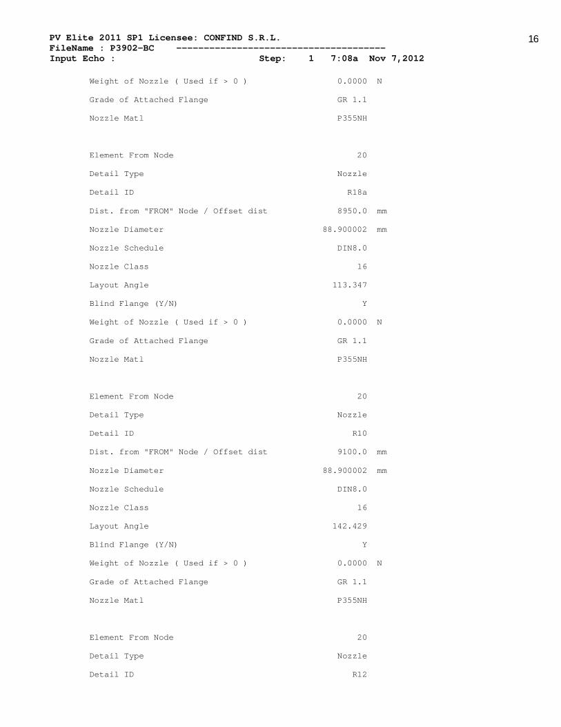
16
Weight of Nozzle ( Used if > 0 ) 0.0000 N
Grade of Attached Flange GR 1.1
Nozzle Matl P355NH
Element From Node 20
Detail Type Nozzle
Detail ID R18a
Dist. from "FROM" Node / Offset dist 8950.0 mm
Nozzle Diameter 88.900002 mm
Nozzle Schedule DIN8.0
Nozzle Class 16
Layout Angle 113.347
Blind Flange (Y/N) Y
Weight of Nozzle ( Used if > 0 ) 0.0000 N
Grade of Attached Flange GR 1.1
Nozzle Matl P355NH
Element From Node 20
Detail Type Nozzle
Detail ID R10
Dist. from "FROM" Node / Offset dist 9100.0 mm
Nozzle Diameter 88.900002 mm
Nozzle Schedule DIN8.0
Nozzle Class 16
Layout Angle 142.429
Blind Flange (Y/N) Y
Weight of Nozzle ( Used if > 0 ) 0.0000 N
Grade of Attached Flange GR 1.1
Nozzle Matl P355NH
Element From Node 20
Detail Type Nozzle
Detail ID R12

PV Elite 2011 SP1 Licensee: CONFIND S.R.L. FileName : P3902-BC -------------------------------------- Input Echo : Step: 1 7:08a Nov 7,2012
17
Dist. from "FROM" Node / Offset dist 8800.0 mm
Nozzle Diameter 88.900002 mm
Nozzle Schedule DIN8.0
Nozzle Class 16
Layout Angle 131.338
Blind Flange (Y/N) Y
Weight of Nozzle ( Used if > 0 ) 0.0000 N
Grade of Attached Flange GR 1.1
Nozzle Matl P355NH
Element From Node 20
Detail Type Nozzle
Detail ID R17a
Dist. from "FROM" Node / Offset dist 8650.0 mm
Nozzle Diameter 51. mm
Nozzle Schedule DIN12.5
Nozzle Class 40
Layout Angle 283.
Blind Flange (Y/N) N
Weight of Nozzle ( Used if > 0 ) 0.0000 N
Grade of Attached Flange GR 1.1
Nozzle Matl P285QH
Element From Node 20
Detail Type Nozzle
Detail ID R20
Dist. from "FROM" Node / Offset dist 8920.0 mm
Nozzle Diameter 88.900002 mm
Nozzle Schedule DIN8.0
Nozzle Class 16
Layout Angle 0.
Blind Flange (Y/N) Y
Weight of Nozzle ( Used if > 0 ) 0.0000 N

PV Elite 2011 SP1 Licensee: CONFIND S.R.L. FileName : P3902-BC -------------------------------------- Input Echo : Step: 1 7:08a Nov 7,2012
18
Grade of Attached Flange GR 1.1
Nozzle Matl P285QH
Element From Node 30
Element To Node 40
Element Type Elliptical
Description FUND ELIPSOIDAL 2
Distance "FROM" to "TO" 50.000 mm
Inside Diameter 3000.0 mm
Element Thickness 14.000 mm
Internal Corrosion Allowance 3.0000 mm
Nominal Thickness 14.000 mm
External Corrosion Allowance 0.0000 mm
Design Internal Pressure 0.6000 MPa
Design Temperature Internal Pressure 60 C
Design External Pressure 0.0000 MPa
Design Temperature External Pressure -20 C
Effective Diameter Multiplier 1.2
Material Name P355NH
Elliptical Head Factor 2.
Element From Node 30
Detail Type Nozzle
Detail ID GV1b
Dist. from "FROM" Node / Offset dist 0.0000 mm
Nozzle Diameter 508. mm
Nozzle Schedule DIN10.0
Nozzle Class 10
Layout Angle 0.
Blind Flange (Y/N) Y
Weight of Nozzle ( Used if > 0 ) 0.0000 N
Grade of Attached Flange GR 1.1
Nozzle Matl P355NH

PV Elite 2011 SP1 Licensee: CONFIND S.R.L. FileName : P3902-BC -------------------------------------- Input Echo : Step: 1 7:08a Nov 7,2012
19
Element From Node 30
Detail Type Nozzle
Detail ID R19
Dist. from "FROM" Node / Offset dist 850.00 mm
Nozzle Diameter 219.10001 mm
Nozzle Schedule DIN10.0
Nozzle Class 16
Layout Angle 180.
Blind Flange (Y/N) Y
Weight of Nozzle ( Used if > 0 ) 0.0000 N
Grade of Attached Flange GR 1.1
Nozzle Matl P355NH
Element From Node 30
Detail Type Nozzle
Detail ID R15
Dist. from "FROM" Node / Offset dist 700.00 mm
Nozzle Diameter 88.900002 mm
Nozzle Schedule DIN8.0
Nozzle Class 16
Layout Angle 90.
Blind Flange (Y/N) Y
Weight of Nozzle ( Used if > 0 ) 0.0000 N
Grade of Attached Flange GR 1.1
Nozzle Matl P355NH
Element From Node 30
Detail Type Nozzle
Detail ID R18b
Dist. from "FROM" Node / Offset dist 860.00 mm
Nozzle Diameter 88.900002 mm
Nozzle Schedule DIN8.0

PV Elite 2011 SP1 Licensee: CONFIND S.R.L. FileName : P3902-BC -------------------------------------- Input Echo : Step: 1 7:08a Nov 7,2012
20
Nozzle Class 16
Layout Angle 126.
Blind Flange (Y/N) Y
Weight of Nozzle ( Used if > 0 ) 0.0000 N
Grade of Attached Flange GR 1.1
Nozzle Matl P355NH
Element From Node 30
Detail Type Nozzle
Detail ID R16
Dist. from "FROM" Node / Offset dist 1100.0 mm
Nozzle Diameter 88.900002 mm
Nozzle Schedule DIN8.0
Nozzle Class 16
Layout Angle 141.
Blind Flange (Y/N) Y
Weight of Nozzle ( Used if > 0 ) 0.0000 N
Grade of Attached Flange GR 1.1
Nozzle Matl P355NH
Element From Node 30
Detail Type Nozzle
Detail ID R14
Dist. from "FROM" Node / Offset dist 1086.0 mm
Nozzle Diameter 88.900002 mm
Nozzle Schedule DIN8.0
Nozzle Class 16
Layout Angle 158.
Blind Flange (Y/N) Y
Weight of Nozzle ( Used if > 0 ) 0.0000 N
Grade of Attached Flange GR 1.1
Nozzle Matl P355NH

PV Elite 2011 SP1 Licensee: CONFIND S.R.L. FileName : P3902-BC -------------------------------------- Input Echo : Step: 1 7:08a Nov 7,2012
21
Element From Node 30
Detail Type Nozzle
Detail ID R13
Dist. from "FROM" Node / Offset dist 1011.0 mm
Nozzle Diameter 88.900002 mm
Nozzle Schedule DIN8.0
Nozzle Class 16
Layout Angle 81.
Blind Flange (Y/N) Y
Weight of Nozzle ( Used if > 0 ) 0.0000 N
Grade of Attached Flange GR 1.1
Nozzle Matl P285QH
PV Elite is a trademark of Intergraph CADWorx & Analysis Solutions, Inc. 2011

PV Elite 2011 SP1 Licensee: CONFIND S.R.L. FileName : P3902-BC -------------------------------------- XY Coordinate Calculations : Step: 2 7:08a Nov 7,2012
22
XY Coordinate Calculations
| | | | | |
From| To | X (Horiz.)| Y (Vert.) |DX (Horiz.)| DY (Vert.) |
| | mm | mm | mm | mm |
--------------------------------------------------------------
FUND ELIPS| 50.0000 | ... | 50.0000 | ... |
VIROLA| 10400.0 | ... | 10350.0 | ... |
FUND ELIPS| 10450.0 | ... | 50.0000 | ... |
PV Elite is a trademark of Intergraph CADWorx & Analysis Solutions, Inc. 2011

PV Elite 2011 SP1 Licensee: CONFIND S.R.L. FileName : P3902-BC -------------------------------------- Internal Pressure Calculations : Step: 3 7:08a Nov 7,2012
23
Element Thickness, Pressure, Diameter and Allowable Stress :
| | Int. Press | Nominal | Total Corr| Element | Allowable |
From| To | + Liq. Hd | Thickness | Allowance | Diameter | Stress(SE)|
| | MPa | mm | mm | mm | MPa |
---------------------------------------------------------------------------
FUND ELIPS| 0.6000 | 14.000 | 3.0000 | 3000.0 | 204.17 |
VIROLA| 0.6000 | 14.000 | 3.0000 | 3000.0 | 204.17 |
FUND ELIPS| 0.6000 | 14.000 | 3.0000 | 3000.0 | 204.17 |
Element Required Thickness and MAWP :
| | Design | M.A.W.P. | M.A.P. | Minimum | Required |
From| To | Pressure | Corroded | New & Cold | Thickness | Thickness |
| | MPa | MPa | MPa | mm | mm |
----------------------------------------------------------------------------
FUND ELIPS| 0.60000 | 1.09314 | 1.41195 | 14.0000 | 9.47391 |
VIROLA| 0.60000 | 1.48884 | 1.89677 | 14.0000 | 7.42332 |
FUND ELIPS| 0.60000 | 1.29354 | 1.68320 | 14.0000 | 8.87677 |
Minimum 1.093 1.412
MAWP: 1.093 MPa, limited by: FUND ELIPSOIDAL 1.
Internal Pressure Calculation Results :
European Std: EN 13445-3: 2009(E) Issue 1 (2009-07)
Elliptical Head From 10 To 20 P355NH at 60 C

PV Elite 2011 SP1 Licensee: CONFIND S.R.L. FileName : P3902-BC -------------------------------------- Internal Pressure Calculations : Step: 3 7:08a Nov 7,2012
24
FUND ELIPSOIDAL 1
Design Stress at Ambient Temperature = 204.174 MPa
Required thickness = 9.474 mm
Required thickness in the crown = 6.970 mm
This is an Elliptical Head
The Material is Carbon Steel which affects value of fb:
Buckling Strs at ope. fb = Yield/1.5 = 329.552 /1.5 = 219.701 MPa
Buckling Strs at amb. fb = Yield/1.5 = 355.012 /1.5 = 236.675 MPa
Ellipsoidal head find geometry for equiv. tori-head EN13445 Equation 7.5.4:
Pressure including hydro head P : 0.6000 MPa
Inside Head Diameter (new) Di : 3000.0000 mm
Head Thickness (new) e : 14.0000 mm
Head Aspect Ratio (new) Di/2h : 2.0000
Head Corrosion Allowance Internal ci : 3.0000 mm
Head Corrosion Allowance External co : 0.0000 mm
Joint Efficiency Z : 1.0000
hi = 0.5 * Di/AR + c = 0.5 * 3000.00/2.000+3.00 = 753.0000 mm
K = Di / (2 * hi) = 3006.000 / (2 * 753.000) = 1.9960
r = Di((0.5 / K) - 0.08) = 3006.000((0.5/1.996)-0.08) = 512.5200 mm
R = Di(0.44*K+ 0.02) = 3006.000 (0.44*1.996+0.02) = 2700.1306 mm
The nozzle is outside the 80% limit:
Nozzle corroded inside Diameter di : 225.1000 mm
Y = Min(e/R, 0.04) = Min(6.47391/2700.1306, 0.04) = 0.0023976
Z = Log10(1 / Y) = Log10(1 / 0.002) = 2.6202
X = r / Di = 512.5200 / 3006.0000 = 0.17050
N = 1.006 - 1 / ( 6.2+( 90 * Y )^4) )
= 1.006-1 / (6.2+( 90*0.0024)^4) = 0.84477
Beta01 = N( -0.1833*Z^3 + 1.0383*Z^2 - 1.2943*Z + 0.837 )
= 0.845 (-.1833*2.620^3 + 2.2124*2.620^2 - 3.2937*2.620 + 1.887
= 1.0785

PV Elite 2011 SP1 Licensee: CONFIND S.R.L. FileName : P3902-BC -------------------------------------- Internal Pressure Calculations : Step: 3 7:08a Nov 7,2012
25
Beta02 = max ( 0.95 * ( 0.56 - 1.94 * Y - 82.5 * Y^2), 0.5 )
= max ( 0.95 * ( 0.56 - 1.94 * 0.002 - 82.5 * 0.002^2), 0.5 )
= 0.5271
Beta = 10 ( ( 0.2 - X ) * Bets01 + ( X - 0.1 ) * Beta02
= 10 ( ( 0.2 - 0.1705 ) * 1.0785 + ( 0.1705 - 0.1 ) * 0.5271
= 0.6898
Thickness Due to Design Internal Pressure: e = Max(es, ey, eb) - para 7.5.3.2
Compute from Section 7.7.3 [Beta_k]:
V = Log10(1000 * P / S )
= Log10( 1000 * 0.600 / 204.174 ) = 0.4682
Note: Compute Beta_K using the Korbbogen equations.
A = 0.54 + 0.41 * V - 0.044 * V³
= 0.54 + 0.41 * 0.468 - 0.044 * 0.468³ = 0.7274
B = 7.77 - 4.53 * V + 0.744 * V²
= 7.77 - 4.53 * 0.468 + 0.744 * 0.468² = 5.8123
Beta_k = max ( A + B * di/De, 1.0 + 0.5 * B * di/De )
= max ( 0.727 + 5.812 * 225.100 /3028.000 , 1.0 +
0.3 * 5.812 * 225.100 /3028.000 ) = 1.2160
Thickness Due to Design Internal Pressure: e = Max(es, ey, eb) - para 7.5.3.2
Required Crown Thickness due to Internal Pressure, see Figure 7.5-3 [es]:
= P * R/( 2 * f * z - 0.5 * P )
= 0.600 * 2700.1 /( 2 * 204.174 * 1.00 - 0.5 * 0.600 )
= 3.9703 mm
ey = Beta*Beta_k*P(0.75*R+0.2*Di)/f
=1.216*0.690*0.600(0.75*2700.13+0.2*3006.00/
204.1738 = 6.4739 mm

PV Elite 2011 SP1 Licensee: CONFIND S.R.L. FileName : P3902-BC -------------------------------------- Internal Pressure Calculations : Step: 3 7:08a Nov 7,2012
26
eb = (0.75R+0.2Di)((P/111*fb)*(Di/r)0.825)1/1.5
= (0.75*2700.13+0.2*3006.00) *
(0.60/111 *219.70)(3006.00/512.52)0.825)1/1.5
= 5.8780 mm
Computed Head Thickness per EN13445 - 7.5.4:
= Max(es,eb,ey)+c+cext = Max(3.9703,5.8780,6.4739) + 3.0000 + 0.0000
= 6.4739 + 3.0000 +0.0000 = 9.4739 mm
The head is suitable for the design pressure.
Computed Stress at Design Pressure [Stres]:
= 112.048 MPa
Computed Maximum Allowable Working Pressure - Design [MAWP]:
MAWP - Phydro = 1.0931 - 0.0000 = 1.0931 MPa
Computed Maximum Pressure New and Cold [MAPNC]:
= 1.412 MPa
Uncorrected (for liquid) Hydrotest Pressure:
= 1.534 MPa
Elongation of the extreme fiber:
For a spun head per EN 13445-4 Para 9.2.1 [F]:
assuming the blank is 20% larger than the head diameter
= 100 * ln( 3633.600 /( 3000.000 - 2 * 14.000 ) ) = 19.161 %
For a segmented head per EN 13445-4 Para 9.2.5 [F]:
= 100 * e / R = 100 * 0.551 / 59.331 = 0.929 %
If F exceeds 5% PWHT may be required. Please refer
to EN 13445 Part 4 Table 9.4.1
Required Thickness of Straight Flange = 7.423 mm
Min. Des. Temp. per EN13445 Part 2: Thickness 14.000 mm at -20 C:
User entered Minum Design Temperature: -20.000 C
Note: The Component is NOT Post Weld Heat Treated.
Yield Value of the Component 355.0125 MPa
Selected Graph: B4.1-4 per EN13445-2 B4
Note: Computed Impact Test Temp. Tkt: -3 C.
Impact Testing is Required!

PV Elite 2011 SP1 Licensee: CONFIND S.R.L. FileName : P3902-BC -------------------------------------- Internal Pressure Calculations : Step: 3 7:08a Nov 7,2012
27
Cylindrical Shell From 20 To 30 P355NH at 60 C
VIROLA
Design Stress at Ambient Temperature = 204.174 MPa
Thickness due to internal pressure [e]:
= P * Di / ( 2 * f * z - P ) EN13445 Equation: 7.4.2:
= 0.60 * 3006.00 / ( 2 * 204.174 * 1.000 - 0.600 ) + c + cext
= 4.4233 + 3.0000 + 0.0000 = 7.4233 mm
The shell is suitable for the design pressure.
Maximum Working Pressure Hot and Corroded [MAWP]:
= ( 2 * f * ecor * z ) / (Di + ecor) - Phead
= ( 2 * 204.17 * 11.0000 * 1.000 ) / (3006.00 + 11.0000 )-0.00
= 1.489 MPa
Maximum Pressure New and Cold [MAPNC]:
= ( 2 * fa * e * z ) / ( D + e )
= ( 2 * 204.17 * 14.00 * 1.000 ) / ( 3000.00 + 14.00 )
= 1.897 MPa
Stress at Design Pressure [Stres]:
= P * ( Di + ecor ) /(2 * ecor * z)
= 0.600 * (3006.000 + 11.0000 ) / (2 * 11.0000 * 1.000 )
= 82.282 MPa
Uncorrected (for liquid) Hydrotest Pressure per 6.2.2 stress limitation:
= ( 2 * Ftest * e * z ) / (Di + e)
= ( 2 * 338.11 * 14.00 * 1.000 ) / ( 3000.00 + 14.00 )
= 3.141 MPa
Elongation of the extreme fiber per EN 13445-4 Para 9.2.2 [F]
= 50*Max(e, enom) / Rm = 50*Max(14.000 ,14.000 )/1508.500 = 0.464 %
Min. Des. Temp. per EN13445 Part 2: Thickness 14.000 mm at -20 C:
User entered Minum Design Temperature: -20.000 C
Note: The Component is NOT Post Weld Heat Treated.
Yield Value of the Component 355.0125 MPa
Selected Graph: B4.1-4 per EN13445-2 B4
Note: Computed Impact Test Temp. Tkt: -3 C.
Impact Testing is Required!

PV Elite 2011 SP1 Licensee: CONFIND S.R.L. FileName : P3902-BC -------------------------------------- Internal Pressure Calculations : Step: 3 7:08a Nov 7,2012
28
Elliptical Head From 30 To 40 P355NH at 60 C
FUND ELIPSOIDAL 2
Design Stress at Ambient Temperature = 204.174 MPa
Required thickness = 8.877 mm
Required thickness in the crown = 6.970 mm
This is an Elliptical Head
The Material is Carbon Steel which affects value of fb:
Buckling Strs at ope. fb = Yield/1.5 = 329.652 /1.5 = 219.768 MPa
Buckling Strs at amb. fb = Yield/1.5 = 355.012 /1.5 = 236.675 MPa
Ellipsoidal head find geometry for equiv. tori-head EN13445 Equation 7.5.4:
Pressure including hydro head P : 0.6000 MPa
Inside Head Diameter (new) Di : 3000.0000 mm
Head Thickness (new) e : 14.0000 mm
Head Aspect Ratio (new) Di/2h : 2.0000
Head Corrosion Allowance Internal ci : 3.0000 mm
Head Corrosion Allowance External co : 0.0000 mm
Joint Efficiency Z : 1.0000
hi = 0.5 * Di/AR + c = 0.5 * 3000.00/2.000+3.00 = 753.0000 mm
K = Di / (2 * hi) = 3006.000 / (2 * 753.000) = 1.9960
r = Di((0.5 / K) - 0.08) = 3006.000((0.5/1.996)-0.08) = 512.5200 mm
R = Di(0.44*K+ 0.02) = 3006.000 (0.44*1.996+0.02) = 2700.1306 mm
Y = Min(e/R, 0.04) = Min(5.87677/2700.1306, 0.04) = 0.0021765
Z = Log10(1 / Y) = Log10(1 / 0.002) = 2.6622
X = r / Di = 512.5200 / 3006.0000 = 0.17050
N = 1.006 - 1 / ( 6.2+( 90 * Y )^4) )
= 1.006-1 / (6.2+( 90*0.0022)^4) = 0.84475
Beta01 = N( -0.1833*Z^3 + 1.0383*Z^2 - 1.2943*Z + 0.837 )
= 0.845 (-.1833*2.662^3 + 2.2124*2.662^2 - 3.2937*2.662 + 1.887
= 1.0911
Beta02 = max ( 0.95 * ( 0.56 - 1.94 * Y - 82.5 * Y^2), 0.5 )
= max ( 0.95 * ( 0.56 - 1.94 * 0.002 - 82.5 * 0.002^2), 0.5 )
= 0.5276
Beta = 10 ( ( 0.2 - X ) * Bets01 + ( X - 0.1 ) * Beta02

PV Elite 2011 SP1 Licensee: CONFIND S.R.L. FileName : P3902-BC -------------------------------------- Internal Pressure Calculations : Step: 3 7:08a Nov 7,2012
29
= 10 ( ( 0.2 - 0.1705 ) * 1.0911 + ( 0.1705 - 0.1 ) * 0.5276
= 0.6938
Thickness Due to Design Internal Pressure: e = Max(es, ey, eb) - para 7.5.3.2
Required Crown Thickness due to Internal Pressure, see Figure 7.5-3 [es]:
= P * R/( 2 * f * z - 0.5 * P )
= 0.600 * 2700.1 /( 2 * 204.174 * 1.00 - 0.5 * 0.600 )
= 3.9703 mm
ey = Beta*P(0.75*R+0.2*Di)/f =0.69*0.6(0.75*2700.1+0.2*3006.0)/
204.1738 = 5.3550 mm
eb = (0.75R+0.2Di)((P/111*fb)*(Di/r)0.825)1/1.5
= (0.75*2700.13+0.2*3006.00) *
(0.60/111 *219.77)(3006.00/512.52)0.825)1/1.5
= 5.8768 mm
Computed Head Thickness per EN13445 - 7.5.4:
= Max(es,eb,ey)+c+cext = Max(3.9703,5.8768,5.3550) + 3.0000 + 0.0000
= 5.8768 + 3.0000 +0.0000 = 8.8768 mm
The head is suitable for the design pressure.
Actual stress at design pressure cannot be computed
because the thickness for buckling pressure controls.
Computed Maximum Allowable Working Pressure - Design [MAWP]:
MAWP - Phydro = 1.2935 - 0.0000 = 1.2935 MPa
Computed Maximum Pressure New and Cold [MAPNC]:
= 1.683 MPa
Uncorrected (for liquid) Hydrotest Pressure:
= 1.534 MPa
Elongation of the extreme fiber:
For a spun head per EN 13445-4 Para 9.2.1 [F]:
assuming the blank is 20% larger than the head diameter
= 100 * ln( 3633.600 /( 3000.000 - 2 * 14.000 ) ) = 19.161 %
For a segmented head per EN 13445-4 Para 9.2.5 [F]:
= 100 * e / R = 100 * 0.551 / 59.331 = 0.929 %
If F exceeds 5% PWHT may be required. Please refer to EN 13445 Part 4 Table 9.4.1
Required Thickness of Straight Flange = 7.423 mm

PV Elite 2011 SP1 Licensee: CONFIND S.R.L. FileName : P3902-BC -------------------------------------- Internal Pressure Calculations : Step: 3 7:08a Nov 7,2012
30
Min. Des. Temp. per EN13445 Part 2: Thickness 14.000 mm at -20 C:
User entered Minum Design Temperature: -20.000 C
Note: The Component is NOT Post Weld Heat Treated.
Yield Value of the Component 355.0125 MPa
Selected Graph: B4.1-4 per EN13445-2 B4
Note: Computed Impact Test Temp. Tkt: -3 C.
Impact Testing is Required!
Hydrostatic Test Pressure Results:
Note: The Hydrotest Pressure Derivation is an Iterative Process
Limited by: Ellipse Head FUND ELIPSOIDAL
Hydrotest pressure is based upon stress (ftest) in the weakest element:
Note: 1.5 / 1.05 = 1.429, The PED requirement is 1.43
ftest = Yield Stress / 1.05
= 355.012 / 1.05 = 338.107 MPa
Test Pressure = Calc Test Press - Liquid Head
= 1.534 - 0.029 = 1.504 MPa
Elements Suitable for Internal Pressure.
PV Elite is a trademark of Intergraph CADWorx & Analysis Solutions, Inc. 2011

PV Elite 2011 SP1 Licensee: CONFIND S.R.L. FileName : P3902-BC -------------------------------------- Element and Detail Weights : Step: 5 7:08a Nov 7,2012
31
Element and Detail Weights
| | Element | Element | Corroded | Corroded | Extra due |
From| To | Metal Wgt. | ID Volume |Metal Wgt. | ID Volume | Misc % |
| | kg | cm3 | kg | cm3 | kg |
---------------------------------------------------------------------------
10| 20| 1240.58 | 3.888E+06 | 974.741 | 3.911E+06 | ... |
20| 30| 10756.8 | 73.17E+06 | 8460.26 | 73.47E+06 | ... |
30| 40| 1245.35 | 3.888E+06 | 978.486 | 3.911E+06 | ... |
---------------------------------------------------------------------------
Total 13242 80949800.00 10413 81288112.00 0
Weight of Details
| | Weight of | X Offset, | Y Offset, |
From|Type| Detail | Dtl. Cent. |Dtl. Cent. | Description
| | kg | mm | mm |
-------------------------------------------------
10|Nozl| 88.1762 | -750.000 | ... | GV1a
10|Nozl| 22.4052 | -509.902 | ... | R1
10|Nozl| 18.7288 | -450.000 | ... | R3
20|Sadl| 851.391 | 850.000 | 1736.00 | left Sdl
20|Sadl| 851.391 | 9600.00 | 1736.00 | right sdl
20|Nozl| 88.1762 | 500.000 | 1754.00 | GV2a
20|Nozl| 88.1762 | 7950.00 | 1754.00 | GV2b
20|Nozl| 1.07926 | 3860.00 | 1525.50 | M1
20|Nozl| 17.3716 | 6940.00 | 1584.15 | R8
20|Nozl| 17.3716 | 9220.00 | 1584.15 | R2
20|Nozl| 24.8760 | 9950.00 | 1609.55 | R6
20|Nozl| 18.5834 | 250.000 | 1584.15 | R7c
20|Nozl| 18.5834 | 2700.00 | 1584.15 | R7b
20|Nozl| 18.5834 | 7650.00 | 1584.15 | R7a
20|Nozl| 20.7100 | 8910.00 | 1609.55 | R5
20|Nozl| 17.3716 | 10100.0 | 1584.15 | R4
20|Nozl| 3.10788 | 8650.00 | 1525.50 | R17b
20|Nozl| 0.44871 | 10240.0 | 1525.50 | R17d

PV Elite 2011 SP1 Licensee: CONFIND S.R.L. FileName : P3902-BC -------------------------------------- Element and Detail Weights : Step: 5 7:08a Nov 7,2012
32
20|Nozl| 8.76849 | 9100.00 | 1544.45 | R11
20|Nozl| 5.35114 | 8800.00 | 1544.45 | R9
20|Nozl| 6.91690 | 8950.00 | 1544.45 | R18a
20|Nozl| 6.45956 | 9100.00 | 1544.45 | R10
20|Nozl| 6.10067 | 8800.00 | 1544.45 | R12
20|Nozl| 2.45844 | 8650.00 | 1525.50 | R17a
20|Nozl| 8.76849 | 8920.00 | 1544.45 | R20
30|Nozl| 88.6208 | 800.000 | ... | GV1b
30|Nozl| 28.8188 | 667.960 | ... | R19
30|Nozl| 5.74814 | 713.325 | 700.000 | R15
30|Nozl| 7.02170 | 664.492 | 695.755 | R18b
30|Nozl| 7.02170 | 559.902 | 692.252 | R16
30|Nozl| 7.02170 | 567.350 | 406.823 | R14
30|Nozl| 4.26533 | 604.048 | 998.553 | R13
Total Weight of Each Detail Type
Total Weight of Saddles 1702.8
Total Weight of Nozzles 657.1
---------------------------------------------------------------
Sum of the Detail Weights 2359.9 kg
Weight Summary
Fabricated Wt. - Bare Weight W/O Removable Internals 15602.6 kg
Shop Test Wt. - Fabricated Weight + Water ( Full ) 96503.0 kg
Shipping Wt. - Fab. Wt + Rem. Intls.+ Shipping App. 15602.6 kg
Erected Wt. - Fab. Wt + Rem. Intls.+ Insul. (etc) 15602.6 kg
Ope. Wt. no Liq - Fab. Wt + Intls. + Details + Wghts. 15602.6 kg
Operating Wt. - Empty Wt + Operating Liq. Uncorroded 15602.6 kg
Oper. Wt. + CA - Corr Wt. + Operating Liquid 12773.4 kg
Field Test Wt. - Empty Weight + Water (Full) 96503.0 kg
Note: The Corroded Weight and thickness are used in the Horizontal
Vessel Analysis (Ope Case) and Earthquake Load Calculations.

PV Elite 2011 SP1 Licensee: CONFIND S.R.L. FileName : P3902-BC -------------------------------------- Element and Detail Weights : Step: 5 7:08a Nov 7,2012
33
Outside Surface Areas of Elements
| | Surface |
From| To | Area |
| | mm² |
----------------------------
10| 20| 10.41E+06 |
20| 30| 98.46E+06 |
30| 40| 10.41E+06 |
-------------------------------
Total 119285824.000 mm²
PV Elite is a trademark of Intergraph CADWorx & Analysis Solutions, Inc. 2011

PV Elite 2011 SP1 Licensee: CONFIND S.R.L. FileName : P3902-BC -------------------------------------- Nozzle Flange MAWP : Step: 6 7:08a Nov 7,2012
34
Nozzle Flange MAWP Results :
Nozzle ----- Flange Rating
Description Operating Ambient Temperature Class Grade|Group
MPa MPa C
----------------------------------------------------------------------------
GV1a 6895.0 6895.0 60 10 GR 1.1
R1 6895.0 6895.0 60 16 GR 1.1
R3 6895.0 6895.0 60 16 GR 1.1
GV2a 6895.0 6895.0 60 10 GR 1.1
GV2b 6895.0 6895.0 60 10 GR 1.1
R8 6895.0 6895.0 60 16 GR 1.1
R2 6895.0 6895.0 60 16 GR 1.1
R6 6895.0 6895.0 60 16 GR 1.1
R7c 6895.0 6895.0 60 40 GR 1.1
R7b 6895.0 6895.0 60 40 GR 1.1
R7a 6895.0 6895.0 60 40 GR 1.1
R5 6895.0 6895.0 60 16 GR 1.1
R4 6895.0 6895.0 60 16 GR 1.1
R17b 6895.0 6895.0 60 40 GR 1.1
R17d 6895.0 6895.0 60 40 GR 1.1
R11 6895.0 6895.0 60 16 GR 1.1
R9 6895.0 6895.0 60 16 GR 1.1
R18a 6895.0 6895.0 60 16 GR 1.1
R10 6895.0 6895.0 60 16 GR 1.1
R12 6895.0 6895.0 60 16 GR 1.1
R17a 6895.0 6895.0 60 40 GR 1.1
R20 6895.0 6895.0 60 16 GR 1.1
GV1b 6895.0 6895.0 60 10 GR 1.1
R19 6895.0 6895.0 60 16 GR 1.1
R15 6895.0 6895.0 60 16 GR 1.1
R18b 6895.0 6895.0 60 16 GR 1.1
R16 6895.0 6895.0 60 16 GR 1.1
R14 6895.0 6895.0 60 16 GR 1.1

PV Elite 2011 SP1 Licensee: CONFIND S.R.L. FileName : P3902-BC -------------------------------------- Nozzle Flange MAWP : Step: 6 7:08a Nov 7,2012
35
R13 6895.0 6895.0 60 16 GR 1.1
----------------------------------------------------------------------------
Minimum Rating 6895.000 6895.000 MPa
Note: ANSI Ratings are per ANSI/ASME B16.5 2003 Edition
PV Elite is a trademark of Intergraph CADWorx & Analysis Solutions, Inc. 2011

PV Elite 2011 SP1 Licensee: CONFIND S.R.L. FileName : P3902-BC -------------------------------------- Wind Load Calculation : Step: 7 7:08a Nov 7,2012
36
Wind Analysis Results
User Entered Importance Factor is 1.000
Gust Factor (Gh, Gbar) Static 1.239
Shape Factor (Cf) for the Vessel is 0.546
User Entered Basic Wind Speed 112.7 km/hr
Exposure Category C
Table Lookup Value Alpha from Table C6 7.0000
Table Lookup Value Zg from Table C6 900.0000
Table Lookup Value Do from Table C6 0.0050
Wind Load Results per ASCE-7 93:
Sample Calculation for the First Element:
Rougness Factor = 1.000
Values [cf1] and [cf2]
Because RoughFact = 1 and DQZ > 2.5 and H/D < 7.0
Interpolating to find the final cf:
Because H / D < 7.0
CF = CF1 + (CF2-CF1)*( H/D - 1) / (7 - 1)
= 0.500 + (0.600 -0.500 )*( 3.758 - 1) / (7 - 1)
= 0.546
Value of Alpha, Zg is taken from Table C6-2 [Alpha, Zg]
For Exposure Category C:
Alpha = 7.000 , Zg = 274320.000 mm
Height of Interest for First Element [z]
= Centroid Hgt + Base Height
= 2000.000 + 0.000 = 2000.000 mm
but: z = Max(4572.000 , 2000.000 ) = 4572.000 mm
Note: Because z < 15 feet, use 15 feet to compute kz.
Velocity Pressure Coefficient [kZ]:
= 2.58( z/zg )2/Alpha : z is Elevation of First Element
= 2.58( 4572.000 /900 )2/7.0
= 0.801
Determine if Static or Dynamic Gust Factor Applies

PV Elite 2011 SP1 Licensee: CONFIND S.R.L. FileName : P3902-BC -------------------------------------- Wind Load Calculation : Step: 7 7:08a Nov 7,2012
37
Height to Diameter ratio :
= Maximum Height(length)^2 / Sum of Area of the Elements
= 11214.001 (^2) / 33459536
= 3.758
Vibration Frequency = 33.000 Hz
Because H/D < 5 And Frequency > 1.0: Static Analysis Implemented
The following two calculations allow for any user units
Compute [tz]
= 2.35 * Sqrt(DO / VesselHtg/30(feet)1/Alpha
= 2.35 * Sqrt(0.005 / 11214.001 )1/9144.000
= 0.161
Compute [Gh]
= 0.65 + 3.65 * tz
= 0.65 + 3.65 * 0.161 = 1.239
Wind Pressure - (performed in Imperial Units) [qz]
Importance Factor: I = 1.000
Wind Speed = 112.651 km/hr Converts to 70.000 mph
qz = 0.00256 * kZ * (I * Vr)²
= 0.00256 * 0.801 *(1.000 * 70.000 )² = 10.046 psf
Converts to: 49.052 kg/m²
Force on the First Element [Fz]
= qz * Gh * CF * Wind Area
= 49.052 * 1.239 * 0.546 * 1998613
= 650.357 N
Element z GH Area qz Force
mm mm² kg/m² N
------------------------------------------------------------------------
FUND ELIPSOIDAL 2000.0 1.239 1998613.9 49.1 650.4
VIROLA 2000.0 1.239 37607764.0 49.1 12237.7
FUND ELIPSOIDAL 2000.0 1.239 1998613.9 49.1 650.4

PV Elite 2011 SP1 Licensee: CONFIND S.R.L. FileName : P3902-BC -------------------------------------- Wind Load Calculation : Step: 7 7:08a Nov 7,2012
38
Wind Load Calculation
| | Wind | Wind | Wind | Height | Element |
From| To | Height | Diameter | Area | Factor | Wind Load |
| | mm | mm | mm² | kg/m² | N |
---------------------------------------------------------------------------
10| 20| 2000.00 | 3633.60 | 1.999E+06 | 49.0518 | 650.357 |
20| 30| 2000.00 | 3633.60 | 37.61E+06 | 49.0518 | 12237.7 |
30| 40| 2000.00 | 3633.60 | 1.999E+06 | 49.0518 | 650.357 |
PV Elite is a trademark of Intergraph CADWorx & Analysis Solutions, Inc. 2011

PV Elite 2011 SP1 Licensee: CONFIND S.R.L. FileName : P3902-BC -------------------------------------- Earthquake Load Calculation : Step: 8 7:08a Nov 7,2012
39
Note: Loads multiplied by the Scalar multiplier value of 0.7143
Earthquake Analysis Results per UBC 1997
The UBC Zone Factor for the Vessel is ............. 0.0000
The Importance Factor as Specified by the User is . 1.250
The UBC Force Factor as Specified by the User is .. 2.000
The UBC Total Weight (W) for the Vessel is ........ 125255.5 N
The UBC Total Shear (V) for the Vessel is ......... 28183.1 N
The UBC Seismic Coefficient Value Ca is ........... 0.360
The UBC Seismic Coefficient Value Cv is ........... 0.840
Note: The base shear printed above has been modified
by the user defined Earthquake scalar.
Calculation Steps for Computing the design Base Shear (V) per UBC 1997
Computation of V per equation (34-1):
V = 0.7 * Ca * I * W
V = 0.7 * 0.360 * 1.250 * 125255
V = 39455.5 N
Computation of V per equation (30-5):
V = 2.5 * Ca * I * W / R
V = 2.5 * 0.360 * 1.25 * 125255 / 2.000
V = 70456.2 N
The computed base shear is the minimum of V from 34-1 and 30-5.
Computation of V per equation (34-2), minimum V. V cannot be less than
this value !
V = 0.56 * Ca * I * W
V = 0.56 * 0.360 * 1.250 * 125255
V = 31564.4 N
Total Adjusted Base Shear V:
= V * Scalar Multiplier = 39455.5 * 0.7143 = 28183.1 N
Next Sum the earthquake weights times their heights (wi*hi):
Current Sum = Prev. Sum + Wght 25051. * Hght 1500.000 = 37591892.
Current Sum = Prev. Sum + Wght 25051. * Hght 1500.000 = 75183784.

PV Elite 2011 SP1 Licensee: CONFIND S.R.L. FileName : P3902-BC -------------------------------------- Earthquake Load Calculation : Step: 8 7:08a Nov 7,2012
40
Current Sum = Prev. Sum + Wght 25051. * Hght 1500.000 = 112775680.
Current Sum = Prev. Sum + Wght 25051. * Hght 1500.000 = 150367568.
Current Sum = Prev. Sum + Wght 25051. * Hght 1500.000 = 187959472.
Compute the load at each level based on equation 30-15 and multiply
by the load case scalar. The sum will be the total adjusted shear.
Fx = ( V * wx * hx / ( sum of ( wi * hi ))) * EqFact
Fx = [(39455.) * 25051. * 1500.000 / 187959472.]*0.7143 = 5637.
Fx = [(39455.) * 25051. * 1500.000 / 187959472.]*0.7143 = 5637.
Fx = [(39455.) * 25051. * 1500.000 / 187959472.]*0.7143 = 5637.
Fx = [(39455.) * 25051. * 1500.000 / 187959472.]*0.7143 = 5637.
Fx = [(39455.) * 25051. * 1500.000 / 187959472.]*0.7143 = 5637.
Earthquake Load Calculation
| | Earthquake | Earthquake | Element |
From| To | Height | Weight | Ope Load |
| | mm | N | N |
-------------------------------------------------
10| 20| 1500.00 | 25051.1 | 5636.61 |
20|Sadl| 1500.00 | 25051.1 | 5636.61 |
Sadl| 30| 1500.00 | 25051.1 | 5636.61 |
20| 30| 1500.00 | 25051.1 | 5636.61 |
30| 40| 1500.00 | 25051.1 | 5636.61 |
PV Elite is a trademark of Intergraph CADWorx & Analysis Solutions, Inc. 2011

PV Elite 2011 SP1 Licensee: CONFIND S.R.L. FileName : P3902-BC -------------------------------------- Center of Gravity Calculation : Step: 9 7:08a Nov 7,2012
41
Shop/Field Installation Options :
Note : The CG is computed from the first Element From Node
Center of Gravity of Saddles 5275.000 mm
Center of Gravity of Nozzles 5864.705 mm
Center of Gravity of Bare Shell New and Cold 5227.023 mm
Center of Gravity of Bare Shell Corroded 5227.021 mm
Vessel CG in the Operating Condition 5266.221 mm
Vessel CG in the Fabricated (Shop/Empty) Condition 5259.114 mm
PV Elite is a trademark of Intergraph CADWorx & Analysis Solutions, Inc. 2011

PV Elite 2011 SP1 Licensee: CONFIND S.R.L. FileName : P3902-BC -------------------------------------- Horizontal Vessel Analysis (Ope.) : Step: 10 7:08a Nov 7,2012
42
ASME Horizontal Vessel Analysis: Stresses for the Left Saddle
(per ASME Sec. VIII Div. 2 based on the Zick method.)
Horizontal Vessel Stress Calculations : Operating Case
Input and Calculated Values:
Vessel Mean Radius Rm 1508.50 mm
Stiffened Vessel Length per 4.15.6 L 10450.00 mm
Distance from Saddle to Vessel tangent a 685.00 mm
Saddle Width b 400.00 mm
Saddle Bearing Angle theta 120.00
Wear Plate Width b1 500.00 mm
Wear Plate Bearing Angle theta1 127.00
Wear Plate Thickness tr 14.0 mm
Wear Plate Allowable Stress Sr 204.17 MPa
Inside Depth of Head h2 753.00 mm
Shell Allowable Stress used in Calculation 204.17 MPa
Head Allowable Stress used in Calculation 204.17 MPa
Circumferential Efficiency in Plane of Saddle 1.00
Circumferential Efficiency at Mid-Span 1.00
Saddle Force Q, Operating Case 86763.61 N
Horizontal Vessel Analysis Results: Actual Allowable
-------------------------------------------------------------------
Long. Stress at Top of Midspan 39.18 204.17 MPa
Long. Stress at Bottom of Midspan 43.10 204.17 MPa
Long. Stress at Top of Saddles 41.17 204.17 MPa
Long. Stress at Bottom of Saddles 41.11 204.17 MPa
Tangential Shear in Shell 4.60 163.34 MPa
Tangential Shear in Head 4.60 163.34 MPa
Circ. Stress at Horn of Saddle 4.62 255.22 MPa
Addl. Stress in Head as Stiffener 83.92 255.22 MPa
Circ. Compressive Stress in Shell 1.00 204.17 MPa
Intermediate Results: Saddle Reaction Q due to Wind or Seismic

PV Elite 2011 SP1 Licensee: CONFIND S.R.L. FileName : P3902-BC -------------------------------------- Horizontal Vessel Analysis (Ope.) : Step: 10 7:08a Nov 7,2012
43
Saddle Reaction Force due to Wind Ft [Fwt]:
= Ftr * ( Ft/Num of Saddles + Z Force Load ) * B / E
= 3.00 * ( 13538.4 /2 + 0 ) * 2000.0000 / 2612.7986
= 15544.8 N
Saddle Reaction Force due to Wind Fl or Friction [Fwl]:
= Max( Fl, Friction Load, Sum of X Forces) * B / Ls
= Max( 4156.52 , 0.00 , 0 ) * 2000.0000 / 8750.0010
= 950.1 N
Saddle Reaction Force due to Earthquake Fl or Friction [Fsl]:
= Max( Fl, Friction Force, Sum of X Forces ) * B / Ls
= Max( 28183.05 , 0.00 , 0 ) * 2000.0000 / 8750.0010
= 6441.8 N
Saddle Reaction Force due to Earthquake Ft [Fst]:
= Ftr * ( Ft/Num of Saddles + Z Force Load ) * B / E
= 3.00 * ( 28183 /2 + 0 ) * 2000.0000 / 2612.7986
= 32359.6 N
Load Combination Results for Q + Wind or Seismic [Q]:
= Saddle Load + Max( Fwl, Fwt, Fsl, Fst )
= 54403 + Max( 950 , 15544 , 6441 , 32359 )
= 86763.6 N
Summary of Loads at the base of this Saddle:
Vertical Load (including saddle weight) 95112.34 N
Transverse Shear Load Saddle 14091.53 N
Longitudinal Shear Load Saddle 28183.05 N
Formulas and Substitutions for Horizontal Vessel Analysis:
Note: Wear Plate is Welded to the Shell, k = 0.1
The Computed K values from Table 4.15.1:
K1 = 0.1066 K2 = 1.1707 K3 = 0.8799 K4 = 0.4011
K5 = 0.7603 K6 = 0.0529 K7 = 0.0132 K8 = 0.3405
K9 = 0.2711 K10 = 0.0581 K1* = 0.1923 K6p = 0.0472
K7P = 0.0118
The suffix 'p' denotes the values for a wear plate if it exists.

PV Elite 2011 SP1 Licensee: CONFIND S.R.L. FileName : P3902-BC -------------------------------------- Horizontal Vessel Analysis (Ope.) : Step: 10 7:08a Nov 7,2012
44
Note: Dimension a is less than Rm/2.
Moment per Equation 4.15.3 [M1]:
= -Q*a [1 - (1- a/L + (R²-h2²)/(2a*L))/(1+(4h2)/3L)]
= -86763*685.00[1-(1-685.00/10450.00+(1508.500²-753.000²)/
(2*685.00*10450.00))/(1+(4*753.00)/(3*10450.00))]
= -2293745.0 N-mm
Moment per Equation 4.15.4 [M2]:
= Q*L/4(1+2(R²-h2²)/(L²))/(1+(4h2)/( 3L))-4a/L
= 86763*10450/4(1+2(1508²-753²)/(10450²))/(1+(4*753)/
(3*10450))-4*684/10450
= 153901664.0 N-mm
Longitudinal Stress at Top of Shell (4.15.6) [Sigma1]:
= P * Rm/(2t) - M2/(pi*Rm²t)
= 0.60 * 1508.500 /(2*11.00 ) - .15390E+09/(pi*1508.5²*11.00 )
= 39.18 MPa
Longitudinal Stress at Bottom of Shell (4.15.7) [Sigma2]:
= P * Rm/(2t) + M2/(pi * Rm² * t)
= 0.60 * 1508.500 /(2 * 11.00 ) + .15390E+09/(pi * 1508.5² * 11.00 )
= 43.10 MPa
Longitudinal Stress at Top of Shell at Support (4.15.8) [Sigma3]:
= P * Rm/(2t) - M1/(pi * Rm² * t)
= 0.60 * 1508.500 /(2 * 11.00 ) - -2293745.0/(pi * 1508.5² * 11.00 )
= 41.17 MPa
Longitudinal Stress at bottom of Shell at Support (4.15.9) [Sigma4]:
= P * Rm/(2t) + M1/(pi*Rm²t)
= 0.60 * 1508.500 /(2*11.00 ) + -2293745.0/(pi*1508.5²*11.00 )
= 41.11 MPa
Maximum Shear Force in the Saddle (4.15.5) [T]:
= Q(L-2a)/(L+(4*h2/3))
= 86763 ( 10450.00 - 2 * 685.00 )/(10450.00 + ( 4 * 753.00 /3))
= 68780.7 N
Shear Stress in the shell no rings, stiffened (4.15.15) [tau3]:
= K3 * Q / ( Rm * t )

PV Elite 2011 SP1 Licensee: CONFIND S.R.L. FileName : P3902-BC -------------------------------------- Horizontal Vessel Analysis (Ope.) : Step: 10 7:08a Nov 7,2012
45
= 0.8799 * 86763 / ( 1508.5000 * 11.0000 )
= 4.60 MPa
Shear Stress in the head, shell stiffened (4.15.16) [tau3*]:
= K3 * Q / ( Rm * th )
= 0.8799 * 86763 / ( 1508.5000 * 11.0000 )
= 4.60 MPa
Membrane stress in the head as a stiffener (4.15.18) [sigma5]:
= K4 * Q/(Rm*th) + ((P*Ri)/(2*th)) * (Ri/h2)
= 0.4011 * 86763 /(1508.50 * 11.000 ) +
((0.60 * 1503.00 )/(2 * 11.000 ))*(1503.00 / 753.00 )
= 83.92 MPa
Decay Length (4.15.22) [x1,x2]:
= 0.78 * sqrt( Rm * t )
= 0.78 * sqrt( 1508.500 * 11.000 )
= 100.476 mm
Circumferential Stress in shell, no rings (4.15.23) [sigma6]:
= -K5 * Q * k / ( t * ( b + X1 + X2 ) )
= -0.7603 * 86763 * 0.1 / ( 11.000 * ( 400.00 + 100.48 + 100.48 ) )
= -1.00 MPa
Effective reinforcing plate width (4.15.1) [B1]:
= min( b + 1.56 * sqrt( Rm * t ), 2a )
= min( 400.00 + 1.56 * sqrt( 1508.500 * 11.000 ), 2 * 685.000 )
= 600.95 mm
Wear Plate/Shell Stress ratio (4.15.29) [eta]:
= min( Sr/S, 1 )
= min( 204.174 / 204.174 , 1 )
= 1.0000
Circumferential Stress at wear plate (4.15.26) [sigma6,r]:
= -K5 * Q * k / ( B1( t + eta * tr ) )
= -0.7603 * 86763 * 0.1 / ( 600.953 ( 11.000 + 1.000 * 14.000 ) )
= -0.44 MPa
Circ. Comp. Stress at Horn of Saddle, L<8Rm (4.15.28) [sigma7,r*]:
= -Q/(4(t+eta*tr)b1) - 12*K7*Q*Rm/(L(t+eta*tr)²)

PV Elite 2011 SP1 Licensee: CONFIND S.R.L. FileName : P3902-BC -------------------------------------- Horizontal Vessel Analysis (Ope.) : Step: 10 7:08a Nov 7,2012
46
= -86763 /(4(11.000 + 1.000 * 14.000 )600.953 ) -
12*0.013*86763*1508.500/(10450.00(11.000+1.000*14.000)²)
= -4.62 MPa
Results for Vessel Ribs, Web and Base:
Baseplate Length Bplen 2400.0000 mm
Baseplate Thickness Bpthk 20.0000 mm
Baseplate Width Bpwid 400.0000 mm
Number of Ribs ( inc. outside ribs ) Nribs 4
Rib Thickness Ribtk 20.0000 mm
Web Thickness Webtk 20.0000 mm
Web Location Webloc Center
Moment of Inertia of Saddle - Lateral Direction
Y A AY Io
Shell 6. 7706. 42385. 310826.
Wearplate 18. 7000. 126000. 2382331.
Web 227. 8060. 1825590. 522580448.
BasePlate 438. 8000. 3504000. 1535017472.
Totals 688. 30766. 5497976. 2060291072.
Value C1 = Sumof(Ay)/Sumof(A) = 179. mm
Value I = Sumof(Io) - C1*Sumof(Ay) = 1077801472. mm**4
Value As = Sumof(A) - Ashell = 23060. mm²
K1 = (1+Cos(beta)-.5*Sin(beta)² )/(pi-beta+Sin(beta)*Cos(beta)) = 0.2035
Fh = K1 * Q = 0.2035 * 86763.609 = 17658.2793 N
Tension Stress, St = ( Fh/As ) = 0.7658 MPa
Allowed Stress, Sa = 0.6 * Yield Str = 143.9676 MPa
d = B - R*Sin(theta) / theta = 708.0291 mm
Bending Moment, M = Fh * d = 12507644.0000 N-mm
Bending Stress, Sb = ( M * C1 / I ) = 2.0731 MPa
Allowed Stress, Sa = 2/3 * Yield Str = 159.9640 MPa
Minimum Thickness of Baseplate per Moss :
= ( 3 * ( Q + Saddle_Wt ) * BasePlateWidth / ( 4 * BasePlateLength *
AllStress ))½
= ( 3 * (86763 + 8348 ) * 400.00 / ( 4 * 2400.000 * 159.964 ))½

PV Elite 2011 SP1 Licensee: CONFIND S.R.L. FileName : P3902-BC -------------------------------------- Horizontal Vessel Analysis (Ope.) : Step: 10 7:08a Nov 7,2012
47
= 8.621 mm
Calculation of Axial Load, Intermediate Values and Compressive Stress
Effective Baseplate Length [e]:
= ( Bplen - Clearance ) / ( Nribs - 1)
= ( 2400.0000 - 25.4 ) / ( 4 - 1 ) = 791.5333 mm
Baseplate Pressure Area [Ap]:
= e * Bpwid / 2
= 791.5333 * 400.0000 / 2 = 0.2E+06 mm²
Axial Load [P]:
= Ap * Bp
= 158306.7 * 0.09 = 14307.6 N
Area of the Rib and Web [Ar]:
= ( Bpwid - Clearance - Webtk ) * Ribtk + e/2 * Webtk
= ( 400.000 - 25.4 - 20.000 ) * 20.000 + 791.5333 /2 * 20.000
= 15007.332 mm²
Compressive Stress [Sc]:
= P/Ar
= 14307.6 / 15007.3320 = 0.9535 MPa
Check of Outside Ribs:
Inertia of Saddle, Outer Ribs - Longitudinal Direction
Y A AY Ay² Io
Rib 200.0 7346.0 1469200.0 0.0 96825736.0
Web 200.0 7915.3 1583066.5 0.0 527688.2
Values 200.0 15261.3 3052266.5 0.0 97353424.0
Bending Moment [Rm]:
= Fl /( 2 * Bplen ) * e * rl / 2
= 28183.1 /( 2 * 2400.00 ) * 791.533 * 1194.00 / 2
= 2775661 N-mm
KL/R < Cc ( 14.8245 < 128.2550 ) per AISC E2-1
Sca = (1-(Klr)²/(2*Cc²))*Fy/(5/3+3*(Klr)/(8*Cc)-(Klr³)/(8*Cc³)
Sca = ( 1-( 14.82 )²/(2 * 128.25² )) * 239 /
( 5/3+3*(14.82 )/(8* 128.25 )-( 14.82³)/(8*128.25³)
Sca = 139.40 MPa

PV Elite 2011 SP1 Licensee: CONFIND S.R.L. FileName : P3902-BC -------------------------------------- Horizontal Vessel Analysis (Ope.) : Step: 10 7:08a Nov 7,2012
48
AISC Unity Check on Outside Ribs ( must be <= 1.0 )
Check = Sc/Sca + (Rm/Z)/Sba
Check = 0.95 / 139.40 + (2775661 /486767.094) / 159.96
Check = 0.04
Check of Inside Ribs
Inertia of Saddle, Inner Ribs - Axial Direction
Y A AY Ay² Io
Rib 187.3 7092.0 1328331.4 0.0 87609584.0
Web 187.3 15830.7 2965083.8 0.0 527688.2
Values 187.3 22922.7 4293415.0 0.0 88137272.0
KL/R < Cc ( 7.6626 < 128.2550 ) per AISC E2-1
Sca = (1-(Klr)²/(2*Cc²))*Fy/(5/3+3*(Klr)/(8*Cc)-(Klr³)/(8*Cc³)
Sca = ( 1-( 7.66 )²/(2 * 128.25² )) * 239 /
( 5/3+3*(7.66 )/(8* 128.25 )-( 7.66³)/(8*128.25³)
Sca = 141.81 MPa
AISC Unity Check on Inside Ribs ( must be <= 1.0 )
Check = Sc/Sca + (Rm/Z)/Sba
Check = 1.25 / 141.81 + ( 2209106 /470567.375) / 159.96
Check = 0.04
Input Data for Base Plate Bolting Calculations:
Total Number of Bolts per BasePlate Nbolts 4
Total Number of Bolts in Tension/Baseplate Nbt 4
Bolt Material Specification C45E N
Bolt Allowable Stress Stba 113.34 MPa
Bolt Corrosion Allowance Bca 0.0000 mm
Distance from Bolts to Edge Edgedis 99.9998 mm
Nominal Bolt Diameter Bnd 30.0000 mm
Thread Series Series TEMA Metric
BasePlate Allowable Stress S 204.17 MPa
Area Available in a Single Bolt BltArea 502.9650 mm²
Saddle Load QO (Weight) QO 62752.7 N
Saddle Load QL (Wind/Seismic contribution) QL 6441.8 N

PV Elite 2011 SP1 Licensee: CONFIND S.R.L. FileName : P3902-BC -------------------------------------- Horizontal Vessel Analysis (Ope.) : Step: 10 7:08a Nov 7,2012
49
Maximum Transverse Force Ft 14091.5 N
Maximum Longitudinal Force Fl 28183.1 N
Saddle Bolted to Steel Foundation No
Bolt Area Calculation per Dennis R. Moss
Bolt Area Requirement Due to Longitudinal Load [Bltarearl]:
= 0.0 (QO > QL --> No Uplift in Longitudinal direction)
Bolt Area due to Shear Load [Bltarears]:
= Fl / (Stba * Nbolts)
= 28183.05 / (113.34 * 4.00 )
= 62.1718 mm²
Bolt Area due to Transverse Load
Moment on Baseplate Due to Transverse Load [Rmom]:
= B * Ft + Sum of X Moments
= 2000.00 * 14091.53 + 0.00
= 28194480.00 N-mm
Eccentricity (e):
= Rmom / QO
= 28194480 / 62752.73
= 449.11 mm > Bplen/6 --> Uplift in Transverse direction
f = Bplen / 2 - Edgedis
= 2400.00 / 2 - 100.00
= 1100.00 mm
Modular Ratio Of Steel/Concrete (n1):
= ES / EC
= 203402.50 / 21526.32
= 9.45
K1 = 3 (e - 0.5 * Bplen)
= 3 (449.11 - 0.5*2400.00 )
= -2252.66 mm
K2 = 6 * n1 * At / Bpwid * (f + e)
= 6 * 9.45 * 2011.86 / 400.00 * (1100.00 + 449.11 )
= 441731.77 mm ²

PV Elite 2011 SP1 Licensee: CONFIND S.R.L. FileName : P3902-BC -------------------------------------- Horizontal Vessel Analysis (Ope.) : Step: 10 7:08a Nov 7,2012
50
K3 = -K2 * (0.5 * Bplen + f)
= -441731.78 * (0.5 * 2400.00 + 1100.00 )
= -1015983110.23 mm ³
Iteratively Solving for the Effective Bearing Length:
Y³ + K1 * Y² + K2 * Y + K3 = 0
Y³ + -2252.66 * Y² + 441731.78 * Y + -0.1E+10 = 0
Y = 2256.44 mm
Num = (Bplen / 2 - Y / 3 - e)
= (2400.00 / 2 - 2256.44 / 3 - 449.11 )
= -1.26
Denom = (Bplen / 2 - Y / 3 + f)
= (2400.00 / 2 - 2256.44 / 3 + 1100.00 )
= 1547.85
Total Bolt Tension Force [Tforce]:
= - QO * Num / Denom
= - 62752.73 * -1.26 / 1547.85
= 51.07 N
Bolt Area Required due to Transverse Load [Bltareart]
= Tforce / (Stba * Nbt)
= 51.07 / ( 113.34 * 4.00 )
= 0.1127 mm²
Required of a Single Bolt [Bltarear]
= max[Bltarearl, Bltarears, Bltareart]
= max[0.0000 , 62.1718 , 0.1127 ]
= 62.1718 mm²
Baseplate Thickness Calculation per D. Moss:
Bearing Pressure (fc)
= 2 * (QO + Tforce) / (Y * Bplen)
= 2 * (62752.73 + 51.07 ) / (2256.44 * 2400.00 )
= 0.02 MPa
Distance from Baseplate Edge to the Web [ADIST]:
= (Bplen - Weblngth) / 2
= (2400.00 - 2349.20 ) / 2

PV Elite 2011 SP1 Licensee: CONFIND S.R.L. FileName : P3902-BC -------------------------------------- Horizontal Vessel Analysis (Ope.) : Step: 10 7:08a Nov 7,2012
51
= 25.4000 mm
Overturning Moment due To Bolt Tension [Mt]:
= Tforce * Adist
= 51.07 * 25.40
= 1297.73 N-mm
Equivalent Bearing Pressure (f1):
= fc * (Y - Adist) / Y
= 0.02 * (2256.44 - 25.40 ) / 2256.44
= 0.02 MPa
Overturning Moment due to Bearing Pressure [Mc]:
= (Adist² * Bpwid / 6) * (f1 + 2 * fc)
= (25.40² * 400.00 / 6) * (0.02 + 2 * 0.02 )
= 2982.78 N-mm
Baseplate Required Thickness [Treq]:
= (6 * max(Mt,Mc) / (Bpwid * Sba))½
= (6 *max(1297.73 ,2982.78 / (400.00 * 306.26 ))½
= 0.3822 mm
ASME Horizontal Vessel Analysis: Stresses for the Right Saddle
(per ASME Sec. VIII Div. 2 based on the Zick method.)
Input and Calculated Values:
Vessel Mean Radius Rm 1508.50 mm
Stiffened Vessel Length per 4.15.6 L 10450.00 mm
Distance from Saddle to Vessel tangent a 685.00 mm
Saddle Width b 400.00 mm
Saddle Bearing Angle theta 120.00
Wear Plate Width b1 500.00 mm
Wear Plate Bearing Angle theta1 127.00
Wear Plate Thickness tr 14.0 mm
Wear Plate Allowable Stress Sr 204.17 MPa
Inside Depth of Head h2 753.00 mm
Shell Allowable Stress used in Calculation 204.17 MPa
Head Allowable Stress used in Calculation 204.17 MPa
Circumferential Efficiency in Plane of Saddle 1.00
PV Elite 2011 SP1 Licensee: CONFIND S.R.L. FileName : P3902-BC -------------------------------------- Horizontal Vessel Analysis (Ope.) : Step: 10 7:08a Nov 7,2012
52
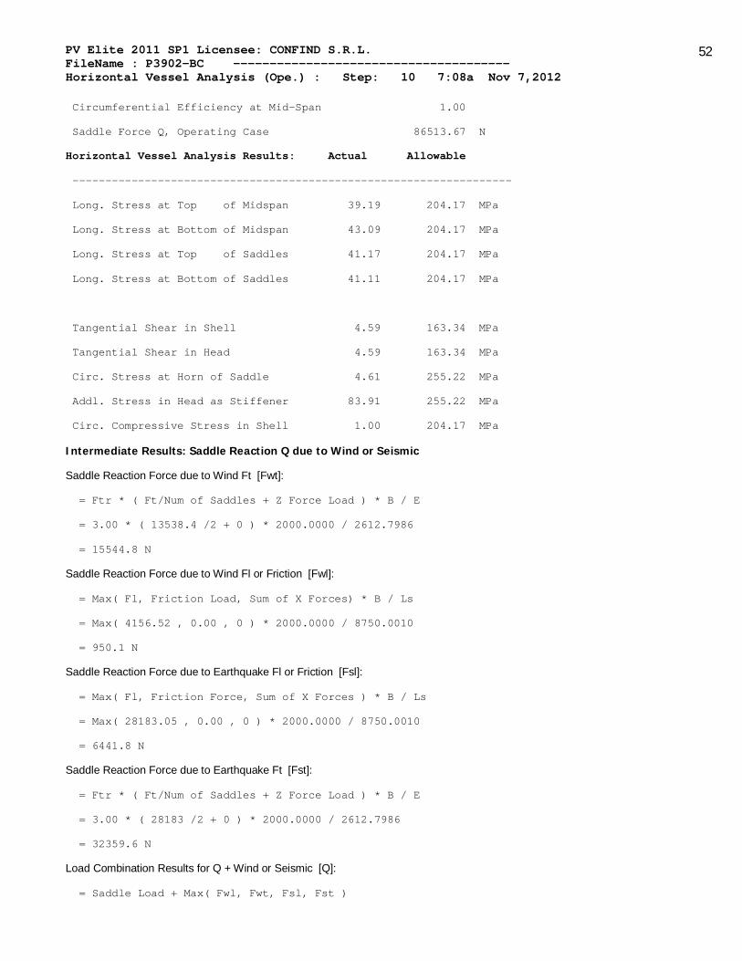
Circumferential Efficiency at Mid-Span 1.00
Saddle Force Q, Operating Case 86513.67 N
Horizontal Vessel Analysis Results: Actual Allowable
-------------------------------------------------------------------
Long. Stress at Top of Midspan 39.19 204.17 MPa
Long. Stress at Bottom of Midspan 43.09 204.17 MPa
Long. Stress at Top of Saddles 41.17 204.17 MPa
Long. Stress at Bottom of Saddles 41.11 204.17 MPa
Tangential Shear in Shell 4.59 163.34 MPa
Tangential Shear in Head 4.59 163.34 MPa
Circ. Stress at Horn of Saddle 4.61 255.22 MPa
Addl. Stress in Head as Stiffener 83.91 255.22 MPa
Circ. Compressive Stress in Shell 1.00 204.17 MPa
Intermediate Results: Saddle Reaction Q due to Wind or Seismic
Saddle Reaction Force due to Wind Ft [Fwt]:
= Ftr * ( Ft/Num of Saddles + Z Force Load ) * B / E
= 3.00 * ( 13538.4 /2 + 0 ) * 2000.0000 / 2612.7986
= 15544.8 N
Saddle Reaction Force due to Wind Fl or Friction [Fwl]:
= Max( Fl, Friction Load, Sum of X Forces) * B / Ls
= Max( 4156.52 , 0.00 , 0 ) * 2000.0000 / 8750.0010
= 950.1 N
Saddle Reaction Force due to Earthquake Fl or Friction [Fsl]:
= Max( Fl, Friction Force, Sum of X Forces ) * B / Ls
= Max( 28183.05 , 0.00 , 0 ) * 2000.0000 / 8750.0010
= 6441.8 N
Saddle Reaction Force due to Earthquake Ft [Fst]:
= Ftr * ( Ft/Num of Saddles + Z Force Load ) * B / E
= 3.00 * ( 28183 /2 + 0 ) * 2000.0000 / 2612.7986
= 32359.6 N
Load Combination Results for Q + Wind or Seismic [Q]:
= Saddle Load + Max( Fwl, Fwt, Fsl, Fst )

PV Elite 2011 SP1 Licensee: CONFIND S.R.L. FileName : P3902-BC -------------------------------------- Horizontal Vessel Analysis (Ope.) : Step: 10 7:08a Nov 7,2012
53
= 54154 + Max( 950 , 15544 , 6441 , 32359 )
= 86513.7 N
Summary of Loads at the base of this Saddle:
Vertical Load (including saddle weight) 94862.41 N
Transverse Shear Load Saddle 14091.53 N
Longitudinal Shear Load Saddle 28183.05 N
Formulas and Substitutions for Horizontal Vessel Analysis:
Note: Wear Plate is Welded to the Shell, k = 0.1
The Computed K values from Table 4.15.1:
K1 = 0.1066 K2 = 1.1707 K3 = 0.8799 K4 = 0.4011
K5 = 0.7603 K6 = 0.0529 K7 = 0.0132 K8 = 0.3405
K9 = 0.2711 K10 = 0.0581 K1* = 0.1923 K6p = 0.0472
K7P = 0.0118
The suffix 'p' denotes the values for a wear plate if it exists.
Note: Dimension a is less than Rm/2.
Moment per Equation 4.15.3 [M1]:
= -Q*a [1 - (1- a/L + (R²-h2²)/(2a*L))/(1+(4h2)/3L)]
= -86513*685.00[1-(1-685.00/10450.00+(1508.500²-753.000²)/
(2*685.00*10450.00))/(1+(4*753.00)/(3*10450.00))]
= -2287137.5 N-mm
Moment per Equation 4.15.4 [M2]:
= Q*L/4(1+2(R²-h2²)/(L²))/(1+(4h2)/( 3L))-4a/L
= 86513*10450/4(1+2(1508²-753²)/(10450²))/(1+(4*753)/
(3*10450))-4*684/10450
= 153458320.0 N-mm
Longitudinal Stress at Top of Shell (4.15.6) [Sigma1]:
= P * Rm/(2t) - M2/(pi*Rm²t)
= 0.60 * 1508.500 /(2*11.00 ) - .15346E+09/(pi*1508.5²*11.00 )
= 39.19 MPa
Longitudinal Stress at Bottom of Shell (4.15.7) [Sigma2]:
= P * Rm/(2t) + M2/(pi * Rm² * t)
= 0.60 * 1508.500 /(2 * 11.00 ) + .15346E+09/(pi * 1508.5² * 11.00 )
= 43.09 MPa

PV Elite 2011 SP1 Licensee: CONFIND S.R.L. FileName : P3902-BC -------------------------------------- Horizontal Vessel Analysis (Ope.) : Step: 10 7:08a Nov 7,2012
54
Longitudinal Stress at Top of Shell at Support (4.15.8) [Sigma3]:
= P * Rm/(2t) - M1/(pi * Rm² * t)
= 0.60 * 1508.500 /(2 * 11.00 ) - -2287137.5/(pi * 1508.5² * 11.00 )
= 41.17 MPa
Longitudinal Stress at bottom of Shell at Support (4.15.9) [Sigma4]:
= P * Rm/(2t) + M1/(pi*Rm²t)
= 0.60 * 1508.500 /(2*11.00 ) + -2287137.5/(pi*1508.5²*11.00 )
= 41.11 MPa
Maximum Shear Force in the Saddle (4.15.5) [T]:
= Q(L-2a)/(L+(4*h2/3))
= 86513 ( 10450.00 - 2 * 685.00 )/(10450.00 + ( 4 * 753.00 /3))
= 68582.5 N
Shear Stress in the shell no rings, stiffened (4.15.15) [tau3]:
= K3 * Q / ( Rm * t )
= 0.8799 * 86513 / ( 1508.5000 * 11.0000 )
= 4.59 MPa
Shear Stress in the head, shell stiffened (4.15.16) [tau3*]:
= K3 * Q / ( Rm * th )
= 0.8799 * 86513 / ( 1508.5000 * 11.0000 )
= 4.59 MPa
Membrane stress in the head as a stiffener (4.15.18) [sigma5]:
= K4 * Q/(Rm*th) + ((P*Ri)/(2*th)) * (Ri/h2)
= 0.4011 * 86513 /(1508.50 * 11.000 ) +
((0.60 * 1503.00 )/(2 * 11.000 ))*(1503.00 / 753.00 )
= 83.91 MPa
Decay Length (4.15.22) [x1,x2]:
= 0.78 * sqrt( Rm * t )
= 0.78 * sqrt( 1508.500 * 11.000 )
= 100.476 mm
Circumferential Stress in shell, no rings (4.15.23) [sigma6]:
= -K5 * Q * k / ( t * ( b + X1 + X2 ) )
= -0.7603 * 86513 * 0.1 / ( 11.000 * ( 400.00 + 100.48 + 100.48 ) )

PV Elite 2011 SP1 Licensee: CONFIND S.R.L. FileName : P3902-BC -------------------------------------- Horizontal Vessel Analysis (Ope.) : Step: 10 7:08a Nov 7,2012
55
= -1.00 MPa
Effective reinforcing plate width (4.15.1) [B1]:
= min( b + 1.56 * sqrt( Rm * t ), 2a )
= min( 400.00 + 1.56 * sqrt( 1508.500 * 11.000 ), 2 * 685.000 )
= 600.95 mm
Wear Plate/Shell Stress ratio (4.15.29) [eta]:
= min( Sr/S, 1 )
= min( 204.174 / 204.174 , 1 )
= 1.0000
Circumferential Stress at wear plate (4.15.26) [sigma6,r]:
= -K5 * Q * k / ( B1( t + eta * tr ) )
= -0.7603 * 86513 * 0.1 / ( 600.953 ( 11.000 + 1.000 * 14.000 ) )
= -0.44 MPa
Circ. Comp. Stress at Horn of Saddle, L<8Rm (4.15.28) [sigma7,r*]:
= -Q/(4(t+eta*tr)b1) - 12*K7*Q*Rm/(L(t+eta*tr)²)
= -86513 /(4(11.000 + 1.000 * 14.000 )600.953 ) -
12*0.013*86513*1508.500/(10450.00(11.000+1.000*14.000)²)
= -4.61 MPa
Results for Vessel Ribs, Web and Base
Baseplate Length Bplen 2400.0000 mm
Baseplate Thickness Bpthk 20.0000 mm
Baseplate Width Bpwid 400.0000 mm
Number of Ribs ( inc. outside ribs ) Nribs 4
Rib Thickness Ribtk 20.0000 mm
Web Thickness Webtk 20.0000 mm
Web Location Webloc Center
Moment of Inertia of Saddle - Lateral Direction
Y A AY Io
Shell 6. 7706. 42385. 310826.
Wearplate 18. 7000. 126000. 2382331.
Web 227. 8060. 1825590. 522580448.
BasePlate 438. 8000. 3504000. 1535017472.
Totals 688. 30766. 5497976. 2060291072.

PV Elite 2011 SP1 Licensee: CONFIND S.R.L. FileName : P3902-BC -------------------------------------- Horizontal Vessel Analysis (Ope.) : Step: 10 7:08a Nov 7,2012
56
Value C1 = Sumof(Ay)/Sumof(A) = 179. mm
Value I = Sumof(Io) - C1*Sumof(Ay) = 1077801472. mm**4
Value As = Sumof(A) - Ashell = 23060. mm²
K1 = (1+Cos(beta)-.5*Sin(beta)² )/(pi-beta+Sin(beta)*Cos(beta)) = 0.2035
Fh = K1 * Q = 0.2035 * 86513.672 = 17607.4102 N
Tension Stress, St = ( Fh/As ) = 0.7636 MPa
Allowed Stress, Sa = 0.6 * Yield Str = 143.9676 MPa
d = B - R*Sin(theta) / theta = 708.0291 mm
Bending Moment, M = Fh * d = 12471613.0000 N-mm
Bending Stress, Sb = ( M * C1 / I ) = 2.0671 MPa
Allowed Stress, Sa = 2/3 * Yield Str = 159.9640 MPa
Minimum Thickness of Baseplate per Moss :
= ( 3 * ( Q + Saddle_Wt ) * BasePlateWidth / ( 4 * BasePlateLength *
AllStress ))½
= ( 3 * (86513 + 8348 ) * 400.00 / ( 4 * 2400.000 * 159.964 ))½
= 8.610 mm
Calculation of Axial Load, Intermediate Values and Compressive Stress
Effective Baseplate Length [e]:
= ( Bplen - Clearance ) / ( Nribs - 1)
= ( 2400.0000 - 25.4 ) / ( 4 - 1 ) = 791.5333 mm
Baseplate Pressure Area [Ap]:
= e * Bpwid / 2
= 791.5333 * 400.0000 / 2 = 0.2E+06 mm²
Axial Load [P]:
= Ap * Bp
= 158306.7 * 0.09 = 14266.3 N
Area of the Rib and Web [Ar]:
= ( Bpwid - Clearance - Webtk ) * Ribtk + e/2 * Webtk
= ( 400.000 - 25.4 - 20.000 ) * 20.000 + 791.5333 /2 * 20.000
= 15007.332 mm²
Compressive Stress [Sc]:
= P/Ar
= 14266.3 / 15007.3320 = 0.9507 MPa

PV Elite 2011 SP1 Licensee: CONFIND S.R.L. FileName : P3902-BC -------------------------------------- Horizontal Vessel Analysis (Ope.) : Step: 10 7:08a Nov 7,2012
57
Check of Outside Ribs:
Inertia of Saddle, Outer Ribs - Longitudinal Direction
Y A AY Ay² Io
Rib 200.0 7346.0 1469200.0 0.0 96825736.0
Web 200.0 7915.3 1583066.5 0.0 527688.2
Values 200.0 15261.3 3052266.5 0.0 97353424.0
Bending Moment [Rm]:
= Fl /( 2 * Bplen ) * e * rl / 2
= 28183.1 /( 2 * 2400.00 ) * 791.533 * 1194.00 / 2
= 2775661 N-mm
KL/R < Cc ( 14.8245 < 128.2550 ) per AISC E2-1
Sca = (1-(Klr)²/(2*Cc²))*Fy/(5/3+3*(Klr)/(8*Cc)-(Klr³)/(8*Cc³)
Sca = ( 1-( 14.82 )²/(2 * 128.25² )) * 239 /
( 5/3+3*(14.82 )/(8* 128.25 )-( 14.82³)/(8*128.25³)
Sca = 139.40 MPa
AISC Unity Check on Outside Ribs ( must be <= 1.0 )
Check = Sc/Sca + (Rm/Z)/Sba
Check = 0.95 / 139.40 + (2775661 /486767.094) / 159.96
Check = 0.04
Check of Inside Ribs
Inertia of Saddle, Inner Ribs - Axial Direction
Y A AY Ay² Io
Rib 187.3 7092.0 1328331.4 0.0 87609584.0
Web 187.3 15830.7 2965083.8 0.0 527688.2
Values 187.3 22922.7 4293415.0 0.0 88137272.0
KL/R < Cc ( 7.6626 < 128.2550 ) per AISC E2-1
Sca = (1-(Klr)²/(2*Cc²))*Fy/(5/3+3*(Klr)/(8*Cc)-(Klr³)/(8*Cc³)
Sca = ( 1-( 7.66 )²/(2 * 128.25² )) * 239 /
( 5/3+3*(7.66 )/(8* 128.25 )-( 7.66³)/(8*128.25³)
Sca = 141.81 MPa
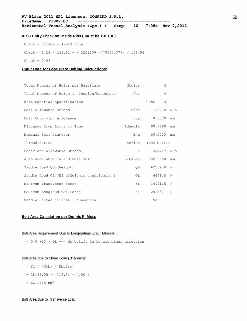
PV Elite 2011 SP1 Licensee: CONFIND S.R.L. FileName : P3902-BC -------------------------------------- Horizontal Vessel Analysis (Ope.) : Step: 10 7:08a Nov 7,2012
58
AISC Unity Check on Inside Ribs ( must be <= 1.0 )
Check = Sc/Sca + (Rm/Z)/Sba
Check = 1.24 / 141.81 + ( 2209106 /470567.375) / 159.96
Check = 0.04
Input Data for Base Plate Bolting Calculations:
Total Number of Bolts per BasePlate Nbolts 4
Total Number of Bolts in Tension/Baseplate Nbt 4
Bolt Material Specification C45E N
Bolt Allowable Stress Stba 113.34 MPa
Bolt Corrosion Allowance Bca 0.0000 mm
Distance from Bolts to Edge Edgedis 99.9998 mm
Nominal Bolt Diameter Bnd 30.0000 mm
Thread Series Series TEMA Metric
BasePlate Allowable Stress S 204.17 MPa
Area Available in a Single Bolt BltArea 502.9650 mm²
Saddle Load QO (Weight) QO 62502.8 N
Saddle Load QL (Wind/Seismic contribution) QL 6441.8 N
Maximum Transverse Force Ft 14091.5 N
Maximum Longitudinal Force Fl 28183.1 N
Saddle Bolted to Steel Foundation No
Bolt Area Calculation per Dennis R. Moss
Bolt Area Requirement Due to Longitudinal Load [Bltarearl]:
= 0.0 (QO > QL --> No Uplift in Longitudinal direction)
Bolt Area due to Shear Load [Bltarears]:
= Fl / (Stba * Nbolts)
= 28183.05 / (113.34 * 4.00 )
= 62.1718 mm²
Bolt Area due to Transverse Load

PV Elite 2011 SP1 Licensee: CONFIND S.R.L. FileName : P3902-BC -------------------------------------- Horizontal Vessel Analysis (Ope.) : Step: 10 7:08a Nov 7,2012
59
Moment on Baseplate Due to Transverse Load [Rmom]:
= B * Ft + Sum of X Moments
= 2000.00 * 14091.53 + 0.00
= 28194480.00 N-mm
Eccentricity (e):
= Rmom / QO
= 28194480 / 62502.80
= 450.91 mm > Bplen/6 --> Uplift in Transverse direction
f = Bplen / 2 - Edgedis
= 2400.00 / 2 - 100.00
= 1100.00 mm
Modular Ratio Of Steel/Concrete (n1):
= ES / EC
= 203402.50 / 21526.32
= 9.45
K1 = 3 (e - 0.5 * Bplen)
= 3 (450.91 - 0.5*2400.00 )
= -2247.27 mm
K2 = 6 * n1 * At / Bpwid * (f + e)
= 6 * 9.45 * 2011.86 / 400.00 * (1100.00 + 450.91 )
= 442243.87 mm ²
K3 = -K2 * (0.5 * Bplen + f)
= -442243.84 * (0.5 * 2400.00 + 1100.00 )
= -1017160927.88 mm ³
Iteratively Solving for the Effective Bearing Length:
Y³ + K1 * Y² + K2 * Y + K3 = 0
Y³ + -2247.27 * Y² + 442243.84 * Y + -0.1E+10 = 0
Y = 2251.50 mm
Num = (Bplen / 2 - Y / 3 - e)
= (2400.00 / 2 - 2251.50 / 3 - 450.91 )
= -1.41
Denom = (Bplen / 2 - Y / 3 + f)
= (2400.00 / 2 - 2251.50 / 3 + 1100.00 ) = 1549.50

PV Elite 2011 SP1 Licensee: CONFIND S.R.L. FileName : P3902-BC -------------------------------------- Horizontal Vessel Analysis (Ope.) : Step: 10 7:08a Nov 7,2012
60
Total Bolt Tension Force [Tforce]:
= - QO * Num / Denom
= - 62502.80 * -1.41 / 1549.50
= 56.89 N
Bolt Area Required due to Transverse Load [Bltareart]
= Tforce / (Stba * Nbt)
= 56.89 / ( 113.34 * 4.00 )
= 0.1255 mm²
Required of a Single Bolt [Bltarear]
= max[Bltarearl, Bltarears, Bltareart]
= max[0.0000 , 62.1718 , 0.1255 ]
= 62.1718 mm²
Baseplate Thickness Calculation per D. Moss:
Bearing Pressure (fc)
= 2 * (QO + Tforce) / (Y * Bplen)
= 2 * (62502.80 + 56.89 ) / (2251.50 * 2400.00 )
= 0.02 MPa
Distance from Baseplate Edge to the Web [ADIST]:
= (Bplen - Weblngth) / 2
= (2400.00 - 2349.20 ) / 2
= 25.4000 mm
Overturning Moment due To Bolt Tension [Mt]:
= Tforce * Adist
= 56.89 * 25.40
= 1445.50 N-mm
Equivalent Bearing Pressure (f1):
= fc * (Y - Adist) / Y
= 0.02 * (2251.50 - 25.40 ) / 2251.50
= 0.02 MPa
Overturning Moment due to Bearing Pressure [Mc]:
= (Adist² * Bpwid / 6) * (f1 + 2 * fc)
= (25.40² * 400.00 / 6) * (0.02 + 2 * 0.02 )
= 2977.68 N-mm
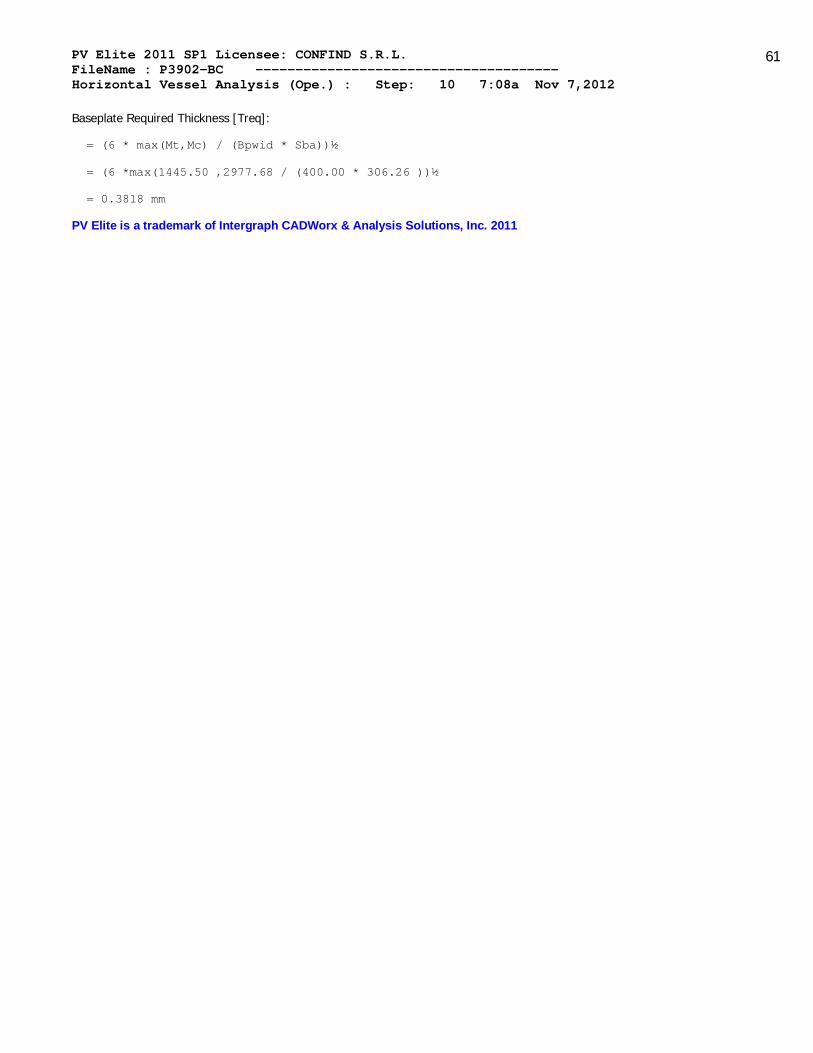
PV Elite 2011 SP1 Licensee: CONFIND S.R.L. FileName : P3902-BC -------------------------------------- Horizontal Vessel Analysis (Ope.) : Step: 10 7:08a Nov 7,2012
61
Baseplate Required Thickness [Treq]:
= (6 * max(Mt,Mc) / (Bpwid * Sba))½
= (6 *max(1445.50 ,2977.68 / (400.00 * 306.26 ))½
= 0.3818 mm
PV Elite is a trademark of Intergraph CADWorx & Analysis Solutions, Inc. 2011

PV Elite 2011 SP1 Licensee: CONFIND S.R.L. FileName : P3902-BC -------------------------------------- Horizontal Vessel Analysis (Test) : Step: 11 7:08a Nov 7,2012
62
ASME Horizontal Vessel Analysis: Stresses for the Left Saddle
(per ASME Sec. VIII Div. 2 based on the Zick method.)
Horizontal Vessel Stress Calculations : Test Case
Input and Calculated Values:
Vessel Mean Radius Rm 1507.00 mm
Stiffened Vessel Length per 4.15.6 L 10450.00 mm
Distance from Saddle to Vessel tangent a 685.00 mm
Saddle Width b 400.00 mm
Saddle Bearing Angle theta 120.00
Wear Plate Width b1 500.00 mm
Wear Plate Bearing Angle theta1 127.00
Wear Plate Thickness tr 14.0 mm
Wear Plate Allowable Stress Sr 204.17 MPa
Inside Depth of Head h2 750.00 mm
Shell Allowable Stress used in Calculation 204.17 MPa
Head Allowable Stress used in Calculation 204.17 MPa
Circumferential Efficiency in Plane of Saddle 1.00
Circumferential Efficiency at Mid-Span 1.00
Saddle Force Q, Test Case, no Ext. Forces 474750.47 N
Horizontal Vessel Analysis Results: Actual Allowable
-------------------------------------------------------------------
Long. Stress at Top of Midspan 73.33 204.17 MPa
Long. Stress at Bottom of Midspan 90.19 204.17 MPa
Long. Stress at Top of Saddles 81.89 204.17 MPa
Long. Stress at Bottom of Saddles 81.64 204.17 MPa
Tangential Shear in Shell 19.80 163.34 MPa
Tangential Shear in Head 19.80 163.34 MPa
Circ. Stress at Horn of Saddle 20.61 255.22 MPa
Addl. Stress in Head as Stiffener 171.79 255.22 MPa
Circ. Compressive Stress in Shell 4.11 204.17 MPa
Intermediate Results: Saddle Reaction Q due to Wind or Seismic

PV Elite 2011 SP1 Licensee: CONFIND S.R.L. FileName : P3902-BC -------------------------------------- Horizontal Vessel Analysis (Test) : Step: 11 7:08a Nov 7,2012
63
Saddle Reaction Force due to Wind Ft [Fwt]:
= Ftr * ( Ft/Num of Saddles + Z Force Load ) * B / E
= 3.00 * ( 4467.7 /2 + 0 ) * 2000.0000 / 2610.2007
= 5134.9 N
Saddle Reaction Force due to Wind Fl or Friction [Fwl]:
= Max( Fl, Friction Load, Sum of X Forces) * B / Ls
= Max( 4156.52 , 0.00 , 0 ) * 2000.0000 / 8750.0010
= 313.5 N
Load Combination Results for Q + Wind or Seismic [Q]:
= Saddle Load + Max( Fwl, Fwt, Fsl, Fst )
= 469615 + Max( 313 , 5134 , 0 , 0 )
= 474750.5 N
Summary of Loads at the base of this Saddle:
Vertical Load (including saddle weight) 483099.19 N
Transverse Shear Load Saddle 2233.84 N
Longitudinal Shear Load Saddle 1371.65 N
Hydrostatic Test Pressure at center of Vessel: 1.519 MPa
Formulas and Substitutions for Horizontal Vessel Analysis:
Note: Wear Plate is Welded to the Shell, k = 0.1
The Computed K values from Table 4.15.1:
K1 = 0.1066 K2 = 1.1707 K3 = 0.8799 K4 = 0.4011
K5 = 0.7603 K6 = 0.0529 K7 = 0.0132 K8 = 0.3405
K9 = 0.2711 K10 = 0.0581 K1* = 0.1923 K6p = 0.0472
K7P = 0.0118
The suffix 'p' denotes the values for a wear plate if it exists.
Note: Dimension a is less than Rm/2.
Moment per Equation 4.15.3 [M1]:
= -Q*a [1 - (1- a/L + (R²-h2²)/(2a*L))/(1+(4h2)/3L)]
= -474750*685.00[1-(1-685.00/10450.00+(1507.000²-750.000²)/
(2*685.00*10450.00))/(1+(4*750.00)/(3*10450.00))]
= -12441862.0 N-mm
Moment per Equation 4.15.4 [M2]:
= Q*L/4(1+2(R²-h2²)/(L²))/(1+(4h2)/( 3L))-4a/L

PV Elite 2011 SP1 Licensee: CONFIND S.R.L. FileName : P3902-BC -------------------------------------- Horizontal Vessel Analysis (Test) : Step: 11 7:08a Nov 7,2012
64
= 474750*10450/4(1+2(1507²-750²)/(10450²))/(1+(4*750)/
(3*10450))-4*684/10450
= 842521984.0 N-mm
Longitudinal Stress at Top of Shell (4.15.6) [Sigma1]:
= P * Rm/(2t) - M2/(pi*Rm²t)
= 1.52 * 1507.000 /(2*14.00 ) - .84252E+09/(pi*1507.0²*14.00 )
= 73.33 MPa
Longitudinal Stress at Bottom of Shell (4.15.7) [Sigma2]:
= P * Rm/(2t) + M2/(pi * Rm² * t)
= 1.52 * 1507.000 /(2 * 14.00 ) + .84252E+09/(pi * 1507.0² * 14.00 )
= 90.19 MPa
Longitudinal Stress at Top of Shell at Support (4.15.8) [Sigma3]:
= P * Rm/(2t) - M1/(pi * Rm² * t)
= 1.52 * 1507.000 /(2 * 14.00 ) - -0.1E+08/(pi * 1507.0² * 14.00 )
= 81.89 MPa
Longitudinal Stress at bottom of Shell at Support (4.15.9) [Sigma4]:
= P * Rm/(2t) + M1/(pi*Rm²t)
= 1.52 * 1507.000 /(2*14.00 ) + -0.1E+08/(pi*1507.0²*14.00 )
= 81.64 MPa
Maximum Shear Force in the Saddle (4.15.5) [T]:
= Q(L-2a)/(L+(4*h2/3))
= 474750 ( 10450.00 - 2 * 685.00 )/(10450.00 + ( 4 * 750.00 /3))
= 376483.3 N
Shear Stress in the shell no rings, stiffened (4.15.15) [tau3]:
= K3 * Q / ( Rm * t )
= 0.8799 * 474750 / ( 1507.0000 * 14.0000 )
= 19.80 MPa
Shear Stress in the head, shell stiffened (4.15.16) [tau3*]:
= K3 * Q / ( Rm * th )
= 0.8799 * 474750 / ( 1507.0000 * 14.0000 )
= 19.80 MPa
Membrane stress in the head as a stiffener (4.15.18) [sigma5]:
= K4 * Q/(Rm*th) + ((P*Ri)/(2*th)) * (Ri/h2)

PV Elite 2011 SP1 Licensee: CONFIND S.R.L. FileName : P3902-BC -------------------------------------- Horizontal Vessel Analysis (Test) : Step: 11 7:08a Nov 7,2012
65
= 0.4011 * 474750 /(1507.00 * 14.000 ) +
((1.52 * 1500.00 )/(2 * 14.000 ))*(1500.00 / 750.00 )
= 171.79 MPa
Decay Length (4.15.22) [x1,x2]:
= 0.78 * sqrt( Rm * t )
= 0.78 * sqrt( 1507.000 * 14.000 )
= 113.296 mm
Circumferential Stress in shell, no rings (4.15.23) [sigma6]:
= -K5 * Q * k / ( t * ( b + X1 + X2 ) )
= -0.7603 * 474750 * 0.1 / ( 14.000 * ( 400.00 + 113.30 + 113.30 ) )
= -4.11 MPa
Effective reinforcing plate width (4.15.1) [B1]:
= min( b + 1.56 * sqrt( Rm * t ), 2a )
= min( 400.00 + 1.56 * sqrt( 1507.000 * 14.000 ), 2 * 685.000 )
= 626.59 mm
Wear Plate/Shell Stress ratio (4.15.29) [eta]:
= min( Sr/S, 1 )
= min( 204.174 / 204.174 , 1 )
= 1.0000
Circumferential Stress at wear plate (4.15.26) [sigma6,r]:
= -K5 * Q * k / ( B1( t + eta * tr ) )
= -0.7603 * 474750 * 0.1 / ( 626.592 ( 14.000 + 1.000 * 14.000 ) )
= -2.06 MPa
Circ. Comp. Stress at Horn of Saddle, L<8Rm (4.15.28) [sigma7,r*]:
= -Q/(4(t+eta*tr)b1) - 12*K7*Q*Rm/(L(t+eta*tr)²)
= -474750 /(4(14.000 + 1.000 * 14.000 )626.592 ) -
12*0.013*474750*1507.000/(10450.00(14.000+1.000*14.000)²)
= -20.61 MPa
Results for Vessel Ribs, Web and Base:
Baseplate Length Bplen 2400.0000 mm
Baseplate Thickness Bpthk 20.0000 mm
Baseplate Width Bpwid 400.0000 mm

PV Elite 2011 SP1 Licensee: CONFIND S.R.L. FileName : P3902-BC -------------------------------------- Horizontal Vessel Analysis (Test) : Step: 11 7:08a Nov 7,2012
66
Number of Ribs ( inc. outside ribs ) Nribs 4
Rib Thickness Ribtk 20.0000 mm
Web Thickness Webtk 20.0000 mm
Web Location Webloc Center
Moment of Inertia of Saddle - Lateral Direction
Y A AY Io
Shell 7. 10165. 71154. 664107.
Wearplate 21. 7000. 147000. 3201331.
Web 228. 8000. 1824000. 522538176.
BasePlate 438. 8000. 3504000. 1535017088.
Totals 694. 33165. 5546154. 2061420672.
Value C1 = Sumof(Ay)/Sumof(A) = 167. mm
Value I = Sumof(Io) - C1*Sumof(Ay) = 1133940736. mm**4
Value As = Sumof(A) - Ashell = 23000. mm²
K1 = (1+Cos(beta)-.5*Sin(beta)² )/(pi-beta+Sin(beta)*Cos(beta)) = 0.2035
Fh = K1 * Q = 0.2035 * 474750.469 = 96622.0234 N
Tension Stress, St = ( Fh/As ) = 4.2013 MPa
Allowed Stress, Sa = 0.6 * Yield Str = 143.9676 MPa
d = B - R*Sin(theta) / theta = 707.5100 mm
Bending Moment, M = Fh * d = 68388768.0000 N-mm
Bending Stress, Sb = ( M * C1 / I ) = 10.0825 MPa
Allowed Stress, Sa = 2/3 * Yield Str = 159.9640 MPa
Minimum Thickness of Baseplate per Moss :
= ( 3 * ( Q + Saddle_Wt ) * BasePlateWidth / ( 4 * BasePlateLength *
AllStress ))½
= ( 3 * (474750 + 8348 ) * 400.00 / ( 4 * 2400.000 * 159.964 ))½
= 19.430 mm
Calculation of Axial Load, Intermediate Values and Compressive Stress
Effective Baseplate Length [e]:
= ( Bplen - Clearance ) / ( Nribs - 1)
= ( 2400.0000 - 25.4 ) / ( 4 - 1 ) = 791.5333 mm

PV Elite 2011 SP1 Licensee: CONFIND S.R.L. FileName : P3902-BC -------------------------------------- Horizontal Vessel Analysis (Test) : Step: 11 7:08a Nov 7,2012
67
Baseplate Pressure Area [Ap]:
= e * Bpwid / 2
= 791.5333 * 400.0000 / 2 = 0.2E+06 mm²
Axial Load [P]:
= Ap * Bp
= 158306.7 * 0.49 = 78287.7 N
Area of the Rib and Web [Ar]:
= ( Bpwid - Clearance - Webtk ) * Ribtk + e/2 * Webtk
= ( 400.000 - 25.4 - 20.000 ) * 20.000 + 791.5333 /2 * 20.000
= 15007.332 mm²
Compressive Stress [Sc]:
= P/Ar
= 78287.7 / 15007.3320 = 5.2171 MPa
Check of Outside Ribs:
Inertia of Saddle, Outer Ribs - Longitudinal Direction
Y A AY Ay² Io
Rib 200.0 7346.0 1469200.0 0.0 96825736.0
Web 200.0 7915.3 1583066.5 0.0 527688.2
Values 200.0 15261.3 3052266.5 0.0 97353424.0
Bending Moment [Rm]:
= Fl /( 2 * Bplen ) * e * rl / 2
= 1371.7 /( 2 * 2400.00 ) * 791.533 * 1191.00 / 2
= 134750.391 N-mm
KL/R < Cc ( 14.7873 < 128.2550 ) per AISC E2-1
Sca = (1-(Klr)²/(2*Cc²))*Fy/(5/3+3*(Klr)/(8*Cc)-(Klr³)/(8*Cc³)
Sca = ( 1-( 14.79 )²/(2 * 128.25² )) * 239 /
( 5/3+3*(14.79 )/(8* 128.25 )-( 14.79³)/(8*128.25³)
Sca = 139.41 MPa
AISC Unity Check on Outside Ribs ( must be <= 1.0 )
Check = Sc/Sca + (Rm/Z)/Sba
Check = 5.22 / 139.41 + (134750.39 /486767.094) / 159.96
Check = 0.04

PV Elite 2011 SP1 Licensee: CONFIND S.R.L. FileName : P3902-BC -------------------------------------- Horizontal Vessel Analysis (Test) : Step: 11 7:08a Nov 7,2012
68
Check of Inside Ribs
Inertia of Saddle, Inner Ribs - Axial Direction
Y A AY Ay² Io
Rib 187.3 7092.0 1328331.4 0.0 87609584.0
Web 187.3 15830.7 2965083.8 0.0 527688.2
Values 187.3 22922.7 4293415.0 0.0 88137272.0
KL/R < Cc ( 7.6142 < 128.2550 ) per AISC E2-1
Sca = (1-(Klr)²/(2*Cc²))*Fy/(5/3+3*(Klr)/(8*Cc)-(Klr³)/(8*Cc³)
Sca = ( 1-( 7.61 )²/(2 * 128.25² )) * 239 /
( 5/3+3*(7.61 )/(8* 128.25 )-( 7.61³)/(8*128.25³)
Sca = 141.82 MPa
AISC Unity Check on Inside Ribs ( must be <= 1.0 )
Check = Sc/Sca + (Rm/Z)/Sba
Check = 6.83 / 141.82 + ( 106837.11 /470567.375) / 159.96
Check = 0.05
Input Data for Base Plate Bolting Calculations:
Total Number of Bolts per BasePlate Nbolts 4
Total Number of Bolts in Tension/Baseplate Nbt 4
Bolt Material Specification C45E N
Bolt Allowable Stress Stba 113.34 MPa
Bolt Corrosion Allowance Bca 0.0000 mm
Distance from Bolts to Edge Edgedis 99.9998 mm
Nominal Bolt Diameter Bnd 30.0000 mm
Thread Series Series TEMA Metric
BasePlate Allowable Stress S 204.17 MPa
Area Available in a Single Bolt BltArea 502.9650 mm²
Saddle Load QO (Weight) QO 477964.3 N
Saddle Load QL (Wind/Seismic contribution) QL 313.5 N
Maximum Transverse Force Ft 2233.8 N
Maximum Longitudinal Force Fl 1371.7 N
Saddle Bolted to Steel Foundation No

PV Elite 2011 SP1 Licensee: CONFIND S.R.L. FileName : P3902-BC -------------------------------------- Horizontal Vessel Analysis (Test) : Step: 11 7:08a Nov 7,2012
69
Bolt Area Calculation per Dennis R. Moss
Bolt Area Requirement Due to Longitudinal Load [Bltarearl]:
= 0.0 (QO > QL --> No Uplift in Longitudinal direction)
Bolt Area due to Shear Load [Bltarears]:
= Fl / (Stba * Nbolts)
= 1371.65 / (113.34 * 4.00 )
= 3.0259 mm²
Bolt Area due to Transverse Load
Moment on Baseplate Due to Transverse Load [Rmom]:
= B * Ft + Sum of X Moments
= 2000.00 * 2233.84 + 0.00
= 4469496.00 N-mm
Eccentricity (e):
= Rmom / QO
= 4469496 / 477964.31
= 9.35 mm < Bplen/6 --> No Uplift in Transverse direction
Bolt Area due to Transverse Load [Bltareart]:
= 0 (No Uplift)
Required of a Single Bolt [Bltarear]
= max[Bltarearl, Bltarears, Bltareart]
= max[0.0000 , 3.0259 , 0.0000 ]
= 3.0259 mm²
ASME Horizontal Vessel Analysis: Stresses for the Right Saddle
(per ASME Sec. VIII Div. 2 based on the Zick method.)
Input and Calculated Values:
Vessel Mean Radius Rm 1507.00 mm
Stiffened Vessel Length per 4.15.6 L 10450.00 mm
Distance from Saddle to Vessel tangent a 685.00 mm
Saddle Width b 400.00 mm
Saddle Bearing Angle theta 120.00
Wear Plate Width b1 500.00 mm
Wear Plate Bearing Angle theta1 127.00
Wear Plate Thickness tr 14.0 mm

PV Elite 2011 SP1 Licensee: CONFIND S.R.L. FileName : P3902-BC -------------------------------------- Horizontal Vessel Analysis (Test) : Step: 11 7:08a Nov 7,2012
70
Wear Plate Allowable Stress Sr 204.17 MPa
Inside Depth of Head h2 750.00 mm
Shell Allowable Stress used in Calculation 204.17 MPa
Head Allowable Stress used in Calculation 204.17 MPa
Circumferential Efficiency in Plane of Saddle 1.00
Circumferential Efficiency at Mid-Span 1.00
Saddle Force Q, Test Case, no Ext. Forces 465130.22 N
Horizontal Vessel Analysis Results: Actual Allowable
-------------------------------------------------------------------
Long. Stress at Top of Midspan 73.50 204.17 MPa
Long. Stress at Bottom of Midspan 90.02 204.17 MPa
Long. Stress at Top of Saddles 81.88 204.17 MPa
Long. Stress at Bottom of Saddles 81.64 204.17 MPa
Tangential Shear in Shell 19.40 163.34 MPa
Tangential Shear in Head 19.40 163.34 MPa
Circ. Stress at Horn of Saddle 20.20 255.22 MPa
Addl. Stress in Head as Stiffener 171.61 255.22 MPa
Circ. Compressive Stress in Shell 4.03 204.17 MPa
Intermediate Results: Saddle Reaction Q due to Wind or Seismic
Saddle Reaction Force due to Wind Ft [Fwt]:
= Ftr * ( Ft/Num of Saddles + Z Force Load ) * B / E
= 3.00 * ( 4467.7 /2 + 0 ) * 2000.0000 / 2610.2007
= 5134.9 N
Saddle Reaction Force due to Wind Fl or Friction [Fwl]:
= Max( Fl, Friction Load, Sum of X Forces) * B / Ls
= Max( 4156.52 , 0.00 , 0 ) * 2000.0000 / 8750.0010
= 313.5 N
Load Combination Results for Q + Wind or Seismic [Q]:
= Saddle Load + Max( Fwl, Fwt, Fsl, Fst )
= 459995 + Max( 313 , 5134 , 0 , 0 )
= 465130.2 N

PV Elite 2011 SP1 Licensee: CONFIND S.R.L. FileName : P3902-BC -------------------------------------- Horizontal Vessel Analysis (Test) : Step: 11 7:08a Nov 7,2012
71
Summary of Loads at the base of this Saddle:
Vertical Load (including saddle weight) 473478.94 N
Transverse Shear Load Saddle 2233.84 N
Longitudinal Shear Load Saddle 1371.65 N
Hydrostatic Test Pressure at center of Vessel: 1.519 MPa
Formulas and Substitutions for Horizontal Vessel Analysis:
Note: Wear Plate is Welded to the Shell, k = 0.1
The Computed K values from Table 4.15.1:
K1 = 0.1066 K2 = 1.1707 K3 = 0.8799 K4 = 0.4011
K5 = 0.7603 K6 = 0.0529 K7 = 0.0132 K8 = 0.3405
K9 = 0.2711 K10 = 0.0581 K1* = 0.1923 K6p = 0.0472
K7P = 0.0118
The suffix 'p' denotes the values for a wear plate if it exists.
Note: Dimension a is less than Rm/2.
Moment per Equation 4.15.3 [M1]:
= -Q*a [1 - (1- a/L + (R²-h2²)/(2a*L))/(1+(4h2)/3L)]
= -465130*685.00[1-(1-685.00/10450.00+(1507.000²-750.000²)/
(2*685.00*10450.00))/(1+(4*750.00)/(3*10450.00))]
= -12189741.0 N-mm
Moment per Equation 4.15.4 [M2]:
= Q*L/4(1+2(R²-h2²)/(L²))/(1+(4h2)/( 3L))-4a/L
= 465130*10450/4(1+2(1507²-750²)/(10450²))/(1+(4*750)/
(3*10450))-4*684/10450
= 825449280.0 N-mm
Longitudinal Stress at Top of Shell (4.15.6) [Sigma1]:
= P * Rm/(2t) - M2/(pi*Rm²t)
= 1.52 * 1507.000 /(2*14.00 ) - .82545E+09/(pi*1507.0²*14.00 )
= 73.50 MPa
Longitudinal Stress at Bottom of Shell (4.15.7) [Sigma2]:
= P * Rm/(2t) + M2/(pi * Rm² * t)
= 1.52 * 1507.000 /(2 * 14.00 ) + .82545E+09/(pi * 1507.0² * 14.00 )
= 90.02 MPa

PV Elite 2011 SP1 Licensee: CONFIND S.R.L. FileName : P3902-BC -------------------------------------- Horizontal Vessel Analysis (Test) : Step: 11 7:08a Nov 7,2012
72
Longitudinal Stress at Top of Shell at Support (4.15.8) [Sigma3]:
= P * Rm/(2t) - M1/(pi * Rm² * t)
= 1.52 * 1507.000 /(2 * 14.00 ) - -0.1E+08/(pi * 1507.0² * 14.00 )
= 81.88 MPa
Longitudinal Stress at bottom of Shell at Support (4.15.9) [Sigma4]:
= P * Rm/(2t) + M1/(pi*Rm²t)
= 1.52 * 1507.000 /(2*14.00 ) + -0.1E+08/(pi*1507.0²*14.00 )
= 81.64 MPa
Maximum Shear Force in the Saddle (4.15.5) [T]:
= Q(L-2a)/(L+(4*h2/3))
= 465130 ( 10450.00 - 2 * 685.00 )/(10450.00 + ( 4 * 750.00 /3))
= 368854.3 N
Shear Stress in the shell no rings, stiffened (4.15.15) [tau3]:
= K3 * Q / ( Rm * t )
= 0.8799 * 465130 / ( 1507.0000 * 14.0000 )
= 19.40 MPa
Shear Stress in the head, shell stiffened (4.15.16) [tau3*]:
= K3 * Q / ( Rm * th )
= 0.8799 * 465130 / ( 1507.0000 * 14.0000 )
= 19.40 MPa
Membrane stress in the head as a stiffener (4.15.18) [sigma5]:
= K4 * Q/(Rm*th) + ((P*Ri)/(2*th)) * (Ri/h2)
= 0.4011 * 465130 /(1507.00 * 14.000 ) +
((1.52 * 1500.00 )/(2 * 14.000 ))*(1500.00 / 750.00 )
= 171.61 MPa
Decay Length (4.15.22) [x1,x2]:
= 0.78 * sqrt( Rm * t )
= 0.78 * sqrt( 1507.000 * 14.000 )
= 113.296 mm
Circumferential Stress in shell, no rings (4.15.23) [sigma6]:
= -K5 * Q * k / ( t * ( b + X1 + X2 ) )
= -0.7603 * 465130 * 0.1 / ( 14.000 * ( 400.00 + 113.30 + 113.30 ) )
= -4.03 MPa

PV Elite 2011 SP1 Licensee: CONFIND S.R.L. FileName : P3902-BC -------------------------------------- Horizontal Vessel Analysis (Test) : Step: 11 7:08a Nov 7,2012
73
Effective reinforcing plate width (4.15.1) [B1]:
= min( b + 1.56 * sqrt( Rm * t ), 2a )
= min( 400.00 + 1.56 * sqrt( 1507.000 * 14.000 ), 2 * 685.000 )
= 626.59 mm
Wear Plate/Shell Stress ratio (4.15.29) [eta]:
= min( Sr/S, 1 )
= min( 204.174 / 204.174 , 1 )
= 1.0000
Circumferential Stress at wear plate (4.15.26) [sigma6,r]:
= -K5 * Q * k / ( B1( t + eta * tr ) )
= -0.7603 * 465130 * 0.1 / ( 626.592 ( 14.000 + 1.000 * 14.000 ) )
= -2.02 MPa
Circ. Comp. Stress at Horn of Saddle, L<8Rm (4.15.28) [sigma7,r*]:
= -Q/(4(t+eta*tr)b1) - 12*K7*Q*Rm/(L(t+eta*tr)²)
= -465130 /(4(14.000 + 1.000 * 14.000 )626.592 ) -
12*0.013*465130*1507.000/(10450.00(14.000+1.000*14.000)²)
= -20.20 MPa
Results for Vessel Ribs, Web and Base
Baseplate Length Bplen 2400.0000 mm
Baseplate Thickness Bpthk 20.0000 mm
Baseplate Width Bpwid 400.0000 mm
Number of Ribs ( inc. outside ribs ) Nribs 4
Rib Thickness Ribtk 20.0000 mm
Web Thickness Webtk 20.0000 mm
Web Location Webloc Center
Moment of Inertia of Saddle - Lateral Direction
Y A AY Io
Shell 7. 10165. 71154. 664107.
Wearplate 21. 7000. 147000. 3201331.
Web 228. 8000. 1824000. 522538176.
BasePlate 438. 8000. 3504000. 1535017088.
Totals 694. 33165. 5546154. 2061420672.

PV Elite 2011 SP1 Licensee: CONFIND S.R.L. FileName : P3902-BC -------------------------------------- Horizontal Vessel Analysis (Test) : Step: 11 7:08a Nov 7,2012
74
Value C1 = Sumof(Ay)/Sumof(A) = 167. mm
Value I = Sumof(Io) - C1*Sumof(Ay) = 1133940736. mm**4
Value As = Sumof(A) - Ashell = 23000. mm²
K1 = (1+Cos(beta)-.5*Sin(beta)² )/(pi-beta+Sin(beta)*Cos(beta)) = 0.2035
Fh = K1 * Q = 0.2035 * 465130.219 = 94664.1016 N
Tension Stress, St = ( Fh/As ) = 4.1162 MPa
Allowed Stress, Sa = 0.6 * Yield Str = 143.9676 MPa
d = B - R*Sin(theta) / theta = 707.5100 mm
Bending Moment, M = Fh * d = 67002952.0000 N-mm
Bending Stress, Sb = ( M * C1 / I ) = 9.8782 MPa
Allowed Stress, Sa = 2/3 * Yield Str = 159.9640 MPa
Minimum Thickness of Baseplate per Moss :
= ( 3 * ( Q + Saddle_Wt ) * BasePlateWidth / ( 4 * BasePlateLength *
AllStress ))½
= ( 3 * (465130 + 8348 ) * 400.00 / ( 4 * 2400.000 * 159.964 ))½
= 19.236 mm
Calculation of Axial Load, Intermediate Values and Compressive Stress
Effective Baseplate Length [e]:
= ( Bplen - Clearance ) / ( Nribs - 1)
= ( 2400.0000 - 25.4 ) / ( 4 - 1 ) = 791.5333 mm
Baseplate Pressure Area [Ap]:
= e * Bpwid / 2
= 791.5333 * 400.0000 / 2 = 0.2E+06 mm²
Axial Load [P]:
= Ap * Bp
= 158306.7 * 0.48 = 76701.3 N
Area of the Rib and Web [Ar]:
= ( Bpwid - Clearance - Webtk ) * Ribtk + e/2 * Webtk
= ( 400.000 - 25.4 - 20.000 ) * 20.000 + 791.5333 /2 * 20.000
= 15007.332 mm²
Compressive Stress [Sc]:
= P/Ar = 76701.3 / 15007.3320 = 5.1114 MPa

PV Elite 2011 SP1 Licensee: CONFIND S.R.L. FileName : P3902-BC -------------------------------------- Horizontal Vessel Analysis (Test) : Step: 11 7:08a Nov 7,2012
75
Check of Outside Ribs:
Inertia of Saddle, Outer Ribs - Longitudinal Direction
Y A AY Ay² Io
Rib 200.0 7346.0 1469200.0 0.0 96825736.0
Web 200.0 7915.3 1583066.5 0.0 527688.2
Values 200.0 15261.3 3052266.5 0.0 97353424.0
Bending Moment [Rm]:
= Fl /( 2 * Bplen ) * e * rl / 2
= 1371.7 /( 2 * 2400.00 ) * 791.533 * 1191.00 / 2
= 134750.391 N-mm
KL/R < Cc ( 14.7873 < 128.2550 ) per AISC E2-1
Sca = (1-(Klr)²/(2*Cc²))*Fy/(5/3+3*(Klr)/(8*Cc)-(Klr³)/(8*Cc³)
Sca = ( 1-( 14.79 )²/(2 * 128.25² )) * 239 /
( 5/3+3*(14.79 )/(8* 128.25 )-( 14.79³)/(8*128.25³)
Sca = 139.41 MPa
AISC Unity Check on Outside Ribs ( must be <= 1.0 )
Check = Sc/Sca + (Rm/Z)/Sba
Check = 5.11 / 139.41 + (134750.39 /486767.094) / 159.96
Check = 0.04
Check of Inside Ribs
Inertia of Saddle, Inner Ribs - Axial Direction
Y A AY Ay² Io
Rib 187.3 7092.0 1328331.4 0.0 87609584.0
Web 187.3 15830.7 2965083.8 0.0 527688.2
Values 187.3 22922.7 4293415.0 0.0 88137272.0
KL/R < Cc ( 7.6142 < 128.2550 ) per AISC E2-1
Sca = (1-(Klr)²/(2*Cc²))*Fy/(5/3+3*(Klr)/(8*Cc)-(Klr³)/(8*Cc³)
Sca = ( 1-( 7.61 )²/(2 * 128.25² )) * 239 /
( 5/3+3*(7.61 )/(8* 128.25 )-( 7.61³)/(8*128.25³)
Sca = 141.82 MPa

PV Elite 2011 SP1 Licensee: CONFIND S.R.L. FileName : P3902-BC -------------------------------------- Horizontal Vessel Analysis (Test) : Step: 11 7:08a Nov 7,2012
76
AISC Unity Check on Inside Ribs ( must be <= 1.0 )
Check = Sc/Sca + (Rm/Z)/Sba
Check = 6.69 / 141.82 + ( 106837.11 /470567.375) / 159.96
Check = 0.05
Input Data for Base Plate Bolting Calculations:
Total Number of Bolts per BasePlate Nbolts 4
Total Number of Bolts in Tension/Baseplate Nbt 4
Bolt Material Specification C45E N
Bolt Allowable Stress Stba 113.34 MPa
Bolt Corrosion Allowance Bca 0.0000 mm
Distance from Bolts to Edge Edgedis 99.9998 mm
Nominal Bolt Diameter Bnd 30.0000 mm
Thread Series Series TEMA Metric
BasePlate Allowable Stress S 204.17 MPa
Area Available in a Single Bolt BltArea 502.9650 mm²
Saddle Load QO (Weight) QO 468344.1 N
Saddle Load QL (Wind/Seismic contribution) QL 313.5 N
Maximum Transverse Force Ft 2233.8 N
Maximum Longitudinal Force Fl 1371.7 N
Saddle Bolted to Steel Foundation No
Bolt Area Calculation per Dennis R. Moss
Bolt Area Requirement Due to Longitudinal Load [Bltarearl]:
= 0.0 (QO > QL --> No Uplift in Longitudinal direction)
Bolt Area due to Shear Load [Bltarears]:
= Fl / (Stba * Nbolts)
= 1371.65 / (113.34 * 4.00 )
= 3.0259 mm²
Bolt Area due to Transverse Load
Moment on Baseplate Due to Transverse Load [Rmom]:
= B * Ft + Sum of X Moments
= 2000.00 * 2233.84 + 0.00
= 4469496.00 N-mm

PV Elite 2011 SP1 Licensee: CONFIND S.R.L. FileName : P3902-BC -------------------------------------- Horizontal Vessel Analysis (Test) : Step: 11 7:08a Nov 7,2012
77
Eccentricity (e):
= Rmom / QO
= 4469496 / 468344.06
= 9.54 mm < Bplen/6 --> No Uplift in Transverse direction
Bolt Area due to Transverse Load [Bltareart]:
= 0 (No Uplift)
Required of a Single Bolt [Bltarear]
= max[Bltarearl, Bltarears, Bltareart]
= max[0.0000 , 3.0259 , 0.0000 ]
= 3.0259 mm²
PV Elite is a trademark of Intergraph CADWorx & Analysis Solutions, Inc. 2011

PV Elite 2011 SP1 Licensee: CONFIND S.R.L. FileName : P3902-BC -------------------------------------- Nozzle Calcs. : GV1a Nozl: 1 7:08a Nov 7,2012
78
INPUT VALUES, Nozzle Description: GV1a From : 10
Pressure for Reinforcement Calculations P 0.6000 MPa
Temperature for Internal Pressure Temp 60 C
Shell Material P355NH
Shell Allowable Stress at Temperature S 204.17 MPa
Shell Allowable Stress At Ambient Sa 204.17 MPa
Inside Diameter of Elliptical Head D 3000.00 mm
Aspect Ratio of Elliptical Head Ar 2.00
Head Finished (Minimum) Thickness t 14.0000 mm
Head Internal Corrosion Allowance c 3.0000 mm
Head External Corrosion Allowance co 0.0000 mm
Distance from Head Centerline L1 0.0000 mm
Type of Element Connected to the Shell : Nozzle
Nozzle Material P355NH
Allowable Stress at Temperature Sn 204.17 MPa
Allowable Stress At Ambient Sna 204.17 MPa
Diameter Basis (for tr calc only) OD
Layout Angle 0.00 deg
Diameter 508.0000 mm.
Size and Thickness Basis Actual
Actual Thickness tn 10.0000 mm
Flange Material P355NH
Flange Type Slip on
Corrosion Allowance can 3.0000 mm
Outside Projection ho 250.0000 mm
Weld leg size between Nozzle and Pad/Shell Wo 14.0000 mm
Groove weld depth between Nozzle and Vessel Wgnv 14.0000 mm
Inside Projection h 0.0000 mm
Weld leg size, Inside Element to Shell Wi 0.0000 mm
Pad Material P355NH
Pad Allowable Stress at Temperature Sp 204.17 MPa
Pad Allowable Stress At Ambient Spa 204.17 MPa
Diameter of Pad along vessel surface Dp 800.0000 mm

PV Elite 2011 SP1 Licensee: CONFIND S.R.L. FileName : P3902-BC -------------------------------------- Nozzle Calcs. : GV1a Nozl: 1 7:08a Nov 7,2012
79
Thickness of Pad te 14.0000 mm
Weld leg size between Pad and Shell Wp 14.0000 mm
Groove weld depth between Pad and Nozzle Wgpn 14.0000 mm
Reinforcing Pad Width 146.0000 mm
Class of attached Flange 10
Grade of attached Flange GR 1.1
The Pressure Design option was Design Pressure + static head.
Nozzle Sketch (may not represent actual weld type/configuration)
| |
__________/| |
____/|__________\| |
| \ | |
| \ | |
|________________\|__|
Insert Nozzle With Pad, no Inside projection
Isolated Nozzle Calculation per EN 13445, Description: GV1a
Actual Outside Diameter Used in Calculation 508.000 mm.
Actual Thickness Used in Calculation 10.000 mm
Required Thickness of Nozzle Neck due to Internal Pressure:
= P * Di / ( 2 * f * z - P ) + c EN-13445 Equation: 7.4.2:
= 0.600 * 494.000 / ( 2 * 204.174 * 1.000 - 0.600 ) + 3.000
= 3.727 mm
EN13445 Section 9 - Pressure Area Design Method:
Get the head depth from the head dimensions [h]:
Ar = Aspect ratio of the ellipse head
= D/2 * Ar + ci = 3000.000 / 2*2.000 +3.000 = 753.0000 mm

PV Elite 2011 SP1 Licensee: CONFIND S.R.L. FileName : P3902-BC -------------------------------------- Nozzle Calcs. : GV1a Nozl: 1 7:08a Nov 7,2012
80
Compute the spherical radius per 9.5.1 [ris]:
= Di*(0.44 * Ar + 0.02) = 3050.800 * (0.44*2.000 +0.02) = 2705.3999 mm
Credit Distance Along the Shell per 9.5.1 [Iso]:
= Sqrt((2*ris+eas)*eas) = Sqrt(2*2705.400 + 11.000 ) * 11.000 )
= 244.2126 mm
Credit Distance Along the Nozzle outside per 9.5.7.1 [Ibo]:
= min( sqrt( ( de - eab )*eab ), ho )
= min( sqrt((508.0000 - 7.0000 )*7.0000 , 250.0000 )
= 59.2199 mm
Credit Distance Along the Nozzle per inside 9.5.7.1 [Ibi]:
= Min(hi, 0.50 * Ibo) = Min(0.000 , 0.50 * 59.220 ) = 0.0000 mm
Mean radius of Head per Figure 9.4-10 [rm]:
= ris + eas / 2 = 2705.400 + 11.000 / 2 = 2710.8999 mm
Angle subtending 'a' in figure 9.5-3 [Alpha]:
= asin( Offset / Rm ) - asin( ( Offset - 0.5 * dib) / Rm )
= asin(0.000 /2710.900 )-asin((0.000 -0.5*508.000 )/2710.900 )
= 0.0938 radians
The distance as depicted in figure 9.5-3 [a]:
= Alpha * rms = 0.094 * 2710.900 = 254.3731 mm
Angle between nozzle centreling and head centrline [Beta]:
= Asin(Offset / rms) = Asin(0.000 )/2710.900 ) = 0.0000 radians
Pressure area inside shell/head per 9.5-56 [Aps]:
= 0.5 * ris² * ( Iso + a ) / ( 0.5 * eas + ris ) + a * ( eas + eap )
= 0.5*2705.400 **2*(244.213 +254.373 )/(0.5*11.000 +2705.400 ) +
254.373 *(11.000 +14.000 ) = 679.4279 x 10^3 mm²
Area in the nozzle [Apb]:
= min(ho, Ibo)*dib*0.5 = min(250.000 , 59.220 )*494.000 *0.5
= 14627.3213 mm²
Afs = Iso * eas = 244.213 * 11.000 = 2686.3389 mm²
Afb = Ibo * eab + Ibi * Max(eab - cn + cnext, 0 )
= 59.220 * 7.000 + 0.000 * 0.000
= 414.5395 mm²
Afp = Ip * eap = 146.000 * 14.000 = 2044.0001 mm²

PV Elite 2011 SP1 Licensee: CONFIND S.R.L. FileName : P3902-BC -------------------------------------- Nozzle Calcs. : GV1a Nozl: 1 7:08a Nov 7,2012
81
Afw = 196.0000 mm²
Calculation per paragraph 9.5.2.1.1 [fob, fop]:
fob = Min(fs, fb) = Min(204.174 , 204.174 ) = 204.174 MPa
fop = Min(fs, fp) = Min(204.174 , 204.174 ) = 204.174 MPa
Pressure Area Check Term per paragraph 9.5.2.1.1 [Pa]:
= (Afs+Afw)*(fs-0.5P)+Afp*(Min(fs,fp) - 0.5P) + Afb(Min(fs,fb) - 0.5P)
= (2686.339 + 196.000 ) * (204.174 - 0.5 * 0.600 ) +
(2044.000 * (Min(204.174 , 204.174 ) - 0.50 * 0.600 ) +
(414.539 * (Min(204.174 , 204.174 ) - 0.50 * 0.600 )
= 1088.7728 x 10^3 N
Stress Area term per paragraph 9.5.2.1.1 [Pa]:
= P * ( Aps + Apb )
= 0.600 * ( 679427 + 14627.321 ) = 416.3977 X 10^3 N
Since Pa >= Fa, Code Requirements are satisfied.
The Drop for this Nozzle is : 11.9243 mm
The Cut Length for this Nozzle is, Drop + Ho + H + T : 275.9242 mm
For possible nozzle interference - See Nozzle Summary
PV Elite is a trademark of Intergraph CADWorx & Analysis Solutions, Inc. 2011

PV Elite 2011 SP1 Licensee: CONFIND S.R.L. FileName : P3902-BC -------------------------------------- Nozzle Calcs. : R1 Nozl: 2 7:08a Nov 7,2012
82
INPUT VALUES, Nozzle Description: R1 From : 10
Pressure for Reinforcement Calculations P 0.6000 MPa
Temperature for Internal Pressure Temp 60 C
Shell Material P355NH
Shell Allowable Stress at Temperature S 204.17 MPa
Shell Allowable Stress At Ambient Sa 204.17 MPa
Inside Diameter of Elliptical Head D 3000.00 mm
Aspect Ratio of Elliptical Head Ar 2.00
Head Finished (Minimum) Thickness t 14.0000 mm
Head Internal Corrosion Allowance c 3.0000 mm
Head External Corrosion Allowance co 0.0000 mm
Distance from Head Centerline L1 1100.0000 mm
Type of Element Connected to the Shell : Nozzle
Nozzle Material P355NH
Allowable Stress at Temperature Sn 204.17 MPa
Allowable Stress At Ambient Sna 204.17 MPa
Diameter Basis (for tr calc only) OD
Layout Angle 0.00 deg
Diameter 219.1000 mm.
Size and Thickness Basis Actual
Actual Thickness tn 10.0000 mm
Flange Material P285QH
Flange Type Weld Neck Flange
Corrosion Allowance can 3.0000 mm
Outside Projection ho 280.0000 mm
Weld leg size between Nozzle and Pad/Shell Wo 14.0000 mm
Groove weld depth between Nozzle and Vessel Wgnv 14.0000 mm
Inside Projection h 490.0000 mm
Weld leg size, Inside Element to Shell Wi 0.0000 mm
Pad Material P355NH
Pad Allowable Stress at Temperature Sp 204.17 MPa
Pad Allowable Stress At Ambient Spa 204.17 MPa
Diameter of Pad along vessel surface Dp 310.0000 mm

PV Elite 2011 SP1 Licensee: CONFIND S.R.L. FileName : P3902-BC -------------------------------------- Nozzle Calcs. : R1 Nozl: 2 7:08a Nov 7,2012
83
Thickness of Pad te 14.0000 mm
Weld leg size between Pad and Shell Wp 14.0000 mm
Groove weld depth between Pad and Nozzle Wgpn 14.0000 mm
Reinforcing Pad Width 45.4500 mm
Class of attached Flange 16
Grade of attached Flange GR 1.1
The Pressure Design option was Design Pressure + static head.
Nozzle Sketch (may not represent actual weld type/configuration)
| |
| |
__________/| |
____/|__________\| |
| \ | |
| \ | |
|________________\| |
\| |
|__|
Insert Nozzle With Pad, with Inside projection
Isolated Nozzle Calculation per EN 13445, Description: R1
Actual Outside Diameter Used in Calculation 219.100 mm.
Actual Thickness Used in Calculation 10.000 mm
Required Thickness of Nozzle Neck due to Internal Pressure:
= P * Di / ( 2 * f * z - P ) + c EN-13445 Equation: 7.4.2:
= 0.600 * 205.100 / ( 2 * 204.174 * 1.000 - 0.600 ) + 3.000
= 3.302 mm
EN13445 Section 9 - Pressure Area Design Method:
Note: This Is a Hillside Nozzle (Offset)
Get the head depth from the head dimensions [h]:
Ar = Aspect ratio of the ellipse head
= D/2 * Ar + ci = 3000.000 / 2*2.000 +3.000 = 753.0000 mm
Compute the spherical radius per 9.5.1 [ris]:

PV Elite 2011 SP1 Licensee: CONFIND S.R.L. FileName : P3902-BC -------------------------------------- Nozzle Calcs. : R1 Nozl: 2 7:08a Nov 7,2012
84
= Di*(0.44 * Ar + 0.02) = 3050.800 * (0.44*2.000 +0.02) = 2705.3999 mm
Credit Distance Along the Shell per 9.5.1 [Iso]:
= Sqrt((2*ris+eas)*eas) = Sqrt(2*2705.400 + 11.000 ) * 11.000 )
= 244.2126 mm
Credit Distance Along the Nozzle outside per 9.5.7.1 [Ibo]:
= min( sqrt( ( de - eab )*eab ), ho )
= min( sqrt((219.1000 - 7.0000 )*7.0000 , 280.0000 )
= 38.5318 mm
Credit Distance Along the Nozzle per inside 9.5.7.1 [Ibi]:
= Min(hi, 0.50 * Ibo) = Min(490.000 , 0.50 * 38.532 ) = 19.2659 mm
Mean radius of Head per Figure 9.4-10 [rm]:
= ris + eas / 2 = 2705.400 + 11.000 / 2 = 2710.8999 mm
Angle subtending 'a' in figure 9.5-3 [Alpha]:
= asin( Offset / Rm ) - asin( ( Offset - 0.5 * dib) / Rm )
= asin(1100.000 /2710.900 )-asin((1100.000 -0.5*219.100 )/2710.900 )
= 0.0438 radians
The distance as depicted in figure 9.5-3 [a]:
= Alpha * rms = 0.044 * 2710.900 = 118.7445 mm
Angle between nozzle centreling and head centrline [Beta]:
= Asin(Offset / rms) = Asin(1100.000 )/2710.900 ) = 0.4178 radians
Small triangular area fig 9.5-3 [Ap_psi]:
= 0.5*dib²*tab(Beta) = 0.5*205.100²*Tan(0.418 ) = 9337.8291 mm²
Pressure area inside shell/head per 9.5-56 [Aps]:
= 0.5 * ris² * ( Iso + a ) / ( 0.5 * eas + ris ) + a * ( eas + eap )
= 0.5*2705.400 **2*(244.213 +118.745 )/(0.5*11.000 +2705.400 ) +
118.745 *(11.000 +14.000 ) = 492.9446 x 10^3 mm²
Area in the nozzle [Apb]:
= min(ho, Ibo)*dib*0.5 = min(280.000 , 38.532 )*205.100 *0.5
= 3951.4365 mm²
Afs = Iso * eas = 244.213 * 11.000 = 2686.3389 mm²
Afb = Ibo * eab + Ibi * Max(eab - cn + cnext, 0 )
= 38.532 * 7.000 + 19.266 * 0.000
= 346.7862 mm²

PV Elite 2011 SP1 Licensee: CONFIND S.R.L. FileName : P3902-BC -------------------------------------- Nozzle Calcs. : R1 Nozl: 2 7:08a Nov 7,2012
85
Afp = Ip * eap = 45.450 * 14.000 = 636.3000 mm²
Afw = 196.0000 mm²
Calculation per paragraph 9.5.2.1.1 [fob, fop]:
fob = Min(fs, fb) = Min(204.174 , 204.174 ) = 204.174 MPa
fop = Min(fs, fp) = Min(204.174 , 204.174 ) = 204.174 MPa
Pressure Area Check Term per paragraph 9.5.2.1.1 [Pa]:
= (Afs+Afw)*(fs-0.5P)+Afp*(Min(fs,fp) - 0.5P) + Afb(Min(fs,fb) - 0.5P)
= (2686.339 + 196.000 ) * (204.174 - 0.5 * 0.600 ) +
(636.300 * (Min(204.174 , 204.174 ) - 0.50 * 0.600 ) +
(346.786 * (Min(204.174 , 204.174 ) - 0.50 * 0.600 )
= 787.9920 x 10^3 N
Stress Area term per paragraph 9.5.2.1.1 [Pa]:
= P * ( Aps + Apb + .5 * APpsi )
= 0.600 * ( 492944.594 + 3951.437 + 0.5*0.000 ) = 300.9134 x 10^3 N
Since Pa >= Fa, Code Requirements are satisfied.
The Drop for this Nozzle is : 51.5879 mm
The Cut Length for this Nozzle is, Drop + Ho + H + T : 836.8975 mm
For possible nozzle interference - See Nozzle Summary
PV Elite is a trademark of Intergraph CADWorx & Analysis Solutions, Inc. 2011

PV Elite 2011 SP1 Licensee: CONFIND S.R.L. FileName : P3902-BC -------------------------------------- Nozzle Calcs. : R3 Nozl: 3 7:08a Nov 7,2012
86
INPUT VALUES, Nozzle Description: R3 From : 10
Pressure for Reinforcement Calculations P 0.6000 MPa
Temperature for Internal Pressure Temp 60 C
Shell Material P355NH
Shell Allowable Stress at Temperature S 204.17 MPa
Shell Allowable Stress At Ambient Sa 204.17 MPa
Inside Diameter of Elliptical Head D 3000.00 mm
Aspect Ratio of Elliptical Head Ar 2.00
Head Finished (Minimum) Thickness t 14.0000 mm
Head Internal Corrosion Allowance c 3.0000 mm
Head External Corrosion Allowance co 0.0000 mm
Distance from Head Centerline L1 1200.0000 mm
Type of Element Connected to the Shell : Nozzle
Nozzle Material P355NH
Allowable Stress at Temperature Sn 204.17 MPa
Allowable Stress At Ambient Sna 204.17 MPa
Diameter Basis (for tr calc only) OD
Layout Angle 180.00 deg
Diameter 114.3000 mm.
Size and Thickness Basis Actual
Actual Thickness tn 10.0000 mm
Flange Material P285QH
Flange Type Weld Neck Flange
Corrosion Allowance can 3.0000 mm
Outside Projection ho 250.0000 mm
Weld leg size between Nozzle and Pad/Shell Wo 14.0000 mm
Groove weld depth between Nozzle and Vessel Wgnv 14.0000 mm
Inside Projection h 100.0000 mm
Weld leg size, Inside Element to Shell Wi 0.0000 mm
Pad Material P355NH
Pad Allowable Stress at Temperature Sp 204.17 MPa
Pad Allowable Stress At Ambient Spa 204.17 MPa
Diameter of Pad along vessel surface Dp 310.0000 mm
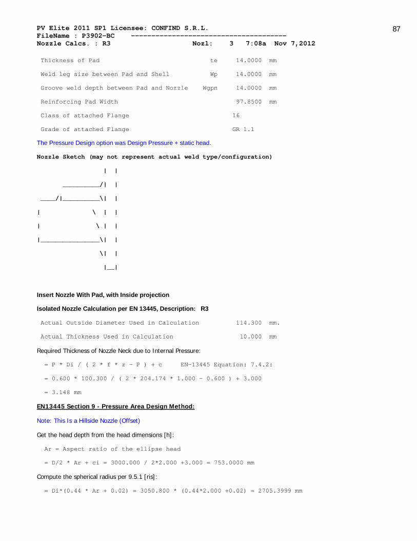
PV Elite 2011 SP1 Licensee: CONFIND S.R.L. FileName : P3902-BC -------------------------------------- Nozzle Calcs. : R3 Nozl: 3 7:08a Nov 7,2012
87
Thickness of Pad te 14.0000 mm
Weld leg size between Pad and Shell Wp 14.0000 mm
Groove weld depth between Pad and Nozzle Wgpn 14.0000 mm
Reinforcing Pad Width 97.8500 mm
Class of attached Flange 16
Grade of attached Flange GR 1.1
The Pressure Design option was Design Pressure + static head.
Nozzle Sketch (may not represent actual weld type/configuration)
| |
__________/| |
____/|__________\| |
| \ | |
| \ | |
|________________\| |
\| |
|__|
Insert Nozzle With Pad, with Inside projection
Isolated Nozzle Calculation per EN 13445, Description: R3
Actual Outside Diameter Used in Calculation 114.300 mm.
Actual Thickness Used in Calculation 10.000 mm
Required Thickness of Nozzle Neck due to Internal Pressure:
= P * Di / ( 2 * f * z - P ) + c EN-13445 Equation: 7.4.2:
= 0.600 * 100.300 / ( 2 * 204.174 * 1.000 - 0.600 ) + 3.000
= 3.148 mm
EN13445 Section 9 - Pressure Area Design Method:
Note: This Is a Hillside Nozzle (Offset)
Get the head depth from the head dimensions [h]:
Ar = Aspect ratio of the ellipse head
= D/2 * Ar + ci = 3000.000 / 2*2.000 +3.000 = 753.0000 mm
Compute the spherical radius per 9.5.1 [ris]:
= Di*(0.44 * Ar + 0.02) = 3050.800 * (0.44*2.000 +0.02) = 2705.3999 mm
PV Elite 2011 SP1 Licensee: CONFIND S.R.L. FileName : P3902-BC -------------------------------------- Nozzle Calcs. : R3 Nozl: 3 7:08a Nov 7,2012
88
Credit Distance Along the Shell per 9.5.1 [Iso]:
= Sqrt((2*ris+eas)*eas) = Sqrt(2*2705.400 + 11.000 ) * 11.000 )
= 244.2126 mm
Credit Distance Along the Nozzle outside per 9.5.7.1 [Ibo]:
= min( sqrt( ( de - eab )*eab ), ho )
= min( sqrt((114.3000 - 7.0000 )*7.0000 , 250.0000 )
= 27.4062 mm
Credit Distance Along the Nozzle per inside 9.5.7.1 [Ibi]:
= Min(hi, 0.50 * Ibo) = Min(100.000 , 0.50 * 27.406 ) = 13.7031 mm
Mean radius of Head per Figure 9.4-10 [rm]:
= ris + eas / 2 = 2705.400 + 11.000 / 2 = 2710.8999 mm
Angle subtending 'a' in figure 9.5-3 [Alpha]:
= asin( Offset / Rm ) - asin( ( Offset - 0.5 * dib) / Rm )
= asin(1200.000 /2710.900 )-asin((1200.000 -0.5*114.300 )/2710.900 )
= 0.0234 radians
The distance as depicted in figure 9.5-3 [a]:
= Alpha * rms = 0.023 * 2710.900 = 63.3744 mm
Angle between nozzle centreling and head centrline [Beta]:
= Asin(Offset / rms) = Asin(1200.000 )/2710.900 ) = 0.4586 radians
Small triangular area fig 9.5-3 [Ap_psi]:
= 0.5*dib²*tab(Beta) = 0.5*100.300²*Tan(0.459 ) = 2483.1152 mm²
Pressure area inside shell/head per 9.5-56 [Aps]:
= 0.5 * ris² * ( Iso + a ) / ( 0.5 * eas + ris ) + a * ( eas + eap )
= 0.5*2705.400 **2*(244.213 +63.374 )/(0.5*11.000 +2705.400 ) +
63.374 *(11.000 +14.000 ) = 416.8131 x 10^3 mm²
Area in the nozzle [Apb]:
= min(ho, Ibo)*dib*0.5 = min(250.000 , 27.406 )*100.300 *0.5
= 1374.4211 mm²
Afs = Iso * eas = 244.213 * 11.000 = 2686.3389 mm²
Afb = Ibo * eab + Ibi * Max(eab - cn + cnext, 0 )
= 27.406 * 7.000 + 13.703 * 0.000
= 246.6558 mm²

PV Elite 2011 SP1 Licensee: CONFIND S.R.L. FileName : P3902-BC -------------------------------------- Nozzle Calcs. : R3 Nozl: 3 7:08a Nov 7,2012
89
Afp = Ip * eap = 97.850 * 14.000 = 1369.9000 mm²
Afw = 196.0000 mm²
Calculation per paragraph 9.5.2.1.1 [fob, fop]:
fob = Min(fs, fb) = Min(204.174 , 204.174 ) = 204.174 MPa
fop = Min(fs, fp) = Min(204.174 , 204.174 ) = 204.174 MPa
Pressure Area Check Term per paragraph 9.5.2.1.1 [Pa]:
= (Afs+Afw)*(fs-0.5P)+Afp*(Min(fs,fp) - 0.5P) + Afb(Min(fs,fb) - 0.5P)
= (2686.339 + 196.000 ) * (204.174 - 0.5 * 0.600 ) +
(1369.900 * (Min(204.174 , 204.174 ) - 0.50 * 0.600 ) +
(246.656 * (Min(204.174 , 204.174 ) - 0.50 * 0.600 )
= 917.1290 x 10^3 N
Stress Area term per paragraph 9.5.2.1.1 [Pa]:
= P * ( Aps + Apb + .5 * APpsi )
= 0.600 * ( 416813.156 + 1374.421 + 0.5*0.000 ) = 251.6361 x 10^3 N
Since Pa >= Fa, Code Requirements are satisfied.
The Drop for this Nozzle is : 29.0538 mm
The Cut Length for this Nozzle is, Drop + Ho + H + T : 394.6566 mm
For possible nozzle interference - See Nozzle Summary
PV Elite is a trademark of Intergraph CADWorx & Analysis Solutions, Inc. 2011

PV Elite 2011 SP1 Licensee: CONFIND S.R.L. FileName : P3902-BC -------------------------------------- Nozzle Calcs. : GV2a Nozl: 4 7:08a Nov 7,2012
90
INPUT VALUES, Nozzle Description: GV2a From : 20
Pressure for Reinforcement Calculations P 0.6000 MPa
Temperature for Internal Pressure Temp 60 C
Shell Material P355NH
Shell Allowable Stress at Temperature S 204.17 MPa
Shell Allowable Stress At Ambient Sa 204.17 MPa
Inside Diameter of Cylindrical Shell D 3000.00 mm
Shell Finished (Minimum) Thickness t 14.0000 mm
Shell Internal Corrosion Allowance c 3.0000 mm
Shell External Corrosion Allowance co 0.0000 mm
Distance from Bottom/Left Tangent 550.0000 mm
Type of Element Connected to the Shell : Nozzle
Nozzle Material P355NH
Allowable Stress at Temperature Sn 204.17 MPa
Allowable Stress At Ambient Sna 204.17 MPa
Diameter Basis (for tr calc only) OD
Layout Angle 0.00 deg
Diameter 508.0000 mm.
Size and Thickness Basis Actual
Actual Thickness tn 10.0000 mm
Flange Material P355NH
Flange Type Slip on
Corrosion Allowance can 3.0000 mm
Outside Projection ho 250.0000 mm
Weld leg size between Nozzle and Pad/Shell Wo 14.0000 mm
Groove weld depth between Nozzle and Vessel Wgnv 14.0000 mm
Inside Projection h 0.0000 mm
Weld leg size, Inside Element to Shell Wi 0.0000 mm
Pad Material P355NH
Pad Allowable Stress at Temperature Sp 204.17 MPa
Pad Allowable Stress At Ambient Spa 204.17 MPa
Diameter of Pad along vessel surface Dp 800.0000 mm
Thickness of Pad te 14.0000 mm

PV Elite 2011 SP1 Licensee: CONFIND S.R.L. FileName : P3902-BC -------------------------------------- Nozzle Calcs. : GV2a Nozl: 4 7:08a Nov 7,2012
91
Weld leg size between Pad and Shell Wp 6.0000 mm
Groove weld depth between Pad and Nozzle Wgpn 10.0000 mm
Reinforcing Pad Width 146.0000 mm
Class of attached Flange 10
Grade of attached Flange GR 1.1
The Pressure Design option was Design Pressure + static head.
Nozzle Sketch (may not represent actual weld type/configuration)
| |
| |
__________/| |
____/|__________\| |
| \ | |
| \ | |
|________________\|__|
Insert Nozzle With Pad, no Inside projection
Isolated Nozzle Calculation per EN 13445, Description: GV2a
Actual Outside Diameter Used in Calculation 508.000 mm.
Actual Thickness Used in Calculation 10.000 mm
Required Thickness of Nozzle Neck due to Internal Pressure:
= P * Di / ( 2 * f * z - P ) + c EN-13445 Equation: 7.4.2:
= 0.600 * 494.000 / ( 2 * 204.174 * 1.000 - 0.600 ) + 3.000
= 3.727 mm
EN13445 Section 9 - Pressure Area Design Method:
Inside Radius per paragraph 9.5.3 [ris]:
= ( Di + 2 * cs ) / 2 = ( 3000.000 + 2 * 3.000 ) / 2
= 1503.0000 mm
Credit Distance Along the Nozzle per 9.5.76 [Ibo]:
= min( sqrt( ( deb - 2 * cext - eab) * eab), ho )
= min(sqrt((508.000 -2*0.000 -7.000 )*7.000 ),250.000 )
= 59.2199 mm
Credit Distance Along the Nozzle per 9.5.77 [Ibi]:

PV Elite 2011 SP1 Licensee: CONFIND S.R.L. FileName : P3902-BC -------------------------------------- Nozzle Calcs. : GV2a Nozl: 4 7:08a Nov 7,2012
92
= Min(hi, 0.5*Ibo) = Min(0.000 , 05*59.220 )
= 0.0000 mm
Compute cone pressure area per Equation 9.5.36 [Aps]:
= 0.5*(Iso+a)*(2*ris+(Iso+a)*tan(Alpha))
= 0.5*(182.173 +247.000 )*(2*1503.000 +(182.173 +247.000 )*tan(0.00 ))
= 645047 mm²
Compute area in the re-pad [Afp]:
= Ip * ep = 146.000 * 14.000
= 2044.0001 mm²
Compute triangular area [Ap.psi]:
= dib² * tan(Psi) / 2 = 494.000² * tan(0.000 )
= 0.0000 mm²
Calculate the Pressure Area per 9.5-29 [Aps]:
Note: do (nozzle O/Dia.) taken as the diameter of the hole in the shell
= ris * (Iso + do / 2 ) * ris + do/2 *( eas + eap )
= ris * (182.173 + 508.000 /2)*1503.000 + 20.000 /2*(11.000 +14.000 )
= 661.9180 x 10^3 mm²
Pressure Area of Nozzle per using dib and Ibo [Apb]:
(This is an inserted nozzle)
= Ibo * dib / 2 = 59.220 * 494.000 / 2
= 14.6273 x 10^3 mm²
Compute the effective re-pad width [Ip]:
= Min( Max( Dp - 2 * cext - do/Cos(Phi), 0 ) / 2, Iso ) )
= Min(Max (800.000 -2.0*0.000 -508.000 /Cos(0.000 ), 0.0)/2.0, 182.173
= 146.0000 mm
Available Metal Areas per 9.5-78 to 9.5-81 [Afs, Afb, Afp, Afw]:
Note: The welds are considered in the corroded condition
Afs = (Iso + eab)*eas = (182.173 + 7.000 )*11.000 = 2003.9032 mm²
Afb = Ibo*eb+Ibi*(eb-ci+co)=59.220 *7.000 +0.000 *(7.000 -3.000 +0.000
= 414.5395 mm²
Afp = Ip * eap = 4.174 * 14.000 = 2044.0001 mm²
Afw = (wshell² + wpad² + winside²) / 2
= (14.0000² + 6.0000² + 0.0000²) / 2 = 116.0000 mm²

PV Elite 2011 SP1 Licensee: CONFIND S.R.L. FileName : P3902-BC -------------------------------------- Nozzle Calcs. : GV2a Nozl: 4 7:08a Nov 7,2012
93
Calculation per paragraph 9.5.2.1.1 [fob, fop]
fob = Min(fs, fb) = Min(204.174 , 204.174 ) = 204.174 MPa
fop = Min(fs, fp) = Min(204.174 , 204.174 ) = 204.174 MPa
Force requirement per paragraph 9.5.2.1.1 [Fa]:
= (Afs+Afw)*(fs-0.5P)+Afp*(Min(fs,fp) - 0.5P) + Afb(Min(fs,fb) - 0.5P)
= (2003.903 + 116.000 ) * (204.174 - 0.5 * 0.600 ) +
(2044.000 * (Min(204.174 , 204.174 ) - 0.50 * 0.600 ) +
(414.539 * (Min(204.174 , 204.174 ) - 0.50 * 0.600 )
= 933.3454 x 10^3 N
Force Term per 9.5.2.1.1 [Pa]:
= P * ( Aps + Apb + 0.5 * APpsi )
= 0.600 * ( 661918 + 14627.321 + 0.5*0.000 )
= 405.8927 x 10^3 N
Since Fa >= Pa, Code Requirements are satisfied.
The Drop for this Nozzle is : 21.6618 mm
The Cut Length for this Nozzle is, Drop + Ho + H + T : 285.6618 mm
For possible nozzle interference - See Nozzle Summary
PV Elite is a trademark of Intergraph CADWorx & Analysis Solutions, Inc. 2011

PV Elite 2011 SP1 Licensee: CONFIND S.R.L. FileName : P3902-BC -------------------------------------- Nozzle Calcs. : GV2b Nozl: 5 7:08a Nov 7,2012
94
INPUT VALUES, Nozzle Description: GV2b From : 20
Pressure for Reinforcement Calculations P 0.6000 MPa
Temperature for Internal Pressure Temp 60 C
Shell Material P355NH
Shell Allowable Stress at Temperature S 204.17 MPa
Shell Allowable Stress At Ambient Sa 204.17 MPa
Inside Diameter of Cylindrical Shell D 3000.00 mm
Shell Finished (Minimum) Thickness t 14.0000 mm
Shell Internal Corrosion Allowance c 3.0000 mm
Shell External Corrosion Allowance co 0.0000 mm
Distance from Bottom/Left Tangent 7999.9995 mm
Type of Element Connected to the Shell : Nozzle
Nozzle Material P355NH
Allowable Stress at Temperature Sn 204.17 MPa
Allowable Stress At Ambient Sna 204.17 MPa
Diameter Basis (for tr calc only) OD
Layout Angle 0.00 deg
Diameter 508.0000 mm.
Size and Thickness Basis Actual
Actual Thickness tn 10.0000 mm
Flange Material P355NH
Flange Type Slip on
Corrosion Allowance can 3.0000 mm
Outside Projection ho 250.0000 mm
Weld leg size between Nozzle and Pad/Shell Wo 14.0000 mm
Groove weld depth between Nozzle and Vessel Wgnv 14.0000 mm
Inside Projection h 0.0000 mm
Weld leg size, Inside Element to Shell Wi 0.0000 mm
Pad Material P355NH
Pad Allowable Stress at Temperature Sp 204.17 MPa
Pad Allowable Stress At Ambient Spa 204.17 MPa
Diameter of Pad along vessel surface Dp 800.0000 mm
Thickness of Pad te 14.0000 mm

PV Elite 2011 SP1 Licensee: CONFIND S.R.L. FileName : P3902-BC -------------------------------------- Nozzle Calcs. : GV2b Nozl: 5 7:08a Nov 7,2012
95
Weld leg size between Pad and Shell Wp 6.0000 mm
Groove weld depth between Pad and Nozzle Wgpn 10.0000 mm
Reinforcing Pad Width 146.0000 mm
Class of attached Flange 10
Grade of attached Flange GR 1.1
The Pressure Design option was Design Pressure + static head.
Nozzle Sketch (may not represent actual weld type/configuration)
| |
| |
__________/| |
____/|__________\| |
| \ | |
| \ | |
|________________\|__|
Insert Nozzle With Pad, no Inside projection
Isolated Nozzle Calculation per EN 13445, Description: GV2b
Actual Outside Diameter Used in Calculation 508.000 mm.
Actual Thickness Used in Calculation 10.000 mm
Required Thickness of Nozzle Neck due to Internal Pressure:
= P * Di / ( 2 * f * z - P ) + c EN-13445 Equation: 7.4.2:
= 0.600 * 494.000 / ( 2 * 204.174 * 1.000 - 0.600 ) + 3.000
= 3.727 mm
EN13445 Section 9 - Pressure Area Design Method:
Inside Radius per paragraph 9.5.3 [ris]:
= ( Di + 2 * cs ) / 2 = ( 3000.000 + 2 * 3.000 ) / 2
= 1503.0000 mm
Credit Distance Along the Nozzle per 9.5.76 [Ibo]:
= min( sqrt( ( deb - 2 * cext - eab) * eab), ho )
= min(sqrt((508.000 -2*0.000 -7.000 )*7.000 ),250.000 )
= 59.2199 mm
Credit Distance Along the Nozzle per 9.5.77 [Ibi]:
= Min(hi, 0.5*Ibo) = Min(0.000 , 05*59.220 )
= 0.0000 mm

PV Elite 2011 SP1 Licensee: CONFIND S.R.L. FileName : P3902-BC -------------------------------------- Nozzle Calcs. : GV2b Nozl: 5 7:08a Nov 7,2012
96
Compute cone pressure area per Equation 9.5.36 [Aps]:
= 0.5*(Iso+a)*(2*ris+(Iso+a)*tan(Alpha))
= 0.5*(182.173 +247.000 )*(2*1503.000 +(182.173 +247.000 )*tan(0.00 ))
= 645047 mm²
Compute area in the re-pad [Afp]:
= Ip * ep = 146.000 * 14.000
= 2044.0001 mm²
Compute triangular area [Ap.psi]:
= dib² * tan(Psi) / 2 = 494.000² * tan(0.000 )
= 0.0000 mm²
Calculate the Pressure Area per 9.5-29 [Aps]:
Note: do (nozzle O/Dia.) taken as the diameter of the hole in the shell
= ris * (Iso + do / 2 ) * ris + do/2 *( eas + eap )
= ris * (182.173 + 508.000 /2)*1503.000 + 20.000 /2*(11.000 +14.000 )
= 661.9180 x 10^3 mm²
Pressure Area of Nozzle per using dib and Ibo [Apb]:
(This is an inserted nozzle)
= Ibo * dib / 2 = 59.220 * 494.000 / 2
= 14.6273 x 10^3 mm²
Compute the effective re-pad width [Ip]:
= Min( Max( Dp - 2 * cext - do/Cos(Phi), 0 ) / 2, Iso ) )
= Min(Max (800.000 -2.0*0.000 -508.000 /Cos(0.000 ), 0.0)/2.0, 182.173
= 146.0000 mm
Available Metal Areas per 9.5-78 to 9.5-81 [Afs, Afb, Afp, Afw]:
Note: The welds are considered in the corroded condition
Afs = (Iso + eab)*eas = (182.173 + 7.000 )*11.000 = 2003.9032 mm²
Afb = Ibo*eb+Ibi*(eb-ci+co)=59.220 *7.000 +0.000 *(7.000 -3.000 +0.000
= 414.5395 mm²
Afp = Ip * eap = 4.174 * 14.000 = 2044.0001 mm²
Afw = (wshell² + wpad² + winside²) / 2
= (14.0000² + 6.0000² + 0.0000²) / 2 = 116.0000 mm²
Calculation per paragraph 9.5.2.1.1 [fob, fop]
fob = Min(fs, fb) = Min(204.174 , 204.174 ) = 204.174 MPa

PV Elite 2011 SP1 Licensee: CONFIND S.R.L. FileName : P3902-BC -------------------------------------- Nozzle Calcs. : GV2b Nozl: 5 7:08a Nov 7,2012
97
fop = Min(fs, fp) = Min(204.174 , 204.174 ) = 204.174 MPa
Force requirement per paragraph 9.5.2.1.1 [Fa]:
= (Afs+Afw)*(fs-0.5P)+Afp*(Min(fs,fp) - 0.5P) + Afb(Min(fs,fb) - 0.5P)
= (2003.903 + 116.000 ) * (204.174 - 0.5 * 0.600 ) +
(2044.000 * (Min(204.174 , 204.174 ) - 0.50 * 0.600 ) +
(414.539 * (Min(204.174 , 204.174 ) - 0.50 * 0.600 )
= 933.3454 x 10^3 N
Force Term per 9.5.2.1.1 [Pa]:
= P * ( Aps + Apb + 0.5 * APpsi )
= 0.600 * ( 661918 + 14627.321 + 0.5*0.000 )
= 405.8927 x 10^3 N
Since Fa >= Pa, Code Requirements are satisfied.
The Drop for this Nozzle is : 21.6618 mm
The Cut Length for this Nozzle is, Drop + Ho + H + T : 285.6618 mm
For possible nozzle interference - See Nozzle Summary
PV Elite is a trademark of Intergraph CADWorx & Analysis Solutions, Inc. 2011

PV Elite 2011 SP1 Licensee: CONFIND S.R.L. FileName : P3902-BC -------------------------------------- Nozzle Calcs. : M1 Nozl: 6 7:08a Nov 7,2012
98
INPUT VALUES, Nozzle Description: M1 From : 20
Pressure for Reinforcement Calculations P 0.6000 MPa
Temperature for Internal Pressure Temp 60 C
Shell Material P355NH
Shell Allowable Stress at Temperature S 204.17 MPa
Shell Allowable Stress At Ambient Sa 204.17 MPa
Inside Diameter of Cylindrical Shell D 3000.00 mm
Shell Finished (Minimum) Thickness t 14.0000 mm
Shell Internal Corrosion Allowance c 3.0000 mm
Shell External Corrosion Allowance co 0.0000 mm
Distance from Bottom/Left Tangent 3910.0002 mm
Type of Element Connected to the Shell : Nozzle
Nozzle Material P285QH
Allowable Stress at Temperature Sn 162.51 MPa
Allowable Stress At Ambient Sna 162.51 MPa
Diameter Basis (for tr calc only) OD
Layout Angle 0.00 deg
Diameter 51.0000 mm.
Size and Thickness Basis Actual
Actual Thickness tn 12.5000 mm
Corrosion Allowance can 3.0000 mm
Outside Projection ho 66.0000 mm
Weld leg size between Nozzle and Pad/Shell Wo 14.0000 mm
Groove weld depth between Nozzle and Vessel Wgnv 14.0000 mm
Inside Projection h 0.0000 mm
Weld leg size, Inside Element to Shell Wi 0.0000 mm
The Pressure Design option was Design Pressure + static head.

PV Elite 2011 SP1 Licensee: CONFIND S.R.L. FileName : P3902-BC -------------------------------------- Nozzle Calcs. : M1 Nozl: 6 7:08a Nov 7,2012
99
Nozzle Sketch (may not represent actual weld type/configuration)
| |
____________/| |
| \ | |
| \ | |
|____________\|__|
Insert Nozzle No Pad, no Inside projection
Isolated Nozzle Calculation per EN 13445, Description: M1
Actual Outside Diameter Used in Calculation 51.000 mm.
Actual Thickness Used in Calculation 12.500 mm
Required Thickness of Nozzle Neck due to Internal Pressure:
= P * Di / ( 2 * f * z - P ) + c EN-13445 Equation: 7.4.2:
= 0.600 * 32.000 / ( 2 * 162.506 * 0.000 - 0.600 ) + 3.000
= -29.000 mm
EN13445 Section 9 - Pressure Area Design Method:
Inside Radius per paragraph 9.5.3 [ris]:
= ( Di + 2 * cs ) / 2 = ( 3000.000 + 2 * 3.000 ) / 2
= 1503.0000 mm
Credit Distance Along the Nozzle per 9.5.76 [Ibo]:
= min( sqrt( ( deb - 2 * cext - eab) * eab), ho )
= min(sqrt((51.000 -2*0.000 -9.500 )*9.500 ),66.000 )
= 19.8557 mm
Credit Distance Along the Nozzle per 9.5.77 [Ibi]:
= Min(hi, 0.5*Ibo) = Min(0.000 , 05*19.856 )
= 0.0000 mm
Compute cone pressure area per Equation 9.5.36 [Aps]:
= 0.5*(Iso+a)*(2*ris+(Iso+a)*tan(Alpha))
= 0.5*(182.173 +16.000 )*(2*1503.000 +(182.173 +16.000 )*tan(0.00 ))
= 0.3E+06 mm²
Compute area in the re-pad [Afp]:
= Ip * ep = 0.000 * 0.000 = 0.0000 mm²

PV Elite 2011 SP1 Licensee: CONFIND S.R.L. FileName : P3902-BC -------------------------------------- Nozzle Calcs. : M1 Nozl: 6 7:08a Nov 7,2012
100
Compute triangular area [Ap.psi]:
= dib² * tan(Psi) / 2 = 32.000² * tan(0.000 )
= 0.0000 mm²
Calculate the Pressure Area per 9.5-29 [Aps]:
Note: do (nozzle O/Dia.) taken as the diameter of the hole in the shell
= ris * (Iso + do / 2 ) * ris + do/2 *( eas + eap )
= ris * (182.173 + 51.000 /2)*1503.000 + 2.008 /2*(11.000 +0.000 )
= 312.4130 x 10^3 mm²
Pressure Area of Nozzle per using dib and Ibo [Apb]:
(This is an inserted nozzle)
= Ibo * dib / 2 = 19.856 * 32.000 / 2
= 317.6917 mm²
Compute the effective re-pad width [Ip]:
= Min( Max( Dp - 2 * cext - do/Cos(Phi), 0 ) / 2, Iso ) )
= Min(Max (0.000 -2.0*0.000 -51.000 /Cos(0.000 ), 0.0)/2.0, 182.173 )
= 0.0000 mm
Available Metal Areas per 9.5-78 to 9.5-81 [Afs, Afb, Afp, Afw]:
Note: The welds are considered in the corroded condition
Afs = (Iso + eab)*eas = (182.173 + 9.500 )*11.000 = 2003.9032 mm²
Afb = Ibo*eb+Ibi*(eb-ci+co)=19.856 *9.500 +0.000 *(9.500 -3.000 +0.000
= 188.6294 mm²
Afp = Ip * eap = 0.270 * 0.000 = 0.0000 mm²
Afw = (wshell² + wpad² + winside²) / 2
= (14.0000² + 0.0000² + 0.0000²) / 2 = 98.0000 mm²
Note: There is No Reinforcement Pad
Calculation per paragraph 9.5.2.1.1 [fob, fop]
fob = Min(fs, fb) = Min(204.174 , 162.506 ) = 162.506 MPa
fop = Min(fs, fp) = Min(204.174 , 0.000 ) = 0.000 MPa
Force requirement per paragraph 9.5.2.1.1 [Fa]:
= (Afs+Afw)*(fs-0.5P)+Afp*(Min(fs,fp) - 0.5P) + Afb(Min(fs,fb) - 0.5P)
= (2003.903 + 98.000 ) * (204.174 - 0.5 * 0.600 ) +
(0.000 * (Min(204.174 , 0.000 ) - 0.50 * 0.600 ) +
(188.629 * (Min(204.174 , 162.506 ) - 0.50 * 0.600 )

PV Elite 2011 SP1 Licensee: CONFIND S.R.L. FileName : P3902-BC -------------------------------------- Nozzle Calcs. : M1 Nozl: 6 7:08a Nov 7,2012
101
= 459.0808 x 10^3 N
Force Term per 9.5.2.1.1 [Pa]:
= P * ( Aps + Apb + 0.5 * APpsi )
= 0.600 * ( 312413.000 + 317.692 + 0.5*0.000 )
= 187.6225 x 10^3 N
Since Fa >= Pa, Code Requirements are satisfied.
The Drop for this Nozzle is : 0.2168 mm
The Cut Length for this Nozzle is, Drop + Ho + H + T : 80.2168 mm
For possible nozzle interference - See Nozzle Summary
PV Elite is a trademark of Intergraph CADWorx & Analysis Solutions, Inc. 2011

PV Elite 2011 SP1 Licensee: CONFIND S.R.L. FileName : P3902-BC -------------------------------------- Nozzle Calcs. : R8 Nozl: 7 7:08a Nov 7,2012
102
INPUT VALUES, Nozzle Description: R8 From : 20
Pressure for Reinforcement Calculations P 0.6000 MPa
Temperature for Internal Pressure Temp 60 C
Shell Material P355NH
Shell Allowable Stress at Temperature S 204.17 MPa
Shell Allowable Stress At Ambient Sa 204.17 MPa
Inside Diameter of Cylindrical Shell D 3000.00 mm
Shell Finished (Minimum) Thickness t 14.0000 mm
Shell Internal Corrosion Allowance c 3.0000 mm
Shell External Corrosion Allowance co 0.0000 mm
Distance from Bottom/Left Tangent 6990.0000 mm
Type of Element Connected to the Shell : Nozzle
Nozzle Material P355NH
Allowable Stress at Temperature Sn 204.17 MPa
Allowable Stress At Ambient Sna 204.17 MPa
Diameter Basis (for tr calc only) OD
Layout Angle 0.00 deg
Diameter 168.3000 mm.
Size and Thickness Basis Actual
Actual Thickness tn 10.0000 mm
Flange Material P285QH
Flange Type Weld Neck Flange
Corrosion Allowance can 3.0000 mm
Outside Projection ho 145.0000 mm
Weld leg size between Nozzle and Pad/Shell Wo 14.0000 mm
Groove weld depth between Nozzle and Vessel Wgnv 14.0000 mm
Inside Projection h 0.0000 mm
Weld leg size, Inside Element to Shell Wi 0.0000 mm
Pad Material P355NH
Pad Allowable Stress at Temperature Sp 204.17 MPa
Pad Allowable Stress At Ambient Spa 204.17 MPa
Diameter of Pad along vessel surface Dp 310.0000 mm
Thickness of Pad te 14.0000 mm

PV Elite 2011 SP1 Licensee: CONFIND S.R.L. FileName : P3902-BC -------------------------------------- Nozzle Calcs. : R8 Nozl: 7 7:08a Nov 7,2012
103
Weld leg size between Pad and Shell Wp 14.0000 mm
Groove weld depth between Pad and Nozzle Wgpn 14.0000 mm
Reinforcing Pad Width 70.8500 mm
Class of attached Flange 16
Grade of attached Flange GR 1.1
The Pressure Design option was Design Pressure + static head.
Nozzle Sketch (may not represent actual weld type/configuration)
| |
| |
__________/| |
____/|__________\| |
| \ | |
| \ | |
|________________\|__|
Insert Nozzle With Pad, no Inside projection
Isolated Nozzle Calculation per EN 13445, Description: R8
Actual Outside Diameter Used in Calculation 168.300 mm.
Actual Thickness Used in Calculation 10.000 mm
Required Thickness of Nozzle Neck due to Internal Pressure:
= P * Di / ( 2 * f * z - P ) + c EN-13445 Equation: 7.4.2:
= 0.600 * 154.300 / ( 2 * 204.174 * 0.000 - 0.600 ) + 3.000
= -151.300 mm
EN13445 Section 9 - Pressure Area Design Method:
Inside Radius per paragraph 9.5.3 [ris]:
= ( Di + 2 * cs ) / 2 = ( 3000.000 + 2 * 3.000 ) / 2
= 1503.0000 mm
Credit Distance Along the Nozzle per 9.5.76 [Ibo]:
= min( sqrt( ( deb - 2 * cext - eab) * eab), ho )
= min(sqrt((168.300 -2*0.000 -7.000 )*7.000 ),145.000 )
= 33.6021 mm
Credit Distance Along the Nozzle per 9.5.77 [Ibi]:
= Min(hi, 0.5*Ibo) = Min(0.000 , 05*33.602 ) = 0.0000 mm

PV Elite 2011 SP1 Licensee: CONFIND S.R.L. FileName : P3902-BC -------------------------------------- Nozzle Calcs. : R8 Nozl: 7 7:08a Nov 7,2012
104
Compute cone pressure area per Equation 9.5.36 [Aps]:
= 0.5*(Iso+a)*(2*ris+(Iso+a)*tan(Alpha))
= 0.5*(182.173 +77.150 )*(2*1503.000 +(182.173 +77.150 )*tan(0.00 ))
= 0.4E+06 mm²
Compute area in the re-pad [Afp]:
= Ip * ep = 70.850 * 14.000
= 991.9000 mm²
Compute triangular area [Ap.psi]:
= dib² * tan(Psi) / 2 = 154.300² * tan(0.000 )
= 0.0000 mm²
Calculate the Pressure Area per 9.5-29 [Aps]:
Note: do (nozzle O/Dia.) taken as the diameter of the hole in the shell
= ris * (Iso + do / 2 ) * ris + do/2 *( eas + eap )
= ris * (182.173 + 168.300 /2)*1503.000 + 6.626 /2*(11.000 +14.000 )
= 402.3872 x 10^3 mm²
Pressure Area of Nozzle per using dib and Ibo [Apb]:
(This is an inserted nozzle)
= Ibo * dib / 2 = 33.602 * 154.300 / 2
= 2.5924 x 10^3 mm²
Compute the effective re-pad width [Ip]:
= Min( Max( Dp - 2 * cext - do/Cos(Phi), 0 ) / 2, Iso ) )
= Min(Max (310.000 -2.0*0.000 -168.300 /Cos(0.000 ), 0.0)/2.0, 182.173
= 70.8500 mm
Available Metal Areas per 9.5-78 to 9.5-81 [Afs, Afb, Afp, Afw]:
Note: The welds are considered in the corroded condition
Afs = (Iso + eab)*eas = (182.173 + 7.000 )*11.000 = 2003.9032 mm²
Afb = Ibo*eb+Ibi*(eb-ci+co)=33.602 *7.000 +0.000 *(7.000 -3.000 +0.000
= 235.2146 mm²
Afp = Ip * eap = 1.304 * 14.000 = 991.9000 mm²
Afw = (wshell² + wpad² + winside²) / 2
= (14.0000² + 14.0000² + 0.0000²) / 2 = 196.0000 mm²
Calculation per paragraph 9.5.2.1.1 [fob, fop]
fob = Min(fs, fb) = Min(204.174 , 204.174 ) = 204.174 MPa

PV Elite 2011 SP1 Licensee: CONFIND S.R.L. FileName : P3902-BC -------------------------------------- Nozzle Calcs. : R8 Nozl: 7 7:08a Nov 7,2012
105
fop = Min(fs, fp) = Min(204.174 , 204.174 ) = 204.174 MPa
Force requirement per paragraph 9.5.2.1.1 [Fa]:
= (Afs+Afw)*(fs-0.5P)+Afp*(Min(fs,fp) - 0.5P) + Afb(Min(fs,fb) - 0.5P)
= (2003.903 + 196.000 ) * (204.174 - 0.5 * 0.600 ) +
(991.900 * (Min(204.174 , 204.174 ) - 0.50 * 0.600 ) +
(235.215 * (Min(204.174 , 204.174 ) - 0.50 * 0.600 )
= 698.6199 x 10^3 N
Force Term per 9.5.2.1.1 [Pa]:
= P * ( Aps + Apb + 0.5 * APpsi )
= 0.600 * ( 402387.219 + 2592.401 + 0.5*0.000 )
= 242.9671 x 10^3 N
Since Fa >= Pa, Code Requirements are satisfied.
The Drop for this Nozzle is : 2.3623 mm
The Cut Length for this Nozzle is, Drop + Ho + H + T : 161.3623 mm
For possible nozzle interference - See Nozzle Summary
PV Elite is a trademark of Intergraph CADWorx & Analysis Solutions, Inc. 2011

PV Elite 2011 SP1 Licensee: CONFIND S.R.L. FileName : P3902-BC -------------------------------------- Nozzle Calcs. : R2 Nozl: 8 7:08a Nov 7,2012
106
INPUT VALUES, Nozzle Description: R2 From : 20
Pressure for Reinforcement Calculations P 0.6000 MPa
Temperature for Internal Pressure Temp 60 C
Shell Material P355NH
Shell Allowable Stress at Temperature S 204.17 MPa
Shell Allowable Stress At Ambient Sa 204.17 MPa
Inside Diameter of Cylindrical Shell D 3000.00 mm
Shell Finished (Minimum) Thickness t 14.0000 mm
Shell Internal Corrosion Allowance c 3.0000 mm
Shell External Corrosion Allowance co 0.0000 mm
Distance from Bottom/Left Tangent 9270.0000 mm
Type of Element Connected to the Shell : Nozzle
Nozzle Material P355NH
Allowable Stress at Temperature Sn 204.17 MPa
Allowable Stress At Ambient Sna 204.17 MPa
Diameter Basis (for tr calc only) OD
Layout Angle 0.00 deg
Diameter 168.3000 mm.
Size and Thickness Basis Actual
Actual Thickness tn 10.0000 mm
Flange Material P285QH
Flange Type Weld Neck Flange
Corrosion Allowance can 3.0000 mm
Outside Projection ho 145.0000 mm
Weld leg size between Nozzle and Pad/Shell Wo 14.0000 mm
Groove weld depth between Nozzle and Vessel Wgnv 14.0000 mm
Inside Projection h 0.0000 mm
Weld leg size, Inside Element to Shell Wi 0.0000 mm
Pad Material P355NH
Pad Allowable Stress at Temperature Sp 204.17 MPa
Pad Allowable Stress At Ambient Spa 204.17 MPa
Diameter of Pad along vessel surface Dp 310.0000 mm
Thickness of Pad te 14.0000 mm

PV Elite 2011 SP1 Licensee: CONFIND S.R.L. FileName : P3902-BC -------------------------------------- Nozzle Calcs. : R2 Nozl: 8 7:08a Nov 7,2012
107
Weld leg size between Pad and Shell Wp 14.0000 mm
Groove weld depth between Pad and Nozzle Wgpn 14.0000 mm
Reinforcing Pad Width 70.8500 mm
Class of attached Flange 16
Grade of attached Flange GR 1.1
The Pressure Design option was Design Pressure + static head.
Nozzle Sketch (may not represent actual weld type/configuration)
| |
| |
__________/| |
____/|__________\| |
| \ | |
| \ | |
|________________\|__|
Insert Nozzle With Pad, no Inside projection
Isolated Nozzle Calculation per EN 13445, Description: R2
Actual Outside Diameter Used in Calculation 168.300 mm.
Actual Thickness Used in Calculation 10.000 mm
Required Thickness of Nozzle Neck due to Internal Pressure:
= P * Di / ( 2 * f * z - P ) + c EN-13445 Equation: 7.4.2:
= 0.600 * 154.300 / ( 2 * 204.174 * 0.000 - 0.600 ) + 3.000
= -151.300 mm
EN13445 Section 9 - Pressure Area Design Method:
Inside Radius per paragraph 9.5.3 [ris]:
= ( Di + 2 * cs ) / 2 = ( 3000.000 + 2 * 3.000 ) / 2
= 1503.0000 mm
Credit Distance Along the Nozzle per 9.5.76 [Ibo]:
= min( sqrt( ( deb - 2 * cext - eab) * eab), ho )
= min(sqrt((168.300 -2*0.000 -7.000 )*7.000 ),145.000 )
= 33.6021 mm

PV Elite 2011 SP1 Licensee: CONFIND S.R.L. FileName : P3902-BC -------------------------------------- Nozzle Calcs. : R2 Nozl: 8 7:08a Nov 7,2012
108
Credit Distance Along the Nozzle per 9.5.77 [Ibi]:
= Min(hi, 0.5*Ibo) = Min(0.000 , 05*33.602 )
= 0.0000 mm
Compute cone pressure area per Equation 9.5.36 [Aps]:
= 0.5*(Iso+a)*(2*ris+(Iso+a)*tan(Alpha))
= 0.5*(182.173 +77.150 )*(2*1503.000 +(182.173 +77.150 )*tan(0.00 ))
= 0.4E+06 mm²
Compute area in the re-pad [Afp]:
= Ip * ep = 70.850 * 14.000
= 991.9000 mm²
Compute triangular area [Ap.psi]:
= dib² * tan(Psi) / 2 = 154.300² * tan(0.000 )
= 0.0000 mm²
Calculate the Pressure Area per 9.5-29 [Aps]:
Note: do (nozzle O/Dia.) taken as the diameter of the hole in the shell
= ris * (Iso + do / 2 ) * ris + do/2 *( eas + eap )
= ris * (182.173 + 168.300 /2)*1503.000 + 6.626 /2*(11.000 +14.000 )
= 402.3872 x 10^3 mm²
Pressure Area of Nozzle per using dib and Ibo [Apb]:
(This is an inserted nozzle)
= Ibo * dib / 2 = 33.602 * 154.300 / 2
= 2.5924 x 10^3 mm²
Compute the effective re-pad width [Ip]:
= Min( Max( Dp - 2 * cext - do/Cos(Phi), 0 ) / 2, Iso ) )
= Min(Max (310.000 -2.0*0.000 -168.300 /Cos(0.000 ), 0.0)/2.0, 182.173
= 70.8500 mm
Available Metal Areas per 9.5-78 to 9.5-81 [Afs, Afb, Afp, Afw]:
Note: The welds are considered in the corroded condition
Afs = (Iso + eab)*eas = (182.173 + 7.000 )*11.000 = 2003.9032 mm²
Afb = Ibo*eb+Ibi*(eb-ci+co)=33.602 *7.000 +0.000 *(7.000 -3.000 +0.000
= 235.2146 mm²
Afp = Ip * eap = 1.304 * 14.000 = 991.9000 mm²
Afw = (wshell² + wpad² + winside²) / 2 = (14.0000² + 14.0000² + 0.0000²) / 2 = 196.0000 mm²

PV Elite 2011 SP1 Licensee: CONFIND S.R.L. FileName : P3902-BC -------------------------------------- Nozzle Calcs. : R2 Nozl: 8 7:08a Nov 7,2012
109
Calculation per paragraph 9.5.2.1.1 [fob, fop]
fob = Min(fs, fb) = Min(204.174 , 204.174 ) = 204.174 MPa
fop = Min(fs, fp) = Min(204.174 , 204.174 ) = 204.174 MPa
Force requirement per paragraph 9.5.2.1.1 [Fa]:
= (Afs+Afw)*(fs-0.5P)+Afp*(Min(fs,fp) - 0.5P) + Afb(Min(fs,fb) - 0.5P)
= (2003.903 + 196.000 ) * (204.174 - 0.5 * 0.600 ) +
(991.900 * (Min(204.174 , 204.174 ) - 0.50 * 0.600 ) +
(235.215 * (Min(204.174 , 204.174 ) - 0.50 * 0.600 )
= 698.6199 x 10^3 N
Force Term per 9.5.2.1.1 [Pa]:
= P * ( Aps + Apb + 0.5 * APpsi )
= 0.600 * ( 402387.219 + 2592.401 + 0.5*0.000 )
= 242.9671 x 10^3 N
Since Fa >= Pa, Code Requirements are satisfied.
The Drop for this Nozzle is : 2.3623 mm
The Cut Length for this Nozzle is, Drop + Ho + H + T : 161.3623 mm
For possible nozzle interference - See Nozzle Summary
PV Elite is a trademark of Intergraph CADWorx & Analysis Solutions, Inc. 2011

PV Elite 2011 SP1 Licensee: CONFIND S.R.L. FileName : P3902-BC -------------------------------------- Nozzle Calcs. : R6 Nozl: 9 7:08a Nov 7,2012
110
INPUT VALUES, Nozzle Description: R6 From : 20
Pressure for Reinforcement Calculations P 0.6000 MPa
Temperature for Internal Pressure Temp 60 C
Shell Material P355NH
Shell Allowable Stress at Temperature S 204.17 MPa
Shell Allowable Stress At Ambient Sa 204.17 MPa
Inside Diameter of Cylindrical Shell D 3000.00 mm
Shell Finished (Minimum) Thickness t 14.0000 mm
Shell Internal Corrosion Allowance c 3.0000 mm
Shell External Corrosion Allowance co 0.0000 mm
Distance from Bottom/Left Tangent 10000.0010 mm
Type of Element Connected to the Shell : Nozzle
Nozzle Material P355NH
Allowable Stress at Temperature Sn 204.17 MPa
Allowable Stress At Ambient Sna 204.17 MPa
Diameter Basis (for tr calc only) OD
Layout Angle 0.00 deg
Diameter 219.1000 mm.
Size and Thickness Basis Actual
Actual Thickness tn 10.0000 mm
Flange Material P285QH
Flange Type Weld Neck Flange
Corrosion Allowance can 3.0000 mm
Outside Projection ho 145.0000 mm
Weld leg size between Nozzle and Pad/Shell Wo 14.0000 mm
Groove weld depth between Nozzle and Vessel Wgnv 14.0000 mm
Inside Projection h 0.0000 mm
Weld leg size, Inside Element to Shell Wi 0.0000 mm
Pad Material P355NH
Pad Allowable Stress at Temperature Sp 204.17 MPa
Pad Allowable Stress At Ambient Spa 204.17 MPa
Diameter of Pad along vessel surface Dp 400.0000 mm
Thickness of Pad te 14.0000 mm

PV Elite 2011 SP1 Licensee: CONFIND S.R.L. FileName : P3902-BC -------------------------------------- Nozzle Calcs. : R6 Nozl: 9 7:08a Nov 7,2012
111
Weld leg size between Pad and Shell Wp 14.0000 mm
Groove weld depth between Pad and Nozzle Wgpn 14.0000 mm
Reinforcing Pad Width 90.4500 mm
Class of attached Flange 16
Grade of attached Flange GR 1.1
The Pressure Design option was Design Pressure + static head.
Nozzle Sketch (may not represent actual weld type/configuration)
| |
| |
__________/| |
____/|__________\| |
| \ | |
| \ | |
|________________\|__|
Insert Nozzle With Pad, no Inside projection
Isolated Nozzle Calculation per EN 13445, Description: R6
Actual Outside Diameter Used in Calculation 219.100 mm.
Actual Thickness Used in Calculation 10.000 mm
Required Thickness of Nozzle Neck due to Internal Pressure:
= P * Di / ( 2 * f * z - P ) + c EN-13445 Equation: 7.4.2:
= 0.600 * 205.100 / ( 2 * 204.174 * 0.000 - 0.600 ) + 3.000
= -202.100 mm
EN13445 Section 9 - Pressure Area Design Method:
Inside Radius per paragraph 9.5.3 [ris]:
= ( Di + 2 * cs ) / 2 = ( 3000.000 + 2 * 3.000 ) / 2
= 1503.0000 mm
Credit Distance Along the Nozzle per 9.5.76 [Ibo]:
= min( sqrt( ( deb - 2 * cext - eab) * eab), ho )
= min(sqrt((219.100 -2*0.000 -7.000 )*7.000 ),145.000 )
= 38.5318 mm
Credit Distance Along the Nozzle per 9.5.77 [Ibi]:
= Min(hi, 0.5*Ibo) = Min(0.000 , 05*38.532 )
= 0.0000 mm

PV Elite 2011 SP1 Licensee: CONFIND S.R.L. FileName : P3902-BC -------------------------------------- Nozzle Calcs. : R6 Nozl: 9 7:08a Nov 7,2012
112
Compute cone pressure area per Equation 9.5.36 [Aps]:
= 0.5*(Iso+a)*(2*ris+(Iso+a)*tan(Alpha))
= 0.5*(182.173 +102.550 )*(2*1503.000 +(182.173 +102.550 )*tan(0.00 ))
= 0.4E+06 mm²
Compute area in the re-pad [Afp]:
= Ip * ep = 90.450 * 14.000
= 1266.3000 mm²
Compute triangular area [Ap.psi]:
= dib² * tan(Psi) / 2 = 205.100² * tan(0.000 )
= 0.0000 mm²
Calculate the Pressure Area per 9.5-29 [Aps]:
Note: do (nozzle O/Dia.) taken as the diameter of the hole in the shell
= ris * (Iso + do / 2 ) * ris + do/2 *( eas + eap )
= ris * (182.173 + 219.100 /2)*1503.000 + 8.626 /2*(11.000 +14.000 )
= 441.1984 x 10^3 mm²
Pressure Area of Nozzle per using dib and Ibo [Apb]:
(This is an inserted nozzle)
= Ibo * dib / 2 = 38.532 * 205.100 / 2
= 3.9514 x 10^3 mm²
Compute the effective re-pad width [Ip]:
= Min( Max( Dp - 2 * cext - do/Cos(Phi), 0 ) / 2, Iso ) )
= Min(Max (400.000 -2.0*0.000 -219.100 /Cos(0.000 ), 0.0)/2.0, 182.173
= 90.4500 mm
Available Metal Areas per 9.5-78 to 9.5-81 [Afs, Afb, Afp, Afw]:
Note: The welds are considered in the corroded condition
Afs = (Iso + eab)*eas = (182.173 + 7.000 )*11.000 = 2003.9032 mm²
Afb = Ibo*eb+Ibi*(eb-ci+co)=38.532 *7.000 +0.000 *(7.000 -3.000 +0.000
= 269.7226 mm²
Afp = Ip * eap = 1.733 * 14.000 = 1266.3000 mm²
Afw = (wshell² + wpad² + winside²) / 2
= (14.0000² + 14.0000² + 0.0000²) / 2 = 196.0000 mm²
Calculation per paragraph 9.5.2.1.1 [fob, fop]
fob = Min(fs, fb) = Min(204.174 , 204.174 ) = 204.174 MPa

PV Elite 2011 SP1 Licensee: CONFIND S.R.L. FileName : P3902-BC -------------------------------------- Nozzle Calcs. : R6 Nozl: 9 7:08a Nov 7,2012
113
fop = Min(fs, fp) = Min(204.174 , 204.174 ) = 204.174 MPa
Force requirement per paragraph 9.5.2.1.1 [Fa]:
= (Afs+Afw)*(fs-0.5P)+Afp*(Min(fs,fp) - 0.5P) + Afb(Min(fs,fb) - 0.5P)
= (2003.903 + 196.000 ) * (204.174 - 0.5 * 0.600 ) +
(1266.300 * (Min(204.174 , 204.174 ) - 0.50 * 0.600 ) +
(269.723 * (Min(204.174 , 204.174 ) - 0.50 * 0.600 )
= 761.5928 x 10^3 N
Force Term per 9.5.2.1.1 [Pa]:
= P * ( Aps + Apb + 0.5 * APpsi )
= 0.600 * ( 441198.406 + 3951.437 + 0.5*0.000 )
= 267.0672 x 10^3 N
Since Fa >= Pa, Code Requirements are satisfied.
The Drop for this Nozzle is : 4.0058 mm
The Cut Length for this Nozzle is, Drop + Ho + H + T : 163.0058 mm
For possible nozzle interference - See Nozzle Summary
PV Elite is a trademark of Intergraph CADWorx & Analysis Solutions, Inc. 2011

PV Elite 2011 SP1 Licensee: CONFIND S.R.L. FileName : P3902-BC -------------------------------------- Nozzle Calcs. : R7c Nozl: 10 7:08a Nov 7,2012
114
INPUT VALUES, Nozzle Description: R7c From : 20
Pressure for Reinforcement Calculations P 0.6000 MPa
Temperature for Internal Pressure Temp 60 C
Shell Material P355NH
Shell Allowable Stress at Temperature S 204.17 MPa
Shell Allowable Stress At Ambient Sa 204.17 MPa
Inside Diameter of Cylindrical Shell D 3000.00 mm
Shell Finished (Minimum) Thickness t 14.0000 mm
Shell Internal Corrosion Allowance c 3.0000 mm
Shell External Corrosion Allowance co 0.0000 mm
Distance from Bottom/Left Tangent 300.0000 mm
Type of Element Connected to the Shell : Nozzle
Nozzle Material P355NH
Allowable Stress at Temperature Sn 204.17 MPa
Allowable Stress At Ambient Sna 204.17 MPa
Diameter Basis (for tr calc only) OD
Layout Angle 180.00 deg
Diameter 168.3000 mm.
Size and Thickness Basis Actual
Actual Thickness tn 10.0000 mm
Flange Material P285QH
Flange Type Weld Neck Flange
Corrosion Allowance can 3.0000 mm
Outside Projection ho 100.0000 mm
Weld leg size between Nozzle and Pad/Shell Wo 14.0000 mm
Groove weld depth between Nozzle and Vessel Wgnv 14.0000 mm
Inside Projection h 0.0000 mm
Weld leg size, Inside Element to Shell Wi 0.0000 mm
Pad Material P355NH
Pad Allowable Stress at Temperature Sp 204.17 MPa
Pad Allowable Stress At Ambient Spa 204.17 MPa
Diameter of Pad along vessel surface Dp 310.0000 mm
Thickness of Pad te 14.0000 mm
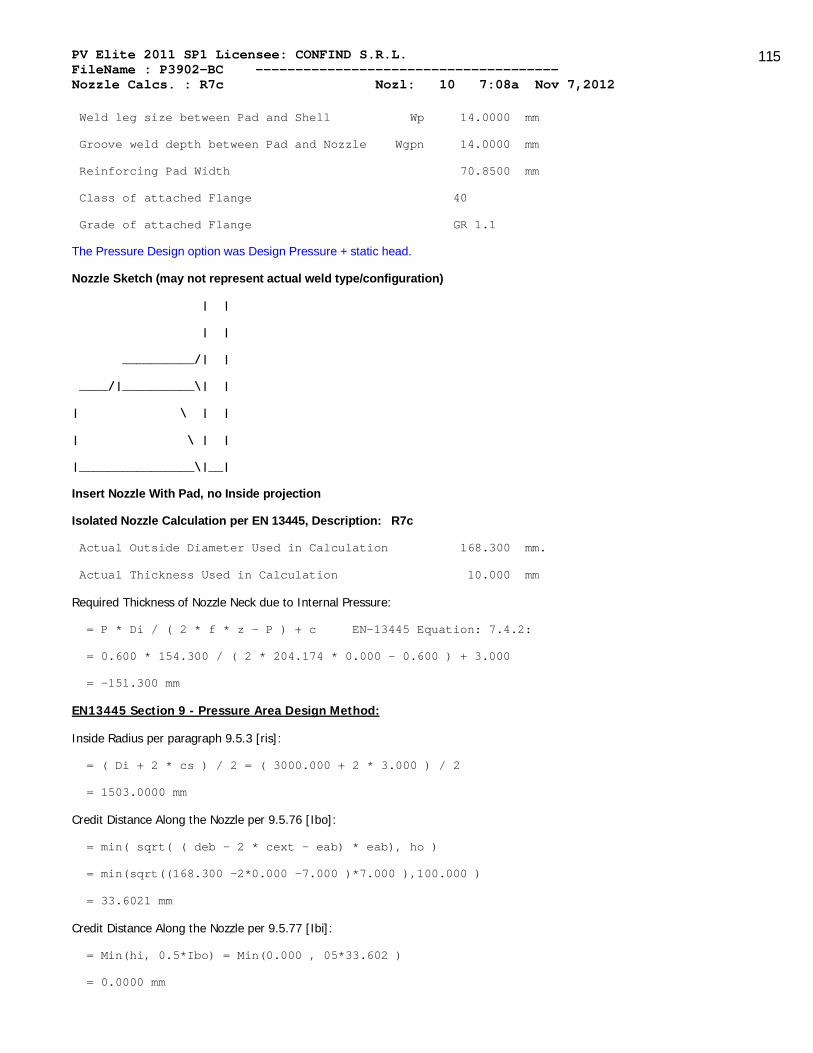
PV Elite 2011 SP1 Licensee: CONFIND S.R.L. FileName : P3902-BC -------------------------------------- Nozzle Calcs. : R7c Nozl: 10 7:08a Nov 7,2012
115
Weld leg size between Pad and Shell Wp 14.0000 mm
Groove weld depth between Pad and Nozzle Wgpn 14.0000 mm
Reinforcing Pad Width 70.8500 mm
Class of attached Flange 40
Grade of attached Flange GR 1.1
The Pressure Design option was Design Pressure + static head.
Nozzle Sketch (may not represent actual weld type/configuration)
| |
| |
__________/| |
____/|__________\| |
| \ | |
| \ | |
|________________\|__|
Insert Nozzle With Pad, no Inside projection
Isolated Nozzle Calculation per EN 13445, Description: R7c
Actual Outside Diameter Used in Calculation 168.300 mm.
Actual Thickness Used in Calculation 10.000 mm
Required Thickness of Nozzle Neck due to Internal Pressure:
= P * Di / ( 2 * f * z - P ) + c EN-13445 Equation: 7.4.2:
= 0.600 * 154.300 / ( 2 * 204.174 * 0.000 - 0.600 ) + 3.000
= -151.300 mm
EN13445 Section 9 - Pressure Area Design Method:
Inside Radius per paragraph 9.5.3 [ris]:
= ( Di + 2 * cs ) / 2 = ( 3000.000 + 2 * 3.000 ) / 2
= 1503.0000 mm
Credit Distance Along the Nozzle per 9.5.76 [Ibo]:
= min( sqrt( ( deb - 2 * cext - eab) * eab), ho )
= min(sqrt((168.300 -2*0.000 -7.000 )*7.000 ),100.000 )
= 33.6021 mm
Credit Distance Along the Nozzle per 9.5.77 [Ibi]:
= Min(hi, 0.5*Ibo) = Min(0.000 , 05*33.602 )
= 0.0000 mm

PV Elite 2011 SP1 Licensee: CONFIND S.R.L. FileName : P3902-BC -------------------------------------- Nozzle Calcs. : R7c Nozl: 10 7:08a Nov 7,2012
116
Compute cone pressure area per Equation 9.5.36 [Aps]:
= 0.5*(Iso+a)*(2*ris+(Iso+a)*tan(Alpha))
= 0.5*(182.173 +77.150 )*(2*1503.000 +(182.173 +77.150 )*tan(0.00 ))
= 0.4E+06 mm²
Compute area in the re-pad [Afp]:
= Ip * ep = 70.850 * 14.000
= 991.9000 mm²
Compute triangular area [Ap.psi]:
= dib² * tan(Psi) / 2 = 154.300² * tan(0.000 )
= 0.0000 mm²
Calculate the Pressure Area per 9.5-29 [Aps]:
Note: do (nozzle O/Dia.) taken as the diameter of the hole in the shell
= ris * (Iso + do / 2 ) * ris + do/2 *( eas + eap )
= ris * (182.173 + 168.300 /2)*1503.000 + 6.626 /2*(11.000 +14.000 )
= 402.3872 x 10^3 mm²
Pressure Area of Nozzle per using dib and Ibo [Apb]:
(This is an inserted nozzle)
= Ibo * dib / 2 = 33.602 * 154.300 / 2
= 2.5924 x 10^3 mm²
Compute the effective re-pad width [Ip]:
= Min( Max( Dp - 2 * cext - do/Cos(Phi), 0 ) / 2, Iso ) )
= Min(Max (310.000 -2.0*0.000 -168.300 /Cos(0.000 ), 0.0)/2.0, 182.173
= 70.8500 mm
Available Metal Areas per 9.5-78 to 9.5-81 [Afs, Afb, Afp, Afw]:
Note: The welds are considered in the corroded condition
Afs = (Iso + eab)*eas = (182.173 + 7.000 )*11.000 = 2003.9032 mm²
Afb = Ibo*eb+Ibi*(eb-ci+co)=33.602 *7.000 +0.000 *(7.000 -3.000 +0.000
= 235.2146 mm²
Afp = Ip * eap = 1.304 * 14.000 = 991.9000 mm²
Afw = (wshell² + wpad² + winside²) / 2
= (14.0000² + 14.0000² + 0.0000²) / 2 = 196.0000 mm²
Calculation per paragraph 9.5.2.1.1 [fob, fop]
fob = Min(fs, fb) = Min(204.174 , 204.174 ) = 204.174 MPa

PV Elite 2011 SP1 Licensee: CONFIND S.R.L. FileName : P3902-BC -------------------------------------- Nozzle Calcs. : R7c Nozl: 10 7:08a Nov 7,2012
117
fop = Min(fs, fp) = Min(204.174 , 204.174 ) = 204.174 MPa
Force requirement per paragraph 9.5.2.1.1 [Fa]:
= (Afs+Afw)*(fs-0.5P)+Afp*(Min(fs,fp) - 0.5P) + Afb(Min(fs,fb) - 0.5P)
= (2003.903 + 196.000 ) * (204.174 - 0.5 * 0.600 ) +
(991.900 * (Min(204.174 , 204.174 ) - 0.50 * 0.600 ) +
(235.215 * (Min(204.174 , 204.174 ) - 0.50 * 0.600 )
= 698.6199 x 10^3 N
Force Term per 9.5.2.1.1 [Pa]:
= P * ( Aps + Apb + 0.5 * APpsi )
= 0.600 * ( 402387.219 + 2592.401 + 0.5*0.000 )
= 242.9671 x 10^3 N
Since Fa >= Pa, Code Requirements are satisfied.
The Drop for this Nozzle is : 2.3623 mm
The Cut Length for this Nozzle is, Drop + Ho + H + T : 116.3623 mm
For possible nozzle interference - See Nozzle Summary
PV Elite is a trademark of Intergraph CADWorx & Analysis Solutions, Inc. 2011
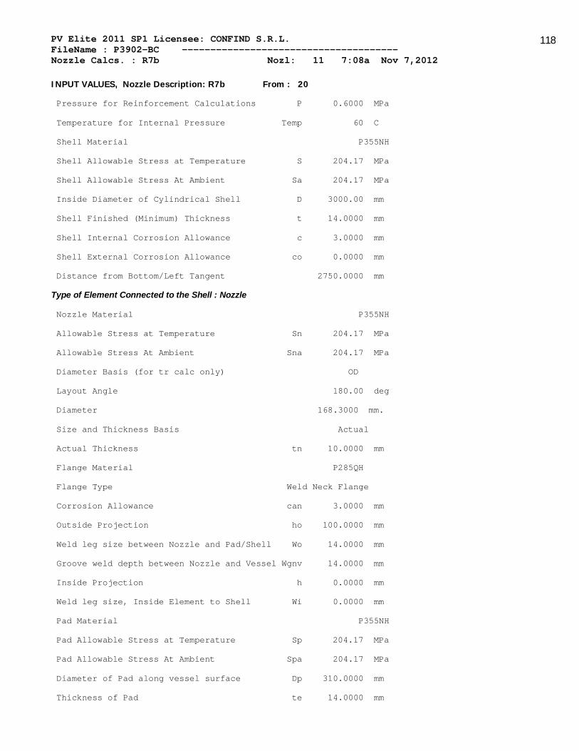
PV Elite 2011 SP1 Licensee: CONFIND S.R.L. FileName : P3902-BC -------------------------------------- Nozzle Calcs. : R7b Nozl: 11 7:08a Nov 7,2012
118
INPUT VALUES, Nozzle Description: R7b From : 20
Pressure for Reinforcement Calculations P 0.6000 MPa
Temperature for Internal Pressure Temp 60 C
Shell Material P355NH
Shell Allowable Stress at Temperature S 204.17 MPa
Shell Allowable Stress At Ambient Sa 204.17 MPa
Inside Diameter of Cylindrical Shell D 3000.00 mm
Shell Finished (Minimum) Thickness t 14.0000 mm
Shell Internal Corrosion Allowance c 3.0000 mm
Shell External Corrosion Allowance co 0.0000 mm
Distance from Bottom/Left Tangent 2750.0000 mm
Type of Element Connected to the Shell : Nozzle
Nozzle Material P355NH
Allowable Stress at Temperature Sn 204.17 MPa
Allowable Stress At Ambient Sna 204.17 MPa
Diameter Basis (for tr calc only) OD
Layout Angle 180.00 deg
Diameter 168.3000 mm.
Size and Thickness Basis Actual
Actual Thickness tn 10.0000 mm
Flange Material P285QH
Flange Type Weld Neck Flange
Corrosion Allowance can 3.0000 mm
Outside Projection ho 100.0000 mm
Weld leg size between Nozzle and Pad/Shell Wo 14.0000 mm
Groove weld depth between Nozzle and Vessel Wgnv 14.0000 mm
Inside Projection h 0.0000 mm
Weld leg size, Inside Element to Shell Wi 0.0000 mm
Pad Material P355NH
Pad Allowable Stress at Temperature Sp 204.17 MPa
Pad Allowable Stress At Ambient Spa 204.17 MPa
Diameter of Pad along vessel surface Dp 310.0000 mm
Thickness of Pad te 14.0000 mm
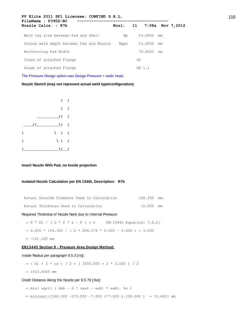
PV Elite 2011 SP1 Licensee: CONFIND S.R.L. FileName : P3902-BC -------------------------------------- Nozzle Calcs. : R7b Nozl: 11 7:08a Nov 7,2012
119
Weld leg size between Pad and Shell Wp 14.0000 mm
Groove weld depth between Pad and Nozzle Wgpn 14.0000 mm
Reinforcing Pad Width 70.8500 mm
Class of attached Flange 40
Grade of attached Flange GR 1.1
The Pressure Design option was Design Pressure + static head.
Nozzle Sketch (may not represent actual weld type/configuration)
| |
| |
__________/| |
____/|__________\| |
| \ | |
| \ | |
|________________\|__|
Insert Nozzle With Pad, no Inside projection
Isolated Nozzle Calculation per EN 13445, Description: R7b
Actual Outside Diameter Used in Calculation 168.300 mm.
Actual Thickness Used in Calculation 10.000 mm
Required Thickness of Nozzle Neck due to Internal Pressure:
= P * Di / ( 2 * f * z - P ) + c EN-13445 Equation: 7.4.2:
= 0.600 * 154.300 / ( 2 * 204.174 * 0.000 - 0.600 ) + 3.000
= -151.300 mm
EN13445 Section 9 - Pressure Area Design Method:
Inside Radius per paragraph 9.5.3 [ris]:
= ( Di + 2 * cs ) / 2 = ( 3000.000 + 2 * 3.000 ) / 2
= 1503.0000 mm
Credit Distance Along the Nozzle per 9.5.76 [Ibo]:
= min( sqrt( ( deb - 2 * cext - eab) * eab), ho )
= min(sqrt((168.300 -2*0.000 -7.000 )*7.000 ),100.000 ) = 33.6021 mm

PV Elite 2011 SP1 Licensee: CONFIND S.R.L. FileName : P3902-BC -------------------------------------- Nozzle Calcs. : R7b Nozl: 11 7:08a Nov 7,2012
120
Credit Distance Along the Nozzle per 9.5.77 [Ibi]:
= Min(hi, 0.5*Ibo) = Min(0.000 , 05*33.602 )
= 0.0000 mm
Compute cone pressure area per Equation 9.5.36 [Aps]:
= 0.5*(Iso+a)*(2*ris+(Iso+a)*tan(Alpha))
= 0.5*(182.173 +77.150 )*(2*1503.000 +(182.173 +77.150 )*tan(0.00 ))
= 0.4E+06 mm²
Compute area in the re-pad [Afp]:
= Ip * ep = 70.850 * 14.000
= 991.9000 mm²
Compute triangular area [Ap.psi]:
= dib² * tan(Psi) / 2 = 154.300² * tan(0.000 )
= 0.0000 mm²
Calculate the Pressure Area per 9.5-29 [Aps]:
Note: do (nozzle O/Dia.) taken as the diameter of the hole in the shell
= ris * (Iso + do / 2 ) * ris + do/2 *( eas + eap )
= ris * (182.173 + 168.300 /2)*1503.000 + 6.626 /2*(11.000 +14.000 )
= 402.3872 x 10^3 mm²
Pressure Area of Nozzle per using dib and Ibo [Apb]:
(This is an inserted nozzle)
= Ibo * dib / 2 = 33.602 * 154.300 / 2
= 2.5924 x 10^3 mm²
Compute the effective re-pad width [Ip]:
= Min( Max( Dp - 2 * cext - do/Cos(Phi), 0 ) / 2, Iso ) )
= Min(Max (310.000 -2.0*0.000 -168.300 /Cos(0.000 ), 0.0)/2.0, 182.173
= 70.8500 mm
Available Metal Areas per 9.5-78 to 9.5-81 [Afs, Afb, Afp, Afw]:
Note: The welds are considered in the corroded condition
Afs = (Iso + eab)*eas = (182.173 + 7.000 )*11.000 = 2003.9032 mm²
Afb = Ibo*eb+Ibi*(eb-ci+co)=33.602 *7.000 +0.000 *(7.000 -3.000 +0.000
= 235.2146 mm²
Afp = Ip * eap = 1.304 * 14.000 = 991.9000 mm²
Afw = (wshell² + wpad² + winside²) / 2 = (14.0000² + 14.0000² + 0.0000²) / 2 = 196.0000 mm²

PV Elite 2011 SP1 Licensee: CONFIND S.R.L. FileName : P3902-BC -------------------------------------- Nozzle Calcs. : R7b Nozl: 11 7:08a Nov 7,2012
121
Calculation per paragraph 9.5.2.1.1 [fob, fop]
fob = Min(fs, fb) = Min(204.174 , 204.174 ) = 204.174 MPa
fop = Min(fs, fp) = Min(204.174 , 204.174 ) = 204.174 MPa
Force requirement per paragraph 9.5.2.1.1 [Fa]:
= (Afs+Afw)*(fs-0.5P)+Afp*(Min(fs,fp) - 0.5P) + Afb(Min(fs,fb) - 0.5P)
= (2003.903 + 196.000 ) * (204.174 - 0.5 * 0.600 ) +
(991.900 * (Min(204.174 , 204.174 ) - 0.50 * 0.600 ) +
(235.215 * (Min(204.174 , 204.174 ) - 0.50 * 0.600 )
= 698.6199 x 10^3 N
Force Term per 9.5.2.1.1 [Pa]:
= P * ( Aps + Apb + 0.5 * APpsi )
= 0.600 * ( 402387.219 + 2592.401 + 0.5*0.000 )
= 242.9671 x 10^3 N
Since Fa >= Pa, Code Requirements are satisfied.
The Drop for this Nozzle is : 2.3623 mm
The Cut Length for this Nozzle is, Drop + Ho + H + T : 116.3623 mm
For possible nozzle interference - See Nozzle Summary
PV Elite is a trademark of Intergraph CADWorx & Analysis Solutions, Inc. 2011

PV Elite 2011 SP1 Licensee: CONFIND S.R.L. FileName : P3902-BC -------------------------------------- Nozzle Calcs. : R7a Nozl: 12 7:08a Nov 7,2012
122
INPUT VALUES, Nozzle Description: R7a From : 20
Pressure for Reinforcement Calculations P 0.6000 MPa
Temperature for Internal Pressure Temp 60 C
Shell Material P355NH
Shell Allowable Stress at Temperature S 204.17 MPa
Shell Allowable Stress At Ambient Sa 204.17 MPa
Inside Diameter of Cylindrical Shell D 3000.00 mm
Shell Finished (Minimum) Thickness t 14.0000 mm
Shell Internal Corrosion Allowance c 3.0000 mm
Shell External Corrosion Allowance co 0.0000 mm
Distance from Bottom/Left Tangent 7700.0000 mm
Type of Element Connected to the Shell : Nozzle
Nozzle Material P355NH
Allowable Stress at Temperature Sn 204.17 MPa
Allowable Stress At Ambient Sna 204.17 MPa
Diameter Basis (for tr calc only) OD
Layout Angle 180.00 deg
Diameter 168.3000 mm.
Size and Thickness Basis Actual
Actual Thickness tn 10.0000 mm
Flange Material P285QH
Flange Type Weld Neck Flange
Corrosion Allowance can 3.0000 mm
Outside Projection ho 100.0000 mm
Weld leg size between Nozzle and Pad/Shell Wo 14.0000 mm
Groove weld depth between Nozzle and Vessel Wgnv 14.0000 mm
Inside Projection h 0.0000 mm
Weld leg size, Inside Element to Shell Wi 0.0000 mm
Pad Material P355NH
Pad Allowable Stress at Temperature Sp 204.17 MPa
Pad Allowable Stress At Ambient Spa 204.17 MPa
Diameter of Pad along vessel surface Dp 310.0000 mm
Thickness of Pad te 14.0000 mm

PV Elite 2011 SP1 Licensee: CONFIND S.R.L. FileName : P3902-BC -------------------------------------- Nozzle Calcs. : R7a Nozl: 12 7:08a Nov 7,2012
123
Weld leg size between Pad and Shell Wp 14.0000 mm
Groove weld depth between Pad and Nozzle Wgpn 14.0000 mm
Reinforcing Pad Width 70.8500 mm
Class of attached Flange 40
Grade of attached Flange GR 1.1
The Pressure Design option was Design Pressure + static head.
Nozzle Sketch (may not represent actual weld type/configuration)
| |
| |
__________/| |
____/|__________\| |
| \ | |
| \ | |
|________________\|__|
Insert Nozzle With Pad, no Inside projection
Isolated Nozzle Calculation per EN 13445, Description: R7a
Actual Outside Diameter Used in Calculation 168.300 mm.
Actual Thickness Used in Calculation 10.000 mm
Required Thickness of Nozzle Neck due to Internal Pressure:
= P * Di / ( 2 * f * z - P ) + c EN-13445 Equation: 7.4.2:
= 0.600 * 154.300 / ( 2 * 204.174 * 0.000 - 0.600 ) + 3.000
= -151.300 mm
EN13445 Section 9 - Pressure Area Design Method:
Inside Radius per paragraph 9.5.3 [ris]:
= ( Di + 2 * cs ) / 2 = ( 3000.000 + 2 * 3.000 ) / 2
= 1503.0000 mm
Credit Distance Along the Nozzle per 9.5.76 [Ibo]:
= min( sqrt( ( deb - 2 * cext - eab) * eab), ho )
= min(sqrt((168.300 -2*0.000 -7.000 )*7.000 ),100.000 )
= 33.6021 mm
Credit Distance Along the Nozzle per 9.5.77 [Ibi]:
= Min(hi, 0.5*Ibo) = Min(0.000 , 05*33.602 )
= 0.0000 mm

PV Elite 2011 SP1 Licensee: CONFIND S.R.L. FileName : P3902-BC -------------------------------------- Nozzle Calcs. : R7a Nozl: 12 7:08a Nov 7,2012
124
Compute cone pressure area per Equation 9.5.36 [Aps]:
= 0.5*(Iso+a)*(2*ris+(Iso+a)*tan(Alpha))
= 0.5*(182.173 +77.150 )*(2*1503.000 +(182.173 +77.150 )*tan(0.00 ))
= 0.4E+06 mm²
Compute area in the re-pad [Afp]:
= Ip * ep = 70.850 * 14.000
= 991.9000 mm²
Compute triangular area [Ap.psi]:
= dib² * tan(Psi) / 2 = 154.300² * tan(0.000 )
= 0.0000 mm²
Calculate the Pressure Area per 9.5-29 [Aps]:
Note: do (nozzle O/Dia.) taken as the diameter of the hole in the shell
= ris * (Iso + do / 2 ) * ris + do/2 *( eas + eap )
= ris * (182.173 + 168.300 /2)*1503.000 + 6.626 /2*(11.000 +14.000 )
= 402.3872 x 10^3 mm²
Pressure Area of Nozzle per using dib and Ibo [Apb]:
(This is an inserted nozzle)
= Ibo * dib / 2 = 33.602 * 154.300 / 2
= 2.5924 x 10^3 mm²
Compute the effective re-pad width [Ip]:
= Min( Max( Dp - 2 * cext - do/Cos(Phi), 0 ) / 2, Iso ) )
= Min(Max (310.000 -2.0*0.000 -168.300 /Cos(0.000 ), 0.0)/2.0, 182.173
= 70.8500 mm
Available Metal Areas per 9.5-78 to 9.5-81 [Afs, Afb, Afp, Afw]:
Note: The welds are considered in the corroded condition
Afs = (Iso + eab)*eas = (182.173 + 7.000 )*11.000 = 2003.9032 mm²
Afb = Ibo*eb+Ibi*(eb-ci+co)=33.602 *7.000 +0.000 *(7.000 -3.000 +0.000
= 235.2146 mm²
Afp = Ip * eap = 1.304 * 14.000 = 991.9000 mm²
Afw = (wshell² + wpad² + winside²) / 2
= (14.0000² + 14.0000² + 0.0000²) / 2 = 196.0000 mm²
Calculation per paragraph 9.5.2.1.1 [fob, fop]
fob = Min(fs, fb) = Min(204.174 , 204.174 ) = 204.174 MPa
PV Elite 2011 SP1 Licensee: CONFIND S.R.L. FileName : P3902-BC -------------------------------------- Nozzle Calcs. : R7a Nozl: 12 7:08a Nov 7,2012
125
fop = Min(fs, fp) = Min(204.174 , 204.174 ) = 204.174 MPa
Force requirement per paragraph 9.5.2.1.1 [Fa]:
= (Afs+Afw)*(fs-0.5P)+Afp*(Min(fs,fp) - 0.5P) + Afb(Min(fs,fb) - 0.5P)
= (2003.903 + 196.000 ) * (204.174 - 0.5 * 0.600 ) +
(991.900 * (Min(204.174 , 204.174 ) - 0.50 * 0.600 ) +
(235.215 * (Min(204.174 , 204.174 ) - 0.50 * 0.600 )
= 698.6199 x 10^3 N
Force Term per 9.5.2.1.1 [Pa]:
= P * ( Aps + Apb + 0.5 * APpsi )
= 0.600 * ( 402387.219 + 2592.401 + 0.5*0.000 )
= 242.9671 x 10^3 N
Since Fa >= Pa, Code Requirements are satisfied.
The Drop for this Nozzle is : 2.3623 mm
The Cut Length for this Nozzle is, Drop + Ho + H + T : 116.3623 mm
For possible nozzle interference - See Nozzle Summary
PV Elite is a trademark of Intergraph CADWorx & Analysis Solutions, Inc. 2011

PV Elite 2011 SP1 Licensee: CONFIND S.R.L. FileName : P3902-BC -------------------------------------- Nozzle Calcs. : R5 Nozl: 13 7:08a Nov 7,2012
126
INPUT VALUES, Nozzle Description: R5 From : 20
Pressure for Reinforcement Calculations P 0.6000 MPa
Temperature for Internal Pressure Temp 60 C
Shell Material P355NH
Shell Allowable Stress at Temperature S 204.17 MPa
Shell Allowable Stress At Ambient Sa 204.17 MPa
Inside Diameter of Cylindrical Shell D 3000.00 mm
Shell Finished (Minimum) Thickness t 14.0000 mm
Shell Internal Corrosion Allowance c 3.0000 mm
Shell External Corrosion Allowance co 0.0000 mm
Distance from Bottom/Left Tangent 8960.0000 mm
Type of Element Connected to the Shell : Nozzle
Nozzle Material P355NH
Allowable Stress at Temperature Sn 204.17 MPa
Allowable Stress At Ambient Sna 204.17 MPa
Diameter Basis (for tr calc only) OD
Layout Angle 180.00 deg
Diameter 219.1000 mm.
Size and Thickness Basis Actual
Actual Thickness tn 10.0000 mm
Flange Material P285QH
Flange Type Weld Neck Flange
Corrosion Allowance can 3.0000 mm
Outside Projection ho 140.0000 mm
Weld leg size between Nozzle and Pad/Shell Wo 14.0000 mm
Groove weld depth between Nozzle and Vessel Wgnv 14.0000 mm
Inside Projection h 0.0000 mm
Weld leg size, Inside Element to Shell Wi 0.0000 mm
Pad Material P355NH
Pad Allowable Stress at Temperature Sp 204.17 MPa
Pad Allowable Stress At Ambient Spa 204.17 MPa
Diameter of Pad along vessel surface Dp 400.0000 mm
Thickness of Pad te 14.0000 mm

PV Elite 2011 SP1 Licensee: CONFIND S.R.L. FileName : P3902-BC -------------------------------------- Nozzle Calcs. : R5 Nozl: 13 7:08a Nov 7,2012
127
Weld leg size between Pad and Shell Wp 14.0000 mm
Groove weld depth between Pad and Nozzle Wgpn 14.0000 mm
Reinforcing Pad Width 90.4500 mm
Class of attached Flange 16
Grade of attached Flange GR 1.1
The Pressure Design option was Design Pressure + static head.
Nozzle Sketch (may not represent actual weld type/configuration)
| |
| |
__________/| |
____/|__________\| |
| \ | |
| \ | |
|________________\|__|
Insert Nozzle With Pad, no Inside projection
Isolated Nozzle Calculation per EN 13445, Description: R5
Actual Outside Diameter Used in Calculation 219.100 mm.
Actual Thickness Used in Calculation 10.000 mm
Required Thickness of Nozzle Neck due to Internal Pressure:
= P * Di / ( 2 * f * z - P ) + c EN-13445 Equation: 7.4.2:
= 0.600 * 205.100 / ( 2 * 204.174 * 0.000 - 0.600 ) + 3.000
= -202.100 mm
EN13445 Section 9 - Pressure Area Design Method:
Inside Radius per paragraph 9.5.3 [ris]:
= ( Di + 2 * cs ) / 2 = ( 3000.000 + 2 * 3.000 ) / 2
= 1503.0000 mm
Credit Distance Along the Nozzle per 9.5.76 [Ibo]:
= min( sqrt( ( deb - 2 * cext - eab) * eab), ho )
= min(sqrt((219.100 -2*0.000 -7.000 )*7.000 ),140.000 )
= 38.5318 mm
Credit Distance Along the Nozzle per 9.5.77 [Ibi]:
= Min(hi, 0.5*Ibo) = Min(0.000 , 05*38.532 ) = 0.0000 mm

PV Elite 2011 SP1 Licensee: CONFIND S.R.L. FileName : P3902-BC -------------------------------------- Nozzle Calcs. : R5 Nozl: 13 7:08a Nov 7,2012
128
Compute cone pressure area per Equation 9.5.36 [Aps]:
= 0.5*(Iso+a)*(2*ris+(Iso+a)*tan(Alpha))
= 0.5*(182.173 +102.550 )*(2*1503.000 +(182.173 +102.550 )*tan(0.00 ))
= 0.4E+06 mm²
Compute area in the re-pad [Afp]:
= Ip * ep = 90.450 * 14.000
= 1266.3000 mm²
Compute triangular area [Ap.psi]:
= dib² * tan(Psi) / 2 = 205.100² * tan(0.000 )
= 0.0000 mm²
Calculate the Pressure Area per 9.5-29 [Aps]:
Note: do (nozzle O/Dia.) taken as the diameter of the hole in the shell
= ris * (Iso + do / 2 ) * ris + do/2 *( eas + eap )
= ris * (182.173 + 219.100 /2)*1503.000 + 8.626 /2*(11.000 +14.000 )
= 441.1984 x 10^3 mm²
Pressure Area of Nozzle per using dib and Ibo [Apb]:
(This is an inserted nozzle)
= Ibo * dib / 2 = 38.532 * 205.100 / 2
= 3.9514 x 10^3 mm²
Compute the effective re-pad width [Ip]:
= Min( Max( Dp - 2 * cext - do/Cos(Phi), 0 ) / 2, Iso ) )
= Min(Max (400.000 -2.0*0.000 -219.100 /Cos(0.000 ), 0.0)/2.0, 182.173
= 90.4500 mm
Available Metal Areas per 9.5-78 to 9.5-81 [Afs, Afb, Afp, Afw]:
Note: The welds are considered in the corroded condition
Afs = (Iso + eab)*eas = (182.173 + 7.000 )*11.000 = 2003.9032 mm²
Afb = Ibo*eb+Ibi*(eb-ci+co)=38.532 *7.000 +0.000 *(7.000 -3.000 +0.000
= 269.7226 mm²
Afp = Ip * eap = 1.733 * 14.000 = 1266.3000 mm²
Afw = (wshell² + wpad² + winside²) / 2
= (14.0000² + 14.0000² + 0.0000²) / 2 = 196.0000 mm²
Calculation per paragraph 9.5.2.1.1 [fob, fop]
fob = Min(fs, fb) = Min(204.174 , 204.174 ) = 204.174 MPa

PV Elite 2011 SP1 Licensee: CONFIND S.R.L. FileName : P3902-BC -------------------------------------- Nozzle Calcs. : R5 Nozl: 13 7:08a Nov 7,2012
129
fop = Min(fs, fp) = Min(204.174 , 204.174 ) = 204.174 MPa
Force requirement per paragraph 9.5.2.1.1 [Fa]:
= (Afs+Afw)*(fs-0.5P)+Afp*(Min(fs,fp) - 0.5P) + Afb(Min(fs,fb) - 0.5P)
= (2003.903 + 196.000 ) * (204.174 - 0.5 * 0.600 ) +
(1266.300 * (Min(204.174 , 204.174 ) - 0.50 * 0.600 ) +
(269.723 * (Min(204.174 , 204.174 ) - 0.50 * 0.600 )
= 761.5928 x 10^3 N
Force Term per 9.5.2.1.1 [Pa]:
= P * ( Aps + Apb + 0.5 * APpsi )
= 0.600 * ( 441198.406 + 3951.437 + 0.5*0.000 )
= 267.0672 x 10^3 N
Since Fa >= Pa, Code Requirements are satisfied.
The Drop for this Nozzle is : 4.0058 mm
The Cut Length for this Nozzle is, Drop + Ho + H + T : 158.0058 mm
For possible nozzle interference - See Nozzle Summary
PV Elite is a trademark of Intergraph CADWorx & Analysis Solutions, Inc. 2011

PV Elite 2011 SP1 Licensee: CONFIND S.R.L. FileName : P3902-BC -------------------------------------- Nozzle Calcs. : R4 Nozl: 14 7:08a Nov 7,2012
130
INPUT VALUES, Nozzle Description: R4 From : 20
Pressure for Reinforcement Calculations P 0.6000 MPa
Temperature for Internal Pressure Temp 60 C
Shell Material P355NH
Shell Allowable Stress at Temperature S 204.17 MPa
Shell Allowable Stress At Ambient Sa 204.17 MPa
Inside Diameter of Cylindrical Shell D 3000.00 mm
Shell Finished (Minimum) Thickness t 14.0000 mm
Shell Internal Corrosion Allowance c 3.0000 mm
Shell External Corrosion Allowance co 0.0000 mm
Distance from Bottom/Left Tangent 10150.0010 mm
Type of Element Connected to the Shell : Nozzle
Nozzle Material P355NH
Allowable Stress at Temperature Sn 204.17 MPa
Allowable Stress At Ambient Sna 204.17 MPa
Diameter Basis (for tr calc only) OD
Layout Angle 180.00 deg
Diameter 168.3000 mm.
Size and Thickness Basis Actual
Actual Thickness tn 10.0000 mm
Flange Material P285QH
Flange Type Weld Neck Flange
Corrosion Allowance can 3.0000 mm
Outside Projection ho 145.0000 mm
Weld leg size between Nozzle and Pad/Shell Wo 14.0000 mm
Groove weld depth between Nozzle and Vessel Wgnv 14.0000 mm
Inside Projection h 0.0000 mm
Weld leg size, Inside Element to Shell Wi 0.0000 mm
Pad Material P355NH
Pad Allowable Stress at Temperature Sp 204.17 MPa
Pad Allowable Stress At Ambient Spa 204.17 MPa
Diameter of Pad along vessel surface Dp 310.0000 mm
Thickness of Pad te 14.0000 mm

PV Elite 2011 SP1 Licensee: CONFIND S.R.L. FileName : P3902-BC -------------------------------------- Nozzle Calcs. : R4 Nozl: 14 7:08a Nov 7,2012
131
Weld leg size between Pad and Shell Wp 14.0000 mm
Groove weld depth between Pad and Nozzle Wgpn 14.0000 mm
Reinforcing Pad Width 70.8500 mm
Class of attached Flange 16
Grade of attached Flange GR 1.1
The Pressure Design option was Design Pressure + static head.
Nozzle Sketch (may not represent actual weld type/configuration)
| |
__________/| |
____/|__________\| |
| \ | |
| \ | |
|________________\|__|
Insert Nozzle With Pad, no Inside projection
Isolated Nozzle Calculation per EN 13445, Description: R4
Actual Outside Diameter Used in Calculation 168.300 mm.
Actual Thickness Used in Calculation 10.000 mm
Required Thickness of Nozzle Neck due to Internal Pressure:
= P * Di / ( 2 * f * z - P ) + c EN-13445 Equation: 7.4.2:
= 0.600 * 154.300 / ( 2 * 204.174 * 0.000 - 0.600 ) + 3.000
= -151.300 mm
EN13445 Section 9 - Pressure Area Design Method:
Inside Radius per paragraph 9.5.3 [ris]:
= ( Di + 2 * cs ) / 2 = ( 3000.000 + 2 * 3.000 ) / 2
= 1503.0000 mm
Credit Distance Along the Nozzle per 9.5.76 [Ibo]:
= min( sqrt( ( deb - 2 * cext - eab) * eab), ho )
= min(sqrt((168.300 -2*0.000 -7.000 )*7.000 ),145.000 )
= 33.6021 mm
Credit Distance Along the Nozzle per 9.5.77 [Ibi]:
= Min(hi, 0.5*Ibo) = Min(0.000 , 05*33.602 )

PV Elite 2011 SP1 Licensee: CONFIND S.R.L. FileName : P3902-BC -------------------------------------- Nozzle Calcs. : R4 Nozl: 14 7:08a Nov 7,2012
132
= 0.0000 mm
Compute cone pressure area per Equation 9.5.36 [Aps]:
= 0.5*(Iso+a)*(2*ris+(Iso+a)*tan(Alpha))
= 0.5*(182.173 +77.150 )*(2*1503.000 +(182.173 +77.150 )*tan(0.00 ))
= 0.4E+06 mm²
Compute area in the re-pad [Afp]:
= Ip * ep = 70.850 * 14.000
= 991.9000 mm²
Compute triangular area [Ap.psi]:
= dib² * tan(Psi) / 2 = 154.300² * tan(0.000 )
= 0.0000 mm²
Calculate the Pressure Area per 9.5-29 [Aps]:
Note: do (nozzle O/Dia.) taken as the diameter of the hole in the shell
= ris * (Iso + do / 2 ) * ris + do/2 *( eas + eap )
= ris * (182.173 + 168.300 /2)*1503.000 + 6.626 /2*(11.000 +14.000 )
= 402.3872 x 10^3 mm²
Pressure Area of Nozzle per using dib and Ibo [Apb]:
(This is an inserted nozzle)
= Ibo * dib / 2 = 33.602 * 154.300 / 2
= 2.5924 x 10^3 mm²
Compute the effective re-pad width [Ip]:
= Min( Max( Dp - 2 * cext - do/Cos(Phi), 0 ) / 2, Iso ) )
= Min(Max (310.000 -2.0*0.000 -168.300 /Cos(0.000 ), 0.0)/2.0, 182.173
= 70.8500 mm
Available Metal Areas per 9.5-78 to 9.5-81 [Afs, Afb, Afp, Afw]:
Note: The welds are considered in the corroded condition
Afs = (Iso + eab)*eas = (182.173 + 7.000 )*11.000 = 2003.9032 mm²
Afb = Ibo*eb+Ibi*(eb-ci+co)=33.602 *7.000 +0.000 *(7.000 -3.000 +0.000
= 235.2146 mm²
Afp = Ip * eap = 1.304 * 14.000 = 991.9000 mm²
Afw = (wshell² + wpad² + winside²) / 2
= (14.0000² + 14.0000² + 0.0000²) / 2 = 196.0000 mm²

PV Elite 2011 SP1 Licensee: CONFIND S.R.L. FileName : P3902-BC -------------------------------------- Nozzle Calcs. : R4 Nozl: 14 7:08a Nov 7,2012
133
Calculation per paragraph 9.5.2.1.1 [fob, fop]
fob = Min(fs, fb) = Min(204.174 , 204.174 ) = 204.174 MPa
fop = Min(fs, fp) = Min(204.174 , 204.174 ) = 204.174 MPa
Force requirement per paragraph 9.5.2.1.1 [Fa]:
= (Afs+Afw)*(fs-0.5P)+Afp*(Min(fs,fp) - 0.5P) + Afb(Min(fs,fb) - 0.5P)
= (2003.903 + 196.000 ) * (204.174 - 0.5 * 0.600 ) +
(991.900 * (Min(204.174 , 204.174 ) - 0.50 * 0.600 ) +
(235.215 * (Min(204.174 , 204.174 ) - 0.50 * 0.600 )
= 698.6199 x 10^3 N
Force Term per 9.5.2.1.1 [Pa]:
= P * ( Aps + Apb + 0.5 * APpsi )
= 0.600 * ( 402387.219 + 2592.401 + 0.5*0.000 )
= 242.9671 x 10^3 N
Since Fa >= Pa, Code Requirements are satisfied.
The Drop for this Nozzle is : 2.3623 mm
The Cut Length for this Nozzle is, Drop + Ho + H + T : 161.3623 mm
For possible nozzle interference - See Nozzle Summary
PV Elite is a trademark of Intergraph CADWorx & Analysis Solutions, Inc. 2011

PV Elite 2011 SP1 Licensee: CONFIND S.R.L. FileName : P3902-BC -------------------------------------- Nozzle Calcs. : R17b Nozl: 15 7:08a Nov 7,2012
134
INPUT VALUES, Nozzle Description: R17b From : 20
Pressure for Reinforcement Calculations P 0.6000 MPa
Temperature for Internal Pressure Temp 60 C
Shell Material P355NH
Shell Allowable Stress at Temperature S 204.17 MPa
Shell Allowable Stress At Ambient Sa 204.17 MPa
Inside Diameter of Cylindrical Shell D 3000.00 mm
Shell Finished (Minimum) Thickness t 14.0000 mm
Shell Internal Corrosion Allowance c 3.0000 mm
Shell External Corrosion Allowance co 0.0000 mm
Distance from Bottom/Left Tangent 8700.0000 mm
Type of Element Connected to the Shell : Nozzle
Nozzle Material P285QH
Allowable Stress at Temperature Sn 162.51 MPa
Allowable Stress At Ambient Sna 162.51 MPa
Diameter Basis (for tr calc only) OD
Layout Angle 180.00 deg
Diameter 51.0000 mm.
Size and Thickness Basis Actual
Actual Thickness tn 12.5000 mm
Flange Material P285QH
Flange Type Weld Neck Flange
Corrosion Allowance can 3.0000 mm
Outside Projection ho 60.0000 mm
Weld leg size between Nozzle and Pad/Shell Wo 14.0000 mm
Groove weld depth between Nozzle and Vessel Wgnv 14.0000 mm
Inside Projection h 0.0000 mm
Weld leg size, Inside Element to Shell Wi 0.0000 mm
Class of attached Flange 40
Grade of attached Flange GR 1.1
The Pressure Design option was Design Pressure + static head.

PV Elite 2011 SP1 Licensee: CONFIND S.R.L. FileName : P3902-BC -------------------------------------- Nozzle Calcs. : R17b Nozl: 15 7:08a Nov 7,2012
135
Nozzle Sketch (may not represent actual weld type/configuration)
| |
| |
____________/| |
| \ | |
| \ | |
|____________\|__|
Insert Nozzle No Pad, no Inside projection
Isolated Nozzle Calculation per EN 13445, Description: R17b
Actual Outside Diameter Used in Calculation 51.000 mm.
Actual Thickness Used in Calculation 12.500 mm
Required Thickness of Nozzle Neck due to Internal Pressure:
= P * Di / ( 2 * f * z - P ) + c EN-13445 Equation: 7.4.2:
= 0.600 * 32.000 / ( 2 * 162.506 * 0.000 - 0.600 ) + 3.000
= -29.000 mm
EN13445 Section 9 - Pressure Area Design Method:
Inside Radius per paragraph 9.5.3 [ris]:
= ( Di + 2 * cs ) / 2 = ( 3000.000 + 2 * 3.000 ) / 2
= 1503.0000 mm
Credit Distance Along the Nozzle per 9.5.76 [Ibo]:
= min( sqrt( ( deb - 2 * cext - eab) * eab), ho )
= min(sqrt((51.000 -2*0.000 -9.500 )*9.500 ),60.000 )
= 19.8557 mm
Credit Distance Along the Nozzle per 9.5.77 [Ibi]:
= Min(hi, 0.5*Ibo) = Min(0.000 , 05*19.856 )
= 0.0000 mm
Compute cone pressure area per Equation 9.5.36 [Aps]:
= 0.5*(Iso+a)*(2*ris+(Iso+a)*tan(Alpha))
= 0.5*(182.173 +16.000 )*(2*1503.000 +(182.173 +16.000 )*tan(0.00 ))
= 0.3E+06 mm²
PV Elite 2011 SP1 Licensee: CONFIND S.R.L. FileName : P3902-BC -------------------------------------- Nozzle Calcs. : R17b Nozl: 15 7:08a Nov 7,2012
136
Compute area in the re-pad [Afp]:
= Ip * ep = 0.000 * 0.000
= 0.0000 mm²
Compute triangular area [Ap.psi]:
= dib² * tan(Psi) / 2 = 32.000² * tan(0.000 )
= 0.0000 mm²
Calculate the Pressure Area per 9.5-29 [Aps]:
Note: do (nozzle O/Dia.) taken as the diameter of the hole in the shell
= ris * (Iso + do / 2 ) * ris + do/2 *( eas + eap )
= ris * (182.173 + 51.000 /2)*1503.000 + 2.008 /2*(11.000 +0.000 )
= 312.4130 x 10^3 mm²
Pressure Area of Nozzle per using dib and Ibo [Apb]:
(This is an inserted nozzle)
= Ibo * dib / 2 = 19.856 * 32.000 / 2
= 317.6917 mm²
Compute the effective re-pad width [Ip]:
= Min( Max( Dp - 2 * cext - do/Cos(Phi), 0 ) / 2, Iso ) )
= Min(Max (0.000 -2.0*0.000 -51.000 /Cos(0.000 ), 0.0)/2.0, 182.173 )
= 0.0000 mm
Available Metal Areas per 9.5-78 to 9.5-81 [Afs, Afb, Afp, Afw]:
Note: The welds are considered in the corroded condition
Afs = (Iso + eab)*eas = (182.173 + 9.500 )*11.000 = 2003.9032 mm²
Afb = Ibo*eb+Ibi*(eb-ci+co)=19.856 *9.500 +0.000 *(9.500 -3.000 +0.000
= 188.6294 mm²
Afp = Ip * eap = 0.270 * 0.000 = 0.0000 mm²
Afw = (wshell² + wpad² + winside²) / 2
= (14.0000² + 0.0000² + 0.0000²) / 2 = 98.0000 mm²
Note: There is No Reinforcement Pad
Calculation per paragraph 9.5.2.1.1 [fob, fop]
fob = Min(fs, fb) = Min(204.174 , 162.506 ) = 162.506 MPa
fop = Min(fs, fp) = Min(204.174 , 0.000 ) = 0.000 MPa
Force requirement per paragraph 9.5.2.1.1 [Fa]:
= (Afs+Afw)*(fs-0.5P)+Afp*(Min(fs,fp) - 0.5P) + Afb(Min(fs,fb) - 0.5P)

PV Elite 2011 SP1 Licensee: CONFIND S.R.L. FileName : P3902-BC -------------------------------------- Nozzle Calcs. : R17b Nozl: 15 7:08a Nov 7,2012
137
= (2003.903 + 98.000 ) * (204.174 - 0.5 * 0.600 ) +
(0.000 * (Min(204.174 , 0.000 ) - 0.50 * 0.600 ) +
(188.629 * (Min(204.174 , 162.506 ) - 0.50 * 0.600 )
= 459.0808 x 10^3 N
Force Term per 9.5.2.1.1 [Pa]:
= P * ( Aps + Apb + 0.5 * APpsi )
= 0.600 * ( 312413.000 + 317.692 + 0.5*0.000 )
= 187.6225 x 10^3 N
Since Fa >= Pa, Code Requirements are satisfied.
The Drop for this Nozzle is : 0.2168 mm
The Cut Length for this Nozzle is, Drop + Ho + H + T : 74.2168 mm
For possible nozzle interference - See Nozzle Summary
PV Elite is a trademark of Intergraph CADWorx & Analysis Solutions, Inc. 2011

PV Elite 2011 SP1 Licensee: CONFIND S.R.L. FileName : P3902-BC -------------------------------------- Nozzle Calcs. : R17d Nozl: 16 7:08a Nov 7,2012
138
INPUT VALUES, Nozzle Description: R17d From : 20
Pressure for Reinforcement Calculations P 0.6000 MPa
Temperature for Internal Pressure Temp 60 C
Shell Material P355NH
Shell Allowable Stress at Temperature S 204.17 MPa
Shell Allowable Stress At Ambient Sa 204.17 MPa
Inside Diameter of Cylindrical Shell D 3000.00 mm
Shell Finished (Minimum) Thickness t 14.0000 mm
Shell Internal Corrosion Allowance c 3.0000 mm
Shell External Corrosion Allowance co 0.0000 mm
Distance from Cylinder/Cone Centerline L1 500.0000 mm
Distance from Bottom/Left Tangent 10290.0010 mm
Type of Element Connected to the Shell : Nozzle
Nozzle Material P285QH
Allowable Stress at Temperature Sn 162.51 MPa
Allowable Stress At Ambient Sna 162.51 MPa
Diameter Basis (for tr calc only) OD
Layout Angle -161.00 deg
Diameter 51.0000 mm.
Size and Thickness Basis Actual
Actual Thickness tn 12.5000 mm
Flange Material P285QH
Flange Type Weld Neck Flange
Corrosion Allowance can 3.0000 mm
Outside Projection ho 38.0000 mm
Weld leg size between Nozzle and Pad/Shell Wo 14.0000 mm
Groove weld depth between Nozzle and Vessel Wgnv 14.0000 mm
Inside Projection h 0.0000 mm
Weld leg size, Inside Element to Shell Wi 0.0000 mm
Class of attached Flange 40
Grade of attached Flange GR 1.1
The Pressure Design option was Design Pressure + static head.

PV Elite 2011 SP1 Licensee: CONFIND S.R.L. FileName : P3902-BC -------------------------------------- Nozzle Calcs. : R17d Nozl: 16 7:08a Nov 7,2012
139
Nozzle Sketch (may not represent actual weld type/configuration)
| |
| |
____________/| |
| \ | |
| \ | |
|____________\|__|
Insert Nozzle No Pad, no Inside projection
Isolated Nozzle Calculation per EN 13445, Description: R17d
Actual Outside Diameter Used in Calculation 51.000 mm.
Actual Thickness Used in Calculation 12.500 mm
Required Thickness of Nozzle Neck due to Internal Pressure:
= P * Di / ( 2 * f * z - P ) + c EN-13445 Equation: 7.4.2:
= 0.600 * 32.000 / ( 2 * 162.506 * 0.000 - 0.600 ) + 3.000
= -29.000 mm
EN13445 Section 9 - Pressure Area Design Method:
Inside Radius per paragraph 9.5.3 [ris]:
= ( Di + 2 * cs ) / 2 = ( 3000.000 + 2 * 3.000 ) / 2
= 1503.0000 mm
Credit Distance Along the Nozzle per 9.5.76 [Ibo]:
= min( sqrt( ( deb - 2 * cext - eab) * eab), ho )
= min(sqrt((51.000 -2*0.000 -9.500 )*9.500 ),38.000 )
= 19.8557 mm
Credit Distance Along the Nozzle per 9.5.77 [Ibi]:
= Min(hi, 0.5*Ibo) = Min(0.000 , 05*19.856 )
= 0.0000 mm
Compute cone pressure area per Equation 9.5.36 [Aps]:
= 0.5*(Iso+a)*(2*ris+(Iso+a)*tan(Alpha))
= 0.5*(182.173 +16.000 )*(2*1503.000 +(182.173 +16.000 )*tan(0.00 ))
= 0.3E+06 mm²
Compute area in the re-pad [Afp]:
= Ip * ep = 0.000 * 0.000 = 0.0000 mm²

PV Elite 2011 SP1 Licensee: CONFIND S.R.L. FileName : P3902-BC -------------------------------------- Nozzle Calcs. : R17d Nozl: 16 7:08a Nov 7,2012
140
Compute triangular area [Ap.psi]:
= dib² * tan(Psi) / 2 = 32.000² * tan(0.000 )
= 0.0000 mm²
Calculate the Pressure Area per 9.5-29 [Aps]:
Note: do (nozzle O/Dia.) taken as the diameter of the hole in the shell
= ris * (Iso + do / 2 ) * ris + do/2 *( eas + eap )
= ris * (182.173 + 51.000 /2)*1503.000 + 2.008 /2*(11.000 +0.000 )
= 312.4130 x 10^3 mm²
Pressure Area of Nozzle per using dib and Ibo [Apb]:
(This is an inserted nozzle)
= Ibo * dib / 2 = 19.856 * 32.000 / 2
= 317.6917 mm²
Compute the effective re-pad width [Ip]:
= Min( Max( Dp - 2 * cext - do/Cos(Phi), 0 ) / 2, Iso ) )
= Min(Max (0.000 -2.0*0.000 -51.000 /Cos(0.000 ), 0.0)/2.0, 182.173 )
= 0.0000 mm
Available Metal Areas per 9.5-78 to 9.5-81 [Afs, Afb, Afp, Afw]:
Note: The welds are considered in the corroded condition
Afs = (Iso + eab)*eas = (182.173 + 9.500 )*11.000 = 2003.9032 mm²
Afb = Ibo*eb+Ibi*(eb-ci+co)=19.856 *9.500 +0.000 *(9.500 -3.000 +0.000
= 188.6294 mm²
Afp = Ip * eap = 0.270 * 0.000 = 0.0000 mm²
Afw = (wshell² + wpad² + winside²) / 2
= (14.0000² + 0.0000² + 0.0000²) / 2 = 98.0000 mm²
Note: There is No Reinforcement Pad
Calculation per paragraph 9.5.2.1.1 [fob, fop]
fob = Min(fs, fb) = Min(204.174 , 162.506 ) = 162.506 MPa
fop = Min(fs, fp) = Min(204.174 , 0.000 ) = 0.000 MPa
Force requirement per paragraph 9.5.2.1.1 [Fa]:
= (Afs+Afw)*(fs-0.5P)+Afp*(Min(fs,fp) - 0.5P) + Afb(Min(fs,fb) - 0.5P)
= (2003.903 + 98.000 ) * (204.174 - 0.5 * 0.600 ) +
(0.000 * (Min(204.174 , 0.000 ) - 0.50 * 0.600 ) +

PV Elite 2011 SP1 Licensee: CONFIND S.R.L. FileName : P3902-BC -------------------------------------- Nozzle Calcs. : R17d Nozl: 16 7:08a Nov 7,2012
141
(188.629 * (Min(204.174 , 162.506 ) - 0.50 * 0.600 )
= 459.0808 x 10^3 N
Force Term per 9.5.2.1.1 [Pa]:
= P * ( Aps + Apb + 0.5 * APpsi )
= 0.600 * ( 312413.000 + 317.692 + 0.5*0.000 )
= 187.6225 x 10^3 N
Since Fa >= Pa, Code Requirements are satisfied.
Checking the Nozzle Reinforcement at Right Angle to the Vessel Axis:
Points where Nozzle Inside Diameter Cuts ris [x1,y1 : x2,y2]:
(484.0000 , 1422.9381 : 516.0000 , 1411.6490 )
Area [APsi]
= 178.4259 mm²
Angle Nozzle Outside Diameter Subtends Inside Radius of Head [Alpha]:
= asin((500.000 + 51.000 /2) / 1503.000 ) - asin((500.000 - 51.000 /2)
= 0.0360 Radians
Angle Subtended By Iso [Beta]
= Iso / ris = 7.172 / 59.173 = 0.1212 Radians
Area [Aps]:
= (Alpha + Beta) * ris² / 2 = (0.036 +0.121 )*1503.000²/2
= 0.2E+06 mm²
Pressure Area Check Term per paragraph 9.5.2.1.1 [Pa]:
= (Afs+Afw)*(fs-0.5P)+Afp*(Min(fs,fp) - 0.5P) + Afb(Min(fs,fb) - 0.5P)
= (2003.903 + 98.000 ) * (204.174 - 0.5 * 0.600 ) +
(0.000 * (Min(204.174 , 0.000 ) - 0.50 * 0.600 ) +
(188.629 * (Min(204.174 , 162.506 ) - 0.50 * 0.600 )
= 459.0808 x 10^3 N
Force Term per 9.5.2.1.1 [Fa]:
= P * ( Aps + Apb + 0.5 * APpsi )
= 0.600 * ( 177547.281 + 317.692 + 0.5 * 178.426 )
= 106.7635 x 10^3 N
Since Pa >= Fa, Code Requirements are satisfied.

PV Elite 2011 SP1 Licensee: CONFIND S.R.L. FileName : P3902-BC -------------------------------------- Nozzle Calcs. : R17d Nozl: 16 7:08a Nov 7,2012
142
The Drop for this Nozzle is : 9.2759 mm
The Cut Length for this Nozzle is, Drop + Ho + H + T : 62.1166 mm
For possible nozzle interference - See Nozzle Summary
PV Elite is a trademark of Intergraph CADWorx & Analysis Solutions, Inc. 2011

PV Elite 2011 SP1 Licensee: CONFIND S.R.L. FileName : P3902-BC -------------------------------------- Nozzle Calcs. : R11 Nozl: 17 7:08a Nov 7,2012
143
INPUT VALUES, Nozzle Description: R11 From : 20
Pressure for Reinforcement Calculations P 0.6000 MPa
Temperature for Internal Pressure Temp 60 C
Shell Material P355NH
Shell Allowable Stress at Temperature S 204.17 MPa
Shell Allowable Stress At Ambient Sa 204.17 MPa
Inside Diameter of Cylindrical Shell D 3000.00 mm
Shell Finished (Minimum) Thickness t 14.0000 mm
Shell Internal Corrosion Allowance c 3.0000 mm
Shell External Corrosion Allowance co 0.0000 mm
Distance from Bottom/Left Tangent 9150.0000 mm
Type of Element Connected to the Shell : Nozzle
Nozzle Material P355NH
Allowable Stress at Temperature Sn 204.17 MPa
Allowable Stress At Ambient Sna 204.17 MPa
Diameter Basis (for tr calc only) OD
Layout Angle 90.00 deg
Diameter 88.9000 mm.
Size and Thickness Basis Actual
Actual Thickness tn 8.0000 mm
Flange Material P285QH
Flange Type Weld Neck Flange
Corrosion Allowance can 3.0000 mm
Outside Projection ho 150.0000 mm
Weld leg size between Nozzle and Pad/Shell Wo 14.0000 mm
Groove weld depth between Nozzle and Vessel Wgnv 14.0000 mm
Inside Projection h 0.0000 mm
Weld leg size, Inside Element to Shell Wi 0.0000 mm
Pad Material P355NH
Pad Allowable Stress at Temperature Sp 204.17 MPa
Pad Allowable Stress At Ambient Spa 204.17 MPa
Diameter of Pad along vessel surface Dp 200.0000 mm
Thickness of Pad te 14.0000 mm

PV Elite 2011 SP1 Licensee: CONFIND S.R.L. FileName : P3902-BC -------------------------------------- Nozzle Calcs. : R11 Nozl: 17 7:08a Nov 7,2012
144
Weld leg size between Pad and Shell Wp 14.0000 mm
Groove weld depth between Pad and Nozzle Wgpn 14.0000 mm
Reinforcing Pad Width 55.5500 mm
Class of attached Flange 16
Grade of attached Flange GR 1.1
The Pressure Design option was Design Pressure + static head.
Nozzle Sketch (may not represent actual weld type/configuration)
| |
| |
__________/| |
____/|__________\| |
| \ | |
| \ | |
|________________\|__|
Insert Nozzle With Pad, no Inside projection
Isolated Nozzle Calculation per EN 13445, Description: R11
Actual Outside Diameter Used in Calculation 88.900 mm.
Actual Thickness Used in Calculation 8.000 mm
Required Thickness of Nozzle Neck due to Internal Pressure:
= P * Di / ( 2 * f * z - P ) + c EN-13445 Equation: 7.4.2:
= 0.600 * 78.900 / ( 2 * 204.174 * 0.000 - 0.600 ) + 3.000
= -75.900 mm
EN13445 Section 9 - Pressure Area Design Method:
Inside Radius per paragraph 9.5.3 [ris]:
= ( Di + 2 * cs ) / 2 = ( 3000.000 + 2 * 3.000 ) / 2
= 1503.0000 mm
Credit Distance Along the Nozzle per 9.5.76 [Ibo]:
= min( sqrt( ( deb - 2 * cext - eab) * eab), ho )
= min(sqrt((88.900 -2*0.000 -5.000 )*5.000 ),150.000 )
= 20.4817 mm
Credit Distance Along the Nozzle per 9.5.77 [Ibi]:
= Min(hi, 0.5*Ibo) = Min(0.000 , 05*20.482 ) = 0.0000 mm

PV Elite 2011 SP1 Licensee: CONFIND S.R.L. FileName : P3902-BC -------------------------------------- Nozzle Calcs. : R11 Nozl: 17 7:08a Nov 7,2012
145
Compute cone pressure area per Equation 9.5.36 [Aps]:
= 0.5*(Iso+a)*(2*ris+(Iso+a)*tan(Alpha))
= 0.5*(182.173 +39.450 )*(2*1503.000 +(182.173 +39.450 )*tan(0.00 ))
= 0.3E+06 mm²
Compute area in the re-pad [Afp]:
= Ip * ep = 55.550 * 14.000
= 777.7001 mm²
Compute triangular area [Ap.psi]:
= dib² * tan(Psi) / 2 = 78.900² * tan(0.000 )
= 0.0000 mm²
Calculate the Pressure Area per 9.5-29 [Aps]:
Note: do (nozzle O/Dia.) taken as the diameter of the hole in the shell
= ris * (Iso + do / 2 ) * ris + do/2 *( eas + eap )
= ris * (182.173 + 88.900 /2)*1503.000 + 3.500 /2*(11.000 +14.000 )
= 341.7256 x 10^3 mm²
Pressure Area of Nozzle per using dib and Ibo [Apb]:
(This is an inserted nozzle)
= Ibo * dib / 2 = 20.482 * 78.900 / 2
= 808.0030 mm²
Compute the effective re-pad width [Ip]:
= Min( Max( Dp - 2 * cext - do/Cos(Phi), 0 ) / 2, Iso ) )
= Min(Max (200.000 -2.0*0.000 -88.900 /Cos(0.000 ), 0.0)/2.0, 182.173 )
= 55.5500 mm
Available Metal Areas per 9.5-78 to 9.5-81 [Afs, Afb, Afp, Afw]:
Note: The welds are considered in the corroded condition
Afs = (Iso + eab)*eas = (182.173 + 5.000 )*11.000 = 2003.9032 mm²
Afb = Ibo*eb+Ibi*(eb-ci+co)=20.482 *5.000 +0.000 *(5.000 -3.000 +0.000
= 102.4085 mm²
Afp = Ip * eap = 0.667 * 14.000 = 777.7001 mm²
Afw = (wshell² + wpad² + winside²) / 2
= (14.0000² + 14.0000² + 0.0000²) / 2 = 196.0000 mm²
Calculation per paragraph 9.5.2.1.1 [fob, fop]
fob = Min(fs, fb) = Min(204.174 , 204.174 ) = 204.174 MPa

PV Elite 2011 SP1 Licensee: CONFIND S.R.L. FileName : P3902-BC -------------------------------------- Nozzle Calcs. : R11 Nozl: 17 7:08a Nov 7,2012
146
fop = Min(fs, fp) = Min(204.174 , 204.174 ) = 204.174 MPa
Force requirement per paragraph 9.5.2.1.1 [Fa]:
= (Afs+Afw)*(fs-0.5P)+Afp*(Min(fs,fp) - 0.5P) + Afb(Min(fs,fb) - 0.5P)
= (2003.903 + 196.000 ) * (204.174 - 0.5 * 0.600 ) +
(777.700 * (Min(204.174 , 204.174 ) - 0.50 * 0.600 ) +
(102.408 * (Min(204.174 , 204.174 ) - 0.50 * 0.600 )
= 627.8804 x 10^3 N
Force Term per 9.5.2.1.1 [Pa]:
= P * ( Aps + Apb + 0.5 * APpsi )
= 0.600 * ( 341725.625 + 808.003 + 0.5*0.000 )
= 205.5027 x 10^3 N
Since Fa >= Pa, Code Requirements are satisfied.
The Drop for this Nozzle is : 0.6588 mm
The Cut Length for this Nozzle is, Drop + Ho + H + T : 164.6588 mm
For possible nozzle interference - See Nozzle Summary
PV Elite is a trademark of Intergraph CADWorx & Analysis Solutions, Inc. 2011

PV Elite 2011 SP1 Licensee: CONFIND S.R.L. FileName : P3902-BC -------------------------------------- Nozzle Calcs. : R9 Nozl: 18 7:08a Nov 7,2012
147
INPUT VALUES, Nozzle Description: R9 From : 20
Pressure for Reinforcement Calculations P 0.6000 MPa
Temperature for Internal Pressure Temp 60 C
Shell Material P355NH
Shell Allowable Stress at Temperature S 204.17 MPa
Shell Allowable Stress At Ambient Sa 204.17 MPa
Inside Diameter of Cylindrical Shell D 3000.00 mm
Shell Finished (Minimum) Thickness t 14.0000 mm
Shell Internal Corrosion Allowance c 3.0000 mm
Shell External Corrosion Allowance co 0.0000 mm
Distance from Cylinder/Cone Centerline L1 150.0000 mm
Distance from Bottom/Left Tangent 8850.0000 mm
Type of Element Connected to the Shell : Nozzle
Nozzle Material P355NH
Allowable Stress at Temperature Sn 204.17 MPa
Allowable Stress At Ambient Sna 204.17 MPa
Diameter Basis (for tr calc only) OD
Layout Angle 95.69 deg
Diameter 88.9000 mm.
Size and Thickness Basis Actual
Actual Thickness tn 8.0000 mm
Flange Material P285QH
Flange Type Weld Neck Flange
Corrosion Allowance can 3.0000 mm
Outside Projection ho 138.0000 mm
Weld leg size between Nozzle and Pad/Shell Wo 14.0000 mm
Groove weld depth between Nozzle and Vessel Wgnv 14.0000 mm
Inside Projection h 0.0000 mm
Weld leg size, Inside Element to Shell Wi 0.0000 mm
Pad Material P355NH
Pad Allowable Stress at Temperature Sp 204.17 MPa
Pad Allowable Stress At Ambient Spa 204.17 MPa
Diameter of Pad along vessel surface Dp 200.0000 mm

PV Elite 2011 SP1 Licensee: CONFIND S.R.L. FileName : P3902-BC -------------------------------------- Nozzle Calcs. : R9 Nozl: 18 7:08a Nov 7,2012
148
Thickness of Pad te 14.0000 mm
Weld leg size between Pad and Shell Wp 14.0000 mm
Groove weld depth between Pad and Nozzle Wgpn 14.0000 mm
Reinforcing Pad Width 55.5500 mm
Class of attached Flange 16
Grade of attached Flange GR 1.1
The Pressure Design option was Design Pressure + static head.
Nozzle Sketch (may not represent actual weld type/configuration)
| |
| |
__________/| |
____/|__________\| |
| \ | |
| \ | |
|________________\|__|
Insert Nozzle With Pad, no Inside projection
Isolated Nozzle Calculation per EN 13445, Description: R9
Actual Outside Diameter Used in Calculation 88.900 mm.
Actual Thickness Used in Calculation 8.000 mm
Required Thickness of Nozzle Neck due to Internal Pressure:
= P * Di / ( 2 * f * z - P ) + c EN-13445 Equation: 7.4.2:
= 0.600 * 78.900 / ( 2 * 204.174 * 0.000 - 0.600 ) + 3.000
= -75.900 mm
EN13445 Section 9 - Pressure Area Design Method:
Inside Radius per paragraph 9.5.3 [ris]:
= ( Di + 2 * cs ) / 2 = ( 3000.000 + 2 * 3.000 ) / 2
= 1503.0000 mm
Credit Distance Along the Nozzle per 9.5.76 [Ibo]:
= min( sqrt( ( deb - 2 * cext - eab) * eab), ho )
= min(sqrt((88.900 -2*0.000 -5.000 )*5.000 ),138.000 )
= 20.4817 mm
Credit Distance Along the Nozzle per 9.5.77 [Ibi]:
= Min(hi, 0.5*Ibo) = Min(0.000 , 05*20.482 ) = 0.0000 mm

PV Elite 2011 SP1 Licensee: CONFIND S.R.L. FileName : P3902-BC -------------------------------------- Nozzle Calcs. : R9 Nozl: 18 7:08a Nov 7,2012
149
Compute cone pressure area per Equation 9.5.36 [Aps]:
= 0.5*(Iso+a)*(2*ris+(Iso+a)*tan(Alpha))
= 0.5*(182.173 +39.450 )*(2*1503.000 +(182.173 +39.450 )*tan(0.00 ))
= 0.3E+06 mm²
Compute area in the re-pad [Afp]:
= Ip * ep = 55.550 * 14.000
= 777.7001 mm²
Compute triangular area [Ap.psi]:
= dib² * tan(Psi) / 2 = 78.900² * tan(0.000 )
= 0.0000 mm²
Calculate the Pressure Area per 9.5-29 [Aps]:
Note: do (nozzle O/Dia.) taken as the diameter of the hole in the shell
= ris * (Iso + do / 2 ) * ris + do/2 *( eas + eap )
= ris * (182.173 + 88.900 /2)*1503.000 + 3.500 /2*(11.000 +14.000 )
= 341.7256 x 10^3 mm²
Pressure Area of Nozzle per using dib and Ibo [Apb]:
(This is an inserted nozzle)
= Ibo * dib / 2 = 20.482 * 78.900 / 2
= 808.0030 mm²
Compute the effective re-pad width [Ip]:
= Min( Max( Dp - 2 * cext - do/Cos(Phi), 0 ) / 2, Iso ) )
= Min(Max (200.000 -2.0*0.000 -88.900 /Cos(0.000 ), 0.0)/2.0, 182.173 )
= 55.5500 mm
Available Metal Areas per 9.5-78 to 9.5-81 [Afs, Afb, Afp, Afw]:
Note: The welds are considered in the corroded condition
Afs = (Iso + eab)*eas = (182.173 + 5.000 )*11.000 = 2003.9032 mm²
Afb = Ibo*eb+Ibi*(eb-ci+co)=20.482 *5.000 +0.000 *(5.000 -3.000 +0.000
= 102.4085 mm²
Afp = Ip * eap = 0.667 * 14.000 = 777.7001 mm²
Afw = (wshell² + wpad² + winside²) / 2
= (14.0000² + 14.0000² + 0.0000²) / 2 = 196.0000 mm²
Calculation per paragraph 9.5.2.1.1 [fob, fop]
fob = Min(fs, fb) = Min(204.174 , 204.174 ) = 204.174 MPa

PV Elite 2011 SP1 Licensee: CONFIND S.R.L. FileName : P3902-BC -------------------------------------- Nozzle Calcs. : R9 Nozl: 18 7:08a Nov 7,2012
150
fop = Min(fs, fp) = Min(204.174 , 204.174 ) = 204.174 MPa
Force requirement per paragraph 9.5.2.1.1 [Fa]:
= (Afs+Afw)*(fs-0.5P)+Afp*(Min(fs,fp) - 0.5P) + Afb(Min(fs,fb) - 0.5P)
= (2003.903 + 196.000 ) * (204.174 - 0.5 * 0.600 ) +
(777.700 * (Min(204.174 , 204.174 ) - 0.50 * 0.600 ) +
(102.408 * (Min(204.174 , 204.174 ) - 0.50 * 0.600 )
= 627.8804 x 10^3 N
Force Term per 9.5.2.1.1 [Pa]:
= P * ( Aps + Apb + 0.5 * APpsi )
= 0.600 * ( 341725.625 + 808.003 + 0.5*0.000 )
= 205.5027 x 10^3 N
Since Fa >= Pa, Code Requirements are satisfied.
Checking the Nozzle Reinforcement at Right Angle to the Vessel Axis:
Points where Nozzle Inside Diameter Cuts ris [x1,y1 : x2,y2]:
(110.5500 , 1498.9288 : 189.4500 , 1491.0122 )
Area [APsi]
= 284.6544 mm²
Angle Nozzle Outside Diameter Subtends Inside Radius of Head [Alpha]:
= asin((150.000 + 88.900 /2) / 1503.000 ) - asin((150.000 - 88.900 /2)
= 0.0595 Radians
Angle Subtended By Iso [Beta]
= Iso / ris = 7.172 / 59.173 = 0.1212 Radians
Area [Aps]:
= (Alpha + Beta) * ris² / 2 = (0.059 +0.121 )*1503.000²/2
= 0.2E+06 mm²
Pressure Area Check Term per paragraph 9.5.2.1.1 [Pa]:
= (Afs+Afw)*(fs-0.5P)+Afp*(Min(fs,fp) - 0.5P) + Afb(Min(fs,fb) - 0.5P)
= (2003.903 + 196.000 ) * (204.174 - 0.5 * 0.600 ) +
(777.700 * (Min(204.174 , 204.174 ) - 0.50 * 0.600 ) +
(102.408 * (Min(204.174 , 204.174 ) - 0.50 * 0.600 )
= 627.8804 x 10^3 N
Force Term per 9.5.2.1.1 [Fa]:
= P * ( Aps + Apb + 0.5 * APpsi )

PV Elite 2011 SP1 Licensee: CONFIND S.R.L. FileName : P3902-BC -------------------------------------- Nozzle Calcs. : R9 Nozl: 18 7:08a Nov 7,2012
151
= 0.600 * ( 204056.750 + 808.003 + 0.5 * 284.654 )
= 122.9938 x 10^3 N
Since Pa >= Fa, Code Requirements are satisfied.
The Drop for this Nozzle is : 5.1382 mm
The Cut Length for this Nozzle is, Drop + Ho + H + T : 157.2080 mm
For possible nozzle interference - See Nozzle Summary
PV Elite is a trademark of Intergraph CADWorx & Analysis Solutions, Inc. 2011

PV Elite 2011 SP1 Licensee: CONFIND S.R.L. FileName : P3902-BC -------------------------------------- Nozzle Calcs. : R18a Nozl: 19 7:08a Nov 7,2012
152
INPUT VALUES, Nozzle Description: R18a From : 20
Pressure for Reinforcement Calculations P 0.6000 MPa
Temperature for Internal Pressure Temp 60 C
Shell Material P355NH
Shell Allowable Stress at Temperature S 204.17 MPa
Shell Allowable Stress At Ambient Sa 204.17 MPa
Inside Diameter of Cylindrical Shell D 3000.00 mm
Shell Finished (Minimum) Thickness t 14.0000 mm
Shell Internal Corrosion Allowance c 3.0000 mm
Shell External Corrosion Allowance co 0.0000 mm
Distance from Cylinder/Cone Centerline L1 600.0000 mm
Distance from Bottom/Left Tangent 9000.0000 mm
Type of Element Connected to the Shell : Nozzle
Nozzle Material P355NH
Allowable Stress at Temperature Sn 204.17 MPa
Allowable Stress At Ambient Sna 204.17 MPa
Diameter Basis (for tr calc only) OD
Layout Angle 113.35 deg
Diameter 88.9000 mm.
Size and Thickness Basis Actual
Actual Thickness tn 8.0000 mm
Flange Material P285QH
Flange Type Weld Neck Flange
Corrosion Allowance can 3.0000 mm
Outside Projection ho 135.0000 mm
Weld leg size between Nozzle and Pad/Shell Wo 14.0000 mm
Groove weld depth between Nozzle and Vessel Wgnv 14.0000 mm
Inside Projection h 0.0000 mm
Weld leg size, Inside Element to Shell Wi 0.0000 mm
Pad Material P355NH
Pad Allowable Stress at Temperature Sp 204.17 MPa

PV Elite 2011 SP1 Licensee: CONFIND S.R.L. FileName : P3902-BC -------------------------------------- Nozzle Calcs. : R18a Nozl: 19 7:08a Nov 7,2012
153
Pad Allowable Stress At Ambient Spa 204.17 MPa
Diameter of Pad along vessel surface Dp 200.0000 mm
Thickness of Pad te 14.0000 mm
Weld leg size between Pad and Shell Wp 14.0000 mm
Groove weld depth between Pad and Nozzle Wgpn 14.0000 mm
Reinforcing Pad Width 55.5500 mm
Class of attached Flange 16
Grade of attached Flange GR 1.1
The Pressure Design option was Design Pressure + static head.
Nozzle Sketch (may not represent actual weld type/configuration)
| |
| |
__________/| |
____/|__________\| |
| \ | |
| \ | |
|________________\|__|
Insert Nozzle With Pad, no Inside projection
Isolated Nozzle Calculation per EN 13445, Description: R18a
Actual Outside Diameter Used in Calculation 88.900 mm.
Actual Thickness Used in Calculation 8.000 mm
Required Thickness of Nozzle Neck due to Internal Pressure:
= P * Di / ( 2 * f * z - P ) + c EN-13445 Equation: 7.4.2:
= 0.600 * 78.900 / ( 2 * 204.174 * 0.000 - 0.600 ) + 3.000
= -75.900 mm
EN13445 Section 9 - Pressure Area Design Method:
Inside Radius per paragraph 9.5.3 [ris]:
= ( Di + 2 * cs ) / 2 = ( 3000.000 + 2 * 3.000 ) / 2
= 1503.0000 mm
Credit Distance Along the Nozzle per 9.5.76 [Ibo]:
= min( sqrt( ( deb - 2 * cext - eab) * eab), ho )
= min(sqrt((88.900 -2*0.000 -5.000 )*5.000 ),135.000 ) = 20.4817 mm

PV Elite 2011 SP1 Licensee: CONFIND S.R.L. FileName : P3902-BC -------------------------------------- Nozzle Calcs. : R18a Nozl: 19 7:08a Nov 7,2012
154
Credit Distance Along the Nozzle per 9.5.77 [Ibi]:
= Min(hi, 0.5*Ibo) = Min(0.000 , 05*20.482 )
= 0.0000 mm
Compute cone pressure area per Equation 9.5.36 [Aps]:
= 0.5*(Iso+a)*(2*ris+(Iso+a)*tan(Alpha))
= 0.5*(182.173 +39.450 )*(2*1503.000 +(182.173 +39.450 )*tan(0.00 ))
= 0.3E+06 mm²
Compute area in the re-pad [Afp]:
= Ip * ep = 55.550 * 14.000
= 777.7001 mm²
Compute triangular area [Ap.psi]:
= dib² * tan(Psi) / 2 = 78.900² * tan(0.000 )
= 0.0000 mm²
Calculate the Pressure Area per 9.5-29 [Aps]:
Note: do (nozzle O/Dia.) taken as the diameter of the hole in the shell
= ris * (Iso + do / 2 ) * ris + do/2 *( eas + eap )
= ris * (182.173 + 88.900 /2)*1503.000 + 3.500 /2*(11.000 +14.000 )
= 341.7256 x 10^3 mm²
Pressure Area of Nozzle per using dib and Ibo [Apb]:
(This is an inserted nozzle)
= Ibo * dib / 2 = 20.482 * 78.900 / 2
= 808.0030 mm²
Compute the effective re-pad width [Ip]:
= Min( Max( Dp - 2 * cext - do/Cos(Phi), 0 ) / 2, Iso ) )
= Min(Max (200.000 -2.0*0.000 -88.900 /Cos(0.000 ), 0.0)/2.0, 182.173 )
= 55.5500 mm
Available Metal Areas per 9.5-78 to 9.5-81 [Afs, Afb, Afp, Afw]:
Note: The welds are considered in the corroded condition
Afs = (Iso + eab)*eas = (182.173 + 5.000 )*11.000 = 2003.9032 mm²
Afb = Ibo*eb+Ibi*(eb-ci+co)=20.482 *5.000 +0.000 *(5.000 -3.000 +0.000
= 102.4085 mm²
Afp = Ip * eap = 0.667 * 14.000 = 777.7001 mm²

PV Elite 2011 SP1 Licensee: CONFIND S.R.L. FileName : P3902-BC -------------------------------------- Nozzle Calcs. : R18a Nozl: 19 7:08a Nov 7,2012
155
Afw = (wshell² + wpad² + winside²) / 2
= (14.0000² + 14.0000² + 0.0000²) / 2 = 196.0000 mm²
Calculation per paragraph 9.5.2.1.1 [fob, fop]
fob = Min(fs, fb) = Min(204.174 , 204.174 ) = 204.174 MPa
fop = Min(fs, fp) = Min(204.174 , 204.174 ) = 204.174 MPa
Force requirement per paragraph 9.5.2.1.1 [Fa]:
= (Afs+Afw)*(fs-0.5P)+Afp*(Min(fs,fp) - 0.5P) + Afb(Min(fs,fb) - 0.5P)
= (2003.903 + 196.000 ) * (204.174 - 0.5 * 0.600 ) +
(777.700 * (Min(204.174 , 204.174 ) - 0.50 * 0.600 ) +
(102.408 * (Min(204.174 , 204.174 ) - 0.50 * 0.600 )
= 627.8804 x 10^3 N
Force Term per 9.5.2.1.1 [Pa]:
= P * ( Aps + Apb + 0.5 * APpsi )
= 0.600 * ( 341725.625 + 808.003 + 0.5*0.000 )
= 205.5027 x 10^3 N
Since Fa >= Pa, Code Requirements are satisfied.
Checking the Nozzle Reinforcement at Right Angle to the Vessel Axis:
Points where Nozzle Inside Diameter Cuts ris [x1,y1 : x2,y2]:
(560.5500 , 1394.5582 : 639.4500 , 1360.1885 )
Area [APsi] = 1320.5806 mm²
Angle Nozzle Outside Diameter Subtends Inside Radius of Head [Alpha]:
= asin((600.000 + 88.900 /2) / 1503.000 ) - asin((600.000 - 88.900 /2)
= 0.0645 Radians
Angle Subtended By Iso [Beta]
= Iso / ris = 7.172 / 59.173 = 0.1212 Radians
Area [Aps]:
= (Alpha + Beta) * ris² / 2 = (0.065 +0.121 )*1503.000²/2
= 0.2E+06 mm²
Pressure Area Check Term per paragraph 9.5.2.1.1 [Pa]:
= (Afs+Afw)*(fs-0.5P)+Afp*(Min(fs,fp) - 0.5P) + Afb(Min(fs,fb) - 0.5P)
= (2003.903 + 196.000 ) * (204.174 - 0.5 * 0.600 ) +
(777.700 * (Min(204.174 , 204.174 ) - 0.50 * 0.600 ) +
(102.408 * (Min(204.174 , 204.174 ) - 0.50 * 0.600 ) = 627.8804 x 10^3 N

PV Elite 2011 SP1 Licensee: CONFIND S.R.L. FileName : P3902-BC -------------------------------------- Nozzle Calcs. : R18a Nozl: 19 7:08a Nov 7,2012
156
Force Term per 9.5.2.1.1 [Fa]:
= P * ( Aps + Apb + 0.5 * APpsi )
= 0.600 * ( 209789.047 + 808.003 + 0.5 * 1320.581 )
= 126.7436 x 10^3 N
Since Pa >= Fa, Code Requirements are satisfied.
The Drop for this Nozzle is : 20.2675 mm
The Cut Length for this Nozzle is, Drop + Ho + H + T : 170.5293 mm
For possible nozzle interference - See Nozzle Summary
PV Elite is a trademark of Intergraph CADWorx & Analysis Solutions, Inc. 2011

PV Elite 2011 SP1 Licensee: CONFIND S.R.L. FileName : P3902-BC -------------------------------------- Nozzle Calcs. : R10 Nozl: 20 7:08a Nov 7,2012
157
INPUT VALUES, Nozzle Description: R10 From : 20
Pressure for Reinforcement Calculations P 0.6000 MPa
Temperature for Internal Pressure Temp 60 C
Shell Material P355NH
Shell Allowable Stress at Temperature S 204.17 MPa
Shell Allowable Stress At Ambient Sa 204.17 MPa
Inside Diameter of Cylindrical Shell D 3000.00 mm
Shell Finished (Minimum) Thickness t 14.0000 mm
Shell Internal Corrosion Allowance c 3.0000 mm
Shell External Corrosion Allowance co 0.0000 mm
Distance from Cylinder/Cone Centerline L1 1200.0000 mm
Distance from Bottom/Left Tangent 9150.0000 mm
Type of Element Connected to the Shell : Nozzle
Nozzle Material P355NH
Allowable Stress at Temperature Sn 204.17 MPa
Allowable Stress At Ambient Sna 204.17 MPa
Diameter Basis (for tr calc only) OD
Layout Angle 142.43 deg
Diameter 88.9000 mm.
Size and Thickness Basis Actual
Actual Thickness tn 8.0000 mm
Flange Material P285QH
Flange Type Weld Neck Flange
Corrosion Allowance can 3.0000 mm
Outside Projection ho 157.0000 mm
Weld leg size between Nozzle and Pad/Shell Wo 14.0000 mm
Groove weld depth between Nozzle and Vessel Wgnv 14.0000 mm
Inside Projection h 0.0000 mm
Weld leg size, Inside Element to Shell Wi 0.0000 mm
Pad Material P355NH
Pad Allowable Stress at Temperature Sp 204.17 MPa
Pad Allowable Stress At Ambient Spa 204.17 MPa
Diameter of Pad along vessel surface Dp 200.0000 mm

PV Elite 2011 SP1 Licensee: CONFIND S.R.L. FileName : P3902-BC -------------------------------------- Nozzle Calcs. : R10 Nozl: 20 7:08a Nov 7,2012
158
Thickness of Pad te 14.0000 mm
Weld leg size between Pad and Shell Wp 14.0000 mm
Groove weld depth between Pad and Nozzle Wgpn 14.0000 mm
Reinforcing Pad Width 55.5500 mm
Class of attached Flange 16
Grade of attached Flange GR 1.1
The Pressure Design option was Design Pressure + static head.
Nozzle Sketch (may not represent actual weld type/configuration)
| |
| |
__________/| |
____/|__________\| |
| \ | |
| \ | |
|________________\|__|
Insert Nozzle With Pad, no Inside projection
Isolated Nozzle Calculation per EN 13445, Description: R10
Actual Outside Diameter Used in Calculation 88.900 mm.
Actual Thickness Used in Calculation 8.000 mm
Required Thickness of Nozzle Neck due to Internal Pressure:
= P * Di / ( 2 * f * z - P ) + c EN-13445 Equation: 7.4.2:
= 0.600 * 78.900 / ( 2 * 204.174 * 0.000 - 0.600 ) + 3.000
= -75.900 mm
EN13445 Section 9 - Pressure Area Design Method:
Inside Radius per paragraph 9.5.3 [ris]:
= ( Di + 2 * cs ) / 2 = ( 3000.000 + 2 * 3.000 ) / 2
= 1503.0000 mm
Credit Distance Along the Nozzle per 9.5.76 [Ibo]:
= min( sqrt( ( deb - 2 * cext - eab) * eab), ho )
= min(sqrt((88.900 -2*0.000 -5.000 )*5.000 ),157.000 )
= 20.4817 mm
Credit Distance Along the Nozzle per 9.5.77 [Ibi]:
= Min(hi, 0.5*Ibo) = Min(0.000 , 05*20.482 ) = 0.0000 mm

PV Elite 2011 SP1 Licensee: CONFIND S.R.L. FileName : P3902-BC -------------------------------------- Nozzle Calcs. : R10 Nozl: 20 7:08a Nov 7,2012
159
Compute cone pressure area per Equation 9.5.36 [Aps]:
= 0.5*(Iso+a)*(2*ris+(Iso+a)*tan(Alpha))
= 0.5*(182.173 +39.450 )*(2*1503.000 +(182.173 +39.450 )*tan(0.00 ))
= 0.3E+06 mm²
Compute area in the re-pad [Afp]:
= Ip * ep = 55.550 * 14.000
= 777.7001 mm²
Compute triangular area [Ap.psi]:
= dib² * tan(Psi) / 2 = 78.900² * tan(0.000 )
= 0.0000 mm²
Calculate the Pressure Area per 9.5-29 [Aps]:
Note: do (nozzle O/Dia.) taken as the diameter of the hole in the shell
= ris * (Iso + do / 2 ) * ris + do/2 *( eas + eap )
= ris * (182.173 + 88.900 /2)*1503.000 + 3.500 /2*(11.000 +14.000 )
= 341.7256 x 10^3 mm²
Pressure Area of Nozzle per using dib and Ibo [Apb]:
(This is an inserted nozzle)
= Ibo * dib / 2 = 20.482 * 78.900 / 2
= 808.0030 mm²
Compute the effective re-pad width [Ip]:
= Min( Max( Dp - 2 * cext - do/Cos(Phi), 0 ) / 2, Iso ) )
= Min(Max (200.000 -2.0*0.000 -88.900 /Cos(0.000 ), 0.0)/2.0, 182.173 )
= 55.5500 mm
Available Metal Areas per 9.5-78 to 9.5-81 [Afs, Afb, Afp, Afw]:
Note: The welds are considered in the corroded condition
Afs = (Iso + eab)*eas = (182.173 + 5.000 )*11.000 = 2003.9032 mm²
Afb = Ibo*eb+Ibi*(eb-ci+co)=20.482 *5.000 +0.000 *(5.000 -3.000 +0.000
= 102.4085 mm²
Afp = Ip * eap = 0.667 * 14.000 = 777.7001 mm²
Afw = (wshell² + wpad² + winside²) / 2
= (14.0000² + 14.0000² + 0.0000²) / 2 = 196.0000 mm²
Calculation per paragraph 9.5.2.1.1 [fob, fop]
fob = Min(fs, fb) = Min(204.174 , 204.174 ) = 204.174 MPa

PV Elite 2011 SP1 Licensee: CONFIND S.R.L. FileName : P3902-BC -------------------------------------- Nozzle Calcs. : R10 Nozl: 20 7:08a Nov 7,2012
160
fop = Min(fs, fp) = Min(204.174 , 204.174 ) = 204.174 MPa
Force requirement per paragraph 9.5.2.1.1 [Fa]:
= (Afs+Afw)*(fs-0.5P)+Afp*(Min(fs,fp) - 0.5P) + Afb(Min(fs,fb) - 0.5P)
= (2003.903 + 196.000 ) * (204.174 - 0.5 * 0.600 ) +
(777.700 * (Min(204.174 , 204.174 ) - 0.50 * 0.600 ) +
(102.408 * (Min(204.174 , 204.174 ) - 0.50 * 0.600 )
= 627.8804 x 10^3 N
Force Term per 9.5.2.1.1 [Pa]:
= P * ( Aps + Apb + 0.5 * APpsi )
= 0.600 * ( 341725.625 + 808.003 + 0.5*0.000 )
= 205.5027 x 10^3 N
Since Fa >= Pa, Code Requirements are satisfied.
Checking the Nozzle Reinforcement at Right Angle to the Vessel Axis:
Points where Nozzle Inside Diameter Cuts ris [x1,y1 : x2,y2]:
(1160.5499 , 955.0564 : 1239.4500 , 850.1604 )
Area [APsi] = 4012.7544 mm²
Angle Nozzle Outside Diameter Subtends Inside Radius of Head [Alpha]:
= asin((1200.000 + 88.900 /2) / 1503.000 ) - asin((1200.000 - 88.900 /2
= 0.0985 Radians
Angle Subtended By Iso [Beta]
= Iso / ris = 7.172 / 59.173 = 0.1212 Radians
Area [Aps]:
= (Alpha + Beta) * ris² / 2 = (0.098 +0.121 )*1503.000²/2
= 0.2E+06 mm²
Pressure Area Check Term per paragraph 9.5.2.1.1 [Pa]:
= (Afs+Afw)*(fs-0.5P)+Afp*(Min(fs,fp) - 0.5P) + Afb(Min(fs,fb) - 0.5P)
= (2003.903 + 196.000 ) * (204.174 - 0.5 * 0.600 ) +
(777.700 * (Min(204.174 , 204.174 ) - 0.50 * 0.600 ) +
(102.408 * (Min(204.174 , 204.174 ) - 0.50 * 0.600 )
= 627.8804 x 10^3 N
Force Term per 9.5.2.1.1 [Fa]:
= P * ( Aps + Apb + 0.5 * APpsi )
= 0.600 * ( 248140.219 + 808.003 + 0.5 * 4012.754 ) = 150.5600 x 10^3 N

PV Elite 2011 SP1 Licensee: CONFIND S.R.L. FileName : P3902-BC -------------------------------------- Nozzle Calcs. : R10 Nozl: 20 7:08a Nov 7,2012
161
Since Pa >= Fa, Code Requirements are satisfied.
The Drop for this Nozzle is : 62.5371 mm
The Cut Length for this Nozzle is, Drop + Ho + H + T : 242.6817 mm
For possible nozzle interference - See Nozzle Summary
PV Elite is a trademark of Intergraph CADWorx & Analysis Solutions, Inc. 2011

PV Elite 2011 SP1 Licensee: CONFIND S.R.L. FileName : P3902-BC -------------------------------------- Nozzle Calcs. : R12 Nozl: 21 7:08a Nov 7,2012
162
INPUT VALUES, Nozzle Description: R12 From : 20
Pressure for Reinforcement Calculations P 0.6000 MPa
Temperature for Internal Pressure Temp 60 C
Shell Material P355NH
Shell Allowable Stress at Temperature S 204.17 MPa
Shell Allowable Stress At Ambient Sa 204.17 MPa
Inside Diameter of Cylindrical Shell D 3000.00 mm
Shell Finished (Minimum) Thickness t 14.0000 mm
Shell Internal Corrosion Allowance c 3.0000 mm
Shell External Corrosion Allowance co 0.0000 mm
Distance from Cylinder/Cone Centerline L1 1000.0000 mm
Distance from Bottom/Left Tangent 8850.0000 mm
Type of Element Connected to the Shell : Nozzle
Nozzle Material P355NH
Allowable Stress at Temperature Sn 204.17 MPa
Allowable Stress At Ambient Sna 204.17 MPa
Diameter Basis (for tr calc only) OD
Layout Angle 131.34 deg
Diameter 88.9000 mm.
Size and Thickness Basis Actual
Actual Thickness tn 8.0000 mm
Flange Material P285QH
Flange Type Weld Neck Flange
Corrosion Allowance can 3.0000 mm
Outside Projection ho 109.0000 mm
Weld leg size between Nozzle and Pad/Shell Wo 14.0000 mm
Groove weld depth between Nozzle and Vessel Wgnv 14.0000 mm
Inside Projection h 0.0000 mm
Weld leg size, Inside Element to Shell Wi 0.0000 mm
Pad Material P355NH
Pad Allowable Stress at Temperature Sp 204.17 MPa
Pad Allowable Stress At Ambient Spa 204.17 MPa
Diameter of Pad along vessel surface Dp 200.0000 mm

PV Elite 2011 SP1 Licensee: CONFIND S.R.L. FileName : P3902-BC -------------------------------------- Nozzle Calcs. : R12 Nozl: 21 7:08a Nov 7,2012
163
Thickness of Pad te 14.0000 mm
Weld leg size between Pad and Shell Wp 14.0000 mm
Groove weld depth between Pad and Nozzle Wgpn 14.0000 mm
Reinforcing Pad Width 55.5500 mm
Class of attached Flange 16
Grade of attached Flange GR 1.1
The Pressure Design option was Design Pressure + static head.
Nozzle Sketch (may not represent actual weld type/configuration)
| |
| |
__________/| |
____/|__________\| |
| \ | |
| \ | |
|________________\|__|
Insert Nozzle With Pad, no Inside projection
Isolated Nozzle Calculation per EN 13445, Description: R12
Actual Outside Diameter Used in Calculation 88.900 mm.
Actual Thickness Used in Calculation 8.000 mm
Required Thickness of Nozzle Neck due to Internal Pressure:
= P * Di / ( 2 * f * z - P ) + c EN-13445 Equation: 7.4.2:
= 0.600 * 78.900 / ( 2 * 204.174 * 0.000 - 0.600 ) + 3.000
= -75.900 mm
EN13445 Section 9 - Pressure Area Design Method:
Inside Radius per paragraph 9.5.3 [ris]:
= ( Di + 2 * cs ) / 2 = ( 3000.000 + 2 * 3.000 ) / 2
= 1503.0000 mm
Credit Distance Along the Nozzle per 9.5.76 [Ibo]:
= min( sqrt( ( deb - 2 * cext - eab) * eab), ho )
= min(sqrt((88.900 -2*0.000 -5.000 )*5.000 ),109.000 )
= 20.4817 mm
Credit Distance Along the Nozzle per 9.5.77 [Ibi]:
= Min(hi, 0.5*Ibo) = Min(0.000 , 05*20.482 ) = 0.0000 mm

PV Elite 2011 SP1 Licensee: CONFIND S.R.L. FileName : P3902-BC -------------------------------------- Nozzle Calcs. : R12 Nozl: 21 7:08a Nov 7,2012
164
Compute cone pressure area per Equation 9.5.36 [Aps]:
= 0.5*(Iso+a)*(2*ris+(Iso+a)*tan(Alpha))
= 0.5*(182.173 +39.450 )*(2*1503.000 +(182.173 +39.450 )*tan(0.00 ))
= 0.3E+06 mm²
Compute area in the re-pad [Afp]:
= Ip * ep = 55.550 * 14.000
= 777.7001 mm²
Compute triangular area [Ap.psi]:
= dib² * tan(Psi) / 2 = 78.900² * tan(0.000 )
= 0.0000 mm²
Calculate the Pressure Area per 9.5-29 [Aps]:
Note: do (nozzle O/Dia.) taken as the diameter of the hole in the shell
= ris * (Iso + do / 2 ) * ris + do/2 *( eas + eap )
= ris * (182.173 + 88.900 /2)*1503.000 + 3.500 /2*(11.000 +14.000 )
= 341.7256 x 10^3 mm²
Pressure Area of Nozzle per using dib and Ibo [Apb]:
(This is an inserted nozzle)
= Ibo * dib / 2 = 20.482 * 78.900 / 2
= 808.0030 mm²
Compute the effective re-pad width [Ip]:
= Min( Max( Dp - 2 * cext - do/Cos(Phi), 0 ) / 2, Iso ) )
= Min(Max (200.000 -2.0*0.000 -88.900 /Cos(0.000 ), 0.0)/2.0, 182.173 )
= 55.5500 mm
Available Metal Areas per 9.5-78 to 9.5-81 [Afs, Afb, Afp, Afw]:
Note: The welds are considered in the corroded condition
Afs = (Iso + eab)*eas = (182.173 + 5.000 )*11.000 = 2003.9032 mm²
Afb = Ibo*eb+Ibi*(eb-ci+co)=20.482 *5.000 +0.000 *(5.000 -3.000 +0.000
= 102.4085 mm²
Afp = Ip * eap = 0.667 * 14.000 = 777.7001 mm²
Afw = (wshell² + wpad² + winside²) / 2
= (14.0000² + 14.0000² + 0.0000²) / 2 = 196.0000 mm²
Calculation per paragraph 9.5.2.1.1 [fob, fop]
fob = Min(fs, fb) = Min(204.174 , 204.174 ) = 204.174 MPa

PV Elite 2011 SP1 Licensee: CONFIND S.R.L. FileName : P3902-BC -------------------------------------- Nozzle Calcs. : R12 Nozl: 21 7:08a Nov 7,2012
165
fop = Min(fs, fp) = Min(204.174 , 204.174 ) = 204.174 MPa
Force requirement per paragraph 9.5.2.1.1 [Fa]:
= (Afs+Afw)*(fs-0.5P)+Afp*(Min(fs,fp) - 0.5P) + Afb(Min(fs,fb) - 0.5P)
= (2003.903 + 196.000 ) * (204.174 - 0.5 * 0.600 ) +
(777.700 * (Min(204.174 , 204.174 ) - 0.50 * 0.600 ) +
(102.408 * (Min(204.174 , 204.174 ) - 0.50 * 0.600 )
= 627.8804 x 10^3 N
Force Term per 9.5.2.1.1 [Pa]:
= P * ( Aps + Apb + 0.5 * APpsi )
= 0.600 * ( 341725.625 + 808.003 + 0.5*0.000 )
= 205.5027 x 10^3 N
Since Fa >= Pa, Code Requirements are satisfied.
Checking the Nozzle Reinforcement at Right Angle to the Vessel Axis:
Points where Nozzle Inside Diameter Cuts ris [x1,y1 : x2,y2]:
(960.5500 , 1156.0072 : 1039.4500 , 1085.6116 )
Area [APsi]
= 2711.5723 mm²
Angle Nozzle Outside Diameter Subtends Inside Radius of Head [Alpha]:
= asin((1000.000 + 88.900 /2) / 1503.000 ) - asin((1000.000 - 88.900 /2
= 0.0793 Radians
Angle Subtended By Iso [Beta]
= Iso / ris = 7.172 / 59.173 = 0.1212 Radians
Area [Aps]:
= (Alpha + Beta) * ris² / 2 = (0.079 +0.121 )*1503.000²/2
= 0.2E+06 mm²
Pressure Area Check Term per paragraph 9.5.2.1.1 [Pa]:
= (Afs+Afw)*(fs-0.5P)+Afp*(Min(fs,fp) - 0.5P) + Afb(Min(fs,fb) - 0.5P)
= (2003.903 + 196.000 ) * (204.174 - 0.5 * 0.600 ) +
(777.700 * (Min(204.174 , 204.174 ) - 0.50 * 0.600 ) +
(102.408 * (Min(204.174 , 204.174 ) - 0.50 * 0.600 )
= 627.8804 x 10^3 N
Force Term per 9.5.2.1.1 [Fa]:
= P * ( Aps + Apb + 0.5 * APpsi )

PV Elite 2011 SP1 Licensee: CONFIND S.R.L. FileName : P3902-BC -------------------------------------- Nozzle Calcs. : R12 Nozl: 21 7:08a Nov 7,2012
166
= 0.600 * ( 226472.625 + 808.003 + 0.5 * 2711.572 )
= 137.1702 x 10^3 N
Since Pa >= Fa, Code Requirements are satisfied.
The Drop for this Nozzle is : 41.4076 mm
The Cut Length for this Nozzle is, Drop + Ho + H + T : 169.1217 mm
For possible nozzle interference - See Nozzle Summary
PV Elite is a trademark of Intergraph CADWorx & Analysis Solutions, Inc. 2011

PV Elite 2011 SP1 Licensee: CONFIND S.R.L. FileName : P3902-BC -------------------------------------- Nozzle Calcs. : R17a Nozl: 22 7:08a Nov 7,2012
167
INPUT VALUES, Nozzle Description: R17a From : 20
Pressure for Reinforcement Calculations P 0.6000 MPa
Temperature for Internal Pressure Temp 60 C
Shell Material P355NH
Shell Allowable Stress at Temperature S 204.17 MPa
Shell Allowable Stress At Ambient Sa 204.17 MPa
Inside Diameter of Cylindrical Shell D 3000.00 mm
Shell Finished (Minimum) Thickness t 14.0000 mm
Shell Internal Corrosion Allowance c 3.0000 mm
Shell External Corrosion Allowance co 0.0000 mm
Distance from Cylinder/Cone Centerline L1 1000.0000 mm
Distance from Bottom/Left Tangent 8700.0000 mm
Type of Element Connected to the Shell : Nozzle
Nozzle Material P285QH
Allowable Stress at Temperature Sn 162.51 MPa
Allowable Stress At Ambient Sna 162.51 MPa
Diameter Basis (for tr calc only) OD
Layout Angle 283.00 deg
Diameter 51.0000 mm.
Size and Thickness Basis Actual
Actual Thickness tn 12.5000 mm
Flange Material P285QH
Flange Type Weld Neck Flange
Corrosion Allowance can 3.0000 mm
Outside Projection ho 132.0000 mm
Weld leg size between Nozzle and Pad/Shell Wo 14.0000 mm
Groove weld depth between Nozzle and Vessel Wgnv 14.0000 mm
Inside Projection h 0.0000 mm
Weld leg size, Inside Element to Shell Wi 0.0000 mm
Class of attached Flange 40
Grade of attached Flange GR 1.1
The Pressure Design option was Design Pressure + static head.

PV Elite 2011 SP1 Licensee: CONFIND S.R.L. FileName : P3902-BC -------------------------------------- Nozzle Calcs. : R17a Nozl: 22 7:08a Nov 7,2012
168
Nozzle Sketch (may not represent actual weld type/configuration)
| |
| |
____________/| |
| \ | |
| \ | |
|____________\|__|
Insert Nozzle No Pad, no Inside projection
Isolated Nozzle Calculation per EN 13445, Description: R17a
Actual Outside Diameter Used in Calculation 51.000 mm.
Actual Thickness Used in Calculation 12.500 mm
Required Thickness of Nozzle Neck due to Internal Pressure:
= P * Di / ( 2 * f * z - P ) + c EN-13445 Equation: 7.4.2:
= 0.600 * 32.000 / ( 2 * 162.506 * 0.000 - 0.600 ) + 3.000
= -29.000 mm
EN13445 Section 9 - Pressure Area Design Method:
Inside Radius per paragraph 9.5.3 [ris]:
= ( Di + 2 * cs ) / 2 = ( 3000.000 + 2 * 3.000 ) / 2
= 1503.0000 mm
Credit Distance Along the Nozzle per 9.5.76 [Ibo]:
= min( sqrt( ( deb - 2 * cext - eab) * eab), ho )
= min(sqrt((51.000 -2*0.000 -9.500 )*9.500 ),132.000 )
= 19.8557 mm
Credit Distance Along the Nozzle per 9.5.77 [Ibi]:
= Min(hi, 0.5*Ibo) = Min(0.000 , 05*19.856 )
= 0.0000 mm
Compute cone pressure area per Equation 9.5.36 [Aps]:
= 0.5*(Iso+a)*(2*ris+(Iso+a)*tan(Alpha))
= 0.5*(182.173 +16.000 )*(2*1503.000 +(182.173 +16.000 )*tan(0.00 ))
= 0.3E+06 mm²
Compute area in the re-pad [Afp]:
= Ip * ep = 0.000 * 0.000 = 0.0000 mm²

PV Elite 2011 SP1 Licensee: CONFIND S.R.L. FileName : P3902-BC -------------------------------------- Nozzle Calcs. : R17a Nozl: 22 7:08a Nov 7,2012
169
Compute triangular area [Ap.psi]:
= dib² * tan(Psi) / 2 = 32.000² * tan(0.000 )
= 0.0000 mm²
Calculate the Pressure Area per 9.5-29 [Aps]:
Note: do (nozzle O/Dia.) taken as the diameter of the hole in the shell
= ris * (Iso + do / 2 ) * ris + do/2 *( eas + eap )
= ris * (182.173 + 51.000 /2)*1503.000 + 2.008 /2*(11.000 +0.000 )
= 312.4130 x 10^3 mm²
Pressure Area of Nozzle per using dib and Ibo [Apb]:
(This is an inserted nozzle)
= Ibo * dib / 2 = 19.856 * 32.000 / 2
= 317.6917 mm²
Compute the effective re-pad width [Ip]:
= Min( Max( Dp - 2 * cext - do/Cos(Phi), 0 ) / 2, Iso ) )
= Min(Max (0.000 -2.0*0.000 -51.000 /Cos(0.000 ), 0.0)/2.0, 182.173 )
= 0.0000 mm
Available Metal Areas per 9.5-78 to 9.5-81 [Afs, Afb, Afp, Afw]:
Note: The welds are considered in the corroded condition
Afs = (Iso + eab)*eas = (182.173 + 9.500 )*11.000 = 2003.9032 mm²
Afb = Ibo*eb+Ibi*(eb-ci+co)=19.856 *9.500 +0.000 *(9.500 -3.000 +0.000
= 188.6294 mm²
Afp = Ip * eap = 0.270 * 0.000 = 0.0000 mm²
Afw = (wshell² + wpad² + winside²) / 2
= (14.0000² + 0.0000² + 0.0000²) / 2 = 98.0000 mm²
Note: There is No Reinforcement Pad
Calculation per paragraph 9.5.2.1.1 [fob, fop]
fob = Min(fs, fb) = Min(204.174 , 162.506 ) = 162.506 MPa
fop = Min(fs, fp) = Min(204.174 , 0.000 ) = 0.000 MPa
Force requirement per paragraph 9.5.2.1.1 [Fa]:
= (Afs+Afw)*(fs-0.5P)+Afp*(Min(fs,fp) - 0.5P) + Afb(Min(fs,fb) - 0.5P)
= (2003.903 + 98.000 ) * (204.174 - 0.5 * 0.600 ) +
(0.000 * (Min(204.174 , 0.000 ) - 0.50 * 0.600 ) +
(188.629 * (Min(204.174 , 162.506 ) - 0.50 * 0.600 ) = 459.0808 x 10^3 N

PV Elite 2011 SP1 Licensee: CONFIND S.R.L. FileName : P3902-BC -------------------------------------- Nozzle Calcs. : R17a Nozl: 22 7:08a Nov 7,2012
170
Force Term per 9.5.2.1.1 [Pa]:
= P * ( Aps + Apb + 0.5 * APpsi )
= 0.600 * ( 312413.000 + 317.692 + 0.5*0.000 )
= 187.6225 x 10^3 N
Since Fa >= Pa, Code Requirements are satisfied.
Checking the Nozzle Reinforcement at Right Angle to the Vessel Axis:
Points where Nozzle Inside Diameter Cuts ris [x1,y1 : x2,y2]:
(984.0000 , 1136.1130 : 1016.0000 , 1107.5889 )
Area [APsi]
= 452.0270 mm²
Angle Nozzle Outside Diameter Subtends Inside Radius of Head [Alpha]:
= asin((1000.000 + 51.000 /2) / 1503.000 ) - asin((1000.000 - 51.000 /2
= 0.0455 Radians
Angle Subtended By Iso [Beta]
= Iso / ris = 7.172 / 59.173 = 0.1212 Radians
Area [Aps]:
= (Alpha + Beta) * ris² / 2 = (0.045 +0.121 )*1503.000²/2 = 0.2E+06 mm²
Pressure Area Check Term per paragraph 9.5.2.1.1 [Pa]:
= (Afs+Afw)*(fs-0.5P)+Afp*(Min(fs,fp) - 0.5P) + Afb(Min(fs,fb) - 0.5P)
= (2003.903 + 98.000 ) * (204.174 - 0.5 * 0.600 ) +
(0.000 * (Min(204.174 , 0.000 ) - 0.50 * 0.600 ) +
(188.629 * (Min(204.174 , 162.506 ) - 0.50 * 0.600 )
= 459.0808 x 10^3 N
Force Term per 9.5.2.1.1 [Fa]:
= P * ( Aps + Apb + 0.5 * APpsi )
= 0.600 * ( 188256.531 + 317.692 + 0.5 * 452.027 )
= 113.2705 x 10^3 N
Since Pa >= Fa, Code Requirements are satisfied.
The Drop for this Nozzle is : 23.3424 mm
The Cut Length for this Nozzle is, Drop + Ho + H + T : 174.0564 mm
For possible nozzle interference - See Nozzle Summary
PV Elite is a trademark of Intergraph CADWorx & Analysis Solutions, Inc. 2011

PV Elite 2011 SP1 Licensee: CONFIND S.R.L. FileName : P3902-BC -------------------------------------- Nozzle Calcs. : R20 Nozl: 23 7:08a Nov 7,2012
171
INPUT VALUES, Nozzle Description: R20 From : 20
Pressure for Reinforcement Calculations P 0.6000 MPa
Temperature for Internal Pressure Temp 60 C
Shell Material P355NH
Shell Allowable Stress at Temperature S 204.17 MPa
Shell Allowable Stress At Ambient Sa 204.17 MPa
Inside Diameter of Cylindrical Shell D 3000.00 mm
Shell Finished (Minimum) Thickness t 14.0000 mm
Shell Internal Corrosion Allowance c 3.0000 mm
Shell External Corrosion Allowance co 0.0000 mm
Distance from Bottom/Left Tangent 8970.0000 mm
Type of Element Connected to the Shell : Nozzle
Nozzle Material P285QH
Allowable Stress at Temperature Sn 162.51 MPa
Allowable Stress At Ambient Sna 162.51 MPa
Diameter Basis (for tr calc only) OD
Layout Angle 0.00 deg
Diameter 88.9000 mm.
Size and Thickness Basis Actual
Actual Thickness tn 8.0000 mm
Flange Material P285QH
Flange Type Weld Neck Flange
Corrosion Allowance can 3.0000 mm
Outside Projection ho 150.0000 mm
Weld leg size between Nozzle and Pad/Shell Wo 14.0000 mm
Groove weld depth between Nozzle and Vessel Wgnv 14.0000 mm
Inside Projection h 0.0000 mm
Weld leg size, Inside Element to Shell Wi 0.0000 mm
Pad Material P355NH
Pad Allowable Stress at Temperature Sp 204.17 MPa
Pad Allowable Stress At Ambient Spa 204.17 MPa
Diameter of Pad along vessel surface Dp 200.0000 mm
Thickness of Pad te 14.0000 mm

PV Elite 2011 SP1 Licensee: CONFIND S.R.L. FileName : P3902-BC -------------------------------------- Nozzle Calcs. : R20 Nozl: 23 7:08a Nov 7,2012
172
Weld leg size between Pad and Shell Wp 14.0000 mm
Groove weld depth between Pad and Nozzle Wgpn 14.0000 mm
Reinforcing Pad Width 55.5500 mm
Class of attached Flange 16
Grade of attached Flange GR 1.1
The Pressure Design option was Design Pressure + static head.
Nozzle Sketch (may not represent actual weld type/configuration)
| |
| |
__________/| |
____/|__________\| |
| \ | |
| \ | |
|________________\|__|
Insert Nozzle With Pad, no Inside projection
Isolated Nozzle Calculation per EN 13445, Description: R20
Actual Outside Diameter Used in Calculation 88.900 mm.
Actual Thickness Used in Calculation 8.000 mm
Required Thickness of Nozzle Neck due to Internal Pressure:
= P * Di / ( 2 * f * z - P ) + c EN-13445 Equation: 7.4.2:
= 0.600 * 78.900 / ( 2 * 162.506 * 0.000 - 0.600 ) + 3.000
= -75.900 mm
EN13445 Section 9 - Pressure Area Design Method:
Inside Radius per paragraph 9.5.3 [ris]:
= ( Di + 2 * cs ) / 2 = ( 3000.000 + 2 * 3.000 ) / 2
= 1503.0000 mm
Credit Distance Along the Nozzle per 9.5.76 [Ibo]:
= min( sqrt( ( deb - 2 * cext - eab) * eab), ho )
= min(sqrt((88.900 -2*0.000 -5.000 )*5.000 ),150.000 )
= 20.4817 mm
Credit Distance Along the Nozzle per 9.5.77 [Ibi]:
= Min(hi, 0.5*Ibo) = Min(0.000 , 05*20.482 )
= 0.0000 mm

PV Elite 2011 SP1 Licensee: CONFIND S.R.L. FileName : P3902-BC -------------------------------------- Nozzle Calcs. : R20 Nozl: 23 7:08a Nov 7,2012
173
Compute cone pressure area per Equation 9.5.36 [Aps]:
= 0.5*(Iso+a)*(2*ris+(Iso+a)*tan(Alpha))
= 0.5*(182.173 +39.450 )*(2*1503.000 +(182.173 +39.450 )*tan(0.00 ))
= 0.3E+06 mm²
Compute area in the re-pad [Afp]:
= Ip * ep = 55.550 * 14.000
= 777.7001 mm²
Compute triangular area [Ap.psi]:
= dib² * tan(Psi) / 2 = 78.900² * tan(0.000 )
= 0.0000 mm²
Calculate the Pressure Area per 9.5-29 [Aps]:
Note: do (nozzle O/Dia.) taken as the diameter of the hole in the shell
= ris * (Iso + do / 2 ) * ris + do/2 *( eas + eap )
= ris * (182.173 + 88.900 /2)*1503.000 + 3.500 /2*(11.000 +14.000 )
= 341.7256 x 10^3 mm²
Pressure Area of Nozzle per using dib and Ibo [Apb]:
(This is an inserted nozzle)
= Ibo * dib / 2 = 20.482 * 78.900 / 2
= 808.0030 mm²
Compute the effective re-pad width [Ip]:
= Min( Max( Dp - 2 * cext - do/Cos(Phi), 0 ) / 2, Iso ) )
= Min(Max (200.000 -2.0*0.000 -88.900 /Cos(0.000 ), 0.0)/2.0, 182.173 )
= 55.5500 mm
Available Metal Areas per 9.5-78 to 9.5-81 [Afs, Afb, Afp, Afw]:
Note: The welds are considered in the corroded condition
Afs = (Iso + eab)*eas = (182.173 + 5.000 )*11.000 = 2003.9032 mm²
Afb = Ibo*eb+Ibi*(eb-ci+co)=20.482 *5.000 +0.000 *(5.000 -3.000 +0.000
= 102.4085 mm²
Afp = Ip * eap = 0.667 * 14.000 = 777.7001 mm²
Afw = (wshell² + wpad² + winside²) / 2
= (14.0000² + 14.0000² + 0.0000²) / 2 = 196.0000 mm²
Calculation per paragraph 9.5.2.1.1 [fob, fop]
fob = Min(fs, fb) = Min(204.174 , 162.506 ) = 162.506 MPa
PV Elite 2011 SP1 Licensee: CONFIND S.R.L. FileName : P3902-BC -------------------------------------- Nozzle Calcs. : R20 Nozl: 23 7:08a Nov 7,2012
174
fop = Min(fs, fp) = Min(204.174 , 204.174 ) = 204.174 MPa
Force requirement per paragraph 9.5.2.1.1 [Fa]:
= (Afs+Afw)*(fs-0.5P)+Afp*(Min(fs,fp) - 0.5P) + Afb(Min(fs,fb) - 0.5P)
= (2003.903 + 196.000 ) * (204.174 - 0.5 * 0.600 ) +
(777.700 * (Min(204.174 , 204.174 ) - 0.50 * 0.600 ) +
(102.408 * (Min(204.174 , 162.506 ) - 0.50 * 0.600 )
= 623.6136 x 10^3 N
Force Term per 9.5.2.1.1 [Pa]:
= P * ( Aps + Apb + 0.5 * APpsi )
= 0.600 * ( 341725.625 + 808.003 + 0.5*0.000 )
= 205.5027 x 10^3 N
Since Fa >= Pa, Code Requirements are satisfied.
The Drop for this Nozzle is : 0.6588 mm
The Cut Length for this Nozzle is, Drop + Ho + H + T : 164.6588 mm
For possible nozzle interference - See Nozzle Summary
PV Elite is a trademark of Intergraph CADWorx & Analysis Solutions, Inc. 2011

PV Elite 2011 SP1 Licensee: CONFIND S.R.L. FileName : P3902-BC -------------------------------------- Nozzle Calcs. : GV1b Nozl: 24 7:08a Nov 7,2012
175
INPUT VALUES, Nozzle Description: GV1b From : 30
Pressure for Reinforcement Calculations P 0.6000 MPa
Temperature for Internal Pressure Temp 60 C
Shell Material P355NH
Shell Allowable Stress at Temperature S 204.17 MPa
Shell Allowable Stress At Ambient Sa 204.17 MPa
Inside Diameter of Elliptical Head D 3000.00 mm
Aspect Ratio of Elliptical Head Ar 2.00
Head Finished (Minimum) Thickness t 14.0000 mm
Head Internal Corrosion Allowance c 3.0000 mm
Head External Corrosion Allowance co 0.0000 mm
Distance from Head Centerline L1 0.0000 mm
Type of Element Connected to the Shell : Nozzle
Nozzle Material P355NH
Allowable Stress at Temperature Sn 204.17 MPa
Allowable Stress At Ambient Sna 204.17 MPa
Diameter Basis (for tr calc only) ID
Layout Angle 0.00 deg
Diameter 508.0000 mm.
Size and Thickness Basis Actual
Actual Thickness tn 10.0000 mm
Flange Material P355NH
Flange Type Slip on
Corrosion Allowance can 3.0000 mm
Outside Projection ho 250.0000 mm
Weld leg size between Nozzle and Pad/Shell Wo 14.0000 mm
Groove weld depth between Nozzle and Vessel Wgnv 14.0000 mm
Inside Projection h 0.0000 mm
Weld leg size, Inside Element to Shell Wi 0.0000 mm
Pad Material P355NH
Pad Allowable Stress at Temperature Sp 204.17 MPa
Pad Allowable Stress At Ambient Spa 204.17 MPa
Diameter of Pad along vessel surface Dp 800.0000 mm

PV Elite 2011 SP1 Licensee: CONFIND S.R.L. FileName : P3902-BC -------------------------------------- Nozzle Calcs. : GV1b Nozl: 24 7:08a Nov 7,2012
176
Thickness of Pad te 14.0000 mm
Weld leg size between Pad and Shell Wp 14.0000 mm
Groove weld depth between Pad and Nozzle Wgpn 14.0000 mm
Reinforcing Pad Width 136.0000 mm
Class of attached Flange 10
Grade of attached Flange GR 1.1
The Pressure Design option was Design Pressure + static head.
Nozzle Sketch (may not represent actual weld type/configuration)
| |
| |
__________/| |
____/|__________\| |
| \ | |
| \ | |
|________________\|__|
Insert Nozzle With Pad, no Inside projection
Isolated Nozzle Calculation per EN 13445, Description: GV1b
Actual Inside Diameter Used in Calculation 508.000 mm.
Actual Thickness Used in Calculation 10.000 mm
Required Thickness of Nozzle Neck due to Internal Pressure:
= P * Di / ( 2 * f * z - P ) + c EN-13445 Equation: 7.4.2:
= 0.600 * 514.000 / ( 2 * 204.174 * 1.000 - 0.600 ) + 3.000
= 3.756 mm
EN13445 Section 9 - Pressure Area Design Method:
Get the head depth from the head dimensions [h]:
Ar = Aspect ratio of the ellipse head
= D/2 * Ar + ci = 3000.000 / 2*2.000 +3.000 = 753.0000 mm
Compute the spherical radius per 9.5.1 [ris]:
= Di*(0.44 * Ar + 0.02) = 3050.800 * (0.44*2.000 +0.02) = 2705.3999 mm
Credit Distance Along the Shell per 9.5.1 [Iso]:
= Sqrt((2*ris+eas)*eas) = Sqrt(2*2705.400 + 11.000 ) * 11.000 )
= 244.2126 mm

PV Elite 2011 SP1 Licensee: CONFIND S.R.L. FileName : P3902-BC -------------------------------------- Nozzle Calcs. : GV1b Nozl: 24 7:08a Nov 7,2012
177
Credit Distance Along the Nozzle outside per 9.5.7.1 [Ibo]:
= min( sqrt( ( de - eab )*eab ), ho )
= min( sqrt((528.0000 - 7.0000 )*7.0000 , 250.0000 )
= 60.3904 mm
Credit Distance Along the Nozzle per inside 9.5.7.1 [Ibi]:
= Min(hi, 0.50 * Ibo) = Min(0.000 , 0.50 * 60.390 ) = 0.0000 mm
Mean radius of Head per Figure 9.4-10 [rm]:
= ris + eas / 2 = 2705.400 + 11.000 / 2 = 2710.8999 mm
Angle subtending 'a' in figure 9.5-3 [Alpha]:
= asin( Offset / Rm ) - asin( ( Offset - 0.5 * dib) / Rm )
= asin(0.000 /2710.900 )-asin((0.000 -0.5*528.000 )/2710.900 )
= 0.0975 radians
The distance as depicted in figure 9.5-3 [a]:
= Alpha * rms = 0.098 * 2710.900 = 264.4191 mm
Angle between nozzle centreling and head centrline [Beta]:
= Asin(Offset / rms) = Asin(0.000 )/2710.900 ) = 0.0000 radians
Pressure area inside shell/head per 9.5-56 [Aps]:
= 0.5 * ris² * ( Iso + a ) / ( 0.5 * eas + ris ) + a * ( eas + eap )
= 0.5*2705.400 **2*(244.213 +264.419 )/(0.5*11.000 +2705.400 ) +
264.419 *(11.000 +14.000 ) = 693.2406 x 10^3 mm²
Area in the nozzle [Apb]:
= min(ho, Ibo)*dib*0.5 = min(250.000 , 60.390 )*514.000 *0.5
= 15520.3320 mm²
Afs = Iso * eas = 244.213 * 11.000 = 2686.3389 mm²
Afb = Ibo * eab + Ibi * Max(eab - cn + cnext, 0 )
= 60.390 * 7.000 + 0.000 * 0.000
= 422.7327 mm²
Afp = Ip * eap = 136.000 * 14.000 = 1904.0001 mm²
Afw = 196.0000 mm²
Calculation per paragraph 9.5.2.1.1 [fob, fop]:
fob = Min(fs, fb) = Min(204.174 , 204.174 ) = 204.174 MPa
fop = Min(fs, fp) = Min(204.174 , 204.174 ) = 204.174 MPa

PV Elite 2011 SP1 Licensee: CONFIND S.R.L. FileName : P3902-BC -------------------------------------- Nozzle Calcs. : GV1b Nozl: 24 7:08a Nov 7,2012
178
Pressure Area Check Term per paragraph 9.5.2.1.1 [Pa]:
= (Afs+Afw)*(fs-0.5P)+Afp*(Min(fs,fp) - 0.5P) + Afb(Min(fs,fb) - 0.5P)
= (2686.339 + 196.000 ) * (204.174 - 0.5 * 0.600 ) +
(1904.000 * (Min(204.174 , 204.174 ) - 0.50 * 0.600 ) +
(422.733 * (Min(204.174 , 204.174 ) - 0.50 * 0.600 )
= 1061.9032 x 10^3 N
Stress Area term per paragraph 9.5.2.1.1 [Pa]:
= P * ( Aps + Apb )
= 0.600 * ( 693240 + 15520.332 ) = 425.2205 X 10^3 N
Since Pa >= Fa, Code Requirements are satisfied.
The Drop for this Nozzle is : 12.8839 mm
The Cut Length for this Nozzle is, Drop + Ho + H + T : 276.8838 mm
For possible nozzle interference - See Nozzle Summary
PV Elite is a trademark of Intergraph CADWorx & Analysis Solutions, Inc. 2011

PV Elite 2011 SP1 Licensee: CONFIND S.R.L. FileName : P3902-BC -------------------------------------- Nozzle Calcs. : R19 Nozl: 25 7:08a Nov 7,2012
179
INPUT VALUES, Nozzle Description: R19 From : 30
Pressure for Reinforcement Calculations P 0.6000 MPa
Temperature for Internal Pressure Temp 60 C
Shell Material P355NH
Shell Allowable Stress at Temperature S 204.17 MPa
Shell Allowable Stress At Ambient Sa 204.17 MPa
Inside Diameter of Elliptical Head D 3000.00 mm
Aspect Ratio of Elliptical Head Ar 2.00
Head Finished (Minimum) Thickness t 14.0000 mm
Head Internal Corrosion Allowance c 3.0000 mm
Head External Corrosion Allowance co 0.0000 mm
Distance from Head Centerline L1 850.0001 mm
Type of Element Connected to the Shell : Nozzle
Nozzle Material P355NH
Allowable Stress at Temperature Sn 204.17 MPa
Allowable Stress At Ambient Sna 204.17 MPa
Diameter Basis (for tr calc only) ID
Layout Angle 180.00 deg
Diameter 219.1000 mm.
Size and Thickness Basis Actual
Actual Thickness tn 10.0000 mm
Flange Material P285QH
Flange Type Slip on
Corrosion Allowance can 3.0000 mm
Outside Projection ho 250.0000 mm
Weld leg size between Nozzle and Pad/Shell Wo 14.0000 mm
Groove weld depth between Nozzle and Vessel Wgnv 14.0000 mm
Inside Projection h 0.0000 mm
Weld leg size, Inside Element to Shell Wi 0.0000 mm
Pad Material P355NH
Pad Allowable Stress at Temperature Sp 204.17 MPa
Pad Allowable Stress At Ambient Spa 204.17 MPa
Diameter of Pad along vessel surface Dp 310.0000 mm

PV Elite 2011 SP1 Licensee: CONFIND S.R.L. FileName : P3902-BC -------------------------------------- Nozzle Calcs. : R19 Nozl: 25 7:08a Nov 7,2012
180
Thickness of Pad te 14.0000 mm
Weld leg size between Pad and Shell Wp 14.0000 mm
Groove weld depth between Pad and Nozzle Wgpn 14.0000 mm
Reinforcing Pad Width 35.4500 mm
Class of attached Flange 16
Grade of attached Flange GR 1.1
The Pressure Design option was Design Pressure + static head.
Nozzle Sketch (may not represent actual weld type/configuration)
| |
| |
__________/| |
____/|__________\| |
| \ | |
| \ | |
|________________\|__|
Insert Nozzle With Pad, no Inside projection
Isolated Nozzle Calculation per EN 13445, Description: R19
Actual Inside Diameter Used in Calculation 219.100 mm.
Actual Thickness Used in Calculation 10.000 mm
Required Thickness of Nozzle Neck due to Internal Pressure:
= P * Di / ( 2 * f * z - P ) + c EN-13445 Equation: 7.4.2:
= 0.600 * 225.100 / ( 2 * 204.174 * 1.000 - 0.600 ) + 3.000
= 3.331 mm
EN13445 Section 9 - Pressure Area Design Method:
Note: This Is a Hillside Nozzle (Offset)
Get the head depth from the head dimensions [h]:
Ar = Aspect ratio of the ellipse head
= D/2 * Ar + ci = 3000.000 / 2*2.000 +3.000 = 753.0000 mm
Compute the spherical radius per 9.5.1 [ris]:
= Di*(0.44 * Ar + 0.02) = 3050.800 * (0.44*2.000 +0.02) = 2705.3999 mm
Credit Distance Along the Shell per 9.5.1 [Iso]:
= Sqrt((2*ris+eas)*eas) = Sqrt(2*2705.400 + 11.000 ) * 11.000 )
= 244.2126 mm

PV Elite 2011 SP1 Licensee: CONFIND S.R.L. FileName : P3902-BC -------------------------------------- Nozzle Calcs. : R19 Nozl: 25 7:08a Nov 7,2012
181
Credit Distance Along the Nozzle outside per 9.5.7.1 [Ibo]:
= min( sqrt( ( de - eab )*eab ), ho )
= min( sqrt((239.1000 - 7.0000 )*7.0000 , 250.0000 )
= 40.3076 mm
Credit Distance Along the Nozzle per inside 9.5.7.1 [Ibi]:
= Min(hi, 0.50 * Ibo) = Min(0.000 , 0.50 * 40.308 ) = 0.0000 mm
Mean radius of Head per Figure 9.4-10 [rm]:
= ris + eas / 2 = 2705.400 + 11.000 / 2 = 2710.8999 mm
Angle subtending 'a' in figure 9.5-3 [Alpha]:
= asin( Offset / Rm ) - asin( ( Offset - 0.5 * dib) / Rm )
= asin(850.000 /2710.900 )-asin((850.000 -0.5*239.100 )/2710.900 )
= 0.0461 radians
The distance as depicted in figure 9.5-3 [a]:
= Alpha * rms = 0.046 * 2710.900 = 124.9917 mm
Angle between nozzle centreling and head centrline [Beta]:
= Asin(Offset / rms) = Asin(850.000 )/2710.900 ) = 0.3189 radians
Small triangular area fig 9.5-3 [Ap_psi]:
= 0.5*dib²*tab(Beta) = 0.5*225.100²*Tan(0.319 ) = 8365.6270 mm²
Pressure area inside shell/head per 9.5-56 [Aps]:
= 0.5 * ris² * ( Iso + a ) / ( 0.5 * eas + ris ) + a * ( eas + eap )
= 0.5*2705.400 **2*(244.213 +124.992 )/(0.5*11.000 +2705.400 ) +
124.992 *(11.000 +14.000 ) = 501.5342 x 10^3 mm²
Area in the nozzle [Apb]:
= min(ho, Ibo)*dib*0.5 = min(250.000 , 40.308 )*225.100 *0.5
= 4536.6162 mm²
Afs = Iso * eas = 244.213 * 11.000 = 2686.3389 mm²
Afb = Ibo * eab + Ibi * Max(eab - cn + cnext, 0 )
= 40.308 * 7.000 + 0.000 * 0.000
= 282.1529 mm²
Afp = Ip * eap = 35.450 * 14.000 = 496.3000 mm²
Afw = 196.0000 mm²
Calculation per paragraph 9.5.2.1.1 [fob, fop]:
fob = Min(fs, fb) = Min(204.174 , 204.174 ) = 204.174 MPa

PV Elite 2011 SP1 Licensee: CONFIND S.R.L. FileName : P3902-BC -------------------------------------- Nozzle Calcs. : R19 Nozl: 25 7:08a Nov 7,2012
182
fop = Min(fs, fp) = Min(204.174 , 204.174 ) = 204.174 MPa
Pressure Area Check Term per paragraph 9.5.2.1.1 [Pa]:
= (Afs+Afw)*(fs-0.5P)+Afp*(Min(fs,fp) - 0.5P) + Afb(Min(fs,fb) - 0.5P)
= (2686.339 + 196.000 ) * (204.174 - 0.5 * 0.600 ) +
(496.300 * (Min(204.174 , 204.174 ) - 0.50 * 0.600 ) +
(282.153 * (Min(204.174 , 204.174 ) - 0.50 * 0.600 )
= 746.2762 x 10^3 N
Stress Area term per paragraph 9.5.2.1.1 [Pa]:
= P * ( Aps + Apb + .5 * APpsi )
= 0.600 * ( 501534 + 4536.616 + 0.5*0.000 ) = 306.1262 x 10^3 N
Since Pa >= Fa, Code Requirements are satisfied.
The Drop for this Nozzle is : 42.5988 mm
The Cut Length for this Nozzle is, Drop + Ho + H + T : 307.3380 mm
For possible nozzle interference - See Nozzle Summary
PV Elite is a trademark of Intergraph CADWorx & Analysis Solutions, Inc. 2011

PV Elite 2011 SP1 Licensee: CONFIND S.R.L. FileName : P3902-BC -------------------------------------- Nozzle Calcs. : R15 Nozl: 26 7:08a Nov 7,2012
183
INPUT VALUES, Nozzle Description: R15 From : 30
Pressure for Reinforcement Calculations P 0.6000 MPa
Temperature for Internal Pressure Temp 60 C
Shell Material P355NH
Shell Allowable Stress at Temperature S 204.17 MPa
Shell Allowable Stress At Ambient Sa 204.17 MPa
Inside Diameter of Elliptical Head D 3000.00 mm
Aspect Ratio of Elliptical Head Ar 2.00
Head Finished (Minimum) Thickness t 14.0000 mm
Head Internal Corrosion Allowance c 3.0000 mm
Head External Corrosion Allowance co 0.0000 mm
Distance from Head Centerline L1 700.0000 mm
Type of Element Connected to the Shell : Nozzle
Nozzle Material P355NH
Allowable Stress at Temperature Sn 204.17 MPa
Allowable Stress At Ambient Sna 204.17 MPa
Diameter Basis (for tr calc only) OD
Layout Angle 90.00 deg
Diameter 88.9000 mm.
Size and Thickness Basis Actual
Actual Thickness tn 8.0000 mm
Flange Material P285QH
Flange Type Weld Neck Flange
Corrosion Allowance can 3.0000 mm
Outside Projection ho 163.0000 mm
Weld leg size between Nozzle and Pad/Shell Wo 14.0000 mm
Groove weld depth between Nozzle and Vessel Wgnv 14.0000 mm
Inside Projection h 0.0000 mm
Weld leg size, Inside Element to Shell Wi 0.0000 mm
Pad Material P355NH
Pad Allowable Stress at Temperature Sp 204.17 MPa
Pad Allowable Stress At Ambient Spa 204.17 MPa
Diameter of Pad along vessel surface Dp 200.0000 mm

PV Elite 2011 SP1 Licensee: CONFIND S.R.L. FileName : P3902-BC -------------------------------------- Nozzle Calcs. : R15 Nozl: 26 7:08a Nov 7,2012
184
Thickness of Pad te 14.0000 mm
Weld leg size between Pad and Shell Wp 14.0000 mm
Groove weld depth between Pad and Nozzle Wgpn 14.0000 mm
Reinforcing Pad Width 55.5500 mm
Class of attached Flange 16
Grade of attached Flange GR 1.1
The Pressure Design option was Design Pressure + static head.
Nozzle Sketch (may not represent actual weld type/configuration)
| |
| |
__________/| |
____/|__________\| |
| \ | |
| \ | |
|________________\|__|
Insert Nozzle With Pad, no Inside projection
Isolated Nozzle Calculation per EN 13445, Description: R15
Actual Outside Diameter Used in Calculation 88.900 mm.
Actual Thickness Used in Calculation 8.000 mm
Required Thickness of Nozzle Neck due to Internal Pressure:
= P * Di / ( 2 * f * z - P ) + c EN-13445 Equation: 7.4.2:
= 0.600 * 78.900 / ( 2 * 204.174 * 1.000 - 0.600 ) + 3.000
= 3.116 mm
EN13445 Section 9 - Pressure Area Design Method:
Note: This Is a Hillside Nozzle (Offset)
Get the head depth from the head dimensions [h]:
Ar = Aspect ratio of the ellipse head
= D/2 * Ar + ci = 3000.000 / 2*2.000 +3.000 = 753.0000 mm
Compute the spherical radius per 9.5.1 [ris]:
= Di*(0.44 * Ar + 0.02) = 3050.800 * (0.44*2.000 +0.02) = 2705.3999 mm

PV Elite 2011 SP1 Licensee: CONFIND S.R.L. FileName : P3902-BC -------------------------------------- Nozzle Calcs. : R15 Nozl: 26 7:08a Nov 7,2012
185
Credit Distance Along the Shell per 9.5.1 [Iso]:
= Sqrt((2*ris+eas)*eas) = Sqrt(2*2705.400 + 11.000 ) * 11.000 )
= 244.2126 mm
Credit Distance Along the Nozzle outside per 9.5.7.1 [Ibo]:
= min( sqrt( ( de - eab )*eab ), ho )
= min( sqrt((88.9000 - 5.0000 )*5.0000 , 163.0000 )
= 20.4817 mm
Credit Distance Along the Nozzle per inside 9.5.7.1 [Ibi]:
= Min(hi, 0.50 * Ibo) = Min(0.000 , 0.50 * 20.482 ) = 0.0000 mm
Mean radius of Head per Figure 9.4-10 [rm]:
= ris + eas / 2 = 2705.400 + 11.000 / 2 = 2710.8999 mm
Angle subtending 'a' in figure 9.5-3 [Alpha]:
= asin( Offset / Rm ) - asin( ( Offset - 0.5 * dib) / Rm )
= asin(700.000 /2710.900 )-asin((700.000 -0.5*88.900 )/2710.900 )
= 0.0169 radians
The distance as depicted in figure 9.5-3 [a]:
= Alpha * rms = 0.017 * 2710.900 = 45.9087 mm
Angle between nozzle centreling and head centrline [Beta]:
= Asin(Offset / rms) = Asin(700.000 )/2710.900 ) = 0.2612 radians
Small triangular area fig 9.5-3 [Ap_psi]:
= 0.5*dib²*tab(Beta) = 0.5*78.900²*Tan(0.261 ) = 831.9406 mm²
Pressure area inside shell/head per 9.5-56 [Aps]:
= 0.5 * ris² * ( Iso + a ) / ( 0.5 * eas + ris ) + a * ( eas + eap )
= 0.5*2705.400 **2*(244.213 +45.909 )/(0.5*11.000 +2705.400 ) +
45.909 *(11.000 +14.000 ) = 392.7986 x 10^3 mm²
Area in the nozzle [Apb]:
= min(ho, Ibo)*dib*0.5 = min(163.000 , 20.482 )*78.900 *0.5
= 808.0030 mm²
Afs = Iso * eas = 244.213 * 11.000 = 2686.3389 mm²
Afb = Ibo * eab + Ibi * Max(eab - cn + cnext, 0 )
= 20.482 * 5.000 + 0.000 * 0.000
= 102.4085 mm²
Afp = Ip * eap = 55.550 * 14.000 = 777.7001 mm²

PV Elite 2011 SP1 Licensee: CONFIND S.R.L. FileName : P3902-BC -------------------------------------- Nozzle Calcs. : R15 Nozl: 26 7:08a Nov 7,2012
186
Afw = 196.0000 mm²
Calculation per paragraph 9.5.2.1.1 [fob, fop]:
fob = Min(fs, fb) = Min(204.174 , 204.174 ) = 204.174 MPa
fop = Min(fs, fp) = Min(204.174 , 204.174 ) = 204.174 MPa
Pressure Area Check Term per paragraph 9.5.2.1.1 [Pa]:
= (Afs+Afw)*(fs-0.5P)+Afp*(Min(fs,fp) - 0.5P) + Afb(Min(fs,fb) - 0.5P)
= (2686.339 + 196.000 ) * (204.174 - 0.5 * 0.600 ) +
(777.700 * (Min(204.174 , 204.174 ) - 0.50 * 0.600 ) +
(102.408 * (Min(204.174 , 204.174 ) - 0.50 * 0.600 )
= 766.9993 x 10^3 N
Stress Area term per paragraph 9.5.2.1.1 [Pa]:
= P * ( Aps + Apb + .5 * APpsi )
= 0.600 * ( 392798.594 + 808.003 + 0.5*0.000 ) = 236.3935 x 10^3 N
Since Pa >= Fa, Code Requirements are satisfied.
The Drop for this Nozzle is : 12.2853 mm
The Cut Length for this Nozzle is, Drop + Ho + H + T : 189.7740 mm
For possible nozzle interference - See Nozzle Summary
PV Elite is a trademark of Intergraph CADWorx & Analysis Solutions, Inc. 2011

PV Elite 2011 SP1 Licensee: CONFIND S.R.L. FileName : P3902-BC -------------------------------------- Nozzle Calcs. : R18b Nozl: 27 7:08a Nov 7,2012
187
NPUT VALUES, Nozzle Description: R18b From : 30
Pressure for Reinforcement Calculations P 0.6000 MPa
Temperature for Internal Pressure Temp 60 C
Shell Material P355NH
Shell Allowable Stress at Temperature S 204.17 MPa
Shell Allowable Stress At Ambient Sa 204.17 MPa
Inside Diameter of Elliptical Head D 3000.00 mm
Aspect Ratio of Elliptical Head Ar 2.00
Head Finished (Minimum) Thickness t 14.0000 mm
Head Internal Corrosion Allowance c 3.0000 mm
Head External Corrosion Allowance co 0.0000 mm
Distance from Head Centerline L1 860.0000 mm
Type of Element Connected to the Shell : Nozzle
Nozzle Material P355NH
Allowable Stress at Temperature Sn 204.17 MPa
Allowable Stress At Ambient Sna 204.17 MPa
Diameter Basis (for tr calc only) OD
Layout Angle 126.00 deg
Diameter 88.9000 mm.
Size and Thickness Basis Actual
Actual Thickness tn 8.0000 mm
Flange Material P285QH
Flange Type Weld Neck Flange
Corrosion Allowance can 3.0000 mm
Outside Projection ho 167.0000 mm
Weld leg size between Nozzle and Pad/Shell Wo 14.0000 mm
Groove weld depth between Nozzle and Vessel Wgnv 14.0000 mm
Inside Projection h 0.0000 mm
Weld leg size, Inside Element to Shell Wi 0.0000 mm
Pad Material P355NH
Pad Allowable Stress at Temperature Sp 204.17 MPa
Pad Allowable Stress At Ambient Spa 204.17 MPa
Diameter of Pad along vessel surface Dp 200.0000 mm

PV Elite 2011 SP1 Licensee: CONFIND S.R.L. FileName : P3902-BC -------------------------------------- Nozzle Calcs. : R18b Nozl: 27 7:08a Nov 7,2012
188
Thickness of Pad te 14.0000 mm
Weld leg size between Pad and Shell Wp 14.0000 mm
Groove weld depth between Pad and Nozzle Wgpn 14.0000 mm
Reinforcing Pad Width 55.5500 mm
Class of attached Flange 16
Grade of attached Flange GR 1.1
The Pressure Design option was Design Pressure + static head.
Nozzle Sketch (may not represent actual weld type/configuration)
| |
| |
__________/| |
____/|__________\| |
| \ | |
| \ | |
|________________\|__|
Insert Nozzle With Pad, no Inside projection
Isolated Nozzle Calculation per EN 13445, Description: R18b
Actual Outside Diameter Used in Calculation 88.900 mm.
Actual Thickness Used in Calculation 8.000 mm
Required Thickness of Nozzle Neck due to Internal Pressure:
= P * Di / ( 2 * f * z - P ) + c EN-13445 Equation: 7.4.2:
= 0.600 * 78.900 / ( 2 * 204.174 * 1.000 - 0.600 ) + 3.000
= 3.116 mm
EN13445 Section 9 - Pressure Area Design Method:
Note: This Is a Hillside Nozzle (Offset)
Get the head depth from the head dimensions [h]:
Ar = Aspect ratio of the ellipse head
= D/2 * Ar + ci = 3000.000 / 2*2.000 +3.000 = 753.0000 mm
Compute the spherical radius per 9.5.1 [ris]:
= Di*(0.44 * Ar + 0.02) = 3050.800 * (0.44*2.000 +0.02) = 2705.3999 mm

PV Elite 2011 SP1 Licensee: CONFIND S.R.L. FileName : P3902-BC -------------------------------------- Nozzle Calcs. : R18b Nozl: 27 7:08a Nov 7,2012
189
Credit Distance Along the Shell per 9.5.1 [Iso]:
= Sqrt((2*ris+eas)*eas) = Sqrt(2*2705.400 + 11.000 ) * 11.000 )
= 244.2126 mm
Credit Distance Along the Nozzle outside per 9.5.7.1 [Ibo]:
= min( sqrt( ( de - eab )*eab ), ho )
= min( sqrt((88.9000 - 5.0000 )*5.0000 , 167.0000 )
= 20.4817 mm
Credit Distance Along the Nozzle per inside 9.5.7.1 [Ibi]:
= Min(hi, 0.50 * Ibo) = Min(0.000 , 0.50 * 20.482 ) = 0.0000 mm
Mean radius of Head per Figure 9.4-10 [rm]:
= ris + eas / 2 = 2705.400 + 11.000 / 2 = 2710.8999 mm
Angle subtending 'a' in figure 9.5-3 [Alpha]:
= asin( Offset / Rm ) - asin( ( Offset - 0.5 * dib) / Rm )
= asin(860.000 /2710.900 )-asin((860.000 -0.5*88.900 )/2710.900 )
= 0.0172 radians
The distance as depicted in figure 9.5-3 [a]:
= Alpha * rms = 0.017 * 2710.900 = 46.7386 mm
Angle between nozzle centreling and head centrline [Beta]:
= Asin(Offset / rms) = Asin(860.000 )/2710.900 ) = 0.3228 radians
Small triangular area fig 9.5-3 [Ap_psi]:
= 0.5*dib²*tab(Beta) = 0.5*78.900²*Tan(0.323 ) = 1041.2191 mm²
Pressure area inside shell/head per 9.5-56 [Aps]:
= 0.5 * ris² * ( Iso + a ) / ( 0.5 * eas + ris ) + a * ( eas + eap )
= 0.5*2705.400 **2*(244.213 +46.739 )/(0.5*11.000 +2705.400 ) +
46.739 *(11.000 +14.000 ) = 393.9397 x 10^3 mm²
Area in the nozzle [Apb]:
= min(ho, Ibo)*dib*0.5 = min(167.000 , 20.482 )*78.900 *0.5
= 808.0030 mm²
Afs = Iso * eas = 244.213 * 11.000 = 2686.3389 mm²
Afb = Ibo * eab + Ibi * Max(eab - cn + cnext, 0 )
= 20.482 * 5.000 + 0.000 * 0.000
= 102.4085 mm²
Afp = Ip * eap = 55.550 * 14.000 = 777.7001 mm²

PV Elite 2011 SP1 Licensee: CONFIND S.R.L. FileName : P3902-BC -------------------------------------- Nozzle Calcs. : R18b Nozl: 27 7:08a Nov 7,2012
190
Afw = 196.0000 mm²
Calculation per paragraph 9.5.2.1.1 [fob, fop]:
fob = Min(fs, fb) = Min(204.174 , 204.174 ) = 204.174 MPa
fop = Min(fs, fp) = Min(204.174 , 204.174 ) = 204.174 MPa
Pressure Area Check Term per paragraph 9.5.2.1.1 [Pa]:
= (Afs+Afw)*(fs-0.5P)+Afp*(Min(fs,fp) - 0.5P) + Afb(Min(fs,fb) - 0.5P)
= (2686.339 + 196.000 ) * (204.174 - 0.5 * 0.600 ) +
(777.700 * (Min(204.174 , 204.174 ) - 0.50 * 0.600 ) +
(102.408 * (Min(204.174 , 204.174 ) - 0.50 * 0.600 )
= 766.9993 x 10^3 N
Stress Area term per paragraph 9.5.2.1.1 [Pa]:
= P * ( Aps + Apb + .5 * APpsi )
= 0.600 * ( 393939.719 + 808.003 + 0.5*0.000 ) = 237.1408 x 10^3 N
Since Pa >= Fa, Code Requirements are satisfied.
The Drop for this Nozzle is : 15.2971 mm
The Cut Length for this Nozzle is, Drop + Ho + H + T : 197.0551 mm
For possible nozzle interference - See Nozzle Summary
PV Elite is a trademark of Intergraph CADWorx & Analysis Solutions, Inc. 2011

PV Elite 2011 SP1 Licensee: CONFIND S.R.L. FileName : P3902-BC -------------------------------------- Nozzle Calcs. : R16 Nozl: 28 7:08a Nov 7,2012
191
INPUT VALUES, Nozzle Description: R16 From : 30
Pressure for Reinforcement Calculations P 0.6000 MPa
Temperature for Internal Pressure Temp 60 C
Shell Material P355NH
Shell Allowable Stress at Temperature S 204.17 MPa
Shell Allowable Stress At Ambient Sa 204.17 MPa
Inside Diameter of Elliptical Head D 3000.00 mm
Aspect Ratio of Elliptical Head Ar 2.00
Head Finished (Minimum) Thickness t 14.0000 mm
Head Internal Corrosion Allowance c 3.0000 mm
Head External Corrosion Allowance co 0.0000 mm
Distance from Head Centerline L1 1100.0000 mm
Type of Element Connected to the Shell : Nozzle
Nozzle Material P355NH
Allowable Stress at Temperature Sn 204.17 MPa
Allowable Stress At Ambient Sna 204.17 MPa
Diameter Basis (for tr calc only) OD
Layout Angle 141.00 deg
Diameter 88.9000 mm.
Size and Thickness Basis Actual
Actual Thickness tn 8.0000 mm
Flange Material P285QH
Flange Type Weld Neck Flange
Corrosion Allowance can 3.0000 mm
Outside Projection ho 167.0000 mm
Weld leg size between Nozzle and Pad/Shell Wo 14.0000 mm
Groove weld depth between Nozzle and Vessel Wgnv 14.0000 mm
Inside Projection h 0.0000 mm
Weld leg size, Inside Element to Shell Wi 0.0000 mm
Pad Material P355NH
Pad Allowable Stress at Temperature Sp 204.17 MPa
Pad Allowable Stress At Ambient Spa 204.17 MPa
Diameter of Pad along vessel surface Dp 200.0000 mm
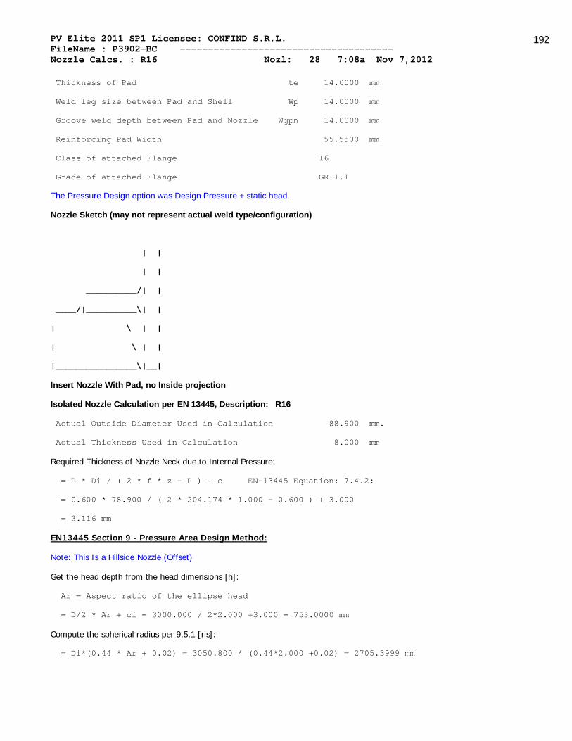
PV Elite 2011 SP1 Licensee: CONFIND S.R.L. FileName : P3902-BC -------------------------------------- Nozzle Calcs. : R16 Nozl: 28 7:08a Nov 7,2012
192
Thickness of Pad te 14.0000 mm
Weld leg size between Pad and Shell Wp 14.0000 mm
Groove weld depth between Pad and Nozzle Wgpn 14.0000 mm
Reinforcing Pad Width 55.5500 mm
Class of attached Flange 16
Grade of attached Flange GR 1.1
The Pressure Design option was Design Pressure + static head.
Nozzle Sketch (may not represent actual weld type/configuration)
| |
| |
__________/| |
____/|__________\| |
| \ | |
| \ | |
|________________\|__|
Insert Nozzle With Pad, no Inside projection
Isolated Nozzle Calculation per EN 13445, Description: R16
Actual Outside Diameter Used in Calculation 88.900 mm.
Actual Thickness Used in Calculation 8.000 mm
Required Thickness of Nozzle Neck due to Internal Pressure:
= P * Di / ( 2 * f * z - P ) + c EN-13445 Equation: 7.4.2:
= 0.600 * 78.900 / ( 2 * 204.174 * 1.000 - 0.600 ) + 3.000
= 3.116 mm
EN13445 Section 9 - Pressure Area Design Method:
Note: This Is a Hillside Nozzle (Offset)
Get the head depth from the head dimensions [h]:
Ar = Aspect ratio of the ellipse head
= D/2 * Ar + ci = 3000.000 / 2*2.000 +3.000 = 753.0000 mm
Compute the spherical radius per 9.5.1 [ris]:
= Di*(0.44 * Ar + 0.02) = 3050.800 * (0.44*2.000 +0.02) = 2705.3999 mm

PV Elite 2011 SP1 Licensee: CONFIND S.R.L. FileName : P3902-BC -------------------------------------- Nozzle Calcs. : R16 Nozl: 28 7:08a Nov 7,2012
193
Credit Distance Along the Shell per 9.5.1 [Iso]:
= Sqrt((2*ris+eas)*eas) = Sqrt(2*2705.400 + 11.000 ) * 11.000 )
= 244.2126 mm
Credit Distance Along the Nozzle outside per 9.5.7.1 [Ibo]:
= min( sqrt( ( de - eab )*eab ), ho )
= min( sqrt((88.9000 - 5.0000 )*5.0000 , 167.0000 )
= 20.4817 mm
Credit Distance Along the Nozzle per inside 9.5.7.1 [Ibi]:
= Min(hi, 0.50 * Ibo) = Min(0.000 , 0.50 * 20.482 ) = 0.0000 mm
Mean radius of Head per Figure 9.4-10 [rm]:
= ris + eas / 2 = 2705.400 + 11.000 / 2 = 2710.8999 mm
Angle subtending 'a' in figure 9.5-3 [Alpha]:
= asin( Offset / Rm ) - asin( ( Offset - 0.5 * dib) / Rm )
= asin(1100.000 /2710.900 )-asin((1100.000 -0.5*88.900 )/2710.900 )
= 0.0179 radians
The distance as depicted in figure 9.5-3 [a]:
= Alpha * rms = 0.018 * 2710.900 = 48.4440 mm
Angle between nozzle centreling and head centrline [Beta]:
= Asin(Offset / rms) = Asin(1100.000 )/2710.900 ) = 0.4178 radians
Small triangular area fig 9.5-3 [Ap_psi]:
= 0.5*dib²*tab(Beta) = 0.5*78.900²*Tan(0.418 ) = 1381.8744 mm²
Pressure area inside shell/head per 9.5-56 [Aps]:
= 0.5 * ris² * ( Iso + a ) / ( 0.5 * eas + ris ) + a * ( eas + eap )
= 0.5*2705.400 **2*(244.213 +48.444 )/(0.5*11.000 +2705.400 ) +
48.444 *(11.000 +14.000 ) = 396.2846 x 10^3 mm²
Area in the nozzle [Apb]:
= min(ho, Ibo)*dib*0.5 = min(167.000 , 20.482 )*78.900 *0.5
= 808.0030 mm²
Afs = Iso * eas = 244.213 * 11.000 = 2686.3389 mm²
Afb = Ibo * eab + Ibi * Max(eab - cn + cnext, 0 )
= 20.482 * 5.000 + 0.000 * 0.000
= 102.4085 mm²
Afp = Ip * eap = 55.550 * 14.000 = 777.7001 mm²

PV Elite 2011 SP1 Licensee: CONFIND S.R.L. FileName : P3902-BC -------------------------------------- Nozzle Calcs. : R16 Nozl: 28 7:08a Nov 7,2012
194
Afw = 196.0000 mm²
Calculation per paragraph 9.5.2.1.1 [fob, fop]:
fob = Min(fs, fb) = Min(204.174 , 204.174 ) = 204.174 MPa
fop = Min(fs, fp) = Min(204.174 , 204.174 ) = 204.174 MPa
Pressure Area Check Term per paragraph 9.5.2.1.1 [Pa]:
= (Afs+Afw)*(fs-0.5P)+Afp*(Min(fs,fp) - 0.5P) + Afb(Min(fs,fb) - 0.5P)
= (2686.339 + 196.000 ) * (204.174 - 0.5 * 0.600 ) +
(777.700 * (Min(204.174 , 204.174 ) - 0.50 * 0.600 ) +
(102.408 * (Min(204.174 , 204.174 ) - 0.50 * 0.600 )
= 766.9993 x 10^3 N
Stress Area term per paragraph 9.5.2.1.1 [Pa]:
= P * ( Aps + Apb + .5 * APpsi )
= 0.600 * ( 396284.594 + 808.003 + 0.5*0.000 ) = 238.6498 x 10^3 N
Since Pa >= Fa, Code Requirements are satisfied.
The Drop for this Nozzle is : 20.2125 mm
The Cut Length for this Nozzle is, Drop + Ho + H + T : 202.5221 mm
For possible nozzle interference - See Nozzle Summary
PV Elite is a trademark of Intergraph CADWorx & Analysis Solutions, Inc. 2011

PV Elite 2011 SP1 Licensee: CONFIND S.R.L. FileName : P3902-BC -------------------------------------- Nozzle Calcs. : R14 Nozl: 29 7:08a Nov 7,2012
195
INPUT VALUES, Nozzle Description: R14 From : 30
Pressure for Reinforcement Calculations P 0.6000 MPa
Temperature for Internal Pressure Temp 60 C
Shell Material P355NH
Shell Allowable Stress at Temperature S 204.17 MPa
Shell Allowable Stress At Ambient Sa 204.17 MPa
Inside Diameter of Elliptical Head D 3000.00 mm
Aspect Ratio of Elliptical Head Ar 2.00
Head Finished (Minimum) Thickness t 14.0000 mm
Head Internal Corrosion Allowance c 3.0000 mm
Head External Corrosion Allowance co 0.0000 mm
Distance from Head Centerline L1 1086.0000 mm
Type of Element Connected to the Shell : Nozzle
Nozzle Material P355NH
Allowable Stress at Temperature Sn 204.17 MPa
Allowable Stress At Ambient Sna 204.17 MPa
Diameter Basis (for tr calc only) OD
Layout Angle 158.00 deg
Diameter 88.9000 mm.
Size and Thickness Basis Actual
Actual Thickness tn 8.0000 mm
Flange Material P285QH
Flange Type Weld Neck Flange
Corrosion Allowance can 3.0000 mm
Outside Projection ho 167.0000 mm
Weld leg size between Nozzle and Pad/Shell Wo 14.0000 mm
Groove weld depth between Nozzle and Vessel Wgnv 14.0000 mm
Inside Projection h 0.0000 mm
Weld leg size, Inside Element to Shell Wi 0.0000 mm
Pad Material P355NH
Pad Allowable Stress at Temperature Sp 204.17 MPa
Pad Allowable Stress At Ambient Spa 204.17 MPa
Diameter of Pad along vessel surface Dp 200.0000 mm

PV Elite 2011 SP1 Licensee: CONFIND S.R.L. FileName : P3902-BC -------------------------------------- Nozzle Calcs. : R14 Nozl: 29 7:08a Nov 7,2012
196
Thickness of Pad te 14.0000 mm
Weld leg size between Pad and Shell Wp 14.0000 mm
Groove weld depth between Pad and Nozzle Wgpn 14.0000 mm
Reinforcing Pad Width 55.5500 mm
Class of attached Flange 16
Grade of attached Flange GR 1.1
The Pressure Design option was Design Pressure + static head.
Nozzle Sketch (may not represent actual weld type/configuration)
| |
| |
__________/| |
____/|__________\| |
| \ | |
| \ | |
|________________\|__|
Insert Nozzle With Pad, no Inside projection
Isolated Nozzle Calculation per EN 13445, Description: R14
Actual Outside Diameter Used in Calculation 88.900 mm.
Actual Thickness Used in Calculation 8.000 mm
Required Thickness of Nozzle Neck due to Internal Pressure:
= P * Di / ( 2 * f * z - P ) + c EN-13445 Equation: 7.4.2:
= 0.600 * 78.900 / ( 2 * 204.174 * 1.000 - 0.600 ) + 3.000
= 3.116 mm
EN13445 Section 9 - Pressure Area Design Method:
Note: This Is a Hillside Nozzle (Offset)
Get the head depth from the head dimensions [h]:
Ar = Aspect ratio of the ellipse head
= D/2 * Ar + ci = 3000.000 / 2*2.000 +3.000 = 753.0000 mm
Compute the spherical radius per 9.5.1 [ris]:
= Di*(0.44 * Ar + 0.02) = 3050.800 * (0.44*2.000 +0.02) = 2705.3999 mm

PV Elite 2011 SP1 Licensee: CONFIND S.R.L. FileName : P3902-BC -------------------------------------- Nozzle Calcs. : R14 Nozl: 29 7:08a Nov 7,2012
197
Credit Distance Along the Shell per 9.5.1 [Iso]:
= Sqrt((2*ris+eas)*eas) = Sqrt(2*2705.400 + 11.000 ) * 11.000 )
= 244.2126 mm
Credit Distance Along the Nozzle outside per 9.5.7.1 [Ibo]:
= min( sqrt( ( de - eab )*eab ), ho )
= min( sqrt((88.9000 - 5.0000 )*5.0000 , 167.0000 )
= 20.4817 mm
Credit Distance Along the Nozzle per inside 9.5.7.1 [Ibi]:
= Min(hi, 0.50 * Ibo) = Min(0.000 , 0.50 * 20.482 ) = 0.0000 mm
Mean radius of Head per Figure 9.4-10 [rm]:
= ris + eas / 2 = 2705.400 + 11.000 / 2 = 2710.8999 mm
Angle subtending 'a' in figure 9.5-3 [Alpha]:
= asin( Offset / Rm ) - asin( ( Offset - 0.5 * dib) / Rm )
= asin(1086.000 /2710.900 )-asin((1086.000 -0.5*88.900 )/2710.900 )
= 0.0178 radians
The distance as depicted in figure 9.5-3 [a]:
= Alpha * rms = 0.018 * 2710.900 = 48.3271 mm
Angle between nozzle centreling and head centrline [Beta]:
= Asin(Offset / rms) = Asin(1086.000 )/2710.900 ) = 0.4122 radians
Small triangular area fig 9.5-3 [Ap_psi]:
= 0.5*dib²*tab(Beta) = 0.5*78.900²*Tan(0.412 ) = 1360.8990 mm²
Pressure area inside shell/head per 9.5-56 [Aps]:
= 0.5 * ris² * ( Iso + a ) / ( 0.5 * eas + ris ) + a * ( eas + eap )
= 0.5*2705.400 **2*(244.213 +48.327 )/(0.5*11.000 +2705.400 ) +
48.327 *(11.000 +14.000 ) = 396.1237 x 10^3 mm²
Area in the nozzle [Apb]:
= min(ho, Ibo)*dib*0.5 = min(167.000 , 20.482 )*78.900 *0.5
= 808.0030 mm²
Afs = Iso * eas = 244.213 * 11.000 = 2686.3389 mm²
Afb = Ibo * eab + Ibi * Max(eab - cn + cnext, 0 )
= 20.482 * 5.000 + 0.000 * 0.000
= 102.4085 mm²
Afp = Ip * eap = 55.550 * 14.000 = 777.7001 mm²

PV Elite 2011 SP1 Licensee: CONFIND S.R.L. FileName : P3902-BC -------------------------------------- Nozzle Calcs. : R14 Nozl: 29 7:08a Nov 7,2012
198
Afw = 196.0000 mm²
Calculation per paragraph 9.5.2.1.1 [fob, fop]:
fob = Min(fs, fb) = Min(204.174 , 204.174 ) = 204.174 MPa
fop = Min(fs, fp) = Min(204.174 , 204.174 ) = 204.174 MPa
Pressure Area Check Term per paragraph 9.5.2.1.1 [Pa]:
= (Afs+Afw)*(fs-0.5P)+Afp*(Min(fs,fp) - 0.5P) + Afb(Min(fs,fb) - 0.5P)
= (2686.339 + 196.000 ) * (204.174 - 0.5 * 0.600 ) +
(777.700 * (Min(204.174 , 204.174 ) - 0.50 * 0.600 ) +
(102.408 * (Min(204.174 , 204.174 ) - 0.50 * 0.600 )
= 766.9993 x 10^3 N
Stress Area term per paragraph 9.5.2.1.1 [Pa]:
= P * ( Aps + Apb + .5 * APpsi )
= 0.600 * ( 396123.750 + 808.003 + 0.5*0.000 ) = 238.5471 x 10^3 N
Since Pa >= Fa, Code Requirements are satisfied.
The Drop for this Nozzle is : 19.9094 mm
The Cut Length for this Nozzle is, Drop + Ho + H + T : 202.1812 mm
For possible nozzle interference - See Nozzle Summary
V Elite is a trademark of Intergraph CADWorx & Analysis Solutions, Inc. 2011

PV Elite 2011 SP1 Licensee: CONFIND S.R.L. FileName : P3902-BC -------------------------------------- Nozzle Calcs. : R13 Nozl: 30 7:08a Nov 7,2012
199
INPUT VALUES, Nozzle Description: R13 From : 30
Pressure for Reinforcement Calculations P 0.6000 MPa
Temperature for Internal Pressure Temp 60 C
Shell Material P355NH
Shell Allowable Stress at Temperature S 204.17 MPa
Shell Allowable Stress At Ambient Sa 204.17 MPa
Inside Diameter of Elliptical Head D 3000.00 mm
Aspect Ratio of Elliptical Head Ar 2.00
Head Finished (Minimum) Thickness t 14.0000 mm
Head Internal Corrosion Allowance c 3.0000 mm
Head External Corrosion Allowance co 0.0000 mm
Distance from Head Centerline L1 1011.0000 mm
Type of Element Connected to the Shell : Nozzle
Nozzle Material P285QH
Allowable Stress at Temperature Sn 162.51 MPa
Allowable Stress At Ambient Sna 162.51 MPa
Diameter Basis (for tr calc only) OD
Layout Angle 81.00 deg
Diameter 88.9000 mm.
Size and Thickness Basis Actual
Actual Thickness tn 8.0000 mm
Flange Material P285QH
Flange Type Weld Neck Flange
Corrosion Allowance can 3.0000 mm
Outside Projection ho 167.0000 mm
Weld leg size between Nozzle and Pad/Shell Wo 14.0000 mm
Groove weld depth between Nozzle and Vessel Wgnv 14.0000 mm
Inside Projection h 0.0000 mm
Weld leg size, Inside Element to Shell Wi 0.0000 mm
Pad Material P235GH
Pad Allowable Stress at Temperature Sp 135.21 MPa
Pad Allowable Stress At Ambient Spa 150.01 MPa
Diameter of Pad along vessel surface Dp 0.0000 mm

PV Elite 2011 SP1 Licensee: CONFIND S.R.L. FileName : P3902-BC -------------------------------------- Nozzle Calcs. : R13 Nozl: 30 7:08a Nov 7,2012
200
Thickness of Pad te 0.0000 mm
Weld leg size between Pad and Shell Wp 0.0000 mm
Groove weld depth between Pad and Nozzle Wgpn 0.0000 mm
Reinforcing Pad Width -44.4500 mm
Class of attached Flange 16
Grade of attached Flange GR 1.1
The Pressure Design option was Design Pressure + static head.
Nozzle Sketch (may not represent actual weld type/configuration)
| |
| |
__________/| |
____/|__________\| |
| \ | |
| \ | |
|________________\|__|
Insert Nozzle With Pad, no Inside projection
Isolated Nozzle Calculation per EN 13445, Description: R13
Actual Outside Diameter Used in Calculation 88.900 mm.
Actual Thickness Used in Calculation 8.000 mm
Required Thickness of Nozzle Neck due to Internal Pressure:
= P * Di / ( 2 * f * z - P ) + c EN-13445 Equation: 7.4.2:
= 0.600 * 78.900 / ( 2 * 162.506 * 1.000 - 0.600 ) + 3.000
= 3.146 mm
EN13445 Section 9 - Pressure Area Design Method:
Note: This Is a Hillside Nozzle (Offset)
Get the head depth from the head dimensions [h]:
Ar = Aspect ratio of the ellipse head
= D/2 * Ar + ci = 3000.000 / 2*2.000 +3.000 = 753.0000 mm
Compute the spherical radius per 9.5.1 [ris]:
= Di*(0.44 * Ar + 0.02) = 3050.800 * (0.44*2.000 +0.02) = 2705.3999 mm
Credit Distance Along the Shell per 9.5.1 [Iso]:
= Sqrt((2*ris+eas)*eas) = Sqrt(2*2705.400 + 11.000 ) * 11.000 )
= 244.2126 mm

PV Elite 2011 SP1 Licensee: CONFIND S.R.L. FileName : P3902-BC -------------------------------------- Nozzle Calcs. : R13 Nozl: 30 7:08a Nov 7,2012
201
Credit Distance Along the Nozzle outside per 9.5.7.1 [Ibo]:
= min( sqrt( ( de - eab )*eab ), ho )
= min( sqrt((88.9000 - 5.0000 )*5.0000 , 167.0000 )
= 20.4817 mm
Credit Distance Along the Nozzle per inside 9.5.7.1 [Ibi]:
= Min(hi, 0.50 * Ibo) = Min(0.000 , 0.50 * 20.482 ) = 0.0000 mm
Mean radius of Head per Figure 9.4-10 [rm]:
= ris + eas / 2 = 2705.400 + 11.000 / 2 = 2710.8999 mm
Angle subtending 'a' in figure 9.5-3 [Alpha]:
= asin( Offset / Rm ) - asin( ( Offset - 0.5 * dib) / Rm )
= asin(1011.000 /2710.900 )-asin((1011.000 -0.5*88.900 )/2710.900 )
= 0.0176 radians
The distance as depicted in figure 9.5-3 [a]:
= Alpha * rms = 0.018 * 2710.900 = 47.7396 mm
Angle between nozzle centreling and head centrline [Beta]:
= Asin(Offset / rms) = Asin(1011.000 )/2710.900 ) = 0.3822 radians
Small triangular area fig 9.5-3 [Ap_psi]:
= 0.5*dib²*tab(Beta) = 0.5*78.900²*Tan(0.382 ) = 1251.0686 mm²
Pressure area inside shell/head per 9.5-56 [Aps]:
= 0.5 * ris² * ( Iso + a ) / ( 0.5 * eas + ris ) + a * ( eas + eap )
= 0.5*2705.400 **2*(244.213 +47.740 )/(0.5*11.000 +2705.400 ) +
47.740 *(11.000 +0.000 ) = 394.6477 x 10^3 mm²
Area in the nozzle [Apb]:
= min(ho, Ibo)*dib*0.5 = min(167.000 , 20.482 )*78.900 *0.5
= 808.0030 mm²
Afs = Iso * eas = 244.213 * 11.000 = 2686.3389 mm²
Afb = Ibo * eab + Ibi * Max(eab - cn + cnext, 0 )
= 20.482 * 5.000 + 0.000 * 0.000
= 102.4085 mm²
Afp = Ip * eap = 0.000 * 0.000 = 0.0000 mm²
Afw = 98.0000 mm²
Note: There is No Reinforcement Pad
Calculation per paragraph 9.5.2.1.1 [fob, fop]:

PV Elite 2011 SP1 Licensee: CONFIND S.R.L. FileName : P3902-BC -------------------------------------- Nozzle Calcs. : R13 Nozl: 30 7:08a Nov 7,2012
202
fob = Min(fs, fb) = Min(204.174 , 162.506 ) = 162.506 MPa
fop = Min(fs, fp) = Min(204.174 , 135.206 ) = 135.206 MPa
Pressure Area Check Term per paragraph 9.5.2.1.1 [Pa]:
= (Afs+Afw)*(fs-0.5P)+Afp*(Min(fs,fp) - 0.5P) + Afb(Min(fs,fb) - 0.5P)
= (2686.339 + 98.000 ) * (204.174 - 0.5 * 0.600 ) +
(0.000 * (Min(204.174 , 135.206 ) - 0.50 * 0.600 ) +
(102.408 * (Min(204.174 , 162.506 ) - 0.50 * 0.600 )
= 584.2154 x 10^3 N
Stress Area term per paragraph 9.5.2.1.1 [Pa]:
= P * ( Aps + Apb + .5 * APpsi )
= 0.600 * ( 394647.656 + 808.003 + 0.5*0.000 ) = 237.6285 x 10^3 N
Since Pa >= Fa, Code Requirements are satisfied.
The Drop for this Nozzle is : 18.3233 mm
The Cut Length for this Nozzle is, Drop + Ho + H + T : 200.4051 mm
For possible nozzle interference - See Nozzle Summary
PV Elite is a trademark of Intergraph CADWorx & Analysis Solutions, Inc. 2011

PV Elite 2011 SP1 Licensee: CONFIND S.R.L. FileName : P3902-BC -------------------------------------- Nozzle Schedule : Step: 42 7:08a Nov 7,2012
203
Nozzle Schedule:
Nominal Flange Noz. Wall Re-Pad Cut
Description Size Sch/Type O/Dia Thk ODia Thick Length
mm Cls mm mm mm mm mm
------------------------------------------------------------------------------
M1 51 - None 51.000 12.500 - - 80
R17b 51 40 WNF 51.000 12.500 - - 74
R17d 51 40 WNF 51.000 12.500 - - 62
R17a 51 40 WNF 51.000 12.500 - - 174
R11 88 16 WNF 88.900 8.000 200.00 14.00 164
R9 88 16 WNF 88.900 8.000 200.00 14.00 157
R18a 88 16 WNF 88.900 8.000 200.00 14.00 170
R10 88 16 WNF 88.900 8.000 200.00 14.00 242
R12 88 16 WNF 88.900 8.000 200.00 14.00 169
R20 88 16 WNF 88.900 8.000 200.00 14.00 164
R15 88 16 WNF 88.900 8.000 200.00 14.00 189
R18b 88 16 WNF 88.900 8.000 200.00 14.00 197
R16 88 16 WNF 88.900 8.000 200.00 14.00 202
R14 88 16 WNF 88.900 8.000 200.00 14.00 202
R13 88 16 WNF 88.900 8.000 - - 200
R3 114 16 WNF 114.300 10.000 310.00 14.00 394
R8 168 16 WNF 168.300 10.000 310.00 14.00 161
R2 168 16 WNF 168.300 10.000 310.00 14.00 161
R7c 168 40 WNF 168.300 10.000 310.00 14.00 116
R7b 168 40 WNF 168.300 10.000 310.00 14.00 116
R7a 168 40 WNF 168.300 10.000 310.00 14.00 116
R4 168 16 WNF 168.300 10.000 310.00 14.00 161
R1 219 16 WNF 219.100 10.000 310.00 14.00 836
R6 219 16 WNF 219.100 10.000 400.00 14.00 163
R5 219 16 WNF 219.100 10.000 400.00 14.00 158
R19 219 16 SlipOn239.100 10.000 310.00 14.00 307
GV1a 508 10 SlipOn508.000 10.000 800.00 14.00 275
GV2a 508 10 SlipOn508.000 10.000 800.00 14.00 285

PV Elite 2011 SP1 Licensee: CONFIND S.R.L. FileName : P3902-BC -------------------------------------- Nozzle Schedule : Step: 42 7:08a Nov 7,2012
204
GV2b 508 10 SlipOn508.000 10.000 800.00 14.00 285
GV1b 508 10 SlipOn528.000 10.000 800.00 14.00 276
Note on the Cut Length Calculation:
The Cut Length is the Outside Projection + Inside Projection + Drop +
In Plane Shell Thickness. This value does not include weld gaps,
nor does it account for shrinkage.
Please Note: In the case of Oblique Nozzles, the Outside Diameter must
be increased. The Re-Pad WIDTH around the nozzle is calculated as follows:
Width of Pad = (Pad Outside Dia. (per above) - Nozzle Outside Dia.)/2
Nozzle Material and Weld Fillet Leg Size Details:
Shl Grve Noz Shl/Pad Pad OD Pad Grve Inside
Nozzle Material Weld Weld Weld Weld Weld
mm mm mm mm mm
------------------------------------------------------------------------------
M1 P285QH 14.000 14.000 - - -
R17b P285QH 14.000 14.000 - - -
R17d P285QH 14.000 14.000 - - -
R17a P285QH 14.000 14.000 - - -
R11 P355NH 14.000 14.000 14.000 14.000 -
R9 P355NH 14.000 14.000 14.000 14.000 -
R18a P355NH 14.000 14.000 14.000 14.000 -
R10 P355NH 14.000 14.000 14.000 14.000 -
R12 P355NH 14.000 14.000 14.000 14.000 -
R20 P285QH 14.000 14.000 14.000 14.000 -
R15 P355NH 14.000 14.000 14.000 14.000 -
R18b P355NH 14.000 14.000 14.000 14.000 -
R16 P355NH 14.000 14.000 14.000 14.000 -
R14 P355NH 14.000 14.000 14.000 14.000 -
R13 P285QH 14.000 14.000 - - -
R3 P355NH 14.000 14.000 14.000 14.000 -

PV Elite 2011 SP1 Licensee: CONFIND S.R.L. FileName : P3902-BC -------------------------------------- Nozzle Schedule : Step: 42 7:08a Nov 7,2012
205
R8 P355NH 14.000 14.000 14.000 14.000 -
R2 P355NH 14.000 14.000 14.000 14.000 -
R7c P355NH 14.000 14.000 14.000 14.000 -
R7b P355NH 14.000 14.000 14.000 14.000 -
R7a P355NH 14.000 14.000 14.000 14.000 -
R4 P355NH 14.000 14.000 14.000 14.000 -
R1 P355NH 14.000 14.000 14.000 14.000 -
R6 P355NH 14.000 14.000 14.000 14.000 -
R5 P355NH 14.000 14.000 14.000 14.000 -
R19 P355NH 14.000 14.000 14.000 14.000 -
GV1a P355NH 14.000 14.000 14.000 14.000 -
GV2a P355NH 14.000 14.000 6.000 10.000 -
GV2b P355NH 14.000 14.000 6.000 10.000 -
GV1b P355NH 14.000 14.000 14.000 14.000 -
Note: The Outside projections below do not include the flange thickness.
Nozzle Miscellaneous Data:
Elevation/Distance Layout Projection Installed In
Nozzle From Datum Angle Outside Inside Component
mm deg. mm mm
----------------------------------------------------------------------------
M1 3910.000 0.00 66.00 0.00 VIROLA
R17b 8700.001 180.00 60.00 0.00 VIROLA
R17d 10290.001 -161.00 38.00 0.00 VIROLA
R17a 8700.001 283.00 132.00 0.00 VIROLA
R11 9150.000 90.00 150.00 0.00 VIROLA
R9 8850.000 95.69 138.00 0.00 VIROLA
R18a 9000.000 113.35 135.00 0.00 VIROLA
R10 9150.000 142.43 157.00 0.00 VIROLA
R12 8850.000 131.34 109.00 0.00 VIROLA
R20 8970.000 0.00 150.00 0.00 VIROLA
R15 90.00 163.00 0.00 FUND ELIPSOI

PV Elite 2011 SP1 Licensee: CONFIND S.R.L. FileName : P3902-BC -------------------------------------- Nozzle Schedule : Step: 42 7:08a Nov 7,2012
206
R18b 126.00 167.00 0.00 FUND ELIPSOI
R16 141.00 167.00 0.00 FUND ELIPSOI
R14 158.00 167.00 0.00 FUND ELIPSOI
R13 81.00 167.00 0.00 FUND ELIPSOI
R3 180.00 250.00 100.00 FUND ELIPSOI
R8 6990.000 0.00 145.00 0.00 VIROLA
R2 9270.001 0.00 145.00 0.00 VIROLA
R7c 300.000 180.00 100.00 0.00 VIROLA
R7b 2750.000 180.00 100.00 0.00 VIROLA
R7a 7700.000 180.00 100.00 0.00 VIROLA
R4 10150.001 180.00 145.00 0.00 VIROLA
R1 0.00 280.00 490.00 FUND ELIPSOI
R6 10000.001 0.00 145.00 0.00 VIROLA
R5 8960.000 180.00 140.00 0.00 VIROLA
R19 180.00 250.00 0.00 FUND ELIPSOI
GV1a 0.00 250.00 0.00 FUND ELIPSOI
GV2a 550.000 0.00 250.00 0.00 VIROLA
GV2b 8000.000 0.00 250.00 0.00 VIROLA
GV1b 0.00 250.00 0.00 FUND ELIPSOI
PV Elite is a trademark of Intergraph CADWorx & Analysis Solutions, Inc. 2011

PV Elite 2011 SP1 Licensee: CONFIND S.R.L. FileName : P3902-BC -------------------------------------- Nozzle Summary : Step: 43 7:08a Nov 7,2012
207
Nozzle Calculation Summary:
Per EN 13445 Section 9:
Description Pressure Area Result
---------------------------------------------------------------------------
GV1a Pressure Area Passed
R1 Pressure Area Passed
R3 Pressure Area Passed
GV2a Pressure Area Passed
GV2b Pressure Area Passed
M1 Pressure Area Passed
R8 Pressure Area Passed
R2 Pressure Area Passed
R6 Pressure Area Passed
R7c Pressure Area Passed
R7b Pressure Area Passed
R7a Pressure Area Passed
R5 Pressure Area Passed
R4 Pressure Area Passed
R17b Pressure Area Passed
R17d Pressure Area Passed
R11 Pressure Area Passed
R9 Pressure Area Passed
R18a Pressure Area Passed
R10 Pressure Area Passed
R12 Pressure Area Passed
R17a Pressure Area Passed
R20 Pressure Area Passed
GV1b Pressure Area Passed
R19 Pressure Area Passed
R15 Pressure Area Passed
R18b Pressure Area Passed
R16 Pressure Area Passed
R14 Pressure Area Passed
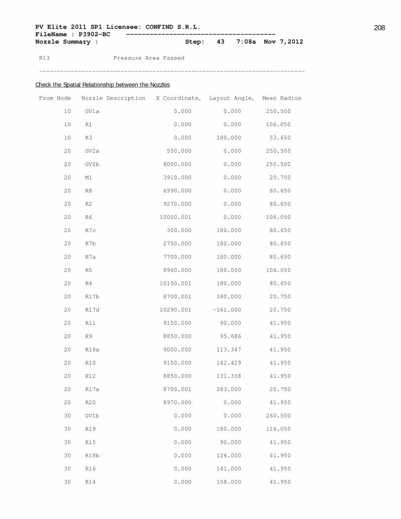
PV Elite 2011 SP1 Licensee: CONFIND S.R.L. FileName : P3902-BC -------------------------------------- Nozzle Summary : Step: 43 7:08a Nov 7,2012
208
R13 Pressure Area Passed
---------------------------------------------------------------------------
Check the Spatial Relationship between the Nozzles
From Node Nozzle Description X Coordinate, Layout Angle, Mean Radius
10 GV1a 0.000 0.000 250.500
10 R1 0.000 0.000 106.050
10 R3 0.000 180.000 53.650
20 GV2a 550.000 0.000 250.500
20 GV2b 8000.000 0.000 250.500
20 M1 3910.000 0.000 20.750
20 R8 6990.000 0.000 80.650
20 R2 9270.000 0.000 80.650
20 R6 10000.001 0.000 106.050
20 R7c 300.000 180.000 80.650
20 R7b 2750.000 180.000 80.650
20 R7a 7700.000 180.000 80.650
20 R5 8960.000 180.000 106.050
20 R4 10150.001 180.000 80.650
20 R17b 8700.001 180.000 20.750
20 R17d 10290.001 -161.000 20.750
20 R11 9150.000 90.000 41.950
20 R9 8850.000 95.686 41.950
20 R18a 9000.000 113.347 41.950
20 R10 9150.000 142.429 41.950
20 R12 8850.000 131.338 41.950
20 R17a 8700.001 283.000 20.750
20 R20 8970.000 0.000 41.950
30 GV1b 0.000 0.000 260.500
30 R19 0.000 180.000 116.050
30 R15 0.000 90.000 41.950
30 R18b 0.000 126.000 41.950
30 R16 0.000 141.000 41.950
30 R14 0.000 158.000 41.950

PV Elite 2011 SP1 Licensee: CONFIND S.R.L. FileName : P3902-BC -------------------------------------- Nozzle Summary : Step: 43 7:08a Nov 7,2012
209
30 R13 0.000 81.000 41.950
If any interferences/violations are found, they will be noted below.
Note: Items not derived explicitly will be found in the individual nozzle
calculation. These items include such values as Afls etc.
Nozzles R2 and R20 are a Group per EN 13445 para 9.6.4
------------------------------------------------------
The Nozzles are Installed In a Cylinder
ris = (ris1 + ris2)/2 = (1503.000 + 1503.000 ) / 2 = 1503.0000 mm
Lb = 300.0003 mm (= Inside center to center distance)
a1 = deb1/2 = 84.1500 and a2 = deb2/2 = 44.4500 mm
k = 2 - (Lb + a1 + a2)/(Iso1 + Iso2)
= 2 - (300.000 + 84.150 + 44.450 )/(182.173 + 182.173 ) = 0.8236
Lb1 = Lb + a1 + a2 + k * (Iso1 + Iso2)
= 300.000 + 84.150 + 44.450 + 0.824 * (182.173 + 182.173 )
= 728.6920 mm
psi = atan(ris * abs(Angle2 - Angle1) / abs( y2 - y1 )
= atan(1503.000 * abs(0.000 - 0.000 ) / abs( 9220.001 - 8920.000 )
= 0.0000 Deg
Apls = 0.5*ris²*Lb * (1 + cos(psi))/(ris+0.5 * eas * sin(psi))
= 0.5*1503.00²*300.00 *(1+cos(0.00 ))/(1503.00 +0.5*11.00 * sin(0.
= 450.9004 x 10^3 mm²
Metal area
Afb1 = 235.2146 , Afb2 = 102.4085 mm²
Afls = eas * (Lb - a1 - a2)
= 11.000 * (300.000 - 84.150 - 44.450 ) = 1885.4032 mm²
Afw = Afw1 + Afw2 = 196.000 + 196.000 = 392.0000 mm²
APsil = 0.0000 and APpsi2 = 0.0000 mm²
f1 = (Afls + Afw ) * (fs - 0.5 * p)
+ Afb1 * (fob1 - 0.5 * p)
+ Afb2 * (fob2 - 0.5 * p)
+ Afp1 * (fop1 - 0.5 * p)
+ Afp2 * (fop2 - 0.5 * p)
= (1885.403 + 392.000 ) * (204.174 - 0.5 * 0.600 )

PV Elite 2011 SP1 Licensee: CONFIND S.R.L. FileName : P3902-BC -------------------------------------- Nozzle Summary : Step: 43 7:08a Nov 7,2012
210
+ 235.215 * (204.174 - 0.5 * 0.600 )
+ 102.408 * (162.506 - 0.5 * 0.600 )
+ 991.900 * (204.174 - 0.5 * 0.600 )
+ 777.700 * (204.174 - 0.5 * 0.600 )
= 889.5678 x 10^3 N
f2 = P * ( Apls + Apb1 + 0.5 * APpsi1 + Apb2 + 0.5 * APpsi2)
= 0.600 *(450900.438+2592.401 + .5*0.000 +808.003 +0.50* 0.000 )
= 272.5573 x 10^3 N
Because f1 > f2: The Group Is Adequately Reinforced
Nozzles R5 and R17b are a Group per EN 13445 para 9.6.4
-------------------------------------------------------
The Nozzles are Installed In a Cylinder
ris = (ris1 + ris2)/2 = (1503.000 + 1503.000 ) / 2 = 1503.0000 mm
Lb = 259.9996 mm (= Inside center to center distance)
a1 = deb1/2 = 109.5500 and a2 = deb2/2 = 25.5000 mm
k = 2 - (Lb + a1 + a2)/(Iso1 + Iso2)
= 2 - (260.000 + 109.550 + 25.500 )/(182.173 + 182.173 ) = 0.9157
Lb1 = Lb + a1 + a2 + k * (Iso1 + Iso2)
= 260.000 + 109.550 + 25.500 + 0.916 * (182.173 + 182.173 )
= 728.6920 mm
psi = atan(ris * abs(Angle2 - Angle1) / abs( y2 - y1 )
= atan(1503.000 * abs(180.000 - 180.000 ) / abs( 8910.000 - 8650.0
= 0.0000 Deg
Apls = 0.5*ris²*Lb * (1 + cos(psi))/(ris+0.5 * eas * sin(psi))
= 0.5*1503.00²*260.00 *(1+cos(0.00 ))/(1503.00 +0.5*11.00 * sin(0.
= 390.7794 x 10^3 mm²
Metal area
Afb1 = 269.7226 , Afb2 = 188.6294 mm²
Afls = eas * (Lb - a1 - a2)
= 11.000 * (260.000 - 109.550 - 25.500 ) = 1374.4460 mm²
Afw = Afw1 + Afw2 = 196.000 + 98.000 = 294.0000 mm²
APsil = 0.0000 and APpsi2 = 0.0000 mm²

PV Elite 2011 SP1 Licensee: CONFIND S.R.L. FileName : P3902-BC -------------------------------------- Nozzle Summary : Step: 43 7:08a Nov 7,2012
211
f1 = (Afls + Afw ) * (fs - 0.5 * p)
+ Afb1 * (fob1 - 0.5 * p)
+ Afb2 * (fob2 - 0.5 * p)
+ Afp1 * (fop1 - 0.5 * p)
+ Afp2 * (fop2 - 0.5 * p)
= (1374.446 + 294.000 ) * (204.174 - 0.5 * 0.600 )
+ 269.723 * (204.174 - 0.5 * 0.600 )
+ 188.629 * (162.506 - 0.5 * 0.600 )
+ 1266.300 * (204.174 - 0.5 * 0.600 )
+ 0.000 * (0.000 - 0.5 * 0.600 )
= 683.8460 x 10^3 N
f2 = P * ( Apls + Apb1 + 0.5 * APpsi1 + Apb2 + 0.5 * APpsi2)
= 0.600 *(390779.438+3951.437 + .5*0.000 +317.692 +0.50* 0.000 )
= 237.0090 x 10^3 N
Because f1 > f2: The Group Is Adequately Reinforced
Nozzles R11 and R9 are a Group per EN 13445 para 9.6.4
------------------------------------------------------
The Nozzles are Installed In a Cylinder
ris = (ris1 + ris2)/2 = (1503.000 + 1503.000 ) / 2 = 1503.0000 mm
Lb = 335.0330 mm (= Inside center to center distance)
a1 = deb1/2 = 44.4500 and a2 = deb2/2 = 44.4500 mm
k = 2 - (Lb + a1 + a2)/(Iso1 + Iso2)
= 2 - (335.033 + 44.450 + 44.450 )/(182.173 + 182.173 ) = 0.8365
Lb1 = Lb + a1 + a2 + k * (Iso1 + Iso2)
= 335.033 + 44.450 + 44.450 + 0.836 * (182.173 + 182.173 )
= 728.6920 mm
psi = atan(ris * abs(Angle2 - Angle1) / abs( y2 - y1 )
= atan(1503.000 * abs(90.000 - 95.686 ) / abs( 9100.000 - 8800.000
= 26.4357 Deg
Apls = 0.5*ris²*Lb * (1 + cos(psi))/(ris+0.5 * eas * sin(psi))
= 0.5*1503.00²*335.03 *(1+cos(26.44 ))/(1503.00 +0.5*11.00 * sin(2
= 476.4514 x 10^3 mm²

PV Elite 2011 SP1 Licensee: CONFIND S.R.L. FileName : P3902-BC -------------------------------------- Nozzle Summary : Step: 43 7:08a Nov 7,2012
212
Metal area
Afb1 = 102.4085 , Afb2 = 102.4085 mm²
Afls = eas * (Lb - a1 - a2)
= 11.000 * (335.033 - 44.450 - 44.450 ) = 2707.4636 mm²
Afw = Afw1 + Afw2 = 196.000 + 196.000 = 392.0000 mm²
APsil = 0.0000 and APpsi2 = 0.0000 mm²
f1 = (Afls + Afw ) * (fs - 0.5 * p)
+ Afb1 * (fob1 - 0.5 * p)
+ Afb2 * (fob2 - 0.5 * p)
+ Afp1 * (fop1 - 0.5 * p)
+ Afp2 * (fop2 - 0.5 * p)
= (2707.464 + 392.000 ) * (204.174 - 0.5 * 0.600 )
+ 102.408 * (204.174 - 0.5 * 0.600 )
+ 102.408 * (204.174 - 0.5 * 0.600 )
+ 777.700 * (204.174 - 0.5 * 0.600 )
+ 777.700 * (204.174 - 0.5 * 0.600 )
= 990.6776 x 10^3 N
f2 = P * ( Apls + Apb1 + 0.5 * APpsi1 + Apb2 + 0.5 * APpsi2)
= 0.600 *(476451.344+808.003 + .5*0.000 +808.003 +0.50* 0.000 )
= 286.8160 x 10^3 N
Because f1 > f2: The Group Is Adequately Reinforced
Nozzles R10 and R12 are a Group per EN 13445 para 9.6.4
-------------------------------------------------------
The Nozzles are Installed In a Cylinder
ris = (ris1 + ris2)/2 = (1503.000 + 1503.000 ) / 2 = 1503.0000 mm
Lb = 417.9088 mm (= Inside center to center distance)
a1 = deb1/2 = 44.4500 and a2 = deb2/2 = 44.4500 mm
k = 2 - (Lb + a1 + a2)/(Iso1 + Iso2)
= 2 - (417.909 + 44.450 + 44.450 )/(182.173 + 182.173 ) = 0.6090
Lb1 = Lb + a1 + a2 + k * (Iso1 + Iso2)
= 417.909 + 44.450 + 44.450 + 0.609 * (182.173 + 182.173 )
= 728.6920 mm
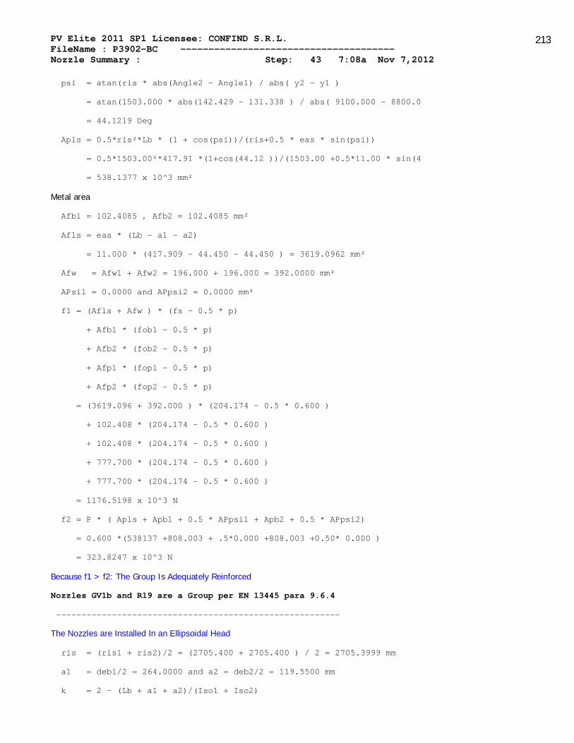
PV Elite 2011 SP1 Licensee: CONFIND S.R.L. FileName : P3902-BC -------------------------------------- Nozzle Summary : Step: 43 7:08a Nov 7,2012
213
psi = atan(ris * abs(Angle2 - Angle1) / abs( y2 - y1 )
= atan(1503.000 * abs(142.429 - 131.338 ) / abs( 9100.000 - 8800.0
= 44.1219 Deg
Apls = 0.5*ris²*Lb * (1 + cos(psi))/(ris+0.5 * eas * sin(psi))
= 0.5*1503.00²*417.91 *(1+cos(44.12 ))/(1503.00 +0.5*11.00 * sin(4
= 538.1377 x 10^3 mm²
Metal area
Afb1 = 102.4085 , Afb2 = 102.4085 mm²
Afls = eas * (Lb - a1 - a2)
= 11.000 * (417.909 - 44.450 - 44.450 ) = 3619.0962 mm²
Afw = Afw1 + Afw2 = 196.000 + 196.000 = 392.0000 mm²
APsil = 0.0000 and APpsi2 = 0.0000 mm²
f1 = (Afls + Afw ) * (fs - 0.5 * p)
+ Afb1 * (fob1 - 0.5 * p)
+ Afb2 * (fob2 - 0.5 * p)
+ Afp1 * (fop1 - 0.5 * p)
+ Afp2 * (fop2 - 0.5 * p)
= (3619.096 + 392.000 ) * (204.174 - 0.5 * 0.600 )
+ 102.408 * (204.174 - 0.5 * 0.600 )
+ 102.408 * (204.174 - 0.5 * 0.600 )
+ 777.700 * (204.174 - 0.5 * 0.600 )
+ 777.700 * (204.174 - 0.5 * 0.600 )
= 1176.5198 x 10^3 N
f2 = P * ( Apls + Apb1 + 0.5 * APpsi1 + Apb2 + 0.5 * APpsi2)
= 0.600 *(538137 +808.003 + .5*0.000 +808.003 +0.50* 0.000 )
= 323.8247 x 10^3 N
Because f1 > f2: The Group Is Adequately Reinforced
Nozzles GV1b and R19 are a Group per EN 13445 para 9.6.4
--------------------------------------------------------
The Nozzles are Installed In an Ellipsoidal Head
ris = (ris1 + ris2)/2 = (2705.400 + 2705.400 ) / 2 = 2705.3999 mm
a1 = deb1/2 = 264.0000 and a2 = deb2/2 = 119.5500 mm
k = 2 - (Lb + a1 + a2)/(Iso1 + Iso2)

PV Elite 2011 SP1 Licensee: CONFIND S.R.L. FileName : P3902-BC -------------------------------------- Nozzle Summary : Step: 43 7:08a Nov 7,2012
214
= 2 - (864.645 + 264.000 + 119.550 )/(244.213 + 244.213 ) = -0.555
Lb1 = Lb + a1 + a2 + k * (Iso1 + Iso2)
= 864.645 + 264.000 + 119.550 + -0.556 * (244.213 + 244.213 )
= 976.8505 mm
Lb = 864.6447 mm
Apls = 0.25 * (2 * ris)² * Lb / ( 2 * ris + eas )
= 0.25 * (2 * 2705.400 )² * 864.645 / ( 2 * 2705.400 + 0.433 )
= 1167.2319 x 10^3 mm²
Metal area
Afb1 = 422.7327 , Afb2 = 282.1529 mm²
Afls = eas * (Lb - a1 - a2)
= 11.000 * (864.645 - 264.000 - 119.550 ) = 5292.0420 mm²
Afw = Afw1 + Afw2 = 196.000 + 196.000 = 392.0000 mm²
APsil = 0.0000 and APpsi2 = 8365.6270 mm²
f1 = (Afls + Afw ) * (fs - 0.5 * p)
+ Afb1 * (fob1 - 0.5 * p)
+ Afb2 * (fob2 - 0.5 * p)
+ Afp1 * (fop1 - 0.5 * p)
+ Afp2 * (fop2 - 0.5 * p)
= (5292.042 + 392.000 ) * (204.174 - 0.5 * 0.600 )
+ 422.733 * (204.174 - 0.5 * 0.600 )
+ 282.153 * (204.174 - 0.5 * 0.600 )
+ 1904.000 * (204.174 - 0.5 * 0.600 )
+ 496.300 * (204.174 - 0.5 * 0.600 )
= 1791.7412 x 10^3 N
f2 = P * ( Apls + Apb1 + 0.5 * APpsi1 + Apb2 + 0.5 * APpsi2)
= 0.600 *(1167231 +18347.332 + .5*0.000 +5774.667 +0.50* 8365.627 )
= 717.2611 x 10^3 N
Because f1 > f2: The Group Is Adequately Reinforced
Nozzles GV1b and R15 are a Group per EN 13445 para 9.6.4
--------------------------------------------------------

PV Elite 2011 SP1 Licensee: CONFIND S.R.L. FileName : P3902-BC -------------------------------------- Nozzle Summary : Step: 43 7:08a Nov 7,2012
215
The Nozzles are Installed In an Ellipsoidal Head
ris = (ris1 + ris2)/2 = (2705.400 + 2705.400 ) / 2 = 2705.3999 mm
a1 = deb1/2 = 264.0000 and a2 = deb2/2 = 44.4500 mm
k = 2 - (Lb + a1 + a2)/(Iso1 + Iso2)
= 2 - (708.056 + 264.000 + 44.450 )/(244.213 + 244.213 ) = -0.0812
Lb1 = Lb + a1 + a2 + k * (Iso1 + Iso2)
= 708.056 + 264.000 + 44.450 + -0.081 * (244.213 + 244.213 )
= 976.8505 mm
Lb = 708.0556 mm
Apls = 0.25 * (2 * ris)² * Lb / ( 2 * ris + eas )
= 0.25 * (2 * 2705.400 )² * 708.056 / ( 2 * 2705.400 + 0.433 )
= 955.8436 x 10^3 mm²
Metal area
Afb1 = 422.7327 , Afb2 = 102.4085 mm²
Afls = eas * (Lb - a1 - a2)
= 11.000 * (708.056 - 264.000 - 44.450 ) = 4395.6621 mm²
Afw = Afw1 + Afw2 = 196.000 + 196.000 = 392.0000 mm²
APsil = 0.0000 and APpsi2 = 831.9406 mm²
f1 = (Afls + Afw ) * (fs - 0.5 * p)
+ Afb1 * (fob1 - 0.5 * p)
+ Afb2 * (fob2 - 0.5 * p)
+ Afp1 * (fop1 - 0.5 * p)
+ Afp2 * (fop2 - 0.5 * p)
= (4395.662 + 392.000 ) * (204.174 - 0.5 * 0.600 )
+ 422.733 * (204.174 - 0.5 * 0.600 )
+ 102.408 * (204.174 - 0.5 * 0.600 )
+ 1904.000 * (204.174 - 0.5 * 0.600 )
+ 777.700 * (204.174 - 0.5 * 0.600 )
= 1629.7316 x 10^3 N
f2 = P * ( Apls + Apb1 + 0.5 * APpsi1 + Apb2 + 0.5 * APpsi2)
= 0.600 *(955843 +18347.332 + .5*0.000 +1241.953 +0.50* 831.941 )
= 585.4596 x 10^3 N

PV Elite 2011 SP1 Licensee: CONFIND S.R.L. FileName : P3902-BC -------------------------------------- Nozzle Summary : Step: 43 7:08a Nov 7,2012
216
Because f1 > f2: The Group Is Adequately Reinforced
Nozzles R19 and R14 are a Group per EN 13445 para 9.6.4
-------------------------------------------------------
The Nozzles are Installed In an Ellipsoidal Head
ris = (ris1 + ris2)/2 = (2705.400 + 2705.400 ) / 2 = 2705.3999 mm
a1 = deb1/2 = 119.5500 and a2 = deb2/2 = 44.4500 mm
k = 2 - (Lb + a1 + a2)/(Iso1 + Iso2)
= 2 - (436.511 + 119.550 + 44.450 )/(244.213 + 244.213 ) = 0.7705
Lb1 = Lb + a1 + a2 + k * (Iso1 + Iso2)
= 436.511 + 119.550 + 44.450 + 0.771 * (244.213 + 244.213 )
= 976.8505 mm
Lb = 436.5111 mm
Apls = 0.25 * (2 * ris)² * Lb / ( 2 * ris + eas )
= 0.25 * (2 * 2705.400 )² * 436.511 / ( 2 * 2705.400 + 0.433 )
= 589.2706 x 10^3 mm²
Metal area
Afb1 = 282.1529 , Afb2 = 102.4085 mm²
Afls = eas * (Lb - a1 - a2)
= 11.000 * (436.511 - 119.550 - 44.450 ) = 2997.6223 mm²
Afw = Afw1 + Afw2 = 196.000 + 196.000 = 392.0000 mm²
APsil = 8365.6270 and APpsi2 = 1360.8990 mm²
f1 = (Afls + Afw ) * (fs - 0.5 * p)
+ Afb1 * (fob1 - 0.5 * p)
+ Afb2 * (fob2 - 0.5 * p)
+ Afp1 * (fop1 - 0.5 * p)
+ Afp2 * (fop2 - 0.5 * p)
= (2997.622 + 392.000 ) * (204.174 - 0.5 * 0.600 )
+ 282.153 * (204.174 - 0.5 * 0.600 )
+ 102.408 * (204.174 - 0.5 * 0.600 )
+ 496.300 * (204.174 - 0.5 * 0.600 )
+ 777.700 * (204.174 - 0.5 * 0.600 )
= 1029.1052 x 10^3 N

PV Elite 2011 SP1 Licensee: CONFIND S.R.L. FileName : P3902-BC -------------------------------------- Nozzle Summary : Step: 43 7:08a Nov 7,2012
217
f2 = P * ( Apls + Apb1 + 0.5 * APpsi1 + Apb2 + 0.5 * APpsi2)
= 0.600 *(589270 +5774.667 + .5*8365.627 +1241.953 +0.50* 1360.899 )
= 360.6596 x 10^3 N
Because f1 > f2: The Group Is Adequately Reinforced
Nozzles R15 and R18b are a Group per EN 13445 para 9.6.4
--------------------------------------------------------
The Nozzles are Installed In an Ellipsoidal Head
ris = (ris1 + ris2)/2 = (2705.400 + 2705.400 ) / 2 = 2705.3999 mm
a1 = deb1/2 = 44.4500 and a2 = deb2/2 = 44.4500 mm
k = 2 - (Lb + a1 + a2)/(Iso1 + Iso2)
= 2 - (506.251 + 44.450 + 44.450 )/(244.213 + 244.213 ) = 0.7815
Lb1 = Lb + a1 + a2 + k * (Iso1 + Iso2)
= 506.251 + 44.450 + 44.450 + 0.781 * (244.213 + 244.213 )
= 976.8505 mm
Lb = 506.2511 mm
Apls = 0.25 * (2 * ris)² * Lb / ( 2 * ris + eas )
= 0.25 * (2 * 2705.400 )² * 506.251 / ( 2 * 2705.400 + 0.433 )
= 683.4164 x 10^3 mm²
Metal area
Afb1 = 102.4085 , Afb2 = 102.4085 mm²
Afls = eas * (Lb - a1 - a2)
= 11.000 * (506.251 - 44.450 - 44.450 ) = 4590.8618 mm²
Afw = Afw1 + Afw2 = 196.000 + 196.000 = 392.0000 mm²
APsil = 831.9406 and APpsi2 = 1041.2191 mm²
f1 = (Afls + Afw ) * (fs - 0.5 * p)
+ Afb1 * (fob1 - 0.5 * p)
+ Afb2 * (fob2 - 0.5 * p)
+ Afp1 * (fop1 - 0.5 * p)
+ Afp2 * (fop2 - 0.5 * p)
= (4590.862 + 392.000 ) * (204.174 - 0.5 * 0.600 )
+ 102.408 * (204.174 - 0.5 * 0.600 )
+ 102.408 * (204.174 - 0.5 * 0.600 )
+ 777.700 * (204.174 - 0.5 * 0.600 )

PV Elite 2011 SP1 Licensee: CONFIND S.R.L. FileName : P3902-BC -------------------------------------- Nozzle Summary : Step: 43 7:08a Nov 7,2012
218
+ 777.700 * (204.174 - 0.5 * 0.600 )
= 1374.6206 x 10^3 N
f2 = P * ( Apls + Apb1 + 0.5 * APpsi1 + Apb2 + 0.5 * APpsi2)
= 0.600 *(683416 +1241.953 + .5*831.941 +1241.953 +0.50* 1041.219 )
= 412.0671 x 10^3 N
Because f1 > f2: The Group Is Adequately Reinforced
Nozzles R15 and R13 are a Group per EN 13445 para 9.6.4
------------------------------------------------------
The Nozzles are Installed In an Ellipsoidal Head
ris = (ris1 + ris2)/2 = (2705.400 + 2705.400 ) / 2 = 2705.3999 mm
a1 = deb1/2 = 44.4500 and a2 = deb2/2 = 44.4500 mm
k = 2 - (Lb + a1 + a2)/(Iso1 + Iso2)
= 2 - (338.076 + 44.450 + 44.450 )/(244.213 + 244.213 ) = 1.1258
as k > 1, set k to 1.00
Lb1 = Lb + a1 + a2 + k * (Iso1 + Iso2)
= 338.076 + 44.450 + 44.450 + 1.000 * (244.213 + 244.213 )
= 915.4014 mm
Lb = 338.0761 mm
Apls = 0.25 * (2 * ris)² * Lb / ( 2 * ris + eas )
= 0.25 * (2 * 2705.400 )² * 338.076 / ( 2 * 2705.400 + 0.433 )
= 456.3878 x 10^3 mm²
Metal area
Afb1 = 102.4085 , Afb2 = 102.4085 mm²
Afls = eas * (Lb - a1 - a2)
= 11.000 * (338.076 - 44.450 - 44.450 ) = 2740.9377 mm²
Afw = Afw1 + Afw2 = 196.000 + 98.000 = 294.0000 mm²
APsil = 831.9406 and APpsi2 = 1251.0686 mm²
f1 = (Afls + Afw ) * (fs - 0.5 * p)
+ Afb1 * (fob1 - 0.5 * p)
+ Afb2 * (fob2 - 0.5 * p)
+ Afp1 * (fop1 - 0.5 * p)
+ Afp2 * (fop2 - 0.5 * p)

PV Elite 2011 SP1 Licensee: CONFIND S.R.L. FileName : P3902-BC -------------------------------------- Nozzle Summary : Step: 43 7:08a Nov 7,2012
219
= (2740.938 + 294.000 ) * (204.174 - 0.5 * 0.600 )
+ 102.408 * (204.174 - 0.5 * 0.600 )
+ 102.408 * (162.506 - 0.5 * 0.600 )
+ 777.700 * (204.174 - 0.5 * 0.600 )
+ 0.000 * (135.206 - 0.5 * 0.600 )
= 814.7175 x 10^3 N
f2 = P * ( Apls + Apb1 + 0.5 * APpsi1 + Apb2 + 0.5 * APpsi2)
= 0.600 *(456387.750+1241.953 + .5*831.941 +1241.953 +0.50* 1251.069
= 275.9245 x 10^3 N
Because f1 > f2: The Group Is Adequately Reinforced
Nozzles R18b and R16 are a Group per EN 13445 para 9.6.4
--------------------------------------------------------
The Nozzles are Installed In an Ellipsoidal Head
ris = (ris1 + ris2)/2 = (2705.400 + 2705.400 ) / 2 = 2705.3999 mm
a1 = deb1/2 = 44.4500 and a2 = deb2/2 = 44.4500 mm
k = 2 - (Lb + a1 + a2)/(Iso1 + Iso2)
= 2 - (349.626 + 44.450 + 44.450 )/(244.213 + 244.213 ) = 1.1022
as k > 1, set k to 1.00
Lb1 = Lb + a1 + a2 + k * (Iso1 + Iso2)
= 349.626 + 44.450 + 44.450 + 1.000 * (244.213 + 244.213 )
= 926.9514 mm
Lb = 349.6261 mm
Apls = 0.25 * (2 * ris)² * Lb / ( 2 * ris + eas )
= 0.25 * (2 * 2705.400 )² * 349.626 / ( 2 * 2705.400 + 0.433 )
= 471.9797 x 10^3 mm²
Metal area
Afb1 = 102.4085 , Afb2 = 102.4085 mm²
Afls = eas * (Lb - a1 - a2)
= 11.000 * (349.626 - 44.450 - 44.450 ) = 2867.9873 mm²
Afw = Afw1 + Afw2 = 196.000 + 196.000 = 392.0000 mm²
APsil = 1041.2191 and APpsi2 = 1381.8744 mm²
f1 = (Afls + Afw ) * (fs - 0.5 * p)
+ Afb1 * (fob1 - 0.5 * p)
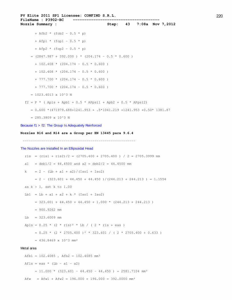
PV Elite 2011 SP1 Licensee: CONFIND S.R.L. FileName : P3902-BC -------------------------------------- Nozzle Summary : Step: 43 7:08a Nov 7,2012
220
+ Afb2 * (fob2 - 0.5 * p)
+ Afp1 * (fop1 - 0.5 * p)
+ Afp2 * (fop2 - 0.5 * p)
= (2867.987 + 392.000 ) * (204.174 - 0.5 * 0.600 )
+ 102.408 * (204.174 - 0.5 * 0.600 )
+ 102.408 * (204.174 - 0.5 * 0.600 )
+ 777.700 * (204.174 - 0.5 * 0.600 )
+ 777.700 * (204.174 - 0.5 * 0.600 )
= 1023.4013 x 10^3 N
f2 = P * ( Apls + Apb1 + 0.5 * APpsi1 + Apb2 + 0.5 * APpsi2)
= 0.600 *(471979.688+1241.953 + .5*1041.219 +1241.953 +0.50* 1381.87
= 285.3809 x 10^3 N
Because f1 > f2: The Group Is Adequately Reinforced
Nozzles R16 and R14 are a Group per EN 13445 para 9.6.4
-------------------------------------------------------
The Nozzles are Installed In an Ellipsoidal Head
ris = (ris1 + ris2)/2 = (2705.400 + 2705.400 ) / 2 = 2705.3999 mm
a1 = deb1/2 = 44.4500 and a2 = deb2/2 = 44.4500 mm
k = 2 - (Lb + a1 + a2)/(Iso1 + Iso2)
= 2 - (323.601 + 44.450 + 44.450 )/(244.213 + 244.213 ) = 1.1554
as k > 1, set k to 1.00
Lb1 = Lb + a1 + a2 + k * (Iso1 + Iso2)
= 323.601 + 44.450 + 44.450 + 1.000 * (244.213 + 244.213 )
= 900.9262 mm
Lb = 323.6009 mm
Apls = 0.25 * (2 * ris)² * Lb / ( 2 * ris + eas )
= 0.25 * (2 * 2705.400 )² * 323.601 / ( 2 * 2705.400 + 0.433 )
= 436.8469 x 10^3 mm²
Metal area
Afb1 = 102.4085 , Afb2 = 102.4085 mm²
Afls = eas * (Lb - a1 - a2)
= 11.000 * (323.601 - 44.450 - 44.450 ) = 2581.7104 mm²
Afw = Afw1 + Afw2 = 196.000 + 196.000 = 392.0000 mm²

PV Elite 2011 SP1 Licensee: CONFIND S.R.L. FileName : P3902-BC -------------------------------------- Nozzle Summary : Step: 43 7:08a Nov 7,2012
221
APsil = 1381.8744 and APpsi2 = 1360.8990 mm²
f1 = (Afls + Afw ) * (fs - 0.5 * p)
+ Afb1 * (fob1 - 0.5 * p)
+ Afb2 * (fob2 - 0.5 * p)
+ Afp1 * (fop1 - 0.5 * p)
+ Afp2 * (fop2 - 0.5 * p)
= (2581.710 + 392.000 ) * (204.174 - 0.5 * 0.600 )
+ 102.408 * (204.174 - 0.5 * 0.600 )
+ 102.408 * (204.174 - 0.5 * 0.600 )
+ 777.700 * (204.174 - 0.5 * 0.600 )
+ 777.700 * (204.174 - 0.5 * 0.600 )
= 965.0420 x 10^3 N
f2 = P * ( Apls + Apb1 + 0.5 * APpsi1 + Apb2 + 0.5 * APpsi2)
= 0.600 *(436846.844+1241.953 + .5*1381.874 +1241.953 +0.50* 1360.89
= 264.3988 x 10^3 N
Because f1 > f2: The Group Is Adequately Reinforced
No interference violations have been detected !
Please refer to the nozzles treated as isolated openings for more information
PV Elite is a trademark of Intergraph CADWorx & Analysis Solutions, Inc. 2011

PV Elite 2011 SP1 Licensee: CONFIND S.R.L. FileName : P3902-BC -------------------------------------- Vessel Design Summary : Step: 44 7:08a Nov 7,2012
222
Design Code: European Std: EN13445-3 2009(E) Issue 1 (2009-07)
Diameter Spec : 3000.000 mm ID
Vessel Design Length, Tangent to Tangent 10450.00 mm
Specified Datum Line Distance 0.00 mm
Shell Material Specification P355NH
Nozzle Material Specification P285QH
Nozzle Material Specification P355NH
Re-Pad Material Specification P355NH
Re-Pad Material Specification P235GH
Internal Design Temperature 60 C
Internal Design Pressure 0.600 MPa
External Design Temperature -20 C
External Design Pressure 2.180 MPa
Maximum Allowable Working Pressure 1.093 MPa
Hydrostatic Test Pressure 1.504 MPa
Wind Design Code ASCE-93
Earthquake Design Code UBC-97
Element Pressures and MAWP: MPa
Element Desc | Design Pres. | External | M.A.W.P | Corrosion
| + Stat. head | Pressure | | Allowance
---------------------------------------------------------------------
FUND ELIPSOIDAL 1 0.600 0.000 1.093 3.0000
VIROLA 0.600 0.000 1.489 3.0000
FUND ELIPSOIDAL 2 0.600 0.000 1.294 3.0000
Element "To" Elev Length Element Thk R e q d T h k Joint Eff
Type mm mm mm Int. Ext. Long Circ
-----------------------------------------------------------------------
Ellipse 50.0 50.0 14.0 9.5 No Calc 1.00 1.00
Cylinder 10400.0 10350.0 14.0 7.4 No Calc 1.00 1.00
Ellipse 10450.0 50.0 14.0 8.9 No Calc 1.00 1.00
Element thicknesses are shown as Nominal if specified, otherwise are Minimum

PV Elite 2011 SP1 Licensee: CONFIND S.R.L. FileName : P3902-BC -------------------------------------- Vessel Design Summary : Step: 44 7:08a Nov 7,2012
223
Saddle Parameters:
Saddle Width 400.000 mm
Saddle Bearing Angle 120.000 deg.
Centerline Dimension 2000.000 mm
Wear Pad Width 500.000 mm
Wear Pad Thickness 14.000 mm
Wear Pad Bearing Angle 127.000 deg.
Distance from Saddle to Tangent 685.000 mm
Baseplate Length 2400.000 mm
Baseplate Thickness 20.000 mm
Baseplate Width 400.000 mm
Number of Ribs (including outside ribs) 4
Rib Thickness 20.000 mm
Web Thickness 20.000 mm
Height of Center Web 448.000 mm
Summary of Maximum Saddle Loads, Operating Case :
Maximum Vertical Saddle Load 95112.34 N
Maximum Transverse Saddle Shear Load 14091.53 N
Maximum Longitudinal Saddle Shear Load 28183.05 N
Summary of Maximum Saddle Loads, Hydrotest Case :
Maximum Vertical Saddle Load 483099.19 N
Maximum Transverse Saddle Shear Load 2233.84 N
Maximum Longitudinal Saddle Shear Load 1371.65 N
Weights:
Fabricated - Bare W/O Removable Internals 15602.6 kg
Shop Test - Fabricated + Water ( Full ) 96503.0 kg
Shipping - Fab. + Rem. Intls.+ Shipping App. 15602.6 kg
Erected - Fab. + Rem. Intls.+ Insul. (etc) 15602.6 kg
Empty - Fab. + Intls. + Details + Wghts. 15602.6 kg
Operating - Empty + Operating Liquid (No CA) 15602.6 kg
Field Test - Empty Weight + Water (Full) 96503.0 kg
PV Elite is a trademark of Intergraph CADWorx & Analysis Solutions, Inc. 2011