Embed Size (px)
Citation preview

1
Bottoms Gallery (Pvt) Ltd.Ltd
Bulbul Tower, Dighir Chala, Chandana, Gazipur(23.994592, 90.382016)
11th May 2014

2
Punching shear in flat slabs requires immediate action

3
• Flat slabs were observed at all levels, some of which were subject to storage loads. • There were no shear links referred to in the drawings. • Detail Engineering Assessment required to determine capacity of slab with regard to punching shear.
Flat slab at Level 4
Stresses in flat slabs

4
Stress levels in columns
5
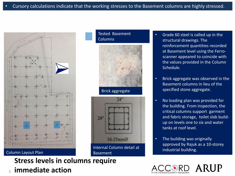
• Cursory calculations indicate that the working stresses to the Basement columns are highly stressed.
• Grade 60 steel is called up in the structural drawings. The reinforcement quantities recorded at Basement level using the Ferro-scanner appeared to coincide with the values provided in the Column Schedule.
• Brick aggregate was observed in the Basement columns in lieu of the specified stone aggregate.
• No loading plan was provided for the building. From inspection, the critical columns support garment and fabric storage, toilet slab build-up on levels one to six and water tanks at roof level.
• The building was originally approved by Rajuk as a 10-storey industrial building.
Stress levels in columns require immediate action
Tested Basement Columns
Internal Column detail at BasementColumn Layout Plan
Brick aggregate

6
Design drawings indicate stone aggregate concrete was to be used. Basement columns opened up clearly show concrete contains brick aggregate
Column aggregate type

7
Critical Internal Column at Level 5 Water tanks on Level 7 (current roof)
Storage of fabric rolls on Level 1 Garment storage at Level 4
Stress levels in columns require immediate action

8
Heavy Loading (A) - Storage

9
The floor load management system was incomplete as no loading plans were observed for any of the levels. Garment storage was present on 2nd to 6th floors, and fabric storage was present on 1st floor.
Heavy Loading (A) - Storage
Finished garment storage on 6th floorsLocation of garment storage on 2nd to 6th floors
Location of observed heavy loading imposed by garment storage

10
Storage for rolls of fabric was present on 1st floor.
Heavy Loading (A) - Storage
Rolls of fabric stored on 1st floorLocation of fabric storage on 1st floor
Location of observed heavy loading imposed by rolls of fabric
11
Heavy Loading (B) – Water Storage Tanks
12
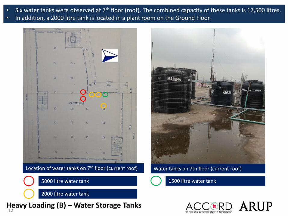
• Six water tanks were observed at 7th floor (roof). The combined capacity of these tanks is 17,500 litres.• In addition, a 2000 litre tank is located in a plant room on the Ground Floor.
Heavy Loading (B) – Water Storage Tanks
Water tanks on 7th floor (current roof)Location of water tanks on 7th floor (current roof)
5000 litre water tank
2000 litre water tank
1500 litre water tank
13
Heavy Loading (C) – Floor build-up in toilet areas

14
• Slab build up was present in the toilet areas. • The average build-up depth observed was 308mm.
Heavy Loading (C) - Floor build-up in toilet reas
Toilet block on 6th floorLocation of toilets on 1st to 6th floors
Location of toilets
15
Heavy Loading (D) – Ground Floor Brick Walls
16
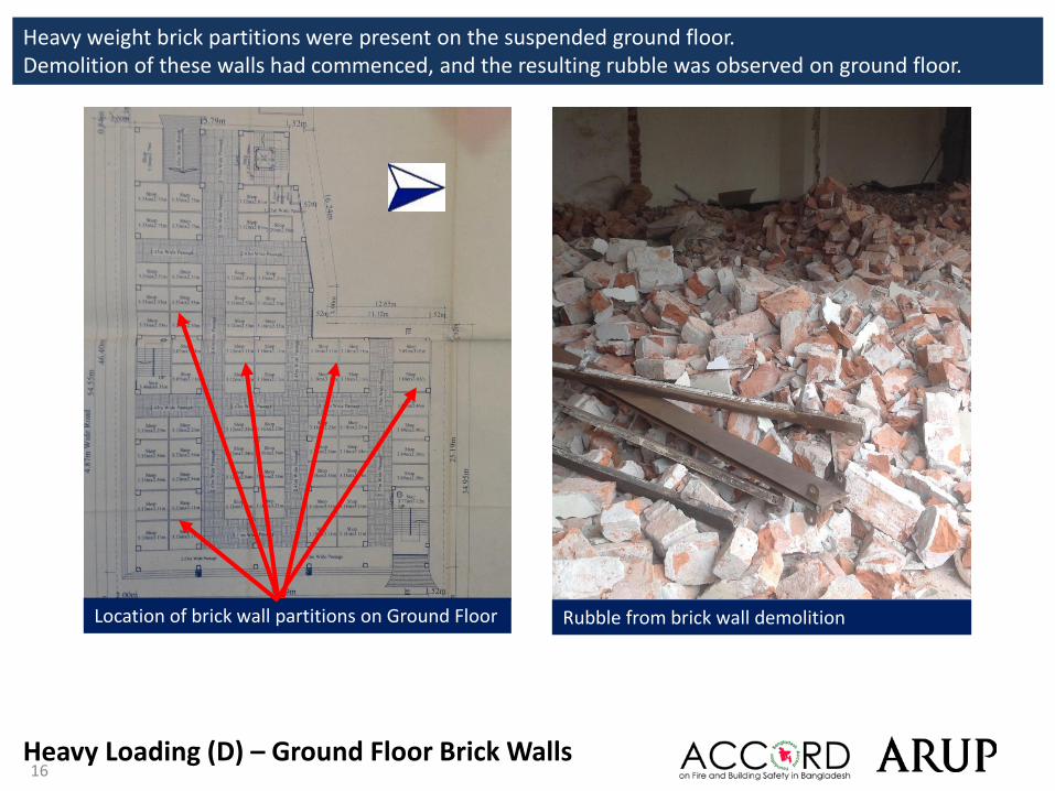
Heavy weight brick partitions were present on the suspended ground floor. Demolition of these walls had commenced, and the resulting rubble was observed on ground floor.
Heavy Loading (D) – Ground Floor Brick Walls
Rubble from brick wall demolitionLocation of brick wall partitions on Ground Floor

17
Lateral stability system unclear
18
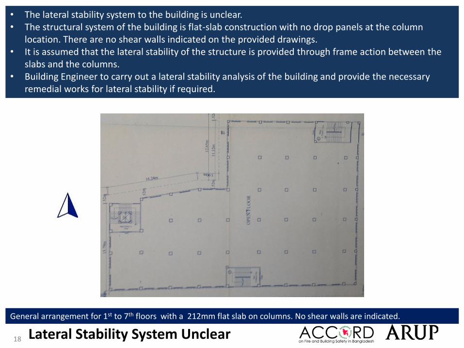
• The lateral stability system to the building is unclear. • The structural system of the building is flat-slab construction with no drop panels at the column
location. There are no shear walls indicated on the provided drawings. • It is assumed that the lateral stability of the structure is provided through frame action between the
slabs and the columns. • Building Engineer to carry out a lateral stability analysis of the building and provide the necessary
remedial works for lateral stability if required.
Lateral Stability System Unclear
General arrangement for 1st to 7th floors with a 212mm flat slab on columns. No shear walls are indicated.

19
Floor cantilevers

20
Cantilever slabs were observed on the East and South elevations of the building. Building Engineer to check structural adequacy of the cantilever, and propose and implement any strengthening works if required.
Cantilever on East elevation. Cantilever on South elevation.
Floor cantilevers

21
Inconsistencies in documents provided
22
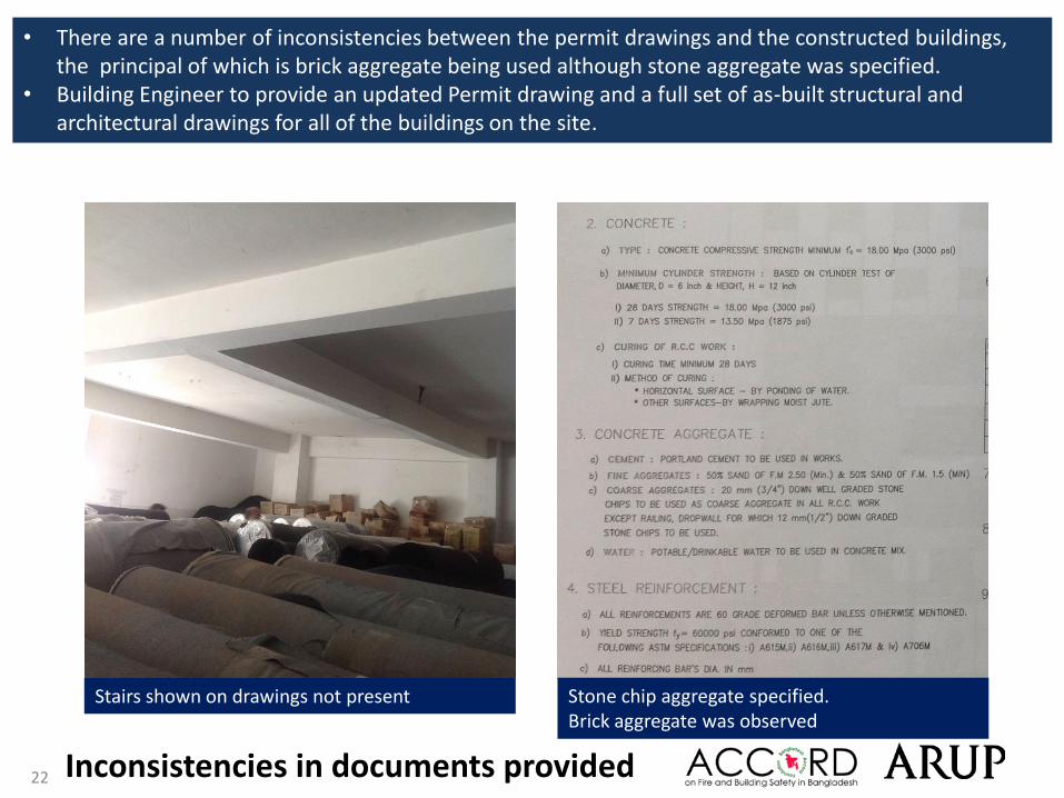
• There are a number of inconsistencies between the permit drawings and the constructed buildings, the principal of which is brick aggregate being used although stone aggregate was specified.
• Building Engineer to provide an updated Permit drawing and a full set of as-built structural and architectural drawings for all of the buildings on the site.
Stairs shown on drawings not present Stone chip aggregate specified. Brick aggregate was observed
Inconsistencies in documents provided

23
Lightweight roof structures
24
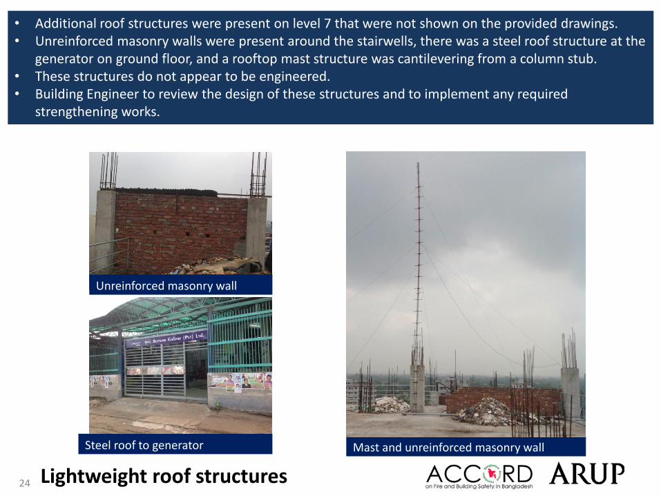
• Additional roof structures were present on level 7 that were not shown on the provided drawings. • Unreinforced masonry walls were present around the stairwells, there was a steel roof structure at the
generator on ground floor, and a rooftop mast structure was cantilevering from a column stub. • These structures do not appear to be engineered. • Building Engineer to review the design of these structures and to implement any required
strengthening works.
Lightweight roof structures
Mast and unreinforced masonry wallSteel roof to generator
Unreinforced masonry wall

25
Priority Actions

26
Problems Observed1. Heavy imposed loading (4 issues):
A. StorageB. Water storage tanksC. Floor build-up in toilet areasD. Ground Floor brick walls
2. Stress levels in columns
3. Lateral stability system unclear
4. Floor cantilevers
5. Missing documentation and Inconsistencies in documents provided
6. Lightweight roof structures
27
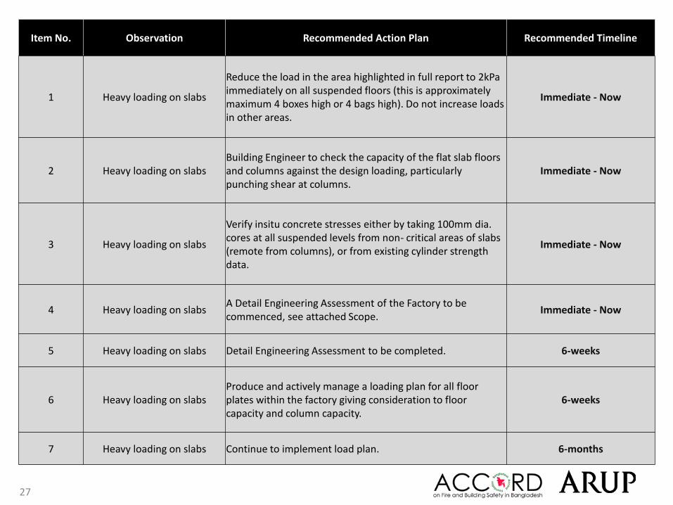
Item No. Observation Recommended Action Plan Recommended Timeline
1 Heavy loading on slabs
Reduce the load in the area highlighted in full report to 2kPa immediately on all suspended floors (this is approximately maximum 4 boxes high or 4 bags high). Do not increase loads in other areas.
Immediate - Now
2 Heavy loading on slabsBuilding Engineer to check the capacity of the flat slab floors and columns against the design loading, particularly punching shear at columns.
Immediate - Now
3 Heavy loading on slabs
Verify insitu concrete stresses either by taking 100mm dia. cores at all suspended levels from non- critical areas of slabs (remote from columns), or from existing cylinder strength data.
Immediate - Now
4 Heavy loading on slabsA Detail Engineering Assessment of the Factory to be commenced, see attached Scope.
Immediate - Now
5 Heavy loading on slabs Detail Engineering Assessment to be completed. 6-weeks
6 Heavy loading on slabsProduce and actively manage a loading plan for all floor plates within the factory giving consideration to floor capacity and column capacity.
6-weeks
7 Heavy loading on slabs Continue to implement load plan. 6-months

28
This Schedule develops a minimum level of information, Analysis and testing expected as part of a Detail Engineering Assessment.The Building(s) have been visually assessed and it is deemed necessary that a detailed engineering assessment be carried out by a competent Engineering Team employed by the factory Owner. This Request should be read in conjunction with the BUET developed Tripartite Guideline document for Assessment of Structural Integrity of Existing RMG Factory Buildings in Bangladesh (Tripartite Document), the latest version of this document should be referenced. T his document also gives guidance on required competency of Engineering Team.
We expect that the following will be carried out:1. Development of Full Engineering As-Built Drawings showing Structure, loading, elements, dimensions , levels, foundations and framing on Plan,
Section and Elevational drawings .2. The Engineering team are to carry out supporting calculations with a model based design check to assess the safety and serviceability of the building
against loading as set out in BNBC-2006, Lower rate provisions can be applied in accordance with the Tripartite Guidelines following international engineering practice, justification for these lower rate provisions must be made.
3. A geotechnical Report describing ground conditions and commenting on foundation systems used/proposed.4. A report on Engineering tests carried out to justify material strengths and reinforcement content in all key elements studied.5. Detailed load plans shall be prepared for each level showing current and potential future loading with all key equipment items shown with associated
loads.6. The Engineering team will prepare an assessment report that covers the following:
• As-Built drawings including• Plans at each level calling up and dimensioning all structural components • Cross sectional drawings showing structural beams, slabs, floor to floor heights, roof build-ups and Basic design information of the
structure• Highlight any variation between As-built compared to the designed structure• Results of testing for strength and materials• Results of geotechnical assessment and testing/investigation• Details of loading, inputs and results of computer modelling• Commentary on adequacy/inadequacy of elements of the structure• Schedule of any required retrofitting required for safety or performance of Structure
Any proposals for Retrofitting to follow guidance developed in the Tripartite Document
Detail Engineering Assessment

29
Item No. Observation Recommended Action Plan Recommended Timeline
8Stress levels in basement
columns
As part of Detail Engineering Assessment (see Item 1), Building Engineer to review design, loads and column stresses in basement columns.
Immediate - Now
9Stress levels in basement
columns
Verify insitu concrete stresses either by 100mm diameter cores from, or existing cylinder strength data from min. 4 basement columns. Reinforcement quantities also to be confirmed.
Immediate - Now
10Stress levels in basement
columnsInput data from column design review into Loading Plan (see Item 1).
6-weeks
11Stress levels in basement
columnsContinue to implement load plan. 6-months
12Lateral stability system
unclear
As part of Detail Engineering Assessment (see Item 1), Building Engineer to carry out a stability analysis of the full 7 storey building.
6-weeks
13Lateral stability system
unclearPropose additional stability works if necessary. 6-weeks
14Lateral stability system
unclearImplement remedial action if required. 6-months

30
Item No. Observation Recommended Action Plan Recommended Timeline
15 Floor CantileversAs part of Detail Engineering Assessment (see Item 1), Building Engineer to assess the cantilever slab design for the floor and façade loads applied.
6-weeks
16 Floor Cantilevers Carry out any remedial or strengthening works as required. 6-months
17Inconsistencies in documents
providedBuilding Engineer to update the structural and architectural drawings to reflect the as-built layouts.
6-months
18 Lightweight roof structuresLightweight structures to be checked to ensure adequacy for code vertical and wind loads by the Building Engineer.
6-months
19 Lightweight roof structures Undertake strengthening if required. 6-months
20 Lightweight roof structuresBuilding Engineer to produce appropriate documentation and as-built drawings.
6-months