Embed Size (px)
Citation preview

BOOMERANG TORUS
Aerobatic Sport Jet for 20 to 34 lbs (P80 to P160) thrust turbines.
Specifications:Span... 83" (2209mm.) Span with Wingtip Tanks 90" (2286mm.)Length...87" (2108mm.)Weight 29 Lbs.(13.15 Kilo)Radio Required 6 to 11 channels.Servos.. 9 to 11, from 5 to 12 kilo torque.
Safety PrecautionsThe Torus turbine model is designed for experienced modellers. This model is not recommended for begin-ners to R/C flying and should not be attempted by those with insufficient building and flying experience. This manual is for guidance only. If you are unsure of any model building techniques, seek help from an experi-
enced model builder or contact Boomerang RC Jets, LLC. for assistance. Jet models are dangerous if construction is carelessly or incorrectly carried out. As the building assembly of this kit is out of our control after point of sale, no liability is accepted by Boomerang RC Jets, LLC. for any accident or loss, however caused. Purchase of this kit implies acceptance of these conditions by the purchaser. To decline these
terms, return the unused kit to your supplier for full refund.
Boomerang RC Jets, LLC. Website:www.Boomerang-RC-Jets.com

NOTES ON HORN POSITIONSMount the horns so the clevis holes are 1/4" (6mm) behind the hinge line for the ailerons to give differential and on the hinge line for rudders and elevators.But on the FLAP horns, move the horn bolt rearwards about 1"(25mm.) from hinge line and re-drill the hole for the clevis back so that the hole in the plastic flag is a full 3/4" back behind the hinge line. This will allow the flap to drop almost to 90 degrees full deflection. Insert all hinges and check range of
movement, then apply thin CA glue.
As With all ARF Kits, it is essential to make a thorough check of all glue joints and add epoxy or CA glue if required.
2
Be sure to apply thin C.A. glue to both sides of each hinge. Then pin each hinge from below using cocktail sticks, fore and aft of the hinge line. Do not pierce the top surface.
10Cocktail stick pin
Cocktail stick pin
Pushrods
4mm
8
8
8
16
8
4
4
8
8
84 x 100mm
58mm
100mm
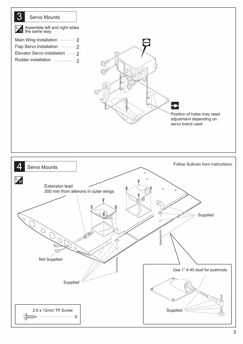
Follow Sullivan horn instructions.
2.6 x 12mm TP Screw8
Use 1” 4-40 stud for pushrods
Supplied
Supplied
Supplied
Not Supplied

2.5mm Hex Wrench
84 x 10mm Bolt
4 x 10mm Bolt
4 x 10mm Bolt
Tip Tank Installation
Regular wing tips.
44 x 10mm Bolt
6mm 4
4
4
Fix the alloy rods in the wing with the bolts supplied.Use glossy plastic packing tape or similar over the wing to ensure release, then use 5 minute epoxy glue in the wing tips. Line up and press the tip home while the glue sets. Then slack off the bolts and release the tip with the tabs in place.

3 x16mm TP Screw
3 x16mm TP ScrewNot Supplied
Not Supplied
8
Not Supplied
Up to 2.75 inches
Not Supplied

9
Be sure to glue the rudder hinges securely. This is Vital for safe flying!
1 metre extension
1.25 metre extension
2.6 x 12mm TP Screw
82.6 x 12mm TP Screw
Cut away covering film
Cut away covering film

Supplied.
Supplied.
Use short lengths of 4-40 stud and Sullivan Clevises and horns supplied.
2.6 x 12mm TP Screw
2.6 x 12mm TP Screw 8

13Assemble left and right sides the same way.
Assemble left and right sides the same way.
Supplied
Supplied
4-40 stud pushrod
Rudders

2
44 x 10mm Bolt
2
2
Assemble left and right sides the same way
.
14
8mm Alloy Rods
6mm Alloy Rods
Carbon fibre spars
6mm Alloy Rods8mm Alloy Rods
Carbon fibre spars
4 x 10mm Bolt

15
16
2
2
2
4 x 16mm Screw
4mm Lock Nut
4mm Washer
Additional safety fitting to stabilisor
With tailplane (Stab.) firmly screwed down, pass a 3.6mm drill through the holes in the fins and drill a hole through the metal tongue projecting down from the Stab. Remove the Stab and tap the new hole in the tongue out to 4mm thread. Repeat the process through the other fin. During assembly apply the 4mm X16mm bolt through the fins and the tongues and lock in place with the 4mm nylock nuts and washers supplied. If a 4mm tap is not available drill the hole in the tongue out to 4mm and assemble the same way.
4 x 20mm Bolt
4 x 20mm Bolt
4 x 20mm Bolt4

17
18
Not Supplied
Not Supplied
2 x 8mm TP Screw
2 x 8mm TP Screw8
Not Supplied
Not Supplied
Not Supplied
Not Supplied
55mm

19
20
Turbine installation
Remove the cross braces which are marked "cut" by cutting at the dotted lines. Do the same with the cross braces marked "cut" in the hatch. You may prefer to fix the turbine with the 4mm bolts and spike nuts supplied or use self tapping screws if preferred
Air bottle installation
4
4
Cut off at the dotted line
Cut off at the dotted line
4 x 15mm Bolt
4mm Mount Nut
4mm Mount Nut
4 x 15mm Bolt
Not Supplied

21
22
Battery and RX
Fuel and Ancillaries Tray
2.6 x 12mm TP Screw
2.6 x 12mm TP Screw4
2.6 x 12mm TP Screw
2.6 x 12mm TP Screw4

23
24
25
It is essential to use Velcro double sided Straps or large tie wraps through the vertical parts of the formers to fix the fuel tank.
2.6 x 12mm TP Screw10
4mm Blind Nut
4mm Washer
4 x 15mm Bolt
1
1
1
4mm Blind Nut
4 x 15mm Bolt4mm Washer

25mm
0mm
25mm
40mm
0mm
40mm
25mm
0mm
20mm
26
The flap should drop as near to 90 degrees as possible
For your first flights, take the CG with the model “dry” all assembled with the retracts down and the hatch removed. If you are using lightweight batteries you will need to add up to 16 ounces of weight in the nose.The CG should be at the centre of the front carbon fibre wing spar.
ELEVATOR
RUDDER
AILERON
FLAP

Supplementary instruction for Torus Wing Bag
Due to a late design change in the wing tip tanks assembly which permanently fixes the alloy rods in place, it is necessary to cut a slit in their protective bags to
allow the tanks to be put in.
Make a straight cut, starting from the open end for approximately 18" along the bottom of the bag. Insert the tiptank, pointed end first. Once the tank is in the bag,
the opening can be held together using elastic bands or Velcro or similar fixing method.

IMPORTANT WARNING.
READ THROUGH BEFORE ASSEMBLING OR FLYING YOUR KIT.
Just as in any full size aircraft, any RIC model aircraft can be made to fail, be it a wing folding or a fuselage breaking under too high a load. Model RIC aircraft have a maximum safe G limit. Because you are not in the plane it is difficult to judge the G during flight, and it is very easy to exceed the limits of the aircraft. This is particularly important if you install a turbine larger or more powerful than the power band specified for that particular kit. This negates any airframe warranty straight away.
All our designs are thoroughly test flown before the kit is released for sale. Turbine powered RIC model aircraft are not manufactured to withstand unlimited G forces. When flying your Boomerang Jet, be aware of the high loads which can be in excess of the airframes capability to handle. Respect the airframe as you would when flying a full size aircraft. Fit a turbine only up to the specified power.
Understand that if you perfonn a snap roll, wall, blender, knife edge loop or any similar manoeuvre, or pull hard on the elevator, particularly at high speed, you can over stress the airframe by up to15 G or more. At 15 G, the 27 lbs (12.2 Kilo) model effectively weighs over400 lbs (184 kilo), and though it may be for only a few seconds, the strain on the airframe is huge. Your model may survive those hard manoeuvres a few times, but eventually the cumulative damage will tell and airframe break up can occur.
It is common practice for any manufacturer not to replace an airframe which breaks in the air or upon landing. Manufacturers may replace airframes when they have noticed many incidences of the same failure and it is detennined that there was a design fault or repeated manufacturing error. If you break an airframe, and you are the only one to do so, then it is highly unlikely to be the fault of the manufacturer. Fly safely, and avoid full throttle operation other than at low airspeeds.
RIC model jets are not toys! If misused, they can cause serious bodily hann and property damage. Fly only in open areas, and AMA (Academy of Model Aeronautics) or BMFA (British Model Flying Association) or your country's approved flying sites. Follow all manufacturer instructions included with your plane, radio, servo's, batteries and engine. Each kit is guaranteed to be free from defects in both material and workmanship at the date of purchase. Warranty does not cover any component assembled by the customer. All parts of high stress must be inspected and reinforced if necessary by a competent builder.
Some parts should be examined, and if necessary, glued again. High stress areas such as firewalls, motor mounts, wing mounts, landing gear mounts, etc., are areas of high concern. Seek help if necessary.
In no case shall Boomerang RC Jets, LLC. warranty cover any product which is not manufactured by Boomerang RC Jets, LLC. The liability to the manufacturer cannot exceed the original cost of the purchased item.
Further, Boomerang RC Jets, LLC. reserves the right to change or modify this warranty without notice. In that Boomerang RC Jets, LLC. has no control over the assembly or materials used by the builder of the model during final assembly, no liability shall be assumed nor accepted for any damage resulting from the use of the final user-assembled product. By using the user assembled product, the user accepts all resulting liability. The kits manufacturers have provided you with a top quality, thoroughly tested kit and instructions, but ultimately the quality and flying ability of your finished model depends on how you build it. Therefore, we cannot in any way guarantee the performance of your completed model, and no representations are expressed or implied as to the performance or safety of your completed model. It is the use�s responsibility to inspect each component for airworthiness.