Embed Size (px)
Citation preview

Book E:Enhanced PowerPC Architecture
Version 1.0
May 7, 2002

Third Edition (Dec 2001)
The following paragraph does not apply to the United Kingdom or any country where such provisions are inconsistentwith local law: INTERNATIONAL BUSINESS MACHINES CORPORATION PROVIDES THIS DOCUMENT “AS IS”WITHOUT WARRANTY OF ANY KIND, EITHER EXPRESSED OR IMPLIED, INCLUDING, BUT NOT LIMITED TO,THE IMPLIED WARRANTIES OF MERCHANTABILITY AND FITNESS FOR A PARTICULAR PURPOSE. Somestates do not allow disclaimer of express or implied warranties in certain transactions; therefore, this statement maynot apply to you. IBM does not warrant that the use of the information herein shall be free from third party intellectualproperty claims.
IBM does not warrant that the contents of this document will meet your requirements or that the document is error-free.Changes are periodically made to the information herein; these changes will be incorporated in new editions of thedocument. IBM may make improvements and or changes in the product(s) and/or program(s) described in thisdocument at any time. This document does not imply a commitment by IBM to supply or make generally available theproduct(s) described herein.
No part of this document may be reproduced or distributed in any form or by any means, or stored in a data base orretrieval system, without the written permission of IBM.
Address comments about this document to:
IBM CorporationDepartment B5H / Building 6673039 Cornwallis Road P.O. Box 12195Research Triangle Park, NC 27709
Portions of the information in this document may have been published previously in the following related documents:The PowerPC Architecture: A Specification for a New Family of RISC Processors, Second Edition (1994)The IBM PowerPC Embedded Environment: Architectural Specifications for IBM PowerPC Embedded Controllers,Second Edition (1998)
IBM may have patents or pending patent applications covering the subject matter in this document. The furnishing ofthis document does not give you any license to these patents. You can send license inquiries, in writing, to the IBMDirector of Licensing, North Castle Drive, Armonk, NY 10504, United States of America.
Copyright International Business Machines Corporation 1993, 2000. All rights reserved.
Printed in the United States of America.
The following terms are trademarks of IBM Corporation:
IBM PowerPC
Other terms which are trademarks are the property of their respective owners.
ii Book E: Enhanced PowerPC Architecture Version 1.0 07 May 02

Preface
This release represents the initial release of the Book E architecture specification.
Many thanks to those in Motorola and IBM who have reviewed this document andcontributed so much to cleaning up after my carelessness.
The Editor
07 May 02 Preface iii

iv Book E: Enhanced PowerPC Architecture Version 1.0 07 May 02

Table of Contents
Chapter 1. Introduction . . . . . . . . . . . . . . . . . . . . . . . . . . . . . . . . . . . . . . . . . . . . . . . . . . . . . . . 11.1 Overview . . . . . . . . . . . . . . . . . . . . . . . . . . . . . . . . . . . . . . . . . . . . . . . . . . . . . 11.2 Compatibility with the PowerPC Architecture . . . . . . . . . . . . . . . . . . . . . . . . . . 11.3 32-bit Book E Implementations . . . . . . . . . . . . . . . . . . . . . . . . . . . . . . . . . . . . 11.4 Instruction Mnemonics and Operands . . . . . . . . . . . . . . . . . . . . . . . . . . . . . . . 21.5 Document Conventions . . . . . . . . . . . . . . . . . . . . . . . . . . . . . . . . . . . . . . . . . . 21.5.1 Notes . . . . . . . . . . . . . . . . . . . . . . . . . . . . . . . . . . . . . . . . . . . . . . . . . . . . . 21.5.2 Notation. . . . . . . . . . . . . . . . . . . . . . . . . . . . . . . . . . . . . . . . . . . . . . . . . . . 31.5.3 Definitions . . . . . . . . . . . . . . . . . . . . . . . . . . . . . . . . . . . . . . . . . . . . . . . . . 41.5.4 Reserved Fields . . . . . . . . . . . . . . . . . . . . . . . . . . . . . . . . . . . . . . . . . . . . . 81.5.5 Preserved Fields. . . . . . . . . . . . . . . . . . . . . . . . . . . . . . . . . . . . . . . . . . . . . 91.5.6 Allocated Fields . . . . . . . . . . . . . . . . . . . . . . . . . . . . . . . . . . . . . . . . . . . . . 91.5.7 Description of Instruction Operation . . . . . . . . . . . . . . . . . . . . . . . . . . . . 101.6 Book E Overview . . . . . . . . . . . . . . . . . . . . . . . . . . . . . . . . . . . . . . . . . . . . . . 131.7 Instruction Formats. . . . . . . . . . . . . . . . . . . . . . . . . . . . . . . . . . . . . . . . . . . . 181.7.1 Instruction Fields. . . . . . . . . . . . . . . . . . . . . . . . . . . . . . . . . . . . . . . . . . . 221.8 Classes of Instructions . . . . . . . . . . . . . . . . . . . . . . . . . . . . . . . . . . . . . . . . . 251.8.1 Defined Instruction Class. . . . . . . . . . . . . . . . . . . . . . . . . . . . . . . . . . . . . 251.8.2 Allocated Instruction Class . . . . . . . . . . . . . . . . . . . . . . . . . . . . . . . . . . . 261.8.3 Preserved Instruction Class . . . . . . . . . . . . . . . . . . . . . . . . . . . . . . . . . . . 271.8.4 Reserved Instruction Class. . . . . . . . . . . . . . . . . . . . . . . . . . . . . . . . . . . . 271.9 Forms of Defined Instructions . . . . . . . . . . . . . . . . . . . . . . . . . . . . . . . . . . . . 281.9.1 Preferred Instruction Forms . . . . . . . . . . . . . . . . . . . . . . . . . . . . . . . . . . . 281.9.2 Invalid Instruction Forms. . . . . . . . . . . . . . . . . . . . . . . . . . . . . . . . . . . . . 281.10 Optionality . . . . . . . . . . . . . . . . . . . . . . . . . . . . . . . . . . . . . . . . . . . . . . . . . . 291.11 Storage Addressing . . . . . . . . . . . . . . . . . . . . . . . . . . . . . . . . . . . . . . . . . . . . 291.11.1 Storage Operands . . . . . . . . . . . . . . . . . . . . . . . . . . . . . . . . . . . . . . . . . . 301.11.2 Effective Address Calculation . . . . . . . . . . . . . . . . . . . . . . . . . . . . . . . . . . 311.11.2.1 Data Storage Addressing Modes . . . . . . . . . . . . . . . . . . . . . . . . . . . . . 311.11.2.2 Instruction Storage Addressing Modes . . . . . . . . . . . . . . . . . . . . . . . . 321.11.3 Byte Ordering . . . . . . . . . . . . . . . . . . . . . . . . . . . . . . . . . . . . . . . . . . . . . 331.11.3.1 Structure Mapping Examples . . . . . . . . . . . . . . . . . . . . . . . . . . . . . . . 331.11.3.2 Instructions Byte Ordering . . . . . . . . . . . . . . . . . . . . . . . . . . . . . . . . . 351.11.3.3 Data Byte Ordering . . . . . . . . . . . . . . . . . . . . . . . . . . . . . . . . . . . . . . 351.11.3.4 Integer Load and Store Byte-Reverse Instructions. . . . . . . . . . . . . . . . 361.11.3.5 Origin of Endian. . . . . . . . . . . . . . . . . . . . . . . . . . . . . . . . . . . . . . . . . 371.12 Synchronization . . . . . . . . . . . . . . . . . . . . . . . . . . . . . . . . . . . . . . . . . . . . . . 381.12.1 Context Synchronization . . . . . . . . . . . . . . . . . . . . . . . . . . . . . . . . . . . . . 381.12.2 Execution Synchronization . . . . . . . . . . . . . . . . . . . . . . . . . . . . . . . . . . . 38
Chapter 2. Processor Control . . . . . . . . . . . . . . . . . . . . . . . . . . . . . . . . . . . . . . . . . . . . . . . . . 392.1 Processor Control Registers . . . . . . . . . . . . . . . . . . . . . . . . . . . . . . . . . . . . . . 392.1.1 Machine State Register . . . . . . . . . . . . . . . . . . . . . . . . . . . . . . . . . . . . . . 392.1.2 Processor Identification Register. . . . . . . . . . . . . . . . . . . . . . . . . . . . . . . . 412.1.3 Processor Version Register . . . . . . . . . . . . . . . . . . . . . . . . . . . . . . . . . . . . 412.1.4 Software-Use Special Purpose Registers . . . . . . . . . . . . . . . . . . . . . . . . . . 422.1.5 Device Control Registers . . . . . . . . . . . . . . . . . . . . . . . . . . . . . . . . . . . . . 422.2 Processor Control Instructions. . . . . . . . . . . . . . . . . . . . . . . . . . . . . . . . . . . . 432.2.1 System Linkage Instructions . . . . . . . . . . . . . . . . . . . . . . . . . . . . . . . . . . 43
07 May 02 Table of Contents v

2.2.2 Processor Control Register Manipulation Instructions . . . . . . . . . . . . . . . 432.2.3 Instruction Synchronization Instruction. . . . . . . . . . . . . . . . . . . . . . . . . . 432.2.4 Auxiliary Processing Query Instruction . . . . . . . . . . . . . . . . . . . . . . . . . . 44
Chapter 3. Branch and Condition Register Operations . . . . . . . . . . . . . . . . . . . . . . . . 453.1 Branch Operations Overview . . . . . . . . . . . . . . . . . . . . . . . . . . . . . . . . . . . . . 453.2 Registers for Branch Operations . . . . . . . . . . . . . . . . . . . . . . . . . . . . . . . . . . 453.2.1 Condition Register . . . . . . . . . . . . . . . . . . . . . . . . . . . . . . . . . . . . . . . . . . 453.2.1.1 Condition Register setting for integer instructions . . . . . . . . . . . . . . . 463.2.1.2 Condition Register setting for store conditional instructions . . . . . . . . 473.2.1.3 Condition Register setting for floating-point instructions . . . . . . . . . . 473.2.1.4 Condition Register setting for compare instructions . . . . . . . . . . . . . . 473.2.2 Link Register . . . . . . . . . . . . . . . . . . . . . . . . . . . . . . . . . . . . . . . . . . . . . . 483.2.3 Count Register . . . . . . . . . . . . . . . . . . . . . . . . . . . . . . . . . . . . . . . . . . . . . 483.3 Branch Instructions . . . . . . . . . . . . . . . . . . . . . . . . . . . . . . . . . . . . . . . . . . . 493.4 Condition Register Instructions . . . . . . . . . . . . . . . . . . . . . . . . . . . . . . . . . . . 52
Chapter 4. Integer Operations . . . . . . . . . . . . . . . . . . . . . . . . . . . . . . . . . . . . . . . . . . . . . . . . 534.1 Integer Operations Overview . . . . . . . . . . . . . . . . . . . . . . . . . . . . . . . . . . . . . 534.2 Registers for Integer Operations. . . . . . . . . . . . . . . . . . . . . . . . . . . . . . . . . . . 534.2.1 General Purpose Registers . . . . . . . . . . . . . . . . . . . . . . . . . . . . . . . . . . . . 534.2.2 Integer Exception Register . . . . . . . . . . . . . . . . . . . . . . . . . . . . . . . . . . . . 534.3 Integer Instructions . . . . . . . . . . . . . . . . . . . . . . . . . . . . . . . . . . . . . . . . . . . . 554.3.1 Integer Load Instructions . . . . . . . . . . . . . . . . . . . . . . . . . . . . . . . . . . . . . 554.3.2 Integer Store Instructions . . . . . . . . . . . . . . . . . . . . . . . . . . . . . . . . . . . . 574.3.3 Integer Arithmetic Instructions . . . . . . . . . . . . . . . . . . . . . . . . . . . . . . . . 594.3.4 Integer Logical Instructions . . . . . . . . . . . . . . . . . . . . . . . . . . . . . . . . . . . 614.3.5 Integer Compare Instructions. . . . . . . . . . . . . . . . . . . . . . . . . . . . . . . . . . 624.3.6 Integer Trap Instructions . . . . . . . . . . . . . . . . . . . . . . . . . . . . . . . . . . . . . 624.3.7 Integer Rotate and Shift Instructions . . . . . . . . . . . . . . . . . . . . . . . . . . . . 634.3.8 Integer Exception Register Instructions . . . . . . . . . . . . . . . . . . . . . . . . . . 65
Chapter 5. Floating-Point Operations . . . . . . . . . . . . . . . . . . . . . . . . . . . . . . . . . . . . . . . . . 675.1 Overview . . . . . . . . . . . . . . . . . . . . . . . . . . . . . . . . . . . . . . . . . . . . . . . . . . . . 675.2 Registers for Floating-Point Operations . . . . . . . . . . . . . . . . . . . . . . . . . . . . . 695.2.1 Floating-Point Registers . . . . . . . . . . . . . . . . . . . . . . . . . . . . . . . . . . . . . . 695.2.2 Floating-Point Status and Control Register. . . . . . . . . . . . . . . . . . . . . . . . 695.3 Floating-Point Data . . . . . . . . . . . . . . . . . . . . . . . . . . . . . . . . . . . . . . . . . . . . 735.3.1 Data Format . . . . . . . . . . . . . . . . . . . . . . . . . . . . . . . . . . . . . . . . . . . . . . 735.3.2 Value Representation . . . . . . . . . . . . . . . . . . . . . . . . . . . . . . . . . . . . . . . . 745.3.3 Sign of Result . . . . . . . . . . . . . . . . . . . . . . . . . . . . . . . . . . . . . . . . . . . . . 765.3.4 Normalization and Denormalization . . . . . . . . . . . . . . . . . . . . . . . . . . . . . 775.3.5 Data Handling and Precision . . . . . . . . . . . . . . . . . . . . . . . . . . . . . . . . . . 785.3.6 Rounding. . . . . . . . . . . . . . . . . . . . . . . . . . . . . . . . . . . . . . . . . . . . . . . . . 795.4 Floating-Point Exceptions . . . . . . . . . . . . . . . . . . . . . . . . . . . . . . . . . . . . . . . 815.4.1 Invalid Operation Exception . . . . . . . . . . . . . . . . . . . . . . . . . . . . . . . . . . . 855.4.2 Zero Divide Exception . . . . . . . . . . . . . . . . . . . . . . . . . . . . . . . . . . . . . . . 885.4.3 Overflow Exception . . . . . . . . . . . . . . . . . . . . . . . . . . . . . . . . . . . . . . . . . 895.4.4 Underflow Exception . . . . . . . . . . . . . . . . . . . . . . . . . . . . . . . . . . . . . . . . 915.4.5 Inexact Exception . . . . . . . . . . . . . . . . . . . . . . . . . . . . . . . . . . . . . . . . . . 935.5 Floating-Point Execution Models . . . . . . . . . . . . . . . . . . . . . . . . . . . . . . . . . . 945.5.1 Execution Model for IEEE Operations . . . . . . . . . . . . . . . . . . . . . . . . . . . 945.5.2 Execution Model for Multiply-Add Type Instructions . . . . . . . . . . . . . . . . 965.6 Floating-Point Instructions . . . . . . . . . . . . . . . . . . . . . . . . . . . . . . . . . . . . . . 985.6.1 Floating-Point Load Instructions . . . . . . . . . . . . . . . . . . . . . . . . . . . . . . . 985.6.2 Floating-Point Store Instructions . . . . . . . . . . . . . . . . . . . . . . . . . . . . . . 1005.6.3 Floating-Point Move Instructions . . . . . . . . . . . . . . . . . . . . . . . . . . . . . . 1025.6.4 Floating-Point Arithmetic Instructions . . . . . . . . . . . . . . . . . . . . . . . . . . 1025.6.4.1 Floating-Point Elementary Arithmetic Instructions . . . . . . . . . . . . . . 1025.6.4.2 Floating-Point Multiply-Add Instructions . . . . . . . . . . . . . . . . . . . . . 1025.6.5 Floating-Point Rounding and Conversion Instructions . . . . . . . . . . . . . . 1035.6.6 Floating-Point Compare Instructions . . . . . . . . . . . . . . . . . . . . . . . . . . . 1045.6.7 Floating-Point Status and Control Register Instructions . . . . . . . . . . . . . 104
Chapter 6. Storage. . . . . . . . . . . . . . . . . . . . . . . . . . . . . . . . . . . . . . . . . . . . . . . . . . . . . . . . . . . 1076.1 Storage Model . . . . . . . . . . . . . . . . . . . . . . . . . . . . . . . . . . . . . . . . . . . . . . . 1076.1.1 Introduction. . . . . . . . . . . . . . . . . . . . . . . . . . . . . . . . . . . . . . . . . . . . . . 1076.1.2 Storage Addressing . . . . . . . . . . . . . . . . . . . . . . . . . . . . . . . . . . . . . . . . 1086.1.2.1 Virtual Storage . . . . . . . . . . . . . . . . . . . . . . . . . . . . . . . . . . . . . . . . . 1086.1.2.2 Instruction Fetch . . . . . . . . . . . . . . . . . . . . . . . . . . . . . . . . . . . . . . . 1096.1.2.3 Implicit Branch . . . . . . . . . . . . . . . . . . . . . . . . . . . . . . . . . . . . . . . . 1096.1.2.4 Data Storage Access . . . . . . . . . . . . . . . . . . . . . . . . . . . . . . . . . . . . . 1096.1.2.5 Invalid Real Address. . . . . . . . . . . . . . . . . . . . . . . . . . . . . . . . . . . . . 1096.1.3 Single-Copy Atomicity . . . . . . . . . . . . . . . . . . . . . . . . . . . . . . . . . . . . . . 1106.1.4 Cache Model . . . . . . . . . . . . . . . . . . . . . . . . . . . . . . . . . . . . . . . . . . . . . 1116.1.5 Performing Operations Out-of-Order . . . . . . . . . . . . . . . . . . . . . . . . . . . 1126.1.6 Shared Storage . . . . . . . . . . . . . . . . . . . . . . . . . . . . . . . . . . . . . . . . . . . 1146.1.6.1 Storage Access Ordering. . . . . . . . . . . . . . . . . . . . . . . . . . . . . . . . . . 114
vi Book E: Enhanced PowerPC Architecture Version 1.0 07 May 02

6.1.6.2 Atomic Update Primitives . . . . . . . . . . . . . . . . . . . . . . . . . . . . . . . . . 1176.2 Storage Management . . . . . . . . . . . . . . . . . . . . . . . . . . . . . . . . . . . . . . . . . . 1216.2.1 Storage Control Registers. . . . . . . . . . . . . . . . . . . . . . . . . . . . . . . . . . . . 1216.2.1.1 Process ID Register. . . . . . . . . . . . . . . . . . . . . . . . . . . . . . . . . . . . . . 1216.2.1.2 Translation Lookaside Buffer . . . . . . . . . . . . . . . . . . . . . . . . . . . . . . 1216.2.2 Page Identification . . . . . . . . . . . . . . . . . . . . . . . . . . . . . . . . . . . . . . . . . 1256.2.3 Address Translation . . . . . . . . . . . . . . . . . . . . . . . . . . . . . . . . . . . . . . . . 1286.2.4 Storage Access Control. . . . . . . . . . . . . . . . . . . . . . . . . . . . . . . . . . . . . . 1296.2.4.1 Execute Access. . . . . . . . . . . . . . . . . . . . . . . . . . . . . . . . . . . . . . . . . 1306.2.4.2 Write Access. . . . . . . . . . . . . . . . . . . . . . . . . . . . . . . . . . . . . . . . . . . 1306.2.4.3 Read Access . . . . . . . . . . . . . . . . . . . . . . . . . . . . . . . . . . . . . . . . . . . 1306.2.4.4 Storage Access Control Applied to Cache Management Instructions . 1316.2.4.5 Storage Access Control Applied to String Instructions. . . . . . . . . . . . 1316.2.5 Storage Attributes . . . . . . . . . . . . . . . . . . . . . . . . . . . . . . . . . . . . . . . . . 1326.2.5.1 Write-Through Required . . . . . . . . . . . . . . . . . . . . . . . . . . . . . . . . . . 1326.2.5.2 Caching Inhibited. . . . . . . . . . . . . . . . . . . . . . . . . . . . . . . . . . . . . . . 1336.2.5.3 Memory Coherence Required . . . . . . . . . . . . . . . . . . . . . . . . . . . . . . 1336.2.5.4 Guarded. . . . . . . . . . . . . . . . . . . . . . . . . . . . . . . . . . . . . . . . . . . . . . 1356.2.5.5 Endianness . . . . . . . . . . . . . . . . . . . . . . . . . . . . . . . . . . . . . . . . . . . 1366.2.5.6 User-Definable . . . . . . . . . . . . . . . . . . . . . . . . . . . . . . . . . . . . . . . . . 1366.2.5.7 Supported Storage Attribute Combinations. . . . . . . . . . . . . . . . . . . . 1366.2.5.8 Mismatched Storage Attributes. . . . . . . . . . . . . . . . . . . . . . . . . . . . . 1376.2.6 TLB Management. . . . . . . . . . . . . . . . . . . . . . . . . . . . . . . . . . . . . . . . . . 1376.3 Storage Control Instructions . . . . . . . . . . . . . . . . . . . . . . . . . . . . . . . . . . . . 1396.3.1 Storage Synchronization Instructions. . . . . . . . . . . . . . . . . . . . . . . . . . . 1396.3.2 Cache Management Instructions . . . . . . . . . . . . . . . . . . . . . . . . . . . . . . 1396.3.3 TLB Management Instructions . . . . . . . . . . . . . . . . . . . . . . . . . . . . . . . . 142
Chapter 7. Interrupts and Exceptions . . . . . . . . . . . . . . . . . . . . . . . . . . . . . . . . . . . . . . . . 1437.1 Overview . . . . . . . . . . . . . . . . . . . . . . . . . . . . . . . . . . . . . . . . . . . . . . . . . . . 1437.2 Interrupt Registers . . . . . . . . . . . . . . . . . . . . . . . . . . . . . . . . . . . . . . . . . . . 1447.2.1 Save/Restore Register 0 . . . . . . . . . . . . . . . . . . . . . . . . . . . . . . . . . . . . . 1447.2.2 Save/Restore Register 1 . . . . . . . . . . . . . . . . . . . . . . . . . . . . . . . . . . . . . 1447.2.3 Critical Save/Restore Register 0. . . . . . . . . . . . . . . . . . . . . . . . . . . . . . . 1447.2.4 Critical Save/Restore Register 1. . . . . . . . . . . . . . . . . . . . . . . . . . . . . . . 1457.2.5 Data Exception Address Register . . . . . . . . . . . . . . . . . . . . . . . . . . . . . . 1457.2.6 Interrupt Vector Prefix Register . . . . . . . . . . . . . . . . . . . . . . . . . . . . . . . 1457.2.7 Exception Syndrome Register. . . . . . . . . . . . . . . . . . . . . . . . . . . . . . . . . 1467.2.8 Interrupt Vector Offset Registers . . . . . . . . . . . . . . . . . . . . . . . . . . . . . . 1477.3 Exceptions. . . . . . . . . . . . . . . . . . . . . . . . . . . . . . . . . . . . . . . . . . . . . . . . . . 1487.4 Interrupt Classes. . . . . . . . . . . . . . . . . . . . . . . . . . . . . . . . . . . . . . . . . . . . . 1497.4.1 Asynchronous Interrupts . . . . . . . . . . . . . . . . . . . . . . . . . . . . . . . . . . . . 1497.4.2 Synchronous Interrupts . . . . . . . . . . . . . . . . . . . . . . . . . . . . . . . . . . . . . 1497.4.2.1 Synchronous, Precise Interrupts. . . . . . . . . . . . . . . . . . . . . . . . . . . . 1497.4.2.2 Synchronous, Imprecise Interrupts. . . . . . . . . . . . . . . . . . . . . . . . . . 1507.4.3 Critical/Non-Critical Interrupts . . . . . . . . . . . . . . . . . . . . . . . . . . . . . . . 1507.4.4 Machine Check Interrupts . . . . . . . . . . . . . . . . . . . . . . . . . . . . . . . . . . . 1517.5 Interrupt Processing . . . . . . . . . . . . . . . . . . . . . . . . . . . . . . . . . . . . . . . . . . 1517.6 Interrupt Definitions . . . . . . . . . . . . . . . . . . . . . . . . . . . . . . . . . . . . . . . . . . 1537.6.1 Critical Input Interrupt . . . . . . . . . . . . . . . . . . . . . . . . . . . . . . . . . . . . . 1557.6.2 Machine Check Interrupt . . . . . . . . . . . . . . . . . . . . . . . . . . . . . . . . . . . . 1567.6.3 Data Storage Interrupt . . . . . . . . . . . . . . . . . . . . . . . . . . . . . . . . . . . . . . 1577.6.4 Instruction Storage Interrupt . . . . . . . . . . . . . . . . . . . . . . . . . . . . . . . . . 1597.6.5 External Input Interrupt . . . . . . . . . . . . . . . . . . . . . . . . . . . . . . . . . . . . 1607.6.6 Alignment Interrupt . . . . . . . . . . . . . . . . . . . . . . . . . . . . . . . . . . . . . . . . 1617.6.7 Program Interrupt . . . . . . . . . . . . . . . . . . . . . . . . . . . . . . . . . . . . . . . . . 1637.6.8 Floating-Point Unavailable Interrupt . . . . . . . . . . . . . . . . . . . . . . . . . . . 1657.6.9 System Call Interrupt. . . . . . . . . . . . . . . . . . . . . . . . . . . . . . . . . . . . . . . 1667.6.10 Auxiliary Processor Unavailable Interrupt . . . . . . . . . . . . . . . . . . . . . . . 1667.6.11 Decrementer Interrupt . . . . . . . . . . . . . . . . . . . . . . . . . . . . . . . . . . . . . . 1677.6.12 Fixed-Interval Timer Interrupt . . . . . . . . . . . . . . . . . . . . . . . . . . . . . . . . 1687.6.13 Watchdog Timer Interrupt . . . . . . . . . . . . . . . . . . . . . . . . . . . . . . . . . . . 1697.6.14 Data TLB Error Interrupt . . . . . . . . . . . . . . . . . . . . . . . . . . . . . . . . . . . . 1707.6.15 Instruction TLB Error Interrupt . . . . . . . . . . . . . . . . . . . . . . . . . . . . . . . 1717.6.16 Debug Interrupt. . . . . . . . . . . . . . . . . . . . . . . . . . . . . . . . . . . . . . . . . . . 1727.7 Partially Executed Instructions . . . . . . . . . . . . . . . . . . . . . . . . . . . . . . . . . . 1737.8 Interrupt Ordering and Masking . . . . . . . . . . . . . . . . . . . . . . . . . . . . . . . . . 1747.8.1 Guidelines for System Software . . . . . . . . . . . . . . . . . . . . . . . . . . . . . . . 1757.8.2 Interrupt Order . . . . . . . . . . . . . . . . . . . . . . . . . . . . . . . . . . . . . . . . . . . 1767.9 Exception Priorities . . . . . . . . . . . . . . . . . . . . . . . . . . . . . . . . . . . . . . . . . . . 1787.9.1 Exception Priorities for Defined Instructions . . . . . . . . . . . . . . . . . . . . . 1797.9.1.1 Exception Priorities for Defined Floating-Point Load and Store
Instructions . . . . . . . . . . . . . . . . . . . . . . . . . . . . . . . . . . . . . . . . 1797.9.1.2 Exception Priorities for Other Defined Load and Store Instructions
and Defined Cache Management Instructions . . . . . . . . . . . . . . . 1797.9.1.3 Exception Priorities for Other Defined Floating-Point Instructions. . . 1807.9.1.4 Exception Priorities for Defined Privileged Instructions . . . . . . . . . . . 1807.9.1.5 Exception Priorities for Defined Trap Instructions. . . . . . . . . . . . . . . 1807.9.1.6 Exception Priorities for Defined System Call Instruction . . . . . . . . . . 1817.9.1.7 Exception Priorities for Defined Branch Instructions. . . . . . . . . . . . . 1817.9.1.8 Exception Priorities for Defined Return From Interrupt Instructions . 181
07 May 02 Table of Contents vii

7.9.1.9 Exception Priorities for Other Defined Instructions . . . . . . . . . . . . . . 1827.9.2 Exception Priorities for Allocated Instructions . . . . . . . . . . . . . . . . . . . . 1827.9.2.1 Exception Priorities for Allocated Load and Store Instructions . . . . . 1827.9.2.2 Exception Priorities for Other Allocated Instructions. . . . . . . . . . . . . 1827.9.3 Exception Priorities for Preserved Instructions . . . . . . . . . . . . . . . . . . . . 1837.9.3.1 Exception Priorities for Preserved Load, Store, Cache Management,
and TLB Management Instructions . . . . . . . . . . . . . . . . . . . . . . . 1837.9.3.2 Exception Priorities for Other Preserved Instructions . . . . . . . . . . . . 1837.9.4 Exception Priorities for Reserved Instructions . . . . . . . . . . . . . . . . . . . . 183
Chapter 8. Timer Facilities . . . . . . . . . . . . . . . . . . . . . . . . . . . . . . . . . . . . . . . . . . . . . . . . . . 1858.1 Overview . . . . . . . . . . . . . . . . . . . . . . . . . . . . . . . . . . . . . . . . . . . . . . . . . . . 1858.2 Timer Control Register. . . . . . . . . . . . . . . . . . . . . . . . . . . . . . . . . . . . . . . . . 1868.3 Timer Status Register . . . . . . . . . . . . . . . . . . . . . . . . . . . . . . . . . . . . . . . . . 1888.4 Time Base . . . . . . . . . . . . . . . . . . . . . . . . . . . . . . . . . . . . . . . . . . . . . . . . . . 1898.4.1 Overview . . . . . . . . . . . . . . . . . . . . . . . . . . . . . . . . . . . . . . . . . . . . . . . . 1898.4.2 Writing the Time Base . . . . . . . . . . . . . . . . . . . . . . . . . . . . . . . . . . . . . . 1918.4.3 Reading the Time Base. . . . . . . . . . . . . . . . . . . . . . . . . . . . . . . . . . . . . . 1918.4.4 Computing Time of Day from the Time Base. . . . . . . . . . . . . . . . . . . . . . 1918.5 Decrementer . . . . . . . . . . . . . . . . . . . . . . . . . . . . . . . . . . . . . . . . . . . . . . . . 1948.6 Fixed-Interval Timer . . . . . . . . . . . . . . . . . . . . . . . . . . . . . . . . . . . . . . . . . . 1958.7 Watchdog Timer . . . . . . . . . . . . . . . . . . . . . . . . . . . . . . . . . . . . . . . . . . . . . 1968.8 Freezing the Timer Facilities . . . . . . . . . . . . . . . . . . . . . . . . . . . . . . . . . . . . 198
Chapter 9. Debug Facilities . . . . . . . . . . . . . . . . . . . . . . . . . . . . . . . . . . . . . . . . . . . . . . . . . . 1999.1 Background. . . . . . . . . . . . . . . . . . . . . . . . . . . . . . . . . . . . . . . . . . . . . . . . . 1999.2 Internal Debug Mode . . . . . . . . . . . . . . . . . . . . . . . . . . . . . . . . . . . . . . . . . . 2019.3 Debug Events . . . . . . . . . . . . . . . . . . . . . . . . . . . . . . . . . . . . . . . . . . . . . . . 2019.3.1 Instruction Address Compare Debug Event . . . . . . . . . . . . . . . . . . . . . . 2029.3.2 Data Address Compare Debug Event . . . . . . . . . . . . . . . . . . . . . . . . . . . 2049.3.3 Trap Debug Event . . . . . . . . . . . . . . . . . . . . . . . . . . . . . . . . . . . . . . . . . 2069.3.4 Branch Taken Debug Event . . . . . . . . . . . . . . . . . . . . . . . . . . . . . . . . . . 2079.3.5 Instruction Complete Debug Event. . . . . . . . . . . . . . . . . . . . . . . . . . . . . 2079.3.6 Interrupt Taken Debug Event. . . . . . . . . . . . . . . . . . . . . . . . . . . . . . . . . 2089.3.7 Return Debug Event . . . . . . . . . . . . . . . . . . . . . . . . . . . . . . . . . . . . . . . 2089.3.8 Unconditional Debug Event . . . . . . . . . . . . . . . . . . . . . . . . . . . . . . . . . . 2099.4 Debug Registers . . . . . . . . . . . . . . . . . . . . . . . . . . . . . . . . . . . . . . . . . . . . . 2109.4.1 Debug Control Registers . . . . . . . . . . . . . . . . . . . . . . . . . . . . . . . . . . . . 2109.4.1.1 Debug Control Register 0 . . . . . . . . . . . . . . . . . . . . . . . . . . . . . . . . . 2109.4.1.2 Debug Control Register 1 . . . . . . . . . . . . . . . . . . . . . . . . . . . . . . . . . 2129.4.1.3 Debug Control Register 2 . . . . . . . . . . . . . . . . . . . . . . . . . . . . . . . . . 2159.4.2 Debug Status Register . . . . . . . . . . . . . . . . . . . . . . . . . . . . . . . . . . . . . . 2179.4.3 Instruction Address Compare Registers . . . . . . . . . . . . . . . . . . . . . . . . . 2189.4.4 Data Address Compare Registers . . . . . . . . . . . . . . . . . . . . . . . . . . . . . . 2189.4.5 Data Value Compare Registers . . . . . . . . . . . . . . . . . . . . . . . . . . . . . . . . 219
Chapter 10. Reset and Initialization . . . . . . . . . . . . . . . . . . . . . . . . . . . . . . . . . . . . . . . . . . 22110.1 Reset Mechanisms. . . . . . . . . . . . . . . . . . . . . . . . . . . . . . . . . . . . . . . . . . . . 22110.2 Processor State After Reset . . . . . . . . . . . . . . . . . . . . . . . . . . . . . . . . . . . . . 22110.3 Software Initialization Requirements . . . . . . . . . . . . . . . . . . . . . . . . . . . . . . 223
Chapter 11. Synchronization Requirements . . . . . . . . . . . . . . . . . . . . . . . . . . . . . . . . . . . 225
Chapter 12. Instruction Set . . . . . . . . . . . . . . . . . . . . . . . . . . . . . . . . . . . . . . . . . . . . . . . . . . . 229
Appendix A. Guidelines for 32-bit Book E. . . . . . . . . . . . . . . . . . . . . . . . . . . . . . . . . . . . . . 371A.1 32-bit Book E Implementation Guidelines . . . . . . . . . . . . . . . . . . . . . . . . . . 371A.1.1 64-bit-Specific Book E Instructions . . . . . . . . . . . . . . . . . . . . . . . . . . . . 371A.1.2 Registers on 32-bit Book E Implementations . . . . . . . . . . . . . . . . . . . . . 372A.1.3 Addressing on 32-bit Book E Implementations . . . . . . . . . . . . . . . . . . . . 372A.1.4 TLB Fields on 32-bit Book E Implementations . . . . . . . . . . . . . . . . . . . . 372A.2 32-bit Book E Software Guidelines. . . . . . . . . . . . . . . . . . . . . . . . . . . . . . . . 372A.2.1 32-bit Instruction Selection . . . . . . . . . . . . . . . . . . . . . . . . . . . . . . . . . . 372A.2.2 32-bit Addressing. . . . . . . . . . . . . . . . . . . . . . . . . . . . . . . . . . . . . . . . . . 373
Appendix B. Special Purpose Registers Index . . . . . . . . . . . . . . . . . . . . . . . . . . . . . . . . . . 375B.1 Defined Special Purpose Registers . . . . . . . . . . . . . . . . . . . . . . . . . . . . . . . . 376B.2 Preserved Special Purpose Registers . . . . . . . . . . . . . . . . . . . . . . . . . . . . . . 378B.3 Reserved Special Purpose Registers . . . . . . . . . . . . . . . . . . . . . . . . . . . . . . . 378B.4 Allocated Special Purpose Registers . . . . . . . . . . . . . . . . . . . . . . . . . . . . . . . 378
Appendix C. Programming Examples . . . . . . . . . . . . . . . . . . . . . . . . . . . . . . . . . . . . . . . . . . 379C.1 Synchronization . . . . . . . . . . . . . . . . . . . . . . . . . . . . . . . . . . . . . . . . . . . . . 379C.1.1 Synchronization Primitives. . . . . . . . . . . . . . . . . . . . . . . . . . . . . . . . . . . 381
viii Book E: Enhanced PowerPC Architecture Version 1.0 07 May 02

C.1.2 Lock Acquisition and Release . . . . . . . . . . . . . . . . . . . . . . . . . . . . . . . . . 384C.1.3 List Insertion . . . . . . . . . . . . . . . . . . . . . . . . . . . . . . . . . . . . . . . . . . . . . 385C.1.4 Notes . . . . . . . . . . . . . . . . . . . . . . . . . . . . . . . . . . . . . . . . . . . . . . . . . . . 386C.2 Multiple-Precision Shifts . . . . . . . . . . . . . . . . . . . . . . . . . . . . . . . . . . . . . . . 387C.3 Floating-Point Conversions . . . . . . . . . . . . . . . . . . . . . . . . . . . . . . . . . . . . . 389C.3.1 Conversion from Floating-Point Number to Floating-Point Integer. . . . . . 389C.3.2 Conversion from Floating-Point Number to Signed Integer Doubleword . 389C.3.3 Conversion from Floating-Point Number to Unsigned Integer Doubleword 390C.3.4 Conversion from Floating-Point Number to Signed Integer Word. . . . . . . 390C.3.5 Conversion from Floating-Point Number to Unsigned Integer Word. . . . . 391C.3.6 Conversion from Signed Integer Doubleword to Floating-Point Number . 391C.3.7 Conversion from Unsigned Integer Doubleword to Floating-Point Number 392C.3.8 Conversion from Signed Integer Word to Floating-Point Number. . . . . . . 393C.3.9 Conversion from Unsigned Integer Word to Floating-Point Number. . . . . 394C.4 Floating-Point Selection . . . . . . . . . . . . . . . . . . . . . . . . . . . . . . . . . . . . . . . . 395C.4.1 Comparison to Zero . . . . . . . . . . . . . . . . . . . . . . . . . . . . . . . . . . . . . . . . 395C.4.2 Minimum and Maximum . . . . . . . . . . . . . . . . . . . . . . . . . . . . . . . . . . . . 395C.4.3 Simple if-then-else Constructions . . . . . . . . . . . . . . . . . . . . . . . . . . . . . 395C.4.4 Notes . . . . . . . . . . . . . . . . . . . . . . . . . . . . . . . . . . . . . . . . . . . . . . . . . . . 396
Appendix D. Controlling Storage Access Ordering . . . . . . . . . . . . . . . . . . . . . . . . . . . . . 397D.1 Lock Acquisition and Import Barriers. . . . . . . . . . . . . . . . . . . . . . . . . . . . . . 397D.1.1 Acquire Lock and Import Shared Storage . . . . . . . . . . . . . . . . . . . . . . . . 398D.1.2 Obtain Pointer and Import Shared Storage . . . . . . . . . . . . . . . . . . . . . . . 398D.2 Lock Release and Export Barriers . . . . . . . . . . . . . . . . . . . . . . . . . . . . . . . . 399D.2.1 Export Shared Storage and Release Lock . . . . . . . . . . . . . . . . . . . . . . . . 399D.2.2 Export Shared Storage and Release Lock using mbar . . . . . . . . . . . . . . . 399D.3 Safe Fetch . . . . . . . . . . . . . . . . . . . . . . . . . . . . . . . . . . . . . . . . . . . . . . . . . . 400
Appendix E. Processor Simplifications for Uniprocessor Designs. . . . . . . . . . . . . . . 401
Appendix F. Reserved, Preserved, and Allocated Instructions . . . . . . . . . . . . . . . . . 403F.1 Preserved Instructions . . . . . . . . . . . . . . . . . . . . . . . . . . . . . . . . . . . . . . . . . 403F.2 Allocated Instructions . . . . . . . . . . . . . . . . . . . . . . . . . . . . . . . . . . . . . . . . . 404F.3 Reserved Instructions . . . . . . . . . . . . . . . . . . . . . . . . . . . . . . . . . . . . . . . . . 404F.3.1 Reserved-Nop Instructions . . . . . . . . . . . . . . . . . . . . . . . . . . . . . . . . . . . 404F.3.2 Reserved-Illegal Instructions . . . . . . . . . . . . . . . . . . . . . . . . . . . . . . . . . 405
Appendix G. Opcode Maps . . . . . . . . . . . . . . . . . . . . . . . . . . . . . . . . . . . . . . . . . . . . . . . . . . . . . 407
Appendix H. Instruction Index. . . . . . . . . . . . . . . . . . . . . . . . . . . . . . . . . . . . . . . . . . . . . . . . . 419H.1 Instruction Index Sorted by Opcode . . . . . . . . . . . . . . . . . . . . . . . . . . . . . . . 419H.2 Instruction Index Sorted by Mnemonic . . . . . . . . . . . . . . . . . . . . . . . . . . . . 429
07 May 02 Table of Contents ix

x Book E: Enhanced PowerPC Architecture Version 1.0 07 May 02

Figures
Figure 1-1. Book E user-mode base register set . . . . . . . . . . . . . . . . . . . . . . . . . . . . . . . 14Figure 1-2. Book E user-mode timer facilities register set. . . . . . . . . . . . . . . . . . . . . . . . 14Figure 1-3. Book E user-mode software-use register set. . . . . . . . . . . . . . . . . . . . . . . . . 15Figure 1-4. Book E supervisor-mode base register set . . . . . . . . . . . . . . . . . . . . . . . . . . 15Figure 1-5. Book E supervisor-mode software-use register set . . . . . . . . . . . . . . . . . . . . 15Figure 1-6. Book E supervisor-mode interrupt register set . . . . . . . . . . . . . . . . . . . . . . . 16Figure 1-7. Book E supervisor-mode storage control register set . . . . . . . . . . . . . . . . . . 16Figure 1-8. Book E supervisor-mode timer facilities register set . . . . . . . . . . . . . . . . . . . 16Figure 1-9. Book E debug facilities register set. . . . . . . . . . . . . . . . . . . . . . . . . . . . . . . . 17Figure 1-10. A instruction format . . . . . . . . . . . . . . . . . . . . . . . . . . . . . . . . . . . . . . . . . 18Figure 1-11. B instruction format . . . . . . . . . . . . . . . . . . . . . . . . . . . . . . . . . . . . . . . . . 18Figure 1-12. D instruction format . . . . . . . . . . . . . . . . . . . . . . . . . . . . . . . . . . . . . . . . . 19Figure 1-13. DE instruction format . . . . . . . . . . . . . . . . . . . . . . . . . . . . . . . . . . . . . . . . 19Figure 1-14. I instruction format . . . . . . . . . . . . . . . . . . . . . . . . . . . . . . . . . . . . . . . . . . 19Figure 1-15. M instruction format . . . . . . . . . . . . . . . . . . . . . . . . . . . . . . . . . . . . . . . . . 19Figure 1-16. MD instruction format . . . . . . . . . . . . . . . . . . . . . . . . . . . . . . . . . . . . . . . . 19Figure 1-17. MDS instruction format . . . . . . . . . . . . . . . . . . . . . . . . . . . . . . . . . . . . . . . 19Figure 1-18. X instruction format . . . . . . . . . . . . . . . . . . . . . . . . . . . . . . . . . . . . . . . . . 20Figure 1-19. SC instruction format . . . . . . . . . . . . . . . . . . . . . . . . . . . . . . . . . . . . . . . . 21Figure 1-20. XFL instruction format . . . . . . . . . . . . . . . . . . . . . . . . . . . . . . . . . . . . . . . 21Figure 1-21. XFX instruction format . . . . . . . . . . . . . . . . . . . . . . . . . . . . . . . . . . . . . . . 21Figure 1-22. XL instruction format . . . . . . . . . . . . . . . . . . . . . . . . . . . . . . . . . . . . . . . . 21Figure 1-23. XS instruction format . . . . . . . . . . . . . . . . . . . . . . . . . . . . . . . . . . . . . . . . 21Figure 3-1. Condition Register . . . . . . . . . . . . . . . . . . . . . . . . . . . . . . . . . . . . . . . . . . . . 45Figure 5-1. Floating-point single format. . . . . . . . . . . . . . . . . . . . . . . . . . . . . . . . . . . . . 73Figure 5-2. Floating-point double format . . . . . . . . . . . . . . . . . . . . . . . . . . . . . . . . . . . . 73Figure 5-3. Approximation to real numbers . . . . . . . . . . . . . . . . . . . . . . . . . . . . . . . . . . 74Figure 5-4. Selection of Z1 and Z2 . . . . . . . . . . . . . . . . . . . . . . . . . . . . . . . . . . . . . . . . . 80Figure 5-5. IEEE 64-bit execution model . . . . . . . . . . . . . . . . . . . . . . . . . . . . . . . . . . . . 94Figure 5-6. Multiply-Add 64-bit execution model . . . . . . . . . . . . . . . . . . . . . . . . . . . . . . 96Figure 6-1. Virtual Address to TLB Entry Match Process . . . . . . . . . . . . . . . . . . . . . . . 127Figure 6-2. Effective-to-Real Address Translation Flow . . . . . . . . . . . . . . . . . . . . . . . . 128Figure 6-3. Access Control Process . . . . . . . . . . . . . . . . . . . . . . . . . . . . . . . . . . . . . . . 129Figure 8-1. Relationship of Timer Facilities to Time Base . . . . . . . . . . . . . . . . . . . . . . . 186Figure 8-2. Watchdog State Machine . . . . . . . . . . . . . . . . . . . . . . . . . . . . . . . . . . . . . . 197
07 May 02 Figures xi

xii Book E: Enhanced PowerPC Architecture Version 1.0 07 May 02

Tables
Table 1-1. Operator precedence . . . . . . . . . . . . . . . . . . . . . . . . . . . . . . . . . . . . . . . . . . . 12Table 2-1. Machine State Register Definition. . . . . . . . . . . . . . . . . . . . . . . . . . . . . . . . . . 39Table 2-2. Processor Version Register Definition . . . . . . . . . . . . . . . . . . . . . . . . . . . . . . . 41Table 2-3. System Linkage Instruction Set Index . . . . . . . . . . . . . . . . . . . . . . . . . . . . . . 43Table 2-4. System Register Manipulation Instruction Set Index. . . . . . . . . . . . . . . . . . . . 43Table 2-5. Instruction Synchronization Instruction Set Index . . . . . . . . . . . . . . . . . . . . . 43Table 2-6. Auxiliary Processing Query Instruction Set Index . . . . . . . . . . . . . . . . . . . . . . 44Table 3-1. BO Encodings . . . . . . . . . . . . . . . . . . . . . . . . . . . . . . . . . . . . . . . . . . . . . . . . 50Table 3-2. Branch Instruction Set Index . . . . . . . . . . . . . . . . . . . . . . . . . . . . . . . . . . . . . 52Table 3-3. Condition Register Instruction Set Index . . . . . . . . . . . . . . . . . . . . . . . . . . . . 52Table 4-1. Integer Exception Register Definition . . . . . . . . . . . . . . . . . . . . . . . . . . . . . . . 54Table 4-2. Basic Integer Load Instruction Set Index . . . . . . . . . . . . . . . . . . . . . . . . . . . . 55Table 4-3. Integer Load Byte-Reverse Instruction Set Index. . . . . . . . . . . . . . . . . . . . . . . 56Table 4-4. Integer Load Multiple Instruction Set Index . . . . . . . . . . . . . . . . . . . . . . . . . . 56Table 4-5. Integer Load String Instruction Set Index . . . . . . . . . . . . . . . . . . . . . . . . . . . . 56Table 4-6. Integer Load and Reserve Instruction Set Index . . . . . . . . . . . . . . . . . . . . . . . 57Table 4-7. Basic Integer Store Instruction Set Index . . . . . . . . . . . . . . . . . . . . . . . . . . . . 58Table 4-8. Integer Store Byte-Reverse Instruction Set Index . . . . . . . . . . . . . . . . . . . . . . 58Table 4-9. Integer Store Multiple Instruction Set Index . . . . . . . . . . . . . . . . . . . . . . . . . . 58Table 4-10. Integer Store String Instruction Set Index. . . . . . . . . . . . . . . . . . . . . . . . . . . 58Table 4-11. Integer Store Conditional Instruction Set Index . . . . . . . . . . . . . . . . . . . . . . 59Table 4-12. Integer Arithmetic Instruction Set Index . . . . . . . . . . . . . . . . . . . . . . . . . . . . 60Table 4-13. Integer Logical Instruction Set Index . . . . . . . . . . . . . . . . . . . . . . . . . . . . . . 61Table 4-14. Integer Compare Instruction Set Index . . . . . . . . . . . . . . . . . . . . . . . . . . . . . 62Table 4-15. Integer Compare Instruction Set Index . . . . . . . . . . . . . . . . . . . . . . . . . . . . . 63Table 4-16. Integer Rotate Instruction Set Index . . . . . . . . . . . . . . . . . . . . . . . . . . . . . . . 64Table 4-17. Integer Shift Instruction Set Index . . . . . . . . . . . . . . . . . . . . . . . . . . . . . . . . 64Table 4-18. Integer Exception Register Instruction Set Index. . . . . . . . . . . . . . . . . . . . . . 65Table 5-1. Floating-Point Status and Control Register Definition. . . . . . . . . . . . . . . . . . . 70Table 5-2. Floating-Point Result Flags . . . . . . . . . . . . . . . . . . . . . . . . . . . . . . . . . . . . . . 72Table 5-3. IEEE floating-point fields . . . . . . . . . . . . . . . . . . . . . . . . . . . . . . . . . . . . . . . . 74Table 5-4. Interpretation of G, R, and X bits . . . . . . . . . . . . . . . . . . . . . . . . . . . . . . . . . . 95Table 5-5. Location of the Guard, Round, and Sticky bits in the IEEE execution model. . 95Table 5-6. Location of the Guard, Round, and Sticky bits in the multiply-add execution
model . . . . . . . . . . . . . . . . . . . . . . . . . . . . . . . . . . . . . . . . . . . . . . . . . . . . 97Table 5-7. Floating-Point Load Instruction Set Index. . . . . . . . . . . . . . . . . . . . . . . . . . . 100Table 5-8. Floating-Point Store Instruction Set Index . . . . . . . . . . . . . . . . . . . . . . . . . . 101Table 5-9. Floating-Point Move Instruction Set Index . . . . . . . . . . . . . . . . . . . . . . . . . . 102Table 5-10. Floating-Point Elementary Arithmetic Instruction Set Index . . . . . . . . . . . . 102Table 5-11. Floating-Point Multiply-Add Instruction Set Index . . . . . . . . . . . . . . . . . . . 103Table 5-12. Floating-Point Rounding and Conversion Instruction Set Index . . . . . . . . . 103
07 May 02 Tables xiii

Table 5-13. Floating-Point Compare and Select Instruction Set Index . . . . . . . . . . . . . . 104Table 5-14. Floating-Point Status and Control Register Instruction Set Index . . . . . . . . 105Table 6-1. TLB Entry Page Identification Fields. . . . . . . . . . . . . . . . . . . . . . . . . . . . . . . 122Table 6-2. TLB Entry Translation Field . . . . . . . . . . . . . . . . . . . . . . . . . . . . . . . . . . . . . 123Table 6-3. TLB Entry Access Control Fields . . . . . . . . . . . . . . . . . . . . . . . . . . . . . . . . . 124Table 6-4. TLB Entry Storage Attribute Bits . . . . . . . . . . . . . . . . . . . . . . . . . . . . . . . . . 124Table 6-5. Page Size and Effective Address to EPN Comparison. . . . . . . . . . . . . . . . . . . 127Table 6-6. Effective Address to Real Address. . . . . . . . . . . . . . . . . . . . . . . . . . . . . . . . . 129Table 6-7. Storage Access Control Applied to Cache Instructions . . . . . . . . . . . . . . . . . 131Table 6-8. Storage Synchronization Instruction Set Index . . . . . . . . . . . . . . . . . . . . . . . 139Table 6-9. Cache Management Instruction Set Index . . . . . . . . . . . . . . . . . . . . . . . . . . 141Table 6-10. TLB Management Instruction Set Index . . . . . . . . . . . . . . . . . . . . . . . . . . . 142Table 7-1. Exception Syndrome Register Definition . . . . . . . . . . . . . . . . . . . . . . . . . . . . 146Table 7-2. Interrupt Vector Offset Registers . . . . . . . . . . . . . . . . . . . . . . . . . . . . . . . . . 147Table 7-3. Interrupt and Exception Types . . . . . . . . . . . . . . . . . . . . . . . . . . . . . . . . . . . 153Table 8-1. Timer Control Register Definition . . . . . . . . . . . . . . . . . . . . . . . . . . . . . . . . . 186Table 8-2. Timer Status Register Definition. . . . . . . . . . . . . . . . . . . . . . . . . . . . . . . . . . 188Table 8-3. Watchdog Timer Controls . . . . . . . . . . . . . . . . . . . . . . . . . . . . . . . . . . . . . . . 197Table 9-1. Debug Control Register 0 Definition . . . . . . . . . . . . . . . . . . . . . . . . . . . . . . . 210Table 9-2. Debug Control Register 1 Definition . . . . . . . . . . . . . . . . . . . . . . . . . . . . . . . 212Table 9-3. Debug Control Register 2 Definition . . . . . . . . . . . . . . . . . . . . . . . . . . . . . . . 215Table 9-4. Debug Status Register Definition . . . . . . . . . . . . . . . . . . . . . . . . . . . . . . . . . 217Table 11-1. Data Access . . . . . . . . . . . . . . . . . . . . . . . . . . . . . . . . . . . . . . . . . . . . . . . . 226Table 11-2. Instruction Fetch And/Or Execution . . . . . . . . . . . . . . . . . . . . . . . . . . . . . 227
xiv Book E: Enhanced PowerPC Architecture Version 1.0 07 May 02

Chapter 1 Introduction
1.1 Overview
This chapter describes computation models, compatibility with the PowerPCArchitecture, document conventions, a processor overview, instruction formats,storage addressing, and instruction fetching.
1.2 Compatibility with the PowerPCArchitecture
Book E provides binary compatibility for 32-bit PowerPC application programs.Binary compatibility is not necessarily provided for privileged PowerPC instruc-tions.
1.3 32-bit Book E Implementations
While Book E is expressed as a 64-bit architecture, there remains a viable marketfor 32-bit processors where applications do not require extended addressing capa-bilities nor 64-bit integer processing, or their need for such capability does notoutweigh the cost of a 64-bit processor. Appendix A, “Guidelines for 32-bit BookE”, on page 371 provides a set of guidelines for hardware developers to develop32-bit implementations of 64-bit Book E. Likewise, a set of guidelines is also out-lined for software developers. Application software written to these guidelines canbe labelled 32-bit Book E applications and can expect to execute properly on allimplementations of Book E, both 32-bit and 64-bit implementations.
32-bit Book E implementations will execute applications that adhere to the soft-ware guidelines for 32-bit Book E software outlined in Appendix A and are not
07 May 02 Chapter 1 Introduction 1

expected to properly execute 64-bit Book E applications, or any applications notadhering to these guidelines (i.e. 64-bit Book E applications).
1.4 Instruction Mnemonics and Operands
The description of each instruction includes the mnemonic and a formatted list ofoperands. Some examples are the following.
stw RS,D(RA)addis RT,RA,SI
1.5 Document Conventions
1.5.1 Notes
The document employs several different forms of notes. Information contained inthese notes are not considered part of the architecture proper, but do containadvice and strong recommendations for producing a Book E-compliant system.
Architecture NoteUsed to convey the direction of the architecture definition with respect toa particular function or feature.
Programming NoteUsed to convey recommendations and suggestions to software developerson how a particular function or feature should be used in an applicationor operating system.
Engineering NoteUsed to convey information on implementation options or how a particu-lar feature might be supported. While the primary audience is hardwaredevelopers, software developers should benefit as well.
Compiler NoteUsed to convey information to compiler developers how best to support ordenigrate a particular feature that is either being added to, is currently apart of, or is being evicted from Book E.
Compatibility NoteUsed to convey information on compatibility with the PowerPCArchitecture.
NoteUsed to convey information on generic, miscellaneous issues.
2 Book E: Enhanced PowerPC Architecture Version 1.0 07 May 02

1.5.2 Notation
The following definitions and notation are used throughout the Book E document.
• All numbers are decimal unless specified in some special way.
– 0bnnnn means a number expressed in binary format.– 0xnnnn means a number expressed in hexadecimal format.
Underscores may be used between digits for clarity purposes.
• Bits in registers, instructions, and fields are specified as follows.
– Bits are numbered, left to right, most-significant bit to least-significant bit,starting with bit 0.
– Ranges of bits are specified by two numbers separated by a colon (:). Therange p:q consists of bits p through q.
• Xp means bit p of register/field X.
• Xp:q means bits p through q of register/field X.
• Xp q ... means bits p, q, ... of register/field X.
• ¬X means the one's complement of the contents of register/field X.
• Field i refers to bits 4×i through 4×i+3 of a register.
• A period (.) as the last character of an instruction mnemonic means that theinstruction records status information in certain fields of the Condition Regis-ter as a side effect of execution, as described in Chapter 3 through Chapter 5.
• The symbol || is used to describe the concatenation of two values. For exam-ple, 010 || 111 is the same as 010111.
• xn means x raised to the nth power.
• nx means the replication of x, n times (i.e., x concatenated to itself n–1 times).n0 and n1 are special cases:
– n0 means a field of n bits with each bit equal to 0. Thus 50 is equivalent to0b00000.
– n1 means a field of n bits with each bit equal to 1. Thus 51 is equivalent to0b11111.
• /, //, ///, ... denotes a reserved1 field in an instruction or in a register.
• ?, ???, ... denotes an allocated field in an instruction.
• A shaded field denotes a field that is reserved or allocated in an instruction orin a register.
1. Each bit and field in instructions, and in status and control registers (e.g. Integer Exception Register and Floating-PointStatus and Control Register) and other Special Purpose Registers, is either defined, allocated, or reserved. See Sections1.5.4, 1.5.5, and 1.5.6.
07 May 02 Chapter 1 Introduction 3

1.5.3 Definitions
The following definitions are used for Book E.
aligned storage accessA load or store is aligned if the address of the target storage location is amultiple of the size of the transfer effected by the instruction.
blockThe aligned unit of storage operated on by each Cache Managementinstruction. The size of a block can vary by instruction and byimplementation. The maximum block size is one page.
boundedly undefinedIf the results of executing a given instruction could have been achieved byexecuting an arbitrary sequence of instructions, starting in the state themachine was in before executing the given instruction. Boundedly undefinedresults for a given instruction may vary between implementations, andbetween different executions on the same implementation, and are not furtherdefined in this document.
byteA 8-bit element of storage.
context of a programThe environment (e.g., privilege and relocation) in which the programexecutes. That context is controlled by the contents of certain systemregisters, such as the Machine State Register, and of the address translationtables.
data storageThe view of storage as seen by a Storage Access or Cache Managementinstruction.
doublewordA 64-bit element of storage.
exceptionAn error, unusual condition, or external signal that may set a status bit andmay or may not cause an interrupt, depending upon whether thecorresponding interrupt is enabled.
halfwordA 16-bit element of storage.
hardwareAny combination of hard-wired implementation, emulation assist, or interruptfor software assistance. In the last case, the interrupt may be to anarchitected location or to an implementation-dependent location. Any use ofemulation assists or interrupts to implement the architecture is described inUser’s Manual.
instruction completionThe point in time when the instruction causes no further effect on processorstate, when all results have been recorded in architected state.
instruction fetchingIn general, instructions appear to execute sequentially, in the order in whichthey appear in storage. The exceptions to this rule are listed below.
4 Book E: Enhanced PowerPC Architecture Version 1.0 07 May 02

– Branch instructions for which the branch is taken cause execution tocontinue at the target address specified by the Branch instruction.
– Trap instructions for which the trap conditions are satisfied cause a Trapexception type Program interrupt to be taken.
– System Call instructions cause a System Call interrupt to be taken.
– Exceptions can cause interrupts to be taken, as described in Chapter 7 onpage 143.
– Returning from an interrupt handler causes execution to continue at aspecified address.
The model of program execution in which each instruction appears tocomplete before the next instruction starts is called the ‘sequential executionmodel’. In general, from the view of the processor executing the instructions,the sequential execution model is obeyed. From the perspective of user mode,for the instructions and facilities defined in Book E, the only exceptions tothis rule are the following.
– A floating-point exception occurs when the processor is running in one ofthe Imprecise floating-point exception modes (see Section 5.4 on page 81).The instruction that causes the exception does not complete before thenext instruction starts, with respect to setting exception bits and (if theexception is enabled) invoking an Enabled exception type Programinterrupt.
– A Store instruction modifies a storage location that contains aninstruction. Software synchronization is required to ensure thatsubsequent instruction fetches from that location obtain the modifiedversion of the instruction: see Section 6.3.2 on page 139.
instruction storageThe view of storage as seen by the mechanism that fetches instructions.
interruptThe act of changing the machine state in response to an exception, asdescribed in Section 7 on page 143.
interrupt handlerA component of the system software that receives control when an interruptoccurs. The interrupt handler includes a component for each of the variouskinds of interrupts. These interrupt-specific components are referred to as theAlignment interrupt handler, the Data Storage interrupt handler, etc.
latencyRefers to the interval from the time an instruction begins execution until itproduces a result that is available for use by a subsequent instruction.
main storageThe level of the storage hierarchy in which all storage state is visible to allprocessors and mechanisms in the system.
Programming NoteIf a program modifies the instructions it intends to execute, it should execute thesequence of instructions listed in Section 6.3.2 on page 139 before attempting toexecute the modified instructions, to ensure that the modifications have takeneffect with respect to instruction fetching.
07 May 02 Chapter 1 Introduction 5

multiprocessorA system that contains two or more Book E processors.
negativeMeans less than zero.
pageA "power of 2"-aligned unit of storage for which protection and controlattributes are independently specifiable and for which reference and changestatus are independently recorded.
performedA load or instruction fetch by a processor or mechanism (P1) is performedwith respect to any processor or mechanism (P2) when the value to bereturned by the load or instruction fetch can no longer be changed by a storeby P2. A store by P1 is performed with respect to P2 when a load by P2 fromthe location accessed by the store will return the value stored (or a valuestored subsequently). An instruction cache block invalidation by P1 isperformed with respect to P2 when an instruction fetch by P2 will not besatisfied from the copy of the block that existed in its instruction cache whenthe instruction causing the invalidation was executed, and similarly for a datacache block invalidation. The preceding definitions apply regardless ofwhether P1 and P2 are the same entity.
positiveMeans greater than zero.
processorA hardware component that executes Book E instructions specified in aprogram.
programA sequence of related instructions.
program orderThe execution of instructions in the order required by the sequentialexecution model (see below).
quadwordA 128-bit element of storage.
real pageA unit of real storage to which a virtual page is or could be mapped.
sequential execution modelThe model of program execution described in ‘instruction fetching’ on page 4.
Additional exceptions to the rule that the processor obeys the sequentialexecution model, beyond those described in ‘instruction fetching’, are thefollowing.
– A System Reset or Machine Check interrupt may occur. The determinationof whether an instruction is required by the sequential execution model isnot affected by the potential occurrence of a System Reset or MachineCheck interrupt. (The determination is affected by the potential occurrenceof any other kind of interrupt.)
– A context-altering instruction is executed (see Chapter 11 on page 225).The context alteration need not take effect until the required subsequent
6 Book E: Enhanced PowerPC Architecture Version 1.0 07 May 02

synchronizing operation has occurred.
shared storage multiprocessorA multiprocessor that contains some common storage, which all of the Book Eprocessors in the system can access.
storage accessAn access to a storage location caused by executing a Storage Access or CacheManagement instruction (‘data access’) or by fetching an instruction, or animplicit access that occurs as a side effect of such an access (e.g., to translatethe effective address).
storage locationOne or more sequential bytes of storage beginning at the address specified bya Storage Access or Cache Management instruction or by the instructionfetching mechanism. The number of bytes comprising the location is based onthe type of instruction being executed, or is four for instruction fetching.
systemA combination of processors, storage, and associated mechanisms that iscapable of executing programs. Sometimes the reference to system includesservices provided by the operating system.
system library programA component of the system software that can be called by an applicationprogram using a Branch instruction.
system service programA component of the system software that can be called by an applicationprogram using a System Call instruction.
system trap handlerA component of the system software that receives control when the conditionsspecified in a Trap instruction are satisfied.
trap interruptAn interrupt that results from execution of a Trap instruction
unavailableRefers to a resource that cannot be used by the program. Storage isunavailable if access to it is denied. Floating-point instructions areunavailable if use of them is denied. See Section 7.6.8 on page 165.
Engineering NoteAlthough External and imprecise interrupts must be considered in determiningwhether an instruction is required by the sequential execution model, the fact thatthese interrupts are not required to be recognized at any specific point in theinstruction stream allows an implementation to halt instruction dispatching anddelay recognition of the interrupt until the processor comes into a state consistentwith the sequential execution model. Such an implementation need not considerthese interrupts in determining whether an instruction is required by the sequentialexecution model.
Instruction-caused precise interrupts must also be considered in determiningwhether an instruction is required by the sequential execution model. However, forthese it is always possible to predict whether they might be caused by any giveninstruction and thus to determine whether subsequent instructions are sure to berequired by the sequential execution model.
07 May 02 Chapter 1 Introduction 7

uniprocessorA system that contains one Book E processor.
wordA 32-bit element of storage.
1.5.4 Reserved Fields
All reserved fields in instructions should be zero. If they are not, the instructionform is invalid: see Section 1.9.2, "Invalid Instruction Forms", on page 28.
The handling of reserved bits in System Registers (e.g. Integer Exception Register,Floating-Point Status and Control Register) is implementation-dependent. Soft-ware is permitted to write any value to such a bit with no visible effect on proces-sors that implement this version of Book E. A subsequent reading of the bitreturns a 0 if the last value written to the bit was 0 and returns an undefinedvalue (0 or 1) otherwise.
Certain System Registers are defined as 32-bit registers, with their bits numbered32:63. These 32-bit registers, with the exception of the Floating-Point Status andControl Register and its unique behavior on Move From FPSCR instructions (seeSection 5.6.7 on page 104), can be treated as 64-bit registers with the upper 32bits being reserved. However, Book E guarantees that the upper 32 bits of theseregisters will remain reserved.
Engineering NoteReserved bits in System Registers need not be implemented.
Programming NoteIt is the responsibility of software to preserve bits that are now reserved in System Regis-ters, as they may be assigned a meaning in some future version of the architecture.
In order to accomplish this preservation in implementation-independent fashion, soft-ware should do either or both of the following.
1. Initialize each such register supplying zeros for all reserved bits.
2. Alter (defined) bit(s) in the register by reading the register, altering only the desiredbit(s), and then writing the new value back to the register.
The Integer Exception Register and Floating-Point Status and Control Register are par-tial exceptions to this recommendation. Software can alter the status bits in theseregisters, preserving the reserved bits, by executing instructions that have the side effectof altering the status bits. Similarly, software can alter any defined bit in the Floating-Point Status and Control Register by executing a Floating-Point Status and Control Regis-ter instruction. Using such instructions is likely to yield better performance than usingthe method described in the second item above.
When a currently reserved bit is subsequently assigned a meaning, every effort will bemade to have the value to which the system initializes the bit correspond to the ‘oldbehavior’.
8 Book E: Enhanced PowerPC Architecture Version 1.0 07 May 02

1.5.5 Preserved Fields
Preserved bits in System Registers are bits that were defined in the PowerPCArchitecture, are not defined in Book E, but are preserved to allow implementa-tions of Book E to support the legacy definition for software compatibility.
The handling of preserved bits in System Registers is implementation-dependent.While software is permitted to write any value to such a bit, the effect of writing a1 to a preserved bit is implementation-dependent. Writing a 1 to a preserved biteither has no effect or causes an effect that adheres to the PowerPC Architecturedefinition of the bit. A subsequent reading of the bit returns an implementation-dependent value.
1.5.6 Allocated Fields
Allocated bits in System Registers are bits provided for implementation-dependentuse. The effect of setting an allocated bit to a value other than 0 is implementa-tion-dependent. Allocated bits return an implementation-dependent value whenread.
Engineering NotePreserved bits in System Registers need not be implemented.
Programming NoteSoftware has the responsibility of maintaining the contents of preserved bits in SystemRegisters. Preserved bits may be assigned a meaning in some future version of Book E.
In order to maintain the contents of preserved bits in an implementation-independentfashion, software should do either or both of the following.
1. Initialize each such register supplying zeros for all preserved bits.
2. Alter (defined) bit(s) in the register by reading the register, altering only the desiredbit(s), and then writing the new value back to the register.
Engineering NoteAllocated bits in System Registers need not be implemented.
Architecture NoteAllocated bits are provided to support implementation-dependent extensions to theBook E.
Programming NoteIt is the responsibility of software to preserve bits that are now allocated in System Reg-isters, as they may be assigned a meaning in some future version of the architecture.
In order to accomplish this preservation in implementation-independent fashion, soft-ware should do either or both of the following.
1. Initialize each such register supplying zeros for all allocated bits.
2. Alter (defined) bit(s) in the register by reading the register, altering only the desiredbit(s), and then writing the new value back to the register.
07 May 02 Chapter 1 Introduction 9

1.5.7 Description of Instruction Operation
A formal description is given of the operation of each instruction. In addition, theoperation of most instructions is described by a series of statements using a semi-formal language at the register transfer level (RTL). This RTL uses the notationgiven below, in addition to the definitions and notation described in Section 1.5.1and Section 1.5.3. Some of this notation is also used in the formal descriptions ofinstructions. RTL notation not summarized here should be self-explanatory.
The RTL descriptions cover the normal execution of the instruction, except that"implicit" setting of the Condition Register, Integer Exception Register, and Float-ing-Point Status and Control Register, such as to reflect the final status of theexecution of the instruction, is not always shown. (Explicit setting of these regis-ters, such as the setting of Condition Register Field 0 by the stwcx. instruction, isshown.) The RTL descriptions do not cover all of the cases in which the interruptmay be invoked, or for which the results are boundedly undefined, and may notcover all invalid forms.
The RTL descriptions specify the architectural transformation performed by theexecution of an instruction. They do not imply any particular implementation.
Notation Meaning
← Assignment
←f Assignment in which the data may be reformatted in the target location
¬ NOT logical operator (one’s complement)
+ Two's complement addition
– Two's complement subtraction, unary minus
× Multiplication
÷ Division (yielding quotient)
+dp Floating-point addition, result rounded to double-precision
–dp Floating-point subtraction, result rounded to double-precision
×dp Floating-point multiplication, product rounded to double-precision
÷dp Floating-point division, quotient rounded to double-precision
+sp Floating-point addition, result rounded to single-precision
–sp Floating-point subtraction, result rounded to single-precision
×sp Floating-point multiplication, product rounded to single-precision
÷sp Floating-point division, quotient rounded to single-precision
×fp Floating-point multiplication to ‘infinite’ precision (no rounding)
FPSquareRoot-Double(x)
Floating-point , result rounded to double-precision
FPSquareRoot-Single(x)
Floating-point , result rounded to single-precision
FPReciprocal-Estimate(x)
Floating-point estimate of
FPReciprocal-SquareRoot-Estimate(x)
Floating-point estimate of
Allocate-DataCache-Block(x)
If the block containing the byte addressed by x does not exist in the datacache, allocate a block in the data cache and set the contents of the blockto 0.
Flush-DataCache-Block(x)
If the block containing the byte addressed by x exists in the data cacheand is dirty, the block is written to main storage and is removed from thedata cache.
Invalidate-DataCache-Block(x)
If the block containing the byte addressed by x exists in the data cache,the block is removed from the data cache.
x
x
1X----
1
x-------
10 Book E: Enhanced PowerPC Architecture Version 1.0 07 May 02

Store-DataCache-Block(x)
If the block containing the byte addressed by x exists the data cache andis dirty, the block is written to main storage but may remain in the datacache.
Prefetch-DataCache-Block(x,y)
If the block containing the byte addressed by x does not exist in the por-tion of the data cache specified by y, the block in storage is copied intothe data cache.
Prefetch-ForStore-DataCache-Block(x,y)
If the block containing the byte addressed by x does not exist in the por-tion of the data cache specified by y, the block in storage is copied intothe data cache and made exclusive to the processor executing the in-struction.
ZeroDataCache-Block(x)
The contents of the block containing the byte addressed by x in the datacache is set to 0.
Invalidate-Instruction-CacheBlock(x)
If the block containing the byte addressed by x is in the instructioncache, the block is removed from the instruction cache.
Prefetch-Instruction-CacheBlock(x,y)
If the block containing the byte addressed by x does not exist in the por-tion of the instruction cache specified by y, the block in storage is copiedinto the instruction cache.
=, ≠ Equals, Not Equals relations
<, ≤, >, ≥ Signed comparison relations
<u, >u Unsigned comparison relations
? Unordered comparison relation
&, | AND, OR logical operators
⊕, ≡ Exclusive OR, Equivalence logical operators ((a≡b) = (a⊕¬b))
CEIL(x) Least integer ≥ x
DCREG(x) Device Control Register x
DOUBLE(x) Result of converting x from floating-point single format to floating-pointdouble format, using the model shown on page 98.
EXTS(x) Result of extending x on the left with sign bits
FPR(x) Floating-Point Register x
GPR(x) General Purpose Register x
MASK(x, y) Mask having 1s in bit positions x through y (wrapping if x>y) and 0s else-where
MEM(x,1) Contents of the byte of storage located at address x.
MEM(x,y)(for y={2,4,8})
Contents of y bytes of storage starting at address x.
If big-endian storage (see Section 6.2.5.5 on page 136), the byte at ad-dress x is the most-significant byte and the byte at address x+y-1 is theleast-significant byte of the value being accessed.
If little-endian storage (see Section 6.2.5.5 on page 136), the byte at ad-dress x is the least-significant byte and the byte at address x+y–1 is themost-significant byte of the value being accessed.
MOD(x,y) Modulo y of x (remainder of x divided by y).
ROTL64(x, y) Result of rotating the 64-bit value x left y positions
ROTL32(x, y) Result of rotating the 64-bit value x||x left y positions, where x is 32 bitslong
SINGLE(x) Result of converting x from floating-point double format to floating-pointsingle format, using the model shown on page 100.
SPREG(x) Special Purpose Register x
TRAP Invoke a Trap type Program interrupt
undefined An undefined value. The value may vary between implementations, andbetween different executions on the same implementation.
CIA Current Instruction Address, which is the 64-bit address of the instruc-tion being described by a sequence of RTL. Used by relative branches toset the Next Instruction Address (NIA), and by Branch instructions withLK=1 to set the Link Register. CIA does not correspond to any architectedregister.
Notation Meaning
07 May 02 Chapter 1 Introduction 11

The precedence rules for RTL operators are summarized in Table 1-1. Operatorshigher in the table are applied before those lower in the table. Operators at thesame level in the table associate from left to right, from right to left, or not at all,as shown. (For example, – associates from left to right, so a–b–c = (a–b)–c.) Paren-theses are used to override the evaluation order implied by the table or to increaseclarity: parenthesized expressions are evaluated before serving as operands.
Table 1-1. Operator precedence
NIA Next Instruction Address, which is the 64-bit address of the next instruc-tion to be executed. For a successful branch, the next instruction ad-dress is the branch target address: in RTL, this is indicated by assigninga value to NIA. For other instructions that cause non-sequential instruc-tion fetching (see Section 2.2.1 on page 43), the RTL is similar. For in-structions that do not branch, and do not otherwise cause instructionfetching to be non-sequential, the next instruction address is CIA+4. NIAdoes not correspond to any architected register.
if ... then ...else ...
Conditional execution, indenting shows range; else is optional
do Do loop, indenting shows range. ‘To’ and/or ‘by’ clauses specify incre-menting an iteration variable, and a ‘while’ clause gives termination con-ditions.
leave Leave innermost do loop, or do loop described in leave statement
Operators Associativity
subscript, function evaluation left to right
pre-superscript (replication),post-superscript (exponentiation)
right to left
unary –, ¬ right to left
×, ÷ left to right
+, – left to right
|| left to right
=, ≠, <, ≤, >, ≥, <u, >u, ? left to right
&, ⊕, ≡ left to right
| left to right
: (range) none
← none
Notation Meaning
12 Book E: Enhanced PowerPC Architecture Version 1.0 07 May 02

1.6 Book E Overview
The architecture defines the instruction set, the storage model, interrupt action,and other facilities. Instructions that the processor can execute fall into severalclasses:
Integer instructions operate on byte, halfword, word, and, in 64-bit implementa-tions, doubleword operands. Floating-point instructions operate on single-preci-sion and double-precision floating-point operands. Book E uses instructions thatare four bytes long and word-aligned. It provides for byte, halfword, word, and, in64-bit implementations, doubleword operand loads and stores between storageand a set of 32 General Purpose Registers (GPRs). It also provides for word anddoubleword operand loads and stores between storage and a set of 32 Floating-Point Registers (FPRs).
Signed integers are represented in two's complement form.
There are no computational instructions that reference storage, except Load HalfAlgebraic, Load Floating-Point Single, Load Floating-Point Double, and Store Float-ing-Point Single. Normally, to use a storage operand in a computation and thenmodify the same or another storage location, the contents of storage must beloaded into a register, modified, and then stored back to the target location.Figure 1-3 shows the user-mode registers of Book E. Figure 1-4 shows the signifi-cant supervisor-mode registers of Book E. Figure 1-6 shows the interrupt-specificregisters of Book E. Figure 1-7 shows the storage control-specific register ofBook E. Figure 1-8 shows the timer-specific registers of Book E. Figure 1-9 showsthe debug-specific registers of Book E. Note that bits for 32-bit registers are num-bered 32:63 rather than 0:31 to indicate their true bit alignment with respect to64-bit registers. 32-bit registers can be correctly interpreted as 64-bit registerswith bits 0:31 permanently reserved.
Instruction Class Section Page
system linkage instructions 2.2.1 43
processor control register manipulation instructions 2.2.2 43
branch instructions 3.3 49
CR instructions 3.4 52
integer instructions 4.3 55
floating-point instructions (including FPSCR manipulation) 5.6 98
storage (i.e. synchronization, cache and TLB) control instructions 6.3 139
implementation-dependent instructionsSee User’s
Manual—i
07 May 02 Chapter 1 Introduction 13

Figure 1-1. Book E user-mode base register set
Figure 1-2. Book E user-mode timer facilities register set1
CR Condition Register (page 45)
Link Register (page 48)LR
Count Register (page 48)CTR
GPR 0
GPR 1
. . .
. . . General Purpose Registers (page 53)
GPR 30
GPR 31
Integer Exception Register (page 53)XER
0 32 63
FPR 0
FPR 1
. . .
. . . Floating-Point Registers (page 69)
FPR 30
FPR 31
0 63
Floating-Point Status and Control Register (page 69)FPSCR
32 63
Time Base Upper (page 189)TBU
Time Base Lower (page 189)TBL
32 63
1. TBH, and TBL are user-mode read-access only.
14 Book E: Enhanced PowerPC Architecture Version 1.0 07 May 02

Figure 1-3. Book E user-mode software-use register set1
Figure 1-4. Book E supervisor-mode base register set
Figure 1-5. Book E supervisor-mode software-use register set
User Software-use SPR 0 (page 42)USPRG0
0 32 63
Software-use SPRs (page 42)
SPRG3
SPRG4
SPRG5
SPRG6
SPRG7
0 32 63
1. SPRG3 user-mode accessibility is implementation-dependent. SPRG4, SPRG5, SPRG6, and SPRG7 are user-mode read-access only.
Machine State Register (page 39)MSR
PVR Processor Version Register (page 41)
PIR Processor Identification Register (page 41)32 63
Software-use SPRs (page 42)
SPRG0
SPRG1
SPRG2
SPRG3
SPRG4
SPRG5
SPRG6
SPRG7
0 32 63
07 May 02 Chapter 1 Introduction 15

Figure 1-6. Book E supervisor-mode interrupt register set
Figure 1-7. Book E supervisor-mode storage control register set
Figure 1-8. Book E supervisor-mode timer facilities register set
Save/Restore Register 0 (page 144)SRR0
0 32 63
Save/Restore Register 1 (page 144)SRR1
32 63
Critical Save/Restore Register 0 (page 144)CSRR0
0 32 63
Critical Save/Restore Register 1 (page 145)CSRR1
32 63
Data Exception Address Register (page 145)DEAR
0 32 63
Exception Syndrome Register (page 146)ESR
32 63
Interrupt Vector Prefix Register (page 145)IVPR
0 32 63
IVOR0
IVOR1
Interrupt Vector Offset Registers (page 147)::
IVOR14
IVOR15
32 63
Process Identification Register (page 121)PID
32 63
Timer Control Register (page 186)TCR
Timer Status Register (page 188)TSR
Time Base Upper (page 189)TBU
Time Base Lower (page 189)TBL
Decrementer (page 194)DEC
Decrementer Auto-Reload (page 194)DECAR
32 63
16 Book E: Enhanced PowerPC Architecture Version 1.0 07 May 02

Figure 1-9. Book E debug facilities register set
Debug Control Register 0 (page 210)DBCR0
Debug Control Register 1 (page 212)DBCR1
Debug Control Register 2 (page 215)DBCR2
Debug Status Register (page 217)DBSR
32 63
Instruction Address Compare 1 (page 218)IAC1
Instruction Address Compare 2 (page 218)IAC2
Instruction Address Compare 3 (page 218)IAC3
Instruction Address Compare 4 (page 218)IAC4
Data Address Compare 1 (page 218)DAC1
Data Address Compare 2 (page 218)DAC2
Data Value Compare 1 (page 219)DVC1
Data Value Compare 2 (page 219)DVC2
0 32 63
07 May 02 Chapter 1 Introduction 17

1.7 Instruction Formats
All instructions to be executed are four bytes long and word-aligned in storage.Thus, whenever instruction addresses are presented to the processor (as inBranch and Branch Extended instructions) the two low-order bits are treated as0s. Similarly, whenever the processor develops an instruction address its two low-order bits are zero.
Bits 0:5 always specify the primary opcode (OPCD, below). Many instructions alsohave an extended opcode (XO, below). The remaining bits of the instruction con-tain one or more fields as shown below for the different instruction formats.
The format diagrams given below show horizontally all valid combinations ofinstruction fields.
In some cases an instruction field is reserved, or must contain a particular value.If a reserved field does not have all bits set to 0, or if a field that must contain aparticular value does not contain that value, the instruction form is invalid andthe results are as described in Section 1.9.2, "Invalid Instruction Forms", on page28.
Split Field Notation
In some cases an instruction field occupies more than one contiguous sequence ofbits, or occupies one contiguous sequence of bits that are used in permuted order.Such a field is called a split field. In the format diagrams given below and in theindividual instruction layouts, the name of a split field is shown in lower-case let-ters, once for each of the contiguous sequences, each with their respective bitnumbering. In the RTL description of an instruction having a split field, and incertain other places where individual bits of a split field are identified, the name ofthe field in upper-case letters represents the bit-ordered concatenation of thesequences.
Figure 1-10. A instruction format
Figure 1-11. B instruction format
OPCD FRT /// FRB /// XO Rc
OPCD FRT FRA /// FRC XO Rc
OPCD FRT FRA FRB /// XO Rc
OPCD FRT FRA FRB FRC XO Rc
0 6 11 16 21 26 31
OPCD BO BI BD AALK
0 6 11 16 30 31
18 Book E: Enhanced PowerPC Architecture Version 1.0 07 May 02

Figure 1-12. D instruction format
Figure 1-13. DE instruction format
Figure 1-14. I instruction format
Figure 1-15. M instruction format
Figure 1-16. MD instruction format
Figure 1-17. MDS instruction format
OPCD BF / L RA SI
OPCD BF / L RA UI
OPCD FRS RA D
OPCD FRT RA D
OPCD RS RA D
OPCD RS RA UI
OPCD RT RA D
OPCD RT RA SI
OPCD TO RA SI
0 6 9 10 11 16 31
OPCD FRS RA DES XO
OPCD FRT RA DES XO
OPCD RS RA DE XO
OPCD RS RA DES XO
OPCD RT RA DE XO
OPCD RT RA DES XO
0 6 11 16 28 31
OPCD LI AALK
0 6 30 31
OPCD RS RA RB MB ME Rc
OPCD RS RA SH MB ME Rc
0 6 11 16 21 26 31
OPCD RS RA sh1:5 mb1:5 mb0 XO sh0 /
OPCD RS RA sh1:5 me1:5 me0 XO sh0 /
0 6 11 16 21 26 27 30 31
OPCD RS RA RB mb1:5 mb0 XO /
OPCD RS RA RB me1:5 me0 XO /
0 6 11 16 21 26 27 31
07 May 02 Chapter 1 Introduction 19

Figure 1-18. X instruction format
OPCD /// XO /
OPCD ??? XO /
OPCD /// E /// XO /
OPCD /// RA RB XO /
OPCD ??? RA RB XO ?
OPCD BF /// XO /
OPCD BF /// U / XO Rc
OPCD BF // BFA /// XO /
OPCD BF // FRA FRB XO /
OPCD BF / L RA RB XO /
OPCD BT /// XO Rc
OPCD CT RA RB XO /
OPCD FRS RA RB XO /
OPCD FRT /// XO Rc
OPCD FRT /// FRB XO /
OPCD FRT /// FRB XO Rc
OPCD FRT RA RB XO /
OPCD MO /// XO /
OPCD RS RA /// XO Rc
OPCD RS RA /// XO /
OPCD RS RA RB XO /
OPCD RS RA RB XO Rc
OPCD RS RA RB XO 1
OPCD RS RA NB XO /
OPCD RS RA SH XO Rc
OPCD RT /// XO /
OPCD RT RA /// XO /
OPCD RT RA /// XO Rc
OPCD RT RA RB XO /
OPCD RT RA RB XO Rc
OPCD RT RA NB XO /
OPCD TO RA RB XO /
0 6 9 10 11 14 15 16 18 20 21 31
20 Book E: Enhanced PowerPC Architecture Version 1.0 07 May 02

Figure 1-19. SC instruction format
Figure 1-20. XFL instruction format
Figure 1-21. XFX instruction format
Figure 1-22. XL instruction format
Figure 1-23. XS instruction format
OPCD /// 1 /
0 6 30 31
OPCD / FLM / FRB XO Rc
0 6 7 15 16 21 31
OPCD RS / FXM / XO /
OPCD RS dcrn5:9 dcrn0:4 XO /
OPCD RS sprn5:9 sprn0:4 XO /
OPCD RT dcrn5:9 dcrn0:4 XO /
OPCD RT sprn5:9 sprn0:4 XO /
0 6 11 12 16 20 21 31
OPCD /// XO /
OPCD BF // BFA /// XO /
OPCD BO BI /// XO LK
OPCD BT BA BB XO /
0 6 9 11 14 16 21 31
OPCD RS RA sh1:5 XO sh0 /
0 6 11 16 21 30 31
07 May 02 Chapter 1 Introduction 21

1.7.1 Instruction Fields
AA (30)Absolute Address bit.
0 The immediate field represents an address relative to the currentinstruction address.
– For I-form Branch instructions the effective address of the branchtarget is the sum 320 || (CIA+EXTS(LI||0b00))32:63.
– For B-form Branch instructions the effective address of the branchtarget is the sum 320 || (CIA+EXTS(BD||0b00))32:63.
– For I-form Branch Extended instructions the effective address of thebranch target is the sum CIA+EXTS(LI||0b00).
– For B-form Branch Extended instructions the effective address of thebranch target is the sum CIA+EXTS(BD||0b00).
1 The immediate field represents an absolute address.
– For I-form Branch instructions the effective address of the branchtarget is the value 320 || EXTS(LI||0b00)32:63.
– For B-form Branch instructions the effective address of the branchtarget is the value 320 || EXTS(BD||0b00)32:63.
– For I-form Branch Extended instructions the effective address of thebranch target is the value EXTS(LI||0b00).
– For B-form Branch Extended instructions the effective address of thebranch target is the value EXTS(BD||0b00).
BA (11:15)Field used to specify a bit in the Condition Register to be used as a source.
BB (16:20)Field used to specify a bit in the Condition Register to be used as a source.
BD (16:29)Immediate field specifying a 14-bit signed two's complement branchdisplacement which is concatenated on the right with 0b00 and sign-extendedto 64 bits.
BF (6:8)Field used to specify one of the Condition Register fields or one of theFloating-Point Status and Control Register fields to be used as a target.
BFA (11:13)Field used to specify one of the Condition Register fields or one of theFloating-Point Status and Control Register fields to be used as a source.
BI (11:15)Field used to specify a bit in the Condition Register to be used as thecondition of a Branch Conditional instruction.
22 Book E: Enhanced PowerPC Architecture Version 1.0 07 May 02

BO (6:10)Field used to specify options for the Branch Conditional instructions. Theencoding is described in Section 3.3 on page 49.
BT (6:10)Field used to specify a bit in the Condition Register or in the Floating-PointStatus and Control Register to be used as a target.
CT (6:10)Field used by the Cache Touch instructions (dcbt[e], dcbtst[e], and icbt[e]) tospecify the target portion of the cache facility to place the prefetched data orinstructions and is implementation-dependent.
D (16:31)Immediate field used to specify a 16-bit signed two's complement integerwhich is sign-extended to 64 bits.
dcrn(16:20||11:15)Field used to specify a Device Control Register for the mtdcr and mfdcrinstructions.
DE (16:27)Immediate field used to specify a 12-bit signed two's complement integerwhich is sign-extended to 64 bits.
DES (16:27)Immediate field used to specify a 12-bit signed two's complement integerwhich is concatenated on the right with 0b00 and sign-extended to 64 bits.
E (15)Immediate field used to specify a 1-bit value used by wrteei to place in the EE(External Input Enable) bit of the Machine State Register.
FLM (7:14)Field mask used to identify the Floating-Point Status and Control Registerfields that are to be updated by the mtfsf instruction.
FRA (11:15)Field used to specify a Floating-Point Register to be used as a source.
FRB (16:20)Field used to specify a Floating-Point Register to be used as a source.
FRC (21:25)Field used to specify a Floating-Point Register to be used as a source.
FRS (6:10)Field used to specify a Floating-Point Register to be used as a source.
FRT (6:10)Field used to specify a Floating-Point Register to be used as a target.
FXM (12:19)Field mask used to identify the Condition Register fields that are to beupdated by the mtcrf instruction.
L (10)Field used to specify whether a integer Compare instruction is to compare 64-bit numbers or 32-bit numbers.
07 May 02 Chapter 1 Introduction 23

LI (6:29)Immediate field specifying a 24-bit signed two's complement integer which isconcatenated on the right with 0b00 and sign-extended to 64 bits.
LK (31)LINK bit.
0 Do not set the Link Register.1 Set the Link Register. The sum of the value 4 and the address of the
Branch instruction is placed into the Link Register.
MB (21:25) and ME (26:30)Fields used in M-form Rotate instructions to specify a 64-bit mask consistingof 1-bits from bit MB+32 through bit ME+32 inclusive and 0-bits elsewhere,as described in Section 4.3.7 on page 63.
mb (26 || 21:25)Field used in MD-form and MDS-form Rotate instructions to specify the first1-bit of a 64-bit mask, as described in Section 4.3.7 on page 63.
me (26 || 21:25)Field used in MD-form and MDS-form Rotate instructions to specify the last1-bit of a 64-bit mask, as described in Section 4.3.7 on page 63.
MO (6:10)Field used to specify the subset of storage accesses that are ordered by theMemory Barrier instruction.
NB (16:20)Field used to specify the number of bytes to move in an immediate MoveAssist instruction.
OPCD (0:5)Primary opcode field.
RA (11:15)Field used to specify a General Purpose Register to be used as a source or asa target.
RB (16:20)Field used to specify a General Purpose Register to be used as a source.
Rc (31)RECORD bit.
0 Do not alter the Condition Register.1 Set Condition Register Field 0 or Field 1 as described in Section 3.2.1 on
page 45.
RS (6:10)Field used to specify a General Purpose Register to be used as a source.
RT (6:10)Field used to specify a General Purpose Register to be used as a target.
SH (16:20)Field used to specify a shift amount in Rotate Word Immediate and Shift WordImmediate instructions.
24 Book E: Enhanced PowerPC Architecture Version 1.0 07 May 02

sh (30 || 16:20)Field used to specify a shift amount in Rotate Doubleword Immediate and ShiftDoubleword Immediate instructions.
SI (16:31)Immediate field used to specify a 16-bit signed integer.
sprn (16:20||11:15)Field used to specify a Special Purpose Register for the mtspr and mfsprinstructions.
TO (6:10)Field used to specify the conditions on which to trap. The encoding isdescribed in Section 4.3.6 on page 62.
U (16:19)Immediate field used as the data to be placed into a field in the Floating-PointStatus and Control Register.
UI (16:31)Immediate field used to specify a 16-bit unsigned integer.
WS (18:20)Field used to specify a word in the Translation Lookaside Buffer entry beingaccessed.
XO (21:29, 21:30, 22:30, 26:30, 27:29, 27:30, 28:31)Extended opcode field.
1.8 Classes of Instructions
An instruction falls into exactly one of the following four classes, which is deter-mined by examining the primary opcode, and the extended opcode, if any.
1. Defined instructions (see Appendix H on page 419)2. Allocated instructions (Section F.2 on page 404)3. Preserved instructions (Section F.1 on page 403)4. Reserved (-illegal or -nop) instructions (Section F.3 on page 404)
1.8.1 Defined Instruction Class
This class of instructions consists of all the instructions defined in Book E. Ingeneral, defined instructions are guaranteed to be supported within a Book E sys-tem as specified by the architecture, either within the processor implementationitself or within emulation software supported by the system operating software.
One exception to this is that, for implementations which only provide the 32-bitsubset of Book E, it is not expected (and likely not even possible) that emulation ofthe 64-bit behavior of the defined instructions will be provided by the system. SeeAppendix A, “Guidelines for 32-bit Book E”, on page 371.
Any attempt to execute a defined instruction will:
07 May 02 Chapter 1 Introduction 25

• cause an Illegal Instruction exception type Program interrupt, if the instruc-tion is not recognized by the implementation; or
• cause an Unimplemented Instruction exception type Program interrupt, if theinstruction is recognized but not supported by the implementation, and isn’t afloating-point instruction; or
• cause an Unimplemented Instruction exception type Program interrupt, if theinstruction is recognized but not supported by the implementation, and is afloating-point instruction and floating-point processing is enabled; or
• cause a Floating-Point Unavailable interrupt if the instruction is recognizedbut is not supported by the implementation, is a floating-point instruction,and floating-point processing is disabled; or
• perform the actions described in the rest of this document, if the instructionis recognized and supported by the implementation. The architected behaviormay cause other exceptions.
A defined instruction may be retained by future versions of Book E as a definedinstruction, or may be re-classified as a preserved instruction (process of removalfrom the architecture) and eventually classified as reserved-illegal.
1.8.2 Allocated Instruction Class
This class of instructions contains the set of instructions (a set of primaryopcodes, as well as a set of extended opcodes for certain primary opcodes) listed inSection F.2 on page 404.
Allocated instructions are allocated to purposes that are outside the scope ofBook E for implementation-dependent and application-specific use.
Any attempt to execute an allocated instruction will:
• cause an Illegal Instruction exception type Program interrupt, if the instruc-tion is not recognized by the implementation; or
• cause an Unimplemented Instruction exception type Program interrupt, if theinstruction is recognized and enabled for execution, but direct execution ofthe instruction is not supported by the implementation; or
• cause a Floating-Point Unavailable interrupt if the instruction is recognizedbut is not supported by the implementation, is a floating-point instruction,and floating-point processing is disabled; or
• perform the actions described in the User’s Manual for the implementation.The implementation-dependent behavior may cause other exceptions.
26 Book E: Enhanced PowerPC Architecture Version 1.0 07 May 02

An allocated instruction is guaranteed by Book E to remain allocated.
1.8.3 Preserved Instruction Class
Preserved instructions are provided to support backward compatibility with thePowerPC Architecture.
Any attempt to execute a preserved instruction will:
• perform the actions described in the previous version of this architecture, ifthe instruction is recognized and supported by the implementation; or
• cause an Illegal Instruction exception type Program interrupt, if the instruc-tion is not recognized by the implementation.
A preserved instruction may be retained by future versions of Book E as a pre-served instruction, may be subsequently re-classified as an allocated instruction,or may even be adopted into Book E. A preserved instruction (in the process ofremoval from the architecture) may also eventually be classified as reserved-ille-gal.
1.8.4 Reserved Instruction Class
This class of instructions consists of all instruction primary opcodes (and associ-ated extended opcodes, if applicable) which do not belong to either the defined,allocated, or preserved instruction classes.
Reserved instructions are available for future extensions of Book E. That is, somefuture version of Book E may define any of these instructions to perform newfunctions or make them available for implementation-dependent use as allocatedinstructions. There are two types of reserved instructions, reserved-illegal andreserved-nop.
Attempt to execute a reserved-illegal instruction will cause an Illegal Instructionexception type Program interrupt (see Section 7.6.7 on page 163) on implementa-tions conforming to the current version of Book E. Reserved-illegal instructionsare, therefore, available for future extensions to Book E which would affect archi-tected state. Such extensions might include new forms of integer or floating-pointarithmetic or new forms of load or store instructions which write their result in anarchitected register.
NoteSome allocated instructions may have associated new process state, and, therefore, mayprovide an associated enable bit, similar in function to MSRFP for floating-point instruc-tions. ‘Enabled for execution’ for these instructions implies any associated enable bit isset to allow, or enable, execution of these instructions. For these allocated instructions,the architecture provides an Auxiliary Processor Unavailable interrupt vector (seeSection 7.6.10 on page 166) in the event execution of any of these instructions isattempted when not ‘enabled for execution’.
Other allocated instructions may not have any associated new state and therefore maynot require an associated enable bit. These instructions are assumed to always be‘enabled for execution’ if they are supported by the implementation.
07 May 02 Chapter 1 Introduction 27

Attempt to execute a reserved-nop instruction will either have no effect on imple-mentations conforming to the current version of Book E (i.e. treated as a no-oper-ation instruction), or will cause either an Illegal Instruction exception typeProgram interrupt (see Section 7.6.7 on page 163). Reserved-nop instructions areavailable for future architecture extensions which have no effect on architectedstate. Such extensions might include performance-enhancing hints such as newforms of Cache Touch instructions, and would be able to be added while remain-ing functionally compatible with implementations of previous versions of Book E.
A reserved-illegal instruction may be retained by future versions of Book E as areserved-illegal instruction, may be subsequently re-classified as an allocatedinstruction, or may even be employed in the role of a subsequently definedinstruction.
A reserved-nop instruction may be retained by future versions of Book E as areserved-nop instruction, may be subsequently re-classified as an allocatedinstruction, or may even be employed in the role of a subsequently definedinstruction which has no effect on architected state.
1.9 Forms of Defined Instructions
1.9.1 Preferred Instruction Forms
There is one defined instruction that has a preferred form. The Or Immediateinstruction is the preferred form for expressing a no-operation.
1.9.2 Invalid Instruction Forms
Some of the defined instructions have invalid forms. An instruction form is invalidif one or more fields of the instruction, excluding the opcode field(s), are codedincorrectly in a manner that can be deduced by examining only the instructionencoding.
Any attempt to execute an invalid form of an instruction will either cause an Ille-gal Instruction type Program interrupt or yield boundedly undefined results.Exceptions to this rule are stated in the instruction descriptions.
Some kinds of invalid form instructions can be deduced just from examining theinstruction layout. These are listed below.
• Field shown as reserved but coded as nonzero.• Field shown as containing a particular value but coded as some other value.
These invalid forms are not discussed further.
Engineering NoteImplementations are strongly encouraged to support reserved-nop instructions as a trueno-operation instruction.
28 Book E: Enhanced PowerPC Architecture Version 1.0 07 May 02

Other invalid instruction forms can be deduced by detecting an invalid encodingof one or more of the instruction operand fields. These kinds of invalid form areidentified in the instruction descriptions.
• the Branch Conditional and Branch Conditional Extended instructions (i.e.undefined encoding of BO field)
• the Load with Update instructions (i.e. RT=RA or RA=0)• the Store with Update instructions (i.e. RA=0)• the Load Multiple instruction (i.e. RA or RB in range of registers to be loaded)• the Load String Immediate instruction (i.e. RA in range of registers to be
loaded)• the Load String Indexed instruction (i.e. RT=RA or RT=RB)• the Load/Store Floating-Point with Update instructions (i.e. RA=0)
1.10 Optionality
An implementation is allowed to trap on the use of any instruction or architec-tural feature and emulate in software. There are certain architectural featuresthat cannot and are not expected to be supported in this manner. A 32-bit Book Eimplementation cannot be expected to emulate the behavior of a 64-bit Book Eimplementation. A Book E implementation that supports only a subset of theBook E debug facilities (see Chapter 9 on page 199) may not be able to emulatethe remainder of the defined debug facilities. Implementations of this architecturemust be capable of supporting all other defined Book E facilities either in hard-ware or with software assistance.
1.11 Storage Addressing
A program references storage using the effective address computed by the proces-sor when it executes a Storage Access or Branch instruction (or certain otherinstructions described in Section 6.3.2 on page 139, and Section 6.3.3 onpage 142), or when it fetches the next sequential instruction.
Engineering NoteCausing an Illegal Instruction type Program interrupt if an attempt is made to executean invalid form of an instruction facilitates the debugging of software.
One exception is that Book E strongly recommends that hardware ignore bit 31 of theinstruction encoding for X-form Storage Access instructions rather than causing an Ille-gal Instruction type Program interrupt when this reserved bit is set to 1. This facilitatessubsequent definition of bit 31 for performance enhancement extensions to the architec-ture while remaining functionally compatible with implementations of previous versionsof Book E.
07 May 02 Chapter 1 Introduction 29

1.11.1 Storage Operands
Bytes in storage are numbered consecutively starting with 0. Each number is theaddress of the corresponding byte.
Storage operands may be bytes, halfwords, words, or doublewords, or, for theLoad Multiple, Store Multiple, Load String and Store String instructions, a sequenceof words or bytes. The address of a storage operand is the address of its first byte(i.e., of its lowest-numbered byte). Byte ordering can be either big-endian or little-endian (see Section 1.11.3 on page 33).
Operand length is implicit for each instruction with respect to storage alignment.The operand of a scalar Storage Access instruction has a ‘natural’ alignmentboundary equal to the operand length. In other words, the ‘natural’ address of anoperand is an integral multiple of the operand length. A storage operand is said tobe aligned if it is aligned at its natural boundary: otherwise it is said to beunaligned.
Storage operands for single-register Storage Access instructions have the follow-ing characteristics.
The concept of alignment is also applied more generally, to any datum in storage.For example, a 12-byte datum in storage is said to be word-aligned if its addressis an integral multiple of 4.
Some instructions require their storage operands to have certain alignments. Inaddition, alignment may affect performance. For scalar Storage Access instruc-tions the best performance is obtained when storage operands are aligned.
Instructions are always four bytes long and word-aligned.
OperandOperandLength
Addr60:63 if aligned
Byte (or String) 8 bits xxxx
Halfword 2 bytes xxx0
Word 4 bytes xx00
Doubleword 8 bytes x000An ‘x’ in an address bit position indicates that the bit can be 0 or 1 independent ofthe state of other bits in the address.
30 Book E: Enhanced PowerPC Architecture Version 1.0 07 May 02

1.11.2 Effective Address Calculation
The 64-bit address computed by the processor when executing a Storage Accessor Branch instruction (or certain other instructions described in Section 6.3.2 onpage 139, and Section 6.3.3 on page 142), or when fetching the next sequentialinstruction, is called the effective address and specifies a byte in storage. For aStorage Access instruction, if the sum of the effective address and the operandlength exceeds the maximum effective address, the storage access is considered tobe undefined.
Effective address arithmetic, except for next sequential instruction address com-putations, wraps around from the maximum address, 264–1, to address 0.
1.11.2.1 Data Storage Addressing Modes
There are five data storage addressing modes supported by Book E.
Base+Displacement (D-mode) addressing mode:The 16-bit D field is sign-extended and added to the contents of the GPRdesignated by RA or to zero if RA=0. 32 zeros are prepended to the low-order32 bits of the sum to produce the 64-bit effective address.
Base+Index (X-mode) addressing mode:The contents of the GPR designated by RB (or the value 0 for lswi and stswi)are added to the contents of the GPR designated by RA or to zero if RA=0. 32zeros are prepended to the low-order 32 bits of the sum to produce the 64-biteffective address.
Base+Displacement Extended (DE-mode) addressing mode:The 12-bit DE field is sign-extended and added to the contents of the GPRdesignated by RA or to zero if RA=0 to produce the 64-bit effective address.
Base+Displacement Extended Scaled (DES-mode) addressing mode:The 12-bit DES field is concatenated on the right with 0b00, sign-extended,and then added to the contents of the GPR designated by RA or to zero ifRA=0 to produce the 64-bit effective address.
Base+Index Extended (XE-mode) addressing mode:The contents of the GPR designated by RB are added to the contents of theGPR designated by RA or to zero if RA=0 to produce the 64-bit effectiveaddress
07 May 02 Chapter 1 Introduction 31

1.11.2.2 Instruction Storage Addressing Modes
I-form Branch Extended instructions:The 24-bit LI field is concatenated on the right with 0b00, sign-extended, andthen added to either the 64-bit address of the Branch Extended instruction ifAA=0, or to 0 if AA=1, to form the 64-bit effective address of the nextinstruction.
I-form Branch instructions:The 24-bit LI field is concatenated on the right with 0b00, sign-extended, andthen added to either the address of the Branch instruction if AA=0, or to 0 ifAA=1. 32 zeros are prepended to the low-order 32 bits of the sum to form the64-bit effective address of the next instruction.
Taken B-form Branch Extended instructions:The 14-bit BD field is concatenated on the right with 0b00, sign-extended,and then added to either the address of the Branch Extended instruction ifAA=0, or to 0 if AA=1, to form the 64-bit effective address of the nextinstruction.
Taken B-form Branch instructions:The 14-bit BD field is concatenated on the right with 0b00, sign-extended,and then added to either the address of the Branch instruction if AA=0, or to 0if AA=1. 32 zeros are prepended to the low-order 32 bits of the sum to formthe 64-bit effective address of the next instruction.
Taken XL-form Branch Extended instructions:The contents of bits 0:61 the Link Register or the Count Register areconcatenated on the right with 0b00 to form the 64-bit effective address of thenext instruction.
Taken XL-form Branch instructions:The contents of bits 32:61 of the Link Register or the Count Register areconcatenated on the right with 0b00 and prepended with 32 zeros on the leftto form the 64-bit effective address of the next instruction.
Sequential instruction fetching (or non-taken Branch or Branch Extended instruc-tions):
The value 4 is added to the address of the current instruction to form the 64-bit effective address of the next instruction. If the address of the currentinstruction is 0xFFFF_FFFF_FFFF_FFFC, the address of the next sequentialinstruction is undefined.
Any Branch or Branch Extended instruction with LK=1:The value 4 is added to the address of the current instruction and the 64-bitresult is placed into the LR. If the address of the current instruction is0xFFFF_FFFF_FFFF_FFFC, the result placed into the LR is undefined.
Programming NoteWhile some implementations may support next sequential instruction address computa-tions wrapping from the highest address 0xFFFF_FFFF_FFFF_FFFC to0x0000_0000_0000_0000 as part of the instruction flow, portable software is stronglyencouraged not to depend on this. If code must span this boundary, software shouldplace a non-linking branch at address 0xFFFF_FFFF_FFFF_FFFC which alwaysbranches to address 0x0000_0000_0000_0000 (either absolute or relative branches willwork). See also Section A.1.3 on page 372.
32 Book E: Enhanced PowerPC Architecture Version 1.0 07 May 02

1.11.3 Byte Ordering
If scalars (individual data items and instructions) were indivisible, there would beno such concept as “byte ordering.” It is meaningless to consider the order of bitsor groups of bits within the smallest addressable unit of storage, because nothingcan be observed about such order. Only when scalars, which the programmer andprocessor regard as indivisible quantities, can comprise more than one address-able unit of storage does the question of order arise.
For a machine in which the smallest addressable unit of storage is the 64-bit dou-bleword, there is no question of the ordering of bytes within doublewords. Alltransfers of individual scalars between registers and storage are of doublewords,and the address of the byte containing the high-order eight bits of a scalar is nodifferent from the address of a byte containing any other part of the scalar.
For Book E, as for most computer architectures currently implemented, thesmallest addressable unit of storage is the 8-bit byte. Many scalars are halfwords,words, or doublewords, which consist of groups of bytes. When a word-length sca-lar is moved from a register to storage, the scalar occupies four consecutive byteaddresses. It thus becomes meaningful to discuss the order of the byte addresseswith respect to the value of the scalar: which byte contains the highest-order eightbits of the scalar, which byte contains the next-highest-order eight bits, and soon.
Given a scalar that contains multiple bytes, the choice of byte ordering is essen-tially arbitrary. There are 4! = 24 ways to specify the ordering of four bytes withina word, but only two of these orderings are sensible:
• The ordering that assigns the lowest address to the highest-order (‘left-most’)eight bits of the scalar, the next sequential address to the next-highest-ordereight bits, and so on.
This ordering is called big-endian because the “big end” (most-significant) ofthe scalar, considered as a binary number, comes first in storage. The Motor-ola 68000 is an example of a processor using this byte ordering.
• The ordering that assigns the lowest address to the lowest-order (‘right-most’)eight bits of the scalar, the next sequential address to the next-lowest-ordereight bits, and so on.
This ordering is called little-endian because the “little end” (least-significant) ofthe scalar, considered as a binary number, comes first in storage. The Intel8086 is an example of a processor using this byte ordering.
Book E provides support for both big-endian and little-endian byte ordering in theform of a storage attribute. See Section 6.2.5 on page 132 and Section 6.2.5.5 onpage 136.
1.11.3.1 Structure Mapping Examples
The following C language structure, s, contains an assortment of scalars and acharacter string. The comments show the value assumed to be in each structureelement; these values show how the bytes comprising each structure element aremapped into storage.
07 May 02 Chapter 1 Introduction 33
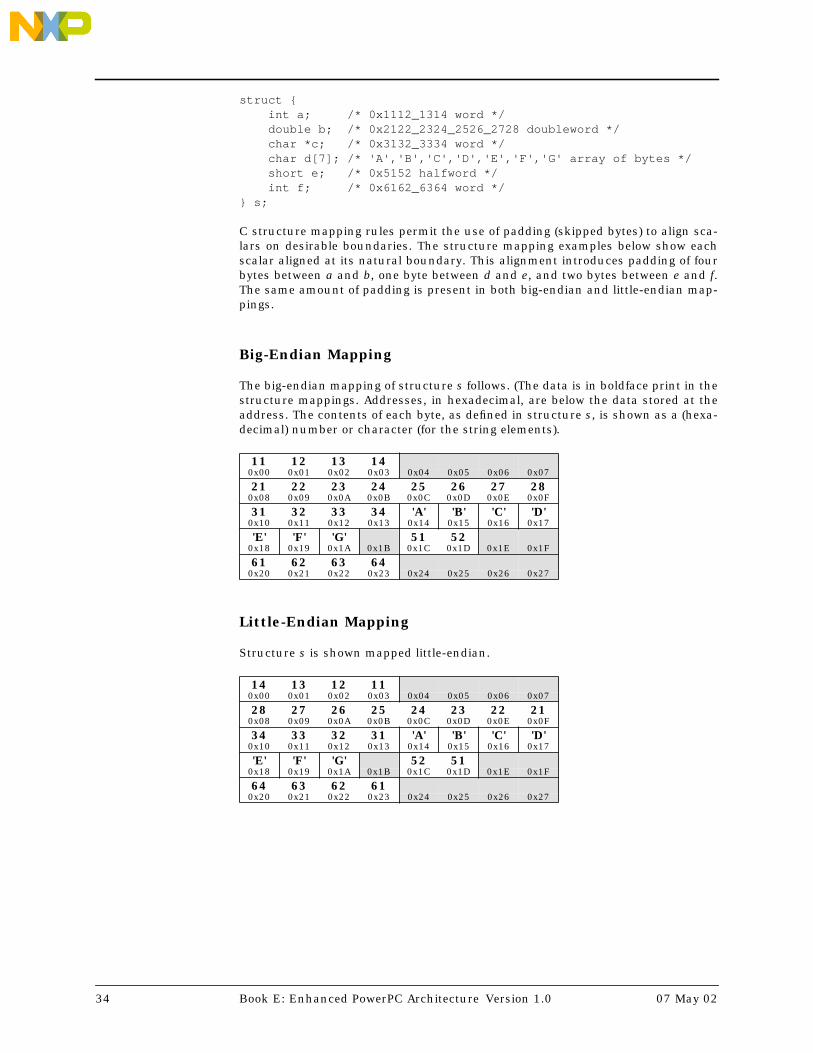
struct {int a; /* 0x1112_1314 word */double b; /* 0x2122_2324_2526_2728 doubleword */char *c; /* 0x3132_3334 word */char d[7]; /* 'A','B','C','D','E','F','G' array of bytes */short e; /* 0x5152 halfword */int f; /* 0x6162_6364 word */
} s;
C structure mapping rules permit the use of padding (skipped bytes) to align sca-lars on desirable boundaries. The structure mapping examples below show eachscalar aligned at its natural boundary. This alignment introduces padding of fourbytes between a and b, one byte between d and e, and two bytes between e and f.The same amount of padding is present in both big-endian and little-endian map-pings.
Big-Endian Mapping
The big-endian mapping of structure s follows. (The data is in boldface print in thestructure mappings. Addresses, in hexadecimal, are below the data stored at theaddress. The contents of each byte, as defined in structure s, is shown as a (hexa-decimal) number or character (for the string elements).
Little-Endian Mapping
Structure s is shown mapped little-endian.
11 12 13 140x00 0x01 0x02 0x03 0x04 0x05 0x06 0x07
21 22 23 24 25 26 27 280x08 0x09 0x0A 0x0B 0x0C 0x0D 0x0E 0x0F
31 32 33 34 'A' 'B' 'C' 'D'0x10 0x11 0x12 0x13 0x14 0x15 0x16 0x17
'E' 'F' 'G' 51 520x18 0x19 0x1A 0x1B 0x1C 0x1D 0x1E 0x1F
61 62 63 640x20 0x21 0x22 0x23 0x24 0x25 0x26 0x27
14 13 12 110x00 0x01 0x02 0x03 0x04 0x05 0x06 0x07
28 27 26 25 24 23 22 210x08 0x09 0x0A 0x0B 0x0C 0x0D 0x0E 0x0F
34 33 32 31 'A' 'B' 'C' 'D'0x10 0x11 0x12 0x13 0x14 0x15 0x16 0x17
'E' 'F' 'G' 52 510x18 0x19 0x1A 0x1B 0x1C 0x1D 0x1E 0x1F
64 63 62 610x20 0x21 0x22 0x23 0x24 0x25 0x26 0x27
34 Book E: Enhanced PowerPC Architecture Version 1.0 07 May 02

1.11.3.2 Instructions Byte Ordering
Book E defines instructions as aligned words (four bytes) in memory. As such,instructions in a big-endian program image are arranged with the most-signifi-cant byte (MSB) of the instruction word at the lowest numbered address.
Consider the big-endian mapping of instruction at address 0x00, where, forexample, p = add r7, r7, r4:
On the other hand, in a little-endian program the same instruction is arrangedwith the least-significant byte (LSB) of the instruction word at the lowest num-bered address:
When an instruction is fetched from memory, the instruction must be placed inthe pipeline with its bytes in the proper order. Otherwise, the instruction decodercannot recognize it. Book E numbers bits such that the most-significant byte ofan instruction is the byte containing bits 0:7 of the instruction, the next most-sig-nificant byte of an instruction is the byte containing bits 8:15 of the instruction,the next most-significant byte of an instruction is the byte containing bits 16:23 ofthe instruction, and the least-significant byte of an instruction is the byte con-taining bits 24:31 of the instruction, as depicted in the instruction format dia-grams (see Section 1.7, "Instruction Formats", on page 18). Given the difference inbyte order between the two endian formats, the processor must perform whateverbyte reversal is required (depending on the particular byte order in use) beforeattempting to execute the instruction. This reversal may occur between the mem-ory interface and an instruction cache, or between the cache and the instructiondecoder.
If storage is reprogrammed from one endian format to the other, the contents ofthe storage must be reloaded with program and data structures in the appropriateEndian format. If the contents of instruction memory change, the instructioncache must be made coherent with the updates. The instruction cache must beinvalidated and the updated memory contents must be fetched in the new Endianformat so that the proper byte ordering occurs in the event that this byte reversalis performed between the memory interface and the cache.
1.11.3.3 Data Byte Ordering
Unlike instruction fetches, data accesses cannot be byte-reversed between mem-ory and a data cache. Data byte ordering in memory depends on the data type(byte, halfword, word, or doubleword) of a specific data item. It is only when mov-ing a data item of a specific type from or to an architected register that it becomesknown whether byte reversal is required due to the Endian format of the dataitem. Therefore, byte reversal during load or store accesses is performed betweenmemory (or the data cache) and the architected register (e.g. GPR, FPR, etc.),depending on whether the load or store was a byte, halfword, word, or doublewordaccess.
Referring to the big-endian and little-endian mappings of structure s, as shown onpage 34, the differences between the byte locations of any data item in the struc-
MSB LSB
0x00 0x01 0x02 0x03
LSB MSB
0x00 0x01 0x02 0x03
07 May 02 Chapter 1 Introduction 35

ture depends upon the size of the particular data item. For example (again refer-ring to the big-endian and little-endian mappings of structure s):
• The word a has its four bytes reversed within the word spanning addresses0x00–0x03.
• The halfword e has its two bytes reversed within the halfword spanningaddresses 0x1C–0x1D.
Note that the array of bytes d, where each data item is a byte, is not reversedwhen the big-endian and little-endian mappings are compared. For example, thecharacter ‘A’ is located at address 0x14 in both the big-endian and little-endianmappings.
The size of the data item being loaded or stored must be known before the proces-sor can decide whether, and if so, how to reorder the bytes when moving thembetween a register and storage.
• For byte loads and stores, including strings, no reordering of bytes occurs.
• For halfword loads and stores, bytes may be reversed within the halfword,depending on the byte order.
• For word loads and stores, bytes may be reversed within the word, dependingon the byte order.
• For doubleword loads and stores, bytes may be reversed within the double-word, depending on the byte order.
Note that this mechanism applies, regardless of the alignment of data.
For example, when loading a data word from storage, all four bytes of the word areretrieved from memory (or the data cache) starting with the byte at the calculatedeffective address and continuing with the next three higher numbered bytes.Then, the bytes are placed in the register so that the byte from either the highestaddress or the lowest address is placed in the least-significant byte of the registerfor big-endian or little-endian storage, respectively.
1.11.3.4 Integer Load and Store Byte-Reverse Instructions
Book E provides a set of Load Byte-Reverse and Store Byte-Reverse instructionsthat access storage that is specified as being in one byte ordering in the samemanner that a non-byte-reverse Load or Store instruction would access storagethat is specified as being in the opposite byte ordering. For example, a Load Half-word Byte-Reverse Indexed instruction performs an halfword data storage accessfrom a big-endian storage location in the same manner as a Load HalfwordIndexed instruction performs an halfword data storage access from a little-endianstorage location, and vice-versa.
The function of the Load Byte-Reverse and Store Byte-Reverse instructions is use-ful when a particular page in storage contains some data written in big-endianordering and other data written in little-endian ordering. In such an environment,the Endianness storage attribute for the page would be set according to the pre-dominant byte ordering for the page, and ‘normal’, non-byte-reverse Load andStore instructions would be used to access data operands which used this pre-dominant byte ordering. Conversely, Load Byte-Reverse and Store Byte-Reverseinstructions would be used to access the data operands which used the other byteordering.
36 Book E: Enhanced PowerPC Architecture Version 1.0 07 May 02

1.11.3.5 Origin of Endian
The terms Big-Endian and Little-Endian come from Part I, Chapter 4, of JonathanSwift's Gulliver's Travels. Here is the complete passage, from the edition printed in1734 by George Faulkner in Dublin.
. . . our Histories of six Thousand Moons make no Mention of any otherRegions, than the two great Empires of Lilliput and Blefuscu. Which twomighty Powers have, as I was going to tell you, been engaged in a mostobstinate War for six and thirty Moons past. It began upon the followingOccasion. It is allowed on all Hands, that the primitive Way of breakingEggs before we eat them, was upon the larger End: But his presentMajesty's Grand-father, while he was a Boy, going to eat an Egg, andbreaking it according to the ancient Practice, happened to cut one of hisFingers. Whereupon the Emperor his Father, published an Edict,commanding all his Subjects, upon great Penalties, to break the smallerEnd of their Eggs. The People so highly resented this Law, that ourHistories tell us, there have been six Rebellions raised on that Account;wherein one Emperor lost his Life, and another his Crown. These civilCommotions were constantly fomented by the Monarchs of Blefuscu; andwhen they were quelled, the Exiles always fled for Refuge to that Empire.It is computed that eleven Thousand Persons have, at several Times,suffered Death, rather than submit to break their Eggs at the smaller End.Many hundred large Volumes have been published upon this Controversy:But the Books of the Big-Endians have been long forbidden, and the wholeParty rendered incapable by Law of holding Employments. During theCourse of these Troubles, the Emperors of Blefuscu did frequentlyexpostulate by their Ambassadors, accusing us of making a Schism inReligion, by offending against a fundamental Doctrine of our great ProphetLustrog, in the fifty-fourth Chapter of the Brundrecal, (which is theirAlcoran.) This, however, is thought to be a mere Strain upon the text: Forthe Words are these; That all true Believers shall break their Eggs at theconvenient End: and which is the convenient End, seems, in my humbleOpinion, to be left to every Man's Conscience, or at least in the Power of thechief Magistrate to determine. Now the Big-Endian Exiles have found somuch Credit in the Emperor of Blefuscu's Court; and so much privateAssistance and Encouragement from their Party here at home, that abloody War has been carried on between the two Empires for six andthirty Moons with various Success; during which Time we have lost FortyCapital Ships, and a much greater Number of smaller Vessels, togetherwith thirty thousand of our best Seamen and Soldiers; and the Damagereceived by the Enemy is reckoned to be somewhat greater than ours.However, they have now equipped a numerous Fleet, and are justpreparing to make a Descent upon us: and his Imperial Majesty, placinggreat Confidence in your Valour and Strength, hath commanded me to laythis Account of his Affairs before you.
07 May 02 Chapter 1 Introduction 37

1.12 Synchronization
The synchronization described in this section refers to the state of the processorthat is performing the synchronization.
1.12.1 Context Synchronization
An instruction or event is context synchronizing if it satisfies the requirementslisted below. Such instructions and events are collectively called context synchro-nizing operations. Examples of context synchronizing operations include the scinstruction, the rfi and rfci instructions, and most interrupts.
1. The operation is not initiated or, in the case of isync, does not complete, untilall instructions already in execution have completed to a point at which theyhave reported all exceptions they will cause.
2. The instructions that precede the operation complete execution in the context(privilege, address space, storage protection, etc.) in which they were initiated.
3. If the operation directly causes an interrupt (e.g., sc directly causes a SystemCall interrupt) or is an interrupt, the operation is not initiated until no inter-rupt-causing exception exists having higher priority than the exceptionassociated with the interrupt (see Section 7.9 on page 178).
4. The instructions that follow the operation will be fetched and executed in thecontext established by the operation as required by the sequential executionmodel. (This requirement dictates that any prefetched instructions be dis-carded and that any effects and side effects of executing them out-of-orderalso be discarded, except as described in Section 6.1.5 on page 112.)
A context synchronizing operation is necessarily execution synchronizing; seeSection 1.12.2. “Execution Synchronization”. Unlike the msync and mbarinstructions, a context synchronizing operation does not affect the order in whichstorage accesses are performed with respect to other processors and mechanisms.
1.12.2 Execution Synchronization
An instruction is execution synchronizing if it satisfies items 1 and 2 of the defini-tion of context synchronization (see Section 1.12.1). msync is treated like isyncwith respect to item 1 (i.e., the conditions described in item 1 apply to the comple-tion of msync). Examples of execution synchronizing instructions are msync,mtmsr, wrtee, and wrteei. Also, all context synchronizing instructions are execu-tion synchronizing.
Unlike a context synchronizing operation, an execution synchronizing instructionneed not ensure that the instructions following that instruction will execute in thecontext established by that instruction. This new context becomes effective some-time after the execution synchronizing instruction completes and before or at asubsequent context synchronizing operation.
38 Book E: Enhanced PowerPC Architecture Version 1.0 07 May 02
Chapter 2 Processor Control
2.1 Processor Control Registers
2.1.1 Machine State Register
The Machine State Register (MSR) is a 32-bit register. Machine State Register bitsare numbered 32 (most-significant bit) to 63 (least-significant bit). This registerdefines the state of the processor (i.e. enabling and disabling of interrupts anddebugging exceptions, selection of address space for instruction and data storageaccesses, and specifying whether the processor is in supervisor or user mode).
The Machine State Register contents are automatically saved, altered, andrestored by the interrupt-handling mechanism, as described in Section 7.5 onpage 151. If a non-critical interrupt is taken, the contents of the Machine StateRegister are automatically copied into Save/Restore Register 1. If a critical inter-rupt is taken, the contents of the Machine State Register are automatically copiedinto Critical Save/Restore Register 1. When an rfi or rfci is executed, the con-tents of the Machine State Register are restored from Save/Restore Register 1 orCritical Save/Restore Register 1, respectively.
The contents of the Machine State Register can be read into bits 32:63 of a GPRusing mfmsr RT, setting bits 0:31 of GPR(RT) to an undefined value. The contentsof bits 32:63 of GPR(RS) can be written to the Machine State Register using mtmsrRS. MSREE may be set or cleared atomically using wrtee or wrteei.
Table 2-1. Machine State Register Definition
Bit(s) Description
32:37 Reserved
38 Allocated for implementation-dependent use
39:44 Reserved
07 May 02 Chapter 2 Processor Control 39

45 Wait State Enable (WE)
=0 The processor is not in wait state and continues processing
=1 The processor enters the wait state by ceasing to execute instructions andentering low power mode. The details of how the wait state is entered andexited, and how the processor behaves while in the wait state, are imple-mentation-dependent. See the User’s Manual for the implementation forcomplete details.
46 Critical Enable (CE)
=0 Critical Input and Watchdog Timer interrupts are disabled
=1 Critical Input and Watchdog Timer interrupts are enabled
47 Preserved for PowerPC ILE
48 External Enable (EE)
=0 External Input, Decrementer, and Fixed-Interval Timer interrupts are dis-abled.
=1 External Input, Decrementer, and Fixed-Interval Timer interrupts are en-abled.
49 Problem State (PR)
=0 The processor is in supervisor mode, can execute any instruction, and canaccess any resource (e.g. GPRs, SPRs, MSR, etc.).
=1 The processor is in user mode, cannot execute any privileged instruction,and cannot access any privileged resource.
MSRPR also affects storage access control, as described in Section 6.2.4.
Editorial NoteThe term "problem state" is synonymous with the term "user mode".
50 Floating-Point Available (FP)
=0 The processor cannot execute any floating-point instructions, includingfloating-point loads, stores and moves.
=1 The processor can execute floating-point instructions.
51 Machine Check Enable (ME)
=0 Machine Check interrupts are disabled.
=1 Machine Check interrupts are enabled.
52 Floating-Point Exception Mode 0 (FE0) (See below)
53 Allocated for implementation-dependent use
54 Debug Interrupt Enable (DE)
=0 Debug interrupts are disabled
=1 Debug interrupts are enabled if DBCR0IDM=1
55 Floating-Point Exception Mode 1 (FE1) (See below)
56 Reserved
57 Preserved for PowerPC IP
58 Instruction Address Space (IS)
=0 The processor directs all instruction fetches to address space 0 (TS=0 inthe relevant TLB entry).
=1 The processor directs all instruction fetches to address space 1 (TS=1 inthe relevant TLB entry).
59 Data Address Space (DS)
=0 The processor directs all data storage accesses to address space 0 (TS=0 inthe relevant TLB entry).
=1 The processor directs all data storage accesses to address space 1 (TS=1 inthe relevant TLB entry).
60:61 Reserved
62 Preserved for PowerPC RI
63 Preserved for PowerPC LE
Programming NoteAn Machine State Register bit that is reserved may be altered by rfi/rfci.
Bit(s) Description
40 Book E: Enhanced PowerPC Architecture Version 1.0 07 May 02

The Floating-Point Exception Mode bits FE0 and FE1 are interpreted as shownbelow. For further details see Section 5.4 on page 81.
FE0 FE1 Mode0 0 Ignore Exceptions0 1 Imprecise Nonrecoverable1 0 Imprecise Recoverable1 1 Precise
2.1.2 Processor Identification Register
The Processor Identification Register (PIR) is a 32-bit register. Processor Identifica-tion Register bits are numbered 32 (most-significant bit) to 63 (least-significantbit). The Processor Identification Register contains a value that can be used to dis-tinguish the processor from other processors in the system.
The contents of the Processor Identification Register can be read into bits 32:63 ofGPR(RT) using mfspr RT,PIR, setting bits 0:31 of GPR(RT) to an undefined value.The means by which the Processor Identification Register is initialized are imple-mentation-dependent (see User’s Manual).
2.1.3 Processor Version Register
The Processor Version Register (PVR) is a 32-bit read-only register. Processor Ver-sion Register bits are numbered 32 (most-significant bit) to 63 (least-significantbit). The Processor Version Register contains a value identifying the version andrevision level of the processor.
The Processor Version Register distinguishes between processors that differ inattributes that may affect software. It contains two fields.
The contents of the Processor Version Register can be read into bits 32:63 ofGPR(RT) using mfspr RT,PVR, setting bits 0:31 of GPR(RT) to an undefined value.Write access to the Processor Version Register is not provided.
Table 2-2. Processor Version Register Definition
Version numbers are assigned by Book E process. Revision numbers are assignedby an implementation-defined process.
Bit(s) Description
32:47 VersionA 16-bit number that identifies the version of the processor. Different versionnumbers indicate major differences between processors, such as which optionalfacilities and instructions are supported.
48:63 RevisionA 16-bit number that distinguishes between implementations of the version. Dif-ferent revision numbers indicate minor differences between processors having thesame version number, such as clock rate and Engineering Change level.
07 May 02 Chapter 2 Processor Control 41

2.1.4 Software-Use Special Purpose Registers
Software-use Special Purpose Registers (SPRG0 through SPRG7, and USPRG0)that have no defined functionality.
SPRG0 through SPRG2These 64-bit registers can be accessed only in supervisor mode.
SPRG3This 64-bit register can be written only in supervisor mode. SPRG3 can beread in supervisor mode. It is implementation-dependent whether or notSPRG3 can be read in user mode. See the User Manual for theimplementation.
SPRG4 through SPRG7These 64-bit registers can be written only in supervisor mode. These registerscan be read in supervisor or user mode.
USPRG0This 64-bit register can be accessed in supervisor or user mode.
The contents of SPRGi can be read into GPR(RT) using mfspr RT,SPRGi. The con-tents of GPR(RS) can be written into SPRGi using mtspr SPRGi,RS.
The contents of USPRG0 can be read into GPR(RT) using mfspr RT,USPRG0. Thecontents of GPR(RS) can be written into USPRG0 using mtspr USPRG0,RS.
2.1.5 Device Control Registers
Device Control Registers (DCRs) are on-chip registers that exist architecturallyoutside the processor core and thus are not actually part of Book E. Book E sim-ply defines the existence of a Device Control Register ‘address space’ and theinstructions to access them and does not define any particular Device ControlRegisters themselves.
Engineering NoteAlthough the classification of a given difference between processors as ‘major’ or ‘minor’is somewhat arbitrary, the following are examples of differences that generally should beconsidered ‘major’.
• number and types of execution units• optional facilities and instructions supported• level of support of instructions (hard-wired or emulated)• size, geometry, and management of caches and of TLBs
The following are examples of differences that generally should be considered ‘minor’.
• remapping a processor to a new technology• redesigning a critical path to increase clock rate• fixing bugs
In general, any change to a processor should cause a new PVR value to be assigned.Even a seemingly trivial change that is not expected to be apparent to software shouldcause a new revision number to be assigned, in case the change is later discovered tohave introduced an error that software must circumvent.
42 Book E: Enhanced PowerPC Architecture Version 1.0 07 May 02

Device Control Registers may control the use of on-chip peripherals, such asmemory controllers (see the User’s Manual for specific Device Control Registerdefinitions).
The contents of Device Control Register DCRN can be read into GPR(RT) usingmfdcr RT,DCRN. The contents of GPR(RS) can be written into Device Control Reg-ister DCRN using mtdcr DCRN,RS.
2.2 Processor Control Instructions
2.2.1 System Linkage Instructions
sc, rfi, and rfci are system linkage instructions which enable the program to callupon the system to perform a service (i.e. invoke a System Call interrupt), and bywhich the system can return from performing a service or from processing aninterrupt. System linkage instructions are context synchronizing, as defined inSection 1.12.1 on page 38.
Table 2-3. System Linkage Instruction Set Index
2.2.2 Processor Control Register Manipulation Instruc-tions
Table 2-4. System Register Manipulation Instruction Set Index
2.2.3 Instruction Synchronization Instruction
Table 2-5. Instruction Synchronization Instruction Set Index
Mnemonic Instruction Pagesc System Call 334rfci Return From Critical Interrupt 325rfi Return From Interrupt 326
Mnemonic Instruction Pagemfdcr RT,DCRN Move From Device Control Register 307mfmsr RT Move From Machine State Register 308mfspr RT,SPRN Move From Special Purpose Register 309mtdcr DCRN,RS Move To Device Control Register 311mtmsr RS Move To Machine State Register 315mtspr SPRN,RS Move To Special Purpose Register 316wrtee RA Write MSR External Enable 368wrteei E Write MSR External Enable Immediate 368
Mnemonic Instruction Page
isync Instruction Synchronize 288
07 May 02 Chapter 2 Processor Control 43

2.2.4 Auxiliary Processing Query Instruction
Book E allows implementation-dependent extensions that enable processors tomore optimally address a specific application area or even a broad range of appli-cation areas. Extensions can range from a single instruction to a new class offunctionality (e.g. multimedia and 3-D graphics extensions).
Table 2-6. Auxiliary Processing Query Instruction Set Index
Mnemonic Instruction Pagemfapidi RT,RA Move From APID Indirect 307
44 Book E: Enhanced PowerPC Architecture Version 1.0 07 May 02

Chapter 3 Branch and Condition RegisterOperations
3.1 Branch Operations Overview
This section describes the registers and instructions that make up the branch andCondition Register operations facilities of Book E.
3.2 Registers for Branch Operations
3.2.1 Condition Register
The Condition Register (CR) is a 32-bit register. Condition Register bits are num-bered 32 (most-significant bit) to 63 (least-significant bit). The Condition Registerreflects the result of certain operations, and provides a mechanism for testing(and branching).
Figure 3-1. Condition Register
The bits in the Condition Register are grouped into eight 4-bit fields, named CRField 0 (CR0), CR Field 1 (CR1),..., and CR Field 7 (CR7), which are set in one ofthe following ways.
• Specified fields of the Condition Register can be set by a move to theCondition Register from a GPR (mtcrf).
CR0 CR1 CR2 CR3 CR4 CR5 CR6 CR7
32 36 40 44 48 52 56 60 63
07 May 02 Chapter 3 Branch and Condition Register Operations 45

• A specified field of the Condition Register can be set by a move to theCondition Register from another Condition Register field (mcrf), from the Inte-ger Exception Register (mcrxr), or from the Floating-Point Status and ControlRegister (mcrfs).
• CR Field 0 can be set as the implicit result of an integer instruction.
• CR Field 1 can be set as the implicit result of a floating-point instruction.
• A specified Condition Register field can be set as the result of either an inte-ger or a floating-point Compare instruction.
Instructions are provided to perform logical operations on individualCondition Register bits and to test individual Condition Register bits (seeSection 3.4 on page 52).
3.2.1.1 Condition Register setting for integer instructions
For all integer word instructions in which the Rc bit is defined and set to 1, andfor addic., andi., and andis., the first three bits of CR Field 0 (bits 32:34 of theCondition Register) are set by signed comparison of bits 32:63 of the result tozero, and the fourth bit of CR Field 0 (bit 35 of the Condition Register) is copiedfrom the final state of the SO bit of the Integer Exception Register. The Rc bit isnot defined for doubleword integer operations.
if (target_register) 32:63 < 0 then c ← 0b100else if (target_register) 32:63 > 0 then c ← 0b010else c ← 0b001CR0 ← c || XERSO
If any portion of the result is undefined, then the value placed into the first threebits of CR Field 0 is undefined.
The bits of CR Field 0 are interpreted as follows.
CR Bit Description
32 Negative (LT)Bit 32 of the result is equal to 1.
33 Positive (GT)Bit 32 of the result is equal to 0 and at least one of bits 33:63 of theresult is non-zero.
34 Zero (EQ)Bits 32:63 of the result are equal to 0.
35 Summary Overflow (SO)This is a copy of the final state of the SO bit of the Integer Exception Reg-ister at the completion of the instruction.
Programming NoteCR Field 0 may not reflect the ‘true’ (infinitely precise) result if overflow occurs: see Sec-tion 4.3.3, “Integer Arithmetic Instructions”, on page 59.
46 Book E: Enhanced PowerPC Architecture Version 1.0 07 May 02

3.2.1.2 Condition Register setting for store conditional instruc-tions
The Integer Store Conditional instructions stwcx., stwcxe., and stdcxe. also setCR Field 0. See instruction descriptions on page 342 and page 353 for a detaileddescription of how CR Field 0 is set.
3.2.1.3 Condition Register setting for floating-point instructions
For all floating-point instructions in which the Rc bit is defined and set to 1, CRField 1 (bits 36:39 of the Condition Register) is set to the Floating-Point exceptionstatus, copied from bits 32:35 of the Floating-Point Status and Control Register.These bits are interpreted as follows.
CR Bit Description
36 Floating-Point Exception Summary (FX)This is a copy of the final state of the FX bit of the Floating-Point Statusand Control Register at the completion of the instruction.
37 Floating-Point Enabled Exception Summary (FEX)This is a copy of the final state of the FEX bit of the Floating-Point Sta-tus and Control Register at the completion of the instruction.
38 Floating-Point Invalid Operation Exception Summary (VX)This is a copy of the final state of the VX bit of the Floating-Point Statusand Control Register at the completion of the instruction.
39 Floating-Point Overflow Exception (OX)This is a copy of the final state of the OX bit of the Floating-Point Statusand Control Register at the completion of the instruction.
3.2.1.4 Condition Register setting for compare instructions
For Compare instructions, a CR field specified by the BF field in the instruction isset to reflect the result of the comparison. The bits of CR Field BF are interpretedas follows. A complete description of how the bits are set is given in the instruc-tion descriptions in Section 4.3.5, “Integer Compare Instructions”, on page 62 andSection 5.6.6, “Floating-Point Compare Instructions”, on page 104.
CR Bit Description
4×BF + 32 Less Than, Floating-Point Less Than (LT, FL)For signed-integer Compare, GPR(RA) < SI or GPR(RB)For unsigned-integer Compare, GPR(RA) <u UI or GPR(RB)For floating-point Compare, FPR(FRA) <fp FPR(FRB).
4×BF + 33 Greater Than, Floating-Point Greater Than (GT, FG)For signed-integer Compare, GPR(RA) > SI or GPR(RB).For unsigned-integer Compare, GPR(RA) >u UI or GPR(RB).For floating-point Compare, FPR(FRA) >fp FPR(FRB).
4×BF + 34 Equal, Floating-Point Equal (EQ, FE)For integer Compare, GPR(RA) = SI, UI, or GPR(RB).For floating-point Compare, FPR(FRA) =fp FPR(FRB).
07 May 02 Chapter 3 Branch and Condition Register Operations 47

4×BF + 35 Summary Overflow, Floating-Point Unordered (SO, FU)For integer Compare, this is a copy of the final state of the SO bitof the Integer Exception Register at the completion of theinstruction.For floating-point Compare, one or both of FPR(FRA) andFPR(FRB) is a Not a Number.
3.2.2 Link Register
The Link Register (LR) is a 64-bit register. Link Register bits are numbered 0(most-significant bit) to 63 (least-significant bit). The Link Register can be used toprovide the branch target address for the Branch Conditional to Link Registerinstruction, and it holds the return address after Branch and Link instructions.
The contents of the Link Register can be read into a GPR using mfspr RT,LR. Thecontents of GPR(RS) can be written to the Link Register using mtspr LR,RS.
3.2.3 Count Register
The Count Register (CTR) is a 64-bit register. Count Register bits are numbered 0(most-significant bit) to 63 (least-significant bit). Bits 32:63 of the Count Registercan be used to hold a loop count that can be decremented during execution ofBranch instructions that contain an appropriately encoded BO field. If the value inbits 32:63 of the Count Register is 0 before being decremented, it is –1 afterwardand bits 0:31 are left unchanged. The entire 64-bit Count Register can also beused to provide the branch target address for the Branch Conditional to Count Reg-ister instruction.
The contents of the Count Register can be read into a GPR using mfspr RT,CTR.The contents of GPR(RS) can be written to the Count Register using mtspr CTR,RS.
48 Book E: Enhanced PowerPC Architecture Version 1.0 07 May 02

3.3 Branch Instructions
The sequence of instruction execution can be changed by the Branch instructions.Because all instructions are on word boundaries, bits 62 and 63 of the generatedbranch target address are considered to be 0 by the processor in performing thebranch.
The Branch instructions compute the effective address (EA) of the target in one ofthe following four ways, as described in Section 1.11.2.2, “Instruction StorageAddressing Modes”, on page 32.
1. Adding a displacement to the address of the Branch instruction (Branch orBranch Conditional with AA=0).
2. Specifying an absolute address (Branch or Branch Conditional with AA=1).
3. Using the address contained in the Link Register (Branch Conditional to LinkRegister).
4. Using the address contained in the Count Register (Branch Conditional toCount Register).
For the first two methods, the target addresses can be computed sufficientlyahead of the Branch instruction that instructions can be prefetched along the tar-get path. For the third and fourth methods, prefetching instructions along the tar-get path is also possible provided the Link Register or the Count Register is loadedsufficiently ahead of the Branch instruction.
Branching can be conditional or unconditional, and the return address canoptionally be provided. If the return address is to be provided (LK=1), the effectiveaddress of the instruction following the Branch instruction is placed into the LinkRegister after the branch target address has been computed: this is done whetheror not the branch is taken.
In Branch Conditional instructions, the BO field specifies the conditions underwhich the branch is taken. The first four bits of the BO field specify how thebranch is affected by or affects the Condition Register and the Count Register.The fifth bit, shown below as having the value ‘y’, may be used by some implemen-tations as described below.
The encoding for the BO field is as follows. If the BO field specifies that the CountRegister is to be decremented, bits 32:63 of the Count Register are decremented. Ifthe BO field specifies a condition that must be TRUE or FALSE, that condition isobtained from the contents of bit BI+321 of the Condition Register.
1. Note that bits in the Condition Register are numbered 32:63 and that ‘BI’ refers to the BI field in the Branchinstruction encoding. For example, specifying BI=2 refers to bit 34 of the Condition Register.
07 May 02 Chapter 3 Branch and Condition Register Operations 49

Table 3-1. BO Encodings
Above, ‘z’ denotes a bit that is ignored.
The ‘y’ bit provides a hint about whether a conditional branch is likely to be taken,and may be used by some implementations to improve performance.
The ‘branch always’ encoding of the BO field does not have a ‘y’ bit.
For Branch Conditional instructions that have a ‘y’ bit, using y=0 indicates thatthe following behavior is likely.
• If the instruction is bc, bcl, bca, bcla, bce, bcel, bcea, or bcela with a nega-tive value in the displacement field, the branch is taken.
• In all other cases (bc, bcl, bca, bcla, bce, bcel, bcea, or bcela with a nonneg-ative value in the displacement field, bclr, bclrl, bclre, bclrel, bcctr, bcctrl,bcctre, or bcctrel), the branch falls through (is not taken).
Using y=1 reverses the preceding indications.
The displacement field is used as described above even if the target is an absoluteaddress.
BO Description
0000y Decrement CTR32:63, then branch if the decremented CTR32:63≠0 andthe condition is FALSE.
0001y Decrement CTR32:63, then branch if the decremented CTR32:63=0 andthe condition is FALSE.
001zy Branch if the condition is FALSE.
0100y Decrement CTR32:63, then branch if the decremented CTR32:63≠0 andthe condition is TRUE.
0101y Decrement CTR32:63, then branch if the decremented CTR32:63=0 andthe condition is TRUE.
011zy Branch if the condition is TRUE.
1z00y Decrement CTR32:63, then branch if the decremented CTR32:63≠0.
1z01y Decrement CTR32:63, then branch if the decremented CTR32:63=0.
1z1zz Branch always.
Programming NoteThe ‘z’ bits should be set to 0, as they may be assigned a meaning in some future ver-sion of the architecture.
The default value for the ‘y’ bit should be 0: the value 1 should be used only if softwarehas determined that the prediction corresponding to y=1 is more likely to be correct thanthe prediction corresponding to y=0.
50 Book E: Enhanced PowerPC Architecture Version 1.0 07 May 02

Engineering NoteFor all three Branch Conditional instructions, the branch should be statically predictedto be taken if the value of the following expression is 1, and to fall through if the value is0.
(BO0 & BO2) | (s ⊕ BO4)
Here ‘s’ is bit 16 of the instruction, which is the sign bit of the displacement field if theinstruction has a displacement field and is 0 otherwise. BO4 is the ‘y’ bit, or a bit that isignored for the ‘branch always’ encoding of the BO field. (Advantage is taken of the factthat, for bclr, bclrl, bclre, bclrel, bcctr, bcctrl, bcctre, or bcctrel, bit 16 of the instruc-tion is part of a reserved field and therefore must be 0.)
Implementations should also consider dynamic, or run-time-driven branch predictiontechniques in addition to static branch prediction, where appropriate.
Programming NoteIn some implementations the processor may keep a stack of the Link Register valuesmost recently set by Branch and Link instructions, with the possible exception of theform shown below for obtaining the address of the next instruction. To benefit from thisstack, the following programming conventions should be used.
Let A, B, and Glue be programs.
• Obtaining the address of the next instruction:
Use the following form of Branch and Link.
bcl 20,31,$+4
• Loop counts:
Keep them in the Count Register, and use one of the Branch Conditional instructionsto decrement the count and to control branching (e.g., branching back to the start ofa loop if the decremented counter value is nonzero).
• Computed goto's, case statements, etc.:
Use the Count Register to hold the address to branch to, and use the bcctrinstruction (LK=0) to branch to the selected address.
• Direct subroutine linkage:
Here A calls B and B returns to A. The two branches should be as follows.
– A calls B: use a Branch instruction that sets the Link Register (LK=1).– B returns to A: use the bclr instruction (LK=0) (the return address is in, or can
be restored to, the Link Register).
• Indirect subroutine linkage:
Here A calls Glue, Glue calls B, and B returns to A rather than to Glue. (Such acalling sequence is common in linkage code used when the subroutine that theprogrammer wants to call, here B, is in a different module from the caller: the Binderinserts ‘glue’ code to mediate the branch.) The three branches should be as follows.
– A calls Glue: use a Branch instruction that sets the Link Register (LK=1).– Glue calls B: place the address of B into the Count Register, and use the bcctr
instruction (LK=0).– B returns to A: use the bclr instruction (LK=0) (the return address is in, or can
be restored to, the Link Register).
07 May 02 Chapter 3 Branch and Condition Register Operations 51

Table 3-2. Branch Instruction Set Index
3.4 Condition Register Instructions
Table 3-3. Condition Register Instruction Set Index
Mnemonic Instruction Pageb LIbl LIba LIbla LI
BranchBranch & LinkBranch AbsoluteBranch & Link Absolute
237
be LIbel LIbea LIbela LI
Branch ExtendedBranch Extended & LinkBranch Extended AbsoluteBranch Extended & Link Absolute
237
bc BO,BI,BDbcl BO,BI,BDbca BO,BI,BDbcla BO,BI,BD
Branch ConditionalBranch Conditional & LinkBranch Conditional AbsoluteBranch Conditional & Link Absolute
238
bce BO,BI,BDbcel BO,BI,BDbcea BO,BI,BDbcela BO,BI,BD
Branch Conditional ExtendedBranch Conditional Extended & LinkBranch Conditional Extended AbsoluteBranch Conditional Extended & Link Absolute
238
bclr BO,BIbclrl BO,BI
Branch Conditional to Link RegisterBranch Conditional to Link Register & Link
240
bclre BO,BIbclrel BO,BI
Branch Conditional to Link Register ExtendedBranch Conditional to Link Register Extended & Link
240
bcctr BO,BIbcctrl BO,BI
Branch Conditional to Count RegisterBranch Conditional to Count Register & Link
239
bcctre BO,BIbcctrel BO,BI
Branch Conditional to Count Register ExtendedBranch Conditional to Count Register Extended & Link
239
Mnemonic Instruction Pagecrand BT,BA,BB Condition Register AND 244crandc BT,BA,BB Condition Register AND with Complement 244creqv BT,BA,BB Condition Register Equivalent 244crnand BT,BA,BB Condition Register NAND 245crnor BT,BA,BB Condition Register NOR 245cror BT,BA,BB Condition Register OR 245crorc BT,BA,BB Condition Register OR with Complement 246crxor BT,BA,BB Condition Register XOR 246mcrf BF,BFA Move Condition Register Field 305mfcr RT Move From Condition Register 307mtcrf FXM,RS Move To Condition Register Fields 311
52 Book E: Enhanced PowerPC Architecture Version 1.0 07 May 02

Chapter 4 Integer Operations
4.1 Integer Operations Overview
This chapter describes the registers and instructions that make up the integeroperations. Section 4.2 describes the registers associated with the integer opera-tions. Section 4.3 describes the instructions associated with integer operations.
4.2 Registers for Integer Operations
4.2.1 General Purpose Registers
Implementations of this architecture provide 32 General Purpose Registers (GPRs)for integer operations. The instruction formats provide 5-bit fields for specifyingthe General Purpose Registers to be used in the execution of the instruction. TheGeneral Purpose Registers are numbered 0-31. Each General Purpose Register isa 64-bit register and can be used to contain address and integer data.
4.2.2 Integer Exception Register
The Integer Exception Register (XER) is a 64-bit register. Table 4-1 provides bitdefinitions for the Integer Exception Register.
Integer Exception Register bits are set based on the operation of an instructionconsidered as a whole, not on intermediate results (e.g., the Subtract From Carry-ing instruction, the result of which is specified as the sum of three values, setsbits in the Integer Exception Register based on the entire operation, not on anintermediate sum).
07 May 02 Chapter 4 Integer Operations 53

The contents of the Integer Exception Register can be read into a General PurposeRegister using mfspr RT,XER. The contents of a General Purpose Register can bewritten to the Integer Exception Register using mtspr XER,RS.
Table 4-1. Integer Exception Register Definition
Bit(s) Description
0 Summary Overflow 64 (SO64)The Summary Overflow 64 bit is set to 1 whenever an instruction (except mtspr) setsthe Overflow 64 bit to 1. Once set to 1, the SO64 bit remains set until it is clearedby an mtspr instruction (specifying the Integer Exception Register) or an mcrxr in-struction. The SO64 bit is not altered by Compare instructions, nor by other instruc-tions (except mtspr to the Integer Exception Register, and mcrxr64) that cannotoverflow. Executing an mtspr instruction to the Integer Exception Register, supply-ing the values 0 for SO64 and 1 for OV64, causes SO64 to be set to 0 and OV64 tobe set to 1.
1 Overflow 64 (OV64)The Overflow 64 bit is set to indicate that an overflow has occurred during executionof an instruction. X-form Add, Subtract From, and Negate instructions having OE=1set OV64 to 1 if the carry out of bit 0 is not equal to the carry out of bit 1, and setOV64 to 0 otherwise. This condition reflects a signed overflow. XO-form Multiply LowDoubleword and Divide Doubleword instructions having OE=1 set OV64 to 1 if theresult cannot be represented in 64 bits (mulld, divd, divdu), and set OV64 to 0 oth-erwise. The OV64 bit is not altered by Compare instructions, nor by other instruc-tions (except mtspr to the Integer Exception Register, and mcrxr64) that cannotoverflow.
2 Carry 64 (CA64)The Carry 64 bit is set as follows during execution of certain instructions. Add Car-rying, Subtract From Carrying, Add Extended, and Subtract From Extended instruc-tions set CA64 to 1 if there is a carry out of bit 0, and set CA64 to 0 otherwise. CA64can be used to indicate unsigned overflow for add and subtract operations that setCA64. Shift Right Algebraic Doubleword instructions set CA64 to 1 if any 1-bits havebeen shifted out of a negative operand, and set CA64 to 0 otherwise. The CA64 bitis not altered by Compare instructions, nor by other instructions (except Shift RightAlgebraic, mtspr to the Integer Exception Register, and mcrxr64) that cannot carry.
3:31 Reserved
32 Summary Overflow (SO)The Summary Overflow bit is set to 1 whenever an instruction (except mtspr) setsthe Overflow bit. Once set, the SO bit remains set until it is cleared by an mtspr in-struction (specifying the Integer Exception Register) or an mcrxr instruction. The SObit is not altered by Compare instructions, nor by other instructions (except mtsprto the Integer Exception Register, and mcrxr) that cannot overflow. Executing anmtspr instruction to the Integer Exception Register, supplying the values 0 for SOand 1 for OV, causes SO to be set to 0 and OV to be set to 1.
33 Overflow (OV)The Overflow bit is set to indicate that an overflow has occurred during execution ofan instruction. X-form Add, Subtract From, and Negate instructions having OE=1 setOV to 1 if the carry out of bit 32 is not equal to the carry out of bit 33, and set OVto 0 otherwise. This condition reflects a signed overflow. X-form Multiply Low Wordand Divide Word instructions having OE=1 set OV to 1 if the result cannot be repre-sented in 32 bits (mullw, divw, divwu), and set OV to 0 otherwise. The OV bit is notaltered by Compare instructions, nor by other instructions (except mtspr to the In-teger Exception Register, and mcrxr) that cannot overflow.
34 Carry (CA)The Carry bit is set as follows, during execution of certain instructions. Add Carry-ing, Subtract From Carrying, Add Extended, and Subtract From Extended instructionsset it to 1 if there is a carry out of bit 32, and set it to 0 otherwise. CA can be usedto indicate unsigned overflow for add and subtract operations that set CA. Shift RightAlgebraic Word instructions set CA to 1 if any 1-bits have been shifted out of a neg-ative operand, and set CA to 0 otherwise. The CA bit is not altered by Compare in-structions, nor by other instructions (except Shift Right Algebraic Word, mtspr to theInteger Exception Register, and mcrxr) that cannot carry.
54 Book E: Enhanced PowerPC Architecture Version 1.0 07 May 02

4.3 Integer Instructions
4.3.1 Integer Load Instructions
The Integer Load instructions compute the effective address (EA) of the storage tobe accessed as described in Section 1.11.2, “Effective Address Calculation”, onpage 31.
The byte, halfword, word, or doubleword in storage addressed by EA is loaded intoGPR(RT).
Many of the Integer Load instructions have an ‘update’ form, in which GPR(RA) isupdated with the effective address. For these forms, if RA≠0 and RA≠RT, the effec-tive address is placed into GPR(RA) and the storage element (byte, halfword, word,or doubleword) addressed by EA is loaded into GPR(RT). If RA=0 or RA=RT, theinstruction form is invalid.
Integer Load storage accesses will cause a Data Storage interrupt if the program isnot allowed to read the storage location. Integer Load storage accesses will cause aData TLB Error interrupt if the program attempts to access storage that isunavailable (.e. not currently mapped by the TLB).
Book E supports both Big-Endian and Little-Endian byte ordering.
Table 4-2. Basic Integer Load Instruction Set Index
35:56 Reserved
57:63 This field specifies the number of bytes to be transferred by a Load String Indexed orStore String Indexed instruction.
Programming NoteIn some implementations, the Load Halfword Algebraic and ‘with update’ Integer Loadinstructions may have greater latency than other types of Load instructions. Moreover,‘with update’ Integer Load instructions may take longer to execute in some implementa-tions than the corresponding pair of a non-update Load instruction and an Addinstruction.
Programming NoteThe DES field in DE-form Integer Load instructions is a word offset, not a byte offset likethe DE field in DE-form Integer Load instructions and D field in D-form Integer Loadinstructions. However, for programming convenience, assemblers should support thespecification of byte offsets for both forms of instruction.
Engineering NoteImplementations are strongly recommended to ignore bit 31 of instruction encodings forX-form Integer Load instructions.
Mnemonic Instruction Pagelbz RT,D(RA)lbzu RT,D(RA)
Load Byte and ZeroLoad Byte and Zero with Update
289
Bit(s) Description
07 May 02 Chapter 4 Integer Operations 55

Table 4-3. Integer Load Byte-Reverse Instruction Set Index
Table 4-4. Integer Load Multiple Instruction Set Index
Table 4-5. Integer Load String Instruction Set Index
lbze RT,DE(RA)lbzue RT,DE(RA)
Load Byte and Zero ExtendedLoad Byte and Zero with Update Extended
289
lbzx RT,RA,RBlbzux RT,RA,RB
Load Byte and Zero IndexedLoad Byte and Zero with Update Indexed
289
lbzxe RT,RA,RBlbzuxe RT,RA,RB
Load Byte and Zero Indexed ExtendedLoad Byte and Zero with Update Indexed Extended
289
lde RT,DES(RA)ldue RT,DES(RA)
Load Doubleword ExtendedLoad Doubleword with Update Extended
291
ldxe RT,RA,RBlduxe RT,RA,RB
Load Doubleword Indexed ExtendedLoad Doubleword with Update Indexed Extended
291
lha RT,D(RA)lhau RT,D(RA)
Load Halfword AlgebraicLoad Halfword Algebraic with Update
294
lhae RT,DE(RA)lhaue RT,DE(RA)
Load Halfword Algebraic ExtendedLoad Halfword Algebraic with Update Extended
294
lhax RT,RA,RBlhaux RT,RA,RB
Load Halfword Algebraic IndexedLoad Halfword Algebraic with Update Indexed
294
lhaxe RT,RA,RBlhauxe RT,RA,RB
Load Halfword Algebraic Indexed ExtendedLoad Halfword Algebraic with Update Indexed Extended
294
lhz RT,D(RA)lhzu RT,D(RA)
Load Halfword and ZeroLoad Halfword and Zero with Update
296
lhze RT,DE(RA)lhzue RT,DE(RA)
Load Halfword and Zero ExtendedLoad Halfword and Zero with Update Extended
296
lhzx RT,RA,RBlhzux RT,RA,RB
Load Halfword and Zero IndexedLoad Halfword and Zero with Update Indexed
296
lhzxe RT,RA,RBlhzuxe RT,RA,RB
Load Halfword and Zero Indexed ExtendedLoad Halfword and Zero with Update Indexed Extended
296
lwz RT,D(RA)lwzu RT,D(RA)
Load Word and ZeroLoad Word and Zero with Update
303
lwze RT,DE(RA)lwzue RT,DE(RA)
Load Word and Zero ExtendedLoad Word and Zero with Update Extended
303
lwzx RT,RA,RBlwzux RT,RA,RB
Load Word and Zero IndexedLoad Word and Zero with Update Indexed
303
lwzxe RT,RA,RBlwzuxe RT,RA,RB
Load Word and Zero Indexed ExtendedLoad Word and Zero with Update Indexed Extended
303
Mnemonic Instruction Pagelhbrx RT,RA,RB Load Halfword Byte-Reverse Indexed 295lhbrxe RT,RA,RB Load Halfword Byte-Reverse Indexed Extended 295lwbrx RT,RA,RB Load Word Byte-Reverse Indexed 302lwbrxe RT,RA,RB Load Word Byte-Reverse Indexed Extended 302When used in a Book E system operating with Big-Endian byte order, these instructions have the effectof loading data in Little-Endian order. Likewise, when used in a Book E system operating with Little-Endian byte order, these instructions have the effect of loading data in Big-Endian order.
Mnemonic Instruction Pagelmw RT,D(RA) Load Multiple Word 297
Mnemonic Instruction Pagelswi RT,RA,NB Load String Word Immediate 298lswx RT,RA,RB Load String Word Indexed 298The Integer Load String instructions, in combination with the Integer Store String instructions, allowmovement of data from storage to registers or from registers to storage without concern for alignment.These instructions can be used for a short move between arbitrary storage locations or to initiate a longmove between unaligned storage fields.
Mnemonic Instruction Page
56 Book E: Enhanced PowerPC Architecture Version 1.0 07 May 02

Table 4-6. Integer Load and Reserve Instruction Set Index
4.3.2 Integer Store Instructions
The Integer Store instructions compute the effective address (EA) of the storage tobe accessed as described in Section 1.11.2, “Effective Address Calculation”, onpage 31.
The contents of GPR(RS) are stored into the byte, halfword, word, or doublewordin storage addressed by EA.
Many of the Integer Store instructions have an ‘update’ form, in which GPR(RA) isupdated with the effective address. For these forms, the following rules apply.
• If RA≠0, the effective address is placed into GPR(RA).
• If RS=RA, the contents of GPR(RS) are copied to the target storage elementand then EA is placed into GPR(RA).
Integer Store storage accesses will cause a Data Storage interrupt if the program isnot allowed to write to the storage location. Integer Store storage accesses willcause a Data TLB Error interrupt if the program attempts to access storage that isunavailable.
Book E supports both Big-Endian and Little-Endian byte ordering.
Mnemonic Instruction Pageldarxe RT,RA,RB Load Doubleword And Reserve Indexed Extended 290lwarx RT,RA,RBlwarxe RT,RA,RB
Load Word And Reserve IndexedLoad Word And Reserve Indexed Extended
300
The Integer Load And Reserve instructions (lwarx, lwarxe, and ldarxe), in combination with the IntegerStore Conditional instructions (stwcx., stwcxe., and stdcxe.), permit the programmer to write asequence of instructions that appear to perform an atomic update operation on a storage location. Thisoperation depends upon a single reservation resource in each processor. At most one reservation existson any given processor: there are not separate reservations for words and for doublewords.Programming NoteBecause the Integer Load And Reserve instructions have implementation dependencies (e.g., the granu-larity at which reservations are managed), they must be used with care. The operating system shouldprovide system library programs that use these instructions to implement the high-level synchronizationfunctions (Test and Set, Compare and Swap, etc.) needed by application programs. Application pro-grams should use these library programs, rather than use the Integer Load And Reserve instructionsdirectly.Architecture NoteThe Integer Load And Reserve instructions require the EA to be aligned. Software should not attempt toemulate an unaligned Load And Reserve instruction, because there is no correct way to define theaddress associated with the reservation.Engineering NoteCausing an Alignment interrupt to be invoked if an attempt is made to execute a Load And Reserveinstruction having an incorrectly aligned effective address facilitates the debugging of software by signal-ling the exception when and where the exception occurs.Programming NoteThe granularity with which reservations are managed is implementation-dependent. Therefore the stor-age to be accessed by the Load And Reserve instructions should be allocated by a system library pro-gram. Additional information can be found in Section 6.1.6.2, “Atomic Update Primitives”, on page 117.
Programming NoteThe DES field in DE-form Integer Store instructions is a word offset, not a byte offset likethe DE field in DE-form Integer Store instructions and D field in D-form Integer Storeinstructions. However, for programming convenience, assemblers should support thespecification of byte offsets for both forms of instruction.
07 May 02 Chapter 4 Integer Operations 57

Table 4-7. Basic Integer Store Instruction Set Index
Table 4-8. Integer Store Byte-Reverse Instruction Set Index
Table 4-9. Integer Store Multiple Instruction Set Index
Table 4-10. Integer Store String Instruction Set Index
Engineering NoteImplementations are strongly recommended to ignore bit 31 of instruction encodings forX-form Integer Store instructions.
Mnemonic Instruction Pagestb RS,D(RA)stbu RS,D(RA)
Store ByteStore Byte with Update
341
stbe RS,DE(RA)stbue RS,DE(RA)
Store Byte ExtendedStore Byte with Update Extended
341
stbx RS,RA,RBstbux RS,RA,RB
Store Byte IndexedStore Byte with Update Indexed
341
stbxe RS,RA,RBstbuxe RS,RA,RB
Store Byte Indexed ExtendedStore Byte with Update Indexed Extended
341
stde RS,DES(RA)stdue RS,DES(RA)
Store Doubleword ExtendedStore Doubleword with Update Extended
343
stdxe RS,RA,RBstduxe RS,RA,RB
Store Doubleword Indexed ExtendedStore Doubleword with Update Indexed Extended
343
sth RS,D(RA)sthu RS,D(RA)
Store HalfwordStore Halfword with Update
347
sthe RS,DE(RA)sthue RS,DE(RA)
Store Halfword ExtendedStore Halfword with Update Extended
347
sthx RS,RA,RBsthux RS,RA,RB
Store Halfword IndexedStore Halfword with Update Indexed
347
sthxe RS,RA,RBsthuxe RS,RA,RB
Store Halfword Indexed ExtendedStore Halfword with Update Indexed Extended
347
stw RS,D(RA)stwu RS,D(RA)
Store WordStore Word with Update
351
stwe RS,DE(RA)stwue RS,DE(RA)
Store Word ExtendedStore Word with Update Extended
351
stwx RS,RA,RBstwux RS,RA,RB
Store Word IndexedStore Word with Update Indexed
351
stwxe RS,RA,RBstwuxe RS,RA,RB
Store Word Indexed ExtendedStore Word with Update Indexed Extended
351
Mnemonic Instruction Pagesthbrx RS,RA,RB Store Halfword Byte-Reverse Indexed 348sthbrxe RS,RA,RB Store Halfword Byte-Reverse Indexed Extended 348stwbrx RS,RA,RB Store Word Byte-Reverse Indexed 352stwbrxe RS,RA,RB Store Word Byte-Reverse Indexed Extended 352When used in a Book E system operating with Big-Endian byte order, these instructions have the effectof storing data in Little-Endian order. Likewise, when used in a Book E system operating with Little-Endian byte order, these instructions have the effect of storing data in Big-Endian order.
Mnemonic Instruction Pagestmw RS,D(RA) Store Multiple Word 349
Mnemonic Instruction Pagestswi RS,RA,NB Store String Word Immediate 350stswx RS,RA,RB Store String Word Indexed 350The Integer Store String instructions, in combination with the Integer Load String instructions, allowmovement of data from storage to registers or from registers to storage without concern for alignment.These instructions can be used for a short move between arbitrary storage locations or to initiate a longmove between unaligned storage fields.
58 Book E: Enhanced PowerPC Architecture Version 1.0 07 May 02

Table 4-11. Integer Store Conditional Instruction Set Index
4.3.3 Integer Arithmetic Instructions
The integer arithmetic instructions use the contents of the GPRs as source oper-ands, and place results into GPRs, into status bits in the Integer Exception Regis-ter, and into CR Field 0. addi and addis use the value 0, not the contents ofGPR(0), if RA=0.
The integer arithmetic instructions treat source operands as signed, two’s comple-ment integers unless the instruction is explicitly identified as performing anunsigned operation.
The X-form instructions with Rc=1, and the D-form instruction addic. set thefirst three bits of CR Field 0 to characterize bits 32:63 of the result that is placedin the target register. These bits are set by signed comparison of bits 32:63 of theresult to zero.
addic[.], subfic, addc[o][.], subfc[o][.], adde[o][.], subfe[o][.], addme[o][.], sub-fme[o][.], addze[o][.], and subfze[o][.] always set CA and CA64 to reflect the carryout of bit 32 and the carry out of bit 0, respectively.
The X-form Arithmetic instructions set SO and OV when OE=1 to reflect overflowof bits 32:63 of the result. X-form Arithmetic instructions also set SO64 and OV64when OE=1 to reflect overflow of bits 0:63 of the result.
Mnemonic Instruction Pagestdcxe. RS,RA,RB Store Doubleword Conditional Indexed Extended 342stwcx. RS,RA,RBstwcxe. RS,RA,RB
Store Word Conditional IndexedStore Word Conditional Indexed Extended
353
The Integer Store Conditional instructions (stwcx., stwcxe., and stdcxe.), in combination with the Inte-ger Load And Reserve instructions (lwarx, lwarxe, and ldarxe), permit the programmer to write asequence of instructions that appear to perform an atomic update operation on a storage location. Thisoperation depends upon a single reservation resource in each processor. At most one reservation existson any given processor: there are not separate reservations for words and for doublewords.Programming NoteBecause the Integer Store Conditional instructions have implementation dependencies (e.g., the granu-larity at which reservations are managed), they must be used with care. The operating system shouldprovide system library programs that use these instructions to implement the high-level synchronizationfunctions (Test and Set, Compare and Swap, etc.) needed by application programs. Application pro-grams should use these library programs, rather than use the Integer Store Conditional instructionsdirectly.Architecture NoteThe Integer Store Conditional instructions require the EA to be aligned. Software should not attempt toemulate an unaligned Integer Store Conditional instruction, because there is no correct way to define theaddress associated with the reservation.Engineering NoteCausing an Alignment interrupt to be invoked if an attempt is made to execute an Integer Store Condi-tional instruction having an incorrectly aligned effective address facilitates the debugging of software bysignalling the exception when and where the exception occurs.Programming NoteThe granularity with which reservations are managed is implementation-dependent. Therefore the stor-age to be accessed by the Integer Store Conditional instructions should be allocated by a system libraryprogram. Additional information can be found in Section 6.1.6.2, “Atomic Update Primitives”, onpage 117.
Programming NoteInstructions with the OE bit set or that set CA may execute slowly or may prevent theexecution of subsequent instructions until the instruction has completed.
07 May 02 Chapter 4 Integer Operations 59

For mulld, divd, and divdu, SO, OV and CA are not modified. For mullw, divw,and divwu, SO64, OV64 and CA64 are not affected.
Table 4-12. Integer Arithmetic Instruction Set Index
Programming NoteNotice that CR Field 0 may not reflect the ‘true’ (infinitely precise) result if overflowoccurs.
Programming Noteaddi, addis, add, and subf are the preferred instructions for addition and subtraction,because they set few status bits.
Mnemonic Instruction Pageadd RT,RA,RBadd. RT,RA,RBaddo RT,RA,RBaddo. RT,RA,RB
Add 229
addc RT,RA,RBaddc. RT,RA,RBaddco RT,RA,RBaddco. RT,RA,RB
Add Carrying 230
adde RT,RA,RBadde. RT,RA,RBaddeo RT,RA,RBaddeo. RT,RA,RBadde64 RT,RA,RBadde64o RT,RA,RB
Add Extended 231
addi RT,RA,SIaddis RT,RA,SI
Add ImmediateAdd Immediate Shifted
232
addic RT,RA,SIaddic. RT,RA,SI
Add Immediate Carrying 233
addme RT,RA,RBaddme. RT,RA,RBaddmeo RT,RA,RBaddmeo. RT,RA,RBaddme64 RT,RA,RBaddme64oRT,RA,RB
Add to Minus One Extended 234
addze RT,RA,RBaddze. RT,RA,RBaddzeo RT,RA,RBaddzeo. RT,RA,RBaddze64 RT,RA,RBaddze64o RT,RA,RB
Add to Zero Extended 235
divd RT,RA,RBdivdo RT,RA,RB
Divide Doubleword 255
divdu RT,RA,RBdivduo RT,RA,RB
Divide Doubleword Unsigned 256
divw RT,RA,RBdivw. RT,RA,RBdivwo RT,RA,RBdivwo. RT,RA,RB
Divide Word 257
divwu RT,RA,RBdivwu. RT,RA,RBdivwuo RT,RA,RBdivwuo. RT,RA,RB
Divide Word Unsigned 258
mulhd RT,RA,RB Multiply High Doubleword 317mulhdu RT,RA,RB Multiply High Doubleword Unsigned 317mulhw RT,RA,RBmulhw. RT,RA,RB
Multiply High Word 318
mulhwu RT,RA,RBmulhwu. RT,RA,RB
Multiply High Word Unsigned 318
mulld RT,RA,RBmulldo RT,RA,RB
Multiply Low Doubleword 319
mulli RT,RA,SI Multiply Low Immediate 319mullw RT,RA,RBmullw. RT,RA,RBmullwo RT,RA,RBmullwo. RT,RA,RB
Multiply Low Word 320
neg RT,RAneg. RT,RAnego RT,RAnego. RT,RA
Negate 322
60 Book E: Enhanced PowerPC Architecture Version 1.0 07 May 02

4.3.4 Integer Logical Instructions
The Logical instructions perform bit-parallel operations on 64-bit operands.
The X-form Logical instructions with Rc=1, and the D-form Logical instructionsandi. and andis. set the first three bits of CR Field 0 as described in Section4.3.3, “Integer Arithmetic Instructions”, on page 59. The Logical instructions donot change the SO, OV, CA, SO64, OV64 and CA64 bits in the Integer ExceptionRegister.
Table 4-13. Integer Logical Instruction Set Index
subf RT,RA,RBsubf. RT,RA,RBsubfo RT,RA,RBsubfo. RT,RA,RB
Subtract From 355
subfc RT,RA,RBsubfc. RT,RA,RBsubfco RT,RA,RBsubfco. RT,RA,RB
Subtract From Carrying 356
subfe RT,RA,RBsubfe. RT,RA,RBsubfeo RT,RA,RBsubfeo. RT,RA,RBsubfe64 RT,RA,RBsubfe64o RT,RA,RB
Subtract From Extended 357
subfic RT,RA,SI Subtract From Immediate Carrying 358subfme RT,RA,RBsubfme. RT,RA,RBsubfmeo RT,RA,RBsubfmeo. RT,RA,RBsubfme64 RT,RA,RBsubfme64oRT,RA,RB
Subtract From Minus One Extended 359
subfze RT,RA,RBsubfze. RT,RA,RBsubfzeo RT,RA,RBsubfzeo. RT,RA,RBsubfze64 RT,RA,RBsubfze64o RT,RA,RB
Subtract From Zero Extended 360
Mnemonic Instruction Pageand[.] RA,RS,RB AND 236andc[.] RA,RS,RB AND with Complement 236andi. RA,RS,UI AND Immediate 236andis. RA,RS,UI AND Immediate Shifted 236cntlzd RA,RS Count Leading Zeros Doubleword 243cntlzw RA,RScntlzw. RA,RS
Count Leading Zeros Word 243
eqv RA,RS,RBeqv. RA,RS,RB
Equivalent 259
extsb RA,RSextsb. RA,RS
Extend Sign Byte 260
extsh RA,RSextsh. RA,RS
Extend Sign Halfword 260
extsw RA,RS Extend Sign Word 260nand RA,RS,RBnand. RA,RS,RB
NAND 321
nor RA,RS,RBnor. RA,RS,RB
NOR 323
or RA,RS,RBor. RA,RS,RB
OR 324
orc RA,RS,RBorc. RA,RS,RB
OR with Complement 324
ori RA,RS,UI OR Immediate 324oris RA,RS,UI OR Immediate Shifted 324xor RA,RS,RBxor. RA,RS,RB
XOR 369
xori RA,RS,UI XOR Immediate 369
Mnemonic Instruction Page
07 May 02 Chapter 4 Integer Operations 61

4.3.5 Integer Compare Instructions
The integer Compare instructions compare the contents of GPR(RA) with (1) thesign-extended value of the SI field, (2) the zero-extended value of the UI field, or (3)the contents of GPR(RB). The comparison is signed for cmpi and cmp, andunsigned for cmpli and cmpl.
For 64-bit implementations, the L field controls whether the operands are treatedas 64-bit or 32-bit quantities, as follows:
L Operand length0 32-bit operands1 64-bit operands
When the operands are treated as 32-bit signed quantities, bit 32 of the register(RA or RB) is the sign bit.
For 32-bit implementations, the L field must be zero.
The Compare instructions set one bit in the left-most three bits of the designatedCR field to 1, and the other two to 0. The SO bit of the Integer Exception Registeris copied to bit 3 of the designated CR field.
The CR field is set as follows.
Bit Name Description
0 LT (RA) < SI or GPR(RB) (signed comparison)(RA) <u UI or GPR(RB) (unsigned comparison)
1 GT (RA) > SI or GPR(RB) (signed comparison)(RA) >u UI or GPR(RB) (unsigned comparison)
2 EQ (RA) = SI, UI, or GPR(RB)
3 SO Summary Overflow from the Integer Exception Register
Table 4-14. Integer Compare Instruction Set Index
4.3.6 Integer Trap Instructions
The Trap instructions are provided to test for a specified set of conditions fromcomparing the contents of one GPR with a second GPR or immediate data. If anyof the conditions tested by a Trap instruction are met, a Trap exception type Pro-
xoris RA,RS,UI XOR Immediate Shifted 369
Mnemonic Instruction Pagecmp BF,L,RA,RB Compare 241cmpi BF,L,RA,SI Compare Immediate 241cmpl BF,L,RA,RB Compare Logical 242cmpli BF,L,RA,SI Compare Logical Immediate 242
Mnemonic Instruction Page
62 Book E: Enhanced PowerPC Architecture Version 1.0 07 May 02

gram interrupt is invoked. If none of the tested conditions are met, instructionexecution continues normally.
The contents of GPR(RA) are compared with either the sign-extended value of theSI field or the contents of GPR(RB), depending on the Trap instruction. For tdiand td, the entire contents of RA (and RB) participate in the comparison; for twiand tw, only the contents of bits 32:63 of RA (and RB) participate in the compari-son.
This comparison results in five conditions which are ANDed with TO. If the resultis not 0 the Trap exception type Program interrupt is invoked. These conditionsare as follows.
TO Bit ANDed with Condition0 Less Than, using signed comparison1 Greater Than, using signed comparison2 Equal3 Less Than, using unsigned comparison4 Greater Than, using unsigned comparison
Table 4-15. Integer Compare Instruction Set Index
4.3.7 Integer Rotate and Shift Instructions
Instructions are provided that perform rotation operations on data from a GPRand return the result, or a portion of the result, to a GPR.
The rotation operations rotate a 64-bit quantity left by a specified number of bitpositions. Bits that exit from position 0 enter at position 63.
Two types of rotation operation are supported.
For the first type, denoted rotate64 or ROTL64, the value rotated is the given 64-bitvalue. The rotate64 operation is used to rotate a given 64-bit quantity.
For the second type, denoted rotate32 or ROTL32, the value rotated consists of twocopies of the given 32-bit value, one copy in bits 0:31 and the other in bits 32:63.The rotate32 operation is used to rotate a given 32-bit quantity employing the 64-bit rotator.
The Rotate and Shift instructions employ a mask generator. The mask is 64 bitslong, and consists of 1-bits from a start bit, mstart, through and including a stopbit, mstop, and 0-bits elsewhere. The values of mstart and mstop range from 0 to63. If mstart > mstop, the 1-bits wrap around from position 63 to position 0. Thusthe mask is formed as follows:
Mnemonic Instruction Pagetd TO,RA,RB Trap Doubleword 361tdi TO,RA,SI Trap Doubleword Immediate 361tw TO,RA,RB Trap Word 367twi TO,RA,SI Trap Word Immediate 367
07 May 02 Chapter 4 Integer Operations 63

if mstart ≤ mstop then mask mstart:mstop = ones mask all other bits = zeros else mask mstart:63 = ones mask 0:mstop = ones mask all other bits = zeros
There is no way to specify an all-zero mask.
For instructions that use the rotate32 operation, the mask start and stop positionsare always in bits 32:63 of the mask.
The use of the mask is described in following sections.
The Rotate Word and Shift Word instructions with Rc=1 set the first three bits ofCR field 0 as described in Section 4.3.3, “Integer Arithmetic Instructions”, onpage 59. Rotate and Shift instructions do not change the OV, OV64, SO, and SO64bits. Rotate and Shift instructions, except algebraic right shifts, do not change theCA or CA64 bits.
Table 4-16. Integer Rotate Instruction Set Index
Table 4-17. Integer Shift Instruction Set Index
Mnemonic Instruction Pagerldcl RA,RS,RB,MB Rotate Left Doubleword then Clear Left 327rldcr RA,RS,RB,ME Rotate Left Doubleword then Clear Right 328rldic RA,RS,SH,MB Rotate Left Doubleword Immediate then Clear 329rldicl RA,RS,SH,MB Rotate Left Doubleword Immediate then Clear Left 327rldicr RA,RS,SH,ME Rotate Left Doubleword Immediate then Clear Right 328rldimi RA,RS,SH,MB Rotate Left Doubleword Immediate then Mask Insert 330rlwimi RA,RS,SH,MB,MErlwimi. RA,RS,SH,MB,ME
Rotate Left Word Immediate then Mask Insert 331
rlwinm RA,RS,SH,MB,MErlwinm. RA,RS,SH,MB,ME
Rotate Left Word Immediate then AND with Mask 332
rlwnm RA,RS,RB,MB,MErlwnm. RA,RS,RB,MB,ME
Rotate Left Word then AND with Mask 332
These instructions rotate the contents of a register. Depending on the instruction type, the result of therotation is either
• inserted into the target register under control of a mask (if a mask bit is 1 the associated bit of therotated data is placed into the target register, and if the mask bit is 0 the associated bit in the tar-get register remains unchanged); or
• ANDed with a mask before being placed into the target register.
The Rotate Left instructions allow right-rotation of the contents of a register to be performed (in concept)by a left-rotation of 64-n, where n is the number of bits by which to rotate right. They allow right-rotationof the contents of bits 32:63 of a register to be performed (in concept) by a left-rotation of 32-n, where nis the number of bits by which to rotate right.Architecture NoteFor MD-form and MDS-form instructions, the MB and ME fields are used in permuted rather thansequential order because this is easier for the processor. Permuting the MB field permits the processorto obtain the low-order five bits of the MB value from the same place for all instructions having an MBfield (M-form and MD-form instructions). Permuting the ME field permits the processor to treat bits21:26 of all MD-form instructions uniformly.
Mnemonic Instruction Pagesld RA,RS,RB Shift Left Doubleword 335slw RA,RS,RBslw. RA,RS,RB
Shift Left Word 336
srad RA,RS,RB Shift Right Algebraic Doubleword 337sradi RA,RS,SH Shift Right Algebraic Doubleword Immediate 337sraw RA,RS,RBsraw. RA,RS,RB
Shift Right Algebraic Word 338
srawi RA,RS,SHsrawi. RA,RS,SH
Shift Right Algebraic Word Immediate 338
64 Book E: Enhanced PowerPC Architecture Version 1.0 07 May 02

4.3.8 Integer Exception Register Instructions
Table 4-18. Integer Exception Register Instruction Set Index
srd RA,RS,RB Shift Right Doubleword 339srw RA,RS,RBsrw. RA,RS,RB
Shift Right Word 340
Programming NoteAny Shift Right Algebraic instruction, followed by addze, can be used to divide quickly by 2n.Programming NoteMultiple-precision shifts can be programmed as shown in Section C.2, “Multiple-Precision Shifts”, onpage 387.Engineering NoteThe instructions intended for use with 32-bit data are shown as doing a rotate32 operation. This isstrictly necessary only for setting the CA bit for srawi and sraw. slw and srw could do a rotate64 oper-ation if that is easier.
Mnemonic Instruction Pagemcrxr BF Move to Condition Register from Integer Exception Register 306mcrxr64 BF Move to Condition Register from Integer Exception Register 64 306
Mnemonic Instruction Page
07 May 02 Chapter 4 Integer Operations 65

66 Book E: Enhanced PowerPC Architecture Version 1.0 07 May 02

Chapter 5 Floating-Point Operations
5.1 Overview
This chapter describes the registers and instructions that make up the floating-point operations. Section 5.2 on page 69 describes the registers associated withfloating-point operations. Section 5.6 on page 98 describes the instructions asso-ciated with floating-point operations.
This architecture specifies that the processor implement a floating-point systemas defined in ANSI/IEEE Standard 754-1985, ‘IEEE Standard for Binary Floating-Point Arithmetic’ (hereafter referred to as ‘the IEEE standard’), but requires soft-ware support in order to conform fully with that standard. That standard definescertain required ‘operations’ (addition, subtraction, etc.); the term ‘floating-pointoperation’ is used in this chapter to refer to one of these required operations, or tothe operation performed by one of the Multiply-Add or Reciprocal Estimate instruc-tions. All floating-point operations conform to that standard, except if softwaresets the Floating-Point Non-IEEE Mode (NI) bit in the Floating-Point Status andControl Register to 1 (see page 71), in which case floating-point operations do notnecessarily conform to that standard.
Instructions are provided to perform arithmetic, rounding, conversion, compari-son, and other operations in floating-point registers; to move floating-point databetween storage and these registers; and to manipulate the Floating-Point Statusand Control Register explicitly.
These instructions are divided into two categories.
• computational instructions
The computational instructions are those that perform addition, subtraction,multiplication, division, extracting the square root, rounding, conversion,comparison, and combinations of these operations. These instructions pro-vide the floating-point operations. They place status information into theFloating-Point Status and Control Register. They are the instructionsdescribed in Section 5.6.4, Section 5.6.5, and Section 5.6.6.
• non-computational instructions
07 May 02 Chapter 5 Floating-Point Operations 67

The non-computational instructions are those that perform loads and stores,move the contents of a floating-point register to another floating-point regis-ter possibly altering the sign, manipulate the Floating-Point Status andControl Register explicitly, and select the value from one of two floating-pointregisters based on the value in a third floating-point register. The operationsperformed by these instructions are not considered floating-point operations.With the exception of the instructions that manipulate the Floating-Point Sta-tus and Control Register explicitly, they do not alter the Floating-Point Statusand Control Register. They are the instructions described in Sections 5.6.1through 5.6.3, and 5.6.7.
A floating-point number consists of a signed exponent and a signed significand.The quantity expressed by this number is the product of the significand and thenumber 2exponent. Encodings are provided in the data format to represent finitenumeric values, ±Infinity, and values that are ‘Not a Number’ (NaN). Operationsinvolving infinities produce results obeying traditional mathematical conventions.NaNs have no mathematical interpretation. Their encoding permits a variablediagnostic information field. They may be used to indicate such things as unini-tialized variables and can be produced by certain invalid operations.
There is one class of exceptional events that occur during instruction executionthat is unique to floating-point operations: the Floating-Point Exception. Floating-point exceptions are signaled with bits set in the Floating-Point Status and Con-trol Register (FPSCR). They can cause an Enabled exception type Program inter-rupt to be taken, precisely or imprecisely, if the proper control bits are set.
Floating-Point Exceptions
The following floating-point exceptions are detected by the processor:
• Invalid Operation Exception (VX)
SNaN (VXSNAN)Infinity-Infinity (VXISI)Infinity÷Infinity (VXIDI)Zero÷Zero (VXZDZ)Infinity×Zero (VXIMZ)Invalid Compare (VXVC)Software Request (VXSOFT)Invalid Square Root (VXSQRT)Invalid Integer Convert (VXCVI)
• Zero Divide Exception (ZX)• Overflow Exception (OX)• Underflow Exception (UX)• Inexact Exception (XX)
Each floating-point exception, and each category of Invalid Operation Exception,has an exception bit in the Floating-Point Status and Control Register. In addi-tion, each floating-point exception has a corresponding enable bit in the Floating-Point Status and Control Register. See Section 5.2.2 on page 69 for a descriptionof these exception and enable bits, and Section 5.4 on page 81 for a detailed dis-cussion of floating-point exceptions, including the effects of the enable bits.
68 Book E: Enhanced PowerPC Architecture Version 1.0 07 May 02

5.2 Registers for Floating-Point Operations
5.2.1 Floating-Point Registers
Implementations of this architecture provide 32 Floating-Point Registers (FPRs).The floating-point instruction formats provide 5-bit fields for specifying the Float-ing-Point Registers to be used in the execution of the instruction. The Floating-Point Registers are numbered 0-31.
Each Floating-Point Register contains 64 bits that support the floating-point dou-ble format. Every instruction that interprets the contents of a Floating-Point Reg-ister as a floating-point value uses the floating-point double format for thisinterpretation.
The computational instructions, and the Move and Select instructions, operate ondata located in Floating-Point Registers and, with the exception of the Compareinstructions, place the result value into a Floating-Point Register and optionallyplace status information into the Condition Register.
Load and store double instructions are provided that transfer 64 bits of databetween storage and the Floating-Point Registers with no conversion. Load singleinstructions are provided to transfer and convert floating-point values in floating-point single format from storage to the same value in floating-point double formatin the Floating-Point Registers. Store single instructions are provided to transferand convert floating-point values in floating-point double format from the Float-ing-Point Registers to the same value in floating-point single format in storage.
Instructions are provided that manipulate the Floating-Point Status and ControlRegister and the Condition Register explicitly. Some of these instructions copydata from a Floating-Point Register to the Floating-Point Status and Control Reg-ister or vice versa.
The computational instructions and the Select instruction accept values from theFloating-Point Registers in double format. For single-precision arithmetic instruc-tions, all input values must be representable in single format; if they are not, theresult placed into the target Floating-Point Register, and the setting of status bitsin the Floating-Point Status and Control Register and in the Condition Register (ifRc=1), are undefined.
5.2.2 Floating-Point Status and Control Register
The Floating-Point Status and Control Register (FPSCR) controls the handling offloating-point exceptions and records status resulting from the floating-pointoperations. Bits 32:55 are status bits. Bits 56:63 are control bits.
The exception bits in the Floating-Point Status and Control Register (bits 35:45,53:55) are sticky; that is, once set to 1 they remain set to 1 until they are set to 0by an mcrfs, mtfsfi, mtfsf, or mtfsb0 instruction. The exception summary bitsin the Floating-Point Status and Control Register (FX, FEX, and VX, which arebits 32:34) are not considered to be ‘exception bits’, and only FX is sticky.
07 May 02 Chapter 5 Floating-Point Operations 69

FEX and VX are simply the OR of other Floating-Point Status and Control Registerbits. Therefore these two bits are not listed among the Floating-Point Status andControl Register bits affected by the various instructions.
Table 5-1. Floating-Point Status and Control Register Definition
Bit(s) Description
32 Floating-Point Exception Summary (FX)Every floating-point instruction, except mtfsfi and mtfsf, implicitly sets FPSCRFX to1 if that instruction causes any of the floating-point exception bits in the Floating-Point Status and Control Register to change from 0 to 1. mcrfs, mtfsfi, mtfsf,mtfsb0, and mtfsb1 can alter FPSCRFX explicitly.
33 Floating-Point Enabled Exception Summary (FEX)This bit is the OR of all the floating-point exception bits masked by their respectiveenable bits. mcrfs, mtfsfi, mtfsf, mtfsb0, and mtfsb1 cannot alter FPSCRFEX ex-plicitly.
34 Floating-Point Invalid Operation Exception Summary (VX)This bit is the OR of all the Invalid Operation exception bits. mcrfs, mtfsfi, mtfsf,mtfsb0, and mtfsb1 cannot alter FPSCRVX explicitly.
35 Floating-Point Overflow Exception (OX)See Section 5.4.3 on page 89.
36 Floating-Point Underflow Exception (UX)See Section 5.4.4 on page 91.
37 Floating-Point Zero Divide Exception (ZX)See Section 5.4.2 on page 88.
38 Floating-Point Inexact Exception (XX)See Section 5.4.5 on page 93.
FPSCRXX is a sticky version of FPSCRFI (see below). Thus the following rules com-pletely describe how FPSCRXX is set by a given instruction.
• If the instruction affects FPSCRFI, the new value of FPSCRXX is obtained by ORingthe old value of FPSCRXX with the new value of FPSCRFI.
• If the instruction does not affect FPSCRFI, the value of FPSCRXX is unchanged.
39 Floating-Point Invalid Operation Exception (SNaN) (VXSNAN)See Section 5.4.1 on page 85.
40 Floating-Point Invalid Operation Exception (∞-∞) (VXISI)See Section 5.4.1 on page 85.
41 Floating-Point Invalid Operation Exception (∞÷∞) (VXIDI)See Section 5.4.1 on page 85.
42 Floating-Point Invalid Operation Exception (0÷0) (VXZDZ)See Section 5.4.1 on page 85.
43 Floating-Point Invalid Operation Exception (∞×0) (VXIMZ)See Section 5.4.1 on page 85.
44 Floating-Point Invalid Operation Exception (Invalid Compare) (VXVC)See Section 5.4.1 on page 85.
45 Floating-Point Fraction Rounded (FR)The last Arithmetic or Rounding and Conversion instruction incremented the fractionduring rounding. See Section 5.3.6 on page 79. This bit is not sticky.
46 Floating-Point Fraction Inexact (FI)The last Arithmetic or Rounding and Conversion instruction either produced an inex-act result during rounding or caused a disabled Overflow Exception. SeeSection 5.3.6 on page 79. This bit is not sticky.
See the definition of FPSCRXX, above, regarding the relationship between FPSCRFIand FPSCRXX.
70 Book E: Enhanced PowerPC Architecture Version 1.0 07 May 02

47:51 Floating-Point Result Flags (FPRF)This field is set as described below. For arithmetic, rounding, and conversion instruc-tions, the field is set based on the result placed into the target register, except that ifany portion of the result is undefined then the value placed into FPRF is undefined.See Table 5-2 on page 72.
47 Floating-Point Result Class Descriptor (C)Arithmetic, rounding, and conversion instructions may set this bit with the FPCCbits, to indicate the class of the result.
48:51 Floating-Point Condition Code (FPCC)Floating-point Compare instructions set one of the FPCC bits to 1 and the other threeFPCC bits to 0. Arithmetic, rounding, and conversion instructions may set the FPCCbits with the C bit, to indicate the class of the result. Note that in this case the high-order three bits of the FPCC retain their relational significance indicating that the val-ue is less than, greater than, or equal to zero.
48 Floating-Point Less Than or Negative (FL or <)
49 Floating-Point Greater Than or Positive (FG or >)
50 Floating-Point Equal or Zero (FE or =)
51 Floating-Point Unordered or NaN (FU or ?)
52 Reserved
53 Floating-Point Invalid Operation Exception (Software Request) (VXSOFT)This bit can be altered only by mcrfs, mtfsfi, mtfsf, mtfsb0, or mtfsb1. SeeSection 5.4.1 on page 85.
54 Floating-Point Invalid Operation Exception (Invalid Square Root) (VXSQRT)See Section 5.4.1 on page 85.
Architecture NoteThis bit is defined even for implementations that do not support either of the two op-tional instructions that set it, namely Floating Square Root and Floating ReciprocalSquare Root Estimate. Defining it for all implementations gives software a standardinterface for handling square root exceptions.
Programming NoteIf the implementation does not support the optional Floating Square Root or FloatingReciprocal Square Root Estimate instruction, software can simulate the instructionand set this bit to reflect the exception.
55 Floating-Point Invalid Operation Exception (Invalid Integer Convert) (VXCVI)See Section 5.4.1 on page 85.
56 Floating-Point Invalid Operation Exception Enable (VE)See Section 5.4.1 on page 85.
57 Floating-Point Overflow Exception Enable (OE)See Section 5.4.1 on page 85.
58 Floating-Point Underflow Exception Enable (UE)See Section 5.4.1 on page 85.
59 Floating-Point Zero Divide Exception Enable (ZE)See Section 5.4.1 on page 85.
60 Floating-Point Inexact Exception Enable (XE)See Section 5.4.1 on page 85.
61 Floating-Point Non-IEEE Mode (NI)If this bit is set to 1, the remaining Floating-Point Status and Control Register bitsmay have meanings other than those given in this document, and the results of float-ing-point operations need not conform to the IEEE standard. If the IEEE-conformingresult of a floating-point operation would be a denormalized number, the result ofthat operation is 0 (with the same sign as the denormalized number) if FPSCRNI=1and other requirements specified in the User’s Manual for the implementation aremet. The other effects of setting this bit to 1 are described in the User’s Manual andmay differ between implementations.
Bit(s) Description
07 May 02 Chapter 5 Floating-Point Operations 71

Table 5-2. Floating-Point Result Flags
62:63 Floating-Point Rounding Control (RN)See Section 5.3.6 on page 79.
RN=00 Round to Nearest
RN=01 Round toward Zero
RN=10 Round toward +Infinity
RN=11 Round toward –Infinity
Result Flags Result Value Class
C < > = ?
100110100
011100000
000000111
000011000
110000001
Quiet NaN–Infinity–Normalized Number–Denormalized Number–Zero+Zero+Denormalized Number+Normalized Number+Infinity
Architecture NoteSetting Floating-Point Non-IEEE Mode (NI) to 1 is intended to permit results to beapproximate, and to cause performance to be more predictable and less data-dependentthan when NI=0. For example, in Non-IEEE Mode an implementation returns 0 insteadof a denormalized number, and may return a large number instead of an infinity. InNon-IEEE Mode an implementation should provide a means for ensuring that all resultsare produced without software assistance (i.e., without causing an Enabled exceptiontype Program interrupt or a Floating-Point Unimplemented Instruction exception typeProgram interrupt, and without invoking an ‘emulation assist’: see Chapter 7 onpage 143). The means may be controlled by one or more other Floating-Point Status andControl Register bits (recall that the other Floating-Point Status and Control Registerbits have implementation-dependent meanings when NI=1).
Bit(s) Description
72 Book E: Enhanced PowerPC Architecture Version 1.0 07 May 02

5.3 Floating-Point Data
5.3.1 Data Format
This architecture defines the representation of a floating-point value in two differ-ent binary fixed-length formats. The format may be a 32-bit single format for asingle-precision value or a 64-bit double format for a double-precision value. Thesingle format may be used for data in storage. The double format may be used fordata in storage and for data in floating-point registers.
The lengths of the exponent and the fraction fields differ between these two for-mats. The structure of the single and double formats is shown below.
Figure 5-1. Floating-point single format
Figure 5-2. Floating-point double format
Values in floating-point format are composed of three fields:
S sign bitEXP exponent+biasFRACTION fraction
If only a portion of a floating-point data item in storage is accessed, such as with aload or store instruction for a byte or halfword (or word in the case of floating-point double format), the value affected will depend on whether the Book E sys-tem is operating with Big-Endian byte order or Little-Endian byte order.
Representation of numeric values in the floating-point formats consists of a signbit (S), a biased exponent (EXP), and the fraction portion (FRACTION) of the signif-icand. The significand consists of a leading implied bit concatenated on the rightwith the FRACTION. This leading implied bit is 1 for normalized numbers and 0for denormalized numbers and is located in the unit bit position (i.e., the first bitto the left of the binary point). Values representable within the two floating-pointformats can be specified by the parameters listed in Table 5-3.
S EXP FRACTION0 1 9 31
S EXP FRACTION0 1 12 63
07 May 02 Chapter 5 Floating-Point Operations 73

Table 5-3. IEEE floating-point fields
The architecture requires that the Floating-Point Registers support the floating-point double format only.
5.3.2 Value Representation
This architecture defines numeric and non-numeric values representable withineach of the two supported formats. The numeric values are approximations to thereal numbers and include the normalized numbers, denormalized numbers, andzero values. The non-numeric values representable are the infinities and the Not aNumbers (NaNs). The infinities are adjoined to the real numbers, but are notnumbers themselves, and the standard rules of arithmetic do not hold when theyare used in an operation. They are related to the real numbers by order alone. It ispossible however to define restricted operations among numbers and infinities asdefined below. The relative location on the real number line for each of the definedentities is shown in Figure 5-3.
Figure 5-3. Approximation to real numbers
The NaNs are not related to the numeric values or infinities by order or value butare encodings used to convey diagnostic information such as the representation ofuninitialized variables.
The following is a description of the different floating-point values defined in thearchitecture:
Binary floating-point numbersMachine representable values used as approximations to real numbers. Threecategories of numbers are supported: normalized numbers, denormalized num-bers, and zero values.
Normalized numbers (±NOR)These are values that have an unbiased exponent value in the range:
–126 to 127 in single format–1022 to 1023 in double format
Single Double
Exponent Bias +127 +1023
Maximum Exponent +127 +1023
Minimum Exponent –126 –1022
Widths (bits)FormatSignExponentFractionSignificand
32182324
641115253
+0-0–DEN +DEN +NOR +INF–INF –NOR
74 Book E: Enhanced PowerPC Architecture Version 1.0 07 May 02

They are values in which the implied unit bit is 1. Normalized numbers are inter-preted as follows:
NOR = (-1)s x 2E x (1.fraction)
where s is the sign, E is the unbiased exponent, and 1.fraction is the significand,which is composed of a leading unit bit (implied bit) and a fraction part.
The ranges covered by the magnitude (M) of a normalized floating-point numberare approximately equal to:
Single Format:
1.2x10-38 ≤ M ≤ 3.4x1038
Double Format:
2.2x10-308 ≤ M ≤ 1.8x10308
Zero values (±0)These are values that have a biased exponent value of zero and a fraction value ofzero. Zeros can have a positive or negative sign. The sign of zero is ignored bycomparison operations (i.e., comparison regards +0 as equal to -0).
Denormalized numbers (±DEN)These are values that have a biased exponent value of zero and a nonzero fractionvalue. They are nonzero numbers smaller in magnitude than the representablenormalized numbers. They are values in which the implied unit bit is 0. Denor-malized numbers are interpreted as follows:
DEN = (-1)s x 2Emin x (0.fraction)
where Emin is the minimum representable exponent value (-126 for single-preci-sion, -1022 for double-precision).
Infinities (±∞)These are values that have the maximum biased exponent value:
255 in single format2047 in double format
and a zero fraction value. They are used to approximate values greater in magni-tude than the maximum normalized value.
Infinity arithmetic is defined as the limiting case of real arithmetic, with restrictedoperations defined among numbers and infinities. Infinities and the real numberscan be related by ordering in the affine sense:
-∞ < every finite number < +∞
Arithmetic on infinities is always exact and does not signal any exception, exceptwhen an exception occurs due to the invalid operations as described inSection 5.4.1 on page 85.
Not a Numbers (NaNs)These are values that have the maximum biased exponent value and a nonzerofraction value. The sign bit is ignored (i.e., NaNs are neither positive nor negative).If the high-order bit of the fraction field is 0 then the NaN is a Signalling NaN; oth-erwise it is a Quiet NaN.
07 May 02 Chapter 5 Floating-Point Operations 75

Signaling NaNs are used to signal exceptions when they appear as operands ofcomputational instructions.
Quiet NaNs are used to represent the results of certain invalid operations, such asinvalid arithmetic operations on infinities or on NaNs, when Invalid OperationException is disabled (FPSCRVE=0). Quiet NaNs propagate through all floating-point operations except comparison, Floating Round to Single-Precision, and con-version to integer. Quiet NaNs do not signal exceptions, except for ordered com-parison and conversion to integer operations. Specific encodings in QNaNs canthus be preserved through a sequence of floating-point operations, and used toconvey diagnostic information to help identify results from invalid operations.
When a QNaN is the result of a floating-point operation because one of the oper-ands is a NaN or because a QNaN was generated due to a disabled Invalid Opera-tion Exception, then the following rule is applied to determine the NaN with thehigh-order fraction bit set to 1 that is to be stored as the result.
if FPR(FRA) is a NaNthen FPR(FRT) ← FPR(FRA)else if FPR(FRB) is a NaN
then if instruction is frspthen FPR(FRT) ← FPR(FRB)0:34 || 290else FPR(FRT) ← FPR(FRB)
else if FPR(FRC) is a NaNthen FPR(FRT) ← FPR(FRC)else if generated QNaNthen FPR(FRT) ← generated QNaN
If the operand specified by FRA is a NaN, then that NaN is stored as the result.Otherwise, if the operand specified by FRB is a NaN (if the instruction specifies anFRB operand), then that NaN is stored as the result, with the low-order 29 bits ofthe result set to 0 if the instruction is frsp. Otherwise, if the operand specified byFRC is a NaN (if the instruction specifies an FRC operand), then that NaN isstored as the result. Otherwise, if a QNaN was generated due to a disabled InvalidOperation Exception, then that QNaN is stored as the result. If a QNaN is to begenerated as a result, then the QNaN generated has a sign bit of 0, an exponentfield of all 1s, and a high-order fraction bit of 1 with all other fraction bits 0. Anyinstruction that generates a QNaN as the result of a disabled Invalid Operationmust generate this QNaN (i.e., 0x7FF8_0000_0000_0000).
A double-precision NaN is representable in single format if and only if the low-order 29 bits of the double-precision NaNs fraction are zero.
5.3.3 Sign of Result
The following rules govern the sign of the result of an arithmetic, rounding, orconversion operation, when the operation does not yield an exception. They applyeven when the operands or results are zeros or infinities.
• The sign of the result of an add operation is the sign of the operand havingthe larger absolute value. If both operands have the same sign, the sign of theresult of an add operation is the same as the sign of the operands. The sign ofthe result of the subtract operation x-y is the same as the sign of the result ofthe add operation x+(-y).
When the sum of two operands with opposite sign, or the difference of twooperands with the same sign, is exactly zero, the sign of the result is positive
76 Book E: Enhanced PowerPC Architecture Version 1.0 07 May 02

in all rounding modes except Round toward -Infinity, in which mode the signis negative.
• The sign of the result of a multiply or divide operation is the Exclusive OR ofthe signs of the operands.
• The sign of the result of a Square Root or Reciprocal Square Root Estimateoperation is always positive, except that the square root of -0 is -0 and thereciprocal square root of -0 is -Infinity.
• The sign of the result of a Round to Single-Precision or Convert To/From Inte-ger operation is the sign of the operand being converted.
For the Multiply-Add instructions, the rules given above are applied first to themultiply operation and then to the add or subtract operation (one of the inputs tothe add or subtract operation is the result of the multiply operation).
5.3.4 Normalization and Denormalization
The intermediate result of an arithmetic or frsp instruction may require normal-ization and/or denormalization as described below. Normalization and denormal-ization do not affect the sign of the result.
When an arithmetic or frsp instruction produces an intermediate result, consist-ing of a sign bit, an exponent, and a nonzero significand with a 0 leading bit, it isnot a normalized number and must be normalized before it is stored.
A number is normalized by shifting its significand left while decrementing itsexponent by 1 for each bit shifted, until the leading significand bit becomes 1. TheGuard bit and the Round bit (see Section 5.5.1 on page 94) participate in the shiftwith zeros shifted into the Round bit. The exponent is regarded as if its range wereunlimited.
After normalization, or if normalization was not required, the intermediate resultmay have a nonzero significand and an exponent value that is less than the mini-mum value that can be represented in the format specified for the result. In thiscase, the intermediate result is said to be ‘Tiny’ and the stored result is deter-mined by the rules described in Section 5.4.4 on page 91. These rules may requiredenormalization.
A number is denormalized by shifting its significand right while incrementing itsexponent by 1 for each bit shifted, until the exponent is equal to the format's min-imum value. If any significant bits are lost in this shifting process then ‘Loss ofAccuracy’ has occurred (See Section 5.4.4 on page 91) and Underflow Exception issignaled.
Engineering NoteWhen denormalized numbers are operands of multiply, divide, and square root opera-tions, some implementations may prenormalize the operands internally beforeperforming the operations.
07 May 02 Chapter 5 Floating-Point Operations 77

5.3.5 Data Handling and Precision
Instructions are defined to move floating-point data between the Floating-PointRegisters and storage. For double format data, the data are not altered during themove. For single format data, a format conversion from single to double is per-formed when loading from storage into an Floating-Point Register and a formatconversion from double to single is performed when storing from an Floating-Point Register to storage. No floating-point exceptions are caused by theseinstructions.
All computational, Move, and Select instructions use the floating-point double for-mat.
Floating-point single-precision is obtained with the implementation of four typesof instruction.
1. Load Floating-Point Single
This form of instruction accesses a single-precision operand in single formatin storage, converts it to double format, and loads it into a Floating-Point Reg-ister. No floating-point exceptions are caused by these instructions.
2. Round to Floating-Point Single-Precision
The Floating Round to Single-Precision instruction rounds a double-precisionoperand to single-precision, checking the exponent for single-precision rangeand handling any exceptions according to respective enable bits, and placesthat operand into a Floating-Point Register as a double-precision operand. Forresults produced by single-precision arithmetic instructions, single-precisionloads, and other instances of the Floating Round to Single-Precision instruc-tion, this operation does not alter the value.
3. Single-Precision Arithmetic Instructions
This form of instruction takes operands from the Floating-Point Registers indouble format, performs the operation as if it produced an intermediate resulthaving infinite precision and unbounded exponent range, and then coercesthis intermediate result to fit in single format. Status bits, in the Floating-Point Status and Control Register and optionally in the Condition Register,are set to reflect the single-precision result. The result is then converted todouble format and placed into a Floating-Point Register. The result lies in therange supported by the single format.
All input values must be representable in single format; if they are not, theresult placed into the target Floating-Point Register, and the setting of statusbits in the Floating-Point Status and Control Register and in the ConditionRegister (if Rc=1), are undefined.
4. Store Floating-Point Single
This form of instruction converts a double-precision operand to single formatand stores that operand into storage. No floating-point exceptions are causedby these instructions. (The value being stored is effectively assumed to be theresult of an instruction of one of the preceding three types.)
78 Book E: Enhanced PowerPC Architecture Version 1.0 07 May 02

When the result of a Load Floating-Point Single, Floating Round to Single-Precision,or single-precision arithmetic instruction is stored in a Floating-Point Register,the low-order 29 FRACTION bits are zero.
5.3.6 Rounding
The material in this section applies to operations that have numeric operands(i.e., operands that are not infinities or NaNs). Rounding the intermediate result ofsuch an operation may cause an Overflow Exception, an Underflow Exception, oran Inexact Exception. The remainder of this section assumes that the operationcauses no exceptions and that the result is numeric. See Section 5.3.2 on page 74and Section 5.4 on page 81 for the cases not covered here.
The arithmetic, rounding, and conversion instructions produce an intermediateresult that can be regarded as having infinite precision and unbounded exponentrange. This intermediate result is normalized or denormalized if required, thenrounded to the destination format. The final result is then placed into the targetFloating-Point Register in double format or in integer format, depending on theinstruction.
The instructions that round their intermediate result are the Arithmetic andRounding and Conversion instructions. Each of these instructions sets Floating-Point Status and Control Register bits FR and FI. If the fraction was incrementedduring rounding then FR is set to 1, otherwise FR is set to 0. If the rounded resultis inexact then FI is set to 1, otherwise FI is set to 0.
The two Estimate instructions set FR and FI to undefined values. The remainingfloating-point instructions do not alter FR and FI.
Four user-selectable rounding modes are provided through the Floating-PointRounding Control field in the Floating-Point Status and Control Register. SeeSection 5.2.2 on page 69. These are encoded as follows:
Programming NoteThe Floating Round to Single-Precision instruction is provided to allow value conversionfrom double-precision to single-precision with appropriate exception checking androunding. This instruction should be used to convert double-precision floating-point val-ues (produced by double-precision load and arithmetic instructions and by fcfid) tosingle-precision values prior to storing them into single format storage elements or usingthem as operands for single-precision arithmetic instructions. Values produced by sin-gle-precision load and arithmetic instructions are already single-precision values andcan be stored directly into single format storage elements, or used directly as operandsfor single-precision arithmetic instructions, without preceding the store, or the arith-metic instruction, by a Floating Round to Single-Precision instruction.
Programming NoteA single-precision value can be used in double-precision arithmetic operations. Thereverse is true only if the double-precision value is representable in single format.
Some implementations may execute single-precision arithmetic instructions faster thandouble-precision arithmetic instructions. Therefore, if double-precision accuracy is notrequired, single-precision data and instructions should be used.
07 May 02 Chapter 5 Floating-Point Operations 79

RN Rounding Mode00 Round to Nearest01 Round toward Zero10 Round toward +Infinity11 Round toward -Infinity
Let Z be the intermediate arithmetic result or the operand of a convert operation.If Z can be represented exactly in the target format, then the result in all roundingmodes is Z as represented in the target format. If Z cannot be represented exactlyin the target format, let Z1 and Z2 bound Z as the next larger and next smallernumbers representable in the target format. Then Z1 or Z2 can be used to approx-imate the result in the target format.
Figure 5-4 shows the relation of Z, Z1, and Z2 in this case. The following rulesspecify the rounding in the four modes. ‘lsb’ means ‘least-significant bit’.
Figure 5-4. Selection of Z1 and Z2
Round to NearestChoose the value that is closer to Z (Z1 or Z2). In case of a tie, choose the onethat is even (least significant bit 0).
Round toward ZeroChoose the smaller in magnitude (Z1 or Z2).
Round toward +InfinityChoose Z1.
Round toward -InfinityChoose Z2.
See Section 5.5.1 on page 94 for a detailed explanation of rounding.
By Incrementing lsb of ZInfinitely Precise ValueBy Truncating after lsb
0Positive valuesNegative values
Z2 Z Z1Z2 Z Z1
80 Book E: Enhanced PowerPC Architecture Version 1.0 07 May 02

5.4 Floating-Point Exceptions
This architecture defines the following floating-point exceptions:
• Invalid Operation Exception
SNaNInfinity-InfinityInfinity÷InfinityZero÷ZeroInfinity×ZeroInvalid CompareSoftware RequestInvalid Square RootInvalid Integer Convert
• Zero Divide Exception• Overflow Exception• Underflow Exception• Inexact Exception
These exceptions may occur during execution of computational instructions. Inaddition, an Invalid Operation Exception occurs when a Move To Floating-PointStatus and Control Register instruction sets FPSCRVXSOFT to 1 (Software Request).
Each floating-point exception, and each category of Invalid Operation Exception,has an exception bit in the Floating-Point Status and Control Register. In addi-tion, each floating-point exception has a corresponding enable bit in the Floating-Point Status and Control Register. The exception bit indicates occurrence of thecorresponding exception. If an exception occurs, the corresponding enable bit gov-erns the result produced by the instruction and, in conjunction with the FE0 andFE1 bits (see page 82), whether and how the Enabled exception type Programinterrupt is taken. (In general, the enabling specified by the enable bit is of invok-ing the interrupt, not of permitting the exception to occur and the occurrence ofan exception depends only on the instruction and its inputs, not on the setting ofany control bits. The only deviations from this general rule are that the occur-rence of an Underflow Exception may depend on the setting of the UnderflowException enable bit , and the occurrence of an Inexact Exception may depend onthe setting of the Overflow Exception and Underflow Exception enable bits.)
A single instruction, other than mtfsfi or mtfsf, may set more than one exceptionbit only in the following cases:
• Inexact Exception may be set with Overflow Exception.
• Inexact Exception may be set with Underflow Exception.
• Invalid Operation Exception (SNaN) is set with Invalid Operation Exception(∞×0) for Multiply-Add instructions for which the values being multiplied areinfinity and zero and the value being added is an SNaN.
• Invalid Operation Exception (SNaN) may be set with Invalid Operation Excep-tion (Invalid Compare) for Compare Ordered instructions.
• Invalid Operation Exception (SNaN) may be set with Invalid Operation Excep-tion (Invalid Integer Convert) for Convert To Integer instructions.
07 May 02 Chapter 5 Floating-Point Operations 81

When an exception occurs the instruction execution may be suppressed or aresult may be delivered, depending on the exception.
Instruction execution is suppressed for the following kinds of exception, so thatthere is no possibility that one of the operands is lost:
• Enabled Invalid Operation• Enabled Zero Divide
For the remaining kinds of exception, a result is generated and written to the des-tination specified by the instruction causing the exception. The result may be adifferent value for the enabled and disabled conditions for some of these excep-tions. The kinds of exception that deliver a result are the following:
• Disabled Invalid Operation• Disabled Zero Divide• Disabled Overflow• Disabled Underflow• Disabled Inexact• Enabled Overflow• Enabled Underflow• Enabled Inexact
Subsequent sections define each of the floating-point exceptions and specify theaction that is taken when they are detected.
The IEEE standard specifies the handling of exceptional conditions in terms of‘traps’ and ‘trap handlers’. In this architecture, an Floating-Point Status and Con-trol Register exception enable bit of 1 causes generation of the result value speci-fied in the IEEE standard for the ‘trap enabled’ case: the expectation is that theexception will be detected by software, which will revise the result. An Floating-Point Status and Control Register exception enable bit of 0 causes generation ofthe ‘default result’ value specified for the ‘trap disabled’ (or ‘no trap occurs’ or ‘trapis not implemented’) case: the expectation is that the exception will not bedetected by software, which will simply use the default result. The result to bedelivered in each case for each exception is described in the sections below.
The IEEE default behavior when an exception occurs is to generate a default valueand not to notify software. In this architecture, if the IEEE default behavior whenan exception occurs is desired for all exceptions, all Floating-Point Status andControl Register exception enable bits should be set to 0 and Ignore ExceptionsMode (see below) should be used. In this case the Enabled exception type Programinterrupt is not taken, even if floating-point exceptions occur: software caninspect the Floating-Point Status and Control Register exception bits if necessary,to determine whether exceptions have occurred.
In this architecture, if software is to be notified that a given kind of exception hasoccurred, the corresponding Floating-Point Status and Control Register exceptionenable bit must be set to 1 and a mode other than Ignore Exceptions Mode mustbe used. In this case the Enabled exception type Program interrupt is taken if anenabled floating-point exception occurs. An Enabled exception type Programinterrupt is also taken if a Move To Floating-Point Status and Control Registerinstruction causes an exception bit and the corresponding enable bit both to be 1;the Move To Floating-Point Status and Control Register instruction is considered tocause the enabled exception.
The FE0 and FE1 bits control whether and how an Enabled exception type Pro-gram interrupt is taken if an enabled floating-point exception occurs. The locationof these bits and the requirements for altering them are described in Section 2.1.1on page 39. (An Enabled exception type Program interrupt is never taken because
82 Book E: Enhanced PowerPC Architecture Version 1.0 07 May 02

of a disabled floating-point exception.) The effects of the four possible settings ofthese bits are as follows.
In all cases, the question of whether a floating-point result is stored, and whatvalue is stored, is governed by the Floating-Point Status and Control Registerexception enable bits, as described in subsequent sections, and is not affected bythe value of the FE0 and FE1 bits.
In all cases in which an Enabled exception type Program interrupt is taken, allinstructions before the instruction at which the Enabled exception type Programinterrupt is taken have completed, and no instruction after the instruction atwhich the Enabled exception type Program interrupt is taken has begun execu-tion. (Recall that, for the two Imprecise modes, the instruction at which theEnabled exception type Program interrupt is taken need not be the instructionthat caused the exception.) The instruction at which the Enabled exception typeProgram interrupt is taken has not been executed unless it is the excepting
FE0 FE1 Description
0 0 Ignore Exceptions ModeFloating-point exceptions do not cause an Enabled exception typeProgram interrupt to be taken.
0 1 Imprecise Nonrecoverable ModeAn Enabled exception type Program interrupt is taken at somepoint at or beyond the instruction that caused the enabled excep-tion. It may not be possible to identify the excepting instruction orthe data that caused the exception. Results produced by theexcepting instruction may have been used by or may have affectedsubsequent instructions that are executed before the interrupt istaken.
1 0 Imprecise Recoverable ModeAn Enabled exception type Program interrupt is taken at somepoint at or beyond the instruction that caused the enabled excep-tion. Sufficient information is provided to the interrupt that it canidentify the excepting instruction and the operands, and correctthe result. No results produced by the excepting instruction havebeen used by or have affected subsequent instructions that areexecuted before the interrupt is taken.
1 1 Precise ModeAn Enabled exception type Program interrupt is taken precisely atthe instruction that caused the enabled exception.
Architecture NoteThe FE0 and FE1 bits of the Machine State Register are defined in Section 2.1.1 onpage 39 in a manner such that they can be changed dynamically and can easily betreated as part of a process' state.
07 May 02 Chapter 5 Floating-Point Operations 83

instruction, in which case it has been executed if the exception is not amongthose listed on page 82 as suppressed.
In order to obtain the best performance across the widest range of implementa-tions, the programmer should obey the following guidelines.
• If the IEEE default results are acceptable to the application, Ignore Excep-tions Mode should be used with all Floating-Point Status and Control Registerexception enable bits set to 0.
• If the IEEE default results are not acceptable to the application, ImpreciseNonrecoverable Mode should be used, or Imprecise Recoverable Mode if recov-erability is needed, with Floating-Point Status and Control Register exceptionenable bits set to 1 for those exceptions for which the Enabled exception typeProgram interrupt is to be taken.
• Ignore Exceptions Mode should not, in general, be used when any Floating-Point Status and Control Register exception enable bits are set to 1.
• Precise Mode may degrade performance in some implementations, perhapssubstantially, and therefore should be used only for debugging and other spe-cialized applications.
Programming NoteIn any of the three non-Precise modes, a Floating-Point Status and Control Registerinstruction can be used to force any exceptions, due to instructions initiated before theFloating-Point Status and Control Register instruction, to be recorded in the Floating-Point Status and Control Register. (This forcing is superfluous for Precise Mode.)
In either of the Imprecise modes, a Floating-Point Status and Control Register instructioncan be used to force any invocations of the Enabled exception type Program interrupt,due to instructions initiated before the Floating-Point Status and Control Register instruc-tion, to occur. (This forcing has no effect in Ignore Exceptions Mode, and is superfluousfor Precise Mode.)
A sync instruction, or any other execution synchronizing instruction or event (e.g.,isync), also has the effects described above. However, in order to obtain the best perfor-mance across the widest range of implementations, a Floating-Point Status and ControlRegister instruction should be used to obtain these effects.
Engineering NoteIt is permissible for the implementation to be precise in any of the three modes that per-mit interrupts, or to be recoverable in Nonrecoverable Mode.
84 Book E: Enhanced PowerPC Architecture Version 1.0 07 May 02

5.4.1 Invalid Operation Exception
Definition
An Invalid Operation Exception occurs when an operand is invalid for the speci-fied operation. The invalid operations are:
• Any floating-point operation on a signaling NaN (SNaN)
• For add or subtract operations, magnitude subtraction of infinities (∞-∞)
• Division of infinity by infinity (∞÷∞)
• Division of zero by zero (0÷0)
• Multiplication of infinity by zero (∞×0)
• Ordered comparison involving a NaN (Invalid Compare)
• Square root or reciprocal square root of a negative (and nonzero) number(Invalid Square Root)
• Integer convert involving a number too large in magnitude to be representedin the target format, or involving an infinity or a NaN (Invalid Integer Convert)
In addition, an Invalid Operation Exception occurs if software explicitly requeststhis by executing an mtfsfi, mtfsf, or mtfsb1 instruction that sets FPSCRVXSOFTto 1 (Software Request).
Action
The action to be taken depends on the setting of the Invalid Operation ExceptionEnable bit of the Floating-Point Status and Control Register.
When Invalid Operation Exception is enabled (FPSCRVE=1) and Invalid Operationoccurs or software explicitly requests the exception, the following actions aretaken:
1. One or two Invalid Operation Exceptions are setFPSCRVXSNAN (if SNaN)FPSCRVXISI (if ∞-∞)FPSCRVXIDI (if ∞÷∞)FPSCRVXZDZ (if 0÷0)FPSCRVXIMZ (if ∞×0)FPSCRVXVC (if invalid compare)FPSCRVXSOFT (if software request)FPSCRVXSQRT (if invalid square root)FPSCRVXCVI (if invalid integer convert)
2. If the operation is an arithmetic, Floating Round to Single-Precision, or convert
Programming NoteThe purpose of FPSCRVXSOFT is to allow software to cause an Invalid Operation Excep-tion for a condition that is not necessarily associated with the execution of a floating-point instruction. For example, it might be set by a program that computes a squareroot, if the source operand is negative.
07 May 02 Chapter 5 Floating-Point Operations 85

to integer operation,
the target Floating-Point Register is unchangedFPSCRFR FI are set to zeroFPSCRFPRF is unchanged
3. If the operation is a compare,
FPSCRFR FI C are unchangedFPSCRFPCC is set to reflect unordered
4. If software explicitly requests the exception,
FPSCRFR FI FPRF are as set by the mtfsfi, mtfsf, or mtfsb1 instruction
When Invalid Operation Exception is disabled (FPSCRVE=0) and Invalid Operationoccurs or software explicitly requests the exception, the following actions aretaken:
1. One or two Invalid Operation Exceptions are set
FPSCRVXSNAN (if SNaN)FPSCRVXISI (if ∞-∞)FPSCRVXIDI (if ∞÷∞)FPSCRVXZDZ (if 0÷0)FPSCRVXIMZ (if ∞×0)FPSCRVXVC (if invalid compare)FPSCRVXSOFT (if software request)FPSCRVXSQRT (if invalid square root)FPSCRVXCVI (if invalid integer convert)
2. If the operation is an arithmetic or Floating Round to Single-Precisionoperation,
the target Floating-Point Register is set to a Quiet NaNFPSCRFR FI are set to zeroFPSCRFPRF is set to indicate the class of the result (Quiet NaN)
3. If the operation is a convert to 64-bit integer operation,
the target Floating-Point Register is set as follows:
FPR(FRT) is set to the most positive 64-bit integer if the operand inFPR(FRB) is a positive number or +∞, and to the most negative 64-bitinteger if the operand in FPR(FRB) is a negative number, -∞, or NaN
FPSCRFR FI are set to zero
FPSCRFPRF is undefined
4. If the operation is a convert to 32-bit integer operation,
the target Floating-Point Register is set as follows:
FPR(FRT)0:31 ← undefined
86 Book E: Enhanced PowerPC Architecture Version 1.0 07 May 02

FPR(FRT)32:63 are set to the most positive 32-bit integer if the operandin FPR(FRB) is a positive number or +∞, and to the most negative 32-bitinteger if the operand in FPR(FRB) is a negative number, -∞, or NaN
FPSCRFR FI are set to zero
FPSCRFPRF is undefined
5. If the operation is a compare,
FPSCRFR FI C are unchangedFPSCRFPCC is set to reflect unordered
6. If software explicitly requests the exception,
FPSCRFR FI FPRF are as set by the mtfsfi, mtfsf, or mtfsb1 instruction
07 May 02 Chapter 5 Floating-Point Operations 87

5.4.2 Zero Divide Exception
Definition
A Zero Divide Exception occurs when a Divide instruction is executed with a zerodivisor value and a finite nonzero dividend value. It also occurs when a ReciprocalEstimate instruction (fres or frsqrte) is executed with an operand value of zero.
Action
The action to be taken depends on the setting of the Zero Divide Exception Enablebit of the Floating-Point Status and Control Register.
When Zero Divide Exception is enabled (FPSCRZE=1) and Zero Divide occurs, thefollowing actions are taken:
1. Zero Divide Exception is set
FPSCRZX ← 1
2. The target Floating-Point Register is unchanged
3. FPSCRFR FI are set to zero
4. FPSCRFPRF is unchanged
When Zero Divide Exception is disabled (FPSCRZE=0) and Zero Divide occurs, thefollowing actions are taken:
1. Zero Divide Exception is set
FPSCRZX ← 1
2. The target Floating-Point Register is set to ±Infinity, where the sign is deter-mined by the XOR of the signs of the operands
3. FPSCRFR FI are set to zero
4. FPSCRFPRF is set to indicate the class and sign of the result (±Infinity)
Architecture NoteThe name is a misnomer used for historical reasons. The proper name for this exceptionshould be ‘Exact Infinite Result from Finite Operands’ corresponding to what mathema-ticians call a ‘pole’.
88 Book E: Enhanced PowerPC Architecture Version 1.0 07 May 02

5.4.3 Overflow Exception
Definition
Overflow occurs when the magnitude of what would have been the rounded resultif the exponent range were unbounded exceeds that of the largest finite number ofthe specified result precision.
Action
The action to be taken depends on the setting of the Overflow Exception Enablebit of the Floating-Point Status and Control Register.
When Overflow Exception is enabled (FPSCROE=1) and exponent overflow occurs,the following actions are taken:
1. Overflow Exception is set
FPSCROX ← 1
2. For double-precision arithmetic instructions, the exponent of the normalizedintermediate result is adjusted by subtracting 1536
3. For single-precision arithmetic instructions and the Floating Round to Single-Precision instruction, the exponent of the normalized intermediate result isadjusted by subtracting 192
4. The adjusted rounded result is placed into the target Floating-Point Register
5. FPSCRFPRF is set to indicate the class and sign of the result (±NormalNumber)
When Overflow Exception is disabled (FPSCROE=0) and overflow occurs, the fol-lowing actions are taken:
1. Overflow Exception is set
FPSCROX ← 1
2. Inexact Exception is set
FPSCRXX ← 1
3. The result is determined by the rounding mode (FPSCRRN) and the sign of theintermediate result as follows:
A. Round to NearestStore ± Infinity, where the sign is the sign of the intermediate result
B. Round toward ZeroStore the format's largest finite number with the sign of the intermediateresult
C. Round toward +InfinityFor negative overflow, store the format's most negative finite number; forpositive overflow, store +Infinity
D. Round toward -Infinity
07 May 02 Chapter 5 Floating-Point Operations 89

For negative overflow, store -Infinity; for positive overflow, store theformat's largest finite number
4. The result is placed into the target Floating-Point Register
5. FPSCRFR is undefined
6. FPSCRFI is set to 1
7. FPSCRFPRF is set to indicate the class and sign of the result (±Infinity or ±Nor-mal Number)
90 Book E: Enhanced PowerPC Architecture Version 1.0 07 May 02

5.4.4 Underflow Exception
Definition
Underflow Exception is defined separately for the enabled and disabled states:
• Enabled:Underflow occurs when the intermediate result is ‘Tiny’.
• Disabled:Underflow occurs when the intermediate result is ‘Tiny’ and there is ‘Loss ofAccuracy’.
A ‘Tiny’ result is detected before rounding, when a nonzero intermediate resultcomputed as though both the precision and the exponent range were unboundedwould be less in magnitude than the smallest normalized number.
If the intermediate result is ‘Tiny’ and Underflow Exception is disabled(FPSCRUE=0) then the intermediate result is denormalized (see Section 5.3.4 onpage 77) and rounded (see Section 5.3.6 on page 79) before being placed into thetarget Floating-Point Register.
‘Loss of Accuracy’ is detected when the delivered result value differs from whatwould have been computed were both the precision and the exponent rangeunbounded.
Action
The action to be taken depends on the setting of the Underflow Exception Enablebit of the Floating-Point Status and Control Register.
When Underflow Exception is enabled (FPSCRUE=1) and exponent underflowoccurs, the following actions are taken:
1. Underflow Exception is set
FPSCRUX ← 1
2. For double-precision arithmetic instructions, the exponent of the normalizedintermediate result is adjusted by adding 1536
3. For single-precision arithmetic instructions and the Floating Round to Single-Precision instruction, the exponent of the normalized intermediate result isadjusted by adding 192
4. The adjusted rounded result is placed into the target Floating-Point Register
5. FPSCRFPRF is set to indicate the class and sign of the result (±NormalizedNumber)
When Underflow Exception is disabled (FPSCRUE=0) and underflow occurs, thefollowing actions are taken:
Programming NoteThe FR and FI bits are provided to allow the Enabled exception type Program interrupt,when taken because of an Underflow Exception, to simulate a ‘trap disabled’ environ-ment. That is, the FR and FI bits allow the Enabled exception type Program interrupt tounround the result, thus allowing the result to be denormalized.
07 May 02 Chapter 5 Floating-Point Operations 91

1. Underflow Exception is set
FPSCRUX ← 1
2. The rounded result is placed into the target Floating-Point Register
3. FPSCRFPRF is set to indicate the class and sign of the result (±NormalizedNumber, ±Denormalized Number, or ±Zero)
92 Book E: Enhanced PowerPC Architecture Version 1.0 07 May 02
5.4.5 Inexact Exception
Definition
An Inexact Exception occurs when one of two conditions occur during rounding:
1. The rounded result differs from the intermediate result assuming both theprecision and the exponent range of the intermediate result to be unbounded.In this case the result is said to be inexact. (If the rounding causes an enabledOverflow Exception or an enabled Underflow Exception, an Inexact Exceptionalso occurs only if the significands of the rounded result and the intermediateresult differ.)
2. The rounded result overflows and Overflow Exception is disabled.
Action
The action to be taken does not depend on the setting of the Inexact ExceptionEnable bit of the Floating-Point Status and Control Register.
When Inexact Exception occurs, the following actions are taken:
1. Inexact Exception is set
FPSCRXX ← 1
2. The rounded or overflowed result is placed into the target Floating-PointRegister
3. FPSCRFPRF is set to indicate the class and sign of the result
Programming NoteIn some implementations, enabling Inexact Exceptions may degrade performance morethan does enabling other types of floating-point exception.
07 May 02 Chapter 5 Floating-Point Operations 93

5.5 Floating-Point Execution Models
All implementations of this architecture must provide the equivalent of the follow-ing execution models to ensure that identical results are obtained.
Special rules are provided in the definition of the computational instructions forthe infinities, denormalized numbers and NaNs. The material in the remainder ofthis section applies to instructions that have numeric operands and a numericresult (i.e., operands and result that are not infinities or NaNs), and that cause noexceptions. See Section 5.3.2 on page 74 and Section 5.4 on page 81 for the casesnot covered here.
Although the double format specifies an 11-bit exponent, exponent arithmeticmakes use of two additional bits to avoid potential transient overflow conditions.One extra bit is required when denormalized double-precision numbers areprenormalized. The second bit is required to permit the computation of theadjusted exponent value in the following cases when the corresponding exceptionenable bit is 1:
• Underflow during multiplication using a denormalized operand.• Overflow during division using a denormalized divisor.
The IEEE standard includes 32-bit and 64-bit arithmetic. The standard requiresthat single-precision arithmetic be provided for single-precision operands. Thestandard permits double-precision floating-point operations to have either (orboth) single-precision or double-precision operands, but states that single-preci-sion floating-point operations should not accept double-precision operands.Book E follows these guidelines: double-precision arithmetic instructions canhave operands of either or both precisions, while single-precision arithmeticinstructions require all operands to be single-precision. Double-precision arith-metic instructions and fcfid produce double-precision values, while single-preci-sion arithmetic instructions produce single-precision values.
For arithmetic instructions, conversions from double-precision to single-precisionmust be done explicitly by software, while conversions from single-precision todouble-precision are done implicitly.
5.5.1 Execution Model for IEEE Operations
The following description uses 64-bit arithmetic as an example. 32-bit arithmeticis similar except that the FRACTION is a 23-bit field, and the single-precisionGuard, Round, and Sticky bits (described in this section) are logically adjacent tothe 23-bit FRACTION field.
IEEE-conforming significand arithmetic is considered to be performed with afloating-point accumulator having the following format, where bits 0:55 comprisethe significand of the intermediate result.
Figure 5-5. IEEE 64-bit execution model
The S bit is the sign bit.
S C L FRACTION G R X0 1 52 55
94 Book E: Enhanced PowerPC Architecture Version 1.0 07 May 02

The C bit is the carry bit, which captures the carry out of the significand.
The L bit is the leading unit bit of the significand, which receives the implicit bitfrom the operand.
The FRACTION is a 52-bit field that accepts the fraction of the operand.
The Guard (G), Round (R), and Sticky (X) bits are extensions to the low-order bitsof the accumulator. The G and R bits are required for post-normalization of theresult. The G, R, and X bits are required during rounding to determine if the inter-mediate result is equally near the two nearest representable values. The X bitserves as an extension to the G and R bits by representing the logical OR of allbits that may appear to the low-order side of the R bit, due either to shifting theaccumulator right or to other generation of low-order result bits. The G and R bitsparticipate in the left shifts with zeros being shifted into the R bit. Table 5-4shows the significance of the G, R, and X bits with respect to the intermediateresult (IR), the representable number next lower in magnitude (NL), and the repre-sentable number next higher in magnitude (NH).
Table 5-4. Interpretation of G, R, and X bits
After normalization, the intermediate result is rounded, using the rounding modespecified by FPSCRRN. If rounding results in a carry into C, the significand isshifted right one position and the exponent incremented by one. This yields aninexact result and possibly also exponent overflow. Fraction bits to the left of thebit position used for rounding are stored into the Floating-Point Register and low-order bit positions, if any, are set to zero.
Four user-selectable rounding modes are provided through FPSCRRN as describedin Section 5.3.6 on page 79. For rounding, the conceptual Guard, Round, andSticky bits are defined in terms of accumulator bits. Table 5-5 shows the posi-tions of the Guard, Round, and Sticky bits for double-precision and single-preci-sion floating-point numbers in the IEEE execution model.
Table 5-5. Location of the Guard, Round, and Sticky bits in the IEEE execution model
Rounding can be treated as though the significand were shifted right, if required,until the least significant bit to be retained is in the low-order bit position of theFRACTION. If any of the Guard, Round, or Sticky bits is nonzero, then the resultis inexact.
Z1 and Z2, as defined on page 80, can be used to approximate the result in thetarget format when one of the following rules is used.
G R X Interpretation
0 0 0 IR is exact
000
011
101
IR closer to NL
1 0 0 IR midway between NL and NH
111
011
101
IR closer to NH
Format Guard Round Sticky
DoubleSingle
G bit24
R bit25
X bitOR of 26:52, G, R, X
07 May 02 Chapter 5 Floating-Point Operations 95

• Round to Nearest
Guard bit = 0The result is truncated. (Result exact (GRX = 000) or closest to next lowervalue in magnitude (GRX = 001, 010, or 011))
Guard bit = 1Depends on Round and Sticky bits:
Case aIf the Round or Sticky bit is 1 (inclusive), the result is incremented.(Result closest to next higher value in magnitude (GRX = 101, 110, or111))
Case bIf the Round and Sticky bits are 0 (result midway between closest rep-resentable values), then if the low-order bit of the result is 1 the resultis incremented. Otherwise (the low-order bit of the result is 0) theresult is truncated (this is the case of a tie rounded to even).
• Round toward ZeroChoose the smaller in magnitude of Z1 or Z2. If the Guard, Round, or Stickybit is nonzero, the result is inexact.
• Round toward +InfinityChoose Z1.
• Round toward -InfinityChoose Z2.
Where the result is to have fewer than 53 bits of precision because the instructionis a Floating Round to Single-Precision or single-precision arithmetic instruction,the intermediate result is either normalized or placed in correct denormalizedform before being rounded.
5.5.2 Execution Model for Multiply-Add TypeInstructions
Book E provides a special form of instruction that performs up to three operationsin one instruction (a multiplication, an addition, and a negation). With this addedcapability comes the special ability to produce a more exact intermediate result asinput to the rounder. 32-bit arithmetic is similar except that the FRACTION fieldis smaller.
Multiply-add significand arithmetic is considered to be performed with a floating-point accumulator having the following format, where bits 0:106 comprise the sig-nificand of the intermediate result.
Figure 5-6. Multiply-Add 64-bit execution model
The first part of the operation is a multiplication. The multiplication has two 53-bit significands as inputs, which are assumed to be prenormalized, and producesa result conforming to the above model. If there is a carry out of the significand(into the C bit), then the significand is shifted right one position, shifting the L bit
S C L FRACTION X’0 1 105106
96 Book E: Enhanced PowerPC Architecture Version 1.0 07 May 02

(leading unit bit) into the most significant bit of the FRACTION and shifting the Cbit (carry out) into the L bit. All 106 bits (L bit, the FRACTION) of the product takepart in the add operation. If the exponents of the two inputs to the adder are notequal, the significand of the operand with the smaller exponent is aligned (shifted)to the right by an amount that is added to that exponent to make it equal to theother input's exponent. Zeros are shifted into the left of the significand as it isaligned and bits shifted out of bit 105 of the significand are ORed into the X' bit.The add operation also produces a result conforming to the above model with theX' bit taking part in the add operation.
The result of the addition is then normalized, with all bits of the addition result,except the X' bit, participating in the shift. The normalized result serves as theintermediate result that is input to the rounder.
For rounding, the conceptual Guard, Round, and Sticky bits are defined in termsof accumulator bits. Table 5-6 shows the positions of the Guard, Round, andSticky bits for double-precision and single-precision floating-point numbers in themultiply-add execution model.
Table 5-6. Location of the Guard, Round, and Sticky bits in the multiply-add executionmodel
The rules for rounding the intermediate result are the same as those given inSection 5.5.1 on page 94.
If the instruction is Floating Negative Multiply-Add or Floating Negative Multiply-Subtract, the final result is negated.
Format Guard Round Sticky
DoubleSingle
5324
5425
OR of 55:105, X'OR of 26:105, X'
07 May 02 Chapter 5 Floating-Point Operations 97

5.6 Floating-Point Instructions
5.6.1 Floating-Point Load Instructions
There are two basic forms of load instruction: single-precision and double-preci-sion. Because the FPRs support only floating-point double format, single-preci-sion Load Floating-Point instructions convert single-precision data to doubleformat prior to loading the operand into the target Floating-Point Register. Theconversion and loading steps are as follows.
Let WORD0:31 be the floating-point single-precision operand accessed from stor-age.
Architecture NoteThe rules followed in assigning new primary and extended opcodes.
1. Primary opcode 63 is used for the double-precision arithmetic instructions as well asmiscellaneous instructions (e.g. Floating-Point Status and Control RegisterManipulation instructions). Primary opcode 59 is used for the single-precisionarithmetic instructions.
2. The single-precision instructions for which there is a corresponding double-precisioninstruction have the same format and extended opcode as that double-precisioninstruction.
3. In assigning new extended opcodes for primary opcode 63, the following regularitiesare maintained. In addition, all new X-form instructions in primary opcode 63 havebits 21:22 = 0b11.
• Bit 26 = 1 iff the instruction is A-form.
• Bits 26:29 = 0b0000 iff the instruction is a comparison or mcrfs (i.e., iff theinstruction sets an explicitly-designated CR field).
• Bits 26:28 = 0b001 iff the instruction explicitly refers to or sets the Floating-Point Status and Control Register (i.e., is a Floating-Point Status and ControlRegister instruction) and is not mcrfs.
• Bits 26:30 = 0b01000 iff the instruction is a Move Register instruction, or anyother instruction that does not refer to or set the Floating-Point Status andControl Register.
4. In assigning extended opcodes for primary opcode 59, the following regularities havebeen maintained. They are based on those rules for primary opcode 63 that apply tothe instructions having primary opcode 59. In particular, primary opcode 59 has noFloating-Point Status and Control Register instructions, so the corresponding ruledoes not apply.
• If there is a corresponding instruction with primary opcode 63, its extendedopcode is used.
• Bit 26 = 1 iff the instruction is A-form.
• Bits 26:30 = 0b01000 iff the instruction is a Move Register instruction, or anyother instruction that does not refer to or set the Floating-Point Status andControl Register.
98 Book E: Enhanced PowerPC Architecture Version 1.0 07 May 02

Normalized Operand if WORD1:8 > 0 and WORD1:8 < 255 then
FPR(FRT)0:1 ← WORD0:1FPR(FRT)2 ← ¬WORD1FPR(FRT)3 ← ¬WORD1FPR(FRT)4 ← ¬WORD1FPR(FRT)5:63 ← WORD2:31 || 290
Denormalized Operandif WORD1:8 = 0 and WORD9:31 ≠ 0 then
sign ← WORD0exp ← -126frac0:52 ← 0b0 || WORD9:31 || 290normalize the operand
do while frac0 = 0frac ← frac1:52 || 0b0exp ← exp - 1
FPR(FRT)0 ← signFPR(FRT)1:11 ← exp + 1023FPR(FRT)12:63 ← frac1:52
Zero / Infinity / NaNif WORD1:8 = 255 or WORD1:31 = 0 then
FPR(FRT)0:1 ← WORD0:1FPR(FRT)2 ← WORD1FPR(FRT)3 ← WORD1FPR(FRT)4 ← WORD1FPR(FRT)5:63 ← WORD2:31 || 290
For double-precision Load Floating-Point instructions no conversion is required,as the data from storage are copied directly into the Floating-Point Register.
Many of the Floating-Point Load instructions have an ‘update’ form, in whichGPR(RA) is updated with the effective address. For these forms, if RA≠0 andRA≠RT, the effective address is placed into GPR(RA) and the storage element (byte,halfword, word, or doubleword) addressed by EA is loaded into FPR(RT). If RA=0or RA=RT, the instruction form is invalid.
Floating-Point Load storage accesses will cause a Data Storage interrupt if the pro-gram is not allowed to read the storage location. FLoating-Point Load storageaccesses will cause a Data TLB Error interrupt if the program attempts to accessstorage that is unavailable.
Note: Recall that RA and RB denote General Purpose Registers, while FRTdenotes a Floating-Point Register.
Book E supports both Big-Endian and Little-Endian byte ordering.
Engineering NoteThe above description of the conversion steps is a model only. The actual implementa-tion may vary from this but must produce results equivalent to what this model wouldproduce.
Engineering NoteImplementations are strongly recommended to ignore bit 31 of instruction encodings forX-form Floating-Point Load instructions.
07 May 02 Chapter 5 Floating-Point Operations 99

Table 5-7. Floating-Point Load Instruction Set Index
5.6.2 Floating-Point Store Instructions
There are three basic forms of store instruction: single-precision, double-preci-sion, and integer. The integer form is provided by the optional Store Floating-Pointas Integer Word instruction, described on page 345. Because the FPRs supportonly floating-point double format for floating-point data, single-precision StoreFloating-Point instructions convert double-precision data to single format prior tostoring the operand into storage. The conversion steps are as follows.
Let WORD0:31 be the word in storage written to.
No Denormalization Required (includes Zero / Infinity / NaN)if FPR(FRS)1:11 > 896 or FPR(FRS)1:63 = 0 then
WORD0:1 ← FPR(FRS)0:1WORD2:31 ← FPR(FRS)5:34
Denormalization Requiredif 874 ≤ FRS1:11 ≤ 896 then
sign ← FPR(FRS)0exp ← FPR(FRS)1:11 – 1023frac ← 0b1 || FPR(FRS)12:63denormalize operand
do while exp < –126frac ← 0b0 || frac0:62exp ← exp + 1
WORD0 ← signWORD1:8 ← 0x00WORD9:31 ← frac1:23
else WORD ← undefined
Notice that if the value to be stored by a single-precision Store Floating-Pointinstruction is larger in magnitude than the maximum number representable insingle format, the first case above (‘No Denormalization Required’) applies. Theresult stored in WORD is then a well-defined value, but is not numerically equalto the value in the source register (i.e., the result of a single-precision Load Float-ing-Point from WORD will not compare equal to the contents of the original sourceregister).
Mnemonic Instruction Pagelfd FRT,D(RA)lfdu FRT,D(RA)
Load Floating-Point DoubleLoad Floating-Point Double with Update
292
lfde FRT,DES(RA)lfdue FRT,DES(RA)
Load Floating-Point Double ExtendedLoad Floating-Point Double with Update Extended
292
lfdx FRT,RA,RBlfdux FRT,RA,RB
Load Floating-Point Double IndexedLoad Floating-Point Double with Update Indexed
292
lfdxe FRT,RA,RBlfduxe FRT,RA,RB
Load Floating-Point Double Indexed ExtendedLoad Floating-Point Double with Update Indexed Extended
292
lfs FRT,D(RA)lfsu FRT,D(RA)
Load Floating-Point SingleLoad Floating-Point Single with Update
293
lfse FRT,DES(RA)lfsue FRT,DES(RA)
Load Floating-Point Single ExtendedLoad Floating-Point Single with Update Extended
293
lfsx FRT,RA,RBlfsux FRT,RA,RB
Load Floating-Point Single IndexedLoad Floating-Point Single with Update Indexed
293
lfsxe FRT,RA,RBlfsuxe FRT,RA,RB
Load Floating-Point Single Indexed ExtendedLoad Floating-Point Single with Update Indexed Extended
293
100 Book E: Enhanced PowerPC Architecture Version 1.0 07 May 02

For double-precision Store Floating-Point instructions and for the Store Floating-Point as Integer Word instruction no conversion is required, as the data from theFloating-Point Register are copied directly into storage.
Many of the Floating-Point Store instructions have an ‘update’ form, in whichGPR(RA) is updated with the effective address. For these forms, if RA≠0, the effec-tive address is placed into GPR(RA).
Floating-Point Store storage accesses will cause a Data Storage interrupt if the pro-gram is not allowed to write to the storage location. Floating-Point Store storageaccesses will cause a Data TLB Error interrupt if the program attempts to accessstorage that is unavailable.
Note: Recall that RA and RB denote General Purpose Registers, while FRSdenotes a Floating-Point Register.
Book E supports both Big-Endian and Little-Endian byte ordering.
Table 5-8. Floating-Point Store Instruction Set Index
Engineering NoteThe above description of the conversion steps is a model only. The actual implementa-tion may vary from this but must produce results equivalent to what this model wouldproduce.
Engineering NoteImplementations are strongly recommended to ignore bit 31 of instruction encodings forX-form Floating-Point Store instructions.
Mnemonic Instruction Pagestfd FRS,D(RA)stfdu FRS,D(RA)
Store Floating-Point DoubleStore Floating-Point Double with Update
344
stfde FRS,DES(RA)stfdue FRS,DES(RA)
Store Floating-Point Double ExtendedStore Floating-Point Double with Update Extended
344
stfdx FRS,RA,RBstfdux FRS,RA,RB
Store Floating-Point Double IndexedStore Floating-Point Double with Update Indexed
344
stfdxe FRS,RA,RBstfduxe FRS,RA,RB
Store Floating-Point Double Indexed ExtendedStore Floating-Point Double with Update Indexed Extended
344
stfiwx FRS,RA,RB Store Floating-Point as Integer Word Indexed 345stfiwxe FRS,RA,RB Store Floating-Point as Integer Word Indexed Extended 345stfs FRS,D(RA)stfsu FRS,D(RA)
Store Floating-Point SingleStore Floating-Point Single with Update
346
stfse FRS,DES(RA)stfsue FRS,DES(RA)
Store Floating-Point Single ExtendedStore Floating-Point Single with Update Extended
346
stfsx FRS,RA,RBstfsux FRS,RA,RB
Store Floating-Point Single IndexedStore Floating-Point Single with Update Indexed
346
stfsxe FRS,RA,RBstfsuxe FRS,RA,RB
Store Floating-Point Single Indexed ExtendedStore Floating-Point Single with Update Indexed Extended
346
07 May 02 Chapter 5 Floating-Point Operations 101

5.6.3 Floating-Point Move Instructions
These instructions copy data from one floating-point register to another, alteringthe sign bit (bit 0) as described below for fneg, fabs, and fnabs. These instruc-tions treat NaNs just like any other kind of value (e.g., the sign bit of a NaN maybe altered by fneg, fabs, and fnabs). These instructions do not alter the Floating-Point Status and Control Register.
Table 5-9. Floating-Point Move Instruction Set Index
5.6.4 Floating-Point Arithmetic Instructions
5.6.4.1 Floating-Point Elementary Arithmetic Instructions
Table 5-10. Floating-Point Elementary Arithmetic Instruction Set Index
5.6.4.2 Floating-Point Multiply-Add Instructions
These instructions combine a multiply and an add operation without an interme-diate rounding operation. The fraction part of the intermediate product is 106 bitswide (L bit, FRACTION), and all 106 bits take part in the add/subtract portion ofthe instruction.
Mnemonic Instruction Pagefabs FRT,FRBfabs. FRT,FRB
Floating Absolute Value 261
fmr FRT,FRBfmr. FRT,FRB
Floating Move Register 272
fnabs FRT,FRBfnabs. FRT,FRB
Floating Negative Absolute Value 275
fneg FRT,FRBfneg. FRT,FRB
Floating Negate 275
Mnemonic Instruction Pagefadd FRT,FRA,FRBfadd. FRT,FRA,FRB
Floating Add 262
fadds FRT,FRA,FRBfadds. FRT,FRA,FRB
Floating Add Single 262
fdiv FRT,FRA,FRBfdiv. FRT,FRA,FRB
Floating Divide 270
fdivs FRT,FRA,FRBfdivs. FRT,FRA,FRB
Floating Divide Single 270
fmul FRT,FRA,FRCfmul. FRT,FRA,FRC
Floating Multiply 274
fmuls FRT,FRA,FRCfmuls. FRT,FRA,FRC
Floating Multiply Single 274
fres FRT,FRBfres. FRT,FRB
Floating Reciprocal Estimate Single 278
frsqrte FRT,FRBfrsqrte. FRT,FRB
Floating Reciprocal Square Root Estimate 282
fsqrt FRT,FRBfsqrt. FRT,FRB
Floating Square Root 284
fsqrts FRT,FRBfsqrts. FRT,FRB
Floating Square Root Single 284
fsub FRT,FRA,FRBfsub. FRT,FRA,FRB
Floating Subtract 285
fsubs FRT,FRA,FRBfsubs. FRT,FRA,FRB
Floating Subtract Single 285
102 Book E: Enhanced PowerPC Architecture Version 1.0 07 May 02

Status bits are set as follows.
• Overflow, Underflow, and Inexact Exception bits, the FR and FI bits, and theFPRF field are set based on the final result of the operation, and not on theresult of the multiplication.
• Invalid Operation Exception bits are set as if the multiplication and the addi-tion were performed using two separate instructions (fmul[s], followed byfadd[s] or fsub[s]). That is, multiplication of infinity by 0 or of anything by anSNaN, and/or addition of an SNaN, cause the corresponding exception bits tobe set.
Table 5-11. Floating-Point Multiply-Add Instruction Set Index
5.6.5 Floating-Point Rounding and ConversionInstructions
Table 5-12. Floating-Point Rounding and Conversion Instruction Set Index
Mnemonic Instruction Pagefmadd FRT,FRA,FRB,FRCfmadd. FRT,FRA,FRB,FRC
Floating Multiply-Add 271
fmadds FRT,FRA,FRB,FRCfmadds. FRT,FRA,FRB,FRC
Floating Multiply-Add Single 271
fmsub FRT,FRA,FRB,FRCfmsub. FRT,FRA,FRB,FRC
Floating Multiply-Subtract 273
fmsubs FRT,FRA,FRB,FRCfmsubs. FRT,FRA,FRB,FRC
Floating Multiply-Subtract Single 273
fnmadd FRT,FRA,FRB,FRCfnmadd. FRT,FRA,FRB,FRC
Floating Negative Multiply-Add 276
fnmadds FRT,FRA,FRB,FRCfnmadds. FRT,FRA,FRB,FRC
Floating Negative Multiply-Add Single 276
fnmsub FRT,FRA,FRB,FRCfnmsub. FRT,FRA,FRB,FRC
Floating Negative Multiply-Subtract 277
fnmsubs FRT,FRA,FRB,FRCfnmsubs. FRT,FRA,FRB,FRC
Floating Negative Multiply-Subtract Single 277
Programming NoteExamples of uses of these instructions to perform various conversions can be found inSection C.3 on page 389.
Mnemonic Instruction Pagefcfid FRT,FRB Floating Convert From Integer Doubleword 263fctid FRT,FRB Floating Convert To Integer Doubleword 266fctidz FRT,FRB Floating Convert To Integer Doubleword and round to Zero 266fctiw FRT,FRBfctiw. FRT,FRB
Floating Convert To Integer Word 268
fctiwz FRT,FRBfctiwz. FRT,FRB
Floating Convert To Integer Word and round to Zero 268
frsp FRT,FRBfrsp. FRT,FRB
Floating Round to Single-Precision 279
07 May 02 Chapter 5 Floating-Point Operations 103

5.6.6 Floating-Point Compare Instructions
The floating-point Compare instructions compare the contents of two floating-point registers. Comparison ignores the sign of zero (i.e., regards +0 as equal to -0). The comparison result can be ordered or unordered.
The comparison sets one bit in the designated CR field to 1 and the other three to0. The FPCC is set in the same way.
The CR field and the FPCC are set as follows.
Bit NameDescription0 FL(FRA) < (FRB)1 FG(FRA) > (FRB)2 FE(FRA) = (FRB)3 FU(FRA) ? (FRB) (unordered)
Table 5-13. Floating-Point Compare and Select Instruction Set Index
5.6.7 Floating-Point Status and Control RegisterInstructions
Every Floating-Point Status and Control Register instruction synchronizes theeffects of all floating-point instructions executed by a given processor. Executing aFloating-Point Status and Control Register instruction ensures that all floating-point instructions previously initiated by the given processor have completedbefore the Floating-Point Status and Control Register instruction is initiated, andthat no subsequent floating-point instructions are initiated by the given processoruntil the Floating-Point Status and Control Register instruction has completed. Inparticular:
• All exceptions that will be caused by the previously initiated instructions arerecorded in the Floating-Point Status and Control Register before the Floating-Point Status and Control Register instruction is initiated.
• All invocations of the Enabled exception type Program interrupt that will becaused by the previously initiated instructions have occurred before the Float-ing-Point Status and Control Register instruction is initiated.
• No subsequent floating-point instruction that depends on or alters the set-tings of any Floating-Point Status and Control Register bits is initiated untilthe Floating-Point Status and Control Register instruction has completed.
(Floating-Point Load and Floating-Point Store instructions are not affected.)
Mnemonic Instruction Pagefcmpo BF,FRA,FRB Floating Compare Ordered 265fcmpu BF,FRA,FRB Floating Compare Unordered 265fsel FRT,FRA,FRB,FRCfsel. FRT,FRA,FRB,FRC
Floating Select 283
104 Book E: Enhanced PowerPC Architecture Version 1.0 07 May 02

Table 5-14. Floating-Point Status and Control Register Instruction Set Index
Mnemonic Instruction Pagemcrfs BF,BFA Move to Condition Register from FPSCR 306mffs FRTmffs. FRT
Move From FPSCR 308
mtfsb0 BTmtfsb0. BT
Move To FPSCR Bit 0 312
mtfsb1 BTmtfsb1. BT
Move To FPSCR Bit 1 312
mtfsf FLM,FRBmtfsf. FLM,FRB
Move To FPSCR Fields 313
mtfsfi BF,Umtfsfi. BF,U
Move To FPSCR Field Immediate 314
07 May 02 Chapter 5 Floating-Point Operations 105

106 Book E: Enhanced PowerPC Architecture Version 1.0 07 May 02

Chapter 6 Storage
6.1 Storage Model
6.1.1 Introduction
Section 1.11 defines storage as a linear array of bytes indexed from 0 to a maxi-mum of 264 – 1. Each byte is identified by its index, called its address, and eachbyte contains a value. This information is sufficient to allow the programming ofapplications that require no special features of any particular system environ-ment. This chapter expands this simple storage model to include caches, virtualstorage, and shared storage multiprocessors, and in conjunction with servicesprovided by the operating system, describes a mechanism that permits explicitcontrol of this expanded storage model. A simple model for sequential executionallows at most one storage access to be performed at a time and requires that allstorage accesses appear to be performed in program order. In contrast to this sim-ple model, Book E specifies a relaxed model of memory consistency. In a multipro-cessor system that allows multiple copies of a location, aggressiveimplementations of Book E can permit intervals of time during which differentcopies of a location have different values. This chapter describes features ofBook E that enable programmers to write correct programs for this memorymodel.
07 May 02 Chapter 6 Storage 107

6.1.2 Storage Addressing
A program references storage using the effective address computed by the proces-sor when it executes a load, store, branch, or cache management instruction, andwhen it fetches the next sequential instruction. The effective address is translatedto a real address according to procedures described in Section 6.2.2 and Section6.2.3. The real address is sent to the memory subsystem to perform the storageaccess (see Figure 6-2 on page 128).
For a complete discussion of storage addressing and effective address calculation,see Section 1.11.
The storage model provides the following features:
• Book E allows storage implementations to take advantage of the performancebenefits of weak ordering of storage accesses between processors or betweenprocessors and devices.
• Processor ordering: storage accesses by a single processor appear to completesequentially from the view of the programming model but may complete out oforder with respect to the ultimate destination in the storage hierarchy. Orderis guaranteed at each level of the storage hierarchy for accesses to the sameaddress from the same processor.
• Book E provides the following instructions that allow the programmer toensure a consistent and ordered storage state: dcbf[e], dcbst[e], dcbz[e],icbi[e], isync, lwarx[e], ldarxe, msync, mbar, stwcx[e]., stdcxe., tlbsync.
• Storage consistency between processors and between a processor and devicesis controlled by software through mode bits in the TLB entry.
6.1.2.1 Virtual Storage
The Book E system implements a virtual storage model for applications. Thismeans that a combination of hardware and software can present a storage modelthat allows applications to exist within a ‘virtual’ address space larger than eitherthe effective address space or the real address space.
Each program can access 264 bytes of ‘effective address’ (EA) space, subject tolimitations imposed by the operating system. In a typical Book E system, eachprogram's EA space is a subset of a larger ‘virtual address’ (VA) space managed bythe operating system.
Each effective address is translated to a real address (i.e., to an address of a bytein real storage or on an I/O device) before being used to access storage. The hard-ware accomplishes this using the address translation mechanism described inSection 6.2.3. The operating system manages the real (physical) storage resourcesof the system by setting up the tables and other information used by the hardwareaddress translation mechanism.
Storage access instruction descriptions deal primarily with effective addresses.Each such effective address lies in a ‘virtual page’, which is mapped to a ‘realpage’ before data in the virtual page are accessed.
In general, real storage may not be large enough to map all the virtual pages usedby the currently active applications. With support provided by hardware, the oper-ating system can attempt to use the available real pages to map a sufficient set of
108 Book E: Enhanced PowerPC Architecture Version 1.0 07 May 02

virtual pages of the applications. If a sufficient set is maintained, ‘paging’ activityis minimized. If not, performance degradation is likely.
The operating system can support restricted access to virtual pages (includingindividual enables for user state read, write, and execute, and supervisor stateread, write, and execute: see Section 6.2.4), based on system standards (e.g. pro-gram code might be execute only, data structures mapped as read/write/no exe-cute) and application requests.
6.1.2.2 Instruction Fetch
Instructions are fetched from the address space specified by MSRIS (seeSection 6.2.2 on page 125). When any context synchronizing event occurs, anyprefetched instructions are discarded and then instructions are re-fetched usingthe then-current state of MSRIS and the then-current program counter.
Instructions are fetched using the address translated by the TLB mechanism.Instructions are not fetched from no-execute storage (UX=0 or SX=0, see Section6.2.4.1). If the effective address of the current instruction is mapped to no-executestorage, an Instruction Storage interrupt is generated.
However, it is permissible for an instruction from no-execute storage to be in theinstruction cache if it was fetched into that cache when its effective address wasmapped to execute permitted storage. However, attempted execution of suchinstructions will still result in an Instruction Storage interrupt. Thus, for example,the operating system can mark an application's instruction pages as no-executewithout having to first flush them from the instruction cache.
6.1.2.3 Implicit Branch
Explicitly altering certain Machine State Register bits (using mtmsr), or explicitlyaltering TLB entries or certain system registers may have the side effect of chang-ing the addresses, virtual or real, from which the current instruction stream isbeing fetched. This side effect is called an implicit branch. For example, an mtmsrinstruction that changes the value of MSRIS may change the real address fromwhich the current instruction stream is being fetched. The Machine State Registerbits and system registers for which alteration can cause an implicit branch areindicated as such in Chapter 11 on page 225. Implicit branches are not supportedby Book E. If an implicit branch occurs, the results are boundedly undefined.Software is required to precede or follow any implicit branch operation with theappropriate synchronization operation, as specified in Chapter 11 on page 225.
6.1.2.4 Data Storage Access
Data accesses are performed to or from the address space specified by MSRDS.When the state of MSRDS changes, subsequent accesses are made using the newstate of MSRDS following a context synchronizing operation (see Chapter 11 onpage 225).
The effective address is translated by the TLB mechanism.
6.1.2.5 Invalid Real Address
An attempt to fetch from, load from, or store to a real address that is not physi-cally present in the machine may result in a Machine Check interrupt (seeSection 7.4.4 on page 151). This can occur by having the translation mechanismset up in a way that causes nonexistent storage to be addressed.
07 May 02 Chapter 6 Storage 109

6.1.3 Single-Copy Atomicity
An access is single-copy atomic, or simply atomic, if it is always performed in itsentirety with no visible fragmentation. Atomic accesses are thus serialized: eachhappens in its entirety in some order, even when that order is not specified in theprogram or enforced between processors.
In Book E the following single-register accesses (i.e. aligned scalar accesses lessthan or equal to the implemented width of the storage interface) are alwaysatomic:
• byte accesses (all bytes are aligned on byte boundaries)
• halfword accesses aligned on halfword boundaries
• word accesses aligned on word boundaries
• doubleword accesses aligned on doubleword boundaries
No other accesses are guaranteed to be atomic. For example, the access caused bythe following instructions is not guaranteed to be atomic.
• any Load or Store instruction for which the operand is unaligned
• lmw, stmw, lswi, lswx, stswi, stswx
• any Cache Management instruction
An access that is not atomic is performed as a set of smaller disjoint atomicaccesses. The number and alignment of these accesses are implementation-dependent, as is the relative order in which they are performed.
The results for several combinations of loads and stores to the same or overlap-ping locations are described below.
• When two processors execute atomic stores to locations that do not overlap,and no other stores are performed to those locations, the contents of thoselocations are the same as if the two stores were performed by a singleprocessor.
• When two processors execute atomic stores to the same storage location, andno other store is performed to that location, the contents of that location arethe result stored by one of the processors.
• When two processors execute stores that have the same target location andare not guaranteed to be atomic, and no other store is performed to that loca-tion, the result is some combination of the bytes stored by both processors.
• When two processors execute multiple-byte stores to overlapping locations,and no other store is performed to those locations, the result is some combi-nation of the bytes stored by the processors to the overlapping bytes. Theportions of the locations that do not overlap contain the bytes stored by theprocessor storing to the location.
• When a processor executes an atomic store to a location, a second processorexecutes an atomic load from that location, and no other store is performed tothat location, the value returned by the load is the contents of the locationprior to the store or the contents of the location subsequent to the store.
110 Book E: Enhanced PowerPC Architecture Version 1.0 07 May 02

• When a load and a store with the same target location can be executed simul-taneously, and no other store is performed to the location, the value returnedby the load is some combination, at the granularity of an atomic access, of thecontents of the location before the store and after the store.
6.1.4 Cache Model
A cache model in which there is one cache for instructions and another cache fordata is called a ‘Harvard-style’ cache. This is the model assumed by Book E, e.g.,in the descriptions of the Cache Management instructions in Section 6.3.2. Alter-native cache models may be implemented (e.g., a ‘combined cache’ model, inwhich a single cache is used for both instructions and data, or a model in whichthere are several levels of caches), but they must support the programming modelimplied by a Harvard-style cache.
The processor is not required to maintain copies of storage locations in theinstruction cache that are consistent with modifications to those storage locations(e.g., modifications caused by Store instructions).
In general, a location in the data cache is considered to be modified in that cacheif the location has been modified (e.g., by a Store instruction) and the modifieddata have not been written to main storage. The only exception to this rule isdescribed in Section 6.2.5.1.
Cache Management instructions are provided so that programs can manage thecaches when needed. For example, program management of the caches is neededwhen a program generates or modifies code that will be executed (i.e., when theprogram modifies data in storage and then attempts to execute the modified dataas instructions). The Cache Management instructions are also useful in optimizingthe use of memory bandwidth in such applications as graphics and numericallyintensive computing. The functions performed by these instructions depend onthe storage attributes associated with the specified storage location (see Section6.2.5).
The Cache Management instructions allow the program to do the following.
• give a hint that a block of storage should be copied to the instruction cache,so that the copy of the block is more likely to be in the cache when subse-quent accesses to the block occur, thereby reducing delays (icbt[e])
• invalidate the copy of storage in an instruction cache block (icbi[e])
• discard prefetched instructions (isync)
• invalidate the copy of storage in a data cache block (dcbi[e])
• give a hint that a block of storage should be copied to the data cache, so thatthe copy of the block is more likely to be in the cache when subsequentaccesses to the block occur, thereby reducing delays (dcbt[e], dcbtst[e])
Engineering NoteAtomicity of storage accesses is provided by the processor in conjunction with the stor-age subsystem. The processor must provide a storage subsystem interface that issufficient to allow a storage subsystem to meet the atomicity requirements specifiedhere.
07 May 02 Chapter 6 Storage 111

• allocate a data cache block and set the contents of that block to zeros, but no-operation if no access is allowed to the data cache block and do not cause anyexceptions (dcba[e])
• set the contents of a data cache block to zeros (dcbz[e])
• copy the contents of a modified data cache block to main storage (dcbst[e])
• copy the contents of a modified data cache block to main storage and makethe copy of the block in the data cache invalid (dcbf[e]).
6.1.5 Performing Operations Out-of-Order
An operation is said to be performed ‘in-order’ if, at the time that it is performed,it is known to be required by the sequential execution model. An operation is saidto be performed ‘out-of-order’ if, at the time that it is performed, it is not known tobe required by the sequential execution model.
Operations are performed out-of-order by the hardware on the expectation thatthe results will be needed by an instruction that will be required by the sequentialexecution model. Whether the results are really needed is contingent on every-thing that might divert the control flow away from the instruction, such asBranch, Trap, System Call, rfi and rfci instructions, and interrupts, and oneverything that might change the context in which the instruction is executed.
Typically, the hardware performs operations out-of-order when it has resourcesthat would otherwise be idle, so the operation incurs little or no cost. If subse-quent events such as branches or interrupts indicate that the operation would nothave been performed in the sequential execution model, the processor abandonsany results of the operation (except as described below).
Most operations can be performed out-of-order, as long as the machine appears tofollow the sequential execution model. Certain out-of-order operations arerestricted, as follows.
• Stores
A Store instruction may not be executed out-of-order in a manner such thatthe alteration of the target location can be observed by other processors ormechanisms.
• Accessing Guarded storage
The restrictions for this case are given in Section 6.2.5.4.
No error of any kind other than Machine Check may be reported due to an opera-tion that is performed out-of-order, until such time as it is known that the opera-
Architecture NoteIn earlier versions of the architecture specification, ‘speculative’ was used instead of‘out-of-order’. The terminology was changed to be consistent with the technical litera-ture, where ‘speculative execution’ often means the execution of instructions pastunresolved branches and ‘out-of-order execution’ means execution of an instructionbefore it is known to be required by the sequential execution model. Because the mean-ing of ‘speculative’ in the literature differs from ordinary English usage the term wouldcause confusion no matter how the architecture specification defined it, so the term isno longer used here at all.
112 Book E: Enhanced PowerPC Architecture Version 1.0 07 May 02

tion is required by the sequential execution model. The only other permitted sideeffect (other than Machine Check) of performing an operation out-of-order is non-Guarded storage locations that could be fetched into a cache by in-order execu-tion may be fetched out-of-order into that cache.
In general, Guarded storage is not accessed out-of-order, except in the followingcases.
• Load Instruction
If a copy of the location is in a cache then the location may be accessed in thecache or in main storage.
• Instruction Fetch
There is no restriction on how a processor may perform instruction fetchingfrom guarded space, as long as the storage is execute permitted (UX/SX=1).
Engineering NoteOut-of-order execution of the Storage Synchronization instructions lwarx[e], ldarxe,stwcx[e]., and stdcxe. is extremely complex and is not recommended.
Engineering NoteBecause an asynchronous exception can become pending at any time, it might seemthat, for example, if MSREE=1 then fetching or executing any instruction beyond thecurrent instruction is an out-of-order operation. However, these operations need not betreated as out-of-order if the taking of the interrupt is delayed until after they have com-pleted. Similar considerations apply to Floating-Point Enabled Exception type Programinterrupts when one of the Imprecise floating-point exception modes is in effect.
Engineering NoteImplementations that perform operations out-of-order must take care to obey thesequential execution model except as permitted by Book E. Examples of cases that mayrequire special attention include the following.
• changes of control flow, including sc, Trap, rfi, rfci, and interrupts as well asbranches
• changes of context due to changes of control flow. For example, the code at a branchtarget location, or the handler for System Call or Trap interrupts, may change thecontext and then return, so that the instructions immediately following the Branch,sc, or Trap execute in a new context
• changes to resources, including but not limited to MSRPR IS DS and TLB entries,that affect address translation, access control, or storage control attributes, whenthe change is followed by the appropriate software synchronization
• execution synchronizing and context synchronizing operations
Programming NoteSoftware should mark guarded space as no-execute (UX=0 and SX=0) to preventinadvertent instruction fetch from guarded areas of storage.
07 May 02 Chapter 6 Storage 113

6.1.6 Shared Storage
Book E supports the sharing of storage between programs, between differentinstances of the same program, and between processors and other mechanisms. Italso supports access to a storage location by one or more programs using differenteffective addresses. All these cases are considered storage sharing. Storage isshared at a page granularity.
When the same storage location has different effective addresses, the addressesare said to be aliases. Each application can be granted separate access privilegesto aliased pages.
6.1.6.1 Storage Access Ordering
The storage model for the ordering of storage accesses is weakly consistent. Thismodel provides an opportunity for improved performance over a model that hasstronger consistency rules, but places the responsibility on the program to ensurethat ordering or synchronization instructions are properly placed when necessaryfor the correct execution of the program.
The order in which the processor performs storage accesses, the order in whichthose accesses are performed with respect to another processor or mechanism,and the order in which those accesses are performed in main storage may all bedifferent. Several means of enforcing an ordering of storage accesses are providedto allow programs to share storage with other programs, or with mechanismssuch as I/O devices. These means are listed below. The phrase ‘to the extentrequired by the associated Memory Coherence Required attributes’ refers to theMemory Coherence Required attribute, if any, associated with each access.
• If two Store instructions specify storage locations that are both Caching Inhib-ited and Guarded, the corresponding storage accesses are performed inprogram order with respect to any processor or mechanism.
• If a Load instruction depends on the value returned by a preceding Loadinstruction (because the value is used to compute the effective address speci-fied by the second Load), the corresponding storage accesses are performed inprogram order with respect to any processor or mechanism to the extentrequired by the associated Memory Coherence Required attributes. Thisapplies even if the dependency has no effect on program logic (e.g., the valuereturned by the first Load is ANDed with zero and then added to the effectiveaddress specified by the second Load).
• When a processor (P1) executes an msync or mbar instruction a memory bar-rier is created, which separates applicable storage accesses into two groups,G1 and G2. G1 includes all applicable storage accesses associated withinstructions preceding the barrier-creating instruction, and G2 includes allapplicable storage accesses associated with instructions following the barrier-creating instruction. The memory barrier ensures that all storage accesses inG1 are performed with respect to any processor or mechanism, to the extentrequired by the associated Memory Coherence Required attributes, before anystorage accesses in G2 are performed with respect to that processor ormechanism.
Engineering NotePage-level aliasing can be implemented in many ways, such as with real-addressedcaches, L2 directories, or an external signal to an inverse directory. Each processorimplementation will decide on its level of implementation in support of its systemrequirements.
114 Book E: Enhanced PowerPC Architecture Version 1.0 07 May 02

The ordering done by a memory barrier is said to be ‘cumulative’ if it alsoorders storage accesses that are performed by processors and mechanismsother than P1, as follows.
– G1 includes all applicable storage accesses by any such processor ormechanism that have been performed with respect to P1 before the mem-ory barrier is created.
– G2 includes all applicable storage accesses by any such processor ormechanism that are performed after a Load instruction executed by thatprocessor or mechanism has returned the value stored by a store that is inG2.
The memory barrier created by msync is cumulative, and applies to all stor-age accesses except those associated with fetching instructions following themsync instruction. See the definition of mbar on page 304 for a description ofthe corresponding properties of the memory barrier created by thatinstruction.
No ordering should be assumed among the storage accesses caused by a singleinstruction (i.e, by an instruction for which the access is not atomic), and nomeans are provided for controlling that order.
Programming NoteThe first example below illustrates cumulative ordering of storage accesses preceding amemory barrier, and the second illustrates cumulative ordering of storage accesses fol-lowing a memory barrier. Assume that locations X, Y, and Z initially contain the value 0.
Example 1:
Processor A: stores the value 1 to location X
Processor B: loads from location X obtaining the value 1,executes an msync instruction, thenstores the value 2 to location Y
Processor C: loads from location Y obtaining the value 2,executes an msync instruction, thenloads from location X
Example 2:
Processor A: stores the value 1 to location X,executes an msync instruction, thenstores the value 2 to location Y
Processor B: loops loading from location Y until the value 2 is obtained, then storesthe value 3 to location Z
Processor C: loads from location Z obtaining the value 3,executes an msync instruction, thenloads from location X
In both cases, cumulative ordering dictates that the value loaded from location X by pro-cessor C is 1.
Engineering NoteIt is permissible to perform a dependent load before the load on which it depends, if soft-ware accessing shared storage cannot tell the difference.
It is always permissible to prefetch a data cache block from non-Guarded storage basedon predicting the effective address specified by a Load or Store instruction.
07 May 02 Chapter 6 Storage 115

Programming NoteBecause stores cannot be performed ‘out-of-order’ (see Section 6.1.5), if a Store instruc-tion depends on the value returned by a preceding Load instruction (because the valuereturned by the Load is used to compute either the effective address specified by theStore or the value to be stored), the corresponding storage accesses are performed inprogram order. The same applies if the Store instruction that is executed depends on aconditional Branch instruction that in turn depends on the value returned by a preced-ing Load instruction.
Because an isync instruction prevents the execution of instructions following the isyncuntil instructions preceding the isync have completed, if an isync follows a conditionalBranch instruction that depends on the value returned by a preceding Load instruction,the load on which the Branch depends is performed before any loads caused by instruc-tions following the isync. This applies even if the effects of the ‘dependency’ areindependent of the value loaded (e.g., the value is compared to itself and the Branchtests the EQ bit in the selected CR field), and even if the branch target is the nextsequential instruction to be executed.
With the exception of the cases described above and earlier in this section, data depen-dencies and control dependencies do not order storage accesses. Examples include thefollowing.
• If a Load instruction specifies the same storage location as a preceding Store instruc-tion and the location is in storage that is not Caching Inhibited, the load may besatisfied from a ‘store queue’ (a buffer into which the processor places stored valuesbefore presenting them to the storage subsystem), and not be visible to other proces-sors and mechanisms. A consequence is that if a subsequent Store depends on thevalue returned by the Load, the two stores need not be performed in program orderwith respect to other processors and mechanisms.
• Because a Store Conditional instruction may complete before its store has been per-formed, a conditional Branch instruction that depends on the CR0 value set by aStore Conditional instruction does not order the Store Conditional's store with respectto storage accesses caused by instructions that follow the Branch.
• Because processors may predict branch target addresses and branch condition reso-lution, control dependencies (e.g., branches) do not order storage accesses except asdescribed above. For example, when a subroutine returns to its caller the returnaddress may be predicted, with the result that loads caused by instructions at orafter the return address may be performed before the load that obtains the returnaddress is performed.
Because processors may implement non-architected duplicates of architected resources(e.g., GPRs, CR fields, and the Link Register), resource dependencies (e.g., specificationof the same target register for two Load instructions) do not order storage accesses.
Examples of correct uses of dependencies, msync, and mbar to order storage accessescan be found in Appendix D on page 397.
Because the storage model is weakly consistent, the sequential execution model asapplied to instructions that cause storage accesses guarantees only that those accessesappear to be performed in program order with respect to the processor executing theinstructions. For example, an instruction may complete, and subsequent instructionsmay be executed, before storage accesses caused by the first instruction have been per-formed. However, for a sequence of atomic accesses to the same storage location, if thelocation is in Memory Coherence Required storage, the definition of coherence guaran-tees that the accesses are performed in program order with respect to any processor ormechanism that accesses the location coherently. The same applies if the location is inCaching Inhibited storage.
Because accesses to storage that is Caching Inhibited are performed in main storage,memory barriers and dependencies on Load instructions order such accesses withrespect to any processor or mechanism even if the storage is not Memory CoherenceRequired.
116 Book E: Enhanced PowerPC Architecture Version 1.0 07 May 02

6.1.6.2 Atomic Update Primitives
The Load And Reserve and Store Conditional instructions together permit atomicupdate of a storage location. Book E provides word and doubleword forms of eachof these instructions. Described here is the operation of lwarx and stwcx.; opera-tion of the other word forms, lwarxe and stwcxe., and the doubleword formsldarxe and stdcxe. is the same except for obvious substitutions.
The specified storage location must be in storage that is Memory CoherenceRequired if the location may be modified by other processors or mechanisms. Ifthe specified location is in storage that is Write-Through Required or CachingInhibited, it is implementation-dependent whether these instructions functioncorrectly or cause the system data storage error handler to be invoked.
The lwarx instruction is a load from a word-aligned location that has two sideeffects.
• A reservation for a subsequent stwcx. instruction is created.
• The storage coherence mechanism is notified that a reservation exists for thestorage location accessed by the lwarx.
The stwcx. instruction is a store to a word-aligned location that is conditioned onthe existence of the reservation created by the lwarx and on whether the samestorage location is specified by both instructions. To emulate an atomic operationwith these instructions, it is necessary that both the lwarx and the stwcx. accessthe same storage location. lwarx and stwcx. are ordered by a dependence on thereservation, and the program is not required to insert other instructions to main-tain the order of storage accesses caused by these two instructions.
Engineering NoteThe correct operation of msync and mbar depends on both the processor and the stor-age subsystem.
The definition of memory barriers is not intended to preclude address pipelining. If twoapplicable Storage Access instructions are separated by msync or mbar, it is permissi-ble for the address associated with the second instruction to be presented to a givenlevel of the storage hierarchy before the data access caused by the first instruction hascompleted at that level. However, if such pipelining is done, the processor must providesufficient information so that the storage subsystem can keep the storage accesses inthe correct order, and the storage subsystem must do so.
Programming NoteThe Memory Coherence Required attribute on other processors and mechanismsensures that their stores to the specified storage location will cause the reservation cre-ated by the lwarx, lwarxe, or ldarxe to be lost.
Programming NoteWarning: Support for Load and Reserve and Store Conditional instructions for which thespecified storage location is in storage that is Caching Inhibited is being phased out ofBook E. It is likely not to be provided on future implementations. New programs shouldnot use these instructions to access Caching Inhibited storage.
Engineering NoteFor a given implementation, decisions regarding whether to support Load and Reserveand Store Conditional instructions that specify a Caching Inhibited storage location, andhow well to make such instructions perform, must include consideration of migrationplans for existing software that uses these instructions in this manner.
07 May 02 Chapter 6 Storage 117

A stwcx. performs a store to the target storage location only if the storage locationaccessed by the lwarx that established the reservation has not been stored intoby another processor or mechanism between supplying a value for the lwarx andstoring the value supplied by the stwcx. If the storage locations specified by thetwo instructions differ the store is not necessarily performed. CR0 is set to indi-cate whether the store was performed.
If a stwcx. completes but does not perform the store because a reservation nolonger exists, CR0 is set to indicate that the stwcx. completed but storage was notaltered.
A stwcx. that performs its store is said to ‘succeed’.
Examples of the use of lwarx and stwcx. are given in Appendix C on page 379.
A successful stwcx. to a given location may complete before its store has beenperformed with respect to other processors and mechanisms. As a result, a sub-sequent load or lwarx from the given location on another processor may return a‘stale’ value. However, a subsequent lwarx from the given location on the otherprocessor followed by a successful stwcx. on that processor is guaranteed to havereturned the value stored by the first processor’s stwcx. (in the absence of otherstores to the given location).
Reservations
The ability to emulate an atomic operation using lwarx and stwcx. is based onthe conditional behavior of stwcx., the reservation set by lwarx, and the clearingof that reservation if the target location is modified by another processor or mech-anism before the stwcx. performs its store.
A reservation is held on an aligned unit of real storage called a reservation gran-ule. The size of the reservation granule is implementation-dependent, but is amultiple of 4 bytes for lwarx and lwarxe, and a multiple of 8 bytes for ldarxe.The reservation granule associated with effective address EA contains the realaddress to which EA maps. (‘real_addr(EA)’ in the RTL for the Load And Reserve(page 290 and page 300) and Store Conditional instructions (page 342 and page353) stands for ‘real address to which EA maps.’) When one processor holds a res-ervation and another processor performs a store, the first processor's reservationis cleared if the store affects any bytes in the reservation granule.
A processor has at most one reservation at any time. A reservation is establishedby executing a lwarx instruction, and is lost (or may be lost, in the case of thefourth and fifth bullets) if any of the following occur.
Engineering NoteBoth lwarx and stwcx. have a data dependence on the processor reservation resource.
Programming NoteOne use of lwarx and stwcx. is to emulate a ‘Compare and Swap’ primitive like thatprovided by the IBM System/370 Compare and Swap instruction: see Appendix C onpage 379. A System/370-style Compare and Swap checks only that the old and currentvalues of the word being tested are equal, with the result that programs that use such aCompare and Swap to control a shared resource can err if the word has been modifiedand the old value subsequently restored. The combination of lwarx and stwcx.improves on such a Compare and Swap, because the reservation reliably binds thelwarx and stwcx. together. The reservation is always lost if the word is modified byanother processor or mechanism between the lwarx and stwcx., so the stwcx. neversucceeds unless the word has not been stored into (by another processor or mecha-nism) since the lwarx.
118 Book E: Enhanced PowerPC Architecture Version 1.0 07 May 02

• The processor holding the reservation executes another lwarx: this clears thefirst reservation and establishes a new one.
• The processor holding the reservation executes any stwcx., regardless ofwhether the specified address matches that of the lwarx.
• Some other processor executes a Store, or dcbz[e] to the same reservationgranule.
• Some other processor executes a dcbtst[e], dcbst[e], or dcbf[e] to the samereservation granule: whether the reservation is lost is undefined.
• Some other processor executes a dcba[e] to the same reservation granule: thereservation is lost if the instruction causes the target block to be newly estab-lished in the data cache or to be modified; otherwise whether the reservationis lost is undefined.
• Some other mechanism modifies a storage location in the same reservationgranule.
Interrupts (see Chapter 7 on page 143) do not clear reservations (however, systemsoftware invoked by interrupts may clear reservations).
Programming NoteIn general, programming conventions must ensure that lwarx and stwcx. specifyaddresses that match; a stwcx. should be paired with a specific lwarx to the same stor-age location. Situations in which a stwcx. may erroneously be issued after some lwarxother than that with which it is intended to be paired must be scrupulously avoided. Forexample, there must not be a context switch in which the processor holds a reservationin behalf of the old context, and the new context resumes after a lwarx and before thepaired stwcx.. The stwcx. in the new context might succeed, which is not what wasintended by the programmer.
Such a situation must be prevented by issuing a stwcx. to a dummy writable word-aligned location as part of the context switch, thereby clearing any reservation estab-lished by the old context. Executing stwcx. to a word-aligned location suffices to clearthe reservation, whether it was obtained by lwarx, lwarxe, or ldarxe.
Engineering NoteReservations must take part in storage coherence. A reservation must be cleared ifanother processor receives authorization from the coherence mechanism to store to thereservation granule.
If an implementation continues to hold a reservation when the cache block in which thereservation lies is evicted, the reservation must continue to participate in the coherenceprotocol. In a snooping implementation, it must join in snooping. In a directory-basedimplementation, it must register its interest in the reserved block with the directory(shared-read access).
If an implementation demands that the reserved block be held in the cache, one way tosatisfy the architectural requirements is the following. The implementation must be ableto protect that block from eviction except by explicit invalidation (e.g., execution ofdcbf[e]) by the processor holding the reservation, and by cross-invalidates received fromother processors, as long as the reservation persists. Caches in such an implementationmust be sufficiently associative that the machine can continue to run with eviction ofthe reserved block inhibited.
07 May 02 Chapter 6 Storage 119

Forward Progress
Forward progress in loops that use lwarx and stwcx. is achieved by a cooperativeeffort among hardware, operating system software, and application software.
Book E guarantees that when a processor executes a lwarx to obtain a reserva-tion for location X and then a stwcx. to store a value to location X, either
1. the stwcx. succeeds and the value is written to location X, or
2. the stwcx. fails because some other processor or mechanism modified loca-tion X, or
3. the stwcx. fails because the processor's reservation was lost for some otherreason.
In Cases 1 and 2, the system as a whole makes progress in the sense that someprocessor successfully modifies location X. Case 3 covers reservation lossrequired for correct operation of the rest of the system. This includes cancellationcaused by some other processor writing elsewhere in the reservation granule forX, as well as cancellation caused by the operating system in managing certainlimited resources such as real memory. It may also include implementation-dependent causes of reservation loss.
An implementation may make a forward progress guarantee, defining the condi-tions under which the system as a whole makes progress. Such a guarantee mustspecify the possible causes of reservation loss in Case 3. While Book E alone can-not provide such a guarantee, the characteristics listed in Cases 1 and 2 are nec-essary conditions for any forward progress guarantee. An implementation andoperating system can build on them to provide such a guarantee.
Reservation Loss Due to Granularity
Lock words should be allocated such that contention for the locks and updates tonearby data structures do not cause excessive reservation losses due to false indi-cations of sharing that can occur due to the reservation granularity.
A processor holding a reservation on any word in a reservation granule will lose itsreservation if some other processor stores anywhere in that granule. Such prob-lems can be avoided only by ensuring that few such stores occur. This can mosteasily be accomplished by allocating an entire granule for a lock and wasting allbut one word.
Reservation granularity may vary for each implementation. There are no architec-tural restrictions bounding the granularity implementations must support, soreasonably portable code must dynamically allocate aligned and padded storagefor locks to guarantee absence of granularity-induced reservation loss.
Architecture NoteBook E does not include a ‘fairness guarantee.’ In competing for a reservation, two pro-cessors can indefinitely lock out a third.
120 Book E: Enhanced PowerPC Architecture Version 1.0 07 May 02

6.2 Storage Management
This section describes the address translation facility, access control, and storageattributes and control for Book E storage.
Book E supports demand-paged virtual memory as well as a variety of other man-agement schemes that depend on precise control of effective-to-real addresstranslation and flexible memory protection. Translation misses and protectionfaults cause precise exceptions. Sufficient information is available to correct thefault and restart the faulting instruction.
Book E divides the effective address space into pages. The page represents thegranularity of effective address translation, access control, and storage attributes.Up to sixteen page sizes (1KB, 4KB, 16KB, 64KB, 256KB, 1MB, 4MB, 16MB,64MB, 256MB, 1GB, 4GB, 16GB, 64GB, 256GB, 1TB) may be simultaneouslysupported. In order for an effective to real translation to exist, a valid entry for thepage containing the effective address must be in the Translation Lookaside Buffer(TLB). Addresses for which no TLB entry exists cause TLB Miss exceptions.
6.2.1 Storage Control Registers
In addition to the registers described below, the Machine State Register providesthe IS and DS bits, that specify which of the two address spaces the respectiveinstruction or data storage accesses are directed towards. MSRPR bit is also usedby the Book E storage access control mechanism.
6.2.1.1 Process ID Register
The Process ID Register (PID) is a 32-bit register. Process ID Register bits arenumbered 32 (most-significant bit) to 63 (least-significant bit). The Process IDRegister provides a value that is used to construct a virtual address for accessingstorage.
The contents of bits 32:63 of the Process ID Register can be read into bits 32:63 ofGPR(RT) using mfspr RT,PID, setting bits 0:31 of GPR(RT) to 0. The contents ofbits 32:63 of GPR(RS) can be written into the Process ID Register usingmtspr RS,PID. An implementation may opt to implement only the least-significantn bits of the Process ID Register, where 0 ≤ n ≤ 32, and n must be the same as thenumber of implemented bits in the TID field of the TLB entry. The most-significant32–n bits of the Process ID Register are treated as reserved. See the User’s Manualfor the implementation.
Some implementations may support more than one Process ID Register. SeeUser’s Manual for the implementation.
6.2.1.2 Translation Lookaside Buffer
The Translation Lookaside Buffer (TLB) is the hardware resource that controlstranslation, protection, and storage attributes. The organization of the TLB (e.g.unified versus separate instruction and data, hierarchies, associativity, number ofentries, etc.) is implementation-dependent. Thus, the software for updating theTLB is also implementation-dependent. For the purposes of this discussion, a uni-fied TLB organization is assumed. The differences for an implementation with sep-arate instruction and data TLB’s are for the most part obvious (e.g. separate
07 May 02 Chapter 6 Storage 121

instructions or separate index ranges for reading, writing, searching, and invali-dating each TLB). For details on how to synchronize TLB updates with instructionexecution see Chapter 11 on page 225.
Maintenance of TLB entries is under software control. System software deter-mines TLB entry replacement strategy and the format and use of any page stateinformation. The TLB entry contains all the information required to identify thepage, to specify the translation, to specify access controls, and to specify the stor-age attributes. The format of the TLB entry is implementation-dependent.
While the TLB is managed by software, Book E does not prohibit an implementa-tion from implementing partial or full hardware assist for TLB management (e.g.support of PowerPC Architecture’s virtual memory architecture). However, suchimplementations should be able to disable such support with implementation-dependent software or hardware configuration mechanisms.
A TLB entry is written by copying information from a GPR or other implementa-tion-dependent source, using a series of tlbwe instructions (see page 366). A TLBentry is read by copying information to a GPR or other implementation-dependenttarget, using a series of tlbre instructions (see page 363). Software can alsosearch for specific TLB entries using the tlbsx[e] instruction (see page 364). Writ-ing, reading and searching the TLB is implementation-dependent.
Each TLB entry describes a page that is eligible for translation and access con-trols. Fields in the TLB entry fall into four categories:
• Page identification fields (information required to identify the page to thehardware translation mechanism).
• Address translation fields
• Access control fields
• Storage attribute fields
While Book E requires the fields prescribed in Tables 6-1, 6-2, 6-3, and 6-4 to beimplemented, no particular TLB entry format is formally specified. Book E doesprovide the ability to read or write portions of individual entries using the tlbreand tlbwe instructions.
Table 6-1. TLB Entry Page Identification Fields
Field Description
V Valid (1 bit)This bit indicates that this TLB entry is valid and may be used for translation.The Valid bit for a given entry can be set or cleared with a tlbwe instruction; al-ternatively, the Valid bit for an entry may be cleared by a tlbivax[e] instruction.
EPN Effective Page Number (54 bits)Bits 0:n–1 of the EPN field are compared to bits 0:n–1 of the effective address (EA)of the storage access (where n=64–log2(page size in bytes) and page size is spec-ified by the SIZE field of the TLB entry). See Table 6-5.
NoteImplementations may implement bits N:53 of the EPN field, where N≥0. See Us-er’s Manual for the implementation.
122 Book E: Enhanced PowerPC Architecture Version 1.0 07 May 02

Table 6-2. TLB Entry Translation Field
TS Translation Address Space (1 bit)This bit indicates the address space this TLB entry is associated with. For in-struction storage accesses, MSRIS must match the value of TS in the TLB entryfor that TLB entry to provide the translation. Likewise, for data storage accesses,MSRDS must match the value of TS in the TLB entry. For tlbsx[e] and tlbivax[e]instructions, an implementation-dependent source provides the address spacespecification that must match the value of TS.
SIZE Page Size (4 bits)The SIZE field specifies the size of the page associated with the TLB entry as4SIZEKB, where SIZE ∈ {0, 1, …, 15}. Implementations may implement any oneor more of these page sizes. See Table 6-5.
TID Translation ID (implementation-dependent size)Field used to identify a shared page (TID=0) or the owner’s process ID of a privatepage (TID≠0). See Section 6.2.2.
Field Description
RPN Real Page Number (up to 54 bits)Bits 0:n–1 of the RPN field are used to replace bits 0:n–1 of the effective addressto produce the real address for the storage access (where n=64–log2(page size in bytes) and page size is specified by the SIZE field of the TLB en-try). Software must set unused low-order RPN bits (i.e. bits n:53) to 0. See Sec-tion 6.2.3.
NoteImplementations may implement bits M:53 of the RPN field, where M≥0. See Us-er’s Manual for the implementation.
Field Description
07 May 02 Chapter 6 Storage 123

Table 6-3. TLB Entry Access Control Fields
Table 6-4. TLB Entry Storage Attribute Bits
Bit Description
UX User State Execute Enable (1 bit) See Section 6.2.4.1.
=0 Instruction fetch and execution is not permitted from this page whileMSRPR=1 and will cause an Execute Access Control exception typeInstruction Storage interrupt.
=1 Instruction fetch and execution is permitted from this page whileMSRPR=1.
SX Supervisor State Execute Enable (1 bit) See Section 6.2.4.1.
=0 Instruction fetch and execution is not permitted from this page whileMSRPR=0 and will cause an Execute Access Control exception typeInstruction Storage interrupt.
=1 Instruction fetch and execution is permitted from this page whileMSRPR=0.
UW User State Write Enable (1 bit) See Section 6.2.4.2.
=0 Store operations, including dcba[e] and dcbz[e], are not permitted tothis page when MSRPR=1 and will cause a Write Access Control ex-ception. Except as noted in Table 6-7 on page 131, a Write AccessControl exception will cause a Data Storage interrupt.
=1 Store operations, including dcba[e] and dcbz[e], are permitted to thispage when MSRPR=1.
SW Supervisor State Write Enable (1 bit) See Section 6.2.4.2.
=0 Store operations, including dcba[e], dcbi[e], and dcbz[e], are not per-mitted to this page when MSRPR=0. Store operations, including dc-bi[e] and dcbz[e], will cause a Write Access Control exception. Exceptas noted in Table 6-7 on page 131, a Write Access Control exceptionwill cause a Data Storage interrupt.
=1 Store operations, including dcba[e], dcbi[e], and dcbz[e], are permit-ted to this page when MSRPR=0.
UR User State Read Enable (1 bit) See Section 6.2.4.3.
=0 Load operations (including load-class Cache Management instruc-tions) are not permitted from this page when MSRPR=1 and will causea Read Access Control exception. Except as noted in Table 6-7 onpage 131, a Read Access Control exception will cause a Data Storageinterrupt.
=1 Load operations (including load-class Cache Management instruc-tions) are permitted from this page when MSRPR=1.
SR Supervisor State Read Enable (1 bit) See Section 6.2.4.3.
=0 Load operations (including load-class Cache Management instruc-tions) are not permitted from this page when MSRPR=0 and will causea Read Access Control exception. Except as noted in Table 6-7 onpage 131, a Read Access Control exception will cause a Data Storageinterrupt.
=1 Load operations (including load-class Cache Management instruc-tions) are permitted from this page when MSRPR=0.
Bit(s) Description
W Write-Through Required (1 bit) See Section 6.2.5.1.
=0 The page is not Write-Through Required.
=1 The page is Write-Through Required.
I Caching Inhibited (1 bit) See Section 6.2.5.2.
=0 The page is not Caching Inhibited.
=1 The page is Caching Inhibited.
124 Book E: Enhanced PowerPC Architecture Version 1.0 07 May 02

6.2.2 Page Identification
Instruction effective addresses are generated for sequential instruction fetchesand for addresses that correspond to a change in program flow (branches, inter-rupts). Data effective addresses are generated by Load, Store, and Cache Manage-ment instructions. TLB Management generate effective addresses to determine thepresence of or to invalidate a specific TLB entry associated with that address.
The Valid (V) bit, Effective Page Number (EPN) field, Translation Space Identifier(TS) bit, Page Size (SIZE) field, and Translation ID (TID) field of a particular TLBentry identify the page associated with that TLB entry. Except as noted, all com-parisons must succeed to validate this entry for subsequent translation andaccess control processing. Failure to locate a matching TLB entry based on thiscriteria for instruction fetches will result in an Instruction TLB Miss exceptiontype Instruction TLB Error interrupt. Failure to locate a matching TLB entrybased on this criteria for data storage accesses will result in a Data TLB Missexception which may result in a Data TLB Error interrupt. Figure 6-1 on page 127illustrates the criteria for a virtual address to match a specific TLB entry.
There are two address spaces, one typically associated with interrupt-related stor-age accesses and one typically associated with non-interrupt-related storageaccesses. There are two bits in the Machine State Register, the InstructionAddress Space bit (IS) and the Data Address Space bit (DS), that control whichaddress space instruction and data storage accesses, respectively, are performedin, and a bit in the TLB entry (TS) that specifies which address space that TLBentry is associated with.
Load, Store, Cache Management, Branch, tlbsx[e], and tlbivax[e] instructions andnext-sequential-instruction fetches produce a 64-bit effective address. The virtualaddress space is extended from this 64-bit effective address space by prependinga one-bit address space identifier and a process identifier. For instruction fetches,the address space identifier is provided by MSRIS and the process identifier is pro-vided by the contents of the Process ID Register. For data storage accesses, the
M Memory Coherence Required (1 bit) See Section 6.2.5.3.
=0 The page is not Memory Coherence Required.
=1 The page is Memory Coherence Required.
Hardware support for Memory Coherence Required storage is optional for imple-mentations that do not support multiprocessing. If the implementation does notsupport this storage attribute, then all storage access will behave as if M=0, andsetting M=1 in a TLB entry will have no effect.
G Guarded (1 bit) See Section 6.2.5.4 and Section 6.1.5.
=0 The page is not Guarded.
=1 The page is Guarded.
E Endianness (1 bit) See Section 6.2.5.5.
=0 All accesses to the page are performed in a big-endian fashion, whichmeans that, for all multiple-byte scalar accesses, the byte at the low-est numbered address is treated as the most-significant byte.
=1 All accesses to the page are performed in a little-endian fashion, whichmeans that, for all multiple-byte scalar accesses, the byte at the low-est numbered address is treated as the least-significant byte
U0-U3 User-Definable Storage Attributes (4 bits) See Section 6.2.5.6.Specifies implementation-dependent and system-dependent storage attributesfor the page associated with the TLB entry. See the User’s Manual for the imple-mentation.
Bit(s) Description
07 May 02 Chapter 6 Storage 125

address space identifier is provided by the MSRDS and the process identifier isprovided by the contents of the Process ID Register. For tlbsx[e], and tlbivax[e]instructions, the address space identifier and the process identifier are providedby implementation-dependent sources.
This virtual address is used to locate the associated entry in the TLB. The addressspace identifier, the process identifier, and the effective address of the storageaccess are compared to the Translation Address Space bit (TS), the Translation IDfield (TID), and the value in the Effective Page Number field (EPN), respectively, ofeach TLB entry.
The virtual address of a storage access matches a TLB entry if:
for every TLB entry i in the congruence class specified by EA:
- the value of the address specifier for the storage access (MSRIS forinstruction fetches, MSRDS for data storage accesses, and implementa-tion-dependent source for tlbsx[e] and tlbivax[e]) is equal to the valueof the TS bit of the TLB entry, and
- either the value of the process identifier (Process ID Register forinstruction and data storage accesses, and implementation-dependentsource for tlbsx[e] and tlbivax[e]) is equal to the value in the TID fieldof the TLB entry, or the value of the TID field of the TLB entry is equalto 0, and
- the contents of bits 0:n–1 of the effective address of the storage or TLBaccess are equal to the value of bits 0:n-1 of the EPN field of the TLBentry (where n=64-log2(page size in bytes) and page size is specified bythe value of the SIZE field of the TLB entry). See Table 6-5.
A TLB Miss exception occurs if there is no valid entry in the TLB for the page spec-ified by the virtual address (Instruction or Data TLB Error interrupt). Although thepossibility to place multiple entries into the TLB that match a specific virtualaddress exists, assuming a set-associative or fully-associative organization, doingso is a programming error and the results are undefined.
126 Book E: Enhanced PowerPC Architecture Version 1.0 07 May 02

Table 6-5. Page Size and Effective Address to EPN Comparison
Figure 6-1. Virtual Address to TLB Entry Match Process
SIZE Page Size(4SIZEKB)
EA to EPN Comparison(bits 0:53–2×SIZE)
=0b0000=0b0001=0b0010=0b0011=0b0100=0b0101=0b0110=0b0111=0b1000=0b1001=0b1010=0b1011=0b1100=0b1101=0b1110=0b1111
1KB4KB
16KB64KB
256KB1MB4MB
16MB64MB
256MB1GB4GB
16GB64GB
256GB1TB
EPN0:53 =? EA0:53EPN0:51 =? EA0:51EPN0:49 =? EA0:49EPN0:47 =? EA0:47EPN0:45 =? EA0:45EPN0:43 =? EA0:43EPN0:41 =? EA0:41EPN0:39 =? EA0:39EPN0:37 =? EA0:37EPN0:35 =? EA0:35EPN0:33 =? EA0:33EPN0:31 =? EA0:31EPN0:29 =? EA0:29EPN0:27 =? EA0:27EPN0:25 =? EA0:25EPN0:23 =? EA0:23
TLB entry i matches effective address
MSRIS for instruction fetches, orMSRDS for data storage accesses, orimplementation-dependent for tlbsx[e]
AS
Legend:
EA effective address of storage access
63 – log2(page size)N-1
{=0?
private page
shared page
=?
n 64 – # of implemented PID/TID bits
=?
contents of Process ID Register for
implementation-dependent for tlbsx[e]Process ID
instruction fetches and data
TLBentry[i][V]
TLBentry[i][TS]
AS
Process IDn:63
TLBentry[i][TID]n:63
TLBentry[i][EPN]0:N-1
EA0:N-1 {
=?
& tlbivax[e]
storage accesses, or
& tlbivax[e]
07 May 02 Chapter 6 Storage 127

6.2.3 Address Translation
A program references memory by using the effective address computed by the pro-cessor when it executes a Load, Store, Cache Management, or Branch instruction,and when it fetches the next instruction. The effective address is translated to areal address according to the procedures described in this section. The storagesubsystem uses the real address for the access. All storage access effectiveaddresses are translated to real addresses using the TLB mechanism. See Figure6-2.
Figure 6-2. Effective-to-Real Address Translation Flow
If the virtual address of the storage access matches a TLB entry in accordancewith the selection criteria specified in Section 6.2.2, the value of the Real PageNumber field (RPN) of the selected TLB entry provides the real page number por-tion of the real address. Let n=64–log2(page size in bytes) where page size is spec-ified by the SIZE field of the TLB entry. Bits n:63 of the effective address areappended to bits 0:n–1 of the 54-bit RPN field of the selected TLB entry to producethe 64-bit real address (i.e. RA = RPN0:n–1 || EAn:63). The page size is determinedby the value of the SIZE field of the selected TLB entry. See Table 6-6.
The rest of the selected TLB entry provides the access control bits (UX, SX, UW,SW, UR, SR), and storage attributes (U0, U1, U2, U3, W, I, M, G, E) for the storageaccess. The access control bits and storage attribute bits specify whether or notthe access is allowed and how the access is to be performed. See Sections 6.2.4and 6.2.5.
The Real Page Number field (RPN) of the matching TLB entry provides the transla-tion for the effective address of the storage access. Based on the setting of theSIZE field of the matching TLB entry, the RPN field replaces the correspondingmost-significant N bits of the effective address (where N = 64 – log2(page size)), asshown in Figure 6-6, to produce the 64-bit real address that is to be presented tomain storage to perform the storage access.
64-bit Effective Address
64-bit Real Address
Virtual Address
NOTE: n = 64–log2(page size)
PID Effective Page Address Offset
0 n 63
Real Page Number Offset
n 630
TLBmultiple-entry
MSRIS for instruction fetch
AS
MSRDS for data storage accesses
RPN0:53
n–1
n–1
128 Book E: Enhanced PowerPC Architecture Version 1.0 07 May 02

Table 6-6. Effective Address to Real Address
6.2.4 Storage Access Control
After a matching TLB entry has been identified, Book E provides an access controlmechanism for selectively granting shared access, granting execute access, grant-ing read access, granting write access, and prohibiting access to areas of storagebased on a number of criteria. Figure 6-3 illustrates the access control processand is described in detail in Sections 6.2.4.1, 6.2.4.2, 6.2.4.3, 6.2.4.4, and6.2.4.5.
An Execute, Read, or Write Access Control exception occurs if the appropriate TLBentry is found but the access is not allowed by the access control mechanism(Instruction or Data Storage interrupt). See Section 7.6 for additional informationabout these and other interrupt types. In certain cases, Execute, Read, and WriteAccess Control exceptions may result in the restart of (re-execution of at least partof) a Load or Store instruction.
Some implementation may provide additional access control capabilities beyondthat described here. See the User’s Manual for the implementation.
Figure 6-3. Access Control Process
SIZE Page Size(4SIZEKB)
RPN Bits Requiredto be Equal to 0
Real Address
=0b0000=0b0001=0b0010=0b0011=0b0100=0b0101=0b0110=0b0111=0b1000=0b1001=0b1010=0b1011=0b1100=0b1101=0b1110=0b1111
1KB4KB
16KB64KB
256KB1MB4MB
16MB64MB
256MB1GB4GB
16GB64GB
256GB1TB
noneRPN52:53=0RPN50:53=0RPN48:53=0RPN46:53=0RPN44:53=0RPN42:53=0RPN40:53=0RPN38:53=0RPN36:53=0RPN34:53=0RPN32:53=0RPN30:53=0RPN28:53=0RPN26:53=0RPN24:53=0
RPN0:53 || EA54:63RPN0:51 || EA52:63RPN0:49 || EA50:63RPN0:47 || EA48:63RPN0:45 || EA46:63RPN0:43 || EA44:63RPN0:41 || EA42:63RPN0:39 || EA40:63RPN0:37 || EA38:63RPN0:35 || EA36:63RPN0:33 || EA34:63RPN0:31 || EA32:63RPN0:29 || EA30:63RPN0:27 || EA28:63RPN0:25 || EA26:63RPN0:23 || EA24:63
access granted
instruction fetchMSRPR
TLBentry[UX]
TLBentry[SX]
load-class data storage accessTLBentry[UR]
TLBentry[SR]
store-class data storage accessTLBentry[UW]
TLBentry[SW]
TLB match (see Figure 6-1)
07 May 02 Chapter 6 Storage 129

6.2.4.1 Execute Access
The UX and SX bits of the TLB entry control execute access to the page (see Table6-3 on page 124).
Instructions may be fetched and executed from a page in storage while in userstate (MSRPR=1) if the UX access control bit for that page is equal to 1. If the UXaccess control bit is equal to 0, then instructions from that page will not befetched, and will not be placed into any cache as the result of a fetch request tothat page while in user state.
Instructions may be fetched and executed from a page in storage while in supervi-sor state (MSRPR=0) if the SX access control bit for that page is equal to 1. If theSX access control bit is equal to 0, then instructions from that page will not befetched, and will not be placed into any cache as the result of a fetch request tothat page while in supervisor state.
Furthermore, if the sequential execution model calls for the execution of aninstruction from a page that is not enabled for execution (i.e. UX=0 whenMSRPR=1 or SX=0 when MSRPR=0), an Execute Access Control exception typeInstruction Storage interrupt is taken.
6.2.4.2 Write Access
The UW and SW bits of the TLB entry control write access to the page (see Table6-3 on page 124).
Store operations (including Store-class Cache Management instructions) are per-mitted to a page in storage while in user state (MSRPR=1) if the UW access controlbit for that page is equal to 1. If the UW access control bit is equal to 0, then exe-cution of the Store instruction is suppressed and a Write Access Control exceptiontype Data Storage interrupt is taken.
Store operations (including Store-class Cache Management instructions) are per-mitted to a page in storage while in supervisor state (MSRPR=0) if the SW accesscontrol bit for that page is equal to 1. If the SW access control bit is equal to 0,then execution of the Store instruction is suppressed and a Write Access Controlexception type Data Storage interrupt is taken.
6.2.4.3 Read Access
The UR and SR bits of the TLB entry control read access to the page (see Table 6-3 on page 124).
Load operations (including Load-class Cache Management instructions) are per-mitted from a page in storage while in user state (MSRPR=1) if the UR access con-trol bit for that page is equal to 1. If the UR access control bit is equal to 0, thenexecution of the Load instruction is suppressed and a Read Access Control excep-tion type Data Storage interrupt is taken.
Load operations (including Load-class Cache Management instructions) are per-mitted from a page in storage while in supervisor state (MSRPR=0) if the SR accesscontrol bit for that page is equal to 1. If the SR access control bit is equal to 0,then execution of the Load instruction is suppressed and a Read Access Controlexception type Data Storage interrupt is taken.
130 Book E: Enhanced PowerPC Architecture Version 1.0 07 May 02

6.2.4.4 Storage Access Control Applied to Cache ManagementInstructions
dcbi[e] and dcbz[e] instructions are treated as Stores since they can change data(or cause loss of data by invalidating a dirty line). As such, they both can causeWrite Access Control exception type Data Storage interrupts.
dcba[e] instructions are treated as Stores since they can change data. As such,they can cause Write Access Control exceptions. However, such exceptions willnot result in a Data Storage interrupt.
icbi[e] instructions are treated as Loads with respect to protection. As such, theycan cause Read Access Control exception type Data Storage interrupts.
dcbt[e], dcbtst[e], and icbt[e] instructions are treated as Loads with respect toprotection. As such, they can cause Read Access Control exceptions. However,such exceptions will not result in a Data Storage interrupt.
dcbf[e] and dcbst[e] instructions are treated as Loads with respect to protection.Flushing or storing a line from the cache is not considered a Store since the storehas already been done to update the cache and the dcbf[e] or dcbst[e] instructionis only updating the copy in main storage. As a Load, they can cause Read AccessControl exception type Data Storage interrupts.
Table 6-7. Storage Access Control Applied to Cache Instructions
6.2.4.5 Storage Access Control Applied to String Instructions
When the string length is zero, neither lswx nor stswx can cause Data Storageinterrupts.
Instruction
ReadProtectionViolation
Exception?
WriteProtectionViolation
Exception?
dcba[e] No Yes2
dcbf[e] Yes No
dcbi[e] No Yes
dcbst[e] Yes No
dcbt[e] Yes1 No
dcbtst[e] Yes1 No
dcbz[e] No Yes
icbi[e] Yes No
icbt[e] Yes1 No1.dcbt[e], dcbtst[e], & icbt[e] may cause a Read Access Control ex-ception but does not result in a Data Storage interrupt2.dcba[e] may cause a Write Access Control exception but does notresult in a Data Storage interrupt
07 May 02 Chapter 6 Storage 131

6.2.5 Storage Attributes
Some operating systems may provide a means to allow programs to specify thestorage attributes described in this section. Because the support provided forthese attributes by the operating system may vary between systems, the details ofthe specific system being used must be known before these attributes can beused.
Storage attributes are associated with units of storage called pages. Each storageaccess is performed according to the storage control attributes of the specifiedstorage location, as described below. The storage control attributes are the follow-ing.
• Write-Through Required (W)• Caching Inhibited (I)• Memory Coherence Required (M)• Guarded (G)• Endianness (E)• User-Definable (U0, U1, U2, U3)
The W, I, M, G, E, U0, U1, U2, and U3 bits in the TLB entry control the way inwhich the processor performs storage accesses in the page associated with theTLB entry.
All combinations of these attributes are supported except combinations whichsimultaneously specify a region as Write-Through Required and Caching Inhib-ited.
In the remainder of this chapter, ‘Load instruction’ includes the Cache Manage-ment and other instructions that are stated in the instruction descriptions to be‘treated as a Load’, and similarly for ‘Store instruction’.
6.2.5.1 Write-Through Required
A store to a Write-Through Required (W) storage location is performed in mainstorage. A Store instruction that specifies a location in Write-Through Requiredstorage may cause additional locations in main storage to be accessed. If a copy ofthe block containing the specified location is retained in the data cache, the storeis also performed in the data cache. The store does not cause the block to be con-sidered to be modified in the data cache.
If some Store instructions executed by a given processor access locations in ablock as Write-Through Required and other Store instructions executed by thesame processor access locations in the block as not Write-Through Required, soft-ware must ensure that the block is not in storage that is accessed by another pro-cessor or mechanism. Also, if a Store instruction that accesses a location in theblock as Write-Through Required is executed when the block is already consid-ered to be modified in the data cache, the block may continue to be considered to
Programming NoteThe Write-Through Required and Caching Inhibited attributes are mutually exclusivebecause, as described below, the Write-Through Required attribute permits the storagelocation to be in the data cache while the Caching Inhibited attribute does not.
Storage that is Write-Through Required or Caching Inhibited is not intended to be usedfor general-purpose programming. For example, the lwarx[e], ldarxe, stwcx[e]. and std-cxe. instructions may cause the system data storage error handler to be invoked if theyspecify a location in storage having either of these attributes; see Section 6.1.6.2.
132 Book E: Enhanced PowerPC Architecture Version 1.0 07 May 02

be modified in the data cache even if the store causes all modified locations in theblock to be written to main storage.
In general, accesses caused by separate Store instructions that specify locationsin Write-Through Required storage may be combined into one access. Such com-bining does not occur if the Store instructions are separated by an msync instruc-tion or by an mbar instruction.
6.2.5.2 Caching Inhibited
An access to a Caching Inhibited (I) storage location is performed in main storage.A Load instruction that specifies a location in Caching Inhibited storage maycause additional locations in main storage to be accessed unless the specifiedlocation is also Guarded. An instruction fetch from Caching Inhibited storage maycause additional words in main storage to be accessed. No copy of the accessedlocations is placed into the caches.
In general, non-overlapping accesses caused by separate Load instructions thatspecify locations in Caching Inhibited storage may be combined into one access,as may non-overlapping accesses caused by separate Store instructions that spec-ify locations in Caching Inhibited storage. Such combining does not occur if theLoad or Store instructions are separated by an msync instruction, or by an mbarinstruction if the storage is also Guarded.
6.2.5.3 Memory Coherence Required
An access to a Memory Coherence Required (M) storage location is performedcoherently, as follows.
Memory coherence refers to the ordering of stores to a single location. Atomicstores to a given location are coherent if they are serialized in some order, andno processor or mechanism is able to observe any subset of those stores asoccurring in a conflicting order. This serialization order is an abstractsequence of values; the physical storage location need not assume each of thevalues written to it. For example, a processor may update a location severaltimes before the value is written to physical storage. The result of a storeoperation is not available to every processor or mechanism at the sameinstant, and it may be that a processor or mechanism observes only some ofthe values that are written to a location. However, when a location is accessedatomically and coherently by all processor and mechanisms, the sequence ofvalues loaded from the location by any processor or mechanism during anyinterval of time forms a subsequence of the sequence of values that the loca-tion logically held during that interval. That is, a processor or mechanism cannever load a ‘newer’ value first and then, later, load an ‘older’ value.
Memory coherence is managed in blocks called coherence blocks. Their size isimplementation-dependent (see the User’s Manual for the implementation), but isusually larger than a word and often the size of a cache block.
For storage that is not Memory Coherence Required, software must explicitlymanage memory coherence to the extent required by program correctness. Theoperations required to do this may be system-dependent.
Because the Memory Coherence Required attribute for a given storage location isof little use unless all processors that access the location do so coherently, instatements about Memory Coherence Required storage elsewhere in this docu-ment it is generally assumed that the storage has the Memory CoherenceRequired attribute for all processors that access it.
07 May 02 Chapter 6 Storage 133

The ability to disable Memory Coherence Required is provided (see Table 6-4 onpage 124) to allow improved performance in systems in which accesses to storagekept consistent by hardware are slower than accesses to storage not kept consis-tent by hardware, and in which software is able to enforce the required consis-tency. When the Storage attribute is off (M=0), the hardware need not enforce datacoherence for storage accesses initiated by the processor. When the Storageattribute is on (M=1), the hardware must enforce data coherence for storageaccesses initiated by the processor.
When an access is performed for which data coherence is required, the processorperforming the access must inform the coherence mechanism that the accessrequires memory coherence. Other processors affected by the access mustrespond to the coherence mechanism. However since the mode control bits haveno direct relation to data or instructions in the cache, processors responding tothe coherence request are able to respond without knowledge of the state of thisbit. Because instruction storage need not be consistent with data storage, it ispermissible for an implementation to ignore the M bit for instruction fetches.
Hardware support for Memory Coherence Required storage attribute is optionalfor implementations that do not support multiprocessing.
Programming NoteOperating systems that allow programs to request that storage not be Memory Coher-ence Required should provide services to assist in managing memory coherence for suchstorage, including all system-dependent aspects thereof.
In most systems the default is that all storage is Memory Coherence Required. For someapplications in some systems, software management of coherence may yield better per-formance. In such cases, a program can request that a given unit of storage not beMemory Coherence Required, and can manage the coherence of that storage by usingthe msync instruction, the Cache Management instructions, and services provided bythe operating system.
Engineering NoteMemory coherence can be implemented, for example, by an ownership protocol thatallows at most one processor at a time to store to a given location in Memory CoherenceRequired storage.
A processor observing a storage access initiated by another processor or mechanismmust honor the coherence requirements of that access, even if the observing processorlast accessed the affected storage location as not Memory Coherence Required.
System NoteEntities other than processors can request that their memory transactions obey mem-ory coherence.
Engineering NoteTreating instruction fetches as non-coherent can result in better performance in animplementation in which a coherent storage request has greater latency or overheadthan a non-coherent storage request.
134 Book E: Enhanced PowerPC Architecture Version 1.0 07 May 02

6.2.5.4 Guarded
Storage is said to be ‘well-behaved’ if the corresponding real storage exists and isnot defective, and if the effects of a single access to it are indistinguishable fromthe effects of multiple identical accesses to it. Data and instructions can befetched out-of-order from well-behaved storage without causing undesired sideeffects.
A data access to a Guarded storage location is performed only if either the accessis caused by an instruction that is known to be required by the sequential execu-tion model, or the access is a load and the storage location is already in a cache. Ifthe storage is also Caching Inhibited, only the storage location specified by theinstruction is accessed; otherwise any storage location in the cache block contain-ing the specified storage location may be accessed.
Instruction fetch is not affected by Guarded storage. While Book E does not pre-vent instructions from being fetched out-of-order from Guarded storage, systemsoftware should prevent all instruction fetching from Guarded storage by makingGuarded pages ‘no-execute’ (see Table 6-4 on page 124). Then, if the effectiveaddress of the current instruction is in such storage, an Execute Access Controltype Instruction Storage interrupt is invoked.
In general, storage that is not well-behaved should be Guarded. Because suchstorage may represent a control register on an I/O device or may include locationsthat do not exist, an out-of-order access to such storage may cause an I/O deviceto perform unintended operations or may result in a Machine Check.
If an aligned, elementary load or store to storage that is both Caching Inhibitedand Guarded has accessed main storage and an asynchronous or imprecise modeFloating-Point Enabled exception is pending, the Load or Store instruction com-pletes before the interrupt occurs.
Programming NoteIn some implementations, instructions may be executed before they are known to berequired by the sequential execution model. Because the results of instructions exe-cuted in this manner are discarded if it is later determined that those instructions wouldnot have been executed in the sequential execution model, this behavior does not affectmost programs.
This behavior does affect programs that access storage locations that are not ‘well-behaved’ (e.g., a storage location that represents a control register on an I/O device that,when accessed, causes the device to perform an operation). To avoid unintended results,programs that access such storage locations should request that the storage beGuarded, and should prevent such storage locations from being in a cache (e.g., byrequesting that the storage also be Caching Inhibited).
Architecture NoteThe rules for accessing Guarded storage when an Imprecise mode Floating-PointEnabled exception is pending should be revisited when Book E is clarified with respectto those modes. For example, it may be acceptable to require software synchronizationbetween any instruction that could cause a floating-point enabled exception in Impre-cise mode and a subsequent instruction that accesses Guarded storage. (A Floating-PointStatus and Control Register instruction might provide sufficient synchronization.)
07 May 02 Chapter 6 Storage 135

6.2.5.5 Endianness
Objects may be loaded from or stored to memory in byte, halfword, word, or dou-bleword units. For a particular data length, the loading and storing operations aresymmetric; a store followed by a load of the same data object will yield anunchanged value. There is no information in the process about the order in whichthe bytes which comprise the multiple-byte data object are stored in memory.
Big Endian
If a stored multiple-byte object is probed by reading its component bytes one at atime using load-byte instructions, then the storage order may be perceived. Ifsuch probing shows that the lowest memory address contains the highest-orderbyte of the multiple-byte scalar, the next higher sequential address the next leastsignificant byte, and so on, then the multiple-byte object is stored in Big Endianform.
Note that strings are not multiple-byte scalars but are interpreted as a series ofsingle-byte scalars. Bytes in a string are loaded from storage, using a Load StringWord instruction, starting at the lowest-numbered address, and placed into thetarget register or registers starting at the left-most byte of the least-significantword. Bytes in a string are stored, using a Store String Word, instruction from thesource register starting at the left-most byte of the least-significant word, andplaced into storage, starting at the lowest numbered address.
Little Endian
Alternatively, if the probing shows that the lowest memory address contains thelowest-order byte of the multiple-byte scalar, the next higher sequential addressthe next most significant byte, and so on, then the multiple-byte object is storedin Little Endian form.
6.2.5.6 User-Definable
User-definable storage attributes control user-definable and implementation-dependent behavior of the storage system. These bits are both implementation-dependent and system-dependent in their effect. They may be used in any combi-nation and also in combination with the other storage attribute bits. See User’sManual for the implementation.
6.2.5.7 Supported Storage Attribute Combinations
Support for M=1 storage is optional. Storage modes where both W=1 and I=1(which would represent Write-Through Required but Caching Inhibited storage)are not supported. For all supported combinations of the W, I and M bits, both Gand E may be 0 or 1.
Engineering NoteSome implementations may only support the Endianness storage attribute in a staticmanner and may require software assistance as well as a context-synchronizing eventbetween successive accesses to little-endian and big-endian storage (e.g. support theEndianness storage attribute as a static mode). These implementations may rely on theByte Ordering exception type Data Storage or Instruction Storage interrupt to switchbetween ‘little-endian mode’ and ‘big-endian mode’.
136 Book E: Enhanced PowerPC Architecture Version 1.0 07 May 02

6.2.5.8 Mismatched Storage Attributes
Accesses to the same storage location using two effective addresses for which theWrite-Through Required storage attribute (W bit) differs meet the memory coher-ence requirements described in Section 6.2.5.3, if the accesses are performed by asingle processor. If the accesses are performed by two or more processors, coher-ence is enforced by the hardware only if the Write-Through Required storageattribute is the same for all the accesses.
Loads, Stores, dcbz[e] instructions, and instruction fetches to the same storagelocation using two effective addresses for which the Caching Inhibited storageattribute (I bit) differs must meet the requirement that a copy of the target loca-tion of an access to Caching Inhibited storage not be in the cache. Violation of thisrequirement is considered a programming error; software must ensure that thelocation has not previously been brought into the cache or, if it has, that it hasbeen flushed from the cache. If the programming error occurs, the result of theaccess is boundedly undefined. It is not considered a programming error if thetarget location of any other cache management instruction to Caching Inhibitedstorage is in the cache.
Accesses to the same storage location using two effective addresses for which theGuarded storage attribute (G bit) differs are always permitted.
Except for instruction fetches, accesses to the same storage location using twoeffective addresses for which the endian storage attribute (E bit) differs are alwayspermitted. Instruction storage locations must be flushed before the endian stor-age attribute can be changed for those addresses.
The specification of mismatched user storage attributes (U0 through U3) is imple-mentation-dependent. See the User’s Manual for the implementation.
Accesses to the same storage location using two effective addresses for which thememory coherence Storage attribute (M bit) differs may require explicit softwaresynchronization before accessing the location with M=1 if the location has previ-ously been accessed with M=0. Any such requirement is system-dependent. Forexample, in some ‘snooping bus’ based systems no software synchronization maybe required. In some ‘directory based’ systems, software may be required to exe-cute dcbf[e] instructions on each processor to flush all storage locations accessedwith M=0 before accessing those locations with M=1.
6.2.6 TLB Management
Book E does not imply any format for the page tables or the page table entries.Software has significant flexibility in implementing a custom replacement strat-egy. For example, software may choose to lock TLB entries that correspond to fre-quently used storage, so that those entries are never cast out of the TLB and TLBMiss exceptions to those pages never occur. At a minimum, software must main-tain an entry or entries for the Instruction and Data TLB Error interrupt handlers.
Engineering NoteIf an implementation uses a ‘MESI’ coherence protocol, a store addressed to a write-through page may find the addressed cache block in the cache and modified. If so, thestore should update the location in both the cache block and main storage (the normaloperation of a store to Write-Through Required storage). It is acceptable for the imple-mentation to write the block back to main storage, in which case it can change the stateto ‘unmodified.’ It is also acceptable for the implementation to leave the state of thecache block ‘modified’ after updating the location in cache and main storage.
07 May 02 Chapter 6 Storage 137

TLB management is performed in software with some hardware assist. This hard-ware assist consists of a minimum of:
• Automatic recording of the effective address causing a TLB Miss exception.For Instruction TLB Miss exceptions, the address is saved in the Save/RestoreRegister 0. For Data TLB Miss exceptions, the address is saved in the DataException Address Register.
• Instructions for reading, writing, searching, invalidating, and synchronizingthe TLB (see Section 6.3.3).
Programming NoteThis note suggests one example for managing reference and change recording in aBook E system.
When performing physical page management, it is useful to know whether a given physi-cal page has been referenced or altered. Note that this may be more involved thanwhether a given TLB entry has been used to reference or alter memory, since multipleTLB entries may translate to the same physical page. If it is necessary to replace thecontents of some physical page with other contents, a page which has been referenced(accessed for any purpose) is more likely to be maintained than a page which has neverbeen referenced. If the contents of a given physical page are to be replaced, then thecontents of that page must be written to the backing store before replacement, if any-thing in that page has been changed. Software must maintain records to control thisprocess.
Similarly, when performing TLB management, it is useful to know whether a given TLBentry has been referenced. When making a decision about which entry to cast-out of theTLB, an entry which has been referenced is more likely to be maintained in the TLB thanan entry which has never been referenced.
Execute, Read and Write Access Control exceptions may be used to allow software tomaintain reference information for a TLB entry and for its associated physical page. Theentry is built, with its UX, SX, UR, SR, UW, and SW bits off, and the index and effectivepage number of the entry retained by software. The first attempt of application code touse the page will cause an Access Control exception (because the entry is marked ‘NoExecute’, ‘No Read’, and ‘No Write’). The Instruction or Data Storage interrupt handlerrecords the reference to the TLB entry and to the associated physical page in a softwaretable, and then turns on the appropriate access control bit. An initial read from the pagecould be handled by only turning on the appropriate UR or SR access control bits, leav-ing the page ‘read-only’. Subsequent execute, read, or write accesses to the page via thisTLB entry will proceed normally.
In a demand-paged environment, when the contents of a physical page are to bereplaced, if any storage in that physical page has been altered, then the backing storagemust be updated. The information that a physical page is dirty is typically recorded in a‘change’ bit for that page.
Write Access Control exceptions may be used to allow software to maintain change infor-mation for a physical page. For the example just given for reference recording, the firstwrite access to the page via the TLB entry will create a Write Access Control exceptiontype Data Storage interrupt. The Data Storage interrupt handler records the change sta-tus to the physical page in a software table, and then turns on the appropriate UW andSW bits. All subsequent accesses to the page via this TLB entry will proceed normally.
138 Book E: Enhanced PowerPC Architecture Version 1.0 07 May 02

6.3 Storage Control Instructions
6.3.1 Storage Synchronization Instructions
The Storage Synchronization instructions can be used to control the order inwhich storage accesses are performed with respect to other processors and withrespect to other mechanisms that access storage.
Table 6-8. Storage Synchronization Instruction Set Index
6.3.2 Cache Management Instructions
The Cache Management instructions obey the sequential execution model exceptas described in the example on page 141 of managing coherence between theinstruction and data caches.
In the instruction descriptions the statements ‘this instruction is treated as aLoad’ and ‘this instruction is treated as a Store’ mean that the instruction istreated as a Load from or a Store to the addressed byte with respect to addresstranslation, storage protection, and the storage access ordering done by msync,mbar, and the other means described in Section 6.1.6.1.
Architecture NoteAll processors in a symmetric multiprocessor must be identical with respect to the cachemodel, the coherence block size, and the reservation granule sizes.
Mnemonic Instruction Pagembar Memory Barrier 304msync Memory Synchronize 310
Engineering NoteAn example of the requirements of the sequential execution model with respect to CacheManagement instructions is that a Load instruction that specifies a storage location inthe block specified by a preceding dcbf[e] instruction must be satisfied from main stor-age (if the location is in storage that is not Memory Coherence Required) or fromcoherent storage (if the location is in storage that is Memory Coherence Required), andnot from the copy of the location that existed in the cache when the dcbf[e] instructionwas executed.
Similar requirements apply to cache reload buffers. For example, if a cache reloadrequest for a given instruction cache block is pending when an icbi[e] instruction is exe-cuted specifying the same block, the results of the reload request must not be used tosatisfy a subsequent instruction fetch.
An example of the requirements of data dependencies with respect to Cache Manage-ment instructions is that if a dcbf[e] instruction depends on the value returned by apreceding Load instruction, the invalidation caused by the dcbf[e] must be performedafter the load has been performed.
07 May 02 Chapter 6 Storage 139

Each implementation provides an efficient means by which software can ensurethat all blocks that are considered to be modified in the data cache have been cop-ied to main storage before the processor enters any power conserving mode inwhich data cache contents are not maintained. The means are described in theUser’s Manual for the implementation.
It is permissible for an implementation to treat any or all of the Cache Touchinstructions (i.e. icbt[e], dcbt[e], or dcbtst[e]) as no-operations, even if a cache isimplemented.
The instruction cache is not necessarily kept consistent with the data cache orwith main storage. When instructions are modified by processors or by othermechanisms, software must ensure that the instruction cache is made consistentwith data storage and that the modifications are made visible to the instructionfetching mechanism. The following instruction sequence can be used to accom-plish this when the instructions being modified are in storage that is MemoryCoherence Required and one program both modifies the instructions and exe-cutes them. (Additional synchronization is needed when one program modifiesinstructions that another program will execute.) In this sequence, location instr isassumed to contain instructions that have been modified.
Engineering NoteIf the applicable cache does not exist, all of the Cache Management instructions exceptdcbz[e] must be treated as no-operations. If the data cache does not exist, dcbz[e] musteither (a) set to zero all bytes of the area of main storage that corresponds to the speci-fied block or (b) cause an Alignment interrupt to be taken.
If, at any level of the storage hierarchy, a combined cache is implemented such thatlocations in that cache lack an indication of whether they were fetched as data or asinstructions, the locations must be treated as if they were fetched as data. E.g., dcbf[e]must flush and invalidate them, and icbi[e] must not invalidate them. (Permitting icbi[e]to invalidate a block that was fetched as data would make icbi[e] act as an user modedcbi[e], and thereby create a security and data integrity exposure.)
Programming NoteIt is suggested that the operating system provide a service that allows an applicationprogram to obtain the following information.
• Page sizes supported by the implementation (see User’s Manual)• Coherence block size• Granule sizes for reservations• An indication of the cache model implemented (e.g., separate instruction and data
caches versus a combined cache)• Instruction cache size• Data cache size• Instruction cache block size (see User’s Manual)• Data cache block size (see User’s Manual)• Block size for icbi[e] (if no instruction cache, number of bytes zeroed by dcbz[e])• Block size for dcbt[e] and dcbtst[e] (if no data cache, number of bytes zeroed by
dcbz[e])• Block size for dcbz[e], dcbst[e], dcbf[e], and dcba[e] (if no data cache, number of
bytes zeroed by dcbz[e])• Instruction cache associativity• Data cache associativity• Factors for converting the Time Base to seconds
If the caches are combined, the same value should be given for an instruction cacheattribute and the corresponding data cache attribute.
140 Book E: Enhanced PowerPC Architecture Version 1.0 07 May 02

dcbst instr #update block in main storage msync #order update before invalidation icbi instr #invalidate copy in instr cache msync #order invalidation before discarding # prefetched instructions isync #discard prefetched instructions
Table 6-9. Cache Management Instruction Set Index
Programming NoteBecause the optimal instruction sequence may vary between systems, many operatingsystems will provide a system service to perform the function described above.
Engineering NoteCorrect operation of the instruction sequence shown above, and of any correspondingsystem-dependent sequence, may require that an instruction fetch request not bypass awriteback of the same storage location caused by the sequence (including a writeback byanother processor).
Programming NoteAs stated above, the effective address is translated using translation resources used fordata accesses, even though the block being invalidated was copied into the instructioncache based on translation resources used for instruction fetches.
Mnemonic Instruction Page
dcba RA,RB Data Cache Block Allocate 247dcbae RA,RB Data Cache Block Allocate Extended 247dcbf RA,RB Data Cache Block Flush 248dcbfe RA,RB Data Cache Block Flush Extended 248dcbi RA,RB Data Cache Block Invalidate 249dcbie RA,RB Data Cache Block Invalidate Extended 249dcbst RA,RB Data Cache Block Store 251dcbste RA,RB Data Cache Block Store Extended 251dcbt CT,RA,RB Data Cache Block Touch 252dcbte CT,RA,RB Data Cache Block Touch Extended 252dcbtst CT,RA,RB Data Cache Block Touch for Store 253dcbtste CT,RA,RB Data Cache Block Touch for Store Extended 253dcbz RA,RB Data Cache Block set to Zero 254dcbze RA,RB Data Cache Block set to Zero Extended 254icbi RA,RB Instruction Cache Block Invalidate 286icbie RA,RB Instruction Cache Block Invalidate Extended 286icbt CT,RA,RB Instruction Cache Block Touch 287icbte CT,RA,RB Instruction Cache Block Touch Extended 287
07 May 02 Chapter 6 Storage 141

6.3.3 TLB Management Instructions
While Book E describes logically separate instruction fetch and integer (includingeffective address computation) operations, the programming model is that there isa common translation mechanism. Separate instruction and data TLBs as well asmulti-level TLBs are allowed in Book E at the discretion of the implementation.
Table 6-10. TLB Management Instruction Set Index
Mnemonic Instruction Page
tlbivax RA,RB TLB Invalidate Virtual Address Indexed 362tlbivaxe RA,RB TLB Invalidate Virtual Address Indexed Extended 362tlbre RT,RA,WS TLB Read Entry 363tlbsx RA,RB TLB Search Indexed 364tlbsxe RA,RB TLB Search Indexed Extended 362tlbsync TLB Synchronize 365tlbwe RT,RA,WS TLB Write Entry 366
142 Book E: Enhanced PowerPC Architecture Version 1.0 07 May 02

Chapter 7 Interrupts and Exceptions
7.1 Overview
An interrupt is the action in which the processor saves its old context (MachineState Register and next instruction address) and begins execution at a pre-deter-mined interrupt-handler address, with a modified Machine State Register. Excep-tions are the events that will, if enabled, cause the processor to take an interrupt.
In Book E, exceptions are generated by signals from internal and external periph-erals, instructions, the internal timer facility, debug events, or error conditions.
All interrupts, except Machine Check, are ordered within the two categories ofnon-critical and critical, such that only one interrupt of each category is reported,and when it is processed (taken) no program state is lost. Since Save/Restore Reg-ister pairs SRR0/SRR1 and CSRR0/CSRR1 are serially reusable resources usedby all non-critical and critical interrupts respectively, program state may be lostwhen an unordered interrupt is taken (see Section 7.8 on page 174).
All interrupts, except Machine Check, are context synchronizing as defined inSection 1.12.1 on page 38. A Machine Check interrupt acts like a context syn-chronizing operation with respect to subsequent instructions; that is, a MachineCheck interrupt need not satisfy items 1-2 of Section 1.12.1 but does satisfy items3-4.
07 May 02 Chapter 7 Interrupts and Exceptions 143

7.2 Interrupt Registers
7.2.1 Save/Restore Register 0
Save/Restore Register 0 (SRR0) is a 64-bit register. Save/Restore Register 0 bitsare numbered 0 (most-significant bit) to 63 (least-significant bit). The register isused to save machine state on non-critical interrupts, and to restore machinestate when an rfi is executed. On a non-critical interrupt, Save/Restore Register0 is set to the current or next instruction address. When rfi is executed, instruc-tion execution continues at the address in Save/Restore Register 0.
In general, Save/Restore Register 0 contains the address of the instruction thatcaused the non-critical interrupt, or the address of the instruction to return toafter a non-critical interrupt is serviced.
The contents of Save/Restore Register 0 can be read into GPR(RT) using mfsprRT,SRR0. The contents of GPR(RS) can be written into Save/Restore Register 0using mtspr SRR0,RS.
7.2.2 Save/Restore Register 1
Save/Restore Register 1 (SRR1) is a 32-bit register. Save/Restore Register 1 bitsare numbered 32 (most-significant bit) to 63 (least-significant bit). The register isused to save machine state on non-critical interrupts, and to restore machinestate when an rfi is executed. When a non-critical interrupt is taken, the contentsof the Machine State Register are placed into Save/Restore Register 1. When rfi isexecuted, the contents of Save/Restore Register 1 are placed into the MachineState Register.
Bits of Save/Restore Register 1 that correspond to reserved bits in the MachineState Register are also reserved.
The contents of Save/Restore Register 1 can be read into bits 32:63 of GPR(RT)using mfspr RT,SRR1, setting bits 0:31 of GPR(RT) to zero. The contents of bits32:63 of GPR(RS) can be written into the Save/Restore Register 1 using mtsprSRR1,RS.
7.2.3 Critical Save/Restore Register 0
Critical Save/Restore Register 0 (CSRR0) is a 64-bit register. Critical Save/RestoreRegister 0 bits are numbered 0 (most-significant bit) to 63 (least-significant bit).The register is used to save machine state on critical interrupts, and to restoremachine state when an rfci is executed. When a critical interrupt is taken, theCritical Save/Restore Register 0 is set to the current or next instruction address.When rfci is executed, instruction execution continues at the address in CriticalSave/Restore Register 0.
Programming NoteA Machine State Register bit that is reserved may be altered by rfi/rfci.
144 Book E: Enhanced PowerPC Architecture Version 1.0 07 May 02

In general, Critical Save/Restore Register 0 contains the address of the instruc-tion that caused the critical interrupt, or the address of the instruction to returnto after a critical interrupt is serviced.
The contents of Critical Save/Restore Register 0 can be read into GPR(RT) usingmfspr RT,CSRR0. The contents of GPR(RS) can be written into Critical Save/Restore Register 0 using mtspr CSRR0,RS.
7.2.4 Critical Save/Restore Register 1
Critical Save/Restore Register 1 (CSRR1) is a 32-bit register. Critical Save/RestoreRegister 1 bits are numbered 32 (most-significant bit) to 63 (least-significant bit).The register is used to save machine state on critical interrupts, and to restoremachine state when an rfci is executed. When a critical interrupt is taken, thecontents of the Machine State Register are placed into Critical Save/Restore Reg-ister 1. When rfci is executed, the contents of Critical Save/Restore Register 1 areplaced into the Machine State Register.
Bits of Critical Save/Restore Register 1 that correspond to reserved bits in theMachine State Register are also reserved.
The contents of Critical Save/Restore Register 1 can be read into bits 32:63 ofGPR(RT) using mfspr RT,CSRR1, setting bits 0:31 of GPR(RT) to zero. The contentsof bits 32:63 of GPR(RS) can be written into the Critical Save/Restore Register 1using mtspr CSRR1,RS.
7.2.5 Data Exception Address Register
The Data Exception Address Register (DEAR) is a 64-bit register. Data ExceptionAddress Register bits are numbered 0 (most-significant bit) to 63 (least-significantbit). The Data Exception Address Register contains the address that was refer-enced by a Load, Store or Cache Management instruction that caused an Align-ment, Data TLB Miss, or Data Storage interrupt.
The contents of Data Exception Address Register can be read into GPR(RT) usingmfspr RT,DEAR. The contents of GPR(RS) can be written into the Data ExceptionAddress Register using mtspr DEAR,RS.
7.2.6 Interrupt Vector Prefix Register
The Interrupt Vector Prefix Register (IVPR) is a 64-bit register. Interrupt VectorPrefix Register bits are numbered 0 (most-significant bit) to 63 (least-significantbit). Bits 48:63 are reserved. Bits 0:47 of the Interrupt Vector Prefix Register pro-vides the high-order 48 bits of the address of the exception processing routines.The 16-bit exception vector offsets (provided in Section 7.2.8) are concatenated tothe right of bits 0:47 of the Interrupt Vector Prefix Register to form the 64-bitaddress of the exception processing routine.
Programming NoteA Machine State Register bit that is reserved may be altered by rfi/rfci.
07 May 02 Chapter 7 Interrupts and Exceptions 145

The contents of Interrupt Vector Prefix Register can be read into GPR(RT) usingmfspr RT,IVPR. The contents of GPR(RS) can be written into Interrupt Vector PrefixRegister using mtspr IVPR,RS.
7.2.7 Exception Syndrome Register
The Exception Syndrome Register (ESR) is a 32-bit register. Exception SyndromeRegister bits are numbered 32 (most-significant bit) to 63 (least-significant bit).The Exception Syndrome Register provides a syndrome to differentiate betweenthe different kinds of exceptions that can generate the same interrupt type. Uponthe generation of one of these types of interrupts, the bit or bits corresponding tothe specific exception that generated the interrupt is set, and all other ExceptionSyndrome Register bits are cleared. Other interrupt types do not affect the con-tents of the Exception Syndrome Register. The Exception Syndrome Register doesnot need to be cleared by software. Table 7-1 shows the bit definitions for theException Syndrome Register.
Table 7-1. Exception Syndrome Register Definition
Bit(s) Syndrome AssociatedInterrupt Types
32:35 Allocated
36 PIL Illegal Instruction exception Program
37 PPR Privileged Instruction exception Program
38 PTR Trap exception Program
39 FP Floating-point operation AlignmentData StorageData TLBProgram
40 ST Store operation AlignmentData StorageData TLB Error
41 Reserved
4243
DLK0DLK1
Cache Locking (implementation-dependent) Data Storage
44 AP Auxiliary Processor operation AlignmentData StorageData TLBProgram
45 PUO Unimplemented Operation exception Program
46 BO Byte Ordering exception Data StorageInst Storage
47 PIE Imprecise exception Program
48:55 Reserved
56:63 Allocated for implementation-dependent use
Programming NoteThe information provided by the Exception Syndrome Register is not complete. Systemsoftware may also need to identify the type of instruction that caused the interrupt,examine the TLB entry accessed by a data or instruction storage access, as well asexamining the Exception Syndrome Register to fully determine what exception or excep-tions caused the interrupt. For example, a Data Storage interrupt may be caused byboth a Protection Violation exception as well as a Byte Ordering exception. System soft-ware would have to look beyond ESRBO, such as the state of MSRPR in Save/RestoreRegister 1 and the page protection bits in the TLB entry accessed by the storage access,to determine whether or not a Protection Violation also occurred.
146 Book E: Enhanced PowerPC Architecture Version 1.0 07 May 02

The contents of the Exception Syndrome Register can be read into bits 32:63 ofGPR(RT) using mfspr RT,ESR, setting bits 0:31 of GPR(RT) to zero. The contents ofbits 32:63 of GPR(RS) can be written into the Exception Syndrome Register usingmtspr ESR,RS.
7.2.8 Interrupt Vector Offset Registers
The Interrupt Vector Offset Registers (IVORs) are 32-bit registers. Interrupt VectorOffset Register bits are numbered 32 (most-significant bit) to 63 (least-significantbit). Bits 32:47 and bits 60:63 are reserved. An Interrupt Vector Offset Registerprovides the quadword index from the base address provided by the IVPR (seeSection 7.2.6) for its respective interrupt type. Interrupt Vector Offset Registers 0through 15 are provided for the defined interrupt types. SPR numbers corre-sponding to Interrupt Vector Offset Registers 16 through 31 are reserved. SPRnumbers corresponding to Interrupt Vector Offset Registers 32 through 63 areallocated for implementation-dependent use. Table 7-2 provides the assignmentsof specific Interrupt Vector Offset Registers to specific interrupt types.
Table 7-2. Interrupt Vector Offset Registers
Bits 48:59 of the contents of IVORi can be read into bits 48:59 of GPR(RT) usingmfspr RT,IVORi, setting bits 0:47 and bits 60:63 of GPR(RT) to zero. Bits 48:59 ofthe contents of GPR(RS) can be written into bits 48:59 of IVORi using mtsprIVORi,RS.
Engineering NoteAn implementation may choose to implement additional Exception Syndrome Registerbits to identify implementation-specific exception types or provide additional informa-tion about architected interrupt types.
IVORi Interrupt Type
IVOR0IVOR1IVOR2IVOR3IVOR4IVOR5IVOR6IVOR7IVOR8IVOR9IVOR10IVOR11IVOR12IVOR13IVOR14IVOR15
Critical InputMachine CheckData StorageInstruction StorageExternal InputAlignmentProgramFloating-Point UnavailableSystem CallAuxiliary Processor UnavailableDecrementerFixed-Interval Timer InterruptWatchdog Timer InterruptData TLB ErrorInstruction TLB ErrorDebug
IVOR16:
IVOR31
Reserved for future architectural use
IVOR32:
IVOR63
Allocated for implementation-dependent use
07 May 02 Chapter 7 Interrupts and Exceptions 147

7.3 Exceptions
There are two kinds of exceptions, those caused directly by the execution of aninstruction and those caused by an asynchronous event. In either case, theexception may cause one of several types of interrupts to be invoked.
Examples of exceptions that can be caused directly by the execution of an instruc-tion include but are not limited to the following:
• an attempt to execute a reserved-illegal instruction (Illegal Instruction excep-tion type Program interrupt)
• an attempt by an application program to execute a ‘privileged’ instruction(Privileged Instruction exception type Program interrupt)
• an attempt by an application program to access a ‘privileged’ Special PurposeRegister (Privileged Instruction exception type Program interrupt)
• an attempt by an application program to access a Special Purpose Registerthat does not exist (Unimplemented Operation Instruction exception type Pro-gram interrupt)
• an attempt by a system program to access a Special Purpose Register thatdoes not exist (boundedly undefined)
• the execution of a defined instruction using an invalid form (Illegal Instruc-tion exception type Program interrupt, Unimplemented Operation exceptiontype Program interrupt, or Privileged Instruction exception type Programinterrupt)
• an attempt to access a storage location that is either unavailable (InstructionTLB Error interrupt or Data TLB Error interrupt) or not permitted (Instruc-tion Storage interrupt or Data Storage interrupt)
• an attempt to access storage with an effective address alignment not sup-ported by the implementation (Alignment interrupt)
• the execution of a System Call instruction (System Call interrupt)
• the execution of a Trap instruction whose trap condition is met (Trap typeProgram interrupt)
• the execution of a floating-point instruction when floating-point instructionsare unavailable (Floating-point Unavailable interrupt)
• the execution of a floating-point instruction that causes a floating-pointenabled exception to exist (Enabled exception type Program interrupt)
• the execution of a defined instruction that is not implemented by the imple-mentation (Illegal Instruction exception or Unimplemented Operationexception type of Program interrupt)
• the execution of an allocated instruction that is not implemented by theimplementation (Illegal Instruction exception or Unimplemented Operationexception type of Program interrupt)
• the execution of an allocated instruction when the auxiliary instruction isunavailable (Auxiliary Unavailable interrupt)
148 Book E: Enhanced PowerPC Architecture Version 1.0 07 May 02

• the execution of an allocated instruction that causes an auxiliary enabledexception (Enabled exception type Program interrupt)
The invocation of an interrupt is precise, except that if one of the imprecise modesfor invoking the Floating-point Enabled Exception type Program interrupt is ineffect then the invocation of the Floating-point Enabled Exception type Programinterrupt may be imprecise. When the interrupt is invoked imprecisely, theexcepting instruction does not appear to complete before the next instructionstarts (because one of the effects of the excepting instruction, namely the invoca-tion of the interrupt, has not yet occurred).
7.4 Interrupt Classes
All interrupts, except for Machine Check, can be categorized according to twoindependent characteristics of the interrupt:
• Asynchronous/Synchronous• Critical/Non-critical
7.4.1 Asynchronous Interrupts
Asynchronous interrupts are caused by events that are independent of instruc-tion execution. For asynchronous interrupts, the address reported to the excep-tion handling routine is the address of the instruction that would have executednext, had the asynchronous interrupt not occurred.
7.4.2 Synchronous Interrupts
Synchronous interrupts are those that are caused directly by the execution (orattempted execution) of instructions, and are further divided into two classes, pre-cise and imprecise.
Synchronous, precise interrupts are those that precisely indicate the address ofthe instruction causing the exception that generated the interrupt; or, for certainsynchronous, precise interrupt types, the address of the immediately followinginstruction.
Synchronous, imprecise interrupts are those that may indicate the address of theinstruction causing the exception that generated the interrupt, or some instruc-tion after the instruction causing the exception.
7.4.2.1 Synchronous, Precise Interrupts
When the execution or attempted execution of an instruction causes a synchro-nous, precise interrupt, the following conditions exist at the interrupt point.
• Save/Restore Register 0 or Critical Save/Restore Register 0 addresses eitherthe instruction causing the exception or the instruction immediately followinginstruction causing the exception. Which instruction is addressed can bedetermined from the interrupt type and status bits.
07 May 02 Chapter 7 Interrupts and Exceptions 149

• An interrupt is generated such that all instructions preceding the instructioncausing the exception appear to have completed with respect to the executingprocessor. However, some storage accesses associated with these precedinginstructions may not have been performed with respect to other processorsand mechanisms.
• The instruction causing the exception may appear not to have begun execu-tion (except for causing the exception), may have been partially executed, ormay have completed, depending on the interrupt type. See Section 7.7 onpage 173.
• Architecturally, no subsequent instruction has executed beyond the instruc-tion causing the exception.
7.4.2.2 Synchronous, Imprecise Interrupts
When the execution or attempted execution of an instruction causes an impreciseinterrupt, the following conditions exist at the interrupt point.
• Save/Restore Register 0 or Critical Save/Restore Register 0 addresses eitherthe instruction causing the exception or some instruction following theinstruction causing the exception that generated the interrupt.
• An interrupt is generated such that all instructions preceding the instructionaddressed by Save/Restore Register 0 or Critical Save/Restore Register 0appear to have completed with respect to the executing processor.
• If the imprecise interrupt is forced by the context synchronizing mechanism,due to an instruction that causes another exception that generates an inter-rupt (e.g., Alignment, Data Storage), then Save/Restore Register 0 addressesthe interrupt-forcing instruction, and the interrupt-forcing instruction mayhave been partially executed (see Section 7.7 on page 173).
• If the imprecise interrupt is forced by the execution synchronizing mecha-nism, due to executing an execution synchronizing instruction other thanmsync or isync, then Save/Restore Register 0 or Critical Save/Restore Regis-ter 0 addresses the interrupt-forcing instruction, and the interrupt-forcinginstruction appears not to have begun execution (except for its forcing theimprecise interrupt). If the imprecise interrupt is forced by an msync or isyncinstruction, then Save/Restore Register 0 or Critical Save/Restore Register 0may address either the msync or isync instruction, or the followinginstruction.
• If the imprecise interrupt is not forced by either the context synchronizingmechanism or the execution synchronizing mechanism, then the instructionaddressed by Save/Restore Register 0 or Critical Save/Restore Register 0 mayhave been partially executed (see Section 7.7 on page 173).
• No instruction following the instruction addressed by Save/Restore Register 0or Critical Save/Restore Register 0 has executed.
7.4.3 Critical/Non-Critical Interrupts
Interrupts can also be classified as critical or non-critical interrupts. Certaininterrupt types demand immediate attention, even if other interrupt types are cur-rently being processed and have not yet had the opportunity to save the state ofthe machine (i.e. return address and captured state of the Machine State Regis-
150 Book E: Enhanced PowerPC Architecture Version 1.0 07 May 02

ter). To enable taking a critical interrupt immediately after a non-critical interruptis taken (i.e. before the state of the machine has been saved), two sets of Save/Restore Register pairs are provided. Critical interrupts use the Save/Restore Reg-ister pair CSRR0/CSRR1. Non-Critical interrupts use Save/Restore Register pairSRR0/SRR1.
7.4.4 Machine Check Interrupts
Machine Check interrupts are a special case. They are typically caused by somekind of hardware or storage subsystem failure, or by an attempt to access aninvalid address. A Machine Check may be caused indirectly by the execution of aninstruction, but not be recognized and/or reported until long after the processorhas executed past the instruction that caused the Machine Check. As such,Machine Check interrupts cannot properly be thought of as synchronous or asyn-chronous, nor as precise or imprecise. They are handled as critical class inter-rupts however. In the case of Machine Check, the following general rules apply:
1. No instruction after the one whose address is reported to the Machine Checkinterrupt handler in Critical Save/Restore Register 0 has begun execution.
2. The instruction whose address is reported to the Machine Check interrupthandler in Critical Save/Restore Register 0, and all prior instructions, may ormay not have completed successfully. All those instructions that are evergoing to complete appear to have done so already, and have done so withinthe context existing prior to the Machine Check interrupt. No further inter-rupt (other than possible additional Machine Check interrupts) will occur as aresult of those instructions.
7.5 Interrupt Processing
Associated with each kind of interrupt is an interrupt vector, that is the address ofthe initial instruction that is executed when the corresponding interrupt occurs.
Interrupt processing consists of saving a small part of the processor’s state in cer-tain registers, identifying the cause of the interrupt in another register, and con-tinuing execution at the corresponding interrupt vector location. When anexception exists that will cause an interrupt to be generated and it has been deter-mined that the interrupt can be taken, the following actions are performed, inorder:
1. Save/Restore Register 0 (for non-critical class interrupts) or Critical Save/Restore Register 0 (for critical class interrupts) is loaded with an instructionaddress that depends on the type of interrupt; see the specific interruptdescription for details.
2. The Exception Syndrome Register is loaded with information specific to theexception type. Note that many interrupt types can only be caused by a singletype of exception event, and thus do not need nor use an Exception Syn-drome Register setting to indicate to the cause of the interrupt was.
3. Save/Restore Register 1 (for non-critical class interrupts) or Critical Save/Restore Register 1 (for critical class interrupts) is loaded with a copy of thecontents of the Machine State Register.
07 May 02 Chapter 7 Interrupts and Exceptions 151

4. The Machine State Register is updated as described below. The new valuestake effect beginning with the first instruction following the interrupt.Machine State Register bits of particular interest are the following.
• MSRWE,EE,PR,FP,FE0,FE1,IS,DS are set to 0 by all interrupts.
• MSRCE,DE are set to 0 by critical class interrupts and left unchanged bynon-critical class interrupts.
• MSRME is set to 0 by Machine Check interrupts and left unchanged by allother interrupts.
• Other defined Machine State Register bits are left unchanged by allinterrupts.
See Section 2.1.1 on page 39 for more detail on the definition of the MachineState Register.
5. Instruction fetching and execution resumes, using the new Machine StateRegister value, at a location specific to the interrupt type. The location is
IVPR0:47 || IVORi48:59 || 0b0000
where IVPR is the Interrupt Vector Prefix Register and IVORi is the InterruptVector Offset Register for that interrupt type (see Table 7-2 on page 147). Thecontents of the Interrupt Vector Prefix Register and Interrupt Vector OffsetRegisters are indeterminate upon reset, and must be initialized by systemsoftware using the mtspr instruction.
Interrupts do not clear reservations obtained with Load and Reserve instructions.The operating system should do so at appropriate points, such as at processswitch.
At the end of a non-critical interrupt handling routine, execution of an rfi causesthe Machine State Register to be restored from the contents of Save/Restore Reg-ister 1 and instruction execution to resume at the address contained in Save/Restore Register 0. Likewise, execution of an rfci performs the same function atthe end of a critical interrupt handling routine, using Critical Save/Restore Regis-ter 0 instead of Save/Restore Register 0 and Critical Save/Restore Register 1instead of Save/Restore Register 1.
Programming NoteIn general, at process switch, due to possible process interlocks and possible data avail-ability requirements, the operating system needs to consider executing the following.
• stwcx[e]. or stdcxe., to clear the reservation if one is outstanding, to ensure that alwarx[e] or ldarxe in the “old” process is not paired with a stwcx[e]. or stdcxe. inthe “new” process.
• msync, to ensure that all storage operations of an interrupted process are completewith respect to other processors before that process begins executing on anotherprocessor.
• isync, rfi or rfci, to ensure that the instructions in the “new” process execute in the“new” context.
152 Book E: Enhanced PowerPC Architecture Version 1.0 07 May 02

7.6 Interrupt Definitions
Table 7-3 provides a summary of each interrupt type, the various exception typesthat may cause that interrupt type, the classification of the interrupt, whichException Syndrome Register bits can be set, if any, which Machine State Registerbits can mask the interrupt type and which Interrupt Vector Offset Register isused to specify that interrupt type’s vector address.
Table 7-3. Interrupt and Exception Types
IVOR Interrupt Type Exception Type Asy
nch
ronous
Synch
ron
ous,
Pre
cise
Synch
ron
ous,
Im
pre
cise
Cri
tica
l
ESR(See Note 5)
MSR
Mas
k B
it(s
)
DB
CR
0/T
CR
Mas
k B
it
Note
s (s
ee p
age
154)
Pag
e
IVOR0 Critical Input Critical Input x x CE 1 155IVOR1 Machine Check Machine Check x ME 2,4 156IVOR2 Data Storage Access x [ST],[FP,AP] 9 157
Load and Reserve orStore Conditional to‘write-thru required’storage (W=1)
x [ST] 9
Cache Locking x {DLK0,DLK1},[ST] 8Byte Ordering x [ST],[FP,AP],BO
IVOR3 Inst Storage Access x 159Byte Ordering x BO
IVOR4 External Input External Input x EE 1 160IVOR5 Alignment Alignment x [ST],[FP,AP] 161IVOR6 Program Illegal x PIL 163
Privileged x PPR,[AP]Trap x PTRFP Enabled x x FP,[PIE] FE0,FE1 6,7AP Enabled x x APUnimplemented Op x PUO,[FP,AP] 7
IVOR7 FP Unavailable FP Unavailable x 165IVOR8 System Call System Call x 166IVOR9 AP Unavailable AP Unavailable x 166IVOR10 Decrementer x EE DIE 167IVOR11 FIT x EE FIE 168IVOR12 Watchdog x x CE WIE 169IVOR13 Data TLB Error Data TLB Miss x [ST],[FP,AP] 170IVOR14 Inst TLB Error Inst TLB Miss x 171IVOR15 Debug Trap x x DE IDM 172
Inst Addr Compare x x DE IDMData Addr Compare x x DE IDMInstruction Complete x x DE IDM 3Branch Taken x x DE IDM 3Return From Interrupt x x DE IDMInterrupt Taken x x DE IDMUncond Debug Event x x DE IDM
07 May 02 Chapter 7 Interrupts and Exceptions 153

Table 7-3 Notes
1. Although it is not specified as part of Book E, it is common for systemimplementations to provide, as part of the interrupt controller, independentmask and status bits for the various sources of Critical Input and ExternalInput interrupts.
2. Machine Check interrupts are a special case and are not classified as asyn-chronous nor synchronous. See Section 7.4.4 on page 151.
3. The Instruction Complete and Branch Taken debug events are only defined forMSRDE=1 when in Internal Debug Mode (DBCR0IDM=1). In other words, whenin Internal Debug Mode with MSRDE=0, then Instruction Complete andBranch Taken debug events cannot occur, and no Debug Status Register sta-tus bits are set and no subsequent imprecise Debug interrupt will occur (seeSection 9.3 on page 201).
4. Machine Check status information is commonly provided as part of the sys-tem implementation, but is not part of Book E. See the User’s Manual.
5. In general, when an interrupt causes a particular Exception Syndrome Regis-ter bit or bits to be set (or cleared) as indicated in the table, it also causes allother Exception Syndrome Register bits to be cleared. There may be specialrules regarding the handling of implementation-specific Exception SyndromeRegister bits. See the User’s Manual.
Legend:[xxx] means ESRxxx could be set[xxx,yyy] means either ESRxxx or ESRyyy may be set, but never both(xxx,yyy) means either ESRxxx or ESRyyy will be set, but never both{xxx,yyy} means either ESRxxx or ESRyyy will be set, or possibly bothxxx means ESRxxx is set
6. The precision of the Floating-point Enabled Exception type Program interruptis controlled by the MSRFE0,FE1 bits. When MSRFE0,FE1=0b01 or 0b10, theinterrupt may be imprecise. When such a Program interrupt is taken, if theaddress saved in SRR0 is not the address of the instruction that caused theexception (i.e. the instruction that caused FPSCRFEX to be set to 1), ESRPIE isset to 1. When MSRFE0,FE1=0b11, the interrupt is precise. WhenMSRFE0,FE1=0b00, the interrupt is masked, and the interrupt will subse-quently occur imprecisely if and when Floating-point Enabled Exception typeProgram interrupts are enabled by setting either or both of MSRFE0,FE1, andwill also cause ESRPIE to be set to 1. See Section 7.6.7 on page 163. Also,exception status on the exact cause is available in the Floating-Point Statusand Control Register (see Section 5.2.2 on page 69 and Section 5.4 onpage 81).
The precision of the Auxiliary Processor Enabled Exception type Programinterrupt is implementation-dependent. See the User’s Manual.
7. Auxiliary Processor exception status is commonly provided as part of theimplementation and is not part of Book E.
8. Cache locking and cache locking exceptions are implementation-dependent.See the User’s Manual.
9. Software must examine the instruction and the subject TLB entry to deter-mine the exact cause of the interrupt.
154 Book E: Enhanced PowerPC Architecture Version 1.0 07 May 02

7.6.1 Critical Input Interrupt
A Critical Input interrupt occurs when no higher priority exception exists (seeSection 7.9 on page 178), a Critical Input exception is presented to the interruptmechanism, and MSRCE=1. While the specific definition of a Critical Input excep-tion is implementation-dependent, it would typically be caused by the activationof an asynchronous signal that is part of the system. Also, implementations mayprovide an alternative means (in addition to MSRCE) for masking the Critical Inputinterrupt. See the User’s Manual.
Critical Save/Restore Register 0, Critical Save/Restore Register 1, and MachineState Register are updated as follows:
Critical Save/Restore Register 0Set to the effective address of the next instruction to be executed.
Critical Save/Restore Register 1Set to the contents of the Machine State Register at the time of theinterrupt.
Machine State Register
ME Unchanged.
All other Machine State Register bits set to 0.
Instruction execution resumes at address IVPR0:47||IVOR048:59||0b0000.
Programming NoteSoftware is responsible for taking any action(s) that are required by the implementationin order to clear any Critical Input exception status prior to re-enabling MSRCE in orderto avoid another, redundant Critical Input interrupt.
07 May 02 Chapter 7 Interrupts and Exceptions 155

7.6.2 Machine Check Interrupt
A Machine Check interrupt occurs when no higher priority exception exists (seeSection 7.9 on page 178), a Machine Check exception is presented to the interruptmechanism, and MSRME=1. The specific cause or causes of Machine Check excep-tions are implementation-dependent, as are the details of the actions taken on aMachine Check interrupt. See the User’s Manual.
Critical Save/Restore Register 0, Critical Save/Restore Register 1, Machine StateRegister, and Exception Syndrome Register are updated as follows:
Critical Save/Restore Register 0Set to an instruction address. As closely as possible, set to the effectiveaddress of an instruction that was executing or about to be executedwhen the Machine Check exception occurred.
Critical Save/Restore Register 1Set to the contents of the Machine State Register at the time of theinterrupt.
Machine State Register
All Machine State Register bits set to 0.
Exception Syndrome Register
Implementation-dependent (see User’s Manual).
Instruction execution resumes at address IVPR0:47||IVOR148:59||0b0000.
Programming NoteIf a Machine Check interrupt is caused by an error in the storage subsystem, the stor-age subsystem may return incorrect data, that may be placed into registers and/or on-chip caches.
Programming NoteOn implementations that a Machine Check interrupt can be caused by referring to aninvalid real address, executing a dcbz[e] or dcba[e] instruction can cause a delayedMachine Check interrupt by establishing in the data cache a block that is associatedwith an invalid real address. See Section 6.3.2 on page 139. A Machine Check interruptcan eventually occur if and when a subsequent attempt is made to write that block tomain storage, for example as the result of executing an instruction that causes a cachemiss for which the block is the target for replacement or as the result of executing adcbst[e] or dcbf[e] instruction.
156 Book E: Enhanced PowerPC Architecture Version 1.0 07 May 02

7.6.3 Data Storage Interrupt
A Data Storage interrupt may occur when no higher priority exception exists (seeSection 7.9 on page 178) and a Data Storage exception is presented to the inter-rupt mechanism. A Data Storage exception is caused when any of the followingexceptions arises during execution of an instruction:
Read Access Control exceptionA Read Access Control exception is caused when one of the followingconditions exist.
– While in user mode (MSRPR=1), a Load or ‘load-class’ Cache Managementinstruction attempts to access a location in storage that is not user moderead enabled (i.e. page access control bit UR=0).
– While in supervisor mode (MSRPR=0), a Load or ‘load-class’ CacheManagement instruction attempts to access a location in storage that isnot supervisor mode read enabled (i.e. page access control bit SR=0).
Write Access Control exceptionA Write Access Control exception is caused when one of the followingconditions exist.
– While in user mode (MSRPR=1), a Store or ‘store-class’ Cache Managementinstruction attempts to access a location in storage that is not user modewrite enabled (i.e. page access control bit UW=0).
– While in supervisor mode (MSRPR=0), a Store or ‘store-class’ CacheManagement instruction attempts to access a location in storage that isnot supervisor mode write enabled (i.e. page access control bit SW=0).
Byte Ordering exceptionA Byte Ordering exception may occur when the implementation cannotperform the data storage access in the byte order specified by the Endianstorage attribute of the page being accessed.
Cache Locking exceptionA Cache Locking exception may occur when the locked state of one or morecache lines has the potential to be altered. This exception is implementation-dependent.
Storage Synchronization exceptionA Storage Synchronization exception may occur when an attempt is made toexecute a Load and Reserve or Store Conditional instruction from or to alocation that is Write Through Required or Caching Inhibited (if the interruptdoes not occur then the instruction executes correctly: see Section 6.1.6.2 onpage 117).
If a Store Conditional instruction produces an effective address for which a normalStore would cause a Data Storage interrupt, but the processor does not have thereservation from a Load and Reserve instruction, then it is implementation-dependent whether a Data Storage interrupt occurs. See User’s Manual for theimplementation.
Architecture NoteThe Byte Ordering exception is provided to assist implementations that cannot sup-port dynamically switching byte ordering between consecutive storage accesses,cannot support the byte order for a class of storage accesses, or cannot supportunaligned storage accesses using a specific byte order.
07 May 02 Chapter 7 Interrupts and Exceptions 157

Instructions lswx or stswx with a length of zero, icbt[e], dcbt[e], dcbtst[e], ordcba[e] cannot cause a Data Storage interrupt, regardless of the effective address.
When a Data Storage interrupt occurs, the processor suppresses the execution ofthe instruction causing the Data Storage exception.
Save/Restore Register 0, Save/Restore Register 1, Machine State Register, DataException Address Register, and Exception Syndrome Register are updated as fol-lows:
Save/Restore Register 0Set to the effective address of the instruction causing the Data Storageinterrupt.
Save/Restore Register 1Set to the contents of the Machine State Register at the time of theinterrupt.
Machine State Register
CE, ME, DE Unchanged.
All other Machine State Register bits set to 0.
Data Exception Address RegisterSet to the effective address of a byte that is both within the range of thebytes being accessed by the Storage Access or Cache Managementinstruction, and within the page whose access caused the Data Storageexception.
Exception Syndrome Register
FP Set to 1 if the instruction causing the interrupt is a floating-pointload or store; otherwise set to 0.
ST Set to 1 if the instruction causing the interrupt is a Store or ‘store-class’ Cache Management instruction; otherwise set to 0.
DLK0:1 Set to an implementation-dependent value due to a Cache Lock-ing exception causing the interrupt. See User’s Manual.
AP Set to 1 if the instruction causing the interrupt is an Auxiliary Pro-cessor load or store; otherwise set to 0.
BO Set to 1 if the instruction caused a Byte Ordering exception; other-wise set to 0.
All other defined Exception Syndrome Register bits are set to 0.
Instruction execution resumes at address IVPR0:47||IVOR248:59||0b0000.
Programming NoteThe icbi[e] and icbt[e] instructions are treated as Loads from the addressed byte withrespect to address translation and protection. These Instruction Cache Managementinstructions use MSRDS, not MSRIS, to determine translation for their operands.Instruction Storage exceptions and Instruction TLB Miss exceptions are associated withthe ‘fetching’ of instructions not with the ‘execution’ of instructions. Data Storage excep-tions and Data TLB Miss exceptions are associated with the ‘execution’ of InstructionCache Management instructions.
158 Book E: Enhanced PowerPC Architecture Version 1.0 07 May 02

7.6.4 Instruction Storage Interrupt
An Instruction Storage interrupt occurs when no higher priority exception exists(see Section 7.9 on page 178) and an Instruction Storage exception is presented tothe interrupt mechanism. An Instruction Storage exception is caused when any ofthe following exceptions arises during execution of an instruction:
Execute Access Control exceptionAn Execute Access Control exception is caused when one of the followingconditions exist.
– While in user mode (MSRPR=1), an instruction fetch attempts to access alocation in storage that is not user mode execute enabled (i.e. page accesscontrol bit UX=0).
– While in supervisor mode (MSRPR=0), an instruction fetch attempts toaccess a location in storage that is not supervisor mode execute enabled(i.e. page access control bit SX=0).
Byte Ordering exceptionA Byte Ordering exception may occur when the implementation cannotperform the instruction fetch in the byte order specified by the Endian storageattribute of the page being accessed.
When an Instruction Storage interrupt occurs, the processor suppresses the exe-cution of the instruction causing the Instruction Storage exception.
Save/Restore Register 0, Save/Restore Register 1, Machine State Register, andException Syndrome Register are updated as follows:
Save/Restore Register 0Set to the effective address of the instruction causing the Instruction Stor-age interrupt.
Save/Restore Register 1Set to the contents of the Machine State Register at the time of theinterrupt.
Machine State Register
CE, ME, DE Unchanged.
All other Machine State Register bits set to 0.
Exception Syndrome Register
BO Set to 1 if the instruction fetch caused a Byte Ordering exception;otherwise set to 0.
Architecture NoteThis exception is provided to assist implementations that cannot support dynami-cally switching byte ordering between consecutive storage accesses, cannot supportthe byte order for a class of storage accesses, or cannot support unaligned storageaccesses using a specific byte order.
07 May 02 Chapter 7 Interrupts and Exceptions 159

All other defined Exception Syndrome Register bits are set to 0.
Instruction execution resumes at address IVPR0:47||IVOR348:59||0b0000.
7.6.5 External Input Interrupt
An External Input interrupt occurs when no higher priority exception exists (seeSection 7.9 on page 178), an External Input exception is presented to the inter-rupt mechanism, and MSREE=1. While the specific definition of an External Inputexception is implementation-dependent, it would typically be caused by the acti-vation of an asynchronous signal that is part of the processing system. Also,implementations may provide an alternative means (in addition to MSREE) formasking the External Input interrupt. See the User’s Manual.
Save/Restore Register 0, Save/Restore Register 1, and Machine State Register areupdated as follows:
Save/Restore Register 0Set to the effective address of the next instruction to be executed.
Save/Restore Register 1Set to the contents of the Machine State Register at the time of theinterrupt.
Machine State Register
CE, ME, DE Unchanged.
All other Machine State Register bits set to 0.
Instruction execution resumes at address IVPR0:47||IVOR448:59||0b0000.
Programming NoteProtection Violation and Byte Ordering exceptions are not mutually exclusive.Even if ESRBO is set, system software must also examine the TLB entryaccessed by the instruction fetch to determine whether or not a Protection Viola-tion may have also occurred.
Programming NoteSoftware is responsible for taking whatever action(s) are required by the implementationin order to clear any External Input exception status prior to re-enabling MSREE inorder to avoid another, redundant External Input interrupt.
160 Book E: Enhanced PowerPC Architecture Version 1.0 07 May 02

7.6.6 Alignment Interrupt
An Alignment interrupt occurs when no higher priority exception exists (seeSection 7.9 on page 178) and an Alignment exception is presented to the interruptmechanism. An Alignment exception may be caused when the implementationcannot perform a data storage access for one of the following reasons:
• The operand of a Load or Store is not aligned.
• The instruction is a Move Assist, Load Multiple or Store Multiple.
• The operand of dcbz[e] is in storage that is Write Through Required or Cach-ing Inhibited, or dcbz[e] is executed in an implementation that has either nodata cache or a Write Through data cache.
• The operand of a Store, except Store Conditional, is in storage that is Write-Through Required.
For lmw and stmw with an operand that is not word-aligned, and for Load andReserve and Store Conditional instructions with an operand that is not aligned, animplementation may yield boundedly undefined results instead of causing anAlignment interrupt. A Store Conditional to Write Through Required storage mayeither cause a Data Storage interrupt, cause an Alignment interrupt, or correctlyexecute the instruction. For all other cases listed above, an implementation mayexecute the instruction correctly instead of causing an Alignment interrupt. (Fordcbz[e], ‘correct’ execution means setting each byte of the block in main storage to0x00.)
When an Alignment interrupt occurs, the processor suppresses the execution ofthe instruction causing the Alignment exception.
Save/Restore Register 0, Save/Restore Register 1, Machine State Register, DataException Address Register, and Exception Syndrome Register are updated as fol-lows:
Save/Restore Register 0Set to the effective address of the instruction causing the Alignmentinterrupt.
Save/Restore Register 1Set to the contents of the Machine State Register at the time of theinterrupt.
Machine State Register
CE, ME, DE Unchanged.
All other Machine State Register bits set to 0.
Programming NoteThe architecture does not support the use of an unaligned effective address by Load andReserve and Store Conditional instructions. If an Alignment interrupt occurs becauseone of these instructions specifies an unaligned effective address, the Alignment inter-rupt handler must not attempt to emulate the instruction, but instead should treat theinstruction as a programming error.
07 May 02 Chapter 7 Interrupts and Exceptions 161

Data Exception Address RegisterSet to the effective address of a byte that is both within the range of thebytes being accessed by the Storage Access or Cache Managementinstruction, and within the page whose access caused the Alignmentexception.
Exception Syndrome Register
FP Set to 1 if the instruction causing the interrupt is a floating-pointload or store; otherwise set to 0.
ST Set to 1 if the instruction causing the interrupt is a Store; other-wise set to 0.
AP Set to 1 if the instruction causing the interrupt is an Auxiliary Pro-cessor load or store; otherwise set to 0.
All other defined Exception Syndrome Register bits are set to 0.
Instruction execution resumes at address IVPR0:47||IVOR548:59||0b0000.
162 Book E: Enhanced PowerPC Architecture Version 1.0 07 May 02

7.6.7 Program Interrupt
A Program interrupt occurs when no higher priority exception exists (seeSection 7.9 on page 178), a Program exception is presented to the interrupt mech-anism, and, for Floating-point Enabled exception, MSRFE0,FE1 are non-zero. AProgram exception is caused when any of the following exceptions arises duringexecution of an instruction:
Floating-point Enabled exception
A Floating-point Enabled exception is caused when FPSCRFEX is set to 1 bythe execution of a floating-point instruction that causes an enabled exception,including the case of a Move To FPSCR instruction that causes an exceptionbit and the corresponding enable bit both to be 1. Note that in this context,the term ‘enabled exception’ refers to the enabling provided by control bits inthe Floating-Point Status and Control Register. See Section 5.2.2 on page 69.
Auxiliary processor Enabled exception
The cause of an Auxiliary Processor Enabled exception is implementation-dependent.
Illegal Instruction exceptionAn Illegal Instruction exception does occur when execution is attempted ofany of the following kinds of instructions.
– a reserved-illegal instruction
– when MSRPR=1 (user mode), an mtspr or mfspr that specifies an SPRNvalue with SPRN5=0 (user-mode accessible) that represents anunimplemented Special Purpose Register
An Illegal Instruction exception may occur when execution is attempted of anyof the following kinds of instructions. If the exception does not occur, thealternative is shown in parentheses. See User’s Manual for theimplementation.
– an instruction that is in invalid form (boundedly undefined results)
– an lswx instruction for which GPR(RA) or GPR(RB) is in the range ofregisters to be loaded (boundedly undefined results)
– a reserved-nop instruction (no-operation performed is preferred)
– a defined or allocated instruction that is not implemented by theimplementation (Unimplemented Operation exception)
Privileged Instruction exceptionA Privileged Instruction exception occurs when MSRPR=1 and execution isattempted of any of the following kinds of instructions.
– a privileged instruction
– an mtspr or mfspr instruction that specifies an SPRN value with SPRN5=1
Trap exceptionA Trap exception occurs when any of the conditions specified in a Trapinstruction are met and the exception is not also enabled as a Debuginterrupt. If enabled as a Debug interrupt (i.e. DBCR0TRAP=1, DBCR0IDM=1,
07 May 02 Chapter 7 Interrupts and Exceptions 163

and MSRDE=1), then a Debug interrupt will be taken instead of the Programinterrupt.
Unimplemented Operation exceptionAn Unimplemented Operation exception may occur when a defined orallocated instruction is encountered that is not implemented by theimplementation. Otherwise an Illegal Instruction exception occurs. See theUser’s Manual for the implementation.
Save/Restore Register 0, Save/Restore Register 1, Machine State Register, andException Syndrome Register are updated as follows:
Save/Restore Register 0For all Program interrupts except an Enabled exception when in one ofthe imprecise modes (see Section 2.1.1 on page 39) or when a disabledexception is subsequently enabled, set to the effective address of theinstruction that caused the Program interrupt.
For an imprecise Enabled exception, set to the effective address of theexcepting instruction or to the effective address of some subsequentinstruction. If it points to a subsequent instruction, that instruction hasnot been executed, and ESRPIE is set to 1. If a subsequent instruction isan msync or isync, Save/Restore Register 0 will point at the msync orisync instruction, or at the following instruction.
If FPSCRFEX=1 but both MSRFE0=0 and MSRFE1=0, an Enabled exceptiontype Program interrupt will occur imprecisely prior to or at the next syn-chronizing event if these Machine State Register bits are altered by anyinstruction that can set the Machine State Register so that the expression
(MSRFE0 | MSRFE1) & FPSCRFEX
is 1. When this occurs, Save/Restore Register 0 is loaded with theaddress of the instruction that would have executed next, not with theaddress of the instruction that modified the Machine State Register caus-ing the interrupt, and ESRPIE is set to 1.
Save/Restore Register 1Set to the contents of the Machine State Register at the time of theinterrupt.
Machine State Register
CE, ME, DE Unchanged.
All other Machine State Register bits set to 0.
Exception Syndrome Register
PIL Set to 1 if an Illegal Instruction exception type Program interrupt;otherwise set to 0
PPR Set to 1 if a Privileged Instruction exception type Program inter-rupt; otherwise set to 0
PTR Set to 1 if a Trap exception type Program interrupt; otherwise setto 0
PUO Set to 1 if an Unimplemented Operation exception type Programinterrupt; otherwise set to 0
FP Set to 1 if the instruction causing the interrupt is a floating-pointinstruction; otherwise set to 0.
164 Book E: Enhanced PowerPC Architecture Version 1.0 07 May 02

PIE Set to 1 if a Floating-point Enabled exception type Program inter-rupt, and the address saved in SRR0 is not the address of theinstruction causing the exception (i.e. the instruction that causedFPSCRFEX to be set); otherwise set to 0.
AP Set to 1 if the instruction causing the interrupt is an Auxiliary Pro-cessor instruction; otherwise set to 0.
All other defined Exception Syndrome Register bits are set to 0.
Instruction execution resumes at address IVPR0:47||IVOR648:59||0b0000.
7.6.8 Floating-Point Unavailable Interrupt
A Floating-Point Unavailable interrupt occurs when no higher priority exceptionexists (see Section 7.9 on page 178), an attempt is made to execute a floating-point instruction (i.e. any instruction listed in Section 5.6 on page 98), andMSRFP=0.
When a Floating-Point Unavailable interrupt occurs, the processor suppresses theexecution of the instruction causing the Floating-Point Unavailable interrupt.
Save/Restore Register 0, Save/Restore Register 1, and Machine State Register areupdated as follows:
Save/Restore Register 0Set to the effective address of the instruction that caused the interrupt.
Save/Restore Register 1Set to the contents of the Machine State Register at the time of theinterrupt.
Machine State Register
CE, ME, DE Unchanged.
All other Machine State Register bits set to 0.
Instruction execution resumes at address IVPR0:47||IVOR748:59||0b0000.
Engineering NoteSupporting the Imprecise Recoverable Mode Floating-Point Enabled exception type Pro-gram interrupt as a precise interrupt may be convenient for some implementations.However, if the Imprecise Recoverable Mode Floating-Point Enabled exception type Pro-gram interrupt is implemented as an imprecise interrupt, the hardware must provide, atthe minimum, the address at which to resume the interrupted process (this is given inSave/Restore Register 0), the excepting instruction’s opcode, extended opcode, andrecord bit, the source values or registers, and the target register. This information canbe provided directly in registers or by means of a pointer to the excepting instruction.See the User’s Manual for the implementation.
07 May 02 Chapter 7 Interrupts and Exceptions 165

7.6.9 System Call Interrupt
A System Call interrupt occurs when no higher priority exception exists (seeSection 7.9 on page 178) and a System Call (sc) instruction is executed.
Save/Restore Register 0, Save/Restore Register 1, and Machine State Register areupdated as follows:
Save/Restore Register 0Set to the effective address of the instruction after the sc instruction.
Save/Restore Register 1Set to the contents of the Machine State Register at the time of theinterrupt.
Machine State Register
CE, ME, DE Unchanged.
All other Machine State Register bits set to 0.
Instruction execution resumes at address IVPR0:47||IVOR848:59||0b0000.
7.6.10 Auxiliary Processor Unavailable Interrupt
An Auxiliary Processor Unavailable interrupt occurs when no higher priorityexception exists (see Section 7.9 on page 178), an attempt is made to execute anAuxiliary Processor instruction (including Auxiliary Processor loads, stores, andmoves), the target Auxiliary Processor is present on the implementation, and theAuxiliary Processor is configured as unavailable. Details of the Auxiliary Proces-sor, its instruction set, and its configuration are implementation-dependent. SeeUser’s Manual for the implementation.
When an Auxiliary Processor Unavailable interrupt occurs, the processor sup-presses the execution of the instruction causing the Auxiliary Processor Unavail-able interrupt.
Registers Save/Restore Register 0, Save/Restore Register 1, and Machine StateRegister are updated as follows:
Save/Restore Register 0Set to the effective address of the instruction that caused the interrupt.
Save/Restore Register 1Set to the contents of the Machine State Register at the time of theinterrupt.
Machine State Register
CE, ME, DE Unchanged.
All other Machine State Register bits set to 0.
Instruction execution resumes at address IVPR0:47||IVOR948:59||0b0000.
166 Book E: Enhanced PowerPC Architecture Version 1.0 07 May 02

7.6.11 Decrementer Interrupt
A Decrementer interrupt occurs when no higher priority exception exists (seeSection 7.9 on page 178), a Decrementer exception exists (TSRDIS=1), and theinterrupt is enabled (TCRDIE=1 and MSREE=1). See Section 8.5 on page 194.
Save/Restore Register 0, Save/Restore Register 1, Machine State Register, andTSR are updated as follows:
Save/Restore Register 0Set to the effective address of the next instruction to be executed.
Save/Restore Register 1Set to the contents of the Machine State Register at the time of theinterrupt.
Machine State Register
CE, ME, DE Unchanged.
All other Machine State Register bits set to 0.
Timer Status Register (See Section 8.3 on page 188.)
DIS Set to 1.
Instruction execution resumes at address IVPR0:47||IVOR1048:59||0b0000.
NoteMSREE also enables the External Input and Fixed-Interval Timer interrupts.
Programming NoteSoftware is responsible for clearing the Decrementer exception status prior to re-enabling the MSREE bit in order to avoid another redundant Decrementer interrupt. Toclear the Decrementer exception, the interrupt handling routine must clear TSRDIS.Clearing is done by writing a word to TSR using mtspr with a 1 in any bit position thatis to be cleared and 0 in all other bit positions. The write-data to the TSR is not directdata, but a mask. A 1 causes the bit to be cleared, and a 0 has no effect.
07 May 02 Chapter 7 Interrupts and Exceptions 167

7.6.12 Fixed-Interval Timer Interrupt
A Fixed-Interval Timer interrupt occurs when no higher priority exception exists(see Section 7.9 on page 178), a Fixed-Interval Timer exception exists (TSRFIS=1),and the interrupt is enabled (TCRFIE=1 and MSREE=1). See Section 8.6 onpage 195.
Save/Restore Register 0, Save/Restore Register 1, Machine State Register, andTSR are updated as follows:
Save/Restore Register 0Set to the effective address of the next instruction to be executed.
Save/Restore Register 1Set to the contents of the Machine State Register at the time of theinterrupt.
Machine State Register
CE, ME, DE Unchanged.
All other Machine State Register bits set to 0.
Timer Status Register (See Section 8.3 on page 188.)
FIS Set to 1
Instruction execution resumes at address IVPR0:47||IVOR1148:59||0b0000.
NoteMSREE also enables the External Input and Decrementer interrupts.
Programming NoteSoftware is responsible for clearing the Fixed-Interval Timer exception status prior to re-enabling the MSREE bit in order to avoid another redundant Fixed-Interval Timer inter-rupt. To clear the Fixed-Interval Timer exception, the interrupt handling routine mustclear TSRFIS. Clearing is done by writing a word to TSR using mtspr with a 1 in any bitposition that is to be cleared and 0 in all other bit positions. The write-data to the TSR isnot direct data, but a mask. A 1 causes the bit to be cleared, and a 0 has no effect.
168 Book E: Enhanced PowerPC Architecture Version 1.0 07 May 02

7.6.13 Watchdog Timer Interrupt
A Watchdog Timer interrupt occurs when no higher priority exception exists (seeSection 7.9 on page 178), a Watchdog Timer exception exists (TSRWIS=1), and theinterrupt is enabled (i.e. TCRWIE=1 and MSRCE=1). See Section 8.7 on page 196.
Critical Save/Restore Register 0, Critical Save/Restore Register 1, Machine StateRegister, and TSR are updated as follows:
Critical Save/Restore Register 0Set to the effective address of the next instruction to be executed.
Critical Save/Restore Register 1Set to the contents of the Machine State Register at the time of theinterrupt.
Machine State Register
ME Unchanged.
All other Machine State Register bits set to 0.
Timer Status Register (See Section 8.3 on page 188.)
WIS Set to 1.
Instruction execution resumes at address IVPR0:47||IVOR1248:59||0b0000.
NoteMSRCE also enables the Critical Input interrupt.
Programming NoteSoftware is responsible for clearing the Watchdog Timer exception status prior to re-enabling the MSRCE bit in order to avoid another redundant Watchdog Timer interrupt.To clear the Watchdog Timer exception, the interrupt handling routine must clear TSR-
WIS. Clearing is done by writing a word to TSR using mtspr with a 1 in any bit positionthat is to be cleared and 0 in all other bit positions. The write-data to the TSR is notdirect data, but a mask. A 1 causes the bit to be cleared, and a 0 has no effect.
07 May 02 Chapter 7 Interrupts and Exceptions 169

7.6.14 Data TLB Error Interrupt
A Data TLB Error interrupt occurs when no higher priority exception exists (seeSection 7.9 on page 178) and any of the following Data TLB Error exceptions ispresented to the interrupt mechanism.
TLB Miss exceptionCaused when the virtual address associated with a data storage access doesnot match any valid entry in the TLB as specified in Section 6.2.2 onpage 125.
If a Store Conditional instruction produces an effective address for which a normalStore would cause a Data TLB Error interrupt, but the processor does not havethe reservation from a Load and Reserve instruction, then it is implementation-dependent whether a Data TLB Error interrupt occurs. See User’s Manual for theimplementation.
When a Data TLB Error interrupt occurs, the processor suppresses the executionof the instruction causing the Data TLB Error interrupt.
Save/Restore Register 0, Save/Restore Register 1, Machine State Register, DataException Address Register and Exception Syndrome Register are updated as fol-lows:
Save/Restore Register 0Set to the effective address of the instruction causing the Data TLB Errorinterrupt
Save/Restore Register 1Set to the contents of the Machine State Register at the time of theinterrupt.
Machine State Register
CE, ME, DE Unchanged.
All other Machine State Register bits set to 0.
Data Exception Address RegisterSet to the effective address of a byte that is both within the range of thebytes being accessed by the Storage Access or Cache Managementinstruction, and within the page whose access caused the Data TLB Errorexception.
Exception Syndrome Register
ST Set to 1 if the instruction causing the interrupt is a Store, dcbi[e],or dcbz[e] instruction; otherwise set to 0.
FP Set to 1 if the instruction causing the interrupt is a floating-pointload or store; otherwise set to 0.
AP Set to 1 if the instruction causing the interrupt is an Auxiliary Pro-cessor load or store; otherwise set to 0.
All other defined Exception Syndrome Register bits are set to 0.
Instruction execution resumes at address IVPR0:47||IVOR1348:59||0b0000.
170 Book E: Enhanced PowerPC Architecture Version 1.0 07 May 02

7.6.15 Instruction TLB Error Interrupt
An Instruction TLB Error interrupt occurs when no higher priority exceptionexists (see Section 7.9 on page 178) and any of the following Instruction TLB Errorexceptions is presented to the interrupt mechanism.
TLB Miss exceptionCaused when the virtual address associated with an instruction fetch do notmatch any valid entry in the TLB as specified in Section 6.2.2 on page 125.
When an Instruction TLB Error interrupt occurs, the processor suppresses theexecution of the instruction causing the Instruction TLB Miss exception.
Save/Restore Register 0, Save/Restore Register 1, and Machine State Register areupdated as follows:
Save/Restore Register 0Set to the effective address of the instruction causing the Instruction TLBError interrupt.
Save/Restore Register 1Set to the contents of the Machine State Register at the time of theinterrupt.
Machine State Register
CE, ME, DE Unchanged.
All other Machine State Register bits set to 0.
Instruction execution resumes at address IVPR0:47||IVOR1448:59||0b0000.
07 May 02 Chapter 7 Interrupts and Exceptions 171

7.6.16 Debug Interrupt
A Debug interrupt occurs when no higher priority exception exists (see Section 7.9on page 178), a Debug exception exists in the Debug Status Register, and Debuginterrupts are enabled (DBCR0IDM=1 and MSRDE=1). A Debug exception occurswhen a Debug Event causes a corresponding bit in the Debug Status Register tobe set. See Chapter 9 on page 199.
Critical Save/Restore Register 0, Critical Save/Restore Register 1, Machine StateRegister, and Debug Status Register are updated as follows.
Critical Save/Restore Register 0For Debug exceptions that occur while Debug interrupts are enabled(DBCR0IDM=1 and MSRDE=1), Critical Save/Restore Register 0 is set asfollows:
– For Instruction Address Compare (IAC1, IAC2, IAC3, IAC4), DataAddress Compare (DAC1R, DAC1W, DAC2R, DAC2W), Data ValueCompare (DVC1, DVC2), Trap (TRAP), or Branch Taken (BRT) debugexceptions, set to the address of the instruction causing the Debuginterrupt.
– For Instruction Complete (ICMP) debug exceptions, set to the addressof the instruction that would have executed after the one that causedthe Debug interrupt.
– For Unconditional Debug Event (UDE) debug exceptions, set to theaddress of the instruction that would have executed next if the Debuginterrupt had not occurred.
– For Interrupt Taken (IRPT) debug exceptions, set to the interrupt vec-tor value of the interrupt that caused the Interrupt Taken debug event.
– For Return From Interrupt (RET) debug exceptions, set to the addressof the rfi or rfci instruction that caused the Debug interrupt.
For Debug exceptions that occur while Debug interrupts are disabled(DBCR0IDM=0 or MSRDE=0), a Debug interrupt will occur at the next syn-chronizing event if DBCR0IDM and MSRDE are modified such that they areboth 1 and if the Debug exception Status is still set in the Debug StatusRegister. When this occurs, Critical Save/Restore Register 0 is set to theaddress of the instruction that would have executed next, not with theaddress of the instruction that modified the Debug Control Register 0 orMachine State Register and thus caused the interrupt.
Critical Save/Restore Register 1Set to the contents of the Machine State Register at the time of theinterrupt.
Machine State Register
ME Unchanged.
All other Machine State Register bits set to 0.
Debug Status RegisterSet to indicate type of Debug Event (see Chapter 9 on page 199)
Instruction execution resumes at address IVPR0:47||IVOR1548:59||0b0000.
172 Book E: Enhanced PowerPC Architecture Version 1.0 07 May 02

7.7 Partially Executed Instructions
In general, the architecture permits load and store instructions to be partially exe-cuted, interrupted, and then to be restarted from the beginning upon return fromthe interrupt. Unaligned Load and Store instructions, or Load Multiple, Store Multi-ple, Load String, and Store String instructions may be broken up into multiple,smaller accesses, and these accesses may be performed in any order. In order toguarantee that a particular load or store instruction will complete without beinginterrupted and restarted, software must mark the storage being referred to asGuarded, and must use an elementary (non-string or non-multiple) load or storethat is aligned on an operand-sized boundary.
In order to guarantee that Load and Store instructions can, in general, berestarted and completed correctly without software intervention, the followingrules apply when an execution is partially executed and then interrupted:
• For an elementary Load, no part of the target register GPR(RT), or FPR(FRT),will have been altered.
• For ‘with update’ forms of Load or Store, the update register, GPR(RA), will nothave been altered.
On the other hand, the following effects are permissible when certain instructionsare partially executed and then restarted:
• For any Store, some of the bytes at the target storage location may have beenaltered (if write access to that page in which bytes were altered is permitted bythe access control mechanism). In addition, for Store Conditional instruc-tions, CR0 has been set to an undefined value, and it is undefined whetherthe reservation has been cleared.
• For any Load, some of the bytes at the addressed storage location may havebeen accessed (if read access to that page in which bytes were accessed ispermitted by the access control mechanism).
• For Load Multiple or Load String, some of the registers in the range to beloaded may have been altered. Including the addressing registers (GPR(RA),and possibly GPR(RB)) in the range to be loaded is a programming error, andthus the rules for partial execution do not protect against overwriting of theseregisters.
In no case will access control be violated.
As previously stated, the only load or store instructions that are guaranteed to notbe interrupted after being partially executed are elementary, aligned, guardedloads and stores. All others may be interrupted after being partially executed. Thefollowing list identifies the specific instruction types for which interruption afterpartial execution may occur, as well as the specific interrupt types that couldcause the interruption:
1. Any Load or Store (except elementary, aligned, guarded):
Any asynchronous interruptMachine CheckProgram (Imprecise Mode Floating-Point Enabled)Program (Imprecise Mode Auxiliary Processor Enabled)
07 May 02 Chapter 7 Interrupts and Exceptions 173

2. Unaligned elementary Load or Store, or any multiple or string:
All of the above listed under item 1, plus the following:Data Storage (if the access crosses a protection boundary)Debug (Data Address Compare, Data Value Compare)
3. mtcrf may also be partially executed due to the occurrence of any of the inter-rupts listed under item 1 at the time the mtcrf was executing.
• All instructions prior to the mtcrf have completed execution. (Somestorage accesses generated by these preceding instructions may not havecompleted.)
• No subsequent instruction has begun execution.
• The mtcrf instruction (the address of which was saved in SRR0/CSRR0 atthe occurrence of the interrupt), may appear not to have begun or mayhave partially executed.
7.8 Interrupt Ordering and Masking
It is possible for multiple exceptions to exist simultaneously, each of which couldcause the generation of an interrupt. Furthermore, the architecture does not pro-vide for reporting more than one interrupt of the same class (critical or non-criti-cal) at a time. Therefore, the architecture defines that interrupts are ordered withrespect to each other, and provides a masking mechanism for certain persistentinterrupt types.
When an interrupt type is masked (disabled), and an event causes an exceptionthat would normally generate an interrupt of that type, the exception persists as astatus bit in a register (which register depends upon the exception type). However,no interrupt is generated. Later, if the interrupt type is enabled (unmasked), andthe exception status has not been cleared by software, the interrupt due to theoriginal exception event will then finally be generated.
All asynchronous interrupt types can be masked. In addition, certain synchro-nous interrupt types can be masked. An example of such an interrupt type is theFloating-Point Enabled exception type Program interrupt. The execution of a float-ing-point instruction that causes the FPSCRFEX bit to be set to 1 is considered anexception event, regardless of the setting of MSRFE0,FE1. If MSRFE0,FE1 are both 0,then the Floating-Point Enabled exception type of Program interrupt is masked,but the exception persists in the FPSCRFEX bit. Later, if the MSRFE0,FE1 bits areenabled, the interrupt will finally be generated.
Architectural NoteAs is the case with this example, when an otherwise synchronous, precise interrupt typeis “delayed” in this fashion via masking, and the interrupt type is later enabled, theinterrupt that is then generated due to the exception event that occurred while the inter-rupt type was disabled is then considered a synchronous, imprecise class of interrupt.However, this particular category of synchronous, imprecise interrupt is not generallydiscussed in other sections of this document. Rather, the discussion of synchronous,imprecise interrupts is generally limited to those specific interrupt types that are definedto be imprecise to begin with, and not those that are delayed versions of otherwise syn-chronous, precise interrupts.
174 Book E: Enhanced PowerPC Architecture Version 1.0 07 May 02

The architecture enables implementations to avoid situations in which an inter-rupt would cause the state information (saved in Save/Restore Registers) from aprevious interrupt to be overwritten and lost. As a first step, upon any non-criticalclass interrupt, hardware automatically disables any further asynchronous, non-critical class interrupts (External Input) by clearing MSREE. Likewise, upon anycritical class interrupt, hardware automatically disables any further asynchro-nous interrupts of either class (critical and non-critical) by clearing MSRCE inaddition to MSREE. The additional interrupt types that are disabled by the clear-ing of MSRCE,DE are the Critical Input, Watchdog Timer and Debug interrupts.Note that Machine Check interrupts, while not considered asynchronous nor syn-chronous, are not maskable by either MSRCE, MSRDE, or MSREE, and could bepresented in a situation that could cause loss of state information.
This first step of clearing MSREE (and MSRCE,DE for critical class interrupts) pre-vents any subsequent asynchronous interrupts from overwriting the Save/Restore Registers (SRR0/SRR1 or CSRR0/CSRR1), prior to software being able tosave their contents. Hardware also automatically clears, on any interrupt,MSRWE,PR,FP,FE0,FE1,IS,DS. The clearing of these bits assists in the avoidance ofsubsequent interrupts of certain other types. However, guaranteeing that theseinterrupt types do not occur and thus do not overwrite the Save/Restore Registers(SRR0/SRR1 or CSRR0/CSRR1) also requires the cooperation of system software.Specifically, system software must avoid the execution of instructions that couldcause (or enable) a subsequent interrupt, if the contents of the Save/Restore Reg-isters (SRR0/SRR1 or CSRR0/CSRR1) have not yet been saved.
7.8.1 Guidelines for System Software
The following list identifies the actions that system software must avoid, prior tohaving saved the Save/Restore Registers’ contents:
• Re-enabling of MSREE (or MSRCE,DE in critical class interrupt handlers)
This prevents any asynchronous interrupts, as well as (in the case of MSRDE)any Debug interrupts (which include both synchronous and asynchronoustypes).
• Branching (or sequential execution) to addresses not mapped by the TLB, ormapped without UX=1 or SX=1 permission.
This prevents Instruction Storage and Instruction TLB Error interrupts.
• Load, Store or Cache Management instructions to addresses not mapped bythe TLB or not having required access permissions.
This prevents Data Storage and Data TLB Error interrupts.
• Execution of System Call (sc) or Trap (tw, twi, td, tdi) instructions
This prevents System Call and Trap exception type Program interrupts.
• Execution of any floating-point instruction
This prevents Floating-Point Unavailable interrupts. Note that this interruptwould occur upon the execution of any floating-point instruction, due to theautomatic clearing of MSRFP. However, even if software were to re-enableMSRFP, floating-point instructions must still be avoided in order to preventProgram interrupts due to various possible Program interrupt exceptions
07 May 02 Chapter 7 Interrupts and Exceptions 175

(Floating-Point Enabled, Unimplemented Operation).
• Re-enabling of MSRPR
This prevents Privileged Instruction exception type Program interrupts. Alter-natively, software could re-enable MSRPR, but avoid the execution of anyprivileged instructions.
• Execution of any Auxiliary Processor instruction
This prevents Auxiliary Processor Unavailable interrupts, and Auxiliary Pro-cessor Enabled type and Unimplemented Operation type Program interrupts.
• Execution of any Illegal instructions
This prevents Illegal Instruction exception type Program interrupts.
• Execution of any instruction that could cause an Alignment interrupt
This prevents Alignment interrupts. Included in this category are any string ormultiple instructions, and any unaligned elementary load or store instruc-tions. See Section 7.6.6 on page 161 for a complete list of instructions thatmay cause Alignment interrupts.
Machine Check interrupts are a special case. Machine Checks are critical classinterrupts, but normal critical class interrupts (Critical Input, Watchdog Timerand Debug) do not automatically disable Machine Checks. Machine Checks aredisabled by clearing the MSRME bit, and only a Machine Check interrupt itselfautomatically clears this bit. Thus there is always the risk that a Machine Checkinterrupt could occur within a normal, critical interrupt handler, prior to theSave/Restore Registers’ contents having been saved. In such a case, the interruptmay not be recoverable.
It is not necessary for hardware or software to avoid critical class interrupts fromwithin non-critical class interrupt handlers (and hence hardware does not auto-matically clear MSRCE,ME,DE upon a non-critical interrupt), since the two classesof interrupts use different pairs of Save/Restore Registers to save the instructionaddress and Machine State Register (SRR0/SRR1 for non-critical, and CSRR0/CSRR1 for critical). The converse, however, is not true. That is, hardware and soft-ware must cooperate in the avoidance of both critical and non-critical class inter-rupts from within critical class interrupt handlers, even though the two classes ofinterrupts use different Save/Restore Register pairs. This is because the criticalclass interrupt may have occurred from within a non-critical handler, prior to thenon-critical handler having saved the non-critical pair of Save/Restore Registers.Therefore, within the critical class interrupt handler, both pairs of Save/RestoreRegisters may contain data that is necessary to the system software.
7.8.2 Interrupt Order
The following is a prioritized listing of the various enabled interrupt types forwhich exceptions might exist simultaneously:
176 Book E: Enhanced PowerPC Architecture Version 1.0 07 May 02

1. Synchronous (Non-Debug) Interrupts:
Data StorageInstruction StorageAlignmentProgramFloating-Point Unit UnavailableAuxiliary Processor UnavailableSystem CallData TLB ErrorInstruction TLB Error
Only one of the above types of synchronous interrupts may have an existingexception generating it at any given time. This is guaranteed by the exceptionpriority mechanism (see Section 7.9 on page 178) and the requirements of theSequential Execution Model.
2. Machine Check3. Debug4. Critical Input5. Watchdog Timer6. External Input7. Fixed-Interval Timer8. Decrementer
Even though, as indicated above, the non-critical, synchronous exception typeslisted under item 1 are generated with higher priority than the critical interrupttypes listed in items 2-5, the fact is that these non-critical interrupts will immedi-ately be followed by the highest priority existing critical interrupt type, withoutexecuting any instructions at the non-critical interrupt handler. This is becausethe non-critical interrupt types do not automatically disable the Machine StateRegister mask bits for the critical interrupt types (CE and ME). In all other cases,a particular interrupt type from the above list will automatically disable any sub-sequent interrupts of the same type, as well as all other interrupt types that arelisted below it in the priority order.
07 May 02 Chapter 7 Interrupts and Exceptions 177

7.9 Exception Priorities
Book E requires all synchronous (precise and imprecise) interrupts to be reportedin program order, as required by the Sequential Execution Model. The one excep-tion to this rule is the case of multiple synchronous imprecise interrupts. Upon asynchronizing event, all previously executed instructions are required to reportany synchronous imprecise interrupt-generating exceptions, and the interruptwill then be generated with all of those exception types reported cumulatively, inboth the Exception Syndrome Register, and any status registers associated withthe particular exception type (e.g. the Floating-Point Status and Control Register).
For any single instruction attempting to cause multiple exceptions for which thecorresponding synchronous interrupt types are enabled, this section defines thepriority order by which the instruction will be permitted to cause a single enabledexception, thus generating a particular synchronous interrupt. Note that it is thisexception priority mechanism, along with the requirement that synchronousinterrupts be generated in program order, that guarantees that at any given time,there exists for consideration only one of the synchronous interrupt types listed initem 1 of Section 7.8.2 on page 176. The exception priority mechanism also pre-vents certain debug exceptions from existing in combination with certain othersynchronous interrupt-generating exceptions.
Because unaligned Load and Store instructions, or Load Multiple, Store Multiple,Load String, and Store Sting instructions may be broken up into multiple, smalleraccesses, and these accesses may be performed in any order. The exception prior-ity mechanism applies to each of the multiple storage accesses in the order theyare performed by the implementation.
This section does not define the permitted setting of multiple exceptions for whichthe corresponding interrupt types are disabled. The generation of exceptions forwhich the corresponding interrupt types are disabled will have no effect on thegeneration of other exceptions for which the corresponding interrupt types areenabled. Conversely, if a particular exception for which the corresponding inter-rupt type is enabled is shown in the following sections to be of a higher prioritythan another exception, it will prevent the setting of that other exception, inde-pendent of whether that other exception’s corresponding interrupt type is enabledor disabled.
Except as specifically noted, only one of the exception types listed for a giveninstruction type will be permitted to be generated at any given time. The priority ofthe exception types are listed in the following sections ranging from highest tolowest, within each instruction type.
NoteSome exception types may even be mutually exclusive of each other and could other-wise be considered the same priority. In these cases, the exceptions are listed in theorder suggested by the sequential execution model.
178 Book E: Enhanced PowerPC Architecture Version 1.0 07 May 02

7.9.1 Exception Priorities for Defined Instructions
7.9.1.1 Exception Priorities for Defined Floating-Point Load andStore Instructions
The following prioritized list of exceptions may occur as a result of the attemptedexecution of any defined Floating-Point Load and Store instruction.
1. Debug (Instruction Address Compare)2. Instruction TLB Error3. Instruction Storage Interrupt (all types)4. Program (Illegal Instruction)5. Floating-Point Unavailable6. Program (Unimplemented Operation)7. Data TLB Error8. Data Storage (all types)9. Alignment10.Debug (Data Address Compare, Data Value Compare)11.Debug (Instruction Complete)
If the instruction is causing both a Debug (Instruction Address Compare) and aDebug (Data Address Compare) or Debug (Data Value Compare), and is not caus-ing any of the exceptions listed in items 2-9, it is permissible for both exceptionsto be generated and recorded in the Debug Status Register. A single Debug inter-rupt will result.
7.9.1.2 Exception Priorities for Other Defined Load and StoreInstructions and Defined Cache ManagementInstructions
The following prioritized list of exceptions may occur as a result of the attemptedexecution of any other defined Load or Store instruction, or defined Cache Man-agement instruction.
1. Debug (Instruction Address Compare)2. Instruction TLB Error3. Instruction Storage Interrupt (all types)4. Program (Illegal Instruction)5. Program (Privileged Instruction) (dcbi and dcbie only)6. Program (Unimplemented Operation)7. Data TLB Error8. Data Storage (all types)9. Alignment10.Debug (Data Address Compare, Data Value Compare)11.Debug (Instruction Complete)
If the instruction is causing both a Debug (Instruction Address Compare) and aDebug (Data Address Compare) or Debug (Data Value Compare), and is not caus-ing any of the exceptions listed in items 2-9, it is permissible for both exceptionsto be generated and recorded in the Debug Status Register. A single Debug inter-rupt will result.
07 May 02 Chapter 7 Interrupts and Exceptions 179

7.9.1.3 Exception Priorities for Other Defined Floating-PointInstructions
The following prioritized list of exceptions may occur as a result of the attemptedexecution of any defined floating-point instruction other than a load or store.
1. Debug (Instruction Address Compare)2. Instruction TLB Error3. Instruction Storage Interrupt (all types)4. Program (Illegal Instruction)5. Floating-Point Unavailable6. Program (Unimplemented Operation)7. Program (Floating-point Enabled)8. Debug (Instruction Complete)
7.9.1.4 Exception Priorities for Defined Privileged Instructions
The following prioritized list of exceptions may occur as a result of the attemptedexecution of any defined privileged instruction, except dcbi[e], rfi, and rfciinstructions.
1. Debug (Instruction Address Compare)2. Instruction TLB Error3. Instruction Storage Interrupt (all types)4. Program (Illegal Instruction)5. Program (Privileged Instruction)6. Program (Unimplemented Operation)7. Debug (Instruction Complete)
For mtmsr, mtspr (DBCR0, DBCR1, DBCR2), mtspr (TCR), and mtspr (TSR), ifthey are not causing Debug (Instruction Address Compare) nor Program (Privi-leged Instruction) exceptions, it is possible that they are simultaneously enabling(via mask bits) multiple existing exceptions (and at the same time possibly caus-ing a Debug (Instruction Complete) exception). When this occurs, the interruptswill be handled in the order defined by Section 7.8.2 on page 176.
7.9.1.5 Exception Priorities for Defined Trap Instructions
The following prioritized list of exceptions may occur as a result of the attemptedexecution of a defined Trap instruction.
1. Debug (Instruction Address Compare)2. Instruction TLB Error3. Instruction Storage Interrupt (all types)4. Program (Illegal Instruction)5. Program (Unimplemented Operation)6. Debug (Trap)7. Program (Trap)8. Debug (Instruction Complete)
If the instruction is causing both a Debug (Instruction Address Compare) and aDebug (Trap), and is not causing any of the exceptions listed in items 2-5, it ispermissible for both exceptions to be generated and recorded in the DBSR. A sin-gle Debug interrupt will result.
180 Book E: Enhanced PowerPC Architecture Version 1.0 07 May 02

7.9.1.6 Exception Priorities for Defined System Call Instruction
The following prioritized list of exceptions may occur as a result of the attemptedexecution of a defined System Call instruction.
1. Debug (Instruction Address Compare)2. Instruction TLB Error3. Instruction Storage Interrupt (all types)4. Program (Illegal Instruction)5. Program (Unimplemented Operation)6. System Call7. Debug (Instruction Complete)
7.9.1.7 Exception Priorities for Defined Branch Instructions
The following prioritized list of exceptions may occur as a result of the attemptedexecution of any defined branch instruction.
1. Debug (Instruction Address Compare)2. Instruction TLB Error3. Instruction Storage Interrupt (all types)4. Program (Illegal Instruction)5. Program (Unimplemented Operation)6. Debug (Branch Taken)7. Debug (Instruction Complete)
If the instruction is causing both a Debug (Instruction Address Compare) and aDebug (Branch Taken), and is not causing any of the exceptions listed in items 2-5, it is permissible for both exceptions to be generated and recorded in the DebugStatus Register. A single Debug interrupt will result.
7.9.1.8 Exception Priorities for Defined Return From InterruptInstructions
The following prioritized list of exceptions may occur as a result of the attemptedexecution of a defined Return From Interrupt or Return From Critical Interruptinstruction.
1. Debug (Instruction Address Compare)2. Instruction TLB Error3. Instruction Storage Interrupt (all types)4. Program (Illegal Instruction)5. Program (Privileged Instruction)6. Program (Unimplemented Operation)7. Debug (Return From Interrupt)8. Debug (Instruction Complete)
If the rfi or rfci instruction is causing both a Debug (Instruction Address Com-pare) and a Debug (Return From Interrupt), and is not causing any of the excep-tions listed in items 2-5, it is permissible for both exceptions to be generated andrecorded in the Debug Status Register. A single Debug interrupt will result.
07 May 02 Chapter 7 Interrupts and Exceptions 181

7.9.1.9 Exception Priorities for Other Defined Instructions
The following prioritized list of exceptions may occur as a result of the attemptedexecution of all other instructions not listed above.
1. Debug (Instruction Address Compare)2. Instruction TLB Error3. Instruction Storage Interrupt (all types)4. Program (Illegal Instruction)5. Program (Unimplemented Operation)6. Debug (Instruction Complete)
7.9.2 Exception Priorities for Allocated Instructions
7.9.2.1 Exception Priorities for Allocated Load and StoreInstructions
The following prioritized list of exceptions may occur as a result of the attemptedexecution of any allocated load or store instruction.
1. Debug (Instruction Address Compare)2. Instruction TLB Error3. Instruction Storage Interrupt (all types)4. Program (Illegal Instruction)5. Floating-Point Unavailable
Auxiliary Processor Unavailable6. Program (Privileged Instruction)7. Program (Unimplemented Operation)8. Data TLB Error9. Data Storage (all types)10.Alignment11.Debug (Data Address Compare, Data Value Compare)12.Debug (Instruction Complete)
If the instruction is causing both a Debug (Instruction Address Compare) and aDebug (Data Address Compare) or Debug (Data Value Compare), and is not caus-ing any of the exceptions listed in items 2-9, it is permissible for both exceptionsto be generated and recorded in the Debug Status Register. A single Debug inter-rupt will result.
7.9.2.2 Exception Priorities for Other Allocated Instructions
The following prioritized list of exceptions may occur as a result of the attemptedexecution of any allocated instruction that is not a load or store.
1. Debug (Instruction Address Compare)2. Instruction TLB Error3. Instruction Storage Interrupt (all types)4. Program (Illegal Instruction)5. Floating-Point Unavailable
Auxiliary Processor Unavailable6. Program (Privileged Instruction)7. Program (Unimplemented Operation)8. Program (Floating-point Enabled)
Program (Auxiliary Processor Enabled)9. Debug (Instruction Complete)
182 Book E: Enhanced PowerPC Architecture Version 1.0 07 May 02

7.9.3 Exception Priorities for Preserved Instructions
7.9.3.1 Exception Priorities for Preserved Load, Store, CacheManagement, and TLB Management Instructions
The following prioritized list of exceptions may occur as a result of the attemptedexecution of any preserved load or store instruction.
1. Debug (Instruction Address Compare)2. Instruction TLB Error3. Instruction Storage Interrupt (all types)4. Program (Illegal Instruction)5. Program (Privileged Instruction)6. Program (Unimplemented Operation)7. Data TLB Error8. Data Storage (all types)9. Alignment10.Debug (Data Address Compare, Data Value Compare)11.Debug (Instruction Complete)
If the instruction is causing both a Debug (Instruction Address Compare) and aDebug (Data Address Compare) or Debug (Data Value Compare), and is not caus-ing any of the exceptions listed in items 2-9, it is permissible for both exceptionsto be generated and recorded in the Debug Status Register. A single Debug inter-rupt will result.
7.9.3.2 Exception Priorities for Other Preserved Instructions
The following prioritized list of exceptions may occur as a result of the attemptedexecution of any preserved instruction that is not a load or store.
1. Debug (Instruction Address Compare)2. Instruction TLB Error3. Instruction Storage Interrupt (all types)4. Program (Illegal Instruction)5. Program (Privileged Instruction)6. Program (Unimplemented Operation)7. Debug (Instruction Complete)
7.9.4 Exception Priorities for Reserved Instructions
The following prioritized list of exceptions may occur as a result of the attemptedexecution of any reserved instruction.
1. Debug (Instruction Address Compare)2. Instruction TLB Error3. Instruction Storage Interrupt (all types)4. Program (Illegal Instruction)
07 May 02 Chapter 7 Interrupts and Exceptions 183

184 Book E: Enhanced PowerPC Architecture Version 1.0 07 May 02

Chapter 8 Timer Facilities
8.1 Overview
The Time Base (TB), Decrementer (DEC), Fixed-Interval Timer (FIT), and WatchdogTimer (WDT) provide timing functions for the system. All of these must be initial-ized during start-up.
• The Time Base provides a long-period counter driven by an implementation-dependent frequency.
• The Decrementer, a counter that is updated at the same rate as the TimeBase, provides a means of signaling an exception after a specified amount oftime has elapsed unless:
– the Decrementer is altered by software in the interim, or– the Time Base update frequency changes
The Decrementer is typically used as a general-purpose software timer.
• The Fixed-Interval Timer is really a selected bit of the Time Base, which pro-vides a means of signalling an exception whenever the selected bit transitionsfrom 0 to 1, in a repetitive fashion. The Fixed-Interval Timer is typically usedto trigger periodic system maintenance functions. Software may select one offour bits in the Time Base to serve as the Fixed-Interval Timer. Which bitsmay be selected is implementation-dependent.
• The Watchdog Timer is also a selected bit of the Time Base, which provides ameans of signalling a critical class exception whenever the selected bit transi-tions from 0 to 1. In addition, if software does not respond in time to theinitial exception (by clearing the associated status in the Timer Status Regis-ter (TSR) prior to the next expiration of the Watchdog Timer interval), then aWatchdog Timer-generated processor reset may result, if so enabled. TheWatchdog Timer is typically used to provide a system error recovery function.
The relationship of these Timer facilities to each other is illustrated in Figure 8-1below.
07 May 02 Chapter 8 Timer Facilities 185

Figure 8-1. Relationship of Timer Facilities to Time Base
8.2 Timer Control Register
The Timer Control Register (TCR) is a 32-bit register. Timer Control Register bitsare numbered 32 (most-significant bit) to 63 (least-significant bit). The Timer Con-trol Register controls Decrementer (see Section 8.5), Fixed-Interval Timer (seeSection 8.6), and Watchdog Timer (see Section 8.7) options. Table 8-1 specifiesthe bit definitions of the Timer Control Register.
The contents of the Timer Control Register can be read into bits 32:63 of aGPR(RT) using mfspr RT,TCR, setting bits 0:31 of GPR(RT) to zero. The contents ofbits 32:63 of GPR(RS) can be written to the Timer Control Register using mtsprTCR,RS.
Table 8-1. Timer Control Register Definition
Bit(s) Description
32:33 Watchdog Timer Period (WP) (See Section 8.7)Specifies one of 4 bit locations of the Time Base used to signal a Watchdog Timerexception on a transition from 0 to 1. The 4 Time Base bits that can be specified toserve as the Watchdog Timer period are implementation-dependent.
Timer Clock
TIME BASE (incrementer)
Decrementer event ⇐ 0/1 detect
DEC
31
DECAR
0
auto-reload
310
TBL
310
TBU
(decrementer)
Watchdog Timer events based on one of 4Time Base bits selected by RCRWDP
(the 4 Time Base bits that can be selected byTCRWDP are implementation-dependent)
Fixed-Interval Timer events based on one of4 Time Base bits selected by RCRFP
(the 4 Time Base bits that can be selected byTCRFP are implementation-dependent)
186 Book E: Enhanced PowerPC Architecture Version 1.0 07 May 02

34:35 Watchdog Timer Reset Control (WRC) (See Section 8.7)
=00 No Watchdog Timer reset will occurTCRWRC resets to 0b00. This field may be set by software, but can-not be cleared by software (except by a software-induced reset)
=01=10=11
Force processor to be reset on second time-out of Watchdog Timer.The exact function of any of these settings is implementation-de-pendent. See the User’s Manual for the implementation forfurther details.
The Watchdog Timer Reset Control field is cleared to zero by processor re-set. These bits are set only by software; however, hardware does not allowsoftware to clear these bits once they have been set. Once software haswritten a 1 to one of these bits, that bit remains a 1 until a reset occurs.This is to prevent errant code from disabling the Watchdog reset function.
36 Watchdog Timer Interrupt Enable (WIE) (See Section 8.7)
=0 Disable Watchdog Timer interrupt
=1 Enable Watchdog Timer interrupt
37 Decrementer Interrupt Enable (DIE) (See Section 8.5)
=0 Disable Decrementer interrupt
=1 Enable Decrementer interrupt
38:39 Fixed-Interval Timer Period (FP) (See Section 8.6)Specifies one of 4 bit locations of the Time Base used to signal a Fixed-Interval Timer exception on a transition from 0 to 1. The 4 Time Base bitsthat can be specified to serve as the Fixed-Interval Timer period are im-plementation-dependent.
40 Fixed-Interval Timer Interrupt Enable (FIE) (See Section 8.6)
=0 Disable Fixed-Interval Timer interrupt
=1 Enable Fixed-Interval Timer interrupt
41 Auto-Reload Enable (ARE)
=0 Disable auto-reload of the DecrementerDecrementer exception is presented (i.e. TSRDIS is set to 1) whenthe Decrementer is decremented from a value of 0x0000_0001. Thenext value placed in the Decrementer is the value 0x0000_0000.The Decrementer then stops decrementing. If MSREE=1, TCRDIE=1,and TSRDIS=1, a Decrementer interrupt is taken. Software must re-set TSRDIS.
=1 Enable auto-reload of the DecrementerDecrementer exception is presented (i.e. TSRDIS is set to 1) whenthe Decrementer is decremented from a value of 0x0000_0001. Thecontents of the Decrementer Auto-Reload Register is placed in theDecrementer. The Decrementer resumes decrementing. IfMSREE=1, TCRDIE=1, and TSRDIS=1, a Decrementer interrupt istaken. Software must reset TSRDIS.
42 Allocated for implementation-dependent useImplementation NoteThis bit is allocated for Book E implementations that support a mode that causesthe Decrementer to emulate the PowerPC Decrementer.
43:63 Reserved
Bit(s) Description
07 May 02 Chapter 8 Timer Facilities 187

8.3 Timer Status Register
The Timer Status Register (TSR) is a 32-bit register. Timer Status Register bits arenumbered 32 (most-significant bit) to 63 (least-significant bit). The Timer StatusRegister contains status on timer events and the most recent Watchdog Timer-ini-tiated processor reset.
The Timer Status Register is set via hardware, and read and cleared via software.The contents of the Timer Status Register can be read into bits 32:63 of a GPR(RT)using mfspr RT,TSR, setting bits 0:31 of GPR(RT) to zero. Bits in the Timer StatusRegister can be cleared using mtspr TSR,RS. Clearing is done by writing bits 32:63of a General Purpose Register to the Timer Status Register with a 1 in any bitposition that is to be cleared and 0 in all other bit positions. The write-data to theTimer Status Register is not direct data, but a mask. A 1 causes the bit to becleared, and a 0 has no effect.
Table 8-2. Timer Status Register Definition
Bit(s) Description
32 Enable Next Watchdog Timer (ENW) (See Section 8.7)
=0 Action on next Watchdog Timer time-out is to set TSR0
=1 Action on next Watchdog Timer time-out is governed by TSRWIS
33 Watchdog Timer Interrupt Status (WIS) (See Section 8.7)
=0 A Watchdog Timer event has not occurred.
=1 A Watchdog Timer event has occurred. When MSRCE=1 andTCRWIE=1, a Watchdog Timer interrupt is taken.
34:35 Watchdog Timer Reset Status (WRS) (See Section 8.7)These two bits are set to one of three values when a reset is caused by theWatchdog Timer. These bits are undefined at power-up.
=00 No Watchdog Timer reset has occurred.
=01 Implementation-dependent reset information.
=10 Implementation-dependent reset information.
=11 Implementation-dependent reset information.
36 Decrementer Interrupt Status (DIS) (See Section 8.5)
=0 A Decrementer event has not occurred.
=1 A Decrementer event has occurred. When MSREE=1 and TCRDIE=1,a Decrementer interrupt is taken.
37 Fixed-Interval Timer Interrupt Status (FIS) (See Section 8.6)
=0 A Fixed-Interval Timer event has not occurred.
=1 A Fixed-Interval Timer event has occurred. When MSREE=1 andTCRFIE=1, a Fixed-Interval Timer interrupt is taken.
38:63 Reserved
188 Book E: Enhanced PowerPC Architecture Version 1.0 07 May 02

8.4 Time Base
8.4.1 Overview
The Time Base (TB) is composed of two 32-bit registers, the Time Base Upper(TBU) concatenated on the right with the Time Base Lower (TBL). Time BaseUpper bits are numbered 32 (most-significant bit) to 63 (least-significant bit).Time Base Lower bits are numbered 32 (most-significant bit) to 63 (least-signifi-cant bit). The Time Base is interpreted as a 64-bit unsigned integer that is incre-mented periodically. Each increment adds 1 to the least-significant bit. Thefrequency at which the integer is updated is implementation-dependent.
The Time Base provides timing functions for the system. The Time Base is a vola-tile resource and must be initialized during start-up.
The Time Base provides a long-period counter driven by an implementation-dependent frequency.
The contents of the Time Base Upper can be read into bits 32:63 of a General Pur-pose Register using mfspr RT,TBU, setting bits 0:31 of GPR(RT) to an undefinedvalue. The contents of bits 32:63 of GPR(RS) can be written to the Time BaseUpper using mtspr TBU,RS.
The contents of the Time Base Lower can be read into bits 32:63 of a General Pur-pose Register using mfspr RT,TBL, setting bits 0:31 of GPR(RT) to an undefinedvalue. The contents of bits 32:63 of GPR(RS) can be written to the Time BaseLower using mtspr TBL,RS.
There is no automatic initialization of the Time Base; system software must per-form this initialization.
The Time Base Lower increments until its value becomes 0xFFFF_FFFF (232–1). Atthe next increment, its value becomes 0x0000_0000 and Time Base Upper isincremented. This process continues until the value in the Time Base Upperbecomes 0xFFFF_FFFF and the value in the Time Base Lower becomes0xFFFF_FFFF, or the value in the Time Base is interpreted as0xFFFF_FFFF_FFFF_FFFF (264–1). At the next increment, the value in the TimeBase Upper becomes 0x0000_0000 and the value in the Time Base Lowerbecomes 0x0000_0000. There is no interrupt or other indication when thisoccurs.
The period of the Time Base depends on the driving frequency. As an order ofmagnitude example, suppose that the Time Base is driven by a frequency of100MHz divided by 32. Then the period of the Time Base would be
TTB = 264×32/100 MHz = 5.90×10¹² seconds
which is approximately 187,000 years.
The Time Base must be implemented such that the following requirements aresatisfied.
• Loading a General Purpose Register from the Time Base shall have no effecton the accuracy of the Time Base.
07 May 02 Chapter 8 Timer Facilities 189

• Storing a General Purpose Register to the Time Base shall replace the value inthe Time Base with the value in the General Purpose Register.
Book E does not specify a relationship between the frequency at which the TimeBase is updated and other frequencies, such as the CPU clock or bus clock in aBook E system. The Time Base update frequency is not required to be constant.What is required, so that system software can keep time of day and operate inter-val timers, is one of the following.
• The system provides an (implementation-dependent) interrupt to softwarewhenever the update frequency of the Time Base changes, and a means todetermine what the current update frequency is.
• The update frequency of the Time Base is under the control of the systemsoftware.
Implementations must provide a means for either preventing the Time Base fromincrementing or preventing the Time Base from being read in problem state(MSRPR=1). If the means is under software control, the Time Base must be acces-sible only in privileged state (MSRPR=0).
Architecture NoteDisabling the Time Base or making reading the Time Base privileged prevents the TimeBase from being used to implement a ‘covert channel’ in a secure system.
The requirements stated above for the Time Base apply also to any other SPRs that mea-sure time and can be read in problem state (e.g., Performance Monitor registers).
Programming NoteIf the operating system initializes the Time Base on power-on to some reasonable valueand the update frequency of the Time Base is constant, the Time Base can be used as asource of values that increase at a constant rate, such as for time stamps in traceentries.
Even if the update frequency is not constant, values read from the Time Base are mono-tonically increasing (except when the Time Base wraps from 264–1 to 0). If a trace entryis recorded each time the update frequency changes, the sequence of Time Base valuescan be post-processed to become actual time values.
Successive readings of the Time Base may return identical values.
See Section 8.4.4 on page 191 for ways to compute time of day in POSIX format from theTime Base.
Architecture NoteIt is intended that the Time Base be useful for timing reasonably short sequences ofcode (a few hundred instructions) and for low-overhead time stamps for tracing. TheTime Base should not ‘tick’ faster than the CPU instruction clock. Driving the Time Basedirectly from the CPU instruction clock is probably finer granularity than necessary; theinstruction clock divided by 8, 16, or 32 would be more appropriate.
190 Book E: Enhanced PowerPC Architecture Version 1.0 07 May 02
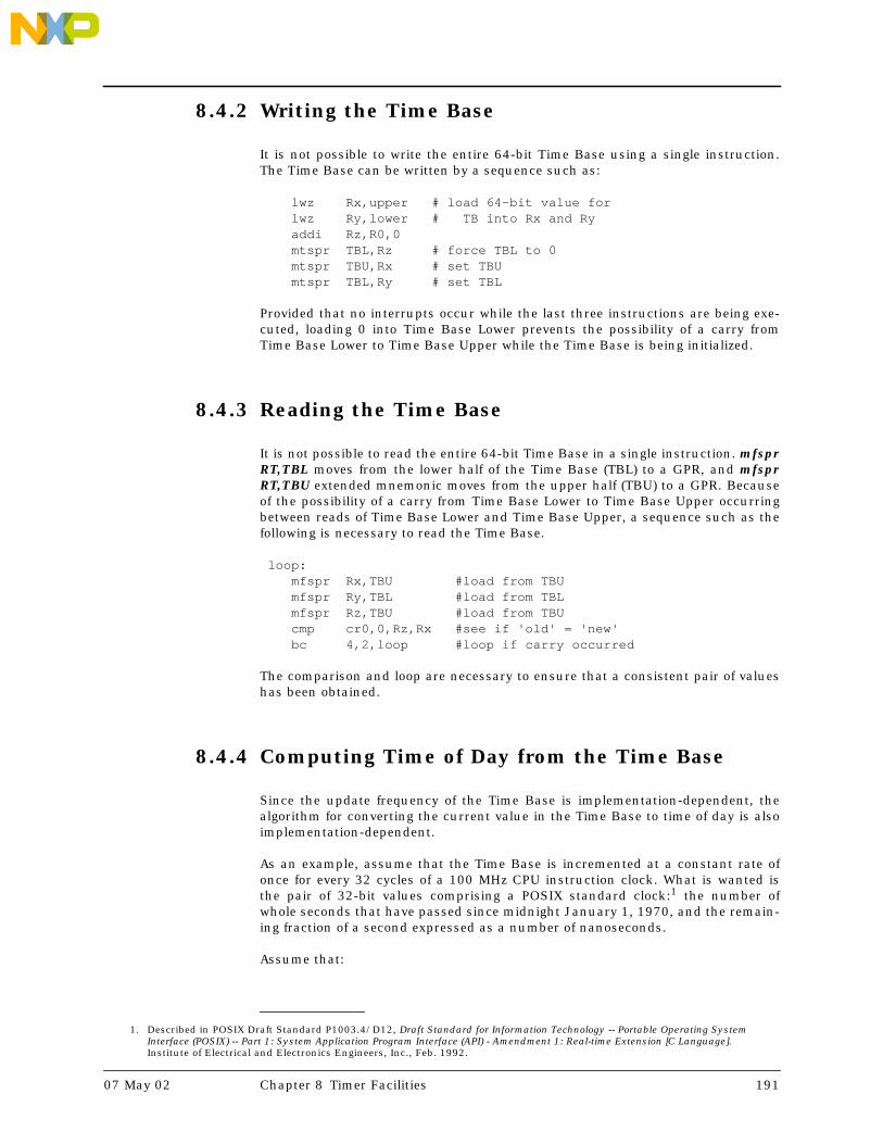
8.4.2 Writing the Time Base
It is not possible to write the entire 64-bit Time Base using a single instruction.The Time Base can be written by a sequence such as:
lwz Rx,upper # load 64-bit value for lwz Ry,lower # TB into Rx and Ry addi Rz,R0,0 mtspr TBL,Rz # force TBL to 0 mtspr TBU,Rx # set TBU mtspr TBL,Ry # set TBL
Provided that no interrupts occur while the last three instructions are being exe-cuted, loading 0 into Time Base Lower prevents the possibility of a carry fromTime Base Lower to Time Base Upper while the Time Base is being initialized.
8.4.3 Reading the Time Base
It is not possible to read the entire 64-bit Time Base in a single instruction. mfsprRT,TBL moves from the lower half of the Time Base (TBL) to a GPR, and mfsprRT,TBU extended mnemonic moves from the upper half (TBU) to a GPR. Becauseof the possibility of a carry from Time Base Lower to Time Base Upper occurringbetween reads of Time Base Lower and Time Base Upper, a sequence such as thefollowing is necessary to read the Time Base.
loop: mfspr Rx,TBU #load from TBU mfspr Ry,TBL #load from TBL mfspr Rz,TBU #load from TBU cmp cr0,0,Rz,Rx #see if 'old' = 'new' bc 4,2,loop #loop if carry occurred
The comparison and loop are necessary to ensure that a consistent pair of valueshas been obtained.
8.4.4 Computing Time of Day from the Time Base
Since the update frequency of the Time Base is implementation-dependent, thealgorithm for converting the current value in the Time Base to time of day is alsoimplementation-dependent.
As an example, assume that the Time Base is incremented at a constant rate ofonce for every 32 cycles of a 100 MHz CPU instruction clock. What is wanted isthe pair of 32-bit values comprising a POSIX standard clock:1 the number ofwhole seconds that have passed since midnight January 1, 1970, and the remain-ing fraction of a second expressed as a number of nanoseconds.
Assume that:
1. Described in POSIX Draft Standard P1003.4/D12, Draft Standard for Information Technology -- Portable Operating SystemInterface (POSIX) -- Part 1: System Application Program Interface (API) - Amendment 1: Real-time Extension [C Language].Institute of Electrical and Electronics Engineers, Inc., Feb. 1992.
07 May 02 Chapter 8 Timer Facilities 191

• The value 0 in the Time Base represents the start time of the POSIX clock (ifthis is not true, a simple 64-bit subtraction will make it so).
• The integer constant ticks_per_sec contains the value
100MHz / 32 = 3,125,000
which is the number of times the Time Base is updated each second.
• The integer constant ns_adj contains the value
1,000,000,000 / 3,125,000 = 320
which is the number of nanoseconds per tick of the Time Base.
The POSIX clock can be computed with an instruction sequence such as this:
# Read Time Baseloop: mfspr Rx,TBU #load from TBU into Rx mfspr Ry,TBL #load from TBL into Ry mfspr Rz,TBU #load from TBU into Rz cmp CR0,0,Rz,Rx #see if 'old TBU' = 'new TBU' bc 4,2,loop #loop if carry occurred rldimi Ry,Rx,32,0 #splice TBU & TBL into Ry## Compute POSIX clock# lwz Rx,ticks_per_sec divd Rz,Ry,Rx #Rz = whole seconds stw Rz,posix_sec mulld Rz,Rz,Rx #Rz = quotient * divisor sub Rz,Ry,Rz #Rz = excess ticks lwz Rx,ns_adj mulld Rz,Rz,Rx #Rz = excess nanoseconds stw Rz,posix_ns
In the absence of a divd instruction (see Appendix A, “Guidelines for 32-bit BookE”, on page 371), direct implementation of the algorithm given above is awkward.1
Such division can be avoided entirely if a time of day clock in POSIX format isupdated at least once each second.
Assume that:
• The operating system maintains the following variables:
– posix_tb (64 bits)– posix_sec (32 bits)– posix_ns (32 bits)
These variables hold the value of the Time Base and the computed POSIX sec-ond and nanosecond values from the last time the POSIX clock wascomputed.
1. See D. E. Knuth, The Art of Computer Programming, Volume 2, Seminumerical Algorithms, Section 4.3.1, Algorithm D. Addi-son-Wesley, 1981.
192 Book E: Enhanced PowerPC Architecture Version 1.0 07 May 02

• The operating system arranges for an interrupt (see Chapter 8 on page 185) tooccur at least once per second, at which time it recomputes the POSIX clockvalues.
• The integer constant billion contains the value 1,000,000,000.
The POSIX clock can be computed with an instruction sequence such as this:
loop: mfspr Rx,TBU #Rx = TBU mfspr Ry,TBL #Ry = TBL mfspr Rz,TBU #Rz = 'new' TBU value cmp CR0,0,Rz,Rx #see if 'old' = 'new' bc 4,2,loop #loop if carry occurred # now have 64-bit TB in Rx and Ry lwz Rz,posix_tb+4 sub Rz,Ry,Rz #Rz = delta in ticks lwz Rw,ns_adj mullw Rz,Rz,Rw #Rz = delta in ns lwz Rw,posix_ns add Rz,Rz,Rw #Rz = new ns value lwz Rw,billion cmp CR0,0,Rz,Rw #see if past 1 second bc 12,0,nochange #branch if not sub Rz,Rz,Rw #adjust nanoseconds lwz Rw,posix_sec addi Rw,Rw,1 #adjust seconds stw Rw,posix_sec #store new seconds nochange: stw Rz,posix_ns #store new ns stw Rx,posix_tb #store new time base stw Ry,posix_tb+4
Note that the upper half of the Time Base does not participate in the calculation todetermine the new POSIX time of day. This is correct as long as the time changedoes not exceed one second.
Non-constant update frequency
In a system in which the update frequency of the Time Base may change overtime, it is not possible to convert an isolated Time Base value into time of day.Instead, a Time Base value has meaning only with respect to the current updatefrequency and the time of day that the update frequency was last changed. Eachtime the update frequency changes, either the system software is notified of thechange via an interrupt (see Chapter 7 on page 143), or the change was instigatedby the system software itself. At each such change, the system software mustcompute the current time of day using the old update frequency, compute a newvalue of ticks_per_sec for the new frequency, and save the time of day, Time Basevalue, and tick rate. Subsequent calls to compute time of day use the currentTime Base value and the saved data.
07 May 02 Chapter 8 Timer Facilities 193

8.5 Decrementer
The Decrementer (DEC) is a 32-bit register. Decrementer bits are numbered 32(most-significant bit) to 63 (least-significant bit).
The contents of the Decrementer can be read into bits 32:63 of a General PurposeRegister using mfspr RT,DEC, setting bits 0:31 of GPR(RT) to zero. The contents ofbits 32:63 of GPR(RS) can be written to the Decrementer using mtspr DEC,RS.
The Decrementer Auto-Reload Register (DECAR) is a 32-bit register. DecrementerAuto-Reload Register bits are numbered 32 (most-significant bit) to 63 (least-sig-nificant bit). The Decrementer Auto-Reload Register is provided to support theauto-reload feature of the Decrementer.
The contents of the Decrementer Auto-Reload Register cannot be read. The con-tents of bits 32:63 of GPR(RS) can be written to the Decrementer Auto-ReloadRegister using mtspr DECAR,RS.
The Decrementer decrements at the same rate that the Time Base increments. ADecrementer event occurs when a decrement occurs on a Decrementer value of0x0000_0001. Upon the occurrence of a Decrementer event, the Decrementer hasthe following basic modes of operation.
Decrement to one and stop on zeroIf TCRARE=0, TSRDIS is set to 1, the value 0x0000_0000 is then placed intothe DEC, and the Decrementer stops decrementing.
If enabled by TCRDIE=1 and MSREE=1, a Decrementer interrupt is taken. SeeSection 7.6.11 on page 167 for details of register behavior caused by the
Decrementer interrupt.
Decrement to one and auto-reloadIf TCRARE=1, TSRDIS is set to 1, the contents of the Decrementer Auto-ReloadRegister is then placed into the DEC, and the Decrementer continuesdecrementing from the reloaded value.
If enabled by TCRDIE=1 and MSREE=1, a Decrementer interrupt is taken. SeeSection 7.6.11 on page 167 for details of register behavior caused by the
Decrementer interrupt.
The Decrementer interrupt handler must reset TSRDIS in order to avoid takinganother, redundant Decrementer interrupt once MSREE is re-enabled (assumingTCRDIE is not cleared instead). This is done by writing a word to Timer StatusRegister using mtspr with a 1 in the bit corresponding to TSRDIS (and any otherbits that are to be cleared) and 0 in all other bits. The write-data to the Timer Sta-tus Register is not direct data, but a mask. A 1 causes the bit to be cleared, and a0 has no effect.
Forcing the Decrementer to 0 using the mtspr instruction will not cause a Decre-menter exception; however, decrementing which was in progress at the instant ofthe mtspr may cause the exception. To eliminate the Decrementer as a source ofexceptions, set TCRDIE to 0 (clear the Decrementer Interrupt Enable bit).
If it is desired to eliminate all Decrementer activity, the procedure is as follows:
1. Write 0 to TCRDIE. This will prevent Decrementer activity from causing
194 Book E: Enhanced PowerPC Architecture Version 1.0 07 May 02

exceptions.
2. Write 0 to TCRARE to disable the Decrementer auto-reload.
3. Write 0 to Decrementer. This will halt Decrementer decrementing. While thisaction will not cause a Decrementer exception to be set in TSRDIS, a nearsimultaneous decrement may have done so.
4. Write 1 to TSRDIS. This action will clear TSRDIS to 0 (see Section 8.3 onpage 188). This will clear any Decrementer exception which may be pending.Because the Decrementer is frozen at zero, no further Decrementer events arepossible.
If the auto-reload feature is disabled (TCRARE=0), then once the Decrementer dec-rements to zero, it will stay there until software reloads it using the mtsprinstruction.
On reset, TCRARE is set to 0. This disables the auto-reload feature.
Book E has changed the definition of the Decrementer from the PowerPC Architec-ture definition. However, Book E permits implementations of the architecture toprovide implementation-dependent facilities to enable emulation of the PowerPCArchitecture definition of the Decrementer for compatibility with legacy systems.There are a number of approaches to providing this compatibility support, andhence Book E allows implementation-dependent discretion. A new mode whichcauses the Decrementer to operate in the PowerPC-compatible mode would berequired by implementations that support such compatibility. A mode bit thatenables this new mode is recommended to be placed in the Timer Control Regis-ter. The PowerPC Decrementer operates continuously, wrapping from 0 to0xFFFF_FFFF and generates an interrupt on every transition of bit 0 of the Decre-menter from 0 to 1, including such a transition caused by a mtspr DEC,RS. ABook E implementation that supports this PowerPC Decrementer mode would berequired to also provide facilities that enable the Book E Decrementer behavior.
8.6 Fixed-Interval Timer
The Fixed-Interval Timer (FIT) is a mechanism for providing timer interrupts witha repeatable period, to facilitate system maintenance. It is similar in function toan auto-reload Decrementer, except that there are fewer selections of interruptperiod available. The Fixed-Interval Timer exception occurs on 0 to 1 transitionsof a selected bit from the Time Base (see Section 8.2 on page 186).
The Fixed-Interval Timer exception is logged by TSRFIS. A Fixed-Interval Timerinterrupt will occur if TCRFIE and MSREE are enabled. See Section 7.6.12 onpage 168 for details of register behavior caused by the Fixed-Interval Timer inter-rupt.
The interrupt handler must reset TSRFIS via software, in order to avoid anotherFixed-Interval Timer interrupt once MSREE is re-enabled (assuming TCRFIE is notcleared instead). This is done by writing a word to the Timer Status Register usingmtspr with a 1 in the bit corresponding to TSRFIS (and any other bits that are tobe cleared) and 0 in all other bits. The write-data to the Timer Status Register isnot direct data, but a mask. A 1 causes the bit to be cleared, and a “0” has noeffect.
07 May 02 Chapter 8 Timer Facilities 195

Note that a Fixed-Interval Timer exception will also occur if the selected Time Basebit transitions from 0 to 1 due to an mtspr TBL,RS that writes a 1 to the bit whenits previous value was 0.
8.7 Watchdog Timer
The Watchdog Timer is a facility intended to aid system recovery from faulty soft-ware or hardware. Watchdog time-outs occur on 0 to 1 transitions of selected bitsfrom the Time Base (see Section 8.2 on page 186).
When a Watchdog Timer time-out occurs while Watchdog Timer Interrupt Statusis clear (TSRWIS = 0) and the next Watchdog Time-out is enabled (TSRENW = 1), aWatchdog Timer exception is generated and logged by setting TSRWIS to 1. This isreferred to as a Watchdog Timer First Time Out. A Watchdog Timer interrupt willoccur if enabled by TCRWIE and MSRCE. See Section 7.6.13 on page 169 fordetails of register behavior caused by the Watchdog Timer interrupt.
The interrupt handler must reset TSRWIS via software, in order to avoid anotherWatchdog Timer interrupt once MSRCE is re-enabled (assuming TCRWIE is notcleared instead). This is done by writing a word to the Timer Status Register usingmtspr with a 1 in the bit corresponding to TSRWIS (and any other bits that are tobe cleared) and a 0 in all other bits. The write-data to the Timer Status Register isnot direct data, but a mask. A 1 causes the bit to be cleared, and a 0 has no effect.
Note that a Watchdog Timer exception will also occur if the selected Time Base bittransitions from 0 to 1 due to an mtspr TBL,RS that writes a 1 to the bit when itsprevious value was 0.
When a Watchdog Timer time-out occurs while TSRWIS = 1 and TSRENW = 1, aprocessor reset occurs if it is enabled by a non-zero value of the Watchdog ResetControl field in the Timer Control Register (TCRWRC). This is referred to as aWatchdog Timer Second Time Out. The assumption is that TSRWIS was notcleared because the processor was unable to execute the Watchdog Timer inter-rupt handler, leaving reset as the only available means to restart the system. Notethat once TCRWRC has been set to a non-zero value, it cannot be reset by software;this feature prevents errant software from disabling the Watchdog Timer resetcapability.
A more complete view of Watchdog Timer behavior is afforded by Figure 8-2 onpage 197 and Table 8-3 on page 197, which describe the Watchdog Timer statemachine and Watchdog Timer controls. The numbers in parentheses in the figurerefer to the discussion of modes of operation which follow the table.
196 Book E: Enhanced PowerPC Architecture Version 1.0 07 May 02

Figure 8-2. Watchdog State Machine
Table 8-3. Watchdog Timer Controls
The controls described in the above table imply three different modes of operationthat a programmer might select for the Watchdog Timer. Each of these modesassumes that TCRWRC has been set to allow processor reset by the Watchdog facil-ity:
1. Always take the Watchdog Timer interrupt when pending, and never attemptto prevent its occurrence. In this mode, the Watchdog Timer interrupt causedby a first time-out is used to clear TSRWIS so a second time-out never occurs.TSRENW is not cleared, thereby allowing the next time-out to cause anotherinterrupt.
2. Always take the Watchdog Timer interrupt when pending, but avoid whenpossible. In this mode a recurring code loop of reliable duration (or perhaps aperiodic interrupt handler such as the Fixed-Interval Timer interrupt han-dler) is used to repeatedly clear TSRENW such that a first time-out exception isavoided, and thus no Watchdog Timer interrupt occurs. Once TSRENW hasbeen cleared, software has between one and two full Watchdog periods beforea Watchdog exception will be posted in TSRWIS. If this occurs before the soft-
Enable NextWDT
(TSRENW)WDT Status
(TSRWIS) Action when timer interval expires
0 0 Set Enable Next Watchdog Timer (TSRENW=1).
0 1 Set Enable Next Watchdog Timer (TSRENW=1).
1 0 Set Watchdog Timer interrupt status bit (TSRWIS=1).If Watchdog Timer interrupt is enabled (TCRWIE=1and MSRCE=1), then interrupt.
1 1 Cause Watchdog Timer reset action specified byTCRWRC. Reset will copy pre-reset TCRWRC intoTSRWRS, then clear TCRWRC.
TSRENW,WIS=0b00
TSRENW,WIS=0b01
TSRENW,WIS=0b10
TSRENW,WIS=0b11
Time-out. No exception recorded in TSRWIS.
Time-out. WDT exception recorded in TSRWIS
Time-out. Set TSRENW
Time-out
(2) SW Loop
(3) SW Loop
(1) Watchdog
Handler
(2)InterruptHandler
TSRWRS ← TCRWRCTCRWRC ← 0b00
WDT interrupt will occur if enabled by
Set TSRENW so next time-out will cause exception.
Interrupt
Watchdog
so next time-out will
If TCRWRC≠00 then RESET, including
cause reset
TCRWIE and MSRCE
07 May 02 Chapter 8 Timer Facilities 197

ware is able to clear TSRENW again, a Watchdog Timer interrupt will occur. Inthis case, the Watchdog Timer interrupt handler will then clear both TSRENWand TSRWIS, in order to (hopefully) avoid the next Watchdog Timer interrupt.
3. Never take the Watchdog Timer interrupt. In this mode, Watchdog Timerinterrupts are disabled (via TCRWIE=0), and the system depends upon a recur-ring code loop of reliable duration (or perhaps a periodic interrupt handlersuch as the Fixed-Interval Timer interrupt handler) to repeatedly clear TSR-
WIS such that a second time-out is avoided, and thus no reset occurs. TSRENWis not cleared, thereby allowing the next time-out to set TSRWIS again. Therecurring code loop must have a period which is less than one WatchdogTimer period in order to guarantee that a Watchdog Timer reset will not occur.
8.8 Freezing the Timer Facilities
The debug mechanism provides a means of temporarily freezing the timers upon adebug event. Specifically, the Time Base and Decrementer can be frozen and pre-vented from incrementing/decrementing, respectively, whenever a debug event isset in the Debug Status Register. This allows a debugger to simulate the appear-ance of ‘real time’, even though the application has been temporarily ‘halted’ toservice the debug event. See the description of bit 63 of the Debug Control Regis-ter 0 (Freeze Timers on Debug Event or DBCR0FT) in Table 9-1 on page 210.
198 Book E: Enhanced PowerPC Architecture Version 1.0 07 May 02

Chapter 9 Debug Facilities
9.1 Background
Book E provides debug facilities to enable hardware and software debug func-tions, such as instructions and data breakpoints and program single stepping.The debug facilities consist of a set of debug control registers (DBCR0, DBCR1,and DBCR2) described in Section 9.4.1, a set of address and data value compareregisters (IAC1, IAC2, IAC3, IAC4, DAC1, DAC2, DVC1, and DVC2) described inSections 9.4.3, 9.4.4, and 9.4.5, a Debug Status Register (DBSR) described isSection 9.4.2 for enabling and recording various kinds of debug events, and a spe-cial Debug interrupt type built into the interrupt mechanism (see Section 7.6.16on page 172). The debug facilities also provide a mechanism for software-con-trolled processor reset, and for controlling the operation of the timers in a debugenvironment.
Access to the debug facilities using the mfspr and mtspr instructions, as well asthe debug interrupt mechanism, are defined as part of Book E. In addition, imple-mentations will typically include debug facilities, modes, and access mechanismswhich are implementation-specific and defined as part of the User’s Manual forthe implementation. For example, implementations will typically provide access tothe debug facilities via a dedicated interface such as the IEEE 1149.1 Test AccessPort (JTAG).
07 May 02 Chapter 9 Debug Facilities 199

Programming NoteThere are two classes of debug exception types:
Type 1: exception before instructionType 2: exception after instruction
Almost all debug exceptions fall into the first category. That is, they all take the inter-rupt upon encountering an instruction having the exception without updating anyarchitectural state (other than DBSR, CSRR0, CSRR1, MSR) for that instruction.
The CSRR0 for this type of exception points to the instruction that encountered theexception. This includes IAC, DAC, branch taken, etc.
The only exception which fall into the second category is the instruction complete debugexception. This exception is taken upon completing and updating one instruction andthen pointing CSRR0 to the next instruction to execute.
To make forward progress for any Type 1 debug exception one does the following:
1. Software sets up Type 1 exceptions (e.g. branch taken debug exceptions) and thenreturns to normal program operation
2. Hardware takes critical debug interrupt upon the first branch taken debugexception, pointing to the branch with CSRR0.
3. Software, in the debug handler, sees the branch taken exception type, does whateverlogging/analysis it wants to, then clears all debug event enables in the DBCR exceptfor the instruction complete debug event enable.
4. Software does an rfci.
5. Hardware would execute and complete one instruction (the branch taken in thiscase), and then take a critical debug interrupt with CSRR0 pointing to the target ofthe branch.
6. Software would see the instruction complete interrupt type. It clears the instructioncomplete event enable, then enables the branch taken interrupt event again.
7. Software does an rfci.
8. Hardware resumes on the target of the taken branch and continues until anothertaken branch, in which case we end up at step 2 again.
This, at first, seems like a double tax (i.e. 2 debug interrupts for every instance of a Type1 exception), but it doesn't seem like any other clean way to make forward progress onType 1 debug exceptions. The only other way to avoid the double tax is to have thedebug handler routine actually emulate the instruction pointed to for the Type 1 excep-tions, determine the next instruction that would have been executed by the interruptedprogram flow and load the CSRR0 with that address and do an rfci; this is probably notfaster.
200 Book E: Enhanced PowerPC Architecture Version 1.0 07 May 02

9.2 Internal Debug Mode
Debug events include such things as instruction and data breakpoints. Thesedebug events cause status bits to be set in the Debug Status Register. The exist-ence of a set bit in the Debug Status Register is considered a Debug exception.Debug exceptions, if enabled, will cause Debug interrupts.
There are two different mechanisms that control whether Debug interrupts areenabled. The first is the MSRDE bit, and this bit must be set to 1 to enable Debuginterrupts. The second mechanism is an enable bit in the Debug Control Register0 (DBCR0). This bit is the Internal Debug Mode bit (DBCR0IDM), and it must alsobe set to 1 to enable Debug interrupts.
When DBCR0IDM=1, the processor is in Internal Debug Mode. In this mode, debugevents will (if also enabled by MSRDE) cause Debug interrupts. Software at theDebug interrupt vector location will thus be given control upon the occurrence ofa debug event, and can access (via the normal instructions) all architected proces-sor resources. In this fashion, debug monitor software can control the processorand gather status, and interact with debugging hardware connected to the proces-sor.
When the processor is not in Internal Debug Mode (DBCR0IDM=0), debug eventsmay still occur and be recorded in the Debug Status Register. These exceptionsmay be monitored via software by reading the Debug Status Register (usingmfspr), or may eventually cause a Debug interrupt if later enabled by settingDBCR0IDM=1 (and MSRDE=1). Processor behavior when debug events occur whileDBCR0IDM=0 is implementation-dependent. The remainder of this chapter dis-cusses processor behavior with the presumption that DBCR0IDM=1.
9.3 Debug Events
Debug events are used to cause Debug exceptions to be recorded in the DebugStatus Register (see Table 9-4 on page 217). In order for a debug event to beenabled to set a Debug Status Register bit and thereby cause a Debug exception,the specific event type must be enabled by a corresponding bit or bits in theDebug Control Registers (DBCR0 defined in Table 9-1, DBCR1 defined in Table 9-2, or DBCR2 defined in Table 9-3) (in most cases; the Unconditional Debug Event(UDE) is an exception to this rule). Once a Debug Status Register bit is set, ifDebug interrupts are enabled by MSRDE, a Debug interrupt will be generated.
Certain debug events are not allowed to occur when MSRDE=0. In such situations,no Debug exception occurs and thus no Debug Status Register bit is set. Otherdebug events may cause Debug exceptions and set Debug Status Register bitsregardless of the state of MSRDE. The associated Debug interrupts that resultfrom such Debug exceptions will be delayed until MSRDE=1, provided the excep-tions have not been cleared from the Debug Status Register in the meantime.
Any time that a Debug Status Register bit is allowed to be set while MSRDE=0, aspecial Debug Status Register bit, Imprecise Debug Event (DBSRIDE), will also beset. DBSRIDE indicates that the associated Debug exception bit in the Debug Sta-tus Register was set while Debug interrupts were disabled via the MMSRDE bit.Debug interrupt handler software can use this bit to determine whether theaddress recorded in the Critical Save/Restore Register 0 should be interpreted asthe address associated with the instruction causing the Debug exception, or sim-
07 May 02 Chapter 9 Debug Facilities 201

ply the address of the instruction after the one which set the MSRDE bit, therebyenabling the delayed Debug interrupt.
Debug interrupts are ordered with respect to other interrupt types (see Section7.8 on page 174). Debug exceptions are prioritized with respect to other excep-tions (see Section 7.9 on page 178).
There are eight types of debug events defined:
1. Instruction Address Compare debug events2. Data Address Compare debug events3. Trap debug events4. Branch Taken debug events5. Instruction Complete debug events6. Interrupt Taken debug events7. Return debug events8. Unconditional debug events
9.3.1 Instruction Address Compare Debug Event
One or more Instruction Address Compare debug events (IAC1, IAC2, IAC3 orIAC4) occur if they are enabled and execution is attempted of an instruction at anaddress that meets the criteria specified in the DBCR0, DBCR1, IAC1, IAC2, IAC3,and IAC4 Registers.
Instruction Address Compare User/Supervisor ModeDBCR1IAC1US specifies whether IAC1 debug events can occur in user mode orsupervisor mode, or both.
DBCR1IAC2US specifies whether IAC2 debug events can occur in user mode orsupervisor mode, or both.
DBCR1IAC3US specifies whether IAC3 debug events can occur in user mode orsupervisor mode, or both.
DBCR1IAC4US specifies whether IAC4 debug events can occur in user mode orsupervisor mode, or both.
Effective/Real Address ModeDBCR1IAC1ER specifies whether effective addresses, real addresses, effectiveaddresses and MSRIS=0, or effective addresses and MSRIS=1 are used indetermining an address match on IAC1 debug events.
DBCR1IAC2ER specifies whether effective addresses, real addresses, effectiveaddresses and MSRIS=0, or effective addresses and MSRIS=1 are used indetermining an address match on IAC2 debug events.
DBCR1IAC3ER specifies whether effective addresses, real addresses, effectiveaddresses and MSRIS=0, or effective addresses and MSRIS=1 are used indetermining an address match on IAC3 debug events.
DBCR1IAC4ER specifies whether effective addresses, real addresses, effectiveaddresses and MSRIS=0, or effective addresses and MSRIS=1 are used indetermining an address match on IAC4 debug events.
202 Book E: Enhanced PowerPC Architecture Version 1.0 07 May 02

Instruction Address Compare ModeDBCR1IAC12M specifies whether all or some of the bits of the address of theinstruction fetch must match the contents of the Instruction AddressCompare 1 Register or Instruction Address Compare 2 Register, whether theaddress must be inside a specific range specified by the Instruction AddressCompare 1 Register and Instruction Address Compare 2 Register or outside aspecific range specified by the Instruction Address Compare 1 Register andInstruction Address Compare 2 Register for an IAC1 or IAC2 debug event tooccur.
DBCR1IAC34M specifies whether all or some of the bits of the address of theinstruction fetch must match the contents of the IAC3 Register or IAC4Register, whether the address must be inside a specific range specified by theIAC3 Register and IAC4 Register or outside a specific range specified by theIAC3 Register and IAC4 Register for an IAC3 or IAC4 debug event to occur.
There are four instruction address compare modes.
– Exact address compare modeIf the 64-bit address of the instruction fetch is equal to the value in theenabled IAC register, an instruction address match occurs.
– Address bit match modeFor IAC1 and IAC2 debug events, if the address of the instruction fetchaccess, ANDed with the contents of the Instruction Address Compare 2Register, are equal to the contents of the Instruction Address Compare 1Register, also ANDed with the contents of the Instruction AddressCompare 2 Register, an instruction address match occurs.
For IAC3 and IAC4 debug events, if the address of the instruction fetch,ANDed with the contents of the Instruction Address Compare 4 Register,are equal to the contents of the Instruction Address Compare 3 Register,also ANDed with the contents of the Instruction Address Compare 4Register, an instruction address match occurs.
– Inclusive address range compare modeFor IAC1 and IAC2 debug events, if the 64-bit address of the instructionfetch is greater than or equal to the contents of the Instruction AddressCompare 1 Register and less than the contents of the Instruction AddressCompare 2 Register, an instruction address match occurs.
For IAC3 and IAC4 debug events, if the 64-bit address of the instructionfetch is greater than or equal to the contents of the Instruction AddressCompare 3 Register and less than the contents of the Instruction AddressCompare 4 Register, an instruction address match occurs.
– Exclusive address range compare modeFor IAC1 and IAC2 debug events, if the 64-bit address of the instructionfetch is less than the contents of the Instruction Address Compare 1Register or greater than or equal to the contents of the Instruction AddressCompare 2 Register, an instruction address match occurs.
For IAC3 and IAC4 debug events, if the 64-bit address of the instructionfetch is less than the contents of the Instruction Address Compare 3Register or greater than or equal to the contents of the Instruction AddressCompare 4 Register, an instruction address match occurs.
See Table 9-1 on page 210 and Table 9-2 on page 212 for a detailed description ofDBCR0 and DBCR1 and the modes of for detecting IAC1, IAC2, IAC3 and IAC4
07 May 02 Chapter 9 Debug Facilities 203

debug events. Instruction Address Compare debug events can occur regardless ofthe setting of MSRDE or DBCR0IDM.
When an Instruction Address Compare debug event occurs, the correspondingDBSRIAC1, DBSRIAC2, DBSRIAC3, or DBSRIAC4 bit or bits are set to record thedebug exception. If MSRDE=0, DBSRIDE is also set to 1 to record the imprecisedebug event.
If MSRDE=1 (i.e. Debug interrupts are enabled) at the time of the InstructionAddress Compare debug exception, a Debug interrupt will occur immediately (pro-vided there exists no higher priority exception which is enabled to cause an inter-rupt). The execution of the instruction causing the exception will be suppressed,and Critical Save/Restore Register 0 will be set to the address of the exceptinginstruction.
If MSRDE=0 (i.e. Debug interrupts are disabled) at the time of the InstructionAddress Compare debug exception, a Debug interrupt will not occur, and theinstruction will complete execution (provided the instruction is not causing someother exception which will generate an enabled interrupt).
Later, if the debug exception has not been reset by clearing DBSRIAC1, DBSRIAC2,DBSRIAC3, and DBSRIAC4, and MSRDE is set to 1, a delayed Debug interrupt willoccur. In this case, Critical Save/Restore Register 0 will contain the address of theinstruction after the one which enabled the Debug interrupt by setting MSRDE to1. Software in the Debug interrupt handler can observe DBSRIDE to determinehow to interpret the value in Critical Save/Restore Register 0.
9.3.2 Data Address Compare Debug Event
One or more Data Address Compare debug events (DAC1R, DAC1W, DAC2R,DAC2W) occur if they are enabled, execution is attempted of a data storage accessinstruction, and the type, address, and possibly even the data value of the datastorage access meet the criteria specified in the Debug Control Register 0, DebugControl Register 2, and the DAC1, DAC2, DVC1, and DVC2 registers.
Data Address Compare Read/Write EnableDBCR0DAC1 specifies whether DAC1R debug events can occur on read-typedata storage accesses and whether DAC1W debug events can occur on write-type data storage accesses.
DBCR0DAC2 specifies whether DAC2R debug events can occur on read-typedata storage accesses and whether DAC2W debug events can occur on write-type data storage accesses.
All Load instructions are considered reads with respect to debug events, whileall Store instructions are considered writes with respect to debug events. Inaddition, the Cache Management instructions, and certain special cases, arehandled as follows.
– dcbt[e], dcbtst[e], icbt[e], and icbi[e] are all considered reads with respectto debug events. Note that dcbt[e], dcbtst[e], and icbt[e] are treated as no-operations when they report Data Storage or Data TLB Miss exceptions,instead of being allowed to cause interrupts. However, these instructionsare allowed to cause Debug interrupts, even when they would otherwisehave been no-op’ed due to a Data Storage or Data TLB Miss exception.
– dcbz[e], dcbi[e], dcbf[e], dcba[e], and dcbst[e] are all considered writes
204 Book E: Enhanced PowerPC Architecture Version 1.0 07 May 02

with respect to debug events. Note that dcbf[e] and dcbst[e] are consideredreads with respect to Data Storage exceptions, since they do not actuallychange the data at a given address. However, since the execution of theseinstructions may result in write activity on the processor’s data bus, theyare treated as writes with respect to debug events.
Indexed-string instructions (lswx, stswx) for which the XER field specifieszero bytes as the length of the string are treated as no-ops, and are notallowed to cause Data Address Compare debug events.
Data Address Compare User/Supervisor ModeDBCR2DAC1US specifies whether DAC1R and DAC1W debug events can occurin user mode or supervisor mode, or both.
DBCR2DAC2US specifies whether DAC2R and DAC2W debug events can occurin user mode or supervisor mode, or both.
Effective/Real Address ModeDBCR2DAC1ER specifies whether effective addresses, real addresses, effectiveaddresses and MSRDS=0, or effective addresses and MSRDS=1 are used to indetermining an address match on DAC1R and DAC1W debug events.
DBCR2DAC2ER specifies whether effective addresses, real addresses, effectiveaddresses and MSRDS=0, or effective addresses and MSRDS=1 are used to indetermining an address match on DAC2R and DAC2W debug events.
Data Address Compare ModeDBCR2DAC12M specifies whether all or some of the bits of the address of thedata storage access must match the contents of the Data Address Compare 1Register or Data Address Compare 2 Register, whether the address must beinside a specific range specified by the Data Address Compare 1 Register andData Address Compare 2 Register or outside a specific range specified by theData Address Compare 1 Register and Data Address Compare 2 Register for aDAC1R, DAC1W, DAC2R or DAC2W debug event to occur.
There are four data address compare modes.
– Exact address compare modeIf the 64-bit address of the data storage access is equal to the value in theenabled Data Address Compare register, a data address match occurs.
– Address bit match modeIf the address of the data storage access, ANDed with the contents of theData Address Compare 2 Register, are equal to the contents of the DataAddress Compare 1 Register, also ANDed with the contents of the DataAddress Compare 2 Register, a data address match occurs.
– Inclusive address range compare modeIf the 64-bit address of the data storage access is greater than or equal tothe contents of the Data Address Compare 1 Register and less than thecontents of the Data Address Compare 2 Register, a data address matchoccurs.
Engineering Notedcba[e], dcbt[e], dcbtst[e], and icbt[e] may cause a Data Address Compare debugevent even when they are otherwise being no-op’ed due to causing a Data Storage orData TLB Miss exception. However, signalling a Debug exception is not required inthese cases.
07 May 02 Chapter 9 Debug Facilities 205

– Exclusive address range compare modeIf the 64-bit address of the data storage access is less than the contents ofthe Data Address Compare 1 Register or greater than or equal to thecontents of the Data Address Compare 2 Register, a data address matchoccurs.
Data Value Compare ModeDBCR2DVC1M and DBCR2DVC1BE specify whether and how the data valuebeing accessed by the storage access must match the contents of the DataValue Compare 1 Register for a DAC1R or DAC1W debug event to occur.
DBCR2DVC2M and DBCR2DVC2BE specify whether and how the data valuebeing accessed by the storage access must match the contents of the DataValue Compare 2 Register for a DAC2R or DAC2W debug event to occur.
See Table 9-1 on page 210 and Table 9-3 on page 215 for a detailed description ofDBCR0 and DBCR2 and the modes for detecting Data Address Compare debugevents. Data Address Compare debug events can occur regardless of the setting ofMSRDE or DBCR0IDM.
When an Data Address Compare debug event occurs, the correspondingDBSRDAC1R, DBSRDAC1W, DBSRDAC2R, or DBSRDAC2W bit or bits are set to 1 torecord the debug exception. If MSRDE=0, DBSRIDE is also set to 1 to record theimprecise debug event.
If MSRDE=1 (i.e. Debug interrupts are enabled) at the time of the Data AddressCompare debug exception, a Debug interrupt will occur immediately (providedthere exists no higher priority exception which is enabled to cause an interrupt),the execution of the instruction causing the exception will be suppressed, andCritical Save/Restore Register 0 will be set to the address of the excepting instruc-tion. Depending on the type of instruction and/or the alignment of the dataaccess, the instruction causing the exception may have been partially executed(see Section 7.7 on page 173).
If MSRDE=0 (i.e. Debug interrupts are disabled) at the time of the Data AddressCompare debug exception, a Debug interrupt will not occur, and the instructionwill complete execution (provided the instruction is not causing some other excep-tion which will generate an enabled interrupt). Also, DBSRIDE is set to indicatethat the debug exception occurred while Debug interrupts were disabled byMSRDE=0.
Later, if the debug exception has not been reset by clearing DBSRDAC1R,DBSRDAC1W, DBSRDAC2R, DBSRDAC2W, and MSRDE is set to 1, a delayed Debuginterrupt will occur. In this case, Critical Save/Restore Register 0 will contain theaddress of the instruction after the one which enabled the Debug interrupt by set-ting MSRDE to 1. Software in the Debug interrupt handler can observe DBSRIDE todetermine how to interpret the value in Critical Save/Restore Register 0.
9.3.3 Trap Debug Event
A Trap debug event (TRAP) occurs if DBCR0TRAP=1 (i.e. Trap debug events areenabled) and a Trap instruction (tw, twi, td, tdi) is executed and the conditionsspecified by the instruction for the trap are met. The event can occur regardless ofthe setting of MSRDE or DBCR0IDM.
When a Trap debug event occurs, DBSRTR is set to 1 to record the debug excep-tion. If MSRDE=0, DBSRIDE is also set to 1 to record the imprecise debug event.
206 Book E: Enhanced PowerPC Architecture Version 1.0 07 May 02

If MSRDE=1 (i.e. Debug interrupts are enabled) at the time of the Trap debugexception, a Debug interrupt will occur immediately (provided there exists nohigher priority exception which is enabled to cause an interrupt), and CSRR0 willbe set to the address of the excepting instruction.
If MSRDE=0 (i.e. Debug interrupts are disabled) at the time of the Trap debugexception, a Debug interrupt will not occur, and a Trap exception type Programinterrupt will occur instead if the trap condition is met.
Later, if the debug exception has not been reset by clearing DBSRTR, and MSRDEis set to 1, a delayed Debug interrupt will occur. In this case, Critical Save/Restore Register 0 will contain the address of the instruction after the one whichenabled the Debug interrupt by setting MSRDE to 1. Software in the debug inter-rupt handler can observe DBSRIDE to determine how to interpret the value in Crit-ical Save/Restore Register 0.
9.3.4 Branch Taken Debug Event
A Branch Taken debug event (BRT) occurs if DBCR0BRT=1 (i.e. Branch TakenDebug events are enabled), execution is attempted of a branch instruction whosedirection will be taken (that is, either an unconditional branch, or a conditionalbranch whose branch condition is met), and MSRDE=1.
Branch Taken debug events are not recognized if MSRDE=0 at the time of the exe-cution of the branch instruction and thus DBSRIDE can not be set by a BranchTaken debug event. This is because branch instructions occur very frequently.Allowing these common events to be recorded as exceptions in the DBSR whiledebug interrupts are disabled via MSRDE would result in an inordinate number ofimprecise Debug interrupts.
When a Branch Taken debug event occurs, the DBSRBRT bit is set to 1 to recordthe debug exception and a Debug interrupt will occur immediately (provided thereexists no higher priority exception which is enabled to cause an interrupt). Theexecution of the instruction causing the exception will be suppressed, and CriticalSave/Restore Register 0 will be set to the address of the excepting instruction.
9.3.5 Instruction Complete Debug Event
An Instruction Complete debug event (ICMP) occurs if DBCR0ICMP=1 (i.e. Instruc-tion Complete debug events are enabled), execution of any instruction is com-pleted, and MSRDE=1. Note that if execution of an instruction is suppressed dueto the instruction causing some other exception which is enabled to generate aninterrupt, then the attempted execution of that instruction does not cause anInstruction Complete debug event. The sc instruction does not fall into the cate-gory of an instruction whose execution is suppressed, since the instruction actu-ally completes execution and then generates a System Call interrupt. In this case,the Instruction Complete debug exception will also be set.
Instruction Complete debug events are not recognized if MSRDE=0 at the time ofthe execution of the instruction, DBSRIDE can not be set by an ICMP debug event.This is because allowing the common event of Instruction Completion to berecorded as an exception in the DBSR while Debug interrupts are disabled viaMSRDE would mean that the Debug interrupt handler software would receive an
07 May 02 Chapter 9 Debug Facilities 207

inordinate number of imprecise Debug interrupts every time Debug interruptswere re-enabled via MSRDE.
When an Instruction Complete debug event occurs, DBSRICMP is set to 1 to recordthe debug exception, a Debug interrupt will occur immediately (provided thereexists no higher priority exception which is enabled to cause an interrupt), andCritical Save/Restore Register 0 will be set to the address of the instruction afterthe one causing the Instruction Complete debug exception.
9.3.6 Interrupt Taken Debug Event
An Interrupt Taken debug event (IRPT) occurs if DBCR0IRPT=1 (i.e. InterruptTaken debug events are enabled) and a non-critical interrupt occurs. InterruptTaken debug events can occur regardless of the setting of MSRDE.
Only non-critical class interrupts can cause an Interrupt Taken debug eventbecause all critical interrupts automatically clear MSRDE, and thus would alwaysprevent the associated Debug interrupt from occurring precisely. Also, Debuginterrupts themselves are critical class interrupts, and thus any Debug interrupt(for any other debug event) would always end up setting the additional exceptionof DBSRIRPT upon entry to the Debug interrupt handler. At this point, the Debuginterrupt handler would be unable to determine whether or not the InterruptTaken debug event was related to the original debug event.
When an Interrupt Taken debug event occurs, DBSRIRPT is set to 1 to record thedebug exception. If MSRDE=0, DBSRIDE is also set to 1 to record the imprecisedebug event.
If MSRDE=1 (i.e. Debug interrupts are enabled) at the time of the Interrupt Takendebug event, a Debug interrupt will occur immediately (provided there exists nohigher priority exception which is enabled to cause an interrupt), and CriticalSave/Restore Register 0 will be set to the address of the non-critical interrupt vec-tor which caused the Interrupt Taken debug event. No instructions at the non-critical interrupt handler will have been executed.
If MSRDE=0 (i.e. Debug interrupts are disabled) at the time of the Interrupt Takendebug event, a Debug interrupt will not occur, and the handler for the interruptwhich caused the Interrupt Taken debug event will be allowed to execute.
Later, if the debug exception has not been reset by clearing DBSRIRPT, and MSRDEis set to 1, a delayed Debug interrupt will occur. In this case, CSRR0 will containthe address of the instruction after the one which enabled the Debug interrupt bysetting MSRDE to 1. Software in the Debug interrupt handler can observe theDBSRIDE bit to determine how to interpret the value in Critical Save/Restore Reg-ister 0.
9.3.7 Return Debug Event
A Return debug event (RET) occurs if DBCR0RET=1 and an attempt is made toexecute an rfi. Return debug events can occur regardless of the setting of MSRDE.
When a Return debug event occurs, DBSRRET is set to 1 to record the debugexception. If MSRDE=0, DBSRIDE is also set to 1 to record the imprecise debugevent.
208 Book E: Enhanced PowerPC Architecture Version 1.0 07 May 02

If MSRDE=1 at the time of the Return Debug event, a Debug interrupt will occurimmediately, and Critical Save/Restore Register 0 will be set to the address of therfi.
If MSRDE=0 at the time of the Return Debug event, a Debug interrupt will notoccur.
Later, if the Debug exception has not been reset by clearing DBSRRET, and MSRDEis set to 1, a delayed imprecise Debug interrupt will occur. In this case, CriticalSave/Restore Register 0 will contain the address of the instruction after the onewhich enabled the Debug interrupt by setting MSRDE to 1. An imprecise Debuginterrupt can be caused by executing an rfi when DBCR0RET=1 and MSRDE=0,and the execution of that rfi happens to cause MSRDE to be set to 1. Software inthe Debug interrupt handler can observe the DBSRIDE bit to determine how tointerpret the value in Critical Save/Restore Register 0.
9.3.8 Unconditional Debug Event
An Unconditional debug event (UDE) occurs when the Unconditional Debug Event(UDE) signal is activated by the debug mechanism. The exact definition of theUDE signal and how it is activated is implementation-dependent (see the User’sManual for the implementation for more details). The Unconditional debug eventis the only debug event which does not have a corresponding enable bit for theevent in DBCR0 (hence the name of the event). The Unconditional debug eventcan occur regardless of the setting of MSRDE.
When an Unconditional debug event occurs, the DBSRUDE bit is set to 1 to recordthe Debug exception. If MSRDE=0, DBSRIDE is also set to 1 to record the imprecisedebug event.
If MSRDE=1 (i.e. Debug interrupts are enabled) at the time of the UnconditionalDebug exception, a Debug interrupt will occur immediately (provided there existsno higher priority exception which is enabled to cause an interrupt), and CriticalSave/Restore Register 0 will be set to the address of the instruction which wouldhave executed next had the interrupt not occurred.
If MSRDE=0 (i.e. Debug interrupts are disabled) at the time of the UnconditionalDebug exception, a Debug interrupt will not occur.
Later, if the Unconditional Debug exception has not been reset by clearingDBSRUDE, and MSRDE is set to 1, a delayed Debug interrupt will occur. In thiscase, CSRR0 will contain the address of the instruction after the one whichenabled the Debug interrupt by setting MSRDE to 1. Software in the Debug inter-rupt handler can observe DBSRIDE to determine how to interpret the value in Crit-ical Save/Restore Register 0.
07 May 02 Chapter 9 Debug Facilities 209

9.4 Debug Registers
This section describes debug-related registers that are accessible to software run-ning on the processor. These registers are intended for use by special debug toolsand debug software, and not by general application or operating system code.
9.4.1 Debug Control Registers
Debug Control Register 0 (DBCR0), Debug Control Register 1 (DBCR1), andDebug Control Register 2 (DBCR2) are each 32-bit registers. Bits of Debug ControlRegister 0, Debug Control Register 1, and Debug Control Register 2 are numbered32 (most-significant bit) to 63 (least-significant bit). Debug Control Register 0,Debug Control Register 1, and Debug Control Register 2 are used to enable debugevents, reset the processor, control timer operation during debug events, and setthe debug mode of the processor.
9.4.1.1 Debug Control Register 0
The contents of the Debug Control Register 0 can be read into bits 32:63 a Gen-eral Purpose Register using mfspr RT,DBCR0, setting bits 0:31 of GPR(RT) to 0.The contents of bits 32:63 of a General Purpose Register can be written to theDebug Control Register 0 using mtspr DBCR0,RS. Table 9-1 provides bit defini-tions for Debug Control Register 0.
Table 9-1. Debug Control Register 0 Definition
Bit(s) Description
32 Allocated for implementation-dependent use. See the User’s Manual for the imple-mentation for details.
33 Internal Debug Mode (IDM)
=0 Debug interrupts are disabled.
=1 If MSRDE=1, then the occurrence of a debug event or the recording of anearlier debug event in the Debug Status Register when MSRDE=0 orDBCR0IDM=0 will cause a Debug interrupt.
Programming NoteSoftware must clear debug event status in the Debug Status Register in the Debuginterrupt handler when a Debug interrupt is taken before re-enabling interruptsvia MSRDE. Otherwise, redundant Debug interrupts will be taken for the same de-bug event.
34:35 Reset (RST)
=00 No action
=01 See the User’s Manual for the implementation for details.
=10 See the User’s Manual for the implementation for details.
=11 See the User’s Manual for the implementation for details.
WarningWriting 0b01, 0b10, or 0b11 to these bits may cause a processor reset to occur.
36 Instruction Completion Debug Event (ICMP)
=0 ICMP debug events are disabled
=1 ICMP debug events are enabled
NoteInstruction Completion will not cause an ICMP debug event if MSRDE=0.
210 Book E: Enhanced PowerPC Architecture Version 1.0 07 May 02

37 Branch Taken Debug Event Enable (BRT)
=0 BRT debug events are disabled
=1 BRT debug events are enabled
NoteTaken branches will not cause a BRT debug event if MSRDE=0.
38 Interrupt Taken Debug Event Enable (IRPT)
=0 IRPT debug events are disabled
=1 IRPT debug events are enabled
NoteCritical interrupts will not cause an IRPT debug event if MSRDE=0.
39 Trap Debug Event Enable (TRAP)
=0 TRAP debug events cannot occur
=1 TRAP debug events can occur
40 Instruction Address Compare 1 Debug Event Enable (IAC1)
=0 IAC1 debug events cannot occur
=1 IAC1 debug events can occur
41 Instruction Address Compare 2 Debug Event Enable (IAC2)
=0 IAC2 debug events cannot occur
=1 IAC2 debug events can occur
42 Instruction Address Compare 3 Debug Event Enable (IAC3)
=0 IAC3 debug events cannot occur
=1 IAC3 debug events can occur
43 Instruction Address Compare 4 Debug Event Enable (IAC4)
=0 IAC4 debug events cannot occur
=1 IAC4 debug events can occur
44:45 Data Address Compare 1 Debug Event Enable (DAC1)
=00 DAC1 debug events cannot occur
=01 DAC1 debug events can occur only if a store-type data storage access
=10 DAC1 debug events can occur only if a load-type data storage access
=11 DAC1 debug events can occur on any data storage access
46:47 Data Address Compare 2 Debug Event Enable (DAC2)
=00 DAC2 debug events cannot occur
=01 DAC2 debug events can occur only if a store-type data storage access
=10 DAC2 debug events can occur only if a load-type data storage access
=11 DAC2 debug events can occur on any data storage access
48 Return Debug Event Enable (RET)
=0 RET debug events cannot occur
=1 RET debug events can occur
NoteReturn From Critical Interrupt will not cause an RET debug event if MSRDE=0.
49:62 Reserved
63 Freeze Timers on Debug Event (FT)
=0 Enable clocking of timers
=1 Disable clocking of timers if any DBSR bit is set (except MRR)
Bit(s) Description
07 May 02 Chapter 9 Debug Facilities 211

9.4.1.2 Debug Control Register 1
The contents of the Debug Control Register 1 can be read into bits 32:63 a Gen-eral Purpose Register using mfspr RT,DBCR1, setting bits 0:31 of GPR(RT) to 0.The contents of bits 32:63 of a General Purpose Register can be written to theDebug Control Register 1 using mtspr DBCR1,RS. Table 9-2 provides bit defini-tions for the Debug Control Register 1.
Table 9-2. Debug Control Register 1 Definition
Bit(s) Description
32:33 Instruction Address Compare 1 User/Supervisor Mode (IAC1US)
=00 IAC1 debug events can occur
=01 Reserved
=10 IAC1 debug events can occur only if MSRPR=0
=11 IAC1 debug events can occur only if MSRPR=1
34:35 Instruction Address Compare 1 Effective/Real Mode (IAC1ER)
=00 IAC1 debug events are based on effective addresses
=01 IAC1 debug events are based on real addresses
=10 IAC1 debug events are based on effective addresses and can occur only ifMSRIS=0
=11 IAC1 debug events are based on effective addresses and can occur only ifMSRIS=1
36:37 Instruction Address Compare 2 User/Supervisor Mode (IAC2US)
=00 IAC2 debug events can occur
=01 Reserved
=10 IAC2 debug events can occur only if MSRPR=0
=11 IAC2 debug events can occur only if MSRPR=1
38:39 Instruction Address Compare 2 Effective/Real Mode (IAC2ER)
=00 IAC2 debug events are based on effective addresses
=01 IAC2 debug events are based on real addresses
=10 IAC2 debug events are based on effective addresses and can occur only ifMSRIS=0
=11 IAC2 debug events are based on effective addresses and can occur only ifMSRIS=1
40:41 Instruction Address Compare 1/2 Mode (IAC12M)
=00 Exact address compare
• IAC1 debug events can occur only if the address of the instruction fetchis equal to the value specified in IAC1.
• IAC2 debug events can occur only if the address of the instruction fetchis equal to the value specified in IAC2.
=01 Address bit match
• IAC1 and IAC2 debug events can occur only if the address of the instruc-tion fetch, ANDed with the contents of IAC2 are equal to the contents ofIAC1, also ANDed with the contents of IAC2.
• If IAC1US≠IAC2US or IAC1ER≠IAC2ER, results are boundedly unde-fined.
=10 Inclusive address range compare
• IAC1 and IAC2 debug events can occur only if the address of the instruc-tion fetch is greater than or equal to the value specified in IAC1 and lessthan the value specified in IAC2.
• If IAC1US≠IAC2US or IAC1ER≠IAC2ER, results are boundedly unde-fined.
212 Book E: Enhanced PowerPC Architecture Version 1.0 07 May 02

40:41 =11 Exclusive address range compare
• IAC1 and IAC2 debug events can occur only if the address of the instruc-tion fetch is less than the value specified in IAC1 or is greater than orequal to the value specified in IAC2.
• If IAC1US≠IAC2US or IAC1ER≠IAC2ER, results are boundedly unde-fined.
42:47 Reserved
48:49 Instruction Address Compare 3 User/Supervisor Mode (IAC3US)
=00 IAC3 debug events can occur
=01 Reserved
=10 IAC3 debug events can occur only if MSRPR=0
=11 IAC3 debug events can occur only if MSRPR=1
50:51 Instruction Address Compare 3 Effective/Real Mode (IAC3ER)
=00 IAC3 debug events are based on effective addresses
=01 IAC3 debug events are based on real addresses
=10 IAC3 debug events are based on effective addresses and can occur only ifMSRIS=0
=11 IAC3 debug events are based on effective addresses and can occur only ifMSRIS=1
52:53 Instruction Address Compare 4 User/Supervisor Mode (IAC4US)
=00 IAC4 debug events can occur
=01 Reserved
=10 IAC4 debug events can occur only if MSRPR=0
=11 IAC4 debug events can occur only if MSRPR=1
54:55 Instruction Address Compare 4 Effective/Real Mode (IAC4ER)
=00 IAC4 debug events are based on effective addresses
=01 IAC4 debug events are based on real addresses
=10 IAC4 debug events are based on effective addresses and can occur only ifMSRIS=0
=11 IAC4 debug events are based on effective addresses and can occur only ifMSRIS=1
Bit(s) Description
07 May 02 Chapter 9 Debug Facilities 213

56:57 Instruction Address Compare 3/4 Mode (IAC34M)
=00 Exact address compare
• IAC3 debug events can occur only if the address of the instruction fetchis equal to the value specified in IAC3.
• IAC4 debug events can occur only if the address of the instruction fetchis equal to the value specified in IAC4.
=01 Address bit match
• IAC3 and IAC4 debug events can occur only if the address of the datastorage access, ANDed with the contents of IAC4 are equal to the con-tents of IAC3, also ANDed with the contents of IAC4.
• If IAC3US≠IAC4US or IAC3ER≠IAC4ER, results are boundedly unde-fined.
=10 Inclusive address range compare
• IAC3 and IAC4 debug events can occur only if the address of the instruc-tion fetch is greater than or equal to the value specified in IAC3 and lessthan the value specified in IAC4.
• If IAC3US≠IAC4US or IAC3ER≠IAC4ER, results are boundedly unde-fined.
=11 Exclusive address range compare
• IAC3 and IAC4 debug events can occur only if the address of the instruc-tion fetch is less than the value specified in IAC3 or is greater than orequal to the value specified in IAC4.
• If IAC3US≠IAC4US or IAC3ER≠IAC4ER, results are boundedly unde-fined.
58:63 Reserved
Bit(s) Description
214 Book E: Enhanced PowerPC Architecture Version 1.0 07 May 02

9.4.1.3 Debug Control Register 2
The contents of the Debug Control Register 2 can be read into bits 32:63 a Gen-eral Purpose Register using mfspr RT,DBCR2, setting bits 0:31 of GPR(RT) to 0.The contents of bits 32:63 of a General Purpose Register can be written to theDebug Control Register 2 using mtspr DBCR2,RS. Table 9-3 provides bit defini-tions for the Debug Control Register 2.
Table 9-3. Debug Control Register 2 Definition
Bit(s) Description
32:33 Data Address Compare 1 User/Supervisor Mode (DAC1US)
=00 DAC1 debug events can occur
=01 Reserved
=10 DAC1 debug events can occur only if MSRPR=0
=11 DAC1 debug events can occur only if MSRPR=1
34:35 Data Address Compare 1 Effective/Real Mode (DAC1ER)
=00 DAC1 debug events are based on effective addresses
=01 DAC1 debug events are based on real addresses
=10 DAC1 debug events are based on effective addresses and can occur only ifMSRDS=0
=11 DAC1 debug events are based on effective addresses and can occur only ifMSRDS=1
36:37 Data Address Compare 2 User/Supervisor Mode (DAC2US)
=00 DAC2 debug events can occur
=01 Reserved
=10 DAC2 debug events can occur only if MSRPR=0
=11 DAC2 debug events can occur only if MSRPR=1
38:39 Data Address Compare 2 Effective/Real Mode (DAC2ER)
=00 DAC2 debug events are based on effective addresses
=01 DAC2 debug events are based on real addresses
=10 DAC2 debug events are based on effective addresses and can occur only ifMSRDS=0
=11 DAC2 debug events are based on effective addresses and can occur only ifMSRDS=1
40:41 Data Address Compare 1/2 Mode (DAC12M)
=00 Exact address compare
• DAC1 debug events can occur only if the address of the data storage ac-cess is equal to the value specified in DAC1.
• DAC2 debug events can occur only if the address of the data storage ac-cess is equal to the value specified in DAC2.
=01 Address bit match
• DAC1 and DAC2 debug events can occur only if the address of the datastorage access, ANDed with the contents of DAC2 are equal to the con-tents of DAC1, also ANDed with the contents of DAC2.
• If DAC1US≠DAC2US or DAC1ER≠DAC2ER, results are boundedly unde-fined.
=10 Inclusive address range compare
• DAC1 and DAC2 debug events can occur only if the address of the datastorage access is greater than or equal to the value specified in DAC1 andless than the value specified in DAC2.
• If DAC1US≠DAC2US or DAC1ER≠DAC2ER, results are boundedly unde-fined.
07 May 02 Chapter 9 Debug Facilities 215

40:41 =11 Exclusive address range compare
• DAC1 and DAC2 debug events can occur only if the address of the datastorage access is less than the value specified in DAC1 or is greater thanor equal to the value specified in DAC2.
• If DAC1US≠DAC2US or DAC1ER≠DAC2ER, results are boundedly unde-fined.
42:43 Reserved
44:45 Data Value Compare 1 Mode (DVC1M)
=00 DAC1 debug events can occur
=01 DAC1 debug events can occur only when all bytes specified inDBCR2DVC1BE in the data value of the data storage access match theircorresponding bytes in DVC1
=10 DAC1 debug events can occur only when at least one of the bytes specifiedin DBCR2DVC1BE in the data value of the data storage access matches itscorresponding byte in DVC1
=11 DAC1 debug events can occur only when all bytes specified inDBCR2DVC1BE within at least one of the halfwords of the data value of thedata storage access matches their corresponding bytes in DVC1
46:47 Data Value Compare 2 Mode (DVC2M)
=00 DAC2 debug events can occur
=01 DAC2 debug events can occur only when all bytes specified inDBCR2DVC2BE in the data value of the data storage access match theircorresponding bytes in DVC2
=10 DAC2 debug events can occur only when at least one of the bytes specifiedin DBCR2DVC2BE in the data value of the data storage access matches itscorresponding byte in DVC2
=11 DAC2 debug events can occur only when all bytes specified inDBCR2DVC2BE within at least one of the halfwords of the data value of thedata storage access matches their corresponding bytes in DVC2
48:55 Data Value Compare 1 Byte Enables (DVC1BE)Specifies which bytes in the aligned data value being read or written by the storageaccess are compared to the corresponding bytes in DVC1.
56:63 Data Value Compare 2 Byte Enables (DVC2BE)Specifies which bytes in the aligned data value being read or written by the storageaccess are compared to the corresponding bytes in DVC2
Bit(s) Description
216 Book E: Enhanced PowerPC Architecture Version 1.0 07 May 02

9.4.2 Debug Status Register
The Debug Status Register (DBSR) is a 32-bit register and contains status ondebug events and the most recent processor reset. Table 9-4 provides bit defini-tions for the Debug Status Register.
The Debug Status Register is set via hardware, and read and cleared via software.The contents of the Debug Status Register can be read into bits 32:63 of a GeneralPurpose Register using mfspr RT,DBSR, setting bits 0:31 of GPR(RT) to zero. Bitsin the Debug Status Register can be cleared using mtspr DBSR,RS. Clearing isdone by writing bits 32:63 of a General Purpose Register to the Debug Status Reg-ister with a 1 in any bit position that is to be cleared and 0 in all other bit posi-tions. The write-data to the Debug Status Register is not direct data, andDBCR0IAC1=1but a mask. A 1 causes the bit to be cleared, and a 0 has no effect.
Table 9-4. Debug Status Register Definition
Bit(s) Description
32 Imprecise Debug Event (IDE)Set to 1 if MSRDE=0 and a debug event causes its respective Debug Status Registerbit to be set to 1.
33 Unconditional Debug Event (UDE)Set to 1 if an Unconditional debug event occurred. See Section 9.3.8 on page 209.
34:35 Most Recent Reset (MRR)Set to one of three values when a reset occurs. These two bits are undefined atpower-up.
=00 No reset occurred since these bits last cleared by software
=01 Implementation-dependent reset information
=10 Implementation-dependent reset information
=11 Implementation-dependent reset information
NoteSee the User’s Manual for the implementation for further details.
36 Instruction Complete Debug Event (ICMP)Set to 1 if an Instruction Completion debug event occurred and DBCR0ICMP=1.See Section 9.3.5 on page 207.
37 Branch Taken Debug Event (BRT)Set to 1 if a Branch Taken debug event occurred and DBCR0BRT=1.See Section 9.3.4 on page 207.
38 Interrupt Taken Debug Event (IRPT)Set to 1 if an Interrupt Taken debug event occurred and DBCR0IRPT=1.See Section 9.3.6 on page 208.
39 Trap Instruction Debug Event (TRAP)Set to 1 if a Trap Instruction debug event occurred and DBCR0TRAP=1.See Section 9.3.3 on page 206.
40 Instruction Address Compare 1 Debug Event (IAC1)Set to 1 if an IAC1 debug event occurred and DBCR0IAC1=1. See Section 9.3.1 onpage 202.
41 Instruction Address Compare 2 Debug Event (IAC2)Set to 1 if an IAC2 debug event occurred and DBCR0IAC2=1. See Section 9.3.1 onpage 202.
42 Instruction Address Compare 3 Debug Event (IAC3)Set to 1 if an IAC3 debug event occurred and DBCR0IAC3=1. See Section 9.3.1 onpage 202.
43 Instruction Address Compare 4 Debug Event (IAC4)Set to 1 if an IAC4 debug event occurred and DBCR0IAC4=1. See Section 9.3.1 onpage 202.
44 Data Address Compare 1 Read Debug Event (DAC1R)Set to 1 if a read-type DAC1 debug event occurred and DBCR0DAC1=0b10 orDBCR0DAC1=0b11. See Section 9.3.2 on page 204.
07 May 02 Chapter 9 Debug Facilities 217

9.4.3 Instruction Address Compare Registers
The Instruction Address Compare 1 Register (IAC1), Instruction Address Compare2 Register (IAC2), Instruction Address Compare 3 Register (IAC3), and InstructionAddress Compare 4 Register (IAC4) are each 64-bits, with bits 62:63 beingreserved.
A debug event may be enabled to occur upon an attempt to execute an instructionfrom an address specified in either Instruction Address Compare 1 Register,Instruction Address Compare 2 Register, Instruction Address Compare 3 Register,or Instruction Address Compare 4 Register, inside or outside a range specified byInstruction Address Compare 1 Register and Instruction Address Compare 2 Reg-ister or, inside or outside a range specified by Instruction Address Compare 3 Reg-ister and Instruction Address Compare 4 Register, or to blocks of addressesspecified by the combination of the Instruction Address Compare 1 Register andInstruction Address Compare 2 Register, or to blocks of addresses specified by thecombination of the Instruction Address Compare 3 Register and InstructionAddress Compare 4 Register. Since all instruction addresses are required to beword-aligned, the two low-order bits of the Instruction Address Compare Registersare reserved and do not participate in the comparison to the instruction address.See Section 9.3.1 on page 202.
The contents of the Instruction Address Compare i Register (where i={1,2,3, or 4})can be read into a General Purpose Register using mfspr RT,IACi. The contents ofa General Purpose Register can be written to the Instruction Address Compare iRegister using mtspr IACi,RS.
9.4.4 Data Address Compare Registers
The Data Address Compare 1 Register (DAC1) and Data Address Compare 2 Reg-ister (DAC2) are each 64-bits.
A debug event may be enabled to occur upon loads, stores, or cache operations toan address specified in either the Data Address Compare 1 Register or DataAddress Compare 2 Register, inside or outside a range specified by the DataAddress Compare 1 Register and Data Address Compare 2 Register, or to blocksof addresses specified by the combination of the Data Address Compare 1 Registerand Data Address Compare 1 Register. See Section 9.3.2 on page 204.
45 Data Address Compare 1 Write Debug Event (DAC1W)Set to 1 if a write-type DAC1 debug event occurred and DBCR0DAC1=0b01 orDBCR0DAC1=0b11. See Section 9.3.2 on page 204.
46 Data Address Compare 2 Read Debug Event (DAC2R)Set to 1 if a read-type DAC2 debug event occurred and DBCR0DAC2=0b10 orDBCR0DAC2=0b11. See Section 9.3.2 on page 204.
47 Data Address Compare 2 Write Debug Event (DAC2W)Set to 1 if a write-type DAC2 debug event occurred and DBCR0DAC2=0b01 orDBCR0DAC2=0b11. See Section 9.3.2 on page 204.
48 Return Debug Event (RET)Set to 1 if a Return debug event occurred and DBCR0RET=1. See Section 9.3.7 onpage 208.
49:63 Reserved
Bit(s) Description
218 Book E: Enhanced PowerPC Architecture Version 1.0 07 May 02

The contents of the Data Address Compare i Register (where i={1 or 2}) can be readinto a General Purpose Register using mfspr RT,DACi. The contents of a GeneralPurpose Register can be written to the Data Address Compare i Register usingmtspr DACi,RS.
The contents of the Data Address Compare 1 Register or Data Address Compare 2Register are compared to the address generated by a data storage access instruc-tion.
9.4.5 Data Value Compare Registers
The Data Value Compare 1 Register (DVC1) and Data Value Compare 2 Register(DVC2) are each 64-bits.
A DAC1R, DAC1W, DAC2R, or DAC2W debug event may be enabled to occur uponloads or stores of a specific data value specified in either or both of the Data ValueCompare 1 Register and Data Value Compare 2 Register. DBCR2DVC1M andDBCR2DVC1BE control how the contents of the Data Value Compare 1 Register iscompared with the value and DBCR2DVC2M and DBCR2DVC2BE control how thecontents of the Data Value Compare 2 Register is compared with the value. SeeSection 9.3.2 on page 204 and Table 9-3 on page 215 for a detailed description ofthe modes provided.
The contents of the Data Value Compare i Register (where i={1 or 2}) can be readinto a General Purpose Register using mfspr RT,DVCi. The contents of a GeneralPurpose Register can be written to the Data Value Compare i Register using mtsprDVCi,RS.
07 May 02 Chapter 9 Debug Facilities 219

220 Book E: Enhanced PowerPC Architecture Version 1.0 07 May 02

Chapter 10 Reset and Initialization
This chapter describes the requirements for Book E processor reset. This includesboth the means of causing reset, and the specific initialization that is required tobe performed automatically by the processor hardware. This chapter also providesan overview of the operations that should be performed by initialization software,in order to fully initialize the processor.
In general, the specific actions taken by a processor upon reset are implementa-tion dependent, and are described in the User’s Manual for the implementation.Also, it is the responsibility of system initialization software to initialize the major-ity of processor and system resources after reset. Implementations are required toprovide a minimum processor initialization such that this system software may befetched and executed, thereby accomplishing the rest of system initialization.
10.1 Reset Mechanisms
This specification defines two processor mechanisms for internally invoking areset operation using either the Watchdog Timer (see Section 8.7 on page 196) orthe Debug facilities using DBCR0RST (see Figure 9-1 on page 210). In addition,implementations will typically provide additional means for invoking a reset oper-ation, via an external mechanism such as a signal pin which when activated willcause the processor to reset.
10.2 Processor State After Reset
The initial processor state is controlled by the register contents after reset. In gen-eral, the contents of most registers are undefined after reset.
The processor hardware is only guaranteed to initialize those registers (or specificbits in registers) which must be initialized in order for software to be able to reli-ably perform the rest of system initialization.
07 May 02 Chapter 10 Reset and Initialization 221

The Machine State Register and Processor Version Register and a TLB entry areupdated as follows:
Machine State Register
Processor Version RegisterImplementation-Dependent. (This register is read-only, and contains avalue which identifies the specific implementation)
TLB entryA TLB entry (which entry is implementation-dependent) is initialized in animplementation-dependent manner that maps the last 4KB page in theimplemented storage address space, with the following field settings:
Instruction execution begins at address 2M+12 - 4, where M is the size of theimplemented TLB RPN field and is implementation-dependent. Note that thisaddress is different from the PowerPC Architecture System Reset interrupt vector.
Bit Setting Comments
WE 0 Wait State disabled
CE 0 Critical Input interrupts disabled
DE 0 Debug interrupts disabled
EE 0 External Input interrupts disabled
PR 0 User mode
FP 0 FP unavailable
ME 0 Machine Check interrupts disabled
FE0 0 FP exception type Program interrupts disabled
FE1 0 FP exception type Program interrupts disabled
IS 0 Instruction Address Space 0
DS 0 Data Address Space 0
Field Setting Comments
EPN 2N-4 N is the size of the implemented TLB EPN field
RPN 2M-4 M is the size of the implemented TLB RPN field
TS 0 translation address space 0
SIZE 0b0001 4KB page size
W ? implementation-dependent value
I ? implementation-dependent value
M ? implementation-dependent value
G ? implementation-dependent value
E ? implementation-dependent value
U0 ? implementation-dependent value
U1 ? implementation-dependent value
U2 ? implementation-dependent value
U3 ? implementation-dependent value
TID ? implementation-dependent value, but page must be accessible
Engineering NoteA non-0 value may require the PID Register also be initializedto the same value to provide accessibility.
UX ? implementation-dependent value
UR ? implementation-dependent value
UW ? implementation-dependent value
SX 1 page is execute accessible in supervisor mode
SR 1 page is read accessible in supervisor mode
SW 1 page is write accessible in supervisor mode
222 Book E: Enhanced PowerPC Architecture Version 1.0 07 May 02

10.3 Software Initialization Requirements
When reset occurs, the processor is initialized to a minimum configuration tostart executing initialization code. Initialization code is necessary to complete theprocessor and system configuration. The initialization code described in this sec-tion is the minimum recommended for configuring the processor to run applica-tion code.
Initialization code should configure the following processor resources:
• Invalidate the instruction cache and data cache (implementation-dependent).
• Initialize system memory as required by the operating system or applicationcode.
• Initialize processor registers as needed by the system.
• Initialize off-chip system facilities.
• Dispatch the operating system or application code.
07 May 02 Chapter 10 Reset and Initialization 223

224 Book E: Enhanced PowerPC Architecture Version 1.0 07 May 02

Chapter 11 Synchronization Requirements
This section discusses synchronization requirements for special registers andtranslation lookaside buffers. Changing the value in certain system registers andinvalidating TLB entries can have the side effect of altering the context in whichdata addresses and instruction addresses are interpreted, and in which instruc-tions are executed. For example, changing MSRIS=0 to MSRIS=1 has the side effectof changing address space. These side effects need not occur in program order(program order refers to the execution of instructions in the strict order in whichthey occur in the program), and therefore may require explicit synchronization bysoftware.
An instruction that alters the context in which data addresses or instructionaddresses are interpreted, or in which instructions are executed, is called a “con-text-altering instruction.” This chapter covers all the context-altering instructions.The software synchronization required for each is shown in Table 11-1, “DataAccess,” on p. 11-4 and Table 11-2, “Instruction Fetch And/Or Execution,” onp. 11-5.
The notation “CSI” in the tables means any context synchronizing instruction (i.e.,sc, isync, rfci or rfi). A context synchronizing interrupt (that is, any interruptexcept non-recoverable Machine Check) can be used instead of a context synchro-nizing instruction. If it is, phrases like “the synchronizing instruction,” below,should be interpreted as meaning the instruction at which the interrupt occurs. Ifno software synchronization is required before (after) a context-altering instruc-tion, “the synchronizing instruction before (after) the context-altering instruction”should be interpreted as meaning the context-altering instruction itself.
The synchronizing instruction before the context-altering instruction ensures thatall instructions up to and including that synchronizing instruction are fetchedand executed in the context that existed before the alteration. The synchronizinginstruction after the context-altering instruction ensures that all instructionsafter that synchronizing instruction are fetched and executed in the contextestablished by the alteration. Instructions after the first synchronizing instruc-tion, up to and including the second synchronizing instruction, may be fetched orexecuted in either context.
07 May 02 Chapter 11 Synchronization Requirements 225

If a sequence of instructions contains context-altering instructions and containsno instructions that are affected by any of the context alterations, no softwaresynchronization is required within the sequence.
No software synchronization is required before altering the MSR (except perhapswhen altering the WE bit: see the tables), because mtmsr is execution synchroniz-ing. No software synchronization is required before most of the other alterationsshown in Table 11-2, because all instructions before the context-altering instruc-tion are fetched and decoded before the context-altering instruction is executed(the processor must determine whether any of the preceding instructions are con-text synchronizing)
Table 11-1 below identifies the software synchronization requirements for dataaccess for all context-altering instructions.
Table 11-1. Data Access
Table 11-2 below identifies the software synchronization requirements for instruc-tion fetch and/or execution for all context-altering instructions.
Programming NoteSometimes advantage can be taken of the fact that certain instructions that occur natu-rally in the program, such as the rfi/rfci at the end of an interrupt handler, provide therequired synchronization.
Context Altering Instruction or EventRequiredBefore
RequiredAfter
Notes
interrupt none none
rfi none none
rfci none none
sc none none
mtmsr (PR) none CSI
mtmsr (ME) none CSI 1
mtmsr (DS) none CSI
mtspr (DAC1, DAC2, DVC1, DVC2) — — 4
mtspr (DBCR0, DBCR2) — — 4
mtspr (DBSR) — — 4
mtspr (PID) CSI CSI
tlbiva[e] CSI CSI or msync 5,6
tlbwe CSI CSI or msync 5,6
226 Book E: Enhanced PowerPC Architecture Version 1.0 07 May 02

Table 11-2. Instruction Fetch And/Or Execution
Notes for Tables 11-1 and 11-2
1. A context synchronizing instruction is required after altering MSRME toensure that the alteration takes effect for subsequent Machine Checkinterrupts, which may not be recoverable and therefore may not be contextsynchronizing.
2. Synchronization requirements for changing the Wait State Enable are imple-mentation-dependent, and are specified in the User’s Manual for theimplementation.
3. The effect of changing MSREE or MSRCE is immediate.
If an mtmsr, wrtee, or wrteei instruction sets MSREE to ‘0’, an ExternalInput, DEC or FIT interrupt does not occur after the instruction is executed.
If an mtmsr, wrtee, or wrteei instruction changes MSREE from ‘0’ to ‘1’ whenan External Input, Decrementer, Fixed-Interval Timer, or higher priorityenabled exception exists, the corresponding interrupt occurs immediatelyafter the mtmsr, wrtee, or wrteei is executed, and before the next instruc-tion is executed in the program that set MSREE to ‘1’.
If an mtmsr instruction sets MSRCE to ‘0’, a Critical Input or Watchdog Timerinterrupt does not occur after the instruction is executed.
Context Altering Instruction or EventRequiredBefore
RequiredAfter
Notes
interrupt none none
rfi none none
rfci none none
sc none none
mtmsr (WE) — — 2
mtmsr (CE) none none 3
mtmsr (EE) none none 3
wrtee none none 3
wrteei none none 3
mtmsr (PR) none CSI
mtmsr (FP) none CSI
mtmsr (ME) none CSI 1
mtmsr (FE0) none CSI
mtmsr (FE1) none CSI
mtmsr (DE) none CSI
mtspr (IVPR) none none
mtspr (IVORi) none none
mtmsr (IS) none CSI 7
mtspr (PID) none CSI 7
mtspr (DEC) none none 8
mtspr (TCR) none none 8
mtspr (TSR) none none 8
mtspr (IAC1, IAC2, IAC3, IAC4) — — 4
mtspr (DBCR0, DBCR1) — — 4
mtspr (DBSR) — — 4
tlbiva[e] none CSI or msync 5,6
tlbwe none CSI or msync 5,6
07 May 02 Chapter 11 Synchronization Requirements 227

If an mtmsr instruction changes MSRCE from ‘0’ to ‘1’ when a Critical Input,Watchdog Timer or higher priority enabled exception exists, the correspond-ing interrupt occurs immediately after the mtmsr is executed, and before thenext instruction is executed in the program that set MSRCE to ‘1’.
4. Synchronization requirements for changing any of the Debug Facility regis-ters are implementation-dependent, and are specified in the User’s Manual forthe implementation.
5. For data accesses, the context synchronizing instruction before the tlbwe ortlbiva[e] instruction ensures that all storage accesses due to precedinginstructions have completed to a point at which they have reported all excep-tions they will cause.
The context synchronizing instruction after the tlbwe or tlbiva[e] ensuresthat subsequent storage accesses (data and instruction) will use the updatedvalue in the TLB entry(s) being affected. It does not ensure that all storageaccesses previously translated by the TLB entry(s) being updated have com-pleted with respect to storage; if these completions must be ensured, thetlbwe or tlbiva[e] must be followed by an msync instruction as well as by acontext synchronizing instruction.
6. Multiprocessor systems have other requirements to synchronize “TLB shootdown” (i.e., to invalidate one or more TLB entries on all processors in the mul-tiprocessor system and to be able to determine that the invalidations havecompleted and that all side effects of the invalidations have taken effect).
7. The alteration must not cause an implicit branch in real address space. Thusthe real address of the context-altering instruction and of each subsequentinstruction, up to and including the next context synchronizing instruction,must be independent of whether the alteration has taken effect.
8. The elapsed time between the Decrementer reaching zero, or the transition ofthe selected Time Base bit for the Fixed-Interval Timer or the Watchdog Timer,and the signalling of the Decrementer, Fixed-Interval Timer or the WatchdogTimer exception is not defined.
Programming NoteThe following sequence illustrates why it is necessary, for data accesses, to ensurethat all storage accesses due to instructions before the tlbwe or tlbiva[e] have com-pleted to a point at which they have reported all exceptions they will cause. Assumethat valid TLB entries exist for the target storage location when the sequence starts.
1. A program issues a load or store to a page.
2. The same program executes a tlbwe or tlbiva[e] that invalidates thecorresponding TLB entry.
3. The Load or Store instruction finally executes, and gets a TLB Miss exception.
The TLB Miss exception is semantically incorrect. In order to prevent it, a contextsynchronizing instruction must be executed between steps 1 and 2.
228 Book E: Enhanced PowerPC Architecture Version 1.0 07 May 02

Chapter 12 Instruction Set
Add
add RT,RA,RB . . . . . . . . . . . . . . . . . . . . . . . . . . . . . . . . (OE=0, Rc=0)add. RT,RA,RB . . . . . . . . . . . . . . . . . . . . . . . . . . . . . . . . (OE=0, Rc=1)addo RT,RA,RB . . . . . . . . . . . . . . . . . . . . . . . . . . . . . . . . (OE=1, Rc=0)addo. RT,RA,RB . . . . . . . . . . . . . . . . . . . . . . . . . . . . . . . . (OE=1, Rc=1)
carry 0:63 ← Carry(GPR(RA) + GPR(RB))sum0:63 ← GPR(RA) + GPR(RB)if OE=1 then do
OV ← carry 32 ⊕ carry 33SO ← SO | (carry 32 ⊕ carry 33)OV64 ← carry 0 ⊕ carry 1SO64 ← SO64 | (carry 0 ⊕ carry 1)
if Rc=1 then doLT ← sum 32:63 < 0GT ← sum 32:63 > 0EQ ← sum 32:63 = 0CR0 ← LT || GT || EQ || SO
GPR(RT) ← sum
The sum of the contents of GPR(RA) and the contents of GPR(RB) is placed intoGPR(RT).
Special Registers Altered:CR0 . . . . . . . . . . . . . . . . . . . . . . . . . . . . . . . . . . . . . . . . . . . . . . . . . .(if Rc=1)SO OV SO64 OV64 . . . . . . . . . . . . . . . . . . . . . . . . . . . . . . . . . . . (if OE=1)
0 1 1 1 1 1 RT RA RB OE 1 0 0 0 0 1 0 1 0 Rc
0 6 11 16 21 31
07 May 02 Chapter 12 Instruction Set 229

Add Carrying
addc RT,RA,RB . . . . . . . . . . . . . . . . . . . . . . . . . . . . . . . . (OE=0, Rc=0)addc. RT,RA,RB . . . . . . . . . . . . . . . . . . . . . . . . . . . . . . . . (OE=0, Rc=1)addco RT,RA,RB . . . . . . . . . . . . . . . . . . . . . . . . . . . . . . . . (OE=1, Rc=0)addco. RT,RA,RB . . . . . . . . . . . . . . . . . . . . . . . . . . . . . . . . (OE=1, Rc=1)
carry 0:63 ← Carry(GPR(RA) + GPR(RB))sum0:63 ← GPR(RA) + GPR(RB)if OE=1 then do
OV ← carry 32 ⊕ carry 33SO ← SO | (carry 32 ⊕ carry 33)OV64 ← carry 0 ⊕ carry 1SO64 ← SO64 | (carry 0 ⊕ carry 1)
if Rc=1 then doLT ← sum 32:63 < 0GT ← sum 32:63 > 0EQ ← sum 32:63 = 0CR0 ← LT || GT || EQ || SO
GPR(RT) ← sumCA ← carry 32CA64 ← carry 0
The sum of the contents of GPR(RA) and the contents of GPR(RB) is placed intoGPR(RT).
Special Registers Altered:CA CA64CR0 . . . . . . . . . . . . . . . . . . . . . . . . . . . . . . . . . . . . . . . . . . . . . . . . . .(if Rc=1)SO OV SO64 OV64 . . . . . . . . . . . . . . . . . . . . . . . . . . . . . . . . . . . (if OE=1)
0 1 1 1 1 1 RT RA RB OE 0 0 0 0 0 1 0 1 0 Rc
0 6 11 16 21 31
230 Book E: Enhanced PowerPC Architecture Version 1.0 07 May 02

Add Extended
adde RT,RA,RB . . . . . . . . . . . . . . . . . . . . . . . . . . . . (E=0, OE=0, Rc=0)adde. RT,RA,RB . . . . . . . . . . . . . . . . . . . . . . . . . . . . (E=0, OE=0, Rc=1)addeo RT,RA,RB . . . . . . . . . . . . . . . . . . . . . . . . . . . . (E=0, OE=1, Rc=0)addeo. RT,RA,RB . . . . . . . . . . . . . . . . . . . . . . . . . . . . (E=0, OE=1, Rc=1)adde64 RT,RA,RB . . . . . . . . . . . . . . . . . . . . . . . . . . . . (E=1, OE=0, Rc=0)adde64o RT,RA,RB . . . . . . . . . . . . . . . . . . . . . . . . . . . . (E=1, OE=1, Rc=0)
if E=0 then Cin ← CA else Cin ← CA64carry 0:63 ← Carry(GPR(RA) + GPR(RB) + Cin)sum0:63 ← GPR(RA) + GPR(RB) + Cinif OE=1 then do
OV ← carry 32 ⊕ carry 33SO ← SO | (carry 32 ⊕ carry 33)OV64 ← carry 0 ⊕ carry 1SO64 ← SO64 | (carry 0 ⊕ carry 1)
if Rc=1 then doLT ← sum 32:63 < 0GT ← sum 32:63 > 0EQ ← sum 32:63 = 0CR0 ← LT || GT || EQ || SO
GPR(RT) ← sumCA ← carry 32CA64 ← carry 0
For adde[o][.], the sum of the contents of GPR(RA), the contents of GPR(RB), andCA is placed into GPR(RT).
For adde64[o], the sum of the contents of GPR(RA), the contents of GPR(RB), andCA64 is placed into GPR(RT).
For adde64[o], if Rc=1 the instruction form is invalid.
Special Registers Altered:CA CA64CR0 . . . . . . . . . . . . . . . . . . . . . . . . . . . . . . . . . . . . . . . . . . . . . . . . . .(if Rc=1)SO OV SO64 OV64 . . . . . . . . . . . . . . . . . . . . . . . . . . . . . . . . . . . (if OE=1)
0 1 1 1 1 1 RT RA RB OE E 1 0 0 0 1 0 1 0 Rc
0 6 11 16 21 31
07 May 02 Chapter 12 Instruction Set 231

Add Immediate [Shifted]
addi RT,RA,SI . . . . . . . . . . . . . . . . . . . . . . . . . . . . . . . . . . . . . . . (S=0)addis RT,RA,SI . . . . . . . . . . . . . . . . . . . . . . . . . . . . . . . . . . . . . . . (S=1)
if RA=0 then a ← 640 else a ← GPR(RA)if s=0 then b ← EXTS(SI)if s=1 then b ← EXTS(SI || 160)GPR(RT) ← a + b
If addi and RA=0, the sign-extended value of the SI field is placed into GPR(RT).
If addi and RA≠0, the sum of the contents of GPR(RA) and the sign-extendedvalue of field SI is placed into GPR(RT).
If addis and RA=0, the sign-extended value of the SI field, concatenated with 16zeros, is placed into GPR(RT).
If addis and RA≠0, the sum of the contents of GPR(RA) and the sign-extendedvalue of the SI field concatenated with 16 zeros, is placed into GPR(RT).
Special Registers Altered:None
0 0 1 1 1 S RT RA SI
0 6 11 16 31
232 Book E: Enhanced PowerPC Architecture Version 1.0 07 May 02

Add Immediate Carrying [and Record]
addic RT,RA,SI . . . . . . . . . . . . . . . . . . . . . . . . . . . . . . . . . . . . . . (Rc=0)addic. RT,RA,SI . . . . . . . . . . . . . . . . . . . . . . . . . . . . . . . . . . . . . . (Rc=1)
carry 0:63 ← Carry(GPR(RA) + EXTS(SI))sum0:63 ← GPR(RA) + EXTS(SI)if Rc=1 then do LT ← sum 32:63 < 0 GT ← sum 32:63 > 0 EQ ← sum 32:63 = 0 CR0 ← LT || GT || EQ || SOGPR(RT) ← GPR(RA)+EXTS(SI)CA ← carry 32CA64 ← carry 0
The sum of the contents of GPR(RA) and the sign-extended value of the SI field isplaced into GPR(RT).
Special Registers Altered:CA CA64CR0 . . . . . . . . . . . . . . . . . . . . . . . . . . . . . . . . . . . . . . . . . . . . . . . . . .(if Rc=1)
0 0 1 1 0 Rc RT RA SI
0 5 6 11 16 31
07 May 02 Chapter 12 Instruction Set 233

Add to Minus One Extended
addme RT,RA . . . . . . . . . . . . . . . . . . . . . . . . . . . . . . . (E=0, OE=0, Rc=0)addme. RT,RA . . . . . . . . . . . . . . . . . . . . . . . . . . . . . . . (E=0, OE=0, Rc=1)addmeo RT,RA . . . . . . . . . . . . . . . . . . . . . . . . . . . . . . . (E=0, OE=1, Rc=0)addmeo. RT,RA . . . . . . . . . . . . . . . . . . . . . . . . . . . . . . . (E=0, OE=1, Rc=1)addme64 RT,RA . . . . . . . . . . . . . . . . . . . . . . . . . . . . . . . (E=1, OE=0, Rc=0)addme64o RT,RA . . . . . . . . . . . . . . . . . . . . . . . . . . . . . . . (E=1, OE=1, Rc=0)
if E=0 then Cin ← CA else Cin ← CA64carry 0:63 ← Carry(GPR(RA) + Cin + 0xFFFF_FFFF_FFFF_FFFF)sum0:63 ← GPR(RA) + Cin + 0xFFFF_FFFF_FFFF_FFFFif OE=1 then do
OV ← carry 32 ⊕ carry 33SO ← SO | (carry 32 ⊕ carry 33)OV64 ← carry 0 ⊕ carry 1SO64 ← SO64 | (carry 0 ⊕ carry 1)
if Rc=1 then doLT ← sum 32:63 < 0GT ← sum 32:63 > 0EQ ← sum 32:63 = 0CR0 ← LT || GT || EQ || SO
GPR(RT) ← sumCA ← carry 32CA64 ← carry 0
For addme[o][.], the sum of the contents of GPR(RA), CA, and 641 is placed intoGPR(RT).
For addme64[o], the sum of the contents of GPR(RA), CA64, and 641 is placedinto GPR(RT).
For addme64[o], if Rc=1 the instruction form is invalid.
Special Registers Altered:CA CA64CR0 . . . . . . . . . . . . . . . . . . . . . . . . . . . . . . . . . . . . . . . . . . . . . . . . . .(if Rc=1)SO OV SO64 OV64 . . . . . . . . . . . . . . . . . . . . . . . . . . . . . . . . . . . (if OE=1)
0 1 1 1 1 1 RT RA /// OE E 1 1 1 0 1 0 1 0 Rc
0 6 11 16 21 31
234 Book E: Enhanced PowerPC Architecture Version 1.0 07 May 02

Add to Zero Extended
addze RT,RA . . . . . . . . . . . . . . . . . . . . . . . . . . . . . . . (E=0, OE=0, Rc=0)addze. RT,RA . . . . . . . . . . . . . . . . . . . . . . . . . . . . . . . (E=0, OE=0, Rc=1)addzeo RT,RA . . . . . . . . . . . . . . . . . . . . . . . . . . . . . . . (E=0, OE=1, Rc=0)addzeo. RT,RA . . . . . . . . . . . . . . . . . . . . . . . . . . . . . . . (E=0, OE=1, Rc=1)addze64 RT,RA . . . . . . . . . . . . . . . . . . . . . . . . . . . . . . . (E=1, OE=0, Rc=0)addze64o RT,RA . . . . . . . . . . . . . . . . . . . . . . . . . . . . . . . (E=1, OE=1, Rc=0)
if E=0 then Cin ← CA else Cin ← CA64carry 0:63 ← Carry(GPR(RA) + Cin)sum0:63 ← GPR(RA) + Cinif OE=1 then do
OV ← carry 32 ⊕ carry 33SO ← SO | (carry 32 ⊕ carry 33)OV64 ← carry 0 ⊕ carry 1SO64 ← SO64 | (carry 0 ⊕ carry 1)
if Rc=1 then doLT ← sum 32:63 < 0GT ← sum 32:63 > 0EQ ← sum 32:63 = 0CR0 ← LT || GT || EQ || SO
GPR(RT) ← sumCA ← carry 32CA64 ← carry 0
For addze[o][.], the sum of the contents of GPR(RA) and CA is placed intoGPR(RT).
For addze64[o], the sum of the contents of GPR(RA) and CA64 is placed intoGPR(RT).
For addze64[o], if Rc=1 the instruction form is invalid.
Special Registers Altered:CA CA64CR0 . . . . . . . . . . . . . . . . . . . . . . . . . . . . . . . . . . . . . . . . . . . . . . . . . .(if Rc=1)SO OV SO64 OV64 . . . . . . . . . . . . . . . . . . . . . . . . . . . . . . . . . . . (if OE=1)
0 1 1 1 1 1 RT RA /// OE E 1 1 0 0 1 0 1 0 Rc
0 6 11 16 21 31
07 May 02 Chapter 12 Instruction Set 235

AND [ Immediate [Shifted] | with Complement]
and RA,RS,RB . . . . . . . . . . . . . . . . . . . . . . . . . . . . . . . . . . . . . (Rc=0)and. RA,RS,RB . . . . . . . . . . . . . . . . . . . . . . . . . . . . . . . . . . . . . (Rc=1)
andi. RA,RS,UI. . . . . . . . . . . . . . . . . . . . . . . . . . . . . . . . . . (S=0, Rc=1)andis. RA,RS,UI. . . . . . . . . . . . . . . . . . . . . . . . . . . . . . . . . . (S=1, Rc=1)
andc RA,RS,RB . . . . . . . . . . . . . . . . . . . . . . . . . . . . . . . . . . . . . (Rc=0)andc. RA,RS,RB . . . . . . . . . . . . . . . . . . . . . . . . . . . . . . . . . . . . . (Rc=1)
if ‘andi.’ then b ← 480 || UIif ‘andis.’ then b ← 320 || UI || 160if ‘and[.]’ then b ← GPR(RB)if ‘andc[.]’ then b ← ¬GPR(RB)result 0:63 ← GPR(RS) & bif Rc=1 then do
LT ← result 32:63 < 0GT ← result 32:63 > 0EQ ← result 32:63 = 0CR0 ← LT || GT || EQ || SO
GPR(RA) ← result
For andi., the contents of GPR(RS) are ANDed with 480 || UI.
For andis., the contents of GPR(RS) are ANDed with 320 || UI || 160.
For and[.], the contents of GPR(RS) are ANDed with the contents of GPR(RB).
For andc[.], the contents of GPR(RS) are ANDed with the one’s complement of thecontents of GPR(RB).
The result is placed into GPR(RA).
Special Registers Altered:CR0 . . . . . . . . . . . . . . . . . . . . . . . . . . . . . . . . . . . . . . . . . . . . . . . . . .(if Rc=1)
0 1 1 1 1 1 RS RA RB 0 0 0 0 0 1 1 1 0 0 Rc
0 6 11 16 21 31
0 1 1 1 0 S RS RA UI
0 5 6 11 16 31
0 1 1 1 1 1 RS RA RB 0 0 0 0 1 1 1 1 0 0 Rc
0 6 11 16 21 31
236 Book E: Enhanced PowerPC Architecture Version 1.0 07 May 02

Branch [Extended] [and Link] [Absolute]
b LI . . . . . . . . . . . . . . . . . . . . . . . . . . . . . . . . . . (E=0, AA=0, LK=0)ba LI . . . . . . . . . . . . . . . . . . . . . . . . . . . . . . . . . . (E=0, AA=1, LK=0)bl LI . . . . . . . . . . . . . . . . . . . . . . . . . . . . . . . . . . (E=0, AA=0, LK=1)bla LI . . . . . . . . . . . . . . . . . . . . . . . . . . . . . . . . . . (E=0, AA=1, LK=1)
be LI . . . . . . . . . . . . . . . . . . . . . . . . . . . . . . . . . . (E=1, AA=0, LK=0)bea LI . . . . . . . . . . . . . . . . . . . . . . . . . . . . . . . . . . (E=1, AA=1, LK=0)bel LI . . . . . . . . . . . . . . . . . . . . . . . . . . . . . . . . . . (E=1, AA=0, LK=1)bela LI . . . . . . . . . . . . . . . . . . . . . . . . . . . . . . . . . . (E=1, AA=1, LK=1)
if AA=1 then a ← 640 else a ← CIAif E=0 then NIA ← 320 || (a + EXTS(LI ||0b00)) 32:63if E=1 then NIA ← a + EXTS(LI ||0b00)if LK=1 then LR ← CIA + 4
Let the branch target effective address (BTEA) be calculated as follows:
• For b[l][a], let BTEA be 32 0s concatenated with bits 32:63 of the sum of thecurrent instruction address (CIA), or 64 0s if AA=1, and the sign-extendedvalue of the LI instruction field concatenated with 0b00.
• For be[l][a], let BTEA be the sum of the current instruction address (CIA), or64 0s if AA=1, and the sign-extended value of the LI instruction field concate-nated with 0b00.
The BTEA is the address of the next instruction to be executed.
If LK=1, the sum CIA+4 is placed into the Link Register.
Special Registers Altered:LR. . . . . . . . . . . . . . . . . . . . . . . . . . . . . . . . . . . . . . . . . . . . . . . . . . . (if LK=1)
0 1 0 E 1 0 LI AALK
0 5 6 30 31
07 May 02 Chapter 12 Instruction Set 237

Branch Conditional [Extended] [and Link] [Absolute]
bc BO,BI,BD . . . . . . . . . . . . . . . . . . . . . . . . . . . . (E=0, AA=0, LK=0)bca BO,BI,BD . . . . . . . . . . . . . . . . . . . . . . . . . . . . (E=0, AA=1, LK=0)bcl BO,BI,BD . . . . . . . . . . . . . . . . . . . . . . . . . . . . (E=0, AA=0, LK=1)bcla BO,BI,BD . . . . . . . . . . . . . . . . . . . . . . . . . . . . (E=0, AA=1, LK=1)
bce BO,BI,BD . . . . . . . . . . . . . . . . . . . . . . . . . . . . (E=1, AA=0, LK=0)bcea BO,BI,BD . . . . . . . . . . . . . . . . . . . . . . . . . . . . (E=1, AA=1, LK=0)bcel BO,BI,BD . . . . . . . . . . . . . . . . . . . . . . . . . . . . (E=1, AA=0, LK=1)bcela BO,BI,BD . . . . . . . . . . . . . . . . . . . . . . . . . . . . (E=1, AA=1, LK=1)
if ¬BO2 then CTR 32:63 ← CTR32:63 – 1ctr_ok ← BO2 | ((CTR 32:63 ≠ 0) ⊕ BO3)cond_ok ← BO0 | (CR BI+32 ≡ BO1)if ctr_ok & cond_ok then if AA=1 then a ← 640 else a ← CIA if E=0 then NIA ← 320 || (a + EXTS(BD ||0b00)) 32:63 if E=1 then NIA ← a + EXTS(BD ||0b00)else NIA ← CIA + 4if LK=1 then LR ← CIA + 4
Let the branch target effective address (BTEA) be calculated as follows:
• For bc[l][a], let BTEA be 32 0s concatenated with bits 32:63 of the sum of thecurrent instruction address (CIA), or 64 0s if AA=1, and the sign-extendedvalue of the BD instruction field concatenated with 0b00.
• For bce[l][a], let BTEA be the sum of the current instruction address (CIA), or64 0s if AA=1, and the sign-extended value of the BD instruction field concat-enated with 0b00.
The BO field of the instruction specifies the condition or conditions that must bemet in order for the branch to be taken, as defined in Section 3.3 on page 49. Thesum BI+32 specifies the bit of the Condition Register that is to be used.
If the branch conditions are met, the BTEA is the address of the next instructionto be executed.
If LK=1, the sum CIA + 4 is placed into the Link Register.
Special Registers Altered:CTR . . . . . . . . . . . . . . . . . . . . . . . . . . . . . . . . . . . . . . . . . . . . . . . . (ifBO2=0)LR. . . . . . . . . . . . . . . . . . . . . . . . . . . . . . . . . . . . . . . . . . . . . . . . . . . (if LK=1)
0 1 0 0 0 0 BO BI BD AALK
0 6 11 16 30 31
0 0 1 0 0 1 BO BI BD AALK
0 6 11 16 30 31
238 Book E: Enhanced PowerPC Architecture Version 1.0 07 May 02

Branch Conditional to Count Register [Extended] [and Link]
bcctr BO,BI . . . . . . . . . . . . . . . . . . . . . . . . . . . . . . . . . . . . (E=0, LK=0)bcctrl BO,BI . . . . . . . . . . . . . . . . . . . . . . . . . . . . . . . . . . . . (E=0, LK=1)
bcctre BO,BI . . . . . . . . . . . . . . . . . . . . . . . . . . . . . . . . . . . . (E=1, LK=0)bcctrel BO,BI . . . . . . . . . . . . . . . . . . . . . . . . . . . . . . . . . . . . (E=1, LK=1)
cond_ok ← BO0 | (CR BI+32 ≡ BO1)if cond_ok & E=0 then NIA ← 320 || CTR32:61 || 0b00if cond_ok & E=1 then NIA ← CTR0:61 || 0b00if ¬cond_ok then NIA ← CIA + 4if LK=1 then LR ← CIA + 4
Let the branch target effective address (BTEA) be calculated as follows:
• For bcctr[l], let BTEA be 32 0s concatenated with the contents of bits 32:61 ofthe Count Register concatenated with 0b00.
• For bcctre[l], let BTEA be the contents of bits 0:61 of the Count Register con-catenated with 0b00.
The BO field of the instruction specifies the condition or conditions that must bemet in order for the branch to be taken, as defined in Section 3.3 on page 49. Thesum BI+32 specifies the bit of the Condition Register that is to be used.
If the branch condition is met, the BTEA is the address of the next instruction tobe executed.
If LK=1, the sum CIA + 4 is placed into the Link Register.
If the ‘decrement and test CTR’ option is specified (BO2=0), the instruction form isinvalid.
Special Registers Altered:LR. . . . . . . . . . . . . . . . . . . . . . . . . . . . . . . . . . . . . . . . . . . . . . . . . . . (if LK=1)
0 1 0 0 1 1 BO BI /// 1 0 0 0 0 1 0 0 0 E LK
0 6 11 16 21 31
07 May 02 Chapter 12 Instruction Set 239

Branch Conditional to Link Register [Extended] [and Link]
bclr BO,BI . . . . . . . . . . . . . . . . . . . . . . . . . . . . . . . . . . . . (E=0, LK=0)bclrl BO,BI . . . . . . . . . . . . . . . . . . . . . . . . . . . . . . . . . . . . (E=0, LK=1)
bclre BO,BI . . . . . . . . . . . . . . . . . . . . . . . . . . . . . . . . . . . . (E=1, LK=0)bclrel BO,BI . . . . . . . . . . . . . . . . . . . . . . . . . . . . . . . . . . . . (E=1, LK=1)
if ¬BO2 then CTR 32:63 ← CTR32:63 - 1ctr_ok ← BO2 | ((CTR 32:63 ≠ 0) ⊕ BO3)cond_ok ← BO0 | (CR BI+32 ≡ BO1)if ctr_ok & cond_ok & E=0 then NIA ← 320 || LR 32:61 || 0b00if ctr_ok & cond_ok & E=1 then NIA ← LR 0:61 || 0b00if ¬(ctr_ok & cond_ok) then NIA ← CIA + 4if LK=1 then LR ← CIA + 4
Let the branch target effective address (BTEA) be calculated as follows:
• For bclr[l], let BTEA be 32 0s concatenated with the contents of bits 32:61 ofthe Link Register concatenated with 0b00.
• For bclre[l], let BTEA be the contents of bits 0:61 of the Link Register concat-enated with 0b00.
The BO field of the instruction specifies the condition or conditions that must bemet in order for the branch to be taken, as defined in Section 3.3 on page 49. Thesum BI+32 specifies the bit of the Condition Register that is to be used.
If the branch condition is met, the BTEA is the address of the next instruction tobe executed.
If LK=1, the sum CIA + 4 is placed into the Link Register.
Special Registers Altered:CTR . . . . . . . . . . . . . . . . . . . . . . . . . . . . . . . . . . . . . . . . . . . . . . . . (ifBO2=0)LR. . . . . . . . . . . . . . . . . . . . . . . . . . . . . . . . . . . . . . . . . . . . . . . . . . . (if LK=1)
0 1 0 0 1 1 BO BI /// 0 0 0 0 0 1 0 0 0 E LK
0 6 11 16 21 31
240 Book E: Enhanced PowerPC Architecture Version 1.0 07 May 02

Compare [Immediate]
cmp BF,L,RA,RB
cmpi BF,L,RA,SI
if L=0 then a ← EXTS(GPR(RA) 32:63 )else a ← GPR(RA)if ‘cmpi’ then b ← EXTS(SI)if ‘cmp’ & L=0 then b ← EXTS(GPR(RB) 32:63 )if ‘cmp’ & L=1 then b ← GPR(RB)if a < b then c ← 0b100if a > b then c ← 0b010if a = b then c ← 0b001CR4×BF+32:4 ×BF+35 ← c || XERSO
If cmp and L=0, the contents of bits 32:63 of GPR(RA) are compared with the con-tents of bits 32:63 of GPR(RB), treating the operands as signed integers.
If cmp and L=1, the contents of GPR(RA) are compared with the contents ofGPR(RB), treating the operands as signed integers.
If cmpi and L=0, the contents of bits 32:63 of GPR(RA) are compared with thesign-extended value of the SI field, treating the operands as signed integers.
If cmpi and L=1, the contents of GPR(RA) are compared with the sign-extendedvalue of the SI field, treating the operands as signed integers.
The result of the comparison is placed into CR field BF.
Special Registers Altered:CR field BF
0 1 1 1 1 1 BF / L RA RB 0 0 0 0 0 0 0 0 0 0 /
0 6 9 10 11 16 21 31
0 0 1 0 1 1 BF / L RA SI
0 6 9 10 11 16 31
07 May 02 Chapter 12 Instruction Set 241

Compare Logical [Immediate]
cmpl BF,L,RA,RB
cmpli BF,L,RA,UI
if L=0 then a ← 320 || GPR(RA) 32:63else a ← GPR(RA)if ‘cmpli’ then b ← 480 || UIif ‘cmpl’ & L=0 then b ← 320 || GPR(RB) 32:63if ‘cmpl’ & L=1 then b ← GPR(RB)if a < u b then c ← 0b100if a > u b then c ← 0b010if a = b then c ← 0b001CR4×BF+32:4 ×BF+35 ← c || XERSO
If cmpl and L=0, the contents of bits 32:63 of GPR(RA) are compared with the con-tents of bits 32:63 of GPR(RB), treating the operands as unsigned integers.
If cmpl and L=1, the contents of GPR(RA) are compared with the contents ofGPR(RB), treating the operands as unsigned integers.
If cmpli and L=0, the contents of bits 32:63 of GPR(RA) are compared with thezero-extended value of the UI field, treating the operands as unsigned integers.
If cmpli and L=1, the contents of GPR(RA) are compared with the zero-extendedvalue of the UI field, treating the operands as unsigned integers.
The result of the comparison is placed into CR field BF.
Special Registers Altered:CR field BF
0 1 1 1 1 1 BF / L RA RB 0 0 0 0 1 0 0 0 0 0 /
0 6 9 10 11 16 21 31
0 0 1 0 1 0 BF / L RA UI
0 6 9 10 11 16 31
242 Book E: Enhanced PowerPC Architecture Version 1.0 07 May 02

Count Leading Zeros (Word | Doubleword)
cntlzw RA,RS . . . . . . . . . . . . . . . . . . . . . . . . . . . . . . . . . . . . (Z=0, Rc=0)cntlzw. RA,RS . . . . . . . . . . . . . . . . . . . . . . . . . . . . . . . . . . . . (Z=0, Rc=1)
cntlzd RA,RS . . . . . . . . . . . . . . . . . . . . . . . . . . . . . . . . . . . . (Z=1, Rc=0)
if ‘cntlzd’ then n ← 0 else n ← 32i ← 0do while n < 64 if GPR(RS) n = 1 then leave n ← n + 1 i ← i + 1GPR(RA) ← iif Rc=1 then do GT ← i > 0 EQ ← i = 0 CR0 ← 0b0 || GT || EQ || SO
For cntlzw[.], a count of the number of consecutive zero bits starting at bit 32 ofthe contents of GPR(RS) is placed into GPR(RA). This number ranges from 0 to 32,inclusive. If Rc=1, CR Field 0 is set to reflect the result.
For cntlzd, a count of the number of consecutive zero bits starting at bit 0 of thecontents of GPR(RS) is placed into GPR(RA). This number ranges from 0 to 64,inclusive. If Rc=1, the instruction form is invalid.
Special Registers Altered:CR0 . . . . . . . . . . . . . . . . . . . . . . . . . . . . . . . . . . . . . . . . . . . . . . . . . .(if Rc=1)
0 1 1 1 1 1 RS RA /// 0 0 0 0 Z 1 1 0 1 0 Rc
0 6 11 16 21 31
07 May 02 Chapter 12 Instruction Set 243

Condition Register AND
crand BT,BA,BB . . . . . . . . . . . . . . . . . . . . . . . . . . . . . . . . . . . . 01000)
CRBT+32 ← CRBA+32 & CR BB+32
The content of bit BA+32 of the Condition Register is ANDed with the content ofbit BB+32 of the Condition Register, and the result is placed into bit BT+32 of theCondition Register.
Special Registers Altered:CR
Condition Register AND with Complement
crandc BT,BA,BB
CRBT+32 ← CRBA+32 & ¬CRBB+32
The content of bit BA+32 of the Condition Register is ANDed with the one’s com-plement of the content of bit BB+32 of the Condition Register, and the result isplaced into bit BT+32 of the Condition Register.
Special Registers Altered:CR
Condition Register Equivalent
creqv BT,BA,BB
CRBT+32 ← CRBA+32 ≡ CRBB+32
The content of bit BA+32 of the Condition Register is XORed with the content ofbit BB+32 of the Condition Register, and the one’s complement of result is placedinto bit BT+32 of the Condition Register.
Special Registers Altered:CR
0 1 0 0 1 1 BT BA BB 0 1 0 0 0 0 0 0 0 1 /
0 6 11 16 21 31
0 1 0 0 1 1 BT BA BB 0 0 1 0 0 0 0 0 0 1 /
0 6 11 16 21 31
0 1 0 0 1 1 BT BA BB 0 1 0 0 1 0 0 0 0 1 /
0 6 11 16 21 31
244 Book E: Enhanced PowerPC Architecture Version 1.0 07 May 02

Condition Register NAND
crnand BT,BA,BB
CRBT+32 ← ¬(CRBA+32 & CR BB+32)
The content of bit BA+32 of the Condition Register is ANDed with the content ofbit BB+32 of the Condition Register, and the one’s complement of the result isplaced into bit BT+32 of the Condition Register.
Special Registers Altered:CR
Condition Register NOR
crnor BT,BA,BB
CRBT+32 ← ¬(CRBA+32 | CR BB+32)
The content of bit BA+32 of the Condition Register is ORed with the content of bitBB+32 of the Condition Register, and the one’s complement of the result is placedinto bit BT+32 of the Condition Register.
Special Registers Altered:CR
Condition Register OR
cror BT,BA,BB
CRBT+32 ← CRBA+32 | CR BB+32
The content of bit BA+32 of the Condition Register is ORed with the content of bitBB+32 of the Condition Register, and the result is placed into bit BT+32 of theCondition Register.
Special Registers Altered:CR
0 1 0 0 1 1 BT BA BB 0 0 1 1 1 0 0 0 0 1 /
0 6 11 16 21 31
0 1 0 0 1 1 BT BA BB 0 0 0 0 1 0 0 0 0 1 /
0 6 11 16 21 31
0 1 0 0 1 1 BT BA BB 0 1 1 1 0 0 0 0 0 1 /
0 6 11 16 21 31
07 May 02 Chapter 12 Instruction Set 245

Condition Register OR with Complement
crorc BT,BA,BB
CRBT+32 ← CRBA+32 | ¬CRBB+32
The content of bit BA+32 of the Condition Register is ORed with the one’s comple-ment of the content of bit BB+32 of the Condition Register, and the result isplaced into bit BT+32 of the Condition Register.
Special Registers Altered:CR
Condition Register XOR
crxor BT,BA,BB
CRBT+32 ← CRBA+32 ⊕ CRBB+32
The content of bit BA+32 of the Condition Register is XORed with the content ofbit BB+32 of the Condition Register, and the result is placed into bit BT+32 of theCondition Register.
Special Registers Altered:CR
0 1 0 0 1 1 BT BA BB 0 1 1 0 1 0 0 0 0 1 /
0 6 11 16 21 31
0 1 0 0 1 1 BT BA BB 0 0 1 1 0 0 0 0 0 1 /
0 6 11 16 21 31
246 Book E: Enhanced PowerPC Architecture Version 1.0 07 May 02

Data Cache Block Allocate
dcba RA,RB . . . . . . . . . . . . . . . . . . . . . . . . . . . . . . . . . . (X-mode, E=0)dcbae RA,RB . . . . . . . . . . . . . . . . . . . . . . . . . . . . . . . . . (XE-mode, E=1)
if RA=0 then a ← 640 else a ← GPR(RA)if X-mode then EA ← 320 || (a + GPR(RB)) 32:63if XE-mode then EA ← a + GPR(RB)AllocateDataCacheBlock( EA )
Let the effective address (EA) be calculated as follows:
Addressing Mode EA for RA=0 EA for RA≠0X-mode 320 || GPR(RB)32:63
320 || (GPR(RA)+GPR(RB))32:63XE-mode GPR(RB) GPR(RA)+GPR(RB)
This instruction is a hint that performance will probably be improved if the blockcontaining the byte addressed by EA is established in the data cache withoutfetching the block from main storage, because the program will probably soonstore into a portion of the block and the contents of the rest of the block are notmeaningful to the program. If the hint is honored, the contents of the block areundefined when the instruction completes. The hint is ignored if the block isCaching Inhibited.
If the block containing the byte addressed by EA is in storage that is MemoryCoherence Required and the block exists in the data cache(s) of any other proces-sor(s), it is kept coherent in those caches.
This instruction is treated as a Store (see Section 6.2.4.4 and Section 6.3.2),except that an interrupt is not taken for a translation or protection violation.
This instruction may establish a block in the data cache without verifying that theassociated real address is valid. This can cause a delayed Machine Check inter-rupt, as described in Section 7.4.4, “Machine Check Interrupts,” on page 151.
Special Registers Altered:None
0 1 1 1 1 1 /// RA RB 1 0 1 1 1 1 E 1 1 0 /
0 6 11 16 21 31
Engineering NoteIf the target block is already in the data cache, leaving the contents of the block unmodi-fied may provide the best performance, especially if the block is Write Through Required.However, setting the contents of the block to zero may be easier to implement, becauseof the similarity to dcbz[e].
If the target block is not already in the data cache and the block is Write ThroughRequired, ignoring the hint may provide the best performance.
If a dcba[e] causes the target block to be newly established in the data cache, proces-sors must set all bytes of the block to zero, and all processors must treat the access as aStore. In particular, if the newly established block is Write Through Required, the con-tents of the cache block must be written to main storage.
Architecture Notedcba[e] setting all bytes of newly established cache blocks to zero prevents a programexecuting the dcba[e] from reading the preexisting contents of the block, which mayinclude data that the program is not authorized to read. Such prevention is a require-ment of secure systems.
07 May 02 Chapter 12 Instruction Set 247

Data Cache Block Flush
dcbf RA,RB . . . . . . . . . . . . . . . . . . . . . . . . . . . . . . . . . . (X-mode, E=0)dcbfe RA,RB . . . . . . . . . . . . . . . . . . . . . . . . . . . . . . . . . (XE-mode, E=1)
if RA=0 then a ← 640 else a ← GPR(RA)if X-mode then EA ← 320 || (a + GPR(RB)) 32:63if XE-mode then EA ← a + GPR(RB)FlushDataCacheBlock( EA )
Let the effective address (EA) be calculated as follows:
Addressing Mode EA for RA=0 EA for RA≠0X-mode 320 || GPR(RB)32:63
320 || (GPR(RA)+GPR(RB))32:63XE-mode GPR(RB) GPR(RA)+GPR(RB)
If the block containing the byte addressed by EA is in storage that is MemoryCoherence Required, a block containing the byte addressed by EA is in the datacache of any processor, and any locations in the block are considered to be modi-fied there, then those locations are written to main storage. Additional locations inthe block may also be written to main storage. The block is invalidated in the datacaches of all processors.
If the block containing the byte addressed by EA is in storage that is not MemoryCoherence Required, a block containing the byte addressed by EA is in the datacache of this processor, and any locations in the block are considered to be modi-fied there, then those locations are written to main storage. Additional locations inthe block may also be written to main storage. The block is invalidated in the datacache of this processor.
The function of this instruction is independent of whether the block containingthe byte addressed by EA is in storage that is Write Through Required or CachingInhibited.
This instruction is treated as a Load (see Section 6.2.4.4 and Section 6.3.2).
Special Registers Altered:None
0 1 1 1 1 1 /// RA RB 0 0 0 1 0 1 E 1 1 0 /
0 6 11 16 21 31
248 Book E: Enhanced PowerPC Architecture Version 1.0 07 May 02
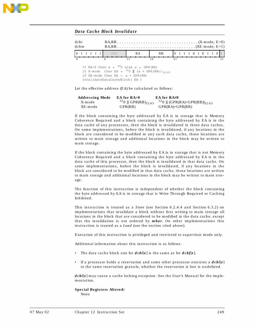
Data Cache Block Invalidate
dcbi RA,RB . . . . . . . . . . . . . . . . . . . . . . . . . . . . . . . . . . (X-mode, E=0)dcbie RA,RB . . . . . . . . . . . . . . . . . . . . . . . . . . . . . . . . . (XE-mode, E=1)
if RA=0 then a ← 640 else a ← GPR(RA)if X-mode then EA ← 320 || (a + GPR(RB)) 32:63if XE-mode then EA ← a + GPR(RB)InvalidateDataCacheBlock( EA )
Let the effective address (EA) be calculated as follows:
Addressing Mode EA for RA=0 EA for RA≠0X-mode 320 || GPR(RB)32:63
320 || (GPR(RA)+GPR(RB))32:63XE-mode GPR(RB) GPR(RA)+GPR(RB)
If the block containing the byte addressed by EA is in storage that is MemoryCoherence Required and a block containing the byte addressed by EA is in thedata cache of any processors, then the block is invalidated in those data caches.On some implementations, before the block is invalidated, if any locations in theblock are considered to be modified in any such data cache, those locations arewritten to main storage and additional locations in the block may be written tomain storage.
If the block containing the byte addressed by EA is in storage that is not MemoryCoherence Required and a block containing the byte addressed by EA is in thedata cache of this processor, then the block is invalidated in that data cache. Onsome implementations, before the block is invalidated, if any locations in theblock are considered to be modified in that data cache, those locations are writtento main storage and additional locations in the block may be written to main stor-age.
The function of this instruction is independent of whether the block containingthe byte addressed by EA is in storage that is Write Through Required or CachingInhibited.
This instruction is treated as a Store (see Section 6.2.4.4 and Section 6.3.2) onimplementations that invalidate a block without first writing to main storage alllocations in the block that are considered to be modified in the data cache, exceptthat the invalidation is not ordered by mbar. On other implementations thisinstruction is treated as a Load (see the section cited above).
Execution of this instruction is privileged and restricted to supervisor mode only.
Additional information about this instruction is as follows.
• The data cache block size for dcbi[e] is the same as for dcbf[e].
• If a processor holds a reservation and some other processor executes a dcbi[e]to the same reservation granule, whether the reservation is lost is undefined.
dcbi[e] may cause a cache locking exception. See the User’s Manual for the imple-mentation.
Special Registers Altered:None
0 1 1 1 1 1 /// RA RB 0 1 1 1 0 1 E 1 1 0 /
0 6 11 16 21 31
07 May 02 Chapter 12 Instruction Set 249

Engineering NoteIt is permissible to implement dcbi[e] as an instruction that performs the same opera-tions as dcbf[e] but is privileged.
250 Book E: Enhanced PowerPC Architecture Version 1.0 07 May 02

Data Cache Block Store
dcbst RA,RB . . . . . . . . . . . . . . . . . . . . . . . . . . . . . . . . . . (X-mode, E=0)dcbste RA,RB . . . . . . . . . . . . . . . . . . . . . . . . . . . . . . . . . (XE-mode, E=1)
if RA=0 then a ← 640 else a ← GPR(RA)if X-mode then EA ← 320 || (a + GPR(RB)) 32:63if XE-mode then EA ← a + GPR(RB)StoreDataCacheBlock( EA )
Let the effective address (EA) be calculated as follows:
Addressing Mode EA for RA=0 EA for RA≠0X-mode 320 || GPR(RB)32:63
320 || (GPR(RA)+GPR(RB))32:63XE-mode GPR(RB) GPR(RA)+GPR(RB)
If the block containing the byte addressed by EA is in storage that is MemoryCoherence Required and a block containing the byte addressed by EA is in thedata cache of any processor, and any locations in the block are considered to bemodified there, those locations are written to main storage. Additional locations inthe block may be written to main storage. The block ceases to be considered to bemodified in that data cache.
If the block containing the byte addressed by EA is in storage that is not MemoryCoherence Required and a block containing the byte addressed by EA is in thedata cache of this processor and any locations in the block are considered to bemodified there, those locations are written to main storage. Additional locations inthe block may be written to main storage. The block ceases to be considered to bemodified in that data cache.
The function of this instruction is independent of whether the block containingthe byte addressed by EA is in storage that is Write Through Required or CachingInhibited.
This instruction is treated as a Load (see Section 6.2.4.4 and Section 6.3.2).
Special Registers Altered:None
0 1 1 1 1 1 /// RA RB 0 0 0 0 1 1 E 1 1 0 /
0 6 11 16 21 31
07 May 02 Chapter 12 Instruction Set 251

Data Cache Block Touch
dcbt CT,RA,RB . . . . . . . . . . . . . . . . . . . . . . . . . . . . . . . (X-mode, E=0)dcbte CT,RA,RB . . . . . . . . . . . . . . . . . . . . . . . . . . . . . . (XE-mode, E=1)
if RA=0 then a ← 640 else a ← GPR(RA)if X-mode then EA ← 320 || (a + GPR(RB)) 32:63if XE-mode then EA ← a + GPR(RB)PrefetchDataCacheBlock( CT, EA )
Let the effective address (EA) be calculated as follows:
Addressing Mode EA for RA=0 EA for RA≠0X-mode 320 || GPR(RB)32:63
320 || (GPR(RA)+GPR(RB))32:63XE-mode GPR(RB) GPR(RA)+GPR(RB)
If CT=0, this instruction is a hint that performance will probably be improved ifthe block containing the byte addressed by EA is fetched into the data cache,because the program will probably soon load from the addressed byte.
An implementation may use other values of CT to enable software to target spe-cific, implementation-dependent ‘portions of its cache hierarchy or structure thatmay better enhance performance. See the User’s Manual for the implementation.
Implementations should perform no operation when CT specifies a value that isnot supported by the implementation.
The hint is ignored if the block is Caching Inhibited.
This instruction is treated as a Load (see Section 6.2.4.4 and Section 6.3.2),except that an interrupt is not taken for a translation or protection violation.
Special Registers Altered:None
0 1 1 1 1 1 CT RA RB 0 1 0 0 0 1 E 1 1 0 /
0 6 11 16 21 31
Engineering NotePrograms are likely to execute dcbt[e] for several blocks before executing Load or Storeinstructions that refer to the first of these blocks. Implementations on which dcbt[e]fetches the block into a separate buffer rather than directly into the data cache shouldprovide buffer space sufficient for this use.
252 Book E: Enhanced PowerPC Architecture Version 1.0 07 May 02

Data Cache Block Touch for Store
dcbtst CT,RA,RB . . . . . . . . . . . . . . . . . . . . . . . . . . . . . . . (X-mode, E=0)dcbtste CT,RA,RB . . . . . . . . . . . . . . . . . . . . . . . . . . . . . . (XE-mode, E=1)
if RA=0 then a ← 640 else a ← GPR(RA)if X-mode then EA ← 320 || (a + GPR(RB)) 32:63if XE-mode then EA ← a + GPR(RB)PrefetchForStoreDataCacheBlock( CT, EA )
Let the effective address (EA) be calculated as follows:
Addressing Mode EA for RA=0 EA for RA≠0X-mode 320 || GPR(RB)32:63
320 || (GPR(RA)+GPR(RB))32:63XE-mode GPR(RB) GPR(RA)+GPR(RB)
If CT=0, this instruction is a hint that performance will probably be improved ifthe block containing the byte addressed by EA is fetched into the data cache,because the program will probably soon store into the addressed byte.
An implementation may use other values of CT to enable software to target spe-cific, implementation-dependent portions of its cache hierarchy or structure thatmay better enhance performance. See the User’s Manual for the implementation.
Implementations should perform no operation when CT specifies a value that isnot supported by the implementation.
The hint is ignored if the block is Caching Inhibited.
This instruction is treated as a Load (see Section 6.2.4.4 and Section 6.3.2),except that an interrupt is not taken for a translation or protection violation.
Special Registers Altered:None
0 1 1 1 1 1 CT RA RB 0 0 1 1 1 1 E 1 1 0 /
0 6 11 16 21 31
Engineering NoteExecuting dcbtst[e] does not cause the specified block to be considered to be modified inthe data cache.
07 May 02 Chapter 12 Instruction Set 253

Data Cache Block set to Zero
dcbz RA,RB . . . . . . . . . . . . . . . . . . . . . . . . . . . . . . . . . . (X-mode, E=0)dcbze RA,RB . . . . . . . . . . . . . . . . . . . . . . . . . . . . . . . . . (XE-mode, E=1)
if RA=0 then a ← 640 else a ← GPR(RA)if X-mode then EA ← 320 || (a + GPR(RB)) 32:63if XE-mode then EA ← a + GPR(RB)ZeroDataCacheBlock( EA )
Let the effective address (EA) be calculated as follows:
Addressing Mode EA for RA=0 EA for RA≠0X-mode 320 || GPR(RB)32:63
320 || (GPR(RA)+GPR(RB))32:63XE-mode GPR(RB) GPR(RA)+GPR(RB)
If the block containing the byte addressed by EA is in the data cache, all bytes ofthe block are set to zero.
If the block containing the byte addressed by EA is not in the data cache and is instorage that is not Caching Inhibited, the block is established in the data cachewithout fetching the block from main storage, and all bytes of the block are set tozero.
If the block containing the byte addressed by EA is in storage that is CachingInhibited or Write Through Required, then either (a) all bytes of the area of mainstorage that corresponds to the addressed block are set to zero, or (b) an Align-ment interrupt is taken. See the User’s Manual for the implementation.
If the block containing the byte addressed by EA is in storage that is MemoryCoherence Required and the block exists in the data cache(s) of any other proces-sor(s), it is kept coherent in those caches.
This instruction may establish a block in the data cache without verifying that theassociated real address is valid. This can cause a delayed Machine Check inter-rupt, as described in Section 7.4.4, “Machine Check Interrupts,” on page 151.
This instruction is treated as a Store (see Section 6.2.4.4 and Section 6.3.2).
This instruction may cause a cache locking exception. See the User’s Manual forthe implementation.
Special Registers Altered:None
0 1 1 1 1 1 /// RA RB 1 1 1 1 1 1 E 1 1 0 /
0 6 11 16 21 31
Programming NoteIf the block containing the byte addressed by EA is in storage that is Caching Inhibitedor Write Through Required, the Alignment interrupt handler should set to zero all bytesof the area of main storage that corresponds to the addressed block.
254 Book E: Enhanced PowerPC Architecture Version 1.0 07 May 02

Divide Doubleword
divd RT,RA,RB . . . . . . . . . . . . . . . . . . . . . . . . . . . . . . . . . . . . .(OE=0)divdo RT,RA,RB . . . . . . . . . . . . . . . . . . . . . . . . . . . . . . . . . . . . .(OE=1)
dividend 0:63 ← GPR(RA)divisor 0:63 ← GPR(RB)if OE=1 then do OV64 ← ( (GPR(RA)=-2 63) & (GPR(RB)=-1) ) | (GPR(RB)=0) SO64 ← SO64 | OV64GPR(RT) ← dividend ÷ divisor
The 64-bit quotient of the contents of GPR(RA) divided by the contents of GPR(RB)is placed into GPR(RT). The remainder is not supplied as a result.
Both operands and the quotient are interpreted as signed integers. The quotient isthe unique signed integer that satisfies
dividend = (quotient × divisor) + r
where 0 ≤ r < |divisor| if the dividend is nonnegative, and –|divisor| < r ≤ 0 if thedividend is negative.
If an attempt is made to perform any of the divisions
0x8000_0000_0000_0000 ÷ -1<anything> ÷ 0
then the contents of GPR(RT) are undefined. In these cases, if OE=1 then OV is setto 1.
Special Registers Altered:SO64 OV64. . . . . . . . . . . . . . . . . . . . . . . . . . . . . . . . . . . . . . . . . . . (if OE=1)
0 1 1 1 1 1 RT RA RB OE 1 1 1 1 0 1 0 0 1 /
0 6 11 16 21 31
Programming NoteThe 64-bit signed remainder of dividing GPR(RA) by GPR(RB) can be computed as fol-lows, except in the case that GPR(RA) = –263 and GPR(RB) = –1.
divd RT,RA,RB # RT = quotient mulld RT,RT,RB # RT = quotient*divisor subf RT,RT,RA # RT = remainder
07 May 02 Chapter 12 Instruction Set 255

Divide Doubleword Unsigned
divdu RT,RA,RB . . . . . . . . . . . . . . . . . . . . . . . . . . . . . . . . . . . . .(OE=0)divduo RT,RA,RB . . . . . . . . . . . . . . . . . . . . . . . . . . . . . . . . . . . . .(OE=1)
dividend 0:63 ← GPR(RA)divisor 0:63 ← GPR(RB)quotient 0:63 ← dividend ÷ divisorif OE=1 then do OV64 ← (GPR(RB)=0) SO64 ← SO64 | OV64GPR(RT) ← quotient
The 64-bit quotient of the contents of GPR(RA) divided by the contents of GPR(RB)is placed into GPR(RT). The remainder is not supplied as a result.
Both operands and the quotient are interpreted as unsigned integers. The quo-tient is the unique unsigned integer that satisfies
dividend = (quotient × divisor) + r
where 0 ≤ r < divisor.
If an attempt is made to perform the division
<anything> ÷ 0
then the contents of GPR(RT) are undefined. In this case, if OE=1 then OV is set to1.
Special Registers Altered:SO64 OV64. . . . . . . . . . . . . . . . . . . . . . . . . . . . . . . . . . . . . . . . . . . (if OE=1)
0 1 1 1 1 1 RT RA RB OE 1 1 1 0 0 1 0 0 1 /
0 6 11 16 21 31
Programming NoteThe 64-bit unsigned remainder of dividing GPR(RA) by GPR(RB) can be computed asfollows.
divdu RT,RA,RB # RT = quotient mulld RT,RT,RB # RT = quotient*divisor subf RT,RT,RA # RT = remainder
256 Book E: Enhanced PowerPC Architecture Version 1.0 07 May 02

Divide Word
divw RT,RA,RB . . . . . . . . . . . . . . . . . . . . . . . . . . . . . . . . (OE=0, Rc=0)divw. RT,RA,RB . . . . . . . . . . . . . . . . . . . . . . . . . . . . . . . . (OE=0, Rc=1)divwo RT,RA,RB . . . . . . . . . . . . . . . . . . . . . . . . . . . . . . . . (OE=1, Rc=0)divwo. RT,RA,RB . . . . . . . . . . . . . . . . . . . . . . . . . . . . . . . . (OE=1, Rc=1)
dividend 0:31 ← GPR(RA) 32:63divisor 0:31 ← GPR(RB) 32:63quotient 0:31 ← dividend ÷ divisorif OE=1 then do OV ← ( (GPR(RA) 32:63 =-2 31) & (GPR(RB) 32:63 =-1) ) | (GPR(RB) 32:63 =0) SO ← SO | OVif Rc=1 then do
LT ← quotient < 0GT ← quotient > 0EQ ← quotient = 0CR0 ← LT || GT || EQ || SO
GPR(RT)32:63 ← quotientGPR(RT)0:31 ← undefined
The 32-bit quotient of the contents of bits 32:63 of GPR(RA) divided by the con-tents of bits 32:63 of GPR(RB) is placed into bits 32:63 of GPR(RT). Bits 0:31 ofGPR(RT) are undefined. The remainder is not supplied as a result.
Both operands and the quotient are interpreted as signed integers. The quotient isthe unique signed integer that satisfies
dividend = (quotient × divisor) + r
where 0 ≤ r < |divisor| if the dividend is nonnegative, and –|divisor| < r ≤ 0 if thedividend is negative.
If an attempt is made to perform any of the divisions
0x8000_0000 ÷ -1<anything> ÷ 0
then the contents of GPR(RT) are undefined as are (if Rc=1) the contents of the LT,GT, and EQ bits of CR Field 0. In these cases, if OE=1 then OV is set to 1.
Special Registers Altered:CR0 . . . . . . . . . . . . . . . . . . . . . . . . . . . . . . . . . . . . . . . . . . . . . . . . . .(if Rc=1)SO OV. . . . . . . . . . . . . . . . . . . . . . . . . . . . . . . . . . . . . . . . . . . . . . . (if OE=1)
0 1 1 1 1 1 RT RA RB OE 1 1 1 1 0 1 0 1 1 Rc
0 6 11 16 21 31
Programming NoteThe 32-bit signed remainder of dividing GPR(RA)32:63 by GPR(RB)32:63 can be computedas follows, except in the case that GPR(RA)32:63 = –231 and GPR(RB)32:63 = –1.
divw RT,RA,RB # RT = quotient mullw RT,RT,RB # RT = quotient*divisor subf RT,RT,RA # RT = remainder
07 May 02 Chapter 12 Instruction Set 257

Divide Word Unsigned
divwu RT,RA,RB . . . . . . . . . . . . . . . . . . . . . . . . . . . . . . . . (OE=0, Rc=0)divwu. RT,RA,RB . . . . . . . . . . . . . . . . . . . . . . . . . . . . . . . . (OE=0, Rc=1)divwuo RT,RA,RB . . . . . . . . . . . . . . . . . . . . . . . . . . . . . . . . (OE=1, Rc=0)divwuo. RT,RA,RB . . . . . . . . . . . . . . . . . . . . . . . . . . . . . . . . (OE=1, Rc=1)
dividend 0:31 ← GPR(RA) 32:63divisor 0:31 ← GPR(RB) 32:63quotient 0:31 ← dividend ÷ divisorif OE=1 then do OV ← (GPR(RB) 32:63 =0) SO ← SO | OVif Rc=1 then do
LT ← quotient < 0GT ← quotient > 0EQ ← quotient = 0CR0 ← LT || GT || EQ || SO
GPR(RT)32:63 ← quotientGPR(RT)0:31 ← undefined
The 32-bit quotient of the contents of bits 32:63 of GPR(RA) divided by the con-tents of bits 32:63 of GPR(RB) is placed into bits 32:63 of GPR(RT). Bits 0:31 ofGPR(RT) are undefined. The remainder is not supplied as a result.
Both operands and the quotient are interpreted as unsigned integers, except thatif Rc=1 the first three bits of CR Field 0 are set by signed comparison of the resultto zero. The quotient is the unique unsigned integer that satisfies
dividend = (quotient × divisor) + r
where 0 ≤ r < divisor.
If an attempt is made to perform the division
<anything> ÷ 0
then the contents of GPR(RT) are undefined as are (if Rc=1) the contents of the LT,GT, and EQ bits of CR Field 0. In this case, if OE=1 then OV is set to 1.
Special Registers Altered:CR0 . . . . . . . . . . . . . . . . . . . . . . . . . . . . . . . . . . . . . . . . . . . . . . . . . .(if Rc=1)SO OV. . . . . . . . . . . . . . . . . . . . . . . . . . . . . . . . . . . . . . . . . . . . . . . (if OE=1)
0 1 1 1 1 1 RT RA RB OE 1 1 1 0 0 1 0 1 1 Rc
0 6 11 16 21 31
Programming NoteThe 32-bit unsigned remainder of dividing GPR(RA)32:63 by GPR(RB)32:63 can be com-puted as follows.
divwu RT,RA,RB # RT = quotient mullw RT,RT,RB # RT = quotient*divisor subf RT,RT,RA # RT = remainder
258 Book E: Enhanced PowerPC Architecture Version 1.0 07 May 02

Equivalent
eqv RA,RS,RB . . . . . . . . . . . . . . . . . . . . . . . . . . . . . . . . . . . . . (Rc=0)eqv. RA,RS,RB . . . . . . . . . . . . . . . . . . . . . . . . . . . . . . . . . . . . . (Rc=1)
result 0:63 ← GPR(RS) ≡ GPR(RB)if Rc=1 then do
LT ← result 32:63 < 0GT ← result 32:63 > 0EQ ← result 32:63 = 0CR0 ← LT || GT || EQ || SO
GPR(RA) ← result
The contents of GPR(RS) are XORed with the contents of GPR(RB) and the one’scomplement of the result is placed into GPR(RA).
Special Registers Altered:CR0 . . . . . . . . . . . . . . . . . . . . . . . . . . . . . . . . . . . . . . . . . . . . . . . . . .(if Rc=1)
0 1 1 1 1 1 RS RA RB 0 1 0 0 0 1 1 1 0 0 Rc
0 6 11 16 21 31
07 May 02 Chapter 12 Instruction Set 259

Extend Sign (Byte | Halfword | Word)
extsb RA,RS . . . . . . . . . . . . . . . . . . . . . . . . . . . . . . . . (SZ=0b01, Rc=0)extsb. RA,RS . . . . . . . . . . . . . . . . . . . . . . . . . . . . . . . . (SZ=0b01, Rc=1)
extsh RA,RS . . . . . . . . . . . . . . . . . . . . . . . . . . . . . . . . (SZ=0b00, Rc=0)extsh. RA,RS . . . . . . . . . . . . . . . . . . . . . . . . . . . . . . . . (SZ=0b00, Rc=1)
extsw RA,RS . . . . . . . . . . . . . . . . . . . . . . . . . . . . . . . . (SZ=0b10, Rc=0)
if ‘extsb[.]’ then n ← 56if ‘extsh[.]’ then n ← 48if ‘extsw’ then n ← 32if Rc=1 then do
LT ← GPR(RS) n:63 < 0GT ← GPR(RS) n:63 > 0EQ ← GPR(RS) n:63 = 0CR0 ← LT || GT || EQ || SO
s ← GPR(RS) nGPR(RA) ← ns || GPR(RS) n:63
For extsb[.], the contents of bits 56:63 of GPR(RS) are placed into bits 56:63 ofGPR(RA). Bit 56 of the contents of GPR(RS) is copied into bits 0:55 of GPR(RA). IfRc=1, CR Field 0 is set to reflect the result.
For extsh[.], the contents of bits 48:63 of GPR(RS) are placed into bits 48:63 ofGPR(RA). Bit 48 of the contents of GPR(RS) is copied into bits 0:47 of GPR(RA). IfRc=1, CR Field 0 is set to reflect the result.
For extsw, the contents of bits 32:63 of GPR(RS) are placed into the contents ofbits 32:63 of GPR(RA). Bit 32 of the contents of GPR(RS) is copied into bits 0:31 ofGPR(RA). If Rc=1, the instruction form is invalid.
Special Registers Altered:CR0 . . . . . . . . . . . . . . . . . . . . . . . . . . . . . . . . . . . . . . . . . . . . . . . . . .(if Rc=1)
0 1 1 1 1 1 RS RA /// 1 1 1 S Z 1 1 0 1 0 Rc
0 6 11 16 21 31
260 Book E: Enhanced PowerPC Architecture Version 1.0 07 May 02

Floating Absolute Value
fabs FRT,FRB . . . . . . . . . . . . . . . . . . . . . . . . . . . . . . . . . . . . . . (Rc=0)fabs. FRT,FRB . . . . . . . . . . . . . . . . . . . . . . . . . . . . . . . . . . . . . . (Rc=1)
FPR(FRT) ← 0b0 ||FPR(FRB) 1:63
The contents of FPR(FRB) with bit 0 set to zero are placed into FPR(FRT).
An attempt to execute fabs[.] while MSRFP=0 will cause a Floating-Point Unavail-able interrupt.
Special Registers Altered:CR1 ← FX || FEX || VX || OX . . . . . . . . . . . . . . . . . . . . . . . . . . . . . .(if Rc=1)
1 1 1 1 1 1 FRT /// FRB 0 1 0 0 0 0 1 0 0 0 Rc
0 6 11 16 21 31
07 May 02 Chapter 12 Instruction Set 261

Floating Add [Single]
fadd FRT,FRA,FRB . . . . . . . . . . . . . . . . . . . . . . . . . . . . . . (P=1, Rc=0)fadd. FRT,FRA,FRB . . . . . . . . . . . . . . . . . . . . . . . . . . . . . . (P=1, Rc=1)
fadds FRT,FRA,FRB . . . . . . . . . . . . . . . . . . . . . . . . . . . . . . (P=0, Rc=0)fadds. FRT,FRA,FRB . . . . . . . . . . . . . . . . . . . . . . . . . . . . . . (P=0, Rc=1)
if P=1 then FPR(FRT) ← FPR(FRA) + dp FPR(FRB)else FPR(FRT) ← FPR(FRA) + sp FPR(FRB)
The floating-point operand in FPR(FRA) is added to the floating-point operand inFPR(FRB).
If the most significant bit of the resultant significand is not 1, the result is nor-malized. The result is rounded to the target precision under control of the Float-ing-Point Rounding Control field RN of the Floating-Point Status and ControlRegister and placed into FPR(FRT).
Floating-point addition is based on exponent comparison and addition of the twosignificands. The exponents of the two operands are compared, and the signifi-cand accompanying the smaller exponent is shifted right, with its exponentincreased by one for each bit shifted, until the two exponents are equal. The twosignificands are then added or subtracted as appropriate, depending on the signsof the operands, to form an intermediate sum. All 53 bits of the significand as wellas all three guard bits (G, R, and X) enter into the computation.
If a carry occurs, the sum's significand is shifted right one bit position and theexponent is increased by one.
FPSCRFPRF is set to the class and sign of the result, except for Invalid OperationExceptions when FPSCRVE=1.
An attempt to execute fadd[s][.] while MSRFP=0 will cause a Floating-PointUnavailable interrupt.
Special Registers Altered:FPRF FR FI FX OX UX XX VXSNAN VXISICR1 ← FX || FEX || VX || OX . . . . . . . . . . . . . . . . . . . . . . . . . . . . . .(if Rc=1)
1 1 1 P 1 1 FRT FRA FRB /// 1 0 1 0 1 Rc
0 6 11 16 21 26 31
262 Book E: Enhanced PowerPC Architecture Version 1.0 07 May 02

Floating Convert From Integer Doubleword
fcfid FRT,FRB
sign ← FPR(FRB)0exp ← 63frac0:63 ← FPR(FRB)If frac0:63 = 0 then go to Zero OperandIf sign = 1 then frac0:63 ← ¬frac0:63 + 1Do while frac0 = 0 /* do loop 0 times if FPR(FRB) = max negative integer */
frac0:63 ← frac1:63 || 0b0exp ← exp – 1
End
Round Float( sign, exp, frac0:63, FPSCRRN )
If sign = 0 then FPSCRFPRF ← ‘+normal number’If sign = 1 then FPSCRFPRF ← ‘–normal number’FPR(FRT)0 ← signFPR(FRT)1:11 ← exp + 1023 /* exp + bias */FPR(FRT)12:63 ← frac1:52Done
Zero Operand:FPSCRFR FI ← 0b00FPSCRFPRF ← ‘+zero’FPR(FRT) ← 0x0000_0000_0000_0000Done
Round Float( sign, exp, frac0:63, round_mode ):inc ← 0lsb ← frac52gbit ← frac53rbit ← frac54xbit ← frac55:63 > 0If round_mode = 0b00 then
Do /* comparison ignores u bits */If sign || lsb || gbit || rbit || xbit = 0bu11uu then inc ← 1If sign || lsb || gbit || rbit || xbit = 0bu011u then inc ← 1If sign || lsb || gbit || rbit || xbit = 0bu01u1 then inc ← 1
EndIf round_mode = 0b10 then
Do /* comparison ignores u bits */If sign || lsb || gbit || rbit || xbit = 0b0u1uu then inc ← 1If sign || lsb || gbit || rbit || xbit = 0b0uu1u then inc ← 1If sign || lsb || gbit || rbit || xbit = 0b0uuu1 then inc ← 1
EndIf round_mode = 0b11 then
Do /* comparison ignores u bits */If sign || lsb || gbit || rbit || xbit = 0b1u1uu then inc ← 1If sign || lsb || gbit || rbit || xbit = 0b1uu1u then inc ← 1If sign || lsb || gbit || rbit || xbit = 0b1uuu1 then inc ← 1
Endfrac0:52 ← frac0:52 + incIf carry_out = 1 then exp ← exp + 1FPSCRFR ← incFPSCRFI ← gbit | rbit | xbitFPSCRXX ← FPSCRXX | FPSCRFIReturn
The 64-bit signed operand in FPR(FRB) is converted to an infinitely precise float-ing-point integer. The result of the conversion is rounded to double-precision,using the rounding mode specified by FPSCRRN, and placed into FPR(FRT).
FPSCRFPRF is set to the class and sign of the result. FPSCRFR is set if the result isincremented when rounded. FPSCRFI is set if the result is inexact.
1 1 1 1 1 1 FRT /// FRB 1 1 0 1 0 0 1 1 1 0 /
0 6 11 16 21 31
07 May 02 Chapter 12 Instruction Set 263

An attempt to execute fcfid while MSRFP=0 will cause a Floating-Point Unavail-able interrupt.
Special Registers Altered:FPRF FR FI FX XX
264 Book E: Enhanced PowerPC Architecture Version 1.0 07 May 02

Floating Compare
fcmpu BF,FRA,FRB . . . . . . . . . . . . . . . . . . . . . . . . . . . . . . . . . . . . (U=0)fcmpo BF,FRA,FRB . . . . . . . . . . . . . . . . . . . . . . . . . . . . . . . . . . . . (U=1)
if FPR(FRA) is a NaN or FPR(FRB) is a NaN then c ← 0b0001else if FPR(FRA) < FPR(FRB) then c ← 0b1000else if FPR(FRA) > FPR(FRB) then c ← 0b0100else c ← 0b0010FPCC ← cCR4×BF:4 ×BF+3 ← cif ‘fcmpu’ then do if FPR(FRA) is a SNaN or FPR(FRB) is a SNaN then VXSNAN ← 1if ‘fcmpo’ then do if FPR(FRA) is a SNaN or FPR(FRB) is a SNaN then do VXSNAN ← 1 if VE=0 then VXVC ← 1 else if FPR(FRA) is a QNaN or FPR(FRB) is a QNaN then VXVC ← 1
The floating-point operand in FPR(FRA) is compared to the floating-point operandin FPR(FRB). The result of the compare is placed into CR field BF and the FPCC.
If either of the operands is a NaN, either quiet or signaling, then CR field BF andthe FPCC are set to reflect unordered.
If fcmpu then if either of the operands is a Signaling NaN, then VXSNAN is set.
If fcmpo then do the following:If either of the operands is a Signaling NaN and Invalid Operation is disabled(VE=0), VXVC is set and VXSNAN is set. If neither operand is a Signaling NaNbut at least one operand is a Quiet NaN, then VXVC is set.
An attempt to execute fcmpo or fcmpu while MSRFP=0 will cause a Floating-PointUnavailable interrupt.
Special Registers Altered:CR field BFFPCC FX VXSNANVXVC . . . . . . . . . . . . . . . . . . . . . . . . . . . . . . . . . . . . . . . . . . . . . . . (if fcmpo)
1 1 1 1 1 1 BF // FRA FRB 0 0 0 0 U 0 0 0 0 0 /
0 6 9 11 16 21 31
07 May 02 Chapter 12 Instruction Set 265

Floating Convert To Integer Doubleword
fctid FRT,FRB . . . . . . . . . . . . . . . . . . . . . . . . . . . . . . . . . . . . . . . (Z=0)fctidz FRT,FRB . . . . . . . . . . . . . . . . . . . . . . . . . . . . . . . . . . . . . . . (Z=1)
if ‘fctid[.]’ then round_mode ← FPSCRRNif ‘fctidz[.]’ then round_mode ← 0b01sign ← FPR(FRB)0If FPR(FRB)1:11 = 2047 and FPR(FRB)12:63 = 0 then goto Infinity OperandIf FPR(FRB)1:11 = 2047 and FPR(FRB)12 = 0 then goto SNaN OperandIf FPR(FRB)1:11 = 2047 and FPR(FRB)12 = 1 then goto QNaN OperandIf FPR(FRB)1:11 > 1086 then goto Large OperandIf FPR(FRB)1:11 > 0 then exp ← FPR(FRB)1:11 – 1023 /* exp – bias */If FPR(FRB)1:11 = 0 then exp ← –1022
/* normal; need leading 0 for later complement */If FPR(FRB)1:11 > 0 then frac0:64 ← 0b01 || FPR(FRB)12:63 || 110
/* denormal */If FPR(FRB)1:11 = 0 then frac0:64 ← 0b00 || FPR(FRB)12:63 || 110
gbit || rbit || xbit ← 0b000Do i=1,63–exp /* do the loop 0 times if exp = 63 */
frac0:64 || gbit || rbit || xbit ← 0b0 || frac0:64 || gbit || (rbit | xbit)End
Round Integer( sign, frac0:64, gbit, rbit, xbit, round_mode )
/* needed leading 0 for –264 < FPR(FRB) < –263 */If sign=1 then frac0:64 ← ¬frac0:64 + 1
If frac0:64 > 263–1 then goto Large OperandIf frac0:64 < –263 then goto Large Operand
FPSCRXX ← FPSCRXX | FPSCRFIFPSCRFPRF ← undefinedFPR(FRT) ← frac1:64Done
Round Integer( sign,frac0:64, gbit, rbit, xbit, round_mode ):inc ← 0If round_mode = 0b00 then /* comparison ignores u bits */
DoIf sign || frac64 || gbit || rbit || xbit = 0bu11uu then inc ← 1If sign || frac64 || gbit || rbit || xbit = 0bu011u then inc ← 1If sign || frac64 || gbit || rbit || xbit = 0bu01u1 then inc ← 1
End
If round_mode = 0b10 then /* comparison ignores u bits */Do
If sign || frac64 || gbit || rbit || xbit = 0b0u1uu then inc ← 1If sign || frac64 || gbit || rbit || xbit = 0b0uu1u then inc ← 1If sign || frac64 || gbit || rbit || xbit = 0b0uuu1 then inc ← 1
EndIf round_mode = 0b11 then /* comparison ignores u bits */
DoIf sign || frac64 || gbit || rbit || xbit = 0b1u1uu then inc ← 1If sign || frac64 || gbit || rbit || xbit = 0b1uu1u then inc ← 1If sign || frac64 || gbit || rbit || xbit = 0b1uuu1 then inc ← 1
End
frac0:64 ← frac0:64 + incFPSCRFR ← incFPSCRFI ← gbit | rbit | xbitReturn
Infinity Operand:FPSCRFR FI VXCVI ← 0b001If FPSCRVE = 0 then Do
If sign = 0 then FPR(FRT) ← 0x7FFF_FFFF_FFFF_FFFF
1 1 1 1 1 1 FRT /// FRB 1 1 0 0 1 0 1 1 1 Z /
0 6 11 16 21 31
266 Book E: Enhanced PowerPC Architecture Version 1.0 07 May 02

If sign = 1 then FPR(FRT) ← 0x8000_0000_0000_0000FPSCRFPRF ← undefined
EndDone
SNaN Operand:FPSCRFR FI VXSNAN VXCVI ← 0b0011If FPSCRVE = 0 then Do
FPR(FRT) ← 0x8000_0000_0000_0000FPSCRFPRF ← undefined
EndDone
QNaN Operand:FPSCRFR FI VXCVI ← 0b001If FPSCRVE = 0 then Do
FPR(FRT) ← 0x8000_0000_0000_0000FPSCRFPRF ← undefined
EndDone
Large Operand:FPSCRFR FI VXCVI ← 0b001If FPSCRVE = 0 then Do
If sign = 0 then FPR(FRT) ← 0x7FFF_FFFF_FFFF_FFFFIf sign = 1 then FPR(FRT) ← 0x8000_0000_0000_0000FPSCRFPRF ← undefined
EndDone
For fctid or fctid., the rounding mode is specified by FPSCRRN.For fctidz or fctidz., the rounding mode used is Round toward Zero.
The floating-point operand in FPR(FRB) is converted to a 64-bit signed integer,using the rounding mode specified by the instruction, and placed into FPR(FRT).
If the floating-point operand in FPR(FRB) is greater than 263–1, then0x7FFF_FFFF_FFFF_FFFF is placed into FPR(FRT). If the floating-point operandin FPR(FRB) is less than –263, then 0x8000_0000_0000_0000 is placed intoFPR(FRT).
Except for enabled Invalid Operation Exceptions, FPSCRFPRF is undefined.FPSCRFR is set if the result is incremented when rounded. FPSCRFI is set if theresult is inexact.
An attempt to execute fctid[z] while MSRFP=0 will cause a Floating-Point Unavail-able interrupt.
Special Registers Altered:FPRF (undefined) FR FI FX XX VXSNAN VXCVI
07 May 02 Chapter 12 Instruction Set 267

Floating Convert To Integer Word
fctiw FRT,FRB . . . . . . . . . . . . . . . . . . . . . . . . . . . . . . . . . . (Z=0, Rc=0)fctiw. FRT,FRB . . . . . . . . . . . . . . . . . . . . . . . . . . . . . . . . . . (Z=0, Rc=1)
fctiwz FRT,FRB . . . . . . . . . . . . . . . . . . . . . . . . . . . . . . . . . . (Z=1, Rc=0)fctiwz. FRT,FRB . . . . . . . . . . . . . . . . . . . . . . . . . . . . . . . . . . (Z=1, Rc=1)
if ‘fctiw[.]’ then round_mode ← FPSCRRNif ‘fctiwz[.]’ then round_mode ← 0b01sign ← FPR(FRB)0If FPR(FRB)1:11 = 2047 and FPR(FRB)12:63 = 0 then goto Infinity OperandIf FPR(FRB)1:11 = 2047 and FPR(FRB)12 = 0 then goto SNaN OperandIf FPR(FRB)1:11 = 2047 and FPR(FRB)12 = 1 then goto QNaN OperandIf FPR(FRB)1:11 > 1086 then goto Large OperandIf FPR(FRB)1:11 > 0 then exp ← FPR(FRB)1:11 – 1023 /* exp – bias */If FPR(FRB)1:11 = 0 then exp ← –1022
/* normal; need leading 0 for later complement */If FPR(FRB)1:11 > 0 then frac0:64 ← 0b01 || FPR(FRB)12:63 || 110
/* denormal */If FPR(FRB)1:11 = 0 then frac0:64 ← 0b00 || FPR(FRB)12:63 || 110gbit || rbit || xbit ← 0b000Do i=1,63–exp /* do the loop 0 times if exp = 63 */
frac0:64 || gbit || rbit || xbit ← 0b0 || frac0:64 || gbit || (rbit | xbit)End
Round Integer( sign, frac0:64, gbit, rbit, xbit, round_mode )
/* needed leading 0 for –264 < FPR(FRB) < –263 */If sign=1 then frac0:64 ← ¬frac0:64 + 1
If frac0:64 > 231–1 then goto Large OperandIf frac0:64 < –231 then goto Large Operand
FPSCRXX ← FPSCRXX | FPSCRFI
FPR(FRT) ← 0xuuuu_uuuu || frac33:64 /* u is undefined hex digit */FPSCRFPRF ← undefinedDone
Round Integer( sign, frac0:64, gbit, rbit, xbit, round_mode ):inc ← 0If round_mode = 0b00 then /* comparison ignores u bits */
DoIf sign || frac64 || gbit || rbit || xbit = 0bu11uu then inc ← 1If sign || frac64 || gbit || rbit || xbit = 0bu011u then inc ← 1If sign || frac64 || gbit || rbit || xbit = 0bu01u1 then inc ← 1
EndIf round_mode = 0b10 then /* comparison ignores u bits */
DoIf sign || frac64 || gbit || rbit || xbit = 0b0u1uu then inc ← 1If sign || frac64 || gbit || rbit || xbit = 0b0uu1u then inc ← 1If sign || frac64 || gbit || rbit || xbit = 0b0uuu1 then inc ← 1
End
If round_mode = 0b11 then /* comparison ignores u bits */Do
If sign || frac64 || gbit || rbit || xbit = 0b1u1uu then inc ← 1If sign || frac64 || gbit || rbit || xbit = 0b1uu1u then inc ← 1If sign || frac64 || gbit || rbit || xbit = 0b1uuu1 then inc ← 1
End
frac0:64 ← frac0:64 + incFPSCRFR ← incFPSCRFI ← gbit | rbit | xbitReturn
1 1 1 1 1 1 FRT /// FRB 0 0 0 0 0 0 1 1 1 Z Rc
0 6 11 16 21 31
268 Book E: Enhanced PowerPC Architecture Version 1.0 07 May 02

Infinity Operand:FPSCRFR FI VXCVI ← 0b001If FPSCRVE = 0 then Do /* u is undefined hex digit */
If sign = 0 then FPR(FRT) ← 0xuuuu_uuuu_7FFF_FFFFIf sign = 1 then FPR(FRT) ← 0xuuuu_uuuu_8000_0000FPSCRFPRF ← undefined
EndDone
SNaN Operand:FPSCRFR FI VXSNAN VXCVI ← 0b0011If FPSCRVE = 0 then Do /* u is undefined hex digit */
FPR(FRT) ← 0xuuuu_uuuu_8000_0000FPSCRFPRF ← undefined
EndDone
QNaN Operand:FPSCRFR FI VXCVI ← 0b001If FPSCRVE = 0 then Do /* u is undefined hex digit */
FPR(FRT) ← 0xuuuu_uuuu_8000_0000FPSCRFPRF ← undefined
EndDone
Large Operand:FPSCRFR FI VXCVI ← 0b001If FPSCRVE = 0 then Do /* u is undefined hex digit */
If sign = 0 then FPR(FRT) ← 0xuuuu_uuuu_7FFF_FFFFIf sign = 1 then FPR(FRT) ← 0xuuuu_uuuu_8000_0000FPSCRFPRF ← undefined
EndDone
For fctiw or fctiw., the rounding mode is specified by FPSCRRN.For fctiwz or fctiwz., the rounding mode used is Round toward Zero.
The floating-point operand in FPR(FRB) is converted to a 32-bit signed integer,using the rounding mode specified by the instruction, and placed into bits 32:63of FPR(FRT). Bits 0:31 of FPR(FRT) are undefined.
If the operand in FPR(FRB) is greater than 231–1, then bits 32:63 of FPR(FRT) areset to 0x7FFF_FFFF. If the operand in FPR(FRB) is less than –231, then bits 32:63of FPR(FRT) are set to 0x8000_0000.
Except for enabled Invalid Operation Exceptions, FPSCRFPRF is undefined.FPSCRFR is set if the result is incremented when rounded. FPSCRFI is set if theresult is inexact.
An attempt to execute fctiw[z][.] while MSRFP=0 will cause a Floating-PointUnavailable interrupt.
Special Registers Altered:FPRF (undefined) FR FI FX XX VXSNAN VXCVICR1 ← FX || FEX || VX || OX . . . . . . . . . . . . . . . . . . . . . . . . . . . . . .(if Rc=1)
07 May 02 Chapter 12 Instruction Set 269

Floating Divide [Single]
fdiv FRT,FRA,FRB . . . . . . . . . . . . . . . . . . . . . . . . . . . . . . (P=1, Rc=0)fdiv. FRT,FRA,FRB . . . . . . . . . . . . . . . . . . . . . . . . . . . . . . (P=1, Rc=1)
fdivs FRT,FRA,FRB . . . . . . . . . . . . . . . . . . . . . . . . . . . . . . (P=0, Rc=0)fdivs. FRT,FRA,FRB . . . . . . . . . . . . . . . . . . . . . . . . . . . . . . (P=0, Rc=1)
if P=1 then FPR(FRT) ← FPR(FRA) ÷dp FPR(FRB)else FPR(FRT) ← FPR(FRA) ÷sp FPR(FRB)
The floating-point operand in FPR(FRA) is divided by the floating-point operand inFPR(FRB). The remainder is not supplied as a result.
If the most significant bit of the resultant significand is not 1, the result is nor-malized. The result is rounded to the target precision under control of the Float-ing-Point Rounding Control field RN of the Floating-Point Status and ControlRegister and placed into FPR(FRT).
Floating-point division is based on exponent subtraction and division of the signif-icands.
FPSCRFPRF is set to the class and sign of the result, except for Invalid OperationExceptions when FPSCRVE=1 and Zero Divide Exceptions when FPSCRZE=1.
An attempt to execute fdiv[s][.] while MSRFP=0 will cause a Floating-PointUnavailable interrupt.
Special Registers Altered:FPRF FR FI FX OX UX ZX XX VXSNAN VXIDI VXZDZCR1 ← FX || FEX || VX || OX . . . . . . . . . . . . . . . . . . . . . . . . . . . . . .(if Rc=1)
1 1 1 P 1 1 FRT FRA FRB /// 1 0 0 1 0 Rc
0 6 11 16 21 26 31
270 Book E: Enhanced PowerPC Architecture Version 1.0 07 May 02

Floating Multiply-Add [Single]
fmadd FRT,FRA,FRC,FRB . . . . . . . . . . . . . . . . . . . . . . . . . . (P=1, Rc=0)fmadd. FRT,FRA,FRC,FRB . . . . . . . . . . . . . . . . . . . . . . . . . . (P=1, Rc=1)
fmadds FRT,FRA,FRC,FRB . . . . . . . . . . . . . . . . . . . . . . . . . . (P=0, Rc=0)fmadds. FRT,FRA,FRC,FRB . . . . . . . . . . . . . . . . . . . . . . . . . . (P=0, Rc=1)
if P=1 then FPR(FRT) ← [FPR(FRA) ×fp FPR(FRC)] + dp FPR(FRB)else FPR(FRT) ← [FPR(FRA) ×fp FPR(FRC)] + sp FPR(FRB)
The floating-point operand in FPR(FRA) is multiplied by the floating-point operandin FPR(FRC). The floating-point operand in FPR(FRB) is added to this intermediateresult.
If the most significant bit of the resultant significand is not 1, the result is nor-malized. The result is rounded to the target precision under control of the Float-ing-Point Rounding Control field RN of the Floating-Point Status and ControlRegister and placed into FPR(FRT).
FPSCRFPRF is set to the class and sign of the result, except for Invalid OperationExceptions when FPSCRVE=1.
An attempt to execute fmadd[s][.] while MSRFP=0 will cause a Floating-PointUnavailable interrupt.
Special Registers Altered:FPRF FR FI FX OX UX XX VXSNAN VXISI VXIMZCR1 ← FX || FEX || VX || OX . . . . . . . . . . . . . . . . . . . . . . . . . . . . . .(if Rc=1)
1 1 1 P 1 1 FRT FRA FRB FRC 1 1 1 0 1 Rc
0 6 11 16 21 26 31
07 May 02 Chapter 12 Instruction Set 271

Floating Move Register
fmr FRT,FRB . . . . . . . . . . . . . . . . . . . . . . . . . . . . . . . . . . . . . . (Rc=0)fmr. FRT,FRB . . . . . . . . . . . . . . . . . . . . . . . . . . . . . . . . . . . . . . (Rc=1)
FPR(FRT) ← FPR(FRB)
The contents of FPR(FRB) are placed into FPR(FRT).
An attempt to execute fmr[.] while MSRFP=0 will cause a Floating-Point Unavail-able interrupt.
Special Registers Altered:CR1 ← FX || FEX || VX || OX . . . . . . . . . . . . . . . . . . . . . . . . . . . . . .(if Rc=1)
1 1 1 1 1 1 FRT /// FRB 0 0 0 1 0 0 1 0 0 0 Rc
0 6 11 16 21 31
272 Book E: Enhanced PowerPC Architecture Version 1.0 07 May 02

Floating Multiply-Subtract [Single]
fmsub FRT,FRA,FRC,FRB . . . . . . . . . . . . . . . . . . . . . . . . . . (P=1, Rc=0)fmsub. FRT,FRA,FRC,FRB . . . . . . . . . . . . . . . . . . . . . . . . . . (P=1, Rc=1)
fmsubs FRT,FRA,FRC,FRB . . . . . . . . . . . . . . . . . . . . . . . . . . (P=0, Rc=0)fmsubs. FRT,FRA,FRC,FRB . . . . . . . . . . . . . . . . . . . . . . . . . . (P=0, Rc=1)
if P=1 then FPR(FRT) ← [FPR(FRA) ×fp FPR(FRC)] - dp FPR(FRB)else FPR(FRT) ← [FPR(FRA) ×fp FPR(FRC)] - sp FPR(FRB)
The floating-point operand in FPR(FRA) is multiplied by the floating-point operandin FPR(FRC). The floating-point operand in FPR(FRB) is subtracted from thisintermediate result.
If the most significant bit of the resultant significand is not 1, the result is nor-malized. The result is rounded to the target precision under control of the Float-ing-Point Rounding Control field RN of the Floating-Point Status and ControlRegister and placed into FPR(FRT).
FPSCRFPRF is set to the class and sign of the result, except for Invalid OperationExceptions when FPSCRVE=1.
An attempt to execute fmsub[s][.] while MSRFP=0 will cause a Floating-PointUnavailable interrupt.
Special Registers Altered:FPRF FR FI FX OX UX XX VXSNAN VXISI VXIMZCR1 ← FX || FEX || VX || OX . . . . . . . . . . . . . . . . . . . . . . . . . . . . . .(if Rc=1)
1 1 1 P 1 1 FRT FRA FRB FRC 1 1 1 0 0 Rc
0 6 11 16 21 26 31
07 May 02 Chapter 12 Instruction Set 273

Floating Multiply [Single]
fmul FRT,FRA,FRC . . . . . . . . . . . . . . . . . . . . . . . . . . . . . . (P=1, Rc=0)fmul. FRT,FRA,FRC . . . . . . . . . . . . . . . . . . . . . . . . . . . . . . (P=1, Rc=1)
fmuls FRT,FRA,FRC . . . . . . . . . . . . . . . . . . . . . . . . . . . . . . (P=0, Rc=0)fmuls. FRT,FRA,FRC . . . . . . . . . . . . . . . . . . . . . . . . . . . . . . (P=0, Rc=1)
if P=1 then FPR(FRT) ← FPR(FRA) ×dp FPR(FRC)else FPR(FRT) ← FPR(FRA) ×sp FPR(FRC)
The floating-point operand in FPR(FRA) is multiplied by the floating-point operandin FPR(FRC).
If the most significant bit of the resultant significand is not 1, the result is nor-malized. The result is rounded to the target precision under control of the Float-ing-Point Rounding Control field RN of the Floating-Point Status and ControlRegister and placed into FPR(FRT).
Floating-point multiplication is based on exponent addition and multiplication ofthe significands.
FPSCRFPRF is set to the class and sign of the result, except for Invalid OperationExceptions when FPSCRVE=1.
An attempt to execute fmul[s][.] while MSRFP=0 will cause a Floating-PointUnavailable interrupt.
Special Registers Altered:FPRF FR FI FX OX UX XX VXSNAN VXIMZCR1 ← FX || FEX || VX || OX . . . . . . . . . . . . . . . . . . . . . . . . . . . . . .(if Rc=1)
1 1 1 P 1 1 FRT FRA /// FRC 1 1 0 0 1 Rc
0 6 11 16 21 26 31
274 Book E: Enhanced PowerPC Architecture Version 1.0 07 May 02
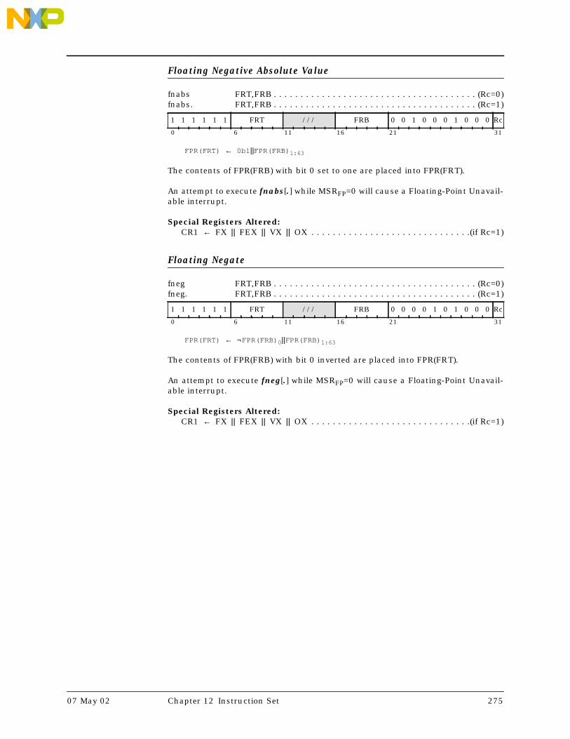
Floating Negative Absolute Value
fnabs FRT,FRB . . . . . . . . . . . . . . . . . . . . . . . . . . . . . . . . . . . . . . (Rc=0)fnabs. FRT,FRB . . . . . . . . . . . . . . . . . . . . . . . . . . . . . . . . . . . . . . (Rc=1)
FPR(FRT) ← 0b1 ||FPR(FRB) 1:63
The contents of FPR(FRB) with bit 0 set to one are placed into FPR(FRT).
An attempt to execute fnabs[.] while MSRFP=0 will cause a Floating-Point Unavail-able interrupt.
Special Registers Altered:CR1 ← FX || FEX || VX || OX . . . . . . . . . . . . . . . . . . . . . . . . . . . . . .(if Rc=1)
Floating Negate
fneg FRT,FRB . . . . . . . . . . . . . . . . . . . . . . . . . . . . . . . . . . . . . . (Rc=0)fneg. FRT,FRB . . . . . . . . . . . . . . . . . . . . . . . . . . . . . . . . . . . . . . (Rc=1)
FPR(FRT) ← ¬FPR(FRB) 0||FPR(FRB) 1:63
The contents of FPR(FRB) with bit 0 inverted are placed into FPR(FRT).
An attempt to execute fneg[.] while MSRFP=0 will cause a Floating-Point Unavail-able interrupt.
Special Registers Altered:CR1 ← FX || FEX || VX || OX . . . . . . . . . . . . . . . . . . . . . . . . . . . . . .(if Rc=1)
1 1 1 1 1 1 FRT /// FRB 0 0 1 0 0 0 1 0 0 0 Rc
0 6 11 16 21 31
1 1 1 1 1 1 FRT /// FRB 0 0 0 0 1 0 1 0 0 0 Rc
0 6 11 16 21 31
07 May 02 Chapter 12 Instruction Set 275

Floating Negative Multiply-Add [Single]
fnmadd FRT,FRA,FRC,FRB . . . . . . . . . . . . . . . . . . . . . . . . . . (P=1, Rc=0)fnmadd. FRT,FRA,FRC,FRB . . . . . . . . . . . . . . . . . . . . . . . . . . (P=1, Rc=1)
fnmadds FRT,FRA,FRC,FRB . . . . . . . . . . . . . . . . . . . . . . . . . . (P=0, Rc=0)fnmadds. FRT,FRA,FRC,FRB . . . . . . . . . . . . . . . . . . . . . . . . . . (P=0, Rc=1)
if P=1 then FPR(FRT) ← -([FPR(FRA) ×fp FPR(FRC)] + dp FPR(FRB))else FPR(FRT) ← -([FPR(FRA) ×fp FPR(FRC)] + sp FPR(FRB))
The floating-point operand in FPR(FRA) is multiplied by the floating-point operandin FPR(FRC). The floating-point operand in FPR(FRB) is added to this intermediateresult.
If the most significant bit of the resultant significand is not 1, the result is nor-malized. The result is rounded to the target precision under control of the Float-ing-Point Rounding Control field RN of the Floating-Point Status and ControlRegister, then negated and placed into FPR(FRT).
This instruction produces the same result as would be obtained by using theFloating Multiply-Add instruction and then negating the result, with the followingexceptions.
• QNaNs propagate with no effect on their ‘sign’ bit.
• QNaNs that are generated as the result of a disabled Invalid Operation Excep-tion have a ‘sign’ bit of 0.
• SNaNs that are converted to QNaNs as the result of a disabled Invalid Opera-tion Exception retain the ‘sign’ bit of the SNaN.
FPSCRFPRF is set to the class and sign of the result, except for Invalid OperationExceptions when FPSCRVE=1.
An attempt to execute fnmadd[s][.] while MSRFP=0 will cause a Floating-PointUnavailable interrupt.
Special Registers Altered:FPRF FR FI FX OX UX XX VXSNAN VXISI VXIMZCR1 ← FX || FEX || VX || OX . . . . . . . . . . . . . . . . . . . . . . . . . . . . . .(if Rc=1)
1 1 1 P 1 1 FRT FRA FRB FRC 1 1 1 1 1 Rc
0 6 11 16 21 26 31
276 Book E: Enhanced PowerPC Architecture Version 1.0 07 May 02

Floating Negative Multiply-Subtract [Single]
fnmsub FRT,FRA,FRC,FRB . . . . . . . . . . . . . . . . . . . . . . . . . . (P=1, Rc=0)fnmsub. FRT,FRA,FRC,FRB . . . . . . . . . . . . . . . . . . . . . . . . . . (P=1, Rc=1)
fnmsubs FRT,FRA,FRC,FRB . . . . . . . . . . . . . . . . . . . . . . . . . . (P=0, Rc=0)fnmsubs. FRT,FRA,FRC,FRB . . . . . . . . . . . . . . . . . . . . . . . . . . (P=0, Rc=1)
if P=1 then FPR(FRT) ← -([FPR(FRA) ×fp FPR(FRC)] – dp FPR(FRB))else FPR(FRT) ← -([FPR(FRA) ×fp FPR(FRC)] – sp FPR(FRB))
The floating-point operand in FPR(FRA) is multiplied by the floating-point operandin FPR(FRC). The floating-point operand in FPR(FRB) is subtracted from thisintermediate result.
If the most significant bit of the resultant significand is not 1, the result is nor-malized. The result is rounded to the target precision under control of the Float-ing-Point Rounding Control field RN of the Floating-Point Status and ControlRegister, then negated and placed into FPR(FRT).
This instruction produces the same result as would be obtained by using theFloating Multiply-Subtract instruction and then negating the result, with the fol-lowing exceptions.
• QNaNs propagate with no effect on their ‘sign’ bit.
• QNaNs that are generated as the result of a disabled Invalid Operation Excep-tion have a ‘sign’ bit of 0.
• SNaNs that are converted to QNaNs as the result of a disabled Invalid Opera-tion Exception retain the ‘sign’ bit of the SNaN.
FPSCRFPRF is set to the class and sign of the result, except for Invalid OperationExceptions when FPSCRVE=1.
An attempt to execute fnmsub[s][.] while MSRFP=0 will cause a Floating-PointUnavailable interrupt.
Special Registers Altered:FPRF FR FI FX OX UX XX VXSNAN VXISI VXIMZCR1 ← FX || FEX || VX || OX . . . . . . . . . . . . . . . . . . . . . . . . . . . . . .(if Rc=1)
1 1 1 P 1 1 FRT FRA FRB FRC 1 1 1 1 0 Rc
0 6 11 16 21 26 31
07 May 02 Chapter 12 Instruction Set 277

Floating Reciprocal Estimate Single
fres FRT,FRB . . . . . . . . . . . . . . . . . . . . . . . . . . . . . . . . . . . . . . (Rc=0)fres. FRT,FRB . . . . . . . . . . . . . . . . . . . . . . . . . . . . . . . . . . . . . . (Rc=1)
FPR(FRT) ← FPReciprocalEstimate( FPR(FRB) )
A single-precision estimate of the reciprocal of the floating-point operand inFPR(FRB) is placed into FPR(FRT). The estimate placed into FPR(FRT) is correct toa precision of one part in 256 of the reciprocal of (FRB), i.e.,
where x is the initial value in FPR(FRB). Note that the value placed into FPR(FRT)may vary between implementations, and between different executions on thesame implementation.
Operation with various special values of the operand is summarized below.
FPSCRFPRF is set to the class and sign of the result, except for Invalid OperationExceptions when FPSCRVE=1 and Zero Divide Exceptions when FPSCRZE=1.
An attempt to execute fres[.] while MSRFP=0 will cause a Floating-Point Unavail-able interrupt.
Special Registers Altered:FPRF FR (undefined) FI (undefined)FX OX UX ZX VXSNANCR1 ← FX || FEX || VX || OX . . . . . . . . . . . . . . . . . . . . . . . . . . . . . .(if Rc=1)
1 1 1 0 1 1 FRT /// FRB /// 1 1 0 0 0 Rc
0 6 11 16 21 26 31
Operand Result Exception
-∞ -0 None
-0 -∞1 ZX
+0 +∞1 ZX
+∞ +0 None
SNaN QNaN2 VXSNAN
QNaN QNaN None1 No result if FPSCRZE = 1.2 No result if FPSCRVE = 1.
Architecture NoteNo double-precision version of this instruction is provided because graphics applica-tions are expected to need only the single-precision version, and no other importantperformance-critical applications are expected to need a double-precision version.
estimate - 1x---
1x---
-----------------------------------1
256---------≤
278 Book E: Enhanced PowerPC Architecture Version 1.0 07 May 02

Floating Round to Single-Precision
frsp FRT,FRB . . . . . . . . . . . . . . . . . . . . . . . . . . . . . . . . . . . . . . (Rc=0)frsp. FRT,FRB . . . . . . . . . . . . . . . . . . . . . . . . . . . . . . . . . . . . . . (Rc=1)
If FPR(FRB)1:11 < 897 and FPR(FRB)1:63 > 0 then DoIf FPSCRUE = 0 then goto Disabled Exponent UnderflowIf FPSCRUE = 1 then goto Enabled Exponent Underflow
If FPR(FRB)1:11 > 1150 and FPR(FRB)1:11 < 2047 then DoIf FPSCROE = 0 then goto Disabled Exponent OverflowIf FPSCROE = 1 then goto Enabled Exponent Overflow
If FPR(FRB)1:11 > 896 and FPR(FRB)1:11 < 1151 then goto Normal OperandIf FPR(FRB)1:63 = 0 then goto Zero OperandIf FPR(FRB)1:11 = 2047 then Do
If FPR(FRB)12:63 = 0 then goto Infinity OperandIf FPR(FRB)12 = 1 then goto QNaN OperandIf FPR(FRB)12 = 0 and FPR(FRB)13:63 > 0 then goto SNaN Operand
Disabled Exponent Underflow:sign ← FPR(FRB)0If FPR(FRB)1:11 = 0 then Do
exp ← –1022frac0:52 ← 0b0 || FPR(FRB)12:63
If FPR(FRB)1:11 > 0 then Doexp ← FPR(FRB)1:11 – 1023frac0:52 ← 0b1 || FPR(FRB)12:63
Denormalize operand:G || R || X ← 0b000Do while exp < –126
exp ← exp + 1frac0:52 || G || R || X ← 0b0 || frac0:52 || G || (R | X)
FPSCRUX ← (frac24:52 || G || R || X) > 0Round Single(sign,exp,frac0:52,G,R,X)FPSCRXX ← FPSCRXX | FPSCRFIIf frac0:52 = 0 then Do
FPR(FRT)0 ← signFPR(FRT)1:63 ← 0If sign = 0 then FPSCRFPRF ← ‘+zero’If sign = 1 then FPSCRFPRF ← ‘–zero’
If frac0:52 > 0 then DoIf frac0 = 1 then Do
If sign = 0 then FPSCRFPRF ← ‘+normal number’If sign = 1 then FPSCRFPRF ← ‘–normal number’
If frac0 = 0 then DoIf sign = 0 then FPSCRFPRF ← ‘+denormalized number’If sign = 1 then FPSCRFPRF ← ‘–denormalized number’
Normalize operand:Do while frac0 = 0
exp ← exp–1frac0:52 ← frac1:52 || 0b0
FPR(FRT)0 ← signFPR(FRT)1:11 ← exp + 1023FPR(FRT)12:63 ← frac1:52
Done
Enabled Exponent Underflow:FPSCRUX ← 1sign ← FPR(FRB)0If FPR(FRB)1:11 = 0 then Do
exp ← –1022frac0:52 ← 0b0 || FPR(FRB)12:63
1 1 1 1 1 1 FRT /// FRB 0 0 0 0 0 0 1 1 0 0 Rc
0 6 11 16 21 31
07 May 02 Chapter 12 Instruction Set 279

If FPR(FRB)1:11 > 0 then Doexp ← FPR(FRB)1:11 – 1023frac0:52 ← 0b1 || FPR(FRB)12:63
Normalize operand:Do while frac0 = 0
exp ← exp – 1frac0:52 ← frac1:52 || 0b0
Round Single(sign,exp,frac0:52,0,0,0)FPSCRXX ← FPSCRXX | FPSCRFIexp ← exp + 192FPR(FRT)0 ← signFPR(FRT)1:11 ← exp + 1023FPR(FRT)12:63 ← frac1:52If sign = 0 then FPSCRFPRF ← ‘+normal number’If sign = 1 then FPSCRFPRF ← ‘–normal number’Done
Disabled Exponent OverflowFPSCROX ← 1If FPSCRRN = 0b00 then Do /* Round to Nearest */
If FPR(FRB)0 = 0 then FPR(FRT) ← 0x7FF0_0000_0000_0000If FPR(FRB)0 = 1 then FPR(FRT) ← 0xFFF0_0000_0000_0000If FPR(FRB)0 = 0 then FPSCRFPRF ← ‘+infinity’If FPR(FRB)0 = 1 then FPSCRFPRF ← ‘–infinity’
If FPSCRRN = 0b01 then Do /* Round toward Zero */If FPR(FRB)0 = 0 then FPR(FRT) ← 0x47EF_FFFF_E000_0000If FPR(FRB)0 = 1 then FPR(FRT) ← 0xC7EF_FFFF_E000_0000If FPR(FRB)0 = 0 then FPSCRFPRF ← ‘+normal number’If FPR(FRB)0 = 1 then FPSCRFPRF ← ‘–normal number’
If FPSCRRN = 0b10 then Do /* Round toward +Infinity */If FPR(FRB)0 = 0 then FPR(FRT) ← 0x7FF0_0000_0000_0000If FPR(FRB)0 = 1 then FPR(FRT) ← 0xC7EF_FFFF_E000_0000If FPR(FRB)0 = 0 then FPSCRFPRF ← ‘+infinity’If FPR(FRB)0 = 1 then FPSCRFPRF ← ‘–normal number’
If FPSCRRN = 0b11 then Do /* Round toward –Infinity */If FPR(FRB)0 = 0 then FPR(FRT) ← 0x47EF_FFFF_E000_0000If FPR(FRB)0 = 1 then FPR(FRT) ← 0xFFF0_0000_0000_0000If FPR(FRB)0 = 0 then FPSCRFPRF ← ‘+normal number’If FPR(FRB)0 = 1 then FPSCRFPRF ← ‘–infinity’
FPSCRFR ← undefinedFPSCRFI ← 1FPSCRXX ← 1Done
Enabled Exponent Overflow:sign ← FPR(FRB)0exp ← FPR(FRB)1:11 – 1023frac0:52 ← 0b1 || FPR(FRB)12:63Round Single(sign,exp,frac0:52,0,0,0)FPSCRXX ← FPSCRXX | FPSCRFI
Enabled Overflow:FPSCROX ← 1exp ← exp – 192FPR(FRT)0 ← signFPR(FRT)1:11 ← exp + 1023FPR(FRT)12:63 ← frac1:52If sign = 0 then FPSCRFPRF ← ‘+normal number’If sign = 1 then FPSCRFPRF ← ‘–normal number’Done
Zero Operand:FPR(FRT) ← FPR(FRB)If FPR(FRB)0 = 0 then FPSCRFPRF ← ‘+zero’If FPR(FRB)0 = 1 then FPSCRFPRF ← ‘–zero’FPSCRFR FI ← 0b00Done
Infinity Operand:FPR(FRT) ← FPR(FRB)If FPR(FRB)0 = 0 then FPSCRFPRF ← ‘+infinity’If FPR(FRB)0 = 1 then FPSCRFPRF ← ‘–infinity’FPSCRFR FI ← 0b00Done
280 Book E: Enhanced PowerPC Architecture Version 1.0 07 May 02

QNaN Operand:FPR(FRT) ← FPR(FRB)0:34 || 290FPSCRFPRF ← ‘QNaN’FPSCRFR FI ← 0b00Done
SNaN Operand:FPSCRVXSNAN ← 1If FPSCRVE = 0 then Do
FPR(FRT)0:11 ← FPR(FRB)0:11FPR(FRT)12 ← 1FPR(FRT)13:63 ← FPR(FRB)13:34 || 290FPSCRFPRF ← ‘QNaN’
FPSCRFR FI ← 0b00Done
Normal Operand:sign ← FPR(FRB)0exp ← FPR(FRB)1:11 – 1023frac0:52 ← 0b1 || FPR(FRB)12:63Round Single(sign,exp,frac0:52,0,0,0)FPSCRXX ← FPSCRXX | FPSCRFIIf exp > 127 and FPSCROE = 0 then go to Disabled Exponent OverflowIf exp > 127 and FPSCROE = 1 then go to Enabled OverflowFPR(FRT)0 ← signFPR(FRT)1:11 ← exp + 1023FPR(FRT)12:63 ← frac1:52If sign = 0 then FPSCRFPRF ← ‘+normal number’If sign = 1 then FPSCRFPRF ← ‘–normal number’Done
Round Single(sign,exp,frac0:52,G,R,X):inc ← 0lsb ← frac23gbit ← frac24rbit ← frac25xbit ← (frac26:52||G||R||X)≠0If FPSCRRN = 0b00 then Do /* comparison ignores u bits */
If sign || lsb || gbit || rbit || xbit = 0bu11uu then inc ← 1If sign || lsb || gbit || rbit || xbit = 0bu011u then inc ← 1If sign || lsb || gbit || rbit || xbit = 0bu01u1 then inc ← 1
If FPSCRRN = 0b10 then Do /* comparison ignores u bits */If sign || lsb || gbit || rbit || xbit = 0b0u1uu then inc ← 1If sign || lsb || gbit || rbit || xbit = 0b0uu1u then inc ← 1If sign || lsb || gbit || rbit || xbit = 0b0uuu1 then inc ← 1
If FPSCRRN = 0b11 then Do /* comparison ignores u bits */If sign || lsb || gbit || rbit || xbit = 0b1u1uu then inc ← 1If sign || lsb || gbit || rbit || xbit = 0b1uu1u then inc ← 1If sign || lsb || gbit || rbit || xbit = 0b1uuu1 then inc ← 1
frac0:23 ← frac0:23 + incIf carry_out = 1 then Do
frac0:23 ← 0b1 || frac0:22exp ← exp + 1
frac24:52 ← 290FPSCRFR ← incFPSCRFI ← gbit | rbit | xbitReturn
The floating-point operand in FPR(FRB) is rounded to single-precision, using therounding mode specified by FPSCRRN, and placed into FPR(FRT).
FPSCRFPRF is set to the class and sign of the result, except for Invalid OperationExceptions when FPSCRVE=1.
An attempt to execute frsp[.] while MSRFP=0 will cause a Floating-Point Unavail-able interrupt.
Special Registers Altered:FPRF FR FI FX OX UX XX VXSNANCR1 ← FX || FEX || VX || OX . . . . . . . . . . . . . . . . . . . . . . . . . . . . . .(if Rc=1)
07 May 02 Chapter 12 Instruction Set 281

Floating Reciprocal Square Root Estimate
frsqrte FRT,FRB . . . . . . . . . . . . . . . . . . . . . . . . . . . . . . . . . . . . . . (Rc=0)frsqrte. FRT,FRB . . . . . . . . . . . . . . . . . . . . . . . . . . . . . . . . . . . . . . (Rc=1)
FPR(FRT) ← FPReciprocalSquareRootEstimate( FPR(FRB) )
A double-precision estimate of the reciprocal of the square root of the floating-point operand in FPR(FRB) is placed into FPR(FRT). The estimate placed intoFPR(FRT) is correct to a precision of one part in 32 of the reciprocal of the squareroot of (FRB), i.e.,
where x is the initial value in FPR(FRB). Note that the value placed into FPR(FRT)may vary between implementations, and between different executions on thesame implementation.
Operation with various special values of the operand is summarized below.
FPSCRFPRF is set to the class and sign of the result, except for Invalid OperationExceptions when FPSCRVE=1 and Zero Divide Exceptions when FPSCRZE=1.
An attempt to execute frsqrte[.] while MSRFP=0 will cause a Floating-PointUnavailable interrupt.
Special Registers Altered:FPRF FR (undefined) FI (undefined)FX ZX VXSNAN VXSQRTCR1 ← FX || FEX || VX || OX . . . . . . . . . . . . . . . . . . . . . . . . . . . . . .(if Rc=1)
1 1 1 1 1 1 FRT /// FRB /// 1 1 0 1 0 Rc
0 6 11 16 21 26 31
Operand Result Exception
-∞ QNaN2 VXSQRT
< 0 QNaN2 VXSQRT
-0 -∞1 ZX
+0 +∞1 ZX
+∞ +0 None
SNaN QNaN2 VXSNAN
QNaN QNaN None1 No result if FPSCRZE = 1.2 No result if FPSCRVE = 1.
Architecture NoteNo single-precision version of this instruction is provided because it would be super-flous: if (FRB) is representable in single format, then so is (FRT).
estimate - 1
x-------
1
x-------
---------------------------------------------132------≤
282 Book E: Enhanced PowerPC Architecture Version 1.0 07 May 02

Floating Select
fsel FRT,FRA,FRC,FRB . . . . . . . . . . . . . . . . . . . . . . . . . . . . . . (Rc=0)fsel. FRT,FRA,FRC,FRB . . . . . . . . . . . . . . . . . . . . . . . . . . . . . . (Rc=1)
if FPR(FRA) ≥ 0.0 then FPR(FRT) ← FPR(FRC)else FPR(FRT) ← FPR(FRB)
The floating-point operand in FPR(FRA) is compared to the value zero. If the oper-and is greater than or equal to zero, FPR(FRT) is set to the contents of FPR(FRC).If the operand is less than zero or is a NaN, FPR(FRT) is set to the contents ofFPR(FRB). The comparison ignores the sign of zero (i.e., regards +0 as equal to –0).
An attempt to execute fsel[.] while MSRFP=0 will cause a Floating-Point Unavail-able interrupt.
Special Registers Altered:CR1 ← FX || FEX || VX || OX . . . . . . . . . . . . . . . . . . . . . . . . . . . . . .(if Rc=1)
1 1 1 1 1 1 FRT FRA FRB FRC 1 0 1 1 1 Rc
0 6 11 16 21 26 31
Architecture NoteThe Select instruction is similar to a Move instruction, and therefore does not alter theFloating-Point Status and Control Register.
Programming NoteExamples of uses of this instruction can be found in Appendix C.4.
Warning: Care must be taken in using fsel if IEEE compatibility is required, or if thevalues being tested can be NaNs or infinities; see Section C.4.4 on page 396.
07 May 02 Chapter 12 Instruction Set 283
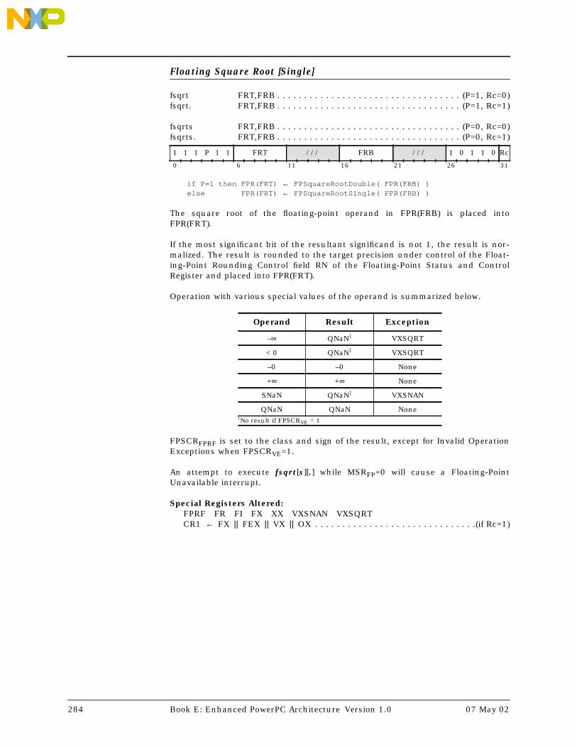
Floating Square Root [Single]
fsqrt FRT,FRB . . . . . . . . . . . . . . . . . . . . . . . . . . . . . . . . . . (P=1, Rc=0)fsqrt. FRT,FRB . . . . . . . . . . . . . . . . . . . . . . . . . . . . . . . . . . (P=1, Rc=1)
fsqrts FRT,FRB . . . . . . . . . . . . . . . . . . . . . . . . . . . . . . . . . . (P=0, Rc=0)fsqrts. FRT,FRB . . . . . . . . . . . . . . . . . . . . . . . . . . . . . . . . . . (P=0, Rc=1)
if P=1 then FPR(FRT) ← FPSquareRootDouble( FPR(FRB) )else FPR(FRT) ← FPSquareRootSingle( FPR(FRB) )
The square root of the floating-point operand in FPR(FRB) is placed intoFPR(FRT).
If the most significant bit of the resultant significand is not 1, the result is nor-malized. The result is rounded to the target precision under control of the Float-ing-Point Rounding Control field RN of the Floating-Point Status and ControlRegister and placed into FPR(FRT).
Operation with various special values of the operand is summarized below.
FPSCRFPRF is set to the class and sign of the result, except for Invalid OperationExceptions when FPSCRVE=1.
An attempt to execute fsqrt[s][.] while MSRFP=0 will cause a Floating-PointUnavailable interrupt.
Special Registers Altered:FPRF FR FI FX XX VXSNAN VXSQRTCR1 ← FX || FEX || VX || OX . . . . . . . . . . . . . . . . . . . . . . . . . . . . . .(if Rc=1)
1 1 1 P 1 1 FRT /// FRB /// 1 0 1 1 0 Rc
0 6 11 16 21 26 31
Operand Result Exception
–∞ QNaN1 VXSQRT
< 0 QNaN1 VXSQRT
–0 –0 None
+∞ +∞ None
SNaN QNaN1 VXSNAN
QNaN QNaN None1No result if FPSCRVE = 1
284 Book E: Enhanced PowerPC Architecture Version 1.0 07 May 02

Floating Subtract [Single]
fsub FRT,FRA,FRB . . . . . . . . . . . . . . . . . . . . . . . . . . . . . . (P=1, Rc=0)fsub. FRT,FRA,FRB . . . . . . . . . . . . . . . . . . . . . . . . . . . . . . (P=1, Rc=1)
fsubs FRT,FRA,FRB . . . . . . . . . . . . . . . . . . . . . . . . . . . . . . (P=0, Rc=0)fsubs. FRT,FRA,FRB . . . . . . . . . . . . . . . . . . . . . . . . . . . . . . (P=0, Rc=1)
if P=1 then FPR(FRT) ← FPR(FRA) - dp FPR(FRB)else FPR(FRT) ← FPR(FRA) - sp FPR(FRB)
The floating-point operand in FPR(FRB) is subtracted from the floating-point oper-and in FPR(FRA).
If the most significant bit of the resultant significand is not 1, the result is nor-malized. The result is rounded to the target precision under control of the Float-ing-Point Rounding Control field RN of the Floating-Point Status and ControlRegister and placed into FPR(FRT).
The execution of the Floating Subtract instruction is identical to that of FloatingAdd, except that the contents of FRB participate in the operation with the sign bit(bit 0) inverted.
FPSCRFPRF is set to the class and sign of the result, except for Invalid OperationExceptions when FPSCRVE=1.
An attempt to execute fsub[s][.] while MSRFP=0 will cause a Floating-PointUnavailable interrupt.
Special Registers Altered:FPRF FR FI FX OX UX XX VXSNAN VXISICR1 ← FX || FEX || VX || OX . . . . . . . . . . . . . . . . . . . . . . . . . . . . . .(if Rc=1)
1 1 1 P 1 1 FRT FRA FRB /// 1 0 1 0 0 Rc
0 6 11 16 21 26 31
07 May 02 Chapter 12 Instruction Set 285

Instruction Cache Block Invalidate
icbi RA,RB . . . . . . . . . . . . . . . . . . . . . . . . . . . . . . (xop=982, X-mode)icbie RA,RB . . . . . . . . . . . . . . . . . . . . . . . . . . . . . (xop=990, XE-mode)
if RA=0 then a ← 640 else a ← GPR(RA)if X-mode then EA ← 320 || (a + GPR(RB)) 32:63if XE-mode then EA ← a + GPR(RB)InvalidateInstructionCacheBlock( EA )
Let the effective address (EA) be calculated as follows:
Addressing Mode EA for RA=0 EA for RA≠0X-mode 320 || GPR(RB)32:63
320 || (GPR(RA)+GPR(RB))32:63XE-mode GPR(RB) GPR(RA)+GPR(RB)
If the block containing the byte addressed by EA is in storage that is MemoryCoherence Required and a block containing the byte addressed by EA is in theinstruction cache of any processors, the block is invalidated in those instructioncaches, so that subsequent references cause the block to be fetched from mainstorage.
If the block containing the byte addressed by EA is in storage that is not MemoryCoherence Required and a block containing the byte addressed by EA is in theinstruction cache of this processor, the block is invalidated in that instructioncache, so that subsequent references cause the block to be fetched from mainstorage.
The function of this instruction is independent of whether the block containingthe byte addressed by EA is in storage that is Write Through Required or CachingInhibited.
This instruction treated as a Load (see Section 6.2.4.4).
This instruction may cause a cache locking exception. See the User’s Manual forthe implementation.
Special Registers Altered:None
0 1 1 1 1 1 /// RA RB 1 1 1 1 0 1 E 1 1 0 /
0 6 11 16 21 31
286 Book E: Enhanced PowerPC Architecture Version 1.0 07 May 02

Instruction Cache Block Touch
icbt CT,RA,RB . . . . . . . . . . . . . . . . . . . . . . . . . . . . . . . (X-mode, E=0)icbte CT,RA,RB . . . . . . . . . . . . . . . . . . . . . . . . . . . . . . (XE-mode, E=1)
if RA=0 then a ← 640 else a ← GPR(RA)if X-mode then EA ← 320 || (a + GPR(RB)) 32:63if XE-mode then EA ← a + GPR(RB)PrefetchInstructionCacheBlock( CT, EA )
Let the effective address (EA) be calculated as follows:
Addressing Mode EA for RA=0 EA for RA≠0X-mode 320 || GPR(RB)32:63
320 || (GPR(RA)+GPR(RB))32:63XE-mode GPR(RB) GPR(RA)+GPR(RB)
If CT=0, this instruction is a hint that performance will probably be improved ifthe block containing the byte addressed by EA is fetched into the instructioncache, because the program will probably soon execute code from the addressedlocation.
An implementation may use other values of CT to enable software to target spe-cific, implementation-dependent portions of its cache hierarchy or structure thatmay better enhance performance. See the User’s Manual for the implementation.
Implementations should perform no operation when CT specifies a value that isnot supported by the implementation.
The hint is ignored if the block is Caching Inhibited.
This instruction treated as a Load (see Section 6.2.4.4), except that an interrupt isnot taken for a translation or protection violation.
Special Registers Altered:None
0 1 1 1 1 1 CT RA RB 0 0 0 0 0 1 E 1 1 0 /
0 6 11 16 21 31
07 May 02 Chapter 12 Instruction Set 287

Instruction Synchronize
isync
The isync instruction provides an ordering function for the effects of all instruc-tions executed by the processor executing the isync instruction. Executing anisync instruction ensures that all instructions preceding the isync instructionhave completed before the isync instruction completes, and that no subsequentinstructions are initiated until after the isync instruction completes. It alsocauses any prefetched instructions to be discarded, with the effect that subse-quent instructions will be fetched and executed in the context established by theinstructions preceding the isync instruction.
The isync instruction may complete before storage accesses associated withinstructions preceding the isync instruction have been performed.
This instruction is context synchronizing (see Section 1.12.1 on page 38).
Special Registers Altered:None
0 1 0 0 1 1 /// 0 0 1 0 0 1 0 1 1 0 /
0 6 21 31
288 Book E: Enhanced PowerPC Architecture Version 1.0 07 May 02

Load Byte and Zero [with Update] [Indexed] [Extended]
lbz RT,D(RA) . . . . . . . . . . . . . . . . . . . . . . . . . . . . . . . . (D-mode, U=0)lbzu RT,D(RA) . . . . . . . . . . . . . . . . . . . . . . . . . . . . . . . . (D-mode, U=1)
lbze RT,DE(RA). . . . . . . . . . . . . . . . . . . . . . . . . . . . . .(DE-mode, U=0)lbzue RT,DE(RA). . . . . . . . . . . . . . . . . . . . . . . . . . . . . .(DE-mode, U=1)
lbzx RT,RA,RB . . . . . . . . . . . . . . . . . . . . . . . . . . . (X-mode, E=0, U=0)lbzux RT,RA,RB . . . . . . . . . . . . . . . . . . . . . . . . . . . (X-mode, E=0, U=1)lbzxe RT,RA,RB . . . . . . . . . . . . . . . . . . . . . . . . . . (XE-mode, E=1, U=0)lbzuxe RT,RA,RB . . . . . . . . . . . . . . . . . . . . . . . . . . (XE-mode, E=1, U=1)
if RA=0 then a ← 640 else a ← GPR(RA)if D-mode then EA ← 320 || (a + EXTS(D)) 32:63if X-mode then EA ← 320 || (a + GPR(RB)) 32:63if DE-mode then EA ← a + EXTS(DE)if XE-mode then EA ← a + GPR(RB)GPR(RT) ← 560 || MEM(EA,1)if U=1 then GPR(RA) ← EA
Let the effective address (EA) be calculated as follows:
• For lbz and lbzu, let EA be 32 0s concatenated with bits 32:63 of the sum ofthe contents of GPR(RA), or 64 0s if RA=0, and the sign-extended value of theD instruction field.
• For lbzx and lbzux, let EA be 32 0s concatenated with bits 32:63 of the sumof the contents of GPR(RA), or 64 0s if RA=0, and the contents of GPR(RB).
• For lbze and lbzue, let EA be the sum of the contents of GPR(RA), or 64 0s ifRA=0, and the sign-extended value of the DE instruction field.
• For lbzxe and lbzuxe, let EA be the sum of the contents of GPR(RA), or 64 0sif RA=0, and the contents of GPR(RB).
The byte in storage addressed by EA is loaded into bits 56:63 of GPR(RT). Bits0:55 of GPR(RT) are set to 0.
If U=1 (‘with update’), EA is placed into GPR(RA).
If U=1 (‘with update’), and RA=0 or RA=RT, the instruction form is invalid.
Special Registers Altered:None
1 0 0 0 1 U RT RA D
0 6 11 16 31
1 1 1 0 1 0 RT RA DE 0 0 0 U
0 6 11 16 28 31
0 1 1 1 1 1 RT RA RB 0 0 0 1 U 1 E 1 1 1 /
0 6 11 16 21 31
07 May 02 Chapter 12 Instruction Set 289

Load Doubleword And Reserve Indexed Extended
ldarxe RT,RA,RB
if RA =0 then EA ← GPR(RB)else EA ← GPR(RA) + GPR(RB)RESERVE← 1RESERVE_ADDR← real_addr(EA)GPR(RT) ← MEM(EA,8)
Let the effective address (EA) be the sum of the contents of GPR(RA), or 64 0s ifRA=0, and the contents of GPR(RB).
The doubleword in storage addressed by EA is loaded into GPR(RT).
This instruction creates a reservation for use by a Store Doubleword Conditionalinstruction. An address computed from the EA is associated with the reservationand replaces any address previously associated with the reservation: the mannerin which the address to be associated with the reservation is computed from theEA is described in Section 6.1.6.2 on page 117.
EA must be a multiple of 8. If it is not, either an Alignment interrupt is invoked orthe results are boundedly undefined.
Special Registers Altered:None
0 1 1 1 1 1 RT RA RB 0 1 1 1 0 1 1 1 1 1 /
0 6 11 16 21 31
290 Book E: Enhanced PowerPC Architecture Version 1.0 07 May 02

Load Doubleword [with Update] [Indexed] Extended
lde RT,DES(RA). . . . . . . . . . . . . . . . . . . . . . . . . . . .(DES-mode, U=0)ldue RT,DES(RA). . . . . . . . . . . . . . . . . . . . . . . . . . . .(DES-mode, U=1)
ldxe RT,RA,RB . . . . . . . . . . . . . . . . . . . . . . . . . . . . . . (XE-mode, U=0)lduxe RT,RA,RB . . . . . . . . . . . . . . . . . . . . . . . . . . . . . . (XE-mode, U=1)
if RA=0 then a ← 640 else a ← GPR(RA)if DES-mode then EA ← a + EXTS(DES ||0b00)if XE-mode then EA ← a + GPR(RB)GPR(RT) ← MEM(EA,8)if U=1 then GPR(RA) ← EA
Let the effective address (EA) be calculated as follows:
• For lde and ldue, let EA be the sum of the contents of GPR(RA), or 64 0s ifRA=0, and the sign-extended value of the DES instruction field concatenatedwith 0b00.
• For ldxe and lduxe, let EA be the sum of the contents of GPR(RA), or 64 0s ifRA=0, and the contents of GPR(RB).
The doubleword in storage addressed by the EA is loaded into GPR(RT).
If U=1 (‘with update’), EA is placed into GPR(RA).
If U=1 (‘with update’), and RA=0 or RA=RT, the instruction form is invalid.
Special Registers Altered:None
1 1 1 1 1 0 RT RA DES 0 0 0 U
0 6 11 16 28 31
0 1 1 1 1 1 RT RA RB 1 1 0 0 U 1 1 1 1 1 /
0 6 11 16 21 31
07 May 02 Chapter 12 Instruction Set 291

Load Floating-Point Double
lfd FRT,D(RA) . . . . . . . . . . . . . . . . . . . . . . . . . . . . . . . (D-mode, U=0)lfdu FRT,D(RA) . . . . . . . . . . . . . . . . . . . . . . . . . . . . . . . (D-mode, U=1)
lfde FRT,DES(RA). . . . . . . . . . . . . . . . . . . . . . . . . . .(DES-mode, U=0)lfdue FRT,DES(RA). . . . . . . . . . . . . . . . . . . . . . . . . . .(DES-mode, U=1)
lfdx FRT,RA,RB . . . . . . . . . . . . . . . . . . . . . . . . . . (X-mode, E=0, U=0)lfdux FRT,RA,RB . . . . . . . . . . . . . . . . . . . . . . . . . . (X-mode, E=0, U=1)lfdxe FRT,RA,RB . . . . . . . . . . . . . . . . . . . . . . . . . (XE-mode, E=1, U=0)lfduxe FRT,RA,RB . . . . . . . . . . . . . . . . . . . . . . . . . (XE-mode, E=1, U=1)
if RA=0 then a ← 640 else a ← GPR(RA)if D-mode then EA ← 320 || (a + EXTS(D)) 32:63if X-mode then EA ← 320 || (a + GPR(RB)) 32:63if DES-mode then EA ← a + EXTS(DES ||0b00)if XE-mode then EA ← a + GPR(RB)FPR(FRT) ← MEM(EA,8)if U=1 then GPR(RA) ← EA
Let the effective address (EA) be calculated as follows:
• For lfd and lfdu, let EA be 32 0s concatenated with bits 32:63 of the sum ofthe contents of GPR(RA), or 64 0s if RA=0, and the sign-extended value of theD instruction field.
• For lfdx and lfdux, let EA be 32 0s concatenated with bits 32:63 of the sumof the contents of GPR(RA), or 64 0s if RA=0, and the contents of GPR(RB).
• For lfde and lfdue, let EA be the sum of the contents of GPR(RA), or 64 0s ifRA=0, and the sign-extended value of the DES instruction fielfd concatenatedwith 0b00.
• For lfdxe and lfduxe, let EA be the sum of the contents of GPR(RA), or 64 0sif RA=0, and the contents of GPR(RB).
The doubleword in storage addressed by EA is placed into FPR(FRT).
If U=1 (‘with update’), EA is placed into register RA.
If U=1 (‘with update’) and RA=0, the instruction form is invalid.
An attempt to execute lfd[u][x][e] while MSRFP=0 will cause a Floating-PointUnavailable interrupt.
Special Registers Altered:None
1 1 0 0 1 U FRT RA D
0 6 11 16 31
1 1 1 1 1 0 FRT RA DES 0 1 1 U
0 6 11 16 28 31
0 1 1 1 1 1 FRT RA RB 1 0 0 1 U 1 E 1 1 1 /
0 6 11 16 21 31
292 Book E: Enhanced PowerPC Architecture Version 1.0 07 May 02

Load Floating-Point Single
lfs FRT,D(RA) . . . . . . . . . . . . . . . . . . . . . . . . . . . . . . . (D-mode, U=0)lfsu FRT,D(RA) . . . . . . . . . . . . . . . . . . . . . . . . . . . . . . . (D-mode, U=1)
lfse FRT,DES(RA). . . . . . . . . . . . . . . . . . . . . . . . . . .(DES-mode, U=0)lfsue FRT,DES(RA). . . . . . . . . . . . . . . . . . . . . . . . . . .(DES-mode, U=1)
lfsx FRT,RA,RB . . . . . . . . . . . . . . . . . . . . . . . . . . (X-mode, E=0, U=0)lfsux FRT,RA,RB . . . . . . . . . . . . . . . . . . . . . . . . . . (X-mode, E=0, U=1)lfsxe FRT,RA,RB . . . . . . . . . . . . . . . . . . . . . . . . . (XE-mode, E=1, U=0)lfsuxe FRT,RA,RB . . . . . . . . . . . . . . . . . . . . . . . . . (XE-mode, E=1, U=1)
if RA=0 then a ← 640 else a ← GPR(RA)if D-mode then EA ← 320 || (a + EXTS(D)) 32:63if X-mode then EA ← 320 || (a + GPR(RB)) 32:63if DES-mode then EA ← a + EXTS(DES ||0b00)if XE-mode then EA ← a + GPR(RB)FPR(FRT) ← DOUBLE(MEM(EA,4))if U=1 then GPR(RA) ← EA
Let the effective address (EA) be calculated as follows:
• For lfs and lfsu, let EA be 32 0s concatenated with bits 32:63 of the sum ofthe contents of GPR(RA), or 64 0s if RA=0, and the sign-extended value of theD instruction field.
• For lfsx and lfsux, let EA be 32 0s concatenated with bits 32:63 of the sum ofthe contents of GPR(RA), or 64 0s if RA=0, and the contents of GPR(RB).
• For lfse and lfsue, let EA be the sum of the contents of GPR(RA), or 64 0s ifRA=0, and the sign-extended value of the DES instruction fielfs concatenatedwith 0b00.
• For lfsxe and lfsuxe, let EA be the sum of the contents of GPR(RA), or 64 0s ifRA=0, and the contents of GPR(RB).
The word in storage addressed by EA is interpreted as a floating-point single-pre-cision operand. This word is converted to floating-point double format (see page98) and placed into FPR(FRT).
If U=1 (‘with update’), EA is placed into register RA.
If U=1 (‘with update’) and RA=0, the instruction form is invalid.
An attempt to execute lfs[u][x][e] while MSRFP=0 will cause a Floating-PointUnavailable interrupt.
Special Registers Altered:None
1 1 0 0 0 U FRT RA D
0 6 11 16 31
1 1 1 1 1 0 FRT RA DES 0 1 0 U
0 6 11 16 28 31
0 1 1 1 1 1 FRT RA RB 1 0 0 0 U 1 E 1 1 1 /
0 6 11 16 21 31
07 May 02 Chapter 12 Instruction Set 293

Load Halfword Algebraic [with Update] [Indexed] [Extended]
lha RT,D(RA) . . . . . . . . . . . . . . . . . . . . . . . . . . . . . . . . (D-mode, U=0)lhau RT,D(RA) . . . . . . . . . . . . . . . . . . . . . . . . . . . . . . . . (D-mode, U=1)
lhae RT,DE(RA). . . . . . . . . . . . . . . . . . . . . . . . . . . . . .(DE-mode, U=0)lhaue RT,DE(RA). . . . . . . . . . . . . . . . . . . . . . . . . . . . . .(DE-mode, U=1)
lhax RT,RA,RB . . . . . . . . . . . . . . . . . . . . . . . . . . . (X-mode, E=0, U=0)lhaux RT,RA,RB . . . . . . . . . . . . . . . . . . . . . . . . . . . (X-mode, E=0, U=1)lhaxe RT,RA,RB . . . . . . . . . . . . . . . . . . . . . . . . . . (XE-mode, E=1, U=0)lhauxe RT,RA,RB . . . . . . . . . . . . . . . . . . . . . . . . . . (XE-mode, E=1, U=1)
if RA=0 then a ← 640 else a ← GPR(RA)if D-mode then EA ← 320 || (a + EXTS(D)) 32:63if X-mode then EA ← 320 || (a + GPR(RB)) 32:63if DE-mode then EA ← a + EXTS(DE)if XE-mode then EA ← a + GPR(RB)GPR(RT) ← 320 || EXTS(MEM(EA,2)) 32:63if U=1 then GPR(RA) ← EA
Let the effective address (EA) be calculated as follows:
• For lha and lhau, let EA be 32 0s concatenated with bits 32:63 of the sum ofthe contents of GPR(RA), or 64 0s if RA=0, and the sign-extended value of theD instruction field.
• For lhax and lhaux, let EA be 32 0s concatenated with bits 32:63 of the sumof the contents of GPR(RA), or 64 0s if RA=0, and the contents of GPR(RB).
• For lhae and lhaue, let EA be the sum of the contents of GPR(RA), or 64 0s ifRA=0, and the sign-extended value of the DE instruction field.
• For lhaxe and lhauxe, let EA be the sum of the contents of GPR(RA), or 64 0sif RA=0, and the contents of GPR(RB).
The halfword in storage addressed by EA is loaded into bits 48:63 of GPR(RT). Bits32:47 of GPR(RT) are filled with a copy of bit 0 of the loaded halfword. Bits 0:31 ofGPR(RT) are set to 0.
If U=1 (‘with update’), EA is placed into GPR(RA).
If U=1 (‘with update’), and RA=0 or RA=RT, the instruction form is invalid.
Special Registers Altered:None
1 0 1 0 1 U RT RA D
0 6 11 16 31
1 1 1 0 1 0 RT RA DE 0 1 0 U
0 6 11 16 28 31
0 1 1 1 1 1 RT RA RB 0 1 0 1 U 1 E 1 1 1 /
0 6 11 16 21 31
294 Book E: Enhanced PowerPC Architecture Version 1.0 07 May 02

Load Halfword Byte-Reverse Indexed [Extended]
lhbrx RT,RA,RB . . . . . . . . . . . . . . . . . . . . . . . . . . . . . . . (X-mode, E=0)lhbrxe RT,RA,RB . . . . . . . . . . . . . . . . . . . . . . . . . . . . . . (XE-mode, E=1)
if RA=0 then a ← 640 else a ← GPR(RA)if X-mode then EA ← 320 || (a + GPR(RB)) 32:63if XE-mode then EA ← a + GPR(RB)data 0:15 ← MEM(EA,2)GPR(RT) ← 480 || data 8:15 || data 0:7
Let the effective address (EA) be calculated as follows:
• For lhbrx, let EA be 32 0s concatenated with bits 32:63 of the sum of the con-tents of GPR(RA), or 64 0s if RA=0, and the contents of GPR(RB).
• For lhbrxe, let EA be the sum of the contents of GPR(RA), or 64 0s if RA=0,and the contents of GPR(RB).
Bits 0:7 of the halfword in storage addressed by EA are loaded into bits 56:63 ofGPR(RT). Bits 8:15 of the halfword in storage addressed by EA are loaded intobits 48:55 of GPR(RT). Bits 0:47 of GPR(RT) are set to 0.
Special Registers Altered:None
0 1 1 1 1 1 RT RA RB 1 1 0 0 0 1 E 1 1 0 /
0 6 11 16 21 31
Programming NoteWhen EA references Big-Endian storage, these instructions have the effect of loadingdata in Little-Endian byte order. Likewise, when EA references Little-Endian storage,these instructions have the effect of loading data in Big-Endian byte order.
Programming NoteIn some implementations, the Load Halfword Byte-Reverse Indexed instructions mayhave greater latency than other Load instructions.
07 May 02 Chapter 12 Instruction Set 295

Load Halfword and Zero [with Update] [Indexed] [Extended]
lhz RT,D(RA) . . . . . . . . . . . . . . . . . . . . . . . . . . . . . . . . (D-mode, U=0)lhzu RT,D(RA) . . . . . . . . . . . . . . . . . . . . . . . . . . . . . . . . (D-mode, U=1)
lhze RT,DE(RA). . . . . . . . . . . . . . . . . . . . . . . . . . . . . .(DE-mode, U=0)lhzue RT,DE(RA). . . . . . . . . . . . . . . . . . . . . . . . . . . . . .(DE-mode, U=1)
lhzx RT,RA,RB . . . . . . . . . . . . . . . . . . . . . . . . . . . (X-mode, E=0, U=0)lhzux RT,RA,RB . . . . . . . . . . . . . . . . . . . . . . . . . . . (X-mode, E=0, U=1)lhzxe RT,RA,RB . . . . . . . . . . . . . . . . . . . . . . . . . . (XE-mode, E=1, U=0)lhzuxe RT,RA,RB . . . . . . . . . . . . . . . . . . . . . . . . . . (XE-mode, E=1, U=1)
if RA=0 then a ← 640 else a ← GPR(RA)if D-mode then EA ← 320 || (a + EXTS(D)) 32:63if X-mode then EA ← 320 || (a + GPR(RB)) 32:63if DE-mode then EA ← a + EXTS(DE)if XE-mode then EA ← a + GPR(RB)GPR(RT) ← 480 || MEM(EA,2)if U=1 then GPR(RA) ← EA
Let the effective address (EA) be calculated as follows:
• For lhz and lhzu, let EA be 32 0s concatenated with bits 32:63 of the sum ofthe contents of GPR(RA), or 64 0s if RA=0, and the sign-extended value of theD instruction field.
• For lhzx and lhzux, let EA be 32 0s concatenated with bits 32:63 of the sumof the contents of GPR(RA), or 64 0s if RA=0, and the contents of GPR(RB).
• For lhze and lhzue, let EA be the sum of the contents of GPR(RA), or 64 0s ifRA=0, and the sign-extended value of the DE instruction field.
• For lhzxe and lhzuxe, let EA be the sum of the contents of GPR(RA), or 64 0sif RA=0, and the contents of GPR(RB).
The halfword in storage addressed by EA is loaded into bits 48:63 of GPR(RT). Bits0:47 of GPR(RT) are set to 0.
If U=1 (‘with update’), EA is placed into GPR(RA).
If U=1 (‘with update’), and RA=0 or RA=RT, the instruction form is invalid.
Special Registers Altered:None
1 0 1 0 0 U RT RA D
0 6 11 16 31
1 1 1 0 1 0 RT RA DE 0 0 1 U
0 6 11 16 28 31
0 1 1 1 1 1 RT RA RB 0 1 0 0 U 1 E 1 1 1 /
0 6 11 16 21 31
296 Book E: Enhanced PowerPC Architecture Version 1.0 07 May 02

Load Multiple Word
lmw RT,D(RA)
if RA =0 then EA ← 320 || EXTS(D) 32:63else EA ← 320 || (GPR(RA)+EXTS(D)) 32:63r ← RTdo while r ≤ 31
GPR(r) ← 320 || MEM(EA,4)r ← r + 1EA ← 320 || (EA+4) 32:63
Let the effective address (EA) be 32 0s concatenated with bits 32:63 of the sum ofthe contents of GPR(RA), or 64 0s if RA=0, and the sign-extended value of the Dinstruction field.
Let n=(32-RT). n consecutive words in storage starting at address EA are loadedinto bits 32:63 of registers GPR(RT) through GPR(31). Bits 0:31 of these GPRs areset to zero.
EA must be a multiple of 4. If it is not, either an Alignment interrupt is invoked orthe results are boundedly undefined. If RA is in the range of registers to be loaded,including the case in which RA=0, the instruction form is invalid.
Special Registers Altered:None
1 0 1 1 1 0 RT RA D
0 6 11 16 31
Engineering NoteCausing an Alignment interrupt if an attempt is made to execute a Load Multipleinstruction having an incorrectly aligned effective address facilitates the debugging ofsoftware.
Architecture NoteExtended addressing modes are not defined for Load Multiple. Doubleword forms of LoadMultiple are not defined.
07 May 02 Chapter 12 Instruction Set 297

Load String Word (Immediate | Indexed)
lswi RT,RA,NB
lswx RT,RA,RB
if RA=0 then a ← 640 else a ← GPR(RA)if ‘lswi’ then EA ← 320 || a 32:63if ‘lswx’ then EA ← 320 || (a + GPR(RB)) 32:63if ‘lswi’ & NB=0 then n ← 32if ‘lswi’ & NB ≠0 then n ← NBif ‘lswx’ then n ← XER57:63r ← RT – 1i ← 32GPR(RT) ← undefineddo while n > 0
if i = 32 thenr ← r + 1 (mod 32)GPR(r) ← 0
GPR(r) i:i+7 ← MEM(EA,1)i ← i + 8if i = 64 then i ← 32EA ← 320 || (EA+1) 32:63n ← n – 1
Let the effective address (EA) be calculated as follows:
• For lswi, let EA be 32 0s concatenated with the contents of bits 32:63 ofGPR(RA), or 32 0s if RA=0.
• For lswx, let EA be 32 0s concatenated with bits 32:63 of the sum of the con-tents of GPR(RA), or 64 0s if RA=0, and the contents of GPR(RB).
If lswi then n=NB if NB≠0, n=32 if NB=0. If lswx then n=XER57:63. n is the num-ber of bytes to load. Let nr=CEIL(n÷4): nr is the number of registers to receivedata.
If n>0, n consecutive bytes in storage starting at address EA are loaded into regis-ters GPR(RT) through GPR(RT+nr–1). Data are loaded into the low-order fourbytes of each GPR; the high-order four bytes are set to 0.
Bytes are loaded left to right in each register. The sequence of registers wrapsaround to GPR(0) if required. If the low-order four bytes of GPR(RT+nr–1) are onlypartially filled, the unfilled low-order byte(s) of that register are set to 0.
If lswx and n=0, the contents of GPR(RT) are undefined.
If RA, or RB for lswx, is in the range of registers to be loaded, including the casein which RA=0, either an Illegal Instruction type Program interrupt is invoked orthe results are boundedly undefined. If RT=RA, or RT=RB for lswx, the instruc-tion form is invalid.
Special Registers Altered:None
0 1 1 1 1 1 RT RA NB 1 0 0 1 0 1 0 1 0 1 /
0 6 11 16 21 31
0 1 1 1 1 1 RT RA RB 1 0 0 0 0 1 0 1 0 1 /
0 6 11 16 21 31
298 Book E: Enhanced PowerPC Architecture Version 1.0 07 May 02

Programming NoteThe Load String Word instructions, in combination with the Store String Word instruc-tions allow movement of data from storage to registers or from registers to storagewithout concern for alignment. These instructions can be used for a short move betweenarbitrary storage locations or to initiate a long move between unaligned storage fields.
Architecture NoteExtended addressing modes are not defined for the Load String Word instructions. Dou-bleword forms of the Load String Word instructions are not defined.
07 May 02 Chapter 12 Instruction Set 299

Load Word And Reserve Indexed [Extended]
lwarx RT,RA,RB . . . . . . . . . . . . . . . . . . . . . . . . . . . . . . . . . . . (X-mode)
lwarxe RT,RA,RB . . . . . . . . . . . . . . . . . . . . . . . . . . . . . . . . . . (XE-mode)
if RA=0 then a ← 640 else a ← GPR(RA)if X-mode then EA ← 320 || (a + GPR(RB)) 32:63if XE-mode then EA ← a + GPR(RB)RESERVE← 1RESERVE_ADDR← real_addr(EA)GPR(RT) ← 320 || MEM(EA,4)
Let the effective address (EA) be calculated as follows:
• For lwarx, let EA be 32 0s concatenated with bits 32:63 of the sum of thecontents of GPR(RA), or 64 0s if RA=0, and the contents of GPR(RB).
• For lwarxe, let EA be the sum of the contents of GPR(RA), or 64 0s if RA=0,and the contents of GPR(RB).
The word in storage addressed by EA is loaded into GPR(RT)32:63. GPR(RT)0:31 areset to 0.
This instruction creates a reservation for use by a Store Word Conditional instruc-tion. An address computed from the EA is associated with the reservation andreplaces any address previously associated with the reservation: the manner inwhich the address to be associated with the reservation is computed from the EAis described in Section 6.1.6.2 on page 117.
EA must be a multiple of 4. If it is not, either an Alignment interrupt is invoked orthe results are boundedly undefined.
Special Registers Altered:None
0 1 1 1 1 1 RT RA RB 0 0 0 0 0 1 0 1 0 0 /
0 6 11 16 21 31
0 1 1 1 1 1 RT RA RB 0 0 0 1 1 1 1 1 1 0 /
0 6 11 16 21 31
Programming Notelwarx, lwarxe, and ldarxe, in combination with stwcx., stwcxe., and stdcxe., permitthe programmer to write a sequence of instructions that appear to perform an atomicupdate operation on a storage location. This operation depends upon a single reserva-tion resource in each processor. At most one reservation exists on any given processor:there are not separate reservations for words and for doublewords.
Programming NoteBecause lwarx, lwarxe, and ldarxe have implementation dependencies (e.g., the gran-ularity at which reservations are managed), they must be used with care. The operatingsystem should provide system library programs that use these instructions to imple-ment the high-level synchronization functions (Test and Set, Compare and Swap, etc.)needed by application programs. Application programs should use these library pro-grams, rather than use lwarx, lwarxe, and ldarxe directly.
Architecture Notelwarx, lwarxe, and ldarxe require the EA to be aligned. Software should not attempt toemulate an unaligned lwarx, lwarxe, or ldarxe, because there is no correct way todefine the address associated with the reservation.
300 Book E: Enhanced PowerPC Architecture Version 1.0 07 May 02

Engineering NoteCausing an Alignment interrupt to be invoked if an attempt is made to execute a lwarx,lwarxe, or ldarxe having an incorrectly aligned effective address facilitates the debug-ging of software by signalling the exception when and where the exception occurs.
Programming NoteThe granularity with which reservations are managed is implementation-dependent.Therefore the storage to be accessed by lwarx, lwarxe, or ldarxe should be allocated bya system library program. Additional information can be found in Section 6.1.6.2 onpage 117.
07 May 02 Chapter 12 Instruction Set 301

Load Word Byte-Reverse Indexed [Extended]
lwbrx RT,RA,RB . . . . . . . . . . . . . . . . . . . . . . . . . . . . . . . (X-mode, E=0)lwbrxe RT,RA,RB . . . . . . . . . . . . . . . . . . . . . . . . . . . . . . (XE-mode, E=1)
if RA=0 then a ← 640 else a ← GPR(RA)if X-mode then EA ← 320 || (a + GPR(RB)) 32:63if XE-mode then EA ← a + GPR(RB)data 0:31 ← MEM(EA,4)GPR(RT) ← 320 || data 24:31 || data 16:23 || data 8:15 || data 0:7
Let the effective address (EA) be calculated as follows:
• For lwbrx, let EA be 32 0s concatenated with bits 32:63 of the sum of thecontents of GPR(RA), or 64 0s if RA=0, and the contents of GPR(RB).
• For lwbrxe, let EA be the sum of the contents of GPR(RA), or 64 0s if RA=0,and the contents of GPR(RB).
Bits 0:7 of the word in storage addressed by EA are loaded into bits 56:63 ofGPR(RT). Bits 8:15 of the word in storage addressed by EA are loaded into bits48:55 of GPR(RT). Bits 16:23 of the word in storage addressed by EA are loadedinto bits 40:47 of GPR(RT). Bits 24:31 of the word in storage addressed by EA areloaded into bits 32:39 of GPR(RT). Bits 0:31 of GPR(RT) are set to 0.
Special Registers Altered:None
0 1 1 1 1 1 RT RA RB 1 0 0 0 0 1 E 1 1 0 /
0 6 11 16 21 31
Programming NoteWhen EA references Big-Endian storage, these instructions have the effect of loadingdata in Little-Endian byte order. Likewise, when EA references Little-Endian storage,these instructions have the effect of loading data in Big-Endian byte order.
Programming NoteIn some implementations, the Load Word Byte-Reverse instructions may have greaterlatency than other Load instructions.
302 Book E: Enhanced PowerPC Architecture Version 1.0 07 May 02

Load Word and Zero [with Update] [Indexed] [Extended]
lwz RT,D(RA) . . . . . . . . . . . . . . . . . . . . . . . . . . . . . . . . (D-mode, U=0)lwzu RT,D(RA) . . . . . . . . . . . . . . . . . . . . . . . . . . . . . . . . (D-mode, U=1)
lwze RT,DE(RA). . . . . . . . . . . . . . . . . . . . . . . . . . . . . .(DE-mode, U=0)lwzue RT,DE(RA). . . . . . . . . . . . . . . . . . . . . . . . . . . . . .(DE-mode, U=1)
lwzx RT,RA,RB . . . . . . . . . . . . . . . . . . . . . . . . . . . (X-mode, E=0, U=0)lwzux RT,RA,RB . . . . . . . . . . . . . . . . . . . . . . . . . . . (X-mode, E=0, U=1)lwzxe RT,RA,RB . . . . . . . . . . . . . . . . . . . . . . . . . . (XE-mode, E=1, U=0)lwzuxe RT,RA,RB . . . . . . . . . . . . . . . . . . . . . . . . . . (XE-mode, E=1, U=1)
if RA=0 then a ← 640 else a ← GPR(RA)if D-mode then EA ← 320 || (a + EXTS(D)) 32:63if X-mode then EA ← 320 || (a + GPR(RB)) 32:63if DE-mode then EA ← a + EXTS(DE)if XE-mode then EA ← a + GPR(RB)GPR(RT) ← 320 || MEM(EA,4)if U=1 then GPR(RA) ← EA
Let the effective address (EA) be calculated as follows:
• For lwz and lwzu, let EA be 32 0s concatenated with bits 32:63 of the sum ofthe contents of GPR(RA), or 64 0s if RA=0, and the sign-extended value of theD instruction field.
• For lwzx and lwzux, let EA be 32 0s concatenated with bits 32:63 of the sumof the contents of GPR(RA), or 64 0s if RA=0, and the contents of GPR(RB).
• For lwze and lwzue, let EA be the sum of the contents of GPR(RA), or 64 0s ifRA=0, and the sign-extended value of the DE instruction field.
• For lwzxe and lwzuxe, let EA be the sum of the contents of GPR(RA), or 64 0sif RA=0, and the contents of GPR(RB).
The word in storage addressed by the EA is loaded into bits 32:63 of GPR(RT). Bits0:31 of GPR(RT) are set to 0.
If U=1 (‘with update’), EA is placed into GPR(RA).
If U=1 (‘with update’), and RA=0 or RA=RT, the instruction form is invalid.
Special Registers Altered:None
1 0 0 0 0 U RT RA D
0 6 11 16 31
1 1 1 0 1 0 RT RA DE 0 1 1 U
0 6 11 16 28 31
0 1 1 1 1 1 RT RA RB 0 0 0 0 U 1 E 1 1 1 /
0 6 11 16 21 31
07 May 02 Chapter 12 Instruction Set 303

Memory Barrier
mbar MO
When MO=0, the mbar instruction provides a storage ordering function for allstorage access instructions executed by the processor executing the mbarinstruction. Executing an mbar instruction ensures that all data storage accessescaused by instructions preceding the mbar instruction have completed before anydata storage accesses caused by any instructions after the mbar instruction. Thisorder is seen by all mechanisms.
When MO≠0, an implementation may support the mbar instruction ordering aparticular subset of storage accesses. An implementation may also support multi-ple, non-zero values of MO that each specify a different subset of storage accessesthat are ordered by the mbar instruction. Which subsets of storage accesses thatare ordered and which values of MO that specify these subsets is implementation-dependent. See the User’s Manual for the implementation.
Special Registers Altered:None
0 1 1 1 1 1 MO / / / 1 1 0 1 0 1 0 1 1 0 /
0 6 11 21 31
Programming Notembar is provided to implement a pipelined storage barrier. The following sequence illus-trates one use of mbar in supporting shared data, ensuring the action is completedprior to releasing the lock.
P1 P2lock . . .read & write . . .mbar . . .free lock . . .. . . lock. . . read & write. . . mbar. . . free lock
See also Appendix D on page 397.
304 Book E: Enhanced PowerPC Architecture Version 1.0 07 May 02

Move Condition Register Field
mcrf BF,BFA
CR4xBF+32:4xBF+35 ← CR4xBFA+32:4xBFA+35
The contents of field BFA (bits 4×BFA+32:4×BFA+35) of the Condition Register arecopied to field BF (bits 4×BF+32:4×BF+35) of the Condition Register.
Special Registers Altered:CR
0 1 0 0 1 1 BF // BFA /// 0 0 0 0 0 0 0 0 0 0 /
0 6 9 11 14 21 31
07 May 02 Chapter 12 Instruction Set 305

Move to Condition Register from Floating-Point Status and ControlRegister
mcrfs BF,BFA
CRBF×4:BF ×4+3 ← FPSCRBFA×4:BFA ×4+3FPSCRBFA×4:BFA ×4+3 ← 0b0000
The contents of Floating-Point Status and Control Register field BFA are copied toCondition Register field BF. All exception bits copied are set to 0 in the Floating-Point Status and Control Register. If the FX bit is copied, it is set to 0 in the Float-ing-Point Status and Control Register.
An attempt to execute mcrfs while MSRFP=0 will cause a Floating-Point Unavail-able interrupt.
Special Registers Altered:CR field BFFX OX . . . . . . . . . . . . . . . . . . . . . . . . . . . . . . . . . . . . . . . . . . . . . . (if BFA=0)UX ZX XX VXSNAN. . . . . . . . . . . . . . . . . . . . . . . . . . . . . . . . . . (if BFA=1)VXISI VXIDI VXZDZ VXIMZ. . . . . . . . . . . . . . . . . . . . . . . . . . . . (if BFA=2)VXVC . . . . . . . . . . . . . . . . . . . . . . . . . . . . . . . . . . . . . . . . . . . . . . . (if BFA=3)VXSOFT VXSQRT VXCVI. . . . . . . . . . . . . . . . . . . . . . . . . . . . . . . (if BFA=5)
Move to Condition Register from Integer Exception Register
mcrxr BF
CR4×BF+32:4 ×BF+35 ← XER32:35XER32:35 ← 0b0000
The contents of bits 32:35 of the Integer Exception Register are copied to Condi-tion Register field BF. Bits 32:35 of the Integer Exception Register are set to zero.
Special Registers Altered:CR XER32:35
Move to Condition Register from Integer Exception Register 64
mcrxr64 BF
CR4×BF+32:4 ×BF+35 ← XER0:3XER0:3 ← 0b0000
The contents of bits 0:3 of the Integer Exception Register are copied to ConditionRegister field BF. Bits 0:3 of the Integer Exception Register are set to zero.
Special Registers Altered:CR XER0:3
1 1 1 1 1 1 BF // BFA /// 0 0 0 1 0 0 0 0 0 0 /
0 6 9 11 14 21 31
0 1 1 1 1 1 BF /// 1 0 0 0 0 0 0 0 0 0 /
0 6 9 21 31
0 1 1 1 1 1 BF /// 1 0 0 0 1 0 0 0 0 0 /
0 6 9 21 31
306 Book E: Enhanced PowerPC Architecture Version 1.0 07 May 02

Move From APID Indirect
mfapidi RT,RA
GPR(RT) ← implementation-dependent value based on GPR(RA)
The contents of GPR(RA) are provided to any auxiliary processing extensions thatmay be present. A value, that is implementation-dependent and extension-depen-dent, is placed in GPR(RT).
Special Registers Altered:None
Move From Condition Register
mfcr RT
GPR(RT) ← 320 || CR
The contents of the Condition Register are placed into bits 32:63 of GPR(RT). Bits0:31 of GPR(RT) are set to 0.
Special Registers Altered:None
Move From Device Control Register
mfdcr RT,DCRN
DCRN ← dcrn 0:4 || dcrn 5:9GPR(RT) ← DCREG(DCRN)
Let DCRN denote a Device Control Register (see User’s Manual for a list of theDevice Control Registers supported by the implemention).
The contents of the designated Device Control Register are placed into GPR(RT).For 32-bit Device Control Registers, the contents of the Device Control Registerare placed into bits 32:63 of GPR(RT). Bits 0:31 of GPR(RT) are set to 0.
Execution of this instruction is privileged and restricted to supervisor mode only.
Special Registers Altered:None
0 1 1 1 1 1 RT RA /// 0 1 0 0 0 1 0 0 1 1 /
0 6 11 16 21 31
Programming NoteThis instruction is provided as a mechanism for software to query the presence and con-figuration of one or more auxiliary processing extensions. See User’s Manual for theimplementation for details on the behavior of this instruction.
0 1 1 1 1 1 RT /// 0 0 0 0 0 1 0 0 1 1 /
0 6 11 21 31
0 1 1 1 1 1 RT dcrn5:9 dcrn0:4 0 1 0 1 0 0 0 0 1 1 /
0 6 11 16 21 31
07 May 02 Chapter 12 Instruction Set 307

Move From Floating-Point Status and Control Register
mffs FRT. . . . . . . . . . . . . . . . . . . . . . . . . . . . . . . . . . . . . . . . . . (Rc=0)mffs. FRT. . . . . . . . . . . . . . . . . . . . . . . . . . . . . . . . . . . . . . . . . . (Rc=1)
FPR(FRT) ← FPSCR
The contents of the Floating-Point Status and Control Register are placed into bits32:63 of FPR(FRT). Bits 0:31 of FPR(FRT) are undefined.
An attempt to execute mffs[.] while MSRFP=0 will cause a Floating-Point Unavail-able interrupt.
Special Registers Altered:CR1 ← FX || FEX || VX || OX . . . . . . . . . . . . . . . . . . . . . . . . . . . . . .(if Rc=1)
Move From Machine State Register
mfmsr RT
GPR(RT) ← 320 || MSR
The contents of the MSR are placed into bits 32:63 of GPR(RT). Bits 0:31 ofGPR(RT) are set to 0.
Execution of this instruction is privileged and restricted to supervisor mode only.
Special Registers Altered:None
1 1 1 1 1 1 FRT /// 1 0 0 1 0 0 0 1 1 1 Rc
0 6 11 16 21 31
0 1 1 1 1 1 RT /// 0 0 0 1 0 1 0 0 1 1 /
0 6 11 21 31
308 Book E: Enhanced PowerPC Architecture Version 1.0 07 May 02

Move From Special Purpose Register
mfspr RT,SPRN
SPRN ← sprn 0:4 || sprn 5:9GPR(RT) ← SPREG(SPRN)
Let SPRN denote a Special Purpose Register (see Section B.1 for a list of SpecialPurpose Registers defined by Book E, Section B.3 for a list of SPRN valuesreserved by Book E, Section B.4 for a list of SPRN values allocated by Book E, andSection B.2 for a list of Special Purpose Registers preserved by Book E).
The contents of the designated Special Purpose Register are placed into GPR(RT).For 32-bit Special Purpose Registers, the contents of the Special Purpose Registerare placed into bits 32:63 of GPR(RT). Bits 0:31 of GPR(RT) are set to 0.
Execution of this instruction specifying a defined and privileged Special PurposeRegister (SPRN5=1) when MSRPR=1 will result in a Privileged Instruction exceptiontype Program interrupt.
Special Registers Altered:None
0 1 1 1 1 1 RT sprn5:9 sprn0:4 0 1 0 1 0 1 0 0 1 1 /
0 6 11 16 21 31
SPRN5 MSRPRSPRNClass Result
0 1 defined if not implemented: Illegal Instruction exceptionif implemented: as defined in Book E
0 1 allocated if not implemented: Illegal Instruction exceptionif implemented: as defined in User’s Manual
0 1 preserved if not implemented: Illegal Instruction exceptionif implemented: as defined in PowerPC Architecture
0 1 reserved Illegal Instruction exception
1 1 — Privileged exception
— 0 defined if not implemented: boundedly undefinedif implemented: as defined in Book E
— 0 allocated if not implemented: boundedly undefinedif implemented: as defined in User’s Manual
— 0 preserved if not implemented: boundedly undefinedif implemented: as defined in PowerPC Architecture
— 0 reserved boundedly undefined
07 May 02 Chapter 12 Instruction Set 309
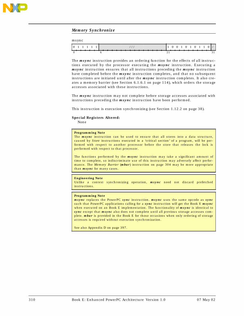
Memory Synchronize
msync
The msync instruction provides an ordering function for the effects of all instruc-tions executed by the processor executing the msync instruction. Executing amsync instruction ensures that all instructions preceding the msync instructionhave completed before the msync instruction completes, and that no subsequentinstructions are initiated until after the msync instruction completes. It also cre-ates a memory barrier (see Section 6.1.6.1 on page 114), which orders the storageaccesses associated with these instructions.
The msync instruction may not complete before storage accesses associated withinstructions preceding the msync instruction have been performed.
This instruction is execution synchronizing (see Section 1.12.2 on page 38).
Special Registers Altered:None
0 1 1 1 1 1 /// 1 0 0 1 0 1 0 1 1 0 /
0 6 21 31
Programming NoteThe msync instruction can be used to ensure that all stores into a data structure,caused by Store instructions executed in a ‘critical section’ of a program, will be per-formed with respect to another processor before the store that releases the lock isperformed with respect to that processor.
The functions performed by the msync instruction may take a significant amount oftime to complete, so indiscriminate use of this instruction may adversely affect perfor-mance. The Memory Barrier (mbar) instruction on page 304 may be more appropriatethan msync for many cases.
Engineering NoteUnlike a context synchronizing operation, msync need not discard prefetchedinstructions.
Programming Notemsync replaces the PowerPC sync instruction. msync uses the same opcode as syncsuch that PowerPC applications calling for a sync instruction will get the Book E msyncwhen executed on an Book E implementation. The functionality of msync is identical tosync except that msync also does not complete until all previous storage accesses com-plete. mbar is provided in the Book E for those occasions when only ordering of storageaccesses is required without execution synchronization.
See also Appendix D on page 397.
310 Book E: Enhanced PowerPC Architecture Version 1.0 07 May 02

Move To Condition Register Fields
mtcrf FXM,RS
i ← 0do while i < 8
if FXM i =1 then CR 4×i+32:4 ×i+35 ← GPR(RS) 4×i+32:4 ×i+35i ← i+1
The contents of bits 32:63 of GPR(RS) are placed into the Condition Registerunder control of the field mask specified by FXM. The field mask identifies the 4-bit fields affected. Let i be an integer in the range 0-7. If FXMi = 1 then CR field i(CR bits 4×i+32 through 4×i+35) is set to the contents of the corresponding field ofbits 32:63 of GPR(RS).
Special Registers Altered:CR fields selected by mask
Move To Device Control Register
mtdcr DCRN,RS
DCRN ← dcrn 0:4 || dcrn 5:9DCREG(DCRN)← GPR(RS)
Let DCRN denote a Device Control Register (see User’s Manual for a list of theDevice Control Registers supported by the implemention).
The contents of GPR(RS) are placed into the designated Device Control Register.For 32-bit Device Control Registers, the contents of bits 32:63 of GPR(RS) areplaced into the Device Control Register.
Execution of this instruction is privileged and restricted to supervisor mode only.
Special Registers Altered:See the User’s Manual for the implementation
0 1 1 1 1 1 RS / FXM / 0 0 1 0 0 1 0 0 0 0 /
0 6 11 12 20 21 31
0 1 1 1 1 1 RS dcrn5:9 dcrn0:4 0 1 1 1 0 0 0 0 1 1 /
0 6 11 16 21 31
07 May 02 Chapter 12 Instruction Set 311

Move To Floating-Point Status and Control Register Bit 0
mtfsb0 BT. . . . . . . . . . . . . . . . . . . . . . . . . . . . . . . . . . . . . . . . . . . (Rc=0)mtfsb0. BT. . . . . . . . . . . . . . . . . . . . . . . . . . . . . . . . . . . . . . . . . . . (Rc=1)
FPSCRBT+32 ← 0b0
Bit BT+32 of the Floating-Point Status and Control Register is set to 0.
An attempt to execute mtfsb0[.] while MSRFP=0 will cause a Floating-PointUnavailable interrupt.
Special Registers Altered:FPSCR bit BTCR1 ← FX || FEX || VX || OX . . . . . . . . . . . . . . . . . . . . . . . . . . . . . .(if Rc=1)
Move To Floating-Point Status and Control Register Bit 1
mtfsb1 BT. . . . . . . . . . . . . . . . . . . . . . . . . . . . . . . . . . . . . . . . . . . (Rc=0)mtfsb1. BT. . . . . . . . . . . . . . . . . . . . . . . . . . . . . . . . . . . . . . . . . . . (Rc=1)
FPSCRBT+32 ← 0b1
Bit BT+32 of the Floating-Point Status and Control Register is set to 1.
An attempt to execute mtfsb1[.] while MSRFP=0 will cause a Floating-PointUnavailable interrupt.
Special Registers Altered:FPSCR bits BT and FXCR1 ← FX || FEX || VX || OX . . . . . . . . . . . . . . . . . . . . . . . . . . . . . .(if Rc=1)
1 1 1 1 1 1 BT /// 0 0 0 1 0 0 0 1 1 0 Rc
0 6 11 21 31
Programming NoteBits 33 and 34 (FEX and VX) cannot be explicitly reset.
1 1 1 1 1 1 BT /// 0 0 0 0 1 0 0 1 1 0 Rc
0 6 11 21 31
Programming NoteBits 33 and 34 (FEX and VX) cannot be explicitly set.
312 Book E: Enhanced PowerPC Architecture Version 1.0 07 May 02

Move To Floating-Point Status and Control Register Fields
mtfsf FLM,FRB. . . . . . . . . . . . . . . . . . . . . . . . . . . . . . . . . . . . . . (Rc=0)mtfsf. FLM,FRB. . . . . . . . . . . . . . . . . . . . . . . . . . . . . . . . . . . . . . (Rc=1)
i ← 0do while i<8
if FLM i=1 then FPSCR 4×i+32:4 ×i+35 ← FPR(FRB) 4×i+32:4 ×i+35i ← i+1
The contents of bits 32:63 of FPR(FRB) are placed into the Floating-Point Statusand Control Register under control of the field mask specified by FLM. The fieldmask identifies the 4-bit fields affected. Let i be an integer in the range 0-7. IfFLMi=1 then Floating-Point Status and Control Register field i (FPSCR bits 4×i+32through 4×i+35) is set to the contents of the corresponding field of the low-order32 bits of FPR(FRB).
FPSCRFX is altered only if FLM0 = 1.
An attempt to execute mtfsf[.] while MSRFP=0 will cause a Floating-Point Unavail-able interrupt.
Special Registers Altered:FPSCR fields selected by maskCR1 ← FX || FEX || VX || OX . . . . . . . . . . . . . . . . . . . . . . . . . . . . . .(if Rc=1)
1 1 1 1 1 1 / FLM / FRB 1 0 1 1 0 0 0 1 1 1 Rc
0 6 7 15 16 21 31
Programming NoteUpdating fewer than all eight fields of the Floating-Point Status and Control Registermay have substantially poorer performance on some implementations than updating allthe fields.
Programming NoteWhen FPSCR32:35 is specified, bits 32 (FX) and 35 (OX) are set to the values of (FRB)32and (FRB)35 (i.e., even if this instruction causes OX to change from 0 to 1, FX is set from(FRB)32 and not by the usual rule that FX is set to 1 when an exception bit changesfrom 0 to 1). Bits 33 and 34 (FEX and VX) are set according to the usual rule, given onpage 70, and not from (FRB)33:34.
07 May 02 Chapter 12 Instruction Set 313

Move To Floating-Point Status and Control Register Field Immediate
mtfsfi BF,U . . . . . . . . . . . . . . . . . . . . . . . . . . . . . . . . . . . . . . . . . (Rc=0)mtfsfi. BF,U . . . . . . . . . . . . . . . . . . . . . . . . . . . . . . . . . . . . . . . . . (Rc=1)
FPSCRBF×4+32:BF ×4+35 ← U
The value of the U field is placed into Floating-Point Status and Control Registerfield BF.
FPSCRFX is altered only if BF = 0.
An attempt to execute mtfsfi[.] while MSRFP=0 will cause a Floating-PointUnavailable interrupt.
Special Registers Altered:FPSCR field BFCR1 ← FX || FEX || VX || OX . . . . . . . . . . . . . . . . . . . . . . . . . . . . . .(if Rc=1)
1 1 1 1 1 1 BF /// U / 0 0 1 0 0 0 0 1 1 0 Rc
0 6 9 16 20 21 31
Programming NoteWhen FPSCR32:35 is specified, bits 32 (FX) and 35 (OX) are set to the values of U0 andU3 (i.e., even if this instruction causes OX to change from 0 to 1, FX is set from U0 andnot by the usual rule that FX is set to 1 when an exception bit changes from 0 to 1). Bits33 and 34 (FEX and VX) are set according to the usual rule, given on page 70, and notfrom U1:2.
314 Book E: Enhanced PowerPC Architecture Version 1.0 07 May 02

Move To Machine State Register
mtmsr RS
MSR← GPR(RS)32:63
The contents of bits 32:63 of GPR(RS) are placed into the MSR.
Execution of this instruction is privileged and restricted to supervisor mode only.
Execution of this instruction is execution synchronizing.
In addition, alterations to the EE or CE bits are effective as soon as the instruc-tion completes. Thus if MSREE=0 and an External interrupt is pending, executingan mtmsr that sets MSREE to 1 will cause the External interrupt to be takenbefore the next instruction is executed, if no higher priority exception exists. Like-wise, if MSRCE=0 and a Critical Input interrupt is pending, executing an mtmsrthat sets MSRCE to 1 will cause the Critical Input interrupt to be taken before thenext instruction is executed if no higher priority exception exists. (See Section 7.9on page 178).
Special Registers Altered:MSR
0 1 1 1 1 1 RS /// 0 0 1 0 0 1 0 0 1 0 /
0 6 11 21 31
Programming NoteFor a discussion of software synchronization requirements when altering certain MSRbits please refer to Chapter 11, “Synchronization Requirements”, on page 225.
07 May 02 Chapter 12 Instruction Set 315

Move To Special Purpose Register
mtspr SPRN,RS
SPRN ← sprn 0:4 || sprn 5:9SPREG(SPRN) ← GPR(RS)
Let SPRN denote a Special Purpose Register (see Section B.1 for a list of SpecialPurpose Registers defined by Book E, Section B.3 for a list of SPRN valuesreserved by Book E, Section B.4 for a list of SPRN values allocated by Book E,Section B.2 for a list of SPRN values preserved by Book E, and the User’s Manualof the implementation for a list of all Special Purpose Registers that are imple-mented).
The contents of GPR(RS) are placed into the designated Special Purpose Register.For 32-bit Special Purpose Registers, the contents of bits 32:63 of GPR(RS) areplaced into the Special Purpose Register.
When MSRPR=1, specifying a Special Purpose Register that is not implementedand is not privileged (SPRN5=0) results in an Illegal Instruction exception typeProgram interrupt. When MSRPR=1, specifying a Special Purpose Register that isprivileged (SPRN5=1) results in a Privileged Instruction exception type Programinterrupt. When MSRPR=0, specifying a Special Purpose Register that is not imple-mented is boundedly undefined.
Special Registers Altered:See Table B-1 on page 376 or the User’s Manual for the implementation
0 1 1 1 1 1 RS sprn5:9 sprn0:4 0 1 1 1 0 1 0 0 1 1 /
0 6 11 16 21 31
Programming NoteFor a discussion of software synchronization requirements when altering certain SpecialPurpose Registers, please refer to Chapter 11, “Synchronization Requirements”, onpage 225.
316 Book E: Enhanced PowerPC Architecture Version 1.0 07 May 02

Multiply High Doubleword
mulhd RT,RA,RB
prod 0:127 ← GPR(RA) × GPR(RB)GPR(RT) ← prod 0:63
Bits 0:63 of the 128-bit product of the contents of GPR(RA) and the contents ofGPR(RB) are placed into GPR(RT).
Both operands and the product are interpreted as signed integers.
Special Registers Altered:None
Multiply High Doubleword Unsigned
mulhdu RT,RA,RB
prod 0:127 ← GPR(RA) × GPR(RB)GPR(RT) ← prod 0:63
Bits 0:63 of the 128-bit product the contents of GPR(RA) and the contents ofGPR(RB) are placed into GPR(RT).
Both operands and the product are interpreted as unsigned integers.
Special Registers Altered:None
0 1 1 1 1 1 RT RA RB / 0 0 1 0 0 1 0 0 1 /
0 6 11 16 21 22 31
0 1 1 1 1 1 RT RA RB / 0 0 0 0 0 1 0 0 1 /
0 6 11 16 21 22 31
07 May 02 Chapter 12 Instruction Set 317

Multiply High Word
mulhw RT,RA,RB . . . . . . . . . . . . . . . . . . . . . . . . . . . . . . . . . . . . . (Rc=0)mulhw. RT,RA,RB . . . . . . . . . . . . . . . . . . . . . . . . . . . . . . . . . . . . . (Rc=1)
prod 0:63 ← GPR(RA) 32:63 × GPR(RB) 32:63if Rc=1 then do
LT ← prod 0:31 < 0GT ← prod 0:31 > 0EQ ← prod 0:31 = 0CR0 ← LT || GT || EQ || SO
GPR(RT)32:63 ← prod 0:31GPR(RT)0:31 ← undefined
Bits 0:31 of the 64-bit product of the contents of bits 32:63 of GPR(RA) and thecontents of bits 32:63 of GPR(RB) are placed into bits 32:63 of GPR(RT). Bits 0:31of GPR(RT) are undefined.
Both operands and the product are interpreted as signed integers.
Special Registers Altered:CR0 . . . . . . . . . . . . . . . . . . . . . . . . . . . . . . . . . . . . . . . . . . . . . . . . . .(if Rc=1)
Multiply High Word Unsigned
mulhwu RT,RA,RB . . . . . . . . . . . . . . . . . . . . . . . . . . . . . . . . . . . . . (Rc=0)mulhwu. RT,RA,RB . . . . . . . . . . . . . . . . . . . . . . . . . . . . . . . . . . . . . (Rc=1)
prod 0:63 ← GPR(RA) 32:63 × GPR(RB) 32:63if Rc=1 then do
LT ← prod 0:31 < 0GT ← prod 0:31 > 0EQ ← prod 0:31 = 0CR0 ← LT || GT || EQ || SO
GPR(RT)32:63 ← prod 0:31GPR(RT)0:31 ← undefined
Bits 0:31 of the 64-bit product the contents of bits 32:63 of GPR(RA) and the con-tents of bits 32:63 of GPR(RB) are placed into bits 32:63 of GPR(RT). Bits 0:31 ofGPR(RT) are undefined.
Both operands and the product are interpreted as unsigned integers, except thatif Rc=1 the first three bits of CR Field 0 are set by signed comparison of the resultto zero.
Special Registers Altered:CR0 . . . . . . . . . . . . . . . . . . . . . . . . . . . . . . . . . . . . . . . . . . . . . . . . . .(if Rc=1)
0 1 1 1 1 1 RT RA RB / 0 0 1 0 0 1 0 1 1 Rc
0 6 11 16 21 22 31
0 1 1 1 1 1 RT RA RB / 0 0 0 0 0 1 0 1 1 Rc
0 6 11 16 21 22 31
318 Book E: Enhanced PowerPC Architecture Version 1.0 07 May 02

Multiply Low Doubleword
mulld RT,RA,RB . . . . . . . . . . . . . . . . . . . . . . . . . . . . . . . . . . . . .(OE=0)mulldo RT,RA,RB . . . . . . . . . . . . . . . . . . . . . . . . . . . . . . . . . . . . .(OE=1)
prod 0:127 ← GPR(RA) × GPR(RB)if OE=1 then do OV64 ← (prod 0:64 ≠ 650) & (prod 0:64 ≠ 651) SO64 ← SO64 | OV64GPR(RT) ← prod 64:127
Bits 64:127 of the 128-bit product of the contents of GPR(RA) and the contents ofGPR(RB) are placed into GPR(RT).
If OE=1 then OV64 is set to 1 if the product cannot be represented in 64 bits.
Both operands and the product are interpreted as signed integers.
Special Registers Altered:SO64 OV64. . . . . . . . . . . . . . . . . . . . . . . . . . . . . . . . . . . . . . . . . . . (if OE=1)
Multiply Low Immediate
mulli RT,RA,SI
prod 0:127 ← GPR(RA) × EXTS(SI)GPR(RT) ← prod 64:127
Bits 64:127 of the 128-bit product of the contents of GPR(RA) and the sign-extended value of the SI field are placed into GPR(RT).
Both operands and the product are interpreted as signed integers.
Special Registers Altered:None
0 1 1 1 1 1 RT RA RB OE 0 1 1 1 0 1 0 0 1 /
0 6 11 16 21 31
Programming NoteThe Multiply instructions that set the XER may execute faster on some implementationsif GPR(RB) contains the operand having the smaller absolute value.
0 0 0 1 1 1 RT RA SI
0 5 6 11 16 31
07 May 02 Chapter 12 Instruction Set 319

Multiply Low Word
mullw RT,RA,RB . . . . . . . . . . . . . . . . . . . . . . . . . . . . . . . . (OE=0, Rc=0)mullw. RT,RA,RB . . . . . . . . . . . . . . . . . . . . . . . . . . . . . . . . (OE=0, Rc=1)mullwo RT,RA,RB . . . . . . . . . . . . . . . . . . . . . . . . . . . . . . . . (OE=1, Rc=0)mullwo. RT,RA,RB . . . . . . . . . . . . . . . . . . . . . . . . . . . . . . . . (OE=1, Rc=1)
prod 0:63 ← GPR(RA) 32:63 × GPR(RB) 32:63if OE=1 then do OV ← (prod 0:32 ≠ 330) & (prod 0:32 ≠ 331) SO ← SO | OVif Rc=1 then do
LT ← prod 32:63 < 0GT ← prod 32:63 > 0EQ ← prod 32:63 = 0CR0 ← LT || GT || EQ || SO
GPR(RT) ← prod 0:63
The 64-bit product of the contents of bits 32:63 of GPR(RA) and the contents ofbits 32:63 of GPR(RB) is placed into GPR(RT).
If OE=1 then OV is set to 1 if the product cannot be represented in 32 bits.
Both operands and the product are interpreted as signed integers.
Special Registers Altered:CR0 . . . . . . . . . . . . . . . . . . . . . . . . . . . . . . . . . . . . . . . . . . . . . . . . . .(if Rc=1)SO OV. . . . . . . . . . . . . . . . . . . . . . . . . . . . . . . . . . . . . . . . . . . . . . . (if OE=1)
0 1 1 1 1 1 RT RA RB OE 0 1 1 1 0 1 0 1 1 Rc
0 6 11 16 21 31
Programming NoteFor mulli and mulld, the low-order 64 bits of the product are independent of whetherthe operands are regarded as signed or unsigned 64-bit integers.
For mulli and mullw, bits 32:63 of the product are independent of whether the oper-ands are regarded as signed or unsigned 32-bit integers.
320 Book E: Enhanced PowerPC Architecture Version 1.0 07 May 02

NAND
nand RA,RS,RB . . . . . . . . . . . . . . . . . . . . . . . . . . . . . . . . . . . . . (Rc=0)nand. RA,RS,RB . . . . . . . . . . . . . . . . . . . . . . . . . . . . . . . . . . . . . (Rc=1)
result 0:63 ← ¬(GPR(RS) & GPR(RB))if Rc=1 then do
LT ← result 32:63 < 0GT ← result 32:63 > 0EQ ← result 32:63 = 0CR0 ← LT || GT || EQ || SO
GPR(RA) ← result
The contents of GPR(RS) are ANDed with the contents of GPR(RB) and the one’scomplement of the result is placed into GPR(RA).
Special Registers Altered:CR0 . . . . . . . . . . . . . . . . . . . . . . . . . . . . . . . . . . . . . . . . . . . . . . . . . .(if Rc=1)
0 1 1 1 1 1 RS RA RB 0 1 1 1 0 1 1 1 0 0 Rc
0 6 11 16 21 31
07 May 02 Chapter 12 Instruction Set 321

Negate
neg RT,RA . . . . . . . . . . . . . . . . . . . . . . . . . . . . . . . . . . . (OE=0, Rc=0)neg. RT,RA . . . . . . . . . . . . . . . . . . . . . . . . . . . . . . . . . . . (OE=0, Rc=1)nego RT,RA . . . . . . . . . . . . . . . . . . . . . . . . . . . . . . . . . . . (OE=1, Rc=0)nego. RT,RA . . . . . . . . . . . . . . . . . . . . . . . . . . . . . . . . . . . (OE=1, Rc=1)
carry 0:63 ← Carry( ¬GPR(RA) + 1)sum0:63 ← ¬GPR(RA) + 1if OE=1 then do
OV ← carry 32 ⊕ carry 33SO ← SO | (carry 32 ⊕ carry 33)OV64 ← carry 0 ⊕ carry 1SO64 ← SO64 | (carry 0 ⊕ carry 1)
if Rc=1 then doLT ← sum 32:63 < 0GT ← sum 32:63 > 0EQ ← sum 32:63 = 0CR0 ← LT || GT || EQ || SO
GPR(RT) ← sum
The sum of the one’s complement of the contents of GPR(RA) and 1 is placed intoGPR(RT).
If GPR(RA) contains the most negative 64-bit number (0x8000_0000_0000_0000),the result is the most negative number and, if OE=1, OV64 is set to 1. Similarly, ifbits 32:63 of GPR(RA) contain the most negative 32-bit number (0x8000_0000),bits 32:63 of the result contain the most negative 32-bit number and, if OE=1, OVis set to 1.
Special Registers Altered:CR0 . . . . . . . . . . . . . . . . . . . . . . . . . . . . . . . . . . . . . . . . . . . . . . . . . .(if Rc=1)SO OV SO64 OV64 . . . . . . . . . . . . . . . . . . . . . . . . . . . . . . . . . . . (if OE=1)
0 1 1 1 1 1 RT RA /// OE 0 0 1 1 0 1 0 0 0 Rc
0 6 11 16 21 31
322 Book E: Enhanced PowerPC Architecture Version 1.0 07 May 02

NOR
nor RA,RS,RB . . . . . . . . . . . . . . . . . . . . . . . . . . . . . . . . . . . . . (Rc=0)nor. RA,RS,RB . . . . . . . . . . . . . . . . . . . . . . . . . . . . . . . . . . . . . (Rc=1)
result 0:63 ← ¬(GPR(RS) | GPR(RB))if Rc=1 then do
LT ← result 32:63 < 0GT ← result 32:63 > 0EQ ← result 32:63 = 0CR0 ← LT || GT || EQ || SO
GPR(RA) ← result
The contents of GPR(RS) are ORed with the contents of GPR(RB) and the one’scomplement of the result is placed into GPR(RA).
Special Registers Altered:CR0 . . . . . . . . . . . . . . . . . . . . . . . . . . . . . . . . . . . . . . . . . . . . . . . . . .(if Rc=1)
0 1 1 1 1 1 RS RA RB 0 0 0 1 1 1 1 1 0 0 Rc
0 6 11 16 21 31
07 May 02 Chapter 12 Instruction Set 323

OR [ Immediate [Shifted] | with Complement]
or RA,RS,RB . . . . . . . . . . . . . . . . . . . . . . . . . . . . . . . . . . . . . (Rc=0)or. RA,RS,RB . . . . . . . . . . . . . . . . . . . . . . . . . . . . . . . . . . . . . (Rc=1)
ori RA,RS,UI. . . . . . . . . . . . . . . . . . . . . . . . . . . . . . . . . . (S=0, Rc=0)oris RA,RS,UI. . . . . . . . . . . . . . . . . . . . . . . . . . . . . . . . . . (S=1, Rc=0)
orc RA,RS,RB . . . . . . . . . . . . . . . . . . . . . . . . . . . . . . . . . . . . . (Rc=0)orc. RA,RS,RB . . . . . . . . . . . . . . . . . . . . . . . . . . . . . . . . . . . . . (Rc=1)
if ‘ori’ then b ← 480 || UIif ‘oris’ then b ← 320 || UI || 160if ‘or[.]’ then b ← GPR(RB)if ‘orc[.]’ then b ← ¬GPR(RB)result 0:63 ← GPR(RS) | bif Rc=1 then do
LT ← result 32:63 < 0GT ← result 32:63 > 0EQ ← result 32:63 = 0CR0 ← LT || GT || EQ || SO
GPR(RA) ← result
For ori, the contents of GPR(RS) are ORed with 480 || UI.
For oris, the contents of GPR(RS) are ORed with 320 || UI || 160.
For or[.], the contents of GPR(RS) are ORed with the contents of GPR(RB).
For orc[.], the contents of GPR(RS) are ORed with the one’s complement of thecontents of GPR(RB).
The result is placed into GPR(RA).
The preferred ‘no-op’ (an instruction that does nothing) is:
ori 0,0,0
Special Registers Altered:CR0 . . . . . . . . . . . . . . . . . . . . . . . . . . . . . . . . . . . . . . . . . . . . . . . . . .(if Rc=1)
0 1 1 1 1 1 RS RA RB 0 1 1 0 1 1 1 1 0 0 Rc
0 6 11 16 21 31
0 1 1 0 0 S RS RA UI
0 5 6 11 16 31
0 1 1 1 1 1 RS RA RB 0 1 1 0 0 1 1 1 0 0 Rc
0 6 11 16 21 31
Engineering NoteIt is desirable for implementations to make the preferred form of no-op execute quickly,since this form should be used by compilers.
324 Book E: Enhanced PowerPC Architecture Version 1.0 07 May 02

Return From Critical Interrupt
rfci
MSR← CSRR1NIA ← CSRR00:61 || 0b00
The rfci instruction is used to return from a critical class interrupt, or as a meansof establishing a new context and synchronizing on that new context simulta-neously.
The contents of Critical Save/Restore Register 1 are placed into the Machine StateRegister. If the new Machine State Register value does not enable any pendingexceptions, then the next instruction is fetched, under control of the new MachineState Register value, from the address CSRR00:61||0b00. If the new Machine StateRegister value enables one or more pending exceptions, the interrupt associatedwith the highest priority pending exception is generated; in this case the valueplaced into Save/Restore Register 0 or Critical Save/Restore Register 0 by theinterrupt processing mechanism (see Section 7.5 on page 151) is the address ofthe instruction that would have been executed next had the interrupt notoccurred (i.e. the address in Critical Save/Restore Register 0 at the time of theexecution of the rfci).
Execution of this instruction is privileged and restricted to supervisor mode only.
Execution of this instruction is context synchronizing.
Special Registers Altered:MSR
0 1 0 0 1 1 /// 0 0 0 0 1 1 0 0 1 1 /
0 6 21 31
Programming NoteIn addition to Branch to Link Register (bclr[e][l]) and Branch to Count Register (bcctr[e][l])instructions, rfi and rfci allow software to branch to any valid 64-bit address by usingthe respective 64-bit Save/Restore Register 0 and Critical Save/Restore Register 0.
07 May 02 Chapter 12 Instruction Set 325

Return From Interrupt
rfi
MSR← SRR1NIA ← SRR00:61 || 0b00
The rfi instruction is used to return from a non-critical class interrupt, or as ameans of simultaneously establishing a new context and synchronizing on thatnew context.
The contents of Save/Restore Register 1 are placed into the Machine State Regis-ter. If the new Machine State Register value does not enable any pending excep-tions, then the next instruction is fetched, under control of the new Machine StateRegister value, from the address SRR00:61||0b00. If the new Machine State Regis-ter value enables one or more pending exceptions, the interrupt associated withthe highest priority pending exception is generated; in this case the value placedinto Save/Restore Register 0 or Critical Save/Restore Register 0 by the interruptprocessing mechanism (see Section 7.5 on page 151) is the address of the instruc-tion that would have been executed next had the interrupt not occurred (i.e. theaddress in Save/Restore Register 0 at the time of the execution of the rfi).
Execution of this instruction is privileged and restricted to supervisor mode only.
Execution of this instruction is context synchronizing.
Special Registers Altered:MSR
0 1 0 0 1 1 /// 0 0 0 0 1 1 0 0 1 0 /
0 6 21 31
326 Book E: Enhanced PowerPC Architecture Version 1.0 07 May 02

Rotate Left Doubleword [Immediate] then Clear Left
rldcl RA,RS,RB,mb
rldicl RA,RS,sh,mb
if ‘rldcl’ then n ← GPR(RB) 58:63else n ← sh 0 || sh 1:5b ← mb 0 || mb 1:5r ← ROTL64(GPR(RS),n)m ← MASK(b,63)GPR(RA) ← r & m
If rldcl, let the shift count n be the contents of bits 58:63 of GPR(RB).
If rldicl, let the shift count n be the value sh.
The contents of GPR(RS) are rotated64 left n bits. A mask is generated having ‘1’bits from bit mb through bit 63 and ‘0’ bits elsewhere. The rotated data are ANDedwith the generated mask and the result is placed into GPR(RA).
Special Registers Altered:None
0 1 1 1 1 0 RS RA RB mb1:5 mb0 1 0 0 0 /
0 6 11 16 21 26 27 31
0 1 1 1 1 0 RS RA sh1:5 mb1:5 mb0 0 0 0 sh0 /
0 6 11 16 21 26 27 30 31
Programming Note
Uses for rldcl[.]:
• Can be used to extract a k-bit field that starts atvariable bit position j in GPR(RS), right-justified intoGPR(RA) (clearing the remaining 64-k bits ofGPR(RA)), by setting GPR(RB)58:63=j+k and mb=64–k.
Uses for rldicl:
• Can be used to extract a k-bit field that starts at bitposition j in GPR(RS), right-justified into GPR(RA)(clearing the remaining 64-k bits of GPR(RA)), by set-ting sh=j+k and mb=64-k.
• Can be used to rotate the contents of a register leftby variable k bits, by setting GPR(RB)58:63=k andmb=0.
• Can be used to rotate the contents of a register leftby k bits, by setting sh=k and mb=0.
• Can be used to rotate the contents of a register rightby variable k bits, by setting GPR(RB)58:63=64–k andmb=0.
• Can be used to rotate the contents of a register rightby k bits, by setting sh=64–k and mb=0.
• Can be used to shift the contents of a register rightby k bits, by setting sh=64-k and mb=k.
• Can be used to clear the high-order k bits of a regis-ter, by setting sh=0 and mb=k.
07 May 02 Chapter 12 Instruction Set 327

Rotate Left Doubleword [Immediate] then Clear Right
rldcr RA,RS,RB,me
rldicr RA,RS,sh,me
if ‘rldcr’ then n ← GPR(RB) 58:63else n ← sh 0 || sh 1:5e ← me 0 || me 1:5r ← ROTL64(GPR(RS),n)m ← MASK(0,e)GPR(RA) ← r & m
If rldcr, let the shift count n be the contents of bits 58:63 of GPR(RB).
If rldicr, let the shift count n be the value sh.
The contents of GPR(RS) are rotated64 left n bits. A mask is generated having ‘1’bits from bit 0 through bit me and ‘0’ bits elsewhere. The rotated data are ANDedwith the generated mask and the result is placed into GPR(RA).
Special Registers Altered:None
0 1 1 1 1 0 RS RA RB me1:5 me0 1 0 0 1 /
0 6 11 16 21 26 27 31
0 1 1 1 1 0 RS RA sh1:5 me1:5 me0 0 0 1 sh0 /
0 6 11 16 21 26 27 30 31
Programming Note
Uses for rldcr:
• Can be used to extract a k-bit field that starts atvariable bit position j in GPR(RS), left-justified intoGPR(RA) (clearing the remaining 64-k bits ofGPR(RA)), by setting GPR(RB)58:63=j and me=k-1.
Uses for rldicr:
• Can be used to extract a k-bit field that starts at bitposition j in GPR(RS), left-justified into GPR(RA)(clearing the remaining 64-k bits of GPR(RA)), by set-ting sh=j and me=k-1.
• Can be used to rotate the contents of a register leftby variable k bits, by setting GPR(RB)58:63=k andme=63.
• Can be used to rotate the contents of a register leftby k bits, by setting sh=k and me=63.
• Can be used to rotate the contents of a register rightby variable k bits, by setting GPR(RB)58:63=64-k andme=63.
• Can be used to rotate the contents of a register rightby k bits, by setting sh=64–k and me=63.
• Can be used to shift the contents of a register left byk bits, by setting sh=k and me=63-k.
• Can be used to clear the low-order k bits of a regis-ter, by setting sh=0 and me=63-k.
328 Book E: Enhanced PowerPC Architecture Version 1.0 07 May 02

Rotate Left Doubleword Immediate then Clear
rldic RA,RS,sh,mb
n ← sh 0 || sh 1:5b ← mb 0 || mb 1:5r ← ROTL64(GPR(RS),n)m ← MASK(b, ¬n)GPR(RA) ← r & m
Let the shift count n be the value sh.
The contents of GPR(RS) are rotated64 left n bits. A mask is generated having ‘1’bits from bit mb through bit 63-sh and ‘0’ bits elsewhere. The rotated data areANDed with the generated mask and the result is placed into GPR(RA).
Special Registers Altered:None
0 1 1 1 1 0 RS RA sh1:5 mb1:5 mb0 0 1 0 sh0 /
0 6 11 16 21 26 27 30 31
Programming Note
Uses for rldic:
• Can be used to clear the high-order j bits of the contents of a register and then shiftthe result left by k bits, by setting sh=k and mb=j–k.
• Can be used to clear the high-order k bits of a register, by setting sh=0 and mb=k.
07 May 02 Chapter 12 Instruction Set 329

Rotate Left Doubleword Immediate then Mask Insert
rldimi RA,RS,sh,mb
n ← sh 0 || sh 1:5b ← mb 0 || mb 1:5r ← ROTL64(GPR(RS),n)m ← MASK(b, ¬n)GPR(RA) ← r&m | GPR(RA)& ¬m
Let the shift count n be the value sh.
The contents of GPR(RS) are rotated64 left n bits. A mask is generated having ‘1’bits from bit mb through bit 63-sh and ‘0’ bits elsewhere. The rotated data areinserted into GPR(RA) under control of the generated mask (if a mask bit is 1 theassociated bit of the rotated data is placed into the target register, and if the maskbit is 0 the associated bit in the target register remains unchanged).
Special Registers Altered:None
0 1 1 1 1 0 RS RA sh1:5 mb1:5 mb0 0 1 1 sh0 /
0 6 11 16 21 26 27 30 31
Programming Noterldimi can be used to insert a k-bit field that is right-justified in GPR(RS), into GPR(RA)starting at bit position j, by setting sh=64-(j+k) and mb=j.
330 Book E: Enhanced PowerPC Architecture Version 1.0 07 May 02

Rotate Left Word Immediate then Mask Insert
rlwimi RA,RS,SH,MB,ME . . . . . . . . . . . . . . . . . . . . . . . . . . . . . . . (Rc=0)rlwimi. RA,RS,SH,MB,ME . . . . . . . . . . . . . . . . . . . . . . . . . . . . . . . (Rc=1)
n ← SHb ← MB+32e ← ME+32r ← ROTL32(GPR(RS) 32:63 ,n)m ← MASK(b,e)result 0:63 ← r&m | GPR(RA)& ¬mif Rc=1 then do
LT ← result 32:63 < 0GT ← result 32:63 > 0EQ ← result 32:63 = 0CR0 ← LT || GT || EQ || SO
GPR(RA) ← result 0:63
Let the shift count n be the value SH.
The contents of GPR(RS) are rotated32 left n bits. A mask is generated having ‘1’bits from bit MB+32 through bit ME+32 and ‘0’ bits elsewhere. The rotated dataare inserted into GPR(RA) under control of the generated mask (if a mask bit is 1the associated bit of the rotated data is placed into the target register, and if themask bit is 0 the associated bit in the target register remains unchanged).
Special Registers Altered:CR0 . . . . . . . . . . . . . . . . . . . . . . . . . . . . . . . . . . . . . . . . . . . . . . . . . .(if Rc=1)
0 1 0 1 0 0 RS RA SH MB ME Rc
0 6 11 16 21 26 31
Programming Note
Uses for rlwimi[.]:
• Can be used to insert a k-bit field that is left-justified in bits 32:63 of GPR(RS), intobits 32:63 of GPR(RA) starting at bit position j, by setting SH=64-j, MB=j-32, andME=(j+k)-33.
• Can be used to insert an k-bit field that is right-justified in bits 32:63 of GPR(RS),into bits 32:63 of GPR(RA) starting at bit position j, by setting SH=64-(j+k), MB=j-32,and ME=(j+k)-33.
07 May 02 Chapter 12 Instruction Set 331

Rotate Left Word [Immediate] then AND with Mask
rlwnm RA,RS,RB,MB,ME . . . . . . . . . . . . . . . . . . . . . . . . . . . . . . . (Rc=0)rlwnm. RA,RS,RB,MB,ME . . . . . . . . . . . . . . . . . . . . . . . . . . . . . . . (Rc=1)
rlwinm RA,RS,SH,MB,ME . . . . . . . . . . . . . . . . . . . . . . . . . . . . . . . (Rc=0)rlwinm. RA,RS,SH,MB,ME . . . . . . . . . . . . . . . . . . . . . . . . . . . . . . . (Rc=1)
if ‘rlwnm[.]’ then n ← GPR(RB) 59:63else n ← SHb ← MB+32e ← ME+32r ← ROTL32(GPR(RS) 32:63 ,n)m ← MASK(b,e)result 0:63 ← r & mif Rc=1 then do
LT ← result 32:63 < 0GT ← result 32:63 > 0EQ ← result 32:63 = 0CR0 ← LT || GT || EQ || SO
GPR(RA) ← result 0:63
If rlwnm[.], let the shift count n be the contents of bits 59:63 of GPR(RB).
If rlwinm[.], let the shift count n be SH.
The contents of GPR(RS) are rotated32 left n bits. A mask is generated having ‘1’bits from bit MB+32 through bit ME+32 and ‘0’ bits elsewhere. The rotated dataare ANDed with the generated mask and the result is placed into GPR(RA).
Special Registers Altered:CR0 . . . . . . . . . . . . . . . . . . . . . . . . . . . . . . . . . . . . . . . . . . . . . . . . . .(if Rc=1)
0 1 0 1 1 1 RS RA RB MB ME Rc
0 6 11 16 21 26 31
0 1 0 1 0 1 RS RA SH MB ME Rc
0 6 11 16 21 26 31
332 Book E: Enhanced PowerPC Architecture Version 1.0 07 May 02

Programming Note
Uses for rlwnm[.]:
• Can be used to extract a k-bit field that starts atvariable bit position j in bits 32:63 of GPR(RS), right-justified into bits 32:63 of GPR(RA) (clearing theremaining 32–k bits of bits 32:63 of GPR(RA)), bysetting GPR(RB)59:63=j+k-32, MB=32–k, and ME=31.
Uses for rlwinm[.]
• Can be used to extract a k-bit field that starts at bitposition j in bits 32:63 of GPR(RS), right-justifiedinto bits 32:63 of GPR(RA) (clearing the remaining32–k bits of bits 32:63 of GPR(RA)), by settingSH=j+k-32, MB=32–k, and ME=31.
• Can be used to extract a k-bit field that starts atvariable bit position j in bits 32:63 of GPR(RS), left-justified into bits 32:63 of GPR(RA) (clearing theremaining 32–k bits of bits 32:63 of GPR(RA)), bysetting GPR(RB)59:63=j-32, MB=0, and ME=k–1.
• Can be used to extract a k-bit field that starts at bitposition j in bits 32:63 of GPR(RS), left-justified intobits 32:63 of GPR(RA) (clearing the remaining 32–kbits of bits 32:63 of GPR(RA)), by setting SH=j-32,MB=0, and ME=k–1.
• Can be used to rotate the contents of bits 32:63 of aregister left by variable k bits, by settingGPR(RB)59:63=k, MB=0, and ME=31.
• Can be used to rotate the contents of bits 32:63 of aregister right by variable k bits, by settingGPR(RB)59:63=32–k, MB=0, and ME=31.
• Can be used to rotate the contents of bits 32:63 of aregister left by k bits, by setting SH=k, MB=0, andME=31.
• Can be used to rotate the contents of bits 32:63 of aregister right by k bits, by setting SH=32–k, MB=0,and ME=31.
• Can be used to shift the contents of bits 32:63 of aregister right by k bits, by setting SH=32–k, MB=k,and ME=31.
• Can be used to clear the high-order j bits of the con-tents of bits 32:63 of a register and then shift theresult left by k bits, by setting SH=k, MB=j–k andME=31–k.
• Can be used to clear the low-order k bits of bits32:63 of a register, by setting SH=0, MB=0, andME=31–k.
For all the uses given above, bits 0:31 of GPR(RA) are cleared.
07 May 02 Chapter 12 Instruction Set 333

System Call
sc
SRR1 ← MSRSRR0 ← CIA+4NIA ← EVPR0:47 || IVOR8 48:59 || 0b0000MSRWE,EE,PR,IS,DS,FP,FE0,FE1 ← 0b0000_0000
sc is used to request a system service. A System Call interrupt is generated. Thecontents of the Machine State Register are copied into Save/Restore Register 1and the address of the instruction after the sc instruction is placed into Save/Restore Register 0.
MSRWE,EE,PR,IS,DS,FP,FE0,FE1 are set to 0.
The interrupt causes the next instruction to be fetched from the address
IVPR0:47||IVOR848:59||0b0000
This instruction is context synchronizing.
Special Registers Altered:SRR0 SRR1 MSRWE,EE,PR,IS,DS,FP,FE0,FE1
0 1 0 0 0 1 /// 1 /
0 6 30 31
334 Book E: Enhanced PowerPC Architecture Version 1.0 07 May 02

Shift Left Doubleword
sld RA,RS,RB
n ← GPR(RB) 58:63r ← ROTL64(GPR(RS),n)if GPR(RB) 57=0 then m ← MASK(0,63-n)else m ← 640GPR(RA) ← r & m
Let the shift count n be the value specified by the contents of bits 57:63 ofGPR(RB).
The contents of GPR(RS) are shifted left n bits. Bits shifted out of position 0 arelost. Zeros are supplied to the vacated positions on the right. The result is placedinto GPR(RA).
Shift amounts from 64 to 127 give a zero result.
Special Registers Altered:None
0 1 1 1 1 1 RS RA RB 0 0 0 0 0 1 1 0 1 1 /
0 6 11 16 21 31
07 May 02 Chapter 12 Instruction Set 335

Shift Left Word
slw RA,RS,RB . . . . . . . . . . . . . . . . . . . . . . . . . . . . . . . . . . . . . (Rc=0)slw. RA,RS,RB . . . . . . . . . . . . . . . . . . . . . . . . . . . . . . . . . . . . . (Rc=1)
n ← GPR(RB) 59:63r ← ROTL32(GPR(RS) 32:63 ,n)if GPR(RB) 58=0 then m ← MASK(32,63-n)else m ← 640result 0:63 ← r & mif Rc=1 then do
LT ← result 32:63 < 0GT ← result 32:63 > 0EQ ← result 32:63 = 0CR0 ← LT || GT || EQ || SO
GPR(RA) ← result 0:63
Let the shift count n be the value specified by the contents of bits 58:63 ofGPR(RB).
The contents of bits 32:63 of GPR(RS) are shifted left n bits. Bits shifted out ofposition 32 are lost. Zeros are supplied to the vacated positions on the right. The32-bit result is placed into bits 32:63 of GPR(RA). Bits 0:31 of GPR(RA) are set tozero.
Shift amounts from 32 to 63 give a zero result.
Special Registers Altered:CR0 . . . . . . . . . . . . . . . . . . . . . . . . . . . . . . . . . . . . . . . . . . . . . . . . . .(if Rc=1)
0 1 1 1 1 1 RS RA RB 0 0 0 0 0 1 1 0 0 0 Rc
0 6 11 16 21 31
336 Book E: Enhanced PowerPC Architecture Version 1.0 07 May 02

Shift Right Algebraic Doubleword [Immediate]
srad RA,RS,RB
sradi RA,RS,sh
if ‘srad’ then n ← GPR(RB) 58:63else n ← sh 0 || sh 1:5r ← ROTL64(GPR(RS),64-n)if ‘srad’ & GPR(RB) 57=1 then m ← 640else m ← MASK(n,63)s ← GPR(RS) 0GPR(RA) ← r&m | ( 64s)& ¬mCA64 ← s & ((r& ¬m)≠0)
If srad, let the shift count n be the contents of bits 57:63 of GPR(RB).
If sradi, let the shift count n be sh.
The contents of GPR(RS) are shifted right n bits. Bits shifted out of position 63 arelost. Bit 0 of the contents of GPR(RS) is replicated to fill the vacated positions onthe left. The result is placed into GPR(RA).
CA64 is set to 1 if GPR(RS) contains a negative value and any ‘1’ bits are shiftedout of bit position 63; otherwise CA is set to 0.
A shift amount of zero causes GPR(RA) to be set equal to the contents of GPR(RS),and CA64 to be set to 0. For srad shift amounts from 64 to 127 give a result of 64sign bits in GPR(RA), and cause CA64 to receive bit 0 of the contents of GPR(RS)(i.e. the sign bit of GPR(RS)).
Special Registers Altered:CA64
0 1 1 1 1 1 RS RA RB 1 1 0 0 0 1 1 0 1 0 /
0 6 11 16 21 31
0 1 1 1 1 1 RS RA sh1:5 1 1 0 0 1 1 1 0 1 sh0 /
0 6 11 16 21 30 31
07 May 02 Chapter 12 Instruction Set 337

Shift Right Algebraic Word [Immediate]
sraw RA,RS,RB . . . . . . . . . . . . . . . . . . . . . . . . . . . . . . . . . . . . . (Rc=0)sraw. RA,RS,RB . . . . . . . . . . . . . . . . . . . . . . . . . . . . . . . . . . . . . (Rc=1)
srawi RA,RS,SH . . . . . . . . . . . . . . . . . . . . . . . . . . . . . . . . . . . . . (Rc=0)srawi. RA,RS,SH . . . . . . . . . . . . . . . . . . . . . . . . . . . . . . . . . . . . . (Rc=1)
if ‘sraw[.]’ then n ← GPR(RB) 59:63else n ← SHr ← ROTL32(GPR(RS) 32:63 ,64-n)if ‘sraw[.]’ & GPR(RB) 58=1 then m ← 640else m ← MASK(n+32,63)s ← GPR(RS) 32result 0:63 ← r&m | ( 64s)& ¬mif Rc=1 then do
LT ← result 32:63 < 0GT ← result 32:63 > 0EQ ← result 32:63 = 0CR0 ← LT || GT || EQ || SO
GPR(RA) ← result 0:63CA ← s & ((r& ¬m)32:63 ≠0)
If sraw[.], let the shift count n be the contents of bits 58:63 of GPR(RB).
If srawi[.], let the shift count n be the value of the SH field.
The contents of bits 32:63 of GPR(RS) are shifted right n bits. Bits shifted out ofposition 63 are lost. Bit 32 of RS is replicated to fill the vacated positions on theleft. The 32-bit result is placed into bits 32:63 of GPR(RA). Bit 32 of the contentsof GPR(RS) is replicated to fill bits 0:31 of GPR(RA).
CA is set to 1 if bits 32:63 of GPR(RS) contain a negative value and any ‘1’ bits areshifted out of bit position 63; otherwise CA is set to 0.
A shift amount of zero causes GPR(RA) to receive EXTS(GPR(RS)32:63), and CA tobe set to 0. For sraw[.] shift amounts from 32 to 63 give a result of 64 sign bits,and cause CA to receive bit 32 of the contents of GPR(RS) (i.e. sign bit ofGPR(RS)32:63).
Special Registers Altered:CACR0 . . . . . . . . . . . . . . . . . . . . . . . . . . . . . . . . . . . . . . . . . . . . . . . . . .(if Rc=1)
0 1 1 1 1 1 RS RA RB 1 1 0 0 0 1 1 0 0 0 Rc
0 6 11 16 21 31
0 1 1 1 1 1 RS RA SH 1 1 0 0 1 1 1 0 0 0 Rc
0 6 11 16 21 31
338 Book E: Enhanced PowerPC Architecture Version 1.0 07 May 02

Shift Right Doubleword
srd RA,RS,RB
n ← GPR(RB) 58:63r ← ROTL64(GPR(RS),64-n)if GPR(RB) 57=0 then m ← MASK(n,63)else m ← 640GPR(RA) ← r & m
Let the shift count n be the value specified by the contents of bits 57:63 ofGPR(RB).
The contents of GPR(RS) are shifted right n bits. Bits shifted out of position 63 arelost. Zeros are supplied to the vacated positions on the left. The result is placedinto GPR(RA).
Shift amounts from 64 to 127 give a zero result.
Special Registers Altered:None
0 1 1 1 1 1 RS RA RB 1 0 0 0 0 1 1 0 1 1 /
0 6 11 16 21 31
07 May 02 Chapter 12 Instruction Set 339

Shift Right Word
srw RA,RS,RB . . . . . . . . . . . . . . . . . . . . . . . . . . . . . . . . . . . . . (Rc=0)srw. RA,RS,RB . . . . . . . . . . . . . . . . . . . . . . . . . . . . . . . . . . . . . (Rc=1)
n ← GPR(RB) 59:63r ← ROTL32(GPR(RS) 32:63 ,64-n)if GPR(RB) 58=0 then m ← MASK(n+32,63)else m ← 640result 0:63 ← r & mif Rc=1 then do
LT ← result 32:63 < 0GT ← result 32:63 > 0EQ ← result 32:63 = 0CR0 ← LT || GT || EQ || SO
GPR(RA) ← result 0:63
Let the shift count n be the value specified by the contents of bits 58:63 ofGPR(RB).
The contents of bits 32:63 of GPR(RS) are shifted right n bits. Bits shifted out ofposition 63 are lost. Zeros are supplied to the vacated positions on the left. The32-bit result is placed into bits 32:63 of GPR(RA). Bits 0:31 of GPR(RA) are set tozero.
Shift amounts from 32 to 63 give a zero result.
Special Registers Altered:CR0 . . . . . . . . . . . . . . . . . . . . . . . . . . . . . . . . . . . . . . . . . . . . . . . . . .(if Rc=1)
0 1 1 1 1 1 RS RA RB 1 0 0 0 0 1 1 0 0 0 Rc
0 6 11 16 21 31
340 Book E: Enhanced PowerPC Architecture Version 1.0 07 May 02

Store Byte [with Update] [Indexed] [Extended]
stb RS,D(RA) . . . . . . . . . . . . . . . . . . . . . . . . . . . . . . . . (D-mode, U=0)stbu RS,D(RA) . . . . . . . . . . . . . . . . . . . . . . . . . . . . . . . . (D-mode, U=1)
stbe RS,DE(RA). . . . . . . . . . . . . . . . . . . . . . . . . . . . . .(DE-mode, U=0)stbue RS,DE(RA). . . . . . . . . . . . . . . . . . . . . . . . . . . . . .(DE-mode, U=1)
stbx RS,RA,RB . . . . . . . . . . . . . . . . . . . . . . . . . . . (X-mode, E=0, U=0)stbux RS,RA,RB . . . . . . . . . . . . . . . . . . . . . . . . . . . (X-mode, E=0, U=1)stbxe RS,RA,RB . . . . . . . . . . . . . . . . . . . . . . . . . . (XE-mode, E=1, U=0)stbuxe RS,RA,RB . . . . . . . . . . . . . . . . . . . . . . . . . . (XE-mode, E=1, U=1)
if RA=0 then a ← 640 else a ← GPR(RA)if D-mode then EA ← 320 || (a + EXTS(D)) 32:63if X-mode then EA ← 320 || (a + GPR(RB)) 32:63if DE-mode then EA ← a + EXTS(DE)if XE-mode then EA ← a + GPR(RB)MEM(EA,1) ← GPR(RS) 56:63if U=1 then GPR(RA) ← EA
Let the effective address (EA) be calculated as follows:
• For stb and stbu, let EA be 32 0s concatenated with bits 32:63 of the sum ofthe contents of GPR(RA), or 64 0s if RA=0, and the sign-extended value of theD instruction field.
• For stbx and stbux, let EA be 32 0s concatenated with bits 32:63 of the sumof the contents of GPR(RA), or 64 0s if RA=0, and the contents of GPR(RB).
• For stbe and stbue, let EA be the sum of the contents of GPR(RA), or 64 0s ifRA=0, and the sign-extended value of the DE instruction field.
• For stbxe and stbuxe, let EA be the sum of the contents of GPR(RA), or 64 0sif RA=0, and the contents of GPR(RB).
The contents of bits 56:63 of GPR(RS) are stored into the byte in storageaddressed by EA.
If U=1 (‘with update’), EA is placed into GPR(RA).
If U=1 (‘with update’) and RA=0, the instruction form is invalid.
Special Registers Altered:None
1 0 0 1 1 U RS RA D
0 6 11 16 31
1 1 1 0 1 0 RS RA DE 1 0 0 U
0 6 11 16 28 31
0 1 1 1 1 1 RS RA RB 0 0 1 1 U 1 E 1 1 1 /
0 6 11 16 21 31
07 May 02 Chapter 12 Instruction Set 341

Store Doubleword Conditional Indexed Extended
stdcxe. RS,RA,RB
if RA =0 then EA ← GPR(RB)if RA ≠0 then EA ← GPR(RA) + GPR(RB)if RESERVE then do
if RESERVE_ADDR = real_addr(EA) thenMEM(EA,8) ← GPR(RS)CR0 ← 0b00 || 0b1 || XERSO
elseu ← undefined 1-bit valueif u then MEM(EA,8) ← GPR(RS)CR0 ← 0b00 || u || XERSO
RESERVE← 0else
CR0 ← 0b00 || 0b0 || XERSO
Let the effective address (EA) be 32 0s concatenated with bits 32:63 of the sum ofthe contents of GPR(RA), or 64 0s if RA=0, and the contents of GPR(RB).
If a reservation exists and the storage address specified by the stdcxe. is the sameas that specified by the ldarxe instruction that established the reservation, thecontents of GPR(RS) is stored into the doubleword in storage addressed by EA andthe reservation is cleared.
If a reservation exists but the storage address specified by the stdcxe. is not thesame as that specified by the ldarxe instruction that established the reservation,the reservation is cleared, and it is undefined whether the instruction completeswithout altering storage.
If a reservation does not exist, the instruction completes without altering storage.
CR Field 0 is set to reflect whether the store operation was performed, as follows.
CR0LT GT EQ SO = 0b00 || store_performed || XERSO
EA must be a multiple of 8. If it is not, either an Alignment interrupt is invoked orthe results are boundedly undefined.
Special Registers Altered:CR0
0 1 1 1 1 1 RS RA RB 0 1 1 1 1 1 1 1 1 1 1
0 6 11 16 21 31
342 Book E: Enhanced PowerPC Architecture Version 1.0 07 May 02

Store Doubleword [with Update] [Indexed] Extended
stde RS,DES(RA). . . . . . . . . . . . . . . . . . . . . . . . . . . .(DES-mode, U=0)stdue RS,DES(RA). . . . . . . . . . . . . . . . . . . . . . . . . . . .(DES-mode, U=1)
stdxe RS,RA,RB . . . . . . . . . . . . . . . . . . . . . . . . . . . . . . (XE-mode, U=0)stduxe RS,RA,RB . . . . . . . . . . . . . . . . . . . . . . . . . . . . . . (XE-mode, U=1)
if RA=0 then a ← 640 else a ← GPR(RA)if DES-mode then EA ← a + EXTS(DES ||0b00)if XE-mode then EA ← a + GPR(RB)MEM(EA,8) ← GPR(RS)if U=1 then GPR(RA) ← EA
Let the effective address (EA) be calculated as follows:
• For stde and stdue, let EA be the sum of the contents of GPR(RA), or 64 0s ifRA=0, and the sign-extended value of the DES instruction field concatenatedwith 0b00.
• For stdxe and stduxe, let EA be the sum of the contents of GPR(RA), or 64 0sif RA=0, and the contents of GPR(RB).
The contents of GPR(RS) are stored into the doubleword in storage addressed byEA.
If U=1 (‘with update’), EA is placed into GPR(RA).
If U=1 (‘with update’) and RA=0, the instruction form is invalid.
Special Registers Altered:None
1 1 1 1 1 0 RS RA DES 1 0 0 U
0 6 11 16 28 31
0 1 1 1 1 1 RS RA RB 1 1 1 0 U 1 1 1 1 1 /
0 6 11 16 21 31
07 May 02 Chapter 12 Instruction Set 343

Store Floating-Point Double [with Update] [Indexed] [Extended]
stfd FRS,D(RA) . . . . . . . . . . . . . . . . . . . . . . . . . . . . . . . (D-mode, U=0)stfdu FRS,D(RA) . . . . . . . . . . . . . . . . . . . . . . . . . . . . . . . (D-mode, U=1)
stfde FRS,DES(RA). . . . . . . . . . . . . . . . . . . . . . . . . . .(DES-mode, U=0)stfdue FRS,DES(RA). . . . . . . . . . . . . . . . . . . . . . . . . . .(DES-mode, U=1)
stfdx FRS,RA,RB . . . . . . . . . . . . . . . . . . . . . . . . . . (X-mode, E=0, U=0)stfdux FRS,RA,RB . . . . . . . . . . . . . . . . . . . . . . . . . . (X-mode, E=0, U=1)stfdxe FRS,RA,RB . . . . . . . . . . . . . . . . . . . . . . . . . (XE-mode, E=1, U=0)stfduxe FRS,RA,RB . . . . . . . . . . . . . . . . . . . . . . . . . (XE-mode, E=1, U=1)
if RA=0 then a ← 640 else a ← GPR(RA)if D-mode then EA ← 320 || (a + EXTS(D)) 32:63if X-mode then EA ← 320 || (a + GPR(RB)) 32:63if DES-mode then EA ← a + EXTS(DES ||0b00)if XE-mode then EA ← a + GPR(RB)MEM(EA,8) ← FPR(FRS)if U=1 then GPR(RA) ← EA
Let the effective address (EA) be calculated as follows:
• For stfd and stfdu, let EA be 32 0s concatenated with bits 32:63 of the sumof the contents of GPR(RA), or 64 0s if RA=0, and the sign-extended value ofthe D instruction field.
• For stfdx and stfdux, let EA be 32 0s concatenated with bits 32:63 of thesum of the contents of GPR(RA), or 64 0s if RA=0, and the contents ofGPR(RB).
• For stfde and stfdue, let EA be the sum of the contents of GPR(RA), or 64 0sif RA=0, and the sign-extended value of the DES instruction field concate-nated with 0b00.
• For stfdxe and stfduxe, let EA be the sum of the contents of GPR(RA), or 640s if RA=0, and the contents of GPR(RB).
The contents of FPR(FRS) are stored into the doubleword in storage addressed byEA.
If U=1 (‘with update’), EA is placed into GPR(RA).
If U=1 (‘with update’) and RA=0, the instruction form is invalid.
An attempt to execute stfd[u][x][e] while MSRFP=0 will cause a Floating-PointUnavailable interrupt.
Special Registers Altered:None
1 1 0 1 1 U FRS RA D
0 6 11 16 31
1 1 1 1 1 0 FRS RA DES 1 1 1 U
0 6 11 16 28 31
0 1 1 1 1 1 FRS RA RB 1 0 1 1 U 1 E 1 1 1 /
0 6 11 16 21 31
344 Book E: Enhanced PowerPC Architecture Version 1.0 07 May 02

Store Floating-Point as Integer Word Indexed [Extended]
stfiwx FRS,RA,RB . . . . . . . . . . . . . . . . . . . . . . . . . . . . . . (X-mode, E=0)stfiwxe FRS,RA,RB . . . . . . . . . . . . . . . . . . . . . . . . . . . . . (XE-mode, E=1)
if RA=0 then a ← 640 else a ← GPR(RA)if X-mode then EA ← 320 || (a + GPR(RB)) 32:63if XE-mode then EA ← a + GPR(RB)MEM(EA,4) ← FPR(FRS) 32:63
Let the effective address (EA) be calculated as follows:
• For stfiwx, let EA be 32 0s concatenated with bits 32:63 of the sum of thecontents of GPR(RA), or 64 0s if RA=0, and the contents of GPR(RB).
• For stfiwxe, let EA be the sum of the contents of GPR(RA), or 64 0s if RA=0,and the contents of GPR(RB).
The contents of bits 32:63 of FPR(FRS) are stored, without conversion, into theword in storage addressed by EA.
If the contents of FPR(FRS) were produced, either directly or indirectly, by a LoadFloating-Point Single instruction, a single-precision Arithmetic instruction, or frsp,then the value stored is undefined. (The contents of FPR(FRS) are produceddirectly by such an instruction if FPR(FRS) is the target register for the instruc-tion. The contents of FPR(FRS) are produced indirectly by such an instruction ifFPR(FRS) is the final target register of a sequence of one or more Floating-PointMove instructions, with the input to the sequence having been produced directlyby such an instruction.)
An attempt to execute stfiwx[e] while MSRFP=0 will cause a Floating-PointUnavailable interrupt.
Special Registers Altered:None
0 1 1 1 1 1 FRS RA RB 1 1 1 1 0 1 E 1 1 1 /
0 6 11 16 21 31
07 May 02 Chapter 12 Instruction Set 345

Store Floating-Point Single [with Update] [Indexed] [Extended]
stfs FRS,D(RA) . . . . . . . . . . . . . . . . . . . . . . . . . . . . . . . (D-mode, U=0)stfsu FRS,D(RA) . . . . . . . . . . . . . . . . . . . . . . . . . . . . . . . (D-mode, U=1)
stfse FRS,DES(RA). . . . . . . . . . . . . . . . . . . . . . . . . . .(DES-mode, U=0)stfsue FRS,DES(RA). . . . . . . . . . . . . . . . . . . . . . . . . . .(DES-mode, U=1)
stfsx FRS,RA,RB . . . . . . . . . . . . . . . . . . . . . . . . . . (X-mode, E=0, U=0)stfsux FRS,RA,RB . . . . . . . . . . . . . . . . . . . . . . . . . . (X-mode, E=0, U=1)stfsxe FRS,RA,RB . . . . . . . . . . . . . . . . . . . . . . . . . (XE-mode, E=1, U=0)stfsuxe FRS,RA,RB . . . . . . . . . . . . . . . . . . . . . . . . . (XE-mode, E=1, U=1)
if RA=0 then a ← 640 else a ← GPR(RA)if D-mode then EA ← 320 || (a + EXTS(D)) 32:63if X-mode then EA ← 320 || (a + GPR(RB)) 32:63if DES-mode then EA ← a + EXTS(DES ||0b00)if XE-mode then EA ← a + GPR(RB)MEM(EA,4) ← SINGLE(FPR(FRS))if U=1 then GPR(RA) ← EA
Let the effective address (EA) be calculated as follows:
• For stfs and stfsu, let EA be 32 0s concatenated with bits 32:63 of the sum ofthe contents of GPR(RA), or 64 0s if RA=0, and the sign-extended value of theD instruction field.
• For stfsx and stfsux, let EA be 32 0s concatenated with bits 32:63 of the sumof the contents of GPR(RA), or 64 0s if RA=0, and the contents of GPR(RB).
• For stfse and stfsue, let EA be the sum of the contents of GPR(RA), or 64 0s ifRA=0, and the sign-extended value of the DES instruction field concatenatedwith 0b00.
• For stfsxe and stfsuxe, let EA be the sum of the contents of GPR(RA), or 640s if RA=0, and the contents of GPR(RB).
The contents of FPR(FRS) are converted to single format (see page 100) and storedinto the word in storage addressed by EA.
If U=1 (‘with update’), EA is placed into GPR(RA).
If U=1 (‘with update’) and RA=0, the instruction form is invalid.
An attempt to execute stfs[u][x][e] while MSRFP=0 will cause a Floating-PointUnavailable interrupt.
Special Registers Altered:None
1 1 0 1 0 U FRS RA D
0 6 11 16 31
1 1 1 1 1 0 FRS RA DES 1 1 0 U
0 6 11 16 28 31
0 1 1 1 1 1 FRS RA RB 1 0 1 0 U 1 E 1 1 1 /
0 6 11 16 21 31
346 Book E: Enhanced PowerPC Architecture Version 1.0 07 May 02

Store Halfword [with Update] [Indexed] [Extended]
sth RS,D(RA) . . . . . . . . . . . . . . . . . . . . . . . . . . . . . . . . (D-mode, U=0)sthu RS,D(RA) . . . . . . . . . . . . . . . . . . . . . . . . . . . . . . . . (D-mode, U=1)
sthe RS,DE(RA). . . . . . . . . . . . . . . . . . . . . . . . . . . . . .(DE-mode, U=0)sthue RS,DE(RA). . . . . . . . . . . . . . . . . . . . . . . . . . . . . .(DE-mode, U=1)
sthx RS,RA,RB . . . . . . . . . . . . . . . . . . . . . . . . . . . (X-mode, E=0, U=0)sthux RS,RA,RB . . . . . . . . . . . . . . . . . . . . . . . . . . . (X-mode, E=0, U=1)sthxe RS,RA,RB . . . . . . . . . . . . . . . . . . . . . . . . . . (XE-mode, E=1, U=0)sthuxe RS,RA,RB . . . . . . . . . . . . . . . . . . . . . . . . . . (XE-mode, E=1, U=1)
if RA=0 then a ← 640 else a ← GPR(RA)if D-mode then EA ← 320 || (a + EXTS(D)) 32:63if X-mode then EA ← 320 || (a + GPR(RB)) 32:63if DE-mode then EA ← a + EXTS(DE)if XE-mode then EA ← a + GPR(RB)MEM(EA,2) ← GPR(RS) 48:63if U=1 then GPR(RA) ← EA
Let the effective address (EA) be calculated as follows:
• For sth and sthu, let EA be 32 0s concatenated with bits 32:63 of the sum ofthe contents of GPR(RA), or 64 0s if RA=0, and the sign-extended value of theD instruction field.
• For sthx and sthux, let EA be 32 0s concatenated with bits 32:63 of the sumof the contents of GPR(RA), or 64 0s if RA=0, and the contents of GPR(RB).
• For sthe and sthue, let EA be the sum of the contents of GPR(RA), or 64 0s ifRA=0, and the sign-extended value of the DE instruction field.
• For sthxe and sthuxe, let EA be the sum of the contents of GPR(RA), or 64 0sif RA=0, and the contents of GPR(RB).
The contents of bits 48:63 of GPR(RS) are stored into the halfword in storageaddressed by EA.
If U=1 (‘with update’), EA is placed into GPR(RA).
If U=1 (‘with update’) and RA=0, the instruction form is invalid.
Special Registers Altered:None
1 0 1 1 0 U RS RA D
0 6 11 16 31
1 1 1 0 1 0 RS RA DE 1 0 1 U
0 6 11 16 28 31
0 1 1 1 1 1 RS RA RB 0 1 1 0 U 1 E 1 1 1 /
0 6 11 16 21 31
07 May 02 Chapter 12 Instruction Set 347

Store Halfword Byte-Reverse [Extended]
sthbrx RS,RA,RB . . . . . . . . . . . . . . . . . . . . . . . . . . . . . . . (X-mode, E=0)sthbrxe RS,RA,RB . . . . . . . . . . . . . . . . . . . . . . . . . . . . . . (XE-mode, E=1)
if RA=0 then a ← 640 else a ← GPR(RA)if X-mode then EA ← 320 || (a + GPR(RB)) 32:63if XE-mode then EA ← a + GPR(RB)MEM(EA,2) ← GPR(RS) 56:63 || GPR(RS) 48:55
Let the effective address (EA) be calculated as follows:
• For sthbrx, let EA be 32 0s concatenated with bits 32:63 of the sum of thecontents of GPR(RA), or 64 0s if RA=0, and the contents of GPR(RB).
• For sthbrxe, let EA be the sum of the contents of GPR(RA), or 64 0s if RA=0,and the contents of GPR(RB).
Bits 56:63 of GPR(RS) are stored into bits 0:7 of the halfword in storage addressedby EA. Bits 48:55 of GPR(RS) are stored into bits 8:15 of the halfword in storageaddressed by EA.
Special Registers Altered:None
0 1 1 1 1 1 RS RA RB 1 1 1 0 0 1 E 1 1 0 /
0 6 11 16 21 31
Programming NoteWhen EA references Big-Endian storage, these instructions have the effect of storingdata in Little-Endian byte order. Likewise, when EA references Little-Endian storage,these instructions have the effect of storing data in Big-Endian byte order.
348 Book E: Enhanced PowerPC Architecture Version 1.0 07 May 02

Store Multiple Word
stmw RS,D(RA)
if RA =0 then EA ← 320 || EXTS(D) 32:63else EA ← 320 || (GPR(RA)+EXTS(D)) 32:63r ← RSdo while r ≤ 31
MEM(EA,4) ← GPR(r) 32:63r ← r + 1EA ← 320 || (EA+4) 32:63
Let the effective address (EA) be 32 0s concatenated with bits 32:63 of the sum ofthe contents of GPR(RA), or 64 0s if RA=0, and the sign-extended value of the Dinstruction field.
Let n=(32-RT). Bits 32:63 of registers GPR(RS) through GPR(31) are stored into nconsecutive words in storage starting at address EA.
EA must be a multiple of 4. If it is not, either an Alignment interrupt is invoked orthe results are boundedly undefined.
Special Registers Altered:None
1 0 1 1 1 1 RS RA D
0 6 11 16 31
Engineering NoteCausing an Alignment interrupt if attempt is made to execute a Store Multiple instruc-tion having an incorrectly aligned effective address facilitates the debugging of software.
Architecture NoteExtended addressing modes are not defined for Store Multiple. Doubleword forms of StoreMultiple are not defined.
07 May 02 Chapter 12 Instruction Set 349

Store String Word (Immediate | Indexed)
stswi RS,RA,NB
stswx RS,RA,RB
if RA=0 then a ← 640 else a ← GPR(RA)if ‘stswi’ then EA ← 320 || a 32:63if ‘stswx’ then EA ← 320 || (a + GPR(RB)) 32:63if ‘stswi’ & NB=0 then n ← 32if ‘stswi’ & NB ≠0 then n ← NBif ‘stswx’ then n ← XER57:63r ← RS - 1i ← 32do while n > 0
if i=32 then r ← r + 1 (mod 32)MEM(EA,1) ← GPR(r) i:i+7i ← i + 8if i = 64 then i ← 32EA ← 320 || (EA+1) 32:63n ← n - 1
Let the effective address (EA) be calculated as follows:
• For stswi, let EA be 32 0s concatenated with the contents of bits 32:63 ofGPR(RA), or 32 0s if RA=0.
• For stswx, let EA be 32 0s concatenated with bits 32:63 of the sum of thecontents of GPR(RA), or 64 0s if RA=0, and the contents of GPR(RB).
If stswi then let n=NB if NB≠0, n=32 if NB=0. If stswx then let n=XER57:63. n isthe number of bytes to store. Let nr=CEIL(n÷4): nr is the number of registers tosupply data.
Registers GPR(RS) through GPR(RS+nr-1) are stored into n consecutive bytes instorage starting at address EA. Data are stored from the low-order four bytes ofeach GPR.
Bytes are stored left to right from each register. The sequence of registers wrapsaround to GPR(0) if required.
If stswx and n=0, no bytes are stored.
Special Registers Altered:None
0 1 1 1 1 1 RS RA NB 1 0 1 1 0 1 0 1 0 1 /
0 6 11 16 21 31
0 1 1 1 1 1 RS RA RB 1 0 1 0 0 1 0 1 0 1 /
0 6 11 16 21 31
Programming NoteThe Store String Word instructions, in combination with the Load String Word instruc-tions allow movement of data from storage to registers or from registers to storagewithout concern for alignment. These instructions can be used for a short move betweenarbitrary storage locations or to initiate a long move between unaligned storage fields.
Architecture NoteExtended addressing modes are not defined for the Store String Word instructions. Dou-bleword forms of the Store String Word instructions are not defined.
350 Book E: Enhanced PowerPC Architecture Version 1.0 07 May 02

Store Word [with Update] [Indexed] [Extended]
stw RS,D(RA) . . . . . . . . . . . . . . . . . . . . . . . . . . . . . . . . (D-mode, U=0)stwu RS,D(RA) . . . . . . . . . . . . . . . . . . . . . . . . . . . . . . . . (D-mode, U=1)
stwe RS,DE(RA). . . . . . . . . . . . . . . . . . . . . . . . . . . . . .(DE-mode, U=0)stwue RS,DE(RA). . . . . . . . . . . . . . . . . . . . . . . . . . . . . .(DE-mode, U=1)
stwx RS,RA,RB . . . . . . . . . . . . . . . . . . . . . . . . . . . (X-mode, E=0, U=0)stwux RS,RA,RB . . . . . . . . . . . . . . . . . . . . . . . . . . . (X-mode, E=0, U=1)stwxe RS,RA,RB . . . . . . . . . . . . . . . . . . . . . . . . . . (XE-mode, E=1, U=0)stwuxe RS,RA,RB . . . . . . . . . . . . . . . . . . . . . . . . . . (XE-mode, E=1, U=1)
if RA=0 then a ← 640 else a ← GPR(RA)if D-mode then EA ← 320 || (a + EXTS(D)) 32:63if X-mode then EA ← 320 || (a + GPR(RB)) 32:63if DE-mode then EA ← a + EXTS(DE)if XE-mode then EA ← a + GPR(RB)MEM(EA,4) ← GPR(RS) 32:63if U=1 then GPR(RA) ← EA
Let the effective address (EA) be calculated as follows:
• For stw and stwu, let EA be 32 0s concatenated with bits 32:63 of the sum ofthe contents of GPR(RA), or 64 0s if RA=0, and the sign-extended value of theD instruction field.
• For stwx and stwux, let EA be 32 0s concatenated with bits 32:63 of the sumof the contents of GPR(RA), or 64 0s if RA=0, and the contents of GPR(RB).
• For stwe and stwue, let EA be the sum of the contents of GPR(RA), or 64 0s ifRA=0, and the sign-extended value of the DE instruction field.
• For stwxe and stwuxe, let EA be the sum of the contents of GPR(RA), or 640s if RA=0, and the contents of GPR(RB).
The contents of bits 32:63 of GPR(RS) are stored into the word in storageaddressed by EA.
If U=1 (‘with update’), EA is placed into GPR(RA).
If U=1 (‘with update’) and RA=0, the instruction form is invalid.
Special Registers Altered:None
1 0 0 1 0 U RS RA D
0 6 11 16 31
1 1 1 0 1 0 RS RA DE 1 1 1 U
0 6 11 16 28 31
0 1 1 1 1 1 RS RA RB 0 0 1 0 U 1 E 1 1 1 /
0 6 11 16 21 31
07 May 02 Chapter 12 Instruction Set 351

Store Word Byte-Reverse [Extended]
stwbrx RS,RA,RB . . . . . . . . . . . . . . . . . . . . . . . . . . . . . . . (X-mode, E=0)stwbrxe RS,RA,RB . . . . . . . . . . . . . . . . . . . . . . . . . . . . . . (XE-mode, E=1)
if RA=0 then a ← 640 else a ← GPR(RA)if X-mode then EA ← 320 || (a + GPR(RB)) 32:63if XE-mode then EA ← a + GPR(RB)MEM(EA,4) ← GPR(RS) 56:63 || GPR(RS) 48:55 || GPR(RS) 40:47 || GPR(RS) 32:39
Let the effective address (EA) be calculated as follows:
• For stwbrx, let EA be 32 0s concatenated with bits 32:63 of the sum of thecontents of GPR(RA), or 64 0s if RA=0, and the contents of GPR(RB).
• For stwbrxe, let EA be the sum of the contents of GPR(RA), or 64 0s if RA=0,and the contents of GPR(RB).
Bits 56:63 of GPR(RS) are stored into bits 0:7 of the word in storage addressed byEA. Bits 48:55 of GPR(RS) are stored into bits 8:15 of the word in storageaddressed by EA. Bits 40:47 of GPR(RS) are stored into bits 16:23 of the word instorage addressed by EA. Bits 32:39 of GPR(RS) are stored into bits 24:31 of theword in storage addressed by EA.
Special Registers Altered:None
0 1 1 1 1 1 RS RA RB 1 0 1 0 0 1 E 1 1 0 /
0 6 11 16 21 31
Programming NoteWhen EA references Big-Endian storage, these instructions have the effect of storingdata in Little-Endian byte order. Likewise, when EA references Little-Endian storage,these instructions have the effect of storing data in Big-Endian byte order.
352 Book E: Enhanced PowerPC Architecture Version 1.0 07 May 02

Store Word Conditional Indexed [Extended]
stwcx. RS,RA,RB . . . . . . . . . . . . . . . . . . . . . . . . . . . . . . . (X-mode, E=0)stwcxe. RS,RA,RB . . . . . . . . . . . . . . . . . . . . . . . . . . . . . . (XE-mode, E=1)
if RA=0 then a ← 640 else a ← GPR(RA)if X-mode then EA ← 320 || (a + GPR(RB)) 32:63if XE-mode then EA ← a + GPR(RB)if RESERVE then
if RESERVE_ADDR = real_addr(EA) thenMEM(EA,4) ← GPR(RS) 32:63CR0 ← 0b00 || 0b1 || XERSO
elseu ← undefined 1-bit valueif u then MEM(EA,4) ← GPR(RS) 32:63CR0 ← 0b00 || u || XERSO
RESERVE← 0else
CR0 ← 0b00 || 0b0 || XERSO
Let the effective address (EA) be calculated as follows:
• For stwcx., let EA be 32 0s concatenated with bits 32:63 of the sum of thecontents of GPR(RA), or 64 0s if RA=0, and the contents of GPR(RB).
• For stwcxe., let EA be the sum of the contents of GPR(RA), or 64 0s if RA=0,and the contents of GPR(RB).
If a reservation exists and the storage address specified by the stwcx. or stwcxe.is the same as that specified by the lwarx or lwarxe instruction that establishedthe reservation, the contents of bits 32:63 of GPR(RS) are stored into the word instorage addressed by EA and the reservation is cleared.
If a reservation exists but the storage address specified by the stwcx. or stwcxe.is not the same as that specified by the Load and Reserve instruction that estab-lished the reservation, the reservation is cleared, and it is undefined whether theinstruction completes without altering storage.
If a reservation does not exist, the instruction completes without altering storage.
CR Field 0 is set to reflect whether the store operation was performed, as follows.
CR0LT GT EQ SO = 0b00 || store_performed || XERSO
EA must be a multiple of 4. If it is not, either an Alignment interrupt is invoked orthe results are boundedly undefined.
Special Registers Altered:CR0
0 1 1 1 1 1 RS RA RB 0 0 1 0 0 1 E 1 1 0 1
0 6 11 16 21 31
Programming Notestwcx., stwcxe., and stdcxe., in combination with lwarx, lwarxe, and ldarxe, permitthe programmer to write a sequence of instructions that appear to perform an atomicupdate operation on a storage location. This operation depends upon a single reserva-tion resource in each processor. At most one reservation exists on any given processor:there are not separate reservations for words and for doublewords.
07 May 02 Chapter 12 Instruction Set 353

Programming NoteBecause stwcx., stwcxe., and stdcxe. have implementation dependencies (e.g., thegranularity at which reservations are managed), they must be used with care. The oper-ating system should provide system library programs that use these instructions toimplement the high-level synchronization functions (Test and Set, Compare and Swap,etc.) needed by application programs. Application programs should use these libraryprograms, rather than use stwcx., stwcxe., and stdcxe. directly.
Architecture Notestwcx., stwcxe., and stdcxe. require the EA to be aligned. Software should not attemptto emulate an unaligned stwcx., stwcxe., or stdcxe., because there is no correct way todefine the address associated with the reservation.
Engineering NoteCausing an Alignment interrupt to be invoked if an attempt is made to execute a stwcx.,stwcxe., or stdcxe. having an incorrectly aligned effective address facilitates the debug-ging of software by signalling the exception when and where the exception occurs.
Engineering NoteIf a Store Conditional instruction produces an effective address for which a normal Storewould cause a Data Storage, Alignment, or Data TLB Error interrupt, but the processordoes not have the reservation from a Load and Reserve instruction, then it is implemen-tation-dependent whether a Data Storage, Alignment, or Data TLB Error interruptoccurs. See User’s Manual for the implementation.
Programming NoteThe granularity with which reservations are managed is implementation-dependent.Therefore the storage to be accessed by stwcx., stwcxe., or stdcxe. should be allocatedby a system library program. Additional information can be found in Section 6.1.6.2 onpage 117.
Programming NoteWhen correctly used, the Load And Reserve and Store Conditional instructions can pro-vide an atomic update function for a single aligned word (Load Word And Reserve andStore Word Conditional) or doubleword (Load Doubleword And Reserve and Store Double-word Conditional) of storage.
In general, correct use requires that Load Word And Reserve be paired with Store WordConditional, and Load Doubleword And Reserve with Store Doubleword Conditional, withthe same storage address specified by both instructions of the pair. The only exceptionis that an unpaired Store Word Conditional or Store Doubleword Conditional instructionto any (scratch) effective address can be used to clear any reservation held by the pro-cessor. Examples of correct uses of these instructions to emulate primitives such as‘Fetch and Add’, ‘Test and Set’, and ‘Compare and Swap’ can be found in Section 11 onpage 225.
A reservation is cleared if any of the following events occurs.
• The processor holding the reservation executes another Load And Reserve instruc-tion; this clears the first reservation and establishes a new one.
• The processor holding the reservation executes a Store Conditional instruction to anyaddress.
• Another processor executes any Store instruction to the address associated with thereservation.
• Any mechanism, other than the processor holding the reservation, stores to theaddress associated with the reservation.
See Section 6.1.6.2 on page 117, for additional information.
354 Book E: Enhanced PowerPC Architecture Version 1.0 07 May 02

Subtract From
subf RT,RA,RB . . . . . . . . . . . . . . . . . . . . . . . . . . . . . . . . (OE=0, Rc=0)subf. RT,RA,RB . . . . . . . . . . . . . . . . . . . . . . . . . . . . . . . . (OE=0, Rc=1)subfo RT,RA,RB . . . . . . . . . . . . . . . . . . . . . . . . . . . . . . . . (OE=1, Rc=0)subfo. RT,RA,RB . . . . . . . . . . . . . . . . . . . . . . . . . . . . . . . . (OE=1, Rc=1)
carry 0:63 ← Carry( ¬GPR(RA) + GPR(RB) + 1)sum0:63 ← ¬GPR(RA) + GPR(RB) + 1if OE=1 then do
OV ← carry 32 ⊕ carry 33SO ← SO | (carry 32 ⊕ carry 33)OV64 ← carry 0 ⊕ carry 1SO64 ← SO64 | (carry 0 ⊕ carry 1)
if Rc=1 then doLT ← sum 32:63 < 0GT ← sum 32:63 > 0EQ ← sum 32:63 = 0CR0 ← LT || GT || EQ || SO
GPR(RT) ← sum
The sum of the one’s complement of the contents of GPR(RA), the contents ofGPR(RB), and 1 is placed into GPR(RT).
Special Registers Altered:CR0 . . . . . . . . . . . . . . . . . . . . . . . . . . . . . . . . . . . . . . . . . . . . . . . . . .(if Rc=1)SO OV SO64 OV64 . . . . . . . . . . . . . . . . . . . . . . . . . . . . . . . . . . . (if OE=1)
0 1 1 1 1 1 RT RA RB OE 0 0 0 1 0 1 0 0 0 Rc
0 6 11 16 21 31
07 May 02 Chapter 12 Instruction Set 355

Subtract From Carrying
subfc RT,RA,RB . . . . . . . . . . . . . . . . . . . . . . . . . . . . . . . . (OE=0, Rc=0)subfc. RT,RA,RB . . . . . . . . . . . . . . . . . . . . . . . . . . . . . . . . (OE=0, Rc=1)subfco RT,RA,RB . . . . . . . . . . . . . . . . . . . . . . . . . . . . . . . . (OE=1, Rc=0)subfco. RT,RA,RB . . . . . . . . . . . . . . . . . . . . . . . . . . . . . . . . (OE=1, Rc=1)
carry 0:63 ← Carry( ¬GPR(RA) + GPR(RB) + 1)sum0:63 ← ¬GPR(RA) + GPR(RB) + 1if OE=1 then do
OV ← carry 32 ⊕ carry 33SO ← SO | (carry 32 ⊕ carry 33)OV64 ← carry 0 ⊕ carry 1SO64 ← SO64 | (carry 0 ⊕ carry 1)
if Rc=1 then doLT ← sum 32:63 < 0GT ← sum 32:63 > 0EQ ← sum 32:63 = 0CR0 ← LT || GT || EQ || SO
GPR(RT) ← sumCA ← carry 32CA64 ← carry 0
The sum of the one’s complement of the contents of GPR(RA), the contents ofGPR(RB), and 1 is placed into GPR(RT).
Special Registers Altered:CA CA64CR0 . . . . . . . . . . . . . . . . . . . . . . . . . . . . . . . . . . . . . . . . . . . . . . . . . .(if Rc=1)SO OV SO64 OV64 . . . . . . . . . . . . . . . . . . . . . . . . . . . . . . . . . . . (if OE=1)
0 1 1 1 1 1 RT RA RB OE 0 0 0 0 0 1 0 0 0 Rc
0 6 11 16 21 31
356 Book E: Enhanced PowerPC Architecture Version 1.0 07 May 02

Subtract From Extended
subfe RT,RA,RB . . . . . . . . . . . . . . . . . . . . . . . . . . . . (E=0, OE=0, Rc=0)subfe. RT,RA,RB . . . . . . . . . . . . . . . . . . . . . . . . . . . . (E=0, OE=0, Rc=1)subfeo RT,RA,RB . . . . . . . . . . . . . . . . . . . . . . . . . . . . (E=0, OE=1, Rc=0)subfeo. RT,RA,RB . . . . . . . . . . . . . . . . . . . . . . . . . . . . (E=0, OE=1, Rc=1)subfe64 RT,RA,RB . . . . . . . . . . . . . . . . . . . . . . . . . . . . (E=1, OE=0, Rc=0)subfe64o RT,RA,RB . . . . . . . . . . . . . . . . . . . . . . . . . . . . (E=1, OE=1, Rc=0)
if E=0 then Cin ← CA else Cin ← CA64carry 0:63 ← Carry( ¬GPR(RA) + GPR(RB) + Cin)sum0:63 ← ¬GPR(RA) + GPR(RB) + Cinif OE=1 then do
OV ← carry 32 ⊕ carry 33SO ← SO | (carry 32 ⊕ carry 33)OV64 ← carry 0 ⊕ carry 1SO64 ← SO64 | (carry 0 ⊕ carry 1)
if Rc=1 then doLT ← sum 32:63 < 0GT ← sum 32:63 > 0EQ ← sum 32:63 = 0CR0 ← LT || GT || EQ || SO
GPR(RT) ← sumCA ← carry 32CA64 ← carry 0
For subfe[o][.], the sum of the one’s complement of the contents of GPR(RA), thecontents of GPR(RB), and CA is placed into GPR(RT).
For subfe64[o], the sum of the one’s complement of the contents of GPR(RA), thecontents of GPR(RB), and CA64 is placed into GPR(RT).
For subfe64[o], if Rc=1 the instruction form is invalid.
Special Registers Altered:CA CA64CR0 . . . . . . . . . . . . . . . . . . . . . . . . . . . . . . . . . . . . . . . . . . . . . . . . . .(if Rc=1)SO OV SO64 OV64 . . . . . . . . . . . . . . . . . . . . . . . . . . . . . . . . . . . (if OE=1)
0 1 1 1 1 1 RT RA RB OE E 1 0 0 0 1 0 0 0 Rc
0 6 11 16 21 31
07 May 02 Chapter 12 Instruction Set 357

Subtract From Immediate Carrying
subfic RT,RA,SI
carry 0:63 ← Carry( ¬GPR(RA) + EXTS(SI) + 1)sum0:63 ← ¬GPR(RA) + EXTS(SI) + 1GPR(RT) ← sumCA ← carry 32CA64 ← carry 0
The sum of the one’s complement of the contents of GPR(RA), the sign-extendedvalue of the SI field, and 1 is placed into GPR(RT).
Special Registers Altered:CA CA64
0 0 1 0 0 0 RT RA SI
0 6 11 16 31
358 Book E: Enhanced PowerPC Architecture Version 1.0 07 May 02

Subtract From Minus One Extended
subfme RT,RA . . . . . . . . . . . . . . . . . . . . . . . . . . . . . . . (E=0, OE=0, Rc=0)subfme. RT,RA . . . . . . . . . . . . . . . . . . . . . . . . . . . . . . . (E=0, OE=0, Rc=1)subfmeo RT,RA . . . . . . . . . . . . . . . . . . . . . . . . . . . . . . . (E=0, OE=1, Rc=0)subfmeo. RT,RA . . . . . . . . . . . . . . . . . . . . . . . . . . . . . . . (E=0, OE=1, Rc=1)subfme64 RT,RA . . . . . . . . . . . . . . . . . . . . . . . . . . . . . . . (E=1, OE=0, Rc=0)subfme64o RT,RA . . . . . . . . . . . . . . . . . . . . . . . . . . . . . . . (E=1, OE=1, Rc=0)
if E=0 then Cin ← CA else Cin ← CA64carry 0:63 ← Carry( ¬GPR(RA) + Cin + 0xFFFF_FFFF_FFFF_FFFF)sum0:63 ← ¬GPR(RA) + Cin + 0xFFFF_FFFF_FFFF_FFFFif OE=1 then do
OV ← carry 32 ⊕ carry 33SO ← SO | (carry 32 ⊕ carry 33)OV64 ← carry 0 ⊕ carry 1SO64 ← SO64 | (carry 0 ⊕ carry 1)
if Rc=1 then doLT ← sum 32:63 < 0GT ← sum 32:63 > 0EQ ← sum 32:63 = 0CR0 ← LT || GT || EQ || SO
GPR(RT) ← sumCA ← carry 32CA64 ← carry 0
For subfme[o][.], the sum of the one’s complement of the contents of GPR(RA), CA,and 641 is placed into GPR(RT).
For subfme64[o], the sum of the one’s complement of the contents of GPR(RA),CA64, and 641 is placed into GPR(RT).
For subfme64[o], if Rc=1 the instruction form is invalid.
Special Registers Altered:CA CA64CR0 . . . . . . . . . . . . . . . . . . . . . . . . . . . . . . . . . . . . . . . . . . . . . . . . . .(if Rc=1)SO OV SO64 OV64 . . . . . . . . . . . . . . . . . . . . . . . . . . . . . . . . . . . (if OE=1)
0 1 1 1 1 1 RT RA /// OE E 1 1 1 0 1 0 0 0 Rc
0 6 11 16 21 31
07 May 02 Chapter 12 Instruction Set 359

Subtract From Zero Extended
subfze RT,RA . . . . . . . . . . . . . . . . . . . . . . . . . . . . . . . (E=0, OE=0, Rc=0)subfze. RT,RA . . . . . . . . . . . . . . . . . . . . . . . . . . . . . . . (E=0, OE=0, Rc=1)subfzeo RT,RA . . . . . . . . . . . . . . . . . . . . . . . . . . . . . . . (E=0, OE=1, Rc=0)subfzeo. RT,RA . . . . . . . . . . . . . . . . . . . . . . . . . . . . . . . (E=0, OE=1, Rc=1)subfze64 RT,RA . . . . . . . . . . . . . . . . . . . . . . . . . . . . . . . (E=1, OE=0, Rc=0)subfze64o RT,RA . . . . . . . . . . . . . . . . . . . . . . . . . . . . . . . (E=1, OE=1, Rc=0)
if E=0 then Cin ← CA else Cin ← CA64carry 0:63 ← Carry( ¬GPR(RA) + Cin)sum0:63 ← ¬GPR(RA) + Cinif OE=1 then do
OV ← carry 32 ⊕ carry 33SO ← SO | (carry 32 ⊕ carry 33)OV64 ← carry 0 ⊕ carry 1SO64 ← SO64 | (carry 0 ⊕ carry 1)
if Rc=1 then doLT ← sum 32:63 < 0GT ← sum 32:63 > 0EQ ← sum 32:63 = 0CR0 ← LT || GT || EQ || SO
GPR(RT) ← sumCA ← carry 32CA64 ← carry 0
For subfze[o][.], the sum of the one’s complement of the contents of GPR(RA) andCA is placed into GPR(RT).
For subfze64[o], the sum of the one’s complement of the contents of GPR(RA) andCA64 is placed into GPR(RT).
For subfze64[o], if Rc=1 the instruction form is invalid.
Special Registers Altered:CA CA64CR0 . . . . . . . . . . . . . . . . . . . . . . . . . . . . . . . . . . . . . . . . . . . . . . . . . .(if Rc=1)SO OV SO64 OV64 . . . . . . . . . . . . . . . . . . . . . . . . . . . . . . . . . . . (if OE=1)
0 1 1 1 1 1 RT RA /// OE E 1 1 0 0 1 0 0 0 Rc
0 6 11 16 21 31
360 Book E: Enhanced PowerPC Architecture Version 1.0 07 May 02

Trap Doubleword [Immediate]
td TO,RA,RB
tdi TO,RA,SI
a ← GPR(RA)if ‘td’ then b ← GPR(RB)if ‘tdi’ then b ← EXTS(SI)if (a < b) & TO 0 then TRAPif (a > b) & TO 1 then TRAPif (a = b) & TO 2 then TRAPif (a < u b) & TO 3 then TRAPif (a > u b) & TO 4 then TRAP
If td, the contents of GPR(RA) are compared with the contents of GPR(RB).
If tdi, the contents of GPR(RA) are compared with the sign-extended value of theSI field.
If any bit in the TO field is set to 1 and its corresponding condition is met by theresult of the comparison, then the system trap handler is invoked.
Special Registers Altered:None
0 1 1 1 1 1 TO RA RB 0 0 0 1 0 0 0 1 0 0 /
0 6 11 16 21 31
0 0 0 0 1 0 TO RA SI
0 6 11 16 31
07 May 02 Chapter 12 Instruction Set 361

TLB Invalidate Virtual Address Indexed [Extended]
tlbivax . . . . . . . . . . . . . . . . . . . . . . . . . . . . . . . . . . . . . . . (X-mode, E=0)tlbivaxe . . . . . . . . . . . . . . . . . . . . . . . . . . . . . . . . . . . . . . (XE-mode, E=1)
if RA=0 then a ← 640 else a ← GPR(RA)if E=0 then EA ← 320 || (a + GPR(RB)) 32:63if E=1 then EA ← a + GPR(RB)AS ← implementation-dependent valueProcessID ← implementation-dependent valueVA ← AS || ProcessID || EAInvalidateTLB(VA)
Let the effective address (EA) be calculated as follows:
Addressing Mode EA for RA=0 EA for RA≠0X-mode 320 || GPR(RB)32:63
320 || (GPR(RA)+GPR(RB))32:63XE-mode GPR(RB) GPR(RA)+GPR(RB)
Let address space (AS) be defined as implementation-dependent (e.g. could beMSRDS or a bit from an implementation-dependent SPR).
Let the ProcessID be defined as implementation-dependent (e.g. could be from thePID Register or from an implementation-dependent SPR).
Let the virtual address (VA) be the value AS || ProcessID || EA. See Figure 6-2 onpage 128.
If the Translation Lookaside Buffer (TLB) contains an entry corresponding to VA,that entry is made invalid (i.e. removed from the TLB). This instruction causes thetarget TLB entry to be invalidated in all processors.
The operation performed by this instruction is ordered by the mbar (or msync)instruction with respect to a subsequent tlbsync instruction executed by the pro-cessor executing the tlbivax[e] instruction. The operations caused by tlbivax[e]and tlbsync are ordered by mbar as a set of operations which is independent ofthe other sets that mbar orders.
Execution of this instruction is privileged and restricted to supervisor mode only.
Special Registers Altered:None
0 1 1 1 1 1 /// RA RB 1 1 0 0 0 1 0 0 1 E /
0 6 11 16 21 31
Programming NoteThe effects of the invalidation are not guaranteed to be visible to the programming modeluntil the completion of a context synchronizing operation (see Section 1.12.1 onpage 38).
Programming & Engineering NoteCare must be taken not to invalidate any TLB entry that contains the mapping for anyinterrupt vector.
362 Book E: Enhanced PowerPC Architecture Version 1.0 07 May 02

TLB Read Entry
tlbre
Bits 6:20 of the instruction encoding are allocated for implementation-dependentuse, and may be used to specify the source TLB entry, the source portion of thesource TLB entry, and the target resource that the result is placed into.
The implementation-dependent-specified TLB entry is read, and the implementa-tion-dependent-specified portion of the TLB entry is extracted and placed into animplementation-dependent target resource.
If the instruction specifies a TLB entry that does not exist, the results are unde-fined.
Execution of this instruction may cause other implementation-dependent effects.See User’s Manual for the implementation.
Execution of this instruction is privileged and restricted to supervisor mode only.
Special Registers Altered:Implementation-dependent
0 1 1 1 1 1 ??? 1 1 1 0 1 1 0 0 1 0 /
0 6 21 31
07 May 02 Chapter 12 Instruction Set 363

TLB Search Indexed [Extended]
tlbsx RA,RB . . . . . . . . . . . . . . . . . . . . . . . . . . . . . . . . . . (X-mode, E=0)tlbsxe RA,RB . . . . . . . . . . . . . . . . . . . . . . . . . . . . . . . . . (XE-mode, E=1)
if RA=0 then a ← 640 else a ← GPR(RA)if X-mode then EA ← 320 || (a + GPR(RB)) 32:63if XE-mode then EA ← a + GPR(RB)ProcessID ← implementation-dependent valueAS ← implementation-dependent valueVA ← AS || ProcessID || EAif Valid_TLB_matching_entry_exists( VA ) then result ← Implementation-dependent value else result ← Undefinedimplementation-dependent target resource ← result
Let the effective address (EA) be calculated as follows:
Addressing Mode EA for RA=0 EA for RA≠0X-mode 320 || GPR(RB)32:63
320 || (GPR(RA)+GPR(RB))32:63XE-mode GPR(RB) GPR(RA)+GPR(RB)
Let the address space (AS) be defined as implementation-dependent (e.g. AS couldbe MSRDS or a bit from an implementation-dependent SPR).
Let the ProcessID be defined as implementation-dependent (e.g. could be from thePID register or from an implementation-dependent SPR).
Let the virtual address (VA) be the value AS || ProcessID || EA. See Figure 6-2 onpage 128.
Bits 6:10 of the instruction encoding are allocated for implementation-dependentuse, and may be used to specify the target resource that the result of the instruc-tion is placed into.
If the Translation Lookaside Buffer (TLB) contains an entry corresponding to VA,an implementation-dependent value is placed into an implementation-dependent-specified target. Otherwise the contents of the implementation-dependent-speci-fied target are left undefined.
Bit 31 of the instruction encoding is allocated for implementation-dependent use.For example, bit 31 may be interpreted as an ‘Rc’ bit, used to enable recording thesuccess or failure of the search operation.
Execution of this instruction is privileged and restricted to supervisor mode only.
Special Registers Altered:Implementation-dependent
0 1 1 1 1 1 ??? RA RB 1 1 1 0 0 1 0 0 1 E ?
0 6 11 16 21 31
364 Book E: Enhanced PowerPC Architecture Version 1.0 07 May 02

TLB Synchronize
tlbsync
The tlbsync instruction provides an ordering function for the effects of alltlbivax[e] instructions executed by the processor executing the tlbsync instruc-tion, with respect to the memory barrier created by a subsequent msync instruc-tion executed by the same processor. Executing a tlbsync instruction ensuresthat all of the following will occur.
• All TLB invalidations caused by tlbivax[e] instructions preceding the tlbsyncinstruction will have completed on any other processor before any storageaccesses associated with data accesses caused by instructions following themsync instruction are performed with respect to that processor.
• All storage accesses by other processors for which the address was translatedusing the translations being invalidated, will have been performed withrespect to the processor executing the msync instruction, to the extentrequired by the associated Memory Coherence Required attributes, before thembar or msync instruction’s memory barrier is created.
The operation performed by this instruction is ordered by the mbar and msyncinstructions with respect to preceding tlbivax[e] instructions executed by the pro-cessor executing the tlbsync instruction. The operations caused by tlbivax[e] andtlbsync are ordered by mbar as a set of operations, which is independent of theother sets that mbar orders.
The tlbsync instruction may complete before operations caused by tlbivax[e]instructions preceding the tlbsync instruction have been performed.
Execution of this instruction is privileged and restricted to supervisor mode only.
Special Registers Altered:None
0 1 1 1 1 1 /// 1 0 0 0 1 1 0 1 1 0 /
0 6 21 31
07 May 02 Chapter 12 Instruction Set 365

TLB Write Entry
tlbwe
Bits 6:20 of the instruction encoding are allocated for implementation-dependentuse, and may be used to specify the target TLB entry, the target portion of the tar-get TLB entry, and the source of the value that is to be written into the TLB.
The contents of the implementation-dependent-specified source are written intothe implementation-dependent-specified portion of the implementation-depen-dent-specified TLB entry.
If the instruction specifies a TLB entry that does not exist, the results are unde-fined.
Execution of this instruction may cause other implementation-dependent effects.See User’s Manual for the implementation.
Execution of this instruction is privileged and restricted to supervisor mode only.
Special Registers Altered:None
0 1 1 1 1 1 ??? 1 1 1 1 0 1 0 0 1 0 /
0 6 21 31
Programming NotesThe effects of the update are not guaranteed to be visible to the programming modeluntil the completion of a context synchronizing operation. See Section 1.12.1 onpage 38.
Programming & Engineering NoteCare must be taken not to invalidate any TLB entry that contains the mapping for anyinterrupt vector.
366 Book E: Enhanced PowerPC Architecture Version 1.0 07 May 02

Trap Word [Immediate]
tw TO,RA,RB
twi TO,RA,SI
a ← EXTS(GPR(RA) 32:63 )if ‘tw’ then b ← EXTS(GPR(RB) 32:63 )if ‘twi’ then b ← EXTS(SI)if (a < b) & TO 0 then TRAPif (a > b) & TO 1 then TRAPif (a = b) & TO 2 then TRAPif (a < u b) & TO 3 then TRAPif (a > u b) & TO 4 then TRAP
For tw, the contents of bits 32:63 of GPR(RA) are compared with the contents ofbits 32:63 of GPR(RB).
For twi, the contents of bits 32:63 of GPR(RA) are compared with the sign-extended value of the SI field.
If any bit in the TO field is set to 1 and its corresponding condition is met by theresult of the comparison, then the system trap handler is invoked.
Special Registers Altered:None
0 1 1 1 1 1 TO RA RB 0 0 0 0 0 0 0 1 0 0 /
0 6 11 16 21 31
0 0 0 0 1 1 TO RA SI
0 6 11 16 31
07 May 02 Chapter 12 Instruction Set 367

Write MSR External Enable [Immediate]
wrtee RS
wrteei E
if ‘wrtee’ then MSR EE ← GPR(RS)48if ‘wrteei’ then MSR EE ← E
For wrtee, bit 48 of the contents of GPR(RS) is placed into MSREE.
For wrteei, the value specified in the E field is placed into MSREE.
Execution of this instruction is privileged and restricted to supervisor mode only.
In addition, alteration of the MSREE bit is effective as soon as the instruction com-pletes. Thus if MSREE=0 and an External interrupt is pending, executing anwrtee or wrteei that sets MSREE to 1 will cause the External interrupt to betaken before the next instruction is executed, if no higher priority exceptionexists. (See Section 7.9 on page 178).
Special Registers Altered:MSR
0 1 1 1 1 1 RS /// 0 0 1 0 0 0 0 0 1 1 /
0 6 11 21 31
0 1 1 1 1 1 /// E /// 0 0 1 0 1 0 0 0 1 1 /
0 6 16 17 21 31
Programming Notewrtee and wrteei are used to provide atomic update of MSREE. Typical usage is:
mfmsr Rn #save EE in GPR(Rn) 48wrteei 0 #turn off EE : : : : : #code with EE disabled : : :wrtee Rn #restore EE without altering other MSR bits that
#may have changed
368 Book E: Enhanced PowerPC Architecture Version 1.0 07 May 02

XOR [ Immediate [Shifted] ]
xor RA,RS,RB . . . . . . . . . . . . . . . . . . . . . . . . . . . . . . . . . . . . . (Rc=0)xor. RA,RS,RB . . . . . . . . . . . . . . . . . . . . . . . . . . . . . . . . . . . . . (Rc=1)
xori RA,RS,UI. . . . . . . . . . . . . . . . . . . . . . . . . . . . . . . . . . (S=0, Rc=0)xoris RA,RS,UI. . . . . . . . . . . . . . . . . . . . . . . . . . . . . . . . . . (S=1, Rc=0)
if ‘xori’ then b ← 480 || UIif ‘xoris’ then b ← 320 || UI || 160if ‘xor[.]’ then b ← GPR(RB)result 0:63 ← GPR(RS) ⊕ bif Rc=1 then do
LT ← result 32:63 < 0GT ← result 32:63 > 0EQ ← result 32:63 = 0CR0 ← LT || GT || EQ || SO
GPR(RA) ← result
For xori, the contents of GPR(RS) are XORed with 480 || UI.
For xoris, the contents of GPR(RS) are XORed with 320 || UI || 160.
For xor[.], the contents of GPR(RS) are XORed with the contents of GPR(RB).
The result is placed into GPR(RA).
Special Registers Altered:CR0 . . . . . . . . . . . . . . . . . . . . . . . . . . . . . . . . . . . . . . . . . . . . . . . . . .(if Rc=1)
0 1 1 1 1 1 RS RA RB 0 1 0 0 1 1 1 1 0 0 Rc
0 6 11 16 21 31
0 1 1 0 1 S RS RA UI
0 5 6 11 16 31
07 May 02 Chapter 12 Instruction Set 369

370 Book E: Enhanced PowerPC Architecture Version 1.0 07 May 02

Appendix A Guidelines for 32-bit Book E
A.1 32-bit Book E Implementation Guidelines
A.1.1 64-bit-Specific Book E Instructions
There is a subset of Book E instructions that are considered restricted only to 64-bit Book E processing. A 32-bit Book E implementation need not implement anyof the following instructions. Likewise, neither should 32-bit Book E applicationsutilize any of these instructions. All other Book E instructions shall either be sup-ported directly by the implementation, or sufficient infrastructure will be providedto enable software emulation of the instructions.
64-bit integer arithmetic, compare, shift and rotate instructionsadde64[o], addme64[o], addze64[o],subfe64[o], subfme64[o], subfze64[o],mulhd, mulhdu, mulld[o], divd, divdu, extsw,cmp (L=1), cmpi (L=1), cmpl (L=1), cmpli (L=1),rldcl, rldcr, rldic, rldicl, rldicr, rldimi, sld, srad, sradi, srd,cntlzd, td, tdi
64-bit extended addressing branch instructionsbcctre[l], bce[l][a], bclre[l], be[l][a]
64-bit extended addressing cache management instructionsdcbae, dcbfe, dcbie, dcbste, dcbte, dcbtste, dcbze, icbie, icbte
64-bit extended addressing load instructionslbze, lbzue, lbzxe, lbzuxe, ldarxe, lde, ldue, ldxe, lduxe, lfde, lfdue, lfdxe,lfduxe, lfse, lfsue, lfsxe, lfsuxe, lhae, lhaue, lhaxe, lhauxe, lhbrxe, lhze,lhzue, lhzxe, lhzuxe, lwarxe, lwbrxe, lwze, lwzue, lwzxe, lwzuxe
64-bit extended addressing store instructionsstbe, stbue, stbxe, stbuxe, stdcxe., stde, stdue, stdxe, stduxe, stfde,stfdue, stfdxe, stfduxe, stfiwxe, stfse, stfsue, stfsxe, stfsuxe, sthbrxe,sthe, sthue, sthxe, sthuxe, stwbrxe, stwcxe., stwe, stwue, stwxe, stwuxe
07 May 02 Appendix A Guidelines for 32-bit Book E 371

A.1.2 Registers on 32-bit Book E Implementations
Book E provides 32-bit and 64-bits registers. All 32-bit registers shall be sup-ported as defined in the Book E specification. However, except for the 64-bit FPRs,only bits 32:63 of Book E’s 64-bit registers are required to be implemented inhardware in a 32-bit Book E implementation. Such 64-bit registers include theLR, the CTR, the 32 GPRs, SRR0 and CSRR0. Book E remains silent on imple-menting a subset of the 64-bit floating-point architecture.
Likewise, other than floating-point instructions, all instructions which are definedto return a 64-bit result shall return only bits 32:63 of the result on a 32-bit BookE implementation.
A.1.3 Addressing on 32-bit Book E Implementations
Only bits 32:63 of the 64-bit Book E instruction and data storage effectiveaddresses need to be calculated and presented to main storage. Given the onlybranch and data storage access instructions that are not included in Section A.1are defined to prepend 32 0s to bits 32:63 of the effective address computation, a32-bit implementation can simply bypass the prepending of the 32 0s whenimplementing these instructions. For Branch to Link Register and Branch to CountRegister instructions, given the LR and CTR are implemented only as 32-bit regis-ters, only concatenating 2 0s to the right of bits 32:61 of these registers is neces-sary to form the 32-bit branch target address.
For next sequential instruction address computation, the simplest implementa-tion would suggest allowing the effective address computations to wrap from0xFFFF_FFFC to 0x0000_0000. This wrapping is the required behavior of Pow-erPC implementations. For 32-bit Book E applications, there appears little if anybenefit to allowing this wrapping behavior. Book E specifies that the situationwhere the computation of the next sequential instruction address after address0xFFFF_FFFC is undefined (note that the next sequential instruction addressafter address 0xFFFF_FFFC on a 64-bit Book E implementation is0x0000_0001_0000_0000).
A.1.4 TLB Fields on 32-bit Book E Implementations
32-bit Book E implementations should support bits 32:53 of the Effective PageNumber (EPN) field in the TLB. This size provides support for a 32-bit effectiveaddress, which PowerPC ABIs may have come to expect to be available. 32-bitBook E implementations may support greater than 32-bit real addresses by sup-porting more than bits 32:53 of the Real Page Number (RPN) field in the TLB.
A.2 32-bit Book E Software Guidelines
A.2.1 32-bit Instruction Selection
Any Book E software that uses any of the instructions listed in Section A.1.1 shallbe considered 64-bit Book E software, and correct execution cannot be guaran-teed on 32-bit Book E implementations. Generally speaking, 32-bit softwareshould avoid using any instruction or instructions that depend on any particularsetting of bits 0:31 of any 64-bit application-accessible system register, includingGeneral Purpose Registers, for producing the correct 32-bit results. Context
372 Book E: Enhanced PowerPC Architecture Version 1.0 07 May 02

switching may or may not preserve the upper 32 bits of application-accessible 64-bit system registers and insertion of arbitrary settings of those upper 32 bits atarbitrary times during the execution of the 32-bit application must not affect thefinal result.
A.2.2 32-bit Addressing
Book E provides a complete set of data storage access instructions that perform amodulo 232 on the computed effective address and then prepend 32 0s to producethe full 64-bit address. Book E also provides a complete set of branch instructionsthat perform a modulo 232 on the computed branch target effective address andthen prepend 32 0s to produce the full 64-bit branch target address. On a 32-bitBook E implementation, these instructions are executed as defined, but withoutprepending the 32 0s (only the low-order 32 bits of the address are calculated). Ona 64-bit implementation, executing these instructions as defined provides theeffect of restricting the application to lowest 32-bit address space.
However, there is one exception. Next sequential instruction address computa-tions (not a taken branch) are not defined for 32-bit Book E applications when thecurrent instruction address is 0xFFFF_FFFC. On a 32-bit Book E implementation,the instruction address could simply wrap to 0x0000_0000, providing the sameeffect that is required in the PowerPC Architecture. However, when the 32-bitBook E application is executed on a 64-bit Book E implementation, the nextsequential instruction address calculated will be 0x0000_0001_0000_0000 andnot 0x0000_0000_0000_0000. To avoid this problem the 32-bit Book E applica-tion must either avoid this situation by not allowing code to span this addressboundary, or requiring a Branch Absolute to address 0 be placed at address0xFFFF_FFFC to emulate the wrap. Either of these approaches will allow theapplication to execute on 32-bit and 64-bit Book E implementations.
07 May 02 Appendix A Guidelines for 32-bit Book E 373

374 Book E: Enhanced PowerPC Architecture Version 1.0 07 May 02

Appendix B Special Purpose Registers Index
Special Purpose Registers (SPRs) are on-chip registers that are architecturallypart of the processor core. They are accessed with the mtspr (page 316) andmfspr (page 309) instructions. Encodings not listed are reserved for future use orfor use as implementation-specific registers.
In Table B-1, the column ‘SPRN’ (SPR number) lists register numbers, which areused in the instruction mnemonics.
Special purpose registers control the use of the debug facilities, the timers, theinterrupts, the memory management unit, and other architected processorresources.
07 May 02 Appendix B Special Purpose Registers Index 375

B.1 Defined Special Purpose Registers
Table B-1 provides a summary of all Special Purpose Registers defined in theBook E.
Table B-1. Defined Special Purpose Registers
DefinedSPR
Defined SPR Name
Defined SPRN
Access
Pri
vil
eged
Page
Decimal Binary
CSRR0 Critical Save/Restore Register 0 58 00001 1 1010 Read/Write Yes 144
CSRR1 Critical Save/Restore Register 1 59 00001 1 1011 Read/Write Yes 145
CTR Count Register 9 00000 0 1001 Read/Write No 48
DAC1 Data Address Compare 1 316 01001 1 1100 Read/Write Yes 218
DAC2 Data Address Compare 2 317 01001 1 1101
DBCR0 Debug Control Register 0 308 01001 1 0100 Read/Write Yes 210
DBCR1 Debug Control Register 1 309 01001 1 0101 Read/Write Yes 212
DBCR2 Debug Control Register 2 310 01001 1 0110 Read/Write Yes 215
DBSR Debug Status Register 304 01001 1 0000 Read/Clear1 Yes 217
DEAR Data Exception Address Register 61 00001 1 1101 Read/Write Yes 145
DEC Decrementer 22 00000 1 0110 Read/Write Yes 194
DECAR Decrementer Auto-Reload 54 00001 1 0110 Write-only
DVC1 Data Value Compare 1 318 01001 1 1110 Read/Write Yes 219
DVC2 Data Value Compare 2 319 01001 1 1111
ESR Exception Syndrome Register 62 00001 1 1110 Read/Write Yes 146
IVPR Interrupt Vector Prefix Register 63 00001 1 1111 Read/Write Yes 145
IAC1 Instruction Address Compare 1 312 01001 1 1000 Read/Write Yes 218
IAC2 Instruction Address Compare 2 313 01001 1 1001
IAC3 Instruction Address Compare 3 314 01001 1 1010
IAC4 Instruction Address Compare 4 315 01001 1 1011
IVOR0 Interrupt Vector Offset Register 0 400 01100 1 0000 Read/Write Yes 147
IVOR1 Interrupt Vector Offset Register 1 401 01100 1 0001
IVOR2 Interrupt Vector Offset Register 2 402 01100 1 0010
IVOR3 Interrupt Vector Offset Register 3 403 01100 1 0011
IVOR4 Interrupt Vector Offset Register 4 404 01100 1 0100
IVOR5 Interrupt Vector Offset Register 5 405 01100 1 0101
IVOR6 Interrupt Vector Offset Register 6 406 01100 1 0110
IVOR7 Interrupt Vector Offset Register 7 407 01100 1 0111
IVOR8 Interrupt Vector Offset Register 8 408 01100 1 1000
IVOR9 Interrupt Vector Offset Register 9 409 01100 1 1001
IVOR10 Interrupt Vector Offset Register 10 410 01100 1 1010
IVOR11 Interrupt Vector Offset Register 11 411 01100 1 1011
IVOR12 Interrupt Vector Offset Register 12 412 01100 1 1100
IVOR13 Interrupt Vector Offset Register 13 413 01100 1 1101
IVOR14 Interrupt Vector Offset Register 14 414 01100 1 1110
IVOR15 Interrupt Vector Offset Register 15 415 01100 1 1111
LR Link Register 8 00000 0 1000 Read/Write No 48
PID Process ID Register2 48 00001 1 0000 Read/Write Yes 121
PIR Processor ID Register 286 01000 1 1110 Read-only Yes 41
PVR Processor Version Register 287 01000 1 1111 Read-only Yes 41
376 Book E: Enhanced PowerPC Architecture Version 1.0 07 May 02

SPRG0 SPR General 0 272 01000 1 0000 Read/Write Yes 42
SPRG1 SPR General 1 273 01000 1 0001 Read/Write Yes
SPRG2 SPR General 2 274 01000 1 0010 Read/Write Yes
SPRG3 SPR General 3 259 01000 0 0011 Read-only No3
275 01000 1 0011 Read/Write Yes
SPRG4 SPR General 4 260 01000 0 0100 Read-only No
276 01000 1 0100 Read/Write Yes
SPRG5 SPR General 5 261 01000 0 0101 Read-only No
277 01000 1 0101 Read/Write Yes
SPRG6 SPR General 6 262 01000 0 0110 Read-only No
278 01000 1 0110 Read/Write Yes
SPRG7 SPR General 7 263 01000 0 0111 Read-only No
279 01000 1 0111 Read/Write Yes
USPRG0 User SPR General 04 256 01000 0 0000 Read/Write No 42
SRR0 Save/Restore Register 0 26 00000 1 1010 Read/Write Yes 144
SRR1 Save/Restore Register 1 27 00000 1 1011 Read/Write Yes 144
TBL Time Base Lower 268 01000 0 1100 Read-only No 189
284 01000 1 1100 Write-only Yes
TBU Time Base Upper 269 01000 0 1101 Read-only No
285 01000 1 1101 Write-only Yes
TCR Timer Control Register 340 01010 1 0100 Read/Write Yes 186
TSR Timer Status Register 336 01010 1 0000 Read/Clear5 Yes 188
XER Integer Exception Register 1 00000 0 0001 Read/Write No 53
1. The Debug Status Register can be read using mfspr RT,DBSR. The Debug Status Register cannot be directly written to.Instead, bits in the Debug Status Register corresponding to 1 bits in GPR(RS) can be cleared using mtspr DBSR,RS.
2. Implementations may support more than one Process ID register. SPR numbers 49-55 are reserved for implementationsthat support more than one Process ID register. See the User’s Manual for the implementation.
3. User-mode read access to SPRG3 is implementation-dependent. See the User’s Manual for the implementation.4. USPRG0 is a separate physical register from SPRG0.5. The Timer Status Register can be read using mfspr RT,TSR. The Timer Status Register cannot be directly written to.
Instead, bits in the Timer Status Register corresponding to 1 bits in GPR(RS) can be cleared using mtspr TSR,RS.
DefinedSPR
Defined SPR Name
Defined SPRN
Access
Pri
vil
eged
Page
Decimal Binary
07 May 02 Appendix B Special Purpose Registers Index 377

B.2 Preserved Special Purpose Registers
Preserved SPRNs are SPRNs that otherwise would be classified as reserved, buthave legacy use which requires their deployment in the Book E to be deferred aslong as possible in order to allow legacy hardware and software to migrate theselegacy Special Purpose Registers to Book E allocated SPRN space.
Table B-2. Preserved Special Purpose Registers
B.3 Reserved Special Purpose Registers
Any SPRN in the range 0x000-0x1FF (0-511) that is not Defined (see Table B-1)and is not Preserved (see Table B-2) is Reserved.
B.4 Allocated Special Purpose Registers
SPRNs that are allocated for implementation-dependent use are 0x200-0x3FF(512-1023).
Preserved SPRPreserved SPRN
Decimal BinaryPowerPC DSISRPowerPC DARPowerPC SDR1
181925
00000 1 001000000 1 001100000 1 1001
8xx EIE8xx EID8xx NRE
808182
00010 1 000000010 1 000100010 1 0010
5xx,8xx CMPA5xx,8xx CMPB5xx,8xx CMPC5xx,8xx CMPD5xx,8xx ICR5xx,8xx DER5xx,8xx COUNTA5xx,8xx COUNTB5xx,8xx CMPE5xx,8xx CMPF5xx,8xx CMPG5xx,8xx CMPH5xx,8xx LCTRL15xx,8xx LCTRL25xx,8xx ICTRL5xx,8xx BAR
144145146147148149150151152153154155156157158159
00100 1 000000100 1 000100100 1 001000100 1 001100100 1 010000100 1 010100100 1 011000100 1 011100100 1 100000100 1 100100100 1 101000100 1 101100100 1 110000100 1 110100100 1 111000100 1 1111
PowerPC ASRPowerPC EAR
280282
01000 1 100001000 1 1010
378 Book E: Enhanced PowerPC Architecture Version 1.0 07 May 02

Appendix C Programming Examples
C.1 Synchronization
This section gives examples of how the Storage Synchronization instructions canbe used to emulate various synchronization primitives and to provide more com-plex forms of synchronization.
These examples have a common form. After possible initialization, there is a ‘con-ditional sequence’ that begins with a Load And Reserve instruction, which may befollowed by memory accesses and/or computation that include neither a LoadAnd Reserve nor a Store Conditional, and ends with a Store Conditional instructionwith the same target address as the initial Load And Reserve. In most of the exam-ples, failure of the Store Conditional causes a branch back to the Load AndReserve for a repeated attempt. On the assumption that contention is low, theconditional branch in the examples is optimized for the case in which the StoreConditional succeeds, by setting the branch-prediction bit appropriately. Theseexamples focus on techniques for the correct modification of shared storage loca-tions: see Note 4 in Section C.1.4, “Notes”, on page 386 for a discussion of how theretry strategy can affect performance.
The Load And Reserve and Store Conditional instructions depend on the coher-ence mechanism of the system. Stores to a given location are coherent if they areserialized in some order, and no processor is able to observe a subset of thosestores as occurring in a conflicting order. See Section 6.1.6.1, “Storage AccessOrdering”, on page 114 , for additional details.
Each load operation, whether ordinary or Load And Reserve, returns a value thathas a well-defined source. The source can be the Store or Store Conditionalinstruction that wrote the value, an operation by some other mechanism thataccesses storage (e.g., an I/O device), or the initial state of storage.
The function of an atomic read/modify/write operation is to read a location andwrite its next value, possibly as a function of its current value, all as a singleatomic operation. We assume that locations accessed by read/modify/write oper-ations are accessed coherently, so the concept of a value being the next in thesequence of values for a location is well defined. The conditional sequence, asdefined above, provides the effect of an atomic read/modify/write operation, but
07 May 02 Appendix C Programming Examples 379

not with a single atomic instruction. Let addr be the location that is the commontarget of the Load And Reserve and Store Conditional instructions. Then the guar-antee the architecture makes for the successful execution of the conditionalsequence is that no store into addr by another processor or mechanism has inter-vened between the source of the Load And Reserve and the Store Conditional.
For each of these examples, it is assumed that a similar sequence of instructionsis used by all processes requiring synchronization on the accessed data.
The examples deal with words: they can be used for doublewords by changing alllwarx instructions to ldarxe, all stwcx. instructions to stdcxe., all stw instruc-tions to std, and all cmp[i] instructions with L=0 to cmp[i] with L=1. lwarx-stwcx. pairs can also be substituted with lwarxe-stwcxe. pairs.
Programming NoteBecause the Storage Synchronization instructions have implementation dependencies(e.g., the granularity at which reservations are managed), they must be used with care.The operating system should provide system library programs that use these instruc-tions to implement the high-level synchronization functions (Test and Set, Compare andSwap, etc.) needed by application programs. Application programs should use theselibrary programs, rather than use the Storage Synchronization instructions directly.
380 Book E: Enhanced PowerPC Architecture Version 1.0 07 May 02

C.1.1 Synchronization Primitives
The following examples show how the lwarx and stwcx. instructions can be usedto implement various synchronization primitives.
The sequences used to emulate the various primitives consist primarily of a loopusing lwarx and stwcx.. No additional synchronization is necessary, because thestwcx. will fail, setting the EQ bit to 0, if the word loaded by lwarx has changedbefore the stwcx. is executed: see Section 6.1.6.2, “Atomic Update Primitives”, onpage 117 for more detail.
Fetch and No-op
The ‘Fetch and No-op’ primitive atomically loads the current value in a word instorage.
In this example it is assumed that the address of the word to be loaded is inGPR(3) and the data loaded are returned in GPR(4).
loop: lwarx r4,0,r3 #load and reserve stwcx. r4,0,r3 #store old value if # still reserved bc 4,2,loop #loop if lost reservation
Note:
1. The stwcx., if it succeeds, stores to the target location the same value thatwas loaded by the preceding lwarx. While the store is redundant with respectto the value in the location, its success ensures that the value loaded by thelwarx was the current value, i.e., that the source of the value loaded by thelwarx was the last store to the location that preceded the stwcx. in thecoherence order for the location.
Fetch and Store
The ‘Fetch and Store’ primitive atomically loads and replaces a word in storage.
In this example it is assumed that the address of the word to be loaded andreplaced is in GPR(3), the new value is in GPR(GPR(4), and the old value isreturned in GPR(5).
loop: lwarx r5,0,r3 #load and reserve stwcx. r4,0,r3 #store new value if # still reserved bc 4,2,loop #loop if lost reservation
07 May 02 Appendix C Programming Examples 381

Fetch and Add
The ‘Fetch and Add’ primitive atomically increments a word in storage.
In this example it is assumed that the address of the word to be incremented is inGPR(3), the increment is in GPR(4), and the old value is returned in GPR(5).
loop: lwarx r5,0,r3 #load and reserve add r0,r4,r5 #increment word stwcx. r0,0,r3 #store new value if # still reserved bc 4,2,loop #loop if lost reservation
Fetch and AND
The ‘Fetch and AND’ primitive atomically ANDs a value into a word in storage.
In this example it is assumed that the address of the word to be ANDed is inGPR(3), the value to AND into it is in GPR(4), and the old value is returned inGPR(5).
loop: lwarx r5,0,r3 #load and reserve and r0,r4,r5 #AND word stwcx. r0,0,r3 #store new value if # still reserved bc 4,2,loop #loop if lost reservation
Note:
1. The sequence given above can be changed to perform another Booleanoperation atomically on a word in storage, simply by changing the andinstruction to the desired Boolean instruction (or, xor, etc.).
Test and Set
This version of the ‘Test and Set’ primitive atomically loads a word from storage,sets the word in storage to a nonzero value if the value loaded is zero, and sets theEQ bit of CR Field 0 to indicate whether the value loaded is zero.
In this example it is assumed that the address of the word to be tested is inGPR(3), the new value (nonzero) is in GPR(4), and the old value is returned inGPR(5).
loop: lwarx r5,0,r3 #load and reserve cmpwi r5,0 #done if word bc 4,2,done # not equal to 0 stwcx. r4,0,r3 #try to store non-0 bc 4,2,loop #loop if lost reservationdone:
382 Book E: Enhanced PowerPC Architecture Version 1.0 07 May 02

Compare and Swap
The ‘Compare and Swap’ primitive atomically compares a value in a register witha word in storage, if they are equal stores the value from a second register into theword in storage, if they are unequal loads the word from storage into the first reg-ister, and sets the EQ bit of CR Field 0 to indicate the result of the comparison.
In this example it is assumed that the address of the word to be tested is inGPR(3), the comparand is in GPR(4) and the old value is returned there, and thenew value is in GPR(5).
loop: lwarx r6,0,r3 #load and reserve cmpw r4,r6 #1st 2 operands equal? bc 4,2,exit #skip if not stwcx. r5,0,r3 #store new value if # still reserved bc 4,2,loop #loop if lost reservationexit: or r4,r6,r6 #return value from storage
Notes:
1. The semantics given for ‘Compare and Swap’ above are based on those of theIBM System/370 Compare and Swap instruction. Other architectures maydefine a Compare and Swap instruction differently.
2. ‘Compare and Swap’ is shown primarily for pedagogical reasons. It is usefulon machines that lack the better synchronization facilities provided by lwarxand stwcx.. A major weakness of a System/370-style Compare and Swapinstruction is that, although the instruction itself is atomic, it checks onlythat the old and current values of the word being tested are equal, with theresult that programs that use such a Compare and Swap to control a sharedresource can err if the word has been modified and the old value subse-quently restored. The sequence shown above has the same weakness.
3. In some applications the second bc instruction and/or the or instruction canbe omitted. The bc is needed only if the application requires that if the EQ bitof CR Field 0 on exit indicates ‘not equal’ then GPR(r4) and GPR(r6) are in factnot equal. The or is needed only if the application requires that if the com-parands are not equal then the word from storage is loaded into the registerwith which it was compared (rather than into a third register). If either or bothof these instructions is omitted, the resulting Compare and Swap does notobey System/370 semantics.
07 May 02 Appendix C Programming Examples 383

C.1.2 Lock Acquisition and Release
This example gives an algorithm for locking that demonstrates the use of synchro-nization with an atomic read/modify/write operation. A shared storage location,the address of which is an argument of the ‘lock’ and ‘unlock’ procedures, givenby GPR(3), is used as a lock, to control access to some shared resource such as ashared data structure. The lock is open when its value is 0 and closed (locked)when its value is 1. Before accessing the shared resource the program executesthe ‘lock’ procedure, which sets the lock by changing its value from 0 to 1. To dothis, the ‘lock’ procedure calls test_and_set, which executes the code sequenceshown in the ‘Test and Set’ example of Section C.1.1, “Synchronization Primi-tives”, on page 381, thereby atomically loading the old value of the lock, writing tothe lock the new value (1) given in GPR(4), returning the old value in GPR(5) (notused below), and setting the EQ bit of CR Field 0 according to whether the valueloaded is 0. The ‘lock’ procedure repeats the test_and_set until it succeeds inchanging the value of the lock from 0 to 1.
Because the shared resource must not be accessed until the lock has been set,the ‘lock’ procedure contains an isync instruction after the bc that checks for thesuccess of test_and_set. The isync instruction delays all subsequent instructionsuntil all preceding instructions have completed.
lock: mfspr r6,LR #save Link Register addi r4,r0,1 #obtain lock:loop: bl test_and_set # test-and-set bc 4,2,loop # retry til old = 0# Delay subsequent inst'ns til prior instructions finish isync mtspr LR,r6 #restore Link Register blr #return
The ‘unlock’ procedure stores a 0 to the lock location. Most applications that uselocking require, for correctness, that if the access to the shared resource includesstores, the program must execute a msync instruction before releasing the lock.The msync instruction ensures that the program's modifications will be per-formed with respect to other processors before the store that releases the lock isperformed with respect to those processors. In this example, the ‘unlock’ proce-dure begins with a msync for this purpose.
unlock: msync #order prior stores addi r1,r0,0 # before lock release stw r1,0(r3) #store 0 to lock location blr #return
384 Book E: Enhanced PowerPC Architecture Version 1.0 07 May 02

C.1.3 List Insertion
This example shows how the lwarx and stwcx. instructions can be used to imple-ment simple insertion into a singly linked list. (Complicated list insertion, inwhich multiple values must be changed atomically, or in which the correct orderof insertion depends on the contents of the elements, cannot be implemented inthe manner shown below and requires a more complicated strategy such as usinglocks.)
The ‘next element pointer’ from the list element after which the new element is tobe inserted, here called the ‘parent element’, is stored into the new element, sothat the new element points to the next element in the list: this store is performedunconditionally. Then the address of the new element is conditionally stored intothe parent element, thereby adding the new element to the list.
In this example it is assumed that the address of the parent element is in GPR(3),the address of the new element is in GPR(4), and the next element pointer is at off-set 0 from the start of the element. It is also assumed that the next elementpointer of each list element is in a ‘reservation granule’ separate from that of thenext element pointer of all other list elements: see Section 6.1.6.2, “Atomic UpdatePrimitives”, on page 117.
loop: lwarx r2,0,r3 #get next pointer stw r2,0(r4) #store in new element msync #order stw before stwcx. # (can omit if not MP) stwcx. r4,0,r3 #add new element to list bc 4,2,loop #loop if stwcx. failed
In the preceding example, if two list elements have next element pointers in thesame reservation granule then, in a multiprocessor, ‘livelock’ can occur. (Livelockis a state in which processors interact in a way such that no processor makesprogress.)
If it is not possible to allocate list elements such that each element's next elementpointer is in a different reservation granule, then livelock can be avoided by usingthe following, more complicated, sequence.
lwz r2,0(r3) #get next pointerloop1: or r5,r2,r2 #keep a copy stw r2,0(r4) #store in new element msync #order stw before stwcx.loop2: lwarx r2,0,r3 #get it again cmpw r2,r5 #loop if changed (someone bc 4,2,loop1 # else progressed) stwcx. r4,0,r3 #add new element to list bc 4,2,loop #loop if failed
07 May 02 Appendix C Programming Examples 385

C.1.4 Notes
1. In general, lwarx and stwcx. instructions should be paired, with the sameeffective address used for both. The only exception is that an unpaired stwcx.to any (scratch) effective address can be used to clear any reservation held bythe processor.
2. It is acceptable to execute a lwarx instruction for which no stwcx. instruc-tion is executed. For example, this occurs in the ‘Test and Set’ sequenceshown above if the value loaded is not zero.
3. To increase the likelihood that forward progress is made, it is important thatlooping on lwarx/stwcx. pairs be minimized. For example, in the sequenceshown above for ‘Test and Set’, this is achieved by testing the old value beforeattempting the store: were the order reversed, more stwcx. instructions mightbe executed, and reservations might more often be lost between the lwarxand the stwcx..
4. The manner in which lwarx and stwcx. are communicated to other proces-sors and mechanisms, and between levels of the storage subsystem within agiven processor (see Section 6.1.6.2, “Atomic Update Primitives”, onpage 117), is implementation-dependent. In some implementations perfor-mance may be improved by minimizing looping on a lwarx instruction thatfails to return a desired value. For example, in the ‘Test and Set’ exampleshown above, if the programmer wishes to stay in the loop until the wordloaded is zero, he could change the ‘bne- $+12’ to ‘bne- loop’. However, in someimplementations better performance may be obtained by using an ordinaryLoad instruction to do the initial checking of the value, as follows.
loop: lwz r5,0(r3) #load the word cmpi cr0,0,r5,0 #loop back if word bc 4,2,loop # not equal to 0 lwarx r5,0,r3 #try again, reserving cmpi cr0,0,r5,0 # (likely to succeed) bc 4,2,loop stwcx. r4,0,r3 #try to store non-0 bc 4,2,loop #loop if lost reservation
5. In a multiprocessor, livelock is possible if a loop containing a lwarx/stwcx.pair also contains an ordinary Store instruction for which any byte of theaffected storage area is in the reservation granule: see Section 6.1.6.2,“Atomic Update Primitives”, on page 117. For example, the first code sequenceshown in Section C.1.3, “List Insertion”, on page 385 can cause livelock if twolist elements have next element pointers in the same reservation granule.
386 Book E: Enhanced PowerPC Architecture Version 1.0 07 May 02

C.2 Multiple-Precision Shifts
This section gives examples of how multiple-precision shifts can be programmed.
A multiple-precision shift is defined to be a shift of an N-doubleword quantity (64-bit implementations) or an N-word quantity (32-bit implementations), where N>1.The quantity to be shifted is contained in N registers. The shift amount is specifiedeither by an immediate value in the instruction or by a value in a register.
The examples shown below distinguish between the cases N=2 and N>2. If N=2,the shift amount may be in the range 0 through 127 (64-bit implementations) or 0through 63 (32-bit implementations), which are the maximum ranges supportedby the Shift instructions used. However if N>2, the shift amount must be in therange 0 through 63 (64-bit implementations) or 0 through 31 (32-bit implementa-tions), in order for the examples to yield the desired result. The specific instanceshown for N>2 is N=3: extending those code sequences to larger N is straightfor-ward, as is reducing them to the case N=2 when the more stringent restriction onshift amount is met. For shifts with immediate shift amounts only the case N=3 isshown, because the more stringent restriction on shift amount is always met.
In the examples it is assumed that GPRs 2 and 3 (and 4) contain the quantity tobe shifted, and that the result is to be placed into the same registers, except forthe immediate left shifts in 64-bit implementations, for which the result is placedinto GPRs 3, 4, and 5. In all cases, for both input and result, the lowest-numberedregister contains the highest-order part of the data and highest-numbered registercontains the lowest-order part. For non-immediate shifts, the shift amount isassumed to be in GPR(6. For immediate shifts, the shift amount is assumed to begreater than 0. GPRs 0 and 31 are used as scratch registers.
For N>2, the number of instructions required is 2N–1 (immediate shifts) or 3N–1(non-immediate shifts).
64-bit implementations 32-bit implementations
Shift Left Immediate, N=3 (shift amount < 64)rldicr r5,r4,sh,63-shrldimi r4,r3,0,shrldicl r4,r4,sh,0rldimi r3,r2,0,shrldicl r3,r3,sh,0
Shift Left Immediate, N=3 (shift amount < 32)rlwinm r2,r2,sh,0,31-shrlwimi r2,r3,sh,32-sh,31rlwinm r3,r3,sh,0,31-shrlwimi r3,r4,sh,32-sh,31rlwinm r4,r4,sh,0,31-sh
Shift Left, N=2 (shift amount < 128)subfic r31,r6,64sld r2,r2,r6srd r0,r3,r31or r2,r2,r0addi r31,r6,-64sld r0,r3,r31or r2,r2,r0sld r3,r3,r6
Shift Left, N=2 (shift amount < 64)subfic r31,r6,32slw r2,r2,r6srw r0,r3,r31or r2,r2,r0addi r31,r6,-32slw r0,r3,r31or r2,r2,r0slw r3,r3,r6
Shift Left, N=3 (shift amount < 64)subfic r31,r6,64sld r2,r2,r6srd r0,r3,r31or r2,r2,r0sld r3,r3,r6srd r0,r4,r31or r3,r3,r0sld r4,r4,r6
Shift Left, N=3 (shift amount < 32)subfic r31,r6,32slw r2,r2,r6srw r0,r3,r31or r2,r2,r0slw r3,r3,r6srw r0,r4,r31or r3,r3,r0slw r4,r4,r6
07 May 02 Appendix C Programming Examples 387

Shift Right Immediate, N=3 (shift amount < 64)rldimi r4,r3,0,64-shrldicl r4,r4,64-sh,0rldimi r3,r2,0,64-shrldicl r3,r3,64-sh,0rldicl r2,r2,64-sh,sh
Shift Right Immediate, N=3 (shift amount < 32)rlwinm r4,r4,32-sh,sh,31rlwimi r4,r3,32-sh,0,sh-1rlwinm r3,r3,32-sh,sh,31rlwimi r3,r2,32-sh,0,sh-1rlwinm r2,r2,32-sh,sh,31
Shift Right, N=2 (shift amount < 128)subfic r31,r6,64srd r3,r3,r6sld r0,r2,r31or r3,r3,r0addi r31,r6,-64srd r0,r2,r31or r3,r3,r0srd r2,r2,r6
Shift Right, N=2 (shift amount < 64)subfic r31,r6,32srw r3,r3,r6slw r0,r2,r31or r3,r3,r0addi r31,r6,-32srw r0,r2,r31or r3,r3,r0srw r2,r2,r6
Shift Right, N=3 (shift amount < 64)subfic r31,r6,64srd r4,r4,r6sld r0,r3,r31or r4,r4,r0srd r3,r3,r6sld r0,r2,r31or r3,r3,r0srd r2,r2,r6
Shift Right, N=3 (shift amount < 32)subfic r31,r6,32srw r4,r4,r6slw r0,r3,r31or r4,r4,r0srw r3,r3,r6slw r0,r2,r31or r3,r3,r0srw r2,r2,r6
Shift Right Algebraic Immediate, N=3 (shift amnt< 64)
rldimi r4,r3,0,64-shrldicl r4,r4,64-sh,0rldimi r3,r2,0,64-shrldicl r3,r3,64-sh,0sradi r2,r2,sh
Shift Right Algebraic Immediate, N=3 (shift amnt< 32)
rlwinm r4,r4,32-sh,sh,31rlwimi r4,r3,32-sh,0,sh-1rlwinm r3,r3,32-sh,sh,31rlwimi r3,r2,32-sh,0,sh-1srawi r2,r2,sh
Shift Right Algebraic, N=2 (shift amount < 128)subfic r31,r6,64srd r3,r3,r6sld r0,r2,r31or r3,r3,r0addic. r31,r6,-64srad r0,r2,r31bc 4,1,$+8ori r3,r0,0srad r2,r2,r6
Shift Right Algebraic, N=2 (shift amount < 64)subfic r31,r6,32srw r3,r3,r6slw r0,r2,r31or r3,r3,r0addic. r31,r6,-32sraw r0,r2,r31bc 4,1,$+8ori r3,r0,0sraw r2,r2,r6
Shift Right Algebraic, N=3 (shift amount < 64)subfic r31,r6,64srd r4,r4,r6sld r0,r3,r31or r4,r4,r0srd r3,r3,r6sld r0,r2,r31or r3,r3,r0srad r2,r2,r6
Shift Right Algebraic, N=3 (shift amount < 32)subfic r31,r6,32srw r4,r4,r6slw r0,r3,r31or r4,r4,r0srw r3,r3,r6slw r0,r2,r31or r3,r3,r0sraw r2,r2,r6
64-bit implementations 32-bit implementations
388 Book E: Enhanced PowerPC Architecture Version 1.0 07 May 02

C.3 Floating-Point Conversions
This section gives examples of how the Floating-Point Conversion instructions canbe used to perform various conversions.
Warning: Some of the examples use the optional fsel instruction. Care must betaken in using fsel if IEEE compatibility is required, or if the values being testedcan be NaNs or infinities: see Section C.4.4, “Notes”, on page 396.
C.3.1 Conversion from Floating-Point Number toFloating-Point Integer
The full convert to floating-point integer function can be implemented with thesequence shown below, assuming the floating-point value to be converted is inFPR(1) and the result is returned in FPR(3).
mtfsb0 23 #clear VXCVI fctid[z] f3,f1 #convert to integer fcfid f3,f3 #convert back again mcrfs 7,5 #VXCVI to CR bc 4,31,continue #skip if VXCVI was 0 fmr f3,f1 #input was fp integercontinue:
C.3.2 Conversion from Floating-Point Number toSigned Integer Doubleword
In a 64-bit implementation
The full convert to signed integer doubleword function can be implemented withthe sequence shown below, assuming the floating-point value to be converted is inFPR(1), the result is returned in GPR(3), and a doubleword at displacement ‘disp’from the address in GPR(1) can be used as scratch space.
fctid[z] f2,f1 #convert to doubleword integer stfd f2,disp(r1) #store float ld r3,disp(r1) #load doubleword
07 May 02 Appendix C Programming Examples 389

In a 32-bit implementation
The full convert to signed integer doubleword function can be implemented withthe sequence shown below, assuming the floating-point value to be converted is inFPR(1), bits 0:31 of the result are returned in GPR(3), bits 32:63 of the result arereturned in GPR(4), and a doubleword at displacement ‘disp’ from the address inGPR(1) can be used as scratch space.
fctid[z] f2,f1 #convert to doubleword integer stfd f2,disp(r1) #store float lwz r3,disp(r1) #load upper half of doubleword
C.3.3 Conversion from Floating-Point Number toUnsigned Integer Doubleword
In a 64-bit implementation
The full convert to unsigned integer doubleword function can be implemented withthe sequence shown below, assuming the floating-point value to be converted is inFPR(1), the value 0 is in FPR(0, the value 264–2048 is in FPR(3), the value 263 is inFPR(4) and GPR(4), the result is returned in GPR(3), and a doubleword at dis-placement ‘disp’ from the address in GPR(1) can be used as scratch space.
fsel f2,f1,f1,f0 #use 0 if < 0 fsub f5,f3,f1 #use max if > max fsel f2,f5,f2,f3 fsub f5,f2,f4 #subtract 2 63
fcmpu cr2,f2,f4 #use diff if ≥ 2 63
fsel f2,f5,f5,f2 fctid[z] f2,f2 #convert to integer stfd f2,disp(r1) #store float ld r3,disp(r1) #load doubleword bc 12,8,$+8 #add 2 63 if input add r3,r3,r4 # was ≥ 2 63
In a 32-bit implementation
C.3.4 Conversion from Floating-Point Number toSigned Integer Word
The full convert to signed integer word function can be implemented with thesequence shown below, assuming the floating-point value to be converted is inFPR(1), the result is returned in GPR(3), and a doubleword at displacement ‘disp’from the address in GPR(1) can be used as scratch space.
fctiw[z] f2,f1 #convert to integer stfd f2,disp(r1) #store float lwa r3,disp+4(r1) #load word algebraic #(use lwz on a 32-bit #implementation)
Editors' NoteTo be supplied.
390 Book E: Enhanced PowerPC Architecture Version 1.0 07 May 02

C.3.5 Conversion from Floating-Point Number toUnsigned Integer Word
In a 64-bit implementation
The full convert to unsigned integer word function can be implemented with thesequence shown below, assuming the floating-point value to be converted is inFPR(1), the value 0 is in FPR(0, the value 232–1 is in FPR(3), the result is returnedin GPR(3), and a doubleword at displacement ‘disp’ from the address in GPR(1)can be used as scratch space.
fsel f2,f1,f1,f0 #use 0 if < 0 fsub f4,f3,f1 #use max if > max fsel f2,f4,f2,f3 fctid[z] f2,f2 #convert to integer stfd f2,disp(r1) #store float lwz r3,disp+4(r1) #load word and zero
In a 32-bit implementation
The full convert to unsigned integer word function can be implemented with thesequence shown below, assuming the floating-point value to be converted is inFPR(1), the value 0 is in FPR(0, the value 232–1 is in FPR(3), the value 231 is inFPR(4), the result is returned in GPR(3), and a doubleword at displacement ‘disp’from the address in GPR(1) can be used as scratch space.
fsel f2,f1,f1,f0 #use 0 if < 0 fsub f5,f3,f1 #use max if > max fsel f2,f5,f2,f3 fsub f5,f2,f4 #subtract 2 31
fcmpu cr2,f2,f4 #use diff if ≥ 2 31
fsel f2,f5,f5,f2 fctiw[z] f2,f2 #convert to integer stfd f2,disp(r1) #store float lwz r3,disp+4(r1) #load word bc 12,8,$+8 #add 2 31 if input xoris r3,r3,0x8000 # was ≥ 2 31
C.3.6 Conversion from Signed Integer Doubleword toFloating-Point Number
The full convert from signed integer doubleword function, using the roundingmode specified by FPSCRRN, can be implemented with the sequence shown below,assuming the integer value to be converted is in GPR(3), the result is returned inFPR(1), and a doubleword at displacement ‘disp’ from the address in GPR(1) canbe used as scratch space.
std r3,disp(r1) #store doubleword lfd f1,disp(r1) #load float fcfid f1,f1 #convert to fp integer
07 May 02 Appendix C Programming Examples 391

C.3.7 Conversion from Unsigned Integer Doubleword toFloating-Point Number
In a 64-bit implementation
The full convert from unsigned integer doubleword function, using the roundingmode specified by FPSCRRN, can be implemented with the sequence shown below,assuming the integer value to be converted is in GPR(3), the value 232 is in FPR(4),the result is returned in FPR(1), and two doublewords at displacement ‘disp’ fromthe address in GPR(1) can be used as scratch space.
rldicl r2,r3,32,32 #isolate high half rldicl r0,r3,0,32 #isolate low half std r2,disp(r1) #store doubleword both std r0,disp+8(r1) lfd f2,disp(r1) #load float both lfd f1,disp+8(r1) fcfid f2,f2 #convert each half to fcfid f1,f1 # fp integer (exact result) fmadd f1,f4,f2,f1 #(2 32)*high + low
An alternative, shorter, sequence can be used if rounding according to FSCPRRNis desired and FPSCRRN specifies Round toward +Infinity or Round toward -Infin-ity, or if it is acceptable for the rounded answer to be either of the two represent-able floating-point integers nearest to the given integer integer. In this case thefull convert from unsigned integer doubleword function can be implemented withthe sequence shown below, assuming the value 264 is in FPR(2).
std r3,disp(r1) #store doubleword lfd f1,disp(r1) #load float fcfid f1,f1 #convert to fp integer fadd f4,f1,f2 #add 2 64
fsel f1,f1,f1,f4 # if r3 < 0
In a 32-bit implementation
The full convert from unsigned integer doubleword function, using the roundingmode specified by FPSCRRN, can be implemented with the sequence shown below,assuming bits 0:31 of the doubleword integer value to be converted is in GPR(2),bits 32:63 of the doubleword integer value to be converted is in GPR(3), the value0 is in GPR(0), the value 232 is in FPR(4), the result is returned in FPR(1), and twodoublewords at displacement ‘disp’ from the address in GPR(1) can be used asscratch space.
stw r0,disp(r1) #pad with 0s stw r2,disp+4(r1) #store upper half of doubleword stw r0,disp+8(r1) #pad with 0s stw r3,disp+12(r1) #store lower half of doubleword lfd f2,disp(r1) #load float both lfd f1,disp+8(r1) fcfid f2,f2 #convert each half to fcfid f1,f1 # fp integer (exact result) fmadd f1,f4,f2,f1 #(2 32)*high + low
An alternative, shorter, sequence can be used if rounding according to FSCPRRNis desired and FPSCRRN specifies Round toward +Infinity or Round toward -Infin-
392 Book E: Enhanced PowerPC Architecture Version 1.0 07 May 02

ity, or if it is acceptable for the rounded answer to be either of the two represent-able floating-point integers nearest to the given integer integer. In this case thefull convert from unsigned integer doubleword function can be implemented withthe sequence shown below, assuming the value 264 is in FPR(2).
stw r2,disp(r1) #store upper half of doubleword stw r3,disp+4(r1) #store lower half of doubleword lfd f1,disp(r1) #load float fcfid f1,f1 #convert to fp integer fadd f4,f1,f2 #add 2 64
fsel f1,f1,f1,f4 # if r3 < 0
C.3.8 Conversion from Signed Integer Word to Floating-Point Number
In a 64-bit implementation
The full convert from signed integer word function can be implemented with thesequence shown below, assuming the integer value to be converted is in GPR(3),the result is returned in FPR(1), and a doubleword at displacement ‘disp’ from theaddress in GPR(1) can be used as scratch space. (The result is exact.)
extsw r3,r3 #extend sign std r3,disp(r1) #store doubleword lfd f1,disp(r1) #load float fcfid f1,f1 #convert to fp integer
In a 32-bit implementation
The full convert from signed integer word function can be implemented with thesequence shown below, assuming the integer value to be converted is in GPR(3),the result is returned in FPR(1), and a doubleword at displacement ‘disp’ from theaddress in GPR(1) can be used as scratch space. (The result is exact.)
sraw r4,r3,32 #extract signstw r4,disp(r1) #store sign bits in upper half of dblword
stw r3,disp+4(r1) #store lower half of doubleword lfd f1,disp(r1) #load float fcfid f1,f1 #convert to fp integer
07 May 02 Appendix C Programming Examples 393

C.3.9 Conversion from Unsigned Integer Word toFloating-Point Number
In a 64-bit implementation
The full convert from unsigned integer word function can be implemented with thesequence shown below, assuming the integer value to be converted is in GPR(3),the result is returned in FPR(1), and a doubleword at displacement ‘disp’ from theaddress in GPR(1) can be used as scratch space. (The result is exact.)
rldicl r0,r3,0,32 #zero-extend std r0,disp(r1) #store doubleword lfd f1,disp(r1) #load float fcfid f1,f1 #convert to fp integer
In a 32-bit implementation
The full convert from unsigned integer word function can be implemented with thesequence shown below, assuming the integer value to be converted is in GPR(3), avalue of 0 is in GPR(0), the result is returned in FPR(1), and a doubleword at dis-placement ‘disp’ from the address in GPR(1) can be used as scratch space. (Theresult is exact.)
stw r0,disp(r1) #pad upper half of doubleword with 0s stw r2,disp(r1) #store lower half of doubleword lfd f1,disp(r1) #load float fcfid f1,f1 #convert to fp integer
394 Book E: Enhanced PowerPC Architecture Version 1.0 07 May 02

C.4 Floating-Point Selection
This section gives examples of how the optional Floating Select instruction can beused to implement floating-point minimum and maximum functions, and certainsimple forms of if-then-else constructions, without branching.
The examples show program fragments in an imaginary, C-like, high-level pro-gramming language, and the corresponding program fragment using fsel andother Book E instructions. In the examples, a, b, x, y, and z are floating-point vari-ables, which are assumed to be in FPRs fa, fb, fx, fy, and fz. FPR fs is assumed tobe available for scratch space.
Additional examples can be found in Section C.3, “Floating-Point Conversions”, onpage 389.
Warning: Care must be taken in using fsel if IEEE compatibility is required, or ifthe values being tested can be NaNs or infinities: see Section C.4.4, “Notes”, onpage 396.
C.4.1 Comparison to Zero
C.4.2 Minimum and Maximum
C.4.3 Simple if-then-else Constructions
High-level language: Book E: Notes
if a ≥ 0.0 then x ← y else x ← z
fsel fx,fa,fy,fz (1)
if a > 0.0 then x ← y else x ← z
fneg fs,fafsel fx,fs,fz,fy
(1,2)
if a = 0.0 then x ← y else x ← z
fsel fx,fa,fy,fzfneg fs,fafsel fx,fs,fx,fz
(1)
High-level language: Book E: Notes
x ← min(a,b) fsub fs,fa,fbfsel fx,fs,fb,fa
(3,4,5)
x ← max(a,b) fsub fs,fa,fbfsel fx,fs,fa,fb
(3,4,5)
High-level language: Book E: Notes
if a ≥ b then x ← y else x ← z
fsub fs,fa,fbfsel fx,fs,fy,fz
(4,5)
if a > b then x ← y else x ← z
fsub fs,fb,fafsel fx,fs,fz,fy
(3,4,5)
if a = b then x ← y else x ← z
fsub fs,fa,fbfsel fx,fs,fy,fzfneg fs,fsfsel fx,fs,fx,fz
(4,5)
07 May 02 Appendix C Programming Examples 395

C.4.4 Notes
The following Notes apply to the preceding examples and to the correspondingcases using the other three arithmetic relations (<, ≤, and ≠). They should also beconsidered when any other use of fsel is contemplated.
In these Notes, the ‘optimized program’ is the Book E program shown, and the‘unoptimized program’ (not shown) is the corresponding Book E program thatuses fcmpu and Branch Conditional instructions instead of fsel.
1. The unoptimized program affects the VXSNAN bit of the FPSCR, and thereforemay cause the system error handler to be invoked if the correspondingexception is enabled, while the optimized program does not affect this bit.This property of the optimized program is incompatible with the IEEEstandard.
2. The optimized program gives the incorrect result if a is a NaN.
3. The optimized program gives the incorrect result if a and/or b is a NaN(except that it may give the correct result in some cases for the minimum andmaximum functions, depending on how those functions are defined to oper-ate on NaNs).
4. The optimized program gives the incorrect result if a and b are infinities of thesame sign. (Here it is assumed that Invalid Operation Exceptions are dis-abled, in which case the result of the subtraction is a NaN. The analysis ismore complicated if Invalid Operation Exceptions are enabled, because in thatcase the target register of the subtraction is unchanged.)
5. The optimized program affects the OX, UX, XX, and VXISI bits of the FPSCR,and therefore may cause the system error handler to be invoked if the corre-sponding exceptions are enabled, while the unoptimized program does notaffect these bits. This property of the optimized program is incompatible withthe IEEE standard.
396 Book E: Enhanced PowerPC Architecture Version 1.0 07 May 02

Appendix D Controlling Storage AccessOrdering
This appendix gives examples of how dependencies and the msync and mbarinstructions can be used to control storage access ordering when storage isshared between programs.
D.1 Lock Acquisition and Import Barriers
An ‘import barrier’ is an instruction or sequence of instructions that preventsstorage accesses caused by instructions following the barrier from being per-formed before storage accesses that acquire a lock have been performed. Animport barrier can be used to ensure that a shared data structure protected by alock is not accessed until the lock has been acquired. An msync instruction canalways be used as an import barrier, but the approaches shown below will gener-ally yield better performance because they order only the relevant storageaccesses.
07 May 02 Appendix D Controlling Storage Access Ordering 397

D.1.1 Acquire Lock and Import Shared Storage
If lwarx[e] or ldarxe, and stwcx[e]. or stdcxe. instructions are used to obtain thelock, an import barrier can be constructed by placing an isync instruction imme-diately following the loop containing the lwarx[e] or ldarxe, and stwcx[e]. or std-cxe.. The following example uses the ‘Compare and Swap’ primitive (see thesection entitled ‘Synchronization Primitives’ in Section I) to acquire the lock.
In this example it is assumed that the address of the lock is in GPR 3, the valueindicating that the lock is free is in GPR 4, the value to which the lock should beset is in GPR 5, the old value of the lock is returned in GPR 6, and the address ofthe shared data structure is in GPR 9.
loop: lwarx r6,0,r3 # load lock and reserve cmp cr0,0,r4,r6 # skip ahead if bc 4,2,wait # lock not free stwcx. r5,0,r3 # try to set lock bc 4,2,loop # loop if lost reservation isync # import barrier lwz r7,data1(r9) # load shared data . .wait: ... # wait for lock to free
The second bc does not complete until CR0 has been set by the stwcx[e]. or std-cxe.. The stwcx[e]. or stdcxe. does not set CR0 until it has completed (success-fully or unsuccessfully). The lock is acquired when the stwcx[e]. or stdcxe.completes successfully. Together, the second bc and the subsequent isync createan import barrier that prevents the load from ‘data1’ from being performed untilthe branch has been resolved not to be taken.
D.1.2 Obtain Pointer and Import Shared Storage
If lwarx[e] or ldarxe and stwcx[e]. or stdcxe. instructions are used to obtain apointer into a shared data structure, an import barrier is not needed if all theaccesses to the shared data structure depend on the value obtained for thepointer. The following example uses the ‘Fetch and Add’ primitive (see the sectionentitled ‘Synchronization Primitives’ in Section I) to obtain and increment thepointer.
In this example it is assumed that the address of the pointer is in GPR 3, thevalue to be added to the pointer is in GPR 4, and the old value of the pointer isreturned in GPR 5.
loop: lwarx r5,0,r3 # load pointer and reserve add r0,r4,r5 # increment the pointer stwcx. r0,0,r3 # try to store new value bc 4,2,loop # loop if lost reservation lwz r7,data1(r5) # load shared data
The load from ‘data1’ cannot be performed until the pointer value has been loadedinto GPR 5 by the lwarx[e] or ldarxe. The load from ‘data1’ may be performedout-of-order before the stwcx[e]. or stdcxe.. But if the stwcx[e]. or stdcxe. fails,the branch is taken and the value returned by the load from ‘data1’ is discarded.If the stwcx[e]. or stdcxe. succeeds, the value returned by the load from ‘data1’ isvalid even if the load is performed out-of-order, because the load uses the pointervalue returned by the instance of the lwarx[e] or ldarxe that created the reserva-tion used by the successful stwcx[e]. or stdcxe..
398 Book E: Enhanced PowerPC Architecture Version 1.0 07 May 02

An isync could be placed between the bne- and the subsequent lwz, but no isyncis needed if all accesses to the shared data structure depend on the valuereturned by the lwarx[e] or ldarxe.
D.2 Lock Release and Export Barriers
An ‘export barrier’ is an instruction or sequence of instructions that prevents thestore that releases a lock from being performed before stores caused by instruc-tions preceding the barrier have been performed. An export barrier can be used toensure that all stores to a shared data structure protected by a lock will be per-formed with respect to any other processor (to the extent required by the associ-ated Memory Coherence Required attributes) before the store that releases thelock is performed with respect to that processor.
D.2.1 Export Shared Storage and Release Lock
An msync instruction can always be used as an export barrier, independent of thestorage control attributes (e.g., presence or absence of the Caching Inhibitedattribute) of the storage containing the lock and the shared data structure. Unlessboth the lock and the shared data structure are in storage that is neither CachingInhibited nor Write Through Required, an msync instruction must be used as theexport barrier.
In this example it is assumed that the lock is in storage that is Caching Inhibited,the shared data structure is in storage that is not Caching Inhibited, the addressof the lock is in GPR 3, the value indicating that the lock is free is in GPR 4, andthe address of the shared data structure is in GPR 9.
stw r7,data1(r9) # store shared data (last) msync # export barrier stw r4,lock(r3) # release lock
The msync ensures that the store that releases the lock will not be performedwith respect to any other processor until all stores caused by instructions preced-ing the msync have been performed with respect to that processor.
D.2.2 Export Shared Storage and Release Lock usingmbar
If both the lock and the shared data structure are in storage that is neither Cach-ing Inhibited nor Write Through Required, an mbar instruction can be used asthe export barrier. Using mbar rather than msync will yield better performance inmost systems.
In this example it is assumed that both the lock and the shared data structure arein storage that is neither Caching Inhibited nor Write Through Required, theaddress of the lock is in GPR 3, the value indicating that the lock is free is in GPR4, and the address of the shared data structure is in GPR 9.
stw r7,data1(r9) #store shared data (last) mbar #export barrier stw r4,lock(r3) #release lock
07 May 02 Appendix D Controlling Storage Access Ordering 399

The mbar ensures that the store that releases the lock will not be performed withrespect to any other processor until all stores caused by instructions precedingthe mbar have been performed with respect to that processor.
Recall that, for storage that is neither Caching Inhibited nor Write ThroughRequired, mbar orders only stores and has no effect on loads. If the portion of theprogram preceding the mbar contains loads from the shared data structure andthe stores to the shared data structure do not depend on the values returned bythose loads, the store that releases the lock could be performed before thoseloads. If it is necessary to ensure that those loads are performed before the storethat releases the lock, the programmer can either use the msync instruction as inSection D.2.1 or use the technique described in Section D.3.
D.3 Safe Fetch
If a load must be performed before a subsequent store (e.g., the store that releasesa lock protecting a shared data structure), a technique similar to the following canbe used.
In this example it is assumed that the address of the storage operand to be loadedis in GPR 3, the contents of the storage operand are returned in GPR 4, and theaddress of the storage operand to be stored is in GPR 5.
lwz r4,0(r3) #load shared data cmp cr0,0,r4,r4 #set CR0 to ‘equal’ bc 4,2,$-8 #branch never taken stw r7,0(r5) #store other shared data
Alternatively, a technique similar to that described in Section D.1.2 can be used,by causing the stw to depend on the value returned by the lwz and omitting thecmp and bc. The dependency could be created by ANDing the value returned bythe lwz with zero and then adding the result to the value to be stored by the stw.
400 Book E: Enhanced PowerPC Architecture Version 1.0 07 May 02

Appendix E Processor Simplifications forUniprocessor Designs
Microprocessor designs that will not be used in symmetric multiprocessor (SMP)systems may adopt optimizations to avoid cost and design effort implementingfunctions that will never be used. Further optimizations may be adopted if thedesign will never be used in conjunction with an L2 cache.
The following list identifies the areas in which these optimizations can be made.
1. Receipt of TLB entry invalidate requests from other processors. Since thedesign will not be used in SMP systems, this function is not required.
2. Communication of msync to external mechanisms. The function provided bythe msync instruction can be completed by the processor with no need tocommunicate with external mechanisms.
a) Does the design of any storage subsystem require notification that anmsync is being executed?
b) Does the design of any graphics subsystem require notification that anmsync is being executed?
c) Does the design of any I/O subsystem require notification that an msyncis being executed?
3. Communication of mbar to external mechanisms. The function provided bythe mbar instruction can be completed by the processor with no need to com-municate with external mechanisms. It is assumed that no L2 cache is usedor that its operation is totally transparent, and that all other mechanisms per-form storage operations in the order that they are received.
4. Communication of cache management operations to external caches. It isassumed that no L2 cache is used or that its operation is totally transparent.The function of these instructions can be completed in the processor with noneed to communicate with external mechanisms.
5. Communication of TLB invalidates to external mechanisms. Graphics sub-system device drivers that use the move virtual storage instructions may
07 May 02 Appendix E Processor Simplifications for Uniprocessor Designs 401

require notification of a TLB invalidation.
Architecture NoteThere is a pending proposal for these functions, so this requirement is dependent onthe resolution of that proposal.
402 Book E: Enhanced PowerPC Architecture Version 1.0 07 May 02

Appendix F Reserved, Preserved, andAllocated Instructions
F.1 Preserved Instructions
Preserved instructions are provided by Book E to allow implementations to con-tinue supporting PowerPC legacy software. Book E does not require these instruc-tions be implemented but, instead, preserves the architectural resources thatthese instructions employed in the PowerPC Architecture. If they are not imple-mented, these instructions are treated the same as Reserved instructions.Opcodes for current preserved instructions will be among the last to be assigned ameaning in Book E. Preserved opcodes are listed in Table F-1.
Table F-1. Preserved Instructions
PrimaryOpcode
Extended Opcodes
0 No preserved extended opcodes
4 No preserved extended opcodes
19 No preserved extended opcodes
31 Extended opcodes (bits 21:30) 210 0b00110_10010 (mtsr) 242 0b00111_10010 (mtsrin) 370 0b01011_10010 (tlbia) 306 0b01001_10010 (tlbie)
371 0b01011_10011 (mftb) 595 0b10010_10011 (mfsr) 659 0b10100_10011 (mfsrin)
310 0b01001_10110 (eciwx) 438 0b01101_10110 (ecowx)
59 No preserved extended opcodes
63 No preserved extended opcodes
07 May 02 Appendix F Reserved, Preserved, and Allocated Instructions 403

F.2 Allocated Instructions
Book E sets aside a set of Allocated opcodes for implementation-dependent usethat is outside the scope of the architecture. The following blocks of opcodes areAllocated for implementation-dependent use. Some Allocated opcodes show exam-ple of current usage.
Table F-2. Allocated Instructions
F.3 Reserved Instructions
With the exception of the instruction consisting entirely of binary 0s, the reservedinstructions are available for future extensions to Book E: that is, some futureversion of Book E may define any of these instructions to perform new functions.There are two form of reserved instructions, reserved-nop and reserved-illegalinstructions.
F.3.1 Reserved-Nop Instructions
Reserved-nop instructions are provided in the architecture to anticipate the even-tual adoption of performance hint type instructions to the architecture. For thesetype of instructions, which cause no visible change to architected state, employinga reserved-nop opcode will allow software to use this new capability on new imple-mentations that support it while remaining compatible with existing implementa-tions that may not support the new function.
When an attempt is made to execute a reserved-nop instruction, either no opera-tion or effect occurs, or an Illegal Instruction exception type Program interruptoccurs. However, Book E strongly recommends the former rather than the latterimplementation for reserved-nop instructions. Reserved-nop instructions includethe following extended opcodes under primary opcode 31: 530, 562, 594, 626,658, 690, 722, and 754.
PrimaryOpcode
Extended Opcodes
0 All instruction encodings (bits 6:31) except 0x0000_0000 a
a. Instruction encoding 0x0000_0000 is and always will be reserved-illegal.
4 All instruction encodings (bits 6:31)
19 Extended opcodes (bits 21:30) --- 0buuuuu_0u11u
31 Extended opcodes (bits 21:30) --- 0buuuuu_0u11u
342 0b01010_10110 (VMX dst) 374 0b01011_10110 (VMX dstst) 822 0b11001_10110 (VMX dss)
59 Extended opcodes (bits 21:30) --- 0buuuuu_0u10u
63 Extended opcodes (bits 21:30) --- 0buuuuu_0u10u (except 0x00000_01100 frsp)
404 Book E: Enhanced PowerPC Architecture Version 1.0 07 May 02

F.3.2 Reserved-Illegal Instructions
Primary opcodes 1, 5, 6, 56, 57, 60, and 61 and extended opcodes under primaryopcodes 19, 30, 31, 58, 59, 62, and 63 that are not classified as defined (listed inSection H, “Instruction Index”, on page 419), reserved-nop (listed inSection F.3.1), preserved (listed in Section F.1) nor allocated (listed in Section F.2)are considered reserved-illegal by the architecture.
Also, an instruction consisting entirely of binary 0s is reserved-illegal, and isguaranteed to be reserved-illegal in all future versions of this architecture.Attempt to execute this instruction or any other reserved-illegal instruction willcause an Illegal Instruction exception type Program interrupt.
07 May 02 Appendix F Reserved, Preserved, and Allocated Instructions 405

406 Book E: Enhanced PowerPC Architecture Version 1.0 07 May 02

Appendix G Opcode Maps
This section contains tables showing the Defined primary and extended opcodesin all members of the Book E family.
For all opcode tables, each cell is in the following format.
‘Applicable Machines’ identifies the Book E family members that recognize theopcode, encoded as follows:
E Book E onlyP PowerPC Architecture ‘classic’ (retained in Book E1)
When instruction names and/or mnemonics differ among the family members,Book E terminology is used.
Shaded boxes labeled as ‘<allocated>’, ‘<preserved>’, and ‘<nop>’ represent allo-cated, preserved, and reserved-nop opcodes, respectively. Shaded boxes that areotherwise not labeled other than indicating the opcodes’ numerical value repre-sent reserved-illegal opcodes.
Opcode inDecimal
Opcode inHexadecimal
InstructionMnemonic
ApplicableMachines
InstructionFormat
1. PowerPC Architecture "classic" instructions not retained in Book E are considered preserved.
07 May 02 Appendix G Opcode Maps 407

Table G-1. Primary opcodes (instruction bits 0:5)
0 00 1 01 3 03 2 02 <Allocated for implementation-dependent use>
<allocated>twi tdi <Reserved>
Trap Word ImmediateP D P D Trap Doubleword Immediate
4 04 5 05 7 07 6 06 <Allocated for implementation-dependent use>
<allocated>mulli <Reserved>
Multiply Low ImmediateP D <Reserved>
12 0C 13 0D 15 0F 14 0E Add Immediate Carryingaddic addic. addis addi Add Immediate Carrying and Record
Add Immediate ShiftedP D P D P D P D Add Immediate8 08 9 09 11 0B 10 0A Subtract From Immediate Carrying
subfic bce[l][a] cmpi cmpli Branch Conditional Extended [& Link] [Absolute]Compare Immediate
P D E B P D P D Compare Logical Immediate
24 18 25 19 27 1B 26 1A OR Immediateori oris xoris xori OR Immediate Shifted
XOR Immediate ShiftedP D P D P D P XOR Immediate28 1C 29 1D 31 1F 30 1E AND Immediate
andi andis IntegerExtended
Dwd RotateExtended
AND Immediate ShiftedSee Table G-6 on page 413
P D P D P E See Table G-2 on page 40920 14 21 15 23 17 22 16 Rotate Left Word Imm. then Mask Insert
rlwimi rlwinm rlwnm be[l][a] Rotate Left Word Imm. then AND with MaskRotate Left Word then AND with Mask
P M P M P M E I Branch Extended [& Link] [Absolute]16 10 17 11 19 13 18 12 Branch Conditional [& Link] [Absolute]
bc[l][a] sc BranchExtended
b[l][a] System CallSee Table G-5 on page 410
P B P SC P XL P I Branch [& Link] [Absolute]
48 30 49 31 51 33 50 32 Load Floating-Point Singlelfs lfsu lfdu lfd Load Floating-Point Single with Update
Load Floating-Point Double with UpdateP D P D P D P D Load Floating-Point Double52 34 53 35 55 37 54 36 Store Floating-Point Single
stfs stfsu stfdu stfd Store Floating-Point Single with UpdateStore Floating-Point Double with Update
P D P D P D P D Store Floating-Point Double60 3C 61 3D 63 3F 62 3E <Reserved>
DP FPExtended
Load/StoreExtended
<Reserved>See Table G-8 on page 417
P A/X E DS See Table G-4 on page 40956 38 57 39 59 3B 58 3A <Reserved>
SP FPExtended
Load/StoreExtended
<Reserved>See Table G-7 on page 415
P A/X E DS See Table G-3 on page 409
40 28 41 29 43 2B 42 2A Load Half and Zerolhz lhzu lhau lha Load Half and Zero with Update
Load Half Algebraic with UpdateP D P D P D P D Load Half Algebraic44 2C 45 2D 47 2F 46 2E Store Half
sth sthu stmw lmw Store Half with UpdateStore Multiple Word
P D P D P D P D Load Multiple Word36 24 37 25 39 27 38 26 Store Word
stw stwu stbu stb Store Word with UpdateStore Byte with Update
P D P D P D P D Store Byte32 20 33 21 35 23 34 22 Load Word and Zero
lwz lwzu lbzu lbz Load Word and Zero with UpdateLoad Byte and Zero with Update
P D P D P D P D Load Byte and Zero
408 Book E: Enhanced PowerPC Architecture Version 1.0 07 May 02

Table G-2. Extended opcodes for primary opcode 30 (instruction bits 27:30)
Table G-3. Extended opcodes for primary opcode 58 (instruction bits 28:31)
Table G-4. Extended opcodes for primary opcode 62 (instruction bits 28:31)
0-1 00-01 2-3 02-03 Rotate Left Doubleword Immediate then Clear Leftrldicl rldicr <Reserved>
Rotate Left Doubleword Immediate then Clear RightP MD P MD <Reserved>4-5 04-05 6-7 06-07 Rotate Left Doubleword Immediate then Clear
rldic rldimi <Reserved>Rotate Left Doubleword Immediate then Mask Insert
P P <Reserved>8 08 9 09 10 0A 11 0B Rotate Left Doubleword then Clear Left
rldcl rldcr Rotate Left Doubleword then Clear Right<Reserved>
P MD P MD <Reserved>12 0C 13 0D 14 0E 15 0F <Reserved>
<Reserved><Reserved><Reserved>
0 00 1 01 3 03 2 02 Load Byte and Zero Extendedlbze lbzue lhzue lhze Load Byte and Zero with Update Extended
Load Halfword and Zero with Update ExtendedE DS E DS E DS E DS Load Halfword and Zero Extended4 04 5 05 7 07 6 06 Load Halfword Algebraic Extended
lhae lhaue lwzue lwze Load Halfword Algebraic with Update ExtendedLoad Word and Zero with Update Extended
E DS E DS E DS E DS Load Word and Zero Extended12 0C 13 0D 15 0F 14 0E <Reserved>
stwue stwe <Reserved>Store Word with Update Extended
E DS E DS Store Word Extended8 08 9 09 11 0B 10 0A Store Byte Extended
stbe stbue sthue sthe Store Byte with Update ExtendedStore Halfword with Update Extended
E DS E DS E DS E DS Store Halfword Extended
0 00 1 01 3 03 2 02 Load Doubleword Extendedlde ldue Load Doubleword with Update Extended
<Reserved>E DS E DS <Reserved>4 04 5 05 7 07 6 06 Load Float Single-precision Extended
lfse lfsue lfdue lfde Load Float Single-precision with Update ExtendedLoad Float Double-precision with Update Extended
E DS E DS E DS E DS Load Float Double-precision Extended12 0C 13 0D 15 0F 14 0E Store Float Single-precision Extended
stfse stfsue stfdue stfde Store Float Single-precision with Update ExtendedStore Float Double-precision with Update Extended
E DS E DS E DS E DS Store Float Double-precision Extended8 08 9 09 11 0B 10 0A Store Doubleword Extended
stde stdue Store Doubleword Extended with Update<Reserved>
E DS E DS <Reserved>
07 May 02 Appendix G Opcode Maps 409

Table G-5. Extended opcodes for primary opcode 19 (instruction bits 21:30) (part 1 of 2)
00000 00001 00011 00010 00110 00111 00101 00100 01100 01101 01111 01110 01010 01011 01001 01000
0000
0 0 000 1 001 3 003 2 002 6 006 7 007 5 005 4 004 12 00C 13 00D 15 00F 14 00E 10 00A 11 00B 9 009 8 008mcrf <allocated> <allocated> <allocated> <allocated>
P XL
0000
1 32 020 33 021 35 023 34 022 38 026 39 027 37 025 36 024 44 02C 45 02D 47 02F 46 02E 42 02A 43 02B 41 029 40 028crnor <allocated> <allocated> <allocated> <allocated>
P XL
0001
1 96 060 97 061 99 063 98 062 102 066 103 067 101 065 100 064 108 06C 109 06D 111 06F 110 06E 106 06A 107 06B 105 069 104 068
<allocated> <allocated> <allocated> <allocated>
0001
0 64 040 65 041 67 043 66 042 70 046 71 047 69 045 68 044 76 04C 77 04D 79 04F 78 04E 74 04A 75 04B 73 049 72 048
<allocated> <allocated> <allocated> <allocated>
0011
0 192 0C0 193 0C1 195 0C3 194 0C2 198 0C6 199 0C7 197 0C5 196 0C4 204 0CC 205 0CD 207 0CF 206 0CE 202 0CA 203 0CB 201 0C9 200 0C8crxor <allocated> <allocated> <allocated> <allocated>
P XL
0011
1 224 0E0 225 0E1 227 0E3 226 0E2 230 0E6 231 0E7 229 0E5 228 0E4 236 0EC 237 0ED 239 0EF 238 0EE 234 0EA 235 0EB 233 0E9 232 0E8crnand <allocated> <allocated> <allocated> <allocated>
P XL
0010
1 160 0A0 161 0A1 163 0A3 162 0A2 166 0A6 167 0A7 165 0A5 164 0A4 172 0AC 173 0AD 175 0AF 174 0AE 170 0AA 171 0AB 169 0A9 168 0A8
<allocated> <allocated> <allocated> <allocated>
0010
0 128 080 129 081 131 083 130 082 134 086 135 087 133 085 132 084 140 08C 141 08D 143 08F 142 08E 138 08A 139 08B 137 089 136 088crandc <allocated> <allocated> <allocated> <allocated>
P XL
0110
0 384 180 385 181 387 183 386 182 390 186 391 187 389 185 388 184 396 18C 397 18D 399 18F 398 18E 394 18A 395 18B 393 189 392 188
<allocated> <allocated> <allocated> <allocated>
0110
1 416 1A0 417 1A1 419 1A3 418 1A2 422 1A6 423 1A7 421 1A5 420 1A4 428 1AC 429 1AD 431 1AF 430 1AE 426 1AA 427 1AB 425 1A9 424 1A8crorc <allocated> <allocated> <allocated> <allocated>
P XL
0111
1 480 1E0 481 1E1 483 1E3 482 1E2 486 1E6 487 1E7 485 1E5 484 1E4 492 1EC 493 1ED 495 1EF 494 1EE 490 1EA 491 1EB 489 1E9 488 1E8
<allocated> <allocated> <allocated> <allocated>
0111
0 448 1C0 449 1C1 451 1C3 450 1C2 454 1C6 455 1C7 453 1C5 452 1C4 460 1CC 461 1CD 463 1CF 462 1CE 458 1CA 459 1CB 457 1C9 456 1C8cror <allocated> <allocated> <allocated> <allocated>
P XL
0101
0 320 140 321 141 323 143 322 142 326 146 327 147 325 145 324 144 332 14C 333 14D 335 14F 334 14E 330 14A 331 14B 329 149 328 148
<allocated> <allocated> <allocated> <allocated>
0101
1 352 160 353 161 355 163 354 162 358 166 359 167 357 165 356 164 364 16C 365 16D 367 16F 366 16E 362 16A 363 16B 361 169 360 168
<allocated> <allocated> <allocated> <allocated>
0100
1 288 120 289 121 291 123 290 122 294 126 295 127 293 125 292 124 300 12C 301 12D 303 12F 302 12E 298 12A 299 12B 297 129 296 128creqv <allocated> <allocated> <allocated> <allocated>
P XL
0100
0 256 100 257 101 259 103 258 102 262 106 263 107 261 105 260 104 268 10C 269 10D 271 10F 270 10E 266 10A 267 10B 265 109 264 108crand <allocated> <allocated> <allocated> <allocated>
P XL
1100
0 768 300 769 301 771 303 770 302 774 306 775 307 773 305 772 304 780 30C 781 30D 783 30F 782 30E 778 30A 779 30B 777 309 776 308
<allocated> <allocated> <allocated> <allocated>
1100
1 800 320 801 321 803 323 802 322 806 326 807 327 805 325 804 324 812 32C 813 32D 815 32F 814 32E 810 32A 811 32B 809 329 808 328
<allocated> <allocated> <allocated> <allocated>
1101
1 864 360 865 361 867 363 866 362 870 366 871 367 869 365 868 364 876 36C 877 36D 879 36F 878 36E 874 36A 875 36B 873 369 872 368
<allocated> <allocated> <allocated> <allocated>
1101
0 832 340 833 341 835 343 834 342 838 346 839 347 837 345 836 344 844 34C 845 34D 847 34F 846 34E 842 34A 843 34B 841 349 840 348
<allocated> <allocated> <allocated> <allocated>
1111
0 960 3C0 961 3C1 963 3C3 962 3C2 966 3C6 967 3C7 965 3C5 964 3C4 972 3CC 973 3CD 975 3CF 974 3CE 970 3CA 971 3CB 969 3C9 968 3C8
<allocated> <allocated> <allocated> <allocated>
1111
1 992 3E0 993 3E1 995 3E3 994 3E2 998 3E6 999 3E7 997 3E5 996 3E4 1004 3EC 1005 3ED 1007 3EF 1006 3EE 1002 3EA 1003 3EB 1001 3E9 1000 3E8
<allocated> <allocated> <allocated> <allocated>
1110
1 928 3A0 929 3A1 931 3A3 930 3A2 934 3A6 935 3A7 933 3A5 932 3A4 940 3AC 941 3AD 943 3AF 942 3AE 938 3AA 939 3AB 937 3A9 936 3A8
<allocated> <allocated> <allocated> <allocated>
1110
0 896 380 897 381 899 383 798 382 902 386 903 387 901 385 900 384 908 38C 909 38D 911 38F 910 38E 906 38A 907 38B 905 389 904 388
<allocated> <allocated> <allocated> <allocated>
1010
0 640 280 641 281 643 283 642 282 646 286 647 287 645 285 644 284 652 28C 653 28D 655 28F 654 28E 650 28A 651 28B 649 289 648 288
<allocated> <allocated> <allocated> <allocated>
1010
1 672 2A0 673 2A1 675 2A3 674 2A2 678 2A6 679 2A7 677 2A5 676 2A4 684 2AC 685 2AD 687 2AF 686 2AE 682 2AA 683 2AB 681 2A9 680 2A8
<allocated> <allocated> <allocated> <allocated>
1011
1 736 2E0 737 2E1 739 2E3 738 2E2 742 2E6 743 2E7 741 2E5 740 2E4 748 2EC 749 2ED 751 2EF 750 2EE 746 2EA 747 2EB 745 2E9 744 2E8
<allocated> <allocated> <allocated> <allocated>
1011
0 704 2C0 705 2C1 707 2C3 706 2C2 710 2C6 711 2C7 709 2C5 708 2C4 716 2CC 717 2CD 719 2CF 718 2CE 714 2CA 715 2CB 713 2C9 712 2C8
<allocated> <allocated> <allocated> <allocated>
1001
0 576 240 577 241 579 243 578 242 582 246 583 247 581 245 580 244 588 24C 589 24D 591 24F 590 24E 586 24A 587 24B 585 249 584 248
<allocated> <allocated> <allocated> <allocated>
1001
1 608 260 609 261 611 263 610 262 614 266 615 267 613 265 612 264 620 26C 621 26D 623 26F 622 26E 618 26A 619 26B 617 269 616 268
<allocated> <allocated> <allocated> <allocated>
1000
1 544 220 545 221 547 223 546 222 550 226 551 227 549 225 548 224 556 22C 557 22D 559 22F 558 22E 554 22A 555 22B 553 229 552 228
<allocated> <allocated> <allocated> <allocated>
1000
0 512 200 513 201 515 203 514 202 518 206 519 207 517 205 516 204 524 20C 525 20D 527 20F 526 20E 522 20A 523 20B 521 209 520 208
<allocated> <allocated> <allocated> <allocated>
410 Book E: Enhanced PowerPC Architecture Version 1.0 07 May 02

Table G-5. Extended opcodes for primary opcode 19 (instruction bits 21:30) (part 2 of 2)
11000 11001 11011 11010 11110 11111 11101 11100 10100 10101 10111 10110 10010 10011 10001 10000
24 018 25 019 27 01B 26 01A 30 01E 31 01F 29 01D 28 01C 20 014 21 015 23 017 22 016 18 012 19 013 17 011 16 010
0000
0
bclre bclrE XL P XL
56 038 57 039 59 03B 58 03A 62 03E 63 03F 61 03D 60 03C 52 034 53 035 55 037 54 036 50 032 51 033 49 031 48 030
0000
1
rfi rfciP XL E XL
120 078 121 079 123 07B 122 07A 126 07E 127 07F 125 07D 124 07C 116 074 117 075 119 077 118 076 114 072 115 073 113 071 112 070
0001
1
88 058 89 059 91 05B 90 05A 94 05E 95 05F 93 05D 92 05C 84 054 85 055 87 057 86 056 82 052 83 053 81 051 80 050
0001
0
216 0D8 217 0D9 219 0DB 218 0DA 222 0DE 223 0DF 221 0DD 220 0DC 212 0D4 213 0D5 215 0D7 214 0D6 210 0D2 211 0D3 209 0D1 208 0D0
0011
0
248 0F8 249 0F9 251 0FB 250 0FA 254 0FE 255 0FF 253 0FD 252 0FC 244 0F4 245 0F5 247 0F7 246 0F6 242 0F2 243 0F3 241 0F1 240 0F0
0011
1
184 0B8 185 0B9 187 0BB 186 0BA 190 0BE 191 0BF 189 0BD 188 0BC 180 0B4 181 0B5 183 0B7 182 0B6 178 0B2 179 0B3 177 0B1 176 0B0
0010
1
152 098 153 099 155 09B 154 09A 158 09E 159 09F 157 09D 156 09C 148 094 149 095 151 097 150 096 146 092 147 093 145 091 144 090
0010
0
isyncP XL
408 198 409 199 411 19B 410 19A 414 19E 415 19F 413 19D 412 19C 404 194 405 195 407 197 406 196 402 192 403 193 401 191 400 190
0110
0
450 1B8 451 1B9 453 1BB 452 1BA 456 1BE 457 1BF 455 1BD 454 1BC 436 1B4 437 1B5 439 1B7 438 1B6 434 1B2 435 1B3 433 1B1 432 1B0
0110
1
504 1F8 505 1F9 507 1FB 506 1FA 510 1FE 511 1FF 509 1FD 508 1FC 500 1F4 501 1F5 503 1F7 502 1F6 498 1F2 499 1F3 497 1F1 496 1F0
0111
1
472 1D8 473 1D9 475 1DB 474 1DA 478 1DE 479 1DF 477 1DD 476 1DC 468 1D4 469 1D5 471 1D7 470 1D6 466 1D2 467 1D3 465 1D1 464 1D0
0111
0
344 158 345 159 347 15B 346 15A 350 15E 351 15F 349 15D 348 15C 340 154 341 155 343 157 342 156 338 152 339 153 337 151 336 150
0101
0
376 178 377 179 379 17B 378 17A 382 17E 383 17F 381 17D 380 17C 372 174 373 175 375 177 374 176 370 172 371 173 369 171 368 170
0101
1
312 138 313 139 315 13B 314 13A 318 13E 319 13F 317 13D 316 13C 308 134 309 135 311 137 310 136 306 132 307 133 305 131 304 130
0100
1
280 118 281 119 283 11B 282 11A 286 11E 287 11F 285 11D 284 11C 276 114 277 115 279 117 278 116 274 112 275 113 273 111 272 110
0100
0
792 318 793 319 795 31B 794 31A 798 31E 799 31F 797 31D 796 31C 788 314 789 315 791 317 790 316 786 312 787 313 785 311 784 310
1100
0
824 338 825 339 827 33B 826 33A 830 33E 831 33F 829 33D 828 33C 820 334 821 335 823 337 822 336 818 332 819 333 817 331 816 330
1100
1
888 378 889 379 891 37B 890 37A 894 37E 895 37F 893 37D 892 37C 884 374 885 375 887 377 886 376 882 372 883 373 881 371 880 370
1101
1
856 358 857 359 859 35B 858 35A 862 35E 863 35F 861 35D 860 35C 852 354 853 355 855 357 854 356 850 352 851 353 849 351 848 350
1101
0
984 3D8 985 3D9 987 3DB 986 3DA 990 3DE 991 3DF 989 3DD 988 3DC 980 3D4 981 3D5 983 3D7 982 3D6 978 3D2 979 3D3 977 3D1 976 3D0
1111
0
1016 3F8 1017 3F9 1019 3FB 1018 3FA 1022 3FE 1023 3FF 1021 3FD 1020 3FC 1012 3F4 1013 3F5 1015 3F7 1014 3F6 1010 3F2 1011 3F3 1009 3F1 1008 3F0
1111
1
952 3B8 953 3B9 955 3BB 954 3BA 958 3BE 959 3BF 957 3BD 956 3BC 948 3B4 949 3B5 951 3B7 950 3B6 946 3B2 947 3B3 945 3B1 944 3B0
1110
1920 398 921 399 923 39B 922 39A 926 39E 927 39F 925 39D 924 39C 916 394 917 395 919 397 918 396 914 392 915 393 913 391 912 390
1110
0
664 298 665 299 667 29B 666 29A 670 29E 671 29F 669 29D 668 29C 660 294 661 295 663 297 662 296 658 292 659 293 657 291 656 290
1010
0
696 2B8 697 2B9 699 2BB 698 2BA 702 2BE 703 2BF 701 2BD 700 2BC 692 2B4 693 2B5 695 2B7 694 2B6 690 2B2 691 2B3 689 2B1 688 2B0
1010
1
P A760 2F8 761 2F9 763 2FB 762 2FA 766 2FE 767 2FF 765 2FD 764 2FC 756 2F4 757 2F5 759 2F7 758 2F6 754 2F2 755 2F3 753 2F1 752 2F0
1011
1
728 2D8 729 2D9 731 2DB 730 2DA 734 2DE 735 2DF 733 2DD 732 2DC 724 2D4 725 2D5 727 2D7 726 2D6 722 2D2 723 2D3 721 2D1 720 2D0
1011
0
600 258 601 259 603 25B 602 25A 606 25E 607 25F 605 25D 604 25C 596 254 597 255 599 257 598 256 594 252 595 253 593 251 592 250
1001
0
632 278 633 279 635 27B 634 27A 638 27E 639 27F 637 27D 636 27C 628 274 629 275 631 277 630 276 626 272 627 273 625 271 624 270
1001
1
568 238 569 239 571 23B 570 23A 574 23E 575 23F 573 23D 572 23C 564 234 565 235 567 237 566 236 562 232 563 233 561 231 560 230
1000
1
536 218 537 219 539 21B 538 21A 542 21E 543 21F 541 21D 540 21C 532 214 533 215 535 217 534 216 530 212 531 213 529 211 528 210
1000
0
bcctre bcctrE XL P XL
07 May 02 Appendix G Opcode Maps 411

Table G-6. Extended opcodes for primary opcode 31 (instruction bits 21:30) (part 1 of 2)
00000 00001 00011 00010 00110 00111 00101 00100 01100 01101 01111 01110 01010 01011 01001 01000
0000
0 0 000 1 001 3 003 2 002 6 006 7 007 5 005 4 004 12 00C 13 00D 15 00F 14 00E 10 00A 11 00B 9 009 8 008cmp <allocated> <allocated> tw <allocated> <allocated> addc mulhwu mulhdu subfc
P X P X P X P X P X P X
0000
1 32 020 33 021 35 023 34 022 38 026 39 027 37 025 36 024 44 02C 45 02D 47 02F 46 02E 42 02A 43 02B 41 029 40 028cmpl <allocated> <allocated> <allocated> <allocated> subf
P X P X
0001
1 96 060 97 061 99 063 98 062 102 066 103 067 101 065 100 064 108 06C 109 06D 111 06F 110 06E 106 06A 107 06B 105 069 104 068
<allocated> <allocated> <allocated> <allocated> negP X
0001
0 64 040 65 041 67 043 66 042 70 046 71 047 69 045 68 044 76 04C 77 04D 79 04F 78 04E 74 04A 75 04B 73 049 72 048
<allocated> <allocated> td <allocated> <allocated> mulhw mulhdP X P X P X
0011
0 192 0C0 193 0C1 195 0C3 194 0C2 198 0C6 199 0C7 197 0C5 196 0C4 204 0CC 205 0CD 207 0CF 206 0CE 202 0CA 203 0CB 201 0C9 200 0C8
<allocated> <allocated> <allocated> <allocated> addze subfzeP X P X
0011
1 224 0E0 225 0E1 227 0E3 226 0E2 230 0E6 231 0E7 229 0E5 228 0E4 236 0EC 237 0ED 239 0EF 238 0EE 234 0EA 235 0EB 233 0E9 232 0E8
<allocated> <allocated> <allocated> <allocated> addme mullw mulld subfmeP X P X P X P X
0010
1 160 0A0 161 0A1 163 0A3 162 0A2 166 0A6 167 0A7 165 0A5 164 0A4 172 0AC 173 0AD 175 0AF 174 0AE 170 0AA 171 0AB 169 0A9 168 0A8wrteei <allocated> <allocated> <allocated> <allocated>
E X
0010
0 128 080 129 081 131 083 130 082 134 086 135 087 133 085 132 084 140 08C 141 08D 143 08F 142 08E 138 08A 139 08B 137 089 136 088wrtee <allocated> <allocated> <allocated> <allocated> adde subfe
E X P X P X
0110
0 384 180 385 181 387 183 386 182 390 186 391 187 389 185 388 184 396 18C 397 18D 399 18F 398 18E 394 18A 395 18B 393 189 392 188
<allocated> <allocated> <allocated> <allocated> adde64 subfe64E X E X
0110
1 416 1A0 417 1A1 419 1A3 418 1A2 422 1A6 423 1A7 421 1A5 420 1A4 428 1AC 429 1AD 431 1AF 430 1AE 426 1AA 427 1AB 425 1A9 424 1A8
<allocated> <allocated> <allocated> <allocated>
0111
1 480 1E0 481 1E1 483 1E3 482 1E2 486 1E6 487 1E7 485 1E5 484 1E4 492 1EC 493 1ED 495 1EF 494 1EE 490 1EA 491 1EB 489 1E9 488 1E8
<allocated> <allocated> <allocated> <allocated> addme64 divw divd subfme64E X P X P X E X
0111
0 448 1C0 449 1C1 451 1C3 450 1C2 454 1C6 455 1C7 453 1C5 452 1C4 460 1CC 461 1CD 463 1CF 462 1CE 458 1CA 459 1CB 457 1C9 456 1C8mtdcr <allocated> <allocated> <allocated> <allocated> addze64 divwu divdu subfze64
E X E X P X P X E X
0101
0 320 140 321 141 323 143 322 142 326 146 327 147 325 145 324 144 332 14C 333 14D 335 14F 334 14E 330 14A 331 14B 329 149 328 148mfdcr <allocated> <allocated> <allocated> <allocated>
E X
0101
1 352 160 353 161 355 163 354 162 358 166 359 167 357 165 356 164 364 16C 365 16D 367 16F 366 16E 362 16A 363 16B 361 169 360 168
<allocated> <allocated> <allocated> <allocated>
0100
1 288 120 289 121 291 123 290 122 294 126 295 127 293 125 292 124 300 12C 301 12D 303 12F 302 12E 298 12A 299 12B 297 129 296 128
<allocated> <allocated> <allocated> <allocated>
0100
0 256 100 257 101 259 103 258 102 262 106 263 107 261 105 260 104 268 10C 269 10D 271 10F 270 10E 266 10A 267 10B 265 109 264 108
<allocated> <allocated> <allocated> <allocated> addP X
1100
0 768 300 769 301 771 303 770 302 774 306 775 307 773 305 772 304 780 30C 781 30D 783 30F 782 30E 778 30A 779 30B 777 309 776 308
<allocated> <allocated> <allocated> <allocated> addoP X
1100
1 800 320 801 321 803 323 802 322 806 326 807 327 805 325 804 324 812 32C 813 32D 815 32F 814 32E 810 32A 811 32B 809 329 808 328
<allocated> <allocated> <allocated> <allocated>
1101
1 864 360 865 361 867 363 866 362 870 366 871 367 869 365 868 364 876 36C 877 36D 879 36F 878 36E 874 36A 875 36B 873 369 872 368
<allocated> <allocated> <allocated> <allocated>
1101
0 832 340 833 341 835 343 834 342 838 346 839 347 837 345 836 344 844 34C 845 34D 847 34F 846 34E 842 34A 843 34B 841 349 840 348
<allocated> <allocated> <allocated> <allocated>
1111
0 960 3C0 961 3C1 963 3C3 962 3C2 966 3C6 967 3C7 965 3C5 964 3C4 972 3CC 973 3CD 975 3CF 974 3CE 970 3CA 971 3CB 969 3C9 968 3C8
<allocated> <allocated> <allocated> <allocated> addze64o divwuo divduo subfze64oE X P X P X E X
1111
1 992 3E0 993 3E1 995 3E3 994 3E2 998 3E6 999 3E7 997 3E5 996 3E4 1004 3EC 1005 3ED 1007 3EF 1006 3EE 1002 3EA 1003 3EB 1001 3E9 1000 3E8
<allocated> <allocated> <allocated> <allocated> addme64o divwo divdo subfme64oE X P X P X E X
1110
1 928 3A0 929 3A1 931 3A3 930 3A2 934 3A6 935 3A7 933 3A5 932 3A4 940 3AC 941 3AD 943 3AF 942 3AE 938 3AA 939 3AB 937 3A9 936 3A8
<allocated> <allocated> <allocated> <allocated>
1110
0 896 380 897 381 899 383 798 382 902 386 903 387 901 385 900 384 908 38C 909 38D 911 38F 910 38E 906 38A 907 38B 905 389 904 388
<allocated> <allocated> <allocated> <allocated> adde64o subfe64oE X E X
1010
0 640 280 641 281 643 283 642 282 646 286 647 287 645 285 644 284 652 28C 653 28D 655 28F 654 28E 650 28A 651 28B 649 289 648 288
<allocated> <allocated> <allocated> <allocated> addeo subfeoP X P X
1010
1 672 2A0 673 2A1 675 2A3 674 2A2 678 2A6 679 2A7 677 2A5 676 2A4 684 2AC 685 2AD 687 2AF 686 2AE 682 2AA 683 2AB 681 2A9 680 2A8
<allocated> <allocated> <allocated> <allocated>
1011
1 736 2E0 737 2E1 739 2E3 738 2E2 742 2E6 743 2E7 741 2E5 740 2E4 748 2EC 749 2ED 751 2EF 750 2EE 746 2EA 747 2EB 745 2E9 744 2E8
<allocated> <allocated> <allocated> <allocated> addmeo mullwo mulldo subfmeoP X P X P X P X
1011
0 704 2C0 705 2C1 707 2C3 706 2C2 710 2C6 711 2C7 709 2C5 708 2C4 716 2CC 717 2CD 719 2CF 718 2CE 714 2CA 715 2CB 713 2C9 712 2C8
<allocated> <allocated> <allocated> <allocated> addzeo subfzeoP X P X
1001
0 576 240 577 241 579 243 578 242 582 246 583 247 581 245 580 244 588 24C 589 24D 591 24F 590 24E 586 24A 587 24B 585 249 584 248
<allocated> <allocated> <allocated> <allocated> /// ///P X P X
1001
1 608 260 609 261 611 263 610 262 614 266 615 267 613 265 612 264 620 26C 621 26D 623 26F 622 26E 618 26A 619 26B 617 269 616 268
<allocated> <allocated> <allocated> <allocated> negoP X
1000
1 544 220 545 221 547 223 546 222 550 226 551 227 549 225 548 224 556 22C 557 22D 559 22F 558 22E 554 22A 555 22B 553 229 552 228mcrxr64 <allocated> <allocated> <allocated> <allocated> subfo
E X P X
1000
0 512 200 513 201 515 203 514 202 518 206 519 207 517 205 516 204 524 20C 525 20D 527 20F 526 20E 522 20A 523 20B 521 209 520 208mcrxr <allocated> <allocated> <allocated> <allocated> addco /// /// subfco
P X P X P X P X P X
412 Book E: Enhanced PowerPC Architecture Version 1.0 07 May 02

Table G-6. Extended opcodes for primary opcode 31 (instruction bits 21:30) (part 2 of 2)
11000 11001 11011 11010 11110 11111 11101 11100 10100 10101 10111 10110 10010 10011 10001 10000
24 018 25 019 27 01B 26 01A 30 01E 31 01F 29 01D 28 01C 20 014 21 015 23 017 22 016 18 012 19 013 17 011 16 010
0000
0
slw sld cntlzw icbte lwzxe and lwarx lwzx icbt mfcrP X P X P X E X E X P X P X P X E X P X56 038 57 039 59 03B 58 03A 62 03E 63 03F 61 03D 60 03C 52 034 53 035 55 037 54 036 50 032 51 033 49 031 48 030
0000
1
cntlzd dcbste lwzuxe andc lwzux dcbstP X E X E X P X P X P X
120 078 121 079 123 07B 122 07A 126 07E 127 07F 125 07D 124 07C 116 074 117 075 119 077 118 076 114 072 115 073 113 071 112 070
0001
1
lwarxe lbzuxe nor lbzuxE X E X P X P X
88 058 89 059 91 05B 90 05A 94 05E 95 05F 93 05D 92 05C 84 054 85 055 87 057 86 056 82 052 83 053 81 051 80 050
0001
0
dcbfe lbzxe lbzx dcbf mfmsrE X E X P X P X P X
216 0D8 217 0D9 219 0DB 218 0DA 222 0DE 223 0DF 221 0DD 220 0DC 212 0D4 213 0D5 215 0D7 214 0D6 210 0D2 211 0D3 209 0D1 208 0D0
0011
0
stbxe stbx (preserved)E X P X
248 0F8 249 0F9 251 0FB 250 0FA 254 0FE 255 0FF 253 0FD 252 0FC 244 0F4 245 0F5 247 0F7 246 0F6 242 0F2 243 0F3 241 0F1 240 0F0
0011
1
dcbtste stbuxe stbux dcbtst (preserved)E X E X P X P X
184 0B8 185 0B9 187 0BB 186 0BA 190 0BE 191 0BF 189 0BD 188 0BC 180 0B4 181 0B5 183 0B7 182 0B6 178 0B2 179 0B3 177 0B1 176 0B0
0010
1
stwuxe stwuxE X P X
152 098 153 099 155 09B 154 09A 158 09E 159 09F 157 09D 156 09C 148 094 149 095 151 097 150 096 146 092 147 093 145 091 144 090
0010
0
stwcxe. stwxe stwx stwcx. mtmsr mtcrfE X E X P X P X P X P X
408 198 409 199 411 19B 410 19A 414 19E 415 19F 413 19D 412 19C 404 194 405 195 407 197 406 196 402 192 403 193 401 191 400 190
0110
0
sthxe orc sthxE X P X P X
450 1B8 451 1B9 453 1BB 452 1BA 456 1BE 457 1BF 455 1BD 454 1BC 436 1B4 437 1B5 439 1B7 438 1B6 434 1B2 435 1B3 433 1B1 432 1B0
0110
1
sthuxe or sthux (preserved)E X P X P X
504 1F8 505 1F9 507 1FB 506 1FA 510 1FE 511 1FF 509 1FD 508 1FC 500 1F4 501 1F5 503 1F7 502 1F6 498 1F2 499 1F3 497 1F1 496 1F0
0111
1
stdcxe.E X
472 1D8 473 1D9 475 1DB 474 1DA 478 1DE 479 1DF 477 1DD 476 1DC 468 1D4 469 1D5 471 1D7 470 1D6 466 1D2 467 1D3 465 1D1 464 1D0
0111
0
dcbie ldarxe nand dcbi mtsprE X E X P X X P X
344 158 345 159 347 15B 346 15A 350 15E 351 15F 349 15D 348 15C 340 154 341 155 343 157 342 156 338 152 339 153 337 151 336 150
0101
0
lhaxe lhax (allocated) mfsprE X P X P X
376 178 377 179 379 17B 378 17A 382 17E 383 17F 381 17D 380 17C 372 174 373 175 375 177 374 176 370 172 371 173 369 171 368 170
0101
1
lhauxe lhaux (allocated) (preserved) (preserved)E X P X
312 138 313 139 315 13B 314 13A 318 13E 319 13F 317 13D 316 13C 308 134 309 135 311 137 310 136 306 132 307 133 305 131 304 130
0100
1
lhzuxe xor lhzux (preserved) (preserved)E X P X P X
280 118 281 119 283 11B 282 11A 286 11E 287 11F 285 11D 284 11C 276 114 277 115 279 117 278 116 274 112 275 113 273 111 272 110
0100
0
dcbte lhzxe eqv lhzx dcbt mfapidiE X E X P X P X P X E X
792 318 793 319 795 31B 794 31A 798 31E 799 31F 797 31D 796 31C 788 314 789 315 791 317 790 316 786 312 787 313 785 311 784 310
1100
0
sraw srad lhbrxe ldxe lhbrx tlbivax tlbivaxeP X P X E X E X P X E X E X824 338 825 339 827 33B 826 33A 830 33E 831 33F 829 33D 828 33C 820 334 821 335 823 337 822 336 818 332 819 333 817 331 816 330
1100
1
srawi sradi lduxe (allocated)P X P XS E X888 378 889 379 891 37B 890 37A 894 37E 895 37F 893 37D 892 37C 884 374 885 375 887 377 886 376 882 372 883 373 881 371 880 370
1101
1
856 358 857 359 859 35B 858 35A 862 35E 863 35F 861 35D 860 35C 852 354 853 355 855 357 854 356 850 352 851 353 849 351 848 350
1101
0
mbarP X
984 3D8 985 3D9 987 3DB 986 3DA 990 3DE 991 3DF 989 3DD 988 3DC 980 3D4 981 3D5 983 3D7 982 3D6 978 3D2 979 3D3 977 3D1 976 3D0
1111
0
extsw icbie stfiwxe stfiwx icbi tlbweP X E X E X P X P X E X
1016 3F8 1017 3F9 1019 3FB 1018 3FA 1022 3FE 1023 3FF 1021 3FD 1020 3FC 1012 3F4 1013 3F5 1015 3F7 1014 3F6 1010 3F2 1011 3F3 1009 3F1 1008 3F0
1111
1
dcbze dcbzE X P X
952 3B8 953 3B9 955 3BB 954 3BA 958 3BE 959 3BF 957 3BD 956 3BC 948 3B4 949 3B5 951 3B7 950 3B6 946 3B2 947 3B3 945 3B1 944 3B0
1110
1extsb stduxe tlbre
P X E X E X920 398 921 399 923 39B 922 39A 926 39E 927 39F 925 39D 924 39C 916 394 917 395 919 397 918 396 914 392 915 393 913 391 912 390
1110
0
extsh sthbrxe stdxe sthbrx tlbsx tlbsxeP X E X E X P X E X E X
664 298 665 299 667 29B 666 29A 670 29E 671 29F 669 29D 668 29C 660 294 661 295 663 297 662 296 658 292 659 293 657 291 656 290
1010
0
stwbrxe stfsxe stswx stfsx stwbrx (nop) (preserved)E X E X P X P X P X696 2B8 697 2B9 699 2BB 698 2BA 702 2BE 703 2BF 701 2BD 700 2BC 692 2B4 693 2B5 695 2B7 694 2B6 690 2B2 691 2B3 689 2B1 688 2B0
1010
1
stfsuxe stfsux (nop)E X P X760 2F8 761 2F9 763 2FB 762 2FA 766 2FE 767 2FF 765 2FD 764 2FC 756 2F4 757 2F5 759 2F7 758 2F6 754 2F2 755 2F3 753 2F1 752 2F0
1011
1
dcbae stfduxe stfdux dcba (nop)E X E X P X P X728 2D8 729 2D9 731 2DB 730 2DA 734 2DE 735 2DF 733 2DD 732 2DC 724 2D4 725 2D5 727 2D7 726 2D6 722 2D2 723 2D3 721 2D1 720 2D0
1011
0
stfdxe stswi stfdx (nop)E X P X P X
600 258 601 259 603 25B 602 25A 606 25E 607 25F 605 25D 604 25C 596 254 597 255 599 257 598 256 594 252 595 253 593 251 592 250
1001
0
lfdxe lswi lfdx msync (nop) (preserved)E X P X P X P X
632 278 633 279 635 27B 634 27A 638 27E 639 27F 637 27D 636 27C 628 274 629 275 631 277 630 276 626 272 627 273 625 271 624 270
1001
1
lfduxe lfdux (nop)E X P X
568 238 569 239 571 23B 570 23A 574 23E 575 23F 573 23D 572 23C 564 234 565 235 567 237 566 236 562 232 563 233 561 231 560 230
1000
1
lfsuxe lfsux tlbsync (nop)E X P X P X
536 218 537 219 539 21B 538 21A 542 21E 543 21F 541 21D 540 21C 532 214 533 215 535 217 534 216 530 212 531 213 529 211 528 210
1000
0
srw srd lwbrxe lfsxe lswx lfsx lwbrx (nop)P X P X E X E X P X P X P X
07 May 02 Appendix G Opcode Maps 413

Table G-7. Extended opcodes for primary opcode 59 (instruction bits 21:30) (part 1 of 2)
00000 00001 00011 00010 00110 00111 00101 00100 01100 01101 01111 01110 01010 01011 01001 01000
0000
0 0 000 1 001 3 003 2 002 6 006 7 007 5 005 4 004 12 00C 13 00D 15 00F 14 00E 10 00A 11 00B 9 009 8 008
<allocated> <allocated> <allocated> <allocated>
0000
1 32 020 33 021 35 023 34 022 38 026 39 027 37 025 36 024 44 02C 45 02D 47 02F 46 02E 42 02A 43 02B 41 029 40 028
<allocated> <allocated> <allocated> <allocated>
0001
1 96 060 97 061 99 063 98 062 102 066 103 067 101 065 100 064 108 06C 109 06D 111 06F 110 06E 106 06A 107 06B 105 069 104 068
<allocated> <allocated> <allocated> <allocated>
0001
0 64 040 65 041 67 043 66 042 70 046 71 047 69 045 68 044 76 04C 77 04D 79 04F 78 04E 74 04A 75 04B 73 049 72 048
<allocated> <allocated> <allocated> <allocated>
0011
0 192 0C0 193 0C1 195 0C3 194 0C2 198 0C6 199 0C7 197 0C5 196 0C4 204 0CC 205 0CD 207 0CF 206 0CE 202 0CA 203 0CB 201 0C9 200 0C8
<allocated> <allocated> <allocated> <allocated>
0011
1 224 0E0 225 0E1 227 0E3 226 0E2 230 0E6 231 0E7 229 0E5 228 0E4 236 0EC 237 0ED 239 0EF 238 0EE 234 0EA 235 0EB 233 0E9 232 0E8
<allocated> <allocated> <allocated> <allocated>
0010
1 160 0A0 161 0A1 163 0A3 162 0A2 166 0A6 167 0A7 165 0A5 164 0A4 172 0AC 173 0AD 175 0AF 174 0AE 170 0AA 171 0AB 169 0A9 168 0A8
<allocated> <allocated> <allocated> <allocated>
0010
0 128 080 129 081 131 083 130 082 134 086 135 087 133 085 132 084 140 08C 141 08D 143 08F 142 08E 138 08A 139 08B 137 089 136 088
<allocated> <allocated> <allocated> <allocated>
0110
0 384 180 385 181 387 183 386 182 390 186 391 187 389 185 388 184 396 18C 397 18D 399 18F 398 18E 394 18A 395 18B 393 189 392 188
<allocated> <allocated> <allocated> <allocated>
0110
1 416 1A0 417 1A1 419 1A3 418 1A2 422 1A6 423 1A7 421 1A5 420 1A4 428 1AC 429 1AD 431 1AF 430 1AE 426 1AA 427 1AB 425 1A9 424 1A8
<allocated> <allocated> <allocated> <allocated>
0111
1 480 1E0 481 1E1 483 1E3 482 1E2 486 1E6 487 1E7 485 1E5 484 1E4 492 1EC 493 1ED 495 1EF 494 1EE 490 1EA 491 1EB 489 1E9 488 1E8
<allocated> <allocated> <allocated> <allocated>
0111
0 448 1C0 449 1C1 451 1C3 450 1C2 454 1C6 455 1C7 453 1C5 452 1C4 460 1CC 461 1CD 463 1CF 462 1CE 458 1CA 459 1CB 457 1C9 456 1C8
<allocated> <allocated> <allocated> <allocated>
0101
0 320 140 321 141 323 143 322 142 326 146 327 147 325 145 324 144 332 14C 333 14D 335 14F 334 14E 330 14A 331 14B 329 149 328 148
<allocated> <allocated> <allocated> <allocated>
0101
1 352 160 353 161 355 163 354 162 358 166 359 167 357 165 356 164 364 16C 365 16D 367 16F 366 16E 362 16A 363 16B 361 169 360 168
<allocated> <allocated> <allocated> <allocated>
0100
1 288 120 289 121 291 123 290 122 294 126 295 127 293 125 292 124 300 12C 301 12D 303 12F 302 12E 298 12A 299 12B 297 129 296 128
<allocated> <allocated> <allocated> <allocated>
0100
0 256 100 257 101 259 103 258 102 262 106 263 107 261 105 260 104 268 10C 269 10D 271 10F 270 10E 266 10A 267 10B 265 109 264 108
<allocated> <allocated> <allocated> <allocated>
1100
0 768 300 769 301 771 303 770 302 774 306 775 307 773 305 772 304 780 30C 781 30D 783 30F 782 30E 778 30A 779 30B 777 309 776 308
<allocated> <allocated> <allocated> <allocated>
1100
1 800 320 801 321 803 323 802 322 806 326 807 327 805 325 804 324 812 32C 813 32D 815 32F 814 32E 810 32A 811 32B 809 329 808 328
<allocated> <allocated> <allocated> <allocated>
1101
1 864 360 865 361 867 363 866 362 870 366 871 367 869 365 868 364 876 36C 877 36D 879 36F 878 36E 874 36A 875 36B 873 369 872 368
<allocated> <allocated> <allocated> <allocated>
1101
0 832 340 833 341 835 343 834 342 838 346 839 347 837 345 836 344 844 34C 845 34D 847 34F 846 34E 842 34A 843 34B 841 349 840 348
<allocated> <allocated> <allocated> <allocated>
1111
0 960 3C0 961 3C1 963 3C3 962 3C2 966 3C6 967 3C7 965 3C5 964 3C4 972 3CC 973 3CD 975 3CF 974 3CE 970 3CA 971 3CB 969 3C9 968 3C8
<allocated> <allocated> <allocated> <allocated>
1111
1 992 3E0 993 3E1 995 3E3 994 3E2 998 3E6 999 3E7 997 3E5 996 3E4 1004 3EC 1005 3ED 1007 3EF 1006 3EE 1002 3EA 1003 3EB 1001 3E9 1000 3E8
<allocated> <allocated> <allocated> <allocated>
1110
1 928 3A0 929 3A1 931 3A3 930 3A2 934 3A6 935 3A7 933 3A5 932 3A4 940 3AC 941 3AD 943 3AF 942 3AE 938 3AA 939 3AB 937 3A9 936 3A8
<allocated> <allocated> <allocated> <allocated>
1110
0 896 380 897 381 899 383 798 382 902 386 903 387 901 385 900 384 908 38C 909 38D 911 38F 910 38E 906 38A 907 38B 905 389 904 388
<allocated> <allocated> <allocated> <allocated>
1010
0 640 280 641 281 643 283 642 282 646 286 647 287 645 285 644 284 652 28C 653 28D 655 28F 654 28E 650 28A 651 28B 649 289 648 288
<allocated> <allocated> <allocated> <allocated>
1010
1 672 2A0 673 2A1 675 2A3 674 2A2 678 2A6 679 2A7 677 2A5 676 2A4 684 2AC 685 2AD 687 2AF 686 2AE 682 2AA 683 2AB 681 2A9 680 2A8
<allocated> <allocated> <allocated> <allocated>
1011
1 736 2E0 737 2E1 739 2E3 738 2E2 742 2E6 743 2E7 741 2E5 740 2E4 748 2EC 749 2ED 751 2EF 750 2EE 746 2EA 747 2EB 745 2E9 744 2E8
<allocated> <allocated> <allocated> <allocated>
1011
0 704 2C0 705 2C1 707 2C3 706 2C2 710 2C6 711 2C7 709 2C5 708 2C4 716 2CC 717 2CD 719 2CF 718 2CE 714 2CA 715 2CB 713 2C9 712 2C8
<allocated> <allocated> <allocated> <allocated>
1001
0 576 240 577 241 579 243 578 242 582 246 583 247 581 245 580 244 588 24C 589 24D 591 24F 590 24E 586 24A 587 24B 585 249 584 248
<allocated> <allocated> <allocated> <allocated>
1001
1 608 260 609 261 611 263 610 262 614 266 615 267 613 265 612 264 620 26C 621 26D 623 26F 622 26E 618 26A 619 26B 617 269 616 268
<allocated> <allocated> <allocated> <allocated>
1000
1 544 220 545 221 547 223 546 222 550 226 551 227 549 225 548 224 556 22C 557 22D 559 22F 558 22E 554 22A 555 22B 553 229 552 228
<allocated> <allocated> <allocated> <allocated>
1000
0 512 200 513 201 515 203 514 202 518 206 519 207 517 205 516 204 524 20C 525 20D 527 20F 526 20E 522 20A 523 20B 521 209 520 208
<allocated> <allocated> <allocated> <allocated>
414 Book E: Enhanced PowerPC Architecture Version 1.0 07 May 02

Table G-7. Extended opcodes for primary opcode 59 (instruction bits 21:30) (part 2 of 2)
11000 11001 11011 11010 11110 11111 11101 11100 10100 10101 10111 10110 10010 10011 10001 10000
24 018 25 019 27 01B 26 01A 30 01E 31 01F 29 01D 28 01C 20 014 21 015 23 017 22 016 18 012 19 013 17 011 16 010
0000
0
fres fmuls fnmsubs fnmadds fmadds fmsubs fsubs fadds fsqrts fdivsP A P A P A P A P A P A P A P A P A P A
59 03B 58 03A 55 037 51 033 49 031 48 030
0000
1
123 07B 122 07A 119 077 115 073 113 071 112 070
0001
1
91 05B 90 05A 87 057 83 053 81 051 80 050
0001
0
219 0DB 218 0DA 215 0D7 211 0D3 209 0D1 208 0D0
0011
0
251 0FB 250 0FA 247 0F7 243 0F3 241 0F1 240 0F0
0011
1
187 0BB 186 0BA 183 0B7 179 0B3 177 0B1 176 0B0
0010
1
155 09B 154 09A 151 097 147 093 145 091 144 090
0010
0
411 19B 410 19A 407 197 403 193 401 191 400 190
0110
0
453 1BB 452 1BA 439 1B7 435 1B3 433 1B1 432 1B0
0110
1
507 1FB 506 1FA 503 1F7 499 1F3 497 1F1 496 1F0
0111
1
475 1DB 474 1DA 471 1D7 467 1D3 465 1D1 464 1D0
0111
0
347 15B 346 15A 343 157 339 153 337 151 336 150
0101
0
379 17B 378 17A 375 177 371 173 369 171 368 170
0101
1
315 13B 314 13A 311 137 307 133 305 131 304 130
0100
1
283 11B 282 11A 279 117 275 113 273 111 272 110
0100
0
795 31B 794 31A 791 317 787 313 785 311 784 310
1100
0
827 33B 826 33A 823 337 819 333 817 331 816 330
1100
1
891 37B 890 37A 887 377 883 373 881 371 880 370
1101
1
859 35B 858 35A 855 357 851 353 849 351 848 350
1101
0
987 3DB 986 3DA 983 3D7 979 3D3 977 3D1 976 3D0
1111
0
1019 3FB 1018 3FA 1015 3F7 1011 3F3 1009 3F1 1008 3F0
1111
1
955 3BB 954 3BA 951 3B7 947 3B3 945 3B1 944 3B0
1110
1923 39B 922 39A 919 397 915 393 913 391 912 390
1110
0
667 29B 666 29A 663 297 659 293 657 291 656 290
1010
0
699 2BB 698 2BA 695 2B7 691 2B3 689 2B1 688 2B0
1010
1
763 2FB 762 2FA 759 2F7 755 2F3 753 2F1 752 2F0
1011
1
731 2DB 730 2DA 727 2D7 723 2D3 721 2D1 720 2D0
1011
0
603 25B 602 25A 599 257 595 253 593 251 592 250
1001
0
635 27B 634 27A 631 277 627 273 625 271 624 270
1001
1
571 23B 570 23A 567 237 563 233 561 231 560 230
1000
1
539 21B 538 21A 535 217 531 213 529 211 528 210
1000
0
07 May 02 Appendix G Opcode Maps 415

Table G-8. Extended opcodes for primary opcode 63 (instruction bits 21:30) (part 1 of 2)
00000 00001 00011 00010 00110 00111 00101 00100 01100 01101 01111 01110 01010 01011 01001 01000
0000
0 0 000 1 001 3 003 2 002 6 006 7 007 5 005 4 004 12 00C 13 00D 15 00F 14 00E 10 00A 11 00B 9 009 8 008fcmpu <allocated> <allocated> frsp <allocated> fctiwz fctiw
P X P X P X P X
0000
1 32 020 33 021 35 023 34 022 38 026 39 027 37 025 36 024 44 02C 45 02D 47 02F 46 02E 42 02A 43 02B 41 029 40 028fcmpo mtfsb1 <allocated> <allocated> <allocated> <allocated> fneg
P X P X P X
0001
1 96 060 97 061 99 063 98 062 102 066 103 067 101 065 100 064 108 06C 109 06D 111 06F 110 06E 106 06A 107 06B 105 069 104 068
<allocated> <allocated> <allocated> <allocated>
0001
0 64 040 65 041 67 043 66 042 70 046 71 047 69 045 68 044 76 04C 77 04D 79 04F 78 04E 74 04A 75 04B 73 049 72 048mcrfs mtfsb0 <allocated> <allocated> <allocated> <allocated> fmr
P X P X P X
0011
0 192 0C0 193 0C1 195 0C3 194 0C2 198 0C6 199 0C7 197 0C5 196 0C4 204 0CC 205 0CD 207 0CF 206 0CE 202 0CA 203 0CB 201 0C9 200 0C8
<allocated> <allocated> <allocated> <allocated>
0011
1 224 0E0 225 0E1 227 0E3 226 0E2 230 0E6 231 0E7 229 0E5 228 0E4 236 0EC 237 0ED 239 0EF 238 0EE 234 0EA 235 0EB 233 0E9 232 0E8
<allocated> <allocated> <allocated> <allocated>
0010
1 160 0A0 161 0A1 163 0A3 162 0A2 166 0A6 167 0A7 165 0A5 164 0A4 172 0AC 173 0AD 175 0AF 174 0AE 170 0AA 171 0AB 169 0A9 168 0A8
<allocated> <allocated> <allocated> <allocated>
0010
0 128 080 129 081 131 083 130 082 134 086 135 087 133 085 132 084 140 08C 141 08D 143 08F 142 08E 138 08A 139 08B 137 089 136 088mtfsfi <allocated> <allocated> <allocated> <allocated> fnabs
P X P X
0110
0 384 180 385 181 387 183 386 182 390 186 391 187 389 185 388 184 396 18C 397 18D 399 18F 398 18E 394 18A 395 18B 393 189 392 188
<allocated> <allocated> <allocated> <allocated>
0110
1 416 1A0 417 1A1 419 1A3 418 1A2 422 1A6 423 1A7 421 1A5 420 1A4 428 1AC 429 1AD 431 1AF 430 1AE 426 1AA 427 1AB 425 1A9 424 1A8
<allocated> <allocated> <allocated> <allocated>
0111
1 480 1E0 481 1E1 483 1E3 482 1E2 486 1E6 487 1E7 485 1E5 484 1E4 492 1EC 493 1ED 495 1EF 494 1EE 490 1EA 491 1EB 489 1E9 488 1E8
<allocated> <allocated> <allocated> <allocated>
0111
0 448 1C0 449 1C1 451 1C3 450 1C2 454 1C6 455 1C7 453 1C5 452 1C4 460 1CC 461 1CD 463 1CF 462 1CE 458 1CA 459 1CB 457 1C9 456 1C8
<allocated> <allocated> <allocated> <allocated>
0101
0 320 140 321 141 323 143 322 142 326 146 327 147 325 145 324 144 332 14C 333 14D 335 14F 334 14E 330 14A 331 14B 329 149 328 148
<allocated> <allocated> <allocated> <allocated>
0101
1 352 160 353 161 355 163 354 162 358 166 359 167 357 165 356 164 364 16C 365 16D 367 16F 366 16E 362 16A 363 16B 361 169 360 168
<allocated> <allocated> <allocated> <allocated>
0100
1 288 120 289 121 291 123 290 122 294 126 295 127 293 125 292 124 300 12C 301 12D 303 12F 302 12E 298 12A 299 12B 297 129 296 128
<allocated> <allocated> <allocated> <allocated>
0100
0 256 100 257 101 259 103 258 102 262 106 263 107 261 105 260 104 268 10C 269 10D 271 10F 270 10E 266 10A 267 10B 265 109 264 108
<allocated> <allocated> <allocated> <allocated> fabsP X
1100
0 768 300 769 301 771 303 770 302 774 306 775 307 773 305 772 304 780 30C 781 30D 783 30F 782 30E 778 30A 779 30B 777 309 776 308
<allocated> <allocated> <allocated> <allocated>
1100
1 800 320 801 321 803 323 802 322 806 326 807 327 805 325 804 324 812 32C 813 32D 815 32F 814 32E 810 32A 811 32B 809 329 808 328
<allocated> <allocated> <allocated> <allocated> fctidz fctidP X P X
1101
1 864 360 865 361 867 363 866 362 870 366 871 367 869 365 868 364 876 36C 877 36D 879 36F 878 36E 874 36A 875 36B 873 369 872 368
<allocated> <allocated> <allocated> <allocated>
1101
0 832 340 833 341 835 343 834 342 838 346 839 347 837 345 836 344 844 34C 845 34D 847 34F 846 34E 842 34A 843 34B 841 349 840 348
<allocated> <allocated> <allocated> <allocated> fcfidP X
1111
0 960 3C0 961 3C1 963 3C3 962 3C2 966 3C6 967 3C7 965 3C5 964 3C4 972 3CC 973 3CD 975 3CF 974 3CE 970 3CA 971 3CB 969 3C9 968 3C8
<allocated> <allocated> <allocated> <allocated>
1111
1 992 3E0 993 3E1 995 3E3 994 3E2 998 3E6 999 3E7 997 3E5 996 3E4 1004 3EC 1005 3ED 1007 3EF 1006 3EE 1002 3EA 1003 3EB 1001 3E9 1000 3E8
<allocated> <allocated> <allocated> <allocated>
1110
1 928 3A0 929 3A1 931 3A3 930 3A2 934 3A6 935 3A7 933 3A5 932 3A4 940 3AC 941 3AD 943 3AF 942 3AE 938 3AA 939 3AB 937 3A9 936 3A8
<allocated> <allocated> <allocated> <allocated>
1110
0 896 380 897 381 899 383 798 382 902 386 903 387 901 385 900 384 908 38C 909 38D 911 38F 910 38E 906 38A 907 38B 905 389 904 388
<allocated> <allocated> <allocated> <allocated>
1010
0 640 280 641 281 643 283 642 282 646 286 647 287 645 285 644 284 652 28C 653 28D 655 28F 654 28E 650 28A 651 28B 649 289 648 288
<allocated> <allocated> <allocated> <allocated>
1010
1 672 2A0 673 2A1 675 2A3 674 2A2 678 2A6 679 2A7 677 2A5 676 2A4 684 2AC 685 2AD 687 2AF 686 2AE 682 2AA 683 2AB 681 2A9 680 2A8
<allocated> <allocated> <allocated> <allocated>
1011
1 736 2E0 737 2E1 739 2E3 738 2E2 742 2E6 743 2E7 741 2E5 740 2E4 748 2EC 749 2ED 751 2EF 750 2EE 746 2EA 747 2EB 745 2E9 744 2E8
<allocated> <allocated> <allocated> <allocated>
1011
0 704 2C0 705 2C1 707 2C3 706 2C2 710 2C6 711 2C7 709 2C5 708 2C4 716 2CC 717 2CD 719 2CF 718 2CE 714 2CA 715 2CB 713 2C9 712 2C8mtfsf <allocated> <allocated> <allocated> <allocated>
P XFL
1001
0 576 240 577 241 579 243 578 242 582 246 583 247 581 245 580 244 588 24C 589 24D 591 24F 590 24E 586 24A 587 24B 585 249 584 248mffs <allocated> <allocated> <allocated> <allocated>
P X
1001
1 608 260 609 261 611 263 610 262 614 266 615 267 613 265 612 264 620 26C 621 26D 623 26F 622 26E 618 26A 619 26B 617 269 616 268
<allocated> <allocated> <allocated> <allocated>
1000
1 544 220 545 221 547 223 546 222 550 226 551 227 549 225 548 224 556 22C 557 22D 559 22F 558 22E 554 22A 555 22B 553 229 552 228
<allocated> <allocated> <allocated> <allocated>
1000
0 512 200 513 201 515 203 514 202 518 206 519 207 517 205 516 204 524 20C 525 20D 527 20F 526 20E 522 20A 523 20B 521 209 520 208
<allocated> <allocated> <allocated> <allocated>
416 Book E: Enhanced PowerPC Architecture Version 1.0 07 May 02

Table G-8. Extended opcodes for primary opcode 63 (instruction bits 21:30) (part 2 of 2)
11000 11001 11011 11010 11110 11111 11101 11100 10100 10101 10111 10110 10010 10011 10001 10000
24 018 25 019 27 01B 26 01A 30 01E 31 01F 29 01D 28 01C 20 014 21 015 23 017 22 016 18 012 19 013 17 011 16 010
0000
0
fmul frsqrte fnmsub fnmadd fmadd fmsub fsub fadd fsel fsqrt fdivP A P A P A P A P A P A P A P A P A P A P A
56 038 59 03B 51 033 49 031 48 030
0000
1
120 078 123 07B 115 073 113 071 112 070
0001
1
88 058 91 05B 83 053 81 051 80 050
0001
0
216 0D8 219 0DB 211 0D3 209 0D1 208 0D0
0011
0
248 0F8 251 0FB 243 0F3 241 0F1 240 0F0
0011
1
184 0B8 187 0BB 179 0B3 177 0B1 176 0B0
0010
1
152 098 155 09B 147 093 145 091 144 090
0010
0
408 198 411 19B 403 193 401 191 400 190
0110
0
450 1B8 453 1BB 435 1B3 433 1B1 432 1B0
0110
1
504 1F8 507 1FB 499 1F3 497 1F1 496 1F0
0111
1
472 1D8 475 1DB 467 1D3 465 1D1 464 1D0
0111
0
344 158 347 15B 339 153 337 151 336 150
0101
0
376 178 379 17B 371 173 369 171 368 170
0101
1
312 138 315 13B 307 133 305 131 304 130
0100
1
280 118 283 11B 275 113 273 111 272 110
0100
0
792 318 795 31B 787 313 785 311 784 310
1100
0
824 338 827 33B 819 333 817 331 816 330
1100
1
888 378 891 37B 883 373 881 371 880 370
1101
1
856 358 859 35B 851 353 849 351 848 350
1101
0
984 3D8 987 3DB 979 3D3 977 3D1 976 3D0
1111
0
1016 3F8 1019 3FB 1011 3F3 1009 3F1 1008 3F0
1111
1
952 3B8 955 3BB 947 3B3 945 3B1 944 3B0
1110
1920 398 923 39B 915 393 913 391 912 390
1110
0
664 298 667 29B 659 293 657 291 656 290
1010
0
696 2B8 699 2BB 691 2B3 689 2B1 688 2B0
1010
1
760 2F8 763 2FB 755 2F3 753 2F1 752 2F0
1011
1
728 2D8 731 2DB 723 2D3 721 2D1 720 2D0
1011
0
600 258 603 25B 595 253 593 251 592 250
1001
0
632 278 635 27B 627 273 625 271 624 270
1001
1
568 238 571 23B 563 233 561 231 560 230
1000
1
536 218 539 21B 531 213 529 211 528 210
1000
0
07 May 02 Appendix G Opcode Maps 417

418 Book E: Enhanced PowerPC Architecture Version 1.0 07 May 02

Appendix H Instruction Index
H.1 Instruction Index Sorted by Opcode
This appendix lists all the instructions in Book E, in order by opcode.
Form
at Opcode
Mnemonic Instruction
Pag
e
Primary(Inst0:5)
Extended(Inst21:31)
D 000010 ----- ----- - tdi Trap Doubleword Immediate 361
D 000011 ----- ----- - twi Trap Word Immediate 367
D 000111 ----- ----- - mulli Multiply Low Immediate 319
D 001000 ----- ----- - subfic Subtract From Immediate Carrying 358
B 001001 ----- ----0 0 bce Branch Conditional Extended 238
B 001001 ----- ----0 1 bcel Branch Conditional Extended & Link 238
B 001001 ----- ----1 0 bcea Branch Conditional Extended Absolute 238
B 001001 ----- ----1 1 bcela Branch Conditional Extended & Link Absolute 238
D 001010 ----- ----- - cmpli Compare Logical Immediate 242
D 001011 ----- ----- - cmpi Compare Immediate 241
D 001100 ----- ----- - addic Add Immediate Carrying 233
D 001101 ----- ----- - addic. Add Immediate Carrying & record CR 233
D 001110 ----- ----- - addi Add Immediate 232
D 001111 ----- ----- - addis Add Immediate Shifted 232
B 010000 ----- ----0 0 bc Branch Conditional 238
B 010000 ----- ----0 1 bcl Branch Conditional & Link 238
B 010000 ----- ----1 0 bca Branch Conditional Absolute 238
B 010000 ----- ----1 1 bcla Branch Conditional & Link Absolute 238
SC 010001 ///// ////1 / sc System Call 334
I 010010 ----- ----0 0 b Branch 237
I 010010 ----- ----0 1 bl Branch & Link 237
I 010010 ----- ----1 0 ba Branch Absolute 237Legend:- Don’t care, usually part of an operand field/ Reserved bit, invalid instruction form if encoded as 1? Allocated for implementation-dependent use. See User’ Manual for the implementation
07 May 02 Appendix H Instruction Index 419

I 010010 ----- ----1 1 bla Branch & Link Absolute 237
XL 010011 00000 00000 / mcrf Move Condition Register Field 305
XL 010011 00000 10000 0 bclr Branch Conditional to Link Register 240
XL 010011 00000 10000 1 bclrl Branch Conditional to Link Register & Link 240
XL 010011 00000 10001 0 bclre Branch Conditional to Link Register Extended 240
XL 010011 00000 10001 1 bclrel Branch Conditional to Link Register Extended & Link 240
XL 010011 00001 00001 / crnor Condition Register NOR 245
XL 010011 00001 10010 / rfi Return From Interrupt 326
XL 010011 00001 10011 / rfci Return From Critical Interrupt 325
XL 010011 00100 00001 / crandc Condition Register AND with Complement 244
XL 010011 00100 10110 / isync Instruction Synchronize 288
XL 010011 00110 00001 / crxor Condition Register XOR 246
XL 010011 00111 00001 / crnand Condition Register NAND 245
XL 010011 01000 00001 / crand Condition Register AND 244
XL 010011 01001 00001 / creqv Condition Register Equivalent 244
XL 010011 01101 00001 / crorc Condition Register OR with Complement 246
XL 010011 01110 00001 / cror Condition Register OR 245
XL 010011 10000 10000 0 bcctr Branch Conditional to Count Register 239
XL 010011 10000 10000 1 bcctrl Branch Conditional to Count Register & Link 239
XL 010011 10000 10001 0 bcctre Branch Conditional to Count Register Extended 239
XL 010011 10000 10001 1 bcctrel Branch Conditional to Count Register Extended & Link 239
M 010100 ----- ----- 0 rlwimi Rotate Left Word Immed then Mask Insert 331
M 010100 ----- ----- 1 rlwimi. Rotate Left Word Immed then Mask Insert & record CR 331
M 010101 ----- ----- 0 rlwinm Rotate Left Word Immed then AND with Mask 332
M 010101 ----- ----- 1 rlwinm. Rotate Left Word Immed then AND with Mask & record CR 332
I 010110 ----- ----0 0 be Branch Extended 238
I 010110 ----- ----0 1 bel Branch Extended & Link 238
I 010110 ----- ----1 0 bea Branch Extended Absolute 238
I 010110 ----- ----1 1 bela Branch Extended & Link Absolute 238
M 010111 ----- ----- 0 rlwnm Rotate Left Word then AND with Mask 332
M 010111 ----- ----- 1 rlwnm. Rotate Left Word then AND with Mask & record CR 332
D 011000 ----- ----- - ori OR Immediate 324
D 011001 ----- ----- - oris OR Immediate Shifted 324
D 011010 ----- ----- - xori XOR Immediate 369
D 011011 ----- ----- - xoris XOR Immediate Shifted 369
D 011100 ----- ----- - andi. AND Immediate & record CR 236
D 011101 ----- ----- - andis. AND Immediate Shifted & record CR 236
MD 011110 ----- -000- / rldicl Rotate Left Doubleword Immediate then Clear Left 327
MD 011110 ----- -001- / rldicr Rotate Left Doubleword Immediate then Clear Right 328
MD 011110 ----- -010- / rldic Rotate Left Doubleword Immediate then Clear 329
MD 011110 ----- -011- / rldimi Rotate Left Doubleword Immediate then Mask Insert 330
MDS 011110 ----- -1000 / rldcl Rotate Left Doubleword then Clear Left 327
MDS 011110 ----- -1001 / rldcr Rotate Left Doubleword then Clear Right 328
X 011111 00000 00000 / cmp Compare 241
X 011111 00000 00100 / tw Trap Word 367
X 011111 00000 01000 0 subfc Subtract From Carrying 356
X 011111 00000 01000 1 subfc. Subtract From Carrying & record CR 356
Form
at Opcode
Mnemonic Instruction
Pag
e
Primary(Inst0:5)
Extended(Inst21:31)
Legend:- Don’t care, usually part of an operand field/ Reserved bit, invalid instruction form if encoded as 1? Allocated for implementation-dependent use. See User’ Manual for the implementation
420 Book E: Enhanced PowerPC Architecture Version 1.0 07 May 02

X 011111 /0000 01001 / mulhdu Multiply High Doubleword Unsigned 317
X 011111 00000 01010 0 addc Add Carrying 230
X 011111 00000 01010 1 addc. Add Carrying & record CR 230
X 011111 /0000 01011 0 mulhwu Multiply High Word Unsigned 318
X 011111 /0000 01011 1 mulhwu. Multiply High Word Unsigned & record CR 318
X 011111 00000 10011 / mfcr Move From Condition Register 307
X 011111 00000 10100 / lwarx Load Word & Reserve Indexed 300
X 011111 00000 10110 / icbt Instruction Cache Block Touch Indexed 287
X 011111 00000 10111 / lwzx Load Word & Zero Indexed 303
X 011111 00000 11000 0 slw Shift Left Word 336
X 011111 00000 11000 1 slw. Shift Left Word & record CR 336
X 011111 00000 11010 0 cntlzw Count Leading Zeros Word 243
X 011111 00000 11010 1 cntlzw. Count Leading Zeros Word & record CR 243
X 011111 00000 11011 / sld Shift Left Doubleword 335
X 011111 00000 11100 0 and AND 236
X 011111 00000 11100 1 and. AND & record CR 236
X 011111 00000 11110 / icbte Instruction Cache Block Touch Indexed Extended 287
X 011111 00000 11111 / lwzxe Load Word & Zero Indexed Extended 303
X 011111 00001 00000 / cmpl Compare Logical 242
X 011111 00001 01000 0 subf Subtract From 355
X 011111 00001 01000 1 subf. Subtract From & record CR 355
X 011111 00001 10110 / dcbst Data Cache Block Store Indexed 251
X 011111 00001 10111 / lwzux Load Word & Zero with Update Indexed 303
X 011111 00001 11010 / cntlzd Count Leading Zeros Doubleword 243
X 011111 00001 11100 0 andc AND with Complement 236
X 011111 00001 11100 1 andc. AND with Complement & record CR 236
X 011111 00001 11110 / dcbste Data Cache Block Store Indexed Extended 251
X 011111 00001 11111 / lwzuxe Load Word & Zero with Update Indexed Extended 303
X 011111 00010 00100 / td Trap Doubleword 361
X 011111 /0010 01001 / mulhd Multiply High Doubleword 317
X 011111 /0010 01011 0 mulhw Multiply High Word 318
X 011111 /0010 01011 1 mulhw. Multiply High Word & record CR 318
X 011111 00010 10011 / mfmsr Move From Machine State Register 308
X 011111 00010 10110 / dcbf Data Cache Block Flush Indexed 248
X 011111 00010 10111 / lbzx Load Byte & Zero Indexed 289
X 011111 00010 11110 / dcbfe Data Cache Block Flush Indexed Extended 248
X 011111 00010 11111 / lbzxe Load Byte & Zero Indexed Extended 289
X 011111 00011 01000 0 neg Negate 322
X 011111 00011 01000 1 neg. Negate & record CR 322
X 011111 00011 10111 / lbzux Load Byte & Zero with Update Indexed 289
X 011111 00011 11100 0 nor NOR 323
X 011111 00011 11100 1 nor. NOR & record CR 323
X 011111 00011 11110 / lwarxe Load Word & Reserve Indexed Extended 300
X 011111 00011 11111 / lbzuxe Load Byte & Zero with Update Indexed Extended 289
X 011111 00100 00011 / wrtee Write External Enable 368
X 011111 00100 01000 0 subfe Subtract From Extended with CA 357
X 011111 00100 01000 1 subfe. Subtract From Extended with CA & record CR 357
Form
at Opcode
Mnemonic Instruction
Pag
e
Primary(Inst0:5)
Extended(Inst21:31)
Legend:- Don’t care, usually part of an operand field/ Reserved bit, invalid instruction form if encoded as 1? Allocated for implementation-dependent use. See User’ Manual for the implementation
07 May 02 Appendix H Instruction Index 421

X 011111 00100 01010 0 adde Add Extended with CA 231
X 011111 00100 01010 1 adde. Add Extended with CA & record CR 231
XFX 011111 00100 10000 / mtcrf Move To Condition Register Fields 311
X 011111 00100 10010 / mtmsr Move To Machine State Register 315
X 011111 00100 10110 1 stwcx. Store Word Conditional Indexed & record CR 353
X 011111 00100 10111 / stwx Store Word Indexed 351
X 011111 00100 11110 1 stwcxe. Store Word Conditional Indexed Extended & record CR 353
X 011111 00100 11111 / stwxe Store Word Indexed Extended 351
X 011111 00101 00011 / wrteei Write External Enable Immediate 368
X 011111 00101 10111 / stwux Store Word with Update Indexed 351
X 011111 00101 11111 / stwuxe Store Word with Update Indexed Extended 351
X 011111 00110 01000 0 subfze Subtract From Zero Extended with CA 360
X 011111 00110 01000 1 subfze. Subtract From Zero Extended with CA & record CR 360
X 011111 00110 01010 0 addze Add to Zero Extended with CA 235
X 011111 00110 01010 1 addze. Add to Zero Extended with CA & record CR 235
X 011111 00110 10111 / stbx Store Byte Indexed 341
X 011111 00110 11111 / stbxe Store Byte Indexed Extended 341
X 011111 00111 01000 0 subfme Subtract From Minus One Extended with CA 359
X 011111 00111 01000 1 subfme. Subtract From Minus One Extended with CA & record CR 359
X 011111 00111 01001 / mulld Multiply Low Doubleword 319
X 011111 00111 01010 0 addme Add to Minus One Extended with CA 234
X 011111 00111 01010 1 addme. Add to Minus One Extended with CA & record CR 234
X 011111 00111 01011 0 mullw Multiply Low Word 320
X 011111 00111 01011 1 mullw. Multiply Low Word & record CR 320
X 011111 00111 10110 / dcbtst Data Cache Block Touch for Store Indexed 253
X 011111 00111 10111 / stbux Store Byte with Update Indexed 341
X 011111 00111 11110 / dcbtste Data Cache Block Touch for Store Indexed Extended 253
X 011111 00111 11111 / stbuxe Store Byte with Update Indexed Extended 341
X 011111 01000 01010 0 add Add 229
X 011111 01000 01010 1 add. Add & record CR 229
X 011111 01000 10011 / mfapidi Move From APID Indirect 307
X 011111 01000 10110 / dcbt Data Cache Block Touch Indexed 252
X 011111 01000 10111 / lhzx Load Halfword & Zero Indexed 296
X 011111 01000 11100 0 eqv Equivalent 259
X 011111 01000 11100 1 eqv. Equivalent & record CR 259
X 011111 01000 11110 / dcbte Data Cache Block Touch Indexed Extended 252
X 011111 01000 11111 / lhzxe Load Halfword & Zero Indexed Extended 296
X 011111 01001 10111 / lhzux Load Halfword & Zero with Update Indexed 296
X 011111 01001 11100 0 xor XOR 369
X 011111 01001 11100 1 xor. XOR & record CR 369
X 011111 01001 11111 / lhzuxe Load Halfword & Zero with Update Indexed Extended 296
XFX 011111 01010 00011 / mfdcr Move From Device Control Register 307
XFX 011111 01010 10011 / mfspr Move From Special Purpose Register 309
X 011111 01010 10111 / lhax Load Halfword Algebraic Indexed 294
X 011111 01010 11111 / lhaxe Load Halfword Algebraic Indexed Extended 294
X 011111 01011 10111 / lhaux Load Halfword Algebraic with Update Indexed 294
X 011111 01011 11111 / lhauxe Load Halfword Algebraic with Update Indexed Extended 294
Form
at Opcode
Mnemonic Instruction
Pag
e
Primary(Inst0:5)
Extended(Inst21:31)
Legend:- Don’t care, usually part of an operand field/ Reserved bit, invalid instruction form if encoded as 1? Allocated for implementation-dependent use. See User’ Manual for the implementation
422 Book E: Enhanced PowerPC Architecture Version 1.0 07 May 02

X 011111 01100 01000 / subfe64 Subtract From Extended with CA64 357
X 011111 01100 01010 / adde64 Add Extended with CA64 231
X 011111 01100 10111 / sthx Store Halfword Indexed 347
X 011111 01100 11100 0 orc OR with Complement 324
X 011111 01100 11100 1 orc. OR with Complement & record CR 324
X 011111 01100 11111 / sthxe Store Halfword Indexed Extended 347
X 011111 01101 10111 / sthux Store Halfword with Update Indexed 347
X 011111 01101 11100 0 or OR 324
X 011111 01101 11100 1 or. OR & record CR 324
X 011111 01101 11111 / sthuxe Store Halfword with Update Indexed Extended 347
XFX 011111 01110 00011 / mtdcr Move To Device Control Register 311
X 011111 01110 01000 / subfze64 Subtract From Zero Extended with CA64 360
X 011111 01110 01001 / divdu Divide Doubleword Unsigned 256
X 011111 01110 01010 / addze64 Add to Zero Extended with CA64 235
X 011111 01110 01011 0 divwu Divide Word Unsigned 258
X 011111 01110 01011 1 divwu. Divide Word Unsigned & record CR 258
XFX 011111 01110 10011 / mtspr Move To Special Purpose Register 316
X 011111 01110 10110 / dcbi Data Cache Block Invalidate Indexed 249
X 011111 01110 11100 0 nand NAND 321
X 011111 01110 11100 1 nand. NAND & record CR 321
X 011111 01110 11110 / dcbie Data Cache Block Invalidate Indexed Extended 249
X 011111 01110 11111 / ldarxe Load Doubleword & Reserve Indexed Extended 290
X 011111 01111 01000 / subfme64 Subtract From Minus One Extended with CA64 359
X 011111 01111 01001 / divd Divide Doubleword 255
X 011111 01111 01010 / addme64 Add to Minus One Extended with CA64 234
X 011111 01111 01011 0 divw Divide Word 257
X 011111 01111 01011 1 divw. Divide Word & record CR 257
X 011111 01111 11111 1 stdcxe. Store Doubleword Conditional Indexed Extended 342
X 011111 10000 00000 / mcrxr Move to Condition Register from XER 306
X 011111 10000 01000 0 subfco Subtract From Carrying & record OV 356
X 011111 10000 01000 1 subfco. Subtract From Carrying & record OV & CR 356
X 011111 10000 01010 0 addco Add Carrying & record OV 230
X 011111 10000 01010 1 addco. Add Carrying & record OV & CR 230
X 011111 10000 10101 / lswx Load String Word Indexed 298
X 011111 10000 10110 / lwbrx Load Word Byte-Reverse Indexed 302
X 011111 10000 10111 / lfsx Load Floating-Point Single Indexed 293
X 011111 10000 11000 0 srw Shift Right Word 340
X 011111 10000 11000 1 srw. Shift Right Word & record CR 340
X 011111 10000 11011 / srd Shift Right Doubleword 339
X 011111 10000 11110 / lwbrxe Load Word Byte-Reverse Indexed Extended 302
X 011111 10000 11111 / lfsxe Load Floating-Point Single Indexed Extended 293
X 011111 10001 00000 / mcrxr64 Move to Condition Register from XER64 306
X 011111 10001 01000 0 subfo Subtract From & record OV 355
X 011111 10001 01000 1 subfo. Subtract From & record OV & CR 355
X 011111 10001 10110 / tlbsync TLB Synchronize 365
X 011111 10001 10111 / lfsux Load Floating-Point Single with Update Indexed 293
X 011111 10001 11111 / lfsuxe Load Floating-Point Single with Update Indexed Extended 293
Form
at Opcode
Mnemonic Instruction
Pag
e
Primary(Inst0:5)
Extended(Inst21:31)
Legend:- Don’t care, usually part of an operand field/ Reserved bit, invalid instruction form if encoded as 1? Allocated for implementation-dependent use. See User’ Manual for the implementation
07 May 02 Appendix H Instruction Index 423

X 011111 10010 10101 / lswi Load String Word Immediate 298
X 011111 10010 10110 / msync Memory Synchronize 310
X 011111 10010 10111 / lfdx Load Floating-Point Double Indexed 292
X 011111 10010 11111 / lfdxe Load Floating-Point Double Indexed Extended 292
X 011111 10011 01000 0 nego Negate & record OV 322
X 011111 10011 01000 1 nego. Negate & record OV & record CR 322
X 011111 10011 10111 / lfdux Load Floating-Point Double with Update Indexed 292
X 011111 10011 11111 / lfduxe Load Floating-Point Double with Update Indexed Extended 292
X 011111 10100 01000 0 subfeo Subtract From Extended with CA & record OV 357
X 011111 10100 01000 1 subfeo. Subtract From Extended with CA & record OV & CR 357
X 011111 10100 01010 0 addeo Add Extended with CA & record OV 231
X 011111 10100 01010 1 addeo. Add Extended with CA & record OV & CR 231
X 011111 10100 10101 / stswx Store String Word Indexed 350
X 011111 10100 10110 / stwbrx Store Word Byte-Reverse Indexed 352
X 011111 10100 10111 / stfsx Store Floating-Point Single Indexed 346
X 011111 10100 11110 / stwbrxe Store Word Byte-Reverse Indexed Extended 352
X 011111 10100 11111 / stfsxe Store Floating-Point Single Indexed Extended 346
X 011111 10101 10111 / stfsux Store Floating-Point Single with Update Indexed 346
X 011111 10101 11111 / stfsuxe Store Floating-Point Single with Update Indexed Extended 346
X 011111 10110 01000 0 subfzeo Subtract From Zero Extended with CA & record OV 360
X 011111 10110 01000 1 subfzeo. Subtract From Zero Extended with CA & record OV & CR 360
X 011111 10110 01010 0 addzeo Add to Zero Extended with CA & record OV 235
X 011111 10110 01010 1 addzeo. Add to Zero Extended with CA & record OV & CR 235
X 011111 10110 10101 / stswi Store String Word Immediate 350
X 011111 10110 10111 / stfdx Store Floating-Point Double Indexed 344
X 011111 10110 11111 / stfdxe Store Floating-Point Double Indexed Extended 344
X 011111 10111 01000 0 subfmeo Subtract From Minus One Extended with CA & record OV 359
X 011111 10111 01000 1 subfmeo. Subtract From Minus One Extended with CA & record OV & CR 359
X 011111 10111 01001 / mulldo Multiply Low Doubleword & record OV 319
X 011111 10111 01010 0 addmeo Add to Minus One Extended with CA & record OV 234
X 011111 10111 01010 1 addmeo. Add to Minus One Extended with CA & record OV & CR 234
X 011111 10111 01011 0 mullwo Multiply Low Word & record OV 320
X 011111 10111 01011 1 mullwo. Multiply Low Word & record OV & CR 320
X 011111 10111 10110 / dcba Data Cache Block Allocate Indexed 247
X 011111 10111 10111 / stfdux Store Floating-Point Double with Update Indexed 344
X 011111 10111 11110 / dcbae Data Cache Block Allocate Indexed Extended 247
X 011111 10111 11111 / stfduxe Store Floating-Point Double with Update Indexed Extended 344
X 011111 11000 01010 0 addo Add & record OV 229
X 011111 11000 01010 1 addo. Add & record OV & CR 229
X 011111 11000 10010 / tlbivax TLB Invalidate Virtual Address Indexed 362
X 011111 11000 10011 / tlbivaxe TLB Invalidate Virtual Address Indexed Extended 362
X 011111 11000 10110 / lhbrx Load Halfword Byte-Reverse Indexed 295
X 011111 11000 11000 0 sraw Shift Right Algebraic Word 338
X 011111 11000 11000 1 sraw. Shift Right Algebraic Word & record CR 338
X 011111 11000 11010 / srad Shift Right Algebraic Doubleword 337
X 011111 11000 11110 / lhbrxe Load Halfword Byte-Reverse Indexed Extended 295
X 011111 11000 11111 / ldxe Load Doubleword Indexed Extended 291
Form
at Opcode
Mnemonic Instruction
Pag
e
Primary(Inst0:5)
Extended(Inst21:31)
Legend:- Don’t care, usually part of an operand field/ Reserved bit, invalid instruction form if encoded as 1? Allocated for implementation-dependent use. See User’ Manual for the implementation
424 Book E: Enhanced PowerPC Architecture Version 1.0 07 May 02

X 011111 11001 11000 0 srawi Shift Right Algebraic Word Immediate 338
X 011111 11001 11000 1 srawi. Shift Right Algebraic Word Immediate & record CR 338
XS 011111 11001 1101- / sradi Shift Right Algebraic Doubleword Immediate 337
X 011111 11001 11111 / lduxe Load Doubleword with Update Indexed Extended 291
X 011111 11010 10110 / mbar Memory Barrier 304
X 011111 11100 01000 / subfe64o Subtract From Extended with CA64 & record OV 357
X 011111 11100 01010 / adde64o Add Extended with CA64 & record OV 231
X 011111 11100 10010 ? tlbsx TLB Search Indexed 364
X 011111 11100 10011 ? tlbsxe TLB Search Indexed Extended 364
X 011111 11100 10110 / sthbrx Store Halfword Byte-Reverse Indexed 348
X 011111 11100 11010 0 extsh Extend Sign Halfword 260
X 011111 11100 11010 1 extsh. Extend Sign Halfword & record CR 260
X 011111 11100 11110 / sthbrxe Store Halfword Byte-Reverse Indexed Extended 348
X 011111 11100 11111 / stdxe Store Doubleword Indexed Extended 343
X 011111 11101 10010 / tlbre TLB Read Entry 363
X 011111 11101 11010 0 extsb Extend Sign Byte 260
X 011111 11101 11010 1 extsb. Extend Sign Byte & record CR 260
X 011111 11101 11111 / stduxe Store Doubleword with Update Indexed Extended 343
X 011111 11110 01000 / subfze64o Subtract From Zero Extended with CA64 & record OV 360
X 011111 11110 01001 / divduo Divide Doubleword Unsigned & record OV 256
X 011111 11110 01010 / addze64o Add to Zero Extended with CA64 & record OV 235
X 011111 11110 01011 0 divwuo Divide Word Unsigned & record OV 258
X 011111 11110 01011 1 divwuo. Divide Word Unsigned & record OV & CR 258
X 011111 11110 10010 / tlbwe TLB Write Entry 366
X 011111 11110 10110 / icbi Instruction Cache Block Invalidate Indexed 286
X 011111 11110 10111 / stfiwx Store Floating-Point as Int Word Indexed 345
X 011111 11110 11010 / extsw Extend Sign Word 260
X 011111 11110 11110 / icbie Instruction Cache Block Invalidate Indexed Extended 286
X 011111 11110 11111 / stfiwxe Store Floating-Point as Int Word Indexed Extended 345
X 011111 11111 01000 / subfme64o Subtract From Minus One Extended with CA64 & record OV 359
X 011111 11111 01001 / divdo Divide Doubleword & record OV 255
X 011111 11111 01010 / addme64o Add to Minus One Extended with CA64 & record OV 234
X 011111 11111 01011 0 divwo Divide Word & record OV 257
X 011111 11111 01011 1 divwo. Divide Word & record OV & CR 257
X 011111 11111 10110 / dcbz Data Cache Block set to Zero Indexed 254
X 011111 11111 11110 / dcbze Data Cache Block set to Zero Indexed Extended 254
D 100000 ----- ----- - lwz Load Word & Zero 303
D 100001 ----- ----- - lwzu Load Word & Zero with Update 303
D 100010 ----- ----- - lbz Load Byte & Zero 289
D 100011 ----- ----- - lbzu Load Byte & Zero with Update 289
D 100100 ----- ----- - stw Store Word 351
D 100101 ----- ----- - stwu Store Word with Update 351
D 100110 ----- ----- - stb Store Byte 341
D 100111 ----- ----- - stbu Store Byte with Update 341
D 101000 ----- ----- - lhz Load Halfword & Zero 296
D 101001 ----- ----- - lhzu Load Halfword & Zero with Update 296
D 101010 ----- ----- - lha Load Halfword Algebraic 294
Form
at Opcode
Mnemonic Instruction
Pag
e
Primary(Inst0:5)
Extended(Inst21:31)
Legend:- Don’t care, usually part of an operand field/ Reserved bit, invalid instruction form if encoded as 1? Allocated for implementation-dependent use. See User’ Manual for the implementation
07 May 02 Appendix H Instruction Index 425

D 101011 ----- ----- - lhau Load Halfword Algebraic with Update 294
D 101100 ----- ----- - sth Store Halfword 347
D 101101 ----- ----- - sthu Store Halfword with Update 347
D 101110 ----- ----- - lmw Load Multiple Word 297
D 101111 ----- ----- - stmw Store Multiple Word 349
D 110000 ----- ----- - lfs Load Floating-Point Single 293
D 110001 ----- ----- - lfsu Load Floating-Point Single with Update 293
D 110010 ----- ----- - lfd Load Floating-Point Double 292
D 110011 ----- ----- - lfdu Load Floating-Point Double with Update 292
D 110100 ----- ----- - stfs Store Floating-Point Single 346
D 110101 ----- ----- - stfsu Store Floating-Point Single with Update 346
D 110110 ----- ----- - stfd Store Floating-Point Double 344
D 110111 ----- ----- - stfdu Store Floating-Point Double with Update 344
DE 111010 ----- --000 0 lbze Load Byte & Zero Extended 289
DE 111010 ----- --000 1 lbzue Load Byte & Zero with Update Extended 289
DE 111010 ----- --001 0 lhze Load Halfword & Zero Extended 296
DE 111010 ----- --001 1 lhzue Load Halfword & Zero with Update Extended 296
DE 111010 ----- --010 0 lhae Load Halfword Algebraic Extended 294
DE 111010 ----- --010 1 lhaue Load Halfword Algebraic with Update Extended 294
DE 111010 ----- --011 0 lwze Load Word & Zero Extended 303
DE 111010 ----- --011 1 lwzue Load Word & Zero with Update Extended 303
DE 111010 ----- --100 0 stbe Store Byte Extended 341
DE 111010 ----- --100 1 stbue Store Byte with Update Extended 341
DE 111010 ----- --101 0 sthe Store Halfword Extended 347
DE 111010 ----- --101 1 sthue Store Halfword with Update Extended 347
DE 111010 ----- --111 0 stwe Store Word Extended 351
DE 111010 ----- --111 1 stwue Store Word with Update Extended 351
A 111011 ----- 10010 0 fdivs Floating Divide Single 270
A 111011 ----- 10010 1 fdivs. Floating Divide Single & record CR 270
A 111011 ----- 10100 0 fsubs Floating Subtract Single 285
A 111011 ----- 10100 1 fsubs. Floating Subtract Single & record CR 285
A 111011 ----- 10101 0 fadds Floating Add Single 262
A 111011 ----- 10101 1 fadds. Floating Add Single & record CR 262
A 111011 ----- 10110 0 fsqrts Floating Square Root Single 284
A 111011 ----- 10110 1 fsqrts. Floating Square Root Single & record CR 284
A 111011 ----- 11000 0 fres Floating Reciprocal Estimate Single 278
A 111011 ----- 11000 1 fres. Floating Reciprocal Estimate Single & record CR 278
A 111011 ----- 11001 0 fmuls Floating Multiply Single 274
A 111011 ----- 11001 1 fmuls. Floating Multiply Single & record CR 274
A 111011 ----- 11100 0 fmsubs Floating Multiply-Subtract Single 273
A 111011 ----- 11100 1 fmsubs. Floating Multiply-Subtract Single & record CR 273
A 111011 ----- 11101 0 fmadds Floating Multiply-Add Single 271
A 111011 ----- 11101 1 fmadds. Floating Multiply-Add Single & record CR 271
A 111011 ----- 11110 0 fnmsubs Floating Negative Multiply-Subtract Single 277
A 111011 ----- 11110 1 fnmsubs. Floating Negative Multiply-Subtract Single & record CR 277
A 111011 ----- 11111 0 fnmadds Floating Negative Multiply-Add Single 276
A 111011 ----- 11111 1 fnmadds. Floating Negative Multiply-Add Single & record CR 276
Form
at Opcode
Mnemonic Instruction
Pag
e
Primary(Inst0:5)
Extended(Inst21:31)
Legend:- Don’t care, usually part of an operand field/ Reserved bit, invalid instruction form if encoded as 1? Allocated for implementation-dependent use. See User’ Manual for the implementation
426 Book E: Enhanced PowerPC Architecture Version 1.0 07 May 02

DES 111110 ----- --000 0 lde Load Doubleword Extended 291
DES 111110 ----- --000 1 ldue Load Doubleword with Update Extended 291
DES 111110 ----- --010 0 lfse Load Floating-Point Single Extended 293
DES 111110 ----- --010 1 lfsue Load Floating-Point Single with Update Extended 293
DES 111110 ----- --011 0 lfde Load Floating-Point Double Extended 292
DES 111110 ----- --011 1 lfdue Load Floating-Point Double with Update Extended 292
DES 111110 ----- --100 0 stde Store Doubleword Extended 343
DES 111110 ----- --100 1 stdue Store Doubleword with Update Extended 343
DES 111110 ----- --110 0 stfse Store Floating-Point Single Extended 346
DES 111110 ----- --110 1 stfsue Store Floating-Point Single with Update Extended 346
DES 111110 ----- --111 0 stfde Store Floating-Point Double Extended 344
DES 111110 ----- --111 1 stfdue Store Floating-Point Double with Update Extended 344
A 111111 ----- 10010 0 fdiv Floating Divide 270
A 111111 ----- 10010 1 fdiv. Floating Divide & record CR 270
A 111111 ----- 10100 0 fsub Floating Subtract 285
A 111111 ----- 10100 1 fsub. Floating Subtract & record CR 285
A 111111 ----- 10101 0 fadd Floating Add 262
A 111111 ----- 10101 1 fadd. Floating Add & record CR 262
A 111111 ----- 10110 0 fsqrt Floating Square Root 284
A 111111 ----- 10110 1 fsqrt. Floating Square Root & record CR 284
A 111111 ----- 10111 0 fsel Floating Select 283
A 111111 ----- 10111 1 fsel. Floating Select & record CR 283
A 111111 ----- 11001 0 fmul Floating Multiply 274
A 111111 ----- 11001 1 fmul. Floating Multiply & record CR 274
A 111111 ----- 11010 0 frsqrte Floating Reciprocal Square Root Estimate 282
A 111111 ----- 11010 1 frsqrte. Floating Reciprocal Square Root Estimate & record CR 282
A 111111 ----- 11100 0 fmsub Floating Multiply-Subtract 273
A 111111 ----- 11100 1 fmsub. Floating Multiply-Subtract & record CR 273
A 111111 ----- 11101 0 fmadd Floating Multiply-Add 271
A 111111 ----- 11101 1 fmadd. Floating Multiply-Add & record CR 271
A 111111 ----- 11110 0 fnmsub Floating Negative Multiply-Subtract 277
A 111111 ----- 11110 1 fnmsub. Floating Negative Multiply-Subtract & record CR 277
A 111111 ----- 11111 0 fnmadd Floating Negative Multiply-Add 276
A 111111 ----- 11111 1 fnmadd. Floating Negative Multiply-Add & record CR 276
X 111111 00000 00000 / fcmpu Floating Compare Unordered 265
X 111111 00000 01100 0 frsp Floating Round to Single-Precision 279
X 111111 00000 01100 1 frsp. Floating Round to Single-Precision & record CR 279
X 111111 00000 01110 0 fctiw Floating Convert To Int Word 268
X 111111 00000 01110 1 fctiw. Floating Convert To Int Word & record CR 268
X 111111 00000 01111 0 fctiwz Floating Convert To Int Word with round to Zero 268
X 111111 00000 01111 1 fctiwz. Floating Convert To Int Word with round to Zero & record CR 268
X 111111 00001 00000 / fcmpo Floating Compare Ordered 265
X 111111 00001 00110 0 mtfsb1 Move To FPSCR Bit 1 312
X 111111 00001 00110 1 mtfsb1. Move To FPSCR Bit 1 & record CR 312
X 111111 00001 01000 0 fneg Floating Negate 275
X 111111 00001 01000 1 fneg. Floating Negate & record CR 275
X 111111 00010 00000 / mcrfs Move to Condition Register from FPSCR 306
Form
at Opcode
Mnemonic Instruction
Pag
e
Primary(Inst0:5)
Extended(Inst21:31)
Legend:- Don’t care, usually part of an operand field/ Reserved bit, invalid instruction form if encoded as 1? Allocated for implementation-dependent use. See User’ Manual for the implementation
07 May 02 Appendix H Instruction Index 427

X 111111 00010 00110 0 mtfsb0 Move To FPSCR Bit 0 312
X 111111 00010 00110 1 mtfsb0. Move To FPSCR Bit 0 & record CR 312
X 111111 00010 01000 0 fmr Floating Move Register 272
X 111111 00010 01000 1 fmr. Floating Move Register & record CR 272
X 111111 00100 00110 0 mtfsfi Move To FPSCR Field Immediate 314
X 111111 00100 00110 1 mtfsfi. Move To FPSCR Field Immediate & record CR 314
X 111111 00100 01000 0 fnabs Floating Negative Absolute Value 275
X 111111 00100 01000 1 fnabs. Floating Negative Absolute Value & record CR 275
X 111111 01000 01000 0 fabs Floating Absolute Value 261
X 111111 01000 01000 1 fabs. Floating Absolute Value & record CR 261
X 111111 10010 00111 0 mffs Move From FPSCR 308
X 111111 10010 00111 1 mffs. Move From FPSCR & record CR 308
XFL 111111 10110 00111 0 mtfsf Move To FPSCR Fields 313
XFL 111111 10110 00111 1 mtfsf. Move To FPSCR Fields & record CR 313
X 111111 11001 01110 / fctid Floating Convert To Int Doubleword 266
X 111111 11001 01111 / fctidz Floating Convert To Int Doubleword with round to Zero 266
X 111111 11010 01110 / fcfid Floating Convert From Int Doubleword 263
Form
at Opcode
Mnemonic Instruction
Pag
e
Primary(Inst0:5)
Extended(Inst21:31)
Legend:- Don’t care, usually part of an operand field/ Reserved bit, invalid instruction form if encoded as 1? Allocated for implementation-dependent use. See User’ Manual for the implementation
428 Book E: Enhanced PowerPC Architecture Version 1.0 07 May 02

H.2 Instruction Index Sorted by Mnemonic
This appendix lists all the instructions in the Book E, in order by mnemonic.
Form
at Opcode
Mnemonic Instruction
Pag
e
Primary(Inst0:5)
Extended(Inst21:31)
X 011111 01000 01010 0 add Add 229
X 011111 01000 01010 1 add. Add & record CR 229
X 011111 00000 01010 0 addc Add Carrying 230
X 011111 00000 01010 1 addc. Add Carrying & record CR 230
X 011111 10000 01010 0 addco Add Carrying & record OV 230
X 011111 10000 01010 1 addco. Add Carrying & record OV & CR 230
X 011111 00100 01010 0 adde Add Extended with CA 231
X 011111 00100 01010 1 adde. Add Extended with CA & record CR 231
X 011111 01100 01010 / adde64 Add Extended with CA64 231
X 011111 11100 01010 / adde64o Add Extended with CA64 & record OV 231
X 011111 10100 01010 0 addeo Add Extended with CA & record OV 231
X 011111 10100 01010 1 addeo. Add Extended with CA & record OV & CR 231
D 001110 ----- ----- - addi Add Immediate 232
D 001100 ----- ----- - addic Add Immediate Carrying 233
D 001101 ----- ----- - addic. Add Immediate Carrying & record CR 233
D 001111 ----- ----- - addis Add Immediate Shifted 232
X 011111 00111 01010 0 addme Add to Minus One Extended with CA 234
X 011111 00111 01010 1 addme. Add to Minus One Extended with CA & record CR 234
X 011111 01111 01010 / addme64 Add to Minus One Extended with CA64 234
X 011111 11111 01010 / addme64o Add to Minus One Extended with CA64 & record OV 234
X 011111 10111 01010 0 addmeo Add to Minus One Extended with CA & record OV 234
X 011111 10111 01010 1 addmeo. Add to Minus One Extended with CA & record OV & CR 234
X 011111 11000 01010 0 addo Add & record OV 229
X 011111 11000 01010 1 addo. Add & record OV & CR 229
X 011111 00110 01010 0 addze Add to Zero Extended with CA 235
X 011111 00110 01010 1 addze. Add to Zero Extended with CA & record CR 235
X 011111 01110 01010 / addze64 Add to Zero Extended with CA64 235
X 011111 11110 01010 / addze64o Add to Zero Extended with CA64 & record OV 235
X 011111 10110 01010 0 addzeo Add to Zero Extended with CA & record OV 235
X 011111 10110 01010 1 addzeo. Add to Zero Extended with CA & record OV & CR 235
X 011111 00000 11100 0 and AND 236
X 011111 00000 11100 1 and. AND & record CR 236
X 011111 00001 11100 0 andc AND with Complement 236
X 011111 00001 11100 1 andc. AND with Complement & record CR 236
D 011100 ----- ----- - andi. AND Immediate & record CR 236
D 011101 ----- ----- - andis. AND Immediate Shifted & record CR 236
I 010010 ----- ----0 0 b Branch 237
I 010010 ----- ----1 0 ba Branch Absolute 237
B 010000 ----- ----0 0 bc Branch Conditional 238
B 010000 ----- ----1 0 bca Branch Conditional Absolute 238
XL 010011 10000 10000 0 bcctr Branch Conditional to Count Register 239
XL 010011 10000 10001 0 bcctre Branch Conditional to Count Register Extended 239Legend:- Don’t care, usually part of an operand field/ Reserved bit, invalid instruction form if encoded as 1? Allocated for implementation-dependent use. See User’ Manual for the implementation
07 May 02 Appendix H Instruction Index 429

XL 010011 10000 10001 1 bcctrel Branch Conditional to Count Register Extended & Link 239
XL 010011 10000 10000 1 bcctrl Branch Conditional to Count Register & Link 239
B 001001 ----- ----0 0 bce Branch Conditional Extended 238
B 001001 ----- ----1 0 bcea Branch Conditional Extended Absolute 238
B 001001 ----- ----0 1 bcel Branch Conditional Extended & Link 238
B 001001 ----- ----1 1 bcela Branch Conditional Extended & Link Absolute 238
B 010000 ----- ----0 1 bcl Branch Conditional & Link 238
B 010000 ----- ----1 1 bcla Branch Conditional & Link Absolute 238
XL 010011 00000 10000 0 bclr Branch Conditional to Link Register 240
XL 010011 00000 10001 0 bclre Branch Conditional to Link Register Extended 240
XL 010011 00000 10001 1 bclrel Branch Conditional to Link Register Extended & Link 240
XL 010011 00000 10000 1 bclrl Branch Conditional to Link Register & Link 240
I 010110 ----- ----0 0 be Branch Extended 238
I 010110 ----- ----1 0 bea Branch Extended Absolute 238
I 010110 ----- ----0 1 bel Branch Extended & Link 238
I 010110 ----- ----1 1 bela Branch Extended & Link Absolute 238
I 010010 ----- ----0 1 bl Branch & Link 237
I 010010 ----- ----1 1 bla Branch & Link Absolute 237
X 011111 00000 00000 / cmp Compare 241
D 001011 ----- ----- - cmpi Compare Immediate 241
X 011111 00001 00000 / cmpl Compare Logical 242
D 001010 ----- ----- - cmpli Compare Logical Immediate 242
X 011111 00001 11010 / cntlzd Count Leading Zeros Doubleword 243
X 011111 00000 11010 0 cntlzw Count Leading Zeros Word 243
X 011111 00000 11010 1 cntlzw. Count Leading Zeros Word & record CR 243
XL 010011 01000 00001 / crand Condition Register AND 244
XL 010011 00100 00001 / crandc Condition Register AND with Complement 244
XL 010011 01001 00001 / creqv Condition Register Equivalent 244
XL 010011 00111 00001 / crnand Condition Register NAND 245
XL 010011 00001 00001 / crnor Condition Register NOR 245
XL 010011 01110 00001 / cror Condition Register OR 245
XL 010011 01101 00001 / crorc Condition Register OR with Complement 246
XL 010011 00110 00001 / crxor Condition Register XOR 246
X 011111 10111 10110 / dcba Data Cache Block Allocate Indexed 247
X 011111 10111 11110 / dcbae Data Cache Block Allocate Indexed Extended 247
X 011111 00010 10110 / dcbf Data Cache Block Flush Indexed 248
X 011111 00010 11110 / dcbfe Data Cache Block Flush Indexed Extended 248
X 011111 01110 10110 / dcbi Data Cache Block Invalidate Indexed 249
X 011111 01110 11110 / dcbie Data Cache Block Invalidate Indexed Extended 249
X 011111 00001 10110 / dcbst Data Cache Block Store Indexed 251
X 011111 00001 11110 / dcbste Data Cache Block Store Indexed Extended 251
X 011111 01000 10110 / dcbt Data Cache Block Touch Indexed 252
X 011111 01000 11110 / dcbte Data Cache Block Touch Indexed Extended 252
X 011111 00111 10110 / dcbtst Data Cache Block Touch for Store Indexed 253
X 011111 00111 11110 / dcbtste Data Cache Block Touch for Store Indexed Extended 253
X 011111 11111 10110 / dcbz Data Cache Block set to Zero Indexed 254
X 011111 11111 11110 / dcbze Data Cache Block set to Zero Indexed Extended 254
Form
at Opcode
Mnemonic Instruction
Pag
e
Primary(Inst0:5)
Extended(Inst21:31)
Legend:- Don’t care, usually part of an operand field/ Reserved bit, invalid instruction form if encoded as 1? Allocated for implementation-dependent use. See User’ Manual for the implementation
430 Book E: Enhanced PowerPC Architecture Version 1.0 07 May 02

X 011111 01111 01001 / divd Divide Doubleword 255
X 011111 11111 01001 / divdo Divide Doubleword & record OV 255
X 011111 01110 01001 / divdu Divide Doubleword Unsigned 256
X 011111 11110 01001 / divduo Divide Doubleword Unsigned & record OV 256
X 011111 01111 01011 0 divw Divide Word 257
X 011111 01111 01011 1 divw. Divide Word & record CR 257
X 011111 11111 01011 0 divwo Divide Word & record OV 257
X 011111 11111 01011 1 divwo. Divide Word & record OV & CR 257
X 011111 01110 01011 0 divwu Divide Word Unsigned 258
X 011111 01110 01011 1 divwu. Divide Word Unsigned & record CR 258
X 011111 11110 01011 0 divwuo Divide Word Unsigned & record OV 258
X 011111 11110 01011 1 divwuo. Divide Word Unsigned & record OV & CR 258
X 011111 01000 11100 0 eqv Equivalent 259
X 011111 01000 11100 1 eqv. Equivalent & record CR 259
X 011111 11101 11010 0 extsb Extend Sign Byte 260
X 011111 11101 11010 1 extsb. Extend Sign Byte & record CR 260
X 011111 11100 11010 0 extsh Extend Sign Halfword 260
X 011111 11100 11010 1 extsh. Extend Sign Halfword & record CR 260
X 011111 11110 11010 / extsw Extend Sign Word 260
X 111111 01000 01000 0 fabs Floating Absolute Value 261
X 111111 01000 01000 1 fabs. Floating Absolute Value & record CR 261
A 111111 ----- 10101 0 fadd Floating Add 262
A 111111 ----- 10101 1 fadd. Floating Add & record CR 262
A 111011 ----- 10101 0 fadds Floating Add Single 262
A 111011 ----- 10101 1 fadds. Floating Add Single & record CR 262
X 111111 11010 01110 / fcfid Floating Convert From Int Doubleword 263
X 111111 00001 00000 / fcmpo Floating Compare Ordered 265
X 111111 00000 00000 / fcmpu Floating Compare Unordered 265
X 111111 11001 01110 / fctid Floating Convert To Int Doubleword 266
X 111111 11001 01111 / fctidz Floating Convert To Int Doubleword with round to Zero 266
X 111111 00000 01110 0 fctiw Floating Convert To Int Word 268
X 111111 00000 01110 1 fctiw. Floating Convert To Int Word & record CR 268
X 111111 00000 01111 0 fctiwz Floating Convert To Int Word with round to Zero 268
X 111111 00000 01111 1 fctiwz. Floating Convert To Int Word with round to Zero & record CR 268
A 111111 ----- 10010 0 fdiv Floating Divide 270
A 111111 ----- 10010 1 fdiv. Floating Divide & record CR 270
A 111011 ----- 10010 0 fdivs Floating Divide Single 270
A 111011 ----- 10010 1 fdivs. Floating Divide Single & record CR 270
A 111111 ----- 11101 0 fmadd Floating Multiply-Add 271
A 111111 ----- 11101 1 fmadd. Floating Multiply-Add & record CR 271
A 111011 ----- 11101 0 fmadds Floating Multiply-Add Single 271
A 111011 ----- 11101 1 fmadds. Floating Multiply-Add Single & record CR 271
X 111111 00010 01000 0 fmr Floating Move Register 272
X 111111 00010 01000 1 fmr. Floating Move Register & record CR 272
A 111111 ----- 11100 0 fmsub Floating Multiply-Subtract 273
A 111111 ----- 11100 1 fmsub. Floating Multiply-Subtract & record CR 273
A 111011 ----- 11100 0 fmsubs Floating Multiply-Subtract Single 273
Form
at Opcode
Mnemonic Instruction
Pag
e
Primary(Inst0:5)
Extended(Inst21:31)
Legend:- Don’t care, usually part of an operand field/ Reserved bit, invalid instruction form if encoded as 1? Allocated for implementation-dependent use. See User’ Manual for the implementation
07 May 02 Appendix H Instruction Index 431

A 111011 ----- 11100 1 fmsubs. Floating Multiply-Subtract Single & record CR 273
A 111111 ----- 11001 0 fmul Floating Multiply 274
A 111111 ----- 11001 1 fmul. Floating Multiply & record CR 274
A 111011 ----- 11001 0 fmuls Floating Multiply Single 274
A 111011 ----- 11001 1 fmuls. Floating Multiply Single & record CR 274
X 111111 00100 01000 0 fnabs Floating Negative Absolute Value 275
X 111111 00100 01000 1 fnabs. Floating Negative Absolute Value & record CR 275
X 111111 00001 01000 0 fneg Floating Negate 275
X 111111 00001 01000 1 fneg. Floating Negate & record CR 275
A 111111 ----- 11111 0 fnmadd Floating Negative Multiply-Add 276
A 111111 ----- 11111 1 fnmadd. Floating Negative Multiply-Add & record CR 276
A 111011 ----- 11111 0 fnmadds Floating Negative Multiply-Add Single 276
A 111011 ----- 11111 1 fnmadds. Floating Negative Multiply-Add Single & record CR 276
A 111111 ----- 11110 0 fnmsub Floating Negative Multiply-Subtract 277
A 111111 ----- 11110 1 fnmsub. Floating Negative Multiply-Subtract & record CR 277
A 111011 ----- 11110 0 fnmsubs Floating Negative Multiply-Subtract Single 277
A 111011 ----- 11110 1 fnmsubs. Floating Negative Multiply-Subtract Single & record CR 277
A 111011 ----- 11000 0 fres Floating Reciprocal Estimate Single 278
A 111011 ----- 11000 1 fres. Floating Reciprocal Estimate Single & record CR 278
X 111111 00000 01100 0 frsp Floating Round to Single-Precision 279
X 111111 00000 01100 1 frsp. Floating Round to Single-Precision & record CR 279
A 111111 ----- 11010 0 frsqrte Floating Reciprocal Square Root Estimate 282
A 111111 ----- 11010 1 frsqrte. Floating Reciprocal Square Root Estimate & record CR 282
A 111111 ----- 10111 0 fsel Floating Select 283
A 111111 ----- 10111 1 fsel. Floating Select & record CR 283
A 111111 ----- 10110 0 fsqrt Floating Square Root 284
A 111111 ----- 10110 1 fsqrt. Floating Square Root & record CR 284
A 111011 ----- 10110 0 fsqrts Floating Square Root Single 284
A 111011 ----- 10110 1 fsqrts. Floating Square Root Single & record CR 284
A 111111 ----- 10100 0 fsub Floating Subtract 285
A 111111 ----- 10100 1 fsub. Floating Subtract & record CR 285
A 111011 ----- 10100 0 fsubs Floating Subtract Single 285
A 111011 ----- 10100 1 fsubs. Floating Subtract Single & record CR 285
X 011111 11110 10110 / icbi Instruction Cache Block Invalidate Indexed 286
X 011111 11110 11110 / icbie Instruction Cache Block Invalidate Indexed Extended 286
X 011111 00000 10110 / icbt Instruction Cache Block Touch Indexed 287
X 011111 00000 11110 / icbte Instruction Cache Block Touch Indexed Extended 287
XL 010011 00100 10110 / isync Instruction Synchronize 288
D 100010 ----- ----- - lbz Load Byte & Zero 289
DE 111010 ----- --000 0 lbze Load Byte & Zero Extended 289
D 100011 ----- ----- - lbzu Load Byte & Zero with Update 289
DE 111010 ----- --000 1 lbzue Load Byte & Zero with Update Extended 289
X 011111 00011 10111 / lbzux Load Byte & Zero with Update Indexed 289
X 011111 00011 11111 / lbzuxe Load Byte & Zero with Update Indexed Extended 289
X 011111 00010 10111 / lbzx Load Byte & Zero Indexed 289
X 011111 00010 11111 / lbzxe Load Byte & Zero Indexed Extended 289
X 011111 01110 11111 / ldarxe Load Doubleword & Reserve Indexed Extended 290
Form
at Opcode
Mnemonic Instruction
Pag
e
Primary(Inst0:5)
Extended(Inst21:31)
Legend:- Don’t care, usually part of an operand field/ Reserved bit, invalid instruction form if encoded as 1? Allocated for implementation-dependent use. See User’ Manual for the implementation
432 Book E: Enhanced PowerPC Architecture Version 1.0 07 May 02

DES 111110 ----- --000 0 lde Load Doubleword Extended 291
DES 111110 ----- --000 1 ldue Load Doubleword with Update Extended 291
X 011111 11001 11111 / lduxe Load Doubleword with Update Indexed Extended 291
X 011111 11000 11111 / ldxe Load Doubleword Indexed Extended 291
D 110010 ----- ----- - lfd Load Floating-Point Double 292
DES 111110 ----- --011 0 lfde Load Floating-Point Double Extended 292
D 110011 ----- ----- - lfdu Load Floating-Point Double with Update 292
DES 111110 ----- --011 1 lfdue Load Floating-Point Double with Update Extended 292
X 011111 10011 10111 / lfdux Load Floating-Point Double with Update Indexed 292
X 011111 10011 11111 / lfduxe Load Floating-Point Double with Update Indexed Extended 292
X 011111 10010 10111 / lfdx Load Floating-Point Double Indexed 292
X 011111 10010 11111 / lfdxe Load Floating-Point Double Indexed Extended 292
D 110000 ----- ----- - lfs Load Floating-Point Single 293
DES 111110 ----- --010 0 lfse Load Floating-Point Single Extended 293
D 110001 ----- ----- - lfsu Load Floating-Point Single with Update 293
DES 111110 ----- --010 1 lfsue Load Floating-Point Single with Update Extended 293
X 011111 10001 10111 / lfsux Load Floating-Point Single with Update Indexed 293
X 011111 10001 11111 / lfsuxe Load Floating-Point Single with Update Indexed Extended 293
X 011111 10000 10111 / lfsx Load Floating-Point Single Indexed 293
X 011111 10000 11111 / lfsxe Load Floating-Point Single Indexed Extended 293
D 101010 ----- ----- - lha Load Halfword Algebraic 294
DE 111010 ----- --010 0 lhae Load Halfword Algebraic Extended 294
D 101011 ----- ----- - lhau Load Halfword Algebraic with Update 294
DE 111010 ----- --010 1 lhaue Load Halfword Algebraic with Update Extended 294
X 011111 01011 10111 / lhaux Load Halfword Algebraic with Update Indexed 294
X 011111 01011 11111 / lhauxe Load Halfword Algebraic with Update Indexed Extended 294
X 011111 01010 10111 / lhax Load Halfword Algebraic Indexed 294
X 011111 01010 11111 / lhaxe Load Halfword Algebraic Indexed Extended 294
X 011111 11000 10110 / lhbrx Load Halfword Byte-Reverse Indexed 295
X 011111 11000 11110 / lhbrxe Load Halfword Byte-Reverse Indexed Extended 295
D 101000 ----- ----- - lhz Load Halfword & Zero 296
DE 111010 ----- --001 0 lhze Load Halfword & Zero Extended 296
D 101001 ----- ----- - lhzu Load Halfword & Zero with Update 296
DE 111010 ----- --001 1 lhzue Load Halfword & Zero with Update Extended 296
X 011111 01001 10111 / lhzux Load Halfword & Zero with Update Indexed 296
X 011111 01001 11111 / lhzuxe Load Halfword & Zero with Update Indexed Extended 296
X 011111 01000 10111 / lhzx Load Halfword & Zero Indexed 296
X 011111 01000 11111 / lhzxe Load Halfword & Zero Indexed Extended 296
D 101110 ----- ----- - lmw Load Multiple Word 297
X 011111 10010 10101 / lswi Load String Word Immediate 298
X 011111 10000 10101 / lswx Load String Word Indexed 298
X 011111 00000 10100 / lwarx Load Word & Reserve Indexed 300
X 011111 00011 11110 / lwarxe Load Word & Reserve Indexed Extended 300
X 011111 10000 10110 / lwbrx Load Word Byte-Reverse Indexed 302
X 011111 10000 11110 / lwbrxe Load Word Byte-Reverse Indexed Extended 302
D 100000 ----- ----- - lwz Load Word & Zero 303
DE 111010 ----- --011 0 lwze Load Word & Zero Extended 303
Form
at Opcode
Mnemonic Instruction
Pag
e
Primary(Inst0:5)
Extended(Inst21:31)
Legend:- Don’t care, usually part of an operand field/ Reserved bit, invalid instruction form if encoded as 1? Allocated for implementation-dependent use. See User’ Manual for the implementation
07 May 02 Appendix H Instruction Index 433

D 100001 ----- ----- - lwzu Load Word & Zero with Update 303
DE 111010 ----- --011 1 lwzue Load Word & Zero with Update Extended 303
X 011111 00001 10111 / lwzux Load Word & Zero with Update Indexed 303
X 011111 00001 11111 / lwzuxe Load Word & Zero with Update Indexed Extended 303
X 011111 00000 10111 / lwzx Load Word & Zero Indexed 303
X 011111 00000 11111 / lwzxe Load Word & Zero Indexed Extended 303
X 011111 11010 10110 / mbar Memory Barrier 304
XL 010011 00000 00000 / mcrf Move Condition Register Field 305
X 111111 00010 00000 / mcrfs Move to Condition Register from FPSCR 306
X 011111 10000 00000 / mcrxr Move to Condition Register from XER 306
X 011111 10001 00000 / mcrxr64 Move to Condition Register from XER64 306
X 011111 01000 10011 / mfapidi Move From APID Indirect 307
X 011111 00000 10011 / mfcr Move From Condition Register 307
XFX 011111 01010 00011 / mfdcr Move From Device Control Register 307
X 111111 10010 00111 0 mffs Move From FPSCR 308
X 111111 10010 00111 1 mffs. Move From FPSCR & record CR 308
X 011111 00010 10011 / mfmsr Move From Machine State Register 308
XFX 011111 01010 10011 / mfspr Move From Special Purpose Register 309
X 011111 10010 10110 / msync Memory Synchronize 310
XFX 011111 00100 10000 / mtcrf Move To Condition Register Fields 311
XFX 011111 01110 00011 / mtdcr Move To Device Control Register 311
X 111111 00010 00110 0 mtfsb0 Move To FPSCR Bit 0 312
X 111111 00010 00110 1 mtfsb0. Move To FPSCR Bit 0 & record CR 312
X 111111 00001 00110 0 mtfsb1 Move To FPSCR Bit 1 312
X 111111 00001 00110 1 mtfsb1. Move To FPSCR Bit 1 & record CR 312
XFL 111111 10110 00111 0 mtfsf Move To FPSCR Fields 313
XFL 111111 10110 00111 1 mtfsf. Move To FPSCR Fields & record CR 313
X 111111 00100 00110 0 mtfsfi Move To FPSCR Field Immediate 314
X 111111 00100 00110 1 mtfsfi. Move To FPSCR Field Immediate & record CR 314
X 011111 00100 10010 / mtmsr Move To Machine State Register 315
XFX 011111 01110 10011 / mtspr Move To Special Purpose Register 316
X 011111 /0010 01001 / mulhd Multiply High Doubleword 317
X 011111 /0000 01001 / mulhdu Multiply High Doubleword Unsigned 317
X 011111 /0010 01011 0 mulhw Multiply High Word 318
X 011111 /0010 01011 1 mulhw. Multiply High Word & record CR 318
X 011111 /0000 01011 0 mulhwu Multiply High Word Unsigned 318
X 011111 /0000 01011 1 mulhwu. Multiply High Word Unsigned & record CR 318
X 011111 00111 01001 / mulld Multiply Low Doubleword 319
X 011111 10111 01001 / mulldo Multiply Low Doubleword & record OV 319
D 000111 ----- ----- - mulli Multiply Low Immediate 319
X 011111 00111 01011 0 mullw Multiply Low Word 320
X 011111 00111 01011 1 mullw. Multiply Low Word & record CR 320
X 011111 10111 01011 0 mullwo Multiply Low Word & record OV 320
X 011111 10111 01011 1 mullwo. Multiply Low Word & record OV & CR 320
X 011111 01110 11100 0 nand NAND 321
X 011111 01110 11100 1 nand. NAND & record CR 321
X 011111 00011 01000 0 neg Negate 322
Form
at Opcode
Mnemonic Instruction
Pag
e
Primary(Inst0:5)
Extended(Inst21:31)
Legend:- Don’t care, usually part of an operand field/ Reserved bit, invalid instruction form if encoded as 1? Allocated for implementation-dependent use. See User’ Manual for the implementation
434 Book E: Enhanced PowerPC Architecture Version 1.0 07 May 02

X 011111 00011 01000 1 neg. Negate & record CR 322
X 011111 10011 01000 0 nego Negate & record OV 322
X 011111 10011 01000 1 nego. Negate & record OV & record CR 322
X 011111 00011 11100 0 nor NOR 323
X 011111 00011 11100 1 nor. NOR & record CR 323
X 011111 01101 11100 0 or OR 324
X 011111 01101 11100 1 or. OR & record CR 324
X 011111 01100 11100 0 orc OR with Complement 324
X 011111 01100 11100 1 orc. OR with Complement & record CR 324
D 011000 ----- ----- - ori OR Immediate 324
D 011001 ----- ----- - oris OR Immediate Shifted 324
XL 010011 00001 10011 / rfci Return From Critical Interrupt 325
XL 010011 00001 10010 / rfi Return From Interrupt 326
MDS 011110 ----- -1000 / rldcl Rotate Left Doubleword then Clear Left 327
MDS 011110 ----- -1001 / rldcr Rotate Left Doubleword then Clear Right 328
MD 011110 ----- -010- / rldic Rotate Left Doubleword Immediate then Clear 329
MD 011110 ----- -000- / rldicl Rotate Left Doubleword Immediate then Clear Left 327
MD 011110 ----- -001- / rldicr Rotate Left Doubleword Immediate then Clear Right 328
MD 011110 ----- -011- / rldimi Rotate Left Doubleword Immediate then Mask Insert 330
M 010100 ----- ----- 0 rlwimi Rotate Left Word Immed then Mask Insert 331
M 010100 ----- ----- 1 rlwimi. Rotate Left Word Immed then Mask Insert & record CR 331
M 010101 ----- ----- 0 rlwinm Rotate Left Word Immed then AND with Mask 332
M 010101 ----- ----- 1 rlwinm. Rotate Left Word Immed then AND with Mask & record CR 332
M 010111 ----- ----- 0 rlwnm Rotate Left Word then AND with Mask 332
M 010111 ----- ----- 1 rlwnm. Rotate Left Word then AND with Mask & record CR 332
SC 010001 ///// ////1 / sc System Call 334
X 011111 00000 11011 / sld Shift Left Doubleword 335
X 011111 00000 11000 0 slw Shift Left Word 336
X 011111 00000 11000 1 slw. Shift Left Word & record CR 336
X 011111 11000 11010 / srad Shift Right Algebraic Doubleword 337
XS 011111 11001 1101- / sradi Shift Right Algebraic Doubleword Immediate 337
X 011111 11000 11000 0 sraw Shift Right Algebraic Word 338
X 011111 11000 11000 1 sraw. Shift Right Algebraic Word & record CR 338
X 011111 11001 11000 0 srawi Shift Right Algebraic Word Immediate 338
X 011111 11001 11000 1 srawi. Shift Right Algebraic Word Immediate & record CR 338
X 011111 10000 11011 / srd Shift Right Doubleword 339
X 011111 10000 11000 0 srw Shift Right Word 340
X 011111 10000 11000 1 srw. Shift Right Word & record CR 340
D 100110 ----- ----- - stb Store Byte 341
DE 111010 ----- --100 0 stbe Store Byte Extended 341
DE 111010 ----- --100 1 stbue Store Byte with Update Extended 341
D 100111 ----- ----- - stbu Store Byte with Update 341
X 011111 00111 10111 / stbux Store Byte with Update Indexed 341
X 011111 00111 11111 / stbuxe Store Byte with Update Indexed Extended 341
X 011111 00110 10111 / stbx Store Byte Indexed 341
X 011111 00110 11111 / stbxe Store Byte Indexed Extended 341
X 011111 01111 11111 1 stdcxe. Store Doubleword Conditional Indexed Extended 342
Form
at Opcode
Mnemonic Instruction
Pag
e
Primary(Inst0:5)
Extended(Inst21:31)
Legend:- Don’t care, usually part of an operand field/ Reserved bit, invalid instruction form if encoded as 1? Allocated for implementation-dependent use. See User’ Manual for the implementation
07 May 02 Appendix H Instruction Index 435

DES 111110 ----- --100 0 stde Store Doubleword Extended 343
DES 111110 ----- --100 1 stdue Store Doubleword with Update Extended 343
X 011111 11101 11111 / stduxe Store Doubleword with Update Indexed Extended 343
X 011111 11100 11111 / stdxe Store Doubleword Indexed Extended 343
D 110110 ----- ----- - stfd Store Floating-Point Double 344
DES 111110 ----- --111 0 stfde Store Floating-Point Double Extended 344
D 110111 ----- ----- - stfdu Store Floating-Point Double with Update 344
DES 111110 ----- --111 1 stfdue Store Floating-Point Double with Update Extended 344
X 011111 10111 10111 / stfdux Store Floating-Point Double with Update Indexed 344
X 011111 10111 11111 / stfduxe Store Floating-Point Double with Update Indexed Extended 344
X 011111 10110 10111 / stfdx Store Floating-Point Double Indexed 344
X 011111 10110 11111 / stfdxe Store Floating-Point Double Indexed Extended 344
X 011111 11110 10111 / stfiwx Store Floating-Point as Int Word Indexed 345
X 011111 11110 11111 / stfiwxe Store Floating-Point as Int Word Indexed Extended 345
D 110100 ----- ----- - stfs Store Floating-Point Single 346
DES 111110 ----- --110 0 stfse Store Floating-Point Single Extended 346
D 110101 ----- ----- - stfsu Store Floating-Point Single with Update 346
DES 111110 ----- --110 1 stfsue Store Floating-Point Single with Update Extended 346
X 011111 10101 10111 / stfsux Store Floating-Point Single with Update Indexed 346
X 011111 10101 11111 / stfsuxe Store Floating-Point Single with Update Indexed Extended 346
X 011111 10100 10111 / stfsx Store Floating-Point Single Indexed 346
X 011111 10100 11111 / stfsxe Store Floating-Point Single Indexed Extended 346
D 101100 ----- ----- - sth Store Halfword 347
X 011111 11100 10110 / sthbrx Store Halfword Byte-Reverse Indexed 348
X 011111 11100 11110 / sthbrxe Store Halfword Byte-Reverse Indexed Extended 348
DE 111010 ----- --101 0 sthe Store Halfword Extended 347
D 101101 ----- ----- - sthu Store Halfword with Update 347
DE 111010 ----- --101 1 sthue Store Halfword with Update Extended 347
X 011111 01101 10111 / sthux Store Halfword with Update Indexed 347
X 011111 01101 11111 / sthuxe Store Halfword with Update Indexed Extended 347
X 011111 01100 10111 / sthx Store Halfword Indexed 347
X 011111 01100 11111 / sthxe Store Halfword Indexed Extended 347
D 101111 ----- ----- - stmw Store Multiple Word 349
X 011111 10110 10101 / stswi Store String Word Immediate 350
X 011111 10100 10101 / stswx Store String Word Indexed 350
D 100100 ----- ----- - stw Store Word 351
X 011111 10100 10110 / stwbrx Store Word Byte-Reverse Indexed 352
X 011111 10100 11110 / stwbrxe Store Word Byte-Reverse Indexed Extended 352
X 011111 00100 10110 1 stwcx. Store Word Conditional Indexed & record CR 353
X 011111 00100 11110 1 stwcxe. Store Word Conditional Indexed Extended & record CR 353
DE 111010 ----- --111 0 stwe Store Word Extended 351
D 100101 ----- ----- - stwu Store Word with Update 351
DE 111010 ----- --111 1 stwue Store Word with Update Extended 351
X 011111 00101 10111 / stwux Store Word with Update Indexed 351
X 011111 00101 11111 / stwuxe Store Word with Update Indexed Extended 351
X 011111 00100 10111 / stwx Store Word Indexed 351
X 011111 00100 11111 / stwxe Store Word Indexed Extended 351
Form
at Opcode
Mnemonic Instruction
Pag
e
Primary(Inst0:5)
Extended(Inst21:31)
Legend:- Don’t care, usually part of an operand field/ Reserved bit, invalid instruction form if encoded as 1? Allocated for implementation-dependent use. See User’ Manual for the implementation
436 Book E: Enhanced PowerPC Architecture Version 1.0 07 May 02

X 011111 00001 01000 0 subf Subtract From 355
X 011111 00001 01000 1 subf. Subtract From & record CR 355
X 011111 00000 01000 0 subfc Subtract From Carrying 356
X 011111 00000 01000 1 subfc. Subtract From Carrying & record CR 356
X 011111 10000 01000 0 subfco Subtract From Carrying & record OV 356
X 011111 10000 01000 1 subfco. Subtract From Carrying & record OV & CR 356
X 011111 00100 01000 0 subfe Subtract From Extended with CA 357
X 011111 00100 01000 1 subfe. Subtract From Extended with CA & record CR 357
X 011111 01100 01000 / subfe64 Subtract From Extended with CA64 357
X 011111 11100 01000 / subfe64o Subtract From Extended with CA64 & record OV 357
X 011111 10100 01000 0 subfeo Subtract From Extended with CA & record OV 357
X 011111 10100 01000 1 subfeo. Subtract From Extended with CA & record OV & CR 357
D 001000 ----- ----- - subfic Subtract From Immediate Carrying 358
X 011111 00111 01000 0 subfme Subtract From Minus One Extended with CA 359
X 011111 00111 01000 1 subfme. Subtract From Minus One Extended with CA & record CR 359
X 011111 01111 01000 / subfme64 Subtract From Minus One Extended with CA64 359
X 011111 11111 01000 / subfme64o Subtract From Minus One Extended with CA64 & record OV 359
X 011111 10111 01000 0 subfmeo Subtract From Minus One Extended with CA & record OV 359
X 011111 10111 01000 1 subfmeo. Subtract From Minus One Extended with CA & record OV & CR 359
X 011111 10001 01000 0 subfo Subtract From & record OV 355
X 011111 10001 01000 1 subfo. Subtract From & record OV & CR 355
X 011111 00110 01000 0 subfze Subtract From Zero Extended with CA 360
X 011111 00110 01000 1 subfze. Subtract From Zero Extended with CA & record CR 360
X 011111 01110 01000 / subfze64 Subtract From Zero Extended with CA64 360
X 011111 11110 01000 / subfze64o Subtract From Zero Extended with CA64 & record OV 360
X 011111 10110 01000 0 subfzeo Subtract From Zero Extended with CA & record OV 360
X 011111 10110 01000 1 subfzeo. Subtract From Zero Extended with CA & record OV & CR 360
X 011111 00010 00100 / td Trap Doubleword 361
D 000010 ----- ----- - tdi Trap Doubleword Immediate 361
X 011111 11000 10010 / tlbivax TLB Invalidate Virtual Address Indexed 362
X 011111 11000 10011 / tlbivaxe TLB Invalidate Virtual Address Indexed Extended 362
X 011111 11101 10010 / tlbre TLB Read Entry 363
X 011111 11100 10010 ? tlbsx TLB Search Indexed 364
X 011111 11100 10011 ? tlbsxe TLB Search Indexed Extended 364
X 011111 10001 10110 / tlbsync TLB Synchronize 365
X 011111 11110 10010 / tlbwe TLB Write Entry 366
X 011111 00000 00100 / tw Trap Word 367
D 000011 ----- ----- - twi Trap Word Immediate 367
X 011111 00100 00011 / wrtee Write External Enable 368
X 011111 00101 00011 / wrteei Write External Enable Immediate 368
X 011111 01001 11100 0 xor XOR 369
X 011111 01001 11100 1 xor. XOR & record CR 369
D 011010 ----- ----- - xori XOR Immediate 369
D 011011 ----- ----- - xoris XOR Immediate Shifted 369
Form
at Opcode
Mnemonic Instruction
Pag
e
Primary(Inst0:5)
Extended(Inst21:31)
Legend:- Don’t care, usually part of an operand field/ Reserved bit, invalid instruction form if encoded as 1? Allocated for implementation-dependent use. See User’ Manual for the implementation
07 May 02 Appendix H Instruction Index 437

Last Page of Document
438 Book E: Enhanced PowerPC Architecture Version 1.0 07 May 02