Embed Size (px)
Citation preview
Boiler Efficiency Computation , Assessment & Factors Affecting Efficiency
Dr. D. [email protected]@gmail.com
Boiler Performance ComputationsFactors affecting PerformanceField Tests for Evaluation & DiagnosisUnit Heat RateSpecific coal consumption
CONTENT
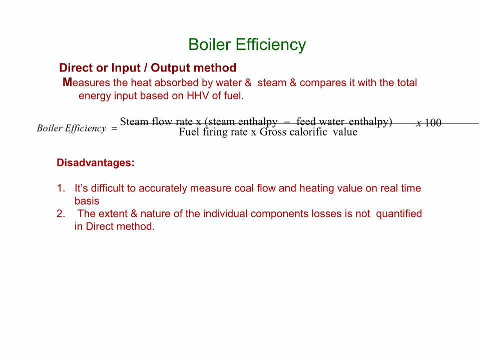
Boiler EfficiencyDirect or Input / Output method Measures the heat absorbed by water & steam & compares it with the total
energy input based on HHV of fuel.
Disadvantages:
1. It’s difficult to accurately measure coal flow and heating value on real time basis
2. The extent & nature of the individual components losses is not quantified in Direct method.
Fuel firing rate x Gross calorific valuex 100Boiler Efficiency
Steam flow rate x (steam enthalpy feed water enthalpy)

Boiler Efficiency
Indirect method or Loss method –
The efficiency of a boiler equals 100% minus the losses. Thus, if the losses are known the efficiency can be derived easily.
This method has several advantages:
1.Errors are not so significant; for example. if the losses total 10% then an error of 1.0% will affect the result by only 0.1 %,
2. The individual components losses are quantified.
The losses method is now the usual one for boiler efficiency determination.
Boiler Efficiency = 100 - Losses in %
The unit of heat input is the higher heating value per kg of fuel. Heat losses from various sources are summed & expressed per kg of fuel fired.
Different Boiler Losses

Operator Controllable Losses – Dry Flue Gas & Unburnt Carbon/CO Loss
Boiler Losses Typical values
Dry Gas Loss 5.21
Unburnt Loss 0.63Hydrogen Loss 4.22Moisture in Fuel Loss 2.00Moisture in Air Loss 0.19Carbon Monoxide Loss 0.11Radiation/Unaccounted Loss 1.00
Boiler Efficiency 86.63
Boiler Efficiency…
Commonly used standards
• ASME PTC 4 (1998) Boilers
• ASME PTC 4.2 (Coal Pulverizers)
• ASME PTC 4.3 (Air Heaters)
• DIN standards
• BS EN 12952-15:2003

Dry flue gas loss Calculation
The only components of a fuel which burn to form dry products of combus-
tion are the carbon and sulphur. Of these two carbon has the greater significance, so for the present ignore the sulphur. The carbon can burn to either carbon dioxide or carbon monoxide thus:
(a) Carbon to carbon dioxide C + 02 = CO2
So masses = 12 + 32 = 44
44 kg of C02 contains 12 kg carbon.
So 1 kg of CO2 contains12/44kg of carbon, i.e. 3/11 kg carbon.
(b) Carbon to carbon monoxide 2C + 02 = 2C0
So masses = 24 + 32 = 56 .
56 kg of CO contains 24 kg carbon.
So 1 kg of CO contains 24/56 kg of carbon, i.e. 3/7 kg of carbon.

Dry flue gas loss• Total dry flue gas = kg carbon x (dry flue gas/kg carbon burned) Total Dry flue gas• So dry flue gas/kg carbon burned = ----------------------------- kg carbon in flue gasThe total dry flue gas consists of the sum of all the dry constituents, i.e. CO2% + 02% + N2% +CO%, and they will add up to 100 kg mol. For example, suppose the percentage by volume of the various constituents is:
CO2 15.0%; 02 4.4%; N2 80.5%; CO 0.l% Then the Relative Mass of each is:
Contituent Vol% Moecular mass Relative Mass CO2 15.0 × 44 = 660 O2 4.4 × 32 = 140,8N2 80,5 × 28 = 2254.0CO 0.1 × 28 = 2.8 _______________________________________________________________ 100 3057.6Therefore 3057.6kg of gas=100kgmole

Dry flue gas lossThus, to revert to the dry flue gas loss, the total dry flue gas equals the sum of the percentage by
volume of the CO2, O2, N2 and CO and is equal to 100 kg moles
Hence dry flue gas/kg carbon burned =100/ (kg carbon in flue gases) kg mol
It was shown earlier that the amount of carbon in the flue gas is 3/11 kg for each kg of CO2 and 3/7 kg for each kg of CO.
100
So dry flue gas/kg of carbon burned= ---------------------------- kg moles
3CO2%/11 + 3CO%/7
But the CO2% and CO% in the expression are in terms of mass of gas, whereas the gas analysis is usually in terms of volume of dry gas. Therefore the CO2% by volume must be multiplied by 44 to give the corresponding relative mass. Similarly the CO% by volume must be multiplied by 28. 100
So dry flue gas/kg of carbon burned= --------------------------------------- kg moles
44x 3CO2%/11 + 28x 3CO%/7
where CO2% and CO% are in terms of volume
100
Dry flue gas/kg of carbon burned= --------------------------------------- kg moles
12 (CO2 + CO)

Dry flue gas loss
Carbon burned= C/100 - C in A
Where, C = % carbon in the fuel. C in A = carbon in rough ash and dust, in kg/kg fuel
100
Dry flue gas = -----------------------( C/100 - C in A) kg moles/per kg fuel
12 (CO2 + CO)
There is a further complication. S in fuel is almost all burned to SO2 . Normally this effect can be ignored unless the sulphur content is very high, but if it is desired to allow for it the expression becomes:
100
Dry flue gas = -----------------------( C/100 + S/267 - C in A) kg moles/per kg fuel
12(CO2 + CO)
Where S = % sulphur in fuel.
The ratio of the atomic weights of carbon to sulphur = 1/2.67
Equation for mass of dry flue gas may be simplified where CO in flue gas is less than 50ppm by ignoring CO
Mass of dry flue gas = (C+ S / 2.67 – 100* C in A ) / 12 CO2 kg moles/per kg fuel
The sensible heat loss per unit mass of fuel Sh = dry flue gas x kg mol Cp gas x (T - t) kJ/kg.
Where kg mol Cp = kilogram molecular specific heat = 30.6 kJ/kg mol
T = A/H gas outlet temperature in C.
t = Temperature at F.D . duct inlet in C
Dry Flue Gas Loss % = (Sh / (GCV of Fuel * 4.2)*100)
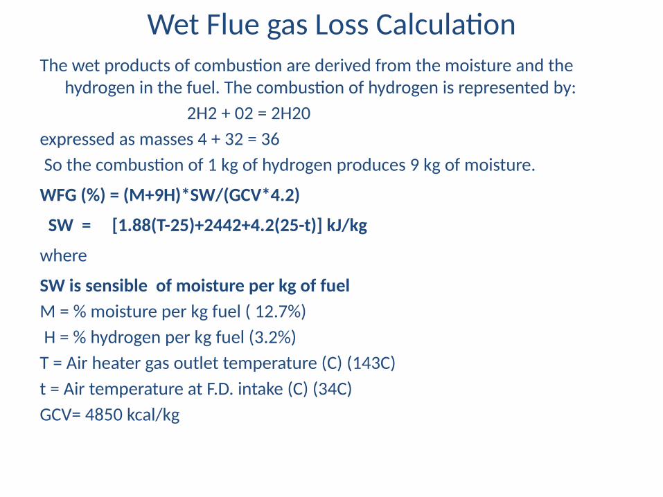
Wet Flue gas Loss CalculationThe wet products of combustion are derived from the moisture and the
hydrogen in the fuel. The combustion of hydrogen is represented by:
2H2 + 02 = 2H20
expressed as masses 4 + 32 = 36
So the combustion of 1 kg of hydrogen produces 9 kg of moisture.
WFG (%) = (M+9H)*SW/(GCV*4.2)
SW = [1.88(T-25)+2442+4.2(25-t)] kJ/kg
where
SW is sensible of moisture per kg of fuel
M = % moisture per kg fuel ( 12.7%)
H = % hydrogen per kg fuel (3.2%)
T = Air heater gas outlet temperature (C) (143C)
t = Air temperature at F.D. intake (C) (34C)
GCV= 4850 kcal/kg

Moisture in combustion air loss (kJ/kg fuel)=
)2
a -Cin _ AM [
C S CO CO 100 267
3.034N
2
Ma *h*1.88*(Tfg Tair )
M a =Dry air for combustion kg/kg of fuel
h =kg moisture per kg dry air
N2, CO2, CO=% volume in dry gas C, S=% in fuel
Answer WFG Loss = 5.35%

13
Combustible in ash loss (kJ/kg of fuel) =
cA * 33820 100
c= % of carbon in dry ash
A= Mass of ash kg/kg of fuel
CV of carbon burnt to CO2 = 33820 kJ/kg (8077.8 kcal/kg) or
Loss due to Unburned carbon in ash (kcal/kg)=
[cA*8077.8] 100Loss in (%) = [cA*8077.8]*100 = [cA*8077.8] 100*GCV GCV20% of total ash constitute as bottom ash 80% of total ash constitute as fly
ash to be considered for computing (c) carbon percentage in dry ash
Compute Boiler efficiency loss % due to C in Ash Where c = 0.8 % , Ash 35% & GCV is 3500

Unburned gas (CO) loss (kJ/kg fuel)=
23717 kJ/kg = CV of burning 1 kg of carbon in CO to CO2
CO2, CO=% volume in dry gas
C, S=% in fuel
100 2672
in _ AS
28 3(CO12
* [7CO C )] * 23717
kj/kg* ( C CO
)
Loss due to C in ash=0.65%
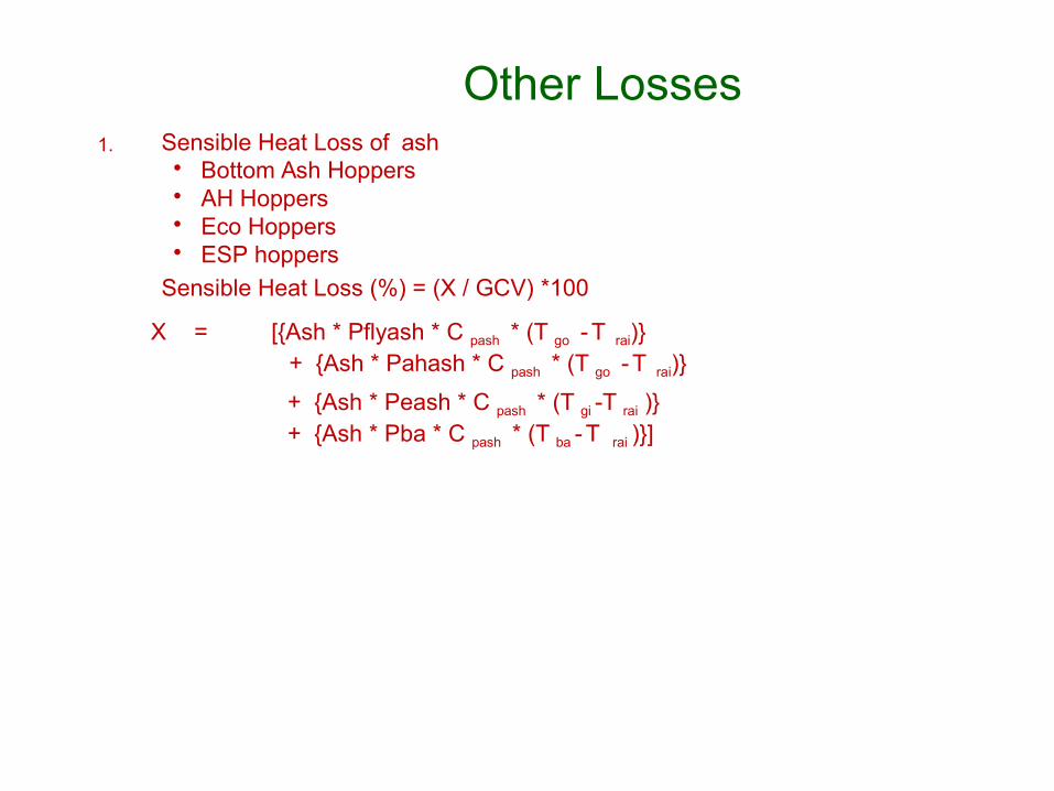
Other Losses1. Sensible Heat Loss of ash
• Bottom Ash Hoppers• AH Hoppers• Eco Hoppers • ESP hoppers
Sensible Heat Loss (%) = (X / GCV) *100
X = [{Ash * Pflyash * C pash * (T go -T rai)}+ {Ash * Pahash * C pash * (T go -T rai)}
+ {Ash * Peash * C pash * (T gi -T rai )}+ {Ash * Pba * C pash * (T ba -T rai )}]

Other Losses…
3. Coal Mill Reject Loss due to Mill Rejects = X / (Coal Flow * GCV * 1000) X = [Rejects * (CVREJECT + CpREJECT (Tmillout – Trai))* 100 ]
Where• Coal Flow• Coal Mill Rejects• GCV of Coal• CV of Rejects• Mill Outlet Temp Tmillout
• Reference Temperature Trai
• Specific Heat of Rejects CpREJECT
Other Losses4. Radiation Loss
Actual radiation and convection losses are difficult to assess because of particular emissivity of various surfaces.
Usually an insulation audit is done separately and is not a part of boiler efficiency test.

Factors affecting Boiler efficiency include
• Design• Coal Quality• Operating parameters
➢ Mill Performance - PF Fineness➢ Burner-to-burner PF balance➢ Excess Air Level➢ Water Chemistry➢ Boiler loading
• Component condition➢ AH Performance➢ Boiler Air Ingress➢ Furnace / Convective section Cleanliness➢ Insulation➢ Quality of Overhauls

Efficiency Vs Moisture
.in Coal
AssumptionsExit Gas Temp - Constt. Fuel Moisture - 20.5 % Excess Air - 20 %GCV - 3700 kal/kg
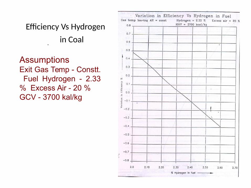
Efficiency Vs Hydrogen
. in Coal
AssumptionsExit Gas Temp - Constt. Fuel Hydrogen - 2.33 % Excess Air - 20 %GCV - 3700 kal/kg

Efficiency Vs HHV of.Coal
AssumptionsExit Gas Temp - Constt. Fuel Moisture - Constt Fuel Hydrogen - Constt Excess Air - 20 %GCV - 3700 kal/kg
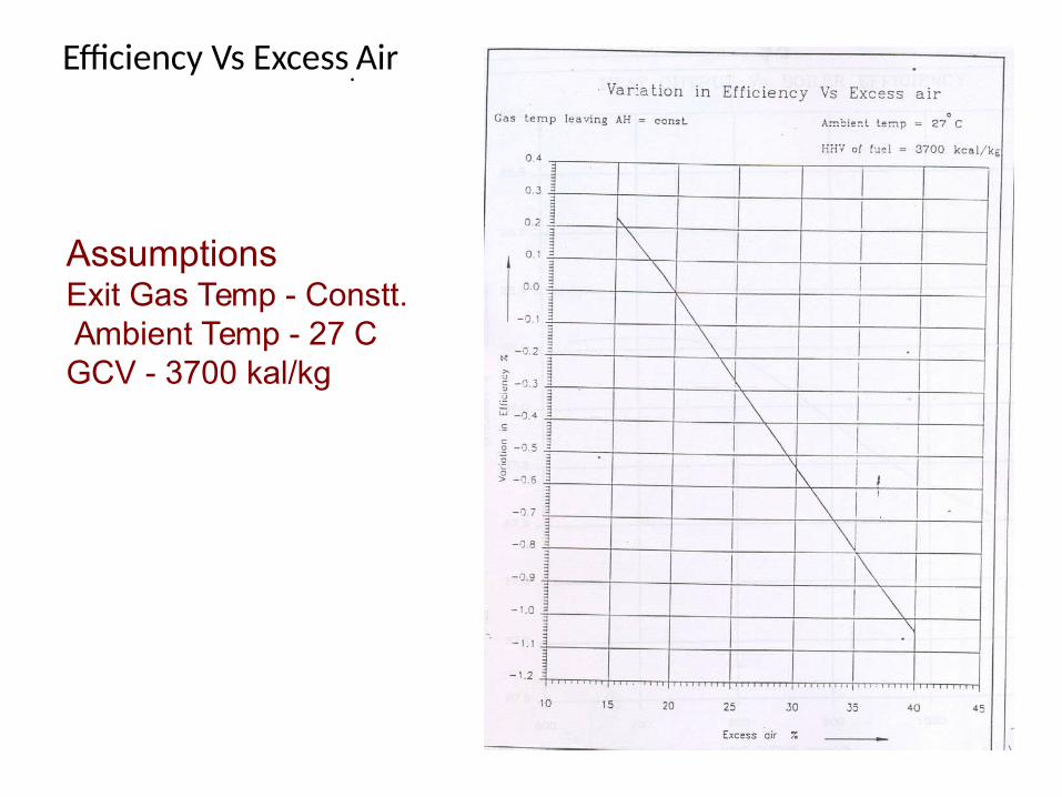
Efficiency Vs Excess.Air
AssumptionsExit Gas Temp - Constt. Ambient Temp - 27 C GCV - 3700 kal/kg
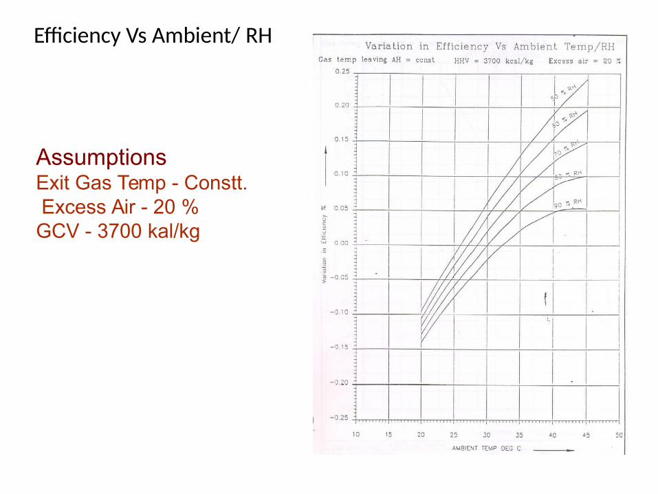
Efficiency Vs Ambient/ RH
AssumptionsExit Gas Temp - Constt. Excess Air - 20 %GCV - 3700 kal/kg

Impact of coal quality on Boiler Efficiency
–Loss due to Moisture and Hydrogen in coal• Moisture in coal
–Every 1% increase in moisture decreases the Boiler Efficiency by 0.1-0.2%
• Hydrogen in Coal–Every 1% increase in hydrogen content decreases the
boiler efficiency by 1.5-2%•Coal GCV
--100Kcal/Kg change in GCV impact the boiler efficiency
0 .3 - 0.5%–Sensible heat due to ash
• Every 1% increase in ash content decreases the boiler efficiency by 0.02%.

EFFICIENCY MEASUREMENT
Objective:
•To identify potential problem and improvement areas
• Identifying reasons for boiler inefficiency
•To verify the feedback from online instruments
• Root cause analysis of different problems
•Statutory requirements

Boiler Efficiency Measurement
Parameters required for evaluation of Boiler Efficiency
AH exit FG O2 / CO2 /CO
AH exit FG temp
Primary / Secondary air temp at AH inlet
Dry/Wet bulb temperatures
Ambient pressure, bar (abs)
Proximate Analysis & GCV of Coal
Combustibles in Bottom Ash and Fly ash

TEST CONDITIONS
All tests are to be conducted at full load at the optimum set of operating
parameters to the extent possible. The operating conditions for each test run are as follows
• Furnace wall blowers and the air heater soot blowers are operated prior to the efficiency test The soot blowing cycle is completed at least an hour before testing to ensure roughly the same level of furnace cleanliness in all the tests.
• No furnace or air heater soot blowing is done during the test.
• Unit operation is kept steady for at least 60 minutes prior to the test.
• Main Steam pressure and temperature and Reheat Steam temperature are set as close to design values as possible.

TEST CONDITIONS Cond-----
• Continuous Blow-down, Intermittent Blow-down is not operated during the test.
• No mill change over is done during the test.
• The test is abandoned in case of any oil support during the test period.
• Bottom ash hopper de-ashing is done prior to the test stabilization period.
• Economiser hopper de-ashing or Bottom hopper de-ashing is not done during the test.

Proximate Coal Analysis – ‘As Fired’
Units
Moisture %
Ash %
Volatile Matter %
Fixed Carbon %
Gross Calorific Value kcal/kg
Parameters
Avg. Flue Gas O2 - AH Out %
Avg. Flue Gas CO2 - AH Out %
Avg. Flue Gas CO - AH Out ppm
Avg. Flue Gas Temp - AH Out C
Avg. Primary Air to AH Temp In C
Avg. Secondary Air to AH Temp In C
Total Secondary Air Flow T/hr
Total Primary Air Flow T/hr
Design Ambient / Ref Air Temp C
Wet Bulb Temp C
Dry bulb Temp C
Barometric Pressure mmHgC
Unburnt C in Bottom Ash %
Unburnt C in Flyash %
% of Flyash to Total Ash %
% of Bottom ash to Total Ash %
Parameters required for Boiler Efficiency Computation
Variables:
Coal analysis Lab test
UBC In FA & BA Lab test
FG composition Offline mst
Temperature Field mst
Flow/Diff Press Field mst

Field Measurements / Sampling
The following field measurements / sampling are done simultaneously during the boiler test.
• Flue Gas Composition (O2 / CO2 /CO) & Temperature - Air
Heater Outlet
• Ambient air-conditions using psychrometer
• ‘As fired’ coal sample from feeder inlet chutes of all running feeders
• 4) Fly ash Sample for unburnt carbon from ESP hoppers
• 5) Bottom ash Sample for unburnt carbon from ash hoppers / grinders
Air Heater Outlet - Flue Gas Composition & Temperature
The test ports in flue gas duct at AH outlet are made as per ASME PTC 19.10 for a grid measurement. The number of measurement points would vary with duct configuration and size.

Sampling Ports in Flue Gas Ducts
100mm
Sampling Point for Flue Gas Composition (4X3 grid)

Thermocouples
Ports
Gas Side Probes
Air Side Probes
Traverse Ports
5d/6+id/2+i
dAdd to probe length
d/6+i

Flue Gas Sampling Train
Flue Gas Composition Measurement

A1
A2
A3
Probe 1
Ports
FG Temperature Measurement by Grid system
A1
A2
A3
Probe 2
A1
A2
A3
Probe 3
Flue Gas Temperature Measurement
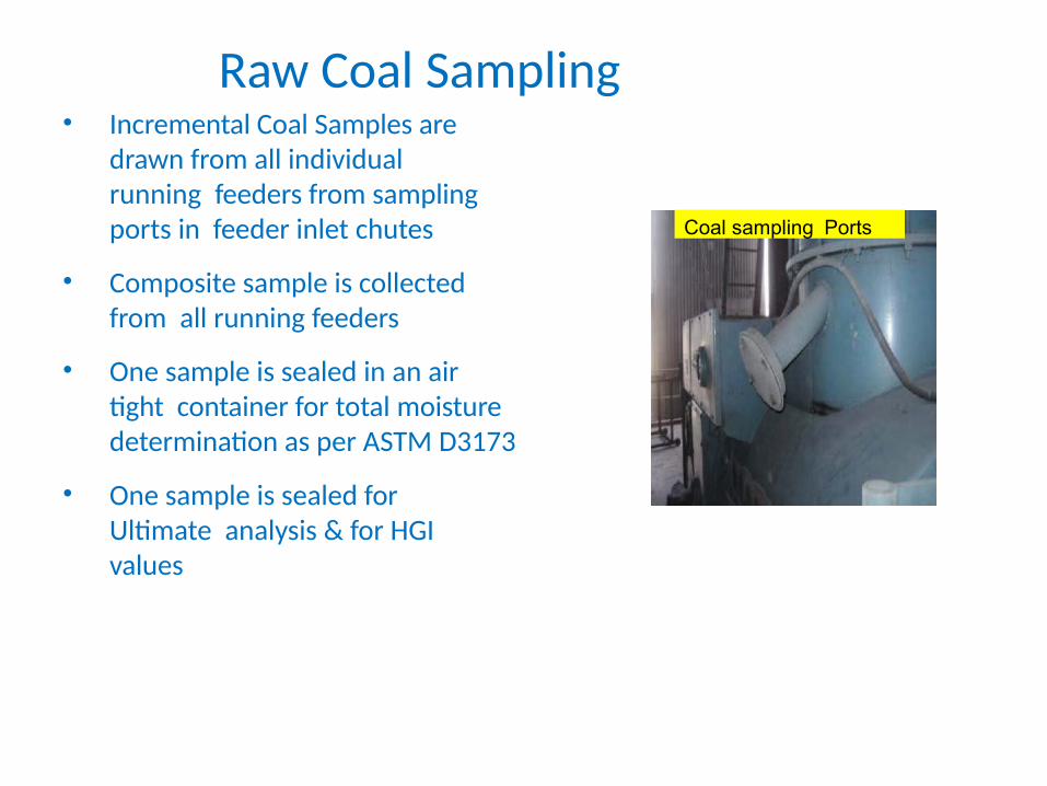
Raw Coal Sampling• Incremental Coal Samples are
drawn from all individual running feeders from sampling ports in feeder inlet chutes
• Composite sample is collected from all running feeders
• One sample is sealed in an air tight container for total moisture determination as per ASTM D3173
• One sample is sealed for Ultimate analysis & for HGI values
Coal sampling Ports

As fired coal sampling point in feeder inlet pipe
Raw coal sampling for boiler performance analysis

Ash SamplingFly Ash Sampling Methodology
• Samples to be collected under stable operating conditions at full load only. Allow operation to stabilize for an hour after mill change over etc.
• For routine sampling of fly ash, samples are to be collected from hoppers in the first two rows of ESPs.
• In each row, samples from left side, right side and middle hoppers are to be collected. The sample size should be around 1 Kg from each hopper.
• Samples collected from hoppers are mixed thoroughly to make a gross sample. Thereafter laboratory sample is separated by repeated coning & quartering of gross sample.
• During the boiler efficiency test, the hoppers from where samples are to be drawn should be evacuated and then only the flyash samples collected under test conditions.
• Samples then air dried/oven dried and tested for LOI (Combustible in ash) by Chemical lab in a furnace

Fly Ash Sampling For special test
A convenient method for representative fly ash sampling during the test involves collecting fly ash from the gas stream using a High Volume sampling probe at economizer outlet on both sides of the boiler.
The flue gas is sucked using an air aspirator and passed through a cylinder containing filter paper that catches the fly ash in collection canister.
One probe is traversed on either side simultaneously during the test and fly ash sample is collected separately from left and right side.

4. In Situ Fly ash Sampler (HVS) Probe
• Used for Isokinetic Fly ash sampling to estimate Unburnt carbon (UBC) in Fly ash
Result & Analysis
• All measured data is compiled in separate sheet.
• Grid average values are taken for CO2,O2, CO & temperatures
• Average Wet & Dry Bulb temperatures are taken
• Coal Proximate , GCV & unburned carbon in ash are compiled.
• Coal carbon & hydrogen values are computed using Seyler Dulong Formulae.
• There is ready XL- spread sheet to compute different losses & compute boiler efficiency.
• Efficiency & losses are compared with design value.
• From the losses value improvement plan can be targeted.
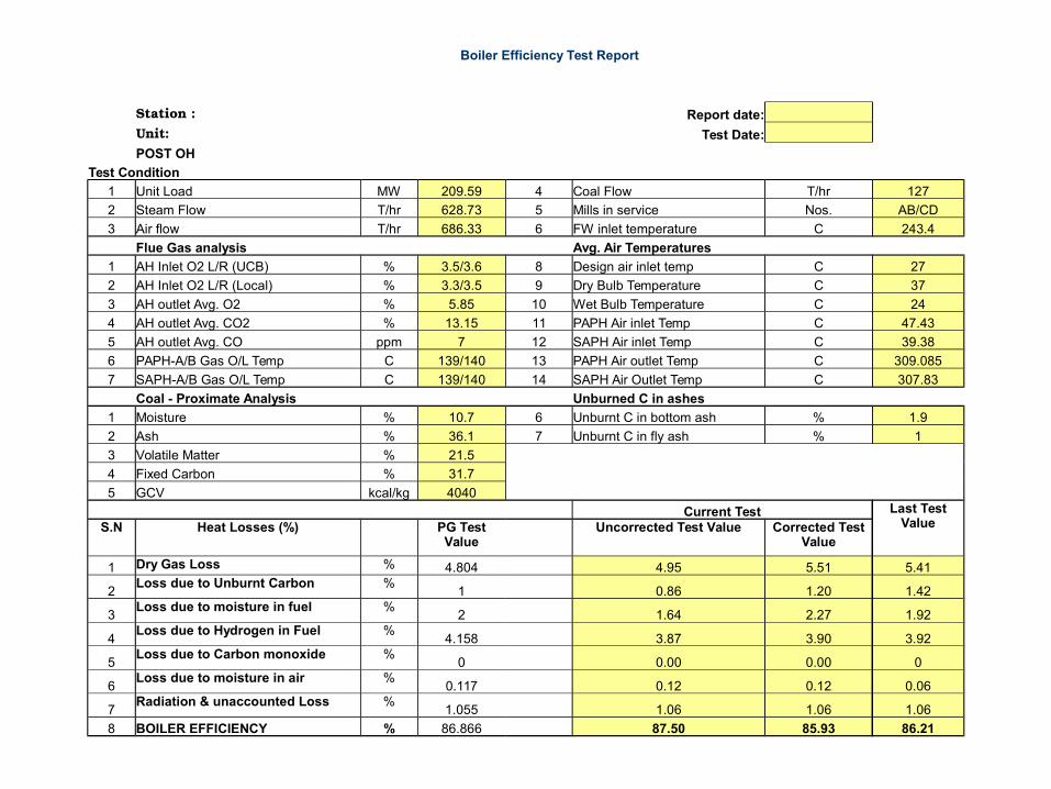
Boiler Efficiency Test Report
Station : Report date:
Unit: Test Date:
POST OH
Test Condition
1 Unit Load MW 209.59 4 Coal Flow T/hr 127
2 Steam Flow T/hr 628.73 5 Mills in service Nos. AB/CD
3 Air flow T/hr 686.33 6 FW inlet temperature C 243.4
Flue Gas analysis Avg. Air Temperatures
1 AH Inlet O2 L/R (UCB) % 3.5/3.6 8 Design air inlet temp C 27
2 AH Inlet O2 L/R (Local) % 3.3/3.5 9 Dry Bulb Temperature C 37
3 AH outlet Avg. O2 % 5.85 10 Wet Bulb Temperature C 24
4 AH outlet Avg. CO2 % 13.15 11 PAPH Air inlet Temp C 47.43
5 AH outlet Avg. CO ppm 7 12 SAPH Air inlet Temp C 39.38
6 PAPH-A/B Gas O/L Temp C 139/140 13 PAPH Air outlet Temp C 309.085
7 SAPH-A/B Gas O/L Temp C 139/140 14 SAPH Air Outlet Temp C 307.83
Coal - Proximate Analysis Unburned C in ashes
1 Moisture % 10.7 6 Unburnt C in bottom ash % 1.9
2 Ash % 36.1 7 Unburnt C in fly ash % 1
3 Volatile Matter % 21.5
4 Fixed Carbon % 31.7
5 GCV kcal/kg 4040
Current Test Last Test ValueS.N Heat Losses (%)
PG Test Value
Uncorrected Test Value Corrected Test Value
1 Dry Gas Loss % 4.804 4.95 5.51 5.41
2Loss due to Unburnt Carbon %
1 0.86 1.20 1.42
3Loss due to moisture in fuel %
2 1.64 2.27 1.92
4Loss due to Hydrogen in Fuel %
4.158 3.87 3.90 3.92
5Loss due to Carbon monoxide %
0 0.00 0.00 0
6Loss due to moisture in air %
0.117 0.12 0.12 0.06
7Radiation & unaccounted Loss %
1.055 1.06 1.06 1.06
8 BOILER EFFICIENCY % 86.866 87.50 85.93 86.21
Reduction in Dry Gas loss
Factors affecting furnace Heat Transfer :
•include Furnace wall condition,
• Combustion Heat release rate, Emissivity, absorptivity and thermal conductivity of deposits,
•Ash dust loading,
• Pulverised fuel fineness,
• Mill Combination (Top, Middle, Bottom),
• Air regime for combustion etc.

• Operation at optimum excess air – High O2 ~ High DFG
• Cleanliness of boiler surfaces – Dirty tubes ~ High EGT
• Cleaning of air heater surfaces and proper heating elements
• Reduction of tempering air to mill
• Reduction in air ingress
• Representative Measurements
Reduction in Dry Gas loss

Air-in-leakage
Furnace Outlet
ZirconiaO2 Probe
AHSea
l Lkg
ESP
Expansion Joints
Part of the boiler leakage air aids the combustion process; but the air that leaks
into the boiler in the low temperature zones causes only a dilution of the flue gas.
Boiler Air Ingress
1. Significant leakage reduces the need for secondary air, resulting in lower heat transfer in air heaters and high exit gas temperatures.
2. Leakage from penthouse and ductwork affects reading of zirconia probes at Eco outlet.

Air ingress is quantified by the increase in oxygen % in flue gas; ID fan margins & temperature drop of the flue gas from air heater outlet to ID fan discharge provide
an indication of the same.
O2
%
Oxygen % at various locations in boiler10
8
6
4
2
0
Furn Outlet AH Inlet AH Outlet ID outlet
210 M W 210 M W 500 M W210 M W
Boiler Air Ingress
• O2 measurement at Gooseneck, Eco outlet, AH Inlet, AH Outlet
and ID fan outlet• Air tightness test by furnace / ducts pressurization• Proper inspection after removing insulation• Thickness survey of ducts by D metering‐• Comprehensive repairs in ducts & hoppers• Replacement of Expansion joints during overhauls

HVT - High Velocity Thermocouple Probe - A Diagnostic Tool
• To establish furnace gas exit temp profile
• To establish CO & O2 profile at furnace exit
• To confirm proper distribution of fuel & air
• To quantify air ingress between furnace outlet and AH inlet
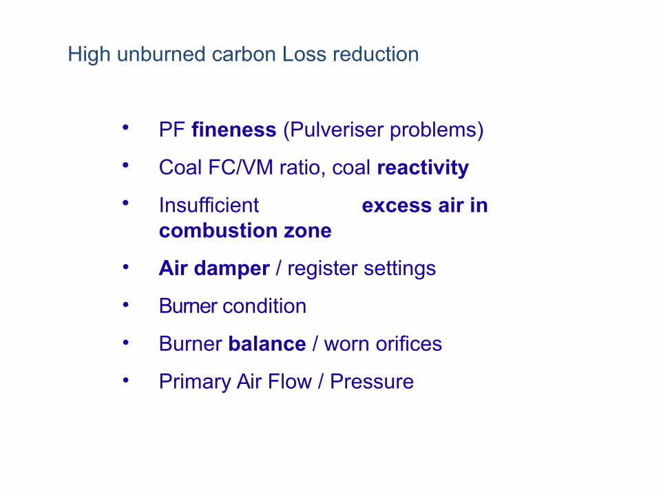
High unburned carbon Loss reduction
• PF fineness (Pulveriser problems)
• Coal FC/VM ratio, coal reactivity
• Insufficient excess air in combustion zone
• Air damper / register settings
• Burner condition
• Burner balance / worn orifices
• Primary Air Flow / Pressure

Parameters that indicate overall plant performance
Heat rate is the common measure of system efficiency in a steam power plant. It is defined as "the energy input to a system divided by the electricity generated, in kW.“ typically in Kcal/kWh,
Mathematically:
Input Energy(Kcal/hr)
Heat Rate = Out Put Power (KW)
Heat rate is simply the inverse of efficiency.
Increase in plant efficiency, would lower heat rate.
What this means is that the lower the heat rate, the better is your plant running .
When calculating plant heat rate, the energy input to the system is the chemical energy in the fuel.
Chemical Energy of Fuel =Total Fuel Used (Kg/hr) x Higher Heating Value (HHV)(Kcal/Kg)

The power generated is simply the gross or net generation in kW.
If gross generation is used, then the resultant heat rate is the gross unit heat rate.
If net generation is used, then the resultant heat rate is net unit heat rate.
Net Generation= Total Generation- APC
Parameters that indicate overall plant performance

Parameters that indicate overall plant performance
GTCHR : It is defined as heat energy used by the turbine cycle to
generate one unit of Electrical energy
Gross Turbine Cycle Heat rate (GTCHR) test is the measure of efficiency of a Steam turbine cycle.
Turbine Cycle Heat Rate (kcal/kWh) =
(Heat Added to Feed Water + Heat added to SH Attemperation +
Heat Added CRH + Heat added to RH Attemperation) / Gross load
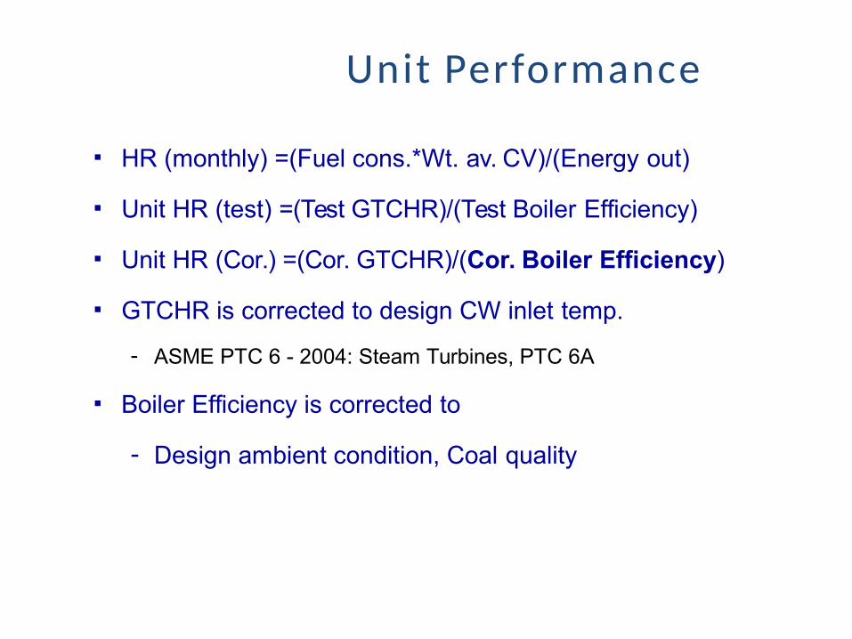
Unit Performance
▪ HR (monthly) =(Fuel cons.*Wt. av. CV)/(Energy out)
▪ Unit HR (test) =(Test GTCHR)/(Test Boiler Efficiency)
▪ Unit HR (Cor.) =(Cor. GTCHR)/(Cor. Boiler Efficiency)
▪ GTCHR is corrected to design CW inlet temp.
- ASME PTC 6 - 2004: Steam Turbines, PTC 6A
▪ Boiler Efficiency is corrected to
- Design ambient condition, Coal quality

Effect of Boiler side Parameters (Approx.)
2009-10
One power sector Expenditure Fuel Cost
36552 Crores29462 Crores (~ 80% of Total)
1 kcal reduction ~ 1.2 T/day saving in coal in 200 MW unit @ 90% PLF & 3600 GCV; CO2 reduction ~ almost 1.25 times coal saved
Parameter Deviation Effect on Heat Rate
Excess Air per % O2 7.4 kcal/kWh
Exit Gas Temp per oC 1.2 kcal/kWh
Unburnt Carbon per % 10-15 kcal/kWh
Coal Moisture per % 2-3 kcal/kWh
Boiler Efficiency per % 25 kcal/kWh

Specific Coal Consumption
• Sp. Coal Consumption is defined as amount of coal required generate one unit of electricity.
Sp. Coal= (Coal consumed/ Units Generated)= (UHR/GCV)UHR can also be calculated as (Sp. Coal* coal GCV)
• It is dependant on coal GCV as well as Unit performance’Suppose Hypothetically GCV of coal=3500 kcal/kg Boiler Efficiency= 100% Turbine Efficiency =100% There is no efficiency lossWhat shall be the HR & Sp. Coal consumption?
Answer
• Unit Heat Rate= 859.85 KWH
• Sp Coal = 0.25 Kcal/Kwh

Typical plant losses