Embed Size (px)
Citation preview
Body Composition Procedures Manual
January 2006

iii
TABLE OF CONTENTS
Chapter Page
1 OVERVIEW OF BODY COMPOSITION ..................................................... 1-1 1.1 Overview of Dual Energy X-Ray Absorptiometry ............................. 1-1 1.2 Personnel............................................................................................. 1-2 1.3 Flow of Body Composition Exam ...................................................... 1-3
2 EQUIPMENT/SUPPLIES/MATERIALS ....................................................... 2-1
2.1 Description of Equipment for DXA.................................................... 2-1
2.1.1 Hologic QDR 4500A........................................................... 2-1 2.1.2 QDR System Operations ..................................................... 2-3 2.1.3 Supplies ............................................................................... 2-3 2.1.4 Radiation Badges ................................................................ 2-3
2.2 Maintenance/Repair of Equipment for DXA...................................... 2-4
2.2.1 DXA Bone Densitometer Service Report ........................... 2-4
2.3 Calibration of Equipment for DXA .................................................... 2-5
3 PROTOCOL .................................................................................................... 3-1
3.1 Introduction to the Examination ......................................................... 3-1 3.2 Explanation of DXA ........................................................................... 3-1 3.3 QDR 4500A System Operation .......................................................... 3-3
3.3.1 Startup Procedures for Hologic QDR (Start of Session)..... 3-3 3.3.2 End of Session Shutdown Procedures for QDR.................. 3-5 3.3.3 End of Day Shutdown Procedures for QDR ....................... 3-5
3.4 Examinee Preparation for DXA.......................................................... 3-5
3.4.1 Measurement of Weight and Height to Determine Body
Mass Index .......................................................................... 3-5 3.5 Whole Body DXA Scan...................................................................... 3-10
3.5.1 Selecting an SP.................................................................... 3-10 3.5.2 Selecting the Type of Scan.................................................. 3-12 3.5.3 Completing the Scan ........................................................... 3-13

iv
TABLE OF CONTENTS (continued)
Chapter Page
3.6 AP Lumbar Spine Scan....................................................................... 3-15 3.6.1 Selecting the SP................................................................... 3-15 3.6.2 Selecting the Type of Scan.................................................. 3-15 3.6.3 Positioning the SP ............................................................... 3-16 3.6.4 Positioning the C-Arm ........................................................ 3-17 3.6.5 Scanning.............................................................................. 3-18
3.7 Proximal Femur Scan.......................................................................... 3-21
3.7.1 Selecting the Type of Scan.................................................. 3-21 3.7.2 Positioning the SP ............................................................... 3-22 3.7.3 Positioning the C-Arm ........................................................ 3-24 3.7.4 Scanning.............................................................................. 3-26 3.7.5 Panniculus (Belly Fat Pad).................................................. 3-28
3.8 DXA Scan Data .................................................................................. 3-29
4 DATA ENTRY SCREENS.............................................................................. 4-1
4.1 Shared Exclusion Questions ............................................................... 4-1 4.2 Weight/Height Entry Screen............................................................... 4-7 4.3 Safety/Exclusion Questions 2 ............................................................. 4-9 4.4 DXA Whole Body Data Capture Screen ............................................ 4-17 4.5 DXA AP Spine Scan Data Capture Screens ....................................... 4-22 4.6 DXA Proximal Femur Data Capture Screens ..................................... 4-25 4.7 DXA Component Status ..................................................................... 4-28 4.8 Session PickUp List ............................................................................ 4-31 4.9 Session Preview Report ...................................................................... 4-32 4.10 Room Log ........................................................................................... 4-33 4.11 Close Exam......................................................................................... 4-34
5 REFERRALS AND REPORT OF FINDINGS ............................................... 5-1
5.1 Observation Referrals ......................................................................... 5-1 5.2 Report of Findings for Body Composition ......................................... 5-3
5.2.1 Sample Preliminary Report of Findings.............................. 5-4
v
TABLE OF CONTENTS (continued)
Chapter Page
6 QUALITY CONTROL.................................................................................... 6-1 6.1 Equipment and Room Set-Up Checks ................................................ 6-1
6.1.1 Daily.................................................................................... 6-1 6.1.2 Three Times Per Week (1st, 3rd, and 5th days of
work week).......................................................................... 6-2 6.1.3 Weekly ................................................................................ 6-2 6.1.4 Start of Stand....................................................................... 6-2 6.1.5 End of Stand........................................................................ 6-3
6.2 Procedures for Completing QC Scans ................................................ 6-3
6.2.1 Hologic Anthropomorphic Spine Phantom (HASP) ........... 6-3 6.2.2 Step Phantom ...................................................................... 6-9 6.2.3 Radiographic Uniformity Test (Old Air Scan).................... 6-12 6.2.4 Slim-line Whole Body Phantom ......................................... 6-19 6.2.5 Hologic Femur/Hip Phantom (Weekly Scan) ..................... 6-24 6.2.6 Circulating HASP (HSP Q-96) ........................................... 6-29 6.2.7 Circulating Block Phantom (Hologic Block Phantom
NH #1)................................................................................. 6-30 6.2.8 Hologic Whole Body Phantom #008 .................................. 6-31
6.3 Using Auto Scan at Start of Stand ...................................................... 6-33 6.4 QC Scan Checklists ............................................................................ 6-36
6.4.1 Instructions for Completing Weekly QC Scan Checklist.... 6-36 6.4.2 Instructions for Completing Start of Stand QC Scan
Checklist.............................................................................. 6-36 6.4.3 Instructions for Accessing Blank QC Checklist Forms....... 6-37
6.5 Data Entry Screens for QC on Equipment.......................................... 6-37
6.5.1 Daily QC Checks................................................................. 6-39 6.5.2 Weekly QC Checks ............................................................. 6-39 6.5.3 Start of Stand QC Checks ................................................... 6-40 6.5.4 End of Stand QC Checks..................................................... 6-42 6.5.5 Incomplete QC Checks ....................................................... 6-42

vi
TABLE OF CONTENTS (continued)
List of Appendixes
Appendix Page A BODY COMPOSITION (DXA) SCRIPTS..................................................... A-1 B SAFETY/EXCLUSION QUESTIONS (SPANISH TRANSLATION) .......... B-1 C SET-UP AND TEAR-DOWN PROCEDURES FOR BODY COMPOSITION ROOM ................................................................................. C-1 D DXA BONE DENSITOMETER SERVICE REPORT ................................... D-1 E START OF STAND QC SCAN CHECKLIST ............................................... E-1 F WEEKLY QC SCAN CHECKLIST ............................................................... F-1 G PROCEDURE FOR SECURING THE QDR 4500A FOR TRAVEL............. G-1 H PROCEDURE FOR SETTING UP THE QDR 4500A FOR OPERATIONS. H-1 I POWER FAILURE PROCEDURES FOR DXA ............................................ I-1
List of Tables
Table 1-1 Age groups and gender for body composition ................................................. 1-2 1-2 Pregnancy status information for body composition by age and gender ......... 1-2
List of Figures
Figure 2-1 Hologic Densitometer QDR4500A.................................................................. 2-1 2-2 Instrument Control Panel on the QDR 4500A................................................. 2-2 2-3 Laser warning label.......................................................................................... 2-2 2-4 Laser locator label............................................................................................ 2-3

vii
TABLE OF CONTENTS (continued)
List of Figures (continued) Figure Page
3-1 Hologic power module right side panel ........................................................... 3-4 3-2 Instrument control panel .................................................................................. 3-8 3-3 Scan table mattress (top view) ......................................................................... 3-9 3-4 Selecting ‘Perform Exam’................................................................................ 3-10 3-5 Patient selection screen .................................................................................... 3-11 3-6 Operator field for initials ................................................................................. 3-11 3-7 Scan selection screen ....................................................................................... 3-12 3-8 Whole Body Scan Parameters screen .............................................................. 3-13 3-9 Whole Body scan image .................................................................................. 3-14 3-10 Exit Exam/New Scan window box .................................................................. 3-14 3-11 AP Lumbar Spine Scan selection screen ......................................................... 3-15 3-12 AP Lumbar Spine Scan Parameters screen ...................................................... 3-16 3-13 C-arm positioning for AP spine scan ............................................................... 3-17 3-14 Spine Scan window.......................................................................................... 3-18 3-15 Properly positioned AP spine........................................................................... 3-19 3-16 Repositioning the spine image ......................................................................... 3-20 3-17 Left Hip Scan Selection screen ........................................................................ 3-21 3-18 Scan Selection screen for proximal femur scan ............................................... 3-22 3-19 SP positioning for femur scan.......................................................................... 3-23 3-20 Foot placement against hip scan positioning fixture........................................ 3-24 3-21 Starting point and reposition mark for femur scan .......................................... 3-25
viii
TABLE OF CONTENTS (continued)
List of Figures (continued) Figure Page
3-22 Hip scan window ............................................................................................. 3-26 3-23 Repositioning the femur................................................................................... 3-27 3-24 Properly aligned and rotated femur scan ......................................................... 3-28 3-25 Data displayed after analysis (1)...................................................................... 3-29 3-26 Data displayed after analysis (2)...................................................................... 3-30 4-1 Shared exclusion questions (1) ........................................................................ 4-1 4-2 Exclusions for another component................................................................... 4-2 4-3 Shared exclusion questions (weight 1) ............................................................ 4-3 4-4 Shared exclusion questions (weight 2) ............................................................ 4-4 4-5 Shared exclusion questions (pregnancy exclusion) ......................................... 4-5 4-6 Shared exclusion questions (no pregnancy question) ...................................... 4-6 4-7 Shared exclusion questions (required response) .............................................. 4-6 4-8 Weight/height entry screen .............................................................................. 4-7 4-9a Weight/height information transferred from body measures ........................... 4-8 4-9b Weight/height information transferred from CV fitness.................................. 4-8 4-10 Entering the weight/height information into the screen................................... 4-8 4-11 Safety/exclusion questions............................................................................... 4-9 4-12 Safety/exclusion questions (contrast radiography) .......................................... 4-11 4-13 DXA Component Status (Data Effect) ............................................................ 4-12 4-14 Safety/exclusion questions (nuclear medicine studies).................................... 4-13 4-15 Safety/exclusion questions (femur scan questions) ......................................... 4-14

ix
TABLE OF CONTENTS (continued)
List of Figures (continued) Figure Page
4-16a Safety/exclusion questions (excluded from femur scan) ................................. 4-15 4-16b Safety/exclusion questions (right hip only) ..................................................... 4-15 4-17 Safety/exclusion questions (nuclear medicine studies).................................... 4-16 4-18 DXA data capture (1)....................................................................................... 4-17 4-19 DXA data capture (2)....................................................................................... 4-18 4-20 DXA data capture (comments on scan) ........................................................... 4-19 4-21 DXA data capture (scan not completed) .......................................................... 4-20 4-22 HP message box............................................................................................... 4-21 4-23 HP error message ............................................................................................. 4-21 4-24 DXA data capture (AP spine scan) (1) ............................................................ 4-22 4-25 DXA data capture (AP spine scan) (2) ............................................................ 4-23 4-26 DXA data capture (AP spine scan) (3) ............................................................ 4-24 4-27 DXA data capture (femur scan) (1) ................................................................. 4-25 4-28 DXA data capture (femur scan) (2) ................................................................. 4-26 4-29 DXA data capture (femur scan) (3) ................................................................. 4-27 4-30 DXA component status (required comments).................................................. 4-28 4-31 DXA component status .................................................................................... 4-29 4-32 Session preview ............................................................................................... 4-31 4-33 Session Preview Report ................................................................................... 4-32 4-34 Room log for body composition ...................................................................... 4-33 4-35 Close exam....................................................................................................... 4-34

x
TABLE OF CONTENTS (continued)
List of Figures (continued)
Figure Page
5-1 Menu to select observation referral.................................................................. 5-1 5-2 Pick list of SPs in current session .................................................................... 5-2 5-3 Observation referral in body composition ....................................................... 5-2 5-4 Observation referral from other components in physician’s referral review box ................................................................................................................... 5-3 5-5 Sample Report of Findings for body composition ........................................... 5-5 6-1 QDR main window .......................................................................................... 6-3 6-2 Daily QC Setup box......................................................................................... 6-4 6-3 System self-test ................................................................................................ 6-5 6-4 System test passed ........................................................................................... 6-5 6-5 Spine Phantom QC image................................................................................ 6-6 6-6 Auto QC passed ............................................................................................... 6-6 6-7 Spine Phantom QC – plot for BMD................................................................. 6-7 6-8 Spine Phantom QC – plot for BMC................................................................. 6-8 6-9 Step Phantom Setup window ........................................................................... 6-9 6-10 Step Phantom scan ........................................................................................... 6-10 6-11 Step Phantom Evaluation completed successfully........................................... 6-11 6-12 Step Phantom QC completed, press ‘Continue’............................................... 6-11 6-13 Selecting Radiographic Uniformity from patient list....................................... 6-12 6-14 Operator box for initials................................................................................... 6-13 6-15 Selecting Whole Body in the select scan type screen ...................................... 6-13

xi
TABLE OF CONTENTS (continued)
List of Figures (continued)
Figure Page
6-16 Radiographic Uniformity scan parameters screen ........................................... 6-14 6-17 Radiographic Uniformity test .......................................................................... 6-15 6-18 Selecting Radiographic Uniformity for SD ..................................................... 6-16 6-19 Selecting Radiographic Uniformity for SD results .......................................... 6-17 6-20 High Air global stats SD.................................................................................. 6-18 6-21 Low Air global stats SD................................................................................... 6-18 6-22 Slim-line whole body phantom fully assembled.............................................. 6-20 6-23 Selecting Slim-Line WB Phantom scan........................................................... 6-21 6-24 Operator box for initials................................................................................... 6-21 6-25 Selecting Whole Body in the select scan type screen ...................................... 6-22 6-26 Slim-Line scan parameters screen ................................................................... 6-22 6-27 Selecting Hologic Femur/Hip Phantom from patient menu............................. 6-24 6-28 Operator box for initials................................................................................... 6-25 6-29 Selecting Right Hip in the scan selection screen ............................................. 6-25 6-30 Hologic Femur/Hip Phantom scan parameters screen ..................................... 6-26 6-31 Machine scanning Femur/Hip phantom........................................................... 6-27 6-32 Exit exam/new scan window box .................................................................... 6-28 6-33 Layout of whole body phantom – top view ..................................................... 6-32 6-34 Layout of whole body phantom – side view.................................................... 6-33 6-35 Selecting Auto Scan from QDR main menu.................................................... 6-34 6-36 Number of times to run scan............................................................................ 6-35

xii
TABLE OF CONTENTS (continued)
List of Figures (continued)
Figure Page
6-37 Quality Control reminder message box ........................................................... 6-37 6-38 Utilities menu to select quality control ............................................................ 6-38 6-39 Quality Control log-on..................................................................................... 6-38 6-40 Quality Control daily checks ........................................................................... 6-39 6-41 Quality Control weekly checks (1) .................................................................. 6-40 6-42 Quality Control weekly checks (2) .................................................................. 6-40 6-43 Quality Control stand checks (1) ..................................................................... 6-41 6-44 Quality Control stand checks (2) ..................................................................... 6-41 6-45 Quality Control end of stand check ................................................................. 6-42 6-46 Quality Control incomplete entry .................................................................... 6-43

1-1
1. OVERVIEW OF BODY COMPOSITION
Body composition will be evaluated in the current National Health and Nutrition Examination Survey (NHANES) by anthropometry, and dual energy X-ray absorptiometry (DXA) in addition to the femur and AP spine scan. These methods will be used to (1) monitor secular trends in overweight prevalence; (2) describe the prevalence of obesity; and (3) examine the relationship between overweight and obesity and other examination measures, including blood pressure, glucose intolerance, and a battery of indicators for cardiovascular disease.
1.1 Overview of Dual Energy X-Ray Absorptiometry
DXA will be used to assess overall skeletal changes that often occur with age by measuring bone mineral content (BMC) and bone mineral density (BMD). In addition, total body fat and lean muscle mass measurements can give insight into the influence of age, sex, and race/ethnicity on the skeleton relative to these measures. DXA measurements can be used to determine the prevalence of osteopenia and osteoporosis. DXA measurements can also be used to provide information on early gender and ethnic changes in the rate of bone accretion and to determine the age when skeletal accretion ceases and when peak bone mass occurs. This information can be used to implement effective and timely measures with the objective of maximizing peak bone mass. Such measures may include calcium supplementation, dietary fortification, or programs promoting dairy products and other calcium and vitamin D rich foods. This information can also be used to assess the impact of factors such as diet or lifestyle on measures of bone status in various minority populations.
The femur and AP spine scans have been added to the NHANES body composition data
collection in 2005. Data obtained from both the femur and anterior-posterior (AP) spine scans are considered gold standards for diagnosing osteoporosis. Collection of data from the DXA femur scan could be used to provide estimates of the prevalence of osteoporosis in the U.S. Additionally, these data could be compared to the NHANES III femur data to track progress toward the Healthy People 2010 Objective 2.9, to reduce the overall numbers of people with osteoporosis. Collection of data from the AP spine scan would provide a more complete evaluation of skeletal health.
1-2
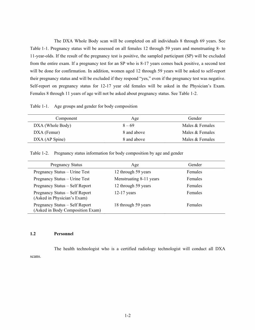
The DXA Whole Body scan will be completed on all individuals 8 through 69 years. See Table 1-1. Pregnancy status will be assessed on all females 12 through 59 years and menstruating 8- to 11-year-olds. If the result of the pregnancy test is positive, the sampled participant (SP) will be excluded from the entire exam. If a pregnancy test for an SP who is 8-17 years comes back positive, a second test will be done for confirmation. In addition, women aged 12 through 59 years will be asked to self-report their pregnancy status and will be excluded if they respond “yes,” even if the pregnancy test was negative. Self-report on pregnancy status for 12-17 year old females will be asked in the Physician’s Exam. Females 8 through 11 years of age will not be asked about pregnancy status. See Table 1-2.
Table 1-1. Age groups and gender for body composition
Component Age Gender DXA (Whole Body) 8 – 69 Males & Females DXA (Femur) 8 and above Males & Females DXA (AP Spine) 8 and above Males & Females
Table 1-2. Pregnancy status information for body composition by age and gender
Pregnancy Status Age Gender Pregnancy Status – Urine Test 12 through 59 years Females Pregnancy Status – Urine Test Menstruating 8-11 years Females Pregnancy Status – Self Report 12 through 59 years Females Pregnancy Status – Self Report (Asked in Physician’s Exam)
12-17 years Females
Pregnancy Status – Self Report (Asked in Body Composition Exam)
18 through 59 years Females
1.2 Personnel
The health technologist who is a certified radiology technologist will conduct all DXA scans.

1-3
1.3 Flow of Body Composition Exam
The body composition exam will begin with the whole body DXA scan(s), followed by the AP spine scan, and lastly the femur scan. Participants will receive a maximum of three DXA scans. Under no circumstances should a whole body scan be repeated. If a problem occurs during the whole body scan, it should be documented in the ISIS Data Capture screen and/or a UFO if necessary.

2-1
2. EQUIPMENT/SUPPLIES/MATERIALS
2.1 Description of Equipment for DXA
2.1.1 Hologic QDR 4500A
The Hologic QDR 4500A (Figure 2-1) is a fan beam X-ray bone densitometer, which uses two different energy levels produced by an energy tube to estimate bone mineral content (BMC) and bone mineral density (BMD). The QDR uses a low level of X-rays, and under standard operating conditions, the entrance dose to the examinee for a whole body scan is less than 1 mR (a standard X-ray is approximately 35 mR).
Figure 2-1. Hologic Densitometer QDR4500A
The densitometer produces ionizing radiation in the form of X-rays and uses laser radiation
to position scans; however, the radiation exposure is so low that no shielding of the room or of health technologists is required.
The X-ray ON indicator is an amber light located in the lower right corner of the instrument
control panel (see Figure 2-2). When the X-ray lamp is lit, X-rays are being produced.

2-2
The Emergency Stop Button is a round red button at the right end of the instrument control
panel that is used for emergencies. When this button is pressed, the X-rays and the table are disabled and scanning stops immediately. Pulling on the button resumes normal operation.
Press down on the button to stop the scan.
Pull up on the button to resume normal operation.
Figure 2-2. Instrument Control Panel on the QDR 4500A
Laser Positioning - The Laser-On Lamp is an amber light above the Laser switch on the
Instrument Control Panel. It alerts the user that the laser position indicator is active. The laser position indicator unit produces 1 mW laser emission. The examinee and technologist should avoid looking directly into the beam, or placing reflective objects in the path of the beam.
The QDR 4500 Elite includes a laser safety feature that turns the laser off if the distance
between the top (right side) of the table is less than approximately 15.5 inches from the laser light spot. This feature is there to help prevent shining the laser light in the examinee’s eyes. Figure 2-3 shows the laser warning label located on the scanner arm.
Figure 2-3. Laser warning label

2-3
Arrows marked Laser Aperture mounted on the scanner arm note the location of the laser beam. Figure 2-4 shows the laser locator label.
Figure 2-4. Laser locator label
2.1.2 QDR System Operations
See Section 3.3 in Chapter 3 for Start-up and Shut-down Procedures for the QDR System. See Appendix I for Power Failure Procedures.
2.1.3 Supplies
Completion of the AP spine and femur scans will require two additional pieces of accessory equipment. A large square cushion will be used for positioning the SP for the AP spine scan. (See Section 3.6 for detailed procedures.) Also, the Hologic hip positioning fixture will be used for positioning the SP for the femur scan. (See Section 3.7 for detailed procedures.)
2.1.4 Radiation Badges
Health technologists operating the densitometers are required to wear radiation badges for dosimetry processing. A control badge is placed in the room on the computer cart beside the densitometer.

2-4
2.2 Maintenance/Repair of Equipment for DXA
If the chief technologist needs to contact Hologic for repair, the contact number and other important information are listed below:
Call Hologic customer support at 1-800-321-4659.
You will need the model number and the serial number for your machine.
Model number for all MECs is QDR 4500.
Serial number for MEC 1 is 45575.
Serial number for MEC 2 is 45678.
Serial number for MEC 3 is 45700.
2.2.1 DXA Bone Densitometer Service Report
When the Hologic densitometer is serviced or repaired:
The chief technologist will complete a ‘DXA Bone Densitometer Report.’ (See Appendix D.)
Fax a copy of the report to the home office. See Appendix D for specific instructions about names and numbers. The home office will send this to the Quality Control Reading Laboratory.
Fax a copy of the service report completed by the service engineer to the home office when the repair or service is made.
Put a copy of the service engineer’s report and a copy of the DXA Bone Densitometer in the service report binder kept in the DXA room. This binder is used to store the Hologic Customer Service Reports and the DXA Bone Densitometer Service Report forms.
Blank DXA Bone Densitometer Service Report forms are stored electronically in the ISIS system. Open Word, select File/Open, look in the directory for Mecstaff/Blank forms/DXA_serv.doc.

2-5
2.3 Calibration of Equipment for DXA
Refer to Chapter 6 for complete instructions regarding calibration and quality control scanning procedures.

3-1
3. PROTOCOL
3.1 Introduction to the Examination
The technologist should briefly explain the examination when the sample person (SP) is brought into the room. The exam should be explained in more detail as each section is being completed. The objective is to inform the SP about the exam and to position the SP as quickly as possible. Below is a suggested introductory script but the examiner should use his or her own words for this explanation. This is an explanation, not a standard script, so the technologist may adjust the explanation to the level of understanding of the examinee.
Suggested Introduction to Component (English Version): In this room, I’m going to take three scans of your body with this machine. These scans can tell us how strong your bones are and how much fat you have. I will explain each exam in more detail as I go along. Suggested Introduction to Component (Spanish Version): En este cuarto, vamos a hacer dos tipos de exámenes. Un examen nos puede decir qué tan fuertes están sus huesos y cuánta grasa tiene usted. El otro examen mide la cantidad de agua en su cuerpo. Explicaré cada examen en más detalle mientras que lo esté haciendo.
3.2 Explanation of DXA
The technologist is scanning the ID wrist band of the examinee during this explanation. This should be used as a guideline only and the technologist should adjust the explanation to the level of understanding of the SP. The script used for an 8-year-old will be different from the script used for a 60-year-old. The scripts below provide suggested explanations of the body composition exam, as well as each individual scan.
Suggested Explanation of DXA Scans (English Version): It will take about 3 minutes to position you correctly for each scan and another few minutes to take the scans. The scan of your hip and spine will tell us how strong your bones are compared to other people like you, and the scan of your whole body will tell us how much body fat you have. I will explain each scan in more detail as I position you for the scan. I am going to ask you a few questions before I start the exam (SAFETY EXCLUSION QUESTIONS ARE ASKED).

3-2
Please lie down on the table now and get as comfortable as possible. During the scans be as still as possible and do not talk. Suggested Explanation of DXA Scans (Spanish Version): En el primer examen, voy a tomar tres escáneres de su cuerpo con esta máquina. Tomará más o menos 3 minutos ponerle en la posición correcta para cada escáner y otros pocos minutos para tomar los escáneres. El escáner de su cadera y de su columna nos dirá qué tan fuertes están sus huesos comparados con los de otras personas como usted, y el escáner de todo su cuerpo nos indicará cuánta grasa tiene usted en el cuerpo. Le explicaré cada escáner en más detalle mientras que le posicione para el escáner. Le voy a hacer algunas preguntas antes de empezar el examen (SAFETY EXCLUSION QUESTIONS ARE ASKED). Por favor acuéstese sobre la mesa ahora y póngase lo más cómodo(a) posible. Durante los escáneres quédese lo más quieto(a) posible y no hable. Suggested Explanation of Whole Body DXA Scan (English Version): The first scan we will do is the whole body scan. For this scan, please lie still on the table with your arms by your sides. I’m going to position your arms and feet correctly for the scan and then wrap these Velcro straps loosely around your feet to hold them in place. This scan will take about 3 minutes to complete. As the machine scans your body, the table will move up and down and back and forth. This overhead arm will also be moving. Suggested Explanation of Whole Body DXA Scan (Spanish Version): El primer escáner que haremos es un escáner de todo el cuerpo. Para este escáner, por favor acuéstese sobre la mesa sin moverse con los brazos a los lados. Voy a ponerle los brazos y los pies correctamente para el escáner y después le pondré estas cintas “Velcro” no muy apretadas alrededor de los pies para mantenerlos en su lugar. Este escáner tomará más o menos 3 minutos para completarse. Mientras que la máquina toma el escáner de su cuerpo, la mesa se moverá hacia arriba y hacia abajo, y hacia adelante y hacia atrás. Este brazo de arriba también se estará moviendo. Suggested Explanation of AP Spine Scan (English Version): For the spine scan, you will also lie flat on the table, but I’m going to bend your legs at a 90 degree angle at the hip and knee by placing them on this large soft cube-shaped pillow. This scan will take only 30 seconds. You will not feel anything during this scan. Suggested Explanation of AP Spine Scan (Spanish Version): Para el escáner de la columna vertebral, usted también tendrá que recostarse extendido sobre la mesa, pero yo le voy a doblar las piernas en un ángulo de 90 grados en la cadera y las rodillas poniéndolas en esta almohada grande y suave en forma de cubo. Este escáner tomará solamente 30 segundos. Usted no sentirá nada durante este escáner.

3-3
Suggested Explanation of Femur Scan (English Version): The next scan will be of your hip. For this scan, please continue to lie still with your legs flat against the table. I will rotate your left leg inward slightly and then keep it in place using this foot brace. It will take about 30 seconds to complete this scan. You will not feel anything during the scanning. Suggested Explanation of Femur Scan (Spanish Version): El siguiente escáner será para su cadera. Para este escáner, por favor continúe recostado sin moverse con las piernas extendidas sobre la mesa. Voy a moverle la pierna izquierda un poco hacia adentro y después la mantendré en esa posición usando estas bandas para los pies. Tomará más o menos 30 segundos para completar este escáner. Usted no sentirá nada durante este escáner.
3.3 QDR 4500A System Operation
The QDR 4500 system should be turned on at the beginning of the day and off at the end of each session for that day. See Appendix H for setting up the QDR 4500 for operations. Routine startup procedures for the beginning of a session are outlined below in Section 3.3.1. See Appendix G for securing the QDR 4500 for travel. Routine shutdown procedures are outlined in Section 3.3.2. See Appendix I for power failure procedures for DXA.
3.3.1 Startup Procedures for Hologic QDR (Start of Session)
Confirm these settings first.
Check that the POWER ON lamp on the Power Module is lit. (The switch and the lamp are located on the bottom left of the back panel. This light indicates that the system is in standby mode and power is maintained to the signal detector. This eliminates warming up the detector when the system is turned on. This should be left on at all times unless a power failure occurs. See Appendix I for Power Failure Procedures.
COMPUTER POWER switch (1) should be ON. (This is left ON to allow network backup overnight.) See Figure 3-1.
Check that the INSTRUMENT POWER switch (2) on the Power Module right side panel is in the ON position.
X-RAY ENABLE KEY (3) should be OFF. See Figure 3-1.

3-4
Figure 3-1. Hologic power module right side panel
Turning the Hologic QDR System ON (Start of Session Routine Procedure)
NOTE: The X-Ray Enable key is already off.
In the blue screen, select ‘Start’ from the lower left. Select ‘Turn off computer’ and select ‘Turn off.’
The computer will shut down.
(NOTE: The X-RAY ENABLE KEY is already OFF).
At this point, the X-ray table and the computer are both shut down.
Now both should be brought up to begin the session.
Turn the X-RAY ENABLE KEY clockwise to enable production of X-rays.
Push the Computer Power Button (on CPU).When the QDR login screen is displayed, double click on QDR (soccer ball icon).
(If the QDR database has not been backed up a tan Windows box will appear: ‘A backup of your QDR system’s database has not been performed in # days! ... Do you want to perform a system backup now?’ Click ‘No.’)
The X-ray table will turn on and the QDR Main Menu will be displayed.
Log in to ISIS.

3-5
3.3.2 End of Session Shutdown Procedures for QDR
The screen should display the QDR Main Menu.
Turn the X-RAY ENABLE KEY counterclockwise (OFF).
Remove the key and put it in the designated spot.
3.3.3 End of Day Shutdown Procedures for QDR
Click Exit (bottom right corner). Then select ‘Exit QDR without Shutdown’ and click ‘OK.’ Leave at blue screen.
Turn the X-RAY ENABLE KEY counterclockwise (OFF).
Remove the key and put it in the designated spot.
Re-boot ISIS.
3.4 Examinee Preparation for DXA
The SP should be logged into the Integrated Survey Information System (ISIS) as soon as possible after he or she has entered the room.
3.4.1 Measurement of Weight and Height to Determine Body Mass Index
After answering the Shared Exclusion questions, the next screen displayed will be the weight/height data entry screen. See Figure 4-8 (Section 4). If the SP was in the anthropometry (BM) component or cardiovascular (CV) fitness component prior to this test, the weight and height will already be uploaded and displayed on the ISIS screen, along with the component it transferred from (i.e., BM, CV). See Figures 4-9a and 4-9b. If the information is not displayed, you will need to measure the SP’s weight and height using the floor scale and stadiometer in the room. The system will use the weight and height measurements to calculate the body mass index which will determine whether the SP needs the high power whole body scan or not. The same precision to take the weight and height measurements in the anthropometry component must be used in this component.

3-6
3.4.1.1 Weight
Follow these steps to take the SP’s weight: 1. Make sure the scale weighs in kilograms by checking the switch on the underside of
the digital display.
2. Place the scale on the floor.
3. Switch on the scale by pressing the ON button, 888.8 will appear on the digital display.
4. Have the SP remove his or her shoes and any outer clothing such as sweaters, jackets, etc.
5. As soon as the display switches to 0.0, have the SP step on the scale with his or her feet positioned in the center.
6. Ask the SP to stand straight and remain still.
7. Wait about 4 seconds for the weight to display on the digital readout.
8. Record the weight in kilograms in the weight field.
9. Ask the SP to step off the scale. The scale switches off automatically after 30 seconds.
If the SP’s weight is more than 300 pounds, he or she will be excluded from the entire body composition component due to weight limitation of the table. If the SP is greater than 300 pounds, after checking the transferred data in ISIS or weighing, open up the exam for this SP and proceed through the shared exclusion questions. These questions will exclude the SP from the exam. See Section 4.1.

3-7
3.4.1.2 Height
Follow these steps to take the SP’s height: 1. Ask the SP to remove his or her shoes if necessary.
2. Place the stadiometer a few inches away from the wall. Check to be sure the measurement column on the stadiometer is completely inserted into the floorpiece. Pull the sliding top bar section up and open the head piece to allow the SP to step under the head piece.
3. Ask the SP to stand erect on the floorboard with his or her back to the vertical piece of the stadiometer and the wall. The SP should not be leaning against the stadiometer.
4. Ask the SP to evenly distribute weight on both feet. The heels are placed together with the feet pointed slightly outward at a 60 degree angle. The arms hang freely, by the sides of the trunk with palms facing the thighs.
5. Position the head in the Frankfort horizontal plane. The head is in the Frankfort plane when the horizontal line from the ear canal to the lower border of the orbit of the eye is parallel to the floor and perpendicular to the vertical backboard. Many people will assume this position naturally, but for some it may be necessary to make a minor adjustment. If required, gently tilt the head up or down until proper alignment is achieved with the eyes looking straight ahead. Once correctly positioned, ask the SP to inhale deeply and to stand fully erect without altering the position of the heels.
6. Lower the headpiece snugly to the crown of the head with sufficient pressure to compress the hair.
7. Hold the top sliding bar in place at the junction and ask the SP to step out away from the stadiometer.
8. Record the measurement in centimeters (measurements printed on right side of bar) at the orange line on the measuring bar.
If the SP is greater than 6’5”, he or she will be excluded from the whole body scan, due to limitations of the table. After the SP is logged in, check the first ISIS screen to determine if his or her height transferred from another component, or measure it using the stadiometer. If the height exceeds this limit, the SP is excluded from the whole body scan. In the whole body data capture screen, select ‘No’ to ‘Scan Completed’ and check the box ‘too tall for table.’ The exam status will be set to ‘Partial’ due to ‘height limitation on the table.’
3-8
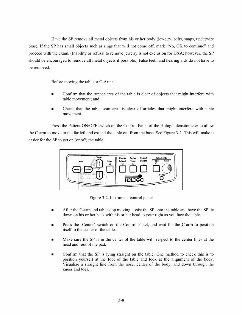
Have the SP remove all metal objects from his or her body (jewelry, belts, snaps, underwire bras). If the SP has small objects such as rings that will not come off, mark “No, OK to continue” and proceed with the exam. (Inability or refusal to remove jewelry is not exclusion for DXA; however, the SP should be encouraged to remove all metal objects if possible.) False teeth and hearing aids do not have to be removed.
Before moving the table or C-Arm:
Confirm that the runner area of the table is clear of objects that might interfere with table movement; and
Check that the table scan area is clear of articles that might interfere with table movement.
Press the Patient ON/OFF switch on the Control Panel of the Hologic densitometer to allow the C-arm to move to the far left and extend the table out from the base. See Figure 3-2. This will make it easier for the SP to get on (or off) the table.
Figure 3-2. Instrument control panel
After the C-arm and table stop moving, assist the SP onto the table and have the SP lie
down on his or her back with his or her head to your right as you face the table.
Press the ‘Center’ switch on the Control Panel, and wait for the C-arm to position itself to the center of the table.
Make sure the SP is in the center of the table with respect to the center lines at the head and foot of the pad.
Confirm that the SP is lying straight on the table. One method to check this is to position yourself at the foot of the table and look at the alignment of the body. Visualize a straight line from the nose, center of the body, and down through the knees and toes.

3-9
Make sure that the SP’s body is entirely within the scan limit borders on the pad. (See Figure 3-3.)
Make sure the SP’s head is within the scan border.
The legs should be positioned together with the feet relaxed. Use a piece of double-sided Velcro around the ankles to support the legs in this position and to reduce movement. As noted earlier, SP’s who are taller than 6’5” will be excluded from the whole body scan due to limitations of the table.
The SP should lie flat on the table without a pillow. If the SP has trouble lying flat due to back problems or difficulty breathing when lying flat, use the radiolucent pillow to support the head. Place a pillowcase over the pillow before putting it on the table. If the pillow does not provide sufficient support, use the radiolucent block or wedge. These may also be used under the knees.
If the SP continues to have difficulty lying flat or with the head slightly supported, exclude him or her from the exam.
Figure 3-3. Scan table mattress (top view)
The SP’s feet should be within the scan limit border. Position the legs and feet, then
place Velcro around the ankles to maintain the position.
Place the SP’s arms straight at his or her sides, palms down, with a separation from the thighs. Verify that the arms are within the scan border. A large SP can place his or her hands vertically next to his or her thighs to ensure that hands and arms remain within the limits. Do not tuck the hands under the body.
There must be a space between the patient’s arms and sides whenever possible.

3-10
3.5 Whole Body DXA Scan
Read and answer all (Shared) Safety Exclusion questions in ISIS. You must complete up to the Data Capture screen in ISIS before performing an exam.
Click the ‘Perform Exam’ icon or ‘Exam’ in the top menu bar and select ‘Perform Exam’ from its drop-down menu. Figure 3-4.
Figure 3-4. Selecting ‘Perform Exam’
3.5.1 Selecting an SP
In the ‘Patient Selections’ screen, enter the SPID from the ISIS screen into the blank white field next to Patient Name, or highlight the SPID from the list of IDs under the Patient Name column. Press ‘OK.’ See Figure 3-5.

3-11
Figure 3-5. Patient selection screen
Enter your initials in the ‘Operator’ field and click ‘OK.’ See Figure 3-6.
Figure 3-6. Operator field for initials

3-12
3.5.2 Selecting the Type of Scan
The next screen will display the types of scans to choose from. In the ‘Scan Selection’ screen select the scan type by clicking on ‘Whole Body’ with the mouse. The scan type is highlighted. See Figure 3-7. Click the ‘Next >>’button.
Note: If the SP was selected for the High Power Whole Body option, select HP Whole Body from the Scan Selection Screen.
Figure 3-7. Scan selection screen
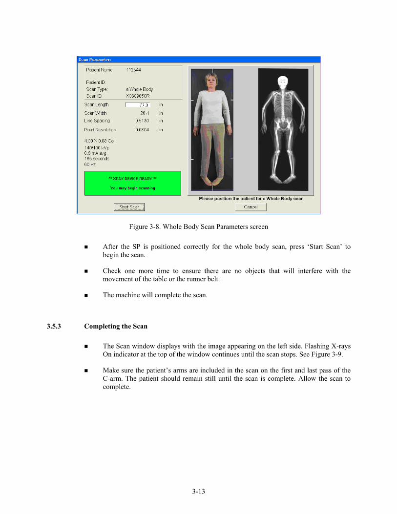
The Whole Body Scan Parameters Screen will display. See Figure 3-8.
Verify the patient name and scan type in the upper left corner.
3-13
Figure 3-8. Whole Body Scan Parameters screen
After the SP is positioned correctly for the whole body scan, press ‘Start Scan’ to
begin the scan.
Check one more time to ensure there are no objects that will interfere with the movement of the table or the runner belt.
The machine will complete the scan.
3.5.3 Completing the Scan
The Scan window displays with the image appearing on the left side. Flashing X-rays On indicator at the top of the window continues until the scan stops. See Figure 3-9.
Make sure the patient’s arms are included in the scan on the first and last pass of the C-arm. The patient should remain still until the scan is complete. Allow the scan to complete.

3-14
Figure 3-9. Whole Body scan image
The analysis will be done later by the QC Reading Lab.
Go to the ISIS screen and complete the DXA Data Entry screen.
Remove the Velcro strap from the SP’s feet and clean it with disinfectant spray.
See Chapter 5 for a description of the information provided to the SPs from this test.
When the exam completes, an Exit/New Scan window box displays. See Figure 3-10.
Figure 3-10. Exit Exam/New Scan window box

3-15
3.6 AP Lumbar Spine Scan
3.6.1 Selecting the SP
If this is the first scan for the SP, click the ‘Perform Exam’ icon or ‘Exam’ in the top menu bar and select ‘Perform Exam’ from its drop-down menu. See Figure 3-4.
If the Whole Body scan has already been performed, click ‘New Scan’ from the Exit/New Exam windows box. See Figure 3-10.
3.6.2 Selecting the Type of Scan
In the ‘Scan Selection’ screen select the scan type by clicking on ‘AP Lumbar Spine’ with the mouse. The scan type is highlighted. See Figure 3-11. Click the ‘Next>>’button.
Figure 3-11. AP Lumbar Spine Scan selection screen
The AP Lumbar Spine Scan Parameters screen will display. See Figure 3-12.

3-16
Figure 3-12. AP Lumbar Spine Scan Parameters screen
Verify the patient name and scan type in the upper left corner. Stop here and position
the patient and the C-arm.
3.6.3 Positioning the SP
The SP should be positioned with his or her head to your right as you face the table. Make sure that the SP is straight and centered on the table and that his or her shoulders are at the upper scan limit hash marks on the long edges of the table, to ensure the spine will be within the scan area.
NOTE: It may be helpful to stand at the head end of the DXA table, reach under the SPs underarms, and gently pull toward you to straighten the spine.
On the control panel, press the center table switch to move the table and C-arm to the center position.
Place the large square cushion under the SP’s lower legs with the thighs as close to a 90° angle to the body as possible.
Have the SP rest his or her arms comfortably at his or her sides.

3-17
3.6.4 Positioning the C-Arm
Locate the SP’s iliac crest.
Using the arm motion controls on the control panel, bring the laser indicator vertical line to approximately 2 inches below the iliac crest. The laser indicator horizontal line should coincide with the midline of the SP. See Figure 3-13. The laser indicator is projected when the motion control is activated.
Figure 3-13. C-arm positioning for AP spine scan

3-18
3.6.5 Scanning
Prior to beginning the scan, confirm that the SP’s body is straight with respect to the laser, the table, and the lines on the table pad.
Press ‘Start Scan’ to begin the scan.
The Scan window displays with the image appearing on the left side. Flashing X-rays On indicator at the top of the window continues until the scan stops.
Figure 3-14. Spine Scan window
Make sure that the spine is centered and straight, there are even amounts of soft tissue
on each side of the entire spine, and that a small amount of the iliac crest is visible in the lower corners of the screen (Figure 3-15). If not, click ‘Reposition Scan’ to stop the scan.
3-19
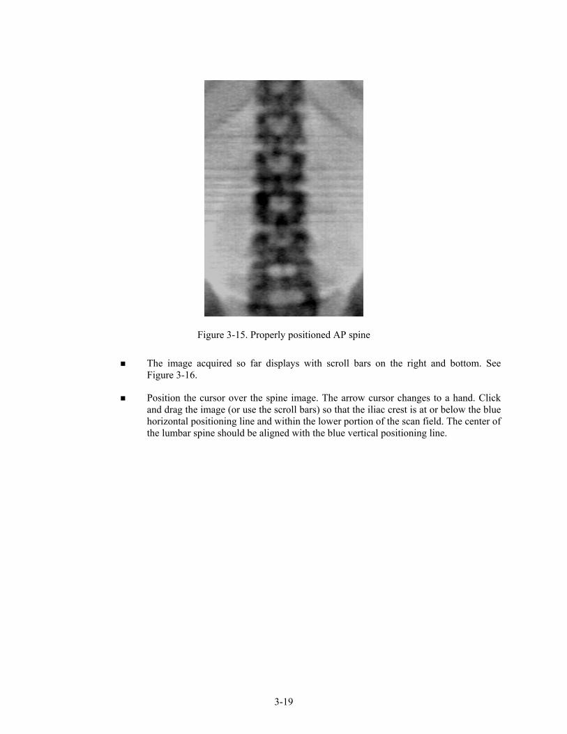
Figure 3-15. Properly positioned AP spine
The image acquired so far displays with scroll bars on the right and bottom. See
Figure 3-16.
Position the cursor over the spine image. The arrow cursor changes to a hand. Click and drag the image (or use the scroll bars) so that the iliac crest is at or below the blue horizontal positioning line and within the lower portion of the scan field. The center of the lumbar spine should be aligned with the blue vertical positioning line.

3-20
Figure 3-16. Repositioning the spine image
If the spine is not straight, move the patient’s upper torso either left or right to
straighten the spine. When the spine is repositioned correctly, click the ‘Restart Scan’ button. The Scan Parameters window displays. Click the ‘Start Scan’ button to start a new scan at the new position. The Scan window displays with a flashing X-rays On message. The image displays.
When you see the ribs attaching at T-12 (See Figure 3-14), click the ‘Stop Scan’ button. When the scan completes, the Exit/New Exam window displays. Figure 3-10.
The analysis will be done later by the QC reading lab.
Go to the ISIS screen and complete the DXA Data Entry screen.
Remove the large square cushion from under the SP’s legs and place in designated spot in the body composition room.
3.6.5.1 Adjusting the Default Length of the AP Spine Scan
For the majority of SP’s, the default length settings for the spine scan will be appropriate and will result in a spine scan that properly shows a small amount of iliac crest in the lower corners of the scan, L1 through L5, and the ribs attaching at T-12 at the top of the scan. However, it is possible that for a tall SP this length may not be adequate to include all necessary points of interest. If during the scout scan
Screen Forthcoming

3-21
it becomes apparent that the default length of the scan will not be adequate, it will be necessary to adjust the default length of the scan. This should be done as follows:
As soon as it is apparent that the length of the scan is not adequate, press ‘Reposition
Scan’ to stop the scan.
Make any adjustments that may be necessary and press ‘Restart Scan’ to accept the new starting position.
The scan parameters screen (see Figure 3-12 shown earlier) will be displayed. To change the scan length, place the cursor in the Scan Length field and type the new length, number 10 and press ‘Start Scan.’ The system may change the number entered to match the pre-programmed step size of the scanning mechanism.
3.7 Proximal Femur Scan
Select ‘New Scan.’ See Figure 3-10.
3.7.1 Selecting the Type of Scan
At the ‘Scan Selections’ screen (Figure 3-17), choose left hip, unless answers to safety exclusion questions warrant using the right hip. ‘Click ‘Next >>‘.
Figure 3-17. Left Hip Scan Selection screen

3-22
The Scan parameters window appears. Figure 3-18. Verify the patient name and scan type in the upper left corner.
Figure 3-18. Scan Selection screen for proximal femur scan
3.7.2 Positioning the SP
The SP should be positioned with his or her head to your right as you face the table. Make sure that the SP is straight and centered on the table. The hip region should be within the two sets of hash marks on either side of the long edge of the table (see Figure 3-19).

3-23
Figure 3-19. SP positioning for femur scan
On the control panel, press the Center Table switch to move the table and C-arm to the
center position.
Place the hip scan positioning fixture on the far left end of the table near the SP’s feet. Align the center of the fixture with the patient’s midline. The leg to be examined should be rotated inward so that the foot can be placed against the positioning fixture and secured with the strap (Figure 3-20). Adjust the abduction of the leg so that the shaft of the femur is parallel with the center of the table.
NOTE: In rotating the leg inward, place one hand above the knee and one hand below the knee and gently rotate the leg to ensure the whole leg is rotated, as opposed to just the lower portion of the leg.
Make sure that the SP’s arms are outside of the scanning area.

3-24
Figure 3-20. Foot placement against hip scan positioning fixture
3.7.3 Positioning the C-Arm
Locate the SP’s greater trochanter. This can be done as described below.
Grasp the leg to be scanned near the ankle and gently rotate the leg inward and outward several times. Press firmly on the outside of the thigh while rotating the leg. You should feel the greater trochanter roll under your fingertips.
If you are not able to feel the trochanter, have the SP bend the leg at the knee and lift (may be necessary to assist the SP). Locate the crease formed at the top of the leg and use this as an approximate location of the greater trochanter.
In both cases, these are approximate location(s) to begin the scan.
Move the C-arm until the laser cross-hair is 2 inches below the level of the greater trochanter and is on the center shaft of the femur (Figure 3-21, see “Starting Point Left” and “Starting Point Right”).
Align the femoral shaft so it is parallel to the horizontal line of the laser.

3-25
Figure 3-21. Starting point and reposition mark for femur scan

3-26
3.7.4 Scanning
Reconfirm that the SP is properly positioned and press ‘Start Scan’ to begin the scan.
The Scan window displays with the image appearing on the left side. Flashing X-rays On indicator at the top of the window continues until the scan stops. The image will appear on the screen, one line at a time from the bottom up. Figure 3-22.
Figure 3-22. Hip scan window
Inspect the image as it is generated. If the hip is positioned correctly, allow the scan to
complete. If the hip is not positioned correctly, click the ‘Reposition Scan’ button to stop the scan.
When the outer edge of the greater trochanter can be identified, press ‘Reposition Scan’ to re-scan.
NOTE: If the scout scan reveals that the SP has a hip replacement or pin, previously not reported, stop the scan and proceed with scan on the other hip, if possible. If this is not possible, discontinue the scan and complete the Femur Scan data entry scan to document the reason for the incomplete scan.
Reposition the image up, down, left or right using the scroll bars or cursor hand to include the entire femoral head, neck, and approximately 3 inches of the shaft (see Figure 3-23, “Reposition Mark”). The new starting point is automatically adjusted to have the correct amount of soft tissue lateral to the greater trochanter.

3-27
Figure 3-23. Repositioning the femur
Press ‘Restart Scan’ to return to the scan parameter screen.
When the scan parameter screen re-appears, press ‘Start Scan’ to repeat the scanning process.
The scanning will start from the corrected starting point. Repeat the re-scan process until acceptable anatomy is shown, then allow the scan to finish. See Figure 3-24 for an example of a properly aligned and rotated femur scan.

3-28
Figure 3-24. Properly aligned and rotated femur scan
The analysis will be done later by the QC Reading Lab.
Go to the ISIS screen and complete the Femur Scan screen. Be sure to inspect thoroughly the scan to include any comments that may be necessary.
Remove the SP’s leg from the hip positioning fixture. Clean the fixture with disinfectant spray and place in designated spot in the Body Composition room.
3.7.5 Panniculus (Belly Fat Pad)
On very obese women (and men), the fat pad of the belly can overlie the head of the femur artificially increasing the BMD. This is a major source of error which will cause the analysis of the scan to be inaccurate.
When presented with an obese SP, gently palpate the area to determine if there will be obesity noise. Ask the SP to hold the fat pad out of the way with their hands by pulling it up and away from the femoral area. If unsure from palpation, start scan, and if obesity noise is present, repeat scan with the panniculus retracted.
Document this on the DXA Proximal Femur Data Capture Screen in the “Other” text box under “Comment on scan” by typing for example “Belly fat pad retracted.”
Lesser trochanter is barely visible
Shaft of femur is straight

3-29
3.8 DXA Scan Data
Analysis of the scans will be done at the QC Reading Center.
Figures 3-25 and 3-26 show the data displayed after the regions of interest are selected and the analysis is completed.
Figure 3-25. Data displayed after analysis (1)

3-30
Figure 3-25 displays the percent fat by region and for the total body. The percent total body fat for the hypothetical SP in the example is 23.6 percent.
Figure 3-26 displays the bone mineral density (BMD) for the SP. In addition, the box below the graph gives the T-score and the Z-score for the BMD for this SP.
Figure 3-26. Data displayed after analysis (2)

4-1
4. DATA ENTRY SCREENS
The generic term “DXA” is used throughout this manual and is meant to refer collectively to all three SP scans—whole body, spine, and femur. In places where a specific answer to one of the shared exclusion or safety exclusion questions will exclude an SP from “DXA,” this generic term represents all SP scans. Other safety exclusion questions are specific to one of the scans (e.g., the question pertaining to a lumbar spine fusion pertains only to the spine scan) and the answer to that question may exclude the SP from that scan. In this case, the specific scan will be referenced by name.
4.1 Shared Exclusion Questions
Due to limitations of the DXA table, SPs will be excluded from certain scans based on height and weight limitations of the equipment. As the SP enters the body composition room, his or her height will be checked using the marker inside the room. If the SP is greater than 6’5”, the SP will be excluded from the whole body scan but not the hip and spine. Select ‘height limitation on the equipment’ as the comment for the whole body section.
Figure 4-1. Shared exclusion questions (1)

4-2
The Shared Exclusion Questions may be answered in several components in the MEC. If these questions have been answered in a previous component in the MEC, the questions and responses will be displayed in read-only format.
If the SP is excluded from this exam based on his or her answers to the Shared Exclusion Questions in another component, the SP would be blocked from body composition by the Coordinator System and the SP would not be sent to this exam.
The Component Status for body composition for this SP would be set to ‘Not Done’ with a comment specific to the reason for exclusion (safety exclusion, physical limitation, etc.).
If you get a ‘Yes’ response to the Shared Exclusion questions, the SP is not excluded immediately. You must ask the remaining Shared Exclusion Questions and press the Next button before the SP is excluded. Other components will use the responses to these questions to determine eligibility.
If the answer to ‘Do you have any amputations of your fingers and toes?’ is No, the SP remains eligible for the exam.
If the response is Yes, the question ‘Where is the amputation?’ has response options of Right, Left, or Both.
SPs are not excluded from the DXA exam based on an amputation, but the system will then display a series of messages about the components that will be excluded due to amputation. Click OK to these messages. See Figure 4-2 where the SP is excluded from CV Fitness due to amputation.
Figure 4-2. Exclusions for another component

4-3
If the answer to the question ‘What is your current weight?’ is less than 275 pounds, the question is disabled and the SP remains eligible for the exam.
Figure 4-3. Shared exclusion questions (weight 1)
If the answer to the question on self-reported weight is between 275 and 300 pounds, the system will display a message: ‘Please check SP weight on portable scale. If weight is greater than 300 pounds, press ‘Close Exam’ and select ‘weight limitation on equipment.’ See Figure 4-3.
Check the SP’s weight on the portable scale in the room. The weight from the portable scale does not have to be entered in the field. NOTE: The portable scale also has a weight limitation of 300 pounds. If the SP weighs more than 300 pounds, ‘supp’ will appear on the display, signaling that the SP exceeds the capacity of the scale.
If the weight is between 275 and 300 leave the self-reported weight in the field and continue with the exam.
If the weight is greater than 300 pounds, select ‘Close Exam.’ See next screen.

4-4
Figure 4-4. Shared exclusion questions (weight 2)
You will need to answer the remaining Shared Exclusion Questions before closing the
exam.
Follow the directions in the message to end the exam. The SP is excluded due to weight restriction on the DXA table. When the remaining questions have been answered, press ‘Close Exam.’ Choose ‘Not Done’ with the comment ‘weight limitation on equipment.’ See Figure 4-4.
Click OK to finish the exam.
If the response to the question ‘How much do you weigh without clothes or shoes?’ is greater than 300 pounds, the system will display a message: ‘Excluded from DXA due to weight limitation on equipment.’
If the self-reported weight is greater than 300 pounds, you do not need to weigh the SP on the portable scales. The SP will be excluded based on this weight.

4-5
When all Shared Exclusion questions are answered, the system will display a series of messages regarding the exclusions to other components based on weight (CV Fitness, CV Exclusion Questions in Physician’s Exam, Balance).
SPs are not excluded from DXA due to a pacemaker or automatic defibrillator. If the response to this question is ‘Yes,’ a series of exclusion messages will be given to indicate that the SP is also excluded from other examination components.
Figure 4-5. Shared exclusion questions (pregnancy exclusion)
If the response to the question ‘Are you currently pregnant?’ is ‘Yes,’ the SP will be
excluded from DXA due to pregnancy status.
The system will go to the next question to determine how many weeks pregnant.
When the next button is pressed, a message will be displayed: ‘Excluded from DXA due to pregnancy status.’ Press OK to this message. See Figure 4-5.
A series of messages will be displayed to indicate exclusion to other components (CV fitness questions in the physician’s exam and CV fitness if weeks pregnant is greater than 12 weeks). Click OK to these messages.
The Component Status will be set to ‘Not done’ with the comment ‘SP pregnant.’
If the SP is male, female older than 60 years, or female 8-17 years, the pregnancy questions will not be displayed. See Figure 4-6. (The question on self-reported pregnancy status for 12 to 17-year-old females will be asked in the physician’s exam.)

4-6
Figure 4-6. Shared exclusion questions (no pregnancy question)
If the response to the question on pregnancy status is ‘No,’ the question on ‘How
many weeks?’ is disabled.
If there are no exclusions based on the Shared Exclusion Questions, press the Next button. The system will advance to the Safety/Exclusion Questions.
Figure 4-7. Shared exclusion questions (required response)
If you have not answered all of the questions before the Next button is pressed, a message will be displayed: ‘Please answer the question.’ ‘How much do you weigh without clothes or shoes?’ See Figure 4-7.

4-7
4.2 Weight/Height Entry Screen
After answering the Shared Exclusion questions, the next screen displayed will be the weight/height data entry screen. See Figure 4-8. If the SP was in the anthropometry (BM) component or cardiovascular (CV) fitness component prior to this test, the weight and height will already be uploaded and displayed on the ISIS screen, along with the component it transferred from (i.e., BM, CV). This information will be grayed out. See Figure 4-9a and 4-9b. If the information is not displayed, measure the SP’s weight and height using the stadiometer and floor scale in the room. Enter these numbers into the white entry fields next to ‘Weight’ and ‘Height.’ See Figure 4-10. For instructions on measuring weight and height see Section 3.5.1.
Figure 4-8. Weight/height entry screen

4-8
Figure 4-9a. Weight/height information transferred from body measures
Figure 4-9b. Weight/height information transferred from CV fitness
Figure 4-10. Entering the weight/height information into the screen The system will use the height and weight measurements to calculate the body mass index
which will determine whether the SP needs the high power whole body scan or not. If the SP has been selected for the high power whole body scan a message will display in the Whole Body Data Capture Screen. See Section 4.4, Figure 4-22.

4-9
4.3 Safety/Exclusion Questions 2
Figure 4-11. Safety/exclusion questions
The Safety/Exclusion Questions should be read exactly as written. Read the entire question
before accepting an answer. If the SP interrupts you before you have completed reading the question, say that you are required to read the entire question before accepting an answer. See Figure 4-11. All Safety/Exclusion questions must be answered before the exclusion status will be displayed.

4-10
The first two items on this screen are technologist observations and are not questions to be asked. The technologist observes if the SP has removed all jewelry and other objects that may interfere with the data. They are not safety exclusions but it may invalidate the results or interpretation of the scan.
The observations are:
1. Has SP removed all jewelry, eyeglasses, hair ornaments, and other objects from the hair and body?
The possible responses and how they should be interpreted are listed below:
Yes: The SP has removed all jewelry and objects that might interfere with the scan. If ‘Yes,’ the SP will not be excluded from DXA.
No, exclude: The SP is unable or unwilling to remove jewelry and objects that might affect the data to a large degree.
No, OK to continue: The SP has not removed all jewelry or other things, but the objects are small. Continue with the scan and make a comment about this. If ‘No, OK to continue’ is selected, check ‘Jewelry or other objects not removed’ from the DXA Data Capture screen.
Don’t Know: The technologist and/or the SP does not know if everything has been removed. This situation should not occur frequently.
2. Does the SP have any amputations other than fingers and toes?
If the response to the observation ‘Does the SP have any amputations other than fingers or toes?’ is ‘No,’ the SP will not be excluded from DXA.
The next five questions are asked as safety exclusion questions and will not flag an exclusion to this component but will be used in the analysis of this component.
3. Do you have any artificial joints, pins, plates, shrapnel, or other types of metal objects in
your body?
4. Do you have any coronary stents or metal suture material in your heart?
5. Are you using an insulin pump or have insulin lines now?
6. Do you have an ostomy, such as an ileostomy or colostomy?
7. Are you wearing a hearing aid now?

4-11
The next few questions may flag an exclusion to part or all of the DXA exam depending on the response.
8. Have you had an X-ray with contrast material such as barium in the last 7 days?
9. Have you had any nuclear medicine studies in the past 3 days?
10. Have you ever fractured your hip, had a hip replacement, or do you have a pin in your hip?
Is it your right hip, left hip, or both?
11. Do you have a lumbar spine fusion?
Figure 4-12. Safety/exclusion questions (contrast radiography)
If the response to the question ‘Have you had an X-ray with contrast material such as
barium in the last 7 days?’ is No, continue with the next questions.
If the response to the question is Yes, the SP will be excluded from DXA.

4-12
Complete the remainder of the questions. When the Next button is pressed, a message will be displayed: ‘Excluded from DXA due to the effect contrast material may have on the data.’ Click OK to this message.
The DXA Component Status will be set to ‘Not Done’ with the comment ‘data effect.’ See Figure 4-13.
Figure 4-13. DXA Component Status (Data Effect)
If the response to the question ‘Have you had any nuclear medicine studies in the past 3 days?’ is No, continue with the next questions.
If the response to the question is Yes, the SP will be excluded from DXA.

4-13
Figure 4-14. Safety/exclusion questions (nuclear medicine studies)
Complete the remainder of the questions. When the Next button is pressed, a message will be displayed: ‘Excluded from DXA due to the effect radionuclides may have on the data.’ Click OK to this message. See Figure 4-14.
The DXA Component Status will be set to ‘Not Done’ with the comment ‘data effect.’

4-14
Figure 4-15. Safety/exclusion questions (femur scan questions)
If the response to the question “Have you ever fractured your hip, had a hip
replacement, or do you have pins in your hip?” is ‘Yes,’ the system will go to the next question to determine which hip the SP is referring to. See Figure 4-15 above.
- If Both is chosen, the SP will be excluded from the femur scan for safety reasons. See Figure 4-16a.
- If Left Hip Only is chosen, the SP will not be excluded from the femur scan. The femur scan will be conducted using the SP’s right hip. See Figure 4-16b.
- If Right Hip Only is chosen, the SP will not be excluded from the femur scan. The femur scan will be conducted using the SP’s left hip as per protocol.

4-15
Figure 4-16a. Safety/exclusion questions (excluded from femur scan)
Figure 4-16b. Safety/exclusion questions (right hip only)

4-16
Figure 4-17. Safety/exclusion questions (nuclear medicine studies)
If the response to the question “Do you have a lumbar spine fusion?” is ‘Yes,’ the SP
will be excluded from the AP spine scan. See Figure 4-17.
If the response to the question is ‘No or Don’t Know,’ the SP will not be excluded from the AP spine scan.

4-17
4.4 DXA Whole Body Data Capture Screen
Figure 4-18. DXA data capture (1)
Figure 4-18 is the ISIS DXA data capture screen.
This screen allows you to check whether or not the scan was completed.
There are no defaults on the screen when it is first displayed.
This screen has check boxes to record any problems in getting a good quality scan. You can check one or more of the following problems.
- SP movement during the exam; - Too tall for table, feet out of scan; - Positioning problem; - Pillow used for head support; - Jewelry or other objects not removed; - Equipment failure; or - Hands positioned along sides, not flat; - Other – open text.

4-18
Figure 4-19. DXA data capture (2)
If the scan is completed, select ‘Yes.’
The system will automatically enter the Archive File name.
The Archive number is D for DXA, 120605 for December 6, 2005 and 01 for the first file to be archived. The file extension is .ARC. See Figure 4-19.
If the scan is completed successfully, the Component Status will be ‘Complete.’

4-19
Figure 4-20. DXA data capture (comments on scan)
During and immediately after the scan, check the scan for quality.
If one or more of the Comments on scan apply, check all that apply. See Figure 4-20.

4-20
Figure 4-21. DXA data capture (scan not completed)
If the DXA scan cannot be completed, select ‘No.’ See Figure 4-21.
If the reason is equipment failure, check that comment.
If there is another reason, enter the reason in the free text box for Other.
If the scan cannot be completed, the DXA component status will be set to Partial. Select the appropriate comment from the list in the drop-down menu. See Figure 4-31.
4-21
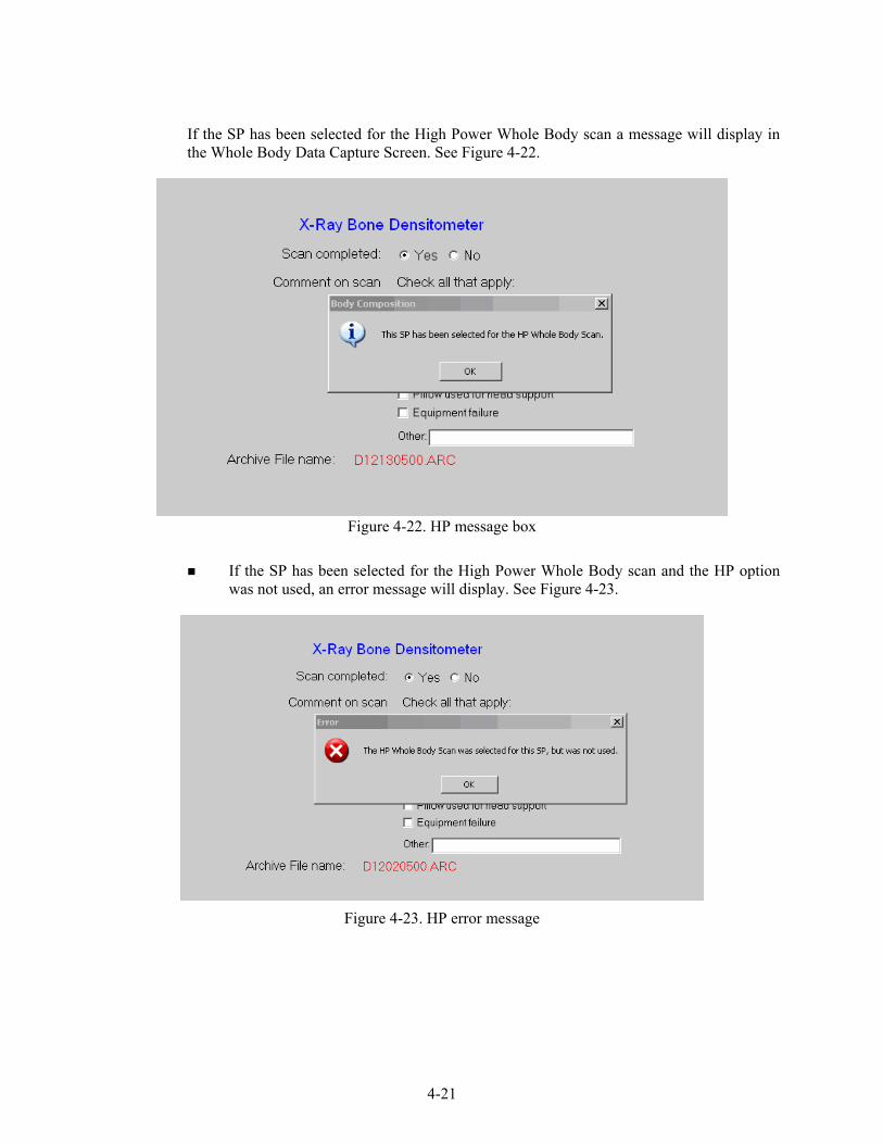
If the SP has been selected for the High Power Whole Body scan a message will display in the Whole Body Data Capture Screen. See Figure 4-22.
Figure 4-22. HP message box
If the SP has been selected for the High Power Whole Body scan and the HP option
was not used, an error message will display. See Figure 4-23.
Figure 4-23. HP error message

4-22
4.5 DXA AP Spine Scan Data Capture Screens
Figure 4-24 is the ISIS DXA data capture screen for the AP spine scan.
This screen allows you to check whether or not the AP spine scan was completed.
Figure 4-24. DXA data capture (AP spine scan) (1)
There are no defaults on the screen when it is first displayed.
This screen has check boxes to record any problems in getting a good quality AP spine scan. You can check one or more of the following problems.
- SP movement during the exam; - Equipment failure; or - Positioning problem; - Other – open text. - Jewelry or other objects not removed;

4-23
If the scan is completed, select ‘Yes.’ See Figure 4-25.
The system will automatically enter the AP spine Archive file name.
Figure 4-25. DXA data capture (AP spine scan) (2)
The Archive number is D for DXA, 121704 for December 17, 2004, and 00 for the
first file to be archived. The file extension is .ARC.
During and immediately after the scan, check the scan for quality.
If one or more of the Comments on the scan apply, check all that apply.

4-24
If the scan cannot be completed, select ‘No.’ See Figure 4-26.
If the reason is equipment failure, check that comment.
Figure 4-26. DXA data capture (AP spine scan) (3)
If there is another reason, either check the appropriate box or enter the reason in the free text box for Other.
Press Enter to proceed to the Femur Scan Screen.

4-25
4.6 DXA Proximal Femur Data Capture Screens
Figure 4-27 is the ISIS DXA data capture screen for the femur scan.
This screen allows you to check whether or not the femur scan was completed.
Figure 4-27. DXA data capture (femur scan) (1)
There are no defaults on the screen when it is first displayed.
This screen has check boxes to record any problems in getting a good quality femur scan. You can check one or more of the following problems.
- SP movement during the exam; - Equipment failure; or - Positioning problem; - Other – open text. - Jewelry or other objects not removed;

4-26
If the scan is completed, select ‘Yes.” See Figure 4-28.
The system will automatically enter the Femur Archive file name.
Figure 4-28. DXA data capture (femur scan) (2)
The Archive number is D for DXA, 121704 for December 17, 2004, and 00 for the
first file to be archived. The file extension is .ARC.
During and immediately after the scan, check the scan for quality.
If one or more of the Comments on the scan apply, check all that apply.

4-27
If the scan cannot be completed, select ‘No.’ See Figure 4-29.
If the reason is equipment failure, check that comment.
Figure 4-29. DXA data capture (femur scan) (3)
If there is another reason, enter the reason in the free text box for Other.
Press ENTER to proceed to the Component Status screen.

4-28
4.7 DXA Component Status
Figure 4-30. DXA component status (required comments)
The completion status for the DXA component is.
Complete 8 through 69 years DXA, femur & spine scans
> 69 years Femur and spine completed
Partial 8 through 69 years At least one scan not completed
> 69 years Femur or spine not completed
Not Done 8 through 69 years None of the 3 protocol scans completed
> 69 years Spine and femur scan not completed
If a comment is not selected when the status is ‘Partial’ or ‘Not Done,’ a message will be displayed: ‘Please select comments.’ See Figure 4-31.
Click OK to this message and select the appropriate comment.
Press the Finish button to end the exam.

4-29
Figure 4-31. DXA component status
If the component status is ‘Partial’ or ‘Not Done,’ the system will require a comment
to be selected from the drop-down menu. See Figure 4-31.
The comments in the drop-down box are:
- Safety exclusion;
- SP refusal;
- No time;
- Physical limitation;
- Communication problem; and
- Equipment failure.

4-30
Other comments in the drop-down box that are not shown in Figure 4-31 are:
- SP ill/emergency;
- Data effect;
- Inability to lie still;
- Interrupted;
- Pain or discomfort;
- Proxy, no information;
- SP moved during the procedure;
- SP pregnant;
- Width exceeds scan table;
- Weight limitation on equipment;
- Urine not collected;
- SP unable to comply;
- Exceeds height limitation;
- Error (technician/software/supplies); and
- Other, specify.

4-31
4.8 Session PickUp List
Figure 4-32. Session preview
The Session Preview box can be accessed from the Toolbar under Reports.
Go to Reports, select Session preview from the menu.
A list of current sessions will be displayed. See Figure 4-32.
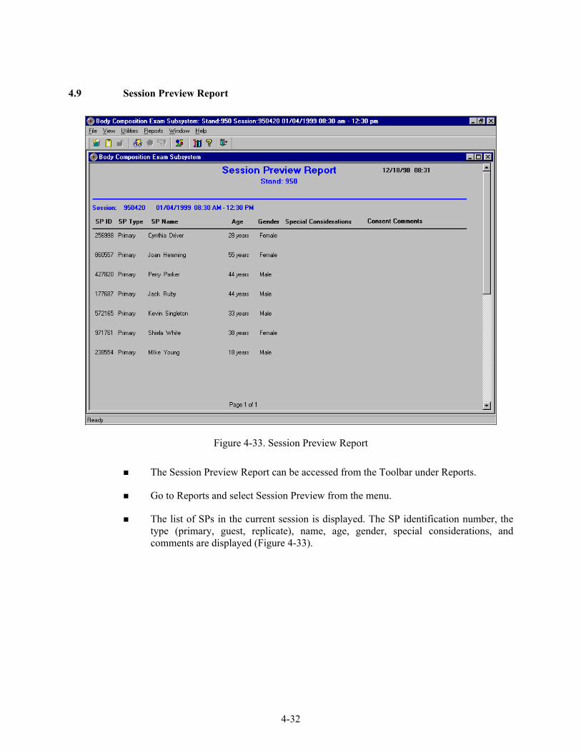
4-32
4.9 Session Preview Report
Figure 4-33. Session Preview Report
The Session Preview Report can be accessed from the Toolbar under Reports.
Go to Reports and select Session Preview from the menu.
The list of SPs in the current session is displayed. The SP identification number, the type (primary, guest, replicate), name, age, gender, special considerations, and comments are displayed (Figure 4-33).
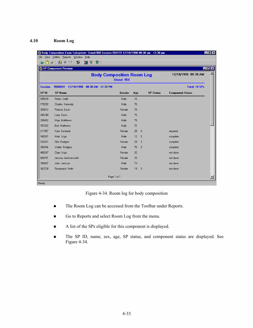
4-33
4.10 Room Log
Figure 4-34. Room log for body composition
The Room Log can be accessed from the Toolbar under Reports.
Go to Reports and select Room Log from the menu.
A list of the SPs eligible for this component is displayed.
The SP ID, name, sex, age, SP status, and component status are displayed. See Figure 4-34.

4-34
4.11 Close Exam
Figure 4-35. Close exam
Any exam may be terminated at any point during the exam (SP becomes ill, changes his or her mind about completing the test).
The ‘Close Exam’ button is used to end the exam abruptly without going through the remaining screens.
Choose a comment and click on Close to end the exam.

5-1
5. REFERRALS AND REPORT OF FINDINGS
5.1 Observation Referrals
Observation referrals are nonemergency situations that may arise in any of the examination rooms in the MEC. Technologists may send an observation referral to the MEC physician if they notice any condition that may be abnormal or that may warrant further assessment. This type of referral may be sent at any time from any of the exam rooms. The referral may or may not have anything to do with the current exam being performed.
Once a technologist sends a referral to the physician, the ISIS system will flag the referral
for the SP in the Physician Referral Review box. The SP will not be checked out of the MEC until the physician has reviewed this referral. The physician will make a decision whether further action is warranted and a physician referral to the SP’s health care provider may be given to the SP.
Figure 5-1. Menu to select observation referral
Observation referrals can be sent during the exam or after the exam has been closed;
Under ‘Utilities,’ select ‘Observations.’ If an exam is already opened, the Observation referral box for that SP will be displayed. See Figure 5-1; and
If the exam has been closed, select ‘Observation’ from the ‘Utilities’ menu. A pick list with the names of the SPs in the current session will be displayed. This list is only displayed if ‘Utilities/Observations’ is selected when an exam is not open. See Figure 5-2.

5-2
Figure 5-2. Pick list of SPs in current session
Select the name of the SP for whom an observation referral should be sent. Click OK.
Figure 5-3. Observation referral in body composition
Type in the message you would like to send to the physician. When you are finished,
click OK. See Figure 5-3.

5-3
Figure 5-4. Observation referral from other components in physician’s referral review box
Figure 5-4 shows the referral as it appears in the Physician’s Referral Review box.
The message typed in the Observation Referral box in body composition appears in this box in the Physician Referral Review;
The physician will review this referral and make a decision about further action if warranted; and
The SP cannot be checked out of the MEC until the physician has reviewed this referral.
5.2 Report of Findings for Body Composition
Each SP will be given a report of the results or findings for the exams performed. The Report of Findings for the DXA whole body exam will include a report on the total bone mineral density (BMD), the T-score for the BMD, and the percent total body fat. The heading for the report will be ‘Body Scan and Bone Density.’
Results will be included in the final report of findings sent from NCHS. Participants who are
20 through 69 years of age will receive a report of findings on their whole body, AP spine scan, and hip/femur scan. Participants less than 20 years of age will not receive BMD results because the reference group used for analyzing the BMD does not include persons under 20 years. They will receive results for

5-4
the hip/femur scan and AP spine scan. Participants less than 8 years and greater than 69 years will not have a whole body scan so there will be no results on this scan for this age group.
The variables reported for the whole body scan will be total body fat percent. A statement is
included informing participants that we currently do not know what percent body fat is considered healthy ranges for the public. Participants are told that researchers are working to define this range and participants are advised to discuss the results with their health care provider to find out more about what the results mean on an individual basis.
The variables reported from the AP spine and hip/femur scans include the bone density and
Z- or T-score. Participants are told how these results compare with people of their age and gender.
5.2.1 Sample Preliminary Report of Findings
Refer to Figure 5-5 for a sample of preliminary reports of findings.

5-5
National Health and Nutrition Examination Survey Report of Findings
Body Scan and Bone Density Whole Body Scan: If SP is <8 or >69 years of age: Participants under 8 years of age or 70 years and older did not have a whole body scan. If SP is 8-69 years of age: The whole body scan provides information on your percent body fat. The body composition exam results showed that your total body fat is ____%. We do not know exactly what percent body fat is considered healthy for your age and gender. Researchers are working to define the healthy ranges for the public. You may want to discuss this result and your body measurement findings (page 1) with your doctor to find out what they mean for you. Too much body fat can increase a person’s risk of getting diabetes or heart disease. AP Spine and Hip/Femur Scans: SP is $ 20 years of age: The bone density measurement can help spot persons who may be at greater risk for fracture because they have weaker bones. In general, a lower bone density means that the bone is weaker. Yet, not all men or women with low bone density will have fractures. SP is < 20 years of age: This is the first time that bone density in young people is being studied in a national survey. We are using this information to learn about bone formation in your age group. We will not be able to give you results about your bone density until we know what a normal result is. Your participation is helping us determine this. Bone Density Result (only participants aged 20 years and older). If SP Male aged 20-64 do A If SP Male aged 65 and older do B If SP Female aged 20-49 do C If SP Female aged 50 and older do D A: The results from your hip (left or right) scan show: Hip bone density _______g/cm2
Z-score ___. Compared with men your age, your hip bone density is <insert statement>. The results from your spine (lumbar) scan show: Spine bone density _______g/cm2
Z-score ___. Compared with men your age, your spine bone density is <insert statement>. B: The results from your hip (left or right) scan show: Hip bone density _______g/cm2
T-score ___. Compared with young male adults, your hip bone density is <insert statement>. The results from your spine (lumbar) scan show:
Figure 5-5. Sample Report of Findings for body composition

5-6
Spine bone density _______g/cm2
T-score ___. Compared with young male adults, your spine bone density is <insert statement>. C: The results from your hip (left or right) scan show: Hip bone density _______g/cm2
Z-score ___. Compared with women your age, your hip bone density is <insert statement>. The results from your spine (lumbar) scan show: Spine bone density _______g/cm2
Z-score ___. Compared with women your age, your spine bone density is <insert statement>. D: The results from your hip (left or right) scan show: Hip bone density _______g/cm2
T-score ___. Compared with young female adults, your hip bone density is <insert statement>. The results from your spine (lumbar) scan show: Spine bone density _______g/cm2
T-score ___. Compared with young female adults, your spine bone density is <insert statement>. Statement Choices: If examinees Z-score is $ -2.0 insert normal If examinees Z-score is < -2.0 insert low If examinees T-score is $ -1.0 insert normal If examinees T-score is less than -1.0 but greater than -2.5 insert low If examinees T-score is # -2.5 insert very low Summary Paragraph: <If T-score is # -2.5 for either hip or spine print the following:> Most people develop low bone density over many years. We recommend you discuss these results with your doctor as soon as possible, since fractures due to osteoporosis often occur at sites with very low bone density. Your doctor can review your diet and lifestyle and tell you what you can do to prevent more bone loss. <If (T-score is > -2.5 and less than –1.0 for either hip or spine and neither is # -2.5) OR (If Z-score is < -2.0), print the following:> Most people develop low bone density over many years. We recommend you discuss these results with your doctor. Your doctor can review your diet and lifestyle and tell you what you can do to prevent more bone loss. If hip and spine T-scores are greater than or equal to -1.0 or Z-scores are greater than or equal to -2.0, then no summary paragraph.
Figure 5-5. Sample Report of Findings for body composition (continued)

6-1
6. QUALITY CONTROL
6.1 Equipment and Room Set-Up Checks
The equipment, room supplies, and room set-up need to be checked on a regular basis. Some checks are completed daily and others need only be completed on a weekly basis or at the beginning of each stand. These checks include calibration checks, maintenance inspection of equipment and supplies, and preparation of the room and equipment for the session exams.
Each time you log onto the application, the system will remind you to do quality control
(QC) checks if the checks have not been completed for that time period. The checks are to be completed daily, weekly, 3 times a week, and/or every stand. If you do not have time to do the checks when you log on, you can bypass this message and complete the checks at a later time. However, this message will be displayed each time you log on until you have completed the checks for that time period. Once you have completed the checks and entered this in the system, the message box with the reminder will not be displayed again until the appropriate time period has passed.
An exception to the above is the QC check for the spine phantom. The spine phantom must
be calibrated daily before the densitometer will allow scans to be completed. If an attempt is made to perform a scan before the daily QC is completed, an error message will be displayed. Press Enter at this message and complete the spine phantom calibration.
The daily, 3 times/week, weekly, and once-a-stand checks are listed in the following
sections.
6.1.1 Daily
DXA – 1 spine phantom (Hologic Anthropomorphic Spine Phantom – HASP);
DXA – Check that table scan area is clear of articles that might interfere with table movement;
DXA – Check runner area of table to confirm the area is clear of articles that might interfere with table movement; and

6-2
DXA - Archive SP and QC scans after each session.
6.1.2 Three Times Per Week (1st, 3rd, and 5th days of work week)
Complete all daily checks.
- DXA – 1 Spine Phantom
DXA – 1 Slim-line Whole Body Phantom.
6.1.3 Weekly
Complete all daily checks;
- DXA – 1 Spine Phantom
Complete the ‘3 times weekly’ scans;
- DXA –1 Slim-line Whole Body Phantom
DXA – 1Radiographic Uniformity;
DXA – 1 Step Phantom; and
DXA – 1 Femur Phantom.
6.1.4 Start of Stand
DXA – 1 Spine Phantom;
DXA – 1 Step Phantom;
DXA – 1 Radiographic Uniformity;
DXA – Complete 5 Slim-line Whole Body Phantom scans;
DXA – Complete 5 Hologic Femur Phantom scans;
DXA – Complete 10 scans of the circulating spine phantom (HSP-Q-96);
DXA – Complete 10 scans of the circulating block phantom (NH #1);

6-3
DXA – Complete 5 Hologic Whole Body Phantom (HWBP) scans (WB Phantom #008); and
DXA – Check that the locking pins have been removed before attempting to complete any scans.
6.1.5 End of Stand
Clean DXA table.
6.2 Procedures for Completing QC Scans
6.2.1 Hologic Anthropomorphic Spine Phantom (HASP)
In the QDR main menu (Figure 6-1), click on the Daily QC button; and
Alternatively, “Daily QC” can be selected from the QC pull-down menu in the main window to start the daily QC procedure.
Figure 6-1. QDR main window

6-4
The system displays the “Daily QC Setup” window, prompting the placement of the Spine Phantom on the table. See Figure 6-2.
Figure 6-2. Daily QC Setup box
When the table motion is complete, place the spine phantom on the table at the position indicated by the laser cross;
The positioning star should be placed toward the foot of the table (your left as you face the table);
The laser cross should be centered on the positioning star;
The upper two-thirds of the table should be clear except for the phantom;
Press ‘Continue’ to start the automatic scan/analyze QC procedure; and
Before scanning the phantom, the system will perform a self-test. The test will take approximately 30 seconds. When finished, a ‘Pass System Test’ message will flash on the screen. See Figures 6-3 and 6-4.

6-5
Figure 6-3. System self-test
Figure 6-4. System test passed
If the automatic system test fails, the system displays a message stating that the test failed, and information on how to correct the error; and
Upon successful completion of the system test, the system runs Auto QC. See Figure 6-5. The spine will display in the black box in the left center of the screen.

6-6
Figure 6-5. Spine Phantom QC image
When Auto QC has been completed, a window appears giving either a passed or failed
message. See Figure 6-6.
Figure 6-6. Auto QC passed

6-7
6.2.1.1 Checking BMD and BMC
To review the QC plot, click on the PLOT button from the QC Results window for a passed Auto QC. (Figure 6-6). The QC Plot window appears;
Check the BMD graph for the circle for today’s scan (at far right side of graph). See Figure 6-7;
The circle should be within the two dotted lines; and
The CV for BMD should be at or below 0.60 percent.
Figure 6-7. Spine Phantom QC – plot for BMD
If the circle is not within the dotted lines or the CV is greater than 0.60 percent, see
directions in Section 6.2.1.2;
To check the BMC select the BMC tab at the top of the screen by clicking on it; and
Check the BMC graph for the circle for today’s scan (at the far right side of the graph). See Figure 6-8.

6-8
Figure 6-8. Spine Phantom QC – plot for BMC
The circle should be within the two dotted lines;
The CV for BMC should be at or below 0.80 percent;
If the circle is not within the dotted lines or the CV for BMC is greater than 0.80 percent, see directions in Section 6.2.1.2;
If the circle is within the dotted lines and the CV for BMC is at or below 0.80 percent, press BACK to return to the Auto QC passed window or CLOSE to return to the system main window; and
Read the messages on the Hologic computer screen. (If the step phantom hasn’t been scanned in the past week, a message will be displayed stating that it should be scanned following the spine phantom scan.) See Figure 6-9.

6-9
6.2.1.2 Auto QC Failure
If Auto QC fails, the message is “Daily QC failed” and a series of steps is provided. The QC Results Window contains four buttons: Details, Review Analysis, Plot and OK. Clicking Details provides additional information about the QC failure;
Click OK to return to the system main window so Daily QC can be re-run. If the “Daily QC Failed” message appears again, repeat the process one more time;
If after three attempts, the Daily QC continues to fail, report this to the chief technologist AND the MEC manager. This information should be reported to Hologic;
The MEC manager is responsible for all calls, but may delegate this responsibility to the chief technologist at his or her discretion; and
Record this call on the ‘Equipment Problem Log.’
6.2.2 Step Phantom
Select QC from the top menu bar in the QDR Main Menu (See Figure 6-1.) and select Step Phantom from the drop-down menu. A message box will prompt the setup of the Step Phantom QC. See Figure 6-9.
Figure 6-9. Step Phantom Setup window

6-10
When the table motion is complete, place the body composition phantom lengthwise on the table with the thinnest step to your right as you face the table;
Center the long axis of the phantom to the long axis of the laser light;
Center the middle of the crosshair 3/4 of an inch from the right side of the thinnest step;
Press ‘Continue’ to start the scan; and
The step phantom will display in the black box in the left center of the screen. See Figure 6-10.
Figure 6-10. Step Phantom scan
At the conclusion of the scan, the step phantom is automatically analyzed and the data
are stored in a separate file in the system; and
The system will display a message ‘The step phantom evaluation was completed successfully.’ See Figure 6-11.

6-11
Figure 6-11. Step Phantom Evaluation completed successfully
Press ‘OK’; and
The system will display a message ‘The step phantom scan for body composition calibration has been completed. When the table has finished moving, press the ‘Continue’ button to continue. See Figure 6-12. (If this window message continues to appear, after pressing continue, press ‘abort’ to return to the Main QDR window.)
Figure 6-12. Step Phantom QC completed, press ‘Continue’

6-12
6.2.3 Radiographic Uniformity Test (Old Air Scan)
Select ‘Perform Exam’ from the QDR Main Menu. See Figure 6-1; and
Choose or highlight ‘Radiographic Uniformity’ from the patient list. See Figure 6-13.
Figure 6-13. Selecting Radiographic Uniformity from patient list
Click ‘OK’; and
Type in initials in the white text box next to the word Operator (See Figure 6-14.) and Click ‘OK.’
Radiographic Uniformity will be highlighted, (not Slim-Line WB Phantom)

6-13
Figure 6-14. Operator box for initials
Select ‘Whole Body’ in the Scan Selection Screen. Figure 6-15. Click ‘Next>>.’
Figure 6-15. Selecting Whole Body in the select scan type screen
The Scan Parameters Screen is displayed. Figure 6-16.
Will say Radiographic Uniformity here, not Patient #.
Will say Radiographic Uniformity here, not Patient #.
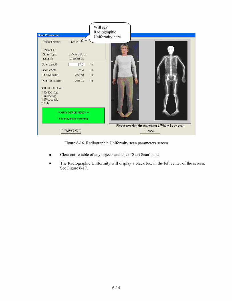
6-14
Figure 6-16. Radiographic Uniformity scan parameters screen
Clear entire table of any objects and click ‘Start Scan’; and
The Radiographic Uniformity will display a black box in the left center of the screen. See Figure 6-17.
Will say Radiographic Uniformity here.

6-15
Figure 6-17. Radiographic Uniformity test
A program will automatically analyze the airscan.
6.2.3.1 Finding the Global Standard Deviation (SD) for the Radiographic Uniformity Test (Airscan)
In the QDR main menu, select ‘Utilities’ then ‘Service Utilities’ from the drop-down box and then ‘Table Top Radiographic Uniformity’ from the second drop-down box. See Figure 6-18.

6-16
Figure 6-18. Selecting Radiographic Uniformity for SD

6-17
Select or highlight the Radiographic Uniformity with the correct scan date (date of QC Test) See Figure 6-19.
Figure 6-19. Selecting Radiographic Uniformity for SD results
There are two SD’s, a High Air and a Low Air. See Figures 6-20 and 6-21. Select
from the tabs at the top of the window. Enter both numbers in ISIS.

6-18
Figure 6-20. High Air global stats SD
Figure 6-21. Low Air global stats SD

6-19
6.2.3.2 Procedure if Standard Deviation (SD) is Greater Than 2.0
Report this to the chief technologist AND the MEC manager.
**Chief Technologist and MEC Manager:
Check the results of the air scan and confirm that the scan procedure was completed correctly;
Perform a second scan and note the results. If the Standard Deviation is still >2.0, call the home office to report the results of the air scan. (See laminated instruction sheets in the DXA room for the names and numbers of the people to contact);
If you are unable to reach anyone at the home office, contact Hologic; and
Continue doing DXA scans until further notification from the home office.
6.2.4 Slim-line Whole Body Phantom
Lift the phantom components on and off the table one at a time;
Press the center table button to center the laser. Use the laser to assist in centering the phantom on the table;
Place the bottom layer (base) on the scanner table. (The bottom layer consists of a thin, gray PVC sheet bonded to the largest high density polyethylene (HDPE) piece.) Orient the sheet with the gray PVC on the bottom and the end marked “Head End” at the head end of the table;
Place the second large white plastic piece (with beveled edges) on top of the base, using the locating pins as a guide if necessary. The second piece should be placed such that the beveled edge is in contact with the base layer, like a pyramid;
Place the medium-sized white plastic piece on the phantom;
Add the second medium-sized white plastic piece (with the beveled edges), again forming a pyramid;
Place the smallest white plastic piece on the phantom;
Add on the smallest white plastic piece (with the beveled edges) to complete the pyramid;

6-20
Secure the stack with the two locating pins; and
The final assembly will form a pyramid. (See Figure 6-22.) It is important that the phantom is placed in exactly the same configuration every time it is scanned.
Figure 6-22. Slim-line whole body phantom fully assembled
6.2.4.1 Phantom Positioning
The phantom should be centered top to bottom and side to side on the table. Use the laser to assist in centering the phantom.
6.2.4.2 Scanning the Slim-Line Whole Body Phantom (Days 1, 3, 5)
Confirm that the phantom is centered, parallel with the long axis of the table, and is correctly oriented with respect to the head of the table;
Confirm all artifacts are removed from the scanner table surface;
Select ‘Perform Exam’ from the QDR Main Menu. See Figure 6-1; and
Choose Slim-Line WB Phantom #XXXX (XXXX is 1013 on MEC 1, 1021 on MEC 2, or 1022 on MEC 3) from the list or begin typing Slim… in the white text box next to Patient Name and the name will highlight in the list. See Figure 6-23. Click ‘OK.’

6-21
Figure 6-23. Selecting Slim-Line WB Phantom scan
Type in initials in the white text box next to the word Operator (See Figure 6-24.) and
Click ‘OK.’
Figure 6-24. Operator box for initials

6-22
CONFIRM that ‘Slim-Line WB Phantom #XXXX’ is in the Patient Field.
Select ‘Whole Body’ in the Scan Selection Screen. Figure 6-25. Click ‘Next>>.’
Figure 6-25. Selecting Whole Body in the select scan type screen
The Scan Parameters Screen is displayed. Click ‘Start Scan.’ Figure 6-26.
Figure 6-26. Slim-Line scan parameters screen

6-23
The machine will scan the phantom;
As the scan is completing, carefully inspect the image to ensure that the phantom was centered, parallel with the long axis of the scanner table and the phantom’s head appears at the top of the image; and
If the scan is not satisfactory, reposition the phantom again, carefully following the instructions above.
6.2.4.3 Scanning the Slim-line Whole Body Phantom for Start of Stand
Confirm that the phantom is centered, parallel with the long axis of the table, and is correctly oriented with respect to the head of the table;
Confirm all artifacts are removed from the scanner table surface;
Follow procedures from Section 6.2.4.2 for scanning the first Slim-line Whole Body Phantom scan; and
If the scan is satisfactory, slide the phantom down the table and then recenter. Scan 4 more times with repositioning between each scan, checking that each scan is satisfactory.
NOTE: Autoscan cannot be used for the Slim-line Whole Body Phantom.

6-24
6.2.5 Hologic Femur/Hip Phantom (Weekly Scan)
Center the table. When the table motion is complete, position the Hologic Femur/Hip Phantom on the table and align laser cross with mark on phantom.
Select ‘Perform Exam’ from the QDR Main Menu. See Figure 6-1 shown earlier.
Choose/highlight ‘Hologic Femur/Hip Phantom #WHF–XXXX’ (XXXX is 0013 on MEC 1, 0021 on MEC 2, or 0018 on MEC 3) from the list. See Figure 6-27. Click ‘OK.’
Figure 6-27. Selecting Hologic Femur/Hip Phantom from patient menu

6-25
Type in initials in the white text box next to the word Operator (See Figure 6-28.) and Click ‘OK.’
Figure 6-28. Operator box for initials
CONFIRM that ‘Hologic Femur/Hip Phantom #WHF- XXXX’ is in the Patient Field.
Select ‘Right Hip’ in the Scan Selection Screen. Figure 6-29.
Figure 6-29. Selecting Right Hip in the scan selection screen

6-26
Confirm ‘Use Default Scan Mode’ is checked. Click ‘Next>>’; and
The Scan Parameters screen is displayed. See Figure 6-30.
Figure 6-30. Hologic Femur/Hip Phantom scan parameters screen

6-27
If phantom is positioned correctly, click ‘Start Scan’; and
The machine will scan the phantom. See Figure 6-31.
Figure 6-31. Machine scanning Femur/Hip phantom
As the scan is completing, carefully inspect the image to ensure that the phantom was
correctly positioned;
If the scan is not satisfactory, click ‘Reposition Scan,’ use the scrollbars or mouse to position the phantom correctly in the black box, and click ‘Restart Scan’; and
Upon successful completion of the scan, select ‘Exit Exam’ to return to the QDR Main menu, or to perform a different scan. Select ‘New Scan’ if performing another Femur/Hip Phantom scan. See Figure 6-32.

6-28
Figure 6-32. Exit exam/new scan window box
6.2.5.1 Hologic Femur/Hip Phantom Start of Stand using Auto Scan
Follow procedures from Section 6.2.5 for positioning and scanning the Hologic Femur/Hip Phantom #WHF- XXXX;
A total of five scans should be completed for start of stand; and
To use the Auto Scan feature, follow procedures in Section 6.3.
6-29
6.2.6 Circulating HASP (HSP Q-96)
NOTE: This phantom is a different phantom from the one used for daily scans. Do not use the regular spine phantom that is used for daily QC scans;
Center the table. When the table motion is complete, position the Hologic Circulating Spine Phantom on the table at the position indicated by the laser cross;
The positioning star should be pointing to the foot of the table (your left as you face the table);
The laser cross should be centered on the positioning star;
The laser line should be centered on the line between the numbers 9 and 6;
On the QDR main menu screen, click ‘Utilities’ at the top of the screen;
From the drop-down menu, select ‘Service Utilities’ and then ‘Auto Scan’ from the second drop-down menu. See Figure 6-35;
Choose Hologic Spine Phantom Q-96 from the list or begin typing Hologic Spine… in the white text box next to Patient Name and the name will highlight in the list. Click ‘OK’;
Type in initials in the white text box next to the word Operator. Click ‘OK’;
CONFIRM that ‘Hologic Spine Phantom Q-96’ is in the patient field;
Select ‘AP Lumbar Spine’ in the Scan Selection screen. Figure 6-36;
In white text box to the left of ‘Number of times to run scan,’ type the number 10. See Figure 6-36;
Click ‘Next >>’;
The Scan Parameters Screen is displayed. Click ‘Start Scan’;
The machine will scan the phantom; and
A total of 10 scans should have been completed.

6-30
6.2.7 Circulating Block Phantom (Hologic Block Phantom NH #1)
Center the table. When the table motion is complete, position the Hologic circulating spine phantom on the table at the position indicated by the laser cross;
The positioning star should be pointing to the foot of the table;
The laser cross should be centered on the positioning star;
The laser line should be positioned between the numbers 1 and 2;
On the QDR main menu screen, click ‘Utilities’ at the top of the screen;
From the drop-down menu, select ‘Service Utilities’ and then ‘Auto Scan’ from the second drop-down menu. See Figure 6-35;
Choose Hologic Block Phantom NH #1 from the list or begin typing Hologic Block… in the white text box next to Patient Name and the name will highlight in the list. Click ‘OK’;
Type in initials in the white text box next to the word Operator. Click ‘OK’;
CONFIRM that ‘Hologic Block Phantom NH #1’ is in the Patient Field;
Select ‘AP Lumbar Spine’ in the Scan Selection Screen. Figure 6-36;
In white text box to the left of ‘Number of times to run scan,’ type the number 10. See Figure 6-36;
Click ‘Next >>’;
The Scan Parameters Screen is displayed. Click ‘Start Scan’;
The machine will scan the phantom; and
A total of 10 scans should have been completed.

6-31
6.2.8 Hologic Whole Body Phantom #008
6.2.8.1 Phantom Assembly
Lift the phantom components on and off the table one at a time;
Refer to the diagram to assist in positioning the phantom correctly;
Place the bottom layer (base) of the phantom on the scanner table. (The bottom layer consists of a thin gray PVC sheet attached to a large white plastic sheet that contains two plastic locating pins). Orient the serial numbers to the head end of the table;
Position the bottom layer such that the gray PVC is on the bottom (the gray PVC is in contact with the table and the two alignment holes are facing out of the plane of the table toward the ceiling);
Place the second large white plastic piece on top of the phantom base, using the alignment holes as a guide. This piece should be placed such that the beveled edge forms a 45 degree angle with the base, with the serial numbers oriented to the head of the table;
Next place the medium size white plastic pieces on the phantom, with the top medium piece forming a 45 degree angle with the bottom medium piece. Make sure the serial numbers are toward the head of the table;
Place the small white plastic pieces on top, to resemble the medium and large setup;
Insert the locating pins through the alignment holes;
The final assembly will form a pyramid (refer to the diagram, side view); and
Check that the phantom configuration is positioned exactly as outlined.
6.2.8.2 Phantom Positioning
Position the phantom in the center of the scanner table;
Put the head of the phantom at the head of the table. (The head of the phantom is the end that has the phantom serial number label attached to it);
Position the head of the phantom 24 inches from the head of the table; and
Carefully position the phantom parallel with the long axis of the table, using the table pad markings as a guide.

6-32
6.2.8.3 Scanning the Whole Body Phantom
Confirm that the phantom is centered, is parallel with the long axis of the table, and is correctly oriented with respect to the head of the table;
Confirm that all artifacts are removed from the scanner table surface;
On the QDR main menu screen, click ‘Utilities’ at the top of the screen;
From the drop-down menu, select ‘Service Utilities’ and then ‘Auto Scan’ from the second drop-down menu. See Figure 6-35;
Choose WB Phantom #008 (008 is the serial number of the Whole Body Phantom) from the list or begin typing WB… in the white text box next to patient name and the name will highlight in the list. Click ‘OK’;
Type in initials in the white text box next to the word Operator. Click ‘OK’;
CONFIRM that ‘WB Phantom #008’ is in the patient field;
Select ‘Whole Body’ in the Scan Selection screen. Figure 6-36;
In white text box to the left of ‘Number of times to run scan,’ type the number 5. See Figure 6-36. Click ‘Next >>’;
The Scan Parameters Screen is displayed. Click ‘Start Scan’;
The machine will scan the phantom.
Figure 6-33. Layout of whole body phantom – top view
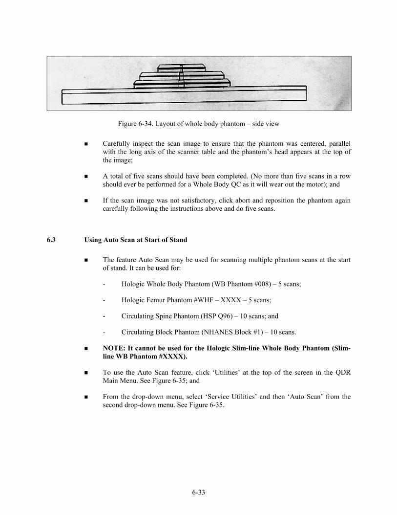
6-33
Figure 6-34. Layout of whole body phantom – side view
Carefully inspect the scan image to ensure that the phantom was centered, parallel with the long axis of the scanner table and the phantom’s head appears at the top of the image;
A total of five scans should have been completed. (No more than five scans in a row should ever be performed for a Whole Body QC as it will wear out the motor); and
If the scan image was not satisfactory, click abort and reposition the phantom again carefully following the instructions above and do five scans.
6.3 Using Auto Scan at Start of Stand
The feature Auto Scan may be used for scanning multiple phantom scans at the start of stand. It can be used for:
- Hologic Whole Body Phantom (WB Phantom #008) – 5 scans;
- Hologic Femur Phantom #WHF – XXXX – 5 scans;
- Circulating Spine Phantom (HSP Q96) – 10 scans; and
- Circulating Block Phantom (NHANES Block #1) – 10 scans.
NOTE: It cannot be used for the Hologic Slim-line Whole Body Phantom (Slim-line WB Phantom #XXXX).
To use the Auto Scan feature, click ‘Utilities’ at the top of the screen in the QDR Main Menu. See Figure 6-35; and
From the drop-down menu, select ‘Service Utilities’ and then ‘Auto Scan’ from the second drop-down menu. See Figure 6-35.
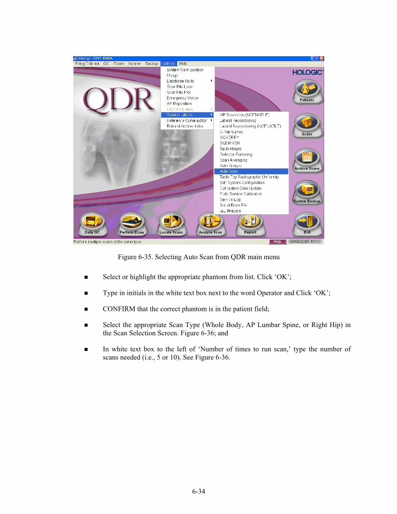
6-34
Figure 6-35. Selecting Auto Scan from QDR main menu
Select or highlight the appropriate phantom from list. Click ‘OK’;
Type in initials in the white text box next to the word Operator and Click ‘OK’;
CONFIRM that the correct phantom is in the patient field;
Select the appropriate Scan Type (Whole Body, AP Lumbar Spine, or Right Hip) in the Scan Selection Screen. Figure 6-36; and
In white text box to the left of ‘Number of times to run scan,’ type the number of scans needed (i.e., 5 or 10). See Figure 6-36.

6-35
Figure 6-36. Number of times to run scan
Click ‘Next >>’;
The Scan Parameters screen is displayed. Click ‘Start Scan’;
The machine will continue to scan the phantom the number of times indicated;
As the scan is completing, carefully inspect the image is satisfactory;
If the scan is not satisfactory, stop the Auto Scan, reposition the phantom again, carefully following the instructions above; and
NOTE: No more than 5 scans in a row should ever be performed for a Whole Body QC as it will wear out the motor.
6-36
6.4 QC Scan Checklists
The QC Scan checklists were developed to ensure that all QC Scans are completed as outlined in the protocol. There are two forms: one is used for all daily, 3 times/week, and weekly QC scans; the other is used for all Start of Stand QC scans. See Appendixes E and F for sample forms.
6.4.1 Instructions for Completing Weekly QC Scan Checklist
The checklist should be filled out on each day of the workweek by the health technologist who is responsible for completing the QC scans that week;
As scans are completed each day, check the appropriate boxes; and
During the week, keep the checklist in the Body Composition Procedures manual. At the end of each week, file the completed form in the ‘Weekly QC Scans Checklist’ section in the back of the manual, behind the previous week’s form.
6.4.2 Instructions for Completing Start of Stand QC Scan Checklist
The checklist should be filled out at the start of the stand by the health technologist who is responsible for completing the start of stand scans;
As each scan is completed, check the appropriate box; and
File the completed form in the ‘Start of Stand QC Scans Checklist’ section in the back of the manual, behind the form from the previous stand.
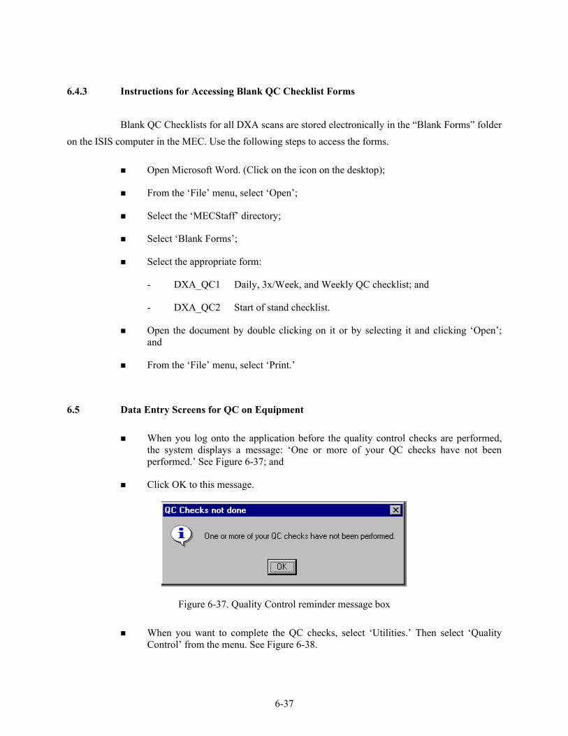
6-37
6.4.3 Instructions for Accessing Blank QC Checklist Forms
Blank QC Checklists for all DXA scans are stored electronically in the “Blank Forms” folder on the ISIS computer in the MEC. Use the following steps to access the forms.
Open Microsoft Word. (Click on the icon on the desktop);
From the ‘File’ menu, select ‘Open’;
Select the ‘MECStaff’ directory;
Select ‘Blank Forms’;
Select the appropriate form:
- DXA_QC1 Daily, 3x/Week, and Weekly QC checklist; and
- DXA_QC2 Start of stand checklist.
Open the document by double clicking on it or by selecting it and clicking ‘Open’; and
From the ‘File’ menu, select ‘Print.’
6.5 Data Entry Screens for QC on Equipment
When you log onto the application before the quality control checks are performed, the system displays a message: ‘One or more of your QC checks have not been performed.’ See Figure 6-37; and
Click OK to this message.
Figure 6-37. Quality Control reminder message box
When you want to complete the QC checks, select ‘Utilities.’ Then select ‘Quality
Control’ from the menu. See Figure 6-38.

6-38
Figure 6-38. Utilities menu to select quality control
Clicking on the QC icon from the Toolbar can also access the QC screens; and
When QC is selected from the Utilities menu, the User ID entry box will be displayed. See Figure 6-39.
Figure 6-39. Quality Control log-on
Each technologist will have a personal ID. This ID will be used to identify the person
who completed the QC checks for this time period;
Enter your User ID and click OK; and
If you do not want to do the QC checks at this time, click Cancel.

6-39
6.5.1 Daily QC Checks
The Daily QC check data entry screen is shown in Figures 6-40.
Figure 6-40. Quality Control daily checks
On the QC screens, check ‘Done’ for the listed items when that item has been
completed;
You are not required to enter anything in the ‘Result’ or ‘Comment’ fields unless there is a problem;
The ‘Result’ field is used to enter values for selected QC items if required;
The ‘Comments’ field is used to enter information about problems encountered with the QC item check;
Use the scroll bar to move to the remaining items; and
When you are finished with the daily item checks, click OK to close the QC box.
6.5.2 Weekly QC Checks
The Weekly QC Check Data Entry screen is shown in Figures 6-41 and 6-42; and
Complete all the daily checks.

6-40
Figure 6-41. Quality Control weekly checks (1)
Figure 6-42. Quality Control weekly checks (2)
Check ‘Done’ for each item on the weekly checks when complete;
Use the Scroll down bar on the right of the screen to get to the remaining items; and
If you notice a problem with any of the items on the check list, make a note of this in the comment box and report it to the MEC manager.
6.5.3 Start of Stand QC Checks
The Start of Stand QC Check data entry screen is shown in Figures 6-43 and 6-44.

6-41
Figure 6-43. Quality Control stand checks (1)
Figure 6-44. Quality Control stand checks (2)
Complete all ‘Start of Stand’ checks;
‘Start of Stand’ checks include all daily and weekly checks;
When the ‘Start of Stand’ checks are complete, click OK to close the QC checks;
Complete the remaining ‘Start of Stand’ checks; and
When you have completed all checks, click OK to close the QC box.
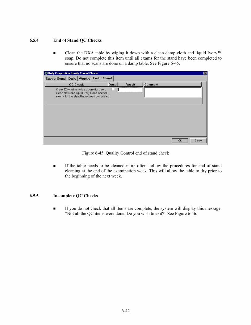
6-42
6.5.4 End of Stand QC Checks
Clean the DXA table by wiping it down with a clean damp cloth and liquid Ivory™ soap. Do not complete this item until all exams for the stand have been completed to ensure that no scans are done on a damp table. See Figure 6-45.
Figure 6-45. Quality Control end of stand check
If the table needs to be cleaned more often, follow the procedures for end of stand
cleaning at the end of the examination week. This will allow the table to dry prior to the beginning of the next week.
6.5.5 Incomplete QC Checks
If you do not check that all items are complete, the system will display this message: “Not all the QC items were done. Do you wish to exit?” See Figure 6-46.

6-43
Figure 6-46. Quality Control incomplete entry
If you want to complete the items before exiting, click “No” to this message and
complete the items;
If you wish to exit without completing all the QC checks, click “Yes” to this message; and
If all QC items were not complete, the system will remind you each time you log on that the QC checks are not complete.

APPENDIX A
BODY COMPOSITION (DXA) SCRIPTS

A-1
APPENDIX A
BODY COMPOSITION (DXA) SCRIPTS
Introduction to Component (Suggested Script) English Spanish
In this room, I’m going to take three scans of your body with this machine. These scans can tell us how strong your bones are and how much fat you have. I will explain each exam in more detail as I go along.
En este cuarto, vamos a hacer dos tipos de exámenes. Un examen nos puede decir qué tan fuertes están sus huesos y cuánta grasa tiene usted. El otro examen mide la cantidad de agua en su cuerpo. Explicaré cada examen en más detalle mientras que lo esté haciendo.
General Explanation of DXA Scans English Spanish
It will take about 3 minutes to position you correctly for each scan and another few minutes to take the scans. The scan of your hip and spine will tell us how strong your bones are compared to other people like you, and the scan of your whole body will tell us how much body fat you have. I will explain each scan in more detail as I position you for the scan. I am going to ask you a few questions before I start the exam (safety exclusion questions are asked). Please lie down on the table now and get as comfortable as possible. During the scans be as still as possible and do not talk.
En el primer examen, voy a tomar tres escáneres de su cuerpo con esta máquina. Tomará más o menos 3 minutos ponerle en la posición correcta para cada escáner y otros pocos minutos para tomar los escáneres. El escáner de su cadera y de su columna nos dirá qué tan fuertes están sus huesos comparados con los de otras personas como usted, y el escáner de todo su cuerpo nos indicará cuánta grasa tiene usted en el cuerpo. Le explicaré cada escáner en más detalle mientras que le posicione para el escáner. Le voy a hacer algunas preguntas antes de empezar el examen (safety exclusion questions are asked). Por favor acuéstese sobre la mesa ahora y póngase lo más cómodo(a) posible. Durante los escáneres quédese lo más quieto(a) posible y no hable.
General Explanation of Whole Body DXA Scan English Spanish
The first scan we will do is the whole body scan. For this scan, please lie still on the table with your arms by your sides. I’m going to position your arms and feet correctly for the scan and then wrap these Velcro straps loosely around your feet to hold them in place. This scan will take about 3 minutes to complete. As the machine scans your body, the table will move up and down and back and forth. This overhead arm will also be moving.
El primer escáner que haremos es un escáner de todo el cuerpo. Para este escáner, por favor acuéstese sobre la mesa sin moverse con los brazos a los lados. Voy a ponerle los brazos y los pies correctamente para el escáner y después le pondré estas cintas “Velcro” no muy apretadas alrededor de los pies para mantenerlos en su lugar. Este escáner tomará más o menos 3 minutos para completarse. Mientras que la máquina toma el escáner de su cuerpo, la mesa se moverá hacia arriba y hacia abajo, y hacia adelante y hacia atrás. Este brazo de arriba también se estará moviendo.
(Revised April 2005)

A-2
General Explanation of AP Spine Scan
English Spanish For the spine scan, you will also lie flat on the table, but I’m going to bend your legs at a 90 degree angle at the hip and knee by placing them on this large soft cube-shaped pillow. This scan will take only 30 seconds. You will not feel anything during this scan.
Para el escáner de la columna vertebral, usted también tendrá que recostarse extendido sobre la mesa, pero yo le voy a doblar las piernas en un ángulo de 90 grados en la cadera y las rodillas poniéndolas en esta almohada grande y suave en forma de cubo. Este escáner tomará solamente 30 segundos. Usted no sentirá nada durante este escáner.
General Explanation of Femur Scan English Spanish
The next scan will be of your hip. For this scan, please continue to lie still with your legs flat against the table. I will rotate your left leg inward slightly and then keep it in place using this foot brace. It will take about 30 seconds to complete this scan. You will not feel anything during the scanning.
El siguiente escáner será para su cadera. Para este escáner, por favor continúe recostado sin moverse con las piernas extendidas sobre la mesa. Voy a moverle la pierna izquierda un poco hacia adentro y después la mantendré en esa posición usando estas bandas para los pies. Tomará más o menos 30 segundos para completar este escáner. Usted no sentirá nada durante este escáner.
Consent for Second Exam English Spanish
The image quality of your whole body scan is not adequate for reporting your bone density results. I see from your scan that [fill in the problem observed]. With your permission, I would like to repeat the scan to improve the image quality. The amount of radiation from this scan is about 1 millirem, or the amount you would receive for 2 hours on a coast-to-coast airplane flight. This scan is voluntary and there is no penalty for refusing. Do I have your permission to repeat the scan?
La calidad de la imagen del escáner de todo su cuerpo no es adecuada para informar el resultado de la densidad de los huesos. Veo por su escáner que [fill in the problem observed]. Con su autorización, quisiera repetir el escáner para mejorar la calidad de la imagen. La cantidad de radiación de este escáner es 1 milirem, o sea, la cantidad que usted recibiría en un vuelo en avión de dos horas de costa a costa. Este escáner es voluntario y no hay consecuencias negativas por rehusar. ¿Me da su autorización para repetir el escáner?
(Revised April 2005)

APPENDIX B
SAFETY/EXCLUSION QUESTIONS (SPANISH TRANSLATION)

B-1
APPENDIX B
SAFETY/EXCLUSION QUESTIONS (SPANISH TRANSLATION)
Safety Exclusion Questions (Screen 1)
English Spanish Do you have any amputations of your legs and feet other than toes?
¿Tiene alguna amputación de las piernas y pies que no sean los dedos de los pies?
Where is the amputation?
¿Se refiere a la cadera derecha, izquierda o las dos caderas?
How much do you weigh without clothes or shoes? ¿Cuánto pesa sin ropa o zapatos? Do you have a pacemaker or automatic defibrillator?
¿Tiene un marcapaso o desfibrilador automático?
Are you currently pregnant?
¿Está usted actualmente embarazada?
How many weeks?
¿Cuántas semanas?
Safety Exclusion Questions (Screen 2) English Spanish
Has SP removed all jewelry, eyeglasses, hair ornaments, and other objects from the hair and body?
This is an observation, not a question.
Does the SP have any amputations other than fingers or toes?
This is an observation, not a question.
Do you have any artificial joints, pins, plates, shrapnel, or other types of metal objects in your body?
¿Tienen usted alguna (articulación/coyuntura) artificial, un clavo ortopédico, una placa artificial u otro tipo de objetos de metal en el cuerpo?
Do you have any coronary stents or metal suture material in your heart?
¿Tiene usted alguna endoprótesis vascular también conocidas como 'stents' o algún material de sutura metálico en el corazón?
Are you using an insulin pump or have insulin lines now?
¿Está usando una bomba de insulina o tiene sondas de insulina ahora?
Do you have an ostomy, such as an ileostomy or colostomy?
¿Tiene usted una ostomía, o sea una pequeña abertura, tal como una ileostomía, abertura en el intestino delgado, o colostomía, abertura en el colon?

B-2
Safety Exclusion Questions (Screen 2, continued)
English Spanish Are you wearing a hearing aid now? ¿Está usando audífono ahora?
Have you had an X-ray with contrast material such as barium in the last 7 days?
¿Le han tomado una radiografía con material de contraste tal como barium en los últimos 7 días?
Have you had any nuclear medicine studies in the past 3 days?
¿Le han hecho algún estudio en que usaran medicina nuclear en los últimos 3 días?
Have you ever fractured your hip, had a hip replacement, or do you have a pin in your hip?
¿Se ha fracturado alguna vez la cadera, le han hecho un reemplazo de la cadera o tiene un clavo ortopédico en la cadera?
Is it your right hip, left hip, or both?
¿Se refiere a la cadera derecha, izquierda o las dos caderas?
Do you have a lumbar spine fusion?
¿Tiene usted una fusión lumbar, o sea, una unión de huesos, de la columna vertebral?

APPENDIX C
SET-UP AND TEAR-DOWN PROCEDURES FOR BODY COMPOSITION ROOM
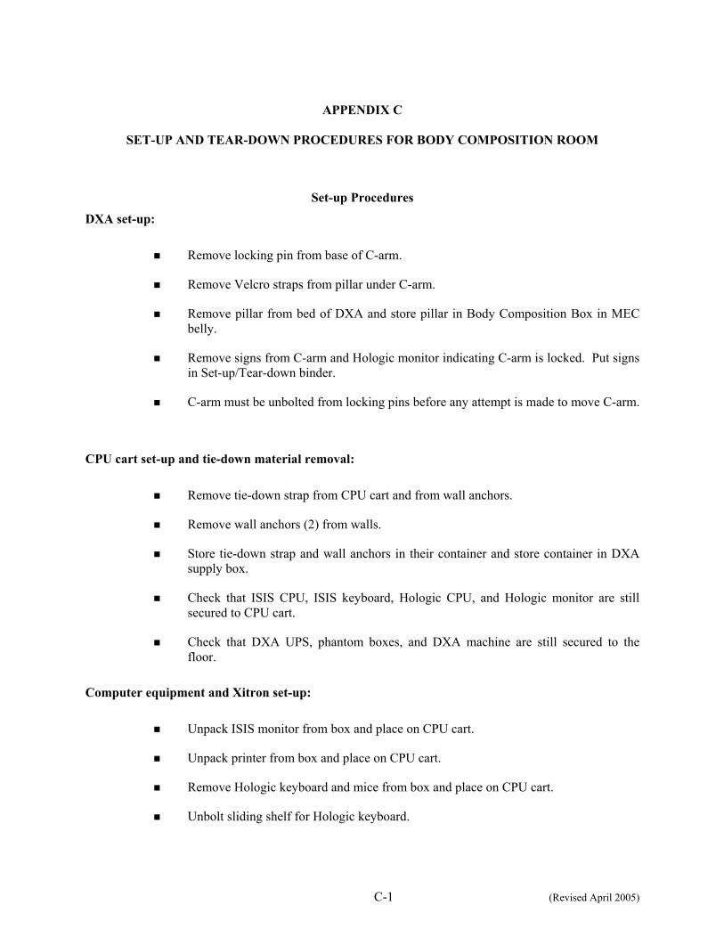
C-1 (Revised April 2005)
APPENDIX C
SET-UP AND TEAR-DOWN PROCEDURES FOR BODY COMPOSITION ROOM
Set-up Procedures
DXA set-up:
Remove locking pin from base of C-arm.
Remove Velcro straps from pillar under C-arm.
Remove pillar from bed of DXA and store pillar in Body Composition Box in MEC belly.
Remove signs from C-arm and Hologic monitor indicating C-arm is locked. Put signs in Set-up/Tear-down binder.
C-arm must be unbolted from locking pins before any attempt is made to move C-arm.
CPU cart set-up and tie-down material removal:
Remove tie-down strap from CPU cart and from wall anchors.
Remove wall anchors (2) from walls.
Store tie-down strap and wall anchors in their container and store container in DXA supply box.
Check that ISIS CPU, ISIS keyboard, Hologic CPU, and Hologic monitor are still secured to CPU cart.
Check that DXA UPS, phantom boxes, and DXA machine are still secured to the floor.
Computer equipment and Xitron set-up:
Unpack ISIS monitor from box and place on CPU cart.
Unpack printer from box and place on CPU cart.
Remove Hologic keyboard and mice from box and place on CPU cart.
Unbolt sliding shelf for Hologic keyboard.

C-2 (Revised April 2005)
Connect all computer equipment on CPU cart to CPU.
Store boxes for computer equipment (should be labeled DXA) in MEC belly during a stand.
Supply set-up:
Connect telephone receiver to telephone and plug telephone into wall jack.
Unpack binders for DXA room and place on basket in grid.
Unpack grid baskets from box and hang on wall grid.
Restock containers in grid baskets where needed.
Place new Velcro foot strap in grid basket; discard used strap.
Restore trash can and chair to upright positions.
Store DXA supply box in MEC belly during a stand.
Chief Technologist:
Make a final check on room set-up.
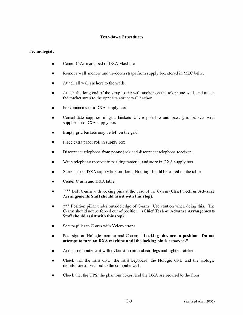
C-3 (Revised April 2005)
Tear-down Procedures
Technologist:
Center C-Arm and bed of DXA Machine
Remove wall anchors and tie-down straps from supply box stored in MEC belly.
Attach all wall anchors to the walls.
Attach the long end of the strap to the wall anchor on the telephone wall, and attach the ratchet strap to the opposite corner wall anchor.
Pack manuals into DXA supply box.
Consolidate supplies in grid baskets where possible and pack grid baskets with supplies into DXA supply box.
Empty grid baskets may be left on the grid.
Place extra paper roll in supply box.
Disconnect telephone from phone jack and disconnect telephone receiver.
Wrap telephone receiver in packing material and store in DXA supply box.
Store packed DXA supply box on floor. Nothing should be stored on the table.
Center C-arm and DXA table.
*** Bolt C-arm with locking pins at the base of the C-arm (Chief Tech or Advance Arrangements Staff should assist with this step).
*** Position pillar under outside edge of C-arm. Use caution when doing this. The C-arm should not be forced out of position. (Chief Tech or Advance Arrangements Staff should assist with this step).
Secure pillar to C-arm with Velcro straps.
Post sign on Hologic monitor and C-arm: “Locking pins are in position. Do not attempt to turn on DXA machine until the locking pin is removed.”
Anchor computer cart with nylon strap around cart legs and tighten ratchet.
Check that the ISIS CPU, the ISIS keyboard, the Hologic CPU and the Hologic monitor are all secured to the computer cart.
Check that the UPS, the phantom boxes, and the DXA are secured to the floor.

C-4 (Revised April 2005)
Turn room chair upside down.
Turn trash can on its side.
Chief Technologist:
Make final check on pack-up of the room with the technologist.
Advance Arrangements Staff:
Disconnect ISIS monitor and printer from CPU.
Remove ISIS monitor from cart and place in box with packing material.
Remove printer from cart and place in box with packing material.
Disconnect both mice and Hologic keyboard from CPU.
Pack the mice and the Hologic keyboard into a box with packing material.
Place all packed boxes on the floor. Nothing should be stored on the bed of the DXA.
Bolt sliding shelf for Hologic keyboard with sliding pin.
Unplug all electrical equipment.

APPENDIX D
DXA BONE DENSITOMETER REPORT

D-1
APPENDIX D
USE ONE FORM FOR EACH SCANNER IN THIS STUDY THIS FORM ONLY PERTAINS TO STUDIES IN WHICH DXA DATA ARE SENT TO USCF. HOLOGIC SCANNER OPERATORS SHOULD SEND THIS FORM ALONG WITH QC ARCHIVE OR dBARCHIVE DISKETTE(S) AND BMD, BMC, AND AREA PLOTS FOR THE MOST RECENT SIX MONTHS.
DXA Bone Densitometer Report NHANES IV MEC number (1, 2, or 3) _________________ Scanner Serial Number ____________ Hologic Spine Phantom Number __________________ 1) Has a new / different scanner been used for any study patients? Yes No If yes, circle Was scanner change approved in advance by UCSF? Yes No By Whom? ___________ 2) Has there been any software changes? Yes No If yes, indicate: ________ Old software version: ________ New software version: ________ Date installed: ___________ Was software change approved in advance by UCSF? Yes No By Whom? _______. 3) Were there any technologist changes? Yes No If yes:
Technologist
Added / Departed
Date of Change
Date of Manufacturer’s Training
4) Were there any maintenance/recalibration/repair problems? Yes No If yes, indicate:
Service Performed Date of Service 5) Additional comments (Use reverse side if necessary): Main Technologist: _____________________________ Date: ____________ Telephone: __________ Please make copies of this blank form. Compete this form each reporting period and send the original to the UCSF Quality Assurance Center and keep a copy for your records.

D-2
DXA Bone Densitometer Service Report
When the Hologic densitometer is serviced or repaired:
The chief technologist will complete a 'DXA Bone Densitometer Report'.
Fax a copy of the report to the home office. See laminated cards in the DXA room for names and fax numbers. The home office will send this to the Quality Control Reading Laboratory.
Fax a copy of the service report completed by the service engineer when the repair or service was made to the home office and to the reading laboratory.
Put a copy of the service engineer's report and a copy of the DXA Bone Densitometer in the service report binder kept in the DXA room.

APPENDIX E
START OF STAND QC SCAN CHECKLIST

DXA-QC1
1
E-1
APPENDIX E Start of Stand QC Scan Checklist
Stand#:_______ Tech ID#:______ Scale Check [(your wt + dumbbell) – your wt]:______
Type of Scan
Scan 1
Spine Phantom
Step Phantom
Air Scan Global Stats SD= ______
Scan 2 Scan 3 Scan 4 Scan 5
Hologic Slim-line Whole Body Phantom (Slim-line WB Phantom #XXXX)
Hologic Femur / Hip Phantom (#WHF- XXXX)
Hologic Whole Body Phantom (WB Phantom #008)
Scan 6 Scan 7 Scan 8 Scan 9 Scan 10
Circulating Spine Phantom (HSP Q96)
Circulating Block Phantom (NHANES Block #1)

APPENDIX F
WEEKLY QC SCAN CHECKLIST

DXA-QC2
F-1
APPENDIX F
WEEKLY QC SCAN CHECKLIST
Week of: ___________________ Tech ID#:____________________ Please note: For Day 1 of the first week of each stand, it is not necessary to repeat scans that were done as part of the Start of Stand QC.
Daily:
Day 1 Day 2 Day 3 Day 4 Day 5 Day 6 (if applicable)
Type of Scan
Scan 1 Scan 1 Scan 1 Scan 1 Scan 1 Scan 1
Spine Phantom (HASP)
Slim-line Whole Body Phantom
Hologic Femur/Hip Phantom
Step Phantom (HASP)
WB QC Air Scan Global Stats SD=_____

APPENDIX G
PROCEDURE FOR SECURING THE QDR 4500A FOR TRAVEL

G-1
APPENDIX G
PROCEDURE FOR SECURING THE QDR 4500A FOR TRAVEL
POSITION TABLE & NORMAL SHUTDOWN CHIEF TECHNOLOGIST
Press 'Center Table' switch on the Control Panel to position the C-arm and table in the middle of its range.
Press and hold ‘Table In’ switch on the Control Panel until the table is all the way back.
Complete the normal shutdown procedures.
Press Shutdown.
When prompted, turn the X-ray Enable key off and put the key in the Spine Phantom box.
Turn the Computer Power switch off (the small button on the right side of the CPU). Do not press the button on the front of the CPU.
Turn the Instrument Power Switch to the OFF position (O).
Switch off the QDR 4500 Main Power Switch (located on back panel at the bottom of panel).
TURN OFF UPS ADVANCE TEAM
Switch the UPS STOP/RUN switch to STOP.
Switch off the UPS main breaker.
INSTALL C-ARM STABILIZER CHIEF TECHNOLOGIST/ADVANCE TEAM
Carefully complete the following steps. The stabilizer fits snugly between the C-arm and the table but it should not be forced.
Place the notched end of the Stabilizer on the bottom of the C-arm (tank end) and pivot the top towards the top of the C-arm.
Position the Stabilizer so that the top, and bottom, foam pads are wedged between the top of the tank cover and the bottom of the C-arm.
The C-arm must be vertical.

G-2
Secure Stabilizer by clamping the Velcro strap tightly around the top of the C-arm and fasten it to the Stabilizer pad.
SECURE C-ARM ROTATION LOCK CHIEF TECHNOLOGIST/ADVANCE TEAM
The C-arm Rotation Lock is located on the bottom left side of the C-arm (facing the scanner), behind the black shock absorber.
Turn the handle of the lock until the plunger releases and locks into place.
The Carriage Lock is located on the lower left side of the carriage.
Turn the handle until the plunger releases and locks into place.
Put pink neon signs on C-arm and over Hologic Computer screens that indicate that the locking pins are in position.
APPENDIX H
PROCEDURE FOR SETTING UP QDR 4500A FOR OPERATIONS

H-1
APPENDIX H
PROCEDURE FOR SETTING UP QDR 4500A FOR OPERATIONS
UNLOCK CARRIAGE & ROTATION LOCKS: ADVANCE TEAM /CHIEF TECH
Unlock the Carriage Lock
Unlock the C- arm rotation Lock.
Remove the pink neon signs from the C-Arm and Hologic computer screen and return to Body Composition Manual
REMOVE C- ARM STABILIZER CHIEF TECHNOLOGIST/ADVANCE TEAM
Remove the Velcro strap from the Stabilizer
Gently remove the Stabilizer from its position.
The Stabilizer is stored in the black belly box during the Stand.
POWER UP THE QDR 4500 SYSTEM ADVANCE TEAM
Note: The QDR 4500 X-ray Bone Densitometer System should only be shut down when necessary, primarily during road travel. Other than during road travel, the system should remain powered whenever possible, to avoid warm-up delays. Failure to follow this procedure may cause the UPS batteries to discharge and require significant recharge time.
Verify that the QDR 4500 main breaker is OFF, the UPS main breaker is OFF and the UPS Stop/RUN Switch is in the STOP position.
Plug in the QDR 4500 Power Module into one of the UPS outlets.
Plug in the UPS into a live power outlet (shore power or motor generator).
If running on motor generator and generator is off, start the motor generator. If running on shore power, verify that the shore power link is ON.
Switch on the UPS main breaker and wait 30 seconds. Verify that the AC line light on the UPS is lit.

H-2
Switch the UPS STOP/RUN switch to RUN and wait for the end of the second long beep. Verify that the INVERTER light on the UPS is lit.
If the UPS batteries are discharged, wait until the batteries are charged. (If you switch on the QDR 4500 without waiting for the batteries to charge, you will lose power outage protection).
Turn on the QDR 4500 Power Switch (located on the BACK PANEL AT THE BOTTOM LEFT OF THE PANEL if you are facing the panel.)
POSITION TABLE AND POWER ON TECHNOLOGIST
Carefully follow the Startup Procedures (step by step) for Hologic QDR (beginning of session).
Check the Power On lamp on the Power Switch is on.
Turn the Instrument Power Switch to the ON position.
Allow 30 minutes warm-up time.
Turn the X-ray Enable key to the ON position.
Turn the Computer Power switch to the ON position. (Do not use the button on the front of the CPU.

APPENDIX I
POWER FAILURE PROCEDURES FOR DXA
I-1
APPENDIX I
POWER FAILURE PROCEDURES FOR DXA
Use the following procedures when power fails during a session or when staff members are present in the MEC.
1. During a power failure, the Uninterruptible Power System (UPS) will maintain power
for a sufficient period of time to allow for proper shutdown of the system.
2. Turn the X-RAY ENABLE KEY to the OFF position (counterclockwise). Turn the INSTRUMENT POWER and COMPUTER POWER switches to the OFF (O) position.
3. Turn the MAIN POWER SWITCH on the Power Module back panel to the OFF position. This protects the system from power surges when power is restored.
4. After power is restored, bring the MAIN POWER switch, and then the INSTRUMENT POWER switch, back to the ON position. (See Section 2.1.2 of the Body Composition manual.) Allow the system to warm up for 30 to 60 minutes.
5. Verify system performance after a power failure by performing the daily QC procedure.
If power has failed and was restored during the night or when the MEC was unattended:
1. Follow the procedures described in Section 2.1.3 of the Body Composition manual to
properly shut the system down.
2. Turn the system on as described in Section 2.1.2 of the Body Composition manual, allow it to warm up, and verify system performance by completing the daily QC procedure.