Embed Size (px)
Citation preview

[email protected] • ENGR-22_Lec-24_3D_Fundamentals-2.ppt1
Bruce Mayer, PE Engineering 22 – Engineering Design Graphics
Bruce Mayer, PELicensed Electrical & Mechanical Engineer
Engineering 22
AutoCAD AutoCAD 3D3D
FundamentaFundamentalsls

[email protected] • ENGR-22_Lec-24_3D_Fundamentals-2.ppt2
Bruce Mayer, PE Engineering 22 – Engineering Design Graphics
Learning GoalsLearning Goals
Draw Right Hand Coord System Distinguish between ACAD World
CoOrd System (WCS) and User CoOrd Systems (UCS)
In ACAD Create and Save and UCS’s Use UCS, elev, and thickness to draw
“Extruded” Shapes Use ACAD ViewPorts to Show
Orthographic Views from a 3D View

[email protected] • ENGR-22_Lec-24_3D_Fundamentals-2.ppt3
Bruce Mayer, PE Engineering 22 – Engineering Design Graphics
AutoCAD CoOrdinate SystemsAutoCAD CoOrdinate Systems
AutoCAD system maintains a 3D database
World Coordinate System X,Y as top (plan) view (civil engineering) Z axis vertical User Coordinate System (UCS) may be
aligned with features (name and save) Icon shows current coordinate system

[email protected] • ENGR-22_Lec-24_3D_Fundamentals-2.ppt4
Bruce Mayer, PE Engineering 22 – Engineering Design Graphics
RIGHT Hand CoOrd SystemsRIGHT Hand CoOrd Systems
The CoOrd TriAd is Defined by Your RIGHT Hand → Rt-Hand Rule

[email protected] • ENGR-22_Lec-24_3D_Fundamentals-2.ppt5
Bruce Mayer, PE Engineering 22 – Engineering Design Graphics
Right-Hand RuleRight-Hand Rule Thumb points in the positive x direction Index finger points in
the positive y direction Middle finger points in
the positive z direction Used to define positive rotation
• Point thumb in the positive direction along the axis which is perpendicular to the plane of rotation
• The fingers point in the direction of positive rotation

[email protected] • ENGR-22_Lec-24_3D_Fundamentals-2.ppt6
Bruce Mayer, PE Engineering 22 – Engineering Design Graphics
World Coordinate SystemWorld Coordinate System
The Default 3D Coord Base System is the World
Coordinate System, or WCS The Orientation of the
WCS relative to the Default Screen
We Can find the WCS Icon in the Lower Left

[email protected] • ENGR-22_Lec-24_3D_Fundamentals-2.ppt7
Bruce Mayer, PE Engineering 22 – Engineering Design Graphics
WCSWCS
Note that the “Z” Axis for the WCS comes OUT of the Screen
Looking “Straight Down” on the Z-axis gives us the familiar “Plan View” 2D Orthographic Drawing System
World Co-ordinate System Set to Origin - Origin is OFF screen
World Co-ordinate System Set to Origin - Icon displayed AT origin

[email protected] • ENGR-22_Lec-24_3D_Fundamentals-2.ppt8
Bruce Mayer, PE Engineering 22 – Engineering Design Graphics
View PointView Point
Can Change the “Point of View”, or Viewpoint, for the Object in 3 Ways
• WCS View Point

[email protected] • ENGR-22_Lec-24_3D_Fundamentals-2.ppt9
Bruce Mayer, PE Engineering 22 – Engineering Design Graphics
Changing ViewPointsChanging ViewPoints
By PullDown
Menu

[email protected] • ENGR-22_Lec-24_3D_Fundamentals-2.ppt10
Bruce Mayer, PE Engineering 22 – Engineering Design Graphics
The “SW” IsoMetricThe “SW” IsoMetric

[email protected] • ENGR-22_Lec-24_3D_Fundamentals-2.ppt11
Bruce Mayer, PE Engineering 22 – Engineering Design Graphics
ViewView Command Command• view brings up
ViewPoint Dialog Box

[email protected] • ENGR-22_Lec-24_3D_Fundamentals-2.ppt12
Bruce Mayer, PE Engineering 22 – Engineering Design Graphics
The ViewPoint ToolBarThe ViewPoint ToolBar Can Also Change
ViewPoint with The “View” ToolBar
To RETURN to PLAN View in the WCS Use the PullDown Menu

[email protected] • ENGR-22_Lec-24_3D_Fundamentals-2.ppt13
Bruce Mayer, PE Engineering 22 – Engineering Design Graphics
Local (User) Coord SystemsLocal (User) Coord Systems
The WCS can be MODIFIED to fit the needs of the USER For Drawing in Orientations OTHER than the Plan View
Modify the WCS to a UCS:• Define new origin (with existing axes)
• Rotate existing Coordinate System about X, Y, or Z Axis
• Define new origin and axes (3-Point option)
• NAME and SAVE the UCS

[email protected] • ENGR-22_Lec-24_3D_Fundamentals-2.ppt14
Bruce Mayer, PE Engineering 22 – Engineering Design Graphics
User (Local) CoOrd SystemsUser (Local) CoOrd SystemsWCS → (1,4,-3)UCS → (3, 3.5, 0)
UCS
WCS
(1,4,-0)
+
+
(4,1,-3)
(4,1,0)

[email protected] • ENGR-22_Lec-24_3D_Fundamentals-2.ppt15
Bruce Mayer, PE Engineering 22 – Engineering Design Graphics
Making a UCS by Command LnMaking a UCS by Command Ln Specify an Origin UCS /New
• /orthoGraphic (specify the origin relative to the current coordinate system)
Reorient the axes UCS /New• /Zaxis (choose the direction
of the Z axis)• /3point (choose the origin and the positive X and Y
direction)• /Z (specify the angle of rotation about the Z axis)
Save and Restore the UCS• UCS /Save and UCS /Restore

[email protected] • ENGR-22_Lec-24_3D_Fundamentals-2.ppt16
Bruce Mayer, PE Engineering 22 – Engineering Design Graphics
Example → Make a UCSExample → Make a UCS Make a UCS Called
“slant” using the CoOrd from 2-Slides Back
Know origin and pts in WCS space• Start w/ WCS
• Use UCS → NEW → 3Point Commands
Set Points to Define X & Y Axes
Invoke UCS/3p to Set Origin to (4,1,0)

[email protected] • ENGR-22_Lec-24_3D_Fundamentals-2.ppt17
Bruce Mayer, PE Engineering 22 – Engineering Design Graphics
Result → Make a UCSResult → Make a UCS View from WCS
Plan View Invoke UCS/3p to
Set Origin to (4,1,0)
x-Axis INTO Paper

[email protected] • ENGR-22_Lec-24_3D_Fundamentals-2.ppt18
Bruce Mayer, PE Engineering 22 – Engineering Design Graphics
Save and Use New UCSSave and Use New UCS Give the New UCS a
NAME with the Save command
Command: ucsCurrent ucs name: *NO NAME*Enter an option [New/Move/orthoGraphic/Prev/Restore/Save/Del/Apply/?/World] <World>: sEnter name to save current UCS or [?]: slant
Change to Plan View for UCS

[email protected] • ENGR-22_Lec-24_3D_Fundamentals-2.ppt19
Bruce Mayer, PE Engineering 22 – Engineering Design Graphics
Plan View in “slant” UCSPlan View in “slant” UCS Plumbing Fitting Shows Up as Edge
View → Not too interesting Lets Make “twist” UCS by
ROTATING the WCS

[email protected] • ENGR-22_Lec-24_3D_Fundamentals-2.ppt20
Bruce Mayer, PE Engineering 22 – Engineering Design Graphics
Command History for twistCommand History for twistCommand: ucsCurrent ucs name: *WORLD*Enter an option [New/Move/orthoGraphic/Prev/Restore/Save/Del/Apply/?/World] <World>: nSpecify origin of new UCS or [ZAxis/3point/OBject/Face/View/X/Y/Z] <0,0,0>: xSpecify rotation angle about X axis <90>: 41Command: UCSCurrent ucs name: *NO NAME*Enter an option [New/Move/orthoGraphic/Prev/Restore/Save/Del/Apply/?/World] <World>: nSpecify origin of new UCS or [ZAxis/3point/OBject/Face/View/X/Y/Z] <0,0,0>: ySpecify rotation angle about Y axis <90>: 67Command: ucsCurrent ucs name: *NO NAME*Enter an option [New/Move/orthoGraphic/Prev/Restore/Save/Del/Apply/?/World] <World>: nSpecify origin of new UCS or [ZAxis/3point/OBject/Face/View/X/Y/Z] <0,0,0>: zSpecify rotation angle about Z axis <90>: 13Command: ucsCurrent ucs name: *NO NAME*Enter an option [New/Move/orthoGraphic/Prev/Restore/Save/Del/Apply/?/World] <World>: sEnter name to save current UCS or [?]: twist

[email protected] • ENGR-22_Lec-24_3D_Fundamentals-2.ppt21
Bruce Mayer, PE Engineering 22 – Engineering Design Graphics
Draw Heptagon in twist UCSDraw Heptagon in twist UCS Put Dwg-Space into
Plan View for twist Draw a Heptagon in
twist-space

[email protected] • ENGR-22_Lec-24_3D_Fundamentals-2.ppt22
Bruce Mayer, PE Engineering 22 – Engineering Design Graphics
Drawing in UCSDrawing in UCS Can ONLY Draw in
the CURRENT UCS• WCS Current →
PLAN View
To Change UCS Use the Dialog Box Invoked by PullDown• Tools → Named UCS

[email protected] • ENGR-22_Lec-24_3D_Fundamentals-2.ppt23
Bruce Mayer, PE Engineering 22 – Engineering Design Graphics
Elev and ThicknessElev and Thickness
300
high
The Elev Command Can Be used to “Extrude” Basic Shapes
Demonstrate by Constructing the Object at Left

[email protected] • ENGR-22_Lec-24_3D_Fundamentals-2.ppt24
Bruce Mayer, PE Engineering 22 – Engineering Design Graphics
EX14-14 → 1EX14-14 → 1 Start new Dwg using
acadiso.dwt Locate and draw the
50x50 “bases” for the “towers”
Change to SE Isometric view
Construct the Tower Using• Elev
• Thickness
• line

[email protected] • ENGR-22_Lec-24_3D_Fundamentals-2.ppt25
Bruce Mayer, PE Engineering 22 – Engineering Design Graphics
EX14-14 → 3EX14-14 → 3Command: _-view Enter an option [?/Categorize/lAyer state/Orthographic/Delete/Restore/Save/Ucs/Window]: _seiso Regenerating model.
Command: elevSpecify new default elevation <0.0000>:
Specify new default thickness <0.0000>: 300
Command: lLINE Specify first point:Specify next point or [Undo]:Specify next point or [Undo]:Specify next point or [Close/Undo]:Specify next point or [Close/Undo]: c
Command:LINE Specify first point:Specify next point or [Undo]:Specify next point or [Undo]:Specify next point or [Close/Undo]:Specify next point or [Close/Undo]: c
Command: zZOOMSpecify corner of window, enter a scale factor (nX or nXP), or[All/Center/Dynamic/Extents/Previous/Scale/Window/Object] <real time>: eRegenerating model.

[email protected] • ENGR-22_Lec-24_3D_Fundamentals-2.ppt26
Bruce Mayer, PE Engineering 22 – Engineering Design Graphics
EX14-14 → 4EX14-14 → 4 Move UCS to Top
Corner by Picking Point w/ Mouse
Enter an option [New/Move/orthoGraphic/Prev/Restore/Save/Del/Apply/?/World] <World>: n
Specify origin of new UCS or [ZAxis/3point/OBject/Face/View/X/Y/Z] <0,0,0>:
Draw CrossBar using• Osnap
• Elev
• Thickness

[email protected] • ENGR-22_Lec-24_3D_Fundamentals-2.ppt27
Bruce Mayer, PE Engineering 22 – Engineering Design Graphics
EX14-14 → 5EX14-14 → 5
Commands to Construct CrossBarCommand: zZOOMSpecify corner of window, enter a scale factor (nX or nXP), or[All/Center/Dynamic/Extents/Previous/Scale/Window/Object] <real time>: w
Specify first corner: Specify opposite corner:Command: elevSpecify new default elevation <0.0000>:
Specify new default thickness <300.0000>: 50
Command: lLINE Specify first point:Specify next point or [Undo]:Specify next point or [Undo]:Specify next point or [Close/Undo]:Specify next point or [Close/Undo]: c
[email protected] • ENGR-22_Lec-24_3D_Fundamentals-2.ppt28
Bruce Mayer, PE Engineering 22 – Engineering Design Graphics
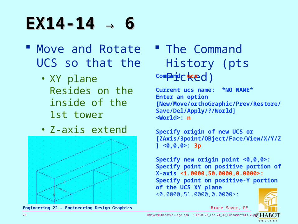
EX14-14 → 6EX14-14 → 6 Move and Rotate
UCS so that the • XY plane Resides on
the inside of the 1st tower
• Z-axis extend toward 2nd Tower
The Command History (pts Picked)
Command: ucs
Current ucs name: *NO NAME*Enter an option [New/Move/orthoGraphic/Prev/Restore/Save/Del/Apply/?/World] <World>: n
Specify origin of new UCS or [ZAxis/3point/OBject/Face/View/X/Y/Z] <0,0,0>: 3p
Specify new origin point <0,0,0>:Specify point on positive portion of X-axis <1.0000,50.0000,0.0000>:Specify point on positive-Y portion of the UCS XY plane <0.0000,51.0000,0.0000>:

[email protected] • ENGR-22_Lec-24_3D_Fundamentals-2.ppt29
Bruce Mayer, PE Engineering 22 – Engineering Design Graphics
EX14-14 → 7EX14-14 → 7 Use xline and offset
to Locate Cyl Ctr
Draw Connecting Cylinder using • elev → 0
• Thickness → 110
• Circle → Ø50

[email protected] • ENGR-22_Lec-24_3D_Fundamentals-2.ppt30
Bruce Mayer, PE Engineering 22 – Engineering Design Graphics
EX14-14 → 8EX14-14 → 8
Expand Limits, zoom → 1 to fit

[email protected] • ENGR-22_Lec-24_3D_Fundamentals-2.ppt31
Bruce Mayer, PE Engineering 22 – Engineering Design Graphics
EX14-14 → 9EX14-14 → 9
Commands to Construct OrthoViewPortsCommand: limitsReset Model space limits:Specify lower left corner or [ON/OFF] <0.0000,0.0000>:Specify upper right corner <210.0000,330.0000>: 210,360Command: zZOOMSpecify corner of window, enter a scale factor (nX or nXP), or[All/Center/Dynamic/Extents/Previous/Scale/Window/Object] <real time>: 1Command: zZOOMSpecify corner of window, enter a scale factor (nX or nXP), or[All/Center/Dynamic/Extents/Previous/Scale/Window/Object] <real time>: 1Command: -viewEnter an option [?/Categorize/lAyer state/Orthographic/Delete/Restore/Save/Ucs/Window]: oEnter an option [Top/Bottom/Front/BAck/Left/Right]<Top>: rRegenerating model.Command: zZOOMSpecify corner of window, enter a scale factor (nX or nXP), or[All/Center/Dynamic/Extents/Previous/Scale/Window/Object] <real time>: 1

[email protected] • ENGR-22_Lec-24_3D_Fundamentals-2.ppt32
Bruce Mayer, PE Engineering 22 – Engineering Design Graphics
All Done for TodayAll Done for Today
The AMEand
Bonus Tol.
3D Orbit Command

[email protected] • ENGR-22_Lec-24_3D_Fundamentals-2.ppt33
Bruce Mayer, PE Engineering 22 – Engineering Design Graphics
Bruce Mayer, PELicensed Electrical & Mechanical Engineer
Engr/Math/Physics 25
AppendiAppendixx
6972 23 xxxxf

[email protected] • ENGR-22_Lec-24_3D_Fundamentals-2.ppt34
Bruce Mayer, PE Engineering 22 – Engineering Design Graphics
Rotate Axis OnScreenRotate Axis OnScreen

[email protected] • ENGR-22_Lec-24_3D_Fundamentals-2.ppt35
Bruce Mayer, PE Engineering 22 – Engineering Design Graphics
EX14-5EX14-5

[email protected] • ENGR-22_Lec-24_3D_Fundamentals-2.ppt36
Bruce Mayer, PE Engineering 22 – Engineering Design Graphics
EX14-5 → zoom → 1EX14-5 → zoom → 1

[email protected] • ENGR-22_Lec-24_3D_Fundamentals-2.ppt37
Bruce Mayer, PE Engineering 22 – Engineering Design Graphics
EX14-5EX14-5