Embed Size (px)
Citation preview
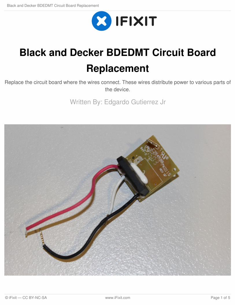
Black and Decker BDEDMT Circuit BoardReplacement
Replace the circuit board where the wires connect. These wires distribute power to various parts ofthe device.
Written By: Edgardo Gutierrez Jr
Black and Decker BDEDMT Circuit Board Replacement
© iFixit — CC BY-NC-SA www.iFixit.com Page 1 of 5
INTRODUCTION
In this guide we will show step by step to replace the main circuit board within the device. The circuitboard takes power from the chord and sends it to the trigger and motor. Any number of things couldcause the circuit board from failing such as faulty wiring, to water entering the device. This guide ispretty simple and can be done in only four major steps.
TOOLS:Tweezers (1)
64 Bit Driver Kit (1)
Black and Decker BDEDMT Circuit Board Replacement
© iFixit — CC BY-NC-SA www.iFixit.com Page 2 of 5
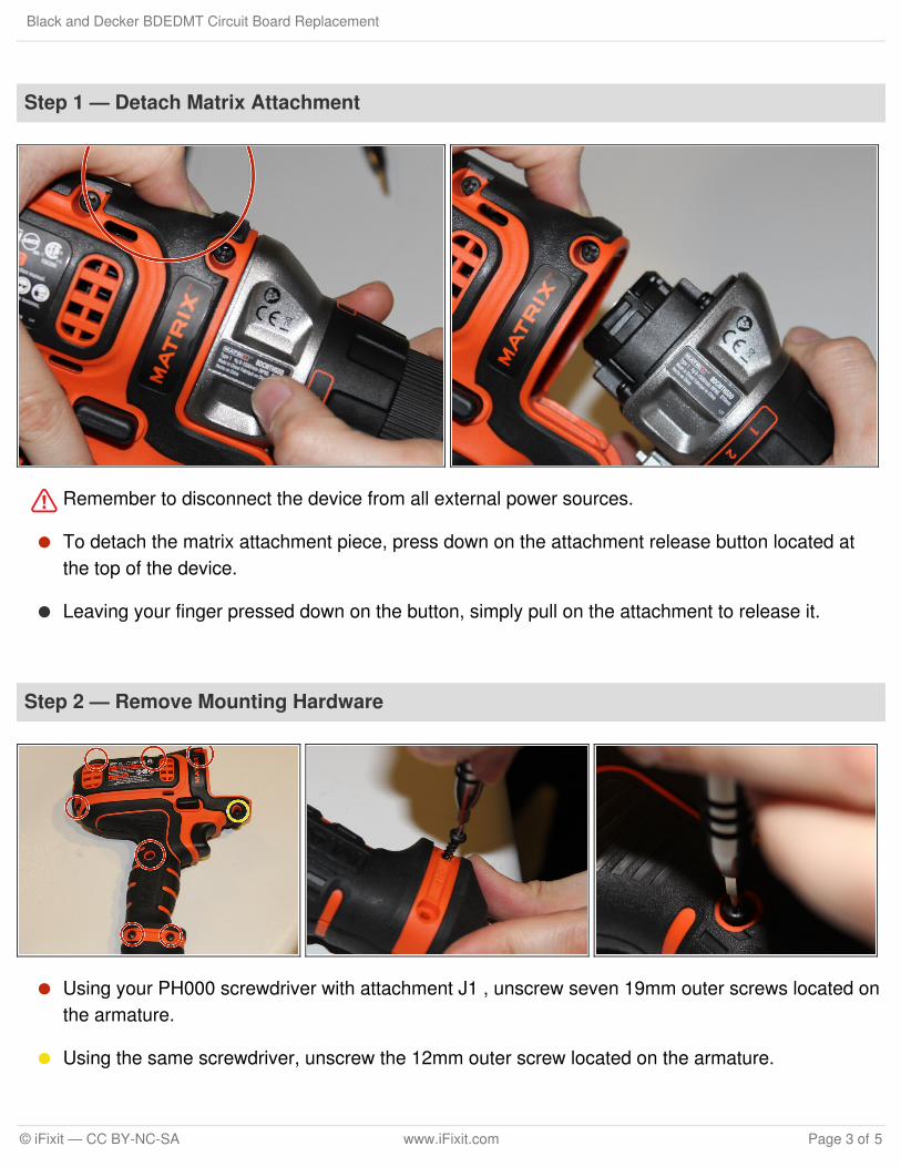
Step 1 — Detach Matrix Attachment
Remember to disconnect the device from all external power sources.
To detach the matrix attachment piece, press down on the attachment release button located atthe top of the device.
Leaving your finger pressed down on the button, simply pull on the attachment to release it.
Step 2 — Remove Mounting Hardware
Using your PH000 screwdriver with attachment J1 , unscrew seven 19mm outer screws located onthe armature.
Using the same screwdriver, unscrew the 12mm outer screw located on the armature.
Black and Decker BDEDMT Circuit Board Replacement
© iFixit — CC BY-NC-SA www.iFixit.com Page 3 of 5
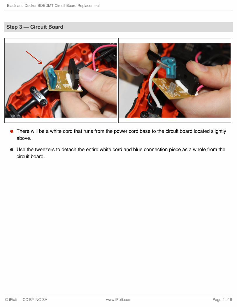
Step 3 — Circuit Board
There will be a white cord that runs from the power cord base to the circuit board located slightlyabove.
Use the tweezers to detach the entire white cord and blue connection piece as a whole from thecircuit board.
Black and Decker BDEDMT Circuit Board Replacement
© iFixit — CC BY-NC-SA www.iFixit.com Page 4 of 5
To reassemble your device, follow these instructions in reverse order.
This document was last generated on 2017-10-14 11:05:04 AM.
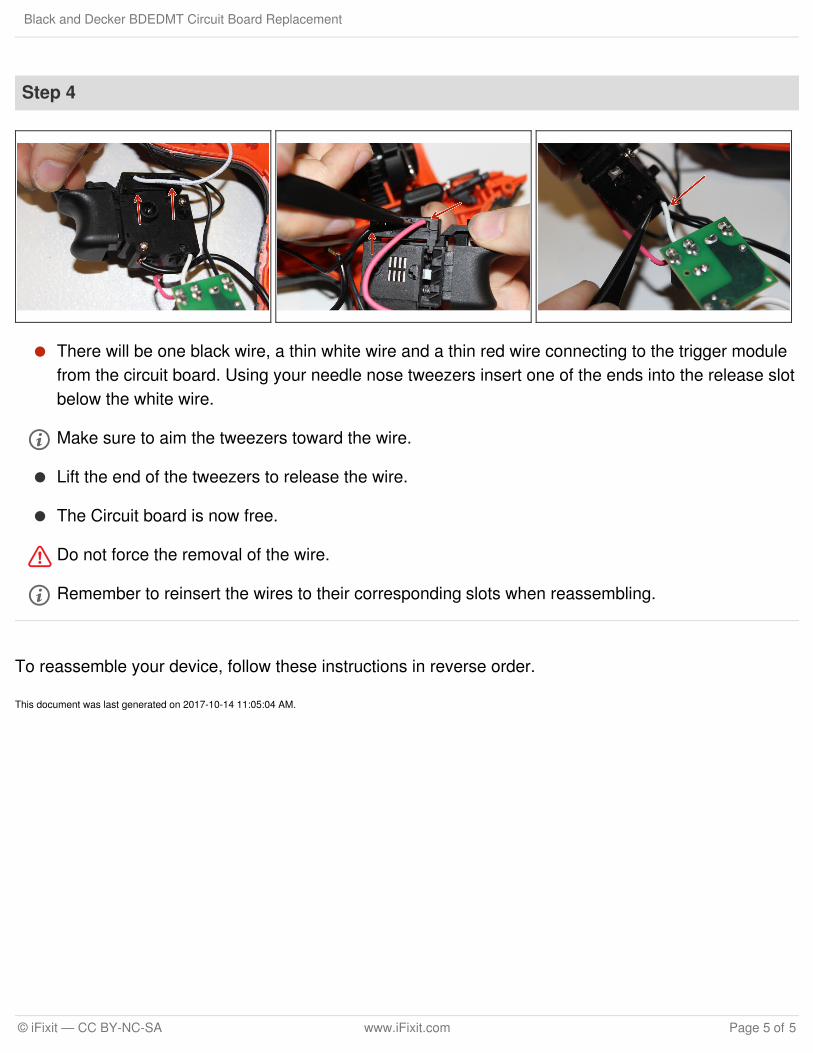
Step 4
There will be one black wire, a thin white wire and a thin red wire connecting to the trigger modulefrom the circuit board. Using your needle nose tweezers insert one of the ends into the release slotbelow the white wire.
Make sure to aim the tweezers toward the wire.
Lift the end of the tweezers to release the wire.
The Circuit board is now free.
Do not force the removal of the wire.
Remember to reinsert the wires to their corresponding slots when reassembling.
Black and Decker BDEDMT Circuit Board Replacement
© iFixit — CC BY-NC-SA www.iFixit.com Page 5 of 5