Embed Size (px)
Citation preview

FM 5-102 COUNTERMOBILITY DISTRIBUTION RESTRICTION. This publication contains technical or operational information that is for official Government use only. Distribution is limited to US Government agencies. Requests from outside the US Government for release of this publication under the Freedom of Information Act or the Foreign Military Sales Program must be made to HQ, TRADOC, Fort Monroe, VA 23651-5000.
MARCH 1985 HEADQUARTERS DEPARTMENT OF THE ARMY

Field ManualNo. 5-102
FM 5-102Headquarters
Department of the ArmyWashington, DC, 14 March 1985
C O U N T E R M O B I L I T Y
T he foundation for engineer doctrine in the AirLandBattle is built with combined mobility, countermobility,and survivability efforts. This manual provides the basic
framework of fielded and developmental countermobilitymethods, planning, and execution. Its purpose is to integratecountermobility into the overall AirLand Battle structure.
Countermobility support is divided into mine warfare andobstacle development, each with an ultimate goal of delaying,stopping, or channelizing the enemy. Mine warfare expands toinclude mine categories, methods and systems of delivery,employment, reporting, recording, and marking. Obstacledevelopment demonstrates innovative techniques and con-ventional improvements in planning and emplacing obstaclesother than minefield.
Countermobility effort is not secluded; rather, it balances withthe other major battlefield missions of mobility and survivability,as well as general engineering and topography. The overallteamwork and planning process are both evident and essentialwith each facet of countermobility.
STANAG IMPLEMENTATIONThe provisions of this publication are the subject of the followinginternational Standardization Agreements: STANAG 2017,Orders to the Demolition Guard Commanders and DemolitionFiring Party Commander (Non-Nuclear); STANAG 2036, LandMinefield Laying, Recording, Reporting and Marking Procedures;STANAG 2096, Reporting Engineer Information in the Field;STANAG 2123, Non-Nuclear Demolition Target Folder; andSTANAG 2889, Marking of Hazardous Areas and Routes ThroughThem.
i
FM 5-102
USER INFORMATIONUsers of this manual are encouraged to submit recommendedchanges to improve the manual. Comments should identify thearea in which the change is recommended. Reasons should beprovided for each comment to allow complete evaluation.Comments should be prepared using DA Form 2028 (Recom-mended Changes to Publications and Blank Forms) and for-warded directly to the Commandant, US Army Engineer School,Fort Belvoir, VA 22060-5291.
When used in this publication, “he,” “him,” and “his”are used to represent the enemy.
ii
FM 5-102
TABLE OF CONTENTS
iii
14 March 1985
FM 5-102
iv

Chapter 1COUNTERMOBILITYON THE BATTLEFIELD
This chapter focuses upon a modern battlefield against anenemy using Soviet style tactics and organizations. Itdiscusses the modern battlefield, emphasizes threat
operational concepts, particularly threat engineers and theircapability to provide countermine and counterobstacle support tothe offense, and covers the importance of friendly countermobilityactivities to deny the threat freedom of movement.
THE BATTLEFIELD
THREAT ENGINEERS
COUNTERMOBILITY REQUIREMENTS
SUMMARY
2
2
14
15
COUNTERMOBILITY ON THE BATTLEFIELD 1
FM 5-102
THE BATTLEFIELD
The most dangerous threat to United States’(US) national interests will most likely in-volve highly trained enemy forces usingSoviet style tactics, organizations, andequipment. The actual battle will be intense,fast, and deadly. United States forces musttherefore be prepared and trained to fight ona future battlefield where—
Highly mobile forces will use combatsystems delivering firepower of unprec-edented volume, speed, accuracy, range,and lethality.
Airspace will be crowded with aerialcombat, surveillance, transport, recon-naissance, and target acquisition systems.
Communications systems will be the targetof indirect fire and sophisticated electronicwarfare operations, making command andcontrol difficult to achieve and maintain.
Scatterable mine systems will severelyaffect ground mobility due to rapid andremote delivery means.
Employment of nuclear, biological, andchemical (NBC) weapons will create anewexperience and add new dimensions to theenvironmental conditions.
Ultimate success on the battlefield willdepend on mobility and countermobilityefforts, not only near the forward line of owntroops (FLOT), but also in rear areas.Successful commanders will need to con-centrate forces at the decisive time and place,make maximum use of unit versatility,exercise movement and maneuver, impedethe opposing force’s movement andmaneuver, and preclude enemy reinforcementof committed units and their resupply.
THREAT ENGINEERS
Engineers play a vital role in the success ofthreat army combined arms operations. Inthe threat view, the greater the increase inmobile warfare, the greater the need forpassable terrain. Therefore, stated in simpleterms, the mission of the threat combatengineers is to keep the offense moving.Threat engineers are organized, equipped,and trained to accomplish this mission underfire and in all environments including NBC.
ORGANIZATIONAll tank and motorized rifle units downthrough the regimental level have organicengineer elements. In combat, these elementsform special engineer combat groups-eitherunder control of parent command or attachedto subordinate commands—to perform directsupport missions. Engineer elements are alsocombined with other branch elements inoperational groupings to perform specific
tasks. At higher echelons (Front or Com-bined Arms Army), considerable engineerreserves are maintained either for con-centrated use as needed, or for attachment tosubordinate formations. This reserve allowsrapid switching of engineer effort from onearea to another, affording maximum tacticaland operational flexibility. Furthermore, it isnot unusual for the senior formationcommander to strip a unit of its engineerelement when that element is required for aconcentrated effort elsewhere on the bat-tlefield.
Doctrine emphasizes that commanders at alllevels must strive for maximum flexibility inusing engineer assets, inasmuch as engineertasks are not isolated but are part of theoverall tactical plan.
Combat engineer units at any level are of two
2 COUNTERMOBILITY ON THE BATTLEFIELD

FM 5-102
general types: engineer special/technicalunits or general purpose engineer units.
Special/technical units perform the followingtasks:
Engineer reconnaissance.
Road and route preparation.
Field fortification construction.
Bridge construction.
Camouflage.
Assault river crossing.
Obstacle construction and/or removal.
Minefield breaching and clearing.
Water supply.
General purpose engineers may perform anyor several of the above tasks, but usually to alesser degree than their special/technicalcounterparts. In either case, the threatenvisions that most if not all of these tasksare conducted under fire or well in advance ofmain assault elements.
Technical repair of pipelines and topographicsurveying are not the responsibility of threatengineer units. In addition, many simple andgeneral engineer tasks are not carried out byengineer soldiers, but by soldiers of othercombat arms. For example, all threat combatsoldiers are expected to be proficient at mineclearance. The operation of tank-mountedmine plows and rollers is a responsibility ofarmored forces, although engineer advice isavailable in deciding whether to employ suchdevices.
The organization of threat engineer units isthe result of careful study and is designed to
accomplish specific objectives. These ob-jectives are:
Conducting engineer tasks necessary tosupport the tactical employment of othercombat arms, especially the movement oftank and motorized rifle elements.
Attaching additional engineer assets tosubordinate elements and maintaining asignificant engineer reserve.
Dovetailing and expanding engineer tasksin the offense by follow-on engineerelements of increased capabilities.
Providing cohesion to the defense andsecurity in the offense by employing mines,obstacles, field fortifications, and antitankdefenses.
The structure of engineer units is constant atthe regimental and divisional levels, but notat higher levels of command. The engineerunits assigned to a Front or Combined ArmsArmy will vary with the level of importanceof the major command in the overalloperational or strategic plan. Generally, aFront engineer reserve is likely to be twice aslarge as that of a Combined Arms Army.
PRINCIPLES OFTHREAT ENGINEER EMPLOYMENTThreat military principles are observed inorder of precedence. To a certain extent,threat military principles appear as re-phrasing of Western principles of war.However, applying these principles is peculiarto threat military theory, and threat units areconfigured and equipped to attain them. Theseeight military principles, in order of priority,are:
1 Mobility and high rates of combatoperations.
2 Concentration of main efforts and creation
COUNTERMOBILITY ON THE BATTLEFIELD 3

FM 5-102
of superiority in forces and means over theenemy at the decisive time and place.
3 Surprise and security.
4 Combat activeness (constant combat andpressure).
5 Preservation of the combat effectivenessof friendly forces.
6 Conformity to the goal.
7 Coordination.
8 Action upon the enemy to the entire depthsof his employment and deep into his reararea.
These principles are basic to a threat officer’sapproach to any combat problem, and willhave a profound effect on any decision made.For example, achievement of high speed inthe execution of combat missions is the firstprinciple, and will therefore take precedenceover the need to avoid casualties and preservethe combat effectiveness of friendly troops.In other words, saving time is more impor-tant than saving lives, since fewer liveswould be lost if the threat commander isallowed to exercise battlefield initiative anddictate the terms of combat. While adheringto these principles, the role of combatengineers is to assist other elements of combatarms to follow them more closely, therebyattaining greater combat effectiveness.
The threat has certain principles peculiar tocombat engineers. These principles arebinding upon the engineer commander andstate that combat engineer operations must—
Correspond to the impending battle con-cept and support the commander’s plan.
Be completed in time to allow thecompletion of tactical activities necessaryin implementing the plan.
Be concealed to deprive the enemy ofintelligence indicators.
Contribute directly to the effect of the mainattack in the offense or the main sector inthe defense.
Be capable of rapid maneuver to adapt tochanging battlefield situations.
Deceive the enemy regarding the directionor location of the main effort.
THREAT ENGINEERSUPPORT OF THE OFFENSE
In the offense, the chief function of engineersis to assist in maintaining high rates ofmovement, which is the premier tacticalprinciple of threat military doctrine. Em-phasis is placed on clearing and maintainingroutes for the advance of combined armsunits, to include breaching or removing minesand obstacles, crossing water obstacles, andassisting in flank protection or protectionagainst counterattack. Engineer recon-naissance, independently or in collaborationwith other reconnaissance means, plays asignificant role in facilitating movement.Camouflage and protection during halts ortemporary assumption of the defense are alsobasic engineer functions.
Secondary attention is given to supportinglogistic operations in rear areas. The practicaleffect of these engineer requirements is tocreate certain key functions which must besatisfied by engineer troops. These functionsinclude:
Engineer reconnaissance.
Movement support.
Mine and countermine warfare.
Wet and dry gap crossings.
4 COUNTERMOBILITY ON THE BATTLEFIELD

FM 5-102
Engineer reconnaissanceThe goal of engineer reconnaissance is toprovide a comprehensive report on thepassability of march routes. Engineer re-connaissance is conducted by engineerelements attached to combined arms orreconnaissance units, or by engineer officersacting as part of the commander’s re-connaissance party which checks the validityof plans made from intelligence withoutactual prior inspection of the terrain.Engineer elements performing this recon-naissance must determine—
The degree of passability of the entireroute.
The location and nature of obstacles to beovercome and the engineer assets requiredto overcome them.
The condition of all crossing sites, wet ordry.
The location and quantity of materialwhich can be used to improve the marchroute.
The nature of the terrain and location ofareas with natural concealment.
In the conduct of engineer reconnaissance,the most commonly employed formation isthe Soviet engineer reconnaissance patrol,Inzhenerny Razvedyvatel’ny Dozer (IRD).The IRD may vary in strength from a squadto a platoon. Commanded by an officer orsenior noncommissioned officer (NCO), it isequipped with the necessary equipment foraccomplishing its task. The IRD will almostalways be vehicle-mounted, utilizing thereconnaissance version of the BRDM or BTR-60. The commander is issued maps and aerialphotographs of the march route and providedwith the column composition indicating thenumber and types of vehicles the route mustaccommodate.
Significance to Friendly ForcesThe appearance of engineer reconnaissanceelements serves as an important intelligenceindicator of impending offensive action. Inaddition, since engineer reconnaissance isnormally conducted one to one-and-a-halfdays in advance of the main force’smovement, it provides highly valuableinformation regarding the timing of threatactivity. Since threat offensive tactics arepredicated upon high rates of movement andengineers are paramount in implementingthis movement, friendly counterreconnais-sance action directed against IRDs willdeprive the threat commander of engineerintelligence vital to executing the tacticalplan. Finally, the documents carried by theIRD commander provide portions of thethreat commander’s actual tactical plan.
When in close proximity to enemy forcesoccupying prepared defensive positions,threat engineer reconnaissance will beconducted in a different manner than when itsupports an approach march. In such aninstance, existing intelligence concerningroads, topography, defenses, and the like,will be initially supplemented by aerialphotography and aerial visual reconnais-sance. Engineers will be attached to manycombined arms reconnaissance elements. TheIRDs will be employed to penetrate defensesto reconnoiter either a specific avenue ofapproach or particular defensive fortifi-cations and obstacles. Additionally, re-connaissance may be conducted by estab-lishing covert engineer observation postsclose to, or actually within, the defensivesector.
One engineer observation post (OP) isnormally established per 2 kilometers of frontin order to observe the entire enemy FLOTand ascertain the engineer action andequipment necessary to properly support theattack. As the attack progresses, these OPscontinue to observe the effectiveness of the
COUNTERMOBILITY ON THE BATTLEFIELD 5

FM 5-102
engineer assault and make recommendationsconcerning alteration of the operation planor commitment of the engineer reserve. Thepurpose of engineer reconnaissance is todevelop intelligence supporting the em-ployment of first echelon assault elements.The value of denying engineer informationthrough aggressive counterreconnaissancecannot be overemphasized. Since assaultengineer tasks are a prerequisite to theexecution of the threat commander’s tacticalplan, any friendly action which interfereswith these tasks will concurrently degradethe execution of the plan.
Movement supportThe threat army believes that, withoutadequate engineer preparation, the approachmarch is sometimes not possible at all.Therefore, the results of engineer recon-naissance serve two purposes:
1 Selecting column routes which require theleast engineer preparation.
2 Planning the employment of engineerassets for any route clearing needed.
Principles of movementConsidering the results of engineer re-connaissance and the tactical requirementsof the operation plan, the commander selectsthe unit’s approach route. The Chief ofEngineer Services then drafts the engineerplan for movement support. This plan isbased upon two principles:
1 Engineer soldiers must be equitablydispersed throughout the march column toinsure proper engineer support to the entireformation.
2 Engineer soldiers must work as far inadvance as possible.
Threat doctrinal texts state that movementsupport elements should ideally operate one-half day in advance of the main force. Themanual task of route preparation usuallyfalls to a temporary organization called amovement support detachment, OtriadObespecheniya Dvizheniya (OOD). SeveralOODs can be formed from the engineerbattalion of the tank and motorized rifledivision, while additional OOD assets existin the engineer companies of the tank andmotorized rifle regiments.
Responsibilities of the OODsSpecific responsibilities include the following:
Clearing and leveling areas of movement.
Building approaches and exits at streams,ravines, or other obstacles.
Constructing bypasses.
Breaching and clearing mines.
Marking routes.
The organization of the OOD may varydepending on the scale of work undertakenand the assets available. In general, thefaster the desired rate of advance, the strongerthe OOD. In most if not all cases, the OODwill be reinforced with tank and motorizedrifle elements to assist engineers in thosetasks conducted under fire. Typical variationsin the structure of OODs are shown in thefollowing illustration. The groups are or-ganized having the following missions:
Reconnaissance and Barricade Destruc-tion Group: Reconnoiters march route,clears obstructions, and selects columnroute.
Road and Bridge Group: Prepares routeand provides crossings.
6 COUNTERMOBILITY ON THE BATTLEFIELD

FM 5-102
Route Marking Group: Marks route and and roller-equipped tanks clear lanesprovides security and traffic control. through the minefield. Using information
previously obtained by an IRD, additionalMoving into position directly behind thedivision’s advanced guard, or sometimesbehind the advanced guard’s point securitypatrol, the OOD normally moves about 1 to 2hours in advance of the head of the marchformation. A typical sequence of activities foran OOD would consist of:
The reconnaissance and barricade de-struction group reconnoiters enemyminefield and obstacles protecting a rivercrossing. Obstacles are cleared byengineers using explosives, while plow-
reconnaissance of the river banks isconducted to determine the exact extent ofpreparation necessary for bridging. Enemytroops in the area are engaged by tank andmotorized rifle elements.
Road and bridge groups improve initiallanes through minefield, prepare banksfor bridging equipment, and emplacebridges.
As preceding groups continue movement,the route marking group emplaces required
COUNTERMOBILITY ON THE BATTLEFIELD 7

FM 5-102
route and bridge markers, establishes mine belt is considered much more effectivetraffic control points, and regulates traffic and efficient against infantry and tanksflow until relieved by military police traffic than trenches, wire, or other fortifications.units. Mines are a much quicker means of erecting a
defense. Consequently, they are widely usedThe threat uses smoke and supporting in- even in offensive operations. In supportingdirect fire as necessary to assist the OOD the offense, engineers employ extensivein accomplishing required tasks. minefield in several situations such as—
Threat doctrine for route preparation stip-ulates that, as an average, a divisionalengineer battalion should be able to prepareup to 100 kilometers of route per day in opencountry where roads or tracks have not beensubjected to specific enemy action to block ordestroy them. If the route has been specificallyinterdicted by the enemy, then only 20 to 40kilometers per day can be achieved, less if theengineer tasks must be conducted under fire,In such cases, it is common for threatengineers to construct a rough track parallelto the planned route, if possible, in order tomaintain the tempo of the advance.
Significance to Friendly ForcesThreat offensive operations are predicatedupon high speed execution and the sequencedarrival and departure of combined armsteams at specific locations at designatedtimes. Thus, dependent upon an exceptionallyhigh degree of coordination, the threatcommander relies to a critical extent upon themovement support activities of hisengineer troops. Action which denies theaccomplishment of engineer route prepa-ration activities may create a potentiallydisastrous situation for the threat com-mander. The delay of an advancing columnby an unexpected obstacle not only disruptscoordination and slows the tempo of battle,but also causes succeeding units to combinewith those in front, creating a highlyrewarding target for friendly fires.
Mine and countermine warfareIn the threat view, the most importantfeatures of mines are speed and ease ofemplacement on the battlefield. Emplacing a
When temporarily assuming the defense.
When protecting against counterattack.
When providing flank protection.
In any future war, the threat believes therewill be no distinct front line nor a clearlydefined forward edge of the battle area(FEBA) or FLOT. Rather, there will be aseries of offensive and counteroffensive axesin the form of spurs and salients. Given thefluidity of combat under such conditions, amine obstacle offers far greater flexibility inemployment than antitank ditches, tetra-hedrons, and other such relatively staticobstacles. Minefield will be the most commonmeans of protecting vulnerable aspects ofoffensive deployment, and mined areas maybe expected to be far greater than thoseencountered in World War II. Although allthreat troops are trained in the fundamentalsof mine warfare, combat engineers arespecially trained to perform this function.The primary combat engineer elementperforming mine warfare support for theoffense is a temporary organization called amobile obstacle detachment, PodvizhnoyOtriad Zagrazhdeniya (POZ), which is formedfrom elements of regimental and divisionalcombat engineers.
In the offense, POZs are positioned on theflanks of the march column, and usually areclosely associated with the antitank reserve.Each POZ will be equipped with up to threePMR-3/60 minelaying trailers with towedmine-carrying vehicles, or the newer GMZtracked armored mine-laying vehicle which
8 COUNTERMOBILITY ON THE BATTLEFIELD

FM 5-102
is rapidly replacing the older PMR-3/60. Incertain instances, the Mi-8/HIP helicopterwith removable mine racks and chutedispensers may be used to emplace minesfrom an altitude of about 5 meters. Adivisional POZ equipped with the GMZtractor is capable of emplacing a 1,000-meterminefield containing 750 to 1,000 mines at 4-or 5.5-meter intervals within 30 minutes onsuitable ground.
Temporary assumptionof the defensiveIf the attack fails, engineers must be preparedto conduct rapid fortification and obstacleactivity in support of the hasty defense. Inthis role, POZs will perform as they do inoffensive combat and emplace mines inaccordance with the overall defensive plan.
Protection against counterattackIn planning the offensive employment of thecommand, the threat commander constantlyevaluates the battlefield for suitable enemycounterattack areas. Areas identified asfavorable are usually those which woulddetract from the maneuver of the combinedarms teams, and be considered vital for mineemployment in order to deny the enemycommander tactical initiative.
Flank protectionEngaging in a battle of dispersion andmaneuver necessarily creates extensiveexposed flanks. In threat theory, preventingenemy exploitation of such a condition relies,on two actions: rapid execution of combattasks before the enemy can react, andprotection of flanks by extensive minefield.During the march to contact and during theengagement itself, POZs actively emplacemines on the flanks of maneuvering units topreclude being attacked by mobile forces ofthe enemy.
In the late 1960s and early 1970s, the tendencyfor a POZ to create an obstacle by alternatingminefield with other antitank obstacles
along a 6- to 7-kilometer front is nowconsidered ineffective, as is the practice oflaying long strip minefield without coveringthem by antitank fire. Current threatteaching stresses the need for anititank gunsto engage tanks as soon as they encounter theminefield. Thus, a short, deep mine and gunobstacle belt is preferred to a long, thin one,making choice of position critical.
Because of the possible need to recoverminefield as the advance progresses,antipersonnel mines are rarely included inan antitank minefield laid in support ofoffensive operations. Minefields left behindare clearly marked and recorded, and theirlocations are reported to the Chief of EngineerServices.
Significance to Friendly ForcesIn the offense, the commander employs minesin areas evaluated as offering the enemy asignificant advantage to interfere with thetactical plan. Thus, the detection of mine-laying activity offers the friendly force anindication of the manner in which the threatcommand will be employed, and highlightsthose areas deemed critical to success.
The threat, in planning for the widespreademployment of mines, fully expects anyenemy to engage in extensive mine warfare.Consequently, countermine warfare is anextremely important task entrusted to combatengineers. Breaching lanes through enemyminefield is critical to the goal of keepingthe attack moving. Equally important is thedesirability of conducting mine breachingoperations covertly, whenever possible, topreserve surprise. When attacking from themarch, the location of enemy minefield isthe responsibility of engineer reconnaissancepatrols (IRDs). The IRD is equipped withseveral types of mine detectors, the mostcommon being the DIM metallic mine detectormounted on the UAZ 69, ¼-ton, 4 x 4 LightUtility Vehicle. The DIM is synchronizedwith the vehicle’s ignition system and, upon
COUNTERMOBILITY ON THE BATTLEFIELD 9

FM 6-102
detecting a metallic mine, cuts out theelectrical system and kills the engine. TheIRD reconnoiters the limits of the minefieldand marks it for the following movementsupport detachment (OOD).
In breaching the required number of lanesthrough the minefield, the OOD will employseveral types of mine breaching equipment.The normal threat method of breachingminefield during an assault or rapid advanceis to employ mine plows fitted to the leadtanks. Although engineers will reconnoiterthe minefield, the initial breaching is notprimarily an engineer task. The KMT-4 andKMT-6 plows are normally employed on thescale of one per platoon of three to four tanks.Engineers assist in fitting these and plow-roller combinations (KMT-5s) commonly usedfor minefield reconnaissance. The threatestimates clearing speeds of about 6 kilo-meters per hour (kph) for plow-fitted tanks,and about 10 kph for roller-fitted tanks.Combat vehicles follow these plow-equippedtanks in the breaching of a minefield. Thethreat employs a mine-clearing devicemounted on the BTR-50 PK Armored Per-sonnel Carrier (APC) (two to each divisionalengineer battalion). This device fires andthen detonates an explosive hose (line charge)across the minefield. It clears a lane about180 meters long by 6 to 8 meters wide. Thisequipment is particularly useful during anassault river crossing when there areminefield on the far bank and amphibiousvehicles may have to initially operate in thebridgehead without tank support.
Another mine-clearing device is the explosiveline charge. It consists of three separatelinear charges, a nose section, and a detonatorbox. Each linear charge may be assembled toany desired length by connecting 2-metersections together with threaded collars. Thelight, sheet metal, 5-centimeter-diameter,tubular sections are filled with cast tri-nitrotoluene (TNT) explosive at 9 kilogramsper linear meter. This device is versatile in
that it may be used as a single, double, ortriple charge. The forward end section isfitted with a roller to facilitate insertion of thecharge into a minefield. The device isassembled in a rear area, towed by tank to theminefield’s edge, pushed into the minefield,and fired. The triple line charge will clear a6-meter-wide path along the entire length ofthe charge. A squad can assemble a 500-meter-long triple charge in 1 to 1.5 hours.
Bangalore torpedoes are also used. Sections,2 meters in length, carrying 6 kilograms ofexplosive, are connected by collars. Theclearance depth of a path 1 to 2 meters wide islimited only by the manageable weight thatcan be manually pushed into the minefield.
The number of lanes to be cleared depends onthe terrain and the number of columns in theassault echelon. For a leading battalion inthe assault on a main axis, six to eight lanesmay be required, one for each assaultingplatoon. In secondary sectors, as few as twolanes may be sufficient. However, an averageof four to six lanes can be expected with atleast two developed into permanent lanes, 6to 8 meters wide, for passage of artillery andlogistic vehicles. Engineers mark minefieldlanes and provide traffic control through theminefield. The routes leading from a startline to each lane are marked with redtriangular metal flags and black-and-whitetapes. Illuminating markers may be used atnight. Routes through friendly minefield aremarked by signs of various shapes placed notless than 20 meters apart on both sides of theroute. If possible, they are positioned so asnot to be visible from enemy positions.
In attacking from line of march, manualmine breaching is carried out only undercertain conditions:
As nuisance minefield along or on routes,especially around craters and demolitions,to allow the route clearing unit to workfreely.
10 COUNTERMOBILITY ON THE BATTLEFIELD

FM 5-102
On approaches to water obstacles andwater mines.
To maintain surprise, especially at nightor when the threat wishes to make a gap intheir own minefield.
When other mine breaching equipment iscommitted.
When conducting assault breaching opera-tions against a defended enemy minefield,the usual practice is to attack with combinedarms teams led by combat engineers andsupported by artillery and tactical aviation.Such a formation is necessary if the combatengineers are not to suffer crippling losses to
defensive fires. Artillery, in particular, playsa major role in suppressing defensive firesand allowing the execution of engineer tasks.If artillery support is not available or is tooshort in duration, the first wave of the attackis led by plow- and roller-equipped tanks,while combat engineers closely follow towiden lanes. Here again, the use of plow- androller-equipped tanks is not an engineerresponsibility, but an engineer functioncarried out by tank soldiers. Another meansof lane improvement entails mine clearingtanks dragging a variable length of explosiveline charge. The charge is detonated to clearmines not uncovered by the plow or roller.Our minefield should be deep enough topreclude the threat from breaching the entiredepth with one line charge. The threatbreaching capability with one line charge iscurently in the 50-meter range. A threatsquad can assemble a 500-meter-long triplecharge in 1 to 1.5 hours by coupling the 50-meter sections together. Planners shouldcheck the current threat capability forbreaching before determining what sizeminefield is most effective.
As with much of threat engineer activity,threat mine and countermine operationsprovide both intelligence and tactical valuesto friendly forces. Minefield breaching
activity is indicative of impending threatoffensive action, and the identification ofsuch activity will greatly assist in deter-mining times and locations of attack.However, it must be kept in mind that threatdoctrine calls for the conduct of bogus mineclearing activity as part of cover anddeception plans. Tactically, the denial ofthreat countermine actions serves to deprivethe threat commander of the tactical initiativewhich his entire operation plan is based.
River crossingsThreat military doctrine dictates that,whenever possible, water obstacles along abroad front are crossed at multiple pointswithout pause in the march or the advance.This tactic is designed to rapidly overwhelmenemy defenses and maintain the tempo ofthe attack. In the threat view, a delay at amajor water obstacle can jeopardize thesuccess of an entire offensive operation inconventional combat, and is certain to destroylarge forces massed for the crossing during anuclear war. Consequently, the threatrecognizes two distinct forms of rivercrossing, hasty and deliberate.
Hasty crossingThe hasty crossing incorporates the featuresof rapid movement previously mentioned.The attacking force crosses the water obstaclein stride, does not stop to consolidatebridgeheads, and continues the advancewithout pausing. This is the preferred form ofriver crossing.
Deliberate crossingThe deliberate crossing is conducted when anattempted hasty crossing has failed, or whenhostilities are being initiated against a well-prepared enemy occupying a river linedefense. It is characterized by more detailedplanning, extensive buildup and preparation,and a greater degree of centralization thanthe hasty crossing.
The role of combat engineers in both types of
COUNTERMOBILITY ON THE BATTLEFIELD 11

FM 6-102
crossing is critical. While all arms are fullytrained in their individual roles in rivercrossing operations, engineer functionsprovide the margin of success. It is not thepurpose of this section to examine rivercrossing operations in their entirety, but todefine the role of engineers within the overalleffort. For a complete account of the conductof river crossing operations by all arms, seeDefense Intelligence Agency (DIA) Publica-tion DDI-1150-13-77.
Engineer support to assault river crossingsby threat forces occurs in the following areas:
Engineer reconnaissance of watercrossings.
Route and site preparation.
Crossing preparation and execution.
Site protection.
Support to units within the bridgehead.
Engineer reconnaissanceof water crossingsIn the threat view, the key to a successfulriver crossing is thorough reconnaissance todetermine both the tactical situation and thetechnical characteristics of the river and itsbanks. As a general principle, reconnaissancewill be carried out across a wide front to avoidfocusing enemy attention on one area.Additionally, this activity identifies thenumerous crossing sites needed to supportthe crossing of widely dispersed units.Engineer reconnaissance personnel willattempt to ascertain the following infor-mation at each site:
River width, depth, and current.
Entry and exit gradients.
River bottom composition.
Bank composition and height.
Approach and exit routes.
Critical terrain features dominating bothbanks.
Possible fording, ferrying, bridging, andsnorkeling sites.
Information on enemy defenses.
In obtaining this information, engineers may,as in other offensive operations, accompanycombined arms reconnaissance teams; or,engineer patrols (IRDs) may operate in-dependently. An IRD will usually operatefrom the BRDM engineer reconnaissancevehicle and will be equipped with a variety ofreconnaissance equipment. In some in-stances, engineers are clandestinely droppedby parachute directly on the water obstacle.
A typical reconnaissance mission for asquad-size IRD might require the recon-naissance of two sites in a 500- to 600-metersector, a task usually accomplished in 4hours. Scuba-equipped engineers check forwater mines and test riverbed conditions.Other members of the IRD select and markconcealed approach routes; obtain hydro-graphic data by using depth finders andwater current meters; determine river bankconditions and the presence of existing ormilitary obstacles; identify enemy defensesand conduct bogus reconnaissance activityin other areas to avoid disclosing the maincrossing sector.
Significance to Friendly ForcesEngineer reconnaissance performed insupport of water crossings has both in-telligence and tactical value to the friendlyforce. Conducting engineer reconnaissancewill assist in identifying planned crossingsites for combined arms teams and the timesof attack. Such information is of extremeimportance in planning the friendly tactical
12 COUNTERMOBILITY ON THE BATTLEFIELD

FM 5-102
Crossing preparation and executionresponse. Counterreconnaissance, whichprevents the accomplishment of engineerreconnaissance missions, deprives the threatcommander of information vital to thesuccessful execution of attack.
Route and site preparationRoute preparation of approaches to crossingpoints will follow the same procedures as inthe approach march. Movement supportdetachments (OODs) will accompany thevanguard elements of advance forces toprovide trafficable conditions for the typesand numbers of vehicles in the column. Adivision will usually cross a river on a widefront at a minimum of four points (sometimesup to eight) simultaneously, seeking to findsuitable areas for each type of crossingmeans. This requires the engineer staff tocarefully plan and allocate engineer assets.
The preparation of proper entry and exitbank gradients is crucial and depends uponthe results of the reconnaissance effort.Earthmoving equipment and explosives areused in preparing bridge approaches andentry and exit points at ford, ferry, and swimsites. Rapid execution of these tasks isessential, since the actual crossing unitsfollow closely behind and depend on suitablyprepared crossing points before commencingoperations.
Significance to Friendly ForcesSite preparation is a critical phase of a threatriver crossing operation. Interference withsite preparation activity translates directlyto interference with the sequence and timingof the engineer effort, which the entirecrossing is dependent upon. If the sitepreparation effort can be denied, the followingcrossing units will either be unable to performtheir function or forced to halt. The tempo ofthe attack will be disrupted, and theconsequent bunching of units will createlucrative targets. For these reasons, sitepreparation represents the most vulnerableaspect of a threat river crossing.
Following the initial site preparation, andimmediately prior to actual crossing, finalpreparatory activities are executed. Pre-viously located water mines are destroyed byscuba-equipped engineers using explosives.Where necessary, metal matting is emplacedat soft bottom fords. Engineers in amphibiousAPCs accompany initial assault waves andassist in reducing defenses on the far bank.
During the actual crossing, the ferry opera-tion and bridge emplacement are solelyengineer functions. Additionally, engineersare responsible for traffic control anddirection at all crossing sites. In the latterrole, engineers insure that the crossing isconducted at a high rate of speed, a re-quirement considered to be extremelyimportant. Threat doctrine establishes thedesired crossing time for the division combatelements as 3 hours during daylight and 6 to8 hours at night.
Significance to Friendly ForcesThe primary role of engineers during thisphase is providing the physical means bywhich the bulk of the division crosses. Thisphase of engineer operations also marks thearrival of major combined arms teams, and isusually supported by artillery fires. In mostcases, it will be conducted under the protectionof the air defense umbrella.
Site protectionCommencing with initial site preparationand continuing through the conduct of thecrossing, engineer elements are responsiblefor protecting the site, equipment, andcombined arms teams from floating minesand enemy raids. Scuba divers and powerboats will constantly patrol both upstreamand downstream approaches to the crossingsite, and outposts will be established alonglikely land approaches.
Significance to Friendly ForcesWhen planning raids against threat gap-crossing sites, the presence and locations of
COUNTERMOBILITY ON THE BATTLEFIELD 13
FM 5-102
these security forces already established byprior reconnaissance should be considered.
Support to units withinthe bridgeheadAs the threat force establishes itself on theopposite bank, elements of the engineerreserve accompany combined arms teams inperforming engineer tasks necessary to keepthe advance moving. In this role, engineersfunction in the same manner as whensupporting the attack from the line of marchor when in contact with the enemy. Thecrossing site will gradually become the
responsibility of lines of communicationtroops, and the combat engineers will rejointhe division and be prepared to support thenext crossing operation.
Significance to Friendly ForcesAs with other threat engineer activity, theshift of engineer emphasis accompanies ashift in tactical emphasis. Friendly actionwhich destroys or damages bridging andferrying equipment during this phase willreduce the threat ability to conduct sub-sequent river crossings until equipment isreplaced.
COUNTERMOBILITY REQUIREMENTS
In order for the threat to attain its primarymilitary principle, Mobility and High Ratesof Combat Operations, it is imperativethat they preserve their ability to move andmaneuver on the battlefield. Threat forcesare designed, organized, trained, andequipped to accomplish this principle aboveall others.
Friendly US countermobility tasks musttherefore be designed and executed to slowthe movement rate specified by the threat.The use of countermobility by friendly forcesmust be integrated into the concept ofoperations not only to impede threat mobility,but to increase the kill probability of friendlyfirepower. Obstacles must be sited to reinforcethe terrain and maximize the effectivefirepower from friendly battle positions.
Countermobility operations will be used alongthe FLOT as well as deep into the threat reararea. The use of scatterable minefield givesfriendly forces a capability to deny threatmobility anywhere on the battlefield. The use
of scatterable minefield should be carefullyplanned and executed so that friendlymobility during future operations is notimpeded.
Countermobility execution is primarily theresponsibility of combat engineers. Theengineer and the tactical commander mustdecide early in the planning process how tobest position obstacles to increase theeffectiveness of friendly fire and maneuver.Tactical commanders must establish counter-mobility priorities early in the planningprocess. Early planning will enable maximumeffort to be devoted to those countermobilitytasks deemed most critical.
Countermobility activities are essential inorder to defeat the first principle of the threatarmy; that is, delay, channel, or stop theoffensive movement. An analysis of recentwars shows that effective and well-plannedintegration of countermobility activities andfirepower can enable an outnumbered forceto win.
14 COUNTERMOBILITY ON THE BATTLEFIELD

FM 5-102
SUMMARYIn supporting offensive operations, the roleof threat combat engineers is to keep theoffense moving. The extreme importance ofthis effort to the overall conduct of the offensecannot be overemphasized. As has been noted,threat offensive combat is predicated uponmobility, high rates of advance, surprise, andsecrecy, and the close coordination of allarms. While first appearing to be highly fluidin nature, close inspection reveals threatstyle offensives to be predicated upon thecarefully synchronized and sequencedinterplay of rapidly moving units.
The mission of engineers is to createconditions of movement which will allow thisnoticeably complicated activity to occurunhindered, and enable the threat com-mander to enjoy total tactical initiative whiledenying it to the enemy.
Combat engineers are thus one of the keyelements of the offense. Any friendly activitywhich prevents combat engineers fromaccomplishing their mission will seriouslyinterfere with the actions of combined armsteams and create exploitable tacticalsituations for the friendly commander.
COUNTERMOBILITY ON THE BATTLEFIELD 15
Chapter 2COUNTERMOBILITY FUNDAMENTALS
T his chapter provides a standard classification and adetailed discussion of existing and reinforcing obstacles.The principles of terrain evaluation and the employment of
all of obstacles to reinforce existing terrain are also presented.
TYPES OF OBSTACLES 17
EXISTING OBSTACLES 18
REINFORCING OBSTACLES 27PRINCIPLES OF OBSTACLE EMPLOYMENT 37
SUMMARY 42
16 COUNTERMOBILITY FUNDAMENTALS

FM 5-102
TYPES OF OBSTACLES
An obstacle is defined as any obstruction can be cultural such as towns or railroadthat stops, delays, or restricts movement or embankments. Reinforcing obstacles aremaneuver. Obstacles can exist naturally suchas a river or a cliff, or can be man-made suchas a minefield or tank ditch.
Obstacles are grouped into two generalcategories, existing and reinforcing, asshown. Existing obstacles are alreadypresent on the battlefield and not placedthere through military effort. They may benatural such as lakes or mountains, or they
placed on the battlefield through militaryeffort and are designed to strengthen theexisting terrain to slow, stop, or canalize theenemy. Reinforcing obstacles are limited onlyby imagination, time, manpower, or logisticconstraints. They include blowing a roadcrater, constructing a log crib, or installing aminefield. Scatterable mines are reinforcingobstacles emplaced by various deliverysystems such as artillery or aircraft.
COUNTERMOBILITY FUNDAMENTALS 17
FM 5-102
EXISTING OBSTACLES
The terrain, as it exists, can be a significantasset to the commander who is best able toanalyze and use it advantageously. Terrainis not just the field where the battle isfought—it is very much a part of the battleitself. The commander at any level who makesthe terrain work in a positive manner againstthe opponent will most likely win.
There are many things a commander needsto know about the terrain on which US andenemy forces must move, maneuver, andfight. Some of the more obvious items are:
Roads and bridges.
Built-up areas.
Soil and trafficability.
Slope.
Rivers and streams.
Visibility, climate, weather, and theireffects.
The commander’s course of action willlargely depend on the characteristics of theterrain and intended use of it. The com-mander’s action includes movement, maneu-ver, and weapons siting to destroy the enemy.All ground movement, friendly or enemy, willbe dictated by existing obstacles.
A good analysis of the terrain in the areas ofinfluence and interest should answer thefollowing questions:
Where are the mobility corridors andavenues of approach? (Where will theenemy come from? Where can I go?)
How large are the mobility corridors andavenues of approach? (What size enemy orfriendly force will they support?)
What is the trafficability of the avenues ofapproach? (How fast can the enemy or Itravel and with what type vehicles?)
Where is the key terrain? (What terrainwill provide a significant advantage to theone who controls it?)
What are the fields of fire? (With whatweapons and at what ranges can I engagethe enemy? Or be engaged?)
Where are the choke points or extensiveobstacle areas? (Where are possiblelocations to place reinforcing obstacles?)
These questions are not inclusive, but ifanswered and analyzed, they will providesignificant information on how to preparethe battlefield and allocate combat power.
Determining existing obstacle locations is akey element in terrain analysis. The mostcritical questions are how and where do weget information concerning terrain andexisting obstacles. The best source is an on-the-ground reconnaissance accomplished bythe units who will fight the battle. However,this is not always possible due to lack ofresources or enemy control of the areas aboutwhich we need information. Corps anddivision terrain teams organic to the TheaterArmy Topographic Battalion collect, analyze,and provide important topographic, hy-drologic, and climatic data. Terrain analystsassess observation and fields of fire, coverand concealment, obstacles to movement,key terrain, and avenues of approach. Inputto the force engineer and G-3 is especiallyimportant for obstacle planning. Engineerterrain analysts work as a team withintelligence analysts to collect raw terraininformation and convert it into processedintelligence. Topographic units provide avariety of products including cross-countrymovement maps, overprinted maps, and
18 COUNTERMOBILITY FUNDAMENTALS

FM 5-102
various scale tactical maps. Topographicsupport is invaluable in making a thoroughterrain analysis.
Analysis of terrain and existing obstaclesshould focus on the mobility of tanks. Tacticsof enemy combined arms forces are designedaround the mobility of tanks. The tank is theprimary vehicle we want to restrict, delay,stop, and kill. This antitank orientation ofterrain analysis and obstacle developmentnarrows our focus and makes the task moresimple. By focusing on the tank, the terrainanalysis team can assist the commander inidentifying those existing obstacles thatrestrict, channelize, delay, or stop the mobilityof tanks.
Systematic terrain analysis using all assetsavailable reveals the existing obstacle valueof the terrain. Conditions which should beconsidered when analyzing terrain includedrainage features, slope and relief, vege-tation, cultural features, and climate. Theobstacle value of each condition is evaluatedindividually in conjunction with traffic-ability. Then, their combined effects becomethe obstacle value of the terrain.
DRAINAGE FEATURESDrainage or surface water features includerivers, streams, canals, lakes, ponds,marshes, swamps, and bogs. Such featuresare obstacles whenever the water becomesdeep or turbulent enough to threaten thesafety of soldiers and the operation ofvehicles. Drainage features are also obstacleswhen swamps, marshes, bogs, and the likemake soil conditions impossible for cross-country movement.
Large riversLarge, unfoldable rivers are formidableobstacles because they must be crossed bytactical bridging, swimming, ferrying, orspecial deep water fording. Ease of crossingthese rivers is determined by the width, depth,velocity, turbulence, bank and bottomconditions, rapid tactical bridging available,and existing bridges.
Small rivers, streams, and canalsMinor fordable rivers, streams, and canalsare much more numerous than major riversand their tactical value as obstacles shouldnot be overlooked. These features are variablein effectiveness as obstacles. Carefulplanning is required to integrate them into
COUNTERMOBILITY FUNDAMENTALS 19

FM 5-102
the obstacle system. Watercourses frequentlyconstitute elongated obstacles in terrainwhich may otherwise be excellent formovement. Drainage also influences theorientation of the road net and direction ofmovement in an area. The destruction of afew selected bridges can force cross-countrymovement or long detours. During floods,minor rivers and streams can become majorobstacles. They can cause conditions whichextend the obstacle effect for a considerableperiod by damaging temporary and expedientbridges, and by deepening the originalchannel of the river or stream, thus makingaccess or egress difficult or impossible.
Weather effectsAlthough streams are normally small andslow during periods of low precipitation, andlarge and rapid during periods of highprecipitation, the relationship is not alwaysthis simple. Melting snow, for example, maycause high water downstream even in regionswhere rainfall is low. Continuous below-freezing weather can reduce stream flow eventhough precipitation may be high.
In winter, ice may be strong enough to supportvehicles; then, instead of being obstacles,water bodies may become the preferredavenues for movement. Lightly loaded 2 ½-ton trucks can move on ice 0.3-meter (10inches) thick. Movement on ice is risky,however, because of weaknesses caused bywater flowing from springs and other areasof swiftly moving water.
In arid regions, dry stream channels maybepreferred avenues for movement duringperiods of little or no flow. However, theremay be quicksand or other soft places wherevehicles bog down. Also, there is the dangerof flash floods.
FordingFordability of a stream expresses how easilyit may be crossed without the means of
bridging or ferrying. Fordability depends oncharacteristics of both the vehicle and thestream. The significant characteristics ofstreams are:
Width of channel.
Depth and velocity of water.
Nature of bottom.
Height, slope, and strength of banks.
FORDING IS POSSIBLEIF DEPTH AND BOTTOM
PERMIT ACCESSAND EGRESS.
These characteristics may vary inde-pendently so that fording of even the smalleststream requires selecting a site wherefavorable conditions coincide. A stream is aminor hindrance when a ford is availableand usable with little or no improvement. Astream is a major hindrance if a suitable fordis lacking, or if fording requires considerablepreparation of approaches, reinforcement ofbottoms, or the use of special equipment onvehicles.
TANKS CAN“SELF-BRIDGE”
UP TO 3M.
A tank can bridge stream channels less than3 meters wide; however, wheeled vehicles donot have this capability. Once the self-bridging capability of tracked vehicles isexceeded, streams can be crossed only bybridging, ferrying, or fording. Although thewidth of a stream is significant to bridging, itis relatively insignificant to ferrying(provided it is wide enough) and fording.However, the wider the stream, the greaterthe hazard involved. For fording, thepermissible maximum depth of water formost tanks is between 0.9 to 1.5 meters (3 to 5
20 COUNTERMOBILITY FUNDAMENTALS

FM 5-102
feet); and for trucks, about 0.9 meter (3 feet).Vehicles can be equipped with deep waterfording devices that will enable them to crosswater bodies as deep as 5 to 6 meters (17 to 20feet). Often, a ford may be negotiated withminor difficulty by the first few vehicles, butthe ones remaining will be unable to crossbecause bottom conditions or approacheshave deteriorated with use.
TANKS CAN FORDWATER UP TO
1.5M DEEPAND
1.5M/SECOND VELOCITY.
Stream velocities should be less than 1.5meters (5 feet) per second for reasonably safefording. The bottom of stream channels mustbe firm enough to support vehicles. Bottomsmade up of fine-grained material can preventfording even though the water may be only afew inches deep. Suitable bottoms arerestricted to those that are sandy, gravelly, orrocky; but even sandy bottoms may give wayunder the weight of vehicles, or boulders mayprevent vehicular movement. The banks alsoare important. Hard, vertical banks will beobstacles to tanks, if bank height exceeds 1.5meters (4 feet), and to trucks, if bank heightexceeds 0.3 meter (1 foot). Greater heights canbe tolerated if the vehicles can get adequatetraction or if assistance such as winching isused. The type of the material composing thebanks may be significant. Banks made up offine-grained soils may fail under repeatedtraffic. Sandy and gravelly materials usuallyprovide adequate strength and durability.
GROUND RECONIS ALWAYS
BEST.
Adequate information (river studies, specialmaps) is commonly available on largestreams, but generally not for the smallstreams. Ground reconnaissance is always
the best source of information; for manyareas, it is the only reliable source. If on-siterecon is not possible, then topographic andgeographic maps, reports, and aerial photo-graphs are often the only sources of in-formation available. Occasionally, usefuldata can be found in publications on geology,agriculture, soils, and forestry.
Lakes, ponds, swamps,marshes, and bogs
Large lakes make excellent obstacles. Theyare usually unfoldable, unable to be bridged,and must be bypassed. Smaller lakes andponds in themselves are not difficult tobypass; however, when connected by streams,they are easily integrated as part of anobstacle system. Because lakes can be crossedby amphibious vehicles or boats, beach andunderwater obstacles should be used todiscourage enemy ferrying efforts. Whenlakes are frozen, they may lose their value asobstacles. Swamps, marshes, and bogsseverely restrict mobility and force thecanalization of vehicular movement ontocauseways, greatly increasing vulnerabilityto air attack, artillery, or direct fire weapons.Historically, swamps have been avoided byattacking armies. Swamps and marshes over1 meter deep maybe more effective obstaclesthan rivers, since causeways are usuallymore difficult to construct than bridges.
SoilsSoil trafficability, especially when consideredin conjunction with climatic conditions, is avery important factor in evaluating cross-country movement. Obtaining the necessaryinformation, however, is difficult and time-consuming; and, properly evaluating traf-ficability strength of soils is a complicatedprocess.
SOIL TRAFFICABILITY ISDIFFICULT TO EVALUATE,
DETERIORATES WITH USE, ANDVARIES WITH MOISTURE.
COUNTERMOBILITY FUNDAMENTALS 21

FM 5-102
Engineer soils analysis personnel andqualified photo-interpreters are capable ofestimating soil.strengths usually required byhigher headquarters for planning purposes.The load-bearing capacity of fine-grainedsoils such as clay, loam, and silt is sig-nificantly affected by soil moisture due to theeffects of drainage on the water table orweather. Artificially produced high-watertables have made obstacles of meadows orpaddy fields which covered large areas.Further, the long-term use of manure forfertilizer adds organic material that reducessoil’s trafficability when wet. The combi-nation of soft or slippery soils, and evenslight slopes, will stop many vehicles. Tanks haveextremely low ground pressures (8 to 12pounds per square inch (psi); 0.56 to 0.85kilograms per square centimeter (kg/cm2)).They have less difficulty with most soils thanother vehicles unless unusual wetness orrepeated traffic have reduced normaltrafficability.
BEARING STRENGTHLESS THAN
8 PSI STOPS TANKS.
SnowSnow creates a special cross-countrymovement problem related to soils. Though itis seldom deep enough to be a serious obstacleto tracked vehicles, snow in the spring or fallmay occur over saturated, untrafficableground. It is considerably more of a hindranceand hazard to wheeled vehicles, as most willbecome immobilized when the depth of thesnow reaches one third of the tire’s diameter.Snow reduces slope climbing ability, max-imum payload capacity, and maneuverabilityand speed of all vehicle operations.
SLOPE AND RELIEFSlope is the inclined surface of a hill,mountain, ridge, or any other part of theearth’s land surface. It is the inclination notonly of major surface relief features (hills and
mountains), but also of minor relief featuressuch as ditches, small gullies, mounds, lowescarpments, small pinnacles, and sinkholeswhich generally do not appear on topographicmaps. Although some of the minor relieffeatures might be considered a roughnessfactor rather than slope, they are included inthe general slope factor because their obstaclevalue is due to the steepness of their slopes,banks, or faces. Short, vertical slopes or“steps” higher than 0.3 meter (1 foot), willslow wheeled vehicles, and 1.5 meters (4 feet)will stop tanks.
STEPS OF1.5M HIGH
WILL STOP TANKS.
In mountainous areas, the steep slopescommonly make cross-country vehicularmovement either difficult or impossible.Movement will be channelized by existingterrain. The amount of slope is usuallyexpressed as a percentage, which is thenumber of meters of elevation difference per100 meters of horizontal distance. Mostmilitary vehicles are able to climb slopes of 60percent (about 30/35 degrees) under optimumconditions. This limit, however, is too great tonegotiate in military operations. Inevaluating terrain for cross-countrymovement, 45 percent (about 27 degrees) iscommonly used as the reasonable upper limitfor tanks, and 30 percent (about 17 degrees)for trucks. Wet weather, trees, unfavorablesoil conditions, snow, boulders, and theemployment of reinforcing obstacles maymake gentle slopes impassable.
SLOPE OF45% (27°)
IS PRACTICAL UPPERLIMIT FOR TANKS.
The most reliable information on slopes,particularly short, steep ones, is obtained byon-site reconnaissance. At best, however,
22 COUNTERMOBILITY FUNDAMENTALS
FM 5-102
slope can be determined on only a smallportion of the area by this procedure.Topographic maps are useful but somefeatures may not be shown; for example,small gullies. Terrain teams are the bestoverall source of up-to-date information todetetmine slope and other terrain informationif an on-site reconnaissance is not possible.
VEGETATIONVegetation includes not only natural, “wild”vegetation, but also cultivated forests andcrops. Forest vegetation is the primaryconcern in cross-country movement. Treesare the principal obstacles to movement.Although high grass and brush can obstructvision, they are of relatively little significancein most cases. Nearly all forests, however,have a slowing effect on movement.
The problem is to determine whether aparticular forest will slow movement slightly,drastically, or stop it altogether. Temperatezone forests tend to canalize movement sincethe roads, trails, and firebreaks through themprovide the only means for rapid movement.Reinforcing obstacles readily strengthen thedefensive value of woods, and are placed bothoutside and inside the wooded area to delaythe advance of the enemy and better utilizesupporting fires.
TREES 20 TO 25CMIN DIAMETER,
SPACED NOT MORE THAN5M APART,
ARE OBSTACLESTO TANKS.
Tree size and density, soil condition, slope,and depth of forests contribute to theirobstacle value. Forests with trees 20 to 25centimeters (8 to 10 inches) in diameter aretank obstacles, and 5-centimeter (2-inch)stands will stop most wheeled vehicles. Fullydependable criteria pertaining to the size oftrees, and the significance of species and root
systems, have not been determined. Mediumtanks, for example, have pushed over singletrees as much as 30 centimeters (12 inches) indiameter. Overturning trees within standscan also create complications; for example, ifseveral trees are pushed over, some willinterlock with other trees to form a betterobstacle to movement. The protruding rootsystem and trunks of overturned trees areobstacles to vehicles. The critical averagedistance between trees in forests where thetrees are too big to be pushed over is about 3 to5 meters (10 to 16.5 feet), depending uponwhether the trees are regularly or irregularlyplanted. Although this distance may be wideenough for the vehicle to pass through, inmost cases there is no room for turning.Reconnaissance is especially important as asource of vegetation information for tworeasons. First, two of the characteristics-thesize of trees and the distances betweenthem—are seldom recorded. Second, the sizeand distances frequently are difficult todetermine from aerial photography. Treeblowdown during nuclear attack will presentsignificant mobility problems. Forested areaswhich have been affected by blast will beimpassable to tracked and wheeled vehicles.
CULTURAL FEATURESCultural features are constructed works suchas stone walls, hedgerows, dikes, canals,drainage ditches, embankments, cuts, fills,and built-up areas, as well as damaged orabandoned vehicles and mobile equipment.Some of these features are considered underthe slope factor, some under streams, andsome—such as built-up areas—are frequentlynot evaluated in cross-country movementstudies. Cultural features are treated asa separate factor here to insure that theyare not overlooked in evaluating terrain forcross-country movement. The obstacle valueof a cultural feature depends on its sizeor extent, location, and construction. Largecities and towns that have many masonrybuildings located astride principal
COUNTERMOBILITY FUNDAMENTALS 23

FM 5-102
communication routes can become obstaclesof considerable importance because they canbe reduced to rubble and restrict enemymovement. Even if gaps are cleared throughthe rubble and debris, movement is stillcanalized. The natural obstacle value ofbuilt-up areas can be readily reinforced, andthose properly located to control approachesor key terrain can be developed into for-midable strongpoints.
CRITICAL FACTORS OFCULTURAL FEATURES ARE
SIZE, LOCATION, ANDCONSTRUCTION.
Roads and railroadsAnother extremely important cultural featureis the road and railroad net. It will have afundamental influence on an attacker’s choiceof approaches, because—
The anticipated rates of advance will forcethe attacker (except the lead elements ofhis main body) to move on roads, unlesscombat or imminent combat forces him todeploy into tactical formations.
The road net is critical to the movement ofthe attacker’s following echelons.
The attacker must have a well-developedroad and/or railroad net for his logisticalsupport.
Every break in this road and railroad netcreates an obstacle to an attacker’s rapidtactical movement, the movement of hisfollowing echelons, and his logistics. If thebreak is in his division rear or farther back,its effect is interdiction. Corps and divisionobstacle plans, as well as denial plans, mustconsider this effect. Further, a highlydeveloped road and/or railroad network withits numerous cuts, fills, and embankmentscreates obstacles to transverse movementwhich are comparable in extent to the
drainage network. The German autobahnsystem is an excellent example.
Minor cultural featuresMinor cultural features also can act asdeterrents or obstacles to movement. A stonewall or hedgerow is a serious obstacle, unlessthe sheer weight of a vehicle can push throughit. Accordingly, the height and thickness ofsuch walls or hedgerows, as well as theheight of embankments and the slope oneither side, determine obstacle value.Embankments more than 3 meters (10 feet)high with side slopes greater than 45 percentcan be serious obstacles. Cuts have similarsignificance. Large gravel pits, quarries, orareas where strip mining has taken placemay present obstacles or traps for vehicles.These, too, must be evaluated, particularlywith respect to slope and soil characteristics.
Streams or drainage ditches that appearinsignificant on a 1:50,000 scale tactical mapmay be of significant value in canalizing orslowing enemy movement. They are easilyreinforced and can be integrated into theoverall obstacle plan with only small amountsof effort expended. Although most of theminor cultural features can be interpretedfrom air photos, and many may be shown ontopographic maps, the features’ dimensions,which directly affect cross-country traf-ficability, are difficult or impossible todetermine from photos and maps. Thus,cultural feature information that may bemost relevant to cross-country movement isfrequently available only through over-the-ground reconnaissance or from terrain teams.
CLIMATEClimate and weather both significantly affectcross-country movement, although theireffects are usually indirect, and their in-fluence is variable in duration and difficult topredict. Climatic influences are usuallyreflected in the nature of the terrain andobstacles. To a large extent, climate controls
24 COUNTERMOBILITY FUNDAMENTALS
FM 5-102
soil moisture, and thus soil strengths. It alsodetermines basic river and stream charac-teristics. Some easily overlooked direct effectsof climate are important. Fog and haze,common in some areas, significantly affectweapons employment and can retard or evenprevent movement. Dust storms andsnowstorms have the same effect.
FOG, HAZE, ANDBLOWING SNOW CAN BEEFFECTIVE OBSTACLES.
Seasonal weather patterns are important. Anattacker anticipating a quick victory maychoose to strike at any time of the year.Existing obstacles should be evaluated onthe basis of the seasonal weather conditionsto determine their obstacle value.
The ability to evaluate terrain and properlyassess its obstacle value provides a sig-nificant advantage to the commander whodoes it well. A good analysis enables thecommander to determine avenues of ap-proach, key terrain, and best areas forweapons employment. It also provides thecommander a beginning for the obstacleplan. Full use of existing obstacles will helpin conserving precious manpower andlogistical effort necessary to emplacereinforcing obstacles.
COMBINED EFFECTSThe preceding paragraphs have discussedthe individual principal terrain factorsaffecting existing obstacles. Usually, theircombined effect is far more important andconsiderably more difficult to define. Slopescombined with vegetation and/or soil con-ditions limit vehicular mobility far morethan any one of these factors alone. Theobstacle effect becomes apparent long beforeany of the individual factors reach theircritical values. The tank’s weight magnifiesthe effect of even a slight rise by reducing itsspeed. For example, even though a tank can
push over a tree 25 centimeters (10 inches) indiameter on level ground, the same tree willstop the tank on a slight uphill slope. Further,the combined effect of several less-than-critical features or factors can stop theenemy’s armored vehicles. Closely spacedtrees much smaller than 25 centimeters (10inches) in diameter will stop a tank even onlevel ground. Even more important isrecognizing that the critical values discussedin the preceding paragraphs are the limits forhalting movement. Lower values of slope orsmaller trees, steps, ditches, and so on, willseverely slow the enemy’s movement. A highfrequency or density of features that are lessthan critical can severely reduce, althoughnot stop, the enemy’s speed. For example, atank may eventually force its way throughone of West Germany’s densely-cultivatedforests that has not reached full growth, butonly by repeated lunges at a very sloweffective rate of movement. To consideranother example, every tanker knows howeffectively a number of terraces or ditches,each individually crossed, can interfere withmovement. It is not always necessary tocompletely stop the enemy’s armoredvehicles. Frequently, it is more desirable toslow but not stop him. If the goal is to leadenemy formations along a certain passage orin a particular direction—into a desiredengagement area for example—or to lureenemy tanks to expose their less-heavilyarmored flanks, then it may be preferable notto stop him.
LESS-THAN-CRITICALTERRAIN FEATURES CAN
SLOW BUT NOT STOPENEMY TANKS.
Other effects, although not necessarilyobstacle effects, also must be considered. Theeffect of slopes, in conjunction with limiteddepression and elevation of the tank’s maingun, is important in siting both antitankweapons and obstacles. A steep cross-slope
COUNTERMOBILITY FUNDAMENTALS 25

FM 5-102
also makes it more difficult for the gunner torapidly deliver accurate fire, thus giving thedefender a relative advantage.
Finally, terrain factors are evaluated in lightof the movement of a combined armsformation, and not of one tank. Threat forcesattack in relatively fixed formations. Naturalor cultural obstacles that stop or slow a part
of the entire formation, either to slow it orchange its direction. This effect emphasizesthe slowing ability of less-than-critical terrainfactors or features. It also provides the basisfor siting many of the defender’s reinforcingobstacles. The effect of combinations andvariations of natural or cultural obstaclesmakes their evaluation a complex skill, onethat requires experience and practice to
of the formation will thus affect the movement develop its full potential.
26 COUNTERMOBILITY FUNDAMENTALS
FM 5-102
REINFORCING OBSTACLES
The previous section developed the concept ofexisting obstacles as a part of the terrain, anddiscussed their characteristics, identification,and analysis. This section considers the useand types of reinforcing obstacles that thecommander can use to knit together,strengthen, and extend existing obstacles insupport of his tactical plan. Reinforcingobstacles are those obstacles specificallyconstructed, emplaced, or detonated to extendor improve the effectivess of existingobstacles. They are placed for the purpose ofanticipated military action or action alreadyin progress.
REINFORCING OBSTACLESARE CREATED TO SERVE
A PLANNED ORON-GOING MILITARY ACTION.
Many existing obstacles tend to be lengthy(rivers, canals) or broad in extent (forests,swamps). They can often more accurately bedescribed as obstacle areas rather than asingle obstacle. Existing obstacles are highlyvariable in effectiveness from place to placeand have frequent gaps or openings between,and lanes (roads, bridges) through or overthem.
REINFORCING OBSTACLESTIE TOGETHER TO
STRENGTHEN AND EXTENDEXISTING OBSTACLES.
After thoroughly examining existingobstacles and obstacle areas, and thendetermining their relative stopping power,the commander has a much better feel for theuse of reinforcing obstacles. Given the generaltactical plan, time, logistic support, andmanpower, the commander is able to addreinforcing obstacles to strengthen theterrain. Reinforcing obstacles normally areused to close gaps and block or close the lanesin the existing obstacle areas, or to enhancethe obstacle value of the terrain. In some
cases, they are used to extend naturalobstacles or create obstacles or obstaclesystems in open country.
The nature and extent of reinforcing obstaclesis limited only by the imagination of thecommanders or engineers who design themand the soldiers who emplace them. They arealso limited by the logistic effort required.Reinforcing obstacles can range from mas-sive systems such as the beach defensesconstructed on the French coastline duringWorld War II, or the extensive antitankobstacles in the 1973 Middle East War, to aroad crater emplaced by an engineer squad.Reinforcing obstacles can vary greatly intype, method of emplacement, and logisticand manpower requirements. Reinforcingobstacles can be broadly categorized by thefollowing types:
Demolition.
Constructed.
Land mines.
Contamination.
Expedient.
These categories are not mutually ex-clusive—some obstacles appear in more thanone category and some (such as mines) arecommonly used to strengthen others.
DEMOLITIONDemolition obstacles are created by thedetonation of explosives, including nuclearexplosives. Demolitions are commonly usedto create reinforcing obstacles. There are twotypes of demolition obstacles, preliminaryand reserved. Preliminary demolitionobstacles are not absolutely critical to thetactical commander’s plan, and do not requirea formal written demolition order. They canbe detonated as soon as they are prepared or
COUNTERMOBILITY FUNDAMENTALS 27
FM 5-102
as the tactical situation dictates. Reserveddemolition obstacles are critical to thetactical commander’s plan, and require aformal written demolition order. They aredetonated according to the instructions in theorder, chapter 4 provides complete details onre served demolition obstacles. Some typicaluses of demolition obstacles are:
Blowing craters in roads, airfield runways,taxiways or parking areas, and railroads.
Destroying bridges or tunnels.
Demolishing buildings to create rubble.
Flooding areas by destruction of dams orlocks.
Creating abatis by tree blowdown.
Blowing ditches using solid or liquidexplosive.
Detonating prechambered roads andbridges.
CONSTRUCTEDConstructed obstacles are those reinforcingobstacles that are built by soldiers andmachinery, generally without the use ofexplosives. Typical examples are:
W i r e .
Tank ditches.
Log cribs.
Steel “H” beam post obstacles.
Falling or tumble blocks.
Dragon’s teeth, hedgehogs, and tet-rahedrons.
Nonexplosive abatis.
Constructed obstacles generally requireextensive amounts of one or all of thefollowing:
Manpower.
Equipment.
Material.
T i m e .
Soldiers and construction equipment can beexposed to all types of enemy fire whenemplacing constructed obstacles. Constructedobstacles should be emplaced prior to thestart of the battle, or a terrain feature awayfrom direct engagement areas, so thatobserved fire cannot disrupt the emplacementprocess.
LAND MINESReinforcing obstacles other than minefieldare primarily designed to enhance the firesand kill ratio of antitank weapons. Minesand minefield perform this function as wellas killing or destroying enemy vehicles andpersonnel.
Mine warfare is undergoing a tremendousevolutionary process. Significant improve-ments have been made in mines and minedelivery systems. We have the capability toquickly emplace mines anywhere on thebattlefield using various delivery systems.Mines have changed to the point where wenow have to discuss them in two separatecategories, conventional and scatterablemines. This categorization is required due tothe different capabilities, employmenttechniques, and delivery means of each. Bothcategories of mines have a distinct place onthe battlefield and complement each other.
Conventional mines are those mines notdesigned to self-destruct. Conventional minesare designed to be directly emplaced by hand
28 COUNTERMOBILITY FUNDAMENTALS

FM 5-102
or by mechanical mine planting equipment.They can be buried or surface-laid. Con-ventional mines can be emplaced in a clas-sical pattern or without regard to pattern asthe tactical situation dictates.
Scatterable mines are those mines whichare designed to self-destruct after a set periodof time. With the exception of the Wide AngleSide Penetrating Mining System (WASPMS)which is directly emplaced, scatterable minesare remotely delivered by ground systems,artillery, helicopters, and high-performanceaircraft. The term “scatterable” refers to self-destructing mines. It should not be used todescribe conventional mines which have beenlaid without regard to pattern.
Scatterable mines have added a newdimension to mine warfare and the battle-field. The traditional concept of large linearminefield across contested areas betweentwo forces is no longer viable, except possiblyin desert warfare. Future battlefields willcontain many smaller mined areas placed inresponse to enemy dispositions and move-ment. Scatterable mines will be employedagainst enemy units anywhere on thebattlefield. Scatterable mines can be em-placed by a variety of delivery systemsranging from mechanical and explosiveground systems to artillery, helicopters, andhigh-performance aircraft. Scatterable minessignificantly reduce manpower requirementsassociated with mine warfare. Scatterablemines are also smaller, lighter, and morelethal. They offer a reduction in logisticalrequirements due to reduced bulk and weight.
NOTE: The reader should beware of theterms “scatterable” and “Family of Scat-terable Mines (FASCAM)” when referring tospecific systems and their employment. Thosegeneric terms are only applicable in the mostgeneral sense when discussing doctrine.Whenever possible, refer to the specificdelivery system and the characteristics ofthat system, rather than the generic term.
160-337 0 - 94 - 2COUNTERMOBILITY FUNDAMENTALS 29

FM 5-102
30 COUNTERMOBILITY FUNDAMENTALS

FM 5-102
COUNTERMOBILITY FUNDAMENTALS 31

FM 5-102
32 COUNTERMOBILITY FUNDAMENTALS

FM 5-102
COUNTERMOBILITY FUNDAMENTALS 33
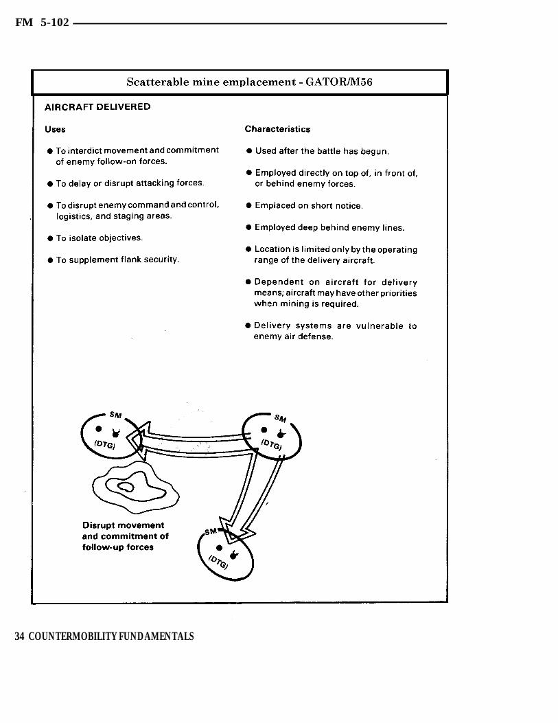
FM 5-102
34 COUNTERMOBILITY FUNDAMENTALS

FM 5-102
Mines are used extensively where the existingobstacle structure is weak or nonexistent.They should also be used with other re-inforcing obstacles, such as tank ditches, tomake breaching and clearing more costlyand time-consuming to the enemy.
Since all scatterable minefield systemsprovide great flexibility to maneuvercommanders, there will be extensive demandsfor them. Commanders and engineers shouldplan and carefully assign priorities. Availablesystems must be used for the most criticalneeds. Employment must be closely co-ordinated with obstacle plans, fires, and thescheme of maneuver. Coordination with firesupport planners, aviation staff officers, andair liaison officers is essential to insure priorplanning to execute minefield emplacementmissions on short notice. Planning andemployment of scatterable mines, as well asconventional mines, are discussed in depth inchapter 5.
CONTAMINATIONContamination can be either nuclear orchemical in nature. Both types are difficult topredict and control because they depend onwinds for placement, and are subject toweather and other environmental factors.The United States has renounced the first useof chemical weapons. Further, the mostpredictable source of nuclear contamination,Atomic Demolition Munitions (ADM), issubject to the same restrictions as all nuclearweapons and may not be available for usewhen needed. If an ADM is used for cratering,there will be both close-in radiation andfallout, each effectively contaminating anarea of reasonably predictable extent. Threatdoctrine considers the use of both nuclearand chemical weapons, and threat forcestrain for operations in contaminated areas.The presence of contamination and its effectson the battlefield must be anticipated.
COUNTERMOBILITY FUNDAMENTALS 35

FM 5-102
EXPEDIENT
The potential of expedient obstacles is almost form expedient abatis or strengthen woodedunlimited. They place a great premium on areas. The M9 Armored Combat Earthmoverimagination and ingenuity in the use of (ACE), dozers, loaders, and many other piecesavailable materials and other resources, thus of equipment can also be used.avoiding the logistic burden associated withall other types of obstacles. All sorts of The wreckage of destroyed towns, cities, ornonstandard log obstacles can be built. Their industrial areas offers a source of materialscomplexity depends upon the time andpersonnel available. Junked or destroyed carsand trucks or other debris can be spread toblock an open area or, if the region is rocky,earthmoving equipment can be used todistribute boulders to block tanks. Selectedtrees can be pushed over to make an abatis orto strengthen a wooded area where treespacing might otherwise allow armoredvehicles to pass. Short ditches can be cut inlieu of craters. Material can be pushed up toform a road block. Equipment can steepen ordeepen stream banks, gullies, or other breaksin the terrain to make expedient tank ditches.Trees can be cut or broken with a variety ofvehicles or pieces of equipment. They canalso be pushed or pulled down by winches to
to be used in making expedient obstacles. Ifpermitted, limited controlled flooding can beused, not only to inundate areas, but also tocreate soft or slippery areas where soilconditions would make this possible. Timberbridges can be burned, and controlled firescan be used to create obstacles in other ways.For example, igniting the brush in a brush-filled ditch, at the proper time, can make aneffective obstacle. If available, ice and snowcan be exploited to create effective obstacles.
By their nature, expedient obstacles sub-stitute locally available materials and soldierlabor for a logistical requirement. All that isneeded is the imagination to recognize thepotential of available materials.
36 COUNTERMOBILITY FUNDAMENTALS

FM 5-102
PRINCIPLES OF OBSTACLE EMPLOYMENT
AirLand Battle doctrine gives the commanderfighting the battle a complete range ofdefensive and offensive options. A static typedefense can be used to focus upon terrainretention using firepower from fixed positionsto deny terrain. The commander can alsodefend using a dynamic defense that focusesupon maneuver to destroy enemy forces ratherthan retain specific terrain.
The static and dynamic defensive frame-works are the extremes of the spectrum.Typically, the commander may choose tocombine both the static and dynamic formsin organizing the defense based upon thefactors of mission, enemy, terrain andweather, time, and troops (METT-T).
Whatever the concept, organizing the defensemust be carefully matched to the terrain. Theengineer is the principal element in re-inforcing the terrain to best complement themaneuver commander’s plan. The engineerand the maneuver commander must co-ordinate throughout the planning andbattlefield preparation sequence to insureunity of effort and maximum effectiveness ofobstacle employment.
Terrain reinforcement techniques must beemployed along the depth of the enemy’sformation and avenues of approach whereexisting terrain places him at the greatestdisadvantage. Use of reinforcing obstacles isthe principal method of terrain reinforcement.Reinforcing obstacles must be used inconjunction with the existing obstacles andthe commander’s plan. Reinforcing obstacleshave three primary purposes:
1 Enhance the effectiveness of friendlyantitank fires.
2 Delay the enemy’s advance, upset histiming, disrupt and channelize hisformations, and delay or destroy follow-onechelons.
3 Enhance friendly economy of forcemeasures.
Obstacles must be covered by fire if at allpossible. They should be located within theeffective range of friendly direct fire antitankweapons. Their locations must be carefullycoordinated with the location of battlepositions and direct and indirect weapons.We want to engage the enemy at themaximum effective range of our antitankweapons, and force him to breach and fighthis way through a series of obstacles whileunder intense fire. Each obstacle delays somepart of the enemy’s leading elements.
AN OBSTACLE CANSIGNIFICANTLY ENHANCE
ANTITANK FIRES.
The coordinated use of obstacles can delayand disrupt enemy formations, and also forcethem into the primary fields of fire of ourtanks and other antitank weapon systems, orprevent escape from such an engagementarea. The enemy is forced to move on thebattlefield in conformance with the friendlycommander’s plan.
COORDINATED OBSTACLESDELAY, DIVERT, CANALIZE,
AND DESTROY THEENGAGED ENEMY AND
FOLLOW-ON ECHELONS.
The skillful use of obstacles to channelize theenemy is a vital factor. Once the enemy forcemaneuvers into the engagement area, it isheld there by other groups of obstacles, andstill others may be used to close the trapbehind it. (Scatterable mines are ideal for thelatter purpose.) Other obstacles are used toseparate the enemy’s leading elements fromreserves or following echelons, thus pre-cluding reinforcement.
COUNTERMOBILITY FUNDAMENTALS 37

FM 5-102
Mutually supporting obstacles serve otherimportant purposes. They can be used in theeconomy of force role to strengthen anaturally strong existing obstacle area sothat it need only be lightly defended, thusfreeing forces to be concentrated elsewhere.Similarity, obstacles can be used in con-junction with mobile forces to protect flanks and other lightly defended areas. This is aparticularly important role in view of thethreat doctrine of penetration and envelop-ment, and the overall dispersion of forces onthe battlefield.
2
Regardless of the type defense employed bythe tactical commander, there are five basicemployment principles for reinforcingobstacles:
1 Reinforcing obstacles support themaneuver commander’s plan.
2 Reinforcing obstacles are integrated withobserved fires.
3 Reinforcing obstacles are integrated withexisting obstacles and with other rein-forcing obstacles.
4 Reinforcing obstacles are employed indepth.
5 Reinforcing obstacles are employed forsurprise.
1 Reinforcing obstacles support the ma-neuver commander’s plan. Reinforcing
obstacles must be planned and emplaced tosupport the tactical plan. Obstacles otherthan mines emplaced outside the range offriendly weapons are of little use. Reinforcingobstacles that do not accomplish one or moreof the basic purposes of reinforcing obstaclesare also of little value. Engineers must becompletely familiar with the tactical plan,the existing terrain, and the maneuvercommander’s intentions. Only then can full
advantage of the multiplier value of in-tegrating obstacles and fires be realized.
Reinforcing obstacles are integratedwith observed fires. Obstacles are used
to develop engagement areas in which enemymaneuver is restricted and slowed, therebyincreasing the hit probability of friendlydirect and indirect fires. The tacticalcommander and the engineer site the weaponsand obstacles which offer the best relativeadvantage, and consider terrain con-figuration and the effective weapons range.Special attention must be given to locatingobstacles to complement the fires of Dragon,tanks, and tube-launched, optically tracked,wire-guided missiles (TOWs). Since TOWshave a greater maximum effective rangethan Threat tanks, it is to our distinctadvantage to site part of the tactical obstaclesystem to capitalize on that difference.Generally, the greatest relative advantageaccrues when the obstacle is at the maximumrange possible and consistent with visibilityconditions and the tactical plan. Observedindirect fires are also used in conjunctionwith obstacles against enemy vehicles andinfantry out in the open. Observation andadjustment of fires are essential if the fulladvantage is to be developed. At the sametime, fires serve to protect the obstacle bymaking it costly to breach or bypass. Withrare exceptions, obstacles that are not coveredby fire are little more than a nuisance to theenemy’s leading elements.
Keep in mind, however, that the principalpurpose of integrating obstacle locations withfire is to enhance the effectiveness of thosefires—a significant combat multiplier effectof obstacle use.
3 Reinforcing obstacles are integratedwith existing obstacles and with
other reinforcing obstacles. Reinforcingobstacles are sited to take the maximumadvantage of existing obstacles. They are
38 COUNTERMOBILITY FUNDAMENTALS

FM 5-102
COUNTERMOBILITY FUNDAMENTALS 39

FM 5-102
placed where they can close the gaps oropenings between existing obstacles andiorclose any passages through them. The roadnetwork must be destroyed and the inherentnatural pattern of cross-country movementshould be disrupted. The first obstaclesplanned are bridge demolitions, road craters,abatis, and point or small minefield that tietogether the existing obstacle areas and closethe passages through them. Other reinforcingobstacles are then located to strengthen andextend the existing obstacle areas and blockmajor corridors. Taking advantage of theexisting obstacles reduces the resourcesrequired to quickly obtain an effectiveobstacle system. Effective reinforcement ofexisting obstacles also enhances economy offorce operations by permitting friendly forcesto concentrate on more trafficable terrainapproaches.
Individual obstacles must be sited anddesigned to tie in with existing obstacles orwith each other. An obstacle that can bebypassed immediately is worthless. Eachindividual obstacle must be carefullydesigned for the exact location it will occupy,and must overlap on each side with theexisting obstacle it will complete. The criticaldesign width of an obstacle is the distancefrom an existing obstacle to another existingobstacle (or to another reinforcing obstacle),and not the width of a road or highwaythrough the existing obstacle.
Another major design consideration is thatthe reinforcing obstacle does not need to bestronger than the integrated existing ob-stacle. The obstacle should be no moredifficult to breach than it is to get around. Ifthe enemy could force his way through the
40 COUNTERMOBILITY FUNDAMENTALS

FM 5-102
existing obstacle in the immediate vicinity in10 minutes, it would be wasteful to constructa reinforcing obstacle requiring 40 minutes tobreach. The effort and resources used toobtain the last 30 minutes of breaching timeare desperately needed elsewhere. Althoughthe delay or breaching time associated with aparticular obstacle may be difficult todetermine, this principle must neverthelessbe kept in mind to obtain the most use ofavailable resources.
Reinforcing obstacles are integrated witheach other to assure that probable bypassroutes are closed. For example, destruction ofa major highway through a wooded area islargely ineffective if any nearby road oropening that offers a ready bypass route isleft open. (Such destruction could be highlyeffective, however, if friendly forces wereseeking to divert the enemy along that bypassroute.) Reinforcing obstacles can also be usedto close gaps and lanes in other reinforcingobstacles. For example, a crater can be usedto close a road left open through a minefieldwhen all friendly troops have cleared.
5
4 Reinforcing obstacles are employed indepth. A series of simple obstacles ar-
ranged one behind the other along a probableaxis of enemy advance is far more effectivethan one large, elaborate obstacle. Restrictingthe design of obstacles to correspond with thestrength of the existing obstacle (as pre-viously discussed) helps to conserve effortand direct it toward executing obstacles indepth. Obstacles must not be located too closetogether so only a single enemy response isrequired. They must be far enough apart thateach will require a new deployment of theenemy’s counterobstacle forces and/orequipment. The distance between obstacleswill depend on the terrain and the obstacleeffort available. Proper use of obstacles indepth wears the enemy down and signifi-cantly increases the overall delay. At eachnew obstacle, he incurs losses and is forced to
stop and react. This wearing down effect ispsychologically significant. The desired effectis to degrade the enemy soldier’s will andinduce a feeling of hopelessness. This can bedone by convincing him that, beyond eachnew obstacle (with its attendant loss ofpersonnel and equipment), there awaitsanother obstacle with a similar cost; and,beyond that one, yet another, and so on.Another reason for using a greater number ofless elaborate obstacles is that each oneforces the enemy to expose his limitedcounterobstacle equipment and troops to loss.When the counterobstacle resources initiallyallotted to the leading elements have beendestroyed, the enemy’s movement will beseverely slowed until new counterobstacleunits can be brought forward.
Reinforcing obstacles are employed forsurprise. Using obstacles soasto obtain
surprise is one means available to thecommander to retain a degree of initiativeeven when defending. Scatterable minespermit rapid mining anywhere in the battlearea, confronting the attacker with acompletely new situation almost instantly.The self-destruct feature of the scatterablemine also provides surprise—a friendlycounterattack may be launched through anarea that was mined prior to the attack butwhere the mines have just self-destructed.
More conventional ways to obtain surpriseare also available and should be used. Theyinclude the sudden detonation of concealedobstacles in front of the attacking enemy orwithin his formations. Conventional waysalso include the use of phony obstacles tomislead the enemy as to the pattern andextent of the friendly obstacle system. Anobvious pattern of obstacles would divulgelocations of units and weapons. Friendlyforces must avoid readily discernible,repetitive patterns. By varying the type,design, and location, the enemy’s under-standing and breaching of our obstacle
COUNTERMOBILITY FUNDAMENTALS 41
FM 5-102
system is made more difficult. Extensive use designed and emplaced to support theof obstacles can make a major contribution to maneuver plan, are an effective “combatthis effort. multiplier.” Tactical commanders and
engineers must exploit the full value ofReinforcing obstacles which complement the obstacles.existing obstacle value of the terrain, and are
SUMMARY
Obstacles are classified as either existing orreinforcing. Existing obstacles are thosenatural and cultural restrictions to movementthat are a part of the terrain when battleplanning begins. The ability to recognize andevaluate the obstacle potential of the terrainis critical to planning the battle. Rein-forcing obstacles are constructed, emplaced,or detonated to knit together, strengthen, andextend exisiting obstacles.
Reinforcing obstacles must be integrated withfriendly observed fires, the friendly com-mander’s maneuver plan for both the enemyand friendly forces, and existing and re-inforcing obstacles. Reinforcing obstaclesmust also be arrayed in depth and employedfor surprise.
Mines are generally the most effective type ofobstacle because they also inflict losses onthe enemy, and their use is highly flexible.The Family of Scatterable Mines (FASCAM)vastly increases this flexibility, making thecreation of rapid minefield possible.
Obstacles are also used to delay and disruptan attacking force, upset the enemy’s timingand plans, and divert him into engagementareas and be destroyed. Obstacles can delayor destroy follow-on echelons.
Obstacles can significantly enhance theeffectiveness of our fires and thus our abilityto win the battle.
42 COUNTERMOBILITY FUNDAMENTALS

Chapter 3COMMAND AND CONTROL
C ountermobility activities are planned and executed todefeat the enemy’s ability to maneuver. This chapteraddresses the coordinated development of obstacle plans at
various levels of responsibility. Procedures for positive control ofreserve obstacles and preparation of demolition orders are alsoincluded.
LEVELS OF RESPONSIBILITY 44
RESERVE OBSTACLES 47
SUMMARY 53
COMMAND AND CONTROL 43

FM 5-102
LEVELS OF RESPONSIBILITYAn effective command and control system isa must for countermobility activities. Theprimary goal is to make the enemy go wherewe want, when we want, at speeds we dictate.We want to accomplish that goal with little orno effect on the ability of friendly forces tomove and maneuver. To do so requires acommand and control system that em-phasizes long-range planning, centralizedcontrol, and decentralized execution.Centralized control is necessary in theplanning of countermobility activities toinsure that the obstacle plan is integratedwith and supports the overall tactical plan.Senior command levels must dictate obstaclezones, obstacle-free areas, and reserveobstacles in the planning process. The specifictype and placement of those ground obstaclesare best accomplished by the level that canactually conduct a ground reconnaissance.
CORPS OBSTACLE PLANCentralized control of countermobility ac-tivities normally begins at the corps levelwith the corps obstacle plan. The corpsobstacle plan is general in nature andconcerned with the employment of obstaclesas a part of a specific tactical operation. Theobstacle plan supports the corps commander’sconcept of the operation and integrates theterrain aspects of the operation with thetactical plan. Through the allocation ofengineer support and logistics, the corpscommander shapes the countermobilityefforts of the division by weighting thoseareas viewed as most critical. The corpsobstacle plan provides a framework for thedivision plans. The corps obstacle plan canand will normally include the following items:
Assignment of areas of responsibility.
Designation of any specific obstacles vitalto the corps as a whole.
Completion times for all or any portion ofthe obstacle plan when deemed necessary;
however, completion times can be specifiedlater.
Gaps, lanes, and important routes to bekept open and areas important to thecommander for tactical and combat servicesupport operations, as well as for futureoperations. Gaps and lanes are specificallydesignated at the lowest level practicablein consonance with the mission of thecommand.
Allocation of engineer support, materials,transportation, and equipment.
Reporting instructions to insure allheadquarters in the chain of commandkeep abreast of the obstacle situation andplan their operation accordingly. As aminimum, reports to division level mustinclude target or obstacle identification,location, and status.
Coordination required between adjacentunits to insure critical points (such ascommon boundaries) are effectivelycovered, gaps and lanes are properlylocated, sufficient in number, and notclosed for passage before the time required.
Procedures for employment of scatterablemines to include provisions for air andartillery delivery, if not specified bystanding operating procedure (SOP).
Limitations or restrictions on the em-ployment of certain reinforcing obstaclessuch as minefield and booby traps,chemical contamination, and ADM. Toguard against premature execution, re-strictions may be placed on the em-ployment of reinforcing obstacles. Thecorps may accomplish this by requiringsubordinate units to request approval forthe closure of specific gaps and lanes. Thecorps may also retain approval authorityfor clearance or release of control over
44 COMMAND AND CONTROL
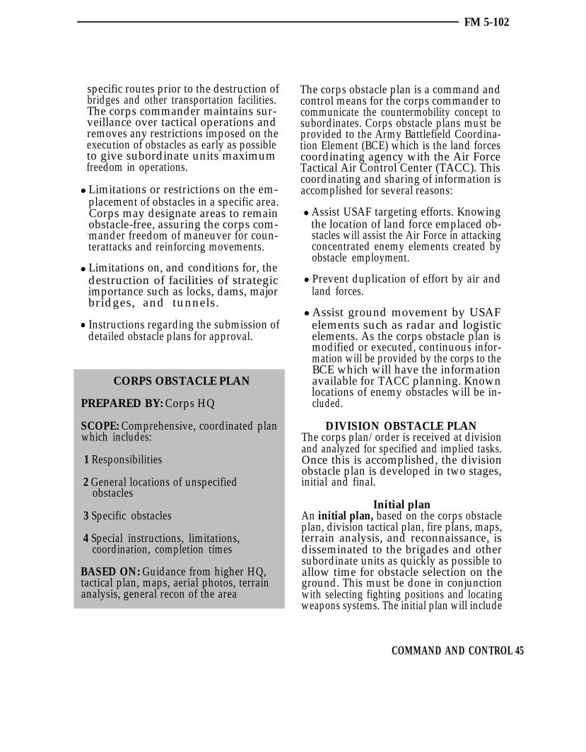
FM 5-102
specific routes prior to the destruction ofbridges and other transportation facilities.The corps commander maintains sur-veillance over tactical operations andremoves any restrictions imposed on theexecution of obstacles as early as possibleto give subordinate units maximumfreedom in operations.
Limitations or restrictions on the em-placement of obstacles in a specific area.Corps may designate areas to remainobstacle-free, assuring the corps com-mander freedom of maneuver for coun-terattacks and reinforcing movements.
Limitations on, and conditions for, thedestruction of facilities of strategicimportance such as locks, dams, majorbridges, and tunnels.
Instructions regarding the submission ofdetailed obstacle plans for approval.
CORPS OBSTACLE PLAN
PREPARED BY: Corps HQ
SCOPE: Comprehensive, coordinated planwhich includes:
1 Responsibilities
2 General locations of unspecifiedobstacles
3 Specific obstacles
4 Special instructions, limitations,coordination, completion times
BASED ON: Guidance from higher HQ,tactical plan, maps, aerial photos, terrainanalysis, general recon of the area
The corps obstacle plan is a command andcontrol means for the corps commander tocommunicate the countermobility concept tosubordinates. Corps obstacle plans must beprovided to the Army Battlefield Coordina-tion Element (BCE) which is the land forcescoordinating agency with the Air ForceTactical Air Control Center (TACC). Thiscoordinating and sharing of information isaccomplished for several reasons:
Assist USAF targeting efforts. Knowingthe location of land force emplaced ob-stacles will assist the Air Force in attackingconcentrated enemy elements created byobstacle employment.
Prevent duplication of effort by air andland forces.
Assist ground movement by USAFelements such as radar and logisticelements. As the corps obstacle plan ismodified or executed, continuous infor-mation will be provided by the corps to theBCE which will have the informationavailable for TACC planning. Knownlocations of enemy obstacles will be in-cluded.
DIVISION OBSTACLE PLANThe corps plan/order is received at divisionand analyzed for specified and implied tasks.Once this is accomplished, the divisionobstacle plan is developed in two stages,initial and final.
Initial planAn initial plan, based on the corps obstacleplan, division tactical plan, fire plans, maps,terrain analysis, and reconnaissance, isdisseminated to the brigades and othersubordinate units as quickly as possible toallow time for obstacle selection on theground. This must be done in conjunctionwith selecting fighting positions and locatingweapons systems. The initial plan will include
COMMAND AND CONTROL 45

FM 5-102
an overlay showing, as a minimum, targetsdirected by corps or higher headquarters andobstacles of such importance as to be specifiedby division. The plan may also specifyobstacle zones to be developed by designatedunit(s). In addition, the plan will assign
DIVISION OBSTACLE PLAN
PREPARED BY: Division HQ
INITIAL SCOPE:
1 Concept and detailed guidance
2 Specific obstacles directed by corps ordivision, responsibilities, and obstaclepriorities
BASED ON: Corps obstacle plan, divisiontactical plan, fire plans, maps, aerialphotos, and general recon of the sector
FINAL SCOPE: Completes the cycle.Specifically identifies each obstacle in thedivision obstacle system to include:
1 Target type
2 Target number
3 Coordinates
4 Priority
5 Completion date/time
6 Responsible unit
7 Special instructions (executiontimes/authority)
UPDATE BASED ON: Brigade plans andinput from other units following groundrecon and obstacle selection
responsibilities and, where necessary,priorities; allocate obstacle materials toinclude scatterable mines; and generallyinclude as much of the information describedfor the corps plan in whatever availabledetail as appropriate.
Final planAfter the brigades develop their obstacleplans in detail, and other units developassigned portions of the division obstacleplan by selecting individual obstacles, thesesubordinate plans are then incorporated bydivision with the initial plan to produce thefinal plan. The plan will normally be issuedas an annex to the division operations order.
When time is extremely limited, the divisionplan may never develop beyond the initialconcept plan. Conversely, when adequatetime is available, the division plan will besubmitted to corps and may be incorporatedinto a republished corps obstacle plan. Thecomplete division obstacle plan should hot becarried forward of division headquartersbecause of the danger of compromise. Divi-sion provides each brigade with extracts ofthe detailed plan to include pertinent portionsof the plans of adjacent brigades.
BRIGADE OBSTACLE PLANBrigades and comparable units develop adetailed obstacle plan, within the guidanceprovided by division, based on their tacticalplans and detailed terrain reconnaissance.To be effective, obstacle plans must beintegrated at maneuver unit level. Thisprocess is described in chapter 4. If combat isimminent, preparation of obstacles beginsimmediately without waiting for approval ofthe obstacle plan. Obstacle construction andobstacle plan development continue con- currently. Final brigade obstacle plansinclude:
Location and type of each obstacle,including those specified by higherheadquarters.
46 COMMAND AND CONTROL
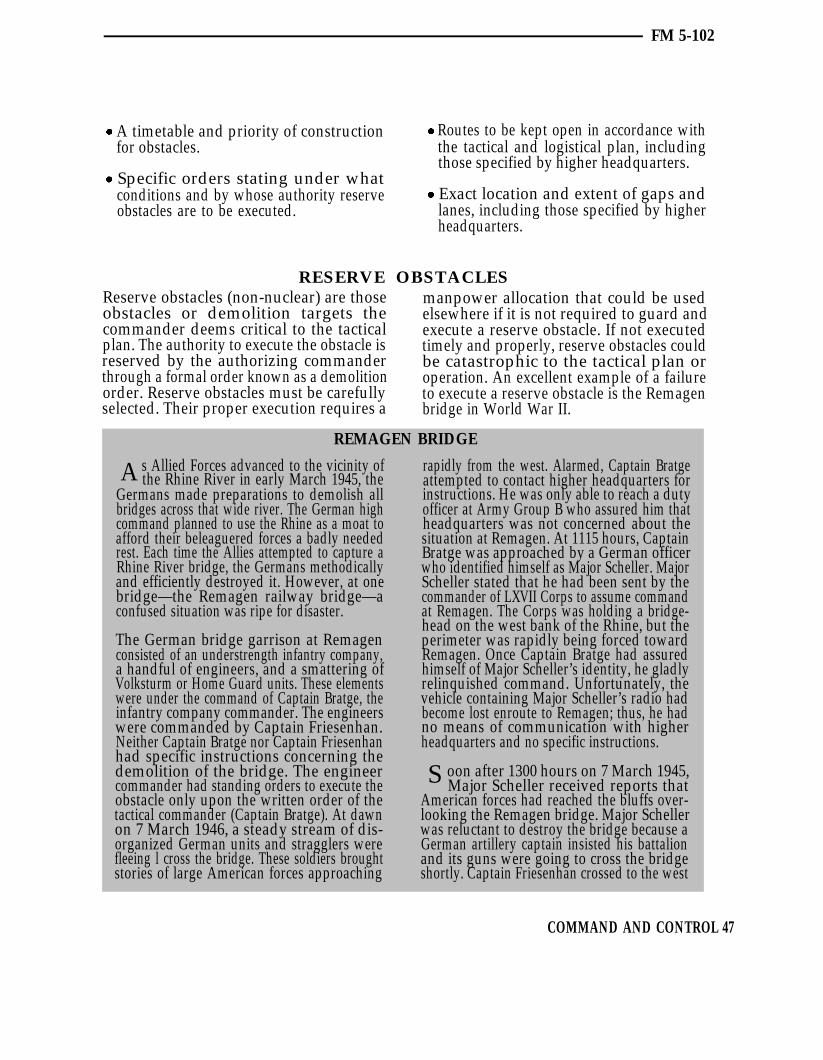
FM 5-102
A timetable and priority of construction Routes to be kept open in accordance withfor obstacles. the tactical and logistical plan, including
those specified by higher headquarters.Specific orders stating under whatconditions and by whose authority reserve Exact location and extent of gaps andobstacles are to be executed. lanes, including those specified by higher
headquarters.
RESERVE OBSTACLESReserve obstacles (non-nuclear) are thoseobstacles or demolition targets thecommander deems critical to the tacticalplan. The authority to execute the obstacle isreserved by the authorizing commanderthrough a formal order known as a demolitionorder. Reserve obstacles must be carefullyselected. Their proper execution requires a
A s Allied Forces advanced to the vicinity ofthe Rhine River in early March 1945, the
Germans made preparations to demolish allbridges across that wide river. The German highcommand planned to use the Rhine as a moat toafford their beleaguered forces a badly neededrest. Each time the Allies attempted to capture aRhine River bridge, the Germans methodicallyand efficiently destroyed it. However, at onebridge—the Remagen railway bridge—aconfused situation was ripe for disaster.
The German bridge garrison at Remagenconsisted of an understrength infantry company,a handful of engineers, and a smattering ofVolksturm or Home Guard units. These elementswere under the command of Captain Bratge, theinfantry company commander. The engineerswere commanded by Captain Friesenhan.Neither Captain Bratge nor Captain Friesenhanhad specific instructions concerning thedemolition of the bridge. The engineercommander had standing orders to execute theobstacle only upon the written order of thetactical commander (Captain Bratge). At dawnon 7 March 1946, a steady stream of dis-organized German units and stragglers werefleeing l cross the bridge. These soldiers broughtstories of large American forces approaching
manpower allocation that could be usedelsewhere if it is not required to guard andexecute a reserve obstacle. If not executedtimely and properly, reserve obstacles couldbe catastrophic to the tactical plan oroperation. An excellent example of a failureto execute a reserve obstacle is the Remagenbridge in World War II.
REMAGEN BRIDGE
rapidly from the west. Alarmed, Captain Bratgeattempted to contact higher headquarters forinstructions. He was only able to reach a dutyofficer at Army Group B who assured him thatheadquarters was not concerned about thesituation at Remagen. At 1115 hours, CaptainBratge was approached by a German officerwho identified himself as Major Scheller. MajorScheller stated that he had been sent by thecommander of LXVII Corps to assume commandat Remagen. The Corps was holding a bridge-head on the west bank of the Rhine, but theperimeter was rapidly being forced towardRemagen. Once Captain Bratge had assuredhimself of Major Scheller’s identity, he gladlyrelinquished command. Unfortunately, thevehicle containing Major Scheller’s radio hadbecome lost enroute to Remagen; thus, he hadno means of communication with higherheadquarters and no specific instructions.
oon after 1300 hours on 7 March 1945,Major Scheller received reports that
American forces had reached the bluffs over-looking the Remagen bridge. Major Schellerwas reluctant to destroy the bridge because aGerman artillery captain insisted his battalionand its guns were going to cross the bridgeshortly. Captain Friesenhan crossed to the west
S
COMMAND AND CONTROL 47

FM 5-102
end of the bridge. He planned to execute a craterwhich had been emplaced some months beforeto prevent tanks from rapidly reaching thebridge. Around 1600 hours. a company ofAmerican infantry and tanks appeared at theapproaches to the bridge. On his own authority,Captain Friesenhan fired the crater, then racedacross the bridge to find Captain Bratge andMajor Scheller to get the order to blow thebridge. Enroute, he was knocked senseless by aconcussion from a tank shell. Fifteen minutespassed before he regained consciousness,continued across the bridge, and obtainedapproval to fire the demolition. Initially, CaptainFriesenhan insisted on written orders, but thenrelented in the interest of time.
Captain Friesenhan turned the key to electricallyfire the charge, but nothing happened. He triedagain and again with no results. He realized that
Some obviously glaring errors which provedextremely costly to the German Armyincluded:
Insufficient guard force.
Inadequate communication.
Confused instruction on when and onwhose order the bridge was to be blown.
EXECUTION OFRESERVE OBSTACLES
A reserve obstacle must have positive writteninformation and instruction on the followingitems:
Who is the authorizing commander?
Who, if anyone, is to guard the obstacleuntil it is executed?
Who prepares and executes the obstacle?
Under what circumstances is the obstacleto be executed?
the firing circuit was broken. By this time,American machine gun fire and tank fire weresweeping the bridge. Repairs to the circuit wereout of the question. A sergeant volunteered togo out on the bridge and fire an emergencycharge nonelectrically. The sergeant dashed outon the bridge, and returned on the run minuteslater. The charges exploded, but when the dustsettled, the bridge still stood. American FirstLieutenant Karl H. Timmerman, commander ofA Company, 27th Armored Infantry Battalion,and his soldiers rushed across the bridge. Theyestablished the beginnings of a bridgeheadwhich would enable US forces to transport8,000 soldiers, including one tank battalion,across the Rhine in the next 24 hours. CaptainFriesenhan and Captain Bratge were captured.Major Scheller and three other officers weretried by a German military tribunal, and wereexecuted by a firing squad.
There are three primary players involved inthe proper and timely execution of reserveobstacles; namely, the authorizing com-mander, the demolition guard commander,and the demolition firing party commander.
Authorizing commanderThe authorizing commander has overallresponsibility. The authorizing commandermay be a corps, division, brigade, or anyother commander who deems that a particulartarget or obstacle is so critical to the tacticalplan that its preparation, protection, andexecution upon order are insured.
Demolition guard commanderThe demolition guard commander is the on-site commander who takes orders from theauthorizing commander and who is re-sponsible for the successful execution of thereserve obstacle. The demolition guardcommander is also responsible for security,preparing the obstacle, and giving the orderto arm and execute the obstacle once theauthority to execute has been received.
48 COMMAND AND CONTROL
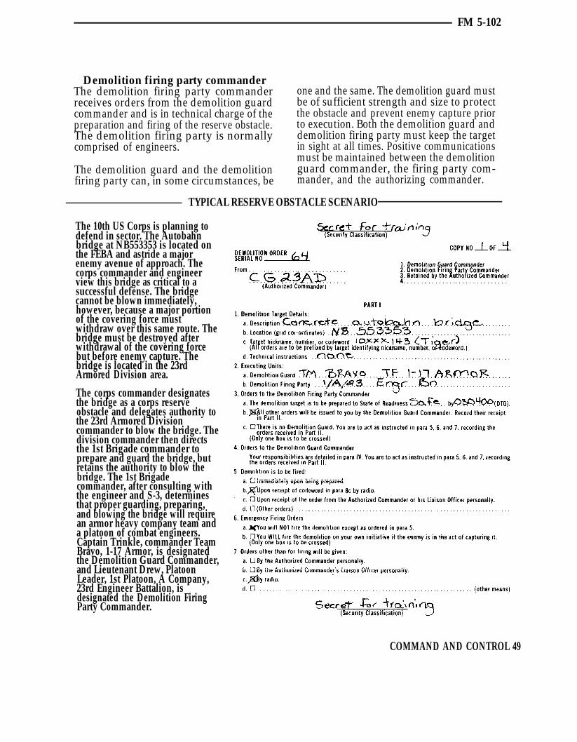
FM 5-102
Demolition firing party commanderThe demolition firing party commander one and the same. The demolition guard mustreceives orders from the demolition guard be of sufficient strength and size to protectcommander and is in technical charge of the the obstacle and prevent enemy capture priorpreparation and firing of the reserve obstacle. to execution. Both the demolition guard andThe demolition firing party is normally demolition firing party must keep the targetcomprised of engineers. in sight at all times. Positive communications
must be maintained between the demolitionThe demolition guard and the demolition guard commander, the firing party com-firing party can, in some circumstances, be mander, and the authorizing commander.
TYPICAL RESERVE OBSTACLE SCENARIO
The 10th US Corps is planning todefend in sector. The Autobahnbridge at NB553353 is located onthe FEBA and astride a majorenemy avenue of approach. Thecorps commander and engineerview this bridge as critical to asuccessful defense. The bridgecannot be blown immediately,however, because a major portionof the covering force mustwithdraw over this same route. Thebridge must be destroyed afterwithdrawal of the covering forcebut before enemy capture. Thebridge is located in the 23rdArmored Division area.
The corps commander designatesthe bridge as a corps reserveobstacle and delegates authority tothe 23rd Armored Divisioncommander to blow the bridge. Thedivision commander then directsthe 1st Brigade commander toprepare and guard the bridge, butretains the authority to blow thebridge. The 1st Brigadecommander, after consulting withthe engineer and S-3, determinesthat proper guarding, preparing,and blowing the bridge will requirean armor heavy company team anda platoon of combat engineers.Captain Trinkle, commander TeamBravo, 1-17 Armor, is designatedthe Demolition Guard Commander,and Lieutenant Drew, PlatoonLeader, 1st Platoon, A Company,23rd Engineer Battalion, isdesignated the Demolition FiringParty Commander.
COMMAND AND CONTROL 49

FM 5-102
Upon arriving at the bridge, TeamBravo occupied defensive positionsoverlooking the bridge. Theengineer platoon began areconnaissance of the bridge. Notechnical directions were given tothe platoon regarding the extent ofdestruction required. A radio callwas made to the brigade S-3 wholater replied that two spans on thenear shore were to be dropped.Those changes were recorded inpart 12 of the demolition order.
The charges were placed and thefiring point was collocated with theTeam Bravo command post whichprovided a good vantage point tothe bridge. Checks were maderegularly to insure positivecommunications. Seniority listswere established for the demolitionguard and the demolition firingparty. For the next three days, thebridge was secured by thedemolition guard, and the firingparty regularly checked thedemolitions and firing systems.
50 COMMAND AND CONTROL

FM 5-102
At first light on 4 October,elements of the covering forcebegan crossing the bridge. Later inthe morning, smoke and artilleryfire assisted the remainder of thecovering force in making a cleanbreak with the enemy and crossingthe bridge. Code word “apple” wasreceived and the system waschanged from safe to armed. Codeword “orange” was received andauthenticated, and Captain Trinkleinformed Lieutenant Drew to blowthe bridge NOW. The bridge wasblown and denied to the enemy. Asthe sequence unfolded, theappropriate blocks of thedemolition order were completed.The mission was successfullyaccomplished by following theorders to the letter.
COMMAND AND CONTROL 51
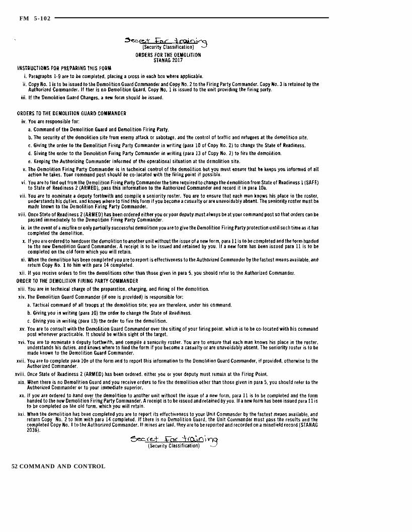
FM 5-102
52 COMMAND AND CONTROL
FM 5-102
SUMMARY
The obstacle plans and updates are theprincipal command and control vehicles forobstacles planned and emplaced before thebattle begins and during its early stages,Further employment of obstacles will be basedon enemy movement and designed to fit aparticular tactical situation. Responsivecommunication, timely intelligence, and rapiddecision making are keys to successful
obstacle employment after the battle hasbegun.
Reserve obstacles can be vital to an operation.They must be planned and executed carefully.The number of reserve obstacles should beheld to the absolute minumum due to theassets required to insure that they are guardedand executed properly.
COMMAND AND CONTROL 53
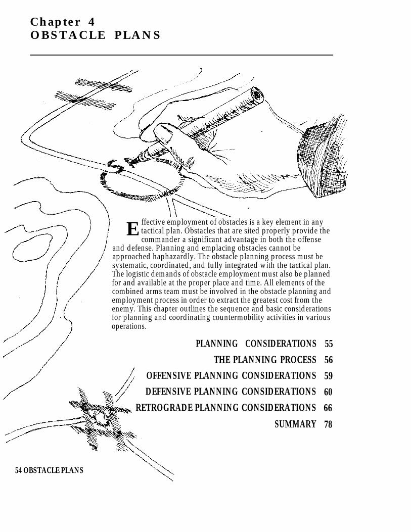
Chapter 4OBSTACLE PLANS
E ffective employment of obstacles is a key element in anytactical plan. Obstacles that are sited properly provide thecommander a significant advantage in both the offense
and defense. Planning and emplacing obstacles cannot beapproached haphazardly. The obstacle planning process must besystematic, coordinated, and fully integrated with the tactical plan.The logistic demands of obstacle employment must also be plannedfor and available at the proper place and time. All elements of thecombined arms team must be involved in the obstacle planning andemployment process in order to extract the greatest cost from theenemy. This chapter outlines the sequence and basic considerationsfor planning and coordinating countermobility activities in variousoperations.
PLANNING CONSIDERATIONS
THE PLANNING PROCESSOFFENSIVE PLANNING CONSIDERATIONS
DEFENSIVE PLANNING CONSIDERATIONS
RETROGRADE PLANNING CONSIDERATIONS
SUMMARY
55
56
59
60
66
78
54 OBSTACLE PLANS

FM 5-102
PLANNING CONSIDERATIONS
Obstacle planning is serious business, andinvolves all elements of the combined armsteam. Obstacles must support present andfuture tactical plans, be logistically sup-portable, and fully coordinated. Someimportant factors to be considered are listedbelow.
MISSIONThe mission is the primary consideration inobstacle planning. The employment of ob-stacles in support of a DEFEND missionwould be significantly different from obstacleemployment in support of a DELAY or anoffensive mission. The obstacle plan shouldbe tailored to support the mission of theorganization and accomplish the objectivesof the command.
DIRECTED ANDRESERVE OBSTACLES
Directed and reserve obstacles are of primeimportance to the overall mission and shouldbe planned first. Authority and time ofexecution must be known.
FUTURE PLANSWhile obstacle employment is supporting thecurrent mission, it should not impede futureplans or missions. This may not be completelypossible in every instance. Emplacing anartillery delivered minefield upon an at-tacking enemy may be the right thing to do,even though an attack through the area wasplanned prior to self-destruction of theminefield. Pros and cons must both beconsidered.
ENEMY STRENGTHSAND WEAKNESSES
The obstacle plan should exploit theweaknesses of the enemy. If the enemy isshort of rapid bridging capability, a tankditch may be a more effective obstacle than aminefield. If the enemy is low on diesel fuel orammunition, attacking their trains andsupply lines may be the most effective use ofobstacles such as scatterable mines.
TERRAIN AND WEATHERThese factors and their effects are critical inanswering the following questions: Whereare good existing obstacles? Are they withinthe enemy’s avenue of approach? Are theyeffective when tied in with reinforcingobstacles? Are they within range and fieldsof fire of friendly weapons? What are theanticipated weather conditions? Is the soilfrozen? Is digging possible? Can mines beburied?
AVAILABLE TIME, MATERIALS,MANPOWER, AND EQUIPMENT
Answers to these questions will dictate to alarge degree the type and extent of the ob-stacle system, and also provide informationon additional resources required and taskorganization. How much time is available tospend on battlefield preparation? Have therequired materials been ordered? Are they onhand? Is the manpower available for labor-intensive obstacles? Is earthmoving equip-ment available for tank ditches and otherequipment-intensive obstacles? Has the highdiesel fuel consumption rate been plannedfor?
EFFECTS ON THELOCAL POPULATION
Cultural features are not destroyed unless themission makes it absolutely necessary. Theseconsiderations are not inclusive. There maybe many other important factors. Eachmission, operation, or battle phase will posedistinct requirements that must be consideredand planned for. Obstacles can be thedifference between winning and losing. Theiremployment must be carefully planned andfully coordinated.
Obstacles should be emplaced according tothese general guidelines:
Obstacles should support weapon systemsby slowing the enemy at the maximumeffective ranges of our weapons ystems, aslimited by fields of fire available.
OBSTACLE PLANS 55

FM 5-102
Obstacles should not impede our own Obstacles are emplaced in as much depthmobility; or, if they do, they should be as is feasible after considering the time,reserved targets or scatterable mines with manpower, and logistical constraints.a self-destruct time coordinated to future These in-depth obstacles are integratedmaneuver plans. into the battle position fire support plans,
assist the commander in stopping theObstacles must hinder enemy movement, enemy within the MBA, and then assumeas we move from battle positions. the offense.
THE PLANNING PROCESSDeveloping an obstacle plan that is effectiveand supports the tactical plan requirescoordinated sequential planning. The fol-lowing sequence should be used to developsuch an obstacle plan. This sequence isequally effective in both offensive anddefensive operations.
1 Analyze the mission.
1
2 Analyze avenues of approach.
3 Analyze engagement areas,battle positions,and locations of weapon systems.
4 Determine possible obstaclelocations and types.
5 Determine the commander’sobstacle priorities.
6 Determine resources.
7 Determine actual worksequence.
8 Determine task organizationrequired.
9 Determine coordinationrequired.
Analyze the mission. The mission isa clear, concise statement and purpose of
the task to be accomplished by the command.It tells the command the “who,” “what,”“where,” and “when” of an operation.Analysis of the mission is a critical item inplanning obstacles. The “who” portion andaccompanying task organization allocatesresources to do the job. The “what” specifiesthe type operation such as “defend,” “attack,”or “delay.” “Where” outlines the area ofoperations, and “when” specifies the timeavailable and essentially establishes dead-lines. During the planning phase, much or allof this information will be verbal based uponcommander and staff analysis of the missionreceived from higher headquarters. Theestimate, eventual plan, and execution arebased upon tasks contained in the mission.
Analyze avenues of approach. Once themission has been received and analyzed
and the basic objectives are known, the nextstep in obstacle planning is to determineavenues of approach. Terrain analysistechniques and existing obstacle evaluation,as described in chapter 2, are performed. Thecommander must visualize the avenues ofapproach under all conditions, and determinethe size of friendly or enemy forces thoseavenues can support.
2
56 OBSTACLE PLANS
FM 5-102
3 Analyze engagement areas, battle po-sitions, and locations of weapon sys-
tems. A good terrain analysis will showwhere the best areas are for friendly weaponsto engage the enemy. In offensive planning,the most likely areas where friendly forcescould expect to be engaged by enemy directfire weapons can also be ascertained. Theanalysis process is essentially the same inboth the defense and the offense. Analysis ofexisting obstacle areas, fields of fire, andnatural cover and concealment are key factorsin determining where to best engage theenemy or expect to be engaged.
4 Determine possible obstacle locationsand types. Selection of engagement areas
and battle positions must be accomplishedprior to planning reinforcing obstacles. Oncethe commander has selected engagementareas and battle positions, then the com-mander and the engineer select those re-inforcing obstacles that accomplish the basicprinciples. This selection process is un-constrained, meaning that the commanderand engineer will select and site all thereinforcing obstacles necessary withoutregard for manpower, time, and logistics.This selection process will determine what“needs” to be done in order for the obstaclesystem to be most effective. What “needs” tobe done will usually require more effort thanresources available. The process provides thecommander and the engineer with a methodto establish priorities if resources areconstrained.
5 Determine the commander’s obstaclepriorities. Once the unconstrained obsta-
cle estimate has been accomplished, the com-mander can establish priorities for obstacles.By seeing what “needs” to be done, thecommander can choose those obstacles thatmust be emplaced. Through this process, the
engineer is given direction to employ re-sources knowing the effort is expended onthose obstacles most critical for accom-plishing the command’s objectives. The type,proposed location, and purpose of the ob-stacles will depend on an offensive ordefensive plan. However, the basic thoughtprocess remains constant.
6 Determine resources. The commanderand the engineer consider the assets avail-
able to construct, guard, and execute theobstacle plan. Engineer assets are limited,and the priority of work maybe given to onlya portion of the planned area of operations.The engineer takes the commander’s prior-ities and makes an estimate based upon time,manpower, equipment, and logistics. Theengineer must know how much of eachresource is required to emplace and execute agiven obstacle. This estimate is based upontype of obstacle, soldier experience, state oftraining, and condition of equipment.Standard obstacles (appendix D) may beused to assist in the estimating process. Theyare only a guide and should be alteredaccording to existing conditions at the timeof the estimate.
Another factor in the engineer estimate is thecommander’s decision on who will guard anddetonate preliminary demolition obstaclesnot detonated immediately after emplace-ment. Essentially, the commander has twochoices—either use engineer soldiers, orsoldiers from maneuver units. If engineersare used, then engineer assets are used upquickly, thus limiting the number of obstaclesthat can be emplaced as the battle progresses.The same can be said for using maneuverunits to guard and detonate obstacles. Thisdifficult decision must be made early enoughfor the engineers and maneuver units toproperly plan. In any case, the target turnover
OBSTACLE PLANS 57

FM 5-102
process must be trained and rehearsed duringcombined arms training so the commanderhas some latitude in decision making.
The time available to accomplish the obstaclemission is an important consideration. Leadtime is required to gain sufficient obstacledensity to obtain tangible benefits from theobstacle plan. Emplacement time will varywith the types of obstacles. For example, itmay take more manhours to emplace aconventional tactical minefield than toemplace a road crater or prepare a bridge fordemolition. Emplacement lead time is dividedinto two parts: time required to actuallyconstruct the obstacle, and time required toget materials to the obstacle location. Thelatter may require twice as much time asactual obstacle construction. The loss inproductivity due to logistics time can bereduced by allocating additional transpor-tation support to engineer units. In mostcases, the engineer squad’s truck or APCmust serve as both personnel carrier (mobility)and cargo carrier (resupply). Another way toinprease production is to work maximumhours, but this pace can be maintained foronly a few days before soldiers and equipmentbegin to fail.
Finally, logistical matters must be con-sidered. The commander must set prioritiesfor the delivery of munitions and material,and must allocate the available haul assetsamong ammunition, obstacle materials, andother critical supplies. Among obstaclematerials, difficult choices must be made. Aconventional tactical minefield can take upto a hundred times the haul assets of a pointobstacle, yet the minefield may be the onlyeffective obstacle in the situation. Tominimize the haul requirements, the engineermust make imaginative use of locallyavailable material. Alternative obstaclesshould also be considered. Frequently, tankditches can be substituted for a minefield,using engineer equipment that is availableand not in use, instead of placing an
additional demand on an overloadedtransportation system.
7 Determine actual work sequence. Thecommander and the engineer now must re-
consider the possible obstacles identifiedearlier. Considering the time available, workforce, and logistical assets, they identifythose obstacles which can realistically becompleted within the allotted time. They alsoidentify obstacle work which may continueduring the battle.
The commander’s obstacle plan will usuallydevelop through the answers to such ques-tions as:
Does the unit have 4 hours, 2 days, or 2weeks before the battle is expected?
What are the limits of obstacle logisticassets available?
IS the divisional engineer unit by itself oris it supplemented by corps engineers?
To what extent is the tactical commanderable to augment engineer units with othermembers of the combined arms team?
8 Determine task organization re-quired. The tactical commander and the
engineer must balance the comprehen-siveness of the obstacle plan with the realitiesof limited assets. For example, a task forcecommander’s sector may be critical and inneed of intensive engineer work in order tocomplete the plan. The brigade commander,on the other hand, may anticipate that theprimary threat will develop in another taskforce sector. Accordingly, the brigade com-mander may allocate fewer engineers thandesired by the task force commander. Theengineer recommends the allocation ofengineer units to best support the brigadecommander’s coordinated obstacle plan.Additional engineer units, if available, maybe obtained by coordination with the division
58 OBSTACLE PLANS

FM 5-102
engineer and the division commander. Theseunits may come from the organic engineerbattalion or corps assets.
Determine coordination required.9 Obstacle planning and employment re-
quires extensive coordination to accomplishits purpose. The G-4/S-4 must receive amaterials estimate as early as possible inorder to plan logistic support of the obstaclesystem.
The artillery fire support coordinator, avia-tion officer, and air liaison officer must alsobe consulted to integrate scatterable mineswith the obstacle system. Missions whichrequire scatterable mines are planned in
detail to include the location, the unitdelivering the mines, and necessary logisticsupport. Coordination and responsibilitiesfor scatterable mine employment are outlinedin chapter 5.
Obstacles must also be coordinated withfollow-on and adjacent units to insure thatthe location and extent of the obstacle systemare known. This coordination will precludethe obstacle impeding movement andmaneuver of friendly forces. If followed, thisplanning sequence is a workable, realistic,and coordinated approach to planning ob-stacle employment. It will insure that theresult is a coordinated and executable planthat extracts the greatest cost from the enemy.
OFFENSIVE PLANNING CONSIDERATIONS
In the offense, the priority of the engineereffort is to maintain friendly force mobility.Countermobility activities are also importantto halt or slow the enemy’s counterattackcapability and isolate the battlefield. Suchoperations assist friendly forces in defeatingthe enemy in detail. Countermobility opera-tions can be employed in all types of offensiveoperations. Obstacles and mine warfare inoffensive operations have three mainpurposes:
1 Prevent enemy enforcement.
2 Facilitate economy of force.
3 Provide security.
1 Prevent enemy reinforcement. Offen-sive operations are conducted to exploit
enemy weaknesses. To prevent the enemyfrom reinforcing weak areas under friendlyattack, critical routes should be interdicted tohinder movement of reserves and logistics.Speed and deep interdiction capabilities arevital, Air-delivered scatterable mines areideally suited for this mission.
2 Facilitate economy of force. Obstaclesand mines can be utilized in selected sec-
tors to allow defense by reduced forces. Re-lieved maneuver units can then be con-centrated in other sectors for the attack.Under other circumstances, easily defendedterrain which is reinforced with obstaclesand on-call scatterable mines may permitmajor sectors to be held by a relatively smallforce. Operations of this type are conductedby armored cavalry units with a screen or aprotection mission.
3 Provide security. Inoffensive operations,mines and obstacles may be emplaced
along the flanks of advancing forces incritical areas to halt or slow enemycounterattacks. In planning offensiveoperations, avenues of approach offeringnatural flank protection—such as a river or aridge line—should be carefully evaluated.During the advance, it may be possible toprotect a flank by destroying all bridgescrossing a river, or by interdicting all roadsand trails crossing a ridge line. Swamps,canals, lakes, forests, and escarpments are
OBSTACLE PLANS 59

FM 5-102
natural terrain features that can be quicklyreinforced for flank security.
During offensive operations, engineercountermobility plans must permit rapidemplacement and flexibility. Time and re-sources will not permit development of theterrain’s total defensive potential. Based uponlikely enemy reaction, the most probablecounterattack avenues should be closed offwith obstacles. Plans should be developed forother possibilities and resources committedwhen the enemy response becomes apparent.Scatterable mines are excellent for thispurpose. Aircraft and artillery deliveredscatterable mines could be preplanned oneach of several available routes. The minesshould be delivered in front of, on top of, or onthe flanks of the lead elements of an enemycounterattack after the enemy has committeditself to one of the routes. Rapid crateringdevices are another excellent capability.
Speed of countermobility operations is vitaland cannot be overemphasized. Engineersupport must keep up the pace and emplaceobstacles and mines along with advancingmaneuver forces. Effort for countermobilityduring offensive operations must be carefullyweighed against the mobility requirementsto support the advance. Resources must beplanned and used wisely. Under ideal cir-cumstances, plans should be flexible forengineer forces to perform both mobility and
countermobility operations as the tacticalbattlefield situation requires.
Control of mines and obstacles, and accuratereporting to all units are vital. An obstacle ormine in place will hinder either friendly orenemy maneuver. Positive command andcontrol is necessary to insure that minefieldand obstacles are not executed until desired.Once executed, they must be reported by theexecuting unit through operation channelsand posted to operational and intelligencemaps. Information on obstacles and mine-field in place is disseminated with tacticalintelligence. The recording and reportingprocedures for scatterable mines must berigidly followed. These procedures arediscussed in chapter 5. Key factors forcountermobility activities during offensiveoperations are:
Enemy situation and capabilities.
A good terrain analysis to determine wherefriendly forces are vulnerable to coun-terattack.
Speed of obstacle emplacement.
Preplanning and coordination.
Information flow to inform friendly forcesof friendly and enemy obstacle locations.
DEFENSIVE PLANNING CONSIDERATIONSPURPOSES OF THE DEFENSE
Defensive operations achieve one or more of Wear down enemy forces as a prelude tothe following: offensive operations.
Cause an enemy attack to fail. Control essential terrain.
Gain time. Retain tactical, strategic, or politicalobjectives.
Concentrate forces elsewhere.
60 OBSTACLE PLANS

FM 5-102
The immediate purpose of any defense is tocause an enemy attack to fail. The otherreasons listed contribute to purposes beyondthe immediate defense.
It may be necessary to gain time forreinforcements to arrive or to economizeforces in one sector while concentrating forcesfor attack in another. In either case, a defenseor a delay may achieve these purposes.
In some cases, a force may be defendingbecause it cannot attack. The defender thentakes advantage of position and superiorknowledge of the terrain. Once the enemy hasbeen committed to the defense and weakenedby losses, friendly forces maneuver to destroythe enemy with fires or counterattacks. Inother cases, portions of a force may be re-quired to retain key terrain or essentialtactical, strategic, or political objectives.
In some instances, these must be first seizedby airmobile or airborne forces, and then helduntil a larger force can link with the defender.An underlying purpose of all defensiveoperations is to create the opportunity tochange to the offensive. All activities of thedefense must contribute to that aim.
The defense has been called the strongerform of war because denying success to theenemy is easier than forcing the enemy to doour will. The defender has significant ad-vantages over the attacker. In most cases, theground is better known, and the defenderoccupies first and therefore becomes strongeras positions improve and forces mass. Oncethe battle begins, the defender fights fromcover against a more exposed enemy, anduses the terrain to mask movements as forcesgather to block and attack the enemy. Finally,the defender can postpone commitment ofmajor forces until the attack has developed,and then strike the extended enemy overcarefully selected and prepared terrain withinthe defensive area. The effects of obstacles,
airpower, and conventional weapons onexposed troops, and certain aspects of nu-clear, chemical, and electronic warfare, alsofavor the defender.
Balanced against the defender’s advantages,however, is the attacker’s single greatestasset—possession of the initiative. Theattacker takes advantage of the opportunitiesto concentrate first and surprise the defenderby chosing ground, direction of approach,and time of attack. Also, this initial ad-vantage is used to mislead or distract thedefender, slow recognition of the main attack,and delay implementation of counter-measures. The defender’s ultimate task is toovercome the attacker’s initial advantagesand quickly regain the initiative.
Napoleon summarized the requirements ofdefensive campaigns when he said in hisMemoirs: “The whole art of war consists in awell-reasoned and extremely circumspectdefensive, followed by rapid and audaciousattack.”
The key terms of AirLand Battle doctrine—initiative, depth, agility, and sychro-nization— also outline the requirements fora successful defense at any level.
InitiativeSeize the tactical initiative locally, thengenerally, as the battle progresses.
DepthFight the enemy throughout the depth of itsformations to delay and disorganize, and tocreate opportunities for offensive action. Thedefender must organize forces and resourcesin depth to gain the time and space requiredfor flexibility and responsive maneuver.
AgilitySet the terms of battle through flexible use offire, maneuver, and electronic warfare. Justas the attacker is committed to an action, the
160-337 0 - 94 - 3OBSTACLE PLANS 61
FM 5-102
defender changes the situation and therebyforces a different countermove. This over-loads the enemy’s command and controlsystem and renders his reaction un-coordinated and indecisive. Effective use ofagility can lead to the enemy’s piecemealdestruction.
SynchronizationSynchronize all available tools of battle in.well coordinated combat actions. Violentexecution of plans and aggressive ex-ploitation of enemy vulnerabilities can haltthe attacking force’s momentum.
Initially, the defender will be outnumbered.In the early stages of the battle, the defendermust capitalize on the advantage of fightingfrom stationary, protected positions to haltthe enemy. Deep attack on the enemy, theactions of security forces, and detailed fireand obstacle plans facilitate containment ofthe attack.
Once the attacker has been controlled andthe defender has concentrated forces in thearea of the main attack, the defender canthen operate against exposed and preciselylocated segments of the attacking force. Then,by being under the cover of his own fieldartillery, air defense, and on ground he hasreconnoitered and prepared, the defender hasthe advantage. Once the attacker has ex-tended into the defended area, he is vulnerableto fires from all sides, surprise attacks onflanks and rear, and loss of the initiative.
To succeed, the attacker must shatter thedefense quickly and maintain a high pace ofoperations to prevent its reconstitution. Todefeat the attacker, the defender must pro-tract operations, keep the tempo slow enoughto allow reaction, and, ultimately, isolate anddestroy attacking forces.
The attacker cannot be allowed to focus fullstrength at one time and place on thebattlefield before defensive countermeasures
have been prepared. This can be accom-plished through skillful use of terrain and byinterdiction of following forces through deepattack. The attacker’s ability to sustain themomentum of the attack and set the pace ofbattle must be broken. This will occur if it isdifficult to employ fire support assets,reinforce, resupply, and direct attackingechelons.
The attacker must be required to divertenergies and efforts into nonproductiveventures and to strike at nonexistent targetsthrough deception, operations security, andmaneuver. This dissipates strength and usesresources.
Karl von Clausewitz characterized the idealdefense as a “shield of blows.” At the onset,the defender yields the initiative to theattacker. However, the defender has theadvantages of prepared positioning and betterground knowledge, and uses them to slow themomentum of the attack and repeatedly strikethe enemy. In defeating the attackers’ com-bined arms coordination, strength, andconcentration, the defender destroys theattacking force with effective maneuversupported by flexible firepower. It is notnecessary to kill every enemy tank, squad, orcombat system, but only to destroy the abilityto continue fighting.
United States Army defensive doctrine isdesigned to be applicable anywhere in theworld. The form of defense the commanderchooses will depend on the mission, nature ofthe enemy, terrain possibilities, and capa-bilities of available units. The commandermay elect to defend well forward or inconsiderable depth, if not required to hold aspecified area or position. The commandermay even choose to preempt the enemy withspoiling attacks if conditions favor suchtactics. Depending on the depth available,forces at hand, and the mission, thecommander may defend by striking theenemy as it approaches. The commander
62 OBSTACLE PLANS
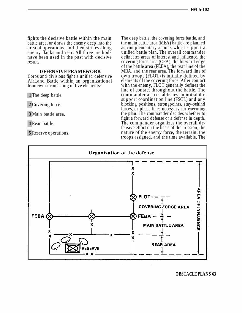
FM 5-102
fights the decisive battle within the mainbattle area, or draws the enemy deep into thearea of operations, and then strikes alongenemy flanks and rear. All three methodshave been used in the past with decisiveresults.
DEFENSIVE FRAMEWORKCorps and divisions fight a unified defensiveAirLand Battle within an organizationalframework consisting of five elements:
1 The deep battle.
2 Covering force.
3 Main battle area.
4 Rear battle.
5 Reserve operations.
The deep battle, the covering force battle, andthe main battle area (MBA) battle are plannedas complementary actions which support aunified battle plan. The overall commanderdelineates areas of interest and influence, thecovering force area (CFA), the forward edgeof the battle area (FEBA), the rear line of theMBA, and the rear area. The forward line ofown troops (FLOT) is initially defined byelements of the covering force. After contactwith the enemy, FLOT generally defines theline of contact throughout the battle. Thecommander also establishes an initial ilresupport coordination line (FSCL) and anyblocking positions, strongpoints, stay-behindforces, or phase lines necessary for executingthe plan. The commander decides whether tofight a forward defense or a defense in depth.The commander organizes the overall de-fensive effort on the basis of the mission, thenature of the enemy force, the terrain, thetroops assigned, and the time available. The
OBSTACLE PLANS 63

FM 5-102
commander allocates forces and resourceswithin the elements of the organizationalframework to support the overall scheme.
1 The deep battle. The deep battle com-ponent of the AirLand Battle is designed
to support the commander’s basic scheme ofmaneuver by disrupting enemy forces indepth. Its goal is to create opportunities foroffensive action against committed enemyforces by delaying the arrival of enemyreserves or follow-on forces, or by destroyingkey enemy, organizations. Surveillanceoperations are conducted to identify sig-nificant enemy forces in the area of interestwhile electronic warfare, long-range fire, andmaneuver in depth are used to attack enemyforces whose delay or disruption is importantto the success of the commander’s plan. Inthe defense, the deep battle aims to prevent
the enemy from concentrating overwhelmingcombat power. Main objectives are theseparation and disruption of attackingechelons, protection of friendly maneuverand degradation of the enemy’s fire support,command and control systems, combat andcombat service support.
Engineer plans in support of the deep battlewill resemble the support given any otheroffensive operation. Emphasis will be uponspeed for ground forces. First priority ofengineer effort will be mobility of themaneuver force. Countermobility, in terms offlank security and prevention of counter-attack, is the second priority for engineers.Obstacles will, of necessity, be those that canbe installed rapidly, such as scatterable minesand road craters. Scatterable mines will be asignificant contributor to success of the deep
64 OBSTACLE PLANS
FM 5-102
battle. Targets and delivery means must becarefully chosen.
2 Covering force. The covering forcegenerally has three basic tasks to ac-
complish:
Gain and maintain contact with attackingenemy forces.
Develop the situation.
Delay or defeat the enemy’s leadingfighting forces.
In the covering force area (CFA), coun-termobility activities are primarily designedto disorganize enemy movement and enhancefriendly fires. The density of obstacles in theCFA will be less than the MBA due to lack oftime, depth of the area, and smaller numbersof engaged friendly forces. Siting obstacleswill be extremely important. Manpower andequipment-intensive obstacles will notgenerally be emplaced in the CFA. Thecommander must make decisions on theamount of limited resources able to becommitted to the CFA. Emplacement ofobstacles in the CFA and the MBA will beoccurring at the same time and competing forthe same resources.
Time is a critical factor to consider in plan-ning the battlefield preparation of the CFA.There will be little time for obstacle em-ployment once the enemy attacks. Scatterablemines and quick demolition point targets,such as prechambered road craters, are idealfor use in the CFA. Obstacles should assistthe covering force commander by accom-plishing the following:
Enable CFA units to fire and maneuverwithout becoming decisively engaged.
Inflict casualties and force the enemy todeploy repeatedly, thus gaining time forMBA preparation.
Force the enemy to expend breaching andbridging assets that he will need laterwhen encountering the MBA.
Deceive the enemy as to our MBA locationsand intentions.
The majority of the engineer effort in theCFA will be accomplished by divisional andcorps combat battalions. Selection of theproper command or support relationshipswill be critical due to the rapidity of thebattle.
Main battle area. The main battle area3 (MBA) is bounded by corps-designatedcoordination points that establish the forwardedge of the battle area (FEBA) and division-designated rear boundaries of the forwarddefending brigades. It is anticipated that thedecisive battle will be fought by the forwardcommitted brigades in this area. Therefore,the bulk of the defending force is deployed inthe MBA. They are prepared to concentratewhere necessary to defeat the enemy’s mainthrust. For control purposes, the MBA issubdivided by division, brigade, and taskforce boundaries. It contains a multitude ofpredetermined (and in some cases, prepared)battle positions from which the battle will befought. The use of battle positions facilitatescontrol of the combat elements during theflow of battle. They allow the commander toconcentrate forces in critical areas withminimal confusion. The use of obstacles inthe MBA is the key to gaining time for thecommander to concentrate forces by slowingthe enemy rate of advance. Existing obstacleswill place certain restrictions on enemymaneuver and speed. To complement this,reinforcing obstacles are sited to—
Take advantage of existing obstacles.
Slow and destroy tanks and BMPs.
Hold the target in the firing window ofdirect fire weapons.
OBSTACLE PLANS 65
FM 5-102
Gain time for the defender.
Disrupt the integrity of the enemy for-mations.
Channelize the enemy into other areaswhere we want him to go.
Most of the obstacle effort is concentrated inthe MBA. In addition to the divisional units,corps combat engineer battalions will beavailable to work in the MBA. Elements ofcorps combat heavy engineer battalions willbe employed in MBA on a task basis.
4 Rear battle. The rear area is organizedto provide for efficient combat service ac-
tivities. Because most combat forces are for-ward, support elements must be trained andprepared for self-defense. Obstacles in therear area are usually limited to protectiveminefield and command priority point ob-stacles. These obstacles will normally beconcentrated in areas that could be used bythe enemy as helicopter landing zones ordrop zones for airborne forces. Scatterablemines, especially antipersonnel mines, could
be used on targets of opportunity in the reararea. The rear battle commander will becompeting with maneuver forces for scarcecountermobility resources. The overall com-mander will establish priorities for effort andexpenditure of materials throughout the depthof the battlefield.
5 Reserve operations. The reserve force,regardless of size, will require engineer
support in order to accomplish its mission ofcounterattack, defensive reinforcement, orreaction to a rear area threat. If the reserveforce is primarily made up of aviation assets,then the engineer support required will besignificantly reduced. Engineers supportingthe reserve force can possibly be employed inthe MBA with anon-order mission to supportthe reserve force. This method requires timingand mobility if the engineer unit is to join upand deploy with the reserve force. Engineerforces can also be located with the reserveforce to provide survivability and counter-mobility support. This insures the unit willremain intact and capable of performing itsmission.
RETROGRADE PLANNING CONSIDERATIONS
A retrograde operation is an organizedmovement toward the rear or away from theenemy. It may be forced or voluntary, butmust be approved by the appropriate highercommander. Forces conduct retrograde opera-tions to harass, exhaust, resist, delay, anddamage the enemy. Such operations gaintime, avoid combat under unfavorable con-ditions, or draw the enemy into unfavorablepositions. They are also useful in maneuverto reposition forces, shorten lines of com-munications, or permit the use of a forceelsewhere.
TYPES OFRETROGRADE OPERATIONS
The three types of retrograde actions aredelays, withdrawals, and retirements.In delays, units give up space to gain time.They do not lose freedom to maneuver, andthey inflict the greatest possible punishmenton the enemy. In withdrawals, all or part of adeployed force voluntarily disengages fromthe enemy to free itself for a new mission.Withdrawals may occur with or withoutenemy pressure and assistance by other units.
66 OBSTACLE PLANS

FM 5-102
In retirements, a force not in contact with theenemy conducts an administrative movementto the rear.
All retrograde operations are difficult, anddelays and withdrawals are inherently risky.To succeed, they must be well organized andexecuted.
DELAYING OPERATIONSDelaying operations occur when forces areinsufficient to attack or defend, and when thedefensive plan calls for drawing the attackerinto an unfavorable situation. These opera-tions normally gain time to—
Reestablish the defense.
Cover a defending or withdrawing unit.
Protect a friendly unit’s flank.
Participate in an economy of force effort.
Delays gain time by forcing the enemy toconcentrate repeatedly against successivebattle positions. As enemy units begin todeploy for the attack, the delaying forcewithdraws to new battle positions. The enemymust repeat the same time-consuming de-ployment at the next position. At the sametime, deep attack slows the enemy’s advanceand prevents him from massing over-whelming combat power against the delayingforce. A delaying force must—
Maintain contact with the enemy to avoidbeing outmaneuvered.
Cause the enemy to plan and conductsuccessive attacks.
Preserve its freedom to maneuver.
Maintain operational coherence.
Preserve the force.
A delaying force can—
Harass, exhaust, weaken, and delay enemyforces.
Expose or discover enemy weaknesses.
Avoid undesirable combat.
Gain time for the remainder of the force.
Conform to movements of other friendlytroops or shorten lines of communications.
Cover the deployment, movement, re-tirement, or withdrawal of friendly units.
Although the delaying force will likely beoutnumbered, it must seize the initiativewhenever possible to conceal a weakness ordisrupt enemy plans. To provide the requiredtime, units with a delay mission may attack,defend, screen, ambush, raid, or feint. Acommander who is delaying may defendinitially and then shift to the delay only afterthe enemy has concentrated overwhelmingcombat power against initial positions. Thecommander then gains time by occupyingsucceeding battle positions and conductingshort counterattacks until space runs out. Ifspace is limited, the commander may have toaccept greater risks to accomplish themission. A commander’s orders may requiredelaying the enemy forward of a certain lineuntil a certain time. To do so, the commanderwould have to accept a decisive engagement.
Cavalry units train and organize especiallyfor delaying operations. When available, theyshould execute the delay.
OBSTACLE PLANS 67

FM 5-102
Delay from successive positionsDelay from successive positions occurs whenthe sector is so wide that available forcescannot occupy more than a single tier ofpositions. Maneuver units continuously delayon and between positions throughout theirsectors. This method is simple to control.Delay from successive positions is useful inless dangerous sectors, but is easier topenetrate than a delay from alternatepositions because the force has less depthand time to prepare.
Delay from alternate positionsDelay from alternate positions involves twomaneuver units in a single sector. While thefirst is fighting, the second occupies the nextposition in depth and prepares to assumeresponsibility for the operation. The firstforce disengages and passes through oraround the second force. It then prepares toresume the delay from a position in greaterdepth, while the second force takes up thefight. Delay from alternate positions is usefulin particularly dangerous avenues. This
68 OBSTACLE PLANS

FM 5-102
method offers greater security than delayfrom successive positions, but requires moreforces, continuous coordination of fire andmanuever, and is less certain to maintaincontact with the enemy.
As the enemy’s main effort becomes clear,commanders may add forces to threatenedsectors and withdraw them from uncontestedareas. But any delay maneuver must be alertfor opportunities to damage the enemy with
short, sharp offensive actions. Such actionskeep the enemy on guard and lengthen thedelay.
Delay PreparationsOrdersThe time available determines the extent ofpreparations. It is not always possible tocomplete preparations before the delay starts.Consequently, commanders prepare contin-uously and adapt plans as situations develop,
OBSTACLE PLANS 69

FM 5-102
The order for the delay outlines the entireoperation and describes its initial phase indetail. The commander issues supplementaryorders during the battle to adjust andcoordinate the delay. Missions assigned tosubordinate elements and their sequence ofexecution are often more restrictive thanother types of operations. Sufficient initialguidance will permit a subordinate com-mander to fight effectively even if contact islost with the commander. Each subordinatecommander, however, needs enough freedomto exploit any advantage which may develop.
PlanningThe delaying force commander usuallyorganizes the operation by identifying delaypositions in depth throughout the area ofresponsibility. These positions normallyfollow natural lines of defensible terrainacross the sector. Times may be assigned todelay positions indicating the minimumacceptable delay in each area. Commandersmust carefully weigh the implied risks whenimposing time limits on the delay.
Because sectors in a delay are usually wide,commanders must organize maneuver forcesfor independent operations. Every sub-ordinate delaying force commander mustunderstand the tasks and restrictions.Artillery and engineer support will usually beprovided to the battalion or squadron level.Attack helicopter units are also valuablereserves in a delay because they are fast andeffective against tanks.
The commander plans for offensive action aspart of the basic delaying maneuver, andassigns responsibility to specific units forcontemplated counterattacks. Unless reservesare prepared to strike, and preliminary plansfor air, artillery, and engineer support areready, the delaying force will miss op-portunities.
Delay command and controlThe dynamic nature of the delay places apremium on the commander’s ability to stayabreast of the situation and understand theoptions as the operation progresses. Eachcommander must be aggressive in obtainingand reporting information. Even duringactive combat, staffs must actively seekinformation and immediately report essentialinformation to the commander. Division andcorps commanders must pass gathered in-formation to the delaying unit.
Commanders must know the status andlocation of their own units, flanking units,and enemy units. To enhance coordination,each commander will use prominent terrainfeatures, redundant communications, re-hearsals, simple maneuver schemes, andliaison parties. Wide frontages and multipleattacks will make it impossible for thecommander to be present at every significantaction. The intensity of combat will limitmobility, the condition of forces, and logisticposture. The obstacle plan must be knownwell enough to control the operation.Commanders must closely monitor andcontrol radio communications during thedelay. They should use wire communicationsbetween command posts, to reserves, and todelay positions that are particularly im-portant. They should also set up dummystations to deceive the enemy regardingstrength and missions.
Delay executionDivisions and smaller units delay fromsuccessive positions, delay from alternatepositions, or a combination of both. At least aportion of the delaying force maintainsconstant contact with the enemy. Longrangefire, maneuver, and direct fire cause theenemy to deploy, reconnoiter, maneuver, oreven halt. Nuclear or chemical fires, andshort, violent counterattacks or ambushesdisorganize and inflict casualties on him.
70 OBSTACLE PLANS

FM 5-102
Spoiling attacks as the enemy prepares toattack can also substantially delay hisadvance.
Effective use of obstacles will be a key elementin executing a successful delay. Regardless ofthe type delay tactics used, obstacles enablethe commander to effectively trade space fortime. Obstacles which can be rapidly em-placed such as scatterable mines, bridgedestruction, and road craters, are ideal tosupport the delay. Timely and properplacement of obstacles enable a commanderto break contact, utilize economy of force, andprovide valuable time to forces preparing theprimary defensive area. Obstacles alsoweaken the enemy and his use of breachingassets, and cause him to be more vulnerablewhen encountering the main defensive area.
Beginning the delayIf no enemy contact occurs, reconnaissanceforces will aggressively seek it on a widefront. They will repel enemy reconnaissanceforces and determine the direction of enemymovement. At this point the delay begins.
A delaying force maintains continuouscontact with the enemy, but avoids a decisiveengagement unless the mission demands it.The delaying operation, which requirescareful planning, should resemble a dynamicdefense, yet it must be flexible enough toadjust to enemy maneuver. When the enemydiscovers he is facing a delay, he will normallyattempt to close and to penetrate. Earlyintelligence of enemy movements permits thedefense to adjust, and also minimizes enemysuccess.
Maintaining control and coherenceControl and security during a delay derivesfrom planning. The commander must insurecontinued coherence by—
Using well-planned and coordinatedobstacles.
Minimizing gaps between forces.
Maintaining surveillance of gaps.
Insuring that displacing forces occupyintended positions.
Maintaining unit integrity, especially ofsmaller units.
Properly executing all elements of theobstacle plan.
Insuring that reports are timely andaccurate.
Maintaining contact with the enemy.
Continuously and aggressively acquiringintelligence about the area of interest.
Maintaining a reserve.
Contesting the initiativeA successful delay requires commanders totake the initiative whenever possible,throwing the enemy off stride and dis-organizing him with—
Timely and effective use of obstacles.
Direct and indirect fires which are violentand coordinated.
Counterattacks and spoiling attacks.
Timely nuclear and chemical fires.
Skillful deception.
Aggressiveness.
Effective offensive air support.
Concluding the delayThe delay can be concluded under severalconditions, most probably when enemy forces
OBSTACLE PLANS 71

FM 5-102
have halted the attack or when the delayingforce has achieved its mission and passedthrough another force. If the attacking forcehas halted because of attrition or logisticconsiderations, the commander of a delayingforce can withdraw for another mission ormaintain contact. The higher commandermay choose to attack through a delayingforce. In this kind of operation, timing forsuch an attack is usually critical. To facilitateit, the delaying force must assist in theforward passage of lines and provideknowledge of the enemy and terrain.
Passing lines under pressureIf the delaying force withdraws through adefending force, it must pass through lines tothe rear and hand off the battle to thedefending force. The success of the delay’sfinal stage requires—
Using obstacles to assist in breakingcontact.
Planning routes.
Coordinating passage points.
Recognizing signals.
Exchanging liaison parties.
Supporting with fires.
Passage of lines is especially difficult inlimited visibility. Transition should thereforeoccur just forward of the new defense in sucha way that location and organization are notrevealed.
In many instances, it will be preferable topass delaying units to the rear in sectors notunder direct attack. Commanders may do soby maneuvering delay forces away from theenemy’s front just before it reaches the maindefense. If the delaying force can lead anaggressive enemy into the defense, it cancause heavy damage.
WITHDRAWAL OPERATIONSWhen the commander finds it necessary toreposition all or a part of the force, awithdrawal is conducted. The deployed forcevoluntarily disengages from the enemy. Theoperation may occur with or without enemypressure and assistance by other units.
Without enemy pressure, withdrawing re-quires effective secqrity and depends pri-marily on speed and deception. Stealth or anuclear or ground attack may be necessary todivert the enemy’s attention. Commandersmust have contingency plans in case theenemy detects the withdrawal and attacks.Successful withdrawals normally occur atnight or during poor visibility conditions.They also occur in difficult terrain underfriendly air superiority, even though poorvisibility and difficult terrain complicatefriendly control. Smoke and concealed routescan reduce the enemy’s ability to observefriendly movements, but commanders mustanticipate enemy interference by fires andmaneuver in depth.
Under enemy pressure, withdrawing dependson maneuver, firepower, and control. Allavailable fires, perhaps even nuclear fires,support the withdrawal of closely engagedfriendly forces. Forward elements move tothe rear by aggressive small-unit delayingtactics. Rearward movement must be tightlycoordinated and controlled.
When simultaneous withdrawal is notpracticable, the commander must determinean order of withdrawal. If the most heavilyengaged units are withdrawn from the areasof greatest enemy pressure first, the enemymay encircle or destroy major elements of thecommand. If the least heavily engaged unitsare withdrawn first, all or a major portion ofthe most heavily engaged units may be lost.Commanders must decide what action bestpreserves force integrity while accomplishingthe mission.
72 OBSTACLE PLANS

FM 5-102
OBSTACLE PLANS 73

FM 5-102
Reserves deploy well forward to assistwithdrawing units by fire or ground attack.While units are withdrawing under pressure,reserves can launch spoiling attacks todisorganize, disrupt, and delay the enemy.Reserves may also cover the withdrawal orextricate encircled or heavily engaged forces.Army aviation units secure flanks, delayenemy armor, maintain command and con-trol, and transport troops and materiel.
RETIREMENT OPERATIONSA retirement is a rearward movement by aforce not in contact with the enemy. It isadministrative in nature and execution, butcommanders should have contingency plansif there is any chance of a meeting en-gagement.
EMPLOYMENT OF OBSTACLESIN RETROGRADE OPERATIONS
The use of obstacles in retrograde operationsvaries widely depending upon the nature ofthe operation. In the delay, planning andexecuting obstacles is much the same as inthe defense. At the other end of the scale,obstacles will rarely be employed to supportretirements, except for those that are part ofdenial operations. Obstacle use in thewithdrawal falls between these extremes.
Obstacles are used in both the defense andretrograde, but some significant differencesare:
Friendly forces will be even less numerousrelative to the attacker, and will be morewidely dispersed. With both time and troopsto emplace obstacles at a premium, therewill be fewer obstacles. Because of this andthe greater need for them by friendly forces,each obstacle assumes greater importance.
Extensive obstacle systems will be rare inretrograde operations. Single or smallgroups of mutually supporting obstacleswill be sited at the most critical locations.Obstacles coordinated with antitank fires
will be located in depth on likely avenuesof approach and along each delay position.
Thorough knowledge of the terrain is evenmore important in retrograde than in otheroperations. It is essential to find the mostsuitable locations for reinforcing obstacles,and to take the greatest advantage of thepattern of existing obstacles because of theseverely limited time and effort available.
These considerations lead to emphasis uponreinforcing obstacles that can be emplacedand executed rapidly, and offer the greatestdelay effect for the preparation effort such asbridge demolitions, point obstacles (includingpoint minefield), and scatterable mines. Inthe delay, obstacles are used primarily toenhance antiarmor direct fire weapons. Theyalso are placed in depth to assist delayingforces in breaking contact.
The delay provided by the second set ofobstacles is vital if our forces are to succeed inbreaking away to move to the next delaypositions. In the withdrawal, obstacles areplaced to slow the enemy’s pursuit and disrupthis plans, and also to assist friendly forces inavoiding decisive engagement.
Because the attacker seeks rapidity ofmovement, he will attempt to use the roadnet. The first priority for obstacles is to thosethat block key avenues of approach, es-pecially at major choke points (includingbridges) and sites suitable for hasty rivercrossings. The next consideration isdeveloping obstacles directly assistingplanned withdrawals to successive delaypositions, generally along the delay positions.
Because uncertainty is a large factor in theretrograde, obstacles that assist in preventingsurprise to the friendly force are important.They give the delay force commander time toshift fires and move reserves to threatenedareas. Special attention must be paid toobstacles that cover the flanks, and to
74 OBSTACLE PLANS

FM 5-102
OBSTACLE PLANS 75

FM 5-102
lightly-held areas to counter the Threat In retrograde operations, engineers normallydoctrine of outdistancing and enveloping accompany all units. Security forces normallywithdrawing forces. Potential airlanding or have engineers attached. The basic load ofair drop zones also rate special attention in obstacle materials carried by engineers willplanning obstacles. Because the enemy can provide a limited capability to create ob-readily identify key choke points from maps, stacles. In addition, the retrograde facilitatesnearby landing or drop zone sites are es- stockpiling of obstacle materiel to supportpecially important, and are best covered by rapid placement of planned obstacles.planned scatterable mines.
76 OBSTACLE PLANS

FM 5-102
Distributing engineer units throughout theforce also places counterobstacle equipmentand facilities where they will be able toimmediately breach interdictory obstacles(those the attacker might place behindwithdrawing forces).
To the maximum extent possible, obstaclesare sited to enhance the kill probabilities ofantitank weapons. However, if necessary,the general principle that obstacles must becovered by direct fire or observed indirect firecan be relaxed in retrograde operations.Remote electronic sensors or other devicescan be used to trigger planned artillery fire ormines, and make breaching very costly ifobserved fire is not possible.
Obstacle planningIn retrograde operations, obstacle planningmust be done in as much detail as time willallow, but execution is closely controlled toassure that the effort is invested where it ismost needed as the situation develops.Scatterable mines are particularly well-suitedfor use in retrograde operations because theycan be placed where, when, and as needed.Their use is carefully planned to reducedelivery time. Planned sites include chokepoints not readily closed by demolitions,likely routes of advance, areas suitable forenemy artillery positions, likely landing ordrop zones, and river crossing sites. Whereavailability of force permits, selected engineerunits can be specially trained, reinforced,and employed under centralized control toemplace obstacles rapidly after the enemy’smain effort is identified, or to respond tosudden changes in the situation.
Reserved demolitionsCommon in the retrograde, reserved dem-olitions must be tightly controlled by the
lowest commander responsible for all unitsinvolved in passage of the obstacle. Othercritical demolitions, such as bridges, shouldbe executed as soon as prepared to precludethe possibility of capture and the requirementfor demolition guards.
DeceptionDeception is important in all retrogradeoperations and critical to withdrawal.Friendly forces must keep the attackerconfused—uncertain of our plans and thelocation and disposition of our forces.Obstacles must be so planned that theirexecution will not inadvertently revealfriendly plans or positions. Concealed ob-stacles, tise of dummy obstacles, and varied,expedient obstacles will assist in deception.Obstacle emplacement will frequently haveto be carried out at night and under cover ofsmoke.
Denial targetsDenial targets are common in retrogradeoperations. In addition to those assigned byhigher headquarters, division and brigadewill frequently wish to add to their own“tactical” denial targets, such as thosedesigned to destroy the usefulness of the roadnet. Disabled equipment and supplies, orother materials that cannot be evacuated,will also have to be destroyed.
CoordinationCoordinating obstacle planning and prep-aration takes on the greatest importance inretrograde operations. Corps or theater armyengineer units may be tasked to constructpositions and obstacle systems well to therear of the forces who will eventually fightthere. In this instance, coordination ar-rangements between the preparing and finalusing units becomes vital.
OBSTACLE PLANS 77

FM 5-102
SUMMARY
Planning considerations
Mission.
Directed and reserve obstacles.
Future plans.
Enemy strengths and weaknesses.
Terrain and weather.
Available resources.
Effects on local population.
Obstacles should support weapon systems,not impede future mobility, support move-ment from battle position to battle position,and be placed in depth.
Retrograde operations
Retrograde operations include the delay (totrade space for time), the withdrawal (todisengage from enemy contact), and theretirement (to move away without contact).
Retrograde operations are planned by corpsand division, but may be carried out by
brigade. They feature centralized planningand decentralized execution.
Threat forces seek to penetrate, bypass, andcut off friendly forces in the retrograde.
The best possible use must be made of existingobstacles; reinforcing obstacles must offerthe best return for the effort invested.
Obstacles priorities are to key choke points,delay positions (with priority to the mostforward delay position), and flanks. Amongpositions, priority is always to the initialdelay position.
In the delay, obstacles assist in inflictinglosses and breaking contact. In the with-drawal, obstacles assist in slowing theattacker, disrupting his plans, and avoidingdecisive engagement. In the retirement,obstacles may be planned for security.
Scatterable mines are ideal for retrogradeuse.
Careful planning and tight control of reserveddemolitions is necessary to preclude pre-mature demolition or capture by the enemybefore detonation.
78 OBSTACLE PLANS

Chapter 5MINE WARFARE
M ines destroy, delay, disrupt, and channel enemy forces.They provide a very effective means of terrain control andcasualty infliction on the enemy. Mine warfare systems
are flexible. Compared with the costs of other weapon systems,mines are efficient and effective. However, their success and timelyemployment are factors of their availability and transporationassets to haul them.
This chapter discusses the classification and employment of varioustypes of minefields which can be implaced in the AirLand Battle;command and control of both conventional and scatterable mines toinclude employment authority; and the reporting, recording,marking, and warning procedures for conventional and scatterablemines.
CLASSIFICATION 80MINEFIELD EMPLOYMENT 84
MINEFIELD EMPLOYMENT AUTHORITY 86REPORTING, RECORDING, AND MARKING 89
SUMMARY 104
MINE WARFARE 79

FM 5-102
CLASSIFICATIONMinefields are classified by the purpose theyserve. Types of minefields include protective,tactical, point, interdiction, and phony.
PROTECTIVE MINEFIELDSProtective minefields aid units in local, close-in protection. There are two types of protectiveminefields, hasty and deliberate.
Hasty protective minefieldsHasty protective minefields are used as partof a unit’s defensive perimeter. They areusually laid by units using mines (con-ventional or scatterable) from their basicloads.
If conventional mines are used, they are laidon top of the ground in a random pattern. Noantihandling devices will be used. They areemployed outside hand grenade range butwithin small arms range. All mines are pickedup by the emplacing unit upon leaving thearea, unless enemy pressure prevents mineretrieval.
If scatterable mines are used for the purposeof hasty protective mining, the system mostlikely to be used is the Modular Pack MineSystem (MOPMS). This system is man-portable and can be employed rapidly. TheMOPMS container has both antitank andantipersonnel mines and is placed and aimedin the desired direction. If the unit determinesthat the mines should be employed due toenemy action, the box is explosivelycommand-detonated and the mines scattered.Once employed, the mines cannot be re-trieved. If the minefield is not required, theunit simply picks up the unexploded box andmoves to a new location.
Deliberate protective minefieldsDeliberate protective minefields are used toprotect static installations such as depots,
airfields, and missile sites. Conventionalmines are always used and are emplaced instandard patterns, usually by engineers. Thefield is always fenced, marked, and coveredby fire. These minefields are usually emplacedfor long periods. When these minefields are tobe removed, engineers clear them.
TACTICAL MINEFIELDSTactical minefields are emplaced as part ofthe obstacle plan. These minefields—
Channelize, delay, and disrupt enemyattacks.
Reduce enemy mobility.
Block enemy penetrations.
Increase effectiveness of friendly fire.
Deny enemy withdrawal.
Prevent enemy reinforcement.
Protect friendly flanks.
Destroy or disable enemy vehicles andpersonnel.
Tactical minefields are emplaced usingconventional or scatterable mines. Densityand depth of the minefield depend on thetactical situation. All types of mines andantihandling devices can be used.
POINT MINEFIELDSPoint minefields disorganize enemy forcesand hinder their use of key areas. Pointminefields are of irregular size and shape,and include all types of antitank and anti-personnel mines, and antihandling devices.They should be used to add to the effect of
80 MINE WARFARE
FM 5-102
existing and reinforcing obstacles, or torapidly block an enemy counterattack alonga flank avenue of approach.
INTERDICTION MINEFIELDSInterdiction minefields are placed on theenemy or in his rear areas to kill, disorganize,disrupt lines of communication and commandand control facilities. Interdiction minefieldsare used to separate enemy forces and delayor destroy enemy follow-on echelons. In-terdiction minefields are emplaced using airor fire support delivered scatterable mines.
PHONY MINEFIELDSPhony minefields, used to degrade enemymobility and preserve our own, are areas ofground used to simulate live minefields anddeceive the enemy. They are used when lackof time, personnel, or material preventsemployment of actual mines. Phony mine-field can supplement or extend liveminefields, and may be used as gaps in liveminefields. To be effective, a phony minefieldmust look like a live minefield by eitherburying metallic objects or making the groundlook as though objects are buried. Phonyminefields are of no value until the enemyhas become sensitive to mine warfare.
MINE DELIVERY METHODSThe table on page 82 relates mines to theirmethods of delivery, self-destruct features,and emplacement characteristics. It alsoidentifies those mines which may or may notbe placed in a classical pattern. This tableprovides a basis by which mines can becategorized as scatterable or conventionalaccording to their self-destruct feature. Thetable on page 83 lists mines by category, andalso provides additional characteristics ofeach mine.
MINE WARFARE 81
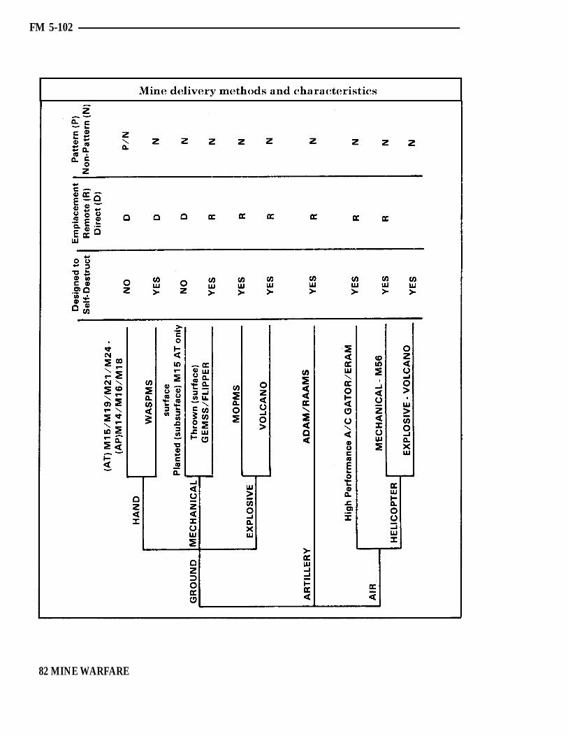
FM 5-102
82 MINE WARFARE

FM 5-102
MINE WARFARE 83
FM 5-102
MINEFIELD EMPLOYMENT
84
Mines are a significant combat weapon.Minefields are the most effective means ofreinforcing the terrain to stop, slow, orchannelize the enemy into areas where hecan be killed. Minefields can and should beemplaced wherever and whenever the tacticalsituation dictates. The commander’s flexi-bility in minefield employment has beenexpanded extensively with the fielding ofmultiple mine delivery systems. We can expectboth conventional and scatterable minefieldsto be the principal countermobility asset.Conventional and scatterable minefieldsshould be employed using the terrain analysisand obstacle planning sequence previouslyoutlined. Conventional and scatterableminefield locations should be preplannedprior to the beginning of the battle, andemplaced when the tactical situation requires.
Mine warfare operations must complementthe commander’s plan for defense, avoidimpeding friendly mobility, and facilitatefuture operations. The engineer is thecommander’s principal advisor in insuringthat these objectives are met. To achievesuccess in mine warfare, both the commanderand the engineer must carefully control mineemployment. Commanders and staffsthroughout the force must know and followauthorizations and requirements to emplacemines and report, record, mark, and co-ordinate minefields.
Detailed and integrated staff coordination isnecessary to develop plans for mine warfareoperations. Coordination begins with thedevelopment of a recommended obstacle planto support the commander’s scheme ofmaneuver and plan for fire support. Mine-field are incorporated into the obstacle planas necessary.
Preplanned conventional and scatterableminefields will be part of the obstacle plandeveloped for the commander by the engineer.The operations officer, fire support co-ordinator, aviation officer, and air liaison
MINE WARFARE
officer (ALO) will assist the engineer.Preplanning will consist of identifying areasfor minefields to respond to possible enemycourses of action. Preplanning will facilitaterapid emplacement, especially for minesdelivered by artillery, helicopter, and high-performance aircraft. In all cases, executionis a command decision of the responsiblemaneuver commander, who must select thedelivery system that best fits the tacticalsituation and presents the least risk tofriendly troops. Employment will be co-ordinated with higher, lower, and adjacentunits prior to execution, and reported andrecorded afterwards.
Conventional minefields will normally beemplaced prior to the beginning of hostilitiesdue to the exposure of manpower and equip-ment, and due to the length of time necessaryto emplace them. Once the battle begins,conventional minefields could still be em-placed but would have to be emplaced out ofdirect fire and, preferably, indirect fire range.Restriction to friendly maneuver or a rapidlychanging battlefield is another very im-portant factor to consider. Conventionalminefields would rarely, if ever, be emplacedforward of the forward line of own troops(FLOT).
Scatterable minefields can and should beplanned and emplaced throughout the battle-field as the tactical situation requires andassets allow. Some scatterable systems arebetter suited for specific areas of the battle-field than others. Ground scattering systemsare best utilized for emplacing larger tacticalminefields and rapid, small, point, or hastyminefields. These type minefields are usuallyemplaced in friendly controlled territory.Other scatterable systems such as Artillery,Gator, M56, and Volcano can be employedthroughout the battlefield. Emplacing heli-copter delivered mines in enemy territorydoes involve a great degree of risk to theaircraft and crew. Artillery and high-performance aircraft delivery systems can be
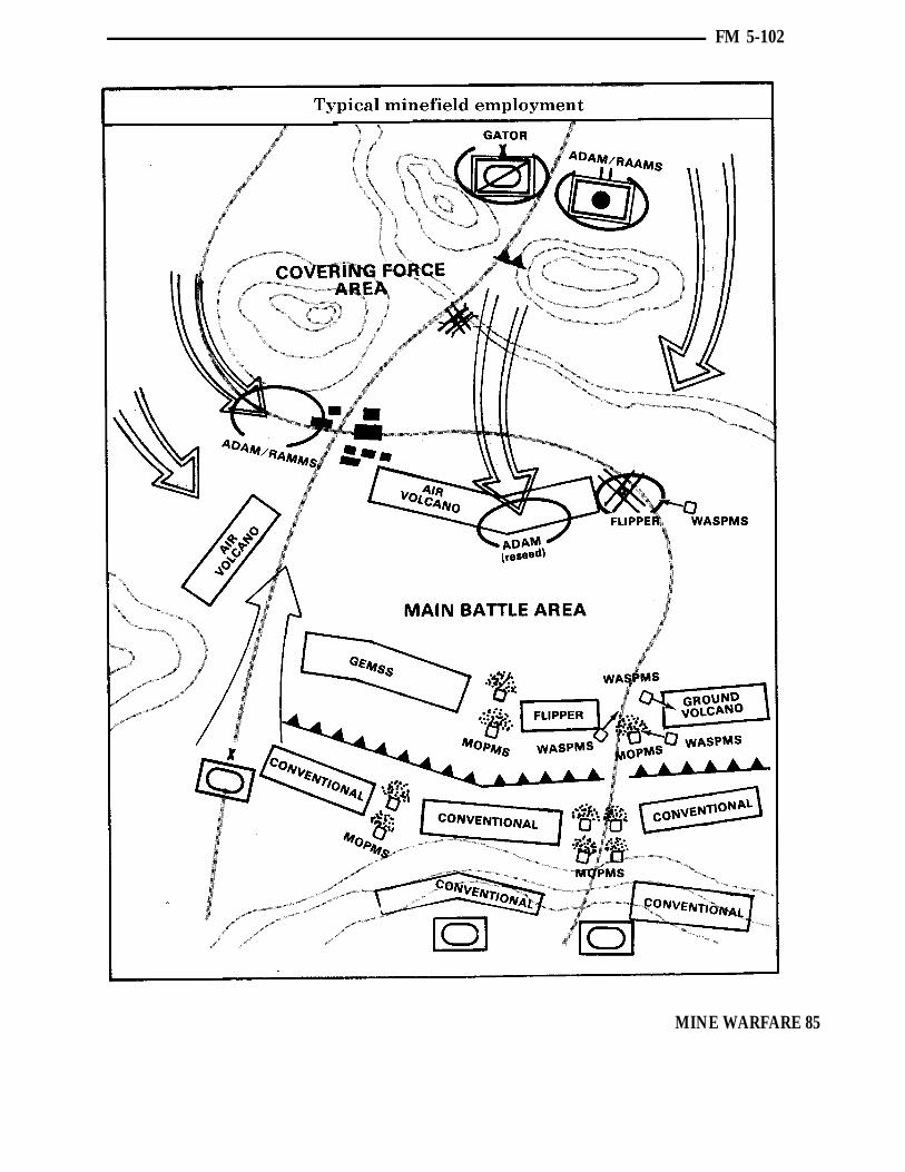
FM 5-102
MINE WARFARE 85

FM 5-102
employed anywhere, but are ideally suited to In recent wars, mines have accounted for adeliver mines into enemy controlled areas. substantial portion of equipment and per-
sonnel losses. Current and future develop-Employment of minefields must be carefully ments in mines and mine delivery systemsplanned and emplaced in areas where the are extensive, insuring that mines will be onecost to the enemy would be greatest. The of the most formidable assets on theengineer must recommend, and the tactical battlefield.commander must select, the type minefieldand delivery system to accomplish that task.
MINEFIELD EMPLOYMENT AUTHORITY
LEVELS OF AUTHORITYThe restrictions that minefields impose onfriendly mobility, as well as enemy mobility,dictate the need for positive and effectivecommand and control of mine employment.The echelon of command vested with theauthority to emplace mines varies with thepurpose of the minefield and type of mines(conventional or scatterable). Minefields thatrestrict maneuver to a greater degree requirea higher echelon of authority. In all cases, theresponsible commander must insure that theproposed field is coordinated with adjacent,higher, and subordinate units. The com-mander must further insure that limitationsto friendly maneuver are minimized, andthat all requirements for reporting, recording,and marking are met. Commanders maydelegate approval authority to lower echelonsas stated. Also, any higher echelon mayretain emplacement authority from sub-ordinate elements.
At the outset, the corps commander is theemployment authority for all scatterablemines. There are many possible combinationsof available options depending on the tacticalsituation and future plans. Some exampleoptions are:
The corps commander can delegateauthority for short self-destruct mines to
division commanders, and authorize themto delegate further. However, authority forlong self-destruct mines may be retainedat corps level.
The corps commander can delegateauthority to employ but designate mine-free areas or zones.
The general guidance to be followed is thelonger the self-destruct time of the mine, thehigher the employment authority should beretained. This criteria will prevent mineemployment from hampering future friendlyoffensive operations.
AREAS OFINFLUENCE AND INTEREST
The authority level is based upon the typeminefield, likely employment location, andimpact on friendly maneuver. The areas ofinfluence and interest for the tacticalcommander also provide a general referencefor employment authority for scatterablemines.
Area of influenceThe area of influence is an assigned area ofoperations wherein a commander is capableof acquiring and fighting enemy units withassets organic to or supporting the command.It is a geographical area, the size of which
86 MINE WARFARE

FM 5-102
MINE WARFARE 87

FM 5-102
DELIVERY RESOURCESdepends upon the factors of METT-T. It is Allocation of delivery resources provides anassigned by higher headquarters and des- additional control for the employmentignated by boundaries. authority. The means of delivery are related
to the authority to employ. Before delegatingArea of interest authority, the commanders must consider
The area of interest extends beyond the area their subordinate’s concept of operation.of influence. It includes territory which Delivery systems available should be pri-contains enemy forces capable of affecting oritized in allocation similar to other criticalfuture operations. The area of interest is resources.usually within the next higher headquarter’s,and a portion of adjacent unit’s, area ofinfluence.
88 MINE WARFARE

FM 5-102
REPORTING, RECORDING, AND MARKING
Once emplaced, minefields are lethal andunable to distinguish between friend andenemy. For this reason, positive control and acontinuous flow of information is necessary.Reporting, recording, and marking ofminefields must be performed using methodsthat are consistent and well understood. Thebasic differences between conventional andscatterable mines require that they be treateddifferently with respect to reporting, re-cording, and marking.
CONVENTIONALMINEFIELD REPORTING
A minefield report is an oral, electronic, orwritten communication concerning miningactivities, friendly or enemy. These reportsdocument information on friendly and enemyminefields. The information is transmittedthrough operation channels and furnished tointelligence staff officers. It is then processed,integrated with terrain intelligence, anddisseminated through intelligence channelsto affected units. Mandatory conventionalminefield reports are:
Report of Intention.
Report of Initiation.
Report of Completion.
These reports will be submitted by theemplacing unit commander through opera-tional channels to the operations officer(G-3/S-3) of the authorizing headquarters.That headquarters will integrate the reportswith terrain intelligence and disseminatethem through tactical intelligence. Thereports should be sent by secure means.
Report of IntentionThe Report of Intention is made as soon as itis decided to lay the minefield. It doubles as arequest when initiated at levels below thosewith authority to emplace. This report, when
required, includes the following required data(Standardization Agreement (STANAG)2036) on the proposed minefield:
Tactical purpose.
Type of minefield.
Estimated number and types of mines.
Whether mines are surface laid or buried.
Whether antihandling devices are used.
Location of minefield.
Location and width of lanes and gaps.
Proposed date and time for starting andcompleting.
Conventional minefields which are part of anoperation or general defense plan that hasbeen approved by the authorizing commanderdo not require a Report of Intention. Theirinclusion in such a plan implies an intentionto lay.
Report of InitiationThe Report of Initiation is a mandatoryreport made by the laying unit when in-stallation begins. It informs higher head-quarters that emplacement has begun andthe area is no longer safe for friendlymovement and maneuver.
Report of CompletionThe Report of Completion is usually an oralreport to the authorizing commander that theminefield is complete and functional. TheReport of Completion is followed as rapidlyas possible by the completed DA Form 1355(Minefield Record) or DA Form 1355-1-R(Hasty Protective Minefield Record). Com-pletion of the minefield records is theresponsibility of the laying unit.
MINE WARFARE 89

FM 5-102
Additional reportsAdditional reports may be required by theauthorizing commander.
Progress ReportDuring the emplacing process, the com-mander may require periodic reports on theamount of work completed.
Report of TransferThis is a written report which transfers theresponsibility for a minefield from onecommander to another. This report must besigned by both the relieved and relievingcommanders. It must include a certificatestating that the relieving commander hasbeen shown on the ground-or otherwiseinformed of—all mines within the zone ofresponsibility. It must state that the relievingcommander assumes full responsibility forthose mines. The Report of Transfer is sent tothe next higher commander who has au-thority over both relieved and relievingcommanders.
Report of ChangeThis report is made immediately to the nexthigher commander when the minefield isaltered. It is sent through channels to theheadquarters that keeps the written minerecord. A Report of Change is made as soonas changes in any of our minefields occur. Itis made by the commander responsible forsurveillance and maintenance of theminefield.
CONVENTIONALMINEFIELD RECORDING
All conventional minefields are recorded onDA Form 1355 (Minefield Record), except forhasty protective minefields, which are re-corded on DA Form 1355-1-R (HastyProtective Minefield Record).
ProceduresPreparing the standard minefield record formis the responsibility of the laying unit. Theofficer in charge of the laying must sign and
forward it to the next higher command assoon as possible. Once the information isentered, the form is classified SECRET orNATO SECRET, as required. The number ofcopies prepared depends on the type ofminefield and local procedures. Unit standingoperating procedures (SOPs) should providefor information on minefields being passed tohigher and lower command levels, andlaterally to adjacent units. When the record ismade, it should be reproduced at the lowestlevel having the necessary equipment to makecopies. Minefield records are circulated on a“need to know” basis. When used for training,they are marked SPECIMEN. Large mine-field are recorded on two or more DA Forms1355.
ChangesWhenever any changes are made to anexisting minefield, a completely new recordmust be prepared on DA Form 1355. Thisrecord is marked REVISED and shows theminefield as it is after the changes. Theoriginal minefield number remains un-changed. Some changes which require a newrecord are:
Relocation of mines in safe lanes.
Relocation of safe lanes.
Changed lane or minefield markings.
Inclusion of the minefield into a largerminefield system.
Removal or detonation of mines.
Addition of mines to the minefield.
Methods of recordingOverlayAn overlay should be used when the minefieldis to be related to operational maps. Standardmilitary symbols are used in preparing minewarfare overlays.
90 MINE WARFARE

Aerial photographsMinefields can be recorded by aerialphotographs if strip centerline tapes are keptin place until the camera work is done andprominent terrain points can be located.Aerial photographs can be used in conjunc-tion with DA Form 1355 and attached to thecompleted form.
Measuring azimuthAny type of angle-measuring device that canbe oriented in reference to magnetic Northcan be used to lay out or plot mines.
Conventional minefield records are forward-ed through operational channels to theaterArmy Headquarters where they will bemaintained on file by the theater engineer.Minefield records may be maintained on file
with the Assistant Corps Engineer in whose
FM 5-102
area of operation the minefield is located, ifdeemed necessary.
CONVENTIONALMINEFIELD MARKING
Minefields are marked as necessary to protectfriendly forces. Standardization Agreement(STANAG) 2889 is the authoritative referencefor marking conventional minefields emplacedby NATO forces. Normally, protective andtactical minefields will be fenced to protectfriendly troops, noncombatants, and domesticlivestock. In rear areas, minefields will befenced on all sides. Two-strand barbed wireor concertina fences with signs are minimumprotection. The Hand Emplaced MinefieldMarking Set (HEMMS) may also be used as a
MINE WARFARE 91

FM 5-102
marking means. Lanes will be marked usingstandard minefield marking sets. In forwardareas, minefields will normally be markedonly on the friendly (rear) side, or on thefriendly side and the flanks. Lanes will bemarked inconspicuously using wire, tape,rope, or easily identifiable terrain features.Minefield markings may be removed uponwithdrawal. Point and interdiction mine-field are not normally marked.
Shown on page 93 is a synopsis of con-ventional minefield reporting, recording, andmarking procedures.
SCATTERABLE MINEFIELDREPORTING AND RECORDING
Accurate, timely, and uniform reporting anddissemination of scatterable minefieldemplacement information is a must. Fluidand fast moving tactical situations require
that complete information on scatterablemine employment be known and passed on ina simple and rapid manner to all units thatcould be affected. The variety of emplacingsystems and emplacing units precludes theuse of locally devised reporting and dis-semination methods. Scatterable minefieldsmust also be recorded to facilitate clearingoperations after the war is over. They neednot be recorded in the detail required whenemplacing conventional mines. Since thelocations of individual scatterable mines areunknown, they cannot and need not be plottedas are conventional mines. The aim points orcorner points and the type mines emplaced isbasic information which must remain on filefor future reference and use.
Shown on pages 94-97 is a relatively simplereporting and recording procedure that willbe used for scatterable mines. It is applicablefor all delivery systems and can be sent in avoice, digital, or hard copy mode. This
92 MINE WARFARE

FM 5-102
procedure is based upon the various types ofemplacing systems. Some systems such asArtillery, Gator, and MOPMS are pointoriented with the safety zone calculated fromone or more aim points. Other systems suchas GEMSS and the M56 have distinct mine-field corner points which must be reported.The basic purpose of this procedure is toprovide one method that is uniform with allbasic information required to report andmaintain a record of scatterable mine em-ployment. This procedure also contains allthe information necessary to warn unitswhich may be affected. Warning informationcan easily be extracted and disseminated tounits which require it.
The unit emplacing the mines will im-mediately report the pertinent informationrequired by the most expeditious securemeans. If the initial report is not a hard copyreport, the emplacing unit will prepare thereport in hard copy as soon as possible. Thereport is sent through operations channels tothe headquarters authorizing the minefield.The information is posted on operations mapsand disseminated to units that are affected.The report is then forwarded in the samemanner as the conventional minefield recordto the senior engineer in the theater forpermanent retention. Forwarding the hardcopy report to the theater commander is nottime sensitive. Reports can be batched andforwarded when time permits.
160-337 0 - 94 - 4MINE WARFARE 93

FM 5-102
94 MINE WARFARE

FM 5-102
MINE WARFARE 95

FM 5-102
96 MINE WARFARE

FM 5-102
MINE WARFARE 97
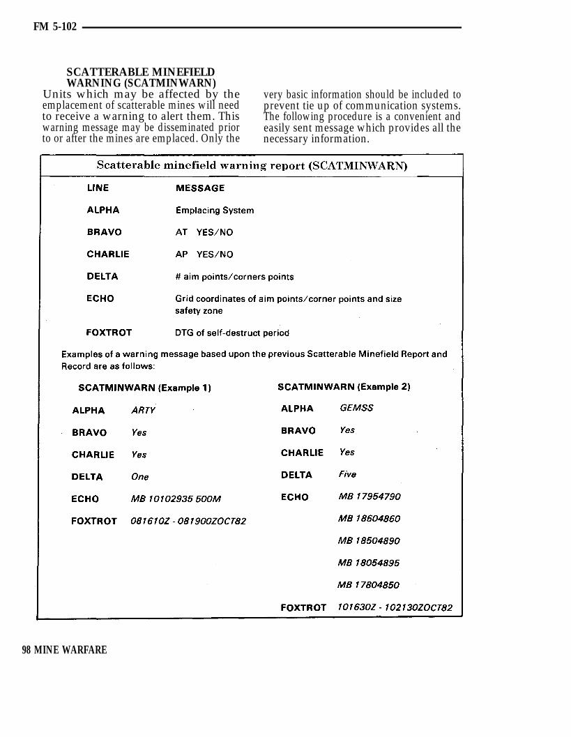
FM 5-102
SCATTERABLE MINEFIELDWARNING (SCATMINWARN)
Units which may be affected by the very basic information should be included toemplacement of scatterable mines will need prevent tie up of communication systems.to receive a warning to alert them. This The following procedure is a convenient andwarning message may be disseminated prior easily sent message which provides all theto or after the mines are emplaced. Only the necessary information.
98 MINE WARFARE
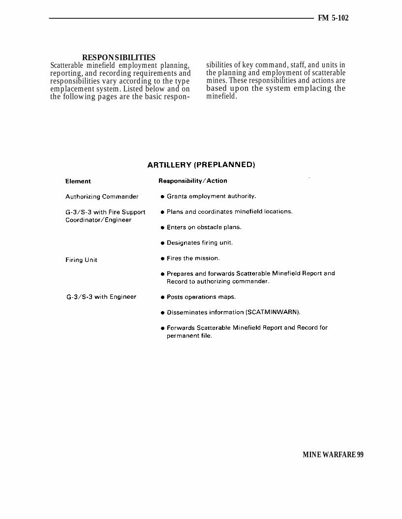
FM 5-102
RESPONSIBILITIESScatterable minefield employment planning, sibilities of key command, staff, and units inreporting, and recording requirements and the planning and employment of scatterableresponsibilities vary according to the type mines. These responsibilities and actions areemplacement system. Listed below and on based upon the system emplacing thethe following pages are the basic respon- minefield.
MINE WARFARE 99
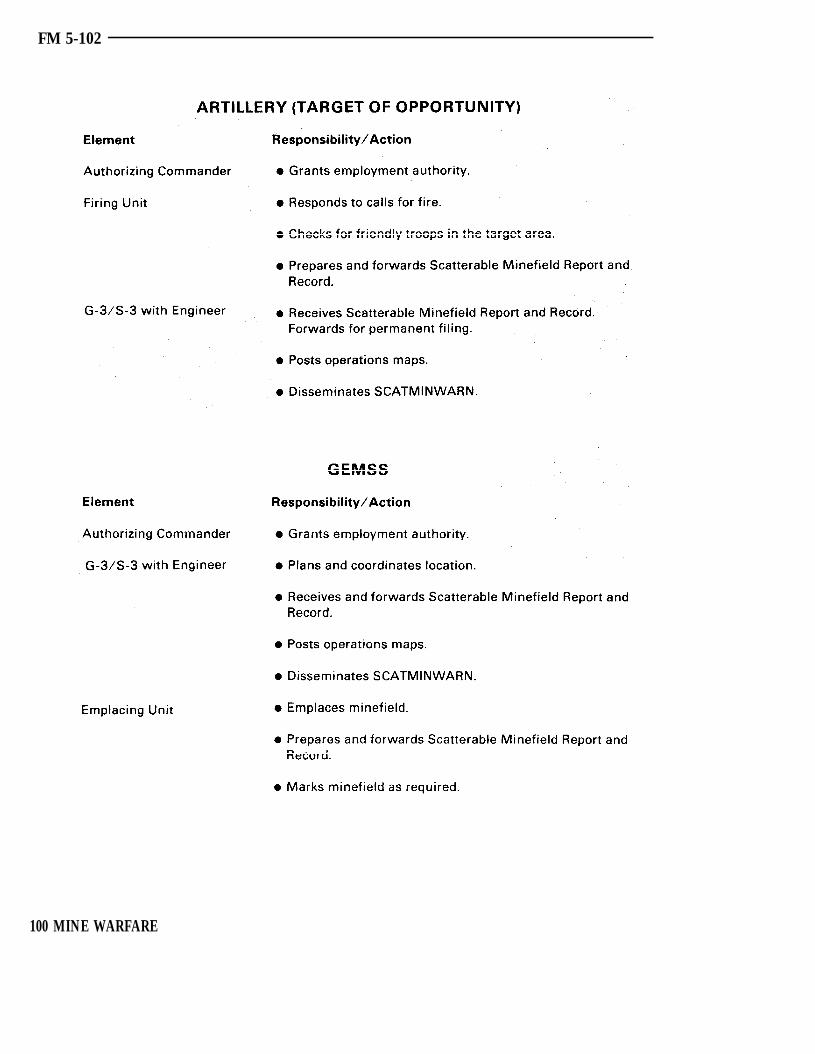
FM 5-102
100 MINE WARFARE

FM 5-102
MINE WARFARE 101
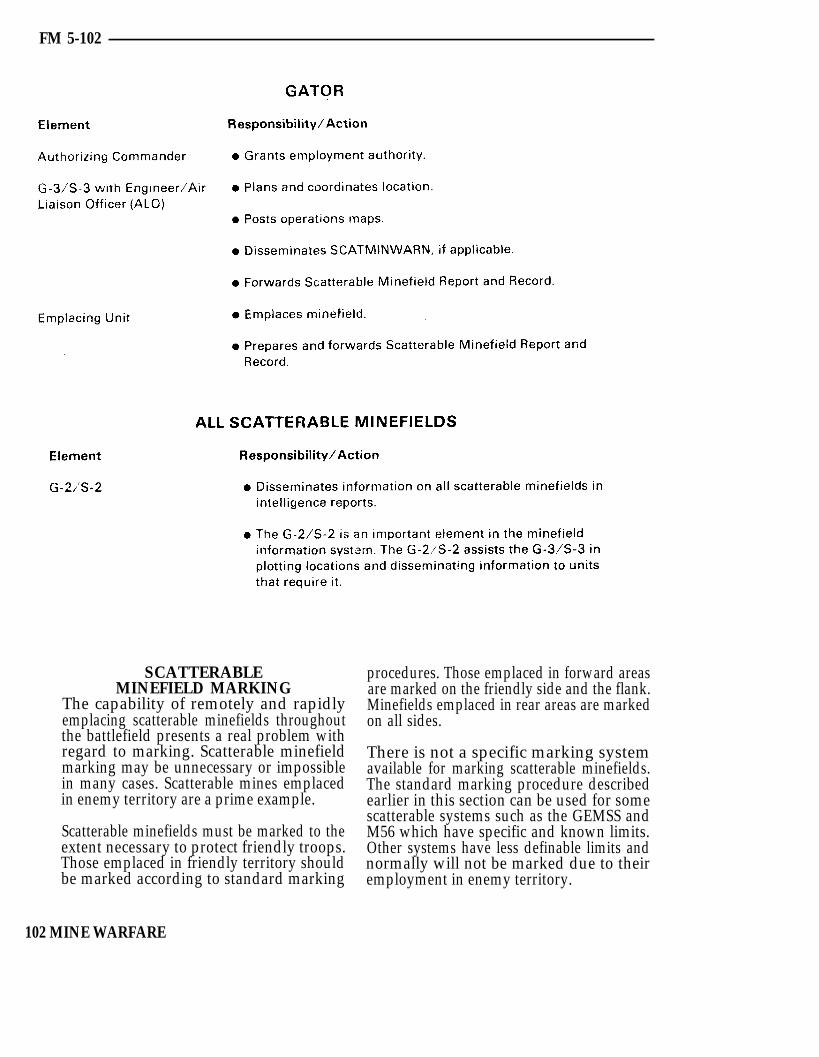
FM 5-102
SCATTERABLEMINEFIELD MARKING
The capability of remotely and rapidlyemplacing scatterable minefields throughoutthe battlefield presents a real problem withregard to marking. Scatterable minefieldmarking may be unnecessary or impossiblein many cases. Scatterable mines emplacedin enemy territory are a prime example.
Scatterable minefields must be marked to theextent necessary to protect friendly troops.Those emplaced in friendly territory shouldbe marked according to standard marking
procedures. Those emplaced in forward areasare marked on the friendly side and the flank.Minefields emplaced in rear areas are markedon all sides.
There is not a specific marking systemavailable for marking scatterable minefields.The standard marking procedure describedearlier in this section can be used for somescatterable systems such as the GEMSS andM56 which have specific and known limits.Other systems have less definable limits andnormally will not be marked due to theiremployment in enemy territory.
102 MINE WARFARE

FM 5-102
ENEMY MINEFIELD and must include all known informationREPORTING AND RECORDING about the minefield. The report is normally
Any detection, encounter, or knowledge of made through operations channels. Specificenemy minefields or mining activities must information and format of that informationbe reported by the fastest reliable means. The is outlined in STANAG 2096 and is as follows.report is made to the next higher commander,
MINE WARFARE 103

FM 5-102
SUMMARY
Conventional minefield key points
Minefields are classified as:
Protective.
Tactical.
Point.
Interdiction.
Phony.
There are three mandatory minefield reports:
Report of Intention to lay.
Report of Initiation of laying.
Report of Completion of laying.
There are two minefield record forms:
DA Form 1355 (Minefield Record).
DA Form 1355-1-R (Hasty ProtectiveMinefield Record).
Minefield sites are chosen with the primarypurpose of blocking, channeling, and killingthe enemy.
Lanes and gaps in minefields are used for thesafety of our own troops. Minefield plansmust be coordinated with adjacent units andplans for patrols, supporting fires, counter-attacks, withdrawals, and logistic support.
Scatterable minefield key points
Establish employment authority in theoperations order.
Plan potential scatterable mine locationsearly.
Emplace scatterable mines based upon enemydisposition and friendly mobility plan.
Report scatterable mine locations rapidly.
Disseminate information to affected units.
104 MINE WARFARE

Chapter 6OBSTACLES OTHER THAN MINEFIELDS
T here are many countermobility assets and methods at thecommander’s disposal. This chapter describes theemployment and execution of countermobility activities
other than minefields. Employing all types of obstacles will provideflexibility to the commander and increase the variety of obstaclesthat the enemy must encounter.
BRIDGE DEMOLITIONS
NON-NUCLEAR CRATERSANTITANK DITCHES
EXPEDIENT OBSTACLES
PRECONSTRUCTED OBSTACLES
ATOMIC DEMOLITION MUNITIONSSUMMARY
106
107
116
126
130
136
139
OBSTACLES OTHER THAN MINEFIELDS 105

FM 5-102
BRIDGE DEMOLITIONS
Streams and rivers are formidable obstaclesto mobility. In most developed countries ofthe world, bridges have been constructed tospan these waterways along lines of com-munication. Generally, roads and railroadsalso follow what would be likely militaryavenues of approach. The use of existingbridges is critical to the mobility of a militaryforce. Without existing bridges, forces mustconduct river crossings using tacticalbridging. A river crossing operation is one ofthe most difficult operations to performsuccessfully as it normally requires extensivetime and resources.
By demolishing or rendering existing bridgesunserviceable, we can force the enemy to usetime and resources to conduct tactical rivercrossings. The vulnerability of the enemy isgreatly increased during river crossings andpresents a good opportunity to destroy hisforces.
Bridge destruction cannot be accomplishedhaphazardly. There are several very im-portant factors that must be considered andplanned such as:
Extent of destruction.
When to demolish.
Coordination.
Resources.
Effects on local population.
EXTENT OF DESTRUCTIONOnly that portion of the bridge essential toaccomplish the military objective should bedestroyed. In some instances where the spanis short or the bridge has no intermediatesupports, destruction of the entire bridge maybe required. In other instances where the
bridge is large, dropping a single span mayprevent enemy use, conserve demolitions,and make the bridge easier to reconstruct at alater date. Enemy capability must be a primeconsideration in making this decision.
WHEN TO DEMOLISHThe answer to this question is tacticallydependent. Had the Germans blown theRemagen bridge several days earlier, manyof their problems would not have occurred.(See chapter 3.) At the same time, they mayhave isolated some of their forces on the farbank. If a bridge is blown too early, it maygive the enemy time to change direction andtherefore not impede his mobility at all.Waiting too long may enable the enemy tocapture the bridge intact. The commandermust make this tough decision only afterconsidering the factors involved.
COORDINATIONThe location of friendly forces and futureplans of the command are prime factors.Coordination is required with higher, lower,and adjacent units, as well as other servicesin many cases. A worst case example wouldbe for air assets to prematurely destroy abridge that would be a major avenue ofapproach for a ground counterattack.
RESOURCESMajor bridge destruction requires substantialamounts of time, personnel, and explosives.Planning and coordinating must occur earlyto insure that resources are available andtargets are executed at the proper time.
EFFECTS ON THELOCAL POPULATION
Unnecessary destruction of bridges has amajor impact upon the local population. Aswith any other denial target, care should betaken to minimize that impact.
106 OBSTACLES OTHER THAN MINEFIELDS
FM 5-102
NON-NUCLEAR CRATERS
Craters are effective obstacles to enemymovement when constructed properly andlocated at critical points along his movementroute. Craters are normally placed on roadsor other high speed movement routes theenemy is expected to use. They should beplaced at locations that cannot be easilybypassed such as cuts or fills. The basicpurposes are to delay or stop the enemy,cause his forces to bunch up and provide goodtargets, and force him to use up breachingassets such as bridging and earthmovingequipment. Use of antipersonnel and antitankmines in conjunction with craters createsformidable obstacles.
PLACINGCraters should be placed in depth to preventthe enemy from conducting a single breachand continuing on. There are essentially twoplacement methods:
1 Place craters adjacent to each other.
2 Place craters 100 to 1,000 meters apart.
Place craters adjacent to each other.This method makes the obstacle extremely
difficult to breach by earthmoving equipmentand by a tracked-vehicle launched bridge.The loose soil will cause the bridge to restunevenly, and exiting vehicles will have noplace to go except into an adjoining crater.When using this method, care must be takenduring the demolition process so that soilblown from one crater does not come to rest inadjacent craters and thus reduce theirobstacle value.
Place craters 100 to 1,000 metersapart. This method forces the enemy to
conduct several breaches. The factors ofMETT-T will determine the best crater design
and location. In any case, craters should betied into existing or reinforcing obstacles andcovered by direct fire weapons.
DESIGNINGTo be effective obstacles, craters must be toowide to be spanned by tracked vehicles, andtoo deep and steep-sided for any other vehicleto pass through them. Blasted road craterswill not stop modern tanks indefinitely,because repeated attempts by the tank totraverse the crater will pull loose soil from theslopes of the crater into the bottom, reducingboth crater depth and slope angles. Roadcraters must be large enough to tie intonatural or man-made obstacles at each end.The effectiveness of craters may be improvedby placing log hurdles on either side, diggingthe face nearly vertical on the friendly side,and mining the site with antitank andantipersonnel mines. Wire placed in the craterwill add to the difficulty of mine clearing.
BLOWINGThere are two common methods of blowingcraters:
1 Conventional method, using boreholesloaded with explosives.
2 The M180 Demolition Cratering Kit.
All military explosives may be used forblasting antitank craters. A special 40-poundcratering charge (ammonium nitrate) issuedin a waterproof metal container is specificallydesigned for blowing craters and, if available,should be used with the conventional method.The M180 kit comes complete with explosive.
1
2
OBSTACLES OTHER THAN MINEFIELDS 107
FM 5-102
CALCULATINGHasty road crater
A hasty road crater is emplaced when time feet wide with side slopes of 25 to 35 degrees.and explosives are limited. It is not as ef- In forming a hasty road crater, all boreholesfective as the deliberate crater, which will be must beat least 5 feet deep, each loaded withdescribed later. The hasty cratering method at least 50 pounds of explosive. Following areproduces a crater 6 to 7 feet deep, and 20 to 25 the steps necessary to blow a hasty crater.
Step 1: Calculate the number of boreholes necessary. Use the formula:
N = Number of boreholes
L = Length of crater desired measured across the width of the roadway from the outsideof where you want the crater to extend to. Do not measure just the roadway if youwant the crater to extend wider than the roadway itself.
Example
Step 2: Space the boreholes 5 feet apart starting at the center of the roadway and extending ineach direction of the desired crater.
Step 3: Dig all boreholes to the same depth (at least 5 feet).Step 4: Load each borehole with 50 pounds of explosive.
Step 5: Dual prime all charges with detonating cord and connect them to fire simultaneously.
Step 6: Stem or backfill all boreholes with suitable material (soil or sandbags).Step 7: Blow the crater.
Deliberate road crater deliberate crater are the same as a hastyThis cratering method produces road craters crater with the following exceptions:which are more effective than those resultingfrom the hasty method but require more time End holes are 7 feet deep and contain 80and explosive. The deliberate method pro- pounds of explosive.duces a deeper (7 to 8 feet), wider (25 feet), andsteeper-sided (30 to 37 degrees) crater than Each alternate hole is 5 feet deep andthe hasty method. The calculations for a contains 40 pounds of explosive.
Do not place 5-foot holes next to each other.
108 OBSTACLES OTHER THAN MINEFIELDS
FM 5-102
OBSTACLES OTHER THAN MINEFIELDS 109
FM 5-102
Relieved face road craterThis cratering method produces road cratersthat are more effective obstacles to moderntanks than the hasty or deliberate method,but they require still more time and explosivethan the hasty or deliberate. This techniqueproduces a trapezoidal-shaped crater about 7feet deep and 25 to 30 feet wide with unequalside slopes. In compact soil such as clay, therelieved face cratering method will provide
an obstacle shaped as shown in the top view,page 111. The side nearest the enemy slopesat about 25 degrees from the road surface tothe bottom, while that on the opposite orfriendly side is about 30 to 40 degrees steep.The exact shape, however, depends on thetype of soil found in the area of operations.The procedure is as follows:
Step 1: On dirt or gravel-surfaced roads, drill or blast two rows of boreholes 8 feet apart,spacing the boreholes on 7-foot centers. On hard-surfaced roads, drill the two rows 12feet apart. The number of charges for the friendly side row can be calculated by theformula:
L = length of crater in feet measured across the width of the road.
Any fractional number of holes should be rounded UP to the next highest number.Stagger the boreholes in the row on the enemy side in relationship to the other row, asshown in the sideview, on page 111. The enemy side row will always contain one lessborehole than the row on the friendly side.
Step 2: Make the boreholes on the friendly side 5 feet deep and load with 40 pounds of explosive;on the enemy side, 4 feet deep and load with 30 pounds of explosive.
Step 3: Prime the charges in each row separately for simultaneous detonation. There should bea detonation delay of ½ to 1½ seconds between rows, the row on the enemy side beingdetonated first. Best results will be obtained if the charges on the friendly side are firedwhile the earth moved in the first row is still in the air. Standard delay caps may be usedfor delay detonation.
Step 4: If adequate means for sufficient time for delay firing are not available, acceptableresults may be obtained by firing both rows simultaneously. However, the resultingcrater will not have the same depth and trapezoidal shape as previously described.
Step 5: To prevent misfires from the shock and blast of the row of charges on the enemy side(detonated first), the detonating cord mains and branch lines of the row on the friendlyside (detonated last) must be protected by a covering of about 6 inches of earth.
Angled road craterThis method is useful against tanks traveling boreholes are drilled across the roadway atin defiles or road cuts where they must about a 45-degree angle as shown. Because ofapproach the crater straightway. The road the angle tanks must attempt to cross, theycrater is blasted using either the hasty or tend to slip sideways and ride off their tracks.deliberate cratering methods, except the
110 OBSTACLES OTHER THAN MINEFIELDS
FM 5-102
OBSTACLES OTHER THAN MINEFIELDS 111
FM 5-102
MAKING BOREHOLESBoreholes for cratering charges may be dugby using motorized post hole augers or hand-held post hole augers or diggers, or blastedusing shaped charges. Making the boreholesis normally the most time-consuming taskrelated to cratering.
Breaching hard-surfaced pavementsHard-surfaced pavement of roads andairfields is breached so that holes may be dugfor cratering charges. This is done effectivelyby exploding tamped charges on the pave-ment surface. A 1-pound charge of explosiveis used for each 2 inches of pavementthickness. The charge is tamped with materialtwice as thick as the pavement. Boreholeswhich have been drilled or blasted throughpavement and contain placed charges canalso breach pavement. (A shaped chargereadily blasts a small diameter boreholethrough the pavement and into the subgrade.)Concrete should not be breached at anexpansion joint because the concrete willshatter irregularly.
Blasting with shaped chargesStandard shaped charges may be used toblast boreholes in both paved and unpavedsurfaces for rapid road cratering with ex-plosives. The 15-pound M2A4 shaped charge,detonated at 3½ foot-standoff, and the 40-pound M3A1 shaped charge, detonated at 5-foot standoff; will blast boreholes of depthsup to 9 feet with diameters 7 inches and largerin both reinforced concrete pavements andgravel-surfaced roads. For maximum ef-fectiveness, M3A1 shaped charges should beused to blast boreholes in thick, reinforcedconcrete pavements laid on dense high-strength base courses. The M2A4 shapedcharges may be used effectively to blastcratering charge boreholes in reinforcedconcrete pavement of less than 6-inch thick-ness laid on thin base courses, or to blastboreholes in unpaved roads. Almost all typesof military explosive, including the crateringcharges, can be loaded directly into boreholes
made by the M3A1 and M2A4 shaped charges.Shaped charges do not always produce openboreholes capable of being loaded directlywith 7-inch diameter cratering chargeswithout removing some earth or wideningnarrow areas. Many boreholes having narrowdiameters but great depth can be widenedsimply by knocking material from the con-stricted areas with a pole or rod, or bybreaking off the shattered surface concretewith a pick or crowbar. For road cratering onasphalt or concrete-surfaced roadways,blasting the boreholes with shaped chargeswill expedite the cratering task by elimi-nating the requirement for first breachingthe pavement with explosive charges.
Blasting in permafrostA good rule of thumb is to increase by one-and-one-half to two times the number ofboreholes and charges from those calculatedby standard formulas for moderate climates.Frozen soil, when blasted, breaks into largeclods 12 to 18 inches thick and 6 to 8 feet indiameter. As the charge has insufficient forceto blow these clods clear of the hole, they willfall back into it when the blast subsides.Testing should be made to determine thenumber of boreholes needed before extensiveblasting is attempted. In some cases, per-mafrost may be as difficult to blast as solidrock.
Using standard drill equipment has oneserious defect—the air holes in the drill bitsfreeze and there is no known method ofavoidance. Steam point drilling is satis-factory in sand, silt or clay, but not in gravel.Charges must be placed immediately uponwithdrawal of the steam point, otherwise thearea around the hole thaws and plugs it.Shaped charges also are satisfactory forproducing boreholes, especially for cratering.A low velocity explosive like ammoniumnitrate should be used if available. Theheaving quality of low velocity explosiveswill aid in clearing the hole of large boulders.
112 OBSTACLES OTHER THAN MINEFIELDS

FM 5-102
Blasting iceAccess holes
If only high velocity explosives are available, Access holes are used for water supply andcharges should be tamped with water and to determine ice thickness in computing safepermitted to freeze. Unless high velocity bearing pressures for aircraft and ve-explosives are thoroughly tamped, they tend hicles. As ice carries much winter traffic, itsto blow out of the borehole. bearing capacity must be rapidly ascertained
OBSTACLES OTHER THAN MINEFIELDS 113

FM 5-102
when forward movements are required. Smalldiameter access holes are made by shapedcharges. On solid lake ice, the M2A4penetrates 7 feet and the M3A1, 12 feet. Thesecharges will penetrate farther, but thepenetration distances were only tested in iceapproximately 12 feet thick. If the regularstandoff is used, a large crater forms at thetop which makes considerable probingnecessary to find the borehole. If a standoff of42 inches or more is used with M2A4 shapedcharge, a clean hole without a top crater isformed. Holes made by the M2A4 average 3½inches in diameter, while those made by theM3A1 average 6 inches.
Ice conditionsIn the late winter, ice grows weaker andchanges color from blue to white due to aging.Although ice structure varies and its strengthdepends on age, air temperature, andconditions of the original formation, the samesize and type of crater is formed regardless ofthe standoff distance. If the lake or river isnot frozen to the bottom and there is a foot ormore water under the ice, the water will rise towithin 6 inches of the top after the hole isblown, carrying shattered ice particles withit. This makes the hole easy to clean. If thelake is frozen to the bottom, the blown holewill fill with shattered ice and clearing will beextremely difficult. Under some conditions,shaped charges may penetrate to a depthmuch less than that indicated in the table onpage 113.
Surface chargesSurface craters may be made with ammoniumnitrate cratering charges or demolitionblocks. For the best effects, the charges areplaced on the surface of cleared ice andtamped on top with snow. The tendency of iceto shatter more readily than soil should beconsidered when charges are computed.
Underwater chargesCharges are placed underwater by firstmaking boreholes in the ice with shapedcharges, and then placing the charge belowthe ice. An 80-pound charge of M3 demolitionblocks under ice 472 feet thick forms a crater40 feet in diameter. This crater, however, isfilled with floating ice particles and, attemperatures around 20 degrees Fahrenheit(F), freezes over in 40 minutes.
A vehicle obstacle may be cratered in ice bysinking boreholes 9 feet apart in staggeredrows. Charges (tetrytol or plastic) are sus-pended about 2 feet below the bottom of theice by means of cord with sticks bridging thetops of the holes. The size of the chargedepends upon the thickness of the ice. Anobstacle like this may retard or halt enemyvehicles for approximately 24 hours at tem-peratures around -24 degrees F.
THE M180DEMOLITION CRATERING KIT
The M180 demolition cratering kit is speciallydesigned to produce craters in all types of soiland road surfaces, to include reinforcedconcrete. The kit is self-contained and con-sists of a shaped charge, a firing device, a40-pound cratering charge, rocket motor,tripod, and demolition circuit. The M180 cancreate craters much more rapidly thanmethods previously described. The M180 canbe employed in various configurationsdependent upon the width of the desiredcrater. The figure on page 115 shows how todetermine the number of kits necessary tocrater roads of varying widths, and properspacing and alignment. The M180 can beerected and fired within 20 minutes of arrivalon site by two soldiers. It requires no sitepreparation.
114 OBSTACLES OTHER THAN MINEFIELDS

FM 5-102
OBSTACLES OTHER THAN MINEFIELDS 115
FM 5-102
ANTITANK DITCHES
Tank ditches are one way to degrade an confusing the crews. Well-planned tankattacking force’s speed and mobility. They ditches have the advantages shown andimpede the advance by slowing vehicles and described.
116 OBSTACLES OTHER THAN MINEFIELDS

FM 5-102
OBSTACLES OTHER THAN MINEFIELDS 117

FM 5-102
EMPLOYMENTTank ditches should complement existingobstacles to include:
Slopes greater than 35 degrees.
Steps over 1.5 meters high.
Ravines, gullies, and ditches wider than 3meters.
Swamps and marshes over 1 meter deep.
Forests having trees over 8 inches indiameter.
Forests having 15 degree slopes and treesover 4 inches in diameter.
Built-up areas.
Construction of antitank ditches is time andequipment intensive. Maximum use shouldbe made of the terrain. Also, the shortestantitank ditch or ditch system possible shouldbe used.
A tank ditch alone is not an adequate obstacleand will not stop a determined attacker.Additional procedures to increase ditcheffectiveness are to—
Locate the tank ditch within the maximumeffective range of antitank weapons fromcovered and concealed firing positions.
Preplan artillery and air strikes in antitankditch areas. Artillery and air strikes forcethe enemy to button up while attempting tobreach the ditch, making him more vul-nerable to direct fire weapons.
Emplace antitank mines on both friendlyand enemy sides of the ditch, especially inthe loose soil material and the ditch bottom,to multiply effectiveness. Even the smallestditch wilI strip mine plows and rollers fromthe front of the attacking force, thusmaking the enemy more vulnerable to
mines on the friendly side of the tankditch.
Place concertina wire, water, or anti-personnel mines in the ditch to keepdismounted troops from working in theditch and creating gaps by hand. The wireand water also improve the ditch’s ef-fectiveness against attacking tanks.
Tie ends of tank ditches into existingobstacles such as steep slopes, woodedareas, and man-made structures. Rampsused in entering the ditch should be cut offand denied enemy access after completionof the ditch. This can be done withadditional “dressing-up,” using equipmentor mine and wire obstacles. Mines shouldbe used at the ends of the ditch to precludebeing easily bypassed.
When planning emplacement of tank ditches,keep this in mind: Soviet commandersrely on carefully rehearsed tactical for-mations for control in the attack. Youcan disrupt the momentum of the attack andforce directional changes in attackingvehicles, thus exposing their vulnerableflanks. This is done by imaginative place-ment of ditches with other obstacles. Tankditches should be placed in a series or, if timeis available, in a random pattern. Placing theditch or ditches at 90-degree angles to enemy’savenue of approach may not always be thebest tactical use. Consider the terrain andassets available, and construct ditches in apattern that will confuse, present good tar-gets, and force the enemy to use resources tobreach.
DESIGNThe configuration of the most effective tankditch has been a subject of much discussionand field testing with such constraints astime and equipment available, and soilconditions. The most efficient ditch is either arectangular or triangular ditch.
118 OBSTACLES OTHER THAN MINEFIELDS

FM 5-102
OBSTACLES OTHER THAN MINEFIELDS 119

FM 5-102
Frequently, you can save time, materials,and manpower by improving existing gulliesor ditches rather than constructing entirelynew ones. One method is to excavate alongnatural drainage or contour lines to create asidehill cut ditch. It would be beneficial ifthe ditch can be made to retain water. Muddysoil further degrades mobility. Place antitankmines in the soil and antipersonnel mines in
the bottom of the ditch to discourage infantrysoldiers. Depending on soil type, sides ofditches may have to be reinforced to preventcrumbling, and also to make the ditch moredifficult to cross. Continuous direct fireshould cover the ditch and force the enemy todeploy before reaching the ditch. Scatterablemines on probable approach routes canfurther slow vehicular movement.
120 OBSTACLES OTHER THAN MINEFIELDS
FM 5-102
Rectangular ditchesConstructionA ditch 3.3 meters wide cannot be “bridged”by tanks alone.
A ditch 1.5 meters deep in consolidated, firmsoil cannot be crossed by tanks or othervehicles without the aid of bridging orearthmoving equipment.
A ditch 1.2 meters deep in firm soil should beconsidered “expedient” and capable of onlya few minutes delay on the attacker.
Rectangular ditches in sand must be greaterthan 1.6 meters deep to be considered morethan just an expedient ditch.
Rectangular ditches should have a 1- to2-meter berm on their friendly side whichserves to increase the obstacle height,
impede breaching with scissor-type bridges,and keep the enemy from pushing the soilback into the ditch without exposing theirdozers or tanks with plows.
Effects and resultsThe effectiveness of tank ditches is measuredby the delay time imposed and targetspresented. It is a function of soil type andcondition, and ditch width and depth. Therectangular ditch has proven to be the mosteffective in imposing delays in both direc-tions. Results of tests on crossing rectangularditches in various soil types are shownbelow. The ditch must be wide enough toprevent the tank from simply running over it,and narrow enough to force the tank toexpose itself to our defense firepower. A3.3-meter width (equivalent to a D7 dozer’s
decrease traction to crossing tanks, greatly blade) satisfies this criteria.
OBSTACLES OTHER THAN MINEFIELDS 121

FM 5-102
Triangular ditchesConstructionEntrance slope is not critical in determiningthe effectiveness of triangular ditches.
Subjective estimates suggest “the steeper thewall the better.”
A ditch 1.5 meters deep in hard clayey soilscannot be breached by tanks alone exceptunder unusual conditions.
A ditch 1.2 meters deep in hard soil should beconsidered “expedient” and capable ofimposing only a few minutes delay on theattacker.
Triangular ditches in sand must be greaterthan 1.8 meters deep to be considered morethan just an expedient ditch.
To deny the use of the triangular tank ditchas a fighting position for the attacking armor,
the spoil should be spread loosely on theenemy side rather than used as a berm. Thiswill also reduce tank traction whenapproaching the ditch.
Effects and resultsResults of tests on crossing triangular ditchesin various soil types and resulting delaytimes are shown below. Triangular ditchesare two to four times faster to cross thanrectangular ditches when counterattacking.All tanks can easily cross from the friendlyside, and most smaller combat vehicles cancounterattack across if following in laneswhere tanks have crossed.
EQUIPMENTEarthmoving equipment such as the M9Armored Combat Earthmover (ACE), dozers,scrapers, Combat Engineer Vehicles (CEVs),and bucket loaders can all be used for tank
122 OBSTACLES OTHER THAN MINEFIELDS

ditching. Generally, the equipment is muchmore effective if used in teams rather thanalone. The M9s, dozers, and scrapers aremost effective, while bucket loaders andCEVs are used as a last resort. Variouscombinations can be used. Some typical teamconfigurations could be:
Two M9s or dozers.
One M9 and two scoop loaders.
Two or more tractor/scrapers used intandem.
One M9, dozer, and tractor/scraper used intandem. (Generally, one M9 or dozer fortwo scrapers works best.)
Scrapers only; some may have to bebobtailed to use as pushers.
FM 5-102
This list is not inclusive. Units should practiceand experiment using various equipment andoperator combinations to determine whatworks best for their area and what equipmentis available. Frozen or extremely hard soilwill most likely have to be ripped with doze~mounted rippers prior to digging.
METHODSFollowing are four proven methods for tankditch construction using organic engineerequipment.
Two dozers or two M9s (ACES) as ateam. In step 1, vehicle #1 will start theditch and push a load up to 9 to 10 meters (29to 33 feet) from the start point, and then backup to start the cut again. In step 2, vehicle #2will push the load away from the ditch toform a berm as vehicle #1 is backing up. Theteam continues performing in this manner to
OBSTACLES OTHER THAN MINEFIELDS 123

FM 5-102
construct the ditch. This “T-push” method issuitable for construction of tank ditches in allsoil types.
One dozer and one scoop loader, grader,or CEV as a team. This step is performedthe same as the previous method except thatthe loader or CEV is used in place of vehicle#2. The grader is available to keep the bermstraight and built up. After the ditch isconstructed, and if time permits, the bermcan then be further shaped. Normally, thismethod would be less productive than thefirst method. Again, more than one team maybe used to construct the ditch.
Tractor/scrapers in tandem as a team.Using tractor/scraper in tandem as a team isan excellent method of tank ditch construc-tion. The scrapers can have the pan attachedor use the tractor in a bobtailed configurationas a pusher to assist in loading. Each loadedscraper travels the full length of the tankditch and exits toward the friendly side of theditch to spread the load and form the berm. A
grader can also be used to shape and smooththe berm which will reduce scraper-operatorfatigue. “Bean bag” lights can assist duringnight operation to guide operators andparticularly to mark the turn out point. Thismethod utilizes only horizontal constructionassets, and may free other diggers such asM9s, dozers, and bucket loaders to performother missions.
Tractor/scraper and M9s or dozers intandem as a team. This method uses scrapersas earthmovers and generally requires apusher (such as an M9, dozer, or bobtailedscraper) to assist loading of the scrapers. Asthe pusher and scraper exit the ditch, thescraper will turn toward the friendly side todump the load along the berm; the pusher willexit on the enemy side and proceed back tothe beginning of the ditch to pick up anotherscraper. This method produces excellentresults, but requires training to reduce idleequipment time spent waiting for a pusher orscraper.
124 OBSTACLES OTHER THAN MINEFIELDS

FM 5-102
Operator training is an absolute must toattain maximum production. Experimentingwith various equipment combinations andsoil conditions is valuable to determine thebest production for a specific area ofoperations and given equipment availability.
Production timeBasic production data of estimated con-struction times is shown for a 1.5 meter by 3.3meter ditch using the teams indicated. Theseproduction rates are based upon field tests.No significant differences exist betweenconstruction of a triangular or a rectangularditch. Valid test data does not exist forequipment combinations other than thoselisted.
Construction at nightTank ditching can be accomplished underblackout conditions. However, production willnot be as great, and certain precautions needto be taken. Equipment operators need anobject such as a “bean bag” light or flashlightwith red lens to focus upon to assist indigging a straight ditch. Also, night visiondevices, if available, are excellent foroperators to use. Scraper operators particu-larly need to have a guide or light to leadthem out of the ditch and prevent turning outearly and overturning. Night operations willbe a must in order to emplace the number oftank ditches that will probably be necessary.Commanders should recognize this fact andtrain under conditions of darkness.
Construction by demolitionThe utilization and effectiveness of explosivesfor tank ditching are still being studied.Considerable effort has been devoted to thesubject. The concept of using liquid bulkexplosive and buried pipes is currently beingtested and evaluated. This concept hassignificant advantages; for example, the pipesare buried during peacetime and, when atank ditch is required, the pipes are filledwith explosive and detonated.
OBSTACLES OTHER THAN MINEFIELDS 125
FM 5-102
The cratering methods described earlier canalso be used to explosively create tank ditches.Some clearing and shaping of the ditch willnormally be required to increase its ef-fectiveness.
Construction usingequipment and explosives
When encountering hard soils or rocky groundto be excavated, rippers used to loosen andbreak the soil aid in excavation and are themost economical. Should the rippers be unableto loosen the material for excavation, “pre-blasting,” or the use of demolitions could beemployed using shaped, cratering, line, orburied tamped explosive charges to breakupthe ground. This technique will shatter thematerial sufficiently to make excavationeasier and thereby raising production rates.An advantage to be considered is that
preblasting allows less powerful pieces ofequipment, like the tractor/scraper, to digditches out of previously hard material.
Should the tactical situation dictate thatdozers be used for other tasks, preblastingmay make it possible to excavate with scoop-loaders. With dozers, preblasting may sub-stantially increase production rates anddecrease “downtime.” Preblasting will surelydecrease wear and tear on machines andoperators.
For the combat engineer who has limitedtypes and numbers of equipment, limitedcapability, and large numbers of tasks,equipment utilization in conjunction withpreblasting may turn an impossible tankditch mission into merely a difficult one.
EXPEDIENT OBSTACLESExpedient obstacles are basically created byusing what nature has placed in the area.Imagination and ingenuity are the key factorsin successfully constructing and employingexpedient obstacles. The possibilities forexpedient obstacle creation are almostendless. A few of the more obvious are:
Abatis.
Log obstacles (including hurdles, cribs,and posts).
Rubble.
Junked automobiles and battle-damagedequipment.
Flooding.
Fires.
ABATISAn abatis is an effective obstacle againsttanks and other vehicles in a heavily-woodedarea with few roads or trails. An abatis canbe constructed rapidly using demolition tofell trees. The trees should be felled at a 45-degree angle to the road or trail. The treeshould remain attached to the stump to makethe obstacle more effective and difficult toclear.
To calculate the amount of explosive nec-essary for tree cutting, use the formula:D (diameter of the tree trunk, in inches)squared divided by 50, for a test shot.
This formula is used to compute the amountof TNT required. The results of the test shotwill determine if more or less explosive isnecessary for subsequent shots.
Place the charges at a height of 5 feet abovethe ground. The trees will fall toward the sidewhere the explosive is placed. One side of the
126 OBSTACLES OTHER THAN MINEFIELDS

FM 5-102
abatis should be blown, and the other sidedelayed, until the first row has fallen.
If time allows, mines, wire, and booby trapscan be added to make clearing more difficult.Modular Pack Mine System (MOPMS) ex-ploded on the obstacle adds an excellent tank“killer” capability.
LOG OBSTACLESThere are many different types of log ob-stacles that can be constructed using localmaterials. Log obstacles are most effectivewhen the lack of a bypass forces the enemy tobreach them. Although they are time andlabor intensive, and locations for theiremployment are limited, they do not requiremuch logistic support. Log obstacles can be
constructed entirely by hand. The availabilityof chain saws and bucket loaders or backhoeswill significantly reduce construction time.Log obstacles can and should be used inconjunction with other obstacles to increasetheir stopping power.
Log hurdlesLog hurdles can be constructed using logsgreater than 10 inches in diameter. The sizeof the logs will dictate if the hurdles should beconstructed of single logs or multiple logs tiedtogether. On level ground, log hurdles willnot stop tanks, but will cause them to slowdown. Hurdles will improve the effectivenessof other obstacles by slowing enemy vehiclesand making them more vulnerable to friendlyweapon fire.
OBSTACLES OTHER THAN MINEFIELDS 127

FM 5-102
Log cribsLog hurdles can stop tanks on uphill grades.The significant factor is determining howhigh to construct the hurdle. A field expedientmethod to determine the height of the hurdleis to use a stick about 12 feet long, stick theuphill end in the ground, and depress thestick until it is level. The distance betweenthe downhill end of the stick and the groundis how high to construct the hurdle. Thehurdle should be sited on the steepest part ofthe slope and as near the top as possible.
Rectangular or triangular log cribs areused effectively as roadblocks where standingtimber is available, and where such anobstacle cannot be readily bypassed. Unlesssubstantially built, obstacles of this type arenot effective against heavy-tracked vehicles.Cribs are strengthened by filling them withearth. It is preferable to obtain the earth bydigging a shallow ditch in front of theobstacle. Log hurdles in front of a log crib willforce vehicles to reduce speed and add to theeffectiveness of the roadblock.
128 OBSTACLES OTHER THAN MINEFIELDS

FM 5-102
Log postsPosts are among the best antivehicularobstacles because each post presentsbreaching problems to the attacker. Thereare no fast methods of breaching a belt ofposts. Normally, the attacker will try tobypass such an obstacle. Therefore, postobstacles should be placed where bypassrequires much time and effort. Posts shouldbe hardwood with a minimum diameter of 40
All posts are buried 1.5 meters (5 feet) in theground, either vertically or at a slight angletoward the enemy, and project between 75 to120 centimeters (30 to 48 inches) above groundlevel. The height should vary from post topost. The minimum acceptable density forposts is 200 per 100 meters (328 feet) of front.The spacing should be irregular, with at least1 meter (3.3 feet), and not more than 2 meters
centimeters (15.8 inches). (6.6 feet), between posts.
OBSTACLES OTHER THAN MINEFIELDS 129

FM 5-102
The effect of post type obstacles can beimproved, and the obstacles made moredifficult to breach, by weaving spirals ofbarbed wire among the posts. ExplodingMOPMS into the obstacle after completiongreatly increases its effectiveness. Con-ventional mines can also be used to make theobstacle more difficult to breach.
RUBBLERubble created as a result of combat in townsand villages can be used as obstacles incertain situations. Buildings can be inten-tionally rubbled by the 165 millimeter (mm)demolition gun on the CEV or by use ofexplosives. Mines added to the rubble willgreatly prolong the clearing process.
JUNKED AUTOMOBILES ANDBATTLE-DAMAGED EQUIPMENT
When used to create road blocks, these itemsshould be securely anchored to the ground if
material and time permit. Using mines withthe obstacle increases its effectiveness.
FLOODINGControlled flooding can be an effectiveexpedient obstacle. Demolishing dams, canalwalls, or levees can cause flooding to impedeenemy movement.
FIRESControlled burning of wooded areas, woodenbridges, and other areas is another expedientobstacle method to prevent enemy use. Bothflooding and burning generally fall into thearea of denial operations and will be closelycontrolled.
Expedient methods of obstacle creation arelimited only by imagination and ingenuity.The ability to find something that workswhen there appears to be nothing available isa long-standing trait of the American soldier.
PRECONSTRUCTED OBSTACLESPreconstructed obstacles are obstacles thatare prepared in peacetime for rapid executiononce hostilities begin. They are generallydesigned and constructed not to be obtrusiveor interfere with vehicular traffic untilexecuted. Preconstructed obstacles aregenerally of the following types:
Shafts sunk into the roadway at criticalareas such as cuts, fills, and defiles, whichwill later be loaded with demolition tocreate road craters.
Shafts that are constructed for installationof a steel beam instead of demolition.
Bridges constructed with hollow demo-lition chambers in the piers and abutments.
Tunnels with planned cavities fordemolition placement.
Massive concrete blocks suspended aboveor beside the roadway at selected locationswhich can be dropped into the roadwaywhen needed.
Preconstructed obstacles reduce the militaryeffort for obstacle emplacement. They alsogreatly expedite the emplacement processonce the appropriate alert or readiness postureis given.
PRECONSTRUCTED OBSTACLESIN NORTH ATLANTIC
TREATY ORGANIZATION (NATO)Once a location for a preconstructed obstacleis selected, a request is forwarded throughmilitary channels to the host nation defenseministry. The location is based upon goodmilitary obstacle location techniques. Thehost nation will then evaluate the requestand be responsible for the construction of the
130 OBSTACLES OTHER THAN MINEFIELDS
FM 5-102
obstacle and the demolition storage site if oneis required.
A target folder with all pertinent informationwill be prepared by the military regioncommand in whose area the obstacle islocated. A copy of the demolition target folderwill be provided to the engineer unit re-sponsible for execution of the obstacle.
Wallmeister teams, a unit of the host nationTerritorial Army, assist and support theengineer commander in all aspects of engineertechnical subjects in the assigned area. TheWallmeister will perform maintenance and
security checks of the preconstructed obstaclefixtures at regular intervals.
PRECHAMBER SHAFT SYSTEMThe prechamber shaft system consists of anarray of several individual demolition shaftsdesigned to permit rapid execution of craterobstacles. The demolition shafts are con-structed of concrete pipe and located on roads,railroads, and bridge abutments.
The individual demolition shafts that com-prise the system are 4 to 6 meters (13 to 20feet) deep and 60 centimeters (24 inches) indiameter. The shafts are installed either
OBSTACLES OTHER THAN MINEFIELDS 131
FM 5-102
vertically or at an angle, and each shaft isclosed by a steel shaft cover which resemblesa sewer manhole cover. Two detonation cordconduits are installed in a straight line fromthe interior of the demolition shafts to ametal cover box installed in the embankmentor curbstones of the road. These conduits areprovided to accommodate the main andreserve firings systems.
The demolition material required for aprechamber shaft system is stored in a nearby5-ton bunker complex and is earmarked forthe sole use at its designated obstacle site.The prestocked demolition material consistsof:
The required number of DM41s, a 25-kilogram demolition block, cylindrical inshape similar to a large block of cheese(four cheese charges per 1-meter (3.3-foot)depth).
The appropriate number of nonelectricblasting caps and capwell adapters.
Sufficient detonation cord for both theprimary and reserve ring mains and branchlines.
In addition to the demolition materials,several special tools are necessary to installthe target. One T-handle wrench, two shaftcover lifting hooks, and two loading poles areusually organic to most European-basedcombat engineer squads. In some instances,these tools may be stored at the obstacle site.The T-handle wrench and shaft cover liftinghooks are stored in one cover box, whereasthe loading poles are stored in one of thedemolition shafts.
The opening and loading of prechambersshould begin at the prechamber shaft locatednearest the enemy and progress towards thefriendly side. This is also the order in whichdemolitions should be off-loaded at each shaft.To open the shaft, use the T-handle wrench to
remove the safety cap and loosen and unscrewthe hexagonal nut. Insert the cover liftinghooks in the shaft cover; lift the cover off theshaft and place it to the side of the pre-chamber. Lift the traverse (located beneaththe cover) by rotating it in a circular motionuntil it hits a stop which will allow one end totilt toward the top of the prechamber and beremoved.
To load a prechamber shaft with 25-kilogramcheese charges, the loading pole sections arescrewed together and hooked into the carryinghandles of the demolition charge. The chargesare lowered into the shaft and stacked on topof the others. The last charge in each shaft islowered only after it has been dual primednonelectrically with branch lines.
The firing systems are installed by pullingthe branch lines through the conduits whichrun beneath the road surface from the shaftto the cover box. Once the end of the branchline has been pulled through the conductusing the plastic lines provided in the conduit,the crossbar is replaced, and the shaft coversecured in place. Both primary and reservering mains are laid to the side of the roadwayfor attachment of the branch lines.
The standard planning factor for completeinstallation of a three-shaft system dictatesthat a nine-member squad requires 90 minutesto complete the task.
BEAM POST OBSTACLEThe beam post obstacle is designed forblocking roads at defiles without destroyingthe pavement. The obstacle consists of steelI-beam posts inserted into preconstructedshafts in the road width which preventsmovement of all vehicles, wheeled or armored.A minimum of two double rows of shaftsmust be preconstructed into a concretefoundation. Within each double row, theindividual shafts must also be staggered.Each beam post shaft is 80 centimeters (31inches) deep and has a steel cover. The I-
132 OBSTACLES OTHER THAN MINEFIELDS
FM 5-102
beam post is constructed of sectional steel, 2.2meters (7.2 feet) long and weighing 216kilograms. When inserted into the shaft itwill extend 1.4 meters above the road surface.Each steel I-beam post is equipped withlocking devices which prohibit the enemyfrom pulling them out of the shafts.
The beam post obstacle is emplaced byremoving the shaft covers after unscrewingthe hexagonal nuts with T-handle wrenches.Lifting hooks, organic to an engineer squad,are used to place the shaft covers to the side.As with the prechamber shaft system, removal of the crossbar allows access to theshaft. Carrying bars are employed to bringthe I-beam posts to each shaft. Each beam is adesignated four-soldier carry for lowering the
posts into the shafts. Once emplaced, theenemy side double row may be improvedthrough the addition of concertina wire andcamouflage netting.
The standard planning factor for completeinstallation of a beam post obstacle 12 meters(39 feet) in width, three double rows deep(requiring a total of 54 I-beam posts), dictatesthat two squads, each with nine members,require 2 hours to complete the task.
DEMOLITION FIXTURESIN BRIDGES
Demolition fixtures in bridges permit thedestruction of such targets by expediting theinstallation procedures and simultaneouslyallowing friendly use of the bridge. There is a
OBSTACLES OTHER THAN MINEFIELDS 133
FM 5-102
demolition target folder prepared for eachbridge equipped with a demolition fixture.Primarily, three types of bridge fixtures existthroughout the European Theater:
1 Charge mounting brackets.
2 Demolition chambers.
3 Demolition galleries.
1 Charge mounting brackets are sheetmetal rails permanently mounted to the
base of the supporting columns of a bridge.They are used to facilitate the placement ofcutting charges and to insure their secureattachment. The 9-kilogram, DM19 cuttingcharge is equipped with lockable standoffsliding slats which are “L” shaped at thebottom for installation into the chargemounting brackets.
2 Demolition chambers are cavities builtin the intermediate support columns and
abutments of bridges. These types of fixturesare secured by means of a locked metal accesspanel. Demolition chambers are designed toaccommodate large quantities of conven-tional munitions, cratering charges, andsatchel charges.
3 Demolition galleries are constructedin very large bridges. The galleries lead
under the abutments of bridges or under theroadway and terminate in a demolitionchamber or cavity. Because of the largequantities of explosives necessary to destroysuch large targets, the galleries are con-structed to allow the uninhibited movementof personnel carrying munitions to thechambers. The primary demolition materialused to execute this type of target is the 25-kilogram, DM41, cheese charge. Bridge fix-tures of this nature have permanentlyinstalled electric firing circuits through aseries of conduits usually from one chamberto the next. Both the main and reserve firingsystems end in a distribution box located atthe abutments.
Before preparing abridge for deliberate demo-litions in accordance with the demolitiontarget folder, prepare the target for hastydemolition, if feasible. Because no demolitionmaterial is earmarked for hasty demolition, itmust be taken from the combat load of the per-tinent unit. As the demolition target is beingprepared for deliberate firing, the charges forhasty demolitions will be removed.
Planning data on required labor, material,and time for loading and preparing the targetfor firing can be found in the respectivedemolition target folder.
PRECONSTRUCTED OBSTACLESIN KOREA
The terrain in Korea is rugged with narrowarmor approaches between mountains. Theneed for rapidly emplaced antiarmor ob-stacles, coupled with restricted terrain, makespreconstructed obstacles an excellent choice.
Varying types of preconstructed, obstaclesare found in Korea, the majority being thefalling block type. These are large concreteblocks suspended above or beside the road-way. Demolitions are stored nearby to blowthe concrete block supports when the ap-propriate alert measure has been receivedand the tactical situation permits. Pre-constructed obstacles are the responsibilityof the Korean Government to construct, andthe Republic of Korea (ROK) Army tomaintain and execute.
ADDITIONAL OBSTACLESOther types of in-place obstacles are tankwalls, mined areas, and obstacles at selectedriver crossing sites. Preconstructed obstaclesare key to the defense in that they are properlylocated and can be executed quickly withminimal manpower. Tactical considerationsand advantages of preconstructed obstaclesare numerous. For example, they—
Are quickly executed.
Allow the use of the area prior to hostilities.
134 OBSTACLES OTHER THAN MINEFIELDS
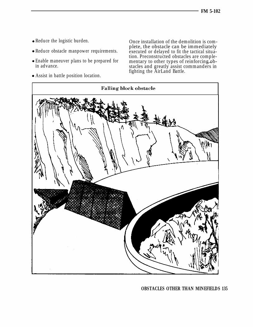
FM 5-102
Reduce the logistic burden. Once installation of the demolition is com-plete, the obstacle can be immediately
Reduce obstacle manpower requirements. executed or delayed to fit the tactical situa-tion. Preconstructed obstacles are comple-
Enable maneuver plans to be prepared for mentary to other types of reinforcing ob-—in advance. stacles and greatly assist commanders in
fighting the AirLand Battle.Assist in battle position location.
OBSTACLES OTHER THAN MINEFIELDS 135

ATOMIC DEMOLITION MUNITIONS
FM 5-102
Atomic Demolition Munitions (ADM) arenuclear demolition devices used primarily forobstacle creation or denial operations. ADMcan only be used when the authority toemploy nuclear weapons has been granted.In the AirLand Battle, commanders shouldplan for, request release of, and use nuclearweapons at the time when they will have thegreatest effect on the enemy. Special charac-teristics make ADM most desirable on thebattlefield. These characteristics are dis-cussed in the following paragraphs. TheSpecial Atomic Demolition Munition (SADM)is the ADM system currently in use. TheSADM can be carried by personnel, and is alow yield weapon fired by a timer mechanism.
CAPABILITIES OF ADMAtomic Demolition Munitions have a muchhigher destructive power than conventionalexplosives. In order to achieve similar effects,a massive amount of conventional explosivewould have to be used. The logistic andmanpower requirements are greatly reducedwhen ADM are used rather than conventionalexplosive. There is no delivery error withADM. This is a significant advantage overany other type delivery system when absoluteaccuracy is required such as a bridge ortunnel. Fallout, induced radiation, andcollateral damage can be controlled orminimized by using ADM. A much largeryield weapos would have to be used tocompensate for delivery error.
For example, consider the destruction ofmajor highway bridges. A subkiloton SADMdetonated subsurface in the center of thehighway would create the desired obstacle.Considering delivery error associated withartillery-, aircraft-, and missile-deliveredsystems, and the inability to detonate these
delivered systems at the surface or sub-surface, yields in the 50-kiloton range wouldbe required to assure creation of the desiredobstacle with any other nuclear system. Theadvantages resulting from using the loweryield ADM in tactical operations are sig-nificant.
ADM TARGETSTunnels
Most tunnels cannot be severely damaged ordestroyed with conventional explosivesbecause of the vast quantity required and thedifficulty to concentrate the explosive powerof such a large volume at a single point. AnADM placed inside most tunnels will severelydamage them and create an obstacle thatcould take several weeks to breach.
Major highwaysIn order to effectively crater a major highwaywith conventional explosives, a large amountof haul capacity, personnel, demolitions,and—most important—time would be re-quired.
A low yield SADM detonated subsurface oron the surface would produce an obstacle thatthe enemy could not breach with assaultbridging. Breaching would require extensivefoundation preparation and installation of afixed bridge. Even when not under fire, suchconstruction could require days to complete.
BridgesPreparing a major highway bridge couldrequire an engineer battalion’s entire haulcapability and several company hours whenusing conventional explosive demolitions.The same bridge could be destroyed in a fewminutes by an ADM firing team with a lowyield SADM.
136 OBSTACLES OTHER THAN MINEFIELDS
FM 5-102
Other potential ADM targets include massivedams, canals, airfields, railroad switch yards,ports, industrial plants, power facilities,supply depots, and narrow valley defiles.
ADM EMPLOYMENTThe primary purpose of ADM is to createobstacles. The purpose of any obstacle orsystem of obstacles is to control enemymovement. This control means to stop hismovement, slow his rate of advance, orchange the direction of his movement. Oncethe enemy has been stopped, he must decidewhether to breach or bypass the obstacle. Heloses time during this decision process andpresents a good target to friendly weapons. Ifhe decides to breach the obstacle, he losesmore time because his rate of advance will beslowed. Forces awaiting the completion ofthe breaching operation will present vul-nerable targets. If he decides to bypass theobstacle, he loses time because of the lessdirect route to his objective. When ADM orany other obstacles are emplaced, friendlyforces should consider the bypass routesavailable and also create obstacles there orplan direct or indirect fire.
In both offensive and defensive roles, theADM acts as a combat multiplier. ADM usedto reinforce terrain will create very significantobstacles in terms of cratering and treeblowdown. When covered by direct or indirectfire and reinforced with scatterable mines,the enemy must expend considerable re-sources to overcome the obstacle and willmost likely choose to bypass it. The residualradioactive contamination adds to the ob-stacle’s effectiveness. The overall effect is tocause local concentration of enemy forces,thus creating better targets for conventionaland nuclear weapon systems.
OBSTACLES OTHER THAN MINEFIELDS 137

FM 5-102
ADM in the offenseOne of the roles that ADM can play in theattack is to provide protection to the flanks ofthe attacking formation, particularly in crosscompartmented terrain. The ADM can beused to seal likely enemy counterattackavenues of approach. Another role for ADMin the offense is to create obstacles behind theenemy to prevent escape from the attackingforces. Yet another is a close interdiction roleto separate enemy first and second echelonforces by destruction of key highway and railbridges in enemy territory. The ADM can
(SOF) augmentation will most likely berequired for ADM placed behind enemy lines.
ADM in the defenseThe greatest utility of ADM is in defensiveoperations. The effective creation of criticalobstacles can enable a relatively small forceto hold off a large attacking force untilreinforcements arrive. In the defense, ADMis used to create key obstacles, block dan-gerous avenues of approach, and deny theenemy use of important installations and—
also be used in rear areas to disrupt main facilities.supply routes. Special Operations Forces
138 OBSTACLES OTHER THAN MINEFIELDS

FM 5-102
SUMMARYObstacles other than minefields span thespectrum from a simple log hurdle to a verycomplicated and precise bridge demolition.Methods, materials, and equipment span thesame spectrum. Several simple rules shouldbe followed when selecting and emplacingobstacles other than minefields:
Know threat capabilities and make sure thatthe obstacle or obstacles selected will accom-plish the mission.
Know the capabilities of your soldiers andtheir equipment.
Plan early; time is generally the most criticalresource in obstacle construction.
Tie the obstacle in with existing or otherreinforcing obstacles.
Cover the obstacle by fire if at all possible.
Know the future mobility plan of friendlyforces.
Forecast logistic and haul requirements early.
Train with combined arms team at everyopportunity.
OBSTACLES OTHER THAN MINEFIELDS 139

Chapter 7DENIAL OPERATIONS
Throughout history, denial operations have been an intergalpart of military operations. This chapter describes theauthority and responsibilities for denial operations, and
identifies denial targets and methods in the overall planningprocess.
AUTHORITY AND RESPONSIBILITY
DENIAL TARGETS
DENIAL METHODS
DENIAL PLANNING
SUMMARY
141
142
145
147
149
140 DENIAL OPERATIONS

AUTHORITY AND RESPONSIBILITY
FM 5-102
A denial measure is an action to deny theenemy the use of space, personnel, or facil-ities. It may include destruction, removal,contamination, or obstacle construction.Denial operations have always been animportant facet that, in many cases,determined the outcome of wars. Denialoperations over the years have ranged fromthe siege of forts or castles to the destructionof ball bearing plants.
There is a reasonably fine line that dis-tinguishes denial operations from obstacleemplacement. Obstacles are normally em-placed to assist in destroying the enemy inthe immediate vicinity of the obstacle. Denialoperations normally are not focused uponimmediate enemy destruction, but are de-signed to accomplish a more strategic pur-pose. If planned and conducted properly,denial operations contribute to future opera-tions and have a far reaching impact on thebattlefield. By their strategic nature, theyalso may have a much greater impact uponthe civilian population. Flooding a valley orstrategically bombing an industrial complexare examples of denial operations that impactimmediately upon civilian population with adelayed effect upon military operations.
AUTHORITYDenial targets have as their object theprevention of the enemy’s beneficial use ofsome area, facility, or resource. The targetsfrequently involve civil objects, and ajudgment must be carefully made regardingthe balance of military importance and thecivil impact of destruction or evacuation.Evacuation or destruction must be made infull accord with the Law of War. Accordingly,execution authority for denial targets mustbe centralized.
The theater commander, subject to nationalpolicies and limitations, is authorized toconduct denial operations as a part of theoverall campaign. The theater commander
establishes the policies governing denialoperations in the theater, and delegatesplanning and execution to service componentcommanders and subordinate joint forcecommanders. In developing denial policies,the theater commander will consider nationaland multinational policies and limitations,and possible reciprocal action by the enemy.Extensive consideration must be given tothose facilities and areas required to supportcivilization in the post-hostility periodregardless of the outcome of the conflict. Thelong-range social, economic, political, andpsychological effects of excessive destructionof civil properties and material must beweighed against the military advantagesgained.
RESPONSIBILITYCorps commanders are responsible for trans-lating the theater commander’s policy intooperational plans and missions. Corpsplanners must perform a detailed analysis ofthe areas of operation. Specific targets areselected and assigned to subordinates forexecution. Prohibited targets must also beidentified. Corps commanders will specifyconditions for execution. Any discretionaryareas for subordinate commanders must alsobe specified, as well as any conditions orplanning guidance.
Division commanders are responsible forexecuting denial operations within their area.In accordance with the denial policy of thetheater and mission assignments of the corps,the division plan provides for the denial ofboth military and civilian supplies, equip-ment, and installations with clearly identifiedmilitary value. Division denial operationsare generally a major task, requiring a highdegree of technical skill and considerabletime for detailed planning, careful prepa-ration, and execution.
Brigade, battalion, and other commandersplan and execute denial targets as they are
DENIAL OPERATIONS 141

FM 5-102
assigned missions in combat plans andorders. Denial operations are the respon-sibility of all elements of the combined armsteam. Although combat engineers are par-ticularly suited for executing denial operationswith heavy equipment and demolitions,troops of other arms and services can alsohelp extensively. Transportation and otherlogistic units can conduct denial by evac-
uation of strategic equipment and materials.Air Force aircraft can also contribute.
To be successful, denial operations must becomprehensive. Thus, in warfare conductedin a modern state, denial operations willprobably exceed the capability for engineerexecution alone. All available effort shouldbe used.
DENIAL TARGETS
The most frequently selected denial targetsand methods of destruction are discussed inthis section. Some of the reinforcing obstaclesthat have been discussed in previous chaptersmay also be used in denial operations.
DENIAL OF AREASAreas can be denied to the enemy; however,the length of the denial period may varywidely depending upon the type of denialmethod used and enemy capability and desire.Areas can be denied by:
Demolitions that deny access to the area.
Chemical or radiological contamination.
Floods.
Delayed-action explosives.
Construction of obstacles.
Isolation through interdiction or de-struction.
Weapons fire.
Maneuver.
DENIAL OF INSTALLATIONSOR FACILITIES
For both strategic and tactical reasons, denialof key installations and facilities is desirableinmost situations. Selected denial targets areintegrated into the overall strategic andtactical concepts of the theater.
RailwaysEffective denial of the railway system dis-rupts one of the enemy’s principal transpor-tation means. It necessitates a systematicdenial of major structures, facilities, loco-motives, and rolling stock essential to thesystem’s operation. To deny a rail net, it isnecessary to cut all rail lines runninggenerally parallel to the axis of enemyadvance. The number of complete cuts re-quired depends on the length of delay desired.The best specific targets are major bridges,tunnels, and defiles. The most importantsupporting targets are railway terminalfacilities such as roundhouses, shops, andmarshaling yards, locomotives, and rollingstock. When friendly forces desire to reusefacilities with a limited rebuilding effort, therailway system may be effectively denied tothe enemy by removing or destroying special-type rail sections such as frogs, switches, orguardrails.
142 DENIAL OPERATIONS

FM 5-102
HighwaysIf the railway system is successfully denied,the enemy must depend on other trans-portation. Highway system denial com-plements railway system denial and is ofconsiderable significance. It should be noted,however, that restoration of the highwaysystem by replacement or repair of bridgesand other structures is generally easier andfaster than restoration of the railway system.Denial of the highway system, therefore, isnot effective for as long a time as denial of therailway system. Specific targets best suitedfor denial of a highway system are majorbridges, tunnels, and defiles.
AirwaysThe airway system is highly important to theenemy for tactical and strategic operations,as well as for limited combat service support.Other than aircraft (which are evacuated ordestroyed), the specific targets are theairfields. Airfields can be denied by crateringthe runways and destroying key supportingfacilities. Atomic Demolition Munitions(ADM) are particularly suitable for thismission.
Petroleum, oils, and lubricantsPetroleum, oils, and lubricants (POL) systemdenial includes, in addition to the destructionof bulk POL, the destruction of terminalstorage, producing, refining, and dispensingfacilities, as well as facilities for transportingbulk POL. The amount of destruction requiredvaries, depending on the particular areaunder consideration, since destruction of asingle key facility may eliminate the need forother destruction. For example, in an arealacking in oil production but having re-fineries, the enemy would be unable to use therefineries if all bulk POL handling andstorage facilities were destroyed.
Electric powerDenial of major electric power systemsimpairs the operation of heavy industries.Denial should provide for the systematicdestruction of key generating plants. Sincetransformer stations form the heart of trans-mission systems, they are usually the mostsuitable denial targets for disrupting powerservice with the least effort. The destructionof electric power systems has a considerableimpact on the local civilian population, andthis factor must also be considered.
CommunicationsDisruption of major communications systemsshould provide for the destruction of tele-phone and telegraph exchanges, repeaterstations, and radio stations only. Morecomplete denial has a greater effect on thecivilian population than on the enemy mili-tary effort.
Inland waterwaysIn well-developed areas, particularly inWestern Europe, inland waterways are highlydeveloped and carry a large part of totalfreight traffic. The waterways system can bedenied by destroying the dams, siphons,aqueducts, embankment or levee walls, locksand gates, barges, and other floating craft, aswell as by obstructing the waterways.Drawdown of reservoirs can deny the enemywaterway use, and it can also be a means offlooding.
UtilitiesThe destruction of water, gas, and sewagesystems ordinarily has little or no militaryeffect on the enemy, but has a most harmfuleffect on the local population. Unless amarked military advantage accrues, such asin the denial of water to the enemy in a desertor riverine area, utility systems should not beimpaired.
DENIAL OPERATIONS 143
FM 5-102
PortsPorts can be destroyed by nuclear or con-ventional demolitions; scuttling ships inharbors, across bars, alongside quays, piers,and docks; removing or destroying cranes,lighters, tugs, rail facilities, channel markers,and communications equipment; removingpilots and key navigational personnel; anddestroying bulk POL-handling equipment.
Potable waterThe denial of potable water is feasible inareas of the world where water is scarce.Storage containers and water sources such aswells or pipelines can be destroyed or thewater made unfit to drink. The possible ad-verse effect on the command and the localpopulation, however, must also be taken intoaccount. Consideration should also be givento patrolling lines of communication toprevent water resupply from sources outsidethe immediate area.
DENIAL OF MATERIALThe destruction of material is a commanddecision and, except in extreme cases, is doneonly on authority of a division or higher unitcommander. The general policy is maximumevacuation and minimum destruction. Localcivilian material of strategic or tactical valueshould be denied the enemy, particularly if he
144 DENIAL OPERATIONS
is critically short of some items and requiresthe local items for further operations. Thefollowing items are among those whichnormally are denied to the enemy:
Nuclear energy facilities and relatedequipment.
Bulk POL stocks.
Locomotives and rolling stock.
Critical industrial components such asindustrial diamonds, electronic equipment,ball and roller bearings, and aircraftengines.
Highway transport equipment.
Floating equipment and all harborfacilities such as hoists, cranes, locks, andship repair facilities.
SELECTION OF DENIAL TARGETSA denial operation carried to an extremewould remove or destroy everything thatcould aid the enemy in any way. Becausemilitary assets are always limited, however,denial operations must be planned andcoordinated carefully to insure the militaryvalue of the target, and to determine thepriority of destruction. Coordination withcivil affairs personnel is particular im-portant. Effective denial operations will betargeted against objectives with high militaryvalue and full consideration will be given tothe needs for particular facilities in the posthostility period. Whenever possible, denialtargets should be selected to aggravate enemystrategic weaknesses and limitations. Inselecting denial targets, commanders shouldinsure that they meet one of the followingcriteria. If this denial target is executed, lossof this capability to the enemy should:
Disrupt logistical support capabilities.
Prevent the use of local materials, supplies,and equipment to reinforce or augmentoffensive capabilities.
Require the diversion of significantengineer and operational efforts for repair,reconstruction, or rehabilitation to supportmilitary operations.
Delay the movement and distribution ofreplacements, supplies, equipment, andreserve units by forcing them to usesecondary and low speed routes of advanceand movement.
Restrict tactical or strategic mobility.
Denial targets must meet the test of one of theabove criteria. They must meet those criteriain a substantial—not incidental—manner.

FM 5-102
Furthermore, the means selected to deny theintended object should be one reasonablyavailable and capable of producing the leastdamage to civil property.
For example, while it may not be appropriateto rubble a large portion of a town totemporarily close a major route, it could bejustified to destroy a major bridge to close
that same roadway. However, such deter-minations must be made at appropriate levelsof command based on the circumstances atthe time. Using the same example, if a rapidlyadvancing enemy force can be stopped mosteffectively by blocking a major route withrubble from destroyed buildings, such actionwould not be prohibited by the Law of War.
DENIAL METHODS
REMOVALEvacuation of material is as much a part ofdenial operations as destruction and shouldalways be considered first. Evacuation mustbe started early and conducted in accordancewith prepared priority lists. Selective removalcan be quite useful; however, the capability ofthe enemy to replace missing components orcomplete items must be accurately assessed.Selective removal is most profitable when theitem removed is already critical to the enemy.All like items (or selected components),including spares, must be removed. Tech-nicians may be required for meticulousselective removal.
DESTRUCTIONExplosives are generally used for destruction;however, other means can also be used.
FireDestruction by burning is a valuable tech-nique; however, some materials that areconsidered to be capable of burning will notburn. The advice of engineers should besecured before planning destruction byburning. The security of the tactical operationmust also be considered; intentions towithdraw may be given away by the burning.
MachineryRotating or reciprocating machinery usuallyrequires lubrication to prevent damage fromfriction. Such machinery can be damaged or
destroyed by removing or contaminating thelubricants. The operator of the machinery ora technician is the best source of advice onrapid destruction methods of machineryitems.
WaterWater can damage many items beyond repair.The effectiveness of water as a destructivemeans should be checked with a specialist onthe item or material. Destruction by watercan usually be done quietly and withoutdisclosing future plans or intentions.
MechanicalMechanical methods (such as breaking witha sledgehammer) can also cause destruction.An informed operator can achieve maximumdamage with a minimum of effort.
CuttingDestruction by cutting vital metallic membersof a structure with welding torches is simple,easily learned, and a positive technique, butthe equipment required is heavy.
GrenadesThermate grenades are useful in denyingcertain targets; the intense heat producedfuses the metallic portions of the target ordistorts them beyond usefulness. The use ofthermate grenades must be planned inadvance so that they, and the experts whouse them, are available.
DENIAL OPERATIONS 145

FM 5-102
AcidStrong acids (such as nitric and sulfuric)properly applied can destroy many mech-anisms and materials beyond economicalrepair; however, they are of marginal utilityand of such special or limited applicationthat their extensive use is not practical.
IndustrialMany industrial items can be made unusablewith a small amount of a contaminating oradulterating substance. No one substance isuniversally applicable therefore, technicalfamiliarity with the target is required.
CONTAMINATIONContamination by chemical or radiologicalagents increases the denial effect by forcingthe enemy to decontaminate or to wait untilthe contaminants have decayed to a safelevel. Contaminants also can render an itemtemporarily unusable; however, items can bedecontaminated. Further, the contaminatingagents deteriorate and lose their effectivenessunless periodically refreshed. Contaminationis most effective when used with other denialmethods.
ADMAtomic Demolition Munitions (ADM) candestroy targets considered difficult orimpossible to destroy by other means.Normally, the theater commander publishesseparate instructions governing the em-ployment of ADM. Subordinate commandsexpand these separate instructions to fit theirarea of operations. Atomic DemolitionMunitions can destroy targets and accom-plish missions that might normally beprohibitive for conventional explosivesbecause of the logistic effort involved.
Selection of an ADM target involves theconsideration of several factors. Some tar-gets, such as bridges and locks, usually canbe quickly and adequately destroyed byconventional explosives; some, such as dams,may be suitable for demolition by either
conventional explosives or nuclear weapons.Other targets may require excessive amountsof conventional explosives and emplacementtime, such as tunnels and undergroundinstallations, or they may require rapid andpositive destruction, such as airfields. Targetsthat require an excessive amount of labor ortime for emplacement of conventional explo-sives, because of their size or type ofconstruction, are considered to be hardtargets and are particularly well suited forthe use of ADM. The military significance ofa target is evaluated based on the effect thatdenial of the target will have on the enemy’scombat effectiveness. If the reduction in theenemy’s combat effectiveness is such that amajor advantage is gained, the target hashigh military significance. Targets located inor near large urban areas in friendly territorynormally should not be attacked with nuclearweapons; however, the advantages of de-stroying the target, particularly a hard target,must be weighed against the possible effectson the local population. Types of ADM targetsare listed below.
Defiles and tunnelsDefiles and tunnels are frequent ADM targetsbecause they have high military significance,are hard targets, lend themselves to effectiveblocking, and are seldom located near areasof dense population.
BridgesBridges are infrequent ADM targets since,with the possible exception of some heavymasonry and concrete structures, they can besufficiently destroyed by conventional ex-plosives. Complete destruction is seldomrequired.
Stream crateringThe use of ADM for stream cratering isinfrequent; however, the great crateringcapability of ADM makes stream diversionpossible to create obstacles where the enemyleast expects them. The crater lip can form a
146 DENIAL OPERATIONS

FM 5-102
temporary dam, create a lake, cause overbankflooding, and produce an effective waterobstacle.
Dams and dikesDams and dikes are infrequent ADM targetssince a reasonable amount of conventionalexplosives can normally accomplish thedesired destruction.
Area contaminationIt is possible to employ ADM in surface orshallow subsurface to create radiologically
DENIAL PLANNING
When denial policies are established, detailedplanning must be accomplished at all levels.Initial planning and policy guidance will bepublished, at theater level. Operations plansand orders based on this guidance will assigndenial targets and mission responsibilities atcorps and subordinate levels. A formal denialplan will be prepared by each corps anddivision. Engineer terrain analysis teamswill provide information on the use of terrainin denial operations such as defining floodboundaries. Combat engineers will be as-signed a major role as they have the equip-ment, special knowledge, and skills to performsuch work.
CONSIDERATIONSThe following items should be consideredwhen establishing policy, formulating plans,or selecting targets:
Specific target areas (facilities) and itemsto be denied.
Degree of denial (denial or evacuation).
Priority for preparation and execution.
Command channels that will apply for thespecific target.
contaminated areas as a part of an obstaclesystem; however, the requirement for op-timum meteorological conditions and thetemporary nature of the contamination makethe use of ADM for this purpose infrequent.Unless contamination is renewed, the ob-stacle created is effective for only a few days.
AirfieldsAirfields are frequent ADM targets since thedemolition of an airfield’s runway complex isthe most effective way to destroy the opera-tional capability of an airfield.
Assignment of planning and executionresponsibility.
Assistance to be provided or desired forprotecting the targets from enemy inter-ference.
Availability of special denial teams.
Limitations on the means of destructivedenial.
Use of contaminants and/or nucleardevices.
Safety and security measures to befollowed.
National policy restrictions (if any) of USor host nations.
Coordination required between USelements, joint commands, and alliedforces.
Timing of planning and execution of thedenial mission(s).
Allocations of available and localresources.
DENIAL OPERATIONS 147

FM 5-102
REQUIREMENTSThe initial requirement in the formulation ofplans for denial operations is a detailedassimilation of all available maps andintelligence pertaining to the area ofoperations. Pertinent intelligence is studiedto determine the enemy’s vulnerability todenial operations. The planner must analyzethe area of operations, the military objectives,and the location, characteristics, and op-timum denial period of specific denial targets.Targets must be selected with care to insurethat the enemy cannot readily compensatefor their denial. The planner then selectsthose key elements of each target that shouldbe attacked to make it inoperative for thepredetermined optimum denial period. Theplanner’s goal is to select those industrial,logistic, and communications systems thatare most vital to the enemy’s long-termoperations. In addition, the systems selectedshould—
Disrupt enemy logistic support.
Require the diversion of major effort toreconstruction and rehabilitation.
Prevent the use of local materials, supplies,or facilities necessary for continued opera-tions.
Force all necessary supplies, especiallyheavy or bulky items such as POL andammunition, to be transported over longand frequently disrupted lines of com-munications.
OBJECTIVESThe destructive work required for denialoperations must not be confused with thatrequired for an obstacle system. Both involveextensive destruction and both may requiredestruction of the same facility.
Consequently, there is an overlapping ofobjectives in the two plans. Normally, tacticaltargets of interest to a tactical commander inmission accomplishment are included in the
obstacle plans of division, corps, and fieldarmy, unless restricted by specific orders orpolicies of higher commanders. Responsi-bility for destruction of these obstacle targetsflows through command channels.
COORDINATIONResponsibility for some significant tacticaland strategic denial targets requires co-ordination at all levels of command, sincespecific targets may be of such overwhelmingimportance to the theater and the theatercommander’s mission that the commander isunwilling to delegate authority for destruc-tion. For example, highway and railwaybridges crossing a major unfoldable rivermay be of such strategic importance that ahigh commander is willing to isolate sometroops, perhaps a brigade, on the enemy sideof the river rather than to risk capture of thebridge intact. On the other hand, a divisioncommander probably would consider blowingthe same bridges only after the bulk of thedivision was safely across.
EXECUTIONIn the denial plan, the theater commanderincludes instructions for the execution ofspecific denial missions. The commandermay employ and control specially trainedteams or task forces to destroy all significantstrategic targets, and make corps and theirsubordinate commands responsible fordestruction of significant tactical targets.Thus, with primary interest in each type oftarget, the commander directs the prepa-ration and destruction of the target andoverlapping of responsibility does not occur.On the other hand, the commander mayassign responsibility for executing all denialtarget missions to the subordinate com-manders in whose areas the targets arelocated. When the responsibility is assignedto subordinate commands, the commandermay also provide specially-trained denialteams to each echelon of command concernedto execute, advise, or assist in the destructionof technical targets.
148 DENIAL OPERATIONS

FM 5-102
The actual organization and method forconducting denial operations are governedby the technology of the targets. Some denialtargets are so highly technical that specialunits must be organized and trained for thetask. Other targets are so simple that anymilitary unit can accomplish the requiredtask with no more preparation than receipt ofan order. In general, however, execution ofdenial target missions requires some tech-nical or special training. The decision on theorganization and method adopted is madeonly after a careful analysis of the factorsinvolved, including the adequacy of com-munications. When adequate communica-tions are not available, authority forexecution of all denial target missions mustbe delegated either to the tactical com-
SUMMARYDenial operations are an important facet of Denial targets must deny the most vitalmodern warfare. The following guidelines system to the enemy and should accomplish
manders in the area concerned, or to liaisonpersonnel stationed at the target site.
OVERALL PRIORITIESBecause of the magnitude of denial operationsand the limited time and means normallyavailable, missions are given priority in theorder in which they contribute to the overalloperation. Those with the greatest immediateeffect in reducing the enemy’s combat ef-fectiveness in the battle area generally havepriority over those that have delayed or long-range effects. For example, the denial ofmajor airfields, bridges, or bulk POL, whentactically essential to the enemy, takespriority over the denial of major industrialfacilities.
apply with regard to denial authority,methods, and planning.
The theater commander establishes denialpolicy.
Corps and division commanders plan andexecute denial operations.
Denial targets can be varied based uponMETT-T.
Denial methods range the spectrum.
one or all of the following:
Disrupt enemy logistic support.
Require the diversion of major effort toreconstruction and rehabilitation.
Prevent the use of local materials, supplies,or facilities necessary for continuedoperations.
Force all necessary supplies, especiallyheavy or bulky items such as POL am-munition, to be transported over long andfrequently disrupted lines of communi-cation.
Priority of denial missions is based uponoverall contribution.
DENIAL OPERATIONS 149
Chapter 8CONSIDERATIONS FOR SPECIALOPERATIONS
U nited States forces prepare to operate in any part of theworld as directed by the national command authority(NCA). The area of operation may contain terrain or
climate extremes. Engineers must be prepared to support forcestailored to accomplish specific missions. Engineers bring to thisarena capabilities that are essential to battlefield success. Thischapter outlines four special operations and discusses thepreparation and problems of each one.
SUPPORTING LIGHT FORCES
SPECIAL TERRAIN ENVIRONMENTS
COMBINED OPERATIONS
CONTINGENCY OPERATIONS
SUMMARY
151
152
155
158
159
150 CONSIDERATIONS FOR SPECIAL OPERATIONS

SUPPORTING LIGHT FORCES
Light forces include infantry, airborne, airassault, ranger, and special forces units.Engineer support to these forces will beextremely important, particularly against anarmor heavy enemy having equal or superiormobility. Countermobility support willnormally have the highest priority amongengineer tasks. Well-planned, coordinated,and rapidly-emplaced minefields and ob-stacles can offset enemy advantages.
Light forces are designed, organized, andequipped for air deployment and thereforehave great strategic mobility. Engineer unitsorganic to light forces are similarly or-ganized and equipped. Generally, engineerequipment in light forces is smaller, lighter,and designed to support the specific missionsof light forces.
INFANTRYThe infantry, division is most effectivelyemployed in urban areas, mountains, jungles,and other terrain favoring dismounted opera-tions. The infantry division is organizedwithout heavy weapon systems and requiresincreased support when facing a force moreheavily equipped. Countermobility supportcan help to offset the advantage of anopposing mechanized force. Early identi-fication of enemy avenues of approach andexisting obstacles is extremely important ininfantry operations. The infantry division isnot highly mobile and depends upon acarefully prepared battle plan on terrain thathas been well analyzed and reinforced.
Initially, a good defensive location must beselected and obstacles sited to close highspeed armor approaches and create killingzones. Obstacle locations must support battlepositions and be placed in range of direct fireantiarmor weapons. Depending upon theterrain, all types of reinforcing obstaclescould be selected. Extensive use will be madeof conventional minefields. These obstaclesshould be emplaced as early as possible. It is
not necessarv to have battle positions
FM 5-102
occupied prior to obstacle emplacement.During the battle, scatterable mines shouldbe used on targets of opportunity and also toenhance the stopping power of other obstaclessuch as tank ditches and road craters.
AIRBORNEAirborne forces have the greatest strategicmobility of any US combat force. Oncedeployed, their tactical mobility is limitedand they are vulnerable to ground attack bytank or motorized units. Engineer unitssupporting airborne forces are light and donot have the digging and earthmovingcapability of other engineer units.
Upon landing, the first priority of airborneforces is to secure the airhead. Rapid obstacleconstruction is required. Demolition typeobstacles and rapid mining using conven-tional or scatterable mines will be the initialcountermobility requirement. High speedarmor approaches are cut or mined and havethe highest priority. Demolitions and mineswill be limited and every effort must be madeto insure that their expenditure will inflictdamage to the enemy. Maximum use shouldbe made of local equipment and materials.Obstacles must be covered by antitank firesand employed in depth. Survival of the initialforce is critical. Well-planned and rapidcountermobility effort will be a significantfactor.
As the airhead is secured, more intensiveobstacles can be planned and constructed.
AIR ASSAULTAir assult operations play a major role ineither offensive or defensive operations. Theability to quickly mass or disperse forcesprovides the commander with considerableflexibility. Air assault operations arecharacterized by careful planning anddeliberate, bold, and violent execution.
CONSIDERATIONS FOR SPECIAL OPERATIONS 151

FM 5-102
Like the airborne force, the air assault force isvulnerable to attack by enemy motorized andtank forces. But the battle is very different.Air assault engineers emplace obstacles togive maximum time for antitank weaponsengagement. Often, engineer supplies arelimited and must be airlifted to the work site.Countermobility is normally the highestengineer priority. The distinction betweenoffense and defense is never particularlyclear in air assault operations. Ordinarily,the division is fighting in a large area andcan choose optimum terrain for ground battlesthat focus on enemy units. Obstacles are usedto create killing areas. Usually, the groundunits shoot from restrictive terrain intotrafficable corridors where the obstacles arespecifically sited to enhance killing. Other
obstacles are sited for close-in protection ofground units and to facilitate disengagement.Engineers accompany raids to establishobstacles and battle positions that isolate theenemy unit being destoyed. Other pureengineer insertions install obstacles tosupport attack helicopter and tactical air killzones. As combat power is quickly con-centrated on the enemy unit, engineerdemolition teams are used to complete theannihilation of the enemy force. Air assaultcombat power in the area then evaporates toother places of lesser vulnerability whilemajor obstacles (such as big bridges andtunnels) that were closed early prevent enemypursuit. Because withdrawal is by air, theneed for reserve targets is minimal.
SPECIAL TERRAIN ENVIRONMENTSUnfamiliar environmental conditions canseverely affect engineer operations. Althoughengineer units are equipped for employmentwithin a wide range of conditions, en-vironmental extremes usually requirespecialized techniques, procedures, andequipment. The engineer, as an integral partof the combined arms team, takes on addedsignificance in extreme environments. As themaneuver commander’s terrain experts,engineers must fully understand and use thespecial advantages and disadvantages thatsuch environments provide for counter-mobility. There are five special terrainenvironments encountered in areas of USstrategic concern today:
1
1 Mountains.
2 Jungles.
3 Deserts.
4 Cold climates.
5 Urban terrain.
Mountains. Obstacles are particularlyeffective in mountainous terrain, since
bypass is very difficult. Properly placed andcovered by fire, obstacles can serve as adecisive force multiplier by making ap-proaches and key routes impassable. AnADM which is detonated to destroy amountain tunnel or close a high pass couldclose off an area to vehicular traffic formonths.
Both antitank and antipersonnel mines arebest laid along the relatively narrow ap-proaches suited for vehicular movement. Inmountainous terrain, scatterable mining isused more frequently than conventionalmining. The use of scatterable mines shouldbe considered as a means to conserve engineerresources and preserve the flexibility of themaneuver commander when short durationminefields are required. Artillery and airdelivered mines are especially useful indelaying second echelon forces movingthrough mountains.
152 CONSIDERATIONS FOR SPECIAL OPERATIONS

FM 5-102
Other types of obstacles can also be used suchas road craters, log cribs, and abatis.Destruction of bridges and creation oflandslides to block routes are other pos-sibilities. Together with the natural rug-gedness of mountains, obstacles can beeffectively employed to deny the enemyterrain, and delay and impede his movement.They are sited by the maneuver forcescommander in coordination with availableweapon systems and restrictive terrain.
2 Jungles. A jungle is that area within thehumid tropics with a dense growth of trees
and other vegetation. Vegetation in jungleareas includes lowland and highland tropicalrain forests, dry deciduous forests, secondarygrowth forests, swamp forests, and tropicalsavannas. The difficulty of movementthrough jungle growth impedes militaryoperations. Visibility is usually less than 30meters. Good roads are rare and usually arenarrow, winding, and incapable of supportingustained military traffic. As the jungle itselfis an effective obstacle to vehicles, reinforcingobstacles are normally confined to roads,trails, and patches of cleared ground. Anti-personnel mines are effective in junglesbecause of the large amount of dismountedmovement. Antipersonnel mines can beeffectively employed to delay, stop, andcanalize the enemy, and to serve as warningdevices.
The jungle lends itself to the use of mines andbooby traps. The characteristics of the junglecause emplacement to be comparatively easyand detection to be extremely difficult.Because mines have a tendency to shiftduring heavy rains, they must be securelyimplaced.
3 Deserts. The key to successful ex-ecution of the engineer countermobility
role in desert operations is mobility. Engi-neers must move about the battlefieldresponding to mission requirements in a
timely manner. Due to the mobility inherentin desert operations, obstacles must beextensive and used in conjunction with eachother and any existing obstacles. Isolatedobstacles are bypassed easily.
The primary means of creating obstacles inthe desert is through mine warfare. Mines,both conventionial and scatterable, will beused to—
Deny terrain.
Delay and disrupt enemy movements.
Interdict reinforcing echelons and re-serves.
Protect flanks and rears.
Isolate an objective.
Disrupt threat retrograde.
Mines are easily emplaced in a sand desertwhere blowing sand will effectively concealevidence of emplacement. However, thefollowing potential problem areas must beconsidered:
Large quantities of mines are required foreffectiveness.
Sand can cause malfunctioning.
Shifting sand can cause mine drift.
An excessive accumulation of sand overthe mines can degrade performance.
Sand may be blown away, thus exposingthe mines.
Minefield marking may be counterpro-ductive.
CONSIDERATIONS FOR SPECIAL OPERATIONS 153

FM 5-102
Scatterable systems will be heavily reliedupon in deserts because of the many ad-vantages they offer. Scatterable minefields—
Can be rapidly and remotely emplaced.
Reduce engineer effort.
Preserve maneuver flexibility for friendlyforces by self-destructing.
Conventional mining will also be used toestablish desert strongpoints and to mineroads and trails.
Many desert villages depend on irrigationcanals. These canals, when tied in with otherobstacles, are effective in halting armor. Insuitable terrain, antitank ditches that exceedthe vertical step of enemy main battle tanksmay be used. Because antitank ditches cannotbe concealed, they must be dug so they do notoutline a defensive front or flank. They havethe advantage of not requiring as muchlogistic support as minefields. They must becovered by fire and mined to prohibit theiruse by enemy infantry as ready-madetrenches.
Cold climates. In planning ob-stacles under cold climate conditions,
several factors which complicate engineertasks must be taken into consideration:
Extreme and rapid temperature changes.
Wind, snow, and ice storms.
Alternate thawing and freezing.
Terrain features such as mountains,tundra, and muskeg.
Flooding.
More time must be allowed for preparation ofobstacles systems in cold temperatures due to
4
decreased efficiency of personnel andequipment, and increased travel times.
Both antitank and antipersonnel mines areadaptable to cold climate operations. Ifpressure type mines are used, solid supportfor the mines is necessary; otherwise, whenpressure is applied, they will sink in softsnow. If mines are buried too deeply in snow,it is possible that detonation will not occurbecause moisture may freeze and hinder theworking parts. In snow-covered terrain, minescan be painted white for camouflage.
When using conventional antipersonnelmines, tripwire firing systems are mosteffective. Tripwires should be placed atvarious levels above the snow. Arming largequantities of conventional mines can be adifficult task in cold weather. On scatterableantipersonnel mines, snow may cause trip-wires to malfunction. All mines can be placedon ski or snowshoe trails, but winter stormscan cover or expose them.
In summer, the thousands of lakes, rivers,and swamps of the cold climate regionsprovide formidable obstacles to armor andpersonnel. In winter, when these bodies ofwater are frozen to sufficient depth, theyprovide excellent avenues of approach. Afrozen body of water may become an effectiveobstacle by using explosives to break the ice.In blasting, the explosive is placed under theice to take advantage of the excellent tampingeffect of water. Holes are cut or blown in theice by explosives, and the charges are held inposition under the ice by bridging the holeswith poles.
Existing obstacles in cold climates often needvery little reinforcing. For example, snow-covered or icy slopes can seriously impedetroops and vehicles; fallen trees covered withsnow can delay troops on skis or snowshoes;avalanches make excellent obstacles forblocking passes and roads. Avalanches
154 CONSIDERATIONS FOR SPECIAL OPERATIONS

FM 5-102
hinder friendly forces as well as enemy forces,but in some cases likely locations foravalanches can be predicted. By artificiallyinducing the avalanche, it is possible to causethe slide at the desired time.
There are many types of reinforcing obstacleswhich are appropriate for winter use. Barbedwire normally employed makes an effectiveobstacle in soft, shallow snow. Concertinawire is another quick way to improve snow-covered obstacles. Triple concertina isespecially effective since it is easy to install.Along trails, roads, and slopes, abatis cancause much trouble for skiers and vehicles.Obstacles can be formed by pumping wateron road grades; the ice that results willseriously hamper vehicular traffic.
5 Urban terrain. Unlike deserts,mountains, and jungles, which confront
the engineer with a limited variety of fairlyuniform recurring terrain features, the urbanbattlefield is an ever-changing mix of naturaland man-made features. Operations in urbanareas restrict maneuver and are time-consuming, but they will be difficult to avoidbecause of the expanding urban belts inmany industrialized countries. Tacticaldoctrine stresses that urban combat opera-tions are conducted only when required, andthat built-up areas are isolated or bypassed ifpossible.
A built-up area compares closely with afortified area because it provides an en-vironment which is easily converted to afortified area. For these reasons, conditionsfavor the defender. Ready-made strongpointsexist with good cover and concealment. Theattacker is easily canalized and surprised.Fields of fire and observation are dramat-ically reduced. Units in urban areas arevulnerable to nuclear and chemical attackbecause of the relative lack of dispersion andmobility.
Obstacles must be planned in depth, startingwell forward of the urban area to delay andcanalize the threat force. Possibilities forobstacles are unlimited in urban terrain. Theobjective will be to deny the enemy freedom ofrapid advance through the built-up area.Obstacles, covered by fire, will accomplishthis. Mines, wire, craters, and rubble allcreate effective obstacles. Streets are bar-ricaded to halt tanks at the optimum range ofantitank weapons. As enemy vehicles aredisabled, they, too, will become obstacles asstreets are clogged. Antipersonnel mines withantihandling devices are employed withantitank mines around and within obstacles,and are covered by fires to make reductioncostly and time-consuming. Since the enemywill probably be forced to dismount in orderto continue the attack, antipersonnel typeobstacles must be integrated throughout theobstacle plan.
COMBINED OPERATIONSThe US Army engineers must be prepared tosupport combined operations conducted byforces of two or more allied nations actingtogether to accomplish a single mission. InEurope, under the North-Atlantic TreatyOrganization (NATO), and in Korea, as partof the US-ROK Combined Forces Command(CFC), engineers will operate under pro-cedures and principles that have been
planned, practiced, and standardized inpeacetime.
NATO OPERATIONSCountermobility in Europe has some uniqueconsiderations due to the amount of timerequired to emplace obstacles. The potentialspeed and mobility of threat forces havemade detailed obstacle planning during
CONSIDERATIONS FOR SPECIAL OPERATIONS 155

FM 5-102
peacetime an absolute necessity. The NATOforces in Europe have made extensive use ofpreconstructed obstacles, such as pre-chambered bridges and roads and steel girderobstacles, as well as the use of obstaclefolders. When preparing obstacle plans onthe battlefield, the tactical commander musttake these preconstructed obstacles intoconsideration.
Obstacle foldersWhen time permits, as in planning duringpeacetime, obstacle folders are prepared. Fornon-nuclear demolitions, STANAG 2123governs. The non-nuclear obstacle folder isprepared to provide all information requiredto destroy a target. It consists of the followingfour parts:
1 Detailed target location.
2 Location of explosives and equipment.
3 Orders for preparing and firing.
4 Demolition report.
Situations could occur where the unitresponsible for emplacing and/or firing ademolition is of a different nationality thanthe unit preparing the folder. To allow for thispossibility, the obstacle folder is prepared ina multilingual form. The NATO obstaclefolders are prepared in—
Language(s) of the units concerned.
Language of the host nation.
One of the two official NATO languages(English or French).
Notes on maps, plans, sketches, and so forthare to be in one language only with atranslation of relevant items shown at thebottom of the page.
Mine warfareWhen employing minefields in NATOcountries, all provisions of STANAG 2036must be followed.
National territorial forcesIn the Central Region, forward of the corpsrear boundary, responsibility for denialoperations is maintained by the Germangovernment through the “Wallmeister” or-ganization. This organization of highly-qualified engineers performs the followingfunctions:
Control all preplanned obstacles such asprechambered bridges and roads.
Assist allied engineers in procuring localresources such as lumber and crushedrock.
Provide special and up-to-date maps of theareas.
Conduct extensive reconnaissance tolocate and record power plants, dams,water points, bridges, and so on.
German Territorial Forces provide coor-dination for host nation support to US Armyand other allied forces. Their responsibilitybegins at the corps rear and extends west tothe national boundary. Their primaryengineer missions include:
Insuring logistical and engineer support toNATO forces within the scope of nationalagreements.
Supporting NATO forces by providing localresources.
United States Army engineers must makeimmediate contact with the Wallmeisterorganization or territorial force commanderin the area of operations.
156 CONSIDERATIONS FOR SPECIAL OPERATIONS

FM 5-102
Virtually every NATO nation has or-ganizations similar to the German TerritorialForces. United States Army engineers mustbe familiar with local organizations andfoster close working relationships prior to theoutbreak of hostilities.
KOREAN OPERATIONSThe chief instrument for the defense of Koreais the Combined Forces Command (CFC).The CFC Commander-in-Chief exercisescombined operational command/control overall forces defending Korea. As in NATO,important differences in capabilities, doc-trine, and equipment exist. Unlike NATO,few STANAGs currently exist to alleviatethese differences.
United States Army engineers in Korea arepart of a command structure which hasdeveloped since the Korean War. As in NATO,US Army engineers stationed in Koreaconduct extensive interoperabililty training.The factors that affect engineer operationsand interoperability in Korea include:
North Korean Threat.
Terrain and climate.
Command relationships.
Coordination, liaison, and language.
North Korean ThreatUnited States and Republic of Korea (ROK)forces face the forces of North Korea alongthe 151-mile demilitarized zone (DMZ). NorthKorean forces are positioned well forward inan attack posture and are in a high state ofreadiness. The highly-policed North Koreansociety makes intelligence collection difficult.Thus, North Korea has the capability tolaunch an attack with little warning.
Terrain and climateWhile much of the mountainous Koreanterrain favors light infantry operations, twomajor avenues of approach from the northare suitable for mechanized/armored em-ployment. These two avenues of approachlead directly to Seoul, the capital of the ROK,only 40 miles south of the DMZ. Thus, thedefense of Seoul depends on containing anenemy attack as far north as possible. This isa key factor in the defense plans of Korea.Heavy rains in summer often cause damagingfloods which severely restrict mobility, whilefreezing rice paddies in winter increasemobility. Additionally, the mountainousterrain tends to channel vehicular movement.The mobility-countermobility roles of theengineers will be critical during any alliedoperation.
Command relationshipsMost engineer units in Korea will remain intheir national organization. If a cross-attachment of allied engineer units is effected,the command relationship should be opera-tional control (OPCON).
Coordination, liaison, and languageThe CFC structure in Korea requires a highdegree of coordination between US and ROKengineers at all levels. There are CombatSupport Coordination Teams from HQCombined Field Army, First ROK Army(FROKA), and the Third ROK Army(TROKA). These teams facilitate day-to-dayworking relationships between US and ROKunits, and have elements familiar withengineer planning.
The language barrier, coupled with culturaland doctrinal differences, poses potentialproblems for US and ROK engineers. Earlycombined planning for engineer operations,and the use of trained liaison teams andKorean Augmentation to the US Army(KATUSA) personnel, will help to alleviatesome of the problems.
160-337 0 - 94 - 6 CONSIDERATIONS FOR SPECIAL OPERATIONS 157
FM 5-102
CONTINGENCY OPERATIONSA requirement to deploy US Forces maydevelop in any part of the world, and in alltypes of terrain or climate. There are twobasic scenarios in which US armed forcesmight be involved. Combat might begin in anarea where US armed forces are alreadystationed (combined operations), or in anarea where there are a few or no existing USbases or units (contingency operations). Inthe latter case, deployment will probablyoccur under circumstances of great urgency.The lack of US military installations andsupport facilities generally means a re-quirement for extensive engineer support.
The US contingency force must be capable ofdefeating a threat which varies from guerrillaactivity to well-organized regional forcesarmed with modern weapons. Contingencyforces must be prepared for chemical andnuclear warfare, and also for air attack bymodern, well-equipped air forces. Logisticsand base support requirements will dictateoperational capabilities to a much greaterextent than in a mature theater.
The engineer force structure of the con-tingency force must be carefully tailored.General contingency plans must allow forrapid changes in the tasks, organization, andsupport to adapt to widely varied potentialthreats and environments. The compositionof the contingency force must be sufficientlylight to allow rapid strategic deployment. Atthe same time, it must possess sufficientcombat power and earthmoving support toprovide necessary engineer support. The lackof logistic support for the deployed task forcerequires a capability to fully exploit whateverhost nation support is available.
Deploying engineer forces are responsible forall engineer functions. Initially, there will belittle back-up support for engineers organic tocombat forces. Engineer support in thecountermobility effort will be essential. Dueto the light force structure and limitedlogistical support, priorities must be es-tablished to determine where the engineerscan best be utilized. The situation willdetermine whether shifts from those prioritiesare necessary.
158 CONSIDERATIONS FOR SPECIAL OPERATIONS
FM 5-102
SUMMARY
Countermobility support to light forces
Countermobility is normally the highestpriority engineer task.
Countermobility is essential against mech-anized enemy.
Countermobility support must be rapid andwell-coordinated.
Special terrain environments
Countermobility tasks must be designed tothe terrain requirements.
Terrain and climate restrictions requireingenuity to select and emplace the propercountermobility asset.
Combined operations
Preconstructed obstacles are generally inplace.
National agreements may govern.
Familiarity with allied methods and equip-ment is essential.
Contingency operations
Countermobility efforts must be tailored tospecific threat.
Countermobility will aid sustainment of theforce.
Deployment restrictions may dictate thatcountermobility efforts are primarily mineand demolition oriented.
CONSIDERATIONS FOR SPECIAL OPERATIONS 159
Appendix AOPERATIONS ORDERS
T he purpose of this appendix is to provide sample operationsorders, plans, and annexes that are commonly used byengineers and maneuver units in planning and executing
countermobility tasks. The sample orders and plans provided in thisappendix were extracted from FM 101-5, appendix G, and may beused as guides. Providing an accurate portrayal of the commander’sconcept and intent is critical in writing plans and orders.
CORPS OPERATION PLAN 161
CORPS TASKORGANIZATION ANNEX 167
ENGINEER ANNEX FORMAT 168
CORPS ENGINEER ANNEX 169
CORPS OBSTACLEAPPENDIX TO ENGINEER ANNEX 171
CORPS DENIALAPPENDIX TO ENGINEER ANNEX 172
160 APPENDIX A
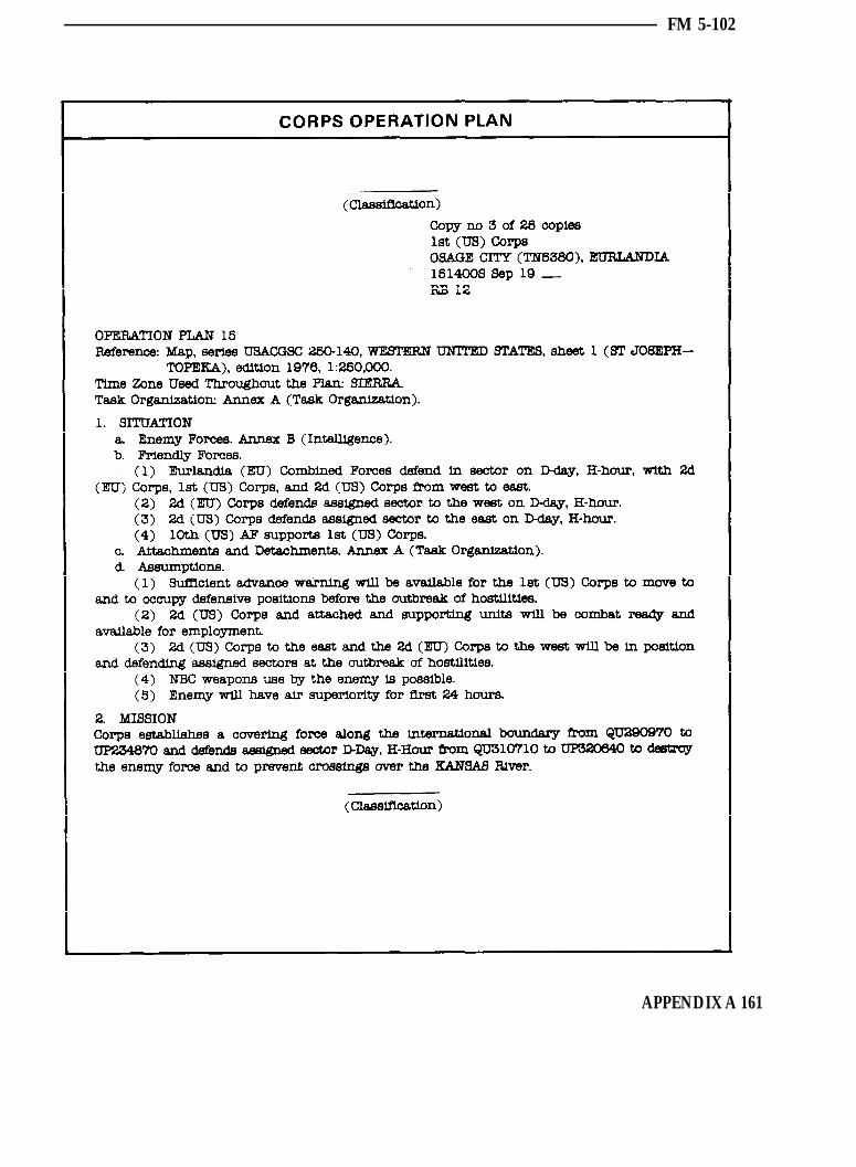
FM 5-102
APPENDIX A 161
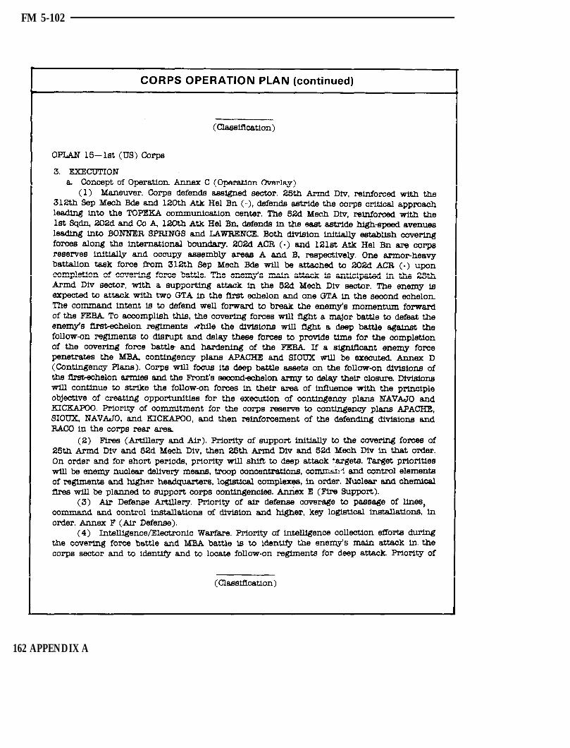
FM 5-102
162 APPENDIX A
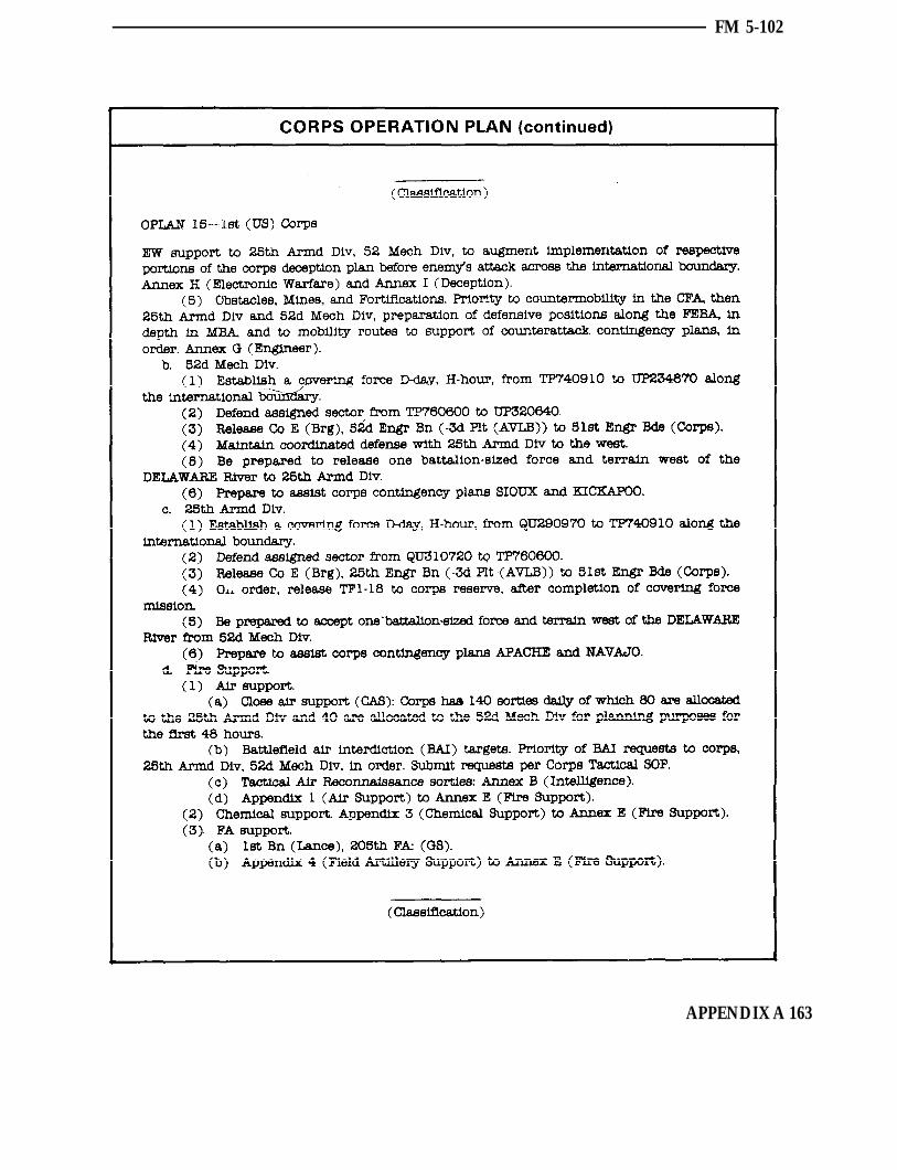
FM 5-102
APPENDIX A 163

FM 5-102
164 APPENDIX A

FM 5-102
APPENDIX A 165

FM 5-102
166 APPENDIX A

FM 5-102
APPENDIX A 167

FM 5-102
168 APPENDIX A

FM 5-102
APPENDIX A 169
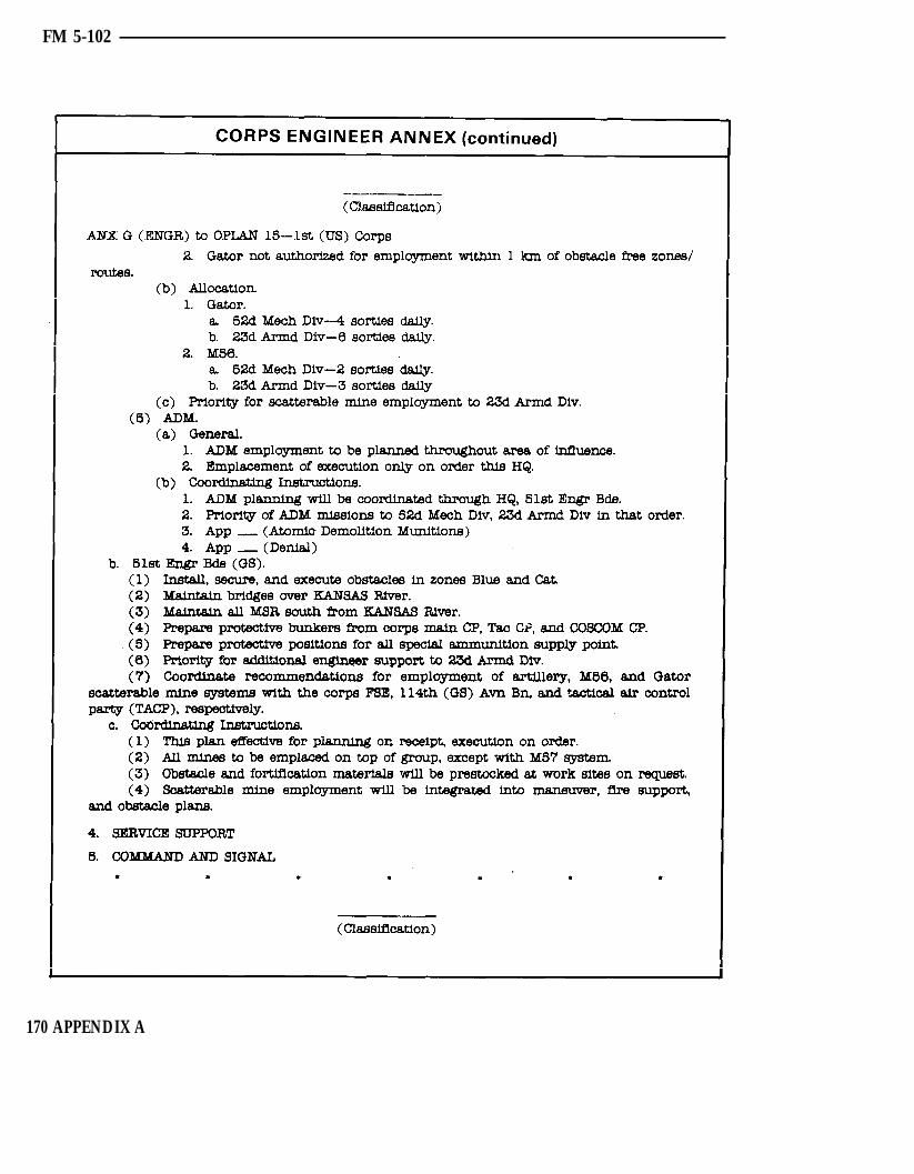
FM 5-102
170 APPENDIX A

FM 5-102
APPENDIX A 171

FM 5-102
172 APPENDIX A
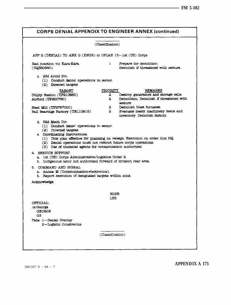
FM 5-102
160-337 0 - 94 - 7APPENDIX A 173

Appendix BSTRONGPOINTS
T his appendix gives insight to develop a strongpoint intothe mission. A strongpoint is the cork in a bottleneck
formed by terrain, obstacles, and units. This countermobility tacticis essentially an antitank “nest” which physically cannot beoverrun or bypassed by tanks, and which can be reduced by enemyinfantry only with considerable expenditure of time and forces. It issimilar to a perimeter defense in that it is developed to defeat anattack from any direction. It is distinguished from other defensivepositions by the key use of terrain and by the time, effort, andresources dedicated to its development.
PLANNING CONSIDERATIONS 175
ENGINEER EFFORTS 176
SCENARIO 177
174 APPENDIX B
FM 5-102
PLANNING CONSIDERATIONS
In some cases, the brigade or division commander may direct that astrongpoint be emplaced by a battalion or company-sized unit. There areseveral important aspects about a strongpoint that need to be clearlyunderstood. A strongpoint is not routinely established. It is established onlyafter the commander determines that a strongpoint is absolutely necessaryto prevent decisive penetration of the defensive system by enemy armor.The decision must be carefully weighed against the following impacts:
If the stronngpoint is bypassed, the defenders may become encircled.
The force establishing the strongpoint loses its freedom to maneuveroutside the strongpoint.
Assignment of this mission presupposes that—
Terrain which lends itself to the mission exists.
Maneuver units and fire support assets required to defend the strongpointare available.
Time, supplies, and equipment necessary for preparation are available.
A strongpoint must be emplaced far enough from the line of contact toprovide the necessary development time. Terrain to the flanks must restrictthe advance of the mounted attacker. The maneuver commander, uponreceiving the mission to establish a strongpoint, immediately conducts ajoint reconnaissance with the leader of the supporting engineer element toestablish the optimum application of available assets. The strongpoint isprepared in accordance with the following broad priorities:
MAKE THE POSITION PHYSICALLY IMPASSABLE TOTANKS.
PLAN INDIRECT FIRES AND SCATTERABLE MINES TOSLOW, DISRUPT, AND CANALIZE THE ADVANCING ENEMY.
ENHANCE THE KILLING POWER OF ANTITANK WEAPONSWITH OBSTACLES.
APPENDIX B 175

FM 5-102
ENGINEER EFFORTS
Building block conceptThe building block approach permits engineer efforts to be planned interms of manpower, equipment, time, and materials for typical emplacementtasks. This concept provides flexibility to the engineer in that estimates canreadily be made for any strongpoint size or design. The building blocks areas follows:
Recon the area with the maneuver commander.
Determine the required effort.
Determine critical tasks.
Allocate resources.
Generally, work from “inside” to “outside.”
Use all available effort.
Essential tasksThe following five essential engineer tasks must be performed for allstrongpoints.
Prepare close-in obstacles to prevent being overrun by tanks.
Prepare hull down positions for fighting vehicles.
Emplace obstacles at maximum ranges of antitank weapons.
Construct protected connecting routes between positions.
Plan and coordinate for scatterable mines.
176 APPENDIX B

FM 5-102
SCENARIO
A brigade consisting of four battalion task forces is defending along acorridor. Its mission is to stop the enemy in sector, and prevent him fromgaining access to the more favorable terrain. The strongpoint must becompleted within 10 hours.
The highway in the valley is the only high-speed approach through thesector. This road is vital to maintaining the momentum of the enemy’sattack, and also vital to his ability to sustain ground operations. Thealternative is to attempt the time-consuming maneuver over restrictiveterrain.
The brigade commander knows that the threat will move its motorizedforces on the high-speed avenue of approach. If the commander fails tocontrol the road, the brigade defense will crumble throughout the sector.The brigade commander determines that a strongpoint is absolutelynecessary to prevent a decisive penetration of the defensive system byenemy armor.
APPENDIX B 177

FM 5-102
The best way to block the enemy is to establish a strongpoint in the valley.The valley is open, flat, and approximately 4 kilometers wide. The hillyterrain on both flanks provides excellent sites for battle positions. The BlauRiver and the marshy areas all along its course further narrow the valley. Asuccession of small villages along the valley floor provides excellent battleposition locations, but fails to fully block the avenue. Near the rearboundary of the sector, only the town of Lingen offers a position whichblocks the valley. In conjunction with the fish hatcheries, the Bazil Burg,and Schloss Wolf, the town forms a chokepoint. It fulfills all the require-ments of a strongpoint for the tactical plan, and can readily be establishedwithin the time constraints. The brigade commander assigns the mission tothe mechanized infantry battalion. The commander of the normally-associated engineer company and the battalion commander made a jointrecon of the area and prepared resource and time estimates.
TasksIn addition to the five essential engineer tasks, the following tasks are alsoperformed for this strongpoint. The tactical commander could vary theseadditional tasks as the situation changes.
Analyze terrain.
Construct other positions that exceed maneuver unit capability.
Improve positions.
Improve obstacles.
The maneuver units can handle the bulk of the preparation of the individualand light crew-served weapon positions, thus allowing the engineers toconcentrate on key positions, the obstacles, and interconnecting routes. TheCombat Engineer Vehicle (CEV) is assigned to work in the town where itsdemolition gun and blade could both be used to create and use rubble forpositions, obstacles, and protected routes between positions.
Although maneuver units are trained in and have demolitions as part oftheir basic load, engineers assist with technical advice in their use. Most ofthe initial demolition work inside the town is done by the maneuver units.The engineer platoon effort, to include demolitions, initially goes intobuilding the obstacle system. When that is finished, the platoon will join themaneuver units in improving positions by using sandbags, rubble, andlocally available building materials to strengthen walls, beams, andoverhead cover. Engineer equipment continues to haul and position earthfor sandbags and other shoring material.
178 APPENDIX B
FM 5-102
Sequence of effortThe maneuver units, assisted by engineers, prepare fighting positions,shelters, and protective obstacles using materials from basic loads. Anengineer squad uses explosives and assists the maneuver units in employingdemolitions and strengthening buildings.
At the same time, the dump truck and loader stockpile earth in eachmaneuver platoon area for filling sandbags, and the dozer and CEV createand handle rubble for obstacles and covered routes. Outside the town, theACE and backhoe/loader digs antiarmor positions and the interconnectingtrenches.
Concurrently, the engineers begin work on the obstacle plan, which wasworked out after a joint reconnaissance by the infantry battalion com-mander and the supporting engineer platoon leader. The plan ties inminefields, bridge demolitions, and road craters with these obstaclesalready present: the town, the sunken road, and the Blau River with itsassociated ponds, marshes, and steep slopes.
The scenario is depicted on pages 180 and 181.
APPENDIX B 179

FM 5-102
180 APPENDIX B

FM 5-102
APPENDIX B 181
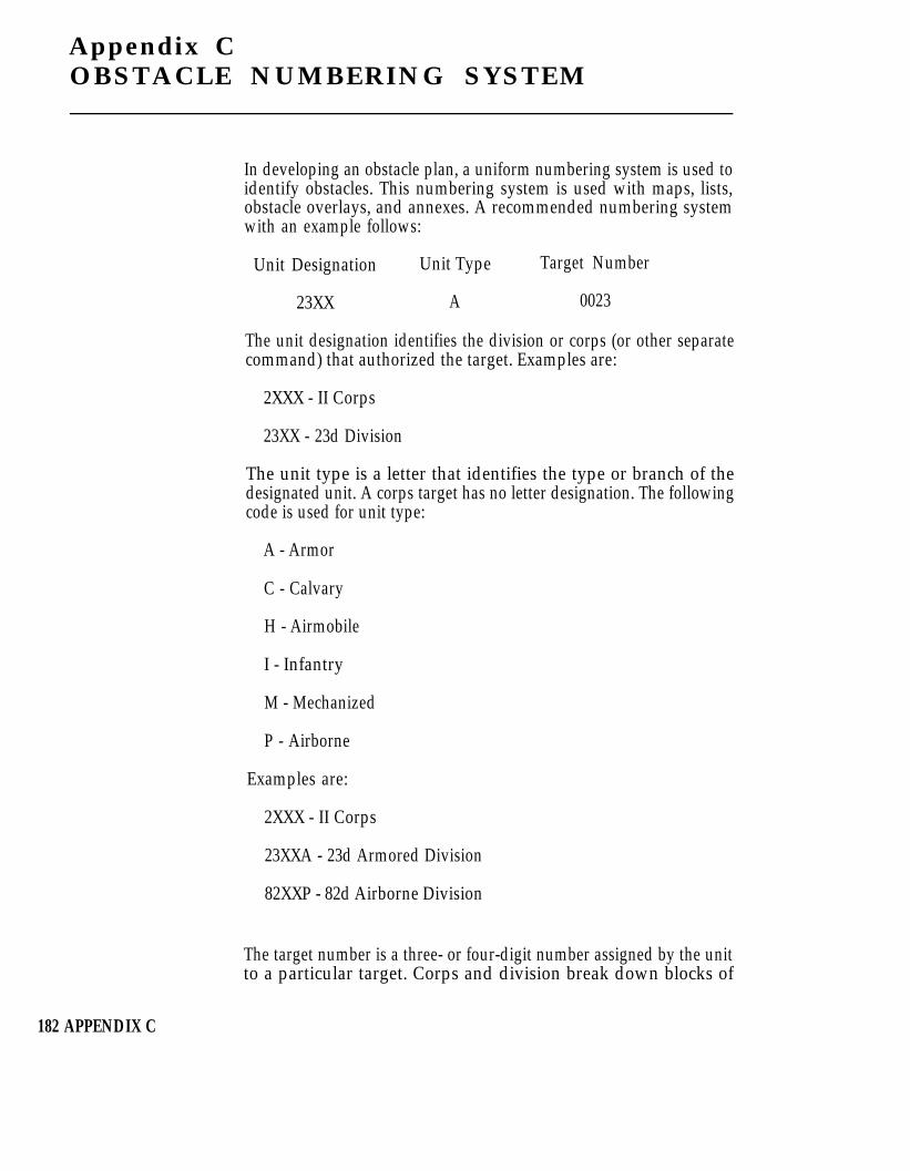
Appendix COBSTACLE NUMBERING SYSTEM
In developing an obstacle plan, a uniform numbering system is used toidentify obstacles. This numbering system is used with maps, lists,obstacle overlays, and annexes. A recommended numbering systemwith an example follows:
Unit Designation Unit Type Target Number
23XX A 0023
The unit designation identifies the division or corps (or other separatecommand) that authorized the target. Examples are:
2XXX - II Corps
23XX - 23d Division
The unit type is a letter that identifies the type or branch of thedesignated unit. A corps target has no letter designation. The followingcode is used for unit type:
A - Armor
C - Calvary
H - Airmobile
I - Infantry
M - Mechanized
P - Airborne
Examples are:
2XXX - II Corps
23XXA - 23d Armored Division
82XXP - 82d Airborne Division
The target number is a three- or four-digit number assigned by the unitto a particular target. Corps and division break down blocks of
182 APPENDIX C
FM 5-102
numbers to subordinate units. Corps uses target numbers 001 through999. The division number system is:
Division uses target numbers 0001 to 0999
1st Brigade uses target numbers 1001 to 1999
2d Brigade uses target numbers 2001 to 2999
3d Brigade uses target numbers 3001 to 3999
(NOTE: Further subdivision of brigade number blocks is notpermitted.)
Target numbers 4000 through 9999 may be assigned to divisional unitsas required, or to other units operating in the division’s area ofresponsibility. Examples are:
2XXX0157 - II Corps, target number 157
23XXA1021 - 1st Brigade, 23d Armored Division, target number1021
It is not necessary to use the complete target number on a division orbrigade obstacle overlay. Within a particular unit, the unit designationand type are dropped. Instead of 23XXA0784, the number 0784 is used.For obstacles authorized or ordered by other units within the sameoverlay, the full target number must be used. The number 2XXX0023would be a II Corps target.
If necessary to distinguish them, denial targets are given a suffix “D”such as 2XXX0057-D.
It is a serious mistake to add any of the following as part of the obstaclenumber. These “add-ons” rapidly reduce the system to unworkability.
Further symbols.
Subordinate number block assignments.
Additional information such as status, target-type location,preparing unit, and relation to a supply facility.
APPENDIX C 183

Appendix DSTANDARD OBSTACLES
T his appendix provides time, personnel equipment, andmaterial estimating factors for obstacle planning.Reconnaissance or experience in a particular area may
require that the planning factors be modified. The estimates givenin this appendix are generally based upon “standard” sizes andtypes of obstacles. The basic purpose of the “standard” obstacleconcept is to permit rapid estimating for resource requirements.Early estimation of resource requirements assists in personnelallocation and early requisition of material to accomplish themission. For instance, if 40 hasty road craters are required in aparticular obstacle plan, multiply the resources required for thehasty crater to get a reasonable estimate of the resources required.The estimates will not always be as accurate as an on-sitereconnaissance; detailed obstacle planning is the most accuratemethod of determing resource requirements.
ARTILLERY DELIVEREDSCATTERABLE MINES (ADAM/RAAMS)
GROUND EMPLACED MINESCATTERING SYSTEM (GEMSS) (M128)
MODULAR PACK MINE SYSTEM (MOPMS)
HELICOPTER DELIVERED AT MINEDISPENSING SYSTEM (M56)
USAF DELIVEREDSCATTERABLE MINES (GATOR)
AT MINE DISPENSING SYSTEM (M57)
CONVENTIONALMINEFIELDS (HAND LAID)
DELIBERATE ROAD CRATER
HASTY ROAD CRATER
CRATERINGDEVICE (M180) WITH MINES
WIRE OBSTACLESABATIS
185
186
187
188
188189
190
191
192
193
193-4
194
184 APPENDIX D
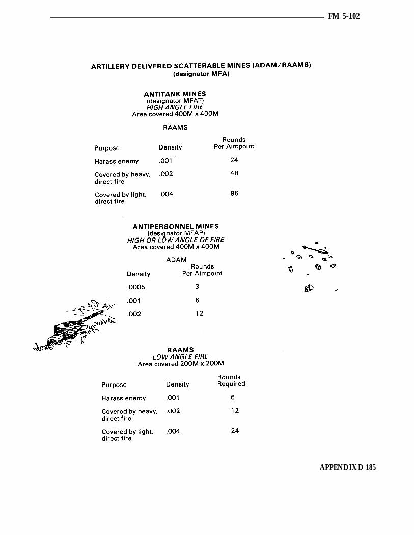
FM 5-102
APPENDIX D 185

FM 5-102
186 APPENDIX D

FM 5-102
APPENDIX D 187
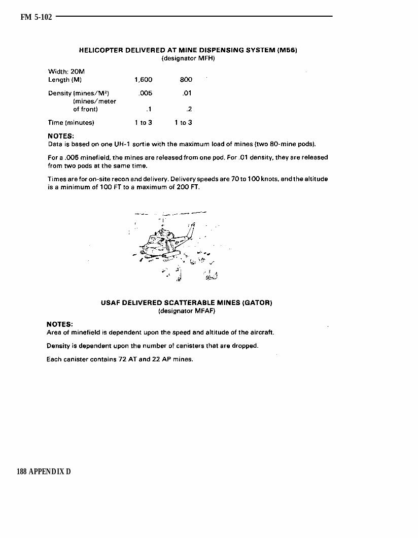
FM 5-102
188 APPENDIX D

FM 5-102
APPENDIX D 189

FM 5-102
190 APPENDIX D

FM 5-102
APPENDIX D 191

FM 5-102
192 APPENDIX D

FM 5-102
APPENDIX D 193

FM 5-102
194 APPENDIX D
Glossary
ACE
ADAM
ADM
AFALOAPAPC
artyATATGM
AVLB
bnBCE
CEV
CFACFC
cm
diaDIA
DMZDTG
eaERAM
engr
Armored CombatEarthmoverArea Denial ArtilleryMunitionAtomic DemolitionMunitionAir Forceair liaison officerantipersonnelArmored PersonnelCarrierartilleryantitankAntitank GuidedMissileArmored VehicleLaunched Bridge
battalionBattlefield CoordinationElement
Combat EngineerVehiclecovering force areaCombined ForcesCommandcentimeter(s)
diameterDefense IntelligenceAgencydemilitarized zonedate-time group
eachExtended RangeAntiarmor Munitionengineer
FFASCAM
FEBA
FLOT
fragFROKA
FSCL
ft
GEMSS
HEMMS
HQhr
ininstIOEIRD
KATUSA
kgkg/cm²
kph
lb
FahrenheitFamily of ScatterableMinesforward edge of thebattle areaforward line of owntroopsfragmentFirst Republic of KoreaArmyfire supportcoordination linefoot, feet
Ground Emplaced MineScattering System
Hand EmplacedMinefield Marking Setheadquartershour(s)
inch(es)instructionsirregular outer edgeInzhenernyRazvedyvatel’ny Dozor(Russian for“engineerreconnaissance patrol”)
Korean Augmentationto the United StatesArmyKilogram(s)kilograms per squarecentimeterkilometers per hour
pound(s)
GLOSSARY 1
FM 5-102
mMBAMETT-T
minmmM O P M S
mph
NANATO
NBC
NCA
NCO
OOD
OPOPCONoz
PLPOL
POZ
psi
meter(s)Main Battle Areamission, enemy, terrainand weather, time, andtroopsmininummillimeter
Modular Pack MineSystemmiles per hour
not applicableNorth Atlantic TreatyOrganizationnuclear, biological, andchemicalnational commandauthoritynoncommissionedofficer
Otriad ObespecheniyaDvizheniya (Russian for“movement supportdetachment”)observation postoperational controlounce(s)
phase linepetroleum, oils, andlubricantsPodvizhnoy OtriadZagrazhdeniya(Russian for“mobile obstacledetachment”)pounds per square inch
pt(s) point(s)
RAAMS Remote Anti-ArmorMine System
recon reconnaissanceROK Republic of Korearpt report
SADM Special AtomicDemolition Munition
SCATMINWARN Scatterable Minefield
SMSOF
SOP
STANAG
TACC
tgtTNTTOE
TOW
TROKA
US
WASPMS
Warningscatterable mineSpecial OperationsForcesstanding operatingproceduresStandardizationAgreement
Tactical Air ControlCentertargettrinitrotolueneTable of Organizationand Equipmenttube-launched, opticallytracked, wire-guidedmissileThird Republic of KoreaArmy
United States
Wide Angle SidePenetrating MiningSystem
2 GLOSSARY

References
REQUIRED PUBLICATIONSRequired publications are sources which users must read in order tounderstand or to comply with FM 5-102.5-100 Engineer Combat Operations100-5 (HTF) Operations (How to Fight)
RELATED PUBLICATIONSRelated publications are sources of additional information. Users do nothave to read them to understand FM 5-102.
Defense Intelligence Agency (DIA) PublicationDDI-1150-13-77 Soviet and Warsaw Pact River Crossing: Doctrine and Capabilities
Department of the Army Form (DA Form)1355 Minefield Record1355-1-R Hasty Protective Minefield Record2028 Recommended Changes to Publications and Blank Forms
Department of the Army Pamphlet (DA Pam)50-3
3-87 (HTF)
5-255-345-355-365-1065-1466-20 (HTF)7-7 (HTF)7-8 (HTF)
7-10 (HTF)
7-20 (HTF)
11-50 (HTF)11-92 (HTF)17-95 (HTF)20-3221-2621-3221-4024-1 (HTF)29-1229-23
The Effects of Nuclear Weapons
Field Manual (FM)Nuclear, Biological, and Chemical (NBC) Reconnaissance andDecontamination Operations (How to Fight)Explosives and DemolitionsEngineer Field DataEngineer’s Reference and Logistical DataRoute Reconnaissance and ClassificationEmployment of Atomic Demolition Munitions (ADM)Engineer Topographic UnitsFire Support in Combined Arms Operations (How to Fight)The Mechanized Infantry Platoon and Squad (How to Fight)The Infantry Platoon and Squad (Infantry, Airborne, Air Assault, Ranger)(How to Fight)The Infantry Rifle Company (Infantry, Airborne, Air Assault, Ranger) (Howto Fight)The Infantry Battalion (Infantry, Airborne, Air Assault, Ranger)(How to Fight)Combat Communications Within the Division (How to Fight)Combat Communications Within the Corps ( How to Fight)Cavalry (How to Fight)Mine/Countermine Operations at Company LevelMap ReadingTopographic SupportNBC (Nuclear, Biological and Chemical) DefenseCombat Communications (How to Fight)Division Maintenance OperationsDirect Support Maintenance Operations (Nondivisional)
REFERENCES 1

FM 5-102
30-530-1071-1 (HTF)71-2 (HTF)71-100 (HTF)90-2 (HTF)90-3 (HTF)90-4 (HTF)90-5 (HTF)90-6 (HTF)90-10 (HTF)90-13 (HTF)100-2-1100-2-2100-2-3101-5101-5-1 (HTF)101-10-1
101-31-1
Combat IntelligenceMilitary Geographic Intelligence (Terrain)Tank and Mechanized Infantry Company Team (How to Fight)The Tank and Mechanized Infantry Battalion Task Force (How to Fight)Armored and Mechanized Division Operations (How to Fight)Tactical Deception (How to Fight)Desert Operations (How to Fight)Airmobile Operations (How to Fight)Jungle Operations (How to Fight)Mountain Operations (How to Fight)Military Operations on Urbanized Terrain (MOUT) (How to Fight)River Crossing Operations (How to Fight)Soviet Army Operations and TacticsSoviet Army Specialized Warfare and Rear Area SupportSoviet Army Organization and EquipmentStaff Organization and OperationsOperational Terms and Graphics (How to Fight)Staff Officers’ Field Manual: Organizational, Technical, and Logistic Data(Unclassified Data)Staff Officers’ Field Manual: Nuclear Weapons Employment Doctrine andProcedures
Joint PublicationTactical Air Command Pamphlet 50-27 and TRADOC Pamphlet 525-43,Joint Operational Concept and Procedures for Coordination of Employmentof Air Delivered Mines (J-Mine)
Training Circular (TC)6-20-5 Field Artillery Delivered Scatterable Mines
PROJECTED PUBLICATIONSProjected publications are sources of additional information that arescheduled for printing but not yet available.
Field Manual (FM)5-101 Mobility5-103 Survivability100-16 Support Operations: Echelons Above Corps’
NOTE: These are publications that are scheduled for printing. Upon print,they will be distributed automatically by a pinpoint distribution and willnot be available for requisition from USA-AG Publications Center,Baltimore, MD, until indexed in DA Pamphlet 310-1.
2 REFERENCES
Index
INDEX 1

FM 5-102
2 INDEX
FM 5-102
INDEX 3

FM 5-102
4 INDEX

FM 5-102
U.S. GOVERNMENT PRINTING OFFICE : 1994 0 - 160-337 INDEX 5

FM 5-102
14 MARCH 1985
By Order of the Secretary of the Army:
JOHN A. WICKHAM, JR.General, United States Army
Chief of Staff
Official:
DONALD J. DELANDROBrigadier General, United States Army
The Adjutant General
DISTRIBUTION:
Active Army, ARNG, and USAR: To be distributed in accordance with DA Form 12-11A. Require-ments for Route Reconnaissance and Classification (Qty rqr block no. 27); Engineer Battalion,Armored, Infantry, and Infantry (Mechanized) Divisions (Qty rqr block no. 28); Engineer Bat-talions, Airborne and Airmobile Divisions (Qty rqr block no. 29); Nondivisional Engineer CombatUnits (Qty rqr block no. 30); Engineer Topographic Units (Qty rqr block no. 32); Landmine Warfare(Qty rqr block no. 151); and Landmine Warfare (Scatterable Mines) (Qty rqr block no. 152).
Additional copies may be requisitioned from the US Army Adjutant General Publications Center r
2800 Eastern Boulevard, Baltimore, MD 21220.

PIN: 057476-000