Embed Size (px)
Citation preview

Field ManualNo. 5-102
HeadquartersDepartment of the Army
Washington, DC, 14 March 1985
FM 5-102
COUNTERMOBILITY
DISTRIBUTION RESTRICTION. This publication contains technical or operational information that is for official Government use only. Distribution is limited to US Government agencies. Requests from outside the US Government for release of this publication under the Freedom of Information Act or the Foreign Military Sales Program must be made to HQ, TRADOC, Fort Monroe, VA 23651-5000.
Table of Contents
Introduction
Chapter 1 -COUNTERMOBILITY ON THE BATTLEFIELD
The Battlefield
Threat Engineers
Countermobility Requirements
Summary

Chapter 2 - COUNTERMOBILITY FUNDAMENTALS
Types of Obstacles
Existing Obstacles
Reinforcing Obstacles
Principles of Obstacle Employment
Summary
Chapter 3 - COMMAND AND CONTROL
Levels of Responsibility
Reserve Obstacles
Summary
Chapter 4 - OBSTACLE PLANS
Planning Considerations
The Planning Process
Offensive Planning Considerations
Defensive Planning Considerations
Retrograde Planning Considerations

Summary
Chapter 5 - MINE WARFARE
Classification
Minefield Employment
Minefield Employment Authority
Reporting, Recording, and Marking
Summary
Chapter 6 - OBSTACLES OTHER THAN MINEFIELDS
Bridge Demolitions
Non-nuclear Craters
Antitank Ditches
Expedient Obstacles
Preconstructed Obstacles
Atomic Demolition Munitions
Summary

Chapter 7 - DENIAL OPERATIONS
Authority and Responsibility
Denial Targets
Denial Methods
Denial Planning
Summary
Chapter 8 - CONSIDERATIONS FOR SPECIAL OPERATIONS
Supporting Light Forces
Special Terrain Environments
Combined Operations
Contingency Operations
Summary
Appendix A - OPERATIONS ORDERS
Appendix B - STRONGPOINTS
Appendix C - OBSTACLE NUMBERING SYSTEM
Appendix D - STANDARD OBSTACLES

GLOSSARY
REFERENCES
AUTHORIZATION LETTER
COUNTERMOBILITY
The foundation for engineer doctrine in the AirLand Battle is built with combined mobility, countermobility, and survivability efforts. This manual provides the basic framework of fielded and developmental countermobility methods, planning, and execution. Its purpose is to integrate countermobility into the overall AirLand Battle structure.
Countermobility support is divided into mine warfare and obstacle development, each with an ultimate goal of delaying, stopping, or channelizing the enemy. Mine warfare expands to include mine categories, methods and systems of delivery, employment, reporting, recording, and marking. Obstacle development demonstrates innovative techniques and conventional improvements in planning and emplacing obstacles other than minefields.
Countermobility effort is not secluded; rather, it balances with the other major battlefield missions of mobility and survivability, as well as general engineering and topography. The overall teamwork and planning process are both evident and essential with each facet of countermobility.
STANAG IMPLEMENTATION
The provisions of this publication are the subject of the following international Standardization Agreements: STANAG 2017, Orders to the Demolition Guard Commanders and Demolition Firing Party Commander (Non-Nuclear); STANAG 2036, Land Minefield Laying, Recording, Reporting and Marking Procedures; STANAG 2096, Reporting Engineer Information in the Field; STANAG 2123, Non-Nuclear Demolition Target Folder; and STANAG 2889, Marking of Hazardous Areas and Routes Through Them.
USER INFORMATION
Users of this manual are encouraged to submit recommended changes to improve the manual. Comments should identify the area in which the change is recommended. Reasons should be provided for each comment to allow complete evaluation. Comments

should be prepared using DA Form 2028 (Recommended Changes to Publications and Blank Forms) and forwarded directly to the Commandant, US Army Engineer School, Fort Belvoir, VA 22060-5291.
When used in this publication, "he," "him," and "his" are used to represent the enemy.
Chapter 1
COUNTERMOBILITY ON THE BATTLEFIELD
This chapter focuses upon a modern battlefield against an enemy using Soviet style tactics and organizations. It discusses the modern battlefield, emphasizes threat operational concepts, particularly threat engineers and their capability to provide countermine and counterobstacle support to the offense, and covers the importance of friendly countermobility activities to deny the threat freedom of movement.
THE BATTLEFIELD THREAT ENGINEERS
COUNTERMOBILITY REQUIREMENTS

SUMMARY
THE BATTLEFIELD
The most dangerous threat to United States' (US) national interests will most likely involve highly trained enemy forces using Soviet style tactics, organizations, and equipment. The actual battle will be intense, fast, and deadly. United States forces must therefore be prepared and trained to fight on a future battlefield where--
• Highly mobile forces will use combat systems delivering firepower of unprecedented volume, speed, accuracy, range, and lethality.
• Airspace will be crowded with aerial combat, surveillance, transport, reconnaissance, and target acquisition systems.
• Communications systems will be the target of indirect fire and sophisticated electronic warfare operations, making command and control difficult to achieve and maintain.
• Scatterable mine systems will severely affect ground mobility due to rapid and remote delivery means.
• Employment of nuclear, biological, and chemical (NBC) weapons will create anew experience and add new dimensions to the environmental conditions.
Ultimate success on the battlefield will depend on mobility and countermobility efforts, not only near the forward line of own troops (FLOT), but also in rear areas. Successful commanders will need to concentrate forces at the decisive time and place, make maximum use of unit versatility, exercise movement and maneuver, impede the opposing force's movement and maneuver, and preclude enemy reinforcement of committed units and their resupply.
THREAT ENGINEERS
Engineers play a vital role in the success of threat army combined arms operations. In the threat view, the greater the increase in mobile warfare, the greater the need for passable terrain. Therefore, stated in simple terms, the mission of the threat combat engineers is to keep the offense moving. Threat engineers are organized, equipped, and trained to accomplish this mission under fire and in all environments including NBC.
ORGANIZATION
All tank and motorized rifle units down through the regimental level have organic engineer elements. In combat, these elements form special engineer combat groups--either under control of parent command or attached to subordinate commands--to perform direct support missions. Engineer elements are also combined with other branch elements in operational groupings to perform specific tasks. At higher echelons (Front or Combined Arms Army), considerable engineer reserves are maintained either for concentrated use as needed, or for attachment to subordinate formations. This reserve allows rapid switching of engineer effort from one area to another, affording maximum

tactical and operational flexibility. Furthermore, it is not unusual for the senior formation commander to strip a unit of its engineer element when that element is required for a concentrated effort elsewhere on the battlefield.
Doctrine emphasizes that commanders at all levels must strive for maximum flexibility in using engineer assets, inasmuch as engineer tasks are not isolated but are part of the overall tactical plan.
Combat engineer units at any level are of two general types: engineer special/technical units or general purpose engineer units.
Special/technical units perform the following tasks:
• Engineer reconnaissance. • Road and route preparation. • Field fortification construction. • Bridge construction. • Camouflage. • Assault river crossing. • Obstacle construction and/or removal. • Minefield breaching and clearing. • Water supply.
General purpose engineers may perform any or several of the above tasks, but usually to a lesser degree than their special/technical counterparts. In either case, the threat envisions that most if not all of these tasks are conducted under fire or well in advance of main assault elements.
Technical repair of pipelines and topographic surveying are not the responsibility of threat engineer units. In addition, many simple and general engineer tasks are not carried out by engineer soldiers, but by soldiers of other combat arms. For example, all threat combat soldiers are expected to be proficient at mine clearance. The operation of tank-mounted mine plows and rollers is a responsibility of armored forces, although engineer advice is available in deciding whether to employ such devices.
The organization of threat engineer units is the result of careful study and is designed to accomplish specific objectives. These objectives are:
• Conducting engineer tasks necessary to support the tactical employment of other combat arms, especially the movement of tank and motorized rifle elements.
• Attaching additional engineer assets to subordinate elements and maintaining a significant engineer reserve.
• Dovetailing and expanding engineer tasks in the offense by follow-on engineer elements of increased capabilities.
• Providing cohesion to the defense and security in the offense by employing mines, obstacles, field fortifications, and antitank defenses.
The structure of engineer units is constant at the regimental and divisional levels, but not at higher levels of command. The engineer units assigned to a Front or Combined Arms Army will vary with the level of importance of the major command in the overall operational or strategic plan. Generally, a Front engineer reserve is likely to be twice as

large as that of a Combined Arms Army.
PRINCIPLES OF THREAT ENGINEER EMPLOYMENT
Threat military principles are observed in order of precedence. To a certain extent, threat military principles appear as rephrasing of Western principles of war. However, applying these principles is peculiar to threat military theory, and threat units are configured and equipped to attain them. These eight military principles, in order of priority, are:
1 Mobility and high rates of combat operations.
2 Concentration of main efforts and creation of superiority in forces and means over the enemy at the decisive time and place.
3 Surprise and security.
4 Combat activeness (constant combat and pressure).
5 Preservation of the combat effectiveness of friendly forces.
6 Conformity to the goal.
7 Coordination.
8 Action upon the enemy to the entire depths of his employment and deep into his rear area.
These principles are basic to a threat officer's approach to any combat problem, and will have a profound effect on any decision made. For example, achievement of high speed in the execution of combat missions is the first principle, and will therefore take precedence over the need to avoid casualties and preserve the combat effectiveness of friendly troops. In other words, saving time is more important than saving lives, since fewer lives would be lost if the threat commander is allowed to exercise battlefield initiative and dictate the terms of combat. While adhering to these principles, the role of combat engineers is to assist other elements of combat arms to follow them more closely, thereby attaining greater combat effectiveness.
The threat has certain principles peculiar to combat engineers. These principles are binding upon the engineer commander and state that combat engineer operations must--
• Correspond to the impending battle concept and support the commander's plan. • Be completed in time to allow the completion of tactical activities necessary in
implementing the plan. • Be concealed to deprive the enemy of intelligence indicators. • Contribute directly to the effect of the main attack in the offense or the main
sector in the defense. • Be capable of rapid maneuver to adapt to changing battlefield situations. • Deceive the enemy regarding the direction or location of the main effort.
THREAT ENGINEER SUPPORT OF THE OFFENSE
In the offense, the chief function of engineers is to assist in maintaining high rates of

movement, which is the premier tactical principle of threat military doctrine. Emphasis is placed on clearing and maintaining routes for the advance of combined arms units, to include breaching or removing mines and obstacles, crossing water obstacles, and assisting in flank protection or protection against counterattack. Engineer reconnaissance, independently or in collaboration with other reconnaissance means, plays a significant role in facilitating movement. Camouflage and protection during halts or temporary assumption of the defense are also basic engineer functions.
Secondary attention is given to supporting logistic operations in rear areas. The practical effect of these engineer requirements is to create certain key functions which must be satisfied by engineer troops. These functions include:
• Engineer reconnaissance. • Movement support. • Mine and countermine warfare. • Wet and dry gap crossings.
Engineer reconnaissance
The goal of engineer reconnaissance is to provide a comprehensive report on the passability of march routes. Engineer reconnaissance is conducted by engineer elements attached to combined arms or reconnaissance units, or by engineer officers acting as part of the commander's reconnaissance party which checks the validity of plans made from intelligence without actual prior inspection of the terrain. Engineer elements performing this reconnaissance must determine--
• The degree of passability of the entire route. • The location and nature of obstacles to be overcome and the engineer assets
required to overcome them. • The condition of all crossing sites, wet or dry. • The location and quantity of material which can be used to improve the march
route. • The nature of the terrain and location of areas with natural concealment.
In the conduct of engineer reconnaissance, the most commonly employed formation is the Soviet engineer reconnaissance patrol, Inzhenerny Razvedyvatel'ny Dozer (IRD). The IRD may vary in strength from a squad to a platoon. Commanded by an officer or senior noncommissioned officer (NCO), it is equipped with the necessary equipment for accomplishing its task. The IRD will almost always be vehicle-mounted, utilizing the reconnaissance version of the BRDM or BTR60. The commander is issued maps and aerial photographs of the march route and provided with the column composition indicating the number and types of vehicles the route must accommodate.
Significance to Friendly Forces
The appearance of engineer reconnaissance elements serves as an important intelligence

indicator of impending offensive action. In addition, since engineer reconnaissance is normally conducted one to one-and-a-half days in advance of the main force's movement, it provides highly valuable information regarding the timing of threat activity. Since threat offensive tactics are predicated upon high rates of movement and engineers are paramount in implementing this movement, friendly counterreconnaissance action directed against IRDs will deprive the threat commander of engineer intelligence vital to executing the tactical plan. Finally, the documents carried by the IRD commander provide portions of the threat commander's actual tactical plan.
When in close proximity to enemy forces occupying prepared defensive positions, threat engineer reconnaissance will be conducted in a different manner than when it supports an approach march. In such an instance, existing intelligence concerning roads, topography, defenses, and the like, will be initially supplemented by aerial photography and aerial visual reconnaissance. Engineers will be attached to many combined arms reconnaissance elements. The IRDs will be employed to penetrate defenses to reconnoiter either a specific avenue of approach or particular defensive fortifications and obstacles. Additionally, reconnaissance may be conducted by establishing covert engineer observation posts close to, or actually within, the defensive sector.
One engineer observation post (OP) is normally established per 2 kilometers of front in order to observe the entire enemy FLOT and ascertain the engineer action and equipment necessary to properly support the attack. As the attack progresses, these OPs continue to observe the effectiveness of the engineer assault and make recommendations concerning alteration of the operation plan or commitment of the engineer reserve. The purpose of engineer reconnaissance is to develop intelligence supporting the employment of first echelon assault elements. The value of denying engineer information through aggressive counterreconnaissance cannot be overemphasized. Since assault engineer tasks are a prerequisite to the execution of the threat commander's tactical plan, any friendly action which interferes with these tasks will concurrently degrade the execution of the plan.
Movement support
The threat army believes that, without adequate engineer preparation, the approach march is sometimes not possible at all. Therefore, the results of engineer reconnaissance serve two purposes:
1 Selecting column routes which require the least engineer preparation.
2 Planning the employment of engineer assets for any route clearing needed.
Principles of movement Considering the results of engineer reconnaissance and the tactical requirements of the operation plan, the commander selects the unit's approach route. The Chief of Engineer Services then drafts the engineer plan for movement support. This plan is based upon two principles:
1 Engineer soldiers must be equitably dispersed throughout the march column to insure proper engineer support to the entire formation.
2 Engineer soldiers must work as far in advance as possible.

Threat doctrinal texts state that movement support elements should ideally operate one-half day in advance of the main force. The manual task of route preparation usually falls to a temporary organization called a movement support detachment, Otriad Obespecheniya Dvizheniya (OOD). Several OODs can be formed from the engineer battalion of the tank and motorized rifle division, while additional OOD assets exist in the engineer companies of the tank and motorized rifle regiments.
Responsibilities of the OODs Specific responsibilities include the following:
• Clearing and leveling areas of movement. • Building approaches and exits at streams, ravines, or other obstacles. • Constructing bypasses. • Breaching and clearing mines. • Marking routes.
The organization of the OOD may vary depending on the scale of work undertaken and the assets available. In general, the faster the desired rate of advance, the stronger the OOD. In most if not all cases, the OOD will be reinforced with tank and motorized rifle elements to assist engineers in those tasks conducted under fire. Typical variations in the structure of OODs are shown in the following illustration. The groups are organized having the following missions:
• Reconnaissance and Barricade Destruction Group: Reconnoiters march route, clears obstructions, and selects column route.
• Road and Bridge Group: Prepares route and provides crossings. • Route Marking Group: Marks route and provides security and traffic control

Moving into position directly behind the division's advanced guard, or sometime behind the advanced guard's point security patrol, the OOD normally moves about 1 to 2 hours in advance of the head of the march formation. A typical sequence of activities for an OOD would consist of:
• The reconnaissance and barricade destruction group reconnoiters enemy minefield and obstacles protecting a river crossing. Obstacles are cleared by engineers using explosives, while plow and roller-equipped tanks clear lanes. through the minefield. Using information previously obtained by an IRD, additional reconnaissance of the river banks is conducted to determine the exact extent of preparation necessary for bridging. Enemy troops in the area are engaged by tank and motorized rifle elements.
• Road and bridge groups improve initial lanes through minefield, prepare banks for bridging equipment, and emplace bridges.
• As preceding groups continue movement, the route marking group emplaces required route and bridge markers, establishes traffic control points, and regulates traffic flow until relieved by military police traffic units.
• The threat uses smoke and supporting indirect fire as necessary to assist the OOD in accomplishing required tasks.
Threat doctrine for route preparation stipulates that, as an average, a divisional engineer

battalion should be able to prepare up to 100 kilometers of route per day in open country where roads or tracks have not been subjected to specific enemy action to block or destroy them. If the route has been specifically interdicted by the enemy, then only 20 to 40 kilometers per day can be achieved, less if the engineer tasks must be conducted under fire, In such cases, it is common for threat engineers to construct a rough track parallel to the planned route, if possible, in order to maintain the tempo of the advance.
Significance to Friendly Forces
Threat offensive operations are predicated upon high speed execution and the sequenced arrival and departure of combined arms teams at specific locations at designated times. Thus, dependent upon an exceptionally high degree of coordination, the threat commander relies to a critical extent upon the movement support activities of his engineer troops. Action which denies the accomplishment of engineer route preparation activities may create a potentially disastrous situation for the threat commander. The delay of an advancing column by an unexpected obstacle not only disrupts coordination and slows the tempo of battle, but also causes succeeding units to combine with those in front, creating a highly rewarding target for friendly fires.
Mine and countermine warfare
In the threat view, the most important features of mines are speed and ease of emplacement on the battlefield. Emplacing a mine belt is considered much more effective and efficient against infantry and tanks than trenches, wire, or other fortifications. Mines are a much quicker means of erecting a defense. Consequently, they are widely used even in offensive operations. In supporting the offense, engineers employ extensive minefield in several situations such as--
• When temporarily assuming the defense. • When protecting against counterattack. • When providing flank protection.
In any future war, the threat believes there will be no distinct front line nor a clearly defined forward edge of the battle area (FEBA) or FLOT. Rather, there will be a series of offensive and counteroffensive axes in the form of spurs and salients. Given the fluidity of combat under such conditions, a mine obstacle offers far greater flexibility in employment than antitank ditches, tetrahedrons, and other such relatively static obstacles. Minefield will be the most common means of protecting vulnerable aspects of offensive deployment, and mined areas may be expected to be far greater than those encountered in World War II. Although all threat troops are trained in the fundamentals of mine warfare, combat engineers are specially trained to perform this function. The primary combat engineer element performing mine warfare support for the offense is a temporary organization called a mobile obstacle detachment, Podvizhnoy Otriad Zagrazhdeniya (POZ), which is formed from elements of regimental and divisional combat engineers.
In the offense, POZs are positioned on the flanks of the march column, and usually are

closely associated with the antitank reserve. Each POZ will be equipped with up to three PMR-3/60 minelaying trailers with towed mine-carrying vehicles, or the newer GMZ tracked armored mine-laying vehicle which is rapidly replacing the older PMR-3/60. In certain instances, the Mi-8/HIP helicopter with removable mine racks and chute dispensers may be used to emplace mines from an altitude of about 5 meters. A divisional POZ equipped with the GMZ tractor is capable of emplacing a 1,000-meter minefield containing 750 to 1,000 mines at 4-or 5.5-meter intervals within 30 minutes on suitable ground.
Temporary assumption of the defensive If the attack fails, engineers must be prepared to conduct rapid fortification and obstacle activity in support of the hasty defense. In this role, POZs will perform as they do in offensive combat and emplace mines in accordance with the overall defensive plan.
Protection against counterattack In planning the offensive employment of the command, the threat commander constantly evaluates the battlefield for suitable enemy counterattack areas. Areas identified as favorable are usually those which would detract from the maneuver of the combined arms teams, and be considered vital for mine employment in order to deny the enemy commander tactical initiative.
Flank protection Engaging in a battle of dispersion and maneuver necessarily creates extensive exposed flanks. In threat theory, preventing enemy exploitation of such a condition relies, on two actions: rapid execution of combat tasks before the enemy can react, and protection of flanks by extensive minefield. During the march to contact and during the engagement itself, POZs actively emplace mines on the flanks of maneuvering units to preclude being attacked by mobile forces of the enemy.
In the late 1960s and early 1970s, the tendency for a POZ to create an obstacle by alternating minefield with other antitank obstacles along a 6- to 7-kilometer front is now considered ineffective, as is the practice of laying long strip minefield without covering them by antitank fire. Current threat teaching stresses the need for anititank guns to engage tanks as soon as they encounter the minefield. Thus, a short, deep mine and gun obstacle belt is preferred to a long, thin one, making choice of position critical.
Because of the possible need to recover minefield as the advance progresses, antipersonnel mines are rarely included in an antitank minefield laid in support of offensive operations. Minefields left behind are clearly marked and recorded, and their locations are reported to the Chief of Engineer Services.
Significance to Friendly Forces
In the offense, the commander employs mines in areas evaluated as offering the enemy a significant advantage to interfere with the tactical plan. Thus, the detection of minelaying activity offers the friendly force an indication of the manner in which the threat command

will be employed, and highlights those areas deemed critical to success.
The threat, in planning for the widespread employment of mines, fully expects any enemy to engage in extensive mine warfare. Consequently, countermine warfare is an extremely important task entrusted to combat engineers. Breaching lanes through enemy minefield is critical to the goal of keeping the attack moving. Equally important is the desirability of conducting mine breaching operations covertly, whenever possible, to preserve surprise. When attacking from the march, the location of enemy minefield is the responsibility of engineer reconnaissance patrols (IRDs). The IRD is equipped with several types of mine detectors, the most common being the DIM metallic mine detector mounted on the UAZ 69, 1/4-ton, 4 x 4 Light Utility Vehicle. The DIM is synchronized with the vehicle's ignition system and, upon detecting a metallic mine, cuts out the electrical system and kills the engine. The IRD reconnoiters the limits of the minefield and marks it for the following movement support detachment (OOD).
In breaching the required number of lanes through the minefield, the OOD will employ several types of mine breaching equipment. The normal threat method of breaching minefield during an assault or rapid advance is to employ mine plows fitted to the lead tanks. Although engineers will reconnoiter the minefield, the initial breaching is not primarily an engineer task. The KMT-4 and KMT-6 plows are normally employed on the scale of one per platoon of three to four tanks. Engineers assist in fitting these and plow-roller combinations (KMT-5s) commonly used for minefield reconnaissance. The threat estimates clearing speeds of about 6 kilometers per hour (kph) for plow-fitted tanks, and about 10 kph for roller-fitted tanks. Combat vehicles follow these plow-equipped tanks in the breaching of a minefield. The threat employs a mine-clearing device mounted on the BTR-50 PK Armored Personnel Carrier (APC) (two to each divisional engineer battalion). This device fires and then detonates an explosive hose (line charge) across the minefield. It clears a lane about 180 meters long by 6 to 8 meters wide. This equipment is particularly useful during an assault river crossing when there are minefield on the far bank and amphibious vehicles may have to initially operate in the bridgehead without tank support.
Another mine-clearing device is the explosive line charge. It consists of three separate linear charges, a nose section, and a detonator box. Each linear charge may be assembled to any desired length by connecting 2-meter sections together with threaded collars. The light, sheet metal, 5-centimeter-diameter, tubular sections are filled with cast trinitrotoluene (TNT) explosive at 9 kilograms per linear meter. This device is versatile in that it may be used as a single, double, or triple charge. The forward end section is fitted with a roller to facilitate insertion of the charge into a minefield. The device is assembled in a rear area, towed by tank to the minefield's edge, pushed into the minefield, and fired. The triple line charge will clear a 6-meter-wide path along the entire length of the charge. A squad can assemble a 500-meter-long triple charge in 1 to 1.5 hours.
Bangalore torpedoes are also used. Sections, 2 meters in length, carrying 6 kilograms of explosive, are connected by collars. The clearance depth of a path 1 to 2 meters wide is limited only by the manageable weight that can be manually pushed into the minefield.
The number of lanes to be cleared depends on the terrain and the number of columns in the assault echelon. For a leading battalion in the assault on a main axis, six to eight lanes

may be required, one for each assaulting platoon. In secondary sectors, as few as two lanes may be sufficient. However, an average of four to six lanes can be expected with at least two developed into permanent lanes, 6 to 8 meters wide, for passage of artillery and logistic vehicles. Engineers mark minefield lanes and provide traffic control through the minefield. The routes leading from a start line to each lane are marked with red triangular metal flags and black-and-white tapes. Illuminating markers may be used at night. Routes through friendly minefield are marked by signs of various shapes placed not less than 20 meters apart on both sides of the route. If possible, they are positioned so as not to be visible from enemy positions.
In attacking from line of march, manual mine breaching is carried out only under certain conditions:
• As nuisance minefield along or on routes, especially around craters and demolitions, to allow the route clearing unit to work freely.
• On approaches to water obstacles and water mines. • To maintain surprise, especially at night or when the threat wishes to make a gap
in their own minefields. • When other mine breaching equipment is committed.
When conducting assault breaching operations against a defended enemy minefield, the usual practice is to attack with combined arms teams led by combat engineers and supported by artillery and tactical aviation. Such a formation is necessary if the combat engineers are not to suffer crippling losses to defensive fires. Artillery, in particular, plays a major role in suppressing defensive fires and allowing the execution of engineer tasks. If artillery support is not available or is too short in duration, the first wave of the attack is led by plow-and roller-equipped tanks, while combat engineers closely follow to widen lanes. Here again, the use of plow-and roller-equipped tanks is not an engineer responsibility, but an engineer function carried out by tank soldiers. Another means of lane improvement entails mine clearing tanks dragging a variable length of explosive line charge. The charge is detonated to clear mines not uncovered by the plow or roller. Our minefield should be deep enough to preclude the threat from breaching the entire depth with one line charge. The threat breaching capability with one line charge is curently in the 50-meter range. A threat squad can assemble a 500-meter-long triple charge in 1 to 1.5 hours by coupling the 50-meter sections together. Planners should check the current threat capability for breaching before determining what size minefield is most effective.
As with much of threat engineer activity, threat mine and countermine operations provide both intelligence and tactical values to friendly forces. Minefield breaching activity is indicative of impending threat offensive action, and the identification of such activity will greatly assist in determining times and locations of attack. However, it must be kept in mind that threat doctrine calls for the conduct of bogus mine clearing activity as part of cover and deception plans. Tactically, the denial of threat countermine actions serves to deprive the threat commander of the tactical initiative which his entire operation plan is based.

River crossings
Threat military doctrine dictates that, whenever possible, water obstacles along a broad front are crossed at multiple points without pause in the march or the advance. This tactic is designed to rapidly overwhelm enemy defenses and maintain the tempo of the attack. In the threat view, a delay at a major water obstacle can jeopardize the success of an entire offensive operation in conventional combat, and is certain to destroy large forces massed for the crossing during a nuclear war. Consequently, the threat recognizes two distinct forms of river crossing, hasty and deliberate.
Hasty crossing The hasty crossing incorporates the features of rapid movement previously mentioned. The attacking force crosses the water obstacle in stride, does not stop to consolidate bridgeheads, and continues the advance without pausing. This is the preferred form of river crossing.
Deliberate crossing The deliberate crossing is conducted when an attempted hasty crossing has failed, or when hostilities are being initiated against a well-prepared enemy occupying a river line defense. It is characterized by more detailed planning, extensive buildup and preparation, and a greater degree of centralization than the hasty crossing.
The role of combat engineers in both types of crossing is critical. While all arms are fully trained in their individual roles in river crossing operations, engineer functions provide the margin of success. It is not the purpose of this section to examine river crossing operations in their entirety, but to define the role of engineers within the overall effort. For a complete account of the conduct of river crossing operations by all arms, see Defense Intelligence Agency (DIA) Publication DDI-1150-13-77.
Engineer support to assault river crossings by threat forces occurs in the following areas:
• Engineer reconnaissance of water crossings. • Route and site preparation. • Crossing preparation and execution. • Site protection. • Support to units within the bridgehead.
Engineer reconnaissance of water crossings In the threat view, the key to a successful river crossing is thorough reconnaissance to determine both the tactical situation and the technical characteristics of the river and its banks. As a general principle, reconnaissance will be carried out across a wide front to avoid focusing enemy attention on one area. Additionally, this activity identifies the numerous crossing sites needed to support the crossing of widely dispersed units. Engineer reconnaissance personnel will attempt to ascertain the following information at each site:
• River width, depth, and current. • Entry and exit gradients. • River bottom composition.

• Bank composition and height. • Approach and exit routes. • Critical terrain features dominating both banks. • Possible fording, ferrying, bridging, and snorkeling sites. • Information on enemy defenses.
In obtaining this information, engineers may, as in other offensive operations, accompany combined arms reconnaissance teams; or, engineer patrols (IRDs) may operate independently. An IRD will usually operate from the BRDM engineer reconnaissance vehicle and will be equipped with a variety of reconnaissance equipment. In some instances, engineers are clandestinely dropped by parachute directly on the water obstacle.
A typical reconnaissance mission for a squad-size IRD might require the reconnaissance of two sites in a 500- to 600-meter sector, a task usually accomplished in 4 hours. Scuba-equipped engineers check for water mines and test riverbed conditions. Other members of the IRD select and mark concealed approach routes; obtain hydrographic data by using depth finders and water current meters; determine river bank conditions and the presence of existing or military obstacles; identify enemy defenses and conduct bogus reconnaissance activity in other areas to avoid disclosing the main crossing sector.
Significance to Friendly Forces
Engineer reconnaissance performed in support of water crossings has both intelligence and tactical value to the friendly force. Conducting engineer reconnaissance will assist in identifying planned crossing sites for combined arms teams and the times of attack. Such information is of extreme importance in planning the friendly tactical response. Counterreconnaissance, which prevents the accomplishment of engineer reconnaissance missions, deprives the threat commander of information vital to the successful execution of attack.
Route and site preparation Route preparation of approaches to crossing points will follow the same procedures as in the approach march. Movement support detachments (OODs) will accompany the vanguard elements of advance forces to provide trafficable conditions for the types and numbers of vehicles in the column. A division will usually cross a river on a wide front at a minimum of four points (sometimes up to eight) simultaneously, seeking to find suitable areas for each type of crossing means. This requires the engineer staff to carefully plan and allocate engineer assets.
The preparation of proper entry and exit bank gradients is crucial and depends upon the results of the reconnaissance effort. Earthmoving equipment and explosives are used in preparing bridge approaches and entry and exit points at ford, ferry, and swim sites. Rapid execution of these tasks is essential, since the actual crossing units follow closely behind and depend on suitably prepared crossing points before commencing operations.

Significance to Friendly Forces
Site preparation is a critical phase of a threat river crossing operation. Interference with site preparation activity translates directly to interference with the sequence and timing of the engineer effort, which the entire crossing is dependent upon. If the site preparation effort can be denied, the following crossing units will either be unable to perform their function or forced to halt. The tempo of the attack will be disrupted, and the consequent bunching of units will create lucrative targets. For these reasons, site preparation represents the most vulnerable aspect of a threat river crossing.
Crossing preparation and execution Following the initial site preparation, and immediately prior to actual crossing, final preparatory activities are executed. Previously located water mines are destroyed by scuba-equipped engineers using explosives. Where necessary, metal matting is emplaced at soft bottom fords. Engineers in amphibious APCs accompany initial assault waves and assist in reducing defenses on the far bank.
During the actual crossing, the ferry operation and bridge emplacement are solely engineer functions. Additionally, engineers are responsible for traffic control and direction at all crossing sites. In the latter role, engineers insure that the crossing is conducted at a high rate of speed, a requirement considered to be extremely important. Threat doctrine establishes the desired crossing time for the division combat elements as 3 hours during daylight and 6 to 8 hours at night.
Significance to Friendly Forces
The primary role of engineers during this phase is providing the physical means by which the bulk of the division crosses. This phase of engineer operations also marks the arrival of major combined arms teams, and is usually supported by artillery fires. In most cases, it will be conducted under the protection of the air defense umbrella.
Site protection Commencing with initial site preparation and continuing through the conduct of the crossing, engineer elements are responsible for protecting the site, equipment, and combined arms teams from floating mines and enemy raids. Scuba divers and power boats will constantly patrol both upstream and downstream approaches to the crossing site, and outposts will be established along likely land approaches.
Significance to Friendly Forces
When planning raids against threat gap-crossing sites, the presence and locations of these security forces already established by prior reconnaissance should be considered.
Support to units within the bridgehead

As the threat force establishes itself on the opposite bank, elements of the engineer reserve accompany combined arms teams in performing engineer tasks necessary to keep the advance moving. In this role, engineers function in the same manner as when supporting the attack from the line of march or when in contact with the enemy. The crossing site will gradually become the responsibility of lines of communication troops, and the combat engineers will rejoin the division and be prepared to support the next crossing operation.
Significance to Friendly Forces
As with other threat engineer activity, the shift of engineer emphasis accompanies a shift in tactical emphasis. Friendly action which destroys or damages bridging and ferrying equipment during this phase will reduce the threat ability to conduct subsequent river crossings until equipment is replaced.
COUNTERMOBILITY REQUIREMENTS
In order for the threat to attain its primary military principle, Mobility and High Rates of Combat Operations, it is imperative that they preserve their ability to move and maneuver on the battlefield. Threat forces are designed, organized, trained, and equipped to accomplish this principle above all others.
Friendly US countermobility tasks must therefore be designed and executed to slow the movement rate specified by the threat. The use of countermobility by friendly forces must be integrated into the concept of operations not only to impede threat mobility, but to increase the kill probability of friendly firepower. Obstacles must be sited to reinforce the terrain and maximize the effective firepower from friendly battle positions.
Countermobility operations will be used along the FLOT as well as deep into the threat rear area. The use of scatterable minefield gives friendly forces a capability to deny threat mobility anywhere on the battlefield. The use of scatterable minefield should be carefully planned and executed so that friendly mobility during future operations is not impeded.
Countermobility execution is primarily the responsibility of combat engineers. The engineer and the tactical commander must decide early in the planning process how to best position obstacles to increase the effectiveness of friendly fire and maneuver. Tactical commanders must establish countermobility priorities early in the planning process. Early planning will enable maximum effort to be devoted to those countermobility tasks deemed most critical.
Countermobility activities are essential in order to defeat the first principle of the threat army; that is, delay, channel, or stop the offensive movement. An analysis of recent wars shows that effective and well-planned integration of countermobility activities and firepower can enable an outnumbered force to win.

SUMMARY
In supporting offensive operations, the role of threat combat engineers is to keep the offense moving. The extreme importance of this effort to the overall conduct of the offense cannot be overemphasized. As has been noted, threat offensive combat is predicated upon mobility, high rates of advance, surprise, and secrecy, and the close coordination of all arms. While first appearing to be highly fluid in nature, close inspection reveals threat style offensives to be predicated upon the carefully synchronized and sequenced interplay of rapidly moving units.
The mission of engineers is to create conditions of movement which will allow this noticeably complicated activity to occur unhindered, and enable the threat commander to enjoy total tactical initiative while denying it to the enemy.
Combat engineers are thus one of the key elements of the offense. Any friendly activity which prevents combat engineers from accomplishing their mission will seriously interfere with the actions of combined arms teams and create exploitable tactical situations for the friendly commander.
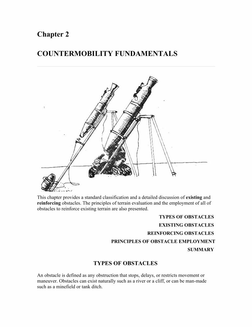
Chapter 2
COUNTERMOBILITY FUNDAMENTALS
This chapter provides a standard classification and a detailed discussion of existing and reinforcing obstacles. The principles of terrain evaluation and the employment of all of obstacles to reinforce existing terrain are also presented.
TYPES OF OBSTACLES EXISTING OBSTACLES
REINFORCING OBSTACLES PRINCIPLES OF OBSTACLE EMPLOYMENT
SUMMARY
TYPES OF OBSTACLES
An obstacle is defined as any obstruction that stops, delays, or restricts movement or maneuver. Obstacles can exist naturally such as a river or a cliff, or can be man-made such as a minefield or tank ditch.

Obstacles are grouped into two general categories, existing and reinforcing, as shown. Existing obstacles are already present on the battlefield and not placed there through military effort. They may be natural such as lakes or mountains, or they can be cultural such as towns or railroad embankments. Reinforcing obstacles are placed on the battlefield through military effort and are designed to strengthen the existing terrain to slow, stop, or canalize the enemy. Reinforcing obstacles are limited only by imagination, time, manpower, or logistic constraints. They include blowing a road crater, constructing a log crib, or installing a minefield. Scatterable mines are reinforcing obstacles emplaced by various delivery systems such as artillery or aircraft.
EXISTING OBSTACLES
The terrain, as it exists, can be a significant asset to the commander who is best able to analyze and use it advantageously. Terrain is not just the field where the battle is fought--it is very much a part of the battle itself. The commander at any level who makes the terrain work in a positive manner against the opponent will most likely win.
There are many things a commander needs to know about the terrain on which US and enemy forces must move, maneuver, and fight. Some of the more obvious items are:

• Roads and bridges. • Built-up areas. • Soil and trafficability. • Slope. • Rivers and streams. • Visibility, climate, weather, and their effects.
The commander's course of action will largely depend on the characteristics of the terrain and intended use of it. The commander's action includes movement, maneuver, and weapons siting to destroy the enemy. All ground movement, friendly or enemy, will be dictated by existing obstacles.
A good analysis of the terrain in the areas of influence and interest should answer the following questions:
• Where are the mobility corridors and avenues of approach? (Where will the enemy come from? Where can I go?)
• How large are the mobility corridors and avenues of approach? (What size enemy or friendly force will they support?)
• What is the trafficability of the avenues of approach? (How fast can the enemy or I travel and with what type vehicles?)
• Where is the key terrain? (What terrain will provide a significant advantage to the one who controls it?)
• What are the fields of fire? (With what weapons and at what ranges can I engage the enemy? Or be engaged?)
• Where are the choke points or extensive obstacle areas? (Where are possible locations to place reinforcing obstacles?)
These questions are not inclusive, but if answered and analyzed, they will provide significant information on how to prepare the battlefield and allocate combat power.
Determining existing obstacle locations is a key element in terrain analysis. The most critical questions are how and where do we get information concerning terrain and existing obstacles. The best source is an on-the-ground reconnaissance accomplished by the units who will fight the battle. However, this is not always possible due to lack of resources or enemy control of the areas about which we need information. Corps and division terrain teams organic to the Theater Army Topographic Battalion collect, analyze, and provide important topographic, hydrologic, and climatic data. Terrain analysts assess observation and fields of fire, cover and concealment, obstacles to movement, key terrain, and avenues of approach. Input to the force engineer and G-3 is especially important for obstacle planning. Engineer terrain analysts work as a team with intelligence analysts to collect raw terrain information and convert it into processed intelligence. Topographic units provide a variety of products including cross-country movement maps, overprinted maps, and various scale tactical maps. Topographic support is invaluable in making a thorough terrain analysis.
Analysis of terrain and existing obstacles should focus on the mobility of tanks. Tactics of enemy combined arms forces are designed around the mobility of tanks. The tank is the primary vehicle we want to restrict, delay, stop, and kill. This antitank orientation of

terrain analysis and obstacle development narrows our focus and makes the task more simple. By focusing on the tank, the terrain analysis team can assist the commander in identifying those existing obstacles that restrict, channelize, delay, or stop the mobility of tanks.
Systematic terrain analysis using all assets available reveals the existing obstacle value of the terrain. Conditions which should be considered when analyzing terrain include drainage features, slope and relief, vegetation, cultural features, and climate. The obstacle value of each condition is evaluated individually in conjunction with trafficability. Then, their combined effects become the obstacle value of the terrain.
DRAINAGE FEATURES
Drainage or surface water features include rivers, streams, canals, lakes, ponds, marshes, swamps, and bogs. Such features are obstacles whenever the water becomes deep or turbulent enough to threaten the safety of soldiers and the operation of vehicles. Drainage features are also obstacles when swamps, marshes, bogs, and the like make soil conditions impossible for cross-country movement.
Large rivers
Large, unfoldable rivers are formidable obstacles because they must be crossed by tactical bridging, swimming, ferrying, or special deep water fording. Ease of crossing these rivers is determined by the width, depth, velocity, turbulence, bank and bottom conditions, rapid tactical bridging available, and existing bridges.
Small rivers, streams, and canals
Minor fordable rivers, streams, and canals are much more numerous than major rivers and their tactical value as obstacles should not be overlooked. These features are variable in effectiveness as obstacles. Careful planning is required to integrate them into the obstacle system. Watercourses frequently constitute elongated obstacles in terrain which may otherwise be excellent for movement. Drainage also influences the orientation of the road net and direction of movement in an area. The destruction of a few selected bridges can force cross-country movement or long detours. During floods, minor rivers and streams can become major obstacles. They can cause conditions which extend the obstacle effect for a considerable period by damaging temporary and expedient bridges, and by deepening the original channel of the river or stream, thus making access or egress difficult or impossible.

Weather effects
Although streams are normally small and slow during periods of low precipitation, and large and rapid during periods of high precipitation, the relationship is not always this simple. Melting snow, for example, may cause high water downstream even in regions where rainfall is low. Continuous below-freezing weather can reduce stream flow even though precipitation may be high.
In winter, ice may be strong enough to support vehicles; then, instead of being obstacles, water bodies may become the preferred avenues for movement. Lightly loaded 2 ½-ton trucks can move on ice 0.3-meter (10 inches) thick. Movement on ice is risky, however, because of weaknesses caused by water flowing from springs and other areas of swiftly moving water.
In arid regions, dry stream channels maybe preferred avenues for movement during periods of little or no flow. However, there may be quicksand or other soft places where vehicles bog down. Also, there is the danger of flash floods.
Fording
Fordability of a stream expresses how easily it may be crossed without the means of bridging or ferrying. Fordability depends on characteristics of both the vehicle and the stream. The significant characteristics of streams are:
• Width of channel. • Depth and velocity of water. • Nature of bottom. • Height, slope, and strength of banks.
FORDING IS POSSIBLE IF DEPTH AND BOTTOM

PERMIT ACCESS AND EGRESS.
These characteristics may vary independently so that fording of even the smallest stream requires selecting a site where favorable conditions coincide. A stream is a minor hindrance when a ford is available and usable with little or no improvement. A stream is a major hindrance if a suitable ford is lacking, or if fording requires considerable preparation of approaches, reinforcement of bottoms, or the use of special equipment on vehicles.
TANKS CAN "SELF-BRIDGE"
UP TO 3M.
A tank can bridge stream channels less than 3 meters wide; however, wheeled vehicles do not have this capability. Once the self-bridging capability of tracked vehicles is exceeded, streams can be crossed only by bridging, ferrying, or fording. Although the width of a stream is significant to bridging, it is relatively insignificant to ferrying (provided it is wide enough) and fording. However, the wider the stream, the greater the hazard involved. For fording, the permissible maximum depth of water for most tanks is between 0.9 to 1.5 meters (3 to 5 feet); and for trucks, about 0.9 meter (3 feet). Vehicles can be equipped with deep water fording devices that will enable them to cross water bodies as deep as 5 to 6 meters (17 to 20 feet). Often, a ford may be negotiated with minor difficulty by the first few vehicles, but the ones remaining will be unable to cross because bottom conditions or approaches have deteriorated with use.
TANKS CAN FORD WATER UP TO
1.5M DEEP AND
1.5M/SECOND VELOCITY.
Stream velocities should be less than 1.5 meters (5 feet) per second for reasonably safe fording. The bottom of stream channels must be firm enough to support vehicles. Bottoms made up of fine-grained material can prevent fording even though the water may be only a few inches deep. Suitable bottoms are restricted to those that are sandy, gravelly, or rocky; but even sandy bottoms may give way under the weight of vehicles, or boulders may prevent vehicular movement. The banks also are important. Hard, vertical banks will be obstacles to tanks, if bank height exceeds 1.5 meters (4 feet), and to trucks, if bank height exceeds 0.3 meter (1 foot). Greater heights can be tolerated if the vehicles can get adequate traction or if assistance such as winching is used. The type of the material composing the banks may be significant. Banks made up of fine-grained soils may fail under repeated traffic. Sandy and gravelly materials usually provide adequate strength and durability.

GROUND RECON IS ALWAYS
BEST.
Adequate information (river studies, special maps) is commonly available on large streams, but generally not for the small streams. Ground reconnaissance is always the best source of information; for many areas, it is the only reliable source. If on-site recon is not possible, then topographic and geographic maps, reports, and aerial photographs are often the only sources of information available. Occasionally, useful data can be found in publications on geology, agriculture, soils, and forestry.
Lakes, ponds, swamps, marshes, and bogs
Large lakes make excellent obstacles. They are usually unfordable, unable to be bridged, and must be bypassed. Smaller lakes and ponds in themselves are not difficult to bypass; however, when connected by streams, they are easily integrated as part of an obstacle system. Because lakes can be crossed by amphibious vehicles or boats, beach and underwater obstacles should be used to discourage enemy ferrying efforts. When lakes are frozen, they may lose their value as obstacles. Swamps, marshes, and bogs severely restrict mobility and force the canalization of vehicular movement onto causeways, greatly increasing vulnerability to air attack, artillery, or direct fire weapons. Historically, swamps have been avoided by attacking armies. Swamps and marshes over 1 meter deep maybe more effective obstacles than rivers, since causeways are usually more difficult to construct than bridges.
Soils
Soil trafficability, especially when considered in conjunction with climatic conditions, is a very important factor in evaluating cross-country movement. Obtaining the necessary information, however, is difficult and time-consuming; and, properly evaluating trafficability strength of soils is a complicated process.
SOIL TRAFFICABILITY IS DIFFICULT TO EVALUATE,
DETERIORATES WITH USE, AND VARIES WITH MOISTURE.
Engineer soils analysis personnel and qualified photo-interpreters are capable of estimating soil. strengths usually required by higher headquarters for planning purposes. The load-bearing capacity of fine-grained soils such as clay, loam, and silt is significantly affected by soil moisture due to the effects of drainage on the water table or weather. Artificially produced high-water tables have made obstacles of meadows or paddy fields which covered large areas. Further, the long-term use of manure for fertilizer adds organic material that reduces soil's trafficability when wet. The combination of soft or slippery soils, and even slight slopes, will stop many vehicles. Tanks have extremely low

ground pressures (8 to 12 pounds per square inch (psi); 0.56 to 0.85 kilograms per square centimeter (kg/cm2)). They have less difficulty with most soils than other vehicles unless unusual wetness or repeated traffic have reduced normal trafficability.
BEARING STRENGTH LESS THAN
8 PSI STOPS TANKS.
Snow
Snow creates a special cross-country movement problem related to soils. Though it is seldom deep enough to be a serious obstacle to tracked vehicles, snow in the spring or fall may occur over saturated, untrafficable ground. It is considerably more of a hindrance and hazard to wheeled vehicles, as most will become immobilized when the depth of the snow reaches one third of the tire's diameter. Snow reduces slope climbing ability, maximum payload capacity, and maneuverability and speed of all vehicle operations.
SLOPE AND RELIEF
Slope is the inclined surface of a hill, mountain, ridge, or any other part of the earth's land surface. It is the inclination not only of major surface relief features (hills and mountains), but also of minor relief features such as ditches, small gullies, mounds, low escarpments, small pinnacles, and sinkholes which generally do not appear on topographic maps. Although some of the minor relief features might be considered a roughness factor rather than slope, they are included in the general slope factor because their obstacle value is due to the steepness of their slopes, banks, or faces. Short, vertical slopes or "steps" higher than 0.3 meter (1 foot), will slow wheeled vehicles, and 1.5 meters (4 feet) will stop tanks.
STEPS OF 1.5M HIGH
WILL STOP TANKS.
In mountainous areas, the steep slopes commonly make cross-country vehicular movement either difficult or impossible. Movement will be channelized by existing terrain. The amount of slope is usually expressed as a percentage, which is the number of meters of elevation difference per 100 meters of horizontal distance. Most military vehicles are able to climb slopes of 60 percent (about 30/35 degrees) under optimum conditions. This limit, however, is too great to negotiate in military operations. In evaluating terrain for cross-country movement, 45 percent (about 27 degrees) is commonly used as the reasonable upper limit for tanks, and 30 percent (about 17 degrees) for trucks. Wet weather, trees, unfavorable soil conditions, snow, boulders, and the employment of reinforcing obstacles may make gentle slopes impassable.

SLOPE OF 45% (27°)
IS PRACTICAL UPPER LIMIT FOR TANKS.
The most reliable information on slopes, particularly short, steep ones, is obtained by on-site reconnaissance. At best, however, slope can be determined on only a small portion of the area by this procedure. Topographic maps are useful but some features may not be shown; for example, small gullies. Terrain teams are the best overall source of up-to-date information to determine slope and other terrain information if an on-site reconnaissance is not possible.
VEGETATION
Vegetation includes not only natural, "wild" vegetation, but also cultivated forests and crops. Forest vegetation is the primary concern in cross-country movement. Trees are the principal obstacles to movement. Although high grass and brush can obstruct vision, they are of relatively little significance in most cases. Nearly all forests, however, have a slowing effect on movement.
The problem is to determine whether a particular forest will slow movement slightly, drastically, or stop it altogether. Temperate zone forests tend to canalize movement since the roads, trails, and firebreaks through them provide the only means for rapid movement. Reinforcing obstacles readily strengthen the defensive value of woods, and are placed both outside and inside the wooded area to delay the advance of the enemy and better utilize supporting fires.
TREES 20 TO 25CM IN DIAMETER,
SPACED NOT MORE THAN 5M APART,
ARE OBSTACLES TO TANKS.
Tree size and density, soil condition, slope, and depth of forests contribute to their obstacle value. Forests with trees 20 to 25 centimeters (8 to 10 inches) in diameter are tank obstacles, and 5-centimeter (2-inch) stands will stop most wheeled vehicles. Fully dependable criteria pertaining to the size of trees, and the significance of species and root systems, have not been determined. Medium tanks, for example, have pushed over single trees as much as 30 centimeters (12 inches) in diameter. Overturning trees within stands can also create complications; for example, if several trees are pushed over, some will interlock with other trees to form a better obstacle to movement. The protruding root system and trunks of overturned trees are obstacles to vehicles. The critical average distance between trees in forests where the trees are too big to be pushed over is about 3 to 5 meters (10 to 16.5 feet), depending upon whether the trees are regularly or irregularly planted. Although this distance may be wide enough for the vehicle to pass

through, in most cases there is no room for turning. Reconnaissance is especially important as a source of vegetation information for two reasons. First, two of the characteristics--the size of trees and the distances between them--are seldom recorded. Second, the size and distances frequently are difficult to determine from aerial photography. Tree blowdown during nuclear attack will present significant mobility problems. Forested areas which have been affected by blast will be impassable to tracked and wheeled vehicles.
CULTURAL FEATURES
Cultural features are constructed works such as stone walls, hedgerows, dikes, canals, drainage ditches, embankments, cuts, fills, and built-up areas, as well as damaged or abandoned vehicles and mobile equipment. Some of these features are considered under the slope factor, some under streams, and some--such as built-up areas--are frequently not evaluated in cross-country movement studies. Cultural features are treated as a separate factor here to insure that they are not overlooked in evaluating terrain for cross-country movement. The obstacle value of a cultural feature depends on its size or extent, location, and construction. Large cities and towns that have many masonry buildings located astride principal communication routes can become obstacles of considerable importance because they can be reduced to rubble and restrict enemy movement. Even if gaps are cleared through the rubble and debris, movement is still canalized. The natural obstacle value of built-up areas can be readily reinforced, and those properly located to control approaches or key terrain can be developed into formidable strongpoints.
CRITICAL FACTORS OF CULTURAL FEATURES ARE
SIZE, LOCATION, AND CONSTRUCTION.
Roads and railroads
Another extremely important cultural feature is the road and railroad net. It will have a fundamental influence on an attacker's choice of approaches, because--
• The anticipated rates of advance will force the attacker (except the lead elements of his main body) to move on roads, unless combat or imminent combat forces him to deploy into tactical formations.
• The road net is critical to the movement of the attacker's following echelons. • The attacker must have a well-developed road and/or railroad net for his logistical
support.
Every break in this road and railroad net creates an obstacle to an attacker's rapid tactical movement, the movement of his following echelons, and his logistics. If the break is in his division rear or farther back, its effect is interdiction. Corps and division obstacle plans, as well as denial plans, must consider this effect. Further, a highly developed road and/or railroad network with its numerous cuts, fills, and embankments creates obstacles

to transverse movement which are comparable in extent to the drainage network. The German autobahn system is an excellent example.
Minor cultural features
Minor cultural features also can act as deterrents or obstacles to movement. A stone wall or hedgerow is a serious obstacle, unless the sheer weight of a vehicle can push through it. Accordingly, the height and thickness of such walls or hedgerows, as well as the height of embankments and the slope on either side, determine obstacle value. Embankments more than 3 meters (10 feet) high with side slopes greater than 45 percent can be serious obstacles. Cuts have similar significance. Large gravel pits, quarries, or areas where strip mining has taken place may present obstacles or traps for vehicles. These, too, must be evaluated, particularly with respect to slope and soil characteristics.
Streams or drainage ditches that appear insignificant on a 1:50,000 scale tactical map may be of significant value in canalizing or slowing enemy movement. They are easily reinforced and can be integrated into the overall obstacle plan with only small amounts of effort expended. Although most of the minor cultural features can be interpreted from air photos, and many may be shown on topographic maps, the features' dimensions, which directly affect cross-country trafficability, are difficult or impossible to determine from photos and maps. Thus, cultural feature information that may be most relevant to cross-country movement is frequently available only through over-the-ground reconnaissance or from terrain teams.
CLIMATE
Climate and weather both significantly affect cross-country movement, although their effects are usually indirect, and their influence is variable in duration and difficult to predict. Climatic influences are usually reflected in the nature of the terrain and obstacles. To a large extent, climate controls soil moisture, and thus soil strengths. It also determines basic river and stream characteristics. Some easily overlooked direct effects of climate are important. Fog and haze, common in some areas, significantly affect weapons employment and can retard or even prevent movement. Dust storms and snowstorms have the same effect.
FOG, HAZE, AND BLOWING SNOW CAN BE EFFECTIVE OBSTACLES.
Seasonal weather patterns are important. An attacker anticipating a quick victory may choose to strike at any time of the year. Existing obstacles should be evaluated on the basis of the seasonal weather conditions to determine their obstacle value.
The ability to evaluate terrain and properly assess its obstacle value provides a significant advantage to the commander who does it well. A good analysis enables the commander to determine avenues of approach, key terrain, and best areas for weapons employment. It also provides the commander a beginning for the obstacle plan. Full use of existing

obstacles will help in conserving precious manpower and logistical effort necessary to emplace reinforcing obstacles.
COMBINED EFFECTS
The preceding paragraphs have discussed the individual principal terrain factors affecting existing obstacles. Usually, their combined effect is far more important and considerably more difficult to define. Slopes combined with vegetation and/or soil conditions limit vehicular mobility far more than any one of these factors alone. The obstacle effect becomes apparent long before any of the individual factors reach their critical values. The tank's weight magnifies the effect of even a slight rise by reducing its speed. For example, even though a tank can push over a tree 25 centimeters (10 inches) in diameter on level ground, the same tree will stop the tank on a slight uphill slope. Further, the combined effect of several less-than-critical features or factors can stop the enemy's armored vehicles. Closely spaced trees much smaller than 25 centimeters (10 inches) in diameter will stop a tank even on level ground. Even more important is recognizing that the critical values discussed in the preceding paragraphs are the limits for halting movement. Lower values of slope or smaller trees, steps, ditches, and so on, will severely slow the enemy's movement. A high frequency or density of features that are less than critical can severely reduce, although not stop, the enemy's speed. For example, a tank may eventually force its way through one of West Germany's densely-cultivated forests that has not reached full growth, but only by repeated lunges at a very slow effective rate of movement. To consider another example, every tanker knows how effectively a number of terraces or ditches, each individually crossed, can interfere with movement. It is not always necessary to completely stop the enemy's armored vehicles. Frequently, it is more desirable to slow but not stop him. If the goal is to lead enemy formations along a certain passage or in a particular direction--into a desired engagement area for example--or to lure enemy tanks to expose their less-heavily armored flanks, then it may be preferable not to stop him.
LESS-THAN-CRITICAL TERRAIN FEATURES CAN
SLOW BUT NOT STOP ENEMY TANKS.
Other effects, although not necessarily obstacle effects, also must be considered. The effect of slopes, in conjunction with limited depression and elevation of the tank's main gun, is important in siting both antitank weapons and obstacles. A steep cross-slope also makes it more difficult for the gunner to rapidly deliver accurate fire, thus giving the defender a relative advantage.
Finally, terrain factors are evaluated in light of the movement of a combined arms formation, and not of one tank. Threat forces attack in relatively fixed formations. Natural or cultural obstacles that stop or slow a part of the formation will thus affect the movement of the entire formation, either to slow it or change its direction. This effect emphasizes the slowing ability of less-than-critical terrain factors or features. It also provides the basis for siting many of the defender's reinforcing obstacles. The effect of

combinations and variations of natural or cultural obstacles makes their evaluation a complex skill, one that requires experience and practice to develop its full potential.
REINFORCING OBSTACLES
The previous section developed the concept of existing obstacles as a part of the terrain, and discussed their characteristics, identification, and analysis. This section considers the use and types of reinforcing obstacles that the commander can use to knit together, strengthen, and extend existing obstacles in support of his tactical plan. Reinforcing obstacles are those obstacles specifically constructed, emplaced, or detonated to extend or improve the effectivess of existing obstacles. They are placed for the purpose of anticipated military action or action already in progress.
REINFORCING OBSTACLES ARE CREATED TO SERVE
A PLANNED OR

ON-GOING MILITARY ACTION.
Many existing obstacles tend to be lengthy (rivers, canals) or broad in extent (forests, swamps). They can often more accurately be described as obstacle areas rather than a single obstacle. Existing obstacles are highly variable in effectiveness from place to place and have frequent gaps or openings between, and lanes (roads, bridges) through or over them.
REINFORCING OBSTACLES TIE TOGETHER TO
STRENGTHEN AND EXTEND EXISTING OBSTACLES.
After thoroughly examining existing obstacles and obstacle areas, and then determining their relative stopping power, the commander has a much better feel for the use of reinforcing obstacles. Given the general tactical plan, time, logistic support, and manpower, the commander is able to add reinforcing obstacles to strengthen the terrain. Reinforcing obstacles normally are used to close gaps and block or close the lanes in the existing obstacle areas, or to enhance the obstacle value of the terrain. In some cases, they are used to extend natural obstacles or create obstacles or obstacle systems in open country.
The nature and extent of reinforcing obstacles is limited only by the imagination of the commanders or engineers who design them and the soldiers who emplace them. They are also limited by the logistic effort required. Reinforcing obstacles can range from massive systems such as the beach defenses constructed on the French coastline during World War II, or the extensive antitank obstacles in the 1973 Middle East War, to a road crater emplaced by an engineer squad. Reinforcing obstacles can vary greatly in type, method of emplacement, and logistic and manpower requirements. Reinforcing obstacles can be broadly categorized by the following types:
• Demolition. • Constructed. • Land mines. • Contamination. • Expedient.
These categories are not mutually exclusive--some obstacles appear in more than one category and some (such as mines) are commonly used to strengthen others.
DEMOLITION
Demolition obstacles are created by the detonation of explosives, including nuclear explosives. Demolitions are commonly used to create reinforcing obstacles. There are two types of demolition obstacles, preliminary and reserved. Preliminary demolition obstacles are not absolutely critical to the tactical commander's plan, and do not require a formal written demolition order. They can be detonated as soon as they are prepared or as

the tactical situation dictates. Reserved demolition obstacles are critical to the tactical commander's plan, and require a formal written demolition order. They are detonated according to the instructions in the order. Chapter 4 provides complete details on re served demolition obstacles. Some typical uses of demolition obstacles are:
• Blowing craters in roads, airfield runways, taxiways or parking areas, and railroads.
• Destroying bridges or tunnels. • Demolishing buildings to create rubble. • Flooding areas by destruction of dams or locks. • Creating abatis by tree blowdown. • Blowing ditches using solid or liquid explosive. • Detonating prechambered roads and bridges.
CONSTRUCTED
Constructed obstacles are those reinforcing obstacles that are built by soldiers and machinery, generally without the use of explosives. Typical examples are:
• Wire. • Tank ditches. • Log cribs. • Steel "H" beam post obstacles. • Falling or tumble blocks. • Dragon's teeth, hedgehogs, and tetrahedrons. • Nonexplosive abatis.
Constructed obstacles generally require extensive amounts of one or all of the following:
• Manpower. • Equipment. • Material. • Time.
Soldiers and construction equipment can be exposed to all types of enemy fire when emplacing constructed obstacles. Constructed obstacles should be emplaced prior to the start of the battle, or a terrain feature away from direct engagement areas, so that observed fire cannot disrupt the emplacement process.
LAND MINES
Reinforcing obstacles other than minefield are primarily designed to enhance the fires and kill ratio of antitank weapons. Mines and minefield perform this function as well as killing or destroying enemy vehicles and personnel.
Mine warfare is undergoing a tremendous evolutionary process. Significant improvements have been made in mines and mine delivery systems. We have the capability to quickly emplace mines anywhere on the battlefield using various delivery

systems. Mines have changed to the point where we now have to discuss them in two separate categories, conventional and scatterable mines. This categorization is required due to the different capabilities, employment techniques, and delivery means of each. Both categories of mines have a distinct place on the battlefield and complement each other.
Conventional mines are those mines not designed to self-destruct. Conventional mines are designed to be directly emplaced by hand or by mechanical mine planting equipment. They can be buried or surface-laid. Conventional mines can be emplaced in a classical pattern or without regard to pattern as the tactical situation dictates.
Scatterable mines are those mines which are designed to self-destruct after a set period of time. With the exception of the Wide Angle Side Penetrating Mining System (WASPMS) which is directly emplaced, scatterable mines are remotely delivered by ground systems, artillery, helicopters, and high-performance aircraft. The term "scatterable" refers to selfdestructing mines. It should not be used to describe conventional mines which have been laid without regard to pattern.
Scatterable mines have added a new dimension to mine warfare and the battlefield. The traditional concept of large linear minefield across contested areas between two forces is no longer viable, except possibly in desert warfare. Future battlefields will contain many smaller mined areas placed in response to enemy dispositions and movement. Scatterable mines will be employed against enemy units anywhere on the battlefield. Scatterable mines can be emplaced by a variety of delivery systems ranging from mechanical and explosive ground systems to artillery, helicopters, and high-performance aircraft. Scatterable mines significantly reduce manpower requirements associated with mine warfare. Scatterable mines are also smaller, lighter, and more lethal. They offer a reduction in logistical requirements due to reduced bulk and weight.
NOTE: The reader should beware of the terms "scatterable" and "Family of Scatterable Mines (FASCAM)" when referring to specific systems and their employment. Those generic terms are only applicable in the most general sense when discussing doctrine. Whenever possible, refer to the specific delivery system and the characteristics of that system, rather than the generic term.


Mines are used extensively where the existing obstacle structure is weak or nonexistent. They should also be used with other reinforcing obstacles, such as tank ditches, to make breaching and clearing more costly and time-consuming to the enemy.
Since all scatterable minefield systems provide great flexibility to maneuver commanders, there will be extensive demands for them. Commanders and engineers should plan and carefully assign priorities. Available systems must be used for the most critical needs. Employment must be closely coordinated with obstacle plans, fires, and the scheme of maneuver. Coordination with fire support planners, aviation staff officers,

and air liaison officers is essential to insure prior planning to execute minefield emplacement missions on short notice. Planning and employment of scatterable mines, as well as conventional mines, are discussed in depth in chapter 5.
CONTAMINATION
Contamination can be either nuclear or chemical in nature. Both types are difficult to predict and control because they depend on winds for placement, and are subject to weather and other environmental factors. The United States has renounced the first use of chemical weapons. Further, the most predictable source of nuclear contamination, Atomic Demolition Munitions (ADM), is subject to the same restrictions as all nuclear weapons and may not be available for use when needed. If an ADM is used for cratering, there will be both close-in radiation and fallout, each effectively contaminating an area of reasonably predictable extent. Threat doctrine considers the use of both nuclear and chemical weapons, and threat forces train for operations in contaminated areas. The presence of contamination and its effects on the battlefield must be anticipated.
EXPEDIENT
The potential of expedient obstacles is almost unlimited. They place a great premium on imagination and ingenuity in the use of available materials and other resources, thus avoiding the logistic burden associated with all other types of obstacles. All sorts of nonstandard log obstacles can be built. Their complexity depends upon the time and personnel available. Junked or destroyed cars and trucks or other debris can be spread to block an open area or, if the region is rocky, earthmoving equipment can be used to distribute boulders to block tanks. Selected trees can be pushed over to make an abatis or to strengthen a wooded area where tree spacing might otherwise allow armored vehicles to pass. Short ditches can be cut in lieu of craters. Material can be pushed up to form a road block. Equipment can steepen or deepen stream banks, gullies, or other breaks in the terrain to make expedient tank ditches. Trees can be cut or broken with a variety of vehicles or pieces of equipment. They can also be pushed or pulled down by winches to form expedient abatis or strengthen wooded areas. The M9 Armored Combat Earthmover (ACE), dozers, loaders, and many other pieces of equipment can also be used.
The wreckage of destroyed towns, cities, or industrial areas offers a source of materials to be used in making expedient obstacles. If permitted, limited controlled flooding can be used, not only to inundate areas, but also to create soft or slippery areas where soil conditions would make this possible. Timber bridges can be burned, and controlled fires can be used to create obstacles in other ways. For example, igniting the brush in a brush-filled ditch, at the proper time, can make an effective obstacle. If available, ice and snow can be exploited to create effective obstacles.
By their nature, expedient obstacles substitute locally available materials and soldier labor for a logistical requirement. All that is needed is the imagination to recognize the potential of available materials.

PRINCIPLES OF OBSTACLE EMPLOYMENT
AirLand Battle doctrine gives the commander fighting the battle a complete range of defensive and offensive options. A static type defense can be used to focus upon terrain retention using firepower from fixed positions to deny terrain. The commander can also defend using a dynamic defense that focuses upon maneuver to destroy enemy forces rather than retain specific terrain.
The static and dynamic defensive frameworks are the extremes of the spectrum. Typically, the commander may choose to combine both the static and dynamic forms in organizing the defense based upon the factors of mission, enemy, terrain and weather, time, and troops (METT-T).
Whatever the concept, organizing the defense must be carefully matched to the terrain. The engineer is the principal element in reinforcing the terrain to best complement the maneuver commander's plan. The engineer and the maneuver commander must coordinate throughout the planning and battlefield preparation sequence to insure unity of effort and maximum effectiveness of obstacle employment.
Terrain reinforcement techniques must be employed along the depth of the enemy's formation and avenues of approach where existing terrain places him at the greatest disadvantage. Use of reinforcing obstacles is the principal method of terrain reinforcement. Reinforcing obstacles must be used in conjunction with the existing obstacles and the commander's plan. Reinforcing obstacles have three primary purposes:
1 Enhance the effectiveness of friendly antitank fires.
2 Delay the enemy's advance, upset his timing, disrupt and channelize his formations, and delay or destroy follow-on echelons.

3 Enhance friendly economy of force measures.
Obstacles must be covered by fire if at all possible. They should be located within the effective range of friendly direct fire antitank weapons. Their locations must be carefully coordinated with the location of battle positions and direct and indirect weapons. We want to engage the enemy at the maximum effective range of our antitank weapons, and force him to breach and fight his way through a series of obstacles while under intense fire. Each obstacle delays some part of the enemy's leading elements.
AN OBSTACLE CAN SIGNIFICANTLY ENHANCE
ANTITANK FIRES.
The coordinated use of obstacles can delay and disrupt enemy formations, and also force them into the primary fields of fire of our tanks and other antitank weapon systems, or prevent escape from such an engagement area. The enemy is forced to move on the battlefield in conformance with the friendly commander's plan.
COORDINATED OBSTACLES DELAY, DIVERT, CANALIZE,
AND DESTROY THE ENGAGED ENEMY AND
FOLLOW-ON ECHELONS.
The skillful use of obstacles to channelize the enemy is a vital factor. Once the enemy force maneuvers into the engagement area, it is held there by other groups of obstacles, and still others may be used to close the trap behind it. (Scatterable mines are ideal for the latter purpose.) Other obstacles are used to separate the enemy's leading elements from reserves or following echelons, thus precluding reinforcement.
Mutually supporting obstacles serve other important purposes. They can be used in the economy of force role to strengthen a naturally strong existing obstacle area so that it need only be lightly defended, thus freeing forces to be concentrated elsewhere. Similarity, obstacles can be used in conjunction with mobile forces to protect flanks and other lightly defended areas. This is a particularly important role in view of the threat doctrine of penetration and envelopment, and the overall dispersion of forces on the battlefield.
Regardless of the type defense employed by the tactical commander, there are five basic employment principles for reinforcing obstacles:
1 Reinforcing obstacles support the maneuver commander's plan.
2 Reinforcing obstacles are integrated with observed fires.
3 Reinforcing obstacles are integrated with existing obstacles and with other reinforcing obstacles.
4 Reinforcing obstacles are employed in depth.
5 Reinforcing obstacles are employed for surprise.

1 Reinforcing obstacles support the maneuver commander's plan. Reinforcing obstacles must be planned and emplaced to support the tactical plan. Obstacles other than mines emplaced outside the range of friendly weapons are of little use. Reinforcing obstacles that do not accomplish one or more of the basic purposes of reinforcing obstacles are also of little value. Engineers must be completely familiar with the tactical plan, the existing terrain, and the maneuver commander's intentions. Only then can full advantage of the multiplier value of integrating obstacles and fires be realized.
2 Reinforcing obstacles are integrated with observed fires. Obstacles are used to develop engagement areas in which enemy maneuver is restricted and slowed, thereby increasing the hit probability of friendly direct and indirect fires. The tactical commander and the engineer site the weapons and obstacles which offer the best relative advantage, and consider terrain configuration and the effective weapons range. Special attention must be given to locating obstacles to complement the fires of Dragon, tanks, and tube-launched, optically tracked, wire-guided missiles (TOWs). Since TOWs have a greater maximum effective range than Threat tanks, it is to our distinct advantage to site part of the tactical obstacle system to capitalize on that difference. Generally, the greatest relative advantage accrues when the obstacle is at the maximum range possible and consistent with visibility conditions and the tactical plan. Observed indirect fires are also used in conjunction with obstacles against enemy vehicles and infantry out in the open. Observation and adjustment of fires are essential if the full advantage is to be developed. At the same time, fires serve to protect the obstacle by making it costly to breach or bypass. With rare exceptions, obstacles that are not covered by fire are little more than a nuisance to the enemy's leading elements.
Keep in mind, however, that the principal purpose of integrating obstacle locations with fire is to enhance the effectiveness of those fires--a significant combat multiplier effect of obstacle use.
3 Reinforcing obstacles are integrated with existing obstacles and with other reinforcing obstacles. Reinforcing obstacles are sited to take the maximum advantage of existing obstacles. They are placed where they can close the gaps or openings between existing obstacles and/or close any passages through them. The road network must be destroyed and the inherent natural pattern of cross-country movement should be disrupted. The first obstacles planned are bridge demolitions, road craters, abatis, and point or small minefield that tie together the existing obstacle areas and close the passages through them. Other reinforcing obstacles are then located to strengthen and extend the existing obstacle areas and block major corridors. Taking advantage of the existing obstacles reduces the resources required to quickly obtain an effective obstacle system. Effective reinforcement of existing obstacles also enhances economy of force operations by permitting friendly forces to concentrate on more trafficable terrain approaches.

Individual obstacles must be sited and designed to tie in with existing obstacles or with each other. An obstacle that can be bypassed immediately is worthless. Each individual obstacle must be carefully designed for the exact location it will occupy, and must overlap on each side with the existing obstacle it will complete. The critical design width of an obstacle is the distance from an existing obstacle to another existing obstacle (or to another reinforcing obstacle), and not the width of a road or highway through the existing

obstacle.
Another major design consideration is that the reinforcing obstacle does not need to be stronger than the integrated existing obstacle. The obstacle should be no more difficult to breach than it is to get around. If the enemy could force his way through the existing obstacle in the immediate vicinity in 10 minutes, it would be wasteful to construct a reinforcing obstacle requiring 40 minutes to breach. The effort and resources used to obtain the last 30 minutes of breaching time are desperately needed elsewhere. Although the delay or breaching time associated with a particular obstacle may be difficult to determine, this principle must nevertheless be kept in mind to obtain the most use of available resources.
Reinforcing obstacles are integrated with each other to assure that probable bypass routes are closed. For example, destruction of a major highway through a wooded area is largely ineffective if any nearby road or opening that offers a ready bypass route is left open. (Such destruction could be highly effective, however, if friendly forces were seeking to divert the enemy along that bypass route.) Reinforcing obstacles can also be used to close gaps and lanes in other reinforcing obstacles. For example, a crater can be used to close a road left open through a minefield when all friendly troops have cleared.
4 Reinforcing obstacles are employed in depth. A series of simple obstacles arranged one behind the other along a probable axis of enemy advance is far more effective than one large, elaborate obstacle. Restricting the design of obstacles to correspond with the strength of the existing obstacle (as previously discussed) helps to conserve effort and direct it toward executing obstacles in depth. Obstacles must not be located too close together so only a single enemy response is required. They must be far enough apart that

each will require a new deployment of the enemy's counterobstacle forces and/or equipment. The distance between obstacles will depend on the terrain and the obstacle effort available. Proper use of obstacles in depth wears the enemy down and significantly increases the overall delay. At each new obstacle, he incurs losses and is forced to stop and react. This wearing down effect is psychologically significant. The desired effect is to degrade the enemy soldier's will and induce a feeling of hopelessness. This can be done by convincing him that, beyond each new obstacle (with its attendant loss of personnel and equipment), there awaits another obstacle with a similar cost; and, beyond that one, yet another, and so on. Another reason for using a greater number of less elaborate obstacles is that each one forces the enemy to expose his limited counterobstacle equipment and troops to loss. When the counterobstacle resources initially allotted to the leading elements have been destroyed, the enemy's movement will be severely slowed until new counterobstacle units can be brought forward.
5 Reinforcing obstacles are employed for surprise. Using obstacles so as to obtain surprise is one means available to the commander to retain a degree of initiative even when defending. Scatterable mines permit rapid mining anywhere in the battle area, confronting the attacker with a completely new situation almost instantly. The self-destruct feature of the scatterable mine also provides surprise--a friendly counterattack may be launched through an area that was mined prior to the attack but where the mines have just self-destructed.
More conventional ways to obtain surprise are also available and should be used. They include the sudden detonation of concealed obstacles in front of the attacking enemy or within his formations. Conventional ways also include the use of phony obstacles to mislead the enemy as to the pattern and extent of the friendly obstacle system. An obvious pattern of obstacles would divulge locations of units and weapons. Friendly forces must avoid readily discernible, repetitive patterns. By varying the type, design, and location, the enemy's understanding and breaching of our obstacle system is made more difficult. Extensive use of obstacles can make a major contribution to this effort.
Reinforcing obstacles which complement the existing obstacle value of the terrain, and are designed and emplaced to support the maneuver plan, are an effective "combat multiplier." Tactical commanders and engineers must exploit the full value of obstacles.
SUMMARY
Obstacles are classified as either existing or reinforcing. Existing obstacles are those natural and cultural restrictions to movement that are a part of the terrain when battle planning begins. The ability to recognize and evaluate the obstacle potential of the terrain is critical to planning the battle. Reinforcing obstacles are constructed, emplaced, or detonated to knit together, strengthen, and extend exisiting obstacles.
Reinforcing obstacles must be integrated with friendly observed fires, the friendly commander's maneuver plan for both the enemy and friendly forces, and existing and reinforcing obstacles. Reinforcing obstacles must also be arrayed in depth and employed for surprise.

Mines are generally the most effective type of obstacle because they also inflict losses on the enemy, and their use is highly flexible. The Family of Scatterable Mines (FASCAM) vastly increases this flexibility, making the creation of rapid minefield possible.
Obstacles are also used to delay and disrupt an attacking force, upset the enemy's timing and plans, and divert him into engagement areas and be destroyed. Obstacles can delay or destroy follow-on echelons.
Obstacles can significantly enhance the effectiveness of our fires and thus our ability to win the battle.
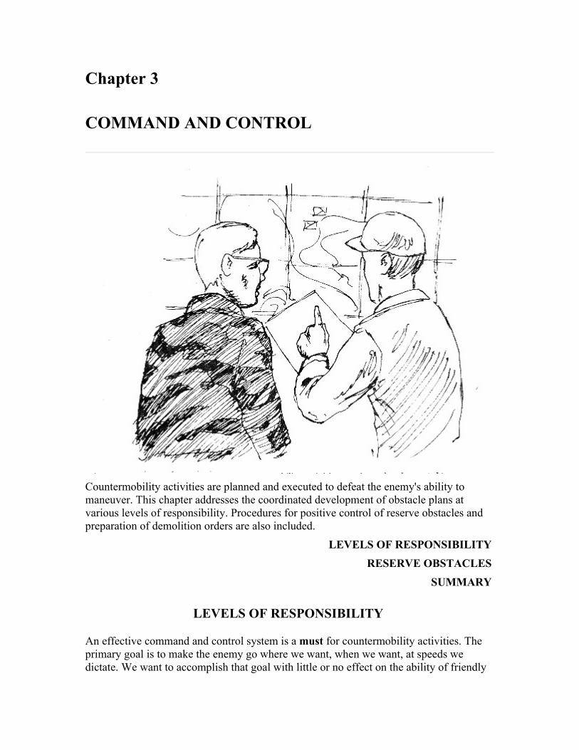
Chapter 3
COMMAND AND CONTROL
Countermobility activities are planned and executed to defeat the enemy's ability to maneuver. This chapter addresses the coordinated development of obstacle plans at various levels of responsibility. Procedures for positive control of reserve obstacles and preparation of demolition orders are also included.
LEVELS OF RESPONSIBILITY RESERVE OBSTACLES
SUMMARY
LEVELS OF RESPONSIBILITY
An effective command and control system is a must for countermobility activities. The primary goal is to make the enemy go where we want, when we want, at speeds we dictate. We want to accomplish that goal with little or no effect on the ability of friendly

forces to move and maneuver. To do so requires a command and control system that emphasizes long-range planning, centralized control, and decentralized execution. Centralized control is necessary in the planning of countermobility activities to insure that the obstacle plan is integrated with and supports the overall tactical plan. Senior command levels must dictate obstacle zones, obstacle-free areas, and reserve obstacles in the planning process. The specific type and placement of those ground obstacles are best accomplished by the level that can actually conduct a ground reconnaissance.
CORPS OBSTACLE PLAN
Centralized control of countermobility activities normally begins at the corps level with the corps obstacle plan. The corps obstacle plan is general in nature and concerned with the employment of obstacles as a part of a specific tactical operation. The obstacle plan supports the corps commander's concept of the operation and integrates the terrain aspects of the operation with the tactical plan. Through the allocation of engineer support and logistics, the corps commander shapes the countermobility efforts of the division by weighting those areas viewed as most critical. The corps obstacle plan provides a framework for the division plans. The corps obstacle plan can and will normally include the following items:
• Assignment of areas of responsibility. • Designation of any specific obstacles vital to the corps as a whole. • Completion times for all or any portion of the obstacle plan when deemed
necessary; however, completion times can be specified later. • Gaps, lanes, and important routes to be kept open and areas important to the
commander for tactical and combat service support operations, as well as for future operations. Gaps and lanes are specifically designated at the lowest level practicable in consonance with the mission of the command.
• Allocation of engineer support, materials, transportation, and equipment. • Reporting instructions to insure all headquarters in the chain of command keep
abreast of the obstacle situation and plan their operation accordingly. As a minimum, reports to division level must include target or obstacle identification, location, and status.
• Coordination required between adjacent units to insure critical points (such as common boundaries) are effectively covered, gaps and lanes are properly located, sufficient in number, and not closed for passage before the time required.
• Procedures for employment of scatterable mines to include provisions for air and artillery delivery, if not specified by standing operating procedure (SOP).
• Limitations or restrictions on the employment of certain reinforcing obstacles such as minefield and booby traps, chemical contamination, and ADM. To guard against premature execution, restrictions may be placed on the employment of reinforcing obstacles. The corps may accomplish this by requiring subordinate units to request approval for the closure of specific gaps and lanes. The corps may also retain approval authority for clearance or release of control over specific routes prior to the destruction of bridges and other transportation facilities. The corps commander maintains surveillance over tactical operations and removes any

restrictions imposed on the execution of obstacles as early as possible to give subordinate units maximum freedom in operations.
• Limitations or restrictions on the emplacement of obstacles in a specific area. Corps may designate areas to remain obstacle-free, assuring the corps commander freedom of maneuver for counterattacks and reinforcing movements.
• Limitations on, and conditions for, the destruction of facilities of strategic importance such as locks, dams, major bridges, and tunnels.
• Instructions regarding the submission of detailed obstacle plans for approval.
CORPS OBSTACLE PLAN
PREPARED BY: Corps HQ
SCOPE: Comprehensive, coordinated plan which includes:
1 Responsibilities
2 General locations of unspecified obstacles
3 Specific obstacles
4 Special instructions, limitations, coordination, completion times
BASED ON: Guidance from higher HQ, tactical plan, maps, aerialphotos, terrain analysis, general recon of the area
The corps obstacle plan is a command and control means for the corps commander to communicate the countermobility concept to subordinates. Corps obstacle plans must be provided to the Army Battlefield Coordination Element (BCE) which is the land forces coordinating agency with the Air Force Tactical Air Control Center (TACC). This coordinating and sharing of information is accomplished for several reasons:
• Assist USAF targeting efforts. Knowing the location of land force emplaced obstacles will assist the Air Force in attacking concentrated enemy elements created by obstacle employment.
• Prevent duplication of effort by air and land forces. • Assist ground movement by USAF elements such as radar and logistic elements.
As the corps obstacle plan is modified or executed, continuous information will be provided by the corps to the BCE which will have the information available for TACC planning. Known locations of enemy obstacles will be included.
DIVISION OBSTACLE PLAN
The corps plan/order is received at division and analyzed for specified and implied tasks. Once this is accomplished, the division obstacle plan is developed in two stages, initial

and final.
Initial plan
An initial plan, based on the corps obstacle plan, division tactical plan, fire plans, maps, terrain analysis, and reconnaissance, is disseminated to the brigades and other subordinate units as quickly as possible to allow time for obstacle selection on the ground. This must be done in conjunction with selecting fighting positions and locating weapons systems. The initial plan will include an overlay showing, as a minimum, targets directed by corps or higher headquarters and obstacles of such importance as to be specified by division. The plan may also specify obstacle zones to be developed by designated unit(s). In addition, the plan will assign responsibilities and, where necessary, priorities; allocate obstacle materials to include scatterable mines; and generally include as much of the information described for the corps plan in whatever available detail as appropriate.
DIVISION OBSTACLE PLAN
PREPARED BY: Division HQ
INITIAL SCOPE:
1 Concept and detailed guidance
2 Specific obstacles directed by corps or division, responsibilities,and obstacle priorities
BASED ON: Corps obstacle plan, division tactical plan, fire plans,maps, aerial photos, and general recon of the sector
FINAL SCOPE: Completes the cycle. Specifically identifies eachobstacle in the division obstacle system to include:
1 Target type
2 Target number
3 Coordinates
4 Priority
5 Completion date/time

6 Responsible unit
7 Special instructions (execution times/authority)
UPDATE BASED ON: Brigade plans and input from other units
following ground recon and obstacle selection
Final plan
After the brigades develop their obstacle plans in detail, and other units develop assigned portions of the division obstacle plan by selecting individual obstacles, these subordinate plans are then incorporated by division with the initial plan to produce the final plan. The plan will normally be issued as an annex to the division operations order.
When time is extremely limited, the division plan may never develop beyond the initial concept plan. Conversely, when adequate time is available, the division plan will be submitted to corps and may be incorporated into a republished corps obstacle plan. The complete division obstacle plan should hot be carried forward of division headquarters because of the danger of compromise. Division provides each brigade with extracts of the detailed plan to include pertinent portions of the plans of adjacent brigades.
BRIGADE OBSTACLE PLAN
Brigades and comparable units develop a detailed obstacle plan, within the guidance provided by division, based on their tactical plans and detailed terrain reconnaissance. To be effective, obstacle plans must be integrated at maneuver unit level. This process is described in chapter 4. If combat is imminent, preparation of obstacles begins immediately without waiting for approval of the obstacle plan. Obstacle construction and obstacle plan development continue con-currently. Final brigade obstacle plans include:
• Location and type of each obstacle, including those specified by higher headquarters.
• A timetable and priority of construction for obstacles. • Specific orders stating under what conditions and by whose authority reserve
obstacles are to be executed. • Routes to be kept open in accordance with the tactical and logistical plan,
including those specified by higher headquarters. • Exact location and extent of gaps and lanes, including those specified by higher
headquarters.
RESERVE OBSTACLES
Reserve obstacles (non-nuclear) are those obstacles or demolition targets the commander deems critical to the tactical plan. The authority to execute the obstacle is reserved by the
authorizing commander through a formal order known as a demolition order. Reserve obstacles must be carefully selected. Their proper execution requires a manpower allocation that could be used elsewhere if it is not required to guard and execute a reserve obstacle. If not executed timely and properly, reserve obstacles could be catastrophic to the tactical plan or operation. An excellent example of a failure to execute a reserve obstacle is the Remagen bridge in World War II.
REMAGEN BRIDGE
As Allied Forces advanced to the vicinity of the Rhine River in early March 1945, the Germans made preparations to demolish all bridges across that wide river. The German high command planned to use the Rhine as a moat to afford their beleaguered forces a badly needed rest. Each time the Allies attempted to capture a Rhine River bridge, the Germans methodically and efficiently destroyed it. However, at one bridge--the Remagen railway bridge--a confused situation was ripe for disaster.
The German bridge garrison at Remagen consisted of an understrength infantry company, a handful of engineers, and a smattering of Volksturm or Home Guard units. These elements were under the command of Captain Bratge, the infantry company commander. The engineers were commanded by Captain Friesenhan. Neither Captain Bratge nor Captain Friesenhan had specific instructions concerning the demolition of the bridge. The engineer commander had standing orders to execute the obstacle only upon the written order of the tactical commander (Captain Bratge). At dawn on 7 March 1946, a steady stream of disorganized German units and stragglers were fleeing l cross the bridge. These soldiers brought stories of large American forces approaching rapidly from the west. Alarmed, Captain Bratge attempted to contact higher headquarters for instructions. He was only able to reach a duty officer at Army Group B who assured him that headquarters was not concerned about the situation at Remagen. At 1115 hours, Captain Bratge was approached by a German officer who identified himself as Major Scheller. Major Scheller stated that he had been sent by the commander of LXVII Corps to assume command at Remagen. The Corps was holding a bridge-head on the west bank of the Rhine, but the perimeter was rapidly being forced toward Remagen. Once Captain Bratge had assured himself of Major Scheller's identity, he gladly relinquished command. Unfortunately, the vehicle containing Major Scheller's radio had become lost enroute to Remagen; thus, he had no means of communication with higher headquarters and no specific instructions.
Soon after 1300 hours on 7 March 1945, Major Scheller received reports that American forces had reached the bluffs over-looking the Remagen bridge. Major Scheller was reluctant to destroy the bridge because a German artillery captain insisted his battalion and its guns were going to cross the bridge shortly. Captain Friesenhan crossed to the west end of the bridge. He planned to execute a crater

which had been emplaced some months before to prevent tanks from rapidly reaching the bridge. Around 1600 hours. a company of American infantry and tanks appeared at the approaches to the bridge. On his own authority, Captain Friesenhan fired the crater, then raced across the bridge to find Captain Bratge and Major Scheller to get the order to blow the bridge. Enroute, he was knocked senseless by a concussion from a tank shell. Fifteen minutes passed before he regained consciousness, continued across the bridge, and obtained approval to fire the demolition. Initially, Captain Friesenhan insisted on written orders, but then relented in the interest of time.
Captain Friesenhan turned the key to electrically fire the charge, but nothing happened. He tried again and again with no results. He realized that the firing circuit was broken. By this time, American machine gun fire and tank fire were sweeping the bridge. Repairs to the circuit were out of the question. A sergeant volunteered to go out on the bridge and fire an emergency charge nonelectrically. The sergeant dashed out on the bridge, and returned on the run minutes later. The charges exploded, but when the dust settled, the bridge still stood. American First Lieutenant Karl H. Timmerman, commander of A Company, 27th Armored Infantry Battalion, and his soldiers rushed across the bridge. They established the beginnings of a bridgehead which would enable US forces to transport 8,000 soldiers, including one tank battalion, across the Rhine in the next 24 hours. Captain Friesenhan and Captain Bratge were captured. Major Scheller and three other officers were tried by a German military tribunal, and were executed by a firing squad.
Some obviously glaring errors which proved extremely costly to the German Army included:
• Insufficient guard force. • Inadequate communication. • Confused instruction on when and on whose order the bridge was to be blown.
EXECUTION OF RESERVE OBSTACLES
A reserve obstacle must have positive written information and instruction on the following items:
• Who is the authorizing commander? • Who, if anyone, is to guard the obstacle until it is executed? • Who prepares and executes the obstacle? • Under what circumstances is the obstacle to be executed?
There are three primary players involved in the proper and timely execution of reserve obstacles; namely, the authorizing commander, the demolition guard commander, and the demolition firing party commander.

Authorizing commander
The authorizing commander has overall responsibility. The authorizing commander may be a corps, division, brigade, or any other commander who deems that a particular target or obstacle is so critical to the tactical plan that its preparation, protection, and execution upon order are insured.
Demolition guard commander
The demolition guard commander is the onsite commander who takes orders from the authorizing commander and who is responsible for the successful execution of the reserve obstacle. The demolition guard commander is also responsible for security, preparing the obstacle, and giving the order to arm and execute the obstacle once the authority to execute has been received.
Demolition firing party commander
The demolition firing party commander receives orders from the demolition guard commander and is in technical charge of the preparation and firing of the reserve obstacle. The demolition firing party is normally comprised of engineers.
The demolition guard and the demolition firing party can, in some circumstances, be one and the same. The demolition guard must be of sufficient strength and size to protect the obstacle and prevent enemy capture prior to execution. Both the demolition guard and demolition firing party must keep the target in sight at all times. Positive communications must be maintained between the demolition guard commander, the firing party commander, and the authorizing commander.
TYPICAL RESERVE OBSTACLE SCENARIO


SUMMARY
The obstacle plans and updates are the principal command and control vehicles for

obstacles planned and emplaced before the battle begins and during its early stages, Further employment of obstacles will be based on enemy movement and designed to fit a particular tactical situation. Responsive communication, timely intelligence, and rapid decision making are keys to successful obstacle employment after the battle has begun.
Reserve obstacles can be vital to an operation. They must be planned and executed carefully. The number of reserve obstacles should be held to the absolute minumum due to the assets required to insure that they are guarded and executed properly.

Chapter 4
OBSTACLE PLANS
Effective employment of obstacles is a key element in any tactical plan. Obstacles that are sited properly provide the commander a significant advantage in both the offense and defense. Planning and emplacing obstacles cannot be approached haphazardly. The obstacle planning process must be systematic, coordinated, and fully integrated with the tactical plan. The logistic demands of obstacle employment must also be planned for and available at the proper place and time. All elements of the combined arms team must be involved in the obstacle planning and employment process in order to extract the greatest cost from the enemy. This chapter outlines the sequence and basic considerations for planning and coordinating countermobility activities in various operations.
PLANNING CONSIDERATIONS THE PLANNING PROCESS
OFFENSIVE PLANNING CONSIDERATIONSDEFENSIVE PLANNING CONSIDERATIONS
RETROGRADE PLANNING CONSIDERATIONS SUMMARY
PLANNING CONSIDERATIONS
Obstacle planning is serious business, and involves all elements of the combined arms team. Obstacles must support present and future tactical plans, be logistically supportable, and fully coordinated. Some important factors to be considered are listed below.

MISSION
The mission is the primary consideration in obstacle planning. The employment of obstacles in support of a DEFEND mission would be significantly different from obstacle employment in support of a DELAY or an offensive mission. The obstacle plan should be tailored to support the mission of the organization and accomplish the objectives of the command.
DIRECTED AND RESERVE OBSTACLES
Directed and reserve obstacles are of prime importance to the overall mission and should be planned first. Authority and time of execution must be known.
FUTURE PLANS
While obstacle employment is supporting the current mission, it should not impede future plans or missions. This may not be completely possible in every instance. Emplacing an artillery delivered minefield upon an attacking enemy may be the right thing to do, even though an attack through the area was planned prior to self-destruction of the minefield. Pros and cons must both be considered.
ENEMY STRENGTHS AND WEAKNESSES
The obstacle plan should exploit the weaknesses of the enemy. If the enemy is short of rapid bridging capability, a tank ditch may be a more effective obstacle than a minefield. If the enemy is low on diesel fuel or ammunition, attacking their trains and supply lines may be the most effective use of obstacles such as scatterable mines.
TERRAIN AND WEATHER
These factors and their effects are critical in answering the following questions: Where are good existing obstacles? Are they within the enemy's avenue of approach? Are they effective when tied in with reinforcing obstacles? Are they within range and fields of fire of friendly weapons? What are the anticipated weather conditions? Is the soil frozen? Is digging possible? Can mines be buried?
AVAILABLE TIME, MATERIALS, MANPOWER, AND EQUIPMENT
Answers to these questions will dictate to a large degree the type and extent of the obstacle system, and also provide information on additional resources required and task organization. How much time is available to spend on battlefield preparation? Have the required materials been ordered? Are they on hand? Is the manpower available for labor-intensive obstacles? Is earthmoving equipment available for tank ditches and other equipment-intensive obstacles? Has the high diesel fuel consumption rate been planned for?

EFFECTS ON THE LOCAL POPULATION
Cultural features are not destroyed unless the mission makes it absolutely necessary. These considerations are not inclusive. There may be many other important factors. Each mission, operation, or battle phase will pose distinct requirements that must be considered and planned for. Obstacles can be the difference between winning and losing. Their employment must be carefully planned and fully coordinated.
Obstacles should be emplaced according to these general guidelines:
• Obstacles should support weapon systems by slowing the enemy at the maximum effective ranges of our weapons systems, as limited by fields of fire available.
• Obstacles should not impede our own mobility; or, if they do, they should be reserved targets or scatterable mines with a self-destruct time coordinated to future maneuver plans.
• Obstacles must hinder enemy movement as we move from battle positions. • Obstacles are emplaced in as much depth as is feasible after considering the time,
manpower, and logistical constraints. These in-depth obstacles are integrated into the battle position fire support plans, assist the commander in stopping the enemy within the MBA, and then assume the offense.
THE PLANNING PROCESS
Developing an obstacle plan that is effective and supports the tactical plan requires coordinated sequential planning. The following sequence should be used to develop such an obstacle plan. This sequence is equally effective in both offensive and defensive operations.
1 Analyze the mission.
2 Analyze avenues of approach.
3 Analyze engagement areas, battle positions, and locations of weapon systems.
4 Determine possible obstacle locations and types.
5 Determine the commander's obstacle priorities.
6 Determine resources.
7 Determine actual work sequence.
8 Determine task organization required.
9 Determine coordination required.
1 Analyze the mission. The mission is a clear, concise statement and purpose of the task to be accomplished by the command. It tells the command the "who," "what," "where," and "when" of an operation. Analysis of the mission is a critical item in planning obstacles. The "who" portion and accompanying task organization allocates resources to do the job. The "what" specifies the type operation such as "defend," "attack," or "delay." "Where" outlines the area of operations, and "when" specifies the time available and

essentially establishes deadlines. During the planning phase, much or all of this information will be verbal based upon commander and staff analysis of the mission received from higher headquarters. The estimate, eventual plan, and execution are based upon tasks contained in the mission.
2 Analyze avenues of approach. Once the mission has been received and analyzed and the basic objectives are known, the next step in obstacle planning is to determine avenues of approach. Terrain analysis techniques and existing obstacle evaluation, as described in chapter 2, are performed. The commander must visualize the avenues of approach under all conditions, and determine the size of friendly or enemy forces those avenues can support.
3 Analyze engagement areas, battle positions, and locations of weapon systems. A good terrain analysis will show where the best areas are for friendly weapons to engage the enemy. In offensive planning, the most likely areas where friendly forces could expect to be engaged by enemy direct fire weapons can also be ascertained. The analysis process is essentially the same in both the defense and the offense. Analysis of existing obstacle areas, fields of fire, and natural cover and concealment are key factors in determining where to best engage the enemy or expect to be engaged.
4 Determine possible obstacle locations and types. Selection of engagement areas and battle positions must be accomplished prior to planning reinforcing obstacles. Once the commander has selected engagement areas and battle positions, then the commander and the engineer select those reinforcing obstacles that accomplish the basic principles. This selection process is unconstrained, meaning that the commander and engineer will select and site all the reinforcing obstacles necessary without regard for manpower, time, and logistics. This selection process will determine what "needs" to be done in order for the obstacle system to be most effective. What "needs" to be done will usually require more effort than resources available. The process provides the commander and the engineer with a method to establish priorities if resources are constrained.
5 Determine the commander's obstacle priorities. Once the unconstrained obstacle estimate has been accomplished, the commander can establish priorities for obstacles. By seeing what "needs" to be done, the commander can choose those obstacles that must be emplaced. Through this process, the engineer is given direction to employ resources knowing the effort is expended on those obstacles most critical for accomplishing the command's objectives. The type, proposed location, and purpose of the obstacles will depend on an offensive or defensive plan. However, the basic thought process remains constant.
6 Determine resources. The commander and the engineer consider the assets available to construct, guard, and execute the obstacle plan. Engineer assets are limited, and the priority of work maybe given to only a portion of the planned area of operations. The engineer takes the commander's priorities and makes an estimate based upon time, manpower, equipment, and logistics. The engineer must know how much of each resource is required to emplace and execute a given obstacle. This estimate is based upon type of obstacle, soldier experience, state of training, and condition of equipment.

Standard obstacles (appendix D) may be used to assist in the estimating process. They are only a guide and should be altered according to existing conditions at the time of the estimate.
Another factor in the engineer estimate is the commander's decision on who will guard and detonate preliminary demolition obstacles not detonated immediately after emplacement. Essentially, the commander has two choices--either use engineer soldiers, or soldiers from maneuver units. If engineers are used, then engineer assets are used up quickly, thus limiting the number of obstacles that can be emplaced as the battle progresses. The same can be said for using maneuver units to guard and detonate obstacles. This difficult decision must be made early enough for the engineers and maneuver units to properly plan. In any case, the target turnover process must be trained and rehearsed during combined arms training so the commander has some latitude in decision making.
The time available to accomplish the obstacle mission is an important consideration. Lead time is required to gain sufficient obstacle density to obtain tangible benefits from the obstacle plan. Emplacement time will vary with the types of obstacles. For example, it may take more manhours to emplace a conventional tactical minefield than to emplace a road crater or prepare a bridge for demolition. Emplacement lead time is divided into two parts: time required to actually construct the obstacle, and time required to get materials to the obstacle location. The latter may require twice as much time as actual obstacle construction. The loss in productivity due to logistics time can be reduced by allocating additional transportation support to engineer units. In most cases, the engineer squad's truck or APC must serve as both personnel carrier (mobility) and cargo carrier (resupply). Another way to increase production is to work maximum hours, but this pace can be maintained for only a few days before soldiers and equipment begin to fail.
Finally, logistical matters must be considered. The commander must set priorities for the delivery of munitions and material, and must allocate the available haul assets among ammunition, obstacle materials, and other critical supplies. Among obstacle materials, difficult choices must be made. A conventional tactical minefield can take up to a hundred times the haul assets of a point obstacle, yet the minefield may be the only effective obstacle in the situation. To minimize the haul requirements, the engineer must make imaginative use of locally available material. Alternative obstacles should also be considered. Frequently, tank ditches can be substituted for a minefield, using engineer equipment that is available and not in use, instead of placing an additional demand on an overloaded transportation system.
7 Determine actual work sequence. The commander and the engineer now must reconsider the possible obstacles identified earlier. Considering the time available, work force, and logistical assets, they identify those obstacles which can realistically be completed within the allotted time. They also identify obstacle work which may continue during the battle.
The commander's obstacle plan will usually develop through the answers to such questions as:
• Does the unit have 4 hours, 2 days, or 2 weeks before the battle is expected?

• What are the limits of obstacle logistic assets available? • Is the divisional engineer unit by itself or is it supplemented by corps engineers? • To what extent is the tactical commander able to augment engineer units with
other members of the combined arms team?
8 Determine task organization required. The tactical commander and the engineer must balance the comprehensiveness of the obstacle plan with the realities of limited assets. For example, a task force commander's sector may be critical and in need of intensive engineer work in order to complete the plan. The brigade commander, on the other hand, may anticipate that the primary threat will develop in another task force sector. Accordingly, the brigade commander may allocate fewer engineers than desired by the task force commander. The engineer recommends the allocation of engineer units to best support the brigade commander's coordinated obstacle plan. Additional engineer units, if available, may be obtained by coordination with the division engineer and the division commander. These units may come from the organic engineer battalion or corps assets.
9 Determine coordination required. Obstacle planning and employment requires extensive coordination to accomplish its purpose. The G-4/S-4 must receive a materials estimate as early as possible in order to plan logistic support of the obstacle system.
The artillery fire support coordinator, aviation officer, and air liaison officer must also be consulted to integrate scatterable mines with the obstacle system. Missions which require scatterable mines are planned in detail to include the location, the unit delivering the mines, and necessary logistic support. Coordination and responsibilities for scatterable mine employment are outlined in chapter 5.
Obstacles must also be coordinated with follow-on and adjacent units to insure that the location and extent of the obstacle system are known. This coordination will preclude the obstacle impeding movement and maneuver of friendly forces. If followed, this planning sequence is a workable, realistic, and coordinated approach to planning obstacle employment. It will insure that the result is a coordinated and executable plan that extracts the greatest cost from the enemy.
OFFENSIVE PLANNING CONSIDERATIONS
In the offense, the priority of the engineer effort is to maintain friendly force mobility. Countermobility activities are also important to halt or slow the enemy's counterattack capability and isolate the battlefield. Such operations assist friendly forces in defeating the enemy in detail. Countermobility operations can be employed in all types of offensive operations. Obstacles and mine warfare in offensive operations have three main purposes:
1 Prevent enemy enforcement.
2 Facilitate economy of force.
3 Provide security.
1 Prevent enemy reinforcement. Offensive operations are conducted to exploit enemy

weaknesses. To prevent the enemy from reinforcing weak areas under friendly attack, critical routes should be interdicted to hinder movement of reserves and logistics. Speed and deep interdiction capabilities are vital, Air-delivered scatterable mines are ideally suited for this mission.
2 Facilitate economy of force. Obstacles and mines can be utilized in selected sectors to allow defense by reduced forces. Relieved maneuver units can then be concentrated in other sectors for the attack. Under other circumstances, easily defended terrain which is reinforced with obstacles and on-call scatterable mines may permit major sectors to be held by a relatively small force. Operations of this type are conducted by armored cavalry units with a screen or a protection mission.
3 Provide security. In offensive operations, mines and obstacles may be emplaced along the flanks of advancing forces in critical areas to halt or slow enemy counterattacks. In planning offensive operations, avenues of approach offering natural flank protection--such as a river or a ridge line--should be carefully evaluated. During the advance, it may be possible to protect a flank by destroying all bridges crossing a river, or by interdicting all roads and trails crossing a ridge line. Swamps, canals, lakes, forests, and escarpments are natural terrain features that can be quickly reinforced for flank security.
During offensive operations, engineer countermobility plans must permit rapid emplacement and flexibility. Time and resources will not permit development of the terrain's total defensive potential. Based upon likely enemy reaction, the most probable counterattack avenues should be closed off with obstacles. Plans should be developed for other possibilities and resources committed when the enemy response becomes apparent. Scatterable mines are excellent for this purpose. Aircraft and artillery delivered scatterable mines could be preplanned on each of several available routes. The mines should be delivered in front of, on top of, or on the flanks of the lead elements of an enemy counterattack after the enemy has committed itself to one of the routes. Rapid cratering devices are another excellent capability.
Speed of countermobility operations is vital and cannot be overemphasized. Engineer support must keep up the pace and emplace obstacles and mines along with advancing maneuver forces. Effort for countermobility during offensive operations must be carefully weighed against the mobility requirements to support the advance. Resources must be planned and used wisely. Under ideal circumstances, plans should be flexible for engineer forces to perform both mobility and countermobility operations as the tactical battlefield situation requires.
Control of mines and obstacles, and accurate reporting to all units are vital. An obstacle or mine in place will hinder either friendly or enemy maneuver. Positive command and control is necessary to insure that minefield and obstacles are not executed until desired. Once executed, they must be reported by the executing unit through operation channels and posted to operational and intelligence maps. Information on obstacles and minefield in place is disseminated with tactical intelligence. The recording and reporting procedures for scatterable mines must be rigidly followed. These procedures are discussed in chapter 5. Key factors for countermobility activities during offensive operations are:
• Enemy situation and capabilities.

• A good terrain analysis to determine where friendly forces are vulnerable to counterattack.
• Speed of obstacle emplacement. • Preplanning and coordination. • Information flow to inform friendly forces of friendly and enemy obstacle
locations.
DEFENSIVE PLANNING CONSIDERATIONS
PURPOSES OF THE DEFENSE
Defensive operations achieve one or more of the following:
• Cause an enemy attack to fail. • Gain time. • Concentrate forces elsewhere. • Wear down enemy forces as a prelude to offensive operations. • Control essential terrain. • Retain tactical, strategic, or political objectives.
The immediate purpose of any defense is to cause an enemy attack to fail. The other reasons listed contribute to purposes beyond the immediate defense.
It may be necessary to gain time for reinforcements to arrive or to economize forces in one sector while concentrating forces for attack in another. In either case, a defense or a delay may achieve these purposes.
In some cases, a force may be defending because it cannot attack. The defender then takes advantage of position and superior knowledge of the terrain. Once the enemy has been committed to the defense and weakened by losses, friendly forces maneuver to destroy the enemy with fires or counterattacks. In other cases, portions of a force may be required to retain key terrain or essential tactical, strategic, or political objectives.
In some instances, these must be first seized by airmobile or airborne forces, and then held until a larger force can link with the defender. An underlying purpose of all defensive operations is to create the opportunity to change to the offensive. All activities of the defense must contribute to that aim.
The defense has been called the stronger form of war because denying success to the enemy is easier than forcing the enemy to do our will. The defender has significant advantages over the attacker. In most cases, the ground is better known, and the defender occupies first and therefore becomes stronger as positions improve and forces mass. Once the battle begins, the defender fights from cover against a more exposed enemy, and uses the terrain to mask movements as forces gather to block and attack the enemy. Finally, the defender can postpone commitment of major forces until the attack has developed, and then strike the extended enemy over carefully selected and prepared terrain within the defensive area. The effects of obstacles, airpower, and conventional weapons on exposed troops, and certain aspects of nuclear, chemical, and electronic warfare, also

favor the defender.
Balanced against the defender's advantages, however, is the attacker's single greatest asset--possession of the initiative. The attacker takes advantage of the opportunities to concentrate first and surprise the defender by chosing ground, direction of approach, and time of attack. Also, this initial advantage is used to mislead or distract the defender, slow recognition of the main attack, and delay implementation of countermeasures. The defender's ultimate task is to overcome the attacker's initial advantages and quickly regain the initiative.
Napoleon summarized the requirements of defensive campaigns when he said in his Memoirs: "The whole art of war consists in a well-reasoned and extremely circumspect defensive, followed by rapid and audacious attack."
The key terms of AirLand Battle doctrine--initiative, depth, agility, and sychronization--also outline the requirements for a successful defense at any level.
Initiative
Seize the tactical initiative locally, then generally, as the battle progresses.
Depth
Fight the enemy throughout the depth of its formations to delay and disorganize, and to create opportunities for offensive action. The defender must organize forces and resources in depth to gain the time and space required for flexibility and responsive maneuver.
Agility
Set the terms of battle through flexible use of fire, maneuver, and electronic warfare. Just as the attacker is committed to an action, the defender changes the situation and thereby forces a different countermove. This overloads the enemy's command and control system and renders his reaction uncoordinated and indecisive. Effective use of agility can lead to the enemy's piecemeal destruction.
Synchronization
Synchronize all available tools of battle in. well coordinated combat actions. Violent execution of plans and aggressive exploitation of enemy vulnerabilities can halt the attacking force's momentum.
Initially, the defender will be outnumbered. In the early stages of the battle, the defender must capitalize on the advantage of fighting from stationary, protected positions to halt the enemy. Deep attack on the enemy, the actions of security forces, and detailed fire and obstacle plans facilitate containment of the attack.
Once the attacker has been controlled and the defender has concentrated forces in the area
of the main attack, the defender can then operate against exposed and precisely located segments of the attacking force. Then, by being under the cover of his own field artillery, air defense, and on ground he has reconnoitered and prepared, the defender has the advantage. Once the attacker has extended into the defended area, he is vulnerable to fires from all sides, surprise attacks on flanks and rear, and loss of the initiative.
To succeed, the attacker must shatter the defense quickly and maintain a high pace of operations to prevent its reconstitution. To defeat the attacker, the defender must protract operations, keep the tempo slow enough to allow reaction, and, ultimately, isolate and destroy attacking forces.
The attacker cannot be allowed to focus full strength at one time and place on the battlefield before defensive countermeasures have been prepared. This can be accomplished through skillful use of terrain and by interdiction of following forces through deep attack. The attacker's ability to sustain the momentum of the attack and set the pace of battle must be broken. This will occur if it is difficult to employ fire support assets, reinforce, resupply, and direct attacking echelons.
The attacker must be required to divert energies and efforts into nonproductive ventures and to strike at nonexistent targets through deception, operations security, and maneuver. This dissipates strength and uses resources.
Karl von Clausewitz characterized the ideal defense as a "shield of blows." At the onset, the defender yields the initiative to the attacker. However, the defender has the advantages of prepared positioning and better ground knowledge, and uses them to slow the momentum of the attack and repeatedly strike the enemy. In defeating the attackers' combined arms coordination, strength, and concentration, the defender destroys the attacking force with effective maneuver supported by flexible firepower. It is not necessary to kill every enemy tank, squad, or combat system, but only to destroy the ability to continue fighting.
United States Army defensive doctrine is designed to be applicable anywhere in the world. The form of defense the commander chooses will depend on the mission, nature of the enemy, terrain possibilities, and capabilities of available units. The commander may elect to defend well forward or in considerable depth, if not required to hold a specified area or position. The commander may even choose to preempt the enemy with spoiling attacks if conditions favor such tactics. Depending on the depth available, forces at hand, and the mission, the commander may defend by striking the enemy as it approaches. The commander fights the decisive battle within the main battle area, or draws the enemy deep into the area of operations, and then strikes along enemy flanks and rear. All three methods have been used in the past with decisive results.
DEFENSIVE FRAMEWORK
Corps and divisions fight a unified defensive AirLand Battle within an organizational framework consisting of five elements:
1 The deep battle.
2 Covering force.

3 Main battle area.
4 Rear battle.
5 Reserve operations.
The deep battle, the covering force battle, and the main battle area (MBA) battle are planned as complementary actions which support a unified battle plan. The overall commander delineates areas of interest and influence, the covering force area (CFA), the forward edge of the battle area (FEBA), the rear line of the MBA, and the rear area. The forward line of own troops (FLOT) is initially defined by elements of the covering force. After contact with the enemy, FLOT generally defines the line of contact throughout the battle. The commander also establishes an initial ilre support coordination line (FSCL) and any blocking positions, strongpoints, stay-behind forces, or phase lines necessary for executing the plan. The commander decides whether to fight a forward defense or a defense in depth. The commander organizes the overall defensive effort on the basis of the mission, the nature of the enemy force, the terrain, the troops assigned, and the time available. The commander allocates forces and resources within the elements of the organizational framework to support the overall scheme.
1 The deep battle. The deep battle component of the AirLand Battle is designed to support the commander's basic scheme of maneuver by disrupting enemy forces in depth. Its goal is to create opportunities for offensive action against committed enemy forces by delaying the arrival of enemy reserves or follow-on forces, or by destroying key enemy, organizations. Surveillance operations are conducted to identify significant enemy forces in the area of interest while electronic warfare, long-range fire, and maneuver in depth are used to attack enemy forces whose delay or disruption is important to the success of the commander's plan. In the defense, the deep battle aims to prevent the enemy from

concentrating overwhelming combat power. Main objectives are the separation and disruption of attacking echelons, protection of friendly maneuver and degradation of the enemy's fire support, command and control systems, combat and combat service support.
Engineer plans in support of the deep battle will resemble the support given any other offensive operation. Emphasis will be upon speed for ground forces. First priority of engineer effort will be mobility of the maneuver force. Countermobility, in terms of flank security and prevention of counterattack, is the second priority for engineers. Obstacles will, of necessity, be those that can be installed rapidly, such as scatterable mines and road craters. Scatterable mines will be a significant contributor to success of the deep battle. Targets and delivery means must be carefully chosen.
2 Covering force. The covering force generally has three basic tasks to accomplish:
• Gain and maintain contact with attacking enemy forces. • Develop the situation. • Delay or defeat the enemy's leading fighting forces.
In the covering force area (CFA), countermobility activities are primarily designed to disorganize enemy movement and enhance friendly fires. The density of obstacles in the CFA will be less than the MBA due to lack of time, depth of the area, and smaller numbers of engaged friendly forces. Siting obstacles will be extremely important. Manpower and equipment-intensive obstacles will not generally be emplaced in the CFA. The commander must make decisions on the amount of limited resources able to be committed to the CFA. Emplacement of obstacles in the CFA and the MBA will be occurring at the same time and competing for the same resources.
Time is a critical factor to consider in planning the battlefield preparation of the CFA. There will be little time for obstacle employment once the enemy attacks. Scatterable mines and quick demolition point targets, such as prechambered road craters, are ideal for use in the CFA. Obstacles should assist the covering force commander by accomplishing the following:
• Enable CFA units to fire and maneuver without becoming decisively engaged. • Inflict casualties and force the enemy to deploy repeatedly, thus gaining time for
MBA preparation. • Force the enemy to expend breaching and bridging assets that he will need later
when encountering the MBA. • Deceive the enemy as to our MBA locations and intentions.
The majority of the engineer effort in the CFA will be accomplished by divisional and corps combat battalions. Selection of the proper command or support relationships will be critical due to the rapidity of the battle.
3 Main battle area. The main battle area (MBA) is bounded by corps-designated coordination points that establish the forward edge of the battle area (FEBA) and division-designated rear boundaries of the forward defending brigades. It is anticipated that the decisive battle will be fought by the forward committed brigades in this area. Therefore, the bulk of the defending force is deployed in the MBA. They are prepared to concentrate where necessary to defeat the enemy's main thrust. For control purposes, the MBA is subdivided by division, brigade, and task force boundaries. It contains a multitude of predetermined (and in some cases, prepared) battle positions from which the battle will be fought. The use of battle positions facilitates control of the combat elements during the flow of battle. They allow the commander to concentrate forces in critical areas with minimal confusion. The use of obstacles in the MBA is the key to gaining time for the commander to concentrate forces by slowing the enemy rate of advance. Existing obstacles will place certain restrictions on enemy maneuver and speed. To complement this, reinforcing obstacles are sited to--
• Take advantage of existing obstacles. • Slow and destroy tanks and BMPs. • Hold the target in the firing window of direct fire weapons. • Gain time for the defender. • Disrupt the integrity of the enemy formations. • Channelize the enemy into other areas where we want him to go.
Most of the obstacle effort is concentrated in the MBA. In addition to the divisional units, corps combat engineer battalions will be available to work in the MBA. Elements of corps combat heavy engineer battalions will be employed in MBA on a task basis.
4 Rear battle. The rear area is organized to provide for efficient combat service activities. Because most combat forces are forward, support elements must be trained and prepared for self-defense. Obstacles in the rear area are usually limited to protective minefield and command priority point obstacles. These obstacles will normally be concentrated in areas that could be used by the enemy as helicopter landing zones or drop

zones for airborne forces. Scatterable mines, especially antipersonnel mines, could be used on targets of opportunity in the rear area. The rear battle commander will be competing with maneuver forces for scarce countermobility resources. The overall commander will establish priorities for effort and expenditure of materials throughout the depth of the battlefield.
5 Reserve operations. The reserve force, regardless of size, will require engineer support in order to accomplish its mission of counterattack, defensive reinforcement, or reaction to a rear area threat. If the reserve force is primarily made up of aviation assets, then the engineer support required will be significantly reduced. Engineers supporting the reserve force can possibly be employed in the MBA with anon-order mission to support the reserve force. This method requires timing and mobility if the engineer unit is to join up and deploy with the reserve force. Engineer forces can also be located with the reserve force to provide survivability and countermobility support. This insures the unit will remain intact and capable of performing its mission.
RETROGRADE PLANNING CONSIDERATIONS
A retrograde operation is an organized movement toward the rear or away from the enemy. It may be forced or voluntary, but must be approved by the appropriate higher commander. Forces conduct retrograde operations to harass, exhaust, resist, delay, and damage the enemy. Such operations gain time, avoid combat under unfavorable conditions, or draw the enemy into unfavorable positions. They are also useful in maneuver to reposition forces, shorten lines of communications, or permit the use of a force elsewhere.
TYPES OF RETROGRADE OPERATIONS
The three types of retrograde actions are delays, withdrawals, and retirements. In delays, units give up space to gain time. They do not lose freedom to maneuver, and they inflict the greatest possible punishment on the enemy. In withdrawals, all or part of a deployed force voluntarily disengages from the enemy to free itself for a new mission. Withdrawals may occur with or without enemy pressure and assistance by other units.
In retirements, a force not in contact with the enemy conducts an administrative movement to the rear.
All retrograde operations are difficult, and delays and withdrawals are inherently risky. To succeed, they must be well organized and executed.
DELAYING OPERATIONS
Delaying operations occur when forces are insufficient to attack or defend, and when the defensive plan calls for drawing the attacker into an unfavorable situation. These operations normally gain time to--
• Reestablish the defense.

• Cover a defending or withdrawing unit. • Protect a friendly unit's flank. • Participate in an economy of force effort.
Delays gain time by forcing the enemy to concentrate repeatedly against successive battle positions. As enemy units begin to deploy for the attack, the delaying force withdraws to new battle positions. The enemy must repeat the same time-consuming deployment at the next position. At the same time, deep attack slows the enemy's advance and prevents him from massing overwhelming combat power against the delaying force. A delaying force must--
• Maintain contact with the enemy to avoid being outmaneuvered. • Cause the enemy to plan and conduct successive attacks. • Preserve its freedom to maneuver. • Maintain operational coherence. • Preserve the force.
A delaying force can--
• Harass, exhaust, weaken, and delay enemy forces. • Expose or discover enemy weaknesses. • Avoid undesirable combat. • Gain time for the remainder of the force. • Conform to movements of other friendly troops or shorten lines of
communications. • Cover the deployment, movement, retirement, or withdrawal of friendly units.
Although the delaying force will likely be outnumbered, it must seize the initiative whenever possible to conceal a weakness or disrupt enemy plans. To provide the required time, units with a delay mission may attack, defend, screen, ambush, raid, or feint. A commander who is delaying may defend initially and then shift to the delay only after the enemy has concentrated overwhelming combat power against initial positions. The commander then gains time by occupying succeeding battle positions and conducting short counterattacks until space runs out. If space is limited, the commander may have to accept greater risks to accomplish the mission. A commander's orders may require delaying the enemy forward of a certain line until a certain time. To do so, the commander would have to accept a decisive engagement.
Cavalry units train and organize especially for delaying operations. When available, they should execute the delay.
Delay from successive positions
Delay from successive positions occurs when the sector is so wide that available forces cannot occupy more than a single tier of positions. Maneuver units continuously delay on and between positions throughout their sectors. This method is simple to control. Delay from successive positions is useful in less dangerous sectors, but is easier to penetrate than a delay from alternate positions because the force has less depth and time to prepare.

Delay from alternate positions
Delay from alternate positions involves two maneuver units in a single sector. While the first is fighting, the second occupies the next position in depth and prepares to assume responsibility for the operation. The first force disengages and passes through or around the second force. It then prepares to resume the delay from a position in greater depth, while the second force takes up the fight. Delay from alternate positions is useful in particularly dangerous avenues. This method offers greater security than delay from successive positions, but requires more forces, continuous coordination of fire and manuever, and is less certain to maintain contact with the enemy.
As the enemy's main effort becomes clear, commanders may add forces to threatened sectors and withdraw them from uncontested areas. But any delay maneuver must be alert for opportunities to damage the enemy with short, sharp offensive actions. Such actions keep the enemy on guard and lengthen the delay.

Delay Preparations
Orders The time available determines the extent of preparations. It is not always possible to complete preparations before the delay starts. Consequently, commanders prepare continuously and adapt plans as situations develop.
The order for the delay outlines the entire operation and describes its initial phase in detail. The commander issues supplementary orders during the battle to adjust and coordinate the delay. Missions assigned to subordinate elements and their sequence of execution are often more restrictive than other types of operations. Sufficient initial guidance will permit a subordinate commander to fight effectively even if contact is lost with the commander. Each subordinate commander, however, needs enough freedom to exploit any advantage which may develop.
Planning The delaying force commander usually organizes the operation by identifying delay positions in depth throughout the area of responsibility. These positions normally follow

natural lines of defensible terrain across the sector. Times may be assigned to delay positions indicating the minimum acceptable delay in each area. Commanders must carefully weigh the implied risks when imposing time limits on the delay.
Because sectors in a delay are usually wide, commanders must organize maneuver forces for independent operations. Every subordinate delaying force commander must understand the tasks and restrictions. Artillery and engineer support will usually be provided to the battalion or squadron level. Attack helicopter units are also valuable reserves in a delay because they are fast and effective against tanks.
The commander plans for offensive action as part of the basic delaying maneuver, and assigns responsibility to specific units for contemplated counterattacks. Unless reserves are prepared to strike, and preliminary plans for air, artillery, and engineer support are ready, the delaying force will miss opportunities.
Delay command and control
The dynamic nature of the delay places a premium on the commander's ability to stay abreast of the situation and understand the options as the operation progresses. Each commander must be aggressive in obtaining and reporting information. Even during active combat, staffs must actively seek information and immediately report essential information to the commander. Division and corps commanders must pass gathered information to the delaying unit.
Commanders must know the status and location of their own units, flanking units, and enemy units. To enhance coordination, each commander will use prominent terrain features, redundant communications, rehearsals, simple maneuver schemes, and liaison parties. Wide frontages and multiple attacks will make it impossible for the commander to be present at every significant action. The intensity of combat will limit mobility, the condition of forces, and logistic posture. The obstacle plan must be known well enough to control the operation. Commanders must closely monitor and control radio communications during the delay. They should use wire communications between command posts, to reserves, and to delay positions that are particularly important. They should also set up dummy stations to deceive the enemy regarding strength and missions.
Delay execution
Divisions and smaller units delay from successive positions, delay from alternate positions, or a combination of both. At least a portion of the delaying force maintains constant contact with the enemy. Long-range fire, maneuver, and direct fire cause the enemy to deploy, reconnoiter, maneuver, or even halt. Nuclear or chemical fires, and short, violent counterattacks or ambushes disorganize and inflict casualties on him. Spoiling attacks as the enemy prepares to attack can also substantially delay his advance.
Effective use of obstacles will be a key element in executing a successful delay. Regardless of the type delay tactics used, obstacles enable the commander to effectively trade space for time. Obstacles which can be rapidly emplaced such as scatterable mines, bridge destruction, and road craters, are ideal to support the delay. Timely and proper

placement of obstacles enable a commander to break contact, utilize economy of force, and provide valuable time to forces preparing the primary defensive area. Obstacles also weaken the enemy and his use of breaching assets, and cause him to be more vulnerable when encountering the main defensive area.
Beginning the delay If no enemy contact occurs, reconnaissance forces will aggressively seek it on a wide front. They will repel enemy reconnaissance forces and determine the direction of enemy movement. At this point the delay begins.
A delaying force maintains continuous contact with the enemy, but avoids a decisive engagement unless the mission demands it. The delaying operation, which requires careful planning, should resemble a dynamic defense, yet it must be flexible enough to adjust to enemy maneuver. When the enemy discovers he is facing a delay, he will normally attempt to close and to penetrate. Early intelligence of enemy movements permits the defense to adjust, and also minimizes enemy success.
Maintaining control and coherence Control and security during a delay derives from planning. The commander must insure continued coherence by--
• Using well-planned and coordinated obstacles. • Minimizing gaps between forces. • Maintaining surveillance of gaps. • Insuring that displacing forces occupy intended positions. • Maintaining unit integrity, especially of smaller units. • Properly executing all elements of the obstacle plan. • Insuring that reports are timely and accurate. • Maintaining contact with the enemy. • Continuously and aggressively acquiring intelligence about the area of interest. • Maintaining a reserve.
Contesting the initiative A successful delay requires commanders to take the initiative whenever possible, throwing the enemy off stride and disorganizing him with--
• Timely and effective use of obstacles. • Direct and indirect fires which are violent and coordinated. • Counterattacks and spoiling attacks. • Timely nuclear and chemical fires. • Skillful deception. • Aggressiveness. • Effective offensive air support.
Concluding the delay The delay can be concluded under several conditions, most probably when enemy forces have halted the attack or when the delaying force has achieved its mission and passed through another force. If the attacking force has halted because of attrition or logistic

considerations, the commander of a delaying force can withdraw for another mission or maintain contact. The higher commander may choose to attack through a delaying force. In this kind of operation, timing for such an attack is usually critical. To facilitate it, the delaying force must assist in the forward passage of lines and provide knowledge of the enemy and terrain.
Passing lines under pressure If the delaying force withdraws through a defending force, it must pass through lines to the rear and hand off the battle to the defending force. The success of the delay's final stage requires--
• Using obstacles to assist in breaking contact. • Planning routes. • Coordinating passage points. • Recognizing signals. • Exchanging liaison parties. • Supporting with fires.
Passage of lines is especially difficult in limited visibility. Transition should therefore occur just forward of the new defense in such a way that location and organization are not revealed.
In many instances, it will be preferable to pass delaying units to the rear in sectors not under direct attack. Commanders may do so by maneuvering delay forces away from the enemy's front just before it reaches the main defense. If the delaying force can lead an aggressive enemy into the defense, it can cause heavy damage.
WITHDRAWAL OPERATIONS
When the commander finds it necessary to reposition all or a part of the force, a withdrawal is conducted. The deployed force voluntarily disengages from the enemy. The operation may occur with or without enemy pressure and assistance by other units.
Without enemy pressure, withdrawing requires effective security and depends primarily on speed and deception. Stealth or a nuclear or ground attack may be necessary to divert the enemy's attention. Commanders must have contingency plans in case the enemy detects the withdrawal and attacks. Successful withdrawals normally occur at night or during poor visibility conditions. They also occur in difficult terrain under friendly air superiority, even though poor visibility and difficult terrain complicate friendly control. Smoke and concealed routes can reduce the enemy's ability to observe friendly movements, but commanders must anticipate enemy interference by fires and maneuver in depth.
Under enemy pressure, withdrawing depends on maneuver, firepower, and control. All available fires, perhaps even nuclear fires, support the withdrawal of closely engaged friendly forces. Forward elements move to the rear by aggressive small-unit delaying tactics. Rearward movement must be tightly coordinated and controlled.
When simultaneous withdrawal is not practicable, the commander must determine an

order of withdrawal. If the most heavily engaged units are withdrawn from the areas of greatest enemy pressure first, the enemy may encircle or destroy major elements of the command. If the least heavily engaged units are withdrawn first, all or a major portion of the most heavily engaged units may be lost. Commanders must decide what action best preserves force integrity while accomplishing the mission.
Reserves deploy well forward to assist withdrawing units by fire or ground attack. While units are withdrawing under pressure, reserves can launch spoiling attacks to disorganize,

disrupt, and delay the enemy. Reserves may also cover the withdrawal or extricate encircled or heavily engaged forces. Army aviation units secure flanks, delay enemy armor, maintain command and control, and transport troops and materiel.
RETIREMENT OPERATIONS
A retirement is a rearward movement by a force not in contact with the enemy. It is administrative in nature and execution, but commanders should have contingency plans if there is any chance of a meeting engagement.
EMPLOYMENT OF OBSTACLES IN RETROGRADE OPERATIONS
The use of obstacles in retrograde operations varies widely depending upon the nature of the operation. In the delay, planning and executing obstacles is much the same as in the defense. At the other end of the scale, obstacles will rarely be employed to support retirements, except for those that are part of denial operations. Obstacle use in the withdrawal falls between these extremes.
Obstacles are used in both the defense and retrograde, but some significant differences are:
• Friendly forces will be even less numerous relative to the attacker, and will be more widely dispersed. With both time and troops to emplace obstacles at a premium, there will be fewer obstacles. Because of this and the greater need for them by friendly forces, each obstacle assumes greater importance.
• Extensive obstacle systems will be rare in retrograde operations. Single or small groups of mutually supporting obstacles will be sited at the most critical locations. Obstacles coordinated with antitank fires will be located in depth on likely avenues of approach and along each delay position.
• Thorough knowledge of the terrain is even more important in retrograde than in other operations. It is essential to find the most suitable locations for reinforcing obstacles, and to take the greatest advantage of the pattern of existing obstacles because of the severely limited time and effort available.
These considerations lead to emphasis upon reinforcing obstacles that can be emplaced and executed rapidly, and offer the greatest delay effect for the preparation effort such as bridge demolitions, point obstacles (including point minefield), and scatterable mines. In the delay, obstacles are used primarily to enhance antiarmor direct fire weapons. They also are placed in depth to assist delaying forces in breaking contact.
The delay provided by the second set of obstacles is vital if our forces are to succeed in breaking away to move to the next delay positions. In the withdrawal, obstacles are placed to slow the enemy's pursuit and disrupt his plans, and also to assist friendly forces in avoiding decisive engagement.
Because the attacker seeks rapidity of movement, he will attempt to use the road net. The first priority for obstacles is to those that block key avenues of approach, especially at major choke points (including bridges) and sites suitable for hasty river crossings. The next consideration is developing obstacles directly assisting planned withdrawals to

successive delay positions, generally along the delay positions.
Because uncertainty is a large factor in the retrograde, obstacles that assist in preventing surprise to the friendly force are important. They give the delay force commander time to shift fires and move reserves to threatened areas. Special attention must be paid to obstacles that cover the flanks, and to lightly-held areas to counter the Threat doctrine of outdistancing and enveloping withdrawing forces. Potential airlanding or air drop zones also rate special attention in planning obstacles. Because the enemy can readily identify key choke points from maps, nearby landing or drop zone sites are especially important, and are best covered by planned scatterable mines.

In retrograde operations, engineers normally accompany all units. Security forces normally have engineers attached. The basic load of obstacle materials carried by engineers will provide a limited capability to create obstacles. In addition, the retrograde facilitates stockpiling of obstacle materiel to support rapid placement of planned obstacles.

Distributing engineer units throughout the force also places counterobstacle equipment and facilities where they will be able to immediately breach interdictory obstacles (those the attacker might place behind withdrawing forces).
To the maximum extent possible, obstacles are sited to enhance the kill probabilities of antitank weapons. However, if necessary, the general principle that obstacles must be covered by direct fire or observed indirect fire can be relaxed in retrograde operations. Remote electronic sensors or other devices can be used to trigger planned artillery fire or mines, and make breaching very costly if observed fire is not possible.
Obstacle planning
In retrograde operations, obstacle planning must be done in as much detail as time will allow, but execution is closely controlled to assure that the effort is invested where it is most needed as the situation develops. Scatterable mines are particularly well-suited for use in retrograde operations because they can be placed where, when, and as needed.

Their use is carefully planned to reduce delivery time. Planned sites include choke points not readily closed by demolitions, likely routes of advance, areas suitable for enemy artillery positions, likely landing or drop zones, and river crossing sites. Where availability of force permits, selected engineer units can be specially trained, reinforced, and employed under centralized control to emplace obstacles rapidly after the enemy's main effort is identified, or to respond to sudden changes in the situation.
Reserved demolitions
Common in the retrograde, reserved demolitions must be tightly controlled by the lowest commander responsible for all units involved in passage of the obstacle. Other critical demolitions, such as bridges, should be executed as soon as prepared to preclude the possibility of capture and the requirement for demolition guards.
Deception
Deception is important in all retrograde operations and critical to withdrawal. Friendly forces must keep the attacker confused--uncertain of our plans and the location and disposition of our forces. Obstacles must be so planned that their execution will not inadvertently reveal friendly plans or positions. Concealed obstacles, use of dummy obstacles, and varied, expedient obstacles will assist in deception. Obstacle emplacement will frequently have to be carried out at night and under cover of smoke.
Denial targets
Denial targets are common in retrograde operations. In addition to those assigned by higher headquarters, division and brigade will frequently wish to add to their own "tactical" denial targets, such as those designed to destroy the usefulness of the road net. Disabled equipment and supplies, or other materials that cannot be evacuated, will also have to be destroyed.
Coordination
Coordinating obstacle planning and preparation takes on the greatest importance in retrograde operations. Corps or theater army engineer units may be tasked to construct positions and obstacle systems well to the rear of the forces who will eventually fight there. In this instance, coordination arrangements between the preparing and final using units becomes vital.
SUMMARY
Planning considerations Mission.
Directed and reserve obstacles.

Future plans.
Enemy strengths and weaknesses.
Terrain and weather.
Available resources.
Effects on local population.
Obstacles should support weapon systems, not impede future mobility, support movement from battle position to battle position, and be placed in depth.
Retrograde operations Retrograde operations include the delay (to trade space for time), the withdrawal (to disengage from enemy contact), and the retirement (to move away without contact).
Retrograde operations are planned by corps and division, but may be carried out by brigade. They feature centralized planning and decentralized execution.
Threat forces seek to penetrate, bypass, and cut off friendly forces in the retrograde.
The best possible use must be made of existing obstacles; reinforcing obstacles must offer the best return for the effort invested.
Obstacles priorities are to key choke points, delay positions (with priority to the most forward delay position), and flanks. Among positions, priority is always to the initial delay position.
In the delay, obstacles assist in inflicting losses and breaking contact. In the withdrawal, obstacles assist in slowing the attacker, disrupting his plans, and avoiding decisive engagement. In the retirement, obstacles may be planned for security.
Scatterable mines are ideal for retrograde use.
Careful planning and tight control of reserved demolitions is necessary to preclude premature demolition or capture by the enemy before detonation.

Chapter 5
MINE WARFARE
Mines destroy, delay, disrupt, and channel enemy forces. They provide a very effective means of terrain control and casualty infliction on the enemy. Mine warfare systems are flexible. Compared with the costs of other weapon systems, mines are efficient and effective. However, their success and timely employment are factors of their availability and transporation assets to haul them.
This chapter discusses the classification and employment of various types of minefields which can be emplaced in the AirLand Battle; command and control of both conventional and scatterable mines to include employment authority; and the reporting, recording, marking, and warning procedures for conventional and scatterable mines.
CLASSIFICATION MINEFIELD EMPLOYMENT
MINEFIELD EMPLOYMENT AUTHORITY REPORTING, RECORDING, AND MARKING
SUMMARY
CLASSIFICATION
Minefields are classified by the purpose they serve. Types of minefields include protective, tactical, point, interdiction, and phony.

PROTECTIVE MINEFIELDS
Protective minefields aid units in local, close-in protection. There are two types of protective minefields, hasty and deliberate.
Hasty protective minefields
Hasty protective minefields are used as part of a unit's defensive perimeter. They are usually laid by units using mines (conventional or scatterable) from their basic loads.
If conventional mines are used, they are laid on top of the ground in a random pattern. No antihandling devices will be used. They are employed outside hand grenade range but within small arms range. All mines are picked up by the emplacing unit upon leaving the area, unless enemy pressure prevents mine retrieval.
If scatterable mines are used for the purpose of hasty protective mining, the system most likely to be used is the Modular Pack Mine System (MOPMS). This system is man-portable and can be employed rapidly. The MOPMS container has both antitank and antipersonnel mines and is placed and aimed in the desired direction. If the unit determines that the mines should be employed due to enemy action, the box is explosively command-detonated and the mines scattered. Once employed, the mines cannot be retrieved. If the minefield is not required, the unit simply picks up the unexploded box and moves to a new location.
Deliberate protective minefields
Deliberate protective minefields are used to protect static installations such as depots, airfields, and missile sites. Conventional mines are always used and are emplaced in standard patterns, usually by engineers. The field is always fenced, marked, and covered by fire. These minefields are usually emplaced for long periods. When these minefields are to be removed, engineers clear them.
TACTICAL MINEFIELDS
Tactical minefields are emplaced as part of the obstacle plan. These minefields--
• Channelize, delay, and disrupt enemy attacks. • Reduce enemy mobility. • Block enemy penetrations. • Increase effectiveness of friendly fire. • Deny enemy withdrawal. • Prevent enemy reinforcement. • Protect friendly flanks. • Destroy or disable enemy vehicles and personnel.
Tactical minefields are emplaced using conventional or scatterable mines. Density and depth of the minefield depend on the tactical situation. All types of mines and

antihandling devices can be used.
POINT MINEFIELDS
Point minefields disorganize enemy forces and hinder their use of key areas. Point minefields are of irregular size and shape, and include all types of antitank and antipersonnel mines, and antihandling devices. They should be used to add to the effect of existing and reinforcing obstacles, or to rapidly block an enemy counterattack along a flank avenue of approach.
INTERDICTION MINEFIELDS
Interdiction minefields are placed on the enemy or in his rear areas to kill, disorganize, disrupt lines of communication and command and control facilities. Interdiction minefields are used to separate enemy forces and delay or destroy enemy follow-on echelons. Interdiction minefields are emplaced using air or fire support delivered scatterable mines.
PHONY MINEFIELDS
Phony minefields, used to degrade enemy mobility and preserve our own, are areas of ground used to simulate live minefields and deceive the enemy. They are used when lack of time, personnel, or material prevents employment of actual mines. Phony minefield can supplement or extend live minefields, and may be used as gaps in live minefields. To be effective, a phony minefield must look like a live minefield by either burying metallic objects or making the ground look as though objects are buried. Phony minefields are of no value until the enemy has become sensitive to mine warfare.
MINE DELIVERY METHODS
The table below (Mine delivery methods and characteristics) relates mines to their methods of delivery, self-destruct features, and emplacement characteristics. It also identifies those mines which may or may not be placed in a classical pattern. This table provides a basis by which mines can be categorized as scatterable or conventional according to their self-destruct feature. The table below (Mine categories and characteristics) lists mines by category, and also provides additional characteristics of each mine.


MINEFIELD EMPLOYMENT
Mines are a significant combat weapon. Minefields are the most effective means of reinforcing the terrain to stop, slow, or channelize the enemy into areas where he can be killed. Minefields can and should be emplaced wherever and whenever the tactical situation dictates. The commander's flexibility in minefield employment has been expanded extensively with the fielding of multiple mine delivery systems. We can expect both conventional and scatterable minefields to be the principal countermobility asset.

Conventional and scatterable minefields should be employed using the terrain analysis and obstacle planning sequence previously outlined. Conventional and scatterable minefield locations should be preplanned prior to the beginning of the battle, and emplaced when the tactical situation requires.
Mine warfare operations must complement the commander's plan for defense, avoid impeding friendly mobility, and facilitate future operations. The engineer is the commander's principal advisor in insuring that these objectives are met. To achieve success in mine warfare, both the commander and the engineer must carefully control mine employment. Commanders and staffs throughout the force must know and follow authorizations and requirements to emplace mines and report, record, mark, and coordinate minefields.
Detailed and integrated staff coordination is necessary to develop plans for mine warfare operations. Coordination begins with the development of a recommended obstacle plan to support the commander's scheme of maneuver and plan for fire support. Minefield are incorporated into the obstacle plan as necessary.
Preplanned conventional and scatterable minefields will be part of the obstacle plan developed for the commander by the engineer. The operations officer, fire support coordinator, aviation officer, and air liaison officer (ALO) will assist the engineer. Preplanning will consist of identifying areas for minefields to respond to possible enemy courses of action. Preplanning will facilitate rapid emplacement, especially for mines delivered by artillery, helicopter, and high-performance aircraft. In all cases, execution is a command decision of the responsible maneuver commander, who must select the delivery system that best fits the tactical situation and presents the least risk to friendly troops. Employment will be coordinated with higher, lower, and adjacent units prior to execution, and reported and recorded afterwards.
Conventional minefields will normally be emplaced prior to the beginning of hostilities due to the exposure of manpower and equipment, and due to the length of time necessary to emplace them. Once the battle begins, conventional minefields could still be emplaced but would have to be emplaced out of direct fire and, preferably, indirect fire range. Restriction to friendly maneuver or a rapidly changing battlefield is another very important factor to consider. Conventional minefields would rarely, if ever, be emplaced forward of the forward line of own troops (FLOT).
Scatterable minefields can and should be planned and emplaced throughout the battle-field as the tactical situation requires and assets allow. Some scatterable systems are better suited for specific areas of the battlefield than others. Ground scattering systems are best utilized for emplacing larger tactical minefields and rapid, small, point, or hasty minefields. These type minefields are usually emplaced in friendly controlled territory. Other scatterable systems such as Artillery, Gator, M56, and Volcano can be employed throughout the battlefield. Emplacing helicopter delivered mines in enemy territory does involve a great degree of risk to the aircraft and crew. Artillery and high-performance aircraft delivery systems can be employed anywhere, but are ideally suited to deliver mines into enemy controlled areas.

Employment of minefields must be carefully planned and emplaced in areas where the cost to the enemy would be greatest. The engineer must recommend, and the tactical commander must select, the type minefield and delivery system to accomplish that task. In recent wars, mines have accounted for a substantial portion of equipment and personnel losses. Current and future developments in mines and mine delivery systems are extensive, insuring that mines will be one of the most formidable assets on the battlefield.

MINEFIELD EMPLOYMENT AUTHORITY
LEVELS OF AUTHORITY
The restrictions that minefields impose on friendly mobility, as well as enemy mobility, dictate the need for positive and effective command and control of mine employment. The echelon of command vested with the authority to emplace mines varies with the purpose of the minefield and type of mines (conventional or scatterable). Minefields that restrict maneuver to a greater degree require a higher echelon of authority. In all cases, the responsible commander must insure that the proposed field is coordinated with adjacent, higher, and subordinate units. The commander must further insure that limitations to friendly maneuver are minimized, and that all requirements for reporting, recording, and marking are met. Commanders may delegate approval authority to lower echelons as stated. Also, any higher echelon may retain emplacement authority from subordinate elements.
At the outset, the corps commander is the employment authority for all scatterable mines. There are many possible combinations of available options depending on the tactical situation and future plans. Some example options are:
• The corps commander can delegate authority for short self-destruct mines to division commanders, and authorize them to delegate further. However, authority for long self-destruct mines may be retained at corps level.
• The corps commander can delegate authority to employ but designate mine-free areas or zones.
The general guidance to be followed is the longer the self-destruct time of the mine, the higher the employment authority should be retained. This criteria will prevent mine employment from hampering future friendly offensive operations.
AREAS OF INFLUENCE AND INTEREST
The authority level is based upon the type minefield, likely employment location, and impact on friendly maneuver. The areas of influence and interest for the tactical commander also provide a general reference for employment authority for scatterable mines.
Area of influence
The area of influence is an assigned area of operations wherein a commander is capable of acquiring and fighting enemy units with assets organic to or supporting the command. It is a geographical area, the size of which depends upon the factors of METT-T. It is assigned by higher headquarters and designated by boundaries.

Area of interest
The area of interest extends beyond the area of influence. It includes territory which contains enemy forces capable of affecting future operations. The area of interest is usually within the next higher headquarter's, and a portion of adjacent unit's, area of influence.

DELIVERY RESOURCES
Allocation of delivery resources provides an additional control for the employment authority. The means of delivery are related to the authority to employ. Before delegating authority, the commanders must consider their subordinate's concept of operation. Delivery systems available should be prioritized in allocation similar to other critical resources.
REPORTING, RECORDING, AND MARKING
Once emplaced, minefields are lethal and unable to distinguish between friend and enemy. For this reason, positive control and a continuous flow of information is necessary. Reporting, recording, and marking of minefields must be performed using methods that are consistent and well understood. The basic differences between conventional and scatterable mines require that they be treated differently with respect to reporting, recording, and marking.

CONVENTIONAL MINEFIELD REPORTING
A minefield report is an oral, electronic, or written communication concerning mining activities, friendly or enemy. These reports document information on friendly and enemy minefields. The information is transmitted through operation channels and furnished to intelligence staff officers. It is then processed, integrated with terrain intelligence, and disseminated through intelligence channels to affected units. Mandatory conventional minefield reports are:
• Report of Intention. • Report of Initiation. • Report of Completion.
These reports will be submitted by the emplacing unit commander through operational channels to the operations officer (G-3/S-3) of the authorizing headquarters. That headquarters will integrate the reports with terrain intelligence and disseminate them through tactical intelligence. The reports should be sent by secure means.
Report of Intention
The Report of Intention is made as soon as it is decided to lay the minefield. It doubles as a request when initiated at levels below those with authority to emplace. This report, when required, includes the following required data (Standardization Agreement (STANAG) 2036) on the proposed minefield:
• Tactical purpose. • Type of minefield. • Estimated number and types of mines. • Whether mines are surface laid or buried. • Whether antihandling devices are used. • Location of minefield. • Location and width of lanes and gaps. • Proposed date and time for starting and completing.
Conventional minefields which are part of an operation or general defense plan that has been approved by the authorizing commander do not require a Report of Intention. Their inclusion in such a plan implies an intention to lay.
Report of Initiation
The Report of Initiation is a mandatory report made by the laying unit when installation begins. It informs higher head-quarters that emplacement has begun and the area is no longer safe for friendly movement and maneuver.
Report of Completion
The Report of Completion is usually an oral report to the authorizing commander that the

minefield is complete and functional. The Report of Completion is followed as rapidly as possible by the completed DA Form 1355 (Minefield Record) or DA Form 1355-1-R (Hasty Protective Minefield Record). Completion of the minefield records is the responsibility of the laying unit.
Additional reports
Additional reports may be required by the authorizing commander.
Progress Report During the emplacing process, the commander may require periodic reports on the amount of work completed.
Report of Transfer This is a written report which transfers the responsibility for a minefield from one commander to another. This report must be signed by both the relieved and relieving commanders. It must include a certificate stating that the relieving commander has been shown on the ground--or otherwise informed of--all mines within the zone of responsibility. It must state that the relieving commander assumes full responsibility for those mines. The Report of Transfer is sent to the next higher commander who has authority over both relieved and relieving commanders.
Report of Change This report is made immediately to the next higher commander when the minefield is altered. It is sent through channels to the headquarters that keeps the written mine record. A Report of Change is made as soon as changes in any of our minefields occur. It is made by the commander responsible for surveillance and maintenance of the minefield.
CONVENTIONAL MINEFIELD RECORDING
All conventional minefields are recorded on DA Form 1355 (Minefield Record), except for hasty protective minefields, which are recorded on DA Form 1355-1-R (Hasty Protective Minefield Record).
Procedures
Preparing the standard minefield record form is the responsibility of the laying unit. The officer in charge of the laying must sign and forward it to the next higher command as soon as possible. Once the information is entered, the form is classified SECRET or NATO SECRET, as required. The number of copies prepared depends on the type of minefield and local procedures. Unit standing operating procedures (SOPs) should provide for information on minefields being passed to higher and lower command levels, and laterally to adjacent units. When the record is made, it should be reproduced at the lowest level having the necessary equipment to make copies. Minefield records are circulated on a "need to know" basis. When used for training, they are marked SPECIMEN. Large minefield are recorded on two or more DA Forms 1355.

Changes
Whenever any changes are made to an existing minefield, a completely new record must be prepared on DA Form 1355. This record is marked REVISED and shows the minefield as it is after the changes. The original minefield number remains unchanged. Some changes which require a new record are:
• Relocation of mines in safe lanes. • Relocation of safe lanes. • Changed lane or minefield markings. • Inclusion of the minefield into a larger minefield system. • Removal or detonation of mines. • Addition of mines to the minefield.
Methods of recording
Overlay An overlay should be used when the minefield is to be related to operational maps. Standard military symbols are used in preparing mine warfare overlays.
Aerial photographs Minefields can be recorded by aerial photographs if strip centerline tapes are kept in place until the camera work is done and prominent terrain points can be located. Aerial photographs can be used in conjunction with DA Form 1355 and attached to the completed form.
Measuring azimuth Any type of angle-measuring device that can be oriented in reference to magnetic North can be used to lay out or plot mines.
Conventional minefield records are forwarded through operational channels to theater Army Headquarters where they will be maintained on file by the theater engineer. Minefield records may be maintained on file with the Assistant Corps Engineer in whose area of operation the minefield is located, if deemed necessary.
CONVENTIONAL MINEFIELD MARKING
Minefields are marked as necessary to protect friendly forces. Standardization Agreement (STANAG) 2889 is the authoritative reference for marking conventional minefields emplaced by NATO forces. Normally, protective and tactical minefields will be fenced to protect friendly troops, noncombatants, and domestic livestock. In rear areas, minefields will be fenced on all sides. Two-strand barbed wire or concertina fences with signs are minimum protection. The Hand Emplaced Minefield Marking Set (HEMMS) may also be used as a marking means. Lanes will be marked using standard minefield marking sets. In forward areas, minefields will normally be marked only on the friendly (rear) side, or on the friendly side and the flanks. Lanes will be marked inconspicuously using wire, tape,

rope, or easily identifiable terrain features. Minefield markings may be removed upon withdrawal. Point and interdiction minefield are not normally marked.
Shown below is a synopsis of conventional minefield reporting, recording, and marking procedures.

SCATTERABLE MINEFIELD REPORTING AND RECORDING
Accurate, timely, and uniform reporting and dissemination of scatterable minefield emplacement information is a must. Fluid and fast moving tactical situations require that complete information on scatterable mine employment be known and passed on in a simple and rapid manner to all units that could be affected. The variety of emplacing systems and emplacing units precludes the use of locally devised reporting and dissemination methods. Scatterable minefields must also be recorded to facilitate clearing operations after the war is over. They need not be recorded in the detail required when emplacing conventional mines. Since the locations of individual scatterable mines are unknown, they cannot and need not be plotted as are conventional mines. The aim points or corner points and the type mines emplaced is basic information which must remain on file for future reference and use.

Shown in the illustrations below is a relatively simple reporting and recording procedure that will be used for scatterable mines. It is applicable for all delivery systems and can be sent in a voice, digital, or hard copy mode. This procedure is based upon the various types of emplacing systems. Some systems such as Artillery, Gator, and MOPMS are point oriented with the safety zone calculated from one or more aim points. Other systems such as GEMSS and the M56 have distinct minefield corner points which must be reported. The basic purpose of this procedure is to provide one method that is uniform with all basic information required to report and maintain a record of scatterable mine employment. This procedure also contains all the information necessary to warn units which may be affected. Warning information can easily be extracted and disseminated to units which require it.


The unit emplacing the mines will immediately report the pertinent information required by the most expeditious secure means. If the initial report is not a hard copy report, the emplacing unit will prepare the report in hard copy as soon as possible. The report is sent through operations channels to the headquarters authorizing the minefield. The information is posted on operations maps and disseminated to units that are affected. The report is then forwarded in the same manner as the conventional minefield record to the senior engineer in the theater for permanent retention. Forwarding the hard copy report to the theater commander is not time sensitive. Reports can be batched and forwarded when time permits.

SCATTERABLE MINEFIELD WARNING (SCATMINWARN)
Units which may be affected by the emplacement of scatterable mines will need to receive a warning to alert them. This warning message may be disseminated prior to or after the mines are emplaced. Only the very basic information should be included to prevent tie up of communication systems. The following procedure is a convenient and easily sent message which provides all the necessary information.
RESPONSIBILITIES
Scatterable minefield employment planning, reporting, and recording requirements and responsibilities vary according to the type emplacement system. Listed in the tables below are the basic responsibilities of key command, staff, and units in the planning and

employment of scatterable mines. These responsibilities and actions are based upon the system emplacing the minefield.


SCATTERABLE MINEFIELD MARKING
The capability of remotely and rapidly emplacing scatterable minefields throughout the battlefield presents a real problem with regard to marking. Scatterable minefield marking may be unnecessary or impossible in many cases. Scatterable mines emplaced in enemy territory are a prime example.
Scatterable minefields must be marked to the extent necessary to protect friendly troops. Those emplaced in friendly territory should be marked according to standard marking procedures. Those emplaced in forward areas are marked on the friendly side and the flank. Minefields emplaced in rear areas are marked on all sides.
There is not a specific marking system available for marking scatterable minefields. The standard marking procedure described earlier in this section can be used for some scatterable systems such as the GEMSS and M56 which have specific and known limits. Other systems have less definable limits and normally will not be marked due to their employment in enemy territory.
ENEMY MINEFIELD REPORTING AND RECORDING
Any detection, encounter, or knowledge of enemy minefields or mining activities must be reported by the fastest reliable means. The report is made to the next higher commander, and must include all known information about the minefield. The report is normally made through operations channels. Specific information and format of that information is outlined in STANAG 2096 and is as follows.

SUMMARY
Conventional minefield key points Minefields are classified as:
Protective.
Tactical.
Point.
Interdiction.
Phony.
There are three mandatory minefield reports:
Report of Intention to lay.
Report of Initiation of laying.
Report of Completion of laying.
There are two minefield record forms:
DA Form 1355 (Minefield Record).

DA Form 1355-1-R (Hasty Protective Minefield Record).
Minefield sites are chosen with the primary purpose of blocking, channeling, and killing the enemy.
Lanes and gaps in minefields are used for the safety of our own troops. Minefield plans must be coordinated with adjacent units and plans for patrols, supporting fires, counterattacks, withdrawals, and logistic support.
Scatterable minefield key points Establish employment authority in the operations order.
Plan potential scatterable mine locations early.
Emplace scatterable mines based upon enemy disposition and friendly mobility plan.
Report scatterable mine locations rapidly.
Disseminate information to affected units.

Chapter 6
OBSTACLES OTHER THAN MINEFIELDS
There are many countermobility assets and methods at the commander's disposal. This chapter describes the employment and execution of countermobility activities other than minefields. Employing all types of obstacles will provide flexibility to the commander and increase the variety of obstacles that the enemy must encounter.
BRIDGE DEMOLITIONS NON-NUCLEAR CRATERS
ANTITANK DITCHES EXPEDIENT OBSTACLES
PRECONSTRUCTED OBSTACLES ATOMIC DEMOLITION MUNITIONS
SUMMARY
BRIDGE DEMOLITIONS
Streams and rivers are formidable obstacles to mobility. In most developed countries of the world, bridges have been constructed to span these waterways along lines of communication. Generally, roads and railroads also follow what would be likely military avenues of approach. The use of existing bridges is critical to the mobility of a military force. Without existing bridges, forces must conduct river crossings using tactical bridging. A river crossing operation is one of the most difficult operations to perform

successfully as it normally requires extensive time and resources.
By demolishing or rendering existing bridges unserviceable, we can force the enemy to use time and resources to conduct tactical river crossings. The vulnerability of the enemy is greatly increased during river crossings and presents a good opportunity to destroy his forces.
Bridge destruction cannot be accomplished haphazardly. There are several very important factors that must be considered and planned such as:
• Extent of destruction. • When to demolish. • Coordination. • Resources. • Effects on local population.
EXTENT OF DESTRUCTION
Only that portion of the bridge essential to accomplish the military objective should be destroyed. In some instances where the span is short or the bridge has no intermediate supports, destruction of the entire bridge may be required. In other instances where the bridge is large, dropping a single span may prevent enemy use, conserve demolitions, and make the bridge easier to reconstruct at a later date. Enemy capability must be a prime consideration in making this decision.
WHEN TO DEMOLISH
The answer to this question is tactically dependent. Had the Germans blown the Remagen bridge several days earlier, many of their problems would not have occurred. (See chapter 3.) At the same time, they may have isolated some of their forces on the far bank. If a bridge is blown too early, it may give the enemy time to change direction and therefore not impede his mobility at all. Waiting too long may enable the enemy to capture the bridge intact. The commander must make this tough decision only after considering the factors involved.
COORDINATION
The location of friendly forces and future plans of the command are prime factors. Coordination is required with higher, lower, and adjacent units, as well as other services in many cases. A worst case example would be for air assets to prematurely destroy a bridge that would be a major avenue of approach for a ground counterattack.
RESOURCES
Major bridge destruction requires substantial amounts of time, personnel, and explosives. Planning and coordinating must occur early to insure that resources are available and targets are executed at the proper time.

EFFECTS ON THE LOCAL POPULATION
Unnecessary destruction of bridges has a major impact upon the local population. As with any other denial target, care should be taken to minimize that impact.
NON-NUCLEAR CRATERS
Craters are effective obstacles to enemy movement when constructed properly and located at critical points along his movement route. Craters are normally placed on roads or other high speed movement routes the enemy is expected to use. They should be placed at locations that cannot be easily bypassed such as cuts or fills. The basic purposes are to delay or stop the enemy, cause his forces to bunch up and provide good targets, and force him to use up breaching assets such as bridging and earthmoving equipment. Use of antipersonnel and antitank mines in conjunction with craters creates formidable obstacles.
PLACING
Craters should be placed in depth to prevent the enemy from conducting a single breach and continuing on. There are essentially two placement methods:
1 Place craters adjacent to each other.
2 Place craters 100 to 1,000 meters apart.
1 Place craters adjacent to each other. This method makes the obstacle extremely difficult to breach by earthmoving equipment and by a tracked-vehicle launched bridge. The loose soil will cause the bridge to rest unevenly, and exiting vehicles will have no place to go except into an adjoining crater. When using this method, care must be taken during the demolition process so that soil blown from one crater does not come to rest in adjacent craters and thus reduce their obstacle value.
2 Place craters 100 to 1,000 meters apart. This method forces the enemy to conduct several breaches. The factors of METT-T will determine the best crater design and location. In any case, craters should be tied into existing or reinforcing obstacles and covered by direct fire weapons.
DESIGNING
To be effective obstacles, craters must be too wide to be spanned by tracked vehicles, and too deep and steep-sided for any other vehicle to pass through them. Blasted road craters will not stop modern tanks indefinitely, because repeated attempts by the tank to traverse the crater will pull loose soil from the slopes of the crater into the bottom, reducing both crater depth and slope angles. Road craters must be large enough to tie into natural or man-made obstacles at each end. The effectiveness of craters may be improved by placing log hurdles on either side, digging the face nearly vertical on the friendly side, and mining the site with antitank and antipersonnel mines. Wire placed in the crater will add to the difficulty of mine clearing.

BLOWING
There are two common methods of blowing craters:
1 Conventional method, using boreholes loaded with explosives.
2 The M180 Demolition Cratering Kit.
All military explosives may be used for blasting antitank craters. A special 40-pound cratering charge (ammonium nitrate) issued in a waterproof metal container is specifically designed for blowing craters and, if available, should be used with the conventional method. The M180 kit comes complete with explosive.
CALCULATING
Hasty road crater
A hasty road crater is emplaced when time and explosives are limited. It is not as effective as the deliberate crater, which will be described later. The hasty cratering method produces a crater 6 to 7 feet deep, and 20 to 25 feet wide with side slopes of 25 to 35 degrees. In forming a hasty road crater, all boreholes must beat least 5 feet deep, each loaded with at least 50 pounds of explosive. Following are the steps necessary to blow a hasty crater.
Step 1: Calculate the number of boreholes necessary. Use the formula:
Step 2: Space the boreholes 5 feet apart starting at the center of the roadway and extending in each direction of the desired crater.
Step 3: Dig all boreholes to the same depth (at least 5 feet).
Step 4: Load each borehole with 50 pounds of explosive.
Step 5: Dual prime all charges with detonating cord and connect them to fire simultaneously.
Step 6: Stem or backfill all boreholes with suitable material (soil or sandbags).
Step 7: Blow the crater.

Deliberate road crater
This cratering method produces road craters which are more effective than those resulting from the hasty method but require more time and explosive. The deliberate method produces a deeper (7 to 8 feet), wider (25 feet), and steeper-sided (30 to 37 degrees) crater than the hasty method. The calculations for a deliberate crater are the same as a hasty crater with the following exceptions:
• End holes are 7 feet deep and contain 80 pounds of explosive. • Each alternate hole is 5 feet deep and contains 40 pounds of explosive. • Do not place 5-foot holes next to each other.

Relieved face road crater
This cratering method produces road craters that are more effective obstacles to modern tanks than the hasty or deliberate method, but they require still more time and explosive than the hasty or deliberate. This technique produces a trapezoidal-shaped crater about 7 feet deep and 25 to 30 feet wide with unequal side slopes. In compact soil such as clay, the relieved face cratering method will provide an obstacle shaped as shown in the top

view, below. The side nearest the enemy slopes at about 25 degrees from the road surface to the bottom, while that on the opposite or friendly side is about 30 to 40 degrees steep. The exact shape, however, depends on the type of soil found in the area of operations. The procedure is as follows:
Step 1: On dirt or gravel-surfaced roads, drill or blast two rows of boreholes 8 feet apart, spacing the boreholes on 7-foot centers. On hard-surfaced roads, drill the two rows 12 feet apart. The number of charges for the friendly side row can be calculated by the formula:
Any fractional number of holes should be rounded UP to the next highest number. Stagger the boreholes in the row on the enemy side in relationship to the other row, as shown in the sideview, below. The enemy side row will always contain one less borehole than the row on the friendly side.
Step 2: Make the boreholes on the friendly side 5 feet deep and load with 40 pounds of explosive; on the enemy side, 4 feet deep and load with 30 pounds of explosive.
Step 3: Prime the charges in each row separately for simultaneous detonation. There should be a detonation delay of ½ to 1½ seconds between rows, the row on the enemy side being detonated first. Best results will be obtained if the charges on the friendly side are fired while the earth moved in the first row is still in the air. Standard delay caps may be used for delay detonation.
Step 4: If adequate means for sufficient time for delay firing are not available, acceptable results may be obtained by firing both rows simultaneously. However, the resulting crater will not have the same depth and trapezoidal shape as previously described.
Step 5: To prevent misfires from the shock and blast of the row of charges on the enemy side (detonated first), the detonating cord mains and branch lines of the row on the friendly side (detonated last) must be protected by a covering of about 6 inches of earth.
Angled road crater
This method is useful against tanks traveling in defiles or road cuts where they must approach the crater straightway. The road crater is blasted using either the hasty or deliberate cratering methods, except the boreholes are drilled across the roadway at about a 45-degree angle as shown. Because of the angle tanks must attempt to cross, they tend to slip sideways and ride off their tracks.

MAKING BOREHOLES
Boreholes for cratering charges may be dug by using motorized post hole augers or handheld post hole augers or diggers, or blasted using shaped charges. Making the boreholes is normally the most time-consuming task related to cratering.

Breaching hard-surfaced pavements Hard-surfaced pavement of roads and airfields is breached so that holes may be dug for cratering charges. This is done effectively by exploding tamped charges on the pavement surface. A 1-pound charge of explosive is used for each 2 inches of pavement thickness. The charge is tamped with material twice as thick as the pavement. Boreholes which have been drilled or blasted through pavement and contain placed charges can also breach pavement. (A shaped charge readily blasts a small diameter borehole through the pavement and into the subgrade.) Concrete should not be breached at an expansion joint because the concrete will shatter irregularly.
Blasting with shaped charges Standard shaped charges may be used to blast boreholes in both paved and unpaved surfaces for rapid road cratering with explosives. The 15-pound M2A4 shaped charge, detonated at 3 ½ foot-standoff, and the 40-pound M3A1 shaped charge, detonated at 5-foot standoff; will blast boreholes of depths up to 9 feet with diameters 7 inches and larger in both reinforced concrete pavements and gravel-surfaced roads. For maximum effectiveness, M3A1 shaped charges should be used to blast boreholes in thick, reinforced concrete pavements laid on dense highstrength base courses. The M2A4 shaped charges may be used effectively to blast cratering charge boreholes in reinforced concrete pavement of less than 6-inch thickness laid on thin base courses, or to blast boreholes in unpaved roads. Almost all types of military explosive, including the cratering charges, can be loaded directly into boreholes made by the M3A1 and M2A4 shaped charges. Shaped charges do not always produce open boreholes capable of being loaded directly with 7-inch diameter cratering charges without removing some earth or widening narrow areas. Many boreholes having narrow diameters but great depth can be widened simply by knocking material from the constricted areas with a pole or rod, or by breaking off the shattered surface concrete with a pick or crowbar. For road cratering on asphalt or concrete-surfaced roadways, blasting the boreholes with shaped charges will expedite the cratering task by eliminating the requirement for first breaching the pavement with explosive charges.
Blasting in permafrost
A good rule of thumb is to increase by one-and-one-half to two times the number of boreholes and charges from those calculated by standard formulas for moderate climates. Frozen soil, when blasted, breaks into large clods 12 to 18 inches thick and 6 to 8 feet in diameter. As the charge has insufficient force to blow these clods clear of the hole, they will fall back into it when the blast subsides. Testing should be made to determine the number of boreholes needed before extensive blasting is attempted. In some cases, permafrost may be as difficult to blast as solid rock.
Using standard drill equipment has one serious defect--the air holes in the drill bits freeze and there is no known method of avoidance. Steam point drilling is satisfactory in sand, silt or clay, but not in gravel. Charges must be placed immediately upon withdrawal of the steam point, otherwise the area around the hole thaws and plugs it. Shaped charges also are satisfactory for producing boreholes, especially for cratering. A low velocity

explosive like ammonium nitrate should be used if available. The heaving quality of low velocity explosives will aid in clearing the hole of large boulders. If only high velocity explosives are available, charges should be tamped with water and permitted to freeze. Unless high velocity explosives are thoroughly tamped, they tend to blow out of the borehole.
Blasting ice
Access holes Access holes are used for water supply and to determine ice thickness in computing safe bearing pressures for aircraft and vehicles. As ice carries much winter traffic, its bearing capacity must be rapidly ascertained when forward movements are required. Small diameter access holes are made by shaped charges. On solid lake ice, the M2A4 penetrates 7 feet and the M3A1, 12 feet. These charges will penetrate farther, but the penetration distances were only tested in ice approximately 12 feet thick. If the regular standoff is used, a large crater forms at the top which makes considerable probing necessary to find the borehole. If a standoff of 42 inches or more is used with M2A4 shaped charge, a clean hole without a top crater is formed. Holes made by the M2A4 average 3½ inches in diameter, while those made by the M3A1 average 6 inches.
Ice conditions In the late winter, ice grows weaker and changes color from blue to white due to aging. Although ice structure varies and its strength depends on age, air temperature, and conditions of the original formation, the same size and type of crater is formed regardless of the standoff distance. If the lake or river is not frozen to the bottom and there is a foot or more water under the ice, the water will rise to within 6 inches of the top after the hole is blown, carrying shattered ice particles with it. This makes the hole easy to clean. If the lake is frozen to the bottom, the blown hole will fill with shattered ice and clearing will be extremely difficult. Under some conditions, shaped charges may penetrate to a depth much less than that indicated in the table below.

Surface charges Surface craters may be made with ammonium nitrate cratering charges or demolition blocks. For the best effects, the charges are placed on the surface of cleared ice and tamped on top with snow. The tendency of ice to shatter more readily than soil should be considered when charges are computed.
Underwater charges Charges are placed underwater by first making boreholes in the ice with shaped charges, and then placing the charge below the ice. An 80-pound charge of M3 demolition blocks under ice 4 ½ feet thick forms a crater 40 feet in diameter. This crater, however, is filled with floating ice particles and, at temperatures around 20 degrees Fahrenheit (F), freezes over in 40 minutes.
A vehicle obstacle may be cratered in ice by sinking boreholes 9 feet apart in staggered rows. Charges (tetrytol or plastic) are suspended about 2 feet below the bottom of the ice

by means of cord with sticks bridging the tops of the holes. The size of the charge depends upon the thickness of the ice. An obstacle like this may retard or halt enemy vehicles for approximately 24 hours at temperatures around -24 degrees F.
THE M180 DEMOLITION CRATERING KIT
The M180 demolition cratering kit is specially designed to produce craters in all types of soil and road surfaces, to include reinforced concrete. The kit is self-contained and consists of a shaped charge, a firing device, a 40-pound cratering charge, rocket motor, tripod, and demolition circuit. The M180 can create craters much more rapidly than methods previously described. The M180 can be employed in various configurations dependent upon the width of the desired crater. The figure below shows how to determine the number of kits necessary to crater roads of varying widths, and proper spacing and alignment. The M180 can be erected and fired within 20 minutes of arrival on site by two soldiers. It requires no site preparation.

ANTITANK DITCHES
Tank ditches are one way to degrade an attacking force's speed and mobility. They impede the advance by slowing vehicles and confusing the crews. Well-planned tank ditches have the advantages shown and described.


EMPLOYMENT
Tank ditches should complement existing obstacles to include:
• Slopes greater than 35 degrees. • Steps over 1.5 meters high. • Ravines, gullies, and ditches wider than 3 meters. • Swamps and marshes over 1 meter deep. • Forests having trees over 8 inches in diameter.

• Forests having 15 degree slopes and trees over 4 inches in diameter. • Built-up areas.
Construction of antitank ditches is time and equipment intensive. Maximum use should be made of the terrain. Also, the shortest antitank ditch or ditch system possible should be used.
A tank ditch alone is not an adequate obstacle and will not stop a determined attacker. Additional procedures to increase ditch effectiveness are to--
• Locate the tank ditch within the maximum effective range of antitank weapons from covered and concealed firing positions.
• Preplan artillery and air strikes in antitank ditch areas. Artillery and air strikes force the enemy to button up while attempting to breach the ditch, making him more vulnerable to direct fire weapons.
• Emplace antitank mines on both friendly and enemy sides of the ditch, especially in the loose soil material and the ditch bottom, to multiply effectiveness. Even the smallest ditch will strip mine plows and rollers from the front of the attacking force, thus making the enemy more vulnerable to mines on the friendly side of the tank ditch.
• Place concertina wire, water, or antipersonnel mines in the ditch to keep dismounted troops from working in the ditch and creating gaps by hand. The wire and water also improve the ditch's effectiveness against attacking tanks.
• Tie ends of tank ditches into existing obstacles such as steep slopes, wooded areas, and man-made structures. Ramps used in entering the ditch should be cut off and denied enemy access after completion of the ditch. This can be done with additional "dressing-up," using equipment or mine and wire obstacles. Mines should be used at the ends of the ditch to preclude being easily bypassed.
When planning emplacement of tank ditches, keep this in mind: Soviet commanders rely on carefully rehearsed tactical formations for control in the attack. You can disrupt the momentum of the attack and force directional changes in attacking vehicles, thus exposing their vulnerable flanks. This is done by imaginative placement of ditches with other obstacles. Tank ditches should be placed in a series or, if time is available, in a random pattern. Placing the ditch or ditches at 90-degree angles to enemy's avenue of approach may not always be the best tactical use. Consider the terrain and assets available, and construct ditches in a pattern that will confuse, present good targets, and force the enemy to use resources to breach.
DESIGN
The configuration of the most effective tank ditch has been a subject of much discussion and field testing with such constraints as time and equipment available, and soil conditions. The most efficient ditch is either a rectangular or triangular ditch.

Frequently, you can save time, materials, and manpower by improving existing gullies or ditches rather than constructing entirely new ones. One method is to excavate along natural drainage or contour lines to create a sidehill cut ditch. It would be beneficial if the ditch can be made to retain water. Muddy soil further degrades mobility. Place antitank mines in the soil and antipersonnel mines in the bottom of the ditch to discourage infantry soldiers. Depending on soil type, sides of ditches may have to be reinforced to prevent crumbling, and also to make the ditch more difficult to cross.

Continuous direct fire should cover the ditch and force the enemy to deploy before reaching the ditch. Scatterable mines on probable approach routes can further slow vehicular movement.
Rectangular ditches
Construction A ditch 3.3 meters wide cannot be "bridged" by tanks alone.
A ditch 1.5 meters deep in consolidated, firm soil cannot be crossed by tanks or other vehicles without the aid of bridging or earthmoving equipment.
A ditch 1.2 meters deep in firm soil should be considered "expedient" and capable of only a few minutes delay on the attacker.
Rectangular ditches in sand must be greater than 1.6 meters deep to be considered more than just an expedient ditch.

Rectangular ditches should have a 1- to 2-meter berm on their friendly side which serves to increase the obstacle height, decrease traction to crossing tanks, greatly impede breaching with scissor-type bridges, and keep the enemy from pushing the soil back into the ditch without exposing their dozers or tanks with plows.
Effects and results The effectiveness of tank ditches is measured by the delay time imposed and targets presented. It is a function of soil type and condition, and ditch width and depth. The rectangular ditch has proven to be the most effective in imposing delays in both directions. Results of tests on crossing rectangular ditches in various soil types are shown below. The ditch must be wide enough to prevent the tank from simply running over it, and narrow enough to force the tank to expose itself to our defense firepower. A 3.3-meter width (equivalent to a D7 dozer's blade) satisfies this criteria.
Triangular ditches
Construction Entrance slope is not critical in determining the effectiveness of triangular ditches.
Subjective estimates suggest "the steeper the wall the better."
A ditch 1.5 meters deep in hard clayey soils cannot be breached by tanks alone except under unusual conditions.
A ditch 1.2 meters deep in hard soil should be considered "expedient" and capable of imposing only a few minutes delay on the attacker.
Triangular ditches in sand must be greater than 1.8 meters deep to be considered more

than just an expedient ditch.
To deny the use of the triangular tank ditch as a fighting position for the attacking armor, the spoil should be spread loosely on the enemy side rather than used as a berm. This will also reduce tank traction when approaching the ditch.
Effects and results Results of tests on crossing triangular ditches in various soil types and resulting delay times are shown below. Triangular ditches are two to four times faster to cross than rectangular ditches when counterattacking. All tanks can easily cross from the friendly side, and most smaller combat vehicles can counterattack across if following in lanes where tanks have crossed.
EQUIPMENT
Earthmoving equipment such as the M9 Armored Combat Earthmover (ACE), dozers, scrapers, Combat Engineer Vehicles (CEVs), and bucket loaders can all be used for tank ditching. Generally, the equipment is much more effective if used in teams rather than alone. The M9s, dozers, and scrapers are most effective, while bucket loaders and CEVs are used as a last resort. Various combinations can be used. Some typical team configurations could be:
• Two M9s or dozers. • One M9 and two scoop loaders. • Two or more tractor/scrapers used in tandem. • One M9, dozer, and tractor/scraper used in tandem. (Generally, one M9 or dozer
for two scrapers works best.)

• Scrapers only; some may have to be bobtailed to use as pushers.
This list is not inclusive. Units should practice and experiment using various equipment and operator combinations to determine what works best for their area and what equipment is available. Frozen or extremely hard soil will most likely have to be ripped with dozer mounted rippers prior to digging.
METHODS
Following are four proven methods for tank ditch construction using organic engineer equipment.
Two dozers or two M9s (ACES) as a team. In step 1, vehicle #1 will start the ditch and push a load up to 9 to 10 meters (29 to 33 feet) from the start point, and then back up to start the cut again. In step 2, vehicle #2 will push the load away from the ditch to form a berm as vehicle #1 is backing up. The team continues performing in this manner to construct the ditch. This "T-push" method is suitable for construction of tank ditches in all soil types.
One dozer and one scoop loader, grader, or CEV as a team. This step is performed the same as the previous method except that the loader or CEV is used in place of vehicle #2. The grader is available to keep the berm straight and built up. After the ditch is constructed, and if time permits, the berm can then be further shaped. Normally, this method would be less productive than the first method. Again, more than one team may be used to construct the ditch.
Tractor/scrapers in tandem as a team. Using tractor/scraper in tandem as a team is an excellent method of tank ditch construction. The scrapers can have the pan attached or

use the tractor in a bobtailed configuration as a pusher to assist in loading. Each loaded scraper travels the full length of the tank ditch and exits toward the friendly side of the ditch to spread the load and form the berm. A grader can also be used to shape and smooth the berm which will reduce scraper-operator fatigue. "Bean bag" lights can assist during night operation to guide operators and particularly to mark the turn out point. This method utilizes only horizontal construction assets, and may free other diggers such as M9s, dozers, and bucket loaders to perform other missions.
Tractor/scraper and M9s or dozers in tandem as a team. This method uses scrapers as earthmovers and generally requires a pusher (such as an M9, dozer, or bobtailed scraper) to assist loading of the scrapers. As the pusher and scraper exit the ditch, the scraper will turn toward the friendly side to dump the load along the berm; the pusher will exit on the enemy side and proceed back to the beginning of the ditch to pick up another scraper. This method produces excellent results, but requires training to reduce idle equipment time spent waiting for a pusher or scraper.
Operator training is an absolute must to attain maximum production. Experimenting with various equipment combinations and soil conditions is valuable to determine the best production for a specific area of operations and given equipment availability.
Production time
Basic production data of estimated construction times is shown for a 1.5 meter by 3.3 meter ditch using the teams indicated. These production rates are based upon field tests. No significant differences exist between construction of a triangular or a rectangular ditch. Valid test data does not exist for equipment combinations other than those listed.

Construction at night
Tank ditching can be accomplished under blackout conditions. However, production will not be as great, and certain precautions need to be taken. Equipment operators need an object such as a "bean bag" light or flashlight with red lens to focus upon to assist in digging a straight ditch. Also, night vision devices, if available, are excellent for operators to use. Scraper operators particularly need to have a guide or light to lead them out of the ditch and prevent turning out early and overturning. Night operations will be a must in order to emplace the number of tank ditches that will probably be necessary. Commanders should recognize this fact and train under conditions of darkness.
Construction by demolition
The utilization and effectiveness of explosives for tank ditching are still being studied. Considerable effort has been devoted to the subject. The concept of using liquid bulk explosive and buried pipes is currently being tested and evaluated. This concept has significant advantages; for example, the pipes are buried during peacetime and, when a tank ditch is required, the pipes are filled with explosive and detonated.


The cratering methods described earlier can also be used to explosively create tank ditches. Some clearing and shaping of the ditch will normally be required to increase its effectiveness.
Construction using equipment and explosives
When encountering hard soils or rocky ground to be excavated, rippers used to loosen and break the soil aid in excavation and are the most economical. Should the rippers be unable to loosen the material for excavation, "preblasting," or the use of demolitions could be employed using shaped, cratering, line, or buried tamped explosive charges to breakup the ground. This technique will shatter the material sufficiently to make excavation easier and thereby raising production rates. An advantage to be considered is that preblasting allows less powerful pieces of equipment, like the tractor/scraper, to dig ditches out of previously hard material.
Should the tactical situation dictate that dozers be used for other tasks, preblasting may make it possible to excavate with scooploaders. With dozers, preblasting may substantially increase production rates and decrease "downtime." Preblasting will surely decrease wear and tear on machines and operators.
For the combat engineer who has limited types and numbers of equipment, limited capability, and large numbers of tasks, equipment utilization in conjunction with preblasting may turn an impossible tank ditch mission into merely a difficult one.
EXPEDIENT OBSTACLES
Expedient obstacles are basically created by using what nature has placed in the area. Imagination and ingenuity are the key factors in successfully constructing and employing expedient obstacles. The possibilities for expedient obstacle creation are almost endless. A few of the more obvious are:
• Abatis. • Log obstacles (including hurdles, cribs, and posts). • Rubble. • Junked automobiles and battle-damaged equipment. • Flooding. • Fires.
ABATIS
An abatis is an effective obstacle against tanks and other vehicles in a heavily-wooded area with few roads or trails. An abatis can be constructed rapidly using demolition to fell trees. The trees should be felled at a 45-degree angle to the road or trail. The tree should remain attached to the stump to make the obstacle more effective and difficult to clear.
To calculate the amount of explosive necessary for tree cutting, use the formula: D (diameter of the tree trunk, in inches) squared divided by 50, for a test shot.

This formula is used to compute the amount of TNT required. The results of the test shot will determine if more or less explosive is necessary for subsequent shots.
Place the charges at a height of 5 feet above the ground. The trees will fall toward the side where the explosive is placed. One side of the abatis should be blown, and the other side delayed, until the first row has fallen.
If time allows, mines, wire, and booby traps can be added to make clearing more difficult. Modular Pack Mine System (MOPMS) exploded on the obstacle adds an excellent tank "killer" capability.
LOG OBSTACLES
There are many different types of log obstacles that can be constructed using local materials. Log obstacles are most effective when the lack of a bypass forces the enemy to breach them. Although they are time and labor intensive, and locations for their employment are limited, they do not require much logistic support. Log obstacles can be constructed entirely by hand. The availability of chain saws and bucket loaders or backhoes will significantly reduce construction time. Log obstacles can and should be used in conjunction with other obstacles to increase their stopping power.
Log hurdles
Log hurdles can be constructed using logs greater than 10 inches in diameter. The size of the logs will dictate if the hurdles should be constructed of single logs or multiple logs tied together. On level ground, log hurdles will not stop tanks, but will cause them to slow down. Hurdles will improve the effectiveness of other obstacles by slowing enemy vehicles and making them more vulnerable to friendly weapon fire.

Log hurdles can stop tanks on uphill grades. The significant factor is determining how high to construct the hurdle. A field expedient method to determine the height of the hurdle is to use a stick about 12 feet long, stick the uphill end in the ground, and depress the stick until it is level. The distance between the downhill end of the stick and the ground is how high to construct the hurdle. The hurdle should be sited on the steepest part of the slope and as near the top as possible.
Log cribs
Rectangular or triangular log cribs are used effectively as roadblocks where standing timber is available, and where such an obstacle cannot be readily bypassed. Unless substantially built, obstacles of this type are not effective against heavy-tracked vehicles. Cribs are strengthened by filling them with earth. It is preferable to obtain the earth by digging a shallow ditch in front of the obstacle. Log hurdles in front of a log crib will force vehicles to reduce speed and add to the effectiveness of the roadblock.

Log posts
Posts are among the best antivehicular obstacles because each post presents breaching problems to the attacker. There are no fast methods of breaching a belt of posts. Normally, the attacker will try to bypass such an obstacle. Therefore, post obstacles should be placed where bypass requires much time and effort. Posts should be hardwood with a minimum diameter of 40 centimeters (15.8 inches).
All posts are buried 1.5 meters (5 feet) in the ground, either vertically or at a slight angle toward the enemy, and project between 75 to 120 centimeters (30 to 48 inches) above ground level. The height should vary from post to post. The minimum acceptable density for posts is 200 per 100 meters (328 feet) of front. The spacing should be irregular, with at least 1 meter (3.3 feet), and not more than 2 meters (6.6 feet), between posts.

The effect of post type obstacles can be improved, and the obstacles made more difficult to breach, by weaving spirals of barbed wire among the posts. Exploding MOPMS into the obstacle after completion greatly increases its effectiveness. Conventional mines can also be used to make the obstacle more difficult to breach.
RUBBLE
Rubble created as a result of combat in towns and villages can be used as obstacles in certain situations. Buildings can be intentionally rubbled by the 165 millimeter (mm) demolition gun on the CEV or by use of explosives. Mines added to the rubble will greatly prolong the clearing process.
JUNKED AUTOMOBILES AND BATTLE-DAMAGED EQUIPMENT
When used to create road blocks, these items should be securely anchored to the ground if material and time permit. Using mines with the obstacle increases its effectiveness.

FLOODING
Controlled flooding can be an effective expedient obstacle. Demolishing dams, canal walls, or levees can cause flooding to impede enemy movement.
FIRES
Controlled burning of wooded areas, wooden bridges, and other areas is another expedient obstacle method to prevent enemy use. Both flooding and burning generally fall into the area of denial operations and will be closely controlled.
Expedient methods of obstacle creation are limited only by imagination and ingenuity. The ability to find something that works when there appears to be nothing available is a long-standing trait of the American soldier.
PRECONSTRUCTED OBSTACLES
Preconstructed obstacles are obstacles that are prepared in peacetime for rapid execution once hostilities begin. They are generally designed and constructed not to be obtrusive or interfere with vehicular traffic until executed. Preconstructed obstacles are generally of the following types:
• Shafts sunk into the roadway at critical areas such as cuts, fills, and defiles, which will later be loaded with demolition to create road craters.
• Shafts that are constructed for installation of a steel beam instead of demolition. • Bridges constructed with hollow demolition chambers in the piers and abutments. • Tunnels with planned cavities for demolition placement. • Massive concrete blocks suspended above or beside the roadway at selected
locations which can be dropped into the roadway when needed.
Preconstructed obstacles reduce the military effort for obstacle emplacement. They also greatly expedite the emplacement process once the appropriate alert or readiness posture is given.
PRECONSTRUCTED OBSTACLES IN NORTH ATLANTIC TREATY ORGANIZATION (NATO)
Once a location for a preconstructed obstacle is selected, a request is forwarded through military channels to the host nation defense ministry. The location is based upon good military obstacle location techniques. The host nation will then evaluate the request and be responsible for the construction of the obstacle and the demolition storage site if one is required.
A target folder with all pertinent information will be prepared by the military region command in whose area the obstacle is located. A copy of the demolition target folder will be provided to the engineer unit responsible for execution of the obstacle.
Wallmeister teams, a unit of the host nation Territorial Army, assist and support the

engineer commander in all aspects of engineer technical subjects in the assigned area. The Wallmeister will perform maintenance and security checks of the preconstructed obstacle fixtures at regular intervals.
PRECHAMBER SHAFT SYSTEM
The prechamber shaft system consists of an array of several individual demolition shafts designed to permit rapid execution of crater obstacles. The demolition shafts are constructed of concrete pipe and located on roads, railroads, and bridge abutments.
The individual demolition shafts that comprise the system are 4 to 6 meters (13 to 20 feet) deep and 60 centimeters (24 inches) in diameter. The shafts are installed either vertically or at an angle, and each shaft is closed by a steel shaft cover which resembles a sewer manhole cover. Two detonation cord conduits are installed in a straight line from the interior of the demolition shafts to a metal cover box installed in the embankment or curbstones of the road. These conduits are provided to accommodate the main and reserve firings systems.
The demolition material required for a prechamber shaft system is stored in a nearby 5-ton bunker complex and is earmarked for the sole use at its designated obstacle site. The prestocked demolition material consists of:

• The required number of DM41s, a 25-kilogram demolition block, cylindrical in shape similar to a large block of cheese (four cheese charges per 1-meter (3.3-foot) depth).
• The appropriate number of nonelectric blasting caps and capwell adapters. • Sufficient detonation cord for both the primary and reserve ring mains and branch
lines.
In addition to the demolition materials, several special tools are necessary to install the target. One T-handle wrench, two shaft cover lifting hooks, and two loading poles are usually organic to most European-based combat engineer squads. In some instances, these tools may be stored at the obstacle site. The T-handle wrench and shaft cover lifting hooks are stored in one cover box, whereas the loading poles are stored in one of the demolition shafts.
The opening and loading of prechambers should begin at the prechamber shaft located nearest the enemy and progress towards the friendly side. This is also the order in which demolitions should be off-loaded at each shaft. To open the shaft, use the T-handle wrench to remove the safety cap and loosen and unscrew the hexagonal nut. Insert the cover lifting hooks in the shaft cover; lift the cover off the shaft and place it to the side of the prechamber. Lift the traverse (located beneath the cover) by rotating it in a circular motion until it hits a stop which will allow one end to tilt toward the top of the prechamber and be removed.
To load a prechamber shaft with 25-kilogram cheese charges, the loading pole sections are screwed together and hooked into the carrying handles of the demolition charge. The charges are lowered into the shaft and stacked on top of the others. The last charge in each shaft is lowered only after it has been dual primed nonelectrically with branch lines.
The firing systems are installed by pulling the branch lines through the conduits which run beneath the road surface from the shaft to the cover box. Once the end of the branch line has been pulled through the conduct using the plastic lines provided in the conduit, the crossbar is replaced, and the shaft cover secured in place. Both primary and reserve ring mains are laid to the side of the roadway for attachment of the branch lines.
The standard planning factor for complete installation of a three-shaft system dictates that a nine-member squad requires 90 minutes to complete the task.
BEAM POST OBSTACLE
The beam post obstacle is designed for blocking roads at defiles without destroying the pavement. The obstacle consists of steel I-beam posts inserted into preconstructed shafts in the road width which prevents movement of all vehicles, wheeled or armored. A minimum of two double rows of shafts must be preconstructed into a concrete foundation. Within each double row, the individual shafts must also be staggered. Each beam post shaft is 80 centimeters (31 inches) deep and has a steel cover. The I-beam post is constructed of sectional steel, 2.2 meters (7.2 feet) long and weighing 216 kilograms. When inserted into the shaft it will extend 1.4 meters above the road surface. Each steel I-beam post is equipped with locking devices which prohibit the enemy from pulling them out of the shafts.

The beam post obstacle is emplaced by removing the shaft covers after unscrewing the hexagonal nuts with T-handle wrenches. Lifting hooks, organic to an engineer squad, are used to place the shaft covers to the side. As with the prechamber shaft system, removal of the crossbar allows access to the shaft. Carrying bars are employed to bring the I-beam posts to each shaft. Each beam is a designated four-soldier carry for lowering the posts into the shafts. Once emplaced, the enemy side double row may be improved through the addition of concertina wire and camouflage netting.
The standard planning factor for complete installation of a beam post obstacle 12 meters (39 feet) in width, three double rows deep (requiring a total of 54 I-beam posts), dictates that two squads, each with nine members, require 2 hours to complete the task.
DEMOLITION FIXTURES IN BRIDGES
Demolition fixtures in bridges permit the destruction of such targets by expediting the installation procedures and simultaneously allowing friendly use of the bridge. There is a demolition target folder prepared for each bridge equipped with a demolition fixture. Primarily, three types of bridge fixtures exist throughout the European Theater:
1 Charge mounting brackets.
2 Demolition chambers.
3 Demolition galleries.
1 Charge mounting brackets are sheet metal rails permanently mounted to the base of

the supporting columns of a bridge. They are used to facilitate the placement of cutting charges and to insure their secure attachment. The 9-kilogram, DM19 cutting charge is equipped with lockable standoff sliding slats which are "L" shaped at the bottom for installation into the charge mounting brackets.
2 Demolition chambers are cavities built in the intermediate support columns and abutments of bridges. These types of fixtures are secured by means of a locked metal access panel. Demolition chambers are designed to accommodate large quantities of conventional munitions, cratering charges, and satchel charges.
3 Demolition galleries are constructed in very large bridges. The galleries lead under the abutments of bridges or under the roadway and terminate in a demolition chamber or cavity. Because of the large quantities of explosives necessary to destroy such large targets, the galleries are constructed to allow the uninhibited movement of personnel carrying munitions to the chambers. The primary demolition material used to execute this type of target is the 25-kilogram, DM41, cheese charge. Bridge fixtures of this nature have permanently installed electric firing circuits through a series of conduits usually from one chamber to the next. Both the main and reserve firing systems end in a distribution box located at the abutments.
Before preparing abridge for deliberate demolitions in accordance with the demolition target folder, prepare the target for hasty demolition, if feasible. Because no demolition material is earmarked for hasty demolition, it must be taken from the combat load of the pertinent unit. As the demolition target is being prepared for deliberate firing, the charges for hasty demolitions will be removed.
Planning data on required labor, material, and time for loading and preparing the target for firing can be found in the respective demolition target folder.
PRECONSTRUCTED OBSTACLES IN KOREA
The terrain in Korea is rugged with narrow armor approaches between mountains. The need for rapidly emplaced antiarmor obstacles, coupled with restricted terrain, makes preconstructed obstacles an excellent choice.
Varying types of preconstructed, obstacles are found in Korea, the majority being the falling block type. These are large concrete blocks suspended above or beside the roadway. Demolitions are stored nearby to blow the concrete block supports when the appropriate alert measure has been received and the tactical situation permits. Preconstructed obstacles are the responsibility of the Korean Government to construct, and the Republic of Korea (ROK) Army to maintain and execute.
ADDITIONAL OBSTACLES
Other types of in-place obstacles are tank walls, mined areas, and obstacles at selected river crossing sites. Preconstructed obstacles are key to the defense in that they are properly located and can be executed quickly with minimal manpower. Tactical considerations and advantages of preconstructed obstacles are numerous. For example,

they--
• Are quickly executed. • Allow the use of the area prior to hostilities. • Reduce the logistic burden. • Reduce obstacle manpower requirements. • Enable maneuver plans to be prepared for in advance. • Assist in battle position location.
Once installation of the demolition is complete, the obstacle can be immediately executed or delayed to fit the tactical situation. Preconstructed obstacles are complementary to other types of reinforcing obstacles and greatly assist commanders in fighting the AirLand Battle.

ATOMIC DEMOLITION MUNITIONS
Atomic Demolition Munitions (ADM) are nuclear demolition devices used primarily for obstacle creation or denial operations. ADM can only be used when the authority to employ nuclear weapons has been granted. In the AirLand Battle, commanders should plan for, request release of, and use nuclear weapons at the time when they will have the greatest effect on the enemy. Special characteristics make ADM most desirable on the battlefield. These characteristics are discussed in the following paragraphs. The Special Atomic Demolition Munition (SADM) is the ADM system currently in use. The SADM can be carried by personnel, and is a low yield weapon fired by a timer mechanism.
CAPABILITIES OF ADM
Atomic Demolition Munitions have a much higher destructive power than conventional explosives. In order to achieve similar effects, a massive amount of conventional explosive would have to be used. The logistic and manpower requirements are greatly reduced when ADM are used rather than conventional explosive. There is no delivery error with ADM. This is a significant advantage over any other type delivery system when absolute accuracy is required such as a bridge or tunnel. Fallout, induced radiation, and collateral damage can be controlled or minimized by using ADM. A much larger yield weapon would have to be used to compensate for delivery error.
For example, consider the destruction of major highway bridges. A subkiloton SADM detonated subsurface in the center of the highway would create the desired obstacle. Considering delivery error associated with artillery-, aircraft-, and missile-delivered systems, and the inability to detonate these delivered systems at the surface or subsurface, yields in the 50-kiloton range would be required to assure creation of the desired obstacle with any other nuclear system. The advantages resulting from using the lower yield ADM in tactical operations are significant.
ADM TARGETS Tunnels
Most tunnels cannot be severely damaged or destroyed with conventional explosives because of the vast quantity required and the difficulty to concentrate the explosive power of such a large volume at a single point. An ADM placed inside most tunnels will severely damage them and create an obstacle that could take several weeks to breach.
Major highways
In order to effectively crater a major highway with conventional explosives, a large amount of haul capacity, personnel, demolitions, and--most important--time would be required.
A low yield SADM detonated subsurface or on the surface would produce an obstacle that the enemy could not breach with assault bridging. Breaching would require extensive

foundation preparation and installation of a fixed bridge. Even when not under fire, such construction could require days to complete.
Bridges
Preparing a major highway bridge could require an engineer battalion's entire haul capability and several company hours when using conventional explosive demolitions. The same bridge could be destroyed in a few minutes by an ADM firing team with a low yield SADM.
Other potential ADM targets include massive dams, canals, airfields, railroad switch yards, ports, industrial plants, power facilities, supply depots, and narrow valley defiles.
ADM EMPLOYMENT
The primary purpose of ADM is to create obstacles. The purpose of any obstacle or system of obstacles is to control enemy movement. This control means to stop his movement, slow his rate of advance, or change the direction of his movement. Once the enemy has been stopped, he must decide whether to breach or bypass the obstacle. He loses time during this decision process and presents a good target to friendly weapons. If he decides to breach the obstacle, he loses more time because his rate of advance will be slowed. Forces awaiting the completion of the breaching operation will present vulnerable targets. If he decides to bypass the obstacle, he loses time because of the less direct route to his objective. When ADM or any other obstacles are emplaced, friendly forces should consider the bypass routes available and also create obstacles there or plan direct or indirect fire.
In both offensive and defensive roles, the ADM acts as a combat multiplier. ADM used to reinforce terrain will create very significant obstacles in terms of cratering and tree blowdown. When covered by direct or indirect fire and reinforced with scatterable mines, the enemy must expend considerable resources to overcome the obstacle and will most likely choose to bypass it. The residual radioactive contamination adds to the obstacle's effectiveness. The overall effect is to cause local concentration of enemy forces, thus creating better targets for conventional and nuclear weapon systems.
ADM in the offense
One of the roles that ADM can play in the attack is to provide protection to the flanks of the attacking formation, particularly in cross compartmented terrain. The ADM can be used to seal likely enemy counterattack avenues of approach. Another role for ADM in the offense is to create obstacles behind the enemy to prevent escape from the attacking forces. Yet another is a close interdiction role to separate enemy first and second echelon forces by destruction of key highway and rail bridges in enemy territory. The ADM can also be used in rear areas to disrupt main supply routes. Special Operations Forces (SOF) augmentation will most likely be required for ADM placed behind enemy lines.

ADM in the defense
The greatest utility of ADM is in defensive operations. The effective creation of critical obstacles can enable a relatively small force to hold off a large attacking force until reinforcements arrive. In the defense, ADM is used to create key obstacles, block dangerous avenues of approach, and deny the enemy use of important installations and facilities.

SUMMARY
Obstacles other than minefields span the spectrum from a simple log hurdle to a very complicated and precise bridge demolition. Methods, materials, and equipment span the same spectrum. Several simple rules should be followed when selecting and emplacing obstacles other than minefields:
Know threat capabilities and make sure that the obstacle or obstacles selected will accomplish the mission.
Know the capabilities of your soldiers and their equipment.
Plan early; time is generally the most critical resource in obstacle construction.
Tie the obstacle in with existing or other reinforcing obstacles.
Cover the obstacle by fire if at all possible.
Know the future mobility plan of friendly forces.
Forecast logistic and haul requirements early.
Train with combined arms team at every opportunity.

Chapter 7
DENIAL OPERATIONS
Throughout history, denial operations have been an integral part of military operations. This chapter describes the authority and responsibilities for denial operations, and identifies denial targets and methods in the overall planning process.
AUTHORITY AND RESPONSIBILITY DENIAL TARGETS DENIAL METHODS DENIAL PLANNING SUMMARY
AUTHORITY AND RESPONSIBILITY
A denial measure is an action to deny the enemy the use of space, personnel, or facilities. It may include destruction, removal, contamination, or obstacle construction. Denial operations have always been an important facet that, in many cases, determined the outcome of wars. Denial operations over the years have ranged from the siege of forts or castles to the destruction of ball bearing plants.
There is a reasonably fine line that distinguishes denial operations from obstacle

emplacement. Obstacles are normally emplaced to assist in destroying the enemy in the immediate vicinity of the obstacle. Denial operations normally are not focused upon immediate enemy destruction, but are designed to accomplish a more strategic purpose. If planned and conducted properly, denial operations contribute to future operations and have a far reaching impact on the battlefield. By their strategic nature, they also may have a much greater impact upon the civilian population. Flooding a valley or strategically bombing an industrial complex are examples of denial operations that impact immediately upon civilian population with a delayed effect upon military operations.
AUTHORITY
Denial targets have as their object the prevention of the enemy's beneficial use of some area, facility, or resource. The targets frequently involve civil objects, and a judgment must be carefully made regarding the balance of military importance and the civil impact of destruction or evacuation. Evacuation or destruction must be made in full accord with the Law of War. Accordingly, execution authority for denial targets must be centralized.
The theater commander, subject to national policies and limitations, is authorized to conduct denial operations as a part of the overall campaign. The theater commander establishes the policies governing denial operations in the theater, and delegates planning and execution to service component commanders and subordinate joint force commanders. In developing denial policies, the theater commander will consider national and multinational policies and limitations, and possible reciprocal action by the enemy. Extensive consideration must be given to those facilities and areas required to support civilization in the post-hostility period regardless of the outcome of the conflict. The long-range social, economic, political, and psychological effects of excessive destruction of civil properties and material must be weighed against the military advantages gained.
RESPONSIBILITY
Corps commanders are responsible for translating the theater commander's policy into operational plans and missions. Corps planners must perform a detailed analysis of the areas of operation. Specific targets are selected and assigned to subordinates for execution. Prohibited targets must also be identified. Corps commanders will specify conditions for execution. Any discretionary areas for subordinate commanders must also be specified, as well as any conditions or planning guidance.
Division commanders are responsible for executing denial operations within their area. In accordance with the denial policy of the theater and mission assignments of the corps, the division plan provides for the denial of both military and civilian supplies, equipment, and installations with clearly identified military value. Division denial operations are generally a major task, requiring a high degree of technical skill and considerable time for detailed planning, careful preparation, and execution.
Brigade, battalion, and other commanders plan and execute denial targets as they are assigned missions in combat plans and orders. Denial operations are the responsibility of all elements of the combined arms team. Although combat engineers are particularly

suited for executing denial operations with heavy equipment and demolitions, troops of other arms and services can also help extensively. Transportation and other logistic units can conduct denial by evacuation of strategic equipment and materials. Air Force aircraft can also contribute.
To be successful, denial operations must be comprehensive. Thus, in warfare conducted in a modern state, denial operations will probably exceed the capability for engineer execution alone. All available effort should be used.
DENIAL TARGETS
The most frequently selected denial targets and methods of destruction are discussed in this section. Some of the reinforcing obstacles that have been discussed in previous chapters may also be used in denial operations.
DENIAL OF AREAS
Areas can be denied to the enemy; however, the length of the denial period may vary widely depending upon the type of denial method used and enemy capability and desire. Areas can be denied by:
• Demolitions that deny access to the area. • Chemical or radiological contamination. • Floods. • Delayed-action explosives. • Construction of obstacles. • Isolation through interdiction or destruction. • Weapons fire. • Maneuver.
DENIAL OF INSTALLATIONS OR FACILITIES
For both strategic and tactical reasons, denial of key installations and facilities is desirable inmost situations. Selected denial targets are integrated into the overall strategic and tactical concepts of the theater.
Railways
Effective denial of the railway system disrupts one of the enemy's principal transportation means. It necessitates a systematic denial of major structures, facilities, locomotives, and rolling stock essential to the system's operation. To deny a rail net, it is necessary to cut all rail lines running generally parallel to the axis of enemy advance. The number of complete cuts required depends on the length of delay desired. The best specific targets are major bridges, tunnels, and defiles. The most important supporting targets are railway terminal facilities such as roundhouses, shops, and marshaling yards, locomotives, and rolling stock. When friendly forces desire to reuse facilities with a limited rebuilding

effort, the railway system may be effectively denied to the enemy by removing or destroying special-type rail sections such as frogs, switches, or guardrails.
Highways
If the railway system is successfully denied, the enemy must depend on other transportation. Highway system denial complements railway system denial and is of considerable significance. It should be noted, however, that restoration of the highway system by replacement or repair of bridges and other structures is generally easier and faster than restoration of the railway system. Denial of the highway system, therefore, is not effective for as long a time as denial of the railway system. Specific targets best suited for denial of a highway system are major bridges, tunnels, and defiles.
Airways
The airway system is highly important to the enemy for tactical and strategic operations, as well as for limited combat service support. Other than aircraft (which are evacuated or destroyed), the specific targets are the airfields. Airfields can be denied by cratering the runways and destroying key supporting facilities. Atomic Demolition Munitions (ADM) are particularly suitable for this mission.
Petroleum, oils, and lubricants
Petroleum, oils, and lubricants (POL) system denial includes, in addition to the destruction of bulk POL, the destruction of terminal storage, producing, refining, and dispensing facilities, as well as facilities for transporting bulk POL. The amount of destruction required varies, depending on the particular area under consideration, since destruction of a single key facility may eliminate the need for other destruction. For example, in an area lacking in oil production but having refineries, the enemy would be unable to use the refineries if all bulk POL handling and storage facilities were destroyed.
Electric power
Denial of major electric power systems impairs the operation of heavy industries. Denial should provide for the systematic destruction of key generating plants. Since transformer stations form the heart of transmission systems, they are usually the most suitable denial targets for disrupting power service with the least effort. The destruction of electric power systems has a considerable impact on the local civilian population, and this factor must also be considered.
Communications
Disruption of major communications systems should provide for the destruction of telephone and telegraph exchanges, repeater stations, and radio stations only. More complete denial has a greater effect on the civilian population than on the enemy military

effort.
Inland waterways
In well-developed areas, particularly in Western Europe, inland waterways are highly developed and carry a large part of total freight traffic. The waterways system can be denied by destroying the dams, siphons, aqueducts, embankment or levee walls, locks and gates, barges, and other floating craft, as well as by obstructing the waterways. Drawdown of reservoirs can deny the enemy waterway use, and it can also be a means of flooding.
Utilities
The destruction of water, gas, and sewage systems ordinarily has little or no military effect on the enemy, but has a most harmful effect on the local population. Unless a marked military advantage accrues, such as in the denial of water to the enemy in a desert or riverine area, utility systems should not be impaired.
Ports
Ports can be destroyed by nuclear or conventional demolitions; scuttling ships in harbors, across bars, alongside quays, piers, and docks; removing or destroying cranes, lighters, tugs, rail facilities, channel markers, and communications equipment; removing pilots and key navigational personnel; and destroying bulk POL-handling equipment.
Potable water
The denial of potable water is feasible in areas of the world where water is scarce. Storage containers and water sources such as wells or pipelines can be destroyed or the water made unfit to drink. The possible adverse effect on the command and the local population, however, must also be taken into account. Consideration should also be given to patrolling lines of communication to prevent water resupply from sources outside the immediate area.
DENIAL OF MATERIAL
The destruction of material is a command decision and, except in extreme cases, is done only on authority of a division or higher unit commander. The general policy is maximum evacuation and minimum destruction. Local civilian material of strategic or tactical value should be denied the enemy, particularly if he is critically short of some items and requires the local items for further operations. The following items are among those which normally are denied to the enemy:
• Nuclear energy facilities and related equipment. • Bulk POL stocks.

• Locomotives and rolling stock. • Critical industrial components such as industrial diamonds, electronic equipment,
ball and roller bearings, and aircraft engines. • Highway transport equipment. • Floating equipment and all harbor facilities such as hoists, cranes, locks, and ship
repair facilities.
SELECTION OF DENIAL TARGETS
A denial operation carried to an extreme would remove or destroy everything that could aid the enemy in any way. Because military assets are always limited, however, denial operations must be planned and coordinated carefully to insure the military value of the target, and to determine the priority of destruction. Coordination with civil affairs personnel is particular important. Effective denial operations will be targeted against objectives with high military value and full consideration will be given to the needs for particular facilities in the post hostility period. Whenever possible, denial targets should be selected to aggravate enemy strategic weaknesses and limitations. In selecting denial targets, commanders should insure that they meet one of the following criteria. If this denial target is executed, loss of this capability to the enemy should:
• Disrupt logistical support capabilities. • Prevent the use of local materials, supplies, and equipment to reinforce or
augment offensive capabilities. • Require the diversion of significant engineer and operational efforts for repair,
reconstruction, or rehabilitation to support military operations. • Delay the movement and distribution of replacements, supplies, equipment, and
reserve units by forcing them to use secondary and low speed routes of advance and movement.
• Restrict tactical or strategic mobility.
Denial targets must meet the test of one of the above criteria. They must meet those criteria in a substantial--not incidental--manner.
Furthermore, the means selected to deny the intended object should be one reasonably available and capable of producing the least damage to civil property.
For example, while it may not be appropriate to rubble a large portion of a town to temporarily close a major route, it could be justified to destroy a major bridge to close that same roadway. However, such determinations must be made at appropriate levels of command based on the circumstances at the time. Using the same example, if a rapidly advancing enemy force can be stopped most effectively by blocking a major route with rubble from destroyed buildings, such action would not be prohibited by the Law of War.

DENIAL METHODS
REMOVAL
Evacuation of material is as much a part of denial operations as destruction and should always be considered first. Evacuation must be started early and conducted in accordance with prepared priority lists. Selective removal can be quite useful; however, the capability of the enemy to replace missing components or complete items must be accurately assessed. Selective removal is most profitable when the item removed is already critical to the enemy. All like items (or selected components), including spares, must be removed. Technicians may be required for meticulous selective removal.
DESTRUCTION
Explosives are generally used for destruction; however, other means can also be used.
Fire
Destruction by burning is a valuable technique; however, some materials that are considered to be capable of burning will not burn. The advice of engineers should be secured before planning destruction by burning. The security of the tactical operation must also be considered; intentions to withdraw may be given away by the burning.
Machinery
Rotating or reciprocating machinery usually requires lubrication to prevent damage from friction. Such machinery can be damaged or destroyed by removing or contaminating the lubricants. The operator of the machinery or a technician is the best source of advice on rapid destruction methods of machinery items.
Water
Water can damage many items beyond repair. The effectiveness of water as a destructive means should be checked with a specialist on the item or material. Destruction by water can usually be done quietly and without disclosing future plans or intentions.
Mechanical
Mechanical methods (such as breaking with a sledgehammer) can also cause destruction. An informed operator can achieve maximum damage with a minimum of effort.

Cutting
Destruction by cutting vital metallic members of a structure with welding torches is simple, easily learned, and a positive technique, but the equipment required is heavy.
Grenades
Thermate grenades are useful in denying certain targets; the intense heat produced fuses the metallic portions of the target or distorts them beyond usefulness. The use of thermate grenades must be planned in advance so that they, and the experts who use them, are available.
Acid
Strong acids (such as nitric and sulfuric) properly applied can destroy many mechanisms and materials beyond economical repair; however, they are of marginal utility and of such special or limited application that their extensive use is not practical.
Industrial
Many industrial items can be made unusable with a small amount of a contaminating or adulterating substance. No one substance is universally applicable therefore, technical familiarity with the target is required.
CONTAMINATION
Contamination by chemical or radiological agents increases the denial effect by forcing the enemy to decontaminate or to wait until the contaminants have decayed to a safe level. Contaminants also can render an item temporarily unusable; however, items can be decontaminated. Further, the contaminating agents deteriorate and lose their effectiveness unless periodically refreshed. Contamination is most effective when used with other denial methods.
ADM
Atomic Demolition Munitions (ADM) can destroy targets considered difficult or impossible to destroy by other means. Normally, the theater commander publishes separate instructions governing the employment of ADM. Subordinate commands expand these separate instructions to fit their area of operations. Atomic Demolition Munitions can destroy targets and accomplish missions that might normally be prohibitive for conventional explosives because of the logistic effort involved.
Selection of an ADM target involves the consideration of several factors. Some targets, such as bridges and locks, usually can be quickly and adequately destroyed by conventional explosives; some, such as dams, may be suitable for demolition by either
conventional explosives or nuclear weapons. Other targets may require excessive amounts of conventional explosives and emplacement time, such as tunnels and underground installations, or they may require rapid and positive destruction, such as airfields. Targets that require an excessive amount of labor or time for emplacement of conventional explosives, because of their size or type of construction, are considered to be hard targets and are particularly well suited for the use of ADM. The military significance of a target is evaluated based on the effect that denial of the target will have on the enemy's combat effectiveness. If the reduction in the enemy's combat effectiveness is such that a major advantage is gained, the target has high military significance. Targets located in or near large urban areas in friendly territory normally should not be attacked with nuclear weapons; however, the advantages of destroying the target, particularly a hard target, must be weighed against the possible effects on the local population. Types of ADM targets are listed below.
Defiles and tunnels
Defiles and tunnels are frequent ADM targets because they have high military significance, are hard targets, lend themselves to effective blocking, and are seldom located near areas of dense population.
Bridges
Bridges are infrequent ADM targets since, with the possible exception of some heavy masonry and concrete structures, they can be sufficiently destroyed by conventional explosives. Complete destruction is seldom required.
Stream cratering
The use of ADM for stream cratering is infrequent; however, the great cratering capability of ADM makes stream diversion possible to create obstacles where the enemy least expects them. The crater lip can form a temporary dam, create a lake, cause overbank flooding, and produce an effective water obstacle.
Dams and dikes
Dams and dikes are infrequent ADM targets since a reasonable amount of conventional explosives can normally accomplish the desired destruction.
Area contamination
It is possible to employ ADM in surface or shallow subsurface to create radiologically contaminated areas as a part of an obstacle system; however, the requirement for optimum meteorological conditions and the temporary nature of the contamination make the use of ADM for this purpose infrequent. Unless contamination is renewed, the obstacle created is effective for only a few days.

Airfields
Airfields are frequent ADM targets since the demolition of an airfield's runway complex is the most effective way to destroy the operational capability of an airfield.
DENIAL PLANNING
When denial policies are established, detailed planning must be accomplished at all levels. Initial planning and policy guidance will be published, at theater level. Operations plans and orders based on this guidance will assign denial targets and mission responsibilities at corps and subordinate levels. A formal denial plan will be prepared by each corps and division. Engineer terrain analysis teams will provide information on the use of terrain in denial operations such as defining flood boundaries. Combat engineers will be assigned a major role as they have the equipment, special knowledge, and skills to perform such work.
CONSIDERATIONS
The following items should be considered when establishing policy, formulating plans, or selecting targets:
• Specific target areas (facilities) and items to be denied. • Degree of denial (denial or evacuation). • Priority for preparation and execution. • Command channels that will apply for the specific target. • Assignment of planning and execution responsibility. • Assistance to be provided or desired for protecting the targets from enemy
interference. • Availability of special denial teams. • Limitations on the means of destructive denial. • Use of contaminants and/or nuclear devices. • Safety and security measures to be followed. • National policy restrictions (if any) of US or host nations. • Coordination required between US elements, joint commands, and allied forces. • Timing of planning and execution of the denial mission(s). • Allocations of available and local resources.
REQUIREMENTS
The initial requirement in the formulation of plans for denial operations is a detailed assimilation of all available maps and intelligence pertaining to the area of operations. Pertinent intelligence is studied to determine the enemy's vulnerability to denial operations. The planner must analyze the area of operations, the military objectives, and the location, characteristics, and optimum denial period of specific denial targets. Targets must be selected with care to insure that the enemy cannot readily compensate for their

denial. The planner then selects those key elements of each target that should be attacked to make it inoperative for the predetermined optimum denial period. The planner's goal is to select those industrial, logistic, and communications systems that are most vital to the enemy's long-term operations. In addition, the systems selected should--
• Disrupt enemy logistic support. • Require the diversion of major effort to reconstruction and rehabilitation. • Prevent the use of local materials, supplies, or facilities necessary for continued
operations. • Force all necessary supplies, especially heavy or bulky items such as POL and
ammunition, to be transported over long and frequently disrupted lines of communications.
OBJECTIVES
The destructive work required for denial operations must not be confused with that required for an obstacle system. Both involve extensive destruction and both may require destruction of the same facility.
Consequently, there is an overlapping of objectives in the two plans. Normally, tactical targets of interest to a tactical commander in mission accomplishment are included in the obstacle plans of division, corps, and field army, unless restricted by specific orders or policies of higher commanders. Responsibility for destruction of these obstacle targets flows through command channels.
COORDINATION
Responsibility for some significant tactical and strategic denial targets requires coordination at all levels of command, since specific targets may be of such overwhelming importance to the theater and the theater commander's mission that the commander is unwilling to delegate authority for destruction. For example, highway and railway bridges crossing a major unfordable river may be of such strategic importance that a high commander is willing to isolate some troops, perhaps a brigade, on the enemy side of the river rather than to risk capture of the bridge intact. On the other hand, a division commander probably would consider blowing the same bridges only after the bulk of the division was safely across.
EXECUTION
In the denial plan, the theater commander includes instructions for the execution of specific denial missions. The commander may employ and control specially trained teams or task forces to destroy all significant strategic targets, and make corps and their subordinate commands responsible for destruction of significant tactical targets. Thus, with primary interest in each type of target, the commander directs the preparation and destruction of the target and overlapping of responsibility does not occur. On the other hand, the commander may assign responsibility for executing all denial target missions to

the subordinate commanders in whose areas the targets are located. When the responsibility is assigned to subordinate commands, the commander may also provide specially-trained denial teams to each echelon of command concerned to execute, advise, or assist in the destruction of technical targets.
The actual organization and method for conducting denial operations are governed by the technology of the targets. Some denial targets are so highly technical that special units must be organized and trained for the task. Other targets are so simple that any military unit can accomplish the required task with no more preparation than receipt of an order. In general, however, execution of denial target missions requires some technical or special training. The decision on the organization and method adopted is made only after a careful analysis of the factors involved, including the adequacy of communications. When adequate communications are not available, authority for execution of all denial target missions must be delegated either to the tactical commanders in the area concerned, or to liaison personnel stationed at the target site.
OVERALL PRIORITIES
Because of the magnitude of denial operations and the limited time and means normally available, missions are given priority in the order in which they contribute to the overall operation. Those with the greatest immediate effect in reducing the enemy's combat effectiveness in the battle area generally have priority over those that have delayed or long-range effects. For example, the denial of major airfields, bridges, or bulk POL, when tactically essential to the enemy, takes priority over the denial of major industrial facilities.
SUMMARY
Denial operations are an important facet of modern warfare. The following guidelines apply with regard to denial authority, methods, and planning.
The theater commander establishes denial policy.
Corps and division commanders plan and execute denial operations.
Denial targets can be varied based upon METT-T.
Denial methods range the spectrum.
Denial targets must deny the most vital system to the enemy and should accomplish one or all of the following:
• Disrupt enemy logistic support. • Require the diversion of major effort to reconstruction and rehabilitation. • Prevent the use of local materials, supplies, or facilities necessary for continued
operations. • Force all necessary supplies, especially heavy or bulky items such as POL
ammunition, to be transported over long and frequently disrupted lines of communication.

Priority of denial missions is based upon overall contribution.
Chapter 8
CONSIDERATIONS FOR SPECIAL OPERATIONS
United States forces prepare to operate in any part of the world as directed by the national command authority (NCA). The area of operation may contain terrain or climate extremes. Engineers must be prepared to support forces tailored to accomplish specific missions. Engineers bring to this arena capabilities that are essential to battlefield success. This chapter outlines four special operations and discusses the preparation and problems of each one.

SUPPORTING LIGHT FORCES SPECIAL TERRAIN ENVIRONMENTS
COMBINED OPERATIONS CONTINGENCY OPERATIONS
SUMMARY
SUPPORTING LIGHT FORCES
Light forces include infantry, airborne, air assault, ranger, and special forces units. Engineer support to these forces will be extremely important, particularly against an armor heavy enemy having equal or superior mobility. Countermobility support will normally have the highest priority among engineer tasks. Well-planned, coordinated, and rapidly-emplaced minefields and obstacles can offset enemy advantages.
Light forces are designed, organized, and equipped for air deployment and therefore have great strategic mobility. Engineer units organic to light forces are similarly organized and equipped. Generally, engineer equipment in light forces is smaller, lighter, and designed to support the specific missions of light forces.
INFANTRY
The infantry, division is most effectively employed in urban areas, mountains, jungles, and other terrain favoring dismounted operations. The infantry division is organized without heavy weapon systems and requires increased support when facing a force more heavily equipped. Countermobility support can help to offset the advantage of an opposing mechanized force. Early identification of enemy avenues of approach and existing obstacles is extremely important in infantry operations. The infantry division is not highly mobile and depends upon a carefully prepared battle plan on terrain that has been well analyzed and reinforced.
Initially, a good defensive location must be selected and obstacles sited to close high speed armor approaches and create killing zones. Obstacle locations must support battle positions and be placed in range of direct fire antiarmor weapons. Depending upon the terrain, all types of reinforcing obstacles could be selected. Extensive use will be made of conventional minefields. These obstacles should be emplaced as early as possible. It is not necessary to have battle positions occupied prior to obstacle emplacement. During the battle, scatterable mines should be used on targets of opportunity and also to enhance the stopping power of other obstacles such as tank ditches and road craters.
AIRBORNE
Airborne forces have the greatest strategic mobility of any US combat force. Once deployed, their tactical mobility is limited and they are vulnerable to ground attack by tank or motorized units. Engineer units supporting airborne forces are light and do not have the digging and earthmoving capability of other engineer units.

Upon landing, the first priority of airborne forces is to secure the airhead. Rapid obstacle construction is required. Demolition type obstacles and rapid mining using conventional or scatterable mines will be the initial countermobility requirement. High speed armor approaches are cut or mined and have the highest priority. Demolitions and mines will be limited and every effort must be made to insure that their expenditure will inflict damage to the enemy. Maximum use should be made of local equipment and materials. Obstacles must be covered by antitank fires and employed in depth. Survival of the initial force is critical. Well-planned and rapid countermobility effort will be a significant factor.
As the airhead is secured, more intensive obstacles can be planned and constructed.
AIR ASSAULT
Air assult operations play a major role in either offensive or defensive operations. The ability to quickly mass or disperse forces provides the commander with considerable flexibility. Air assault operations are characterized by careful planning and deliberate, bold, and violent execution.
Like the airborne force, the air assault force is vulnerable to attack by enemy motorized and tank forces. But the battle is very different. Air assault engineers emplace obstacles to give maximum time for antitank weapons engagement. Often, engineer supplies are limited and must be airlifted to the work site. Countermobility is normally the highest engineer priority. The distinction between offense and defense is never particularly clear in air assault operations. Ordinarily, the division is fighting in a large area and can choose optimum terrain for ground battles that focus on enemy units. Obstacles are used to create killing areas. Usually, the ground units shoot from restrictive terrain into trafficable corridors where the obstacles are specifically sited to enhance killing. Other obstacles are sited for close-in protection of ground units and to facilitate disengagement. Engineers accompany raids to establish obstacles and battle positions that isolate the enemy unit being destoyed. Other pure engineer insertions install obstacles to support attack helicopter and tactical air kill zones. As combat power is quickly concentrated on the enemy unit, engineer demolition teams are used to complete the annihilation of the enemy force. Air assault combat power in the area then evaporates to other places of lesser vulnerability while major obstacles (such as big bridges and tunnels) that were closed early prevent enemy pursuit. Because withdrawal is by air, the need for reserve targets is minimal.
SPECIAL TERRAIN ENVIRONMENTS
Unfamiliar environmental conditions can severely affect engineer operations. Although engineer units are equipped for employment within a wide range of conditions, environmental extremes usually require specialized techniques, procedures, and equipment. The engineer, as an integral part of the combined arms team, takes on added significance in extreme environments. As the maneuver commander's terrain experts, engineers must fully understand and use the special advantages and disadvantages that such environments provide for countermobility. There are five special terrain environments encountered in areas of US strategic concern today:

1 Mountains.
2 Jungles.
3 Deserts.
4 Cold climates.
5 Urban terrain.
1 Mountains. Obstacles are particularly effective in mountainous terrain, since bypass is very difficult. Properly placed and covered by fire, obstacles can serve as a decisive force multiplier by making approaches and key routes impassable. An ADM which is detonated to destroy a mountain tunnel or close a high pass could close off an area to vehicular traffic for months.
Both antitank and antipersonnel mines are best laid along the relatively narrow approaches suited for vehicular movement. In mountainous terrain, scatterable mining is used more frequently than conventional mining. The use of scatterable mines should be considered as a means to conserve engineer resources and preserve the flexibility of the maneuver commander when short duration minefields are required. Artillery and air delivered mines are especially useful in delaying second echelon forces moving through mountains.
Other types of obstacles can also be used such as road craters, log cribs, and abatis. Destruction of bridges and creation of landslides to block routes are other possibilities. Together with the natural ruggedness of mountains, obstacles can be effectively employed to deny the enemy terrain, and delay and impede his movement. They are sited by the maneuver forces commander in coordination with available weapon systems and restrictive terrain.
2 Jungles. A jungle is that area within the humid tropics with a dense growth of trees and other vegetation. Vegetation in jungle areas includes lowland and highland tropical rain forests, dry deciduous forests, secondary growth forests, swamp forests, and tropical savannas. The difficulty of movement through jungle growth impedes military operations. Visibility is usually less than 30 meters. Good roads are rare and usually are narrow, winding, and incapable of supporting sustained military traffic. As the jungle itself is an effective obstacle to vehicles, reinforcing obstacles are normally confined to roads, trails, and patches of cleared ground. Antipersonnel mines are effective in jungles because of the large amount of dismounted movement. Antipersonnel mines can be effectively employed to delay, stop, and canalize the enemy, and to serve as warning devices.
The jungle lends itself to the use of mines and booby traps. The characteristics of the jungle cause emplacement to be comparatively easy and detection to be extremely difficult. Because mines have a tendency to shift during heavy rains, they must be securely implaced.
3 Deserts. The key to successful execution of the engineer countermobility role in desert operations is mobility. Engineers must move about the battlefield responding to mission requirements in a timely manner. Due to the mobility inherent in desert operations,

obstacles must be extensive and used in conjunction with each other and any existing obstacles. Isolated obstacles are bypassed easily.
The primary means of creating obstacles in the desert is through mine warfare. Mines, both conventional and scatterable, will be used to--
• Deny terrain. • Delay and disrupt enemy movements. • Interdict reinforcing echelons and reserves. • Protect flanks and rears. • Isolate an objective. • Disrupt threat retrograde.
Mines are easily emplaced in a sand desert where blowing sand will effectively conceal evidence of emplacement. However, the following potential problem areas must be considered:
• Large quantities of mines are required for effectiveness. • Sand can cause malfunctioning. • Shifting sand can cause mine drift. • An excessive accumulation of sand over the mines can degrade performance. • Sand may be blown away, thus exposing the mines. • Minefield marking may be counterproductive.
Scatterable systems will be heavily relied upon in deserts because of the many advantages they offer. Scatterable minefields--
• Can be rapidly and remotely emplaced. • Reduce engineer effort. • Preserve maneuver flexibility for friendly forces by self-destructing.
Conventional mining will also be used to establish desert strongpoints and to mine roads and trails.
Many desert villages depend on irrigation canals. These canals, when tied in with other obstacles, are effective in halting armor. In suitable terrain, antitank ditches that exceed the vertical step of enemy main battle tanks may be used. Because antitank ditches cannot be concealed, they must be dug so they do not outline a defensive front or flank. They have the advantage of not requiring as much logistic support as minefields. They must be covered by fire and mined to prohibit their use by enemy infantry as ready-made trenches.
4 Cold climates. In planning obstacles under cold climate conditions, several factors which complicate engineer tasks must be taken into consideration:
• Extreme and rapid temperature changes. • Wind, snow, and ice storms. • Alternate thawing and freezing. • Terrain features such as mountains, tundra, and muskeg. • Flooding.

More time must be allowed for preparation of obstacles systems in cold temperatures due to decreased efficiency of personnel and equipment, and increased travel times.
Both antitank and antipersonnel mines are adaptable to cold climate operations. If pressure type mines are used, solid support for the mines is necessary; otherwise, when pressure is applied, they will sink in soft snow. If mines are buried too deeply in snow, it is possible that detonation will not occur because moisture may freeze and hinder the working parts. In snow-covered terrain, mines can be painted white for camouflage.
When using conventional antipersonnel mines, tripwire firing systems are most effective. Tripwires should be placed at various levels above the snow. Arming large quantities of conventional mines can be a difficult task in cold weather. On scatterable antipersonnel mines, snow may cause tripwires to malfunction. All mines can be placed on ski or snowshoe trails, but winter storms can cover or expose them.
In summer, the thousands of lakes, rivers, and swamps of the cold climate regions provide formidable obstacles to armor and personnel. In winter, when these bodies of water are frozen to sufficient depth, they provide excellent avenues of approach. A frozen body of water may become an effective obstacle by using explosives to break the ice. In blasting, the explosive is placed under the ice to take advantage of the excellent tamping effect of water. Holes are cut or blown in the ice by explosives, and the charges are held in position under the ice by bridging the holes with poles.
Existing obstacles in cold climates often need very little reinforcing. For example, snow-covered or icy slopes can seriously impede troops and vehicles; fallen trees covered with snow can delay troops on skis or snowshoes; avalanches make excellent obstacles for blocking passes and roads. Avalanches hinder friendly forces as well as enemy forces, but in some cases likely locations for avalanches can be predicted. By artificially inducing the avalanche, it is possible to cause the slide at the desired time.
There are many types of reinforcing obstacles which are appropriate for winter use. Barbed wire normally employed makes an effective obstacle in soft, shallow snow. Concertina wire is another quick way to improve snow-covered obstacles. Triple concertina is especially effective since it is easy to install. Along trails, roads, and slopes, abatis can cause much trouble for skiers and vehicles. Obstacles can be formed by pumping water on road grades; the ice that results will seriously hamper vehicular traffic.
5 Urban terrain. Unlike deserts, mountains, and jungles, which confront the engineer with a limited variety of fairly uniform recurring terrain features, the urban battlefield is an ever-changing mix of natural and man-made features. Operations in urban areas restrict maneuver and are time-consuming, but they will be difficult to avoid because of the expanding urban belts in many industrialized countries. Tactical doctrine stresses that urban combat operations are conducted only when required, and that built-up areas are isolated or bypassed if possible.
A built-up area compares closely with a fortified area because it provides an environment which is easily converted to a fortified area. For these reasons, conditions favor the defender. Ready-made strongpoints exist with good cover and concealment. The attacker is easily canalized and surprised. Fields of fire and observation are dramatically reduced. Units in urban areas are vulnerable to nuclear and chemical attack because of the relative

lack of dispersion and mobility.
Obstacles must be planned in depth, starting well forward of the urban area to delay and canalize the threat force. Possibilities for obstacles are unlimited in urban terrain. The objective will be to deny the enemy freedom of rapid advance through the built-up area. Obstacles, covered by fire, will accomplish this. Mines, wire, craters, and rubble all create effective obstacles. Streets are barricaded to halt tanks at the optimum range of antitank weapons. As enemy vehicles are disabled, they, too, will become obstacles as streets are clogged. Antipersonnel mines with antihandling devices are employed with antitank mines around and within obstacles, and are covered by fires to make reduction costly and time-consuming. Since the enemy will probably be forced to dismount in order to continue the attack, antipersonnel type obstacles must be integrated throughout the obstacle plan.
COMBINED OPERATIONS
The US Army engineers must be prepared to support combined operations conducted by forces of two or more allied nations acting together to accomplish a single mission. In Europe, under the North-Atlantic Treaty Organization (NATO), and in Korea, as part of the US-ROK Combined Forces Command (CFC), engineers will operate under procedures and principles that have been planned, practiced, and standardized in peacetime.
NATO OPERATIONS
Countermobility in Europe has some unique considerations due to the amount of time required to emplace obstacles. The potential speed and mobility of threat forces have made detailed obstacle planning during peacetime an absolute necessity. The NATO forces in Europe have made extensive use of preconstructed obstacles, such as pre-chambered bridges and roads and steel girder obstacles, as well as the use of obstacle folders. When preparing obstacle plans on the battlefield, the tactical commander must take these preconstructed obstacles into consideration.
Obstacle folders
When time permits, as in planning during peacetime, obstacle folders are prepared. For non-nuclear demolitions, STANAG 2123 governs. The non-nuclear obstacle folder is prepared to provide all information required to destroy a target. It consists of the following four parts:
1 Detailed target location.
2 Location of explosives and equipment.
3 Orders for preparing and firing.
4 Demolition report.
Situations could occur where the unit responsible for emplacing and/or firing a

demolition is of a different nationality than the unit preparing the folder. To allow for this possibility, the obstacle folder is prepared in a multilingual form. The NATO obstacle folders are prepared in--
• Language(s) of the units concerned. • Language of the host nation. • One of the two official NATO languages (English or French).
Notes on maps, plans, sketches, and so forth are to be in one language only with a translation of relevant items shown at the bottom of the page.
Mine warfare
When employing minefields in NATO countries, all provisions of STANAG 2036 must be followed.
National territorial forces
In the Central Region, forward of the corps rear boundary, responsibility for denial operations is maintained by the German government through the "Wallmeister" organization. This organization of highly-qualified engineers performs the following functions:
• Control all preplanned obstacles such as prechambered bridges and roads. • Assist allied engineers in procuring local resources such as lumber and crushed
rock. • Provide special and up-to-date maps of the areas. • Conduct extensive reconnaissance to locate and record power plants, dams, water
points, bridges, and so on.
German Territorial Forces provide coordination for host nation support to US Army and other allied forces. Their responsibility begins at the corps rear and extends west to the national boundary. Their primary engineer missions include:
• Insuring logistical and engineer support to NATO forces within the scope of national agreements.
• Supporting NATO forces by providing local resources.
United States Army engineers must make immediate contact with the Wallmeister organization or territorial force commander in the area of operations.
Virtually every NATO nation has organizations similar to the German Territorial Forces. United States Army engineers must be familiar with local organizations and foster close working relationships prior to the outbreak of hostilities.
KOREAN OPERATIONS
The chief instrument for the defense of Korea is the Combined Forces Command (CFC). The CFC Commander-in-Chief exercises combined operational command/control over all

forces defending Korea. As in NATO, important differences in capabilities, doctrine, and equipment exist. Unlike NATO, few STANAGs currently exist to alleviate these differences.
United States Army engineers in Korea are part of a command structure which has developed since the Korean War. As in NATO, US Army engineers stationed in Korea conduct extensive interoperabililty training. The factors that affect engineer operations and interoperability in Korea include:
• North Korean Threat. • Terrain and climate. • Command relationships. • Coordination, liaison, and language.
North Korean Threat
United States and Republic of Korea (ROK) forces face the forces of North Korea along the 151-mile demilitarized zone (DMZ). North Korean forces are positioned well forward in an attack posture and are in a high state of readiness. The highly-policed North Korean society makes intelligence collection difficult. Thus, North Korea has the capability to launch an attack with little warning.
Terrain and climate
While much of the mountainous Korean terrain favors light infantry operations, two major avenues of approach from the north are suitable for mechanized/armored employment. These two avenues of approach lead directly to Seoul, the capital of the ROK, only 40 miles south of the DMZ. Thus, the defense of Seoul depends on containing an enemy attack as far north as possible. This is a key factor in the defense plans of Korea. Heavy rains in summer often cause damaging floods which severely restrict mobility, while freezing rice paddies in winter increase mobility. Additionally, the mountainous terrain tends to channel vehicular movement. The mobility-countermobility roles of the engineers will be critical during any allied operation.
Command relationships
Most engineer units in Korea will remain in their national organization. If a cross-attachment of allied engineer units is effected, the command relationship should be operational control (OPCON).
Coordination, liaison, and language
The CFC structure in Korea requires a high degree of coordination between US and ROK engineers at all levels. There are Combat Support Coordination Teams from HQ Combined Field Army, First ROK Army (FROKA), and the Third ROK Army (TROKA). These teams facilitate day-to-day working relationships between US and

ROK units, and have elements familiar with engineer planning.
The language barrier, coupled with cultural and doctrinal differences, poses potential problems for US and ROK engineers. Early combined planning for engineer operations, and the use of trained liaison teams and Korean Augmentation to the US Army (KATUSA) personnel, will help to alleviate some of the problems.
CONTINGENCY OPERATIONS
A requirement to deploy US Forces may develop in any part of the world, and in all types of terrain or climate. There are two basic scenarios in which US armed forces might be involved. Combat might begin in an area where US armed forces are already stationed (combined operations), or in an area where there are a few or no existing US bases or units (contingency operations). In the latter case, deployment will probably occur under circumstances of great urgency. The lack of US military installations and support facilities generally means a requirement for extensive engineer support.
The US contingency force must be capable of defeating a threat which varies from guerrilla activity to well-organized regional forces armed with modern weapons. Contingency forces must be prepared for chemical and nuclear warfare, and also for air attack by modern, well-equipped air forces. Logistics and base support requirements will dictate operational capabilities to a much greater extent than in a mature theater.
The engineer force structure of the contingency force must be carefully tailored. General contingency plans must allow for rapid changes in the tasks, organization, and support to adapt to widely varied potential threats and environments. The composition of the contingency force must be sufficiently light to allow rapid strategic deployment. At the same time, it must possess sufficient combat power and earthmoving support to provide necessary engineer support. The lack of logistic support for the deployed task force requires a capability to fully exploit whatever host nation support is available.
Deploying engineer forces are responsible for all engineer functions. Initially, there will be little back-up support for engineers organic to combat forces. Engineer support in the countermobility effort will be essential. Due to the light force structure and limited logistical support, priorities must be established to determine where the engineers can best be utilized. The situation will determine whether shifts from those priorities are necessary.
SUMMARY
Countermobility support to light forces Countermobility is normally the highest priority engineer task.
Countermobility is essential against mechanized enemy.
Countermobility support must be rapid and well-coordinated.
Special terrain environments Countermobility tasks must be designed to the terrain requirements.

Terrain and climate restrictions require ingenuity to select and emplace the proper countermobility asset.
Combined operations Preconstructed obstacles are generally in place.
National agreements may govern.
Familiarity with allied methods and equipment is essential.
Contingency operations Countermobility efforts must be tailored to specific threat.
Countermobility will aid sustainment of the force.
Deployment restrictions may dictate that countermobility efforts are primarily mine and demolition oriented.

Appendix A
OPERATIONS ORDERS
The purpose of this appendix is to provide sample operations orders, plans, and annexes that are commonly used by engineers and maneuver units in planning and executing countermobility tasks. The sample orders and plans provided in this appendix were extracted from FM 101-5, appendix G, and may be used as guides. Providing an accurate portrayal of the commander's concept and intent is critical in writing plans and orders.
CORPS OPERATION PLANCORPS TASK ORGANIZATION ANNEX
ENGINEER ANNEX FORMAT CORPS ENGINEER ANNEX
CORPS OBSTACLE APPENDIX TO ENGINEER ANNEX CORPS DENIAL APPENDIX TO ENGINEER ANNEX


Appendix B
STRONGPOINTS
This appendix gives insight to develop a strongpoint into the mission. A strongpoint is the cork in a bottleneck formed by terrain, obstacles, and units. This countermobility tactic is essentially an antitank "nest" which physically cannot be overrun or bypassed by tanks, and which can be reduced by enemy infantry only with considerable expenditure of time and forces. It is similar to a perimeter defense in that it is developed to defeat an attack from any direction. It is distinguished from other defensive positions by the key use of terrain and by the time, effort, and resources dedicated to its development.
PLANNING CONSIDERATIONS ENGINEER EFFORTS
SCENARIO
PLANNING CONSIDERATIONS
In some cases, the brigade or division commander may direct that a strongpoint be

emplaced by a battalion or company-sized unit. There are several important aspects about a strongpoint that need to be clearly understood. A strongpoint is not routinely established. It is established only after the commander determines that a strongpoint is absolutely necessary to prevent decisive penetration of the defensive system by enemy armor. The decision must be carefully weighed against the following impacts:
• If the strongpoint is bypassed, the defenders may become encircled. • The force establishing the strongpoint loses its freedom to maneuver outside the
strongpoint.
Assignment of this mission presupposes that--
• Terrain which lends itself to the mission exists. • Maneuver units and fire support assets required to defend the strongpoint are
available. • Time, supplies, and equipment necessary for preparation are available.
A strongpoint must be emplaced far enough from the line of contact to provide the necessary development time. Terrain to the flanks must restrict the advance of the mounted attacker. The maneuver commander, upon receiving the mission to establish a strongpoint, immediately conducts a joint reconnaissance with the leader of the supporting engineer element to establish the optimum application of available assets. The strongpoint is prepared in accordance with the following broad priorities:
MAKE THE POSITION PHYSICALLY IMPASSABLE TO TANKS. PLAN INDIRECT FIRES AND SCATTERABLE MINES TO SLOW,
DISRUPT, AND CANALIZE THE ADVANCING ENEMY. ENHANCE THE KILLING POWER OF ANTITANK WEAPONS WITH
OBSTACLES.
ENGINEER EFFORTS
Building block concept The building block approach permits engineer efforts to be planned in terms of manpower, equipment, time, and materials for typical emplacement tasks. This concept provides flexibility to the engineer in that estimates can readily be made for any strongpoint size or design. The building blocks are as follows:
• Recon the area with the maneuver commander. • Determine the required effort. • Determine critical tasks. • Allocate resources. • Generally, work from "inside" to "outside." • Use all available effort.
Essential tasks The following five essential engineer tasks must be performed for all strongpoints.
• Prepare close-in obstacles to prevent being overrun by tanks.

• Prepare hull down positions for fighting vehicles. • Emplace obstacles at maximum ranges of antitank weapons. • Construct protected connecting routes between positions. • Plan and coordinate for scatterable mines.
SCENARIO
A brigade consisting of four battalion task forces is defending along a corridor. Its mission is to stop the enemy in sector, and prevent him from gaining access to the more favorable terrain. The strongpoint must be completed within 10 hours.
The highway in the valley is the only high-speed approach through the sector. This road is vital to maintaining the momentum of the enemy's attack, and also vital to his ability to sustain ground operations. The alternative is to attempt the time-consuming maneuver over restrictive terrain.
The brigade commander knows that the threat will move its motorized forces on the high-speed avenue of approach. If the commander fails to control the road, the brigade defense will crumble throughout the sector. The brigade commander determines that a strongpoint is absolutely necessary to prevent a decisive penetration of the defensive system by enemy armor.
The best way to block the enemy is to establish a strongpoint in the valley. The valley is open, flat, and approximately 4 kilometers wide. The hilly terrain on both flanks provides excellent sites for battle positions. The Blau River and the marshy areas all along its

course further narrow the valley. A succession of small villages along the valley floor provides excellent battle position locations, but fails to fully block the avenue. Near the rear boundary of the sector, only the town of Lingen offers a position which blocks the valley. In conjunction with the fish hatcheries, the Bazil Burg, and Schloss Wolf, the town forms a chokepoint. It fulfills all the requirements of a strongpoint for the tactical plan, and can readily be established within the time constraints. The brigade commander assigns the mission to the mechanized infantry battalion. The commander of the normally-associated engineer company and the battalion commander made a joint recon of the area and prepared resource and time estimates.
Tasks In addition to the five essential engineer tasks, the following tasks are also performed for this strongpoint. The tactical commander could vary these additional tasks as the situation changes.
• Analyze terrain. • Construct other positions that exceed maneuver unit capability. • Improve positions. • Improve obstacles.
The maneuver units can handle the bulk of the preparation of the individual and light crew-served weapon positions, thus allowing the engineers to concentrate on key positions, the obstacles, and interconnecting routes. The Combat Engineer Vehicle (CEV) is assigned to work in the town where its demolition gun and blade could both be used to create and use rubble for positions, obstacles, and protected routes between positions.
Although maneuver units are trained in and have demolitions as part of their basic load, engineers assist with technical advice in their use. Most of the initial demolition work inside the town is done by the maneuver units. The engineer platoon effort, to include demolitions, initially goes into building the obstacle system. When that is finished, the platoon will join the maneuver units in improving positions by using sandbags, rubble, and locally available building materials to strengthen walls, beams, and overhead cover. Engineer equipment continues to haul and position earth for sandbags and other shoring material.
Sequence of effort The maneuver units, assisted by engineers, prepare fighting positions, shelters, and protective obstacles using materials from basic loads. An engineer squad uses explosives and assists the maneuver units in employing demolitions and strengthening buildings.
At the same time, the dump truck and loader stockpile earth in each maneuver platoon area for filling sandbags, and the dozer and CEV create and handle rubble for obstacles and covered routes. Outside the town, the ACE and backhoe/loader digs antiarmor positions and the interconnecting trenches.
Concurrently, the engineers begin work on the obstacle plan, which was worked out after a joint reconnaissance by the infantry battalion commander and the supporting engineer platoon leader. The plan ties in minefields, bridge demolitions, and road craters with these obstacles already present: the town, the sunken road, and the Blau River with its

associated ponds, marshes, and steep slopes.
The scenario is depicted below.


Appendix C
OBSTACLE NUMBERING SYSTEM
In developing an obstacle plan, a uniform numbering system is used to identify obstacles. This numbering system is used with maps, lists, obstacle overlays, and annexes. A recommended numbering system with an example follows:
Unit Designation Unit Type Target Number
23XX A 0023
The unit designation identifies the division or corps (or other separate command) that authorized the target. Examples are:
2XXX - II Corps
23XX - 23d Division
The unit type is a letter that identifies the type or branch of the designated unit. A corps target has no letter designation. The following code is used for unit type:
A - Armor
C - Calvary
H - Airmobile
I - Infantry
M - Mechanized
P - Airborne
Examples are:
2XXX - II Corps
23XXA - 23d Armored Division
82XXP - 82d Airborne Division
The target number is a three-or four-digit number assigned by the unit to a particular target. Corps and division break down blocks of numbers to subordinate units. Corps uses target numbers 001 through 999. The division number system is:
Division uses target numbers 0001 to 0999
1st Brigade uses target numbers 1001 to 1999
2d Brigade uses target numbers 2001 to 2999
3d Brigade uses target numbers 3001 to 3999

(NOTE: Further subdivision of brigade number blocks is not permitted.)
Target numbers 4000 through 9999 may be assigned to divisional units as required, or to other units operating in the division's area of responsibility. Examples are:
2XXX0157 - II Corps, target number 157
23XXA1021 - 1st Brigade, 23d Armored Division, target number 1021
It is not necessary to use the complete target number on a division or brigade obstacle overlay. Within a particular unit, the unit designation and type are dropped. Instead of 23XXA0784, the number 0784 is used. For obstacles authorized or ordered by other units within the same overlay, the full target number must be used. The number 2XXX0023 would be a II Corps target.
If necessary to distinguish them, denial targets are given a suffix "D" such as 2XXX0057-D.
It is a serious mistake to add any of the following as part of the obstacle number. These "add-ons" rapidly reduce the system to unworkability.
• Further symbols. • Subordinate number block assignments. • Additional information such as status, target-type location, preparing unit, and
relation to a supply facility.

Appendix D
STANDARD OBSTACLES
This appendix provides time, personnel equipment, and material estimating factors for obstacle planning. Reconnaissance or experience in a particular area may require that the planning factors be modified. The estimates given in this appendix are generally based upon "standard" sizes and types of obstacles. The basic purpose of the "standard" obstacle concept is to permit rapid estimating for resource requirements. Early estimation of resource requirements assists in personnel allocation and early requisition of material to accomplish the mission. For instance, if 40 hasty road craters are required in a particular obstacle plan, multiply the resources required for the hasty crater to get a reasonable estimate of the resources required. The estimates will not always be as accurate as an on-site reconnaissance; detailed obstacle planning is the most accurate method of determing resource requirements.
ARTILLERY DELIVERED SCATTERABLE MINES (ADAM/RAAMS) GROUND EMPLACED MINE SCATTERING SYSTEM (GEMSS) (M128)
MODULAR PACK MINE SYSTEM (MOPMS) HELICOPTER DELIVERED AT MINE DISPENSING SYSTEM (M56)
USAF DELIVERED SCATTERABLE MINES (GATOR) AT MINE DISPENSING SYSTEM (M57)
CONVENTIONAL MINEFIELDS (HAND LAID) DELIBERATE ROAD CRATER
HASTY ROAD CRATER CRATERING DEVICE (M180) WITH MINES
WIRE OBSTACLES ABATIS
ARTILLERY DELIVERED SCATTERABLE MINES (ADAM/RAAMS)
(designator MFA)

GROUND EMPLACED MINE SCATTERING SYSTEM (GEMSS) (M128)
(designator MFG)Antitank (designator MFGT)
Antipersonnel (designator MFGP)Mixed (designator MFGM)

MODULAR PACK MINE SYSTEM (MOPMS)
(designator MFM)ANTITANK (designator MFMT)
ANTIPERSONNEL (designator MFMP)

HELICOPTER DELIVERED AT MINE DISPENSING SYSTEM (M56)
(designator MFH)

USAF DELIVERED SCATTERABLE MINES (GATOR)
(designator MFAF)
AT MINE DISPENSING SYSTEM (M57)
(designator MFD)Depth of minefield: 50 meters

CONVENTIONAL MINEFIELDS
(Hand Laid)
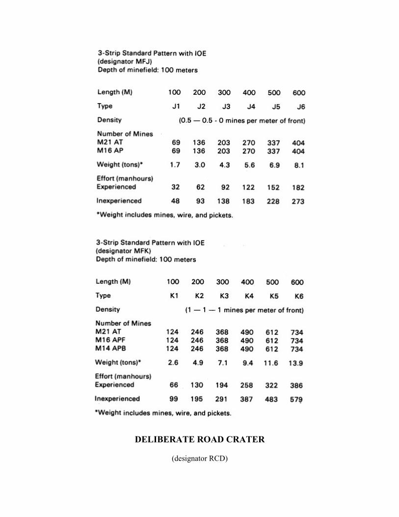
DELIBERATE ROAD CRATER
(designator RCD)

HASTY ROAD CRATER
(designator RCH)

CRATERING DEVICE (M180) WITH MINES
(designator RCM)

WIRE OBSTACLES

ABATIS
(designator ABT)

Glossary
ACE Armored Combat Earthmover
ADAM Area Denial Artillery Munition
ADM Atomic Demolition Munition
AF Air Force
ALO air liaison officer
AP antipersonnel
APC Armored Personnel Carrier
arty artillery
AT antitank
ATGM Antitank Guided Missile
AVLB Armored Vehicle Launched Bridge
bn battalion
BCE Battlefield Coordination Element
CEV Combat Engineer Vehicle
CFA covering force area
CFC Combined Forces Command
cm centimeter(s)
dia diameter
DIA Defense Intelligence Agency
DMZ demilitarized zone
DTG date-time group
ea each
ERAM Extended Range Antiarmor Munition
engr engineer
F Fahrenheit
FASCAM Family of Scatterable Mines
FEBA forward edge of the battle area
FLOT forward line of own troops
frag fragment
FROKA First Republic of Korea Army

FSCL fire support coordination line
ft foot, feet
GEMSS Ground Emplaced Mine Scattering System
HEMMS Hand Emplaced Minefield Marking Set
HQ headquarters
hr hour(s)
in inch(es)
inst instructions
IOE irregular outer edge
IRD Inzhenerny Razvedyvatel'ny Dozor (Russian for "engineer reconnaissance patrol")
KATUSA Korean Augmentation to the United States Army
kg Kilogram(s)
kg/cm² kilograms per square centimeter
kph kilometers per hour
lb pound(s)
m meter(s)
MBA Main Battle Area
METT-T mission, enemy, terrain and weather, time, and troops
min mininum
mm millimeter
MOPMS Modular Pack Mine System
mph miles per hour
NA not applicable
NATO North Atlantic Treaty Organization
NBC nuclear, biological, and chemical
NCA national command authority
NCO noncommissioned officer
OOD Otriad Obespecheniya Dvizheniya (Russian for "movement support detachment")
OP observation post
OPCON operational control
oz ounce(s)
PL phase line
POL petroleum, oils, and lubricants

POZ Podvizhnoy Otriad Zagrazhdeniya (Russian for "mobile obstacle detachment")
psi pounds per square inch
pt(s) point(s)
RAAMS Remote Anti-Armor Mine System
recon reconnaissance
ROK Republic of Korea
rpt report
SADM Special Atomic Demolition Munition
SCATMINWARN Scatterable Minefield Warning
SM scatterable mine
SOF Special Operations Forces
SOP standing operating procedures
STANAG Standardization Agreement
TACC Tactical Air Control Center
tgt target
TNT trinitrotoluene
TOE Table of Organization and Equipment
TOW tube-launched, optically tracked, wire-guided missile
TROKA Third Republic of Korea Army
US United States
WASPMS Wide Angle Side Penetrating Mining System

References
REQUIRED PUBLICATIONS
Required publications are sources which users must read in order to understand or to comply with FM 5-102.
FM 5-100 Engineer Combat Operations
FM 100-5 (HTF) Operations (How to Fight)
RELATED PUBLICATIONS
Related publications are sources of additional information. Users do not have to read them to understand FM 5-102.
Defense Intelligence Agency (DIA) Publication
DDI-1150-13-77 Soviet and Warsaw Pact River Crossing: Doctrine and Capabilities
Department of the Army Form (DA Form)
DA Form 1355 Minefield Record
DA Form 1355-1-R Hasty Protective Minefield Record
DA Form 2028 Recommended Changes to Publications and Blank Forms
Department of the Army Pamphlet (DA Pam)
DA Pam 50-3 The Effects of Nuclear Weapons
Field Manual (FM)
FM 3-87(HTF) Nuclear, Biological, and Chemical (NBC) Reconnaissance and Decontamination Operations (How to Fight)
FM 5-25 Explosives and Demolitions
FM 5-34 Engineer Field Data
FM 5-35 Engineer's Reference and Logistical Data
FM 5-36 Route Reconnaissance and Classification
FM 5-106 Employment of Atomic Demolition Munitions (ADM)

FM 5-146 Engineer Topographic Units
FM 6-20 (HTF) Fire Support in Combined Arms Operations (How to Fight)
FM 7-7 (HTF) The Mechanized Infantry Platoon and Squad (How to Fight)
FM 7-8(HTF) The Infantry Platoon and Squad (Infantry, Airborne, Air Assault, Ranger) (How to Fight)
FM 7-10(HTF) The Infantry Rifle Company (Infantry, Airborne, Air Assault, Ranger) (How to Fight)
FM 7-20(HTF) The Infantry Battalion (Infantry, Airborne, Air Assault, Ranger) (How to Fight)
FM 11-50(HTF) Combat Communications Within the Division (How to Fight)
FM 11-92 (HTF) Combat Communications Within the Corps ( How to Fight)
FM 17-95 (HTF) Cavalry (How to Fight)
FM 20-32 Mine/Countermine Operations at Company Level
FM 21-26 Map Reading
FM 21-32 Topographic Support
FM 21-40 NBC (Nuclear, Biological and Chemical) Defense
FM 24-1 (HTF) Combat Communications (How to Fight)
FM 29-12 Division Maintenance Operations
FM 29-23 Direct Support Maintenance Operations (Nondivisional)
FM 30-5 Combat Intelligence
FM 30-10 Military Geographic Intelligence (Terrain)
FM 71-1 (HTF) Tank and Mechanized Infantry Company Team (How to Fight)
FM 71-2(HTF) The Tank and Mechanized Infantry Battalion Task Force (How to Fight)
FM 71-100(HTF) Armored and Mechanized Division Operations (How to Fight)
FM 90-2 (HTF) Tactical Deception (How to Fight)
FM 90-3(HTF) Desert Operations (How to Fight)
FM 90-4(HTF) Airmobile Operations (How to Fight)
FM 90-5 (HTF) Jungle Operations (How to Fight)
FM 90-6 (HTF) Mountain Operations (How to Fight)
FM 90-10 (HTF) Military Operations on Urbanized Terrain (MOUT) (How to Fight)
FM 90-13(HTF) River Crossing Operations (How to Fight)
FM 100-2-1 Soviet Army Operations and Tactics
FM 100-2-2 Soviet Army Specialized Warfare and Rear Area Support

FM 100-2-3 Soviet Army Organization and Equipment
FM 101-5 Staff Organization and Operations
FM 101-5-1(HTF) Operational Terms and Graphics (How to Fight)
FM 101-10-1 Staff Officers' Field Manual: Organizational, Technical, and Logistic Data (Unclassified Data)
FM 101-31-1Staff Officers' Field Manual: Nuclear Weapons Employment Doctrine and Procedures
Joint Publication
TACP 50-27 and TRADOC Pamphlet 525-43, Joint Operational Concept and Procedures for Coordination of Employment of Air Delivered Mines (J-Mine)
Training Circular (TC)
TC 6-20-5 Field Artillery Delivered Scatterable Mines
PROJECTED PUBLICATIONS
Projected publications are sources of additional information that are scheduled for printing but not yet available.
Field Manual (FM)
FM 5-101 Mobility
FM 5-103 Survivability
FM 100-16 Support Operations: Echelons Above Corps
NOTE: These are publications that are scheduled for printing. Upon print, they will be distributed automatically by a pinpoint distribution and will not be available for requisition from USA-AG Publications Center, Baltimore, MD, until indexed in DA Pam 310-1.


![PIANO CONCERTO IN F 2nd Movement for Clarinets · 102 102 102 102 102 102 102 102 102 102 102 10 44 [Title]](https://img.dokumen.tips/doc/110x75/5e3946b540eed0696e2e90d2/piano-concerto-in-f-2nd-movement-for-clarinets-102-102-102-102-102-102-102-102-102.jpg)