Embed Size (px)
Citation preview

Wstable saturation in coupled quantum-dot cells P. Douglas Tougaw, Craig S. Lent, and Wolfgang Porod Department of Electrical Engineering, University of Notre Dame, Notre Dame, Indiana 46556
(Received 29 April 1993; accepted for publication 18 May 1993)
Model quantum dot cells are investigated as potential building blocks for quantum cellular automata architectures. Each cell holds a few electrons and interacts Coulombically with nearby cells. In acceptable cell designs, the charge density tends to align along one of two cell axes. Thus, a cell “polarization,” which can be used to encode binary information, is defined. The polarization of a cell is affected in a very nonlinear manner by the polarization of its neighbors. This interaction is quantified by calculating a cell-cell response function. Effects of nonzero temperature on the response of a model cell are investigated. The effects of multiple neighbors on a cell are examined and programmable logic gate structures based on these ideas are discussed.
1. INTRODUCTlON
For many years, the size of microelectronic-devices has been shrinking, and this has led to faster, denser circuits. Despite these improvements, the basic computing para- digm has remained virtually unchanged because device op- eration has been largely unaltered, apart from resealing. There is now much interest in extremely dense device ar- rays forming locally interconnected architectures like cel- lular automata (CA) ’ and cellular neural networks.’ Such architectures could lead to changes in device structure of a less evolutionary and more revolutionary nature.
At the same time, many researchers have been inves- tigating ways to use quantum structures as electronic de- vices. In the course of such research, a great deal has been learned about the behavior of electrons in very small struc- tures. Because of the size of the structures involved, an outstanding difficulty is providing a scheme in which one of these quantum devices, which typically carry nanoam- Peres of current, could be used to drive several other sim- ilar devices. In addition, the capacitance of the wires needed to interconnect such structures would tend to dom- inate their behavior. Therefore, locally connected architec- tures like CA’s may be an attractive paradigm for imple- menting quantum device architectures3
CA architectures composed of nanometer-scaled quan- tum devices that are coupled through the Coulomb iuter- action (no current flows between devices) have been pro- posed by the authors elsewhere.& We call such architectures quantum cellular automata (QCA). The QCA contains an array of quantum-dot cells that are con- nected locally by the interactions of the electrons contained within them. The quantum state of each multidot cell en- codes the “logical” state of that cell. For this reason, each cell should ideally have exactly two stable states, since this will allow direct encoding of binary information.’ Such two-state cells also need to exhibit bistable saturation to ensure that noise or small geometric variations do not over- whelm the signal.
To function as a CA, the state of each cell should be dependent on the states of its neighbors. In this paper, we compare the cell-cell coupling and bistable saturation of
several different quantum cell designs that might form the basis of quantum cellular automata. All these designs have certain characteristics in common: a few (typically four or five) quantum dots connected by coupling coefficients and populated by a total of one to three electrons. In these cells the required interaction between neighbors is caused by the mutual Coulombic repulsion of the electrons contained in the cells. We use a very simple model of each cell, neglect- ing details relating to exactly how the quantum dot struc- tures are realized, but focusing on the charge distribution among the dots and the Coulomb coupling between cells. We define a cell-cell response function that characterizes the interaction between neighboring cells.
In the next section we will introduce the theoretical model of the “standard cell,” on which much of the work of Refs. 4-6 is based. It is the most thoroughly investigated cell design because it displays strong bistable saturation. We discuss the model IIamiltonian used for the cell, the method used to calculate the cell-cell response function, and the effects of nonzero temperature. In Sec. III we com- pare various other cell designs. Among these are different geometric arrangements of the quantum dots, one and three electron cells, and continuous quantum dashes. In Sec. IV, we extend our results to include the effects of multiple neighbors on a cell. We show that such effects in a system with three nearest neighbors can be thought of as majority voting logic. We show how this behavior can be used to implement programmable logic gates, and then show other possible implementations for dedicated AND and OR gates. A discussion and conclusion follow in Sec. V.
II. A MODEL QUANTUM CELL
The model “standard cell” design, shown schemati- cally in Fig. 1 (a), consists of five quantum dots located at the corners and the center of a square. Tunneling occurs between the central site and all four of the outer sites (near-neighbor tunneling), and to a lesser degree between neighboring outer sites (next-near-neighbor tunneling). It is assumed that the potential barriers between cells are high enough to completely suppress intercellular tunneling.
3558 J. Appl. Phys. 74 (5), 1 September 1993 0021-8979/93/74(5)/3558/9/$0.00 @ 1993 American institute of Physics 3558
Downloaded 28 Mar 2007 to 129.74.250.197. Redistribution subject to AIP license or copyright, see http://jap.aip.org/jap/copyright.jsp

a)
b? P=+l P=-1
FIG. 1. Schematic of the basic five-site cell. (a) The geometry of the cell. The tunneling energy between the middle site and an outer site is desig- nated by f, while t’ is the tunneling energy between two outer sites. (b) Coulombic repulsion causes the electrons to occupy antipodal sites within the cell. These two bistable states result in cell polarizations of P= + 1 and P=-1 [SIX. Eq. (l)].
The cell is occupied by a total of two electrons hopping among the five sites; these electrons tend to occupy antip- odal outer sites within the cell due to their mutual electro- static repulsion [see Fig. l(b)].
We will show that these two stable states are degener- ate iu an isolated cell, but an electrostatic perturbation in the cell’s environment (such as that caused by neighboring cells) splits the degeneracy and causes one of these config- urations to become the cell ground state. Altering the per- turbation causes the cell to switch between the states in an abrupt and nonlinear manner. This very desirable bistable saturation behavior is due to a combination of quantum coni?nement, Coulombic repulsion, and the discreteness of electronic charge.
A. Cell polarization
Since Coulomb repulsion causes the electrons to oc- cupy antipodal sites, the ground state charge density may have the electrons aligned along one of the two diagonal axes shown in Fig. 1 (b). We therefore define the cell po- larization, a quantity that measures the extent to which the charge density is aligned along one of these axes. The po- larizat.ion is defined as
p= h+P3) - (pz+p4) - Po+p1+p2+p3+p4’
(1)
where pi denotes the electron probability density at site i. As in Fig. 1 (b), electrons completely localized on sites 1 and 3 will result in P= 1, while electrons on sites 2 and 4 yield P= - 1. An isolated cell would have a ground state that is a linear combination of these two states, and would therefore have a net polarization of zero.8
B. Model cell Hamiltonian 9
We employ a simple model of the quantum cell that uses a tight-binding Hubbard-type Hamiltonian. We rep-
resent the quantum dots as sites, ignoring any degrees of freedom internal to the dot. The Hamiltonian for a single isolated cell can be written as
W’“= c Eo ni,o+ c ti,j(ai,,taj,o+aj,oj,~) i,cl i> j,u
+ $E@i,t n,,+ ,,zc, VQ 122i:l * (2) > ? I 3
Here ai,* is the annihilation operator that destroys a parti- cle at site i (i=O,1,2,3,4) with spin IJ. The number opera- tor for site i and spin (T is represented by Q. E. is the on-site energy for each dot, tu is the energy associated with tunneling between dots i and j, and EQ is the on-site charg- ing energy (the purely Coulombic cost for two electrons of oppqsite spin to occupy the same dot). The last term in (2) represents the Coulombic potential energy due to electrons on the ith and fib sites at positions RI and Ri. VQ is an electrostatic parameter fixed by fundamental constants and the dielectric constant of the material used to form the cells.
For the cell described above we use values of the pa- rameters in the Hamiltonian based on a simple, experimen- tally reasonable model. We take E. to be the ground state energy of a circular quantum dot of diameter 10 nm hold- ing an electron with effective mass m*=0.067 m,. The near-neighbor distance between dot centers, a, is taken to be 20 nm. The Coulomb coupling strength, V,, is calcu- lated for a material with a dielectric constant of 10, and EQ is taken to be Vd( D/3).9 The coupling energy between an outer dot and the central dot is teto,j=0.3 meV (i = 1,2,3,4), and the next-near-neighbor coupling connect- ing the outer dots, t’, is taken to be t/10 (consistent with one-dimensional calculations for a barrier height of 150 meV).‘O
The spins of the two electrons in the cell can be either parallel or antiparallel. We consider here the case of elec- trons with antiparallel spins, since that is the ground state of the cell. Calculations with electrons having parallel spins yield qualitatively very similar results.
To maintain charge neutrality in the cell, a fixed pos- itive charge ii, corresponding to a charge of (2/5) e, is also assumed on each site. In a single isolated cell this just renormalizes Eo, but the fixed charge is important when simulating systems with more than one cell. If each cell had a net negative charge, then electrons near the edges of a’group of cells would respond mostly to the net negative charge of the other cells. In a semiconductor realization, the fixed positive charge would likely be provided by ion- ized donor impurities and charge on the surface of metal gates.
The interaction of a cell with its electrostatic environ- ment (including neighboring cells) is contained in a sec- ond Hamiltonian term, which we write as e,$. We solve the time-independent Schriidinger equation for the nth eigenstate of the cell, 1 Y,), under the influence of the neighboring cells:
(fC?l+C:,) I ‘u,> =E,z I ‘y,>.
3559 J. Appl. Phys., Vol. 74, No. 5, 1 September 1993 Tougaw, Lent, and Porod 3559
Downloaded 28 Mar 2007 to 129.74.250.197. Redistribution subject to AIP license or copyright, see http://jap.aip.org/jap/copyright.jsp
a- 0.0
-0.5 1 -l.OUq j
-1.0 -0.5 0.0 0.5 1.0 P*
FIG. 2. Cell-cell response function for the basic Eve-site cells shown in the inset. This shows the polarization P, induced in cell 1 by the fixed polarization of its neighbor, Pz . The solid line corresponds to antiparallel spins, and the dotted line to parallel spins. The two are nearly degenerate, especially for significantly large values of P2.
The total Hamiltonian is diagonalized directly in the basis of two-particle site kets. We calculate the single-particle density, pi, from the two-particle ground-state wave func- tion IYe) by finding the expectation value of the number operator for site i:
pi= C (YO 1 n&ml yO>- (4) rJ
We can then use these densities to calculate the cell polar- ization P as in Eq. (1).
C. Calculating the cell-cell response function
To be useful in cellular automata-type architectures, the state of a cell must be strongly influenced by the states of neighboring cells. To demonstrate how one of these cells is influenced by the state of its neighbor, consider the two cells shown in the inset to Fig. 2. The cell centers are separated by a distance of 3a=60 mn. We assume cell 2 has a given polarization P2 and that the electron density on the central site is negligible. This means that the charge density is completely determined by the cell polarization. For the corresponding electron density on each site of cell 2, we calculate the electrostatic potential at each site of cell 1. This additional potential energy is then included in the Hamiltonian for cell 1. Thus the perturbing Hamiltonian component is /
Ek.r=TU= ,,l$ 1 ~ vh,cn where
(5)
)7+ c v (pGp) k#W Q [ R,,---R,,il (6)
is the potential at site i in cell m due to the charges in all other cells. We denote the position of site j in cell k as Rkj, and the electron density at site j in cell k as p:. The total Hamiltonian for cell 1 is then
F”=Hp+~u. (7)
The two-electron time-independent Schriidinger equation is solved using this Hamiltonian for a series of values of P2
0.4
0.2
0.0
-0.2
-0.4
FIG. 3. The lowest four eigenstate energies of cell 1 induced by the polarization of cell 2. The insets show that the lowest two energy states always correspond to the same polarization direction, as in the driver. Slight exchange splitting effects between spatially symmetric and spatially antisymmetric states breaks the fourfold degeneracy for very small values of Pz.
in the range [ - 1, + 11. The ground state polarization of cell 1, PI, is then computed for each value of P2, as de- scribed in the previous section. Thus, we can plot the in- duced polarization of cell 1 as a function of the polariza- tion of cell 2. This function P, ( P2), which we call the cell-cell response function, is one measure of how well a cell will operate in a quantum cellular automaton architec- ture.
Figure 2 shows the cell-cell response function for the standard cell. The highly nonlinear nature of the response indicates that a small polarization in cell 2 causes a very strong polarization in its neighbor, cell 1. The figure also shows that the polarization of cell 1 saturates very quickly to a value of + 1 or - 1. This bistable saturation is the basis of the quantum cellular automata, since it means that we can encode bit information using the cell polarization. We assign the bit value of 1 to the P= + 1 state and the bit value 0 to the P= - 1 state. Since the cell is almost always in a highly polarized state ( ] PI = l), the state of the cell will be indeterminate only if the electrostatic environment due to other cells is perfectly symmetric.
Figure 3 shows the lowest four eigenenergies of cell 1 as a function of the polarization of cell 2. This shows that the perturbation due to the polarization of cell 2 quickly separates the states of opposite polarization. For a com- pletely polarized standard cell, the excitation energy from the ground state to the first excited state with opposite polarization is about 0.8 meV. This corresponds to a tem- perature of about 9 K.
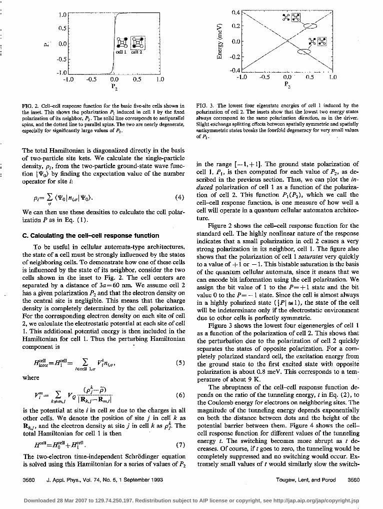
The abruptness of the cell-cell response function de- pends on the ratio of the tunneling energy, t in Eq. (2), to the Coulomb energy for electrons on neighboring sites. The magnitude of the tunneling energy depends exponentially on both the distance between dots and the height of the potential barrier between them. Figure 4 shows the cell- cell response function for different values of the tunneling energy t. The switching becomes more abrupt as t de- creases. Of course, if t goes to zero, the tunneling would be completely suppressed and no switching would occur. Ex- tremely small values of t would similarly slow the switch-
3560 J. Appl. Phys., Vol. 74, No. 5, 1 September 1993 Tougaw, Lent, and Porod 3560
Downloaded 28 Mar 2007 to 129.74.250.197. Redistribution subject to AIP license or copyright, see http://jap.aip.org/jap/copyright.jsp
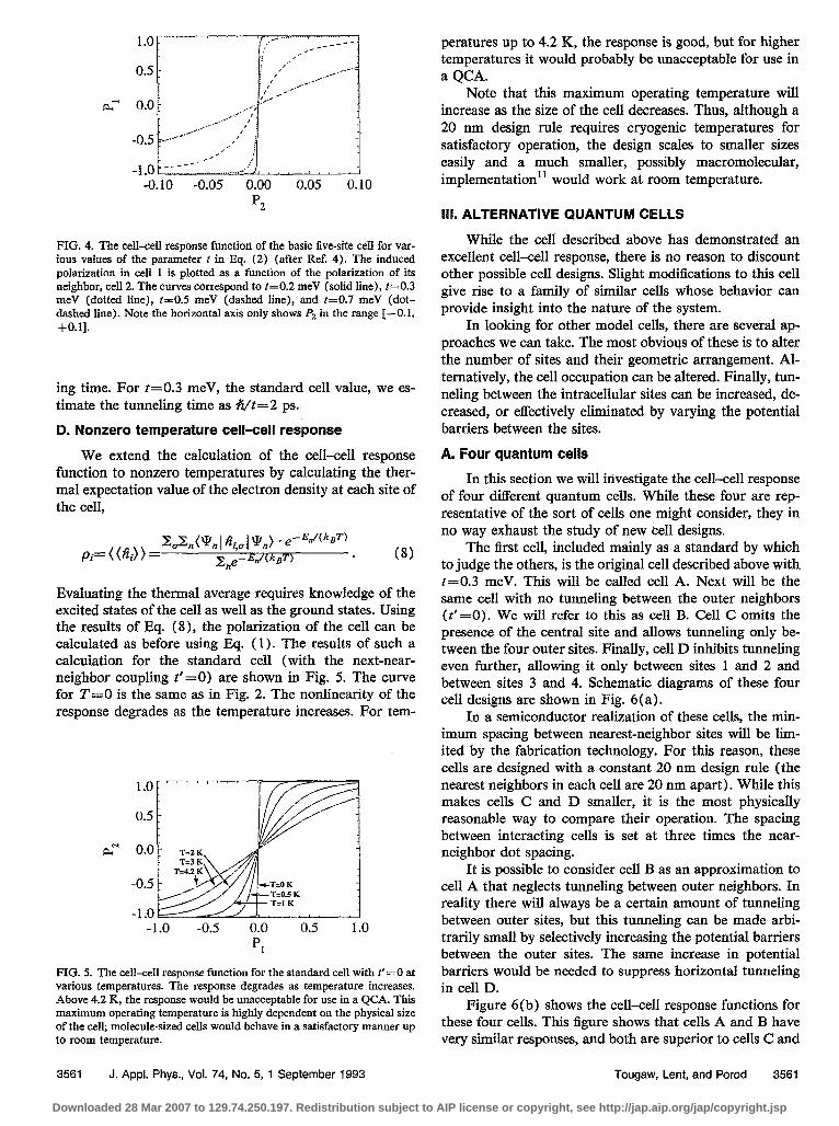
FIG. 4. The cell-cell response function of the basic flve-site cell for var- ious values of the parameter f in F$ (2) (after Ref. 4). The induced polarization in cell 1 is plotted as a function of the polarization of its neighbor, cell 2. The curves correspond to t=0.2 meV (solid line), k0.3 meV (dotted line), k0.5 meV (dashed line), and k0.7 meV (dot- dashed line). Note the horizontal axis only shows P2 in the range [-0.1, +0.1].
ing time. For t=0.3 meV, the standard cell value, we es- timate the tunneling time as +i/t=2 ps.
D. Nonzero temperature cell-cell response
We extend the calculation of the cell-cell response function to nonzero temperatures by calculating the ther- mal expectation value of the electron density at each site of the cell,
T3,(YnI &I WJ * e --E,/(kgT) pi” ( (Ai) > = -+e-WW-) * (8)
Evaluating the thermal average requires knowledge of the excited states of the cell as well as the ground states. Using the results of Eq. (8), the polarization of the cell can be calculated as before using Eq. ( 1). The results of such a calculation for the standard cell (with the next-near- neighbor coupling t’=O) are shown in Fig. 5. The curve for T==O is the same as in Fig. 2. The nonlinearity of the response degrades as the temperature increases. For tem-
-1.0 -0.5 0.0 0.5 1.0 PI
FIG. 5. The cell-cell response function for the standard cell with t’ =0 at various temperatures. The response degrades as temperature increases. Above 4.2 K, the response would be unacceptable for use in a QCA. This maximum operating temperature is highly dependent on the physical size of the cell; molecule-sized cells would behave in a satisfactory manner up to room temperature.
3561 J. Appl. Phys., Vol. 74, No. 5, 1 September 1993 Tougaw, Lent, and Porod 3561
peratures up to 4.2 K, the response is good, but for higher temperatures it would probably be unacceptable for use in a QCA.
Note that this maximum operating temperature will increase as the size of the cell decreases. Thus, although a 20 nm design rule requires cryogenic temperatures for satisfactory operation, the design scales to smaller sizes easily and a much smaller, possibly macromolecular, implementation” would work at room temperature.
111. ALTERNATIVE QUANTUM CELLS
While the cell described above has demonstrated an excellent cell-cell response, there is no reason to discount other possible cell designs. Slight modifications to this cell give rise to a family of similar cells whose behavior can provide insight into the nature of the system.
In looking for other model cells, there are several ap- proaches we can take. The most obvious of these is to alter the number of sites and their geometric arrangement. Al- ternatively, the cell occupation can be altered. Finally, tun- neling between the intracellular sites can be increased, de- creased, or effectively eliminated by varying the potential barriers between the sites.
A. Four quantum cells
In this section we will investigate the cell-cell response of four different quantum cells. While these four are rep- resentative of the sort of cells one might consider, they in no way exhaust the study of new bell designs.
The first cell, included mainly as a standard by which to judge the others, is the original cell described above with t=0.3 meV. This will be called cell A. Next will be the same cell with no tunneling between the outer neighbors (t’=O). We will refer to this as cell B. Cell C omits the presence of the central site and allows tunneling only be- tween the four outer sites. Finally, cell D inhibits tunneling even further, allowing it only between sites 1 and 2 and between sites 3 and 4. Schematic diagrams of these four cell designs are shown in Fig. 6 (a).
In a semiconductor realization of these cells, the min- imum spacing between nearest-neighbor sites will be lim- ited by the fabrication technology. For this reason, these cells are designed with a constant 20 nm design rule (the nearest neighbors in each cell are 20 nm apart). While this makes cells C and D smaller, it is the most physically reasonable way to compare their operation. The spacing between interacting cells is set at three times the near- neighbor dot spacing.
It is possible to consider cell B as an approximation to cell A that neglects tunneling between outer neighbors. In reality there will always be a certain amount of tunneling between outer sites, but this tunneling can be made arbi- trarily small by selectively increasing the potential barriers between the outer sites. The same increase in potential barriers would be needed to suppress horizontal tunneling in cell D.
Figure 6(b) shows the cell-cell response functions for these four cells. This figure shows that cells A and B have very similar responses, and both are superior to cells C and
Downloaded 28 Mar 2007 to 129.74.250.197. Redistribution subject to AIP license or copyright, see http://jap.aip.org/jap/copyright.jsp

-, CELL A CELL B CELL c CELL D
a*
b)
1.0
0.5
0.0
-0.5
-1.0
FIG. 6. Four geometric variations on the simple model quantum cell. (a) Schematic diagrams of the four cells. Cells C and D occupy less area, but all four cells are drawn with the same minimum spacing between neigh- bors. Cells B and D will require potential variation between the sites to selectively inhibit tunneling. (b) The cell-cell response function for each of these cell designs. Cell B has the best response, but the improvement over A is small.
D. Thus, elimination of the central site as in cells C and D degrades the response. This leads us back to the five-site cell we originally considered. Since the complete suppres- sion of next-near-neighbor coupling as in cell B might in- troduce additional fabrication difficulty with little improve- ment in the cell response, cell A may be the most practical of these four cell designs.
B. One- and three-electron cells
As an alternative to changing the geometry of the cell, we can also alter the electron occupancy. Figure 7 shows the cell-cell response function for cell A occupied by a single electron, and Fig. 8 shows the response for the same cell with three electrons (two parallel spins, one antipar- allel) . These nearly linear response functions never become
L--2 a- 0.0
-0.5 E
p2 FIG. 7. The cell-cell response function for the basic five-site cell occupied by a single electron. The weak response indicates that such a cell is unsuitable as the basis of a QCA.
-l.OL I cL_ -I_. i -0.5 0.0 0.5
P2
FIG. 8. Cell-cell response function for the basic five-site cell occupied by three electrons. Such a cell is also unacceptable as the basis of a QCA.
strongly polarized, even for fully polarized neighbors. This indicates that such cells would perform very poorly as the basis of a quantum cellular automaton.”
C. Quantum dashes and double wells
Proposals have been made for one-electron “quantum dash” cells that appear qualitatively similar to the cells we have discussed here.13 In this section we investigate the cell-cell response function of single-electron quantum dashes and compare this to a very similar double quantum well to show how important the discreteness of electronic charge is to the nonlinearity of the response functions seen in the previous sections.
Since these cells are of a more spatially continuous nature than cells previously considered, the site represen- tation is no longer useful. Each cell will be modeled as a one-dimensional hard-walled square well of width 30 mu. The two cells are separated by a distance of 20 nm. These dimensions are similar to those of the cells described above. We use the finite element method to solve the single- electron time-independent Schriidinger equation for each one-electron cell. The geometry used to calculate the cell- cell response function is shown schematically in Fig. 9 (a).
Since these cells have only a single axis along which to distribute the electronic charge, a new definition of polar- ization must be introduced. The new detlnition, which takes into account the continuous nature of the probability density, is
p= soI& p(xw+- Sf$%(X)~~ SoLPW~~ -
cq>
Because of its continuous nature, the charge density in the “driver” cell is no longer uniquely determined by specify- ing the cell polarization. We therefore fix the charge den- sity to be constant in each half of the driver cell.
The cell-cell response function calculated for such a system is shown in Fig. 9(b). As this figure shows, the response is quite linear, and cell 1 is virtually unpolarized, even for a fully polarized neighbor. The electron probabil- ity density as a function of position for cell 1 with a fully polarized neighbor (P2= 1) is shown in Fig. 9(c). The probability density is nearly symmetric about the center of the cell as we would expect for such a small polarization.
3562 J. Appl. Phys., Vol. 74, No. 5, 1 September 1993 Tougaw, Lent, and Porod 3562
Downloaded 28 Mar 2007 to 129.74.250.197. Redistribution subject to AIP license or copyright, see http://jap.aip.org/jap/copyright.jsp

Cell 1 Cell 2 Cell 1 Cell2
T 30 nm
i
20 nm
b) -of&--z-~ 1.0
Position (nm)
FIG. 9. The “quantum dash” as a QCA cell. (a) A schematic diagram of the cellular arrangement. The length and spacing is similar to that of the basic five-site cell in Fig. 1 (a). Each cell is modeled as a one-dimensional infinite square well. The cell-cell response is shown in (b). Note that the vertical axis only shows P2 over the range [-O.l,+O.l]. (c) The one- dimensional charge density in cell 2 for a fully polarized neighbor (PI = 1). The nearly symmetric charge density yields a very low polar- ization.
A related cell, the double well, is shown schematically in Fig. 10 (a). It is a quantum well of the same dimensions as in Fig. 9(a), but the potential in the middle third of the well has been raised by 150 meV. This cell is also very similar to half of cell D from the last section, so we would expect its response to be much better than that of the sim- ple quantum dash.
The calculated response, shown in Fig. 10(b), is in- deed much better than that of Fig. 9(b). Its nonlinearity and saturation properties are very similar to those of cells C and D in Fig. 6(b). This response shows that one- electron cells can be used to provide the required nonlinear response, but it is also possible to view each pair of these cells as a single two-electron cell, which becomes geomet- rically very similar to cell D of Fig. 6 (a).
The fact that such a seemingly small change in the nature of the cell should cause such a profound change in the cell-cell response function is linked to the fact that electron charge is discrete in regions surrounded by high potential barriers. That is to say, the expectation value of the number operator approaches an integer value as the region becomes more and more isolated by the potential
a> 20 nm
30 nm
c> 8 1 -15 0 15 Position (run)
FTG. 10. The double well as a QCA cell. (a) A schematic diagram of the cellular arrangement. The total dimensions are identical to those of Fig. 8. The middle third of each cell contains a 150 meV barrier to isolate the top and bottom of the cell. (b) The cell-cell response function for such an arrangement. Note that the vertical axis now shows P2 over the range [- 1.0, + 1.01. (c) The one-dimensional charge density in cell 2 for a fully polarized neighbor (PI = 1). The highly asymmetric charge density re- sults in a cell that is almost completely polarized.
barriers surrounding it. I4 Therefore, almost the entire wavefunction will become localized in one-half of the cell if a small asymmetry in the electrostatic environment is in- troduced. This fact is demonstrated in Fig. 10(c), which shows nearly all the charge density on the right half of the cell. Since there is no barrier in the middle of the quantum dash to isolate the top and bottom of the cell, no such localization behavior is seen there, and the charge density is always nearly symmetric about the center of the well.
IV. MULTIPLE NEIGHBOR INTERACTIONS
Thus far, we have only considered the interaction be- tween a cell and a single neighboring cell. The natural extension of this is to investigate the effects of multiple neighbors on the state of a cell. Since this implies consid- ering a system that contains several cells and therefore several electrons, we cannot use the direct solution method described earlier for treating a single cell. For the analysis of such systems, we treat the physics within each cell as before, including exchange and correlation effects exactly. The intercellular interaction is treated self-consistently us-
3563 J. Appl. Phys., Vol. 74, No. 5, 1 September 1993 Tougaw, Lent, and Porod 3563
Downloaded 28 Mar 2007 to 129.74.250.197. Redistribution subject to AIP license or copyright, see http://jap.aip.org/jap/copyright.jsp

FIG. Il. Majority voting logic. The states of the center and right cells are always the same as the majority of the three t&d neighbors. The cells with heavy borders have fixed charge densities. These are not schematic diagrams; they are the actual results of the ICHA solution of the ground state charge densities in this system. The diameter of each dot is propor- tional to the charge density on that site.
ing a Hartree approximation. This method, called the In- I tercellular Hartree Approximation (ICHA) is detailed in
Refs. 5 and 6. Figure 11 shows an arrangement of standard cells,
such that one cell has multiple neighbors. The charge den- sities of the cells on the top, left, and bottom are fixed, while those of the middle and right cells are free to react to the tixed charge. In an actual QCA, the states of the neigh- bors would not be fixed; they would be driven by the re- sults of previous calculations or come from inputs at the edge of the QCA.
In the specific state shown in Fig. 11, two of the fixed neighbors are in the “one” state, and the other is in the “zero” state. When the ICHA is used to determine the ground state of this system, we find that the states of the center and right cells match the state of the majority of the tied neighbors. We refer to this feature of the cell behav- ior, which is true for all combinations of the three inputs, as majority voting logic. Note that Figs. 11-13 are not sche- matic,. but plots of the self-consistent electron density on each site. The radius of each dot is proportional to the single-electron density at that site.
I
Input A
Program Line 11 0
h
El l.f&l q l&r;ill .
9 . . q
1 l 1
FIG. 12. The programmable AND/OR gate. The program line is set to one in each system, so the gate is displaying OR logic. All four combi- nations of the nonprogram line inputs are shown. The cells with heavy borders have 6xed charge densities. Any one of the three inputs could be the program line; the left cell is not special. These are not schematic diagrams; they are the actual results of the ICHA sohttion of the ground state charge densities in each system. The diameter of each dot is propor- tional to the charge density on that site.
3564 J. Appl. Phys., Vol. 74, No. 5, 1 September 1993
1pJ
FIG. 13. The nonprogrammable AND gate. All four combinations of the inputs are shown. The cells with heavy borders have Exed charge densi- ties, while those with dotted borders are geometrically biased toward zero as shown in the inset. The bias is sufficient to decrease the on-site energy of the affected sites by 1%. Note that the output only equals one if both of the inputs are also one. These are not schematic diagrams; they are the actual ICHA results of the ground state charge densities in each system. The diameter of each dot is proportional to the charge density on that site.
While majority voting logic behavior is valuable by itself, its potential functionality is shown by a particular interpretation of the three inputs. In Fig. 12, we have sin- gled out one of the three and called it the program signal. Note that any one of the three neighbors could serve as the program signal, but the one case we are showing (with the program line coming in from the left) is sufficient for il- lustration purposes. The four systems shown include all possible combinations of signals on the two nonprogram lines. Since all four systems in Fig. 12 show the program line in the “one” state, the central cell can only be zero if the other two inputs are both zero. Thus the system real- izes the truth table of the OR operation. Likewise, if the program signal is zero, the result is zero unless both of the other inputs are one. This is a realization of the AND operation.
By interpreting any one of the inputs as a program line, we have implemented a programmable AND/OR gate. The nature of this gate (AND versus OR) is defined by the state of the program line, and the other two inputs are applied to the gate thus defined.
The fact that the rightmost cell always matches the central cell means that the result of this calculation can be propagated away from the gate, down a QCA rcwire,“15 and eventually serve as the input to subsequent gates. It is necessary to distinguish between driving neighbors .and driven neighbors in this system. Since the rightmost cell is free to react to the states of its neighbors, it is a driven neighbor. Its state will always match that of the central cell, so only the three driving neighbors are involved in the
Tougaw, Lent, and Porod 3564
Downloaded 28 Mar 2007 to 129.74.250.197. Redistribution subject to AIP license or copyright, see http://jap.aip.org/jap/copyright.jsp

majority voting. Of course, once the signal is propagated away from this gate, the outgoing cells are being driven and can be used as driving neighbors for subsequent gates.
A dedicated, nonprogrammable implementation of the AND gate is shown in Fig. 13. This system has only two driving inputs; there is no program signal. The role previ- ously played by the program signal, biasing the central cell so it can only be in the one state if both of its neighbors are, is performed by slightly enlarging the two quantum dots on sites 1 and 3 in the central cell.16 This means that the ground state of the isolated cell is no longer an unpolarized state; the cell is biased toward the zero state and can only be persuaded to enter the one state if both of its driving neighbors are one. Again, the signal propagates away to the right and can be used to drive subsequent gates. A dedicated OR gate can similarly be implemented by enlarg- ing sites 2 and 4, biasing the cell toward the one state. It will only be in the zero state if both of its driving neighbors are also zeros.
V. DISCUSSION
With the above results, we have demonstrated several quantum-dot cells suitable for implementing a quantum cellular automata architecture. Examination of the cell- cell response function shows that for appropriate cell de- signs, the state of a cell is influenced very strongly by the state of its neighbors. The highly nonlinear response of the cell suggests that a signal that has become degraded by noise will be restored to full polarization by subsequent cells in the array.15 In this way, the bistable saturation of the quantum cell is analogous to the gain in a conventional digital device.
We have assumed throughout that the many electron system is in its ground state. In general, a system will start in the ground state and then be driven into an excited state by externally changing the states of input cells near the edge of a QCA array. Inelastic processes, which are usually very detrimental to the operation of quantum devices, then drive the system back to a new ground state corresponding to the new inputs. The details of the temporal evolution of the many-electron system as it relaxes to its ground state are very complicated. In the QCA scheme, we rely on the properties of the system ground state and not the details of the relaxation process for doing the computation. This idea of “computing with the ground state” and the related con- cept of “edge-driven” systems are discussed more thor- oughly in Ref. 5.
The behavior of lines of these cells, the most basic (and important) components of a quantum cellular automaton, is discussed in Ref. 6. The results show an excellent exam- ple of the restoration of full signal strength after degrada- tion by noise. In addition, it shows that the particular set of parameters we chose in Sec. II B is not critical; there is a wide range of parameter values for which the cells transmit information from one cell to another..
Clearly, fabrication of these devices presents a major challenge in the realization of QCA devices, but semicon- ductor realizations of such systems using new nanolitho- graphic techniques should be possible. It is also possible
that future realizations of these cells will be on a macro- molecular basis. Another challenge, sensing the presence or absence of a single electron without disturbing the sys- tem, necessary for reading the output state of a QCA de- vice, has been successfully addressed. I7
In conclusion, we have explored the interaction of neighboring quantum-dot cells. We have defined the cell- cell response function, which characterizes the nonlinearity of the coupling between cells, and thus determines suitabil- ity of a particular cell design for quantum cellular autom- ata implementations. Several cell designs that exhibit the required nonlinear response and bistable saturation have been examined. Temperature effects degrade cell perfor- mance, but analysis in this simple model suggests that op- eration at 4.2 K should be within the reach of semiconduc- tor implementations. When a cell has several neighbors, its state is determined by the state of the majority of the neigh- boring cells. This majority voting logic makes possible the construction of programmable AND/OR logic gates as well as dedicated AND and OR gates.
ACKNOWLEDGMENTS
We gratefully acknowledge stimulating conversations with Gary H. Bernstein of the Notre Dame Nanoelectronic Group. This work was supported in part by the Air Force Office of Scientific Research and the Office of Naval Re- search. This material is based in part upon work supported under a National Science Foundation Graduate Fellow- ship.
‘T. Toffoli and N. Margolus, Cellular Automata Machines: A New En- uironment for Modeling (MIT Press, Cambridge, MA, 1987).
‘L. D. Chua and L. Yang, IEEE Trans. Circuits Syst. 35, 1257, 1273 (1988).
‘R. T. Bate, Bull. Am. Phys. Sot. 22, 407 (1977); J. N. Randall, M. A. Reed, and G. A. Frazier, J. Vat. Sci. Technol. B 7, 1398 (1989); D. K. Ferry, L. A. Akers, and E. W. Greeneich, Ultra Large Scale Intercon- nected Microelectronics (Prentice+Hall, Englewood Cliffs, NJ, 1988); J. N. Randall, A. C. Seabaugh, Y.-C. Kao, J. H. Luscombe, and B. L. Newell, J. Vat. Sci. Technol. B 9, 2893 (1991).
%. S. Lent, P. D. Tougaw, and W. Porod, Appl. Phys. Lett. 62, 714 (1993).
‘C. S. Lent, P. D. Tougaw, W. Porod, and G. H. Bernstein, Nanotech- nol. 4, 49 (1993).
6C. S. Lent and P. D. Tougaw, (unpublished). ‘Others have attempted to apply our QCA architecture ideas (Refs. 4-6)
to a system where the information is encoded in the spin of the electron. See S. Bandyopadhyay, B. Das, and A. Miller (unpublished).
‘The polarization so detined is not to be confused with a dipole moment. For the situations we consider here, the ground state of the cell has no dipole moment, though it may have a quadrupole moment. The cell polarization simply measures the degree to which the electronic charge is aligned and the direction of that alignment.
‘For the standard cell, we take Eo to be the Coulomb energy of two electrons separated by one-third the dot diameter D, a physically rea- sonable iirst approximation.
“Reference 6 examines the behavior of lines of cells as all these Hamil- tonian parameters are varied. The bistable behavior we examine here is not critically dependent on a particular choice of these parameters, but holds for a wide range of parameter choices.
“For a review of the current state, see G. J. Ashwell, Ed., Molecular Electronics (Wiley, New York, 1992).
“Control of cell occupancy ,is clearly important in implementation. The abiity to control quantum dot occupancies over as many as lo* dots using a backgating technique has recently been reported by B. Meurer, D. Heitmann, and K. Ploog, Phys. Rev. Lett. 68, 1371 (1992).
3565 J. Appl. Phys., Vol. 74, No. 5, 1 September 1993 Tougaw, Lent, and Porod 3565
Downloaded 28 Mar 2007 to 129.74.250.197. Redistribution subject to AIP license or copyright, see http://jap.aip.org/jap/copyright.jsp
r3P Bakshi, D. A. Broido, and K. Kempa, J. Appl. Phys. 70, 5150 (i991).
14See the discussion and two-electron calculation by C. S. Lent, in Nano- structures and Mesoscopic Systems, edited by W. P. Kirk and M. A. Reed (Academic, Boston, 1992), p. 183.
“See the discussion of the behavior of lines of cells as a binary wire in Ref. 6.
r6Enlarging the quantum dots lowers the on-site energy EO and makes it energetically more favorable to occupy the larger dots.
“Noninvasive probing of single-electron charging in a semiconductor quantum dot has recently been reported by M. Field, C. G. Smith, M Pepper, J. EL F. Frost, G. A. C. Jones, and D. G. Hasko, Phys. Rev. Lett 70, 1311 (1993).
3566 J. Appl. Phys., Vol. 74, No. 5, 1 September 1993 Tougaw, Lent, and Porod 3566
Downloaded 28 Mar 2007 to 129.74.250.197. Redistribution subject to AIP license or copyright, see http://jap.aip.org/jap/copyright.jsp


![New Journal of Physics - ETH Zihn/papers/njp7_5_111.pdfdot [18, 19], an Aharonov–Bohm ring with a side-coupled quantum dot [20] and a series of experiments in which a quantum dot](https://img.dokumen.tips/doc/110x75/5f69445389d14477fa22eefc/new-journal-of-physics-eth-z-ihnpapersnjp75111pdf-dot-18-19-an-aharonovabohm.jpg)