Embed Size (px)
DESCRIPTION
biomassa
Citation preview

JEE651 Biomass for Heat and PowerSemester 1/2006
Lecture 2: Thermal conversion technologies
Dr. Suneerat Pipatmanomai

Biomass conversion
• Biomass can be converted into liquid, solid and gaseous fuels with the help of some physical, chemical and biological conversion processes
• The objective is to transform a carbonaceous solid material which is originally difficult to handle, bulky and low energy content, into fuels having characteristics which permit economic storage and transferability through pumping systems
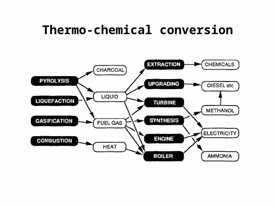
Thermo-chemical conversion

• Thermochemical conversion technologies and products

Biomass combustion
• About biomass combustion– Combustion is a mature and widely disseminated
technology, having been commercially available for more than 100 years
– Today, in all parts of the world, the predominant route for generating electricity from biomass is based on steam turbine technology, which comprises approximately 40 gigawatts of generating capacity

• Biomass combustion technology– Essentially the same technology is used to generate power
from coal, making the steam turbine a foundation of the global electric sector
– Biomass is burned, if not for heat, to produce steam, and the steam turns a turbine and the turbine drives a generator, producing electricity
– Typically, biomass systems range from a single megawatt (e.g. 5 kW for domestic woodstoves) to tens of megawatts (for electricity generation), and rarely to hundreds of megawatts (e.g. 500 MW CFB boilers)
– Systems for biomass applications tend towards the smaller range because sources of biomass are generally dispersed
– Because of potential ash build-up (which fouls boilers, reduces efficiency and increases costs), only certain types of biomass materials are used for direct combustion

• Biomass combustion characteristics– Tolerant of wide variety of feed compositions and
moisture contents– Emissions issues, especially particulates and NOx– Low efficiency for electricity (20%-30%, depending on
scale)– Strong scale economies on capital cost– Compared to solid fossil fuels, biomass has lower
heating value, since it has less carbon but more oxygen

The chemistry of biomass combustion
• Combustion is a series of chemical reactions by which carbon is oxidized to carbon dioxide, and hydrogen is oxidized to water
• In addition to volatile and nonvolatile combustible compounds, biomass contains compounds which do not burn and survive combustion in a solid form called “ash”
• Three different processes of coal combustion
a) Pyrolysis: generates volatile (tar + gas) and char
b) Burning of volatile compounds
c) burning of the char

Pyrolysis/Devolatilisation
• Pyrolysis is defined as thermal degradation of organic materials in the absence of O2
• It is an early stage of all combustion and gasification processes due to the high heat transfer compared to mass transfer
• Pyrolysis produces a hydrocarbon-rich gas mixture, an oil-like liquid and a carbon-rich solid residue

• Reaction mechanisms of biomass pyrolysis can be defined in 5 stages:
Moisture and some volatile loss
Breakdown of hemicellulose; emission of CO and CO2
Exothermic reaction raising the biomass temperature; emission of methane, hydrogen and ethane
External energy is now required to continue the process
Complete decomposition occurs

• Pyrolysis is governed by many physicochemical processes, such as – the structure of biomass (e.g. pore size, intrinsic reactivity)– transport processes in the pores and at the surface of
biomass particles – temperature during pyrolysis– secondary reaction of the pyrolysis products

Burning of volatile compounds
• The volatile compounds, which are formed during pyrolysis, are burnt in the gas phase
• The governing processes are similar to those of droplet combustion, which are evaporation, diffusion into the gas phase and combustion
• Volatile compounds are a mixture of unknown composition, therefore a detailed description based on simple kinetics is not possible
• Methane combustion is, however, famously used to represent the burning of volatiles

Burning of char
• Major reaction path is the oxidation of surface carbon by gas phase CO2 or O2 to form CO
• CO, now attached to the oxygen and weakly attached to carbon, leaves the carbon surface to the gas phase where CO can be further oxidized to CO2
• Mechanism of char burning includes - Adsorption of molecules on the surface- Surface reactions- Desorption of the products - Diffusion through the pores- Diffusion at the particle surfaces
Industrial biomass combustion
• Furnace – The simplest combustion technology– In a furnace, biomass fuel burns in a combustion chamber,
converting biomass into heat energy– The hot gases released from combustion contain about
85% of the fuel’s potential energy – Commercial and industrial facilities use furnaces for heat
either directly or indirectly through a heat exchanger in the form of hot air or water
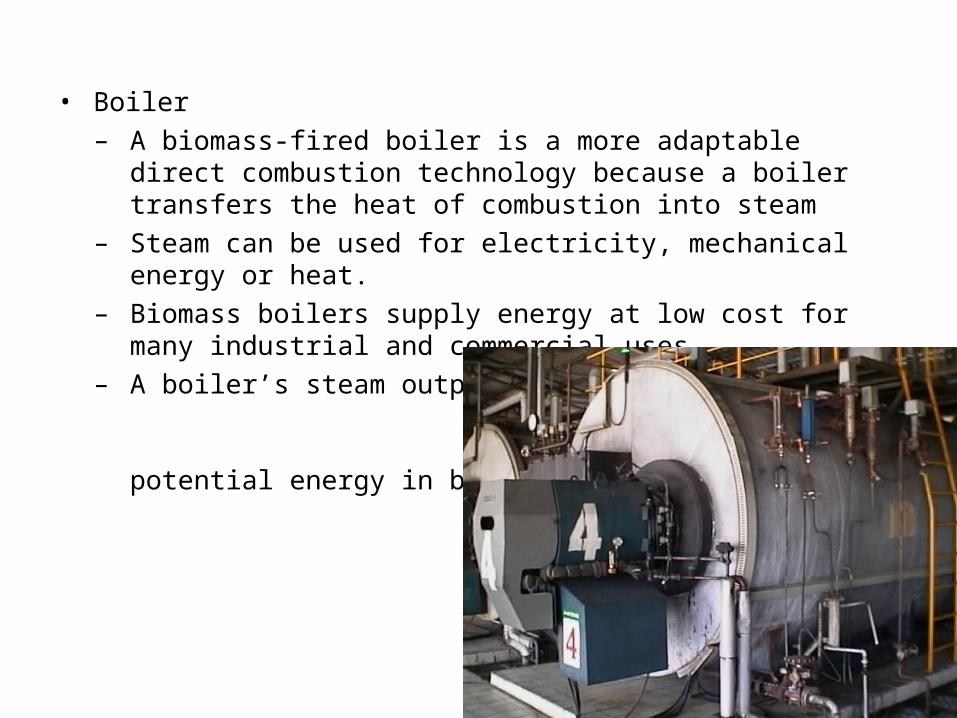
• Boiler – A biomass-fired boiler is a more adaptable direct combustion
technology because a boiler transfers the heat of combustion into steam
– Steam can be used for electricity, mechanical energy or heat.
– Biomass boilers supply energy at low cost for many industrial and commercial uses
– A boiler’s steam output contains 60 to 85 % of the potential energy in biomass fuel

Combustion equipment
• Additional equipment is often attached to the boiler
- A Stoker consists of a screw or a piston working in connection between a fuel storage and a retort in the bottom of the boiler. The fuel must not have a too high moisture content in a stoker. In small stokers, dried fuel chips with a moisture content of 25 to 35 % can be burned.

- With Pre-oven, not completely combusted gas is transferred from the pre-oven to the boiler through a connecting channel. The pre-oven is often necessary for wet fuels with a moisture content higher than around 40 %.
- Pulverised fuel burners may be interesting in the future for small boilers. Currently pulverised fuel burners are only used in large installations. Pulverised wood burners are normally used to retrofit oil or coal boilers.

- Combustion boilers are available in different designs depending on application and biomass characteristics.
- The main technological options are to burn the biomass on a grate (either fixed or moving), or to fluidize the biomass with air or some other medium to provide even and complete burning.

Grate furnace
• Grate furnace is the most common type of equipment for capacities > 500 kW. There are various types of grates.
• One can distinguish boilers with a stationary sloping grate, a travelling grate and a vibrating grate. Common to these types is a fuel feeding system which puts a layer of fuel on the grate which is relatively small and more evenly distributed than in the case of pile burners.
• The most common fuel type used in grate boilers is wood chips, but also mixtures of wood chips/peat, wood chips/shavings from saw-mills, briquettes and agricultural residues.

• In a stationary sloping grate boiler:
- The grate does not move, but the fuel burns as it slides down the slope.
- It is most commonly used at capacities lower than 1 to 2 MW.
- Since the slope of the grate should be different for different types of fuel, or even for the same type of fuel which is prepared in different ways, this type of grate is not very flexible.
- Disadvantages of this type of boiler are the difficult control of the combustion process and the risk of avalanching of the fuel.

• In a travelling grate boiler:
- The fuel is fed on one side of the grate and has to be burned when the grate has transported it to the ash dumping site of the furnace.
- Because of the small layer of fuel on the grate, carbon burnout efficiency is also better in comparison with the stationary sloping grate boiler.
- The moving grate is commonly used at capacities larger than 1-2 MW.
- Since the fuel bed is mixed mechanically, moving grates are more fuel flexible than fixed grates. For fuels with high contents of ash and varying particle sizes, a moving sloping grate should be used.

• With a vibrating grate boiler:– The fuel is fed evenly on the whole grate. The grate has a
kind of shaking movement which spreads the fuel evenly– This type of grate has less moving parts than a travelling
grate and therefore has lower maintenance requirements – Advantages:
• Recent boilers use water-cooled vibrating grates, allowing the use of high temperature undergrate air and a higher percentage of overfire air, enabling lower combustion temperature operations and therefore better control of NOx formation
• Lower quantities of underfire air also lower unburned particle carry-over

Grate furnace/boiler
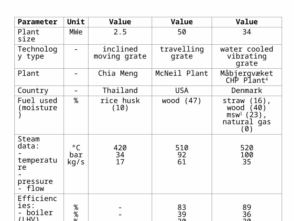
Parameter
Unit Value Value Value
Plant size MWe 2.5 50 34Technology type
- inclined moving grate
travelling grate
water cooled vibrating grate
Plant - Chia Meng McNeil Plant Måbjergvæket CHP Plant4
Country - Thailand USA DenmarkFuel used (moisture)
% rice husk (10) wood (47) straw (16), wood (40)
msw1 (23), natural gas (0)
Steam data:- temperature- pressure- flow
°Cbarkg/s
4203417
5109261
52010035
Efficiencies:- boiler (LHV)- turbine (gross)- net (LHV)
%%%
---
833930
893630
Investment costs (1992 US$)
$/kWe
15502 1800 2900
Emissions:- NOx - CO - particulates
mg/Mjinmg/Mjinmg/Mjin
1503
333
-
74177
4
108130
-
Fluidised beds
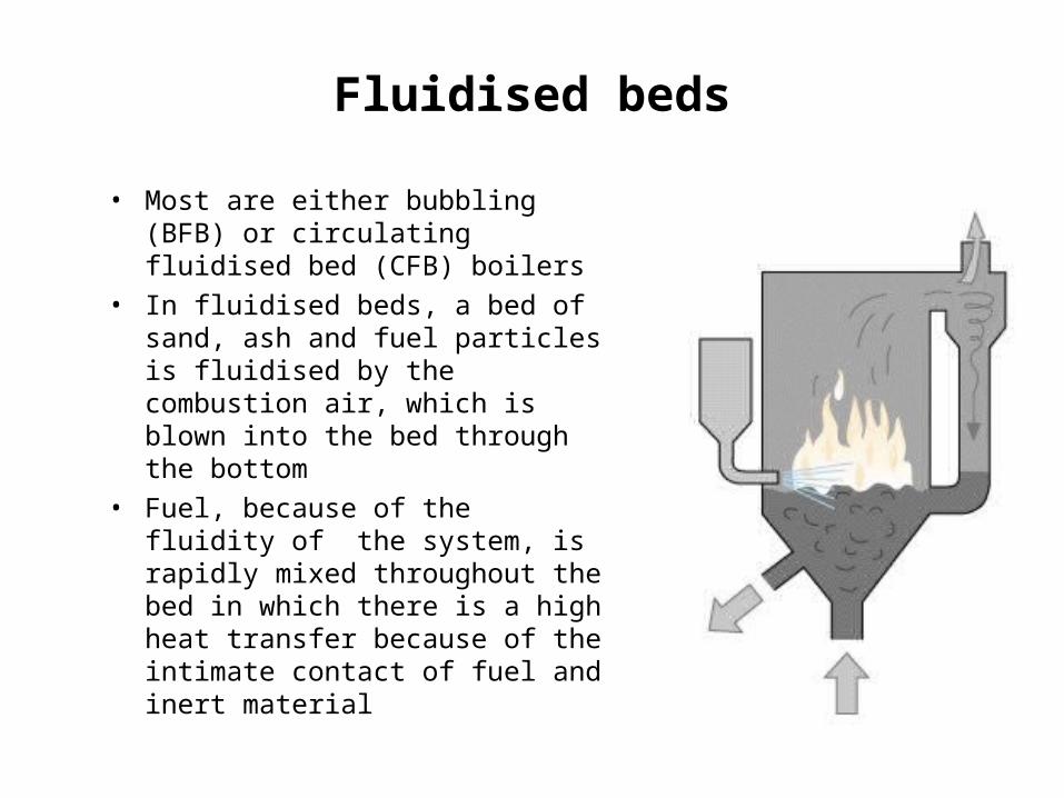
• Most are either bubbling (BFB) or circulating fluidised bed (CFB) boilers
• In fluidised beds, a bed of sand, ash and fuel particles is fluidised by the combustion air, which is blown into the bed through the bottom
• Fuel, because of the fluidity of the system, is rapidly mixed throughout the bed in which there is a high heat transfer because of the intimate contact of fuel and inert material

Fluidised bed
• Advantages: – Combustion can take place with a minimum of excess air
and at a low combustion temperature, typically 800-900C, as compared with stoker fired boilers
– Another advantage of the fast heat transfer is that the installations have relatively high capacity at a relatively small volume.
– Fluidised bed boilers will be very flexible with respect to moisture content, ash content and size of the fuel, because of the usage of inert medium and the relatively low amount of fuel compared to the total bed mass.

– The operating temperatures in FBC boilers are well below the formation point of thermal induced nitrogen oxides. Fuel bound NOx formation can be reduced by a staged combustion, in which primary air only contains 50-60% of stoichiometric requirements and secondary air is added some distance further up.
– By including a suitable sorbent in the bed material, sulfur oxide and other acid gases are absorbed as well, eliminating the need for down-stream clean up. For solely biomass combustion sulfur oxide formation is negligible, because of their low sulfur content.
– Fluidised bed combustion is especially interesting when biomass fuels are co-fired with fuels like peat and coal.
– For solely biomass fluidised bed combustors, the bed temperature is driven more by the ash deformation temperatures of the fuels being burned.
Bubbling fluidised bed boilers (BFBC)
• In bubbling fluidised beds, the fluidisation velocities are in the range of approximately 1 to 3 m/s.
• The main design consideration is to prevent fluidised bed materials from carrying over from the bed into the convection passes.
• Generally, BFB combustors have lower capital costs in the 15 to 30 MW size compared with circulating fluidised bed combustors.
• According to one study, there were about 110 fluidised bed boilers utilising biomass as fuel world-wide in mid-1980s. At present number of such boilers appears to be much higher.

Circulating fluidised bed boilers (CFBC)
• With circulating fluidised bed boilers, particles are promoted to escape the furnace area with the flue gases; the primary air velocity is increased to about 4 - 12 m/s
• By a cyclone, the fuel particles and the inert bed materials are separated from the flue gas and fed back into the furnace.

• In a bubbling bed unit the cyclone system is relatively small and it only deals with an insignificant part of total solids inventory in a bubbling arrangement, while in the CFB mode the gas-solid separator is as striking in physical appearance as the main reaction vessel itself and the return leg can contain even more solids than the riser.
• Main problems experienced by CFB boilers are erosion of boiler tubes and fuel related problems, generally referred to as fuel fouling.
• Boiler efficiencies of recently built fluidised bed plants are up to 89% (LHV). When comparing boiler efficiencies, one has to realise that fluidised bed boilers generally will have higher fan power requirements.
• CFB carbon burnout efficiency is high because of longer residence times. Unburned carbon losses can be kept lower than 2%.

Co-firing of biomass with coal
• Co-firing is the simultaneous combustion of different fuels in the same boiler.
• Biomass is well-suited resource for co-firing with coal as an acid rain and greenhouse gas emission control strategy.
• Co-firing utilising biomass has been successfully demonstrated and is currently practised in the full range of coal boiler types, including pulverised coal boilers, stokers, cyclones, bubbling and circulating fluidised beds.
• The optimum design for a given power plant will be site-specific and could vary depending on a number of key factors including site layout, boiler type, biomass type and moisture content, level of co-firing, type of existing pulveriser, and pulveriser excess capacity.

• Fuel processing requirements are dictated by the expected fuel sources:– Incoming feedstocks varying from green whole chips up to
5 cm in size to fine dry sawdust normally require no additional processing.
– For suspension firing in pulverised coal boilers, biomass fuel feedstocks should be reduced to 6.4 mm or smaller particle size, with moisture levels under 25% (wet basis) when firing in the range of 5% to 15% biomass on a heat input basis.
– Other boiler types, such as stokers and fluidised beds, are better suited to handle larger fuel particles.

• Advantages of co-firing– SOx: Significant reductions in sulfur dioxide emissions
– CO2: Biomass absorbs about the same amount of carbon dioxide during its growing cycle as is emitted from a boiler when it is burned. Hence, when biomass production is undertaken on a sustainable or close loop basis by raising energy crops, net carbon dioxide emissions on complete fuel cycle basis are considered to be nearly zero.
– NOx: NOx emissions for a co-fired boiler could be lower than those for a coal-fired boiler due to the lower nitrogen content of biomass and the lower flame temperatures associated with combustion of high-moisture-content biomass feedstocks.

Energy efficiency
• Heat is produced from biofuels at efficiencies between 70 and 90 % depending on the fuel and the performance of the boiler.
• In a condensing boiler, the moisture in the flue gas is condensed, which enables additional heat to be recovered. The total efficiency can therefore be increased (based on the lower heating value, LHV, in wet fuel).
• Steam turbine designs also vary depending on the application.

• Extraction condensing steam turbines
- Conventional condensing turbine is normally used when high power (low heat) is required
- If heat is required, the steam for heat generation is extracted from the middle part of the turbine, not the rear part. This has the advantage that heat and power generation can be adjusted to the different requirements.

• Back pressure turbines- Generally used
for CHP applications and mostly used when a more or less constant amount of heat is required
- Provide electricity and steam at temperatures and pressures higher than ambient conditions (e.g. 2 bar, 200C)

Technology summary
• Typical electrical Capacity: 1-50 MWe• Typical heat to power ratio a: 5• Basic equipment: Boiler, steam turbine, deaerator, pump• Typical steam conditions b: 20-80 bar; 400-500C• Biomass fuels:Any/all (boiler design varies with fuel)• Typical biomass rate c: 1 to 2 dry kg/kWh (or 6575 to 13150 dry tonnes/year per installed MWe)
a = This varies significantly with the amount of process steam produced. The number shown is typical for a back-pressure steam turbine, with a fully condensing steam turbine and no process heat is produced.b = Steam pressures can be as low as 20 bar, as is found at many sugar factories in developing countries, or as high as 100 or 120 bar, as is found at many large coal fired thermal power plants.c = These figures assume an input biomass with a moisture content of 50 % and energy content of 18 GJ per dry ton. Also, assumed overall conversion efficiencies to electricity are 10 % (which might be representative of a system using 20-bar steam in a back pressure turbine) to 20 % (which might be representative of a system using a fully condensing turbine with a steam pressure of 60 bar). For the biomass rate per MWe, a 75 % capacity factor is assumed; that is, theannual electricity production per installed kWe is 6575 kWh.

• Technology availability: Boilers and turbines• Key cost factors: Capital investment
(especially at smaller scales), Fuel cost
• Technical concerns:
- Deposition on boiler tubes with high-ash biomass
- Boiler feedwater purity (at minimum, demineralization and deaeration are
required)• Environmental strengths: Efficient use of biomass with CHP,
Multiple-fuel capability• Environmental issues: Particulate emissions, thermal
pollution; ash disposal

CHP or Cogeneration
• Cogeneration is the sequential generation of two different forms of useful energy in a single technology process
• The sequences of generation can be any combination of two different forms of useful energy (electricity & heat, mechanical energy & heat, electricity & cooling, etc)
Sugar industry
• Energy situation- Old cogeneration plants (20 to 50 years) with low
pressure boilers and less efficient turbines- Not possible to sell electricity in the past - Seasonal operation using only bagasse
• Emerging trend- Need to replace old cogeneration system- Good potential for high pressure boilers and
efficient turbines- Excess power exported to grid- Use of multi-fuel boilers and plant operation
throughout the year- Already few sugar mills started implementing
efficient cogeneration


Dan Chang Bio Energy
• Owner/Developer: Dan Chang Bio-Energy Co., Ltd.• Major Shareholders: Mitr Phol Sugar Co., Ltd.;
Mitr Particle Board; Others• Location: Dan Chang, Suphanburi• Total Capacity: 53 MW• Fuel: Bagasse, cane leaves, wood bark and rice husk• Major Off-takers: EGAT (SPP, 21 years, firm contract)
Mitr Phol Sugar Co., Ltd. (steam+power)• Major equipment: Boilers - 2x120 tph, 68 bar, 510C (Alstom)
Turbine - 41 MW extraction-condensing (Alstom)
Existing boilers + turbine (from sugar mill)• O&M: Internal• Incentives: BOI privileges, EPPO subsidy• Financing: Project finance

Rice mills
• Energy situation
- Only few plants implemented so far
- Revenue from ash sales
- Rice husk plants are also fired with wood waste and bagasse
- Dumping or open burning is common
• Emerging trend
- Good potential for high pressure boilers and efficient turbines
- Excess power exported to grid
- Separate isolated plants generating only power is also popular


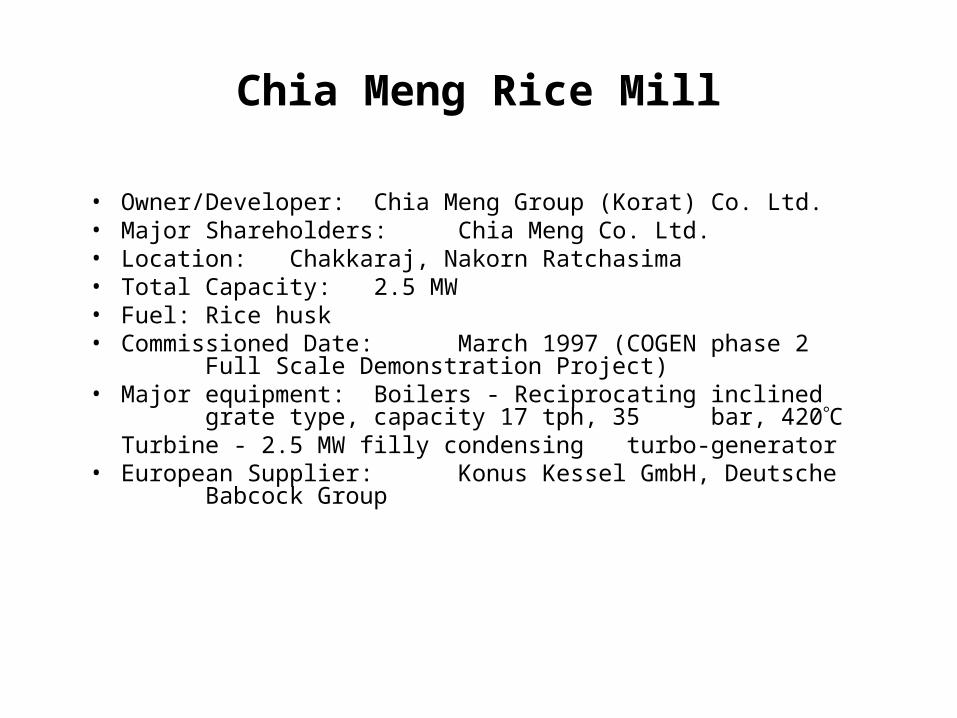
Chia Meng Rice Mill
• Owner/Developer: Chia Meng Group (Korat) Co. Ltd.• Major Shareholders: Chia Meng Co. Ltd.• Location: Chakkaraj, Nakorn Ratchasima• Total Capacity: 2.5 MW• Fuel: Rice husk• Commissioned Date: March 1997 (COGEN phase 2
Full Scale Demonstration Project)• Major equipment: Boilers - Reciprocating inclined
grate type, capacity 17 tph, 35 bar, 420CTurbine - 2.5 MW filly condensing turbo-generator
• European Supplier: Konus Kessel GmbH, Deutsche Babcock Group

Palm oil industry
• Energy situation– Old cogeneration plants (20 to 50 years) with low pressure
boilers and less efficient turbines– Not possible to sell electricity in the past– Seasonal operation using only fibre and shell
• Emerging trend– Need to replace old cogeneration system– Good potential for high pressure boilers and efficient turbines– Excess power exported to grid– Use of empty fruit bunches, fibre and shell– Plant operation throughout the year– Already few palm oil mills started implementing efficient
cogeneration systems

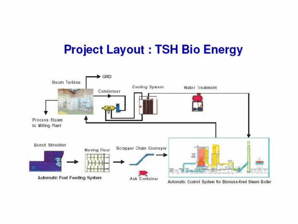
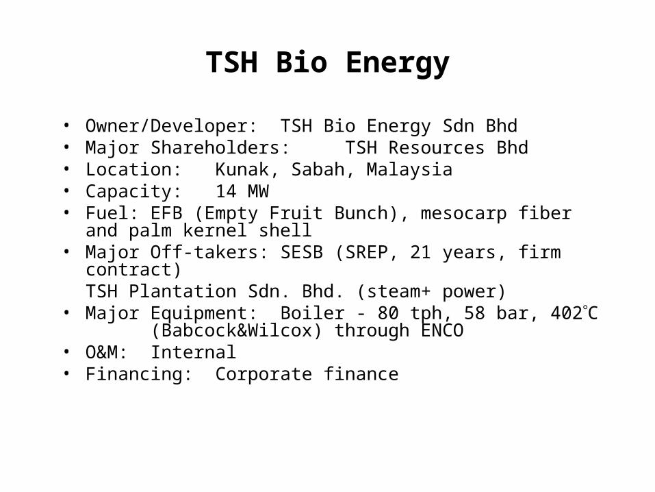
TSH Bio Energy
• Owner/Developer: TSH Bio Energy Sdn Bhd• Major Shareholders: TSH Resources Bhd• Location: Kunak, Sabah, Malaysia• Capacity: 14 MW• Fuel: EFB (Empty Fruit Bunch), mesocarp fiber
and palm kernel shell• Major Off-takers: SESB (SREP, 21 years, firm contract)
TSH Plantation Sdn. Bhd. (steam+ power)
• Major Equipment: Boiler - 80 tph, 58 bar, 402C (Babcock&Wilcox) through
ENCO• O&M: Internal• Financing: Corporate finance