Embed Size (px)
Citation preview
Corresponding author: Seung-Yop Lee E-mail: [email protected]
Journal of Bionic Engineering 13 (2016) 292–302
Bioinspired Segment Robot with Earthworm-like Plane Locomotion
Chang-Woo Song, Dong-Jun Lee, Seung-Yop Lee Department of Mechanical Engineering, Sogang University, 1 Shinsu-dong, Mapo-gu, Seoul 121-742, Republic of Korea
Abstract In this paper, a miniaturized segment robot using solenoids is developed to mimic the plane locomotion of earthworms. The
bioinspired robot is composed of five segmented bodies, and one segment has two solenoid actuators. This robot can move linearly and it can also turn due to the pair of solenoid actuators that facilitate the earthworm-like peristaltic locomotion. We have designed a miniaturized solenoid with a permanent magnet plunger in order to increase the total electromagnetic force. Atheoretical analysis is performed to predict the linear and turning motions of each segment, and the optimal profiles of input signals are obtained for fast locomotion. Experiments are then conducted to determine the linear and turning motions of the segment robot. It takes about 0.5 s for the five segments to complete one cycle of the peristaltic locomotion. In experiments, the segment robot is shown to have the linear and angular velocities of 27.2 mm·s−1 (0.13 body-length per second) and 2 degrees per second, respectively.
Keywords: bioinspired robot, earthworm, peristaltic locomotion, solenoid, segmented robot Copyright © 2016, Jilin University. Published by Elsevier Limited and Science Press. All rights reserved. doi: 10.1016/S1672-6529(16)60302-5
1 Introduction
Biologically inspired robots have been attracting a growing number of researchers for the last few decades, borrowing design concepts of structures, sensors and actuators from animals. Recently, there have been in-creasing researches on the segmented locomotion of earthworms, inchworms, caterpillars and snakes for the applications to medical endoscopes, rescue robots and industrial inspection systems[1–5]. In order to mimic the peristaltic or serpentine motions and soft bodies of segmented animals, various kinds of biomimetic robots have been presented such as discrete, serpentine and soft robots[1]. Recently, some researchers have devel-oped soft-bodied robots, which use soft or compliant materials and endure large strains when it is operated in normal state[5–7]. In order to meet the design constraints of the worm-like locomotion, various robots with flexible bodies or multi-segments have been stud-ied[8–17].
The soft or segmented robots to mimic the crawling mechanism of soft bodied creatures such as earthworms, inchworms and caterpillars can be classified according to the types of actuators, such as Shape Memory Alloy
(SMA)[7–10], piezoelectric materials[13], electroactive polymers[14–16] and electromagnetic actuators[17–19]. SMA has an advantage for the biomimetic micro robots in the aspects of simple structure, high energy density and large displacement, but low speed and slow response are its drawbacks. Various piezoelectric actuators for the earthworm-like locomotion show fast response and large output force. However, they require high voltage to implement satisfactory performance. Ionic Polymer Metal Composite (IPMC), which is one of electro-active polymers, produces large displacement, but small output forces limit its widespread use.
In general, electromagnetic actuators have many advantages such as fast response, simple control law and low manufacturing cost compared with the other actua-tors[19]. Crawling locomotion by electromagnetic ac-tuators mainly uses the impact-driven force or stick-slip motion. Ito et al. suggested an impact-driven robot with a Permanent Magnet (PM) surrounded by a coil[20]. Min et al. proposed a similar actuator system using two coils at the end of each side and PM is driven by electro-magnetic forces between the coils and PM[21]. Kim et al. introduced a new robotic mechanism using magnetic force and torque control in a rotating magnetic field for a

Song et al. Bioinspired Segment Robot with Earthworm-like Plane Locomotion 293
looping gait[22]. The authors have designed a multi-segmented robot
using four solenoids mimicking earthworm’s locomo-tion[19], where the biomimetic segmented robot enables bi-directional actuation and high-speed locomotion re-gardless of friction conditions. However, the earth-worm-like segmented robots with turning locomotion have not been implemented.
In this paper, a miniaturized robot with five-segmented bodies is developed to mimic the peri-staltic plane locomotion of earthworms, as the extension of the linear electromagnetic actuation in the previous work[19]. The segmented robot has a novel actuation for high-speed linear and turning motions using solenoids with permanent magnet plungers. Each segment of the segmented body is actuated by a pair of solenoids, and the linear and turning motions are easily generated by the in-phase and out-of-phase actuation of the solenoid pair. The theoretical analysis was performed to deter-mine the translational and rotational motions of each segment, and the experimental locomotion speeds are compared to the theoretical predictions.
2 Design of a segmented robot
2.1 Earthworm locomotion Soft-bodied organisms such as earthworms, ge-
ometrids, inchworms and caterpillars are moving based on the peristaltic or undulatory locomotion. Like all annelids, a typical earthworm Lumbricus terrestris has a segmented body. From front to back, the basic shape of the earthworm is a cylindrical tube, divided into a series of segments. Except for the mouth and anal segments, each segment carries bristle-like hairs called lateral setae used to anchor parts of the body during movement. As earthworms crawl forward, waves of circumferential and longitudinal muscle contractions pass posteriorly along their constant-volume body segments, forming back-ward peristaltic waves in the opposite direction to lo-comotion[23], as shown in Fig. 1.
When the longitudinal muscles of a segment con-tract, the segment becomes short and wide, and the setae extend so that the segment can anchor against the surface with high friction. When the circumferential muscles of a segment contract, the segment becomes long and thin and the setae retract so that the segment can advance over the surface. These waves of muscle contraction result in a pulsatile form of locomotion[23,24].
Undulatory locomotion(d)
Turning locomotion(c)
Linear locomotion(b)
friction
Movement
Contracted circumferential muscle Relaxed longitudinal muscle
Relaxed circumferential muscle Contracted longitudinal muscle
Peristaltic direction
(a)
Fig. 1 (a) The peristaltic crawling of an earthworm Lumbricus terrestris over one cycle. When the longitudinal muscles of a segment contract, the segment becomes short and wide. When the circumferential muscles of a segment contract, the segment be-comes long and thin, moving forward; (b) the linear motion of the segmented robot mimicking earthworms; (c) the biomimetic right-turning motion of the segmented robot; (d) the biomimetic undulating motion of the segmented robot.
The crawling stroke of an earthworm is the distance traveled during one cycle of peristalsis. The locomotion of an earthworm over one cycle can be divided into two stages: the protrusion stage when the segments are ad-vancing over the surface, and the stance stage when the segments are anchored against the surface. Lumbricus terrestris has approximately 145 segments which ad-vance and anchor at different times during the peristaltic motion, and it crawls approximately at 0.1 to 0.2 body-length per cycle[24]. 2.2 Segment robot locomotion
The objective of this research is to develop a seg-mented robot mimicking the earthworm-like locomotion using solenoids. Figs. 1b–1d show three types of loco-motion of the segmented robot mimicking various mo-tions of an earthworm. For the linear motion shown in Fig. 1b, a pair of solenoid actuators in each segment generate synchronized forces in the same direction in order to move together. For turning locomotion, both solenoid actuators in each segment move 180 degrees out of phase by using the unsynchronized forces shown
Journal of Bionic Engineering (2016) Vol.13 No.2 294
in Fig. 1c. Translation and rotation are easily imple-mented by regulating the input current applied to sole-noid actuators.
The multi-segmented robot enables both linear and turning motions using more than two segments. How-ever, at least five segments are required to generate the undulatory locomotion shown in Fig. 1d. When one segment is actuated to move, high frictional force by remaining segments is needed for the actuated segment to move forward without slipping. In this study, a five-segmented robot is designed to mimic the earth-worm-like plane motion using solenoid actuators. 2.3 Solenoid design
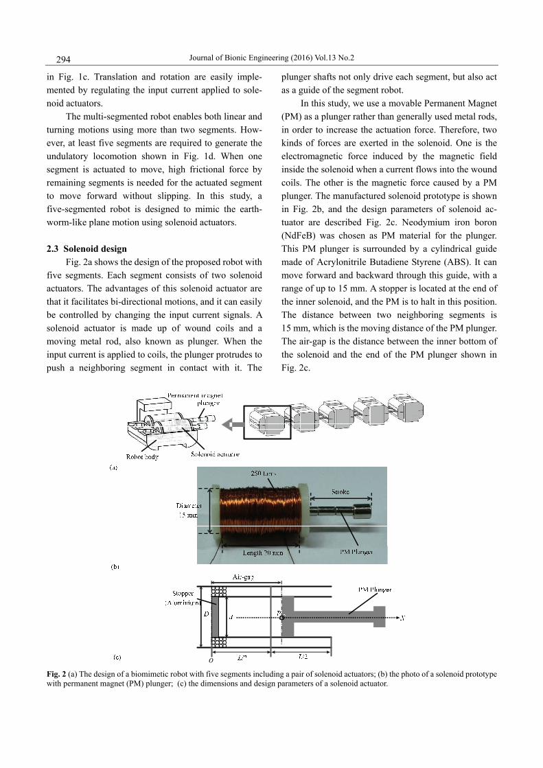
Fig. 2a shows the design of the proposed robot with five segments. Each segment consists of two solenoid actuators. The advantages of this solenoid actuator are that it facilitates bi-directional motions, and it can easily be controlled by changing the input current signals. A solenoid actuator is made up of wound coils and a moving metal rod, also known as plunger. When the input current is applied to coils, the plunger protrudes to push a neighboring segment in contact with it. The
plunger shafts not only drive each segment, but also act as a guide of the segment robot.
In this study, we use a movable Permanent Magnet (PM) as a plunger rather than generally used metal rods, in order to increase the actuation force. Therefore, two kinds of forces are exerted in the solenoid. One is the electromagnetic force induced by the magnetic field inside the solenoid when a current flows into the wound coils. The other is the magnetic force caused by a PM plunger. The manufactured solenoid prototype is shown in Fig. 2b, and the design parameters of solenoid ac-tuator are described Fig. 2c. Neodymium iron boron (NdFeB) was chosen as PM material for the plunger. This PM plunger is surrounded by a cylindrical guide made of Acrylonitrile Butadiene Styrene (ABS). It can move forward and backward through this guide, with a range of up to 15 mm. A stopper is located at the end of the inner solenoid, and the PM is to halt in this position. The distance between two neighboring segments is 15 mm, which is the moving distance of the PM plunger. The air-gap is the distance between the inner bottom of the solenoid and the end of the PM plunger shown in Fig. 2c.
Fig. 2 (a) The design of a biomimetic robot with five segments including a pair of solenoid actuators; (b) the photo of a solenoid prototype with permanent magnet (PM) plunger; (c) the dimensions and design parameters of a solenoid actuator.

Song et al. Bioinspired Segment Robot with Earthworm-like Plane Locomotion 295
The force acting on the PM plunger is proportional to the change in inductance of the coil with respect to the change in the position of the plunger as well as the cur-rent flowing through the coil. The design parameters affecting the electromagnetic performance of the sole-noid actuator are the length and diameter of the solenoid, the air gap, the number of coils and the input current. In order to design the solenoid actuator, some variables are fixed, such as the input current applied to the coil (±0.6 A), the air gap from the center of the solenoid (10 mm), the diameter of the coil (0.2 mm), and the magnetic field intensity of the PM (4000 Gauss). Design parameters that generate the electromagnetic force (0.6 N) are determined. The design parameters are the solenoid length (l=20 mm) and the number of coils (N=1250 turns), and the other diameter (D=15 mm) for the five segment robot[25].
3 Dynamic model of locomotion
The linearly moving mechanism of the proposed
segmented robot with five segments is shown in Fig. 3. The developed actuator requires five steps to complete a cycle of linear locomotion. In the first step, the pushing force is generated between the first and second segments by the pair of plungers in first segment when currents flow into the coils of the solenoids. The first segment moves forward when the pushing force Fp(x) of the first segment by the pair of plungers is larger than the friction force between the first segment and the ground. Since the friction forces of the other segments are larger than the reaction force of the pair of plungers in the first segment, the remaining segments do not move backward, as shown in Figs. 3a and 3b.
In the second step, the second segment moves forward with the retracting force Fr(x) of the first pair of plungers in the first segment and the pushing force Fp(x) of the second pair of plungers in the second segment (Figs. 3c and 3d). In the third and fourth steps, the third and fourth segments move forward as in the second step. In the last step, the other segments remain still while the
Fp Ffric Fr
x
x
x
Fp
Ffric
Fr
Ffric<Fr+Fp<4Ffric
(a)
(b)
(c)
(d)
(e)
xΔx x− Δ
Fig. 3 Schematic diagram of peristaltic locomotion of the five segmented robot using solenoids; (a) and (b) the motion of the first seg-ment; (c) and (d) the motion of the second segment; (e) the motion of the third segment and the relationship between electromagnetic (pushing and retraction) forces and friction one and the condition to move the segmented body.
Journal of Bionic Engineering (2016) Vol.13 No.2 296
fifth segment moves forward from the retracting force of the fourth pair of plungers. The electromagnetic pushing and retracting forces depend on the positions of the so-lenoid and the plunger. Therefore, the pushing (Fp) and retracting (Fr) forces are slightly different along the moving direction. However, since the experiments in section 4.2 ensure that the difference is negligible, it is assumed that the retracting and pushing forces are the same in this theoretical analysis. Therefore, these two pushing Fp(x) and retracting Fr(x) forces are used to operate the second, third, and fourth segments of the segmented robot, as shown in Fig. 3d.
Fact(x) = Fp(x)+ Fr(x)=4F(x), (1)
where F(x) is the actuation force by one solenoid ac-tuator. When the first and last segments are actuated by only pushing or retracting forces, the total actuating force generated by the pair of solenoids becomes Fact(x)=2F(x).
The electromagnetic forces (pushing and retracting forces) generated by the solenoid actuators in each segment and the friction force that occurs between the ground and each segment affects the locomotion of the segmented robot. The dynamic equation of the seg-mented robot’s locomotion is a function of the total electromagnetic force and friction force. The governing equation of linear locomotion of the segmented robot is shown by
( )act fricmx F x F ,= − (2)
where, m and x indicate the mass and acceleration of each segment. The friction force arises between each segmented body and the ground. When this segmented robot operates in linear locomotion, the friction force is assumed to be constant. The friction force between the PM plunger and the inner surface of the solenoid ac-tuator is assumed to be approximately zero. The friction force between the segment and the ground depends on the velocity, the angle of the plane, and the roughness of the ground (Ffric=μkmg). Here, the kinetic friction coef-ficient is μk= 0.35. Moreover, the total electromagnetic force generated by the solenoid actuator should satisfy Ffric<Fact(x)<4Ffric to operate only one segment while not moving the remaining four segments. The relationship between the pushing and retracting forces generated by the solenoid actuator and the friction force is shown in Fig. 3e until the movement of the third segment. The
third segment moves forward when the electromagnetic force is larger than the friction force caused by third segment.
In order to calculate the linear locomotive speed of the segmented robot, the velocity of each segment is needed. The total electromagnetic force is applied to the solenoid actuator in the nth segment. Next, applying the energy conservation law, Eq. (3) is obtained instead of having to solve the nonlinear Eq. (2). The current step velocity vn,c of the nth segment is obtained by a constant input current before the collision:
2 2, ,
1 1( ( ) )d2 2
n
n
x xn p act fric n cx
mv F x F x mv ,+Δ
+ − =∫ (3)
where vn,p indicates the velocity of the previous step. The velocity and the electromagnetic force are based on the solenoid position and the input current applied to the wound coils. The equation can be simplified for the numerical analysis in order to calculate the current ve-locity using the averaged force actF applied between the two neighboring segments:
2 2 2 ( )n,c n,p act fricv v F F x.m
= + − Δ (4)
Two nearby segments abruptly crash when the rear segment reaches the location of the front one. When a collision between the two neighboring segments occurs at the end of each locomotive step, it is assumed to be inelastic with the restitution coefficient of zero, in order to eliminate the backward or rebound motion. The maximum stroke between two neighboring segments is 15 mm as shown in Fig. 4a. The angular displacement caused by unsynchronized motion of the solenoid pair can be calculated by the moving distance of PM plunger and the distance between the two plungers of the first segment. As shown in Fig. 4b, the angular displacement becomes
1 sin tantan M MR
tot
( L g ) ,L
θ θθ − +
= (5)
where, L is the length of one segment and Ltot indicates the total length of the segmented robot. θM=tan−1(x/y) represents the angular displacement of the first segment. x is the moving distance of the PM plunger inside the solenoid and y is the distance between the PM plunger and the far side of the segment. When one segment has the length of L = 37 mm and the width of W = 41 mm, the angular displacement θR=1.57˚ with θM = 8.82˚.

Song et al. Bioinspired Segment Robot with Earthworm-like Plane Locomotion 297
W=
41 m
m
L = 37 mm
Fig. 4 Linear and angular displacement of the segmented robot; (a) maximum stroke between two segments is 15 mm; (b) angular dis-placement by asymmetric motion of the pair of solenoid. 4 Experiments
4.1 Experimental apparatus As shown in Fig. 5a, we construct an experimental
setup to measure the force generated by the solenoid actuator using a load cell (CASTM PW4MC3). The resistance of the coils is measured with a multimeter. In order to measure the displacement of the first segment, we use an infrared sensor (SHARP 2Y0A02) as shown in Fig. 5b. This infrared sensor system has a distance measuring range of 20 cm to 150 cm, with a tolerance of approximately 0.3 mm.
In section 2.3, we have determined the design pa-rameters of the solenoid actuator: the number of coils (1250 turns) and the solenoid length (20 mm). The re-sistance of the solenoid is about 20 ohms. The distance between two neighboring segments is 15 mm, which is the moving distance over one step. The air-gap is the distance between the inner bottom of the solenoid and the end of the PM plunger as shown in Fig. 2c. When the air-gap varies from 5 mm to 15 mm for the constant input current (0.6 A), the experimental pulling and pushing magnetic forces induced by one solenoid are plotted in Fig. 6. In the graph, the total magnetic forces are measured by the load cell as a function of the air-gap. Since the difference between the pulling and pushing magnetic forces is relatively small, the same curve fit-ting is used to approximate both magnetic forces. The
Infrared sensor
Base
Power supply
(b) Fig. 5 Experimental apparatus. (a) Measurement of the output force by the solenoid actuator; (b) the displacement measurement of the segmented robot using an infrared sensor. solid line indicates the polynomial curve-fitting to the experimental data and the curve-fitting equation be-comes
F(x)= –0.003545x2+0.07347x+0.2231. (6)
The curve-fitting equation is used for the calculation of theoretical velocity of each segment in Eq. (4). The prototype of the proposed segmented robot is shown in Fig. 7a. The manufactured body consists of five seg-

Journal of Bionic Engineering (2016) Vol.13 No.2 298
ments and each segment has two solenoid actuators. The size and mass of each segment are 37 mm × 41 mm × 31 mm (length × width × height) and 50 g, respectively. The total length of the segment robot is 210 mm when all the segments are connect to one another and the end of the PM plunger is attached to the stopper. However, the total length reaches 270 mm when all the PM plungers protrude from the solenoid actuators. Each segment moves forward or backward by approximately 15 mm over one cycle. 4.2 Experiment of linear locomotion
In experiments, the linear and turning motions of the five segmented robot are observed using a high speed camera capturing 600 frames per second. In order to generate the linear motion, the current signals of ±0.6 A are applied to actuate the pair of PM plungers at the same
Pulling forcePushing forceCurve fitting
Forc
e (N
)
5 6 7 8 9 10 11 12 13 14 150.45
0.5
0.55
0.6
0.65
Air-gap (mm) Fig. 6 The experimental pulling and pushing magnetic forces by one solenoid actuator and the polynomial curve-fitting graph.
(b)
(d)
(a)
(e)
(c)
(a)
1 cm3
Fig. 7 Captured images of the linear motion of the segmented robot over one cycle using a high-speed camera; (a) t = 0 s; (b) t = 0.1 s; (c) t = 0.2 s; (d) t = 0.3 s; (e) t = 0.4 s.
time. Then the displacement of the first segment is measured using an infrared sensor, as shown in Fig. 5b. The captured image at each step over one cycle are shown in Figs. 7b to 7e. It takes about 0.1 seconds to move one segment, and thus it takes approximately 0.5 second to complete the linear locomotion over one cycle. In order to maximize the speed of locomotion, time intervals are controlled to obtain the optimal pro-files of the input current signals in each segment. Fig. 8a shows the time profiles of the input currents applied to the left and right solenoid actuators over 1 cycle (0.5 s) of each segment for the linear motion.
All the solenoid actuators of the five segmented robot are controlled by a microprocessor (Atmega 2560/Arduino mega) in order to drive each segment sequentially. Especially, time intervals, switching tim-ing and input voltages are precisely regulated to opti-mize the locomotion of the segmented robot for both the linear and turning motions. Time intervals and input voltages are controlled using the Arduino device and program.
The theoretical displacement calculated by Eqs. (1) and (4) and the actual one by experiments are compared in Fig. 9a. The solid and dashed lines shown in Fig. 9a represent the theoretical and experimental displacements of the linear motion. The theoretical velocity of the segmented robot is 15.05 mm per cycle (30.1 mm·s−1). However, the average experimental velocity is about 27.2 mm·s−1 over two cycles. The experimental velocity is smaller than the theoretical one. When a collision between two segments occurs at each step of locomotion, it is assumed to be totally inelastic with the restitution coefficient of zero in the theoretical analysis. However, the backward or rebound motion occurs in experiments, causing the fluctuation in displacement after the first step of each cycle.
Fig. 9b shows the experimental displacements of the first segment over 4 cycles. The experiments are conducted three times. The displacement outlines are similar in the three experimental results in the early cycles. However, the discrepancy in the experiments increases according to changes of time, because fric-tional and environmental conditions are a little different in each experiment. 4.3 Experiment of turning locomotion
The segmented robot is capable of not only linear

Song et al. Bioinspired Segment Robot with Earthworm-like Plane Locomotion 299
Right solenoid
Inpu
t sig
nal (
A)
0 50 100 150 200 250 300 350 400 450 500−1
0
1
−1
0
1
−1
0
1
−1
0
1
1 st solenoid
(b)
2 nd solenoid
3 rd solenoid
4 th solenoid
0 50 100 150 200 250 300 350 400 450 500
0 50 100 150 200 250 300 350 400 450 500
0 50 100 150 200 250 300 350 400 450 500Time (ms)
500
500
Left solenoidIn
put s
igna
l (A
)
0 50 100 150 200 250 300 350 400 450−1
0
1
−1
0
1
−1
0
1
−1
0
1
1 st solenoid
(a)
2 nd solenoid
3 rd solenoid
4 th solenoid
0 50 100 150 200 250 300 350 400 450 500
0 50 100 150 200 250 300 350 400 450
0 50 100 150 200 250 300 350 400 450 500Time (ms)
Fig. 8 Profiles of input currents applied to each solenoid actuator for the segmented robot; (a) linear locomotion over 1 cycle (0.5 s); (b) right-turning motion over 1 cycle (0.5 s).
0 0.2 0.4 0.6 0.8 1.0 1.2 1.4 1.60
5
10
15
20
25
30
35
Dis
plac
emen
t (m
m)
40
45
50
55
(b)Time (s)
o
Experiment 1
Experiment 3
Experiment 2
0 0.1 0.2 0.3 0.4 0.5 0.6 0.7 0.8 0.9 1.00
5
10
15
20
25
30
35
Dis
plac
emen
t (m
m)
o
Theory
Experiment
(a)Time (s)
Fig. 9 The linear motion of the first segment of the biomimetic segmented robot; (a) the comparison of theoretical and experimental displacements; (b) experimental displacements over 4 cycles. locomotion, but also turning locomotion by bending the five segments sequentially. Fig. 8b shows the time pro-files of the input currents applied to the left and right solenoid actuators of five segments over 1 cycle (0.5 s) for the right-turning motion. Opposite input signals (±0.6 A) are applied to the pair of solenoid actuators, corresponding to the solid and dashed lines in Fig. 8b. Then the solenoid pair moves 180 degrees out of phase to bend the segmented robot.
Fig. 10a shows the captured images of the right-turning motion of the segmented robot over one
cycle. It takes about 0.1 seconds to move one segment and it takes 0.5 seconds to complete the turning loco-motion over one cycle, similar to the process of linear locomotion. The captured images of right turning mo-tion up to 90 degrees are shown in Figs. 10b–10f. These figures show the turning locomotion of the segmented robot after 10 cycles (t = 5 s), 30 cycles (t = 15 s), 50 cycles (t = 25 s), 70 cycles (t = 35 s), and 90 cycles (t = 45 s). The right angled turn is almost complete after about 90 cycles as shown in Fig. 10f. It is noted that the linear and turning locomotion of the segmented robot

Journal of Bionic Engineering (2016) Vol.13 No.2 300
(a) (a) (c)
(d) (e) (f)
(b)
Fig. 10 Captured images of the right-turn motion of the segmented robot using a high-speed camera; (a) sequential images of the right-turn motion over 1 cycle (t = 0.5 s); (b) locomotion after 10 cycles, (c) locomotion after 30 cycles; (d) locomotion after 50 cycles; (e) loco-motion after 70 cycles; (f) locomotion after 90 cycles (t = 45 s).
Time (s)(a)0 5 10 15 20 25 30 35 40 45
0
10
20
30
40
50
60
70
80
90
o
Theory
Experiment
Time (s)0 5 10 15 20 25 30 35 40 45
0
10
20
30
40
50
60
70
80
90
o
Experiment 1
Experiment 3
Experiment 2
(b)
Fig. 11 The right-turning motion of the biomimetic segmented robot; (a) the comparison of theoretical and experimental angular motions; (b) three experimental results of angular motion over 90 cycles (45 s). can easily be operated by controlling the pair of sole-noids in each segment.
Theoretical angular movements calculated by Eq. (5) are compared to the experimental results shown in Fig. 11a. The solid and dashed lines shown in Fig. 11a indicate the theoretical and experimental angular dis-placements of the segmented robot over 90 cycles (45 s). In the theoretical analysis, the angular velocity is about 1.6 degrees per cycle (3.2 degrees per second) and it takes approximately 28 seconds to rotate itself up to 90 degrees. Fig. 11b shows the experimental angular
movements repeated three times. In the experimental results, the average angular velocity over 90 cycles is about 1 degrees per cycle (2 degrees per second). This number is smaller than the theoretical one due to the coupled motion between the adjacent segments and the unwanted backward motion in the experiments.
5 Conclusion
In this study, a biomimetic robot with multi-seg-mented bodies mimicking the peristaltic plane locomo-tion of earthworms was developed. The robot consists of
Song et al. Bioinspired Segment Robot with Earthworm-like Plane Locomotion 301
five segmented body and each segment is actuated by a pair of solenoids with permanent magnet plungers. The biomimetic segmented robot can cause the change of direction by making each solenoid pair 180 degrees out of phase to bend the earthworm-like body, as well as the linear motion by peristaltic locomotion. The total mag-netic force induced by one solenoid are measured by the load cell as a function of the air-gap, and the curved-fitting magnetic force is used to calculate the dynamic equations of the linear and turning motions driven by each segment. The theoretical linear and an-gular speeds are 30.1 mm·s−1 and 3.2 degree per second respectively. The theoretical analysis is also performed to obtain the optimal profiles of input signals for fast translation and rotation. On the other hands, the ex-periments using the five-segmented robot show that it takes 0.5 s to complete the locomotion over one cycle and the linear speed becomes 27.2 mm·s−1 (0.13 body-length per second). Also, the segmented robot completes the turning motion for the change of direction after 90 cycles is about 1 degree per cycle (2 degree per second).
The novel mechanism to generate both linear and turning motions by the simple and low-cost solenoid pair could be applied to mimic the peristaltic and serpentine motions of various flexible or segmented insects. If the solenoid pair is connected to other pair in crisscross pattern, the 2-dimensional actuation of the solenoid pair would be also extended to the 3-dimentional motion of the segmented mechanism for the application to rescue robots and medical endoscopes.
Acknowledgment
This research was supported by 2013R1A2A2A01068159 and 2015M2B2A9031556 through the National Research Foundation of Korea funded by Ministry of Science ICT & Future Planning.
References
[1] Trivedi D, Rahn C, Kier W, Walker D. Soft robotics: Bio-logical inspiration, state of the art and future research. Ap-plied Bionics and Biomechanics, 2008, 5, 99–117.
[2] Hirose S. Biologically Inspired Robots: Snake-Like Loco-motors and Manipulators. Oxford University Press, New York, USA, 1993.
[3] Cho K J, Koh J S, Kim S, Chu W S, Hong Y, Ahn S H. Review of manufacturing processes for soft biomimetic
robots. International Journal of Precision Engineering and Manufacturing, 2009, 10, 171–181.
[4] Hosokawa D, Ishikawa T, Morikawa H, Imai Y, Yamaguchi T. Development of a biologically inspired locomotion sys-tem for a capsule endoscope. International Journal of Medical Robotics and Computer Assisted Surgery, 2009, 5, 471–478.
[5] Trimmer B A. New challenges in biorobotics: Incorporating soft tissue into control systems. Applied Bionics and Bio-mechanics, 2008, 5, 119–126.
[6] Seok S, Onal C D, Cho K, Wood R J, Rus D, Kim S. Meshworm: A peristaltic soft robot with antagonistic nickel titanium coil actuators. IEEE/ASME Transactions on Mechatronics, 2013, 18, 1485–1498.
[7] Lin H T, Leisk G G, Trimmer B. GoQBot: A caterpil-lar-inspired soft-bodied rolling robot. Bioinspiration & Biomimetics, 2011, 6, 026007.
[8] Koh J, Cho K. Omega-shaped inchworm-inspired crawling robot with large-index-and-pitch (LIP) SMA spring actua-tors. IEEE/ASME Transactions on Mechatronics, 2013, 18, 419–429.
[9] Yuk H, Kim D, Lee H, Jo S, Shin J H. Shape memory al-loy-based small crawling robots inspired by C. elegans. Bioinspiration & Biomimetics., 2011, 6, 046002.
[10] Menciassi A, Gorini S, Pernorio G, Dario P. A SMA actuated artificial earthworm. Proceedings of the IEEE International Conference on Robotics & Automation, New Orleans, LA, USA, 2004, 3282–3287.
[11] Li G Y, Zhang H X, Zhang J W, Hildre H P. An approach for adaptive limbless locomotion using a CPG-based reflex mechanism. Journal of Bionic Engineering, 2014, 11, 389–399.
[12] Li G Y, Li W, Zhang J W, Zhang H X. Analysis and design of asymmetric oscillation for caterpillar-like locomotion. Journal of Bionic Engineering, 2015, 12, 190–203.
[13] Lobontiu N, Goldfarb M, Garcia E. A piezoelectric-driven inchworm locomotion device. Mechanism and Machine Theory, 2001, 36, 425–443.
[14] Guo S, Shi L, Xiao N, Asaka K. A biomimetic underwater microrobot with multifunctional locomotion. Robotics and Autonomous Systems, 2012, 60, 1472–1483.
[15] Firouzeh A, Ozmaeian M, Alasty A, Irajizad A. An IPMC-made deformable-ring-like robot. Smart Materials and Structures, 2012, 21, 065011.
[16] Arena P, Bonomo C, Fortuna L, Graziani S. Design and control of an IPMC wormlike robot. IEEE Transaction on Systems, Man, and Cybernetics, 2006, 36, 1044–1052.
[17] Lu H, Zhu J, Guo Y. An inchworm mobile robot using elec-
Journal of Bionic Engineering (2016) Vol.13 No.2 302
tromagnetic linear actuator. IEEE/ASME Transactions on Mechatronics, 2009, 19, 1116–1126.
[18] Lee K M, Kim Y S, Paik J K, Shin B H. Clawed miniature inchworm robot driven by electromagnetic oscillatory ac-tuator. Journal of Bionic Engineering, 2015, 12, 519–526.
[19] Shin B H, Choi S W, Bang Y B, Lee S Y. An earthworm-like actuator using segmented solenoids. Smart Materials and Structures, 2011, 20, 105020.
[20] Ito T, Ogushi T, Hayashi T. Impulse-driven capsule by coil-induced magnetic field implementation. Mechanism and Machine Theory, 2010, 45, 1642–1650.
[21] Min H, Lim H, Kim S. A new impact actuator using linear momentum exchange of inertia mass. Journal of Medical
Engineering & Technology, 2006, 26, 265–269. [22] Kim S H, Hasi S, Ishiyama K. Hybrid magnetic mechanism
for active locomotion based on inchworm motion. Smart Materials and Structures, 2013, 22, 027001.
[23] Trueman E R. Locomotion in Soft-Bodied Animals. Edward Arnold, London, UK, 1975.
[24] Quillin K M. Kinematic scaling of locomotion by hydro-static animals: Ontogeny of peristaltic crawling by the earthworm lumbricus terrestris. Journal of Experimental Biology, 1999, 202, 661–674.
[25] Song C W, Lee S Y. Design of a solenoid actuator with a magnetic plunger for miniaturized segment robots. Applied Sciences, 2015, 5, 595–607.